ImagingofCosmeticFacialImplantsandGrafts - AJNR · ImagingofCosmeticFacialImplantsandGrafts ......
8
REVIEW ARTICLE Imaging of Cosmetic Facial Implants and Grafts C.J. Schatz and D.T. Ginat ABSTRACT SUMMARY: A wide variety of implants and grafts have been used for cosmetic facial surgery, including forehead, nose, cheek, lip, and chin augmentation. Some of the implant materials include silicone, expanded polytetrafluoroethylene (Gore-Tex), hydroxylapatite, and porous polyethylene (Medpor). Grafts include bone and cartilage, which can be prepared as “Turkish Delight” for rhinoplasty. Imaged facial implants and grafts can be encountered incidentally or purposely to evaluate complications. Many of these materials have distinct radiologic imaging features and should not be misinterpreted as pathology. Conversely, implant complications should be appropriately recognized by using a focused imaging approach. The purpose of this article was to review the different types of cosmetic facial implants and grafts with an emphasis on their expected and complicated radiologic imaging appearances. A ccording to the American Society of Plastic Surgeons, a total of 243,777 rhinoplasty surgeries, 46,931 forehead lift surger- ies, 20,680 chin augmentation surgeries, and 11,996 cheek im- plant surgeries were performed in the United States in 2011. 1 On occasion, patients who have undergone facial augmentation pro- cedures present for radiologic imaging. Therefore, it is important to be familiar with the common types of cosmetic facial implants and their complications. The imaging features of these implants differ on the basis of location and composition. Often, implants are used at the same time in different locations to achieve bal- anced proportions of facial tissues. The imaging features of com- monly used material for cosmetic facial implants are reviewed in the following sections and in the Table. 2-5 It is important to rec- ognize the expected imaging appearances of implants and their complications to avoid misdiagnosing these as neoplastic pro- cesses, for instance. 6,7 AUGMENTATION TECHNIQUES Forehead Cosmetic forehead augmentation (browplasty) can be performed for the treatment of frown lines and to mitigate bony deficiencies. 8,9 Popular materials used in the midforehead include soft expanded polytetrafluoroethylene strips and silicone implants. 7 The expanded polytetrafluoroethylene strips (Gore-Tex; W.L. Gore & Associates, Newark, Delaware) are usually 1- to 2-mm thick and positioned in a vertical orientation (Fig 1). On the other hand, shield-shaped silicone implants can cover a relatively larger area, and irregular edges and perforations limit implant motion and capsular contraction. 8 Cheek Cheek augmentation (malarplasty) consists of adding volume to either the malar or submalar space or a combination of these to compensate for osseous and soft-tissue deficiencies and to elevate the cheek subcutaneous tissues. 10-12 Specifically, submalar im- plants are positioned over the anterior walls of the maxilla (Fig 2). On the other hand, malar implants are positioned over the malar eminences and zygomatic bones in a more superior and lateral position (Fig 3). Combined malar-submalar implants span both the malar eminence and the submalar triangle. The implants are typically inserted into the subperiosteal pocket via a transoral approach through the canine fossa. 10 In the past, ovoid “button” implants were used for cheek augmentation. Currently, Silastic (Dow Corning, Auburn, Michigan) shell im- plants are especially popular and have characteristic crescent shapes to match the contours of the underlying anatomy. The implants are available in a variety of sizes and can be further cus- tomized intraoperatively. Small holes are sometimes incorpo- rated into the implant to promote tissue ingrowth. In addition, the implants can be secured with sutures or screws. Other mate- rials that have been used for midface augmentation include po- rous polytetrafluoroethylene (Medpor; Stryker, Allendale, New Jersey) and expanded polytetrafluoroethylene (Gore-Tex). 10,12 From Beverly Tower Wilshire Advanced Imaging (C.J.S.), Beverly Hills California; University of Southern California Keck School of Medicine (C.J.S.), Los Angeles, California; and Department of Radiology (D.T.G.), Massachusetts General Hospital and Harvard Medical School, Boston, Massachusetts. Please address correspondence to Daniel T. Ginat, MD, MS, 55 Fruit St, Boston, MA 02114; e-mail: [email protected] Indicates open access to non-subscribers at www.ajnr.org http://dx.doi.org/10.3174/ajnr.A3214 1674 Schatz Sep 2013 www.ajnr.org
Transcript of ImagingofCosmeticFacialImplantsandGrafts - AJNR · ImagingofCosmeticFacialImplantsandGrafts ......

REVIEWARTICLE
Imaging of Cosmetic Facial Implants and GraftsC.J. Schatz and D.T. Ginat
ABSTRACT
SUMMARY: Awide variety of implants and grafts have been used for cosmetic facial surgery, including forehead, nose, cheek, lip, and chinaugmentation. Some of the implantmaterials include silicone, expanded polytetrafluoroethylene (Gore-Tex), hydroxylapatite, and porouspolyethylene (Medpor). Grafts include bone and cartilage, which can be prepared as “Turkish Delight” for rhinoplasty. Imaged facialimplants and grafts can be encountered incidentally or purposely to evaluate complications. Many of these materials have distinctradiologic imaging features and should not be misinterpreted as pathology. Conversely, implant complications should be appropriatelyrecognized by using a focused imaging approach. The purpose of this article was to review the different types of cosmetic facial implantsand grafts with an emphasis on their expected and complicated radiologic imaging appearances.
According to the American Society of Plastic Surgeons, a total
of 243,777 rhinoplasty surgeries, 46,931 forehead lift surger-
ies, 20,680 chin augmentation surgeries, and 11,996 cheek im-
plant surgeries were performed in the United States in 2011.1 On
occasion, patients who have undergone facial augmentation pro-
cedures present for radiologic imaging. Therefore, it is important
to be familiar with the common types of cosmetic facial implants
and their complications. The imaging features of these implants
differ on the basis of location and composition. Often, implants
are used at the same time in different locations to achieve bal-
anced proportions of facial tissues. The imaging features of com-
monly used material for cosmetic facial implants are reviewed in
the following sections and in the Table.2-5 It is important to rec-
ognize the expected imaging appearances of implants and their
complications to avoid misdiagnosing these as neoplastic pro-
cesses, for instance.6,7
AUGMENTATION TECHNIQUESForeheadCosmetic forehead augmentation (browplasty) can be performed
for the treatment of frown lines and to mitigate bony deficiencies.8,9
Popular materials used in the midforehead include soft expanded
polytetrafluoroethylene strips and silicone implants.7 The expanded
polytetrafluoroethylene strips (Gore-Tex; W.L. Gore & Associates,
Newark, Delaware) are usually 1- to 2-mm thick and positioned in a
vertical orientation (Fig 1). On the other hand, shield-shaped silicone
implants can cover a relatively larger area, and irregular edges and
perforations limit implant motion and capsular contraction.8
CheekCheek augmentation (malarplasty) consists of adding volume to
either the malar or submalar space or a combination of these to
compensate for osseous and soft-tissue deficiencies and to elevate
the cheek subcutaneous tissues.10-12 Specifically, submalar im-
plants are positioned over the anterior walls of the maxilla (Fig 2).
On the other hand, malar implants are positioned over the malar
eminences and zygomatic bones in a more superior and lateral
position (Fig 3). Combined malar-submalar implants span both
the malar eminence and the submalar triangle.
The implants are typically inserted into the subperiosteal
pocket via a transoral approach through the canine fossa.10 In the
past, ovoid “button” implants were used for cheek augmentation.
Currently, Silastic (Dow Corning, Auburn, Michigan) shell im-
plants are especially popular and have characteristic crescent
shapes to match the contours of the underlying anatomy. The
implants are available in a variety of sizes and can be further cus-
tomized intraoperatively. Small holes are sometimes incorpo-
rated into the implant to promote tissue ingrowth. In addition,
the implants can be secured with sutures or screws. Other mate-
rials that have been used for midface augmentation include po-
rous polytetrafluoroethylene (Medpor; Stryker, Allendale, New
Jersey) and expanded polytetrafluoroethylene (Gore-Tex).10,12
From Beverly Tower Wilshire Advanced Imaging (C.J.S.), Beverly Hills California;University of Southern California Keck School of Medicine (C.J.S.), Los Angeles,California; and Department of Radiology (D.T.G.), Massachusetts General Hospitaland Harvard Medical School, Boston, Massachusetts.
Please address correspondence to Daniel T. Ginat, MD, MS, 55 Fruit St, Boston, MA02114; e-mail: [email protected]
Indicates open access to non-subscribers at www.ajnr.org
http://dx.doi.org/10.3174/ajnr.A3214
1674 Schatz Sep 2013 www.ajnr.org

NasalCosmetic rhinoplasty consists of altering the shape of the nose to
achieve a more attractive form and relationship with the sur-
rounding facial structures, while attempting to preserve the nor-
mal functions of the nose. Augmentation rhinoplasty consists of
FIG 1. Forehead implants. Axial (A) and coronal (B) CT images show thin strips of expanded polytetrafluoroethylene in the midline of theforehead in the region of the glabella.
Facial implant materialsMaterial Properties and Uses Imaging Appearance
Silicone rubber (Silastic) Rubber elastomer, well-tolerated and easilycustomizable, soft pliable consistency;indications: chin, lateral jaw, cheek, and noseaugmentation
CT: variable attenuation, usually denser thansoft tissue, but less dense than bone and bestdiscerned using bone windows;MRI: very low signal intensity on T1- and T2-weighted sequences
Expanded polytetrafluoroethylene(Gore-Tex)
Biocompatible, long-lasting but can beremoved surgically; indications: lower facelift, nasal and forehead augmentation
CT: higher attenuation relative to soft tissues,but less dense than bone;MRI: hypointense to fat on T1- and T2-weightedsequences
Polytetrafluoroethylene (Teflon) Obsolete Imaging features similar to those of Gore-TexPorous polyethylene (Medpor) Inert and biocompatible, low complication rate,
permanent; indications: lower face and nasalaugmentation; also used for orbital andauricular reconstruction; fibrovascularingrowth can render removal difficult
CT: attenuation between fat and water;MRI: hypointense to fat on T1- and T2-weightedsequences; enhancement may occur due tofibrovascular ingrowth
Hydroxylapatite Inert and biocompatible; blocks ofhydroxylapatite can allow fibrovascularingrowth and bony incorporation
CT: hyperdense, hyperattenuation similar tothat of bone; the implant can becomeincorporated into and inseparable from theadjacent bone;MRI: low signal on T1 and T2; enhancement mayoccur due to fibrovascular ingrowth
Bone Occasionally used for rhinoplasty, cheek, andchin augmentation; harvest sites include iliaccrest, cranium, turbinates, rib
CT: same as normal bone elsewhere; cortex andtrabecular can be identified unless resorptionhas occurredMRI: high T1 and T2 marrow signal and low-signalcortex are often discernible; in the earlypostoperative period, marrow edema withinthe graft may appear as low T1 and high T2signal
Cartilage Often used in rhinoplasty and sometimes chinaugmentation; harvest sites include nasalseptum, conchal cartilage, and costalcartilage; can be part of osteochondral grafts;can be diced and wrapped in Surgicel (TurkishDelight)
CT: soft-tissue density; may form a rim ofcalcification or ossification;MRI: usually low T2 and high T2 signal
AJNR Am J Neuroradiol 34:1674–81 Sep 2013 www.ajnr.org 1675
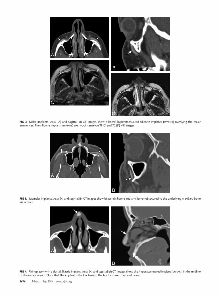
FIG 2. Malar implants. Axial (A) and sagittal (B) CT images show bilateral hyperattenuated silicone implants (arrows) overlying the malareminences. The silicone implants (arrows) are hypointense on T1 (C) and T2 (D) MR images.
FIG 3. Submalar implants. Axial (A) and sagittal (B) CT images show bilateral silicone implants (arrows) secured to the underlying maxillary bonevia screws.
FIG 4. Rhinoplasty with a dorsal Silastic implant. Axial (A) and sagittal (B) CT images show the hyperattenuated implant (arrows) in the midlineof the nasal dorsum. Note that the implant is thicker toward the tip than over the nasal bones.
1676 Schatz Sep 2013 www.ajnr.org

adding material to the nose and can be performed by using au-
tograft, such as bone (Fig 4), or alloplastic implants, such as sili-
cone rubber (Fig 5).13,14 Satisfactory results have also been ob-
tained with cartilage grafts, Medpor, Gore-Tex, and Mersilene
(Ethicon, Cincinnati, Ohio) mesh.1-18 “Turkish Delight” is a
unique augmentation preparation used for rhinoplasty composed
of diced cartilage mixed with a small amount of the patient’s
blood and wrapped in Surgicel (Ethicon).19 Variations of Turkish
Delight, consisting of diced polyethylene, have also been used.17
Different portions of the nose can undergo augmentation, includ-
ing the nasal dorsum, tip, columella, and combinations of these.
Premaxillary augmentation can be performed as an adjunct to
rhinoplasty to treat an excessively deep infranasal sulcus (premax-
illary underprojection) and an acute nasolabial angle.20,21 This
can be accomplished by using osteochondral grafts or a strip of
alloplastic material, such as silicone, positioned in the midline just
inferior to the anterior nasal spine of the maxilla (Fig 6). Some
silicone implants have a bat-wing configuration.20
LipSurgical augmentation of the lips (cheiloplasty) can be performed
to mitigate the changes that occur with aging, such as the devel-
opment of perioral rhythides and diminished fullness and ante-
FIG 6. Premaxillary implant. Axial CT image shows a hyperattenuatedsilicone implant positioned anterior to the midline of the maxilla(arrow).
FIG 7. Lip implant. Axial CT image shows a hyperattenuated, thin,curved expanded polytetrafluoroethylene lower lip implant (arrow).Also note the presence of hyperattenuated fillers in the region of theoral commissures.
FIG 5. Rhinoplasty with a dorsal bone graft. Axial (A) and sagittal (B) CT images show a linear bone graft positioned along the dorsum of the nose(arrows). Axial T2 (C) and sagittal postcontrast T1 (D) MR images show hyperintense fatty marrow within the bone graft (arrows).
AJNR Am J Neuroradiol 34:1674–81 Sep 2013 www.ajnr.org 1677

rior projection.22 Lip augmentation can also be performed in re-
sponse to fashion trends, in which full lips are deemed a desirable
trait.22 A variety of implants are available for lip augmentation,
including fat grafts, musculoaponeurotic system grafts, acellular
human dermis, and expanded polytetrafluoroethylene.22-25
These can be inserted via incisions made medial to the oral com-
missures and by threading the implant deep to the submucosal
plane.22 The implants are often given a trapezoidal shape, so that
these are thinner laterally to conform to the natural tapering of the
lips toward the oral commissures. Gore-Tex lip implants typically
measure �3 mm in thickness so that these are not excessively
stiff.24
ChinCosmetic chin augmentation (mentoplasty) can be performed to
treat a deficient chin projection, which results from soft-tissue
atrophy and retrusion of the mandible.26,27 Ideally the chin
should extend to the level of the vermillion border of the lower lip
FIG 8. Chin augmentationwith cartilage graft. Axial CT image shows achunk of soft tissue with a peripheral rim of hyperattenuation (calci-fication or ossification) anterior to the mentum (arrow).
FIG 9. Chin augmentation with silicone implant. Frontal 3D CT sur-face rendering shows a midline crescent-shaped implant positionedinferior to the mental foramina.
FIG 10. Chin augmentation with hydroxylapatite. Axial (A) and sagittal (B) CT images show the bilateral hyperattenuated implants (arrows)secured to the mandible with screws. The implant appears to have become incorporated into the underlying bone.
FIG 11. Chin augmentationwithMedpor. Axial (A) and sagittal (B) CT images show a low-attenuation implant (arrows) anterior to the body of themandible.
1678 Schatz Sep 2013 www.ajnr.org

in the sagittal plane.26 Autogenous materials, such as cartilage
grafts, have been used in chin augmentation for more than a cen-
tury (Fig 7). Such grafts can be readily procured during concom-
itant reduction rhinoplasty, for instance. However, autografts
have a tendency to resorb, resulting in loss of cosmetic effect.
Consequently, alloplastic chin implants, including Gore-Tex (Fig
8), Medpor (Fig 9), Silastic (Fig 10), and hydroxylapatite (Fig 11),
have been introduced.28,29 Most chin implants are crescent-
shaped and wider centrally than laterally and are positioned ap-
proximately in the midline. Alternate designs such as cleft chin
implants that are focally narrow in the midline are also available
and should not be thought abnormal. Chin implants are usually
inserted in a subperiosteal pocket anterior to the pogonion and
inferior to the mental foramen.
Relatively stiff submental chin implants (Fig 12) can be in-
serted in conjunction with liposuction to tighten the skin and
optimize the neck-chin angle.30 A variant of the chin implant is
the prejowl implant, which serves to fill in a prominent prejowl
sulcus and is often used in conjunction with a midface lift.26,27
The prejowl implants extend farther posteriorly and are thicker
laterally compared with chin implants.
COMPLICATIONSEssentially all cosmetic facial implants and grafts can incur com-
plications, which include infection, migration or displacement,
extrusion, foreign body reaction, heterotopic bone formation,
and bone erosion. These complications often warrant imaging
evaluation and subsequent surgical removal of the implants. The
rate of alloplastic implant removal due to complications has been
reported to be 1.9%– 4.9%.16,31 Imaging for early postoperative
hematomas and seromas is not routinely performed unless these
are larger than expected, there is an increase in size, or there are
other associated complications.
Implant-related infections usually occur within the first 2
weeks of surgery and have been reported to occur in 3.2% of nasal
dorsum implants, 3.8% of malar implants, and 5.3% of chin im-
plants.31,32 Proplast (Vitek, Valencia, California) Teflon (Du-
pont, Wilmington, Delaware), which is an ultraporous composite
material, has fallen out of use due to the relatively high incidence
FIG 12. Submental implant. Sagittal CT image shows the hyperattenu-ated silicone implant (arrow) positioned inferior to the mentum.
FIG 13. Implant migration. 3D CT image shows superior displacementof the right cheek implant (arrow), which occurred as a result oftrauma. Compare it with the normal position of the contralateralimplant.
FIG 14. Implant extrusion. Axial T2 (A) and T1 (B) MR images show that the right cheek silicone implant has eroded through the anterior maxillarywall and has partially extruded into the maxillary sinus (arrow). There is associated left maxillary sinusitis.
FIG 15. Implant infection. Axial fat-suppressed T1-weightedMR imageshows abnormal enhancement surrounding a fluid-filled right cheekimplant pocket (arrow), which extends through the right lateral cheeksubcutaneous tissues to an overlying skin defect, representing adraining sinus (arrowhead). An external marker is positioned over thedraining sinus.
AJNR Am J Neuroradiol 34:1674–81 Sep 2013 www.ajnr.org 1679

of complications, such as infection, which are reported to occur in
16% of cases.33 Implant infections can manifest as cellulitis, ab-
scess, draining sinuses, and/or osteomyelitis. MR imaging is par-
ticularly sensitive for delineating the extent of the infections, es-
pecially early in the course of disease. Fat-suppressed postcontrast
T1-weighted sequences are particularly useful and often show en-
hancement within and surrounding the implant pocket (Fig 13).
If there is incomplete fat suppression due to technical problems,
short tau inversion recovery sequences can be helpful. Placement
of external markers over palpable lesions and draining sinuses can
facilitate determination of the necessary FOV and subsequent in-
terpretation because the disease involvement can sometimes ex-
tend far away from the implant itself. Late infections can mimic
malignancy, such as squamous cell carcinoma.7 Infections can
also be associated with implant displacement and extrusion.
Chronic inflammation and foreign body giant cell reaction
tend to be most exuberant with Proplast Teflon but can also be
encountered with newer alloplastic implants, such as Med-
por.33,34 On histology, intracytoplasmatic phagocytosis of disin-
tegrated implant material is characteristic. Cross-sectional imag-
ing can reveal ill-defined soft tissue surrounding the implants (Fig
14). The abnormal soft tissues can enhance and form more focal
masslike areas as well.
Implant migration or displacement is an uncommon compli-
cation that can certainly result in undesirable changes in cosmesis
as well as serious complications, such as scleral erosion.35 3D CT
surface renderings are particularly useful for delineating the po-
sitioning of the implants (Fig 15). Although sutures, screws, fi-
brous capsule formation, fibrovascular in-growth, and osseous
incorporation can secure implants in position, the implants can
become displaced by trauma, fluid collections, and bone erosion.
Bone erosion is a relatively frequent finding, occurring with
most Silastic chin implants.36,37 The degree of erosion is usually
mild and benign in nature; however, the implants can expose
dental roots, resulting in pain (Fig 16). Chin implants can also
erode into the mental foramen and compress the nerve. CT with
dental scanning parameters is the technique of choice for evalu-
ating symptomatic bone erosion caused by chin implants.36
Implant extrusion is a rare event that is predisposed by an
underlying infection, which can make the overlying tissues rela-
tively friable.38 Implants can extrude through the overlying skin
or incision site, such as the intraoral approach for cheek implants,
and even into the maxillary sinuses by eroding of the cheek im-
plant though the anterior maxillary sinus wall (Fig 17).39
Heterotopic new bone formation is not infrequently noted
adjacent to implants, particularly those in a subperiosteal loca-
tion. It is usually thin and linear in a distribution corresponding to
the periosteum and is of little clinical significance.36 However,
heterotopic ossification is occasionally nodular (Fig 18) and can
cause cosmetic deformity.2 CT is the technique of choice for eval-
uating heterotopic ossification because some implants can display
signal characteristics that are nearly identical to heterotopic bone
on MR imaging.
FIG 17. Chin implant bone erosion. Sagittal CT image shows that theSilastic implant has eroded through the underlying cortex, abuttingthe tooth apices (arrow).
FIG 16. Cheek implant inflammation with foreign body giant cell reaction. The patient presented with bilateral cheek swelling many years afterreceiving the implants. Axial CT images in bone (A) and soft-tissue (B) windows show bilateral Proplast Teflon implants with inflammatorychanges in the overlying soft tissues (arrows). Note the crude morphology of the implants, which date to the early 1990s. The implants weresubsequently removed, and pathology demonstrated a combination of attenuated fibrous tissue with focal foreign body giant cell reaction andacute chronic inflammation.
FIG 18. Chin implant heterotopic bone formation. Axial CT imageshows a hyperattenuated focus along the margin of the silicone chinimplant (arrow) at the expected location of the periosteal covering.
1680 Schatz Sep 2013 www.ajnr.org

CONCLUSIONSMany types of implants and grafts are now available for facial
augmentation. Radiologic imaging plays an important role in the
assessment of cosmetic facial implants. MR imaging and CT with
multiplanar reformats and, in some cases, 3D surface renderings
are useful modalities for characterizing facial implants and their
complications.
REFERENCES1. 2011 Cosmetic plastic surgery statistics. Cosmetic Procedure Trends.
http://www.plasticsurgery.org/Documents/news-resources/statistics/2011-statistics/2011-cosmetic-procedures-trends-statistics.pdf. Accessed April 20, 2012
2. Schatz CJ, Ginat DT. Imaging of facial cosmesis. In: Ginat DT, West-esson PL, eds. Atlas of Post-Surgical Neuroradiology. Berlin, Germany:Springer-Verlag; 2012. In press
3. Ginat DT, Schatz CJ. Imaging features of midface injectable fillersand associated complications. AJNR Am J Neuroradiol. 2012 Jul 26[Epub ahead of print]
4. Coskun U, Ozturk S, Zor F, et al. Imaging of porous polyethyleneimplant by using multidetector spiral computed tomography. JCraniofac Surg 2008;19:156 –58
5. Galluzzi P, De Francesco S, Giacalone G, et al. Contrast-enhancedmagnetic resonance imaging of fibrovascular tissue ingrowthwithin synthetic hydroxyapatite orbital implants in children. Eur JOphthalmol 2011;21:521–28
6. Goncales ES, Almeida AS, Soares S, et al. Silicone implant for chinaugmentation mimicking a low-grade liposarcoma. Oral Surg OralMed Oral Pathol Oral Radiol Endod 2009;107:e21–23
7. Bain CJ, Odili J. Late infection of an alloplastic chin implant mas-querading as squamous cell carcinoma. J Plast Reconstr Aesthet Surg2012; 65:e151–52
8. Wong JK. Forehead augmentation with alloplastic implants. FacialPlast Surg Clin North Am 2010;18:71–77
9. Mandel MA. Treatment of glabellar frown lines using silicone im-plants. Ann Plast Surg 1991;27:110 – 04
10. Binder WJ, Azizzadeh B. Malar and submalar augmentation. FacialPlast Surg Clin North Am 2008;16:11–32, v
11. Binder WJ. Facial rejuvenation and volumization using implants.Facial Plast Surg 2011;27:86 –97
12. Matros E, Momoh A, Yaremchuk MJ. The aging midfacial skeleton:implications for rejuvenation and reconstruction using implants.Facial Plast Surg 2009;25:252–59
13. Ward JL, Garri JI, Wolfe SA. The osseous genioplasty. Clin Plast Surg2007;34:485–500
14. Erlich MA, Parhiscar A. Nasal dorsal augmentation with siliconeimplants. Facial Plast Surg 2003;19:325–30
15. Gentile P, Cervelli V. Nasal dorsum reconstruction with 11th ribcartilage and auricular cartilage grafts. Ann Plast Surg 2009;62:63– 66
16. Conrad K, Torgerson CS, Gillman GS. Applications of Gore-Tex im-plants in rhinoplasty reexamined after 17 years. Arch Facial PlastSurg 2008;10:224 –31
17. Richardson S, Agni NA, Pasha Z. Modified Turkish delight: mor-
cellized polyethylene dorsal graft for rhinoplasty. Int J Oral Maxil-lofac Surg 2011;40:979 – 82
18. Berghaus A, Stelter K. Alloplastic materials in rhinoplasty. CurrOpin Otolaryngol Head Neck Surg 2006;14:270 –77
19. Erol OO. The Turkish delight: a pliable graft for rhinoplasty. PlastReconstr Surg 2000;105:2229 – 41, discussion 2242– 43
20. Fanous N, Yoskovitch A. Premaxillary augmentation: adjunct torhinoplasty. Plast Reconstr Surg 2000;106:707–12
21. Kim WS, Kim CH, Yoon JH. Premaxillary augmentation using au-tologous costal cartilage as an adjunct to rhinoplasty. J Plast Recon-str Aesthet Surg 2010;63:e686 –90
22. Byrne PJ, Hilger PA. Lip augmentation. Facial Plast Surg2004;20:31–38
23. Hanke CW. A new ePTFE soft tissue implant for natural-lookingaugmentation of lips and wrinkles. Dermatol Surg 2002;28:901– 08
24. Linder RM. Permanent lip augmentation employing polytetrafluo-roethylene grafts. Plast Reconstr Surg 1992;90:1083–90, discussion1091–92
25. Clymer MA. Evolution in techniques: lip augmentation. Facial PlastSurg 2007;23:21–26
26. Shire JR. The importance of the prejowl notch in face lifting: theprejowl implant. Facial Plast Surg Clin North Am 2008;16:87–97, vi
27. Romo T, Yalamanchili H, Sclafani AP. Chin and prejowl augmenta-tion in the management of the aging jawline. Facial Plast Surg2005;21:38 – 46
28. Choe KS, Stucki-McCormick SU. Chin augmentation. Facial PlastSurg 2000;16:45–54
29. Cottrell DA, Wolford LM. Long-term evaluation of the use of coral-line hydroxyapatite in orthognathic surgery. J Oral Maxillofac Surg1998;56:935– 41, discussion 941– 42
30. Newman J, Dolsky RL, Mai ST. Submental liposuction extractionwith hard chin augmentation. Arch Otolaryngol 1984;110:454 –57
31. Wang TD. Multicenter evaluation of subcutaneous augmentationmaterial implants. Arch Facial Plast Surg 2003;5:153–54
32. Niamtu J 3rd. Essentials of cheek and midface implants. J Oral Max-illofac Surg 2010;68:1420 –29
33. Whear NM, Cousley RR, Liew C, et al. Post-operative infection ofProplast facial implants. Br J Oral Maxillofac Surg 1993;31:292–95
34. Gosau M, Draenert FG, Ihrler S. Facial augmentation with porouspolyethylene (Medpor): histological evidence of intense foreignbody reaction. J Biomed Mater Res B Appl Biomater 2008;87:83– 87
35. Menon V, Gupta H. An unusual complication of malaraugmentation: transconjunctival exposure and scleral erosion.Ophthal Plast Reconstr Surg 2012;28:e7–9
36. Abrahams JJ, Caceres C. Mandibular erosion from Silastic implants:evaluation with a dental CT software program. AJNR Am J Neuro-radiol 1998;19:519 –22
37. Matarasso A, Elias AC, Elias RL. Labial incompetence: a marker forprogressive bone resorption in Silastic chin augmentation. Plast Re-constr Surg 1996;98:1007–14, discussion 1015
38. Graham BS, Thiringer JK, Barrett TL. Nasal tip ulceration from in-fection and extrusion of a nasal alloplastic implant. J Am Acad Der-matol 2001;44:362– 64
39. Adams JR, Kawamoto HK. Late infection following aesthetic malaraugmentation with Proplast implants. Plast Reconstr Surg1995;95:382– 84
AJNR Am J Neuroradiol 34:1674–81 Sep 2013 www.ajnr.org 1681