Imaging system for nanosatellite proximity operations · A detailed case study for the ESTCube-1 10...
8
Proceedings of the Estonian Academy of Sciences, 2014, 63, 2S, 250–257 doi: 10.3176/proc.2014.2S.06 Available online at www.eap.ee/proceedings Imaging system for nanosatellite proximity operations Henri Kuuste a , b * ,T˜ onis Eenm¨ ae a , b , Viljo Allik a , b , Ants Agu c , Riho Vendt a , b , Ilmar Ansko a , b , Kaspars Laizans a , b , Indrek S ¨ unter a , b , Silver L¨ att a , b , and Mart Noorma a , b a Tartu Observatory, Observatooriumi 1, 61602 T˜ oravere, Tartumaa, Estonia b Institute of Physics, Faculty of Science and Technology, University of Tartu, T¨ ahe 4-111, 51010 Tartu, Estonia c College of Technology, Estonian University of Life Sciences, Kreutzwaldi 1, 51014 Tartu, Estonia Received 21 August 2013, revised 15 April 2014, accepted 16 April 2014, available online 23 May 2014 Abstract. This paper presents a novel low-power imaging system for nanosatellite proximity operations. A robust independent camera module with on-board image processing, based on the ARM Cortex-M3 microcontroller and fast static random access memory, has been developed and characterized for the requirements of the ESTCube-1 mission. The imaging system, optimized for use in a single unit CubeSat, utilizes commercial off-the-shelf components and standard interfaces for a cost-effective reusable design. The resulting 43.3 mm × 22 mm × 44.2 mm (W × H × D) aluminium camera module weighs 30 g and consumes on the average of 118 mW of power, with peaks of 280 mW during image capture. Space qualification and stress tests have been performed. A detailed case study for the ESTCube-1 10 m tether deployment monitoring and Earth imaging mission is presented. For this purpose a 4.4 mm telecentric lens, 10 bit 640 × 480 pixel CMOS image sensor, 700 nm infrared cut-off filter and a 25% neutral density filter are used. The resolution of the assembled system is 12.7 mm and 1 km per pixel at distances of 10 m and 700 km, respectively. Custom on-board image evaluation and high dynamic range imaging algorithms for ESTCube-1 have been implemented and tested. Optical calibration of the assembled system has been performed. Key words: ESTCube-1, CubeSat, camera, imaging, monitoring, proximity operations, nanosatellite. 1. INTRODUCTION Recent years have seen a significant increase in the use of nanosatellites, as a platform for small-scale space missions. The emergence of the CubeSat standard [1] and the growth of the community around it has provided an accessible and cost-effective method of testing new technologies in space [2–7]. On-board camera modules are being used in many existing nanosatellites either as main or supporting pay- loads. While Earth imaging has been the main focus of the research on CubeSat imaging systems [8–15], other applications, such as star tracking [12,16–19], horizon tracking [12,16], attitude calibration [20], proximity monitoring [8,17,21–23], heliospheric imaging [24], and airglow observations [25,26] have also been presented. As more and more nanosatellites need to deploy systems outside of the satellite or interact with objects in close proximity to the satellite [8,21,22], there is an emerging demand for space qualified camera modules to monitor these operations. However, very little has been published on the subject of small camera modules, optimized for CubeSat proximity operations. The cameras used in current nanosatellites range from very simple commercially available camera modules [11,13,15,27] to custom-built telescopes [8,18,25,26,28,29]. However, most of the existing systems are not built as mission-independent modules with custom image processing capabilities and internal storage resources. As such, most of the cameras pre- sented so far require both extensive interfacing and dedicated software (and resources) in the on-board computer. In this work we present the design and characteriza- tion of an independent and robust camera module for use in nanosatellites. A general overview of the modular hardware design is given. Software used for camera control and image processing is outlined. The * Corresponding author, [email protected]
Transcript of Imaging system for nanosatellite proximity operations · A detailed case study for the ESTCube-1 10...

Proceedings of the Estonian Academy of Sciences,2014, 63, 2S, 250–257
doi: 10.3176/proc.2014.2S.06Available online at www.eap.ee/proceedings
Imaging system for nanosatellite proximity operations
Henri Kuustea,b∗, Tonis Eenmaea,b, Viljo Allika,b, Ants Aguc, Riho Vendta,b, Ilmar Anskoa,b,Kaspars Laizansa,b, Indrek Suntera,b, Silver Latta,b, and Mart Noormaa,b
a Tartu Observatory, Observatooriumi 1, 61602 Toravere, Tartumaa, Estoniab Institute of Physics, Faculty of Science and Technology, University of Tartu, Tahe 4-111, 51010 Tartu, Estoniac College of Technology, Estonian University of Life Sciences, Kreutzwaldi 1, 51014 Tartu, Estonia
Received 21 August 2013, revised 15 April 2014, accepted 16 April 2014, available online 23 May 2014
Abstract. This paper presents a novel low-power imaging system for nanosatellite proximity operations. A robust independentcamera module with on-board image processing, based on the ARM Cortex-M3 microcontroller and fast static random accessmemory, has been developed and characterized for the requirements of the ESTCube-1 mission. The imaging system, optimizedfor use in a single unit CubeSat, utilizes commercial off-the-shelf components and standard interfaces for a cost-effective reusabledesign. The resulting 43.3 mm × 22 mm × 44.2 mm (W×H×D) aluminium camera module weighs 30 g and consumes onthe average of 118 mW of power, with peaks of 280 mW during image capture. Space qualification and stress tests have beenperformed. A detailed case study for the ESTCube-1 10 m tether deployment monitoring and Earth imaging mission is presented.For this purpose a 4.4 mm telecentric lens, 10 bit 640×480 pixel CMOS image sensor, 700 nm infrared cut-off filter and a 25%neutral density filter are used. The resolution of the assembled system is 12.7 mm and 1 km per pixel at distances of 10 m and700 km, respectively. Custom on-board image evaluation and high dynamic range imaging algorithms for ESTCube-1 have beenimplemented and tested. Optical calibration of the assembled system has been performed.
Key words: ESTCube-1, CubeSat, camera, imaging, monitoring, proximity operations, nanosatellite.
1. INTRODUCTION
Recent years have seen a significant increase in the useof nanosatellites, as a platform for small-scale spacemissions. The emergence of the CubeSat standard [1]and the growth of the community around it has providedan accessible and cost-effective method of testing newtechnologies in space [2–7].
On-board camera modules are being used in manyexisting nanosatellites either as main or supporting pay-loads. While Earth imaging has been the main focus ofthe research on CubeSat imaging systems [8–15], otherapplications, such as star tracking [12,16–19], horizontracking [12,16], attitude calibration [20], proximitymonitoring [8,17,21–23], heliospheric imaging [24], andairglow observations [25,26] have also been presented.
As more and more nanosatellites need to deploysystems outside of the satellite or interact with objectsin close proximity to the satellite [8,21,22], there is an
emerging demand for space qualified camera modulesto monitor these operations. However, very little hasbeen published on the subject of small camera modules,optimized for CubeSat proximity operations.
The cameras used in current nanosatellites rangefrom very simple commercially available cameramodules [11,13,15,27] to custom-built telescopes[8,18,25,26,28,29]. However, most of the existingsystems are not built as mission-independent moduleswith custom image processing capabilities and internalstorage resources. As such, most of the cameras pre-sented so far require both extensive interfacing anddedicated software (and resources) in the on-boardcomputer.
In this work we present the design and characteriza-tion of an independent and robust camera modulefor use in nanosatellites. A general overview of themodular hardware design is given. Software used forcamera control and image processing is outlined. The
∗ Corresponding author, [email protected]
H. Kuuste et al.: Imaging system for nanosatellite proximity operations 251
relative spectral responsivity of the optical system, powerconsumption and sensor noise are characterized. Resultsfrom end-mass imaging and stress tests are presented.
The monitoring of tether deployment and Earthimaging on-board ESTCube-1 CubeSat are presentedas the main case study [30,31]. However, the systemis designed to be easily adaptable for use in variousdifferent satellite missions, both in terms of hardware andsoftware.
2. REQUIREMENTS
One of the main design drivers for the system was theneed for a robust space qualified stand-alone cameramodule design that could be modified or extended, basedon the requirements of the specific mission. However, asa secondary, supporting payload of a nanosatellite, thedimensions, mass, and power consumption have to beminimized without compromising the performance. Inthe case of ESTCube-1, the requirements were set to 5%of the total volume and mass of a single unit CubeSat.According to the power budget of the satellite, the peakpower consumption was limited to 350 mW [32].
The ESTCube-1 mission has been designed fora 700 km Sun-synchronous polar orbit. The primaryobjective of the mission is centrifugal deployment ofa 10 m tether, which consists of 50 µm and 25 µmaluminium wires, with a spherical matte aluminium end-mass of 12 mm diameter [30,33]. The tether deploymentprocess is monitored by the imaging system. Thesame system should enable Earth imaging for outreachand educational purposes as the secondary objectiveof the mission. Data downlink of ESTCube-1 islimited to 9.6 kbit/s. Using a single ground station inTartu, Estonia, communication with the satellite can beestablished 7 times per 24 hours with an average durationof 10 minutes per contact.
Arising from the mission objectives and limitations,the additional mission specific requirements for theimaging system have been set as follows.• Angular resolution of 275 arcseconds, enabling the
detection of the end-mass during the entire tetherdeployment process.
• Field of view at least 45 degrees to enable imaging ofEstonia.
• Radiometric sensitivity to enable detection of the end-mass fully illuminated by the Sun; the brightness ofthe end-mass at maximum distance is 7.3 apparentstellar magnitudes.
• On-board storage of and capability to downloadunprocessed sensor data.On-board image processing for tether deployment
monitoring has to be capable of filtering out noise andevaluate the images for possible locations of the end-mass. For Earth imaging, on-board processing shouldprovide the capability to select and characterize imagesbased on quality and content. High dynamic range imag-ing should be implemented.
In addition, the imaging system has to meet thequalification requirements from the launch service pro-vider.
3. HARDWARE DESIGN
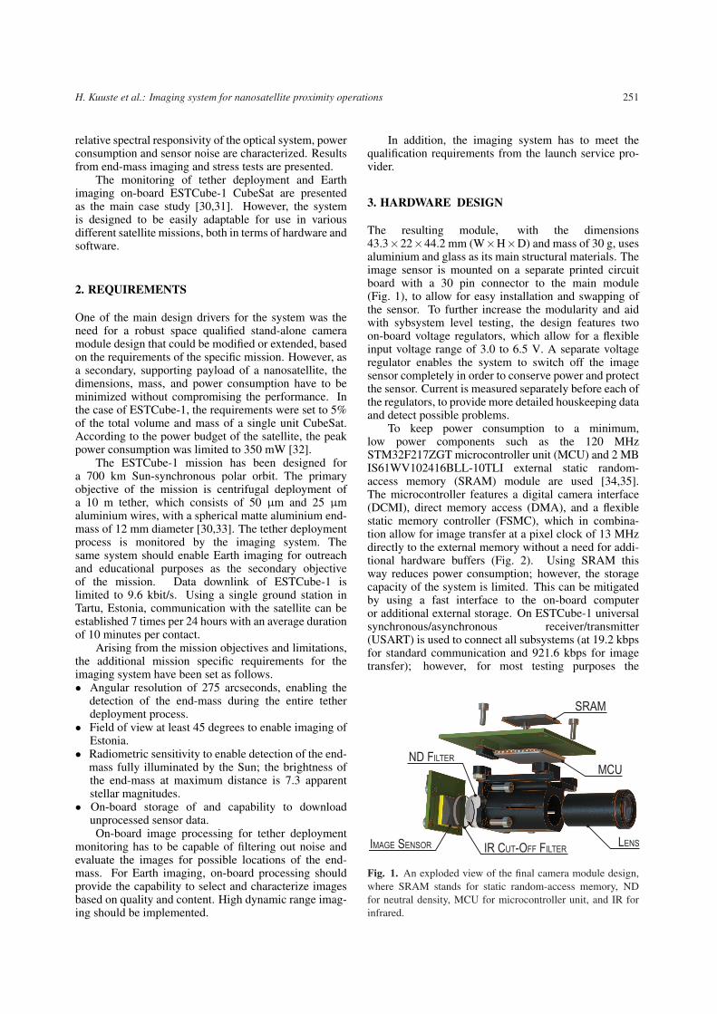
The resulting module, with the dimensions43.3×22×44.2 mm (W×H×D) and mass of 30 g, usesaluminium and glass as its main structural materials. Theimage sensor is mounted on a separate printed circuitboard with a 30 pin connector to the main module(Fig. 1), to allow for easy installation and swapping ofthe sensor. To further increase the modularity and aidwith sybsystem level testing, the design features twoon-board voltage regulators, which allow for a flexibleinput voltage range of 3.0 to 6.5 V. A separate voltageregulator enables the system to switch off the imagesensor completely in order to conserve power and protectthe sensor. Current is measured separately before each ofthe regulators, to provide more detailed houskeeping dataand detect possible problems.
To keep power consumption to a minimum,low power components such as the 120 MHzSTM32F217ZGT microcontroller unit (MCU) and 2 MBIS61WV102416BLL-10TLI external static random-access memory (SRAM) module are used [34,35].The microcontroller features a digital camera interface(DCMI), direct memory access (DMA), and a flexiblestatic memory controller (FSMC), which in combina-tion allow for image transfer at a pixel clock of 13 MHzdirectly to the external memory without a need for addi-tional hardware buffers (Fig. 2). Using SRAM thisway reduces power consumption; however, the storagecapacity of the system is limited. This can be mitigatedby using a fast interface to the on-board computeror additional external storage. On ESTCube-1 universalsynchronous/asynchronous receiver/transmitter(USART) is used to connect all subsystems (at 19.2 kbpsfor standard communication and 921.6 kbps for imagetransfer); however, for most testing purposes the
LENS
MCU
SRAM
IR CUT-OFF FILTERIMAGE SENSOR
ND FILTER
Fig. 1. An exploded view of the final camera module design,where SRAM stands for static random-access memory, NDfor neutral density, MCU for microcontroller unit, and IR forinfrared.

252 Proceedings of the Estonian Academy of Sciences, 2014, 63, 2S, 250–257
� � � � � � � � � � � � � � � � � � � � � � � � � � � � � � � � � � � � � � �� � � � � � � �! � � " � � � " � � � # $ � �� % � � � �& '(()*+ )*++ ), ) - )*+./ *0121, 3( 4 � � 4 � " # � 5 � � � � �6 7 8 9 : � ; < �= > ? @A B �C � < ; DD � � � � � � � � � �� � � � # �< 4 �
� � � � � � � � � � � � �� � � � � � � �E � � � � � � A F G6 7 8 9 : 6 7 8 9 :� ; < �= > H = �I � � � � � � � � � � � � � " �D � � J J � �K L # # �M � � � � L � � �
4 � <4 � � AA B � D � � � � � � � � � � � � � � # �A B �NO P/ *Q'**3Q, 'R S # $ � T � # � # � � � � J � � � � # �6 7 8 9 : U VWXYN VNY � � G �A � � J � � � � � # �Z )R).. 3. / *, 3R[ )Q3A B �\ 7 \ :\ 7 \ : \ 7 \ :Fig. 2. Electrical hardware block diagram of ESTCube-1 on-board camera, where DC-DC stands for direct current to directcurrent, SRAM for static random access memory, FRAM for ferroelectric random access memory, I2C for inter-integrated circuit,I/O for input/output, FSMC for flexible static memory controller, DMA for direct memory access, DCMI for digital camerainterface, ADC for analogue to digital converter, USART for universal synchronous/asynchronous receiver/transmitter, and CMOSfor complementary metal-oxide-semiconductor.
universal serial bus (USB) interface was used due to itsfaster transfer rates of up to 12 Mbps [36]. In addition tothe SRAM, a small 16 kB external ferroelectric randomaccess memory (FRAM) module is used to store criticaldata and settings for the camera.
Based on temperature readings from other satellitesand thermal simulations, the components of the systemhave been chosen to operate within the –20 to +60 ◦Crange, and the system was tested with a range of–35 to +75 ◦C. For reference the design features aninternal temperature sensor in the MCU and an externaltemperature sensor behind the imaging sensor. Bothsensors were calibrated to an accuracy of ±1 ◦C.
For the ESTCube-1 mission, a 4.4 mm telecentriclens with a standard M12x0.5 thread, 9 mm aperture anda depth of field of 0.4 to ∞ m is used. In combinationwith the 640×480 Aptina MT9V011 image sensor [37],this gives a resolution of 262 arcseconds per pixel and afield of view of 46×35 degrees.
For Earth imaging purposes, a 700 nm infrared cut-off filter was included, because the Bayer filter on theimage sensor is effectively transparent at near-infraredwavelengths. An additional 25% neutral density filterwas used to mitigate the potential overexposure of theEarth. The aluminium optics housing was designed toenclose the MCU for a compact design and also for anadditional layer of protection from radiation (Fig. 1).
4. SOFTWARE DESIGN
A general overview of the ESTCube-1 camera systemfirmware is given in Fig. 3. Custom image processingsoftware is used in both of the ESTCube-1 missionobjectives. Images directly from the sensor are storedwith a bit depth of 16 bits resulting in an image sizeof 600 kB. During Earth imaging the data is scaledand compressed to create small 1.5 kB lossy thumbnailsthat can be downloaded in about 5 s. Progressive tolossless compression methods are used on the full imagesto reduce image size, while retaining full fidelity andallowing for partial image downloads. Image evaluationis performed to measure contrast, hue and histogramdistribution; these metrics can be used to discard imagesduring the capture process as well as to aid the satelliteoperator in image selection for download. On-boardalgorithms are used to combine multiple 10 bit imagesat different exposures into a single 16 bit high dynamicrange image.
For end-mass and tether imaging, basic isolatedbright area detection is performed and the coordinatesof possible end-mass locations are stored for retrieval.Either the average or median of multiple images iscalculated to mitigate the effects of random noiseduring the detection process. Lossless compressionis used to reduce the on-board storage requirements.Flexible bit-depth (between 1 to 10 bit) full-frame video

H. Kuuste et al.: Imaging system for nanosatellite proximity operations 253� � � � � � � � � � � � � � � � � �� � � � � � � � � � � � � � � � � � � � �� � ! " # $ % & ' ( % ) � * + ( " ), - , " ) &. � , " / & $ % & ' ( % ) � * + ( " ), - , " ) &0 1 2 3 4 5 6 5 7 8 9: ; < 6 8 = 2 1 0 > ? @ A % / B % ( & C / + )D 7 5 5 E = F G 2 < F 7 =F = < 6 8 H 2 G 6 I 2 G J K 8 7 E = L < 2 3 J 3 D 2 5 6 8 2G 7 = < 8 7 1 : ; < 6 8 = 2 1 > ? @> ? @ M N O P Q Q R O S T O U V W XY W N Z [ Q \ \ V W X] _a bcdeaffg hi j k l m n o p q k rl s n o p q k rl s n o p q k rl s n o p q k rt]uvg _afr w p x y z { | } ~ � ~ p� ~ w } p n ~ w p| ~ � ~ } w p { }� S O \ � � V S Q \ � \ U Q N
� p w p � � } ~ � { } p o � |� � � � � � � �
� � � � � � � �Fig. 3. General overview of ESTCube-1 on-board camera firmware, where darker blocks indicate software shared with the on-boardcomputer system [38].
capture is used during the early phases of the tetherdeployment, to record any possible problems. Due tothe current hardware and software configuration, videocapture frame rates are limited by available SRAM andtransfer speeds to the command and data handling system(CDHS).
Since the system features a capable processor, whichis not in use for long periods of time, the camera sub-system can be used to support data processing for othersubsystems. On ESTCube-1, the camera system also pro-vides lossless data compression capabilities for telemetrydata, collected by the CDHS [38].
To control the imaging, configuration data, andinitial set-up commands are sent to the camera over thecommunication interface. After this, the camera waits foreither a trigger command or an interrupt on a dedicatedhardware input. Giving the camera time to stabilize priorto use and triggering with the hardware interrupt enablesan external system to have precise control over capturetiming.
Software updates can be performed in-orbit using acustom bootloader. The bootloader features 3 indepen-dent slots for firmware images, with one slot designatedas a fallback in case a newer version of the firmwarefails. Commands for the bootloader are stored in externalFRAM. As a contingency system, it is possible to loadthe built-in bootloader of the STM32 MCU by holdingthe hardware trigger line in an active state during startup.The built-in bootloader allows full access to the internalflash memory.
To detect and recover from failures, the softwarefeatures custom exception handling and an independentwatchdog timer. A software controlled heartbeat signalis sent to the electrical power subsystem (EPS) [32] to
indicate that the main task scheduling of the FreeRTOSoperating system is working. As an additional check, theEPS sends out periodic ping commands to all subsystemsto verify the integrity of the communication link.
5. CHARACTERIZATION AND TESTING
5.1. Relative spectral responsivity
The relative spectral responsivity of the fully assembledimaging system was measured from 400 to 900nm with1 nm step using a calibrated SDL1 monochromator witha 1000 W FEL lamp. At each measured wavelength, thevalues of each Bayer filter array channel were averagedover an area of 100 pixels of uniform irradiance. Therelative spectral responsivity curves are shown in Fig. 4.
Fig. 4. Relative spectral response of the assembled opticalsystem.

254 Proceedings of the Estonian Academy of Sciences, 2014, 63, 2S, 250–257
5.2. Power consumption
Power consumption has been characterized by measuringvoltage drop across a shunt resistor using an oscilloscopewith an average expanded uncertainty of 15 mW(coverage factor k = 2). The results (Fig. 5) show anaverage power consumption of 115 mW when idle withall peripherals switched on (stage 5) and a peak powerconsumption of 280 mW during image capture (stage 7).
5.3. Thermal noise characteristics of the CMOSsensor
Image sensor thermal noise tests have been performed ina temperature chamber in the range of –30 to +70 ◦C.The sensor was covered to block all light. Ten images,with an exposure of 1 s, were taken at 10±1 ◦C intervalsafter a stabilization period of 15 min. A time delay of15 s was used between capturing each image, to avoidthe effects of residual signals. The results of thesetests are summarized in Fig. 6. The results measured attemperatures below –10 ◦C are not shown in the figure,since the thermal noise signal was not distinguishablefrom the read-out noise around the bias level of 42analogue to digital units (ADU). The dark frames fromthese tests can be used during image processing toremove bias level and hot pixels.
5.4. Tether end-mass imaging
Tether end-mass imaging tests have been done inlaboratory conditions by suspending the aluminium end-mass from a piece of tether at various distances from the
Fig. 5. Power consumption of the ESTCube-1 camera modulein different operating stages: (1) reset; (2) processor initializa-tion; (3) peripheral initialization; (4) image sensor initializa-tion; (5) idle; (6) preparation for imaging; (7) image capture;(8) standby. The periodic peaks during stages (3) and (4) arecaused by the analogue to digital converters measuring tem-peratures and current consumption. Stages of camera operationhave been delayed in time in order to make the transitions moredistinguishable on the graph.
Fig. 6. Image sensor average dark pixel value (solid line) andmaximum pixel value (dashed line) during temperature tests.Dark frames taken at 1 s exposure. Results presented inanalogue to digital units (ADU).
camera. The tether and end-mass were lit from the sideby a light source that provided Sun-equivalent irradiance.The results (Fig. 7) show that the camera is able to clearlysee not only the end-mass, but also the tether.
5.5. Stress tests
Heat transfer stress tests have been performed in avacuum chamber. For this the camera was running in acontinuous image acquisition loop and the temperature ofthe MCU, external SRAM, and the PCB were measuredat a frequency of 2 Hz. Over several hours the MCUtemperature stabilized at about 5 ◦C higher than theinitial temperature, SRAM at about 7 ◦C higher and thePCB temperature was raised by 2 ◦C.
Long-term reliability tests have been performed byconnecting the camera directly to a computer and lettingit run various image capture modes for several weeks,logging both image data and housekeeping data. To stress
� � � � 35
64
128
256
512
1023
Fig. 7. Tether and end-mass imaging tests with Sun-equivalentirradiance. Images were taken at different distances with anexposure time of 10 ms: (1) 1 m, tether only; (2) 1 m; (3) 4 m;(4) 8 m. Images are in a logarithmic scale, magnified to showindividual pixels and inverted for printing purposes.
H. Kuuste et al.: Imaging system for nanosatellite proximity operations 255
test the custom bootloader, thousands of firmware imageswere uploaded to the camera. No problems were detectedduring the tests.
Vibration tests at a maximum of 22.5 g and shocktests at a maximum of 1410 g have been performedas part of the system level qualification tests [30]. Thecamera subsystem passed the tests without any problems.
6. DISCUSSION AND CONCLUSIONS
A small and robust imaging system for CubeSatproximity operations has been developed, tested, andcharacterized for use in the ESTCube-1 mission.
The system uses low power COTS componentsfor a cost-effective and reusable design. By includinga 120 MHz processor, it is possible for the cameramodule to do much of its own image processing andcompression. In addition it can provide data processingand compression capabilities to external systems, sinceusually the camera itself is not in constant use. Severalsoftware features have been included to allow for errorhandling and firmware upgrades in orbit. This enablesin-orbit testing of new algorithms in the future.
The imaging system fully meets the power require-ments of ESTCube-1. It would be possible to furtherlower the power consumption of the system, variouslevels of standby states can be used, where differentperipherals are switched off, to the point where the MCUand external memory are only powered to retain datawhile the CDHS is not ready to receive it.
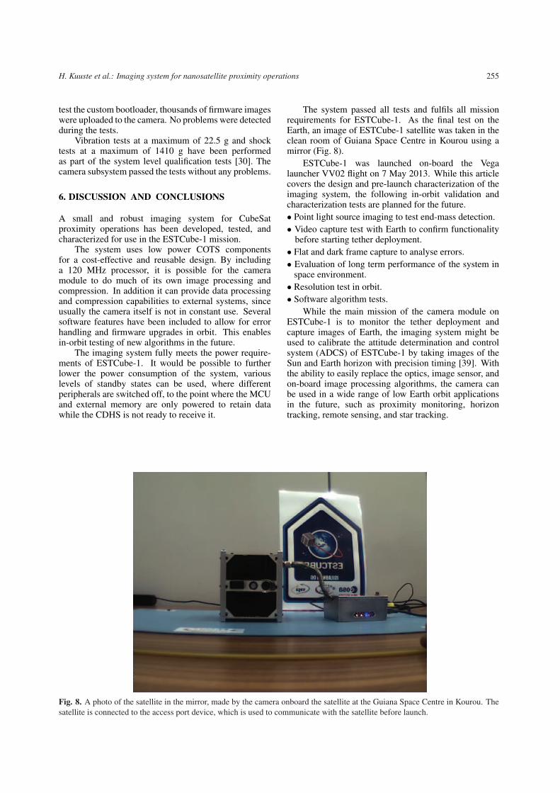
The system passed all tests and fulfils all missionrequirements for ESTCube-1. As the final test on theEarth, an image of ESTCube-1 satellite was taken in theclean room of Guiana Space Centre in Kourou using amirror (Fig. 8).
ESTCube-1 was launched on-board the Vegalauncher VV02 flight on 7 May 2013. While this articlecovers the design and pre-launch characterization of theimaging system, the following in-orbit validation andcharacterization tests are planned for the future.• Point light source imaging to test end-mass detection.• Video capture test with Earth to confirm functionality
before starting tether deployment.• Flat and dark frame capture to analyse errors.• Evaluation of long term performance of the system in
space environment.• Resolution test in orbit.• Software algorithm tests.
While the main mission of the camera module onESTCube-1 is to monitor the tether deployment andcapture images of Earth, the imaging system might beused to calibrate the attitude determination and controlsystem (ADCS) of ESTCube-1 by taking images of theSun and Earth horizon with precision timing [39]. Withthe ability to easily replace the optics, image sensor, andon-board image processing algorithms, the camera canbe used in a wide range of low Earth orbit applicationsin the future, such as proximity monitoring, horizontracking, remote sensing, and star tracking.
Fig. 8. A photo of the satellite in the mirror, made by the camera onboard the satellite at the Guiana Space Centre in Kourou. Thesatellite is connected to the access port device, which is used to communicate with the satellite before launch.

256 Proceedings of the Estonian Academy of Sciences, 2014, 63, 2S, 250–257
ACKNOWLEDGEMENTS
The authors would like to thank everybody who hasworked on the ESTCube project. Special thanks go toAndreas Valdmann (University of Tartu) for helping withoptics testing. We would also thank Aivo Reinart (TartuObservatory) and Anu Reinart (Tartu Observatory) for allthe support.
This research has been supported by the EuropeanSpace Agency, Estonian Ministry of Economic Affairsand Communication, and Enterprise Estonia.
REFERENCES
1. CubeSat Design Specification Revision 12. California StatePolytechnic University, 2009.
2. Ansdell, M., Ehrenfreund, P., and McKay, C. Step-ping stones toward global space exploration. ActaAstronaut., 2011, 68, 2098–2113.
3. Ehrenfreund, P., McKay, C., Rummel, J. D., Foing, B. H.,Neal, C. R., Masson-Zwaan, T. et al. Toward aglobal space exploration program: A stepping stoneapproach. Adv. Space Res., 2012, 49, 2–48.
4. Bouwmeester, J. and Guo, J. Survey of worldwide pico-and nanosatellite missions, distributions and sub-system technology. Acta Astronaut., 2010, 67, 854–862.
5. Woellert, K., Ehrenfreund, P., Ricco, A. J., and Hertz-feld, H. Cubesats: Cost-effective science and technol-ogy platforms for emerging and developing nations.Adv. Space Res., 2011, 47, 663–684.
6. Selva, D. and Krejci, D. A survey and assessment of thecapabilities of Cubesats for Earth observation. ActaAstronaut., 2012, 74, 50–68.
7. Shiroma, W. A., Martin, L. K., Akagi, J. M., Akagi, J. T.,Wolfe, B. L., Fewell, B. A. et al. CubeSats: A brightfuture for nanosatellites. Cent. Eur. J. Eng., 2011, 1,9–15.
8. Shimizu, K. University of Tokyo nano satellite project“PRISM”. In Proc. 27th Int. Symp. on Space Technol.and Sci., 2009, 4–9.
9. Tsuda, Y., Sako, N., Eishima, T., Ito, T., Arikawa, Y.,Miyamura, N. et al. University of Tokyo’sCubeSat project – its educational and technologicalsignificance. In Proc. 15th Annual AIAA/USU Confer.on Small Satellites, 2001, 13–16.
10. Tsuda, Y., Sako, N., Eishima, T., Ito, T., Arikawa, Y.,Miyamura, N. et al. University of Tokyo’s CubeSat“XI” as a student-built educational pico-satellite –Final design and operation plan. In Proc. 23rd Int.Symp. of Space Technol. and Sci., 2002, vol. 2, 1372–1377.
11. Kurtulus, C., Baltaci, T., Ulusoy, M., Aydm, B. T.,Tutkun, B., Inalhan, G. et al. iTU-pSAT I: IstanbulTechnical University Student Pico-Satellite program.
In Proc. IEEE 3rd Int. Confer. on Recent Adv. SpaceTechnol. RAST’07., 2007, 725–732.
12. Rankin, D., Kekez, D. D., Zee, R. E., Pranajaya, F. M.,Foisy, D. G., and Beattie, A. M. The CanX-2 nano-satellite: Expanding the science abilities of nano-satellites. Acta Astronaut., 2005, 57, 167–174.
13. Scholz, A., Giesselmann, J., and Duda, C. CubeSattechnical aspects. In Proc. 55th Int. Astronaut. Congr.,2004.
14. Scholz, A., Ley, W., Dachwald, B., Miau, J. J., andJuang, J. C. Flight results of the COMPASS-1 pico-satellite mission. Acta Astronaut., 2010, 67, 1289–1298.
15. Ashida, H., Fujihashi, K., Inagawa, S., Miura, Y.,Omagari, K., Miyashita, N. et al. Design of TokyoTech nanosatellite Cute-1.7+APD II and its operation.Acta Astronaut., 2010, 66, 1412–1424.
16. Stras, L., Kekez, D. D., Wells, G. J., Jeans, T., Zee, R. E.,Pranajaya, F. M. et al. The design and operation of theCanadian advanced nanospace eXperiment (CanX-1). In Proc. AMSAT-NA 21st Space Symp., Toronto,Canada. 2003, 150–160.
17. Sarda, K., Eagleson, S., Caillibot, E., Grant, C., Kekez, D.,Pranajaya, F. et al. Canadian advanced nanospaceexperiment 2: Scientific and technological innovationon a three-kilogram satellite. Acta Astronaut., 2006,59, 236–245.
18. Deschamps, N. C., Grant, C. C., Foisy, D. G., Zee, R. E.,Moffat, A. F. J., and Weiss, W. W. The BRITEspace telescope: Using a nanosatellite constellation tomeasure stellar variability in the most luminous stars.Acta Astronaut., 2009, 65, 643–650.
19. Koudelka, O., Egger, G., Josseck, B., Deschamp, N.,Cordell Grant, C., Foisy, D. et al. TUGSAT-1/BRITE-Austria – The first Austrian nanosatellite. ActaAstronaut., 2009, 64, 1144–1149.
20. Taraba, M., Rayburn, C., Tsuda, A., and MacGillivray, C.Boeing’s CubeSat TestBed 1 attitude determinationdesign and on-orbit experience. In Proc. AIAA/USUConfer. on Small Satellites, 2009.
21. Miyashita, N., Iai, M., Omagari, K., Imai, K., Yabe, H.,Miyamoto, K. et al. Development of nano-satelliteCute-1. 7 + APD and its current status. In 56th Int.Astronaut. Congr., 2005.
22. Tsuda, Y., Mori, O., Funase, R., Sawada, H.,Yamamoto, T., Saiki, T. et al. Flight status of IKAROSdeep space solar sail demonstrator. Acta Astronaut.,2011, 69, 833–840.
23. Tanaka, T., Kawamura, Y., and Tanaka, T. Overviewand operations of CubeSat FITSAT-1 (NIWAKA). InProc. 6th International Confer. on Recent Advances inSpace Technologies, 2013.
24. Dickinson, J., DeForest, C., and Howard, T. The CubeSatHeliospheric Imaging Experiment (CHIME). In Proc.Aerospace Confer., 2011 IEEE. 2011, 1–12.

H. Kuuste et al.: Imaging system for nanosatellite proximity operations 257
25. Borgeaud, M., Scheidegger, N., Noca, M., Roethlis-berger, G., Jordan, F., Choueiri, T. et al. SwissCube:The first entirely-built swiss student satellite with anEarth observation payload. In Small Satellite Missionsfor Earth Observation (Sandau, R., Roeser, H. P., andValenzuela, A., eds). Springer, Berlin, Heidelberg,2010, 207–213.
26. Noca, M., Jordan, F., Steiner, N., Choueiri, T., George, F.,Roethlisberger, G. et al. Lessons learned from the firstSwiss pico-satellite: SwissCube. Science, 2009.
27. Bridges, C., Kenyon, S., Underwood, C., Lappas, V.STRaND-1: The world’s first smartphone nano-satellite. In Proc. 2nd International Confer. on SpaceTechnology (ICST), 2011, 1–3.
28. Alminde, L., Bisgaard, M., Vinther, D., Viscor, T., andOstergard, K. Educational value and lessons learnedfrom the AAUCubeSat project. In Proc. InternationalConfer. on Recent Adv. in Space Technol., 2003, 57–62.
29. Alminde, L., Bisgaard, M., Bhanderi, D., and Niel-sen, J. D. Experience and methodology gained from4 years of student satellite projects. In Proc. Interna-tional Confer. on Recent Adv. in Space Technol., 2005,94–99.
30. Latt, S., Slavinskis, A., Ilbis, E., Kvell, U., Voorman-sik, K., Kulu, E. et al. ESTCube-1 nanosatellitefor electric solar wind sail in-orbit technologydemonstration. Proc. Estonian Acad. Sci., 2014,63(2S), 200–209.
31. Janhunen, P., Toivanen, P. K., Polkko, J., Merikallio, S.,Salminen, P., Haeggstrom, E. et al. Invited Article:Electric solar wind sail: Toward test missions. Rev.Sci. Instrum., 2010, 81, 111301–111311.
32. Pajusalu, M., Ilbis, E., Ilves, T., Veske, M., Kalde, J., Lill-maa, H. et al. Design and pre-flight testing of theelectrical power system for the ESTCube-1 nanosatel-lite. Proc. Estonian Acad. Sci., 2014, 63(2S), 232–241.
33. Envall, J., Janhunen, P., Toivanen, P., Pajusalu, M.,Ilbis, E., Kalde, J. et al. E-sail test payload of theESTCube-1 nanosatellite. Proc. Estonian Acad. Sci.,2014, 63(2S), 210–221.
34. STMicroelectronics. DS6697: ARM-based 32-bit MCU,150DMIPs, up to 1MB Flash/128+4KB RAM, crypto,USB OTG HS/FS, Ethernet, 17 TIMs, 3 ADCs,15 comm. interfaces & camera; 2011. http://www.st.com./web/en/resource/technical/document/datasheet/CD00263874.pdf
35. Integrated Silicon Solution, Inc. IS61WV102415BLL.1M x 16 High-speed asynchronous CMOS staticRAM with 3.3 V supply; 2006. http://www.issi.com./ww/pdf/61WV102415ALL.pdf
36. USB Implementers Forum, Inc. Universal Serial BusSpecification Revision 2.0; 2000. http://www.usb.org/developers/docs/usb20 docs
37. Aptina Imaging Corporation. MT9V011: 1/4-Inch VGADigital Image Sensor; 2009.
38. Laizans, K., Sunter, I., Zalite, K., Kuuste, H., Valgur, M.,Tarbe, K. et al. Design of the fault tolerant commandand data handling subsystem for ESTCube-1. Proc.Estonian Acad. Sci., 2014, 63(2S), 222–231.
39. Slavinskis, A., Kulu, E., Viru, J., Valner, R., Ehrpais, H.,Uiboupin, T. et al. Attitude determination andcontrol for centrifugal tether deployment on theESTCube-1 nanosatellite. Proc. Estonian Acad. Sci.,2014, 63(2S), 242–249.
Kaamerasusteem nanosatelliitide lahioperatsioonide jalgimiseks
Henri Kuuste, Tonis Eenmae, Viljo Allik, Ants Agu, Riho Vendt, Ilmar Ansko, Kaspars Laizans,Indrek Sunter, Silver Latt ja Mart Noorma
On kasitletud uudse lahendusega nanosatelliitide lahioperatsioonide jalgimiseks sobivat kaamerasusteemi ja selletestimist. Seda kaamerasusteemi on tulevikus voimalik kohaldada paljude erinevate satelliidimissioonide tarbeks.Artiklis kirjeldatud modifikatsioon lahtub ESTCube-1 missiooni nouetest ja piirangutest. ESTCube-1 missioonikaigus on pardakaamera pohieesmarkideks jaadvustada 10-meetrise juhtme valjakerimist satelliidist ja pildistadaMaad teaduse populariseerimise eesmarkidel.
Kaamerasusteem pohineb ARM Cortex-M3 mikrokontrolleril ja kiirel staatilisel muutmalul. Susteem on moo-tudega 43,3×22×44,2 mm ja kaalub 30 g. Voolutarve on keskmiselt 118 mW. Maksimaalne voolutarve 280 mWesineb pildi salvestamise hetkel. On tehtud vajalikud kvalifikatsiooni- ja koormustestid ning kaamera on optiliseltkalibreeritud. ESTCube-1 missiooni taitmiseks on kaamerasusteem konfigureeritud 4,4 mm teletsentrilise objektiivija 10-bitise 640×480 CMOS-i pildisensoriga. Kaamera optikas kasutatakse 700 nanomeetrist pikema lainepikkusegainfrapunakiirgust tokestavat filtrit ja 25% labilaskvusega hallfiltrit. Loodud susteemi lahutusvoime on 12,7 mm ja 1 kmpiksli kohta vastavalt kaugustel 10 m ning 700 km. Kaamerasusteemi tarkvara sisaldab piltide hindamise algoritme jasuure dunaamilise ulatusega piltide loomise voimalust.