Imaging of Hip Arthroplasty - geiselmed.dartmouth.edu · Imaging of Hip Arthroplasty Theodore T....
17
Imaging of Hip Arthroplasty Theodore T. Miller, M.D. 1 ABSTRACT Radiography is the mainstay of the imaging evaluation of the prosthetic hip, but arthrography, aspiration, scintigraphy, sonography, computed tomography, and magnetic resonance imaging all have roles in the evaluation of the painful prosthesis. This article reviews the appearance of normal hip arthroplasty as well as the appearances of potential complications. KEYWORDS: Hip, arthroplasty, replacement, complications, imaging, CT, MRI Surgeons have long recognized the concept of replacing the abnormal hip joint, but efforts were ham- pered by the lack of suitable materials and imprecise surgical technique. Primitive attempts at replacing the ankylosed or debilitating arthritic hip in the 1800s used wood, ivory, rubber, and even pig bladders. 1 In the first half of the 20th century, acetabular cups made of Pyrex and Teflon and femoral heads of acrylic cement were tried unsuccessfully. 1–3 In the 1930s, an alloy of cobalt- chromium-molybdenum called Vitallium was discov- ered, 1,2 and cobalt-chrome alloys are one of the metals still used today. The modern era of ‘‘low friction’’ hip arthroplasty began in the 1960s with the work of Sir John Charnley, who pioneered the use of stainless steel metal-on- polyethylene (MOP) prostheses. 4 Many different varia- tions and designs have since been introduced, but most follow his principle of a metal femoral head articulating against a polyethylene socket. Hip arthroplasty has become so successful, with some designs having a 25- year survivorship of almost 80%, 5 that the hip is the most commonly replaced joint, with 500,000 performed each year worldwide. 6 Although radiography is the mainstay of the imaging evaluation of the prosthetic hip, aspiration, arthrography, scintigraphy, sonography, computed tomography (CT), and magnetic resonance (MR) imaging all have roles in the evaluation of the painful prosthesis. This article reviews the appearance of normal hip arthroplasty as well as the appearances of potential complications. NORMAL Hemiarthroplasty refers to replacement of only the femoral side of the hip joint and is usually done for cases of hip fracture or avascular necrosis in which the ace- tabular cartilage is preserved and there is no degenerative arthritis. In a unipolar hemiarthroplasty the prosthetic femoral head articulates directly against the acetabular cartilage (Fig. 1). Over time, however, the articular cartilage wears away, leading to painful degenerative arthritis of the acetabulum. To protect the acetabular cartilage, a bipolar hemiarthroplasty may be performed in which a prosthetic cup is placed into the native acetabulum against which the prosthetic femoral head articulates; the acetabulum is not reamed or prepared, and the cup is not fixed in place (Fig. 2). Thus, some motion of the cup may occur against the acetabular cartilage, also eventually wearing it down. Total hip arthroplasty (THA) in which both the femoral head and the acetabulum are replaced by fixed prosthetic devices, is most often performed for disease processes that have affected both sides of the native joint, such as degenerative and rheumatoid arthritis. An Update on Imaging of Joint Reconstructions; Editors in Chief, David Karasick, M.D., Mark E. Schweitzer, M.D.; Guest Editor, Theodore T. Miller, M.D. Seminars in Musculoskeletal Radiology, Volume 10, Number 1, 2006. Address for correspondence and reprint requests: Theodore T. Miller, M.D., Chief, Division of Musculoskeletal Imaging, Department of Radiology, North Shore University Hospital and Long Island Jewish Medical Center, 825 Northern Blvd., Great Neck, NY 11021. 1 Division of Musculoskeletal Imaging, Department of Radiology, North Shore University Hospital and Long Island Jewish Medical Center, Great Neck, New York. Copyright # 2006 by Thieme Medical Publishers, Inc., 333 Seventh Avenue, New York, NY 10001, USA. Tel: +1(212) 584-4662. 1089-7860,p;2006,10,01,030,046,ftx,en;smr00384x. 30 Downloaded by: Dartmouth College. Copyrighted material.
Transcript of Imaging of Hip Arthroplasty - geiselmed.dartmouth.edu · Imaging of Hip Arthroplasty Theodore T....
Imaging of Hip ArthroplastyTheodore T. Miller, M.D.1
ABSTRACT
Radiography is the mainstay of the imaging evaluation of the prosthetic hip, butarthrography, aspiration, scintigraphy, sonography, computed tomography, and magneticresonance imaging all have roles in the evaluation of the painful prosthesis. This articlereviews the appearance of normal hip arthroplasty as well as the appearances of potentialcomplications.
KEYWORDS: Hip, arthroplasty, replacement, complications, imaging, CT, MRI
Surgeons have long recognized the concept ofreplacing the abnormal hip joint, but efforts were ham-pered by the lack of suitable materials and imprecisesurgical technique. Primitive attempts at replacing theankylosed or debilitating arthritic hip in the 1800s usedwood, ivory, rubber, and even pig bladders.1 In the firsthalf of the 20th century, acetabular cups made of Pyrexand Teflon and femoral heads of acrylic cement weretried unsuccessfully.1–3 In the 1930s, an alloy of cobalt-chromium-molybdenum called Vitallium was discov-ered,1,2 and cobalt-chrome alloys are one of the metalsstill used today.
The modern era of ‘‘low friction’’ hip arthroplastybegan in the 1960s with the work of Sir John Charnley,who pioneered the use of stainless steel metal-on-polyethylene (MOP) prostheses.4 Many different varia-tions and designs have since been introduced, but mostfollow his principle of a metal femoral head articulatingagainst a polyethylene socket. Hip arthroplasty hasbecome so successful, with some designs having a 25-year survivorship of almost 80%,5 that the hip is the mostcommonly replaced joint, with �500,000 performedeach year worldwide.6 Although radiography is themainstay of the imaging evaluation of the prosthetichip, aspiration, arthrography, scintigraphy, sonography,computed tomography (CT), and magnetic resonance(MR) imaging all have roles in the evaluation of the
painful prosthesis. This article reviews the appearanceof normal hip arthroplasty as well as the appearances ofpotential complications.
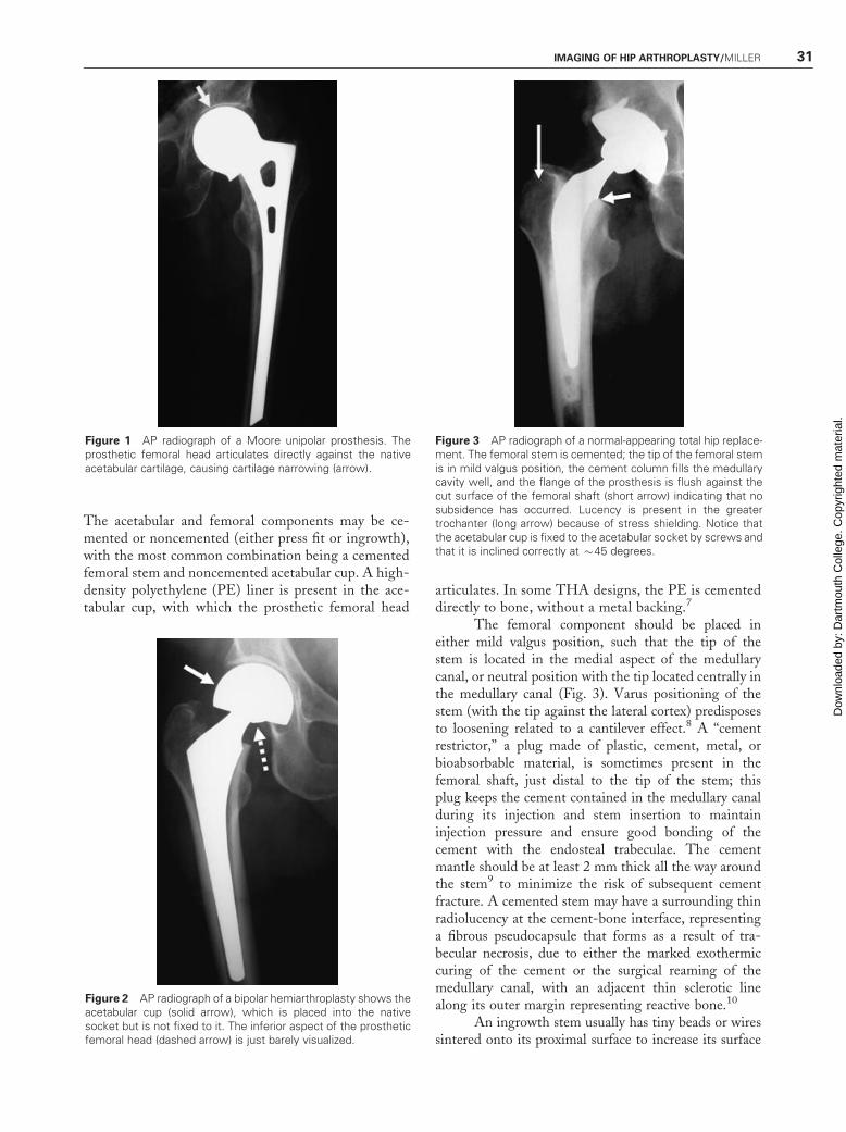
NORMALHemiarthroplasty refers to replacement of only thefemoral side of the hip joint and is usually done for casesof hip fracture or avascular necrosis in which the ace-tabular cartilage is preserved and there is no degenerativearthritis. In a unipolar hemiarthroplasty the prostheticfemoral head articulates directly against the acetabularcartilage (Fig. 1). Over time, however, the articularcartilage wears away, leading to painful degenerativearthritis of the acetabulum. To protect the acetabularcartilage, a bipolar hemiarthroplasty may be performedin which a prosthetic cup is placed into the nativeacetabulum against which the prosthetic femoral headarticulates; the acetabulum is not reamed or prepared,and the cup is not fixed in place (Fig. 2). Thus, somemotion of the cup may occur against the acetabularcartilage, also eventually wearing it down. Total hiparthroplasty (THA) in which both the femoral headand the acetabulum are replaced by fixed prostheticdevices, is most often performed for disease processesthat have affected both sides of the native joint, such asdegenerative and rheumatoid arthritis.
An Update on Imaging of Joint Reconstructions; Editors in Chief, David Karasick, M.D., Mark E. Schweitzer, M.D.; Guest Editor, Theodore T.Miller, M.D. Seminars in Musculoskeletal Radiology, Volume 10, Number 1, 2006. Address for correspondence and reprint requests: Theodore T.Miller, M.D., Chief, Division of Musculoskeletal Imaging, Department of Radiology, North Shore University Hospital and Long Island JewishMedical Center, 825 Northern Blvd., Great Neck, NY 11021. 1Division of Musculoskeletal Imaging, Department of Radiology, North ShoreUniversity Hospital and Long Island Jewish Medical Center, Great Neck, New York. Copyright# 2006 by Thieme Medical Publishers, Inc., 333Seventh Avenue, New York, NY 10001, USA. Tel: +1(212) 584-4662. 1089-7860,p;2006,10,01,030,046,ftx,en;smr00384x.
30
Dow
nloa
ded
by: D
artm
outh
Col
lege
. Cop
yrig
hted
mat
eria
l.
The acetabular and femoral components may be ce-mented or noncemented (either press fit or ingrowth),with the most common combination being a cementedfemoral stem and noncemented acetabular cup. A high-density polyethylene (PE) liner is present in the ace-tabular cup, with which the prosthetic femoral head
articulates. In some THA designs, the PE is cementeddirectly to bone, without a metal backing.7
The femoral component should be placed ineither mild valgus position, such that the tip of thestem is located in the medial aspect of the medullarycanal, or neutral position with the tip located centrally inthe medullary canal (Fig. 3). Varus positioning of thestem (with the tip against the lateral cortex) predisposesto loosening related to a cantilever effect.8 A ‘‘cementrestrictor,’’ a plug made of plastic, cement, metal, orbioabsorbable material, is sometimes present in thefemoral shaft, just distal to the tip of the stem; thisplug keeps the cement contained in the medullary canalduring its injection and stem insertion to maintaininjection pressure and ensure good bonding of thecement with the endosteal trabeculae. The cementmantle should be at least 2 mm thick all the way aroundthe stem9 to minimize the risk of subsequent cementfracture. A cemented stem may have a surrounding thinradiolucency at the cement-bone interface, representinga fibrous pseudocapsule that forms as a result of tra-becular necrosis, due to either the marked exothermiccuring of the cement or the surgical reaming of themedullary canal, with an adjacent thin sclerotic linealong its outer margin representing reactive bone.10
An ingrowth stem usually has tiny beads or wiressintered onto its proximal surface to increase its surface
Figure 1 AP radiograph of a Moore unipolar prosthesis. Theprosthetic femoral head articulates directly against the nativeacetabular cartilage, causing cartilage narrowing (arrow).
Figure 2 AP radiograph of a bipolar hemiarthroplasty shows theacetabular cup (solid arrow), which is placed into the nativesocket but is not fixed to it. The inferior aspect of the prostheticfemoral head (dashed arrow) is just barely visualized.
Figure 3 AP radiograph of a normal-appearing total hip replace-ment. The femoral stem is cemented; the tip of the femoral stemis in mild valgus position, the cement column fills the medullarycavity well, and the flange of the prosthesis is flush against thecut surface of the femoral shaft (short arrow) indicating that nosubsidence has occurred. Lucency is present in the greatertrochanter (long arrow) because of stress shielding. Notice thatthe acetabular cup is fixed to the acetabular socket by screws andthat it is inclined correctly at �45 degrees.
IMAGING OF HIP ARTHROPLASTY/MILLER 31
Dow
nloa
ded
by: D
artm
outh
Col
lege
. Cop
yrig
hted
mat
eria
l.
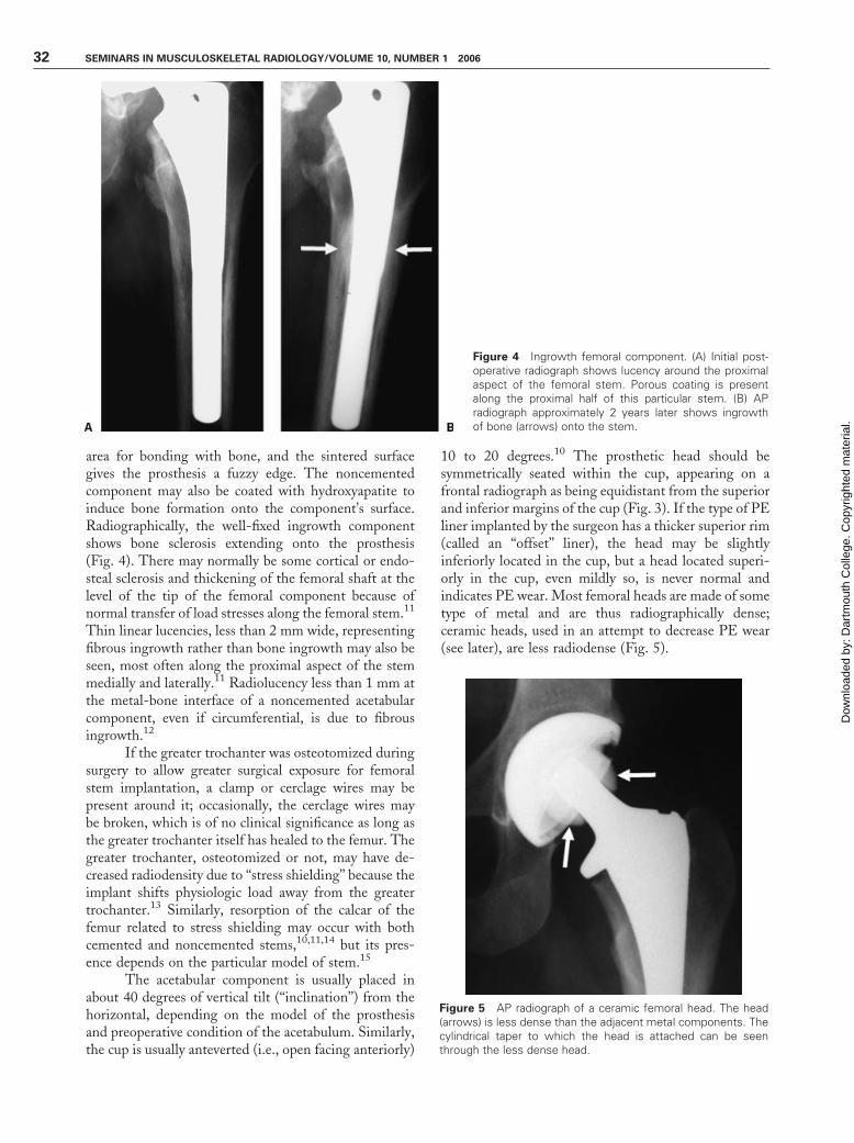
area for bonding with bone, and the sintered surfacegives the prosthesis a fuzzy edge. The noncementedcomponent may also be coated with hydroxyapatite toinduce bone formation onto the component’s surface.Radiographically, the well-fixed ingrowth componentshows bone sclerosis extending onto the prosthesis(Fig. 4). There may normally be some cortical or endo-steal sclerosis and thickening of the femoral shaft at thelevel of the tip of the femoral component because ofnormal transfer of load stresses along the femoral stem.11
Thin linear lucencies, less than 2 mm wide, representingfibrous ingrowth rather than bone ingrowth may also beseen, most often along the proximal aspect of the stemmedially and laterally.11 Radiolucency less than 1 mm atthe metal-bone interface of a noncemented acetabularcomponent, even if circumferential, is due to fibrousingrowth.12
If the greater trochanter was osteotomized duringsurgery to allow greater surgical exposure for femoralstem implantation, a clamp or cerclage wires may bepresent around it; occasionally, the cerclage wires maybe broken, which is of no clinical significance as long asthe greater trochanter itself has healed to the femur. Thegreater trochanter, osteotomized or not, may have de-creased radiodensity due to ‘‘stress shielding’’ because theimplant shifts physiologic load away from the greatertrochanter.13 Similarly, resorption of the calcar of thefemur related to stress shielding may occur with bothcemented and noncemented stems,10,11,14 but its pres-ence depends on the particular model of stem.15
The acetabular component is usually placed inabout 40 degrees of vertical tilt (‘‘inclination’’) from thehorizontal, depending on the model of the prosthesisand preoperative condition of the acetabulum. Similarly,the cup is usually anteverted (i.e., open facing anteriorly)
10 to 20 degrees.10 The prosthetic head should besymmetrically seated within the cup, appearing on afrontal radiograph as being equidistant from the superiorand inferior margins of the cup (Fig. 3). If the type of PEliner implanted by the surgeon has a thicker superior rim(called an ‘‘offset’’ liner), the head may be slightlyinferiorly located in the cup, but a head located superi-orly in the cup, even mildly so, is never normal andindicates PE wear. Most femoral heads are made of sometype of metal and are thus radiographically dense;ceramic heads, used in an attempt to decrease PE wear(see later), are less radiodense (Fig. 5).
Figure 4 Ingrowth femoral component. (A) Initial post-operative radiograph shows lucency around the proximalaspect of the femoral stem. Porous coating is presentalong the proximal half of this particular stem. (B) APradiograph approximately 2 years later shows ingrowthof bone (arrows) onto the stem.
Figure 5 AP radiograph of a ceramic femoral head. The head(arrows) is less dense than the adjacent metal components. Thecylindrical taper to which the head is attached can be seenthrough the less dense head.
32 SEMINARS IN MUSCULOSKELETAL RADIOLOGY/VOLUME 10, NUMBER 1 2006
Dow
nloa
ded
by: D
artm
outh
Col
lege
. Cop
yrig
hted
mat
eria
l.

The rim of the PE liner is usually flush with the rim ofthe metal cup, but sometimes additional mechanicalconstraint is needed, such as for patients with poortissue elasticity in whom recurrent dislocation of thefemoral head is a problem because the soft tissues aretoo lax to maintain the head within a standard cup. Inthis group of patients, a constrained liner extendsbeyond the cup itself, to deepen the articulation andlimit the range of motion. Lastly, during reaming of theacetabular socket in preparation for cup placement, themedial wall is occasionally breached. To prevent ce-ment from leaking into the pelvic cavity, where itsexothermic curing can be damaging to vessels, nerves,and pelvic organs, a small metal mesh, resembling a hat,is placed into the bone defect to contain the cementwithin the acetabulum.
COMPLICATIONSComplications of total hip arthroplasty can be groupedinto aseptic loosening and osteolysis, dislocation, infec-tion, periprosthetic fracture, hardware failure, and het-erotopic ossification.
Aseptic Loosening and Osteolysis
Aseptic loosening of the prosthesis is the most commonreason for revision surgery.9,16 Radiographic appearancesof loosening of a cemented femoral prosthesis arelucency at the cement-bone interface of more than2 mm surrounding the component, progressive wideningof the lucency at the cement-bone interface (Fig. 6),lucency at the metal-cement interface,17 and fracture ofthe cement mantle. The orthopedic classification formodes of stem failure is listed in Table 1. Radiographicappearances of loosening of a noncemented femoralprosthesis are lucency at the metal-bone interface greaterthan 2 mm surrounding the component, development orwidening of the lucency at the metal-bone interface, andsubsidence of more than 1 cm and/or which continues toprogress more than 1 year after placement.10,18 Sheddingof surface beads can be seen with both loose and stableimplants.19,20 The radiographic appearance of looseningof cemented and noncemented acetabular components islucency greater than 2 mm at the cement-bone or metal-bone interface around its entire circumference.12,21,22
Additional radiographic features of loosening, regardlessof whether the components are femoral or acetabular orcemented or noncemented, are migration of the compo-nent or change of position of the component, fracture ofthe component, and component motion with stressviews.17,23 Review of previous radiographs is necessaryto detect subtle serial change.24
The description of the location of the lucenciesshould follow the standard orthopedic descriptions offemoral and acetabular ‘‘zones’’ (Fig. 7): there are seven
femoral zones on the anteroposterior (AP) radiograph,with the first three numbered from proximal to distalalong the lateral aspect of the stem, zone 4 at the tip ofthe stem, and zones 5 to 7 numbered from distal toproximal along the medial aspect of the stem.8 There arean additional seven zones on the lateral radiograph,numbered 8 through 14, beginning at the anteroprox-imal aspect of the femoral stem. The region around theacetabular component is divided into three equal zones,I, II, III, from lateral to medial around the periphery ofthe cup.21
Arthrography is still occasionally performedto evaluate suspected loosening of an implant. The
Figure 6 Progressive lucency due to loosening. (A) Initial APradiograph shows a cemented stem inmild valgus position. A thinradiolucency is present at the cement bone interface laterally andproximal-medially because of the normal fibrous capsule thatforms due to the curing of the cement. (B) AP radiograph �2years later shows the development of radiolucency (arrows)around the entire cement mantle. The lucency is irregular andfocally wide, particularly at the tip.
Table 1 Modes of Failure of Cemented Stems8
Mode I. Pistoning (up-and-down motion)
A. Pistoning of the stem within the cement mantle.
B. Pistoning of the stem and cement mantle within
the medullary canal.
Mode II. Medial midstem pivot (medial migration of proximal
stem and lateral migration of stem tip)
Mode III. Calcar pivot (medial-lateral toggling of the stem tip,
analogous to the "windshield wiper" phenomenon of
uncemented stems)
Mode IV. Bending cantilever fatigue (medial migration of the
proximal stem with distal fixation of the stem) Often
the result of initial varus positioning of the stem.
IMAGING OF HIP ARTHROPLASTY/MILLER 33
Dow
nloa
ded
by: D
artm
outh
Col
lege
. Cop
yrig
hted
mat
eria
l.
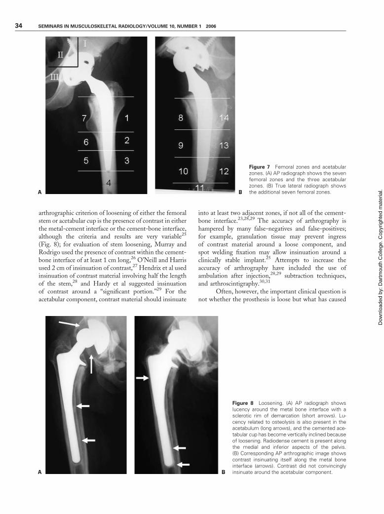
arthrographic criterion of loosening of either the femoralstem or acetabular cup is the presence of contrast in eitherthe metal-cement interface or the cement-bone interface,although the criteria and results are very variable25
(Fig. 8); for evaluation of stem loosening, Murray andRodrigo used the presence of contrast within the cement-bone interface of at least 1 cm long,26 O’Neill and Harrisused 2 cm of insinuation of contrast,27 Hendrix et al usedinsinuation of contrast material involving half the lengthof the stem,28 and Hardy et al suggested insinuationof contrast around a ‘‘significant portion.’’29 For theacetabular component, contrast material should insinuate
into at least two adjacent zones, if not all of the cement-bone interface.23,28,29 The accuracy of arthrography ishampered by many false-negatives and false-positives;for example, granulation tissue may prevent ingressof contrast material around a loose component, andspot welding fixation may allow insinuation around aclinically stable implant.25 Attempts to increase theaccuracy of arthrography have included the use ofambulation after injection,28,29 subtraction techniques,and arthroscintigraphy.30,31
Often, however, the important clinical question isnot whether the prosthesis is loose but what has caused
Figure 7 Femoral zones and acetabularzones. (A) AP radiograph shows the sevenfemoral zones and the three acetabularzones. (B) True lateral radiograph showsthe additional seven femoral zones.
Figure 8 Loosening. (A) AP radiograph showslucency around the metal bone interface with asclerotic rim of demarcation (short arrows). Lu-cency related to osteolysis is also present in theacetabulum (long arrows), and the cemented ace-tabular cup has become vertically inclined becauseof loosening. Radiodense cement is present alongthe medial and inferior aspects of the pelvis.(B) Corresponding AP arthrographic image showscontrast insinuating itself along the metal boneinterface (arrows). Contrast did not convincinglyinsinuate around the acetabular component.
34 SEMINARS IN MUSCULOSKELETAL RADIOLOGY/VOLUME 10, NUMBER 1 2006
Dow
nloa
ded
by: D
artm
outh
Col
lege
. Cop
yrig
hted
mat
eria
l.

the loosening. The most common cause is mechanicalloosening, but osteolysis related to ‘‘particle disease’’ andinfection can also look similar. Any of the components ofa hip replacement, such as the metal, PE liner, orcement, can become microscopically fragmented becauseof wear, shedding small particles of material that caninduce a histiocytic inflammatory reaction,32–36 but theacetabular PE is the most common source because it isconstantly worn against the metal femoral head, anexample of abrasive wear (Table 2). In some cup designswith poor locking of the PE liner into the cup, wear ofthe inner surface of the PE related to micromotionagainst the cup produces so-called backside wear.37,38
Moreover, PE wear can be accelerated by third-partyabrasion because of metal or cement fragments in ce-mented THAs or shed beads or hydroxyapatite granulesin noncemented THAs39 (Table 3). The average PEwear rate of MOP designs is about 100 to 200 m/year.40
The particles are engulfed by macrophages, which thenrelease various factors and cytokines, such as interleu-kins, prostaglandins, and tumor necrosis factor. Thecytokines attract other inflammatory cells and stimulateosteoclastic activity, leading to osteolysis.32,33,41
Osteolysis related to particle disease is suggestedradiographically by focal well-defined radiolucenciesaround either the acetabular or femoral compo-nents13,23,42 (Fig. 9). The presence of osteolysis at sitesaway from the actual articulating surfaces of the arthro-plasty is explained by the concept of the ‘‘effective jointspace,’’43 which states that joint fluid (and the particulatedebris contained therein) may insinuate itself around
both the femoral and acetabular components because ofthe hydrostatic pressure generated by joint movement;thus, for example, screw holes in acetabular componentsor the screw tracts themselves provide an avenue forparticulate debris to reach pelvic bone. Although radio-graphic evaluation of osteolytic lucencies seems straight-forward, it is not, especially around the acetabulum;interobserver variability for detecting osteolysis ispoor,24,44 and AP and lateral radiographs have lowsensitivity.45,46 Oblique radiographs of the pelvis havebeen advocated for improved detection of acetabularosteolysis,45,46 but Claus et al found that sensitivitywas more dependent on the size and location of thelesion rather than on the radiographic view47; sensitivityfor lesions in the ilium was five times greater than forlesions in the ischium or around the acetabular rim, andlarger lesions were more easily detected than smallerones. Using AP and oblique radiographs, Walde et alevaluated the accuracy of ballooning and discontinuity ofKohler’s line (the ilioischial line) and iliopubic line fordetecting medial wall osteolysis and found 75% sensi-tivity for ballooning of either line and 87.5% sensitivityfor discontinuity of either line.48 However, radiographsunderestimate the extent of osteolysis47; CT scanning ismore sensitive and accurate for evaluating acetabularosteolysis and should be performed when there is radio-graphic suspicion of medial wall loss48,49 (see later).
Osteolysis is dependent on the number of shedparticles (reflected in the volumetric and linear wear ratesof the bearing surfaces) and the histiocytic response to
Figure 9 AP radiograph shows a well-defined focus of osteol-ysis in zone 7 of the femoral component (long arrow). A moresubtle area of osteolysis is present in zone 3 of the acetabularcomponent (short arrow).
Table 2 Mechanisms of Wear40,41
Abrasion: the scratching of one surface by some other, usually
harder, surface.
Adhesion: transient bonding of the bearing surfaces to each
other, usually due to poor lubrication, which pulls
particles from the weaker surface.
Fatigue: stress of the material beyond its normal mechanical
limits, with resultant release of particles.
Table 3 Classification of Wear40
Type I. Normal articulation between two bearing surfaces.
Type II. Articulation between a bearing surface and non-bearing
surface (e.g., prosthetic head penetrating through PE liner
to articulate against metal backing).
Type III. Third-body abrasion, caused by a fragment of material
interposed between the normally articulating surfaces.
Type IV. Motion between two non-bearing surfaces (eg, between
the backside of the PE liner and the metal acetabular
backing, or between themodular head and its connecting
taper).
IMAGING OF HIP ARTHROPLASTY/MILLER 35
Dow
nloa
ded
by: D
artm
outh
Col
lege
. Cop
yrig
hted
mat
eria
l.
those particles. Although there is no absolute thresholdfor the number of shed PE fragments necessary to incitethe histiocytic response, the fewer shed particles the lesslikely an inflammatory response, and Dumbleton et albelieve that a linear wear rate of less than 100 m/yearshould be considered a practical threshold level.50 More-over, the type of particle itself is important because PEparticles have a high inflammatory profile and metal andceramic particles do not.51–54 Therefore, in an attempt tominimize the histiocytic response, different materials andcombinations of articulations have been investigated.
Ceramic-on-ceramic (COC) designs have thelowest coefficient of friction and the lowest wear rateand are made of alumina, zirconia, or a mixed oxide ofthe two; the mixed oxide combines the excellent smooth-ness and wettability of alumina with the hardness ofzirconia.40,53,55 First-generation models from the 1980sand early 1990s were subject to catastrophic breakagewith an incidence of 2%,56 which could affect eitherthe head or socket. Mechanisms of fracture include edgeloading of the femoral neck on the rim, impaction ofthe head into the socket, and third-body abrasion such asfrom dislocation.57 Improved manufacturing techniquesleading to increased purity, smaller grain size, andincreased density of the ceramic materials have markedlyincreased the strength of current generation bearings,with a current fracture rate of 0.001 to 0.002%.40 COCsare advocated for the young active adult patient58 inwhom particle disease from a standard MOP designwould leave the patient with insufficient bone stock forthe expected multiple revisions needed over the patient’slifetime, but disadvantages are their high cost, depend-ence on precise positioning, and difficulty in manage-ment of fracture; a broken ceramic head should not bereplaced with a metal head because microshards ofceramic cause severe third-body abrasion leading tomarked metallosis,59–62 nor should it be replaced witha new ceramic head because damage to the underlyingtaper of the femoral neck (to which the head connects)predisposes the new head to fracture.53,58,63
Metal-on-metal (MOM) designs, in which acobalt-chromium-molybdenum femoral head articu-lates against a similar acetabular surface, also have alow wear rate (�3–5 m/year)51,64 after an initial ‘‘wear-in’’ period. Metal particles are smaller than PE particlesand produce a lower grade histiocytic response,51,52
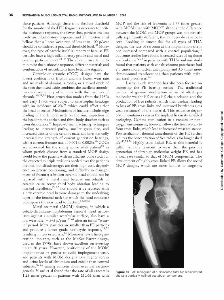
resulting in less osteolysis.65 Moreover, even first-gen-eration implants, such as the McKee-Farrar design,used in the 1970s, have shown excellent survivorshipup to 20 years. However, positioning of the MOMimplant must be precise to avoid impingement wear,and patients with MOM designs have higher serumand urine levels of chromium and cobalt than controlsubjects,66–69 raising concern about eventual carcino-genesis. Visuri et al found that the rate of all cancers is1.23 times greater in patients with MOM than with
MOP and the risk of leukemia is 3.77 times greaterwith MOM than with MOP70; although the differencebetween the MOM and MOP groups was not statisti-cally significantly different, the numbers do raise con-cern. Looking at cancer risk for all types of THAdesigns, the rate of sarcoma at the implantation site isnot increased compared with a control population,71
but some studies have found increased rates of myelomaand leukemia72,73 in patients with THAs and one studyfound that patients with cobalt-chrome prostheses had2.5 times more nuclear aneuploidy and 3.5 times morechromosomal translocations than patients with stain-less steel prostheses.74
Lastly, much attention has also been focused onimproving the PE bearing surface. The traditionalmethod of gamma sterilization in air of ultrahigh-molecular-weight PE causes PE chain scission and theproduction of free radicals, which then oxidize, leadingto loss of PE cross-links and increased brittleness (lesswear resistance) of the material. This oxidative degen-eration continues even as the implant lies in its air-filledpackaging. Gamma sterilization in a vacuum or non-oxygen environment, however, allows the free radicals toform cross-links, which lead to increased wear resistance.Poststerilization thermal annealment of the PE furtherreduces the concentration of free radicals for longer shelflife.40,75,76 Highly cross-linked PE, as this material iscalled, is more resistant to wear than the previousgeneration of ultrahigh-molecular-weight PE and hasa wear rate similar to that of MOM components. Thedevelopment of highly cross-linked PE allows the use ofMOP designs, which are more familiar to surgeons,
Figure 10 AP radiograph of a dislocated total hip replacementshows a vertically inclined acetabular component.
36 SEMINARS IN MUSCULOSKELETAL RADIOLOGY/VOLUME 10, NUMBER 1 2006
Dow
nloa
ded
by: D
artm
outh
Col
lege
. Cop
yrig
hted
mat
eria
l.

more forgiving in their positioning, and more versatilefor making offset liners and constrained liners comparedwith MOM or COC designs.76 However, althoughhighly cross-linked PE is more resistant to wear againstsmooth bearing surfaces, it is not more resistant tothird-body abrasion.77,78
Dislocation
Dislocation is the second most common reason forrevision surgery16,79 and is multifactorial, includingsuch diverse factors as the age and gender of the patient,the surgical approach, size of the components, andposition of the components.79,80 Dislocation within thefirst 3 months after surgery is usually due to laxity of theimmature pseudocapsule of the joint and surroundingsoft tissues. Atraumatic dislocation occurring between3 months and 5 years after surgery is usually due tocomponent malposition, such as an acetabular compo-nent that is either too vertically inclined (more than60 degrees of inclination), too anteverted (opening morethan 20 degrees anteriorly), or retroverted (openingposteriorly). Inclination can be assessed on radiographs,and acetabular version is well assessed on CT scan79,80
(Figs. 10, 11). Dislocation occurring more than 5 yearsafter placement is usually due to gradual stretching of thepseudocapsule and surrounding soft tissue laxity, andwomen are at greater risk than men.79 Surgical optionsfor treating recurrent dislocation include correction ofacetabular malposition, placement of a constrained linerthat provides stability by both deepening the articulatingsocket and limiting the femoral range of motion, andlarger femoral heads.81–84
Infection
Infection is the third most common reason for revisionarthroplasty,16 occurring in 1 to 5% of hip replace-
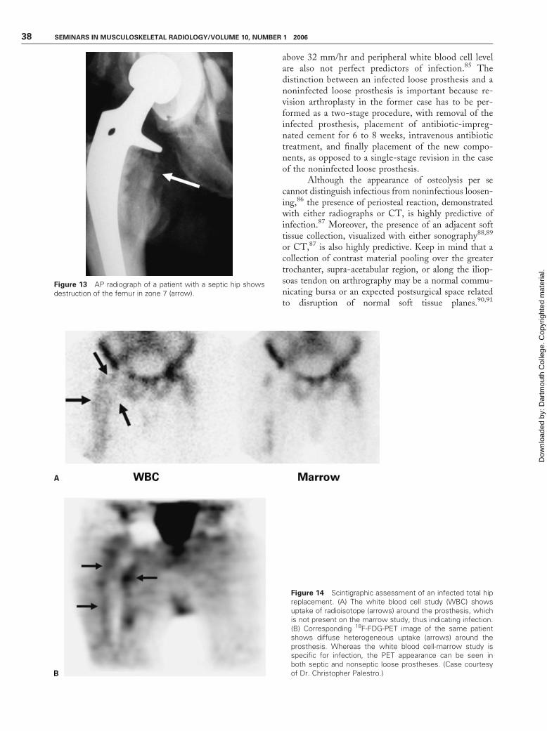
ments.41 Radiographic findings suggestive of infec-tion include a wide irregular radiolucency around thecement-bone interface (in the case of cemented com-ponents) or at the metal-bone interface (in the case ofnoncemented components) and frank bone destruction(Fig. 12, 13).42 However, a distinction between infec-tious osteolysis and aseptic osteolysis related to me-chanical loosening or particle disease often cannot bemade on a single radiograph. Usually, previous radio-graphs are necessary for comparison, with mechanicalloosening and histiocytic response usually taking aslowly progressive course, whereas an acute infectionoccurs with a more rapid time course and more aggres-sive appearance. However, even this feature is notalways reliable because infections can be subclinicaland smoldering, leading to slowly progressive looseningin an afebrile patient. Erythrocyte sedimentation level
Figure 11 CT image through the acetabulumof a patient with recurrent anterior disloca-tions. The angle of acetabular anteversion (A)is measured by drawing a line tangential to theopening of the acetabulum and measuring itcompared with a line in the AP plane of thepatient (short white line). Because the patientmay be lying slightly rotated on the CT table, aline should be drawn tangential to the poste-rior aspects of the posterior columns (longwhite line) to find the correct AP line againstwhich to measure the acetabular version.
Figure 12 AP radiograph of a patient with a painful septic hipshows ill-defined lucency around zone 1 of the acetabular cup(short arrow) and frank perforation of the cup through the medialwall of the acetabulum (long arrow).
IMAGING OF HIP ARTHROPLASTY/MILLER 37
Dow
nloa
ded
by: D
artm
outh
Col
lege
. Cop
yrig
hted
mat
eria
l.
above 32 mm/hr and peripheral white blood cell levelare also not perfect predictors of infection.85 Thedistinction between an infected loose prosthesis and anoninfected loose prosthesis is important because re-vision arthroplasty in the former case has to be per-formed as a two-stage procedure, with removal of theinfected prosthesis, placement of antibiotic-impreg-nated cement for 6 to 8 weeks, intravenous antibiotictreatment, and finally placement of the new compo-nents, as opposed to a single-stage revision in the caseof the noninfected loose prosthesis.
Although the appearance of osteolysis per secannot distinguish infectious from noninfectious loosen-ing,86 the presence of periosteal reaction, demonstratedwith either radiographs or CT, is highly predictive ofinfection.87 Moreover, the presence of an adjacent softtissue collection, visualized with either sonography88,89
or CT,87 is also highly predictive. Keep in mind that acollection of contrast material pooling over the greatertrochanter, supra-acetabular region, or along the iliop-soas tendon on arthrography may be a normal commu-nicating bursa or an expected postsurgical space relatedto disruption of normal soft tissue planes.90,91
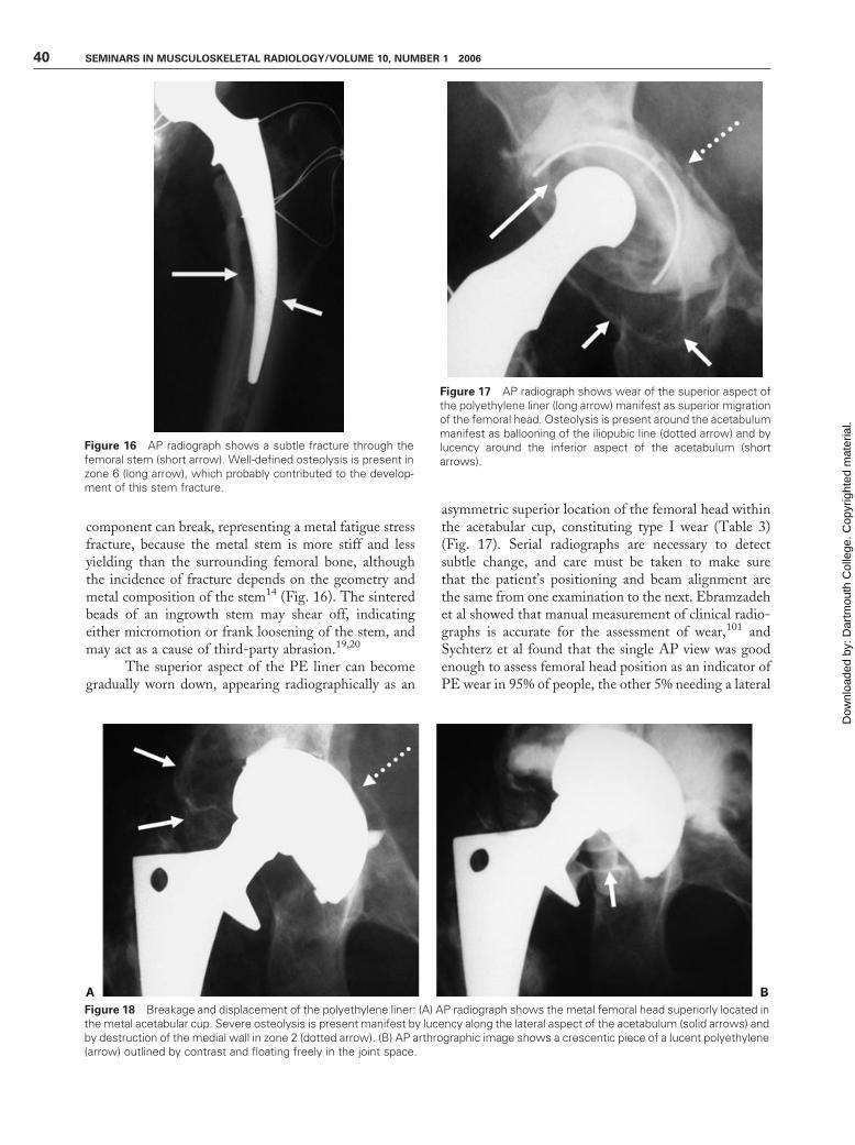
Figure 14 Scintigraphic assessment of an infected total hipreplacement. (A) The white blood cell study (WBC) showsuptake of radioisotope (arrows) around the prosthesis, whichis not present on the marrow study, thus indicating infection.(B) Corresponding 18F-FDG-PET image of the same patientshows diffuse heterogeneous uptake (arrows) around theprosthesis. Whereas the white blood cell-marrow study isspecific for infection, the PET appearance can be seen inboth septic and nonseptic loose prostheses. (Case courtesyof Dr. Christopher Palestro.)
Figure 13 AP radiograph of a patient with a septic hip showsdestruction of the femur in zone 7 (arrow).
38 SEMINARS IN MUSCULOSKELETAL RADIOLOGY/VOLUME 10, NUMBER 1 2006
Dow
nloa
ded
by: D
artm
outh
Col
lege
. Cop
yrig
hted
mat
eria
l.

A communicating nonbursal cavity with an irregular,nonsmooth lining is more likely to be infected.91,92
The gold standard for the evaluation of a clinicallysuspected infected joint is aspiration, with Gram stainand culture and sensitivity of joint fluid. Although it isconsidered the definitive diagnostic test, its reportedsensitivity is quite variable, ranging from 28% to92%.85,93 Some of the reported variability may be dueto the cohorts of patients that have been studied, andmore accurate results are obtained if aspiration is re-served for cases with high clinical suspicion of infectionor periosteal reaction.94
Various scintigraphic methods are also availablefor evaluation. Three-phase bone scan can be used butsuffers from poor specificity because a cemented femoralcomponent can show increased uptake around the pros-thesis for several years after placement and because anormal noncemented prosthesis also shows increasedradiotracer uptake related to the normal bony ingrowththat occurs around the prosthesis. Moreover, new areasof radiotracer uptake compared with prior scans can becaused by both infectious and noninfectious loosening.However, as a normal bone scan is reliable for excludingloosening, it can be used as an initial screening test.Adding a gallium scan to the standard technetium bonescan can improve the diagnostic accuracy for infection to70 to 80%: infection is excluded if the gallium scan isnormal or has less intense uptake than the correspondingbone scan, and infection is diagnosed when there isuptake of gallium without corresponding Tc uptake orthe gallium uptake is more intense than correspondingTc uptake.95
The combination of technetium- or indium-labeled white cells and technetium-labeled sulfur colloidhas excellent results, with accuracy of over 90%, and iscurrently the scintigraphic method of choice for evaluat-ing suspected infection.95,96 The imaging feature ofinfection is spatial incongruence, in which there isuptake of the labeled white cells (regardless of intensity)without uptake of the sulfur colloid (Fig. 14).
Fluorodeoxyglucose–positron emission tomog-raphy (FDG-PET) scanning has variable performance.Chacko et al reported 92% sensitivity and 97% specif-icity.97 Stumpe et al reported sensitivity of only 22 to33%, with an overall accuracy of 69%, which was thesame as that of radiographs and worse than that ofthree-phase bone scan.98 Similarly, Love et al, usingfour different combinations of uptake criteria, had anaccuracy of only 43 to 78%.96 Normal persistent post-surgical uptake in the soft tissues around the prosthetichead and neck is a potential pitfall in interpretation,97
and aseptic loosening related to particle disease can alsocause increased FDG uptake and thus false-positivescans.96,98 (Fig. 14) Chacko et al advised that thelocation of the uptake is more important than theintensity of the uptake.97
Periprosthetic Fracture
Periprosthetic fractures are rare and occur more oftenaround the femoral than the acetabular component.Fracture of the femur may occur during placement ofthe femoral stem, usually as either focal cortical pene-tration or longitudinal splitting of the bone, and happensmore often with uncemented components than ce-mented ones (5% versus 0.3%) because of the tight pressfit needed with uncemented stems.99 The incidence iseven higher in revision THA, with an incidence of 6.3%for cemented THAs and almost 18 % in noncementedcases.100 In addition, intraoperative periprosthetic femurfractures occur more often during revision arthroplasty(7.8%) than primary arthroplasty (1%) because of poorbone stock resulting from osteoporosis or prior osteol-ysis.99 In the case of longitudinal splitting, a long stem(to bypass the fracture) and circumferential bandingwires are usually used to correct the problem. Fractureof the femur may also occur any time after hip replace-ment, typically at the level of the tip of the femoral stembecause of ‘‘stress risers’’ at this level caused by thedifference in stiffness between the metal stem andbony shaft (Fig. 15). These fractures are also morecommon in revision hips (4%) than primary arthroplas-ties (1.1%) because of deficient bone stock.99
Hardware Failure
Hardware failure can affect both the femoral andacetabular components. The stem of the femoral
Figure 15 AP radiograph shows a fracture of the femur at thetip of the femoral stem with overriding of the fracture fragments.Irregular lucency is also present around the cement-bone inter-face at the distal aspect of the stem, which probably contributedto the stress riser effect.
IMAGING OF HIP ARTHROPLASTY/MILLER 39
Dow
nloa
ded
by: D
artm
outh
Col
lege
. Cop
yrig
hted
mat
eria
l.
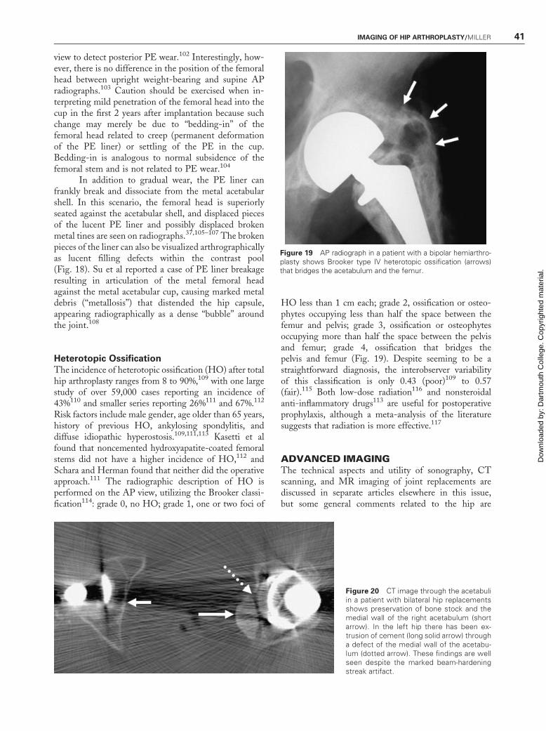
component can break, representing a metal fatigue stressfracture, because the metal stem is more stiff and lessyielding than the surrounding femoral bone, althoughthe incidence of fracture depends on the geometry andmetal composition of the stem14 (Fig. 16). The sinteredbeads of an ingrowth stem may shear off, indicatingeither micromotion or frank loosening of the stem, andmay act as a cause of third-party abrasion.19,20
The superior aspect of the PE liner can becomegradually worn down, appearing radiographically as an
asymmetric superior location of the femoral head withinthe acetabular cup, constituting type I wear (Table 3)(Fig. 17). Serial radiographs are necessary to detectsubtle change, and care must be taken to make surethat the patient’s positioning and beam alignment arethe same from one examination to the next. Ebramzadehet al showed that manual measurement of clinical radio-graphs is accurate for the assessment of wear,101 andSychterz et al found that the single AP view was goodenough to assess femoral head position as an indicator ofPE wear in 95% of people, the other 5% needing a lateral
Figure 17 AP radiograph shows wear of the superior aspect ofthe polyethylene liner (long arrow) manifest as superior migrationof the femoral head. Osteolysis is present around the acetabulummanifest as ballooning of the iliopubic line (dotted arrow) and bylucency around the inferior aspect of the acetabulum (shortarrows).
Figure 18 Breakage and displacement of the polyethylene liner: (A) AP radiograph shows the metal femoral head superiorly located inthe metal acetabular cup. Severe osteolysis is present manifest by lucency along the lateral aspect of the acetabulum (solid arrows) andby destruction of the medial wall in zone 2 (dotted arrow). (B) AP arthrographic image shows a crescentic piece of a lucent polyethylene(arrow) outlined by contrast and floating freely in the joint space.
Figure 16 AP radiograph shows a subtle fracture through thefemoral stem (short arrow). Well-defined osteolysis is present inzone 6 (long arrow), which probably contributed to the develop-ment of this stem fracture.
40 SEMINARS IN MUSCULOSKELETAL RADIOLOGY/VOLUME 10, NUMBER 1 2006
Dow
nloa
ded
by: D
artm
outh
Col
lege
. Cop
yrig
hted
mat
eria
l.
view to detect posterior PE wear.102 Interestingly, how-ever, there is no difference in the position of the femoralhead between upright weight-bearing and supine APradiographs.103 Caution should be exercised when in-terpreting mild penetration of the femoral head into thecup in the first 2 years after implantation because suchchange may merely be due to ‘‘bedding-in’’ of thefemoral head related to creep (permanent deformationof the PE liner) or settling of the PE in the cup.Bedding-in is analogous to normal subsidence of thefemoral stem and is not related to PE wear.104
In addition to gradual wear, the PE liner canfrankly break and dissociate from the metal acetabularshell. In this scenario, the femoral head is superiorlyseated against the acetabular shell, and displaced piecesof the lucent PE liner and possibly displaced brokenmetal tines are seen on radiographs.37,105–107 The brokenpieces of the liner can also be visualized arthrographicallyas lucent filling defects within the contrast pool(Fig. 18). Su et al reported a case of PE liner breakageresulting in articulation of the metal femoral headagainst the metal acetabular cup, causing marked metaldebris (‘‘metallosis’’) that distended the hip capsule,appearing radiographically as a dense ‘‘bubble’’ aroundthe joint.108
Heterotopic Ossification
The incidence of heterotopic ossification (HO) after totalhip arthroplasty ranges from 8 to 90%,109 with one largestudy of over 59,000 cases reporting an incidence of43%110 and smaller series reporting 26%111 and 67%.112
Risk factors include male gender, age older than 65 years,history of previous HO, ankylosing spondylitis, anddiffuse idiopathic hyperostosis.109,111,113 Kasetti et alfound that noncemented hydroxyapatite-coated femoralstems did not have a higher incidence of HO,112 andSchara and Herman found that neither did the operativeapproach.111 The radiographic description of HO isperformed on the AP view, utilizing the Brooker classi-fication114: grade 0, no HO; grade 1, one or two foci of
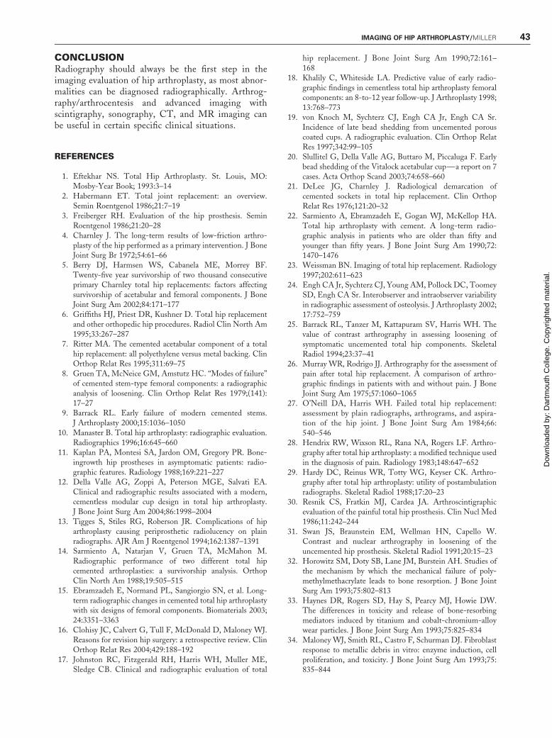
HO less than 1 cm each; grade 2, ossification or osteo-phytes occupying less than half the space between thefemur and pelvis; grade 3, ossification or osteophytesoccupying more than half the space between the pelvisand femur; grade 4, ossification that bridges thepelvis and femur (Fig. 19). Despite seeming to be astraightforward diagnosis, the interobserver variabilityof this classification is only 0.43 (poor)109 to 0.57(fair).115 Both low-dose radiation116 and nonsteroidalanti-inflammatory drugs113 are useful for postoperativeprophylaxis, although a meta-analysis of the literaturesuggests that radiation is more effective.117
ADVANCED IMAGINGThe technical aspects and utility of sonography, CTscanning, and MR imaging of joint replacements arediscussed in separate articles elsewhere in this issue,but some general comments related to the hip are
Figure 19 AP radiograph in a patient with a bipolar hemiarthro-plasty shows Brooker type IV heterotopic ossification (arrows)that bridges the acetabulum and the femur.
Figure 20 CT image through the acetabuliin a patient with bilateral hip replacementsshows preservation of bone stock and themedial wall of the right acetabulum (shortarrow). In the left hip there has been ex-trusion of cement (long solid arrow) througha defect of the medial wall of the acetabu-lum (dotted arrow). These findings are wellseen despite the marked beam-hardeningstreak artifact.
IMAGING OF HIP ARTHROPLASTY/MILLER 41
Dow
nloa
ded
by: D
artm
outh
Col
lege
. Cop
yrig
hted
mat
eria
l.

appropriate here. Sonography can be used to evaluatethe presence of joint effusion or periarticular fluidcollections associated with an infected prosthesis. Ithas been suggested that a joint effusion that distendsthe joint pseudocapsule more than 3.2 mm away fromthe proximal femoral shaft strongly suggests the presenceof acute infection,89 but other studies have questionedthis.90
CT and MR imaging are limited by beam-hardening artifact and dephasing artifact, respectively,caused by the metal components, but multidetector CTscanning with overlapping slices and MR imaging usingmetal artifact reduction techniques allow these modal-ities to be used in the evaluation of the painful hiparthroplasty. CT is more sensitive than radiographs forevaluation of lysis of the medial wall of the acetabu-lum,118–120 and it can be helpful for evaluating theamount of surrounding femoral and acetabular bonestock in preparation for revision surgery24,121 (Fig. 20).Cup and femoral neck version can also be measured fromeither standard two-dimensional (2D) axial im-ages122,123 or 3D models.124
MR imaging, specifically tailored to reduce metalartifact, can depict the periprosthetic tissue on bothhigh-field-strength125,126 and low-field-strength mag-nets127 (Fig. 21). The appearance of periprosthetic softtissue masses related to histiocytic osteolysis is variable;Potter et al described intermediate signal intensity col-lections with low-signal-intensity rims on T2-weightedimages,126 and White et al described low-signal-inten-sity collections on T1-weighted sequences that wereheterogeneously low to intermediate signal intensity onT2-weighted images.125 Infected collections have a sig-nal intensity more similar to that of fluid,126 with
contrast-enhancing rims125 (Fig. 22). Other causes ofpain after THA detected with MR imaging includeavulsion of the abductor muscles from the greater tro-chanter128 and fracture of the femoral stem.129 Using a0.5 T magnet to evaluate the femoral stem, Sugimotoet al reported that high signal intensity surrounding thestem on short inversion time inversion recovery (STIR)images, either with or without contrast enhancement,indicated loosening or a histiocytic response, and lowsignal intensity correlated with a normal radiographicappearance and a stable stem.127
Figure 22 Periprosthetic abscess using a 1.5T scanner: (A) Axial fat-suppressed T2-weighted image through the thigh at the level ofthe prosthetic femoral stem shows signal void due to the stem (short arrow) with surrounding dephasing artifact, but the high-signal-intensity abscess in the lateral soft tissues is well seen (long arrow). (B) Corresponding axial fat-suppressed T1-weighted image afterthe intravenous administration of gadolinium contrast material shows the low-signal-intensity abscess with the brightly enhancingrim (long arrow). The signal void from the prosthetic stem (arrow) and surrounding dephasing artifact does not affect the appearanceof the abscess.
Figure 21 Axial proton density image on a 1.5T scanner throughthe acetabulum of a patient with a total hip replacement showsdephasing artifact around the acetabular cup itself but the sur-rounding bone and medial wall of the acetabulum (arrow) are stillwell visualized.
42 SEMINARS IN MUSCULOSKELETAL RADIOLOGY/VOLUME 10, NUMBER 1 2006
Dow
nloa
ded
by: D
artm
outh
Col
lege
. Cop
yrig
hted
mat
eria
l.
CONCLUSIONRadiography should always be the first step in theimaging evaluation of hip arthroplasty, as most abnor-malities can be diagnosed radiographically. Arthrog-raphy/arthrocentesis and advanced imaging withscintigraphy, sonography, CT, and MR imaging canbe useful in certain specific clinical situations.
REFERENCES
1. Eftekhar NS. Total Hip Arthroplasty. St. Louis, MO:Mosby-Year Book; 1993:3–14
2. Habermann ET. Total joint replacement: an overview.Semin Roentgenol 1986;21:7–19
3. Freiberger RH. Evaluation of the hip prosthesis. SeminRoentgenol 1986;21:20–28
4. Charnley J. The long-term results of low-friction arthro-plasty of the hip performed as a primary intervention. J BoneJoint Surg Br 1972;54:61–66
5. Berry DJ, Harmsen WS, Cabanela ME, Morrey BF.Twenty-five year survivorship of two thousand consecutiveprimary Charnley total hip replacements: factors affectingsurvivorship of acetabular and femoral components. J BoneJoint Surg Am 2002;84:171–177
6. Griffiths HJ, Priest DR, Kushner D. Total hip replacementand other orthopedic hip procedures. Radiol Clin North Am1995;33:267–287
7. Ritter MA. The cemented acetabular component of a totalhip replacement: all polyethylene versus metal backing. ClinOrthop Relat Res 1995;311:69–75
8. Gruen TA, McNeice GM, Amstutz HC. ‘‘Modes of failure’’of cemented stem-type femoral components: a radiographicanalysis of loosening. Clin Orthop Relat Res 1979;(141):17–27
9. Barrack RL. Early failure of modern cemented stems.J Arthroplasty 2000;15:1036–1050
10. Manaster B. Total hip arthroplasty: radiographic evaluation.Radiographics 1996;16:645–660
11. Kaplan PA, Montesi SA, Jardon OM, Gregory PR. Bone-ingrowth hip prostheses in asymptomatic patients: radio-graphic features. Radiology 1988;169:221–227
12. Della Valle AG, Zoppi A, Peterson MGE, Salvati EA.Clinical and radiographic results associated with a modern,cementless modular cup design in total hip arthroplasty.J Bone Joint Surg Am 2004;86:1998–2004
13. Tigges S, Stiles RG, Roberson JR. Complications of hiparthroplasty causing periprosthetic radiolucency on plainradiographs. AJR Am J Roentgenol 1994;162:1387–1391
14. Sarmiento A, Natarjan V, Gruen TA, McMahon M.Radiographic performance of two different total hipcemented arthroplasties: a survivorship analysis. OrthopClin North Am 1988;19:505–515
15. Ebramzadeh E, Normand PL, Sangiorgio SN, et al. Long-term radiographic changes in cemented total hip arthroplastywith six designs of femoral components. Biomaterials 2003;24:3351–3363
16. Clohisy JC, Calvert G, Tull F, McDonald D, Maloney WJ.Reasons for revision hip surgery: a retrospective review. ClinOrthop Relat Res 2004;429:188–192
17. Johnston RC, Fitzgerald RH, Harris WH, Muller ME,Sledge CB. Clinical and radiographic evaluation of total
hip replacement. J Bone Joint Surg Am 1990;72:161–168
18. Khalily C, Whiteside LA. Predictive value of early radio-graphic findings in cementless total hip arthroplasty femoralcomponents: an 8-to-12 year follow-up. J Arthroplasty 1998;13:768–773
19. von Knoch M, Sychterz CJ, Engh CA Jr, Engh CA Sr.Incidence of late bead shedding from uncemented porouscoated cups. A radiographic evaluation. Clin Orthop RelatRes 1997;342:99–105
20. Slullitel G, Della Valle AG, Buttaro M, Piccaluga F. Earlybead shedding of the Vitalock acetabular cup—a report on 7cases. Acta Orthop Scand 2003;74:658–660
21. DeLee JG, Charnley J. Radiological demarcation ofcemented sockets in total hip replacement. Clin OrthopRelat Res 1976;121:20–32
22. Sarmiento A, Ebramzadeh E, Gogan WJ, McKellop HA.Total hip arthroplasty with cement. A long-term radio-graphic analysis in patients who are older than fifty andyounger than fifty years. J Bone Joint Surg Am 1990;72:1470–1476
23. Weissman BN. Imaging of total hip replacement. Radiology1997;202:611–623
24. Engh CA Jr, Sychterz CJ, Young AM, Pollock DC, ToomeySD, Engh CA Sr. Interobserver and intraobserver variabilityin radiographic assessment of osteolysis. J Arthroplasty 2002;17:752–759
25. Barrack RL, Tanzer M, Kattapuram SV, Harris WH. Thevalue of contrast arthrography in assessing loosening ofsymptomatic uncemented total hip components. SkeletalRadiol 1994;23:37–41
26. Murray WR, Rodrigo JJ. Arthrography for the assessment ofpain after total hip replacement. A comparison of arthro-graphic findings in patients with and without pain. J BoneJoint Surg Am 1975;57:1060–1065
27. O’Neill DA, Harris WH. Failed total hip replacement:assessment by plain radiographs, arthrograms, and aspira-tion of the hip joint. J Bone Joint Surg Am 1984;66:540–546
28. Hendrix RW, Wixson RL, Rana NA, Rogers LF. Arthro-graphy after total hip arthroplasty: a modified technique usedin the diagnosis of pain. Radiology 1983;148:647–652
29. Hardy DC, Reinus WR, Totty WG, Keyser CK. Arthro-graphy after total hip arthroplasty: utility of postambulationradiographs. Skeletal Radiol 1988;17:20–23
30. Resnik CS, Fratkin MJ, Cardea JA. Arthroscintigraphicevaluation of the painful total hip prosthesis. Clin Nucl Med1986;11:242–244
31. Swan JS, Braunstein EM, Wellman HN, Capello W.Contrast and nuclear arthrography in loosening of theuncemented hip prosthesis. Skeletal Radiol 1991;20:15–23
32. Horowitz SM, Doty SB, Lane JM, Burstein AH. Studies ofthe mechanism by which the mechanical failure of poly-methylmethacrylate leads to bone resorption. J Bone JointSurg Am 1993;75:802–813
33. Haynes DR, Rogers SD, Hay S, Pearcy MJ, Howie DW.The differences in toxicity and release of bone-resorbingmediators induced by titanium and cobalt-chromium-alloywear particles. J Bone Joint Surg Am 1993;75:825–834
34. Maloney WJ, Smith RL, Castro F, Schurman DJ. Fibroblastresponse to metallic debris in vitro: enzyme induction, cellproliferation, and toxicity. J Bone Joint Surg Am 1993;75:835–844
IMAGING OF HIP ARTHROPLASTY/MILLER 43
Dow
nloa
ded
by: D
artm
outh
Col
lege
. Cop
yrig
hted
mat
eria
l.
35. Santavirta S, Hoikka V, Eskola A, Konttinen YT, Paavilai-nen T, Tallroth K. Aggressive granulomatous lesions incementless total hip arthroplasty. J Bone Joint Surg Br 1990;72:980–983
36. Konttinen YT, Zhao D, Beklen A, et al. The microenviron-ment around total hip replacement prostheses. Clin OrthopRelat Res 2005;430:28–38
37. Della Valle AG, Ruzo PS, Li S, Pellicci P, Sculco TP, SalvatiEA. Dislodgment of polyethylene liners in first and secondgeneration Harris-Galante acetabular components: a reportof eighteen cases. J Bone Joint Surg Am 2001;83:553–559
38. Huk OL, Bansal M, Betts F, et al. Polyethylene and metaldebris generated by non-articulating surfaces of modularacetabular components. J Bone Joint Surg Br 1994;76:568–574
39. Morscher EW, Hefti A, Aebi U. Severe osteolysis afterthird-body wear due to hydroxyapatite particles fromacetabular cup coating. J Bone Joint Surg Br 1998;80:267–272
40. McKellop HA. Bearing surfaces in total hip replacements:state of the art and future developments. Instr Course Lect2001;50:165–179
41. Bauer TW, Schils J. The pathology of total joint arthroplastyII: mechanisms of implant failure. Skeletal Radiol 1999;28:483–497
42. Keogh C, Munk PL, Gee R, Chan LP, Marchinkow LO.Imaging of the painful hip arthroplasty. AJR Am JRoentgenol 2003;180:115–120
43. Schmalzried TP, Jasty M, Harris WH. Periprosthetic boneloss in total hip arthroplasty. J Bone Joint Surg Am 1992;74:849–863
44. Campbell DG, Garvuz DS, Masri BA, Duncan CP.Reliability of acetabular bone defect classification systems inrevision total hip arthroplasty. J Arthroplasty 2001;16:83–86
45. Zimlich RH, Fehring TK. Underestimation of pelvicosteolysis: the value of the iliac oblique radiograph. JArthroplasty 2000;15:796–801
46. Southwell DG, Bechtold JE, Lew WD, Schmidt AH.Improving the detection of acetabular osteolysis usingoblique radiographs. J Bone Joint Surg Br 1999;8:289–295
47. Claus AM, Engh CA Jr, Sychterz CJ, Xenos JS, OrishimoKF, Engh CA Sr. Radiographic definition of pelvic osteolysisfollowing total hip arthroplasty. J Bone Joint Surg Am2003;85:1519–1526
48. Walde TA, Mohan V, Leung S, Engh CA Sr. Sensitivityand specificity of plain radiographs for detection of medial-wall perforation secondary to osteolysis. J Arthroplasty 2005;20:20–24
49. Claus AM, Totterman SM, Sychterz CJ, Tamez-Pena JG,Looney RJ, Engh CA Sr. Computed tomography to assesspelvic lysis after total hip replacement. Clin Orthop RelatRes 2004;422:167–174
50. Dumbleton JH,Manley MT, Edidin AA. A literature reviewof the association between wear rate and osteolysis in totalhip arthroplasty. J Arthroplasty 2002;17:649–661
51. Silva M, Heisel C, Schmalzried TP. Metal-on-metal totalhip replacement. Clin Orthop Relat Res 2005;430:53–61
52. Doorn PF, Campbell PA, Worrall J, Benya PD, McKellopHA, Amstutz HC.Metal wear particle characterization frommetal on metal total hip replacements: transmission electronmicroscopy study of periprosthetic tissues and isolatedparticles. J Biomed Mater Res 1998;42:103–111
53. Hannouche D, Hamadouche M, Nizard R, Bizot P,Meunier A, Sedel L. Ceramics in total hip replacement.Clin Orthop Relat Res 2005;430:62–71
54. Bos I, Willmann G. Morphologic characteristics of peri-prosthetic tissues from hip prostheses with ceramic-ceramiccouples. Acta Orthop Scand 2001;72:335–342
55. De Aza AH, Chevalier J, Fantozzi F, Schehl M, TorrecillasR. Crack growth resistance of alumina, zirconia and zirconiatoughened alumina ceramics for joint prostheses. Biomater-ials 2002;23:937–945
56. Callaway GH, Flynn W, Ranawat CS, Sculco TP. Fractureof the femoral head after ceramic-on-polyethylene total hiparthroplasty. J Arthroplasty 1995;10:855–859
57. Kim YH, Ritchie A, Hardaker C. Surface roughness ofceramic femoral heads after in vivo transfer of metal:correlation to polyethylene wear. J Bone Joint Surg Am2005;87:577–582
58. Yoo JJ, Kim YM, Yoon KS, Koo KH, Song WS, Kim HG.Alumina-on-alumina total hip arthroplasty: a five yearfollow-up study. J Bone Joint Surg Am 2005;87:530–535
59. Allain J, Roudot-Thorval F, Delecrin J, Anract P, MigaudH, Goutallier D. Revision total hip arthroplasty performedafter fracture of a ceramic femoral head: a multicentersurvivorship study. J Bone Joint Surg Am 2003;85:825–830
60. Matziolis G, Perka C, Disch A. Massive metallosis afterrevision of a fractured ceramic head onto a metal head. ArchOrthop Trauma Surg 2003;123:48–50
61. Matsuda Y, Yamamuro T. Metallosis due to abnormalabrasion of the femoral head in bipolar hip prosthesis.Implant retrieval and analysis in six cases. Med Prog Technol1994;20:185–189
62. Kempf I, Semlitsch M. Massive wear of a steel ball head byceramic fragments in the polyethylene acetabular cup afterrevision of a total hip prosthesis with fractured ceramic ball.Arch Orthop Trauma Surg 1990;109:284–287
63. Masonis JL, Bourne RB, Ries MD, McCalden RW, SalehiA, Kelman DC. Zirconia femoral head fractures: a clinicaland retrieval analysis. J Arthroplasty 2004;19:898–905
64. Muller ME. The benefits of metal-on-metal total hipreplacements. Clin Orthop Relat Res 1995;311:54–59
65. Dorr LD, Wan Z, Longjohn DB, Dubois B, Murken R.Total hip arthroplasty with use of the Metasul metal-on-metal articulation. J Bone Joint Surg Am 2000;82:789–798
66. Jacobs JJ, Skipor AK, Doorn PF, et al. Cobalt and chromiumconcentrations in patients with metal on metal total hipreplacements. Clin Orthop Relat Res 1996;329(Suppl):S256–S263
67. Lhotka C, Szekeres T, Steffan I, Zhuber K, Zweymuller K.Four-year study of cobalt and chromium blood levels inpatients managed with two different metal-on-metal totalhip replacements. J Orthop Res 2003;21:189–195
68. Schaffer AW, Pilger A, Engelhardt C, Zweymuller K,Ruediger HW. Increased blood cobalt and chromium aftertotal hip replacement. J Toxicol Clin Toxicol 1999;37:839–844
69. Maezawa K, Nozawa M, Hirose T, et al. Cobalt andchromium concentrations in patients with metal-on-metaland other cementless total hip arthroplasty. Arch OrthopTrauma Surg 2002;122:283–287
70. Visuri T, Pukkala E, Paavolainen P, Pulkkinen P, Riska EB.Cancer risk after metal on metal and polyethylene on metal
44 SEMINARS IN MUSCULOSKELETAL RADIOLOGY/VOLUME 10, NUMBER 1 2006
Dow
nloa
ded
by: D
artm
outh
Col
lege
. Cop
yrig
hted
mat
eria
l.
total hip arthroplasty. Clin Orthop Relat Res 1996;329(Suppl):S280–S289
71. Tharani R, Dorey FJ, Schmalzried TP. The risk of cancerfollowing total hip or knee arthroplasty. J Bone Joint SurgAm 2001;83:774–780
72. Paavolainen P, Pukkala E, Pulkkinen P, Visuri T. Cancerincidence in Finnish hip replacement patients from 1980 to1995: a nationwide cohort study involving 31,651 patients.J Arthroplasty 1999;14:272–280
73. Signorello LB, Ye W, Fryzek JP, et al. Nationwide study ofcancer risk among hip replacement patients in Sweden. J NatlCancer Inst 2001;93:1405–1410
74. Doherty AT, Howell RT, Ellis LA, et al. Increasedchromosome translocations and aneuploidy in peripheralblood lymphocytes of patients having revision arthroplasty ofthe hip. J Bone Joint Surg Br 2001;83:1075–1081
75. Santavirta S, Bohler M, Harris WH, et al. Alternativematerials to improve total hip replacement tribology. ActaOrthop Scand 2003;74:380–388
76. Harris WH, Muratoglu OK. A review of current cross-linked polyethylenes used in total hip arthroplasty. ClinOrthop Relat Res 2005;430:46–52
77. Sakoda H, Voice AM, McEwen HM, et al. A comparison ofthe wear and physical properties of silane cross-linkedpolyethylene and ultra-high molecular weight polyethylene.J Arthroplasty 2001;16:1018–1023
78. Shen FW, McKellop H. Surface-gradient cross-linkedpolyethylene acetabular cups: oxidation resistance and wearagainst smooth and rough femoral balls. Clin Orthop RelatRes 2005;430:80–88
79. Hamilton WG, McCauley JP. Evaluation of the unstabletotal hip arthroplasty. Instr Course Lect 2004;53:87–92
80. Soong M, Eubash HE, Macaulay W. Dislocation after totalhip arthroplasty. J Am Acad Orthop Surg 2004;12:314–321
81. Shrader MW, Parvizi J, Lewallen DG. The use of a con-strained acetabular component to treat instability after totalhip arthroplasty. J Bone Joint Surg Am 2003;85:2179–2183
82. Amstutz HC, Le Duff MJ, Beaule PE. Prevention andtreatment of dislocation after total hip replacement usinglarge diameter balls. Clin Orthop Relat Res 2004;429:108–116
83. Padgett DE, Warashina H. The unstable total hip replace-ment. Clin Orthop Relat Res 2004;420:72–79
84. Lachiewicz PF, Kelley SS. The use of constrained compo-nents in total hip arthroplasty. J Am Acad Orthop Surg2002;10:233–238
85. Lachiewicz PF, Rogers GD, Thomason HC. Aspiration ofthe hip joint before revision total hip arthroplasty. Clinicaland laboratory factors influencing attainment of a positiveculture. J Bone Joint Surg Am 1996;78:749–754
86. Tigges S, Stiles RG, Roberson JR. Appearance of septic hipprostheses on plain radiographs. AJR Am J Roentgenol1994;163:377–380
87. Cyteval C, Hamm V, Sarrabere MP, Lopez FM, Maury P,Taourel P. Painful infection at the site of hip prosthesis: CTimaging. Radiology 2002;224:477–483
88. van Holsbeeck MT, Eyler WR, Sherman LS, et al.Detection of infection in loosened hip prostheses: efficacyof sonography. AJR Am J Roentgenol 1994;163:381–384
89. Weybright PN, Jacobson JA, Murry KH, et al. Limitedeffectiveness of sonography in revealing hip joint effusion:preliminary results in 21 adult patients with native and
postoperative hips. AJR Am J Roentgenol 2003;181:215–218
90. Steinbach LS, Schneider R, Goldman AB, Kazam E,Ranawat CS, Ghelman B. Bursae and abscess cavitiescommunicating with the hip. Diagnosis using arthrographyand CT. Radiology 1985;156:303–307
91. Berquist TH, Bender CE, Maus TP, Ward EM, Rand JA.Pseudobursae: a useful finding in patients with painful hiparthroplasty. AJR Am J Roentgenol 1987;148:103–106
92. Maus TP, Berquist TH, Bender CE, Rand JA. Arthro-graphic study of painful total hip arthroplasty: refinedcriteria. Radiology 1987;162:721–727
93. Teller RE, Christie MJ, Martin W, Nance EP, Haas DW.Sequential indium-labeled leukocyte and bone scans todiagnose prosthetic joint infection. Clin Orthop Relat Res2000;373:241–247
94. Barrack RL, Harris WH. The value of aspiration of the hipjoint before revision total hip arthroplasty. J Bone Joint SurgAm 1993;75:66–76
95. Love C, Tomas MB, Marwin SE, Pugliese PV, Palestro CJ.Role of nuclear medicine in diagnosis of the infected jointreplacement. Radiographics 2001;21:1229–1238
96. Love C, Marwin SE, TomasMB, et al. Diagnosing infectionin the failed joint replacement: a comparison of coincidencedetection 18F-FDG and 111In-labeled leukocyte/99mTc-sulfur colloid marrow imaging. J Nucl Med 2004;45:1864–1871
97. Chacko TK, Zhuang H, Stevenson K, Moussavian B, AlaviA. The importance of the location of fluorodeoxyglucoseuptake in periprosthetic infection in painful hip prostheses.Nucl Med Commun 2002;23:851–855
98. Stumpe K, Notzli HP, Zannetti M, et al. FDG PET fordifferentiation of infection and aseptic loosening in total hipreplacements: comparison with conventional radiography andthree-phase bone scintigraphy. Radiology 2004;231:333–341
99. Berry DJ. Epidemiology: hip and knee. Orthop Clin NorthAm 1999;30:183–190
100. Tsiridis E, Haddad FS, Gie GA. The management ofperiprosthetic femoral fractures around hip replacements.Injury 2003;34:95–105
101. Ebramzadeh E, Sangiorgio SN, Lattuada F, et al. Accuracyof measurements of polyethylene wear with use of radio-graphs of total hip replacements. J Bone Joint Surg Am2003;85:2378–2384
102. Sychterz CJ, Yang AM, McAuley JP, Engh CA. Two-dimensional versus three-dimensional radiographic measure-ments of polyethylene wear. Clin Orthop Relat Res 1999;365:117–123
103. Moore KD, Barrack RL, Sychterz CJ, Sawhney J, Yang AM,Engh CA. The effect of weight-bearing on the radiographicmeasurement of the position of the femoral head after totalhip arthroplasty. J Bone Joint Surg Am 2000;82:62–69
104. Sychterz CJ, Engh CA Jr, Yang A, Engh CA. Analysis oftemporal wear patterns of porous-coated acetabular compo-nents: distinguishing between true wear and so-calledbedding-in. J Bone Joint Surg Am 1999;81:821–830
105. Werle J, Goodman S, Schurman D, Lannin J. Polyethyleneliner dissociation in Harris-Galante acetabular components.J Arthroplasty 2002;17:78–81
106. Han CD, Choe WS, Yoo JH. Late dissociation of thepolyethylene liner from a modular acetabular metal shell afterprimary total hip-arthroplasty: a report of five cases. YonseiMed J 1998;39:277–282
IMAGING OF HIP ARTHROPLASTY/MILLER 45
Dow
nloa
ded
by: D
artm
outh
Col
lege
. Cop
yrig
hted
mat
eria
l.
107. Mihalko WM, Papdemetriou T. Polyethylene liner dissocia-tion with the Harris-Galante II acetabular component. ClinOrthop Relat Res 2001;386:166–172
108. Su EP, Callander PW, Salvati EA. The bubble sign: a newradiographic sign in total hip arthroplasty. J Arthroplasty2003;18:110–112
109. Della Valle AG, Ruzo PS, Pavone V, Tolo E, Mintz DN,Salvati EA. Heterotopic ossification after total hip arthro-plasty. J Arthroplasty 2002;17:870–875
110. Neal B, Gray H, McMahon S, Dunn L. Incidence ofheterotopic bone formation after major hip surgery. ANZ JSurg 2002;72:808–821
111. Schara K, Herman S. Heterotopic bone formation in totalhip arthroplasty: predisposing factors, classification and thesignificance for clinical outcome. Acta Chir OrthopTraumatol Cech 2001;68:105–108
112. Kasetti RJ, Shetty AA, Rand C. Heterotopic ossificationafter uncemented hydroxyapatite-coated primary total hiparthroplasty. J Arthroplasty 2001;16:1038–1042
113. Fransen M, Neal B. Non-steroidal anti-inflammatory drugsfor preventing heterotopic bone formation after hip arthro-plasty. Cochrane Database Syst Rev 2004:CD 001160
114. Brooker AF, Bowerman JW, Robinson RA, Riley LH Jr.Ectopic ossification following total hip replacement. Inci-dence and a method of classification. J Bone Joint Surg Am1973;56:1629–1632
115. Wright JG, Moran E, Bogoch E. Reliability and validity ofthe grading of heterotopic ossification. J Arthroplasty 1994;9:549–553
116. Padgett DE, Holley KG, CummingsM, et al. The efficacy of500 centigray radiation in the prevention of heterotopicossification after total hip arthroplasty: a prospective,randomized, pilot study. J Arthroplasty 2003;18:677–686
117. Pakos EE, Ioannidis JP. Radiotherapy vs. nonsteroidal anti-inflammatory drugs for the prevention of heterotopicossification after hip procedures: a meta-analysis of rando-mized trials. Int J Radiat Oncol Biol Phys 2004;60:888–895
118. Robertson DD, Sutherland CJ, Lopes T, Yuan J. Preopera-tive description of severe acetabular defects caused by failedtotal hip replacement. J Comput Assist Tomogr 1998;22:444–449
119. Puri L, Wixson RL, Stern SH, Kohli J, Hendriz RW,Stulberg SD. Use of helical computed tomography for theassessment of acetabular osteolysis after total hip arthro-plasty. J Bone Joint Surg Am 2002;84:609–614
120. Leung S, Naudie D, Kitamura N, Walde T, Engh CA.Computed tomography in the assessment of periacetabularosteolysis. J Bone Joint Surg Am 2005;87:592–597
121. Reinus WR, Merkel KC, Gilden JJ, Berger KL. Evaluationof femoral prosthetic loosening using CT imaging. AJR AmJ Roentgenol 1996;166:1439–1442
122. Mian SW, Truchly G, Pflum FA. Computed tomographymeasurement of acetabular cup anteversion and retroversionin total hip arthroplasty. Clin Orthop Relat Res 1992;276:206–209
123. Nishii T, Sugano N, Miki H, Koyama T, Takao M,Yoshikawa H. Influence of component positions on disloca-tion: computed tomographic evaluations in a consecutiveseries of total hip arthroplasty. J Arthroplasty 2004;19:162–166
124. Olivecrona H, Weidenhielm L, Olivecrona L, et al. A newCT method for measuring cup orientation after total hiparthroplasty. Acta Orthop Scand 2004;75:252–260
125. White LM, Kim JK, Mehta M, et al. Complications of totalhip arthroplasty: MR imaging—initial experience. Radiol-ogy 2000;215:254–262
126. Potter HG, Nestor BJ, Sofka CM, Ho ST, Peters LE,Salvati EA. Magnetic resonance imaging after total hiparthroplasty: evaluation of periprosthetic soft tissue. J BoneJoint Surg Am 2004;86:1947–1954
127. Sugimoto H, Hirose I, Miyaoka E, et al. Low-fieldstrength MR imaging of failed hip arthroplasty: associationof femoral periprosthetic signal intensity with radiographic,surgical, and pathological findings. Radiology 2003;229:718–723
128. Twair A, Ryan M, O’Connell M, Powell T, O’Byrne J,Eustace S. MRI of failed total hip replacement caused byabductor muscle avulsion. AJR Am J Roentgenol 2003;181:1547–1550
129. Cook SM, Pellicci PM, Potter HG. Use of magneticresonance imaging in the diagnosis of occult fracture of thefemoral component after total hip arthroplasty. J Bone JointSurg Am 2004;86:149–153
46 SEMINARS IN MUSCULOSKELETAL RADIOLOGY/VOLUME 10, NUMBER 1 2006
Dow
nloa
ded
by: D
artm
outh
Col
lege
. Cop
yrig
hted
mat
eria
l.