
Image Analysis of Cardiovascular MR Data Amir A. Amini, Ph.D. Endowed Chair in Bioimaging Professor...
84
Image Analysis of Cardiovascular MR Data Amir A. Amini, Ph.D. Endowed Chair in Bioimaging Professor of Electrical and Computer Engineering The University of Louisville Louisville, KY 40292 Amir Kabir University, April 24, 2006
Transcript of Image Analysis of Cardiovascular MR Data Amir A. Amini, Ph.D. Endowed Chair in Bioimaging Professor...

Image Analysis of Cardiovascular MR Data
Amir A. Amini, Ph.D.Endowed Chair in Bioimaging
Professor of Electrical and Computer Engineering
The University of LouisvilleLouisville, KY 40292
Amir Kabir University, April 24, 2006

Useful Links/Contact Information
• Amir Amini [email protected] until July 15
• General information about ECE and forms
http://www.ece.louisville.edu/gen_forms.html
• On-line application for doctoral degree http://graduate.louisville.edu/app/

ECE Dept. Highlights
Paul B. Lutz Hall
• 20-25 faculty covering all areas of research and teaching in ECE
•Strong group in nanotechnology: including an $8.5M clean room
• Strong group in signal and image processing including 3 faculty
with interests in computer vision, medical imaging, and neural networks

Minimum Admissions Requirements
• GPA > 80%
• GRE > 1800
• TOEFL > 600
• Students who have finished their M.S. are given preference.
• If GPA > 90%, GRE > 2000, and class rank in top 5 students will be considered for a prestigious university fellowship

Cardiovascular Innovations at UofL
Univ. of Louisville surgeons Laman Gray and Robert Dowling performed the very first totally artificial heart implant in a human in the world in the late 1990’s with the AbioCor Implantable Replacement Heart

Cardiovascular Innovations Institute
• Almost 400,000 people are diagnosed with heart failure in the US alone per year• Mission is to perform research in advanced technologies to help patients• So far $50 Million has been donated as initial budget for the institute • CII’s new 4 story building will open in December of 2006• Cardiac Imaging and Image Processing is an important component of CII

Overview of Projects
• Tagged MRI for assessment of cardiac function: Non-invasive measurement of 3-D myocardial strains, in-vivo
• Analysis of MRA data: Phase-Contrast MRI for non-invasive measurement of intravascular pressure distributions

Myocardial Strains fromTagged MRI
E. Zerhouni et al., ``Human Heart: Tagging with MR Imaging – A Method for
Non-invasive Assessment of Myocardial Motion,’’ Radiology, Vol. 169, pp. 59-63, 1988.
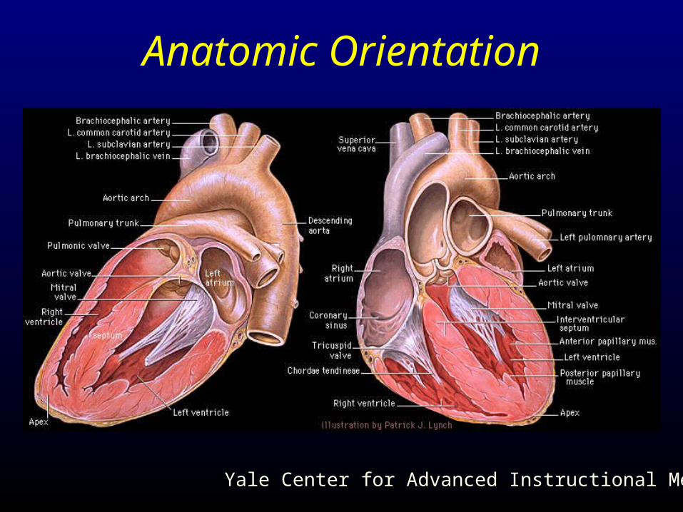
Anatomic Orientation
Yale Center for Advanced Instructional Media
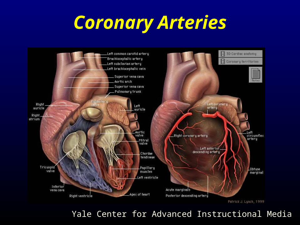
Coronary Arteries
Yale Center for Advanced Instructional Media

Motivation• Lack of blood flow to the myocardium due to
coronary artery disease leads progressively to ischemia, infarction, tissue necrosis, and tissue remodeling
• When blood flow is diminished to tissue, generally, its contractility is compromised
• Echocardiography is a very versatile imaging modality in measurement of LV contractility. But, it lacks methods for determining intramural deformations of the LV. The advantage of echocardiography however is that it is inexpensive.

Tagged MRI• Prior to conventional imaging, tissue magnetization is perturbed by application of RF and gradient pulses, resulting in saturation of signal from selected tissue locations
•Tag lines appear as a dark grid on images of soft tissue
• Data collection is synchronized with the ECG.
• As standard in MRI, image slices are acquired at precise 3-D locations relative to the magnet’s fixed coordinate system

SPAMM Tagged MRI Sequence
GGxx
RFRF
GGyy
GGzz
R
x
y

Tagged MRI: Short-Axis
Patient with old healed inferior MI
• • •
0 32 64 96 128 160
R RR
1000

Tagged MRI: Long-Axis
• • •
0 32 64 96 128 160
R RR
1000

Acquisition of Short-Axis Slices
• • •

Acquisition of Long-Axis Slices
• • •


B-Spline Models of Tag Planes

Periodic B-Splines
• Locality: Since each basis function has local support, movement of any control point only affects a small portion of the curve
• Continuity: Cubic B-spline curves are continuous everywhere
Cubic polynomial in u

4-D Cartesian B-Spline Model
Tustison and Amini, IEEE Trans. On Biomedical Engineering, 50(8), Aug. 2003
u
v
w

4-D B-Spline Model
After 4-D B-Spline fitting to tag data, we can easily extract
Myocardial beads
3-D Displacement fields
Myocardial strains

Myocardial Beads: Results

Displacement Fields
),,()0,,,(),,,( wvuSwvuSV
To generate displacement field, we subtract the 3-D solid at t = 0 from the 3-D solid at t = τ.
Tustison and Amini, IEEE Trans. On Biomedical Engineering, (50)8, Aug. 2003

Myocardial Strain
Positive strains correspond to elongation whereas negative strains correspond to compression.
Strain is a directionally dependent measure of percent change in length of a continuous deformable body

Myocardial Strain

Myocardial Strain

Myocardial Strain

Differential Element of Length
),,(: ZYXP
x
y
z),,(: dZZdYYdXXQ
)),,(),,,()),,,((: ZYXzZYXyZYXxp
),,(: dzzdyydxxq
),,(

zzyzx
yzyyx
xzxyx
2
1
2
12
1
2
12
1
2
1
Strain Calculation
n=e1: radial
n=e2:circumferential
n=e3: longitudinal
TnnL

222
2
1xxxxx
222
2
1yyyyy
222
2
1zzzzz
yxyxyxyxyxxy
zxzxzxzxzxxz
zyzyzyyyzyyz
Strain Calculation
),,( VMotion field:

Displacement Fields

Radial Strain

Circumferential Strains

Longitudinal Strains


Torsion: k2

Radial Thickening: k1

Simulated Tagged MRI Movie

Circumferential Strains

Displacement Fields

Strain Results – k1
+0.30
0.0
-0.30
Radial Strain Circumferential Strain

Sixteen Segment Model

Average Normal Strains
Diamonds: radial
Circles: circumferential
Squares: longitudinal

Average Normal Strains
Diamonds: radial
Circles: circumferential
Squares: longitudinal

Normal Strain Plots for Patient with old MI
Diamonds: radial
Circles: circumferential
Squares: longitudinal

Normal Strain Plots in Patient with old MI
Diamonds: radial
Circles: circumferential
Squares: longitudinal

www.amazon.comwww.borders.com

Intravascular Pressures from Phase-Contrast MR Velocities

Hemodynamic Significance of Arterial Stenoses
• Percent diameter stenosis does not generally translate to a measure of a stenosis’ significance
• Knowledge of pressure drop across a stenosis is the gold standard but is currently obtained invasively with a pressure catheter under X-ray angiography
• MRI has the tools for potentially determining pressure drops across vascular stenoses, accurately, and non-invasively.

Given 3-D pulsatile velocity data how can we determine pulsatile pressures ?
* Robust to noise
* Computationally efficient

Pressure and Velocity Field RelationsPressure and Velocity Field Relations---- Navier-Stokes’ Equation---- Navier-Stokes’ Equation
Convective Inertial ForcesConvective Inertial Forces Body force termBody force term
Viscous ForcesViscous Forces
PressurePressure
Pulsatile termPulsatile term

Phase-Contrast MRI
• An effective tool for blood flow quantification
• Phase-Contrast MRI may be used to acquire velocity images:
(a) At precise 3D slice locations
(b) Can quantify different components of
3D velocities

Phase-Contrast velocities in a 90% area stenosis phantomPhase-Contrast velocities in a 90% area stenosis phantom

Motion Induced Phase Shifts
ignore ignore PC-MRI

Phase Contrast Sequence
flow encode 1flow encode 1
A/DA/D
GGxx
RFRF
GGyy
GGzz
signalsignal

Phase Contrast Sequence
flow encode 2flow encode 2
A/DA/D
GGxx
RFRF
GGyy
GGzz
signalsignal

From Navier-Stokes to PressureFrom Navier-Stokes to Pressure1.1. Apply Navier-Stokes to noisy velocities to yieldApply Navier-Stokes to noisy velocities to yield2.2. Can it be integrated to yield pressure ? Can it be integrated to yield pressure ?
Noise-corrupted velocities in a straight pipe
is path-dependentis path-dependent
Can not be a true gradient vector field and therefore can not be integrated

From Noisy Gradient to PressureFrom Noisy Gradient to Pressure• Orthogonally project onto an integrable sub-
space where it can be integrated
Integrable sub-space
: true gradient vector field
Orthogonal Projection

Two Approaches to Orthogonal Projection
• Iterative solution to pressure-Poisson equation
• Direct harmonics-based orthogonal projection
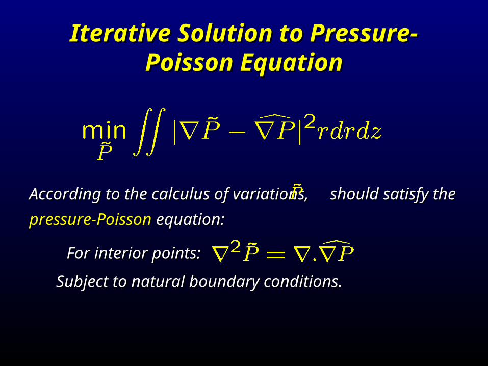
Iterative Solution to Pressure-Poisson Iterative Solution to Pressure-Poisson EquationEquation
According to the calculus of variations, should satisfy the According to the calculus of variations, should satisfy the
pressure-Poisson pressure-Poisson equation:equation:
For interior points:For interior points:
Subject to natural boundary conditions.Subject to natural boundary conditions.

Previous Work
• Song, et al. 1994, Yang, et al. 1996, Tyszeka et al. 2000, Thompson et al. 2003, and Moghaddam et al. 2004 all use iterative solution to the Pressure-Poisson equation to determine pressures from velocity data
• Predominantly, an iterative implementation based on the Gauss-Seidel iteration was used
• Moghaddam et al. used SOR to speed-up computations.

New Approach to Pressure Calculation: Harmonics-Based Orthogonal Projection

Frankot and Chellappa, IEEE PAMI, July 1988:Adopted a far more efficient basis function approach
Shape from Shading
1. Determine surface orientations from image brightness
2. To ensure integrability, noisy surface orientations are orthogonally projected into an integrable subspace
See for example, Ch. 11, Robot Vision by Horn

Expansion of Noisy Gradients With Integrable Basis Functions
Set of basis functions satisfying the Set of basis functions satisfying the integrability constraintintegrability constraint
WhereWhere::

Computing Pressure From Integrable Pressure Gradients
Following Frankot and Chellappa: Following Frankot and Chellappa:
When using Fourier basis functions

Using FFT
• STEP 1: perform FFT of to determine
• STEP 2: perform FFT of to determine
• STEP 3: Combine to determine
• STEP 4: Perform inverse FFT of to determine the relative pressure

Specific Problem in Computation of Intravascular Pressure
• Irregular geometry of blood vessels
Discontinuities along blood vessel boundaries
Discontinuities at in-flow and out-flow boundaries


Concentric and Eccentric Stenosis Geometries
90% Area Stenosis Phantoms90% Area Stenosis Phantoms
• 50%, 75%, 90% concentric area stenosis phantoms have been fabricated
• These exact geometries are used in FLUENT CFD code for flow simulation

Experimental Flow SystemExperimental Flow System

Validations
1. Used FLUENT CFD package to generate velocity fields and pressure maps for geometries and flow rates of interest.
2. Varying amounts of additive noise was added to FLUENT velocities and then fed to the algorithm. Calculated pressures were compared with FLUENT pressures.
3. In-vitro PC MR data from an experimental flow system were collected and fed to the algorithm. Calculated pressure maps were compared with FLUENT pressures.

Validation Validation ---- on ---- on 3-D Axisymmetric FLUENT Velocities3-D Axisymmetric FLUENT Velocities
Model
Q=10 (ml/s)
Q=15 (ml/s)
Q=20 (ml/s)
50% 3.24 5.10 6.31
75% 4.12 5.26 5.95
90% 6.79 7.26 7.53
Relative RMS Error (RError) between calculated pressures using Fluent velocities with Fluent pressures (%) – no noise, constant flow
Model
Q=10 (ml/s)
Q=15 (ml/s)
Q=20 (ml/s)
50% 7.13 4.29 3.71
75% 10.68 10.60 9.60
90% 5.11 7.55 8.92Harmonics-Based Orthogonal Projection Iterative Solution to Pressure-Poisson Equation

ValidationValidation ---- on ---- on 3-D Axisymmetric FLUENT Velocities3-D Axisymmetric FLUENT Velocities
Model
Q=10 (ml/s)
Q=15 (ml/s)
Q=20 (ml/s)
50% 3.30 3.23 3.23
75% 4.25 4.23 3.25
90% 3.25 3.27 3.26
CPU time on a Sun SPARC 10 when computing pressures (seconds):
Model
Q=10 (ml/s)
Q=15 (ml/s)
Q=20 (ml/s)
50% 7.91 10.81 13.87
75% 7.18 5.93 5.82
90% 154.3 154.5 154.3
Harmonics-Based Orthogonal Projection Iterative Solution to Pressure-Poisson Equation

Noise Test on 3-D Axisymmetric FLUENT Data
Relative RMS Error (RError) between calculated pressures using Fluent velocities with Fluent pressures for the 90% area stenosis phantom, Q=20 ml/s (constant flow)
RError of non-iterative method
RError of iterative method
0.02 13% 11.32%
0.04 18% 14.67%
0.06 28.14% 23.86%
0.4 49.97% 299.72%
0.6 71.42% N/A

In-Vitro Pressure Profiles (from MRI) Along the Axis In-Vitro Pressure Profiles (from MRI) Along the Axis of Symmetry of Stenosis Phantoms: Constant Flowof Symmetry of Stenosis Phantoms: Constant Flow
50%
75%
90%
Q=10 ml/s Q=15 ml/s Q=20 ml/s
Center ofCenter ofStenosesStenoses

Pulsatile Flow
Simulation performed by Juan Cebral using FEFLOSimulation performed by Juan Cebral using FEFLO

Noise Test on 3-D+t Simulated Pulsatile Velocity Data
Stenosis Model
RError of non-Iterative Method
RError of Iterative Method
75% eccentric 13.00% 32.91%
75% concentric 10.20% 23.87%
90% eccentric 10.29% 17.23%
90% concentric
13.73% 22.58%
Relative RMS Error (RError) between calculated pressures using noise corrupted FEFLO pulsatile velocities with FEFLO pressures = 0.03

Percent stenosis can be quantified from the MIP. The goal of this project is Percent stenosis can be quantified from the MIP. The goal of this project is to determine whether the stenoses are hemodynamically significant requiring to determine whether the stenoses are hemodynamically significant requiring invasive surgery/intervention.invasive surgery/intervention.

Geometry from Level-Set Evolution
Chen and Amini, IEEE Trans. On Medical Imaging, Vol. 23, No. 10, Oct. 2004

Level-Set Segmentation
• Perform 3-D level set evolution, using a speed function derived from the enhanced image

Conclusions
Phase-Contrast MRI
Non-invasive measurement of intravascular pressures from Phase-Contrast MRI
Tagged MRI
Non-invasive measurement of myocardial strain maps
Visualization of myocardial beads

Acknowledgements
• Nasser Fatouraee• Nick Tustison• Jian Chen• Abbas Moghaddam• Geoff Behrens
• NIH, BJH Foundation

Useful Links/Contact Information
• Amir Amini [email protected] until July 15
• General information about ECE and forms
http://www.ece.louisville.edu/gen_forms.html
• On-line application for doctoral degree http://graduate.louisville.edu/app/