IM832-A PRECISION TIG 185 December, 2006
38
• Sales and Service through Subsidiaries and Distributors Worldwide • Cleveland, Ohio 44117-1199 U.S.A. TEL: 216.481.8100 FAX: 216.486.1751 WEB SITE: www.lincolnelectric.com • World's Leader in Welding and Cutting Products • OPERATOR?S MANUAL IM832-A December, 2006 Safety Depends on You Lincoln arc welding and cutting equipment is designed and built with safety in mind. However, your overall safety can be increased by proper installation ... and thought- ful operation on your part. DO NOT INSTALL, OPERATE OR REPAIR THIS EQUIPMENT WITHOUT READING THIS MANUAL AND THE SAFETY PRECAUTIONS CONTAINED THROUGHOUT. And, most importantly, think before you act and be careful. For use with machines having Code Numbers: Copyright © 2006 Lincoln Global Inc. PRECISION TIG 185 11105, 11106, 11107 11108, 11109 IP 21S This manual covers equipment which is no longer in production by The Lincoln Electric Co. Specifications and availability of optional features may have changed.
Transcript of IM832-A PRECISION TIG 185 December, 2006

• Sales and Service through Subsidiaries and Distributors Worldwide •
Cleveland, Ohio 44117-1199 U.S.A. TEL: 216.481.8100 FAX: 216.486.1751 WEB SITE: www.lincolnelectric.com
• World's Leader in Welding and Cutting Products •
OPERATOR?S MANUAL
IM832-ADecember, 2006
Safety Depends on YouLincoln arc welding and cuttingequipment is designed and builtwith safety in mind. However, youroverall safety can be increased byproper installation ... and thought-ful operation on your part. DONOT INSTALL, OPERATE OR
REPAIR THIS EQUIPMENT
WITHOUT READING THIS
MANUAL AND THE SAFETY
PRECAUTIONS CONTAINED
THROUGHOUT. And, mostimportantly, think before you actand be careful.
For use with machines having Code Numbers:
Copyright © 2006 Lincoln Global Inc.
PRECISION TIG 18511105, 11106, 11107
11108, 11109
IP 21S
This manual covers equipment which is no longer in production by The Lincoln Electric Co. Speci�cations and availability of optional features may have changed.

FOR ENGINEpowered equipment.
1.a. Turn the engine off before troubleshooting and maintenancework unless the maintenance work requires it to be running.
____________________________________________________1.b. Operate engines in open, well-ventilated
areas or vent the engine exhaust fumesoutdoors.
____________________________________________________1.c. Do not add the fuel near an open flame
welding arc or when the engine is running.Stop the engine and allow it to cool beforerefueling to prevent spilled fuel from vaporiz-ing on contact with hot engine parts andigniting. Do not spill fuel when filling tank. Iffuel is spilled, wipe it up and do not startengine until fumes have been eliminated.
____________________________________________________1.d. Keep all equipment safety guards, covers and devices in
position and in good repair.Keep hands, hair, clothing andtools away from V-belts, gears, fans and all other movingparts when starting, operating or repairing equipment.
____________________________________________________
1.e. In some cases it may be necessary to remove safetyguards to perform required maintenance. Removeguards only when necessary and replace them when themaintenance requiring their removal is complete.Always use the greatest care when working near movingparts.
___________________________________________________1.f. Do not put your hands near the engine fan.
Do not attempt to override the governor oridler by pushing on the throttle control rodswhile the engine is running.
___________________________________________________1.g. To prevent accidentally starting gasoline engines while
turning the engine or welding generator during maintenancework, disconnect the spark plug wires, distributor cap ormagneto wire as appropriate.
iSAFETYi
ARC WELDING CAN BE HAZARDOUS. PROTECT YOURSELF AND OTHERS FROM POSSIBLE SERIOUS INJURY OR DEATH.
KEEP CHILDREN AWAY. PACEMAKER WEARERS SHOULD CONSULT WITH THEIR DOCTOR BEFORE OPERATING.
Read and understand the following safety highlights. For additional safety information, it is strongly recommended that youpurchase a copy of “Safety in Welding & Cutting - ANSI Standard Z49.1” from the American Welding Society, P.O. Box351040, Miami, Florida 33135 or CSA Standard W117.2-1974. A Free copy of “Arc Welding Safety” booklet E205 is availablefrom the Lincoln Electric Company, 22801 St. Clair Avenue, Cleveland, Ohio 44117-1199.
BE SURE THAT ALL INSTALLATION, OPERATION, MAINTENANCE AND REPAIR PROCEDURES ARE
PERFORMED ONLY BY QUALIFIED INDIVIDUALS.
WARNING
Mar ʻ95
ELECTRIC AND
MAGNETIC FIELDS
may be dangerous
2.a. Electric current flowing through any conductor causeslocalized Electric and Magnetic Fields (EMF). Weldingcurrent creates EMF fields around welding cables andwelding machines
2.b. EMF fields may interfere with some pacemakers, andwelders having a pacemaker should consult their physicianbefore welding.
2.c. Exposure to EMF fields in welding may have other healtheffects which are now not known.
2.d. All welders should use the following procedures in order tominimize exposure to EMF fields from the welding circuit:
2.d.1. Route the electrode and work cables together - Securethem with tape when possible.
2.d.2. Never coil the electrode lead around your body.
2.d.3. Do not place your body between the electrode andwork cables. If the electrode cable is on your rightside, the work cable should also be on your right side.
2.d.4. Connect the work cable to the workpiece as close aspossible to the area being welded.
2.d.5. Do not work next to welding power source.
1.h. To avoid scalding, do not remove theradiator pressure cap when the engine ishot.
CALIFORNIA PROPOSITION 65 WARNINGS
Diesel engine exhaust and some of its constituentsare known to the State of California to cause can-cer, birth defects, and other reproductive harm.
The engine exhaust from this product containschemicals known to the State of California to causecancer, birth defects, or other reproductive harm.
The Above For Diesel Engines The Above For Gasoline Engines

iiSAFETYii
ARC RAYS can burn.4.a. Use a shield with the proper filter and cover
plates to protect your eyes from sparks andthe rays of the arc when welding or observingopen arc welding. Headshield and filter lensshould conform to ANSI Z87. I standards.
4.b. Use suitable clothing made from durable flame-resistantmaterial to protect your skin and that of your helpers fromthe arc rays.
4.c. Protect other nearby personnel with suitable, non-flammablescreening and/or warn them not to watch the arc nor exposethemselves to the arc rays or to hot spatter or metal.
ELECTRIC SHOCK can
kill.3.a. The electrode and work (or ground) circuits
are electrically “hot” when the welder is on.Do not touch these “hot” parts with your bareskin or wet clothing. Wear dry, hole-free
gloves to insulate hands.
3.b. Insulate yourself from work and ground using dry insulation.Make certain the insulation is large enough to cover your fullarea of physical contact with work and ground.
In addition to the normal safety precautions, if welding
must be performed under electrically hazardous
conditions (in damp locations or while wearing wet
clothing; on metal structures such as floors, gratings or
scaffolds; when in cramped positions such as sitting,
kneeling or lying, if there is a high risk of unavoidable or
accidental contact with the workpiece or ground) use
the following equipment:
• Semiautomatic DC Constant Voltage (Wire) Welder.
• DC Manual (Stick) Welder.
• AC Welder with Reduced Voltage Control.
3.c. In semiautomatic or automatic wire welding, the electrode,electrode reel, welding head, nozzle or semiautomaticwelding gun are also electrically “hot”.
3.d. Always be sure the work cable makes a good electricalconnection with the metal being welded. The connectionshould be as close as possible to the area being welded.
3.e. Ground the work or metal to be welded to a good electrical(earth) ground.
3.f. Maintain the electrode holder, work clamp, welding cable andwelding machine in good, safe operating condition. Replacedamaged insulation.
3.g. Never dip the electrode in water for cooling.
3.h. Never simultaneously touch electrically “hot” parts ofelectrode holders connected to two welders because voltagebetween the two can be the total of the open circuit voltageof both welders.
3.i. When working above floor level, use a safety belt to protectyourself from a fall should you get a shock.
3.j. Also see Items 6.c. and 8.
FUMES AND GASES
can be dangerous.5.a. Welding may produce fumes and gases
hazardous to health. Avoid breathing thesefumes and gases. When welding, keepyour head out of the fume. Use enoughventilation and/or exhaust at the arc to keep
fumes and gases away from the breathing zone. When
welding with electrodes which require special
ventilation such as stainless or hard facing (see
instructions on container or MSDS) or on lead or
cadmium plated steel and other metals or coatings
which produce highly toxic fumes, keep exposure as
low as possible and below Threshold Limit Values (TLV)
using local exhaust or mechanical ventilation. In
confined spaces or in some circumstances, outdoors, a
respirator may be required. Additional precautions are
also required when welding on galvanized steel.
5. b. The operation of welding fume control equipment is affectedby various factors including proper use and positioning ofthe equipment, maintenance of the equipment and the spe-cific welding procedure and application involved. Workerexposure level should be checked upon installation andperiodically thereafter to be certain it is within applicableOSHA PEL and ACGIH TLV limits.
5.c. Do not weld in locations near chlorinated hydrocarbon vaporscoming from degreasing, cleaning or spraying operations.The heat and rays of the arc can react with solvent vapors toform phosgene, a highly toxic gas, and other irritating prod-ucts.
5.d. Shielding gases used for arc welding can displace air andcause injury or death. Always use enough ventilation,especially in confined areas, to insure breathing air is safe.
5.e. Read and understand the manufacturerʼs instructions for thisequipment and the consumables to be used, including thematerial safety data sheet (MSDS) and follow youremployerʼs safety practices. MSDS forms are available fromyour welding distributor or from the manufacturer.
5.f. Also see item 1.b.
AUG 06

FOR ELECTRICALLYpowered equipment.
8.a. Turn off input power using the disconnectswitch at the fuse box before working onthe equipment.
8.b. Install equipment in accordance with the U.S. NationalElectrical Code, all local codes and the manufacturerʼsrecommendations.
8.c. Ground the equipment in accordance with the U.S. NationalElectrical Code and the manufacturerʼs recommendations.
CYLINDER may explode
if damaged.7.a. Use only compressed gas cylinders
containing the correct shielding gas for theprocess used and properly operatingregulators designed for the gas and
pressure used. All hoses, fittings, etc. should be suitable forthe application and maintained in good condition.
7.b. Always keep cylinders in an upright position securelychained to an undercarriage or fixed support.
7.c. Cylinders should be located:• Away from areas where they may be struck or subjected tophysical damage.
• A safe distance from arc welding or cutting operations andany other source of heat, sparks, or flame.
7.d. Never allow the electrode, electrode holder or any otherelectrically “hot” parts to touch a cylinder.
7.e. Keep your head and face away from the cylinder valve outletwhen opening the cylinder valve.
7.f. Valve protection caps should always be in place and handtight except when the cylinder is in use or connected foruse.
7.g. Read and follow the instructions on compressed gascylinders, associated equipment, and CGA publication P-l,“Precautions for Safe Handling of Compressed Gases inCylinders,” available from the Compressed Gas Association1235 Jefferson Davis Highway, Arlington, VA 22202.
iiiSAFETYiii
Mar ʻ95
WELDING SPARKS cancause fire or explosion.6.a. Remove fire hazards from the welding area.
If this is not possible, cover them to preventthe welding sparks from starting a fire.Remember that welding sparks and hot
materials from welding can easily go through small cracksand openings to adjacent areas. Avoid welding nearhydraulic lines. Have a fire extinguisher readily available.
6.b. Where compressed gases are to be used at the job site,special precautions should be used to prevent hazardoussituations. Refer to “Safety in Welding and Cutting” (ANSIStandard Z49.1) and the operating information for theequipment being used.
6.c. When not welding, make certain no part of the electrodecircuit is touching the work or ground. Accidental contactcan cause overheating and create a fire hazard.
6.d. Do not heat, cut or weld tanks, drums or containers until theproper steps have been taken to insure that such procedureswill not cause flammable or toxic vapors from substancesinside. They can cause an explosion even though they havebeen “cleaned”. For information, purchase “RecommendedSafe Practices for the Preparation for Welding and Cutting ofContainers and Piping That Have Held HazardousSubstances”, AWS F4.1 from the American Welding Society(see address above).
6.e. Vent hollow castings or containers before heating, cutting orwelding. They may explode.
6.f. Sparks and spatter are thrown from the welding arc. Wear oilfree protective garments such as leather gloves, heavy shirt,cuffless trousers, high shoes and a cap over your hair. Wearear plugs when welding out of position or in confined places.Always wear safety glasses with side shields when in awelding area.
6.g. Connect the work cable to the work as close to the weldingarea as practical. Work cables connected to the buildingframework or other locations away from the welding areaincrease the possibility of the welding current passingthrough lifting chains, crane cables or other alternate cir-cuits. This can create fire hazards or overheat lifting chainsor cables until they fail.
6.h. Also see item 1.c.

ivSAFETYiv
Mar. ʻ93
PRÉCAUTIONS DE SÛRETÉ
Pour votre propre protection lire et observer toutes les instructionset les précautions de sûreté specifiques qui parraissent dans cemanuel aussi bien que les précautions de sûreté générales suiv-antes:
Sûreté Pour Soudage A LʼArc
1. Protegez-vous contre la secousse électrique:
a. Les circuits à lʼélectrode et à la piéce sont sous tensionquand la machine à souder est en marche. Eviter toujourstout contact entre les parties sous tension et la peau nueou les vétements mouillés. Porter des gants secs et sanstrous pour isoler les mains.
b. Faire trés attention de bien sʼisoler de la masse quand onsoude dans des endroits humides, ou sur un planchermetallique ou des grilles metalliques, principalement dansles positions assis ou couché pour lesquelles une grandepartie du corps peut être en contact avec la masse.
c. Maintenir le porte-électrode, la pince de masse, le câblede soudage et la machine à souder en bon et sûr étatdefonctionnement.
d.Ne jamais plonger le porte-électrode dans lʼeau pour lerefroidir.
e. Ne jamais toucher simultanément les parties sous tensiondes porte-électrodes connectés à deux machines à souderparce que la tension entre les deux pinces peut être letotal de la tension à vide des deux machines.
f. Si on utilise la machine à souder comme une source decourant pour soudage semi-automatique, ces precautionspour le porte-électrode sʼapplicuent aussi au pistolet desoudage.
2. Dans le cas de travail au dessus du niveau du sol, se protégercontre les chutes dans le cas ou on recoit un choc. Ne jamaisenrouler le câble-électrode autour de nʼimporte quelle partiedu corps.
3. Un coup dʼarc peut être plus sévère quʼun coup de soliel,donc:
a. Utiliser un bon masque avec un verre filtrant appropriéainsi quʼun verre blanc afin de se protéger les yeux du ray-onnement de lʼarc et des projections quand on soude ouquand on regarde lʼarc.
b. Porter des vêtements convenables afin de protéger lapeau de soudeur et des aides contre le rayonnement delʻarc.
c. Protéger lʼautre personnel travaillant à proximité ausoudage à lʼaide dʼécrans appropriés et non-inflammables.
4. Des gouttes de laitier en fusion sont émises de lʼarc desoudage. Se protéger avec des vêtements de protection libresde lʼhuile, tels que les gants en cuir, chemise épaisse, pan-talons sans revers, et chaussures montantes.
5. Toujours porter des lunettes de sécurité dans la zone desoudage. Utiliser des lunettes avec écrans lateraux dans leszones où lʼon pique le laitier.
6. Eloigner les matériaux inflammables ou les recouvrir afin deprévenir tout risque dʼincendie dû aux étincelles.
7. Quand on ne soude pas, poser la pince à une endroit isolé dela masse. Un court-circuit accidental peut provoquer unéchauffement et un risque dʼincendie.
8. Sʼassurer que la masse est connectée le plus prés possiblede la zone de travail quʼil est pratique de le faire. Si on placela masse sur la charpente de la construction ou dʼautresendroits éloignés de la zone de travail, on augmente le risquede voir passer le courant de soudage par les chaines de lev-age, câbles de grue, ou autres circuits. Cela peut provoquerdes risques dʼincendie ou dʼechauffement des chaines et descâbles jusquʼà ce quʼils se rompent.
9. Assurer une ventilation suffisante dans la zone de soudage.Ceci est particuliérement important pour le soudage de tôlesgalvanisées plombées, ou cadmiées ou tout autre métal quiproduit des fumeés toxiques.
10. Ne pas souder en présence de vapeurs de chlore provenantdʼopérations de dégraissage, nettoyage ou pistolage. Lachaleur ou les rayons de lʼarc peuvent réagir avec les vapeursdu solvant pour produire du phosgéne (gas fortement toxique)ou autres produits irritants.
11. Pour obtenir de plus amples renseignements sur la sûreté,voir le code “Code for safety in welding and cutting” CSAStandard W 117.2-1974.
PRÉCAUTIONS DE SÛRETÉ POUR
LES MACHINES À SOUDER À
TRANSFORMATEUR ET À
REDRESSEUR
1. Relier à la terre le chassis du poste conformement au code delʼélectricité et aux recommendations du fabricant. Le dispositifde montage ou la piece à souder doit être branché à unebonne mise à la terre.
2. Autant que possible, Iʼinstallation et lʼentretien du poste seronteffectués par un électricien qualifié.
3. Avant de faires des travaux à lʼinterieur de poste, la debranch-er à lʼinterrupteur à la boite de fusibles.
4. Garder tous les couvercles et dispositifs de sûreté à leurplace.

vSAFETYv

viSAFETYvi

Thank You for selecting a QUALITY product by Lincoln Electric. We want youto take pride in operating this Lincoln Electric Company product••• as much pride as we have in bringing this product to you!
Read this Operators Manual completely before attempting to use this equipment. Save this manual and keep ithandy for quick reference. Pay particular attention to the safety instructions we have provided for your protection.The level of seriousness to be applied to each is explained below:
WARNING
This statement appears where the information must be followed exactly to avoid serious personal injury orloss of life.
This statement appears where the information must be followed to avoid minor personal injury or damage to
this equipment.
CAUTION
Please Examine Carton and Equipment For Damage ImmediatelyWhen this equipment is shipped, title passes to the purchaser upon receipt by the carrier. Consequently, Claimsfor material damaged in shipment must be made by the purchaser against the transportation company at thetime the shipment is received.
Please record your equipment identification information below for future reference. This information can befound on your machine nameplate.
Product _________________________________________________________________________________
Model Number ___________________________________________________________________________
Code Number or Date Code_________________________________________________________________
Serial Number____________________________________________________________________________
Date Purchased___________________________________________________________________________
Where Purchased_________________________________________________________________________
Whenever you request replacement parts or information on this equipment, always supply the information youhave recorded above. The code number is especially important when identifying the correct replacement parts.
viivii
On-Line Product Registration
- Register your machine with Lincoln Electric either via fax or over the Internet.
• For faxing: Complete the form on the back of the warranty statement included in the literature packetaccompanying this machine and fax the form per the instructions printed on it.
• For On-Line Registration: Go to our WEB SITE at www.lincolnelectric.com. Choose “Quick Links” and then“Product Registration”. Please complete the form and submit your registration.

viii viii TABLE OF CONTENTSPage
Installation.......................................................................................................................Section A
Technical Specifications ................................................................................................A-1,A-2Safety Precautions ...............................................................................................................A-3
Select Suitable Location................................................................................................A-3Grinding.........................................................................................................................A-3Stacking ........................................................................................................................A-3Tilting.............................................................................................................................A-3Lifting and Moving .........................................................................................................A-3Tilting.............................................................................................................................A-3Environmental Rating....................................................................................................A-3
Machine Grounding and High Frequency Interference Protection................................A-3, A-4Input Connections .........................................................................................................A-4Input Reconnect Procedure ..........................................................................................A-5
Output Connections..............................................................................................................A-5Connections For Tig (GTAW) Welding..........................................................................A-5Tig Torch Connections ..................................................................................................A-5Work Cable Connections ..............................................................................................A-5Shielding Gas Connection.............................................................................................A-6Remote Control Connection..........................................................................................A-6
Connections For Stick (SMAW) Welding .............................................................................A-6Stick Electrode Cable and Work Cable Connection......................................................A-6
________________________________________________________________________________Operation.........................................................................................................................Section B
Safety Precautions ...............................................................................................................B-1Graphic Symbols ..................................................................................................................B-1Product Description ..............................................................................................................B-1
Recommended Processes and Equipment...................................................................B-2Recommended Processes.. ..........................................................................................B-2Process Limitations ......................................................................................................B-2Recommended Equipment/Interface.............................................................................B-2Equipment Limitations...................................................................................................B-2
Welding Capability................................................................................................................B-2Controls and Settings ...................................................................................................B-3, B-4Operating Steps ...................................................................................................................B-4
Welding in TIG Mode ....................................................................................................B-4Pulse TIG Mode ............................................................................................................B-4Remote Control Operation ............................................................................................B-5Benefits of the Precision TIG 185 .................................................................................B-5
Welding in Stick Mode..........................................................................................................B-6________________________________________________________________________________
Accessories .....................................................................................................Section C
Factory Installed Options.......................................................................................C-1Field Installed Options...........................................................................................C-1
________________________________________________________________________Maintenance ....................................................................................................Section D
Safety Precautions ................................................................................................D-1Routine and Periodic Maintenance........................................................................D-1
________________________________________________________________________Troubleshooting ..............................................................................................Section E
Safety Precautions.................................................................................................E-1How to Use Troubleshooting Guide.......................................................................E-1Troubleshooting ..................................................................................E-2 THRU E-7
________________________________________________________________________Diagrams .........................................................................................................Section F
Wiring Diagram ......................................................................................................F-1Dimension Print......................................................................................................F-2
________________________________________________________________________Parts List .................................................................................................P499,P210,P66
A-1INSTALLATION
PRECISION TIG 185
A-1
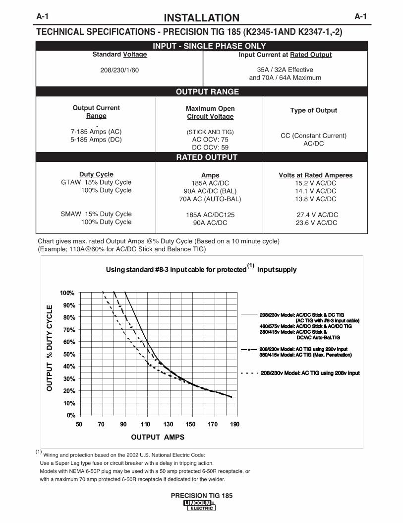
TECHNICAL SPECIFICATIONS - PRECISION TIG 185 (K2345-1AND K2347-1,-2)
Volts at Rated Amperes15.2 V AC/DC14.1 V AC/DC13.8 V AC/DC
27.4 V AC/DC23.6 V AC/DC
Type of Output
CC (Constant Current)AC/DC
Amps185A AC/DC
90A AC/DC (BAL)70A AC (AUTO-BAL)
185A AC/DC12590A AC/DC
Maximum Open Circuit Voltage
(STICK AND TIG)
AC OCV: 75DC OCV: 59
Input Current at Rated Output
35A / 32A Effectiveand 70A / 64A Maximum
Duty CycleGTAW 15% Duty Cycle
100% Duty Cycle
SMAW 15% Duty Cycle100% Duty Cycle
Output Current Range
7-185 Amps (AC)5-185 Amps (DC)
Standard Voltage
208/230/1/60
INPUT - SINGLE PHASE ONLY
OUTPUT RANGE
RATED OUTPUT
Chart gives max. rated Output Amps @% Duty Cycle (Based on a 10 minute cycle)(Example; 110A@60% for AC/DC Stick and Balance TIG)
Using standard #8-3 input cable for protected(1) input supply
0%10%20%30%40%50%60%70%80%90%100%
50 70 90 110 130 150 170 190
208/230v Model: 208/230v Model: AC/DC Stick & DC AC/DC Stick & DC TIGTIG (AC (AC TIG with #6-3 input cable)TIG with #6-3 input cable)460/575v Model: 460/575v Model: AC/DC Stick & AC/DC Stick & AC/DC AC/DC TIGTIG380/415v Model: 380/415v Model: AC/DC Stick & AC/DC Stick & DC/AC DC/AC Auto-Bal.TIGAuto-Bal.TIG208/230v Model: 208/230v Model: AC AC TIG using 230v inputTIG using 230v input380/415v Model: 380/415v Model: AC AC TIG (Max. Penetration)TIG (Max. Penetration)208/230v Model: 208/230v Model: AC AC TIG using 208v inputTIG using 208v input
OUTPUT AMPS
OUTPUT % D
UTY CYCLE
Using standard #8-3 input cable for protected(1)
input supply
0%
10%
20%
30%
40%
50%
60%
70%
80%
90%
100%
50 70 90 110 130 150 170 190
208/230v Model: 208/230v Model: AC/DC Stick & DC AC/DC Stick & DC TIGTIG (AC (AC TIG with #6-3 input cable)TIG with #6-3 input cable)460/575v Model: 460/575v Model: AC/DC Stick & AC/DC Stick & AC/DC AC/DC TIGTIG380/415v Model: 380/415v Model: AC/DC Stick & AC/DC Stick & DC/AC DC/AC Auto-Bal.TIGAuto-Bal.TIG
208/230v Model: 208/230v Model: AC AC TIG using 230v inputTIG using 230v input380/415v Model: 380/415v Model: AC AC TIG (Max. Penetration)TIG (Max. Penetration)
208/230v Model: 208/230v Model: AC AC TIG using 208v inputTIG using 208v input
OUTPUT AMPS
OU
TP
UT
%
DU
TY
CY
CL
E
(1)Wiring and protection based on the 2002 U.S. National Electric Code:
Use a Super Lag type fuse or circuit breaker with a delay in tripping action.
Models with NEMA 6-50P plug may be used with a 50 amp protected 6-50R receptacle, or
with a maximum 70 amp protected 6-50R receptacle if dedicated for the welder.

A-2INSTALLATION
PRECISION TIG 185
A-2
TECHNICAL SPECIFICATIONS - CANADIAN (K2345-2), INTERNATIONAL K2346-1)
MODEL HEIGHT WIDTH DEPTH WEIGHT
PHYSICAL DIMENSIONS(2)
Weld Voltage (NEMA)
27.4 V 23.6 V
15.2 V 14.1 V
Output Type
CC (Constant Current)AC or DC
Weld Current
185 A AC/DC90 A AC/DC
185 A AC/DC90 A AC/DC (Auto-Bal.)
Weld Current
7-185 A (AC)5-185 A (DC).
Process Duty Cycle*.
SMAW15%100%GTAW15%100%
Max. OCV.
74 V (AC)59 V (DC)
OUTPUT RANGE
RATED OUTPUT
Machine Only (K2345-1,-2)
(K2346-1)Ready-Pak(K2347-1)
Ready-PakW/Cart (K2347-2)
20.71 in.526 mm
20.71 in.526 mm
31.24 in.794 mm
14.48 in.368 mm
14.48 in.368 mm
19.81 in.503 mm
25.62 in.751 mm
25.62 in.651 mm
38.01 in.966 mm
Approx. 192 lbs.87.1 kgs
Approx. 212lbs..96.2 kgs.
Approx. 258lbs.117.0 kgs.
(2) Dimensions are without Lift Eyebolt and Torch Holder
Power Factor
0.62 Min.
Idle Current
1.3 A/1.0 A Max.
Current
16 A/13 A Effective32 A/26 A Max.
Voltage/Phase/Freq.
460/575/1/60
K2345-2 INPUT (at Rated Output)
K2346-1 INPUT (at Rated Output)
Power Factor
0.62 Min.
Idle Current
1.3 A/1.0 A Max.
Current
19 A/18 A Effective39 A/37 A Max.
Voltage/Phase/Freq.
380/400-415/1/50/60
* Based on a 10 minute cycle.
N80
A-3INSTALLATION
PRECISION TIG 185
A-3
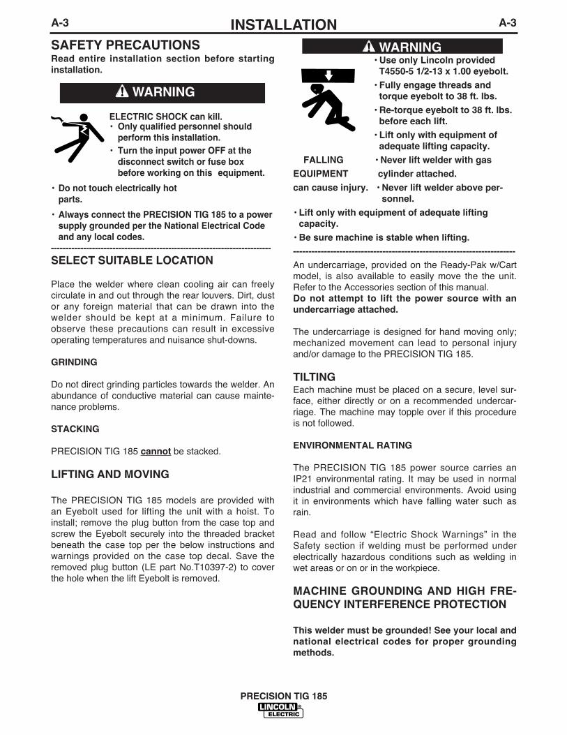
SAFETY PRECAUTIONS
SELECT SUITABLE LOCATION
Place the welder where clean cooling air can freelycirculate in and out through the rear louvers. Dirt, dustor any foreign material that can be drawn into thewelder should be kept at a minimum. Failure toobserve these precautions can result in excessiveoperating temperatures and nuisance shut-downs.
GRINDING
Do not direct grinding particles towards the welder. Anabundance of conductive material can cause mainte-nance problems.
STACKING
PRECISION TIG 185 cannot be stacked.
LIFTING AND MOVING
The PRECISION TIG 185 models are provided withan Eyebolt used for lifting the unit with a hoist. Toinstall; remove the plug button from the case top andscrew the Eyebolt securely into the threaded bracketbeneath the case top per the below instructions andwarnings provided on the case top decal. Save theremoved plug button (LE part No.T10397-2) to coverthe hole when the lift Eyebolt is removed.
An undercarriage, provided on the Ready-Pak w/Cartmodel, is also available to easily move the the unit.Refer to the Accessories section of this manual. Do not attempt to lift the power source with an
undercarriage attached.
The undercarriage is designed for hand moving only;mechanized movement can lead to personal injuryand/or damage to the PRECISION TIG 185.
TILTINGEach machine must be placed on a secure, level sur-face, either directly or on a recommended undercar-riage. The machine may topple over if this procedureis not followed.
ENVIRONMENTAL RATING
The PRECISION TIG 185 power source carries anIP21 environmental rating. It may be used in normalindustrial and commercial environments. Avoid usingit in environments which have falling water such asrain.
Read and follow “Electric Shock Warnings” in theSafety section if welding must be performed underelectrically hazardous conditions such as welding inwet areas or on or in the workpiece.
MACHINE GROUNDING AND HIGH FRE-
QUENCY INTERFERENCE PROTECTION
This welder must be grounded! See your local and
national electrical codes for proper grounding
methods.
ELECTRIC SHOCK can kill.• Only qualified personnel should
perform this installation.
• Turn the input power OFF at the
disconnect switch or fuse box
before working on this equipment.
• Do not touch electrically hot
parts.
• Always connect the PRECISION TIG 185 to a power
supply grounded per the National Electrical Code
and any local codes.
---------------------------------------------------------------------------
WARNING
Read entire installation section before starting
installation.• Use only Lincoln provided
T4550-5 1/2-13 x 1.00 eyebolt.
• Fully engage threads and
torque eyebolt to 38 ft. lbs.
• Re-torque eyebolt to 38 ft. lbs.
before each lift.
• Lift only with equipment of
adequate lifting capacity.
FALLING • Never lift welder with gas
EQUIPMENT cylinder attached.
can cause injury. • Never lift welder above per-
sonnel.
• Lift only with equipment of adequate lifting
capacity.
• Be sure machine is stable when lifting.
------------------------------------------------------------------------
WARNING

A-4INSTALLATION
PRECISION TIG 185
A-4
The high frequency generator, being similar to a radiotransmitter, may cause radio, TV and electronic equip-ment interference problems. These problems may bethe result of radiated interference. Proper groundingmethods can reduce or eliminate radiated interfer-ence.
Radiated interference can develop in the followingfour ways:
1. Direct interference radiated from the welder.2. Direct interference radiated from the welding leads.3. Direct interference radiated from feedback into the
power lines.4. Interference from re-radiation of “pickup” by
ungrounded metallic objects.
Keeping these contributing factors in mind, installing equipment per the following instructions should mini-mize problems.
1. Keep the welder power supply lines as short aspossible. Input leads within 50 feet (15.2m) of thewelder should be enclosed in rigid metallic conduitor equivalent shielding. There should be good elec-trical contact between this conduit and the weldercase ground. Both ends of the conduit should beconnected to a driven ground and the entire lengthshould be continuous.
2. Keep the work and electrode leads as short as pos-sible and as close together as possible. Lengthsshould not exceed 25 ft (7.6m). Tape the leadstogether when practical.
3. Be sure the torch and work cable rubber coveringsare free of cuts and cracks that allow high frequen-cy leakage.
4. Keep the torch in good repair and all connectionstight to reduce high frequency leakage.
5. The work piece must be connected to an earthground close to the work clamp, using one of thefollowing methods:
a) A metal underground water pipe in direct contactwith the earth for ten feet or more.
b) A 3/4” (19mm) galvanized pipe or a 5/8”(16mm)solid galvanized iron, steel or copper roddriven at least eight feet into the ground.
The ground should be securely made and the ground-ing cable should be as short as possible using cableof the same size as the work cable, or larger.Grounding to the building frame electrical conduit oralong pipe system can result in re-radiation, effectivelymaking these members radiating antennas.
6. Keep cover and all screws securely in place.
7. Electrical conductors within 50 ft (15.2m) of thewelder should be enclosed in grounded rigid metal-lic conduit or equivalent shielding, wherever possi-ble. Flexible metallic conduit is generally not suit-able.
8. When the welder is enclosed in a metal building,themetal building should be connected to several goodearth driven electrical grounds (as in 5 (b) above)around the periphery of the building.
Failure to observe these recommended installationprocedures can cause radio or TV and electronicequipment interference problems and result in unsat-isfactory welding performance resulting from lost highfrequency power.
INPUT CONNECTIONS
Be sure the voltage, phase, and frequency of the inputpower is as specified on the rating plate, located onthe rear of the machine.
208/230 volt models have a NEMA 6-50P plugattached to the #8-3 input power cord and a NEMA 6 -50R receptacle is included with the Ready-Pak mod-els. Other voltage models have an input power cordbut no plug or receptacle.
Have a qualified electrician provide input power sup-ply to the receptacle or cord in accordance with alllocal and national electrical codes. Use a single phaseline or one phase of a two or three phase line. Choosean input and grounding wire size according to local ornational codes. Refer to the Technical
Specifications page at the beginning of this section.Fuse the input circuit with the recommended super lagfuses or delay type1 circuit breakers. Using fuses orcircuit breakers smaller than recommended may resultin “nuisance” shut-offs from welder inrush currentseven if not welding at high currents.
1Also called “inverse time” or “thermal/magnetic” circuit breakers;circuit breakers which have a delay in tripping action that decreasesas the magnitude of the current increases.
A-5INSTALLATION
PRECISION TIG 185
A-5
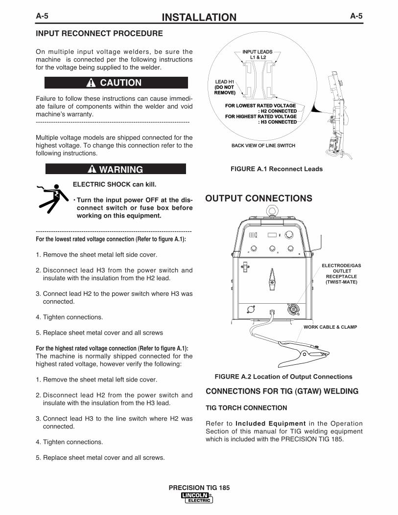
INPUT RECONNECT PROCEDURE
On multiple input voltage welders, be sure themachine is connected per the following instructionsfor the voltage being supplied to the welder.
Failure to follow these instructions can cause immedi-ate failure of components within the welder and voidmachineʼs warranty.-----------------------------------------------------------------------
Multiple voltage models are shipped connected for thehighest voltage. To change this connection refer to thefollowing instructions.
ELECTRIC SHOCK can kill.
• Turn the input power OFF at the dis-
connect switch or fuse box before
working on this equipment.
------------------------------------------------------------------------For the lowest rated voltage connection (Refer to figure A.1):
1. Remove the sheet metal left side cover.
2. Disconnect lead H3 from the power switch andinsulate with the insulation from the H2 lead.
3. Connect lead H2 to the power switch where H3 wasconnected.
4. Tighten connections.
5. Replace sheet metal cover and all screws
For the highest rated voltage connection (Refer to figure A.1):
The machine is normally shipped connected for thehighest rated voltage, however verify the following:
1. Remove the sheet metal left side cover.
2. Disconnect lead H2 from the power switch andinsulate with the insulation from the H3 lead.
3. Connect lead H3 to the line switch where H2 wasconnected.
4. Tighten connections.
5. Replace sheet metal cover and all screws.
CONNECTIONS FOR TIG (GTAW) WELDING
TIG TORCH CONNECTION
Refer to Included Equipment in the OperationSection of this manual for TIG welding equipmentwhich is included with the PRECISION TIG 185.
CAUTION
WARNING FIGURE A.1 Reconnect Leads
INPUT LEADS INPUT LEADSL1 & L2L1 & L2
LEAD H1LEAD H1(DO NOT (DO NOTREMOVE)REMOVE)
FOR LOWEST RATED VOLTAGEFOR LOWEST RATED VOLTAGE : H2 CONNECTED: H2 CONNECTEDFOR HIGHEST RATED VOLTAGEFOR HIGHEST RATED VOLTAGE : H3 CONNECTED: H3 CONNECTED
BACK VIEW OF LINE SWITCHBACK VIEW OF LINE SWITCH
OUTPUT CONNECTIONS
FIGURE A.2 Location of Output Connections
ELECTRODE/GASOUTLET
RECEPTACLE(TWIST-MATE)
WORK CABLE & CLAMP

A-6INSTALLATION
PRECISION TIG 185
A-6
A PTA-17 Twist-Mate TIG welding torch with cableand connector is supplied with the Ready-Pak Modelsand available for other models (See AccessoriesSection). Turn the Power Switch “OFF”. Connect thetorch cable Twist-Mate quick connect plug into theElectrode/Gas Output Receptacle on the front of thewelder and turn it clockwise until it is tight. This is aTwist-Mate quick connect terminal and also providesthe gas connection for the shielding gas to the torch.
To avoid receiving a high frequency shock, keep
the TIG torch and cables in good condition.
------------------------------------------------------------------------WORK CABLE CONNECTION
A work cable with attached work clamp is factory con-nected to the PRECISION TIG 185. To minimize highfrequency interference, refer to Machine Grounding
and High Frequency Interference Protection sec-tion of this manual for the proper procedure ongrounding the work clamp and work piece.
SHIELDING GAS CONNECTION
An adjustable gas pressure regulator with flow gageand hose is supplied with the PRECISION TIG 185Ready-Pak Models and available separately for othermodels (See Accessories Section). Obtain the neces-sary inert shielding gas (usually argon). Connect thecylinder of gas with the pressure regulator and flowgage. Install the gas hose between the regulator andgas inlet (located on the rear of the welder). The gasinlet has a 5/16-18 right hand female thread;CGA#032.
The availiable Under-Storage Cart features a low plat-form that simplifies loading and unloading of gas cylin-ders.
CYLINDER could explode
if damaged.
• Keep cylinder upright and chained
to a support.
• Keep cylinder away from areas
where it could be damaged.
• Never allow the torch to touch the cylinder.
• Keep cylinder away from live electrical circuits.
• Maximum inlet pressure 150 psi.
------------------------------------------------------------------------
A cylinder is loaded by leaning it slightly sideways androcking it up on the platform, being careful not toallow the Under-Storage Cart to roll. Secure the
cylinder in place with the provided chain. Unloadby following these steps in reverse.
REMOTE CONTROL CONNECTION
A remote control receptacle is provided on the casefront of the welder for connecting a remote control toto the machine. A Foot Amptrol™, foot activatedremote control, is included with the PRECISION TIG185 Ready-Pak models and availiable separately forother models. Refer to the Optional Accessories sec-tion of this manual for other available remote controls.
CONNECTIONS FOR STICK (SMAW)
WELDING
STICK ELECTRODE CABLE AND WORK CABLE
CONNECTION
Refer to Field Installed Options in Accessories Sectionof this manual for STICK welding equipment which isavailiable for use with the PRECISION TIG 185. Anelectrode holder with Twist-Mate cable and Twist-Mate connector are availiable separately for use withthe PRECISION TIG 185. (See Accessories Section).Turn the Power Switch “OFF”. Connect the Twist-Mate quick connect plug into the Electrode/GasOutput Receptacle and turn it clockwise until it is tight.The work cable and work clamp are factory connect-ed.
WARNING
WARNING

B-1OPERATION
PRECISION TIG 185
B-1
ELECTRIC SHOCK
can kill.• Do not touch electrically live parts
or electrode with skin or wet cloth-
ing.
• Insulate yourself from work and
ground.
• Always wear dry insulating gloves.
• Read and follow “Electric Shock Warnings” in the
Safety section if welding must be performed under
electrically hazardous conditions such as welding in
wet areas or on or in the workpiece.
--------------------------------------------------------------------------------
FUMES AND GASES
can be dangerous.
• Keep your head out of fumes.
• Use ventilation or exhaust at the
arc, or both, to remove fumes and
gases from breathing zone and
general area.
------------------------------------------------------------------------
WELDING SPARKS can cause fire or
explosion
• Keep flammable material away.
• Do not weld on containers that
have held combustibles.
------------------------------------------------------------------------
ARC RAYS can burn.
• Wear eye, ear and body
protection.
------------------------------------------------------------------------
SAFETY PRECAUTIONS
Read and understand this entire section before oper-ating the machine.
Observe additional Safety Guidelines detailed in
the beginning of this manual.
------------------------------------------------------------------------
WARNING
INPUT POWER
POSITIVE OUTPUT
NEGATIVE OUTPUT
DIRECT CURRENT
PROTECTIVEGROUND
WARNING ORCAUTION
DO NOT SWITCHWHILE WELDING
GRAPHIC SYMBOLS THAT APPEAR ONTHIS MACHINE OR IN THIS MANUAL

B-2OPERATIONB-2
PRODUCT DESCRIPTION
The PRECISION TIG 185 is a member of our fieldacclaimed Precision TIG family of industrial arc weld -ing power sources. Premium features include:
1. Precise constant current output.2. Full range square wave AC/DC TIG (GTAW) weld--
ing. 3. Enhanced version of the patented Micro-
Start™Technology for its lower Minimum(5 amps)to higher Maximum (185 amps) output controlrange.
4. Built-in high frequency stabilization for DC TIGstarting and continuous AC TIG welding.
5. AC/DC Stick (SMAW capability.) A new undercar-riage (with gas bottle rack) is available for fieldinstallation, or is included with an available Ready-Pak TIG Welding Package. The Precision TIGpatented convenient built-in storage provisions forwelding components and cable management.
The PRECISION TIG 185 also provides advancedfeatures such as: • Digital Meter• Presettable control, adjustable Auto Balance™• Fan As Needed (F.A.N.) • Timers for fixed Preflow and variable Postflow
shielding gas. • Built-in, easy to set single knob Pulse TIG control
with a "blinking" light to indicate the pulse frequencysetting.
• Auto-Sense remote control selection.• Tool-less Twist-Mate electrode cable connection. • Built-in work clamp cable permanently attached.
Four models are available for 60Hz. with Domesticand Canadian input voltages, as well as anInternational model with 50/60Hz voltages.
RECOMMENDED PROCESSES AND
EQUIPMENT
RECOMMENDED PROCESSES
The PRECISION TIG 185 is recommended for theTIG (GTAW) and Stick (SMAW) welding processeswithin its output capacity range of 5 amps DC,or 7amps AC, to 185 amps AC/DC. It is compatible withmost Magnum TIG accessories, as well as manyindustry standard items, such as TIG torches (adaptedfor Twist-Mate), hoses, and water coolers.
PROCESS LIMITATIONS
The PRECISION TIG machines are not recommendedfor arc gouging due to it's limited output capacity, andare also not recommended for pipe thawing.
RECOMMENDED EQUIPMENT/INTERFACE
(See Installed Options in Accessories Section formore details)
The PRECISION TIG 185 will be available as a basicMachine (Only) and in two Factory-ConfiguredWelding Packages:
1. Machine(Only) (K2345-1)
2. Ready-Pak (K2347-1)
3. Ready-Pak w/Cart (K2347-2)
Basic module will also be available as with Domestic,Canadian and International input voltages for userconfiguration, with optional accessories. Select Machine 208/230/1/60 Machine with 6 NEMA 6-50P
Plug Cable and Receptacle (K2345-1)
460/575/1/60 Machine only with cable (K2345-2)
380/400/415/1/50/60 Machine onlywith cable (K2346-1)
Torch Starter Kit Air Cooled System: Water Cooled System:(Select one) TIG-Mate TIG-Mate 20
Torch Starter Kit* Torch Starter Kit*Water Cooler Not Applicable 115V 50/60Hz
Cool-Arc 40*Under-Storage K2348-(*)Cart (Optional )Optional Remote Arc Start Switch*Trigger Device Foot Amptrol*(Select one) Start Pedal Foot Amptrol*
Hand Amptrol**For “Part Numbers” or “K Numbers” see Accessories Section.
EQUIPMENT LIMITATIONS
The PRECISION TIG machines are protected fromover loads beyond the output ratings and duty cycles,per the Specifications in the Installation Section, withThermostat protection of the output power coils andrectifiers.
The PRECISION TIG 185 machine uses Twist-Mateoutput terminals, therefore stud connection adapters(such as LECO. S19257-series) cannot be used fortorch connection.
If a PRECISION Tig 185 is powered from an enginegenerator which doesnʼt have sufficient capacity, theAC Balance control and the Output control will notprovide full range of control.
WELDING CAPABILITY(Duty Cycle)
The PRECISION TIG 185 is rated at 185 amps, 27volts, at 15% duty cycle on a ten minute basis. It iscapable of higher duty cycles at lower output currents.See rated output graph, on specification sheet locatedin the Installation Section. If the duty cycle is exceed-ed, a thermal protector will shut off the output until themachine cools.
PRECISION TIG 185

B-3OPERATIONB-3
CONTROL FUNCTIONALITY
1. POWER SWITCH – Input line switch turns inputpower ON or OFF, as indicated by the on or off sta-tus of the front panel digital display (See Item 6).
2. POLARITY SWITCH – The rotary power switch has3-positions for DC+, AC and DC- selections for theelectrode output stud welding polarity.
• Do not switch the polarity switch
while welding or damage may result
to the machine.
------------------------------------------------------------------------3. MODE SWITCH – The push button switch allows
selection of the two machine welding modes asindicated by colored mode lights: • STICK mode – Top position Red light.• TIG mode – Bottom position Green light.
4. AC BALANCE CONTROL – The AC BalanceControl permits adjustment of the AC TIG wave bal-ance adjustment from Max. Penetration (80% nega-tive wave) at full CW rotation setting, to Max.Cleaning (60% positive wave) at CCW rotation, andincludes:
• Auto Balance position indicated by the Green panellight turning on.
This setting position feature automatically provides theproper amount of cleaning and penetration for normalAC TIG welding.
5. MAXIMUM OUTPUT CONTROL – Presets the out-put welding current over the rated output range ofthe machine:• With a Remote Current Control (Amptrol) connect-
ed to the Remote Receptacle (See item 10), thisknob sets the Maximum output current level settable with the remote Amptrol.
• For Pulse TIG (See Item 8) this knob sets thePeak Pulse level, with the Remote Amptrol (ifused).
6. DIGITAL METER – A 3 digit LED meter is used todisplay the preset output current level before weld-ing, and actual output level while welding:• A lit display indicates input power is turned on.
(See Item 1.)
7. POST FLOW TIME – Sets the TIG mode shieldinggas post flow time over the range of about 1 to 30seconds after the arc is shut off.
Note: Gas preflow time is fixed at 0.5 second only inTIG mode, but no preflow time will occur if the arc isrestarted during Post Flow time, since shielding gaswould not have stopped flowing.
PRECISION TIG 185
CONTROLS AND SETTINGSAll operator controls and adjustments are located on the front of the PRECISION TIG 185. Refer to Figure B.1and corresponding explanations.
FIGURE B.1 - CONTROL PANEL
1. POWER SWITCH2. POLARITY SWITCH3. MODE SWITCH4. AC BALANCE CONTROL5. MAXIMUM OUTPUT CONTROL (AMPS)6. DIGITAL METERS7. POST FLOW TIME8. PULSE TIG CONTROL9. THERMAL SHUTDOWN LIGHT10. REMOTE RECEPTACLE11. ELECTRODE/GAS OUTPUT
RECEPTACLE12. WORK CABLE13. REMOVABLE LIFT EYEBOLT
513
2
6
3
4
1
7
9
10
11
12
8
CAUTION

B-4OPERATIONB-4
8. PULSE TIG CONTROL – The Pulse TIG featurebuilt into the Precision TIG 185 is simplified to be asingle knob control which sets the Pulse Frequencyover the peak pulses/sec. range of about 0.1 to 20pulses per second:• Full CCW (min.) setting of the control knob shuts
off Pulse TIG (0.0 pps).• Peak Pulse level is set by the Max. Output Control
and the Remote Amptrol (if used).• Background Current level is typically optimized at
a fixed 50% of Peak Pulse level setting.• Peak Pulse % On-time is typically optimized at a
fixed50%.A Green light "blinks" with each Peak Pulse to indi-cate the Pulse TIG Control setting before and dur-ing welding.
9. OVER TEMPERATURE LIGHT - If the welderoverheats due to blocked air flow, high ambient airtemperature, or exceeded duty cycle, an internalthermostat will open disabling the welding outputand this yellow light will illuminate. The cooling fanswill continue to run to cool the unit during this time.The light will go out when the unit cools and thethermostat resets. Once the light goes out, themachine will again become available to weld.
10. REMOTE RECEPTACLE – Provides for connec-tion of remote control and/or arc start switch onlyin TIG Mode: ( There is no remote output controlcapability when stick welding.• Plugging a remote current control (Amptrol) into
this receptacle automatically switches the outputcontrol from the panel Max Output Control (SeeItem 5) to the remote control.
• The connected remote control will then controlthe output current between the Min. range of themachine and the setting of the panel Max OutputControl.
• Switching Mode Switch (See Item 3) to Stick willautomatically disable the connected remote con-trol and switch the output control back to the MaxOutput panel control.
11. ELECTRODE/GAS OUTPUT RECEPTACLE -
This quick connect Twist-Mate receptacle provideselectrical connection to the electrode holder andcable for Stick welding and a combined electricaland gas connection for the TIG torch when TIGwelding.
12. WORK CABLE - This work cable is factory con-nected to the welder and is connected to the workpiece to complete the welding circuit. Refer toMachine Grounding and High Frequency
Interference Protection in the Installation sectionof this manual for the proper procedure on ground-ing the work clamp and work piece to minimizehigh frequency interference.
OPERATING STEPS
WELDING IN TIG MODE
1. Connect the TIG torch and cable Twist-Mate quickconnect plug to the Electrode/Gas output recepta-cle. This receptacle also contains an integral gasconnection for the torch. Connect the work clamp tothe work piece.
2. Set the TIG/STICK switch to “TIG”.
3. Set the Polarity Switch to DC- for welding steel orstainless steel; or to AC for welding aluminum.
4. Connect the Foot Amptrol to the Remote ControlConnector.
5. Turn on the cylinder gas valve and adjust the flowregulator to obtain desired flow.
6. Turn the power switch to “ON”. NOTE: There will bea 15 second gas flow when the power is turned on.
7. Preset the Output Control on the control panel tothe maximum desired amps, as read on the digitalmeter.
8. Depress the Foot Amptrol to energize the torch andestablish an an arc with the work piece. The digitalmeter reads the actual amps while welding.
NOTE: When the TIG/STICK switch is set to “TIG”,depressing the remote control will start a 0.5 secondgas pre-flow before energizing the TIG torch. Whenthe remote control is released the TIG torch is de-energized and gas flow will continue for the time setby the Post Flow Time control. When the polarityswitch is set to DC, the TIG Arc Starter will turn onand off automatically to start and stabilize the arc. InAC the TIG Arc Starter will turn on with the output andremain on continuously until the remote control isreleased.
PULSE TIG CONTROL
Use this knob to set the frequency or the number ofpulses per second(pps), from 0.1pps to 20pps.
• This setting adjusts heat output and bead shape fortravel speed. Thinner plate that is welded with fastertravel speed will require higher frequency than thick-er plate with slower travel speed. 2-3pps is a typicalstarting point.
PRECISION TIG 185

B-5OPERATIONB-5
REMOTE CONTROL OPERATION
A Foot Amptrol ™is included with the PRECISIONTIG 185 Ready-Pak models and availiable for othermodels (See Accessories Section) for remote currentcontrol while TIG welding. An optional Hand Amptrolmay also be used. An optional Arc Start Switch maybe used to start and stop the welding if no remotecontrol of the current is desired. Refer to theAccessories Section of this manual.
Both the Hand and Foot Amptrol work in a similarmanner. For simplicity, the following explanation willrefer only to “Amptrols”, meaning both Foot and Handmodels. The term “minimum” refers to a foot pedal inthe “up” position, as it would be with no foot pressure,or a Hand Amptrol in the relaxed position, with nothumb pressure.
“Maximum” refers to a fully depressed Foot Amptrol,ora fully extended Hand Amptrol.
When the welder is in TIG modes activating theAmptrol energizes the electrode terminal and variesthe output welding current from its minimum value of 5Amp (DC) or 7 Amp (AC), to the maximum value setby the Current Control on the control panel. This helpseliminate accidental high current damage to the workpiece and/or tungsten, and provides a fine control ofthe current. When the welder is in the stick mode aremote control has no effect and is not used.
It is important to note that, in some cases, the tung-sten will not start an arc at the minimum currentbecause the tungsten may be too large or cold. Tostart an arc reliably, it is important to depress theAmptrol far enough so that the machine output currentis near the tungsten operating range. For example, a3/32” tungsten may be used on DC- to weld over thefull range of the machine.
To start the arc, the operator may have to turn the cur-rent control up and depress the Amptrol approximately1/4 of the way down. Depressing the Amptrol to itsminimum position may not start the arc. Also if thecurrent control is set too low, the arc may not start. Inmost cases, a large or cold tungsten will not readilyestablish an arc at low currents. This is normal. InDirect Current mode the PRECISION TIG 185 willstart a 3/32”, 2% thoriated tungsten electrode at 15amperes provided the electrode tip is properly ground-ed and not contaminated.
BENEFITS OF THE PRECISION TIG 185 DESIGN
In AC TIG welding of aluminum, the positive portion ofthe AC wave provides cleaning (removal of aluminumoxide) of the work piece. This is desirable on materialswith a heavy oxide coating. However the positive por-tion may also cause the electrode to overheat at highcurrents causing “tungsten spitting”. The negative por-tion of the AC wave offers no cleaning action but con-centrates more heat on the work.
The AC waveform of the PRECISION TIG 185 opti-mizes cleaning and heating of the work. The result isthe capability to weld through the complete range inAC TIG or DC- TIG requiring only one electrode, a3/32” 2% thoriated tungsten.
PRECISION TIG 185

B-6OPERATIONB-6
WELDING IN STICK MODE
1. Put the electrode holder and cable quick connectplug into the electrode output receptacle. Turnclockwise until tight. Connect the work clamp to thework piece.
2. Set the TIG/STICK switch to “STICK”.
3. Set the Polarity Switch to the weld mode desired forthe type of electrode being used (most commonlyDC+).
4. Place the electrode in the electrode holder.
• In Stick Mode the output terminal
and electrode will be electrically hot
whenever the power switch is
turned on.
-----------------------------------------------------------------------
5. Turn the power switch to “ON”.
6. Adjust the Current Control to the desired amps.
7. Strike an arc and weld.
NOTE: When the TIG/STICK switch is set to “STICK”the output is always on when the power switch is on.A remote control has no effect on the welding currentand the gas flow and high frequency TIG arc starterare disabled.
PRECISION TIG 185
RECOMMENDED ELECTRODE AMPERAGE RANGES - PRECISION TIG 185The PRECISION TIG 185 is rated from 5-185 Amps.
SMAW ProcessWelding Amp Range for Stick Electrode Size
ELECTRODE TYPE POLARITY 3/32" 1/8" 5/32"Fleetweld 5P, Fleetweld 5P+ E6010 DC+ 40 - 70 75 - 130 90 - 175Fleetweld 180 E6011 DC+ 40 - 80 55 - 110 105 - 135Fleetweld 37 E6013 DC+ 70 - 95 100 - 135 145 - 180Fleetweld 47 E7014 DC- 75 - 95 100 - 145 135 - 200Excalibur E7018 DC+ 85 - 110 110 - 160 130 - 200Blue Max Stainless DC+ 40 - 80 75 - 110 95 - 150Red Baron Stainless DC+ 40 - 70 60 - 100 90 - 140Mild steel procedures are based on recommended procedures listed in C2.10 8/94 and the maximum rating of the PRECISION TIG 185Blue Max procedures are based on C6.1 6/95Red Baron Procedure are based on ES-503 10/93
GTAW ProcessElectrode Polarity DC- AC Approximate Argon
Electrode Tip Preparation Sharpened Balled Gas Flow Rate
Electrode Type EWZr C.F.H. (l/min.)EWTh-1, EWCe-2 EWTh-1, EWTh-2EWTh-2, EWLa-1 EWP EWCe-2, EWLa-1 Stainless
Tungsten Size (in.) EWG EWG Aluminum Steel.010 Up to 15 A. Up to 10 A. Up to 15 A. 3-8 (2-4) 3-8 (2-4).020 Up to 15 A. Up to 15 A. Up to 20 A. 5-10 (3-5) 5-10 (3-5).040 Up to 80 A. Up to 40 A. Up to 60 A. 5-10 (3-5) 5-10 (3-5)1/16 Up to 150 A. Up to 100 A. Up to 130 A. 5-10 (3-5) 9-13 (4-6)3/32 Up to MAX. A. Up to 160 A. Up to MAX. A. 13-17 (6-8) 11-15 (5-7)1/8 X Up to MAX. A. X 15-23 (7-11) 11-15 (5-7)
Tungsten electrodes are classified as follows by the American Welding Society (AWS):Pure ..................................EWP........green TRI-MIX OF ELEMENTS.............EWG.........gray+1% Thoria .......................EWTh-1...yellow+2% Thoria .......................EWTh-2...red+2% Ceria.........................EWCe-2...orange+1.5% Lanthana ...............EWLa-1 ...black+0.15 to 0.40% Zirconia....EWZr.......brown
Ceriated Tungsten is now widely accepted as a substitute for 2% Thoriated Tungsten in AC and DC applications.
WARNING

C-1ACCESSORIESC-1
FACTORY INSTALLED OPTIONS
The PRECISION TIG 185 will be available in twoFactory-Configured Welding Packages:
1. Precision TIG 185 Ready-Pak (K2347-1)
• 208/230/1/60 Machine (K2345-1)• 9 ft. (2.7m) Input Cable with NEMA 6-50P Plug*• NEMA 6-50R Receptacle• Integrated 10 ft.(3.1m)Work Lead w/Clamp*• Gas Regulator with 10 ft.(3.1m). Hose• PTA-17 12.5”(318mm) Ultra=Flex Torch with
3/32”(2.4mm)Electrode and Parts• Foot Amptrol (K870)• TIG Slide Rule ( WC332)*• GTAW Book (JFLF-834)*• Lift Eyebolt*
The PRECISION TIG 185 will also be available asBasic models with Domestic input voltages for user-configuration with optional accessories: (See TableC.1)
2. PRECISION TIG 185 Ready-Pak w/Cart (K2347-2)
• 208/230/1/60 Machine (K2345-1)• 9 ft.(2.7m) Input Cable with NEMA 6-50P Plug*• NEMA 6-50R Receptacle• Integrated 10 ft.(3.1m) Work Lead w/Clamp*• Gas Regulator with 10 ft.(3.1m) Hose• PTA-17 12.5 ft.(3.8m) One cable Superflex Torch
with 3/32”(2.4mm) Electrode and Parts• Foot Amptrol (K870)• TIG Slide Rule (WC332)*• GTAW Book (JFLF-834)*• Lift Eyebolt*• Under-Storage Cart (K2348-1)
* Included with K2345-1 Machine Only model.
PRECISION TIG 185
Water Cooled System
K2267-1 TIG-Mate 20 Torch Starter KitIncludes:• 200A PTW-20 12.5 ft.(3.81m) Torch • KP510 Parts Kit• Regulator & Hose• K1622-4 Twist Mate Torch Adapter• Water Hose & Hose Coupler• Work Cable & Clamp (Not required for
Precision TIG 185)
K1813-1 115V 50/60Hz Cool-Arc 40
Select Machine
OptionalTorch Starter Kit(Select one)
Water Cooler
Optional Under-Storage Cart
Optional Remote Trigger Device(Select one)
208/230/1/60 Machine with 9 ft.(2.7m) NEMA 6-50P Plug Cable and Receptacle (K2345-1)
460/575/1/60 Machine only with Cable (K2345-2)
380/400-415/1/50-60 Machine only with Cable (K2346-1)
Air Cooled System
K2266-1 TIG-Mate Torch Starter Kit Includes:• 150A PTA-17 12.5 ft.(3.81m) Torch. • KP508 Parts Kit.• Regulator & Hose.• K1622-1 Twist Mate Torch Adapter.• Work Cable & Clamp (Not required for Precision
TIG 185)
Not Applicable
TABLE C.1
K2348-1
K814 Arc Start SwitchK870 Foot AmptrolK870-1 Start Pedal Foot AmptrolK963-3 Hand Amptrol

C-2ACCESSORIESC-2
FIELD INSTALLED OPTIONS
The following Options/Accessories are available forthe PRECISION TIG 185:
• K2348-1 Under-Storage Cart Includes a front magnetic latch storage drawer andrear storage bin on a single bottle undercarriage.(L12225 Installation Instructions included)
• K870 Foot Amptrol
Single pedal foot activation of arc start switch andoutput control, with 25 ft.(7.6m) plug cable.
• K870-1 Start Pedal Foot Amptrol
Independent start pedal on control pedal providestwo-stage foot action to easily feel start switch clo-sure at minimum output level for enhanced arc startand crater-fill control. Provided with adjustable, orremovable , heel stop and 25 ft.(7.6m) plug cable.
• K963-3 Hand Amptrol
Fastens to torch for convenient thumb activation ofarc start switch and output control, with 25 ft.(7.6m)plug cable:
• K814 Arc Start Switch
Needed for TIG welding without an Amptrol.Includes 25 ft.(7.6m) plug cable, and attaches totorch for convenient finger control.
• TIG-Mate Torch Starter Kits:
Includes Torch with Twist-Mate adapter and acces-sories listed below:
K2266-1 TIG-Mate Torch Starter Kit Includes:• 150A PTA-17 12.5 ft.(3.8m) Torch • KP508 Parts Kit• Regulator & Hose• K1622-1 Twist Mate Torch Adapter• Work Cable & Clamp (Not required for PRECISION
TIG 185)
K2267-1 TIG-Mate 20 Torch Starter Kit Includes:• 200A PTW-20 12.5 ft.(3.8m) Torch • KP510 Parts Kit• Regulator & Hose• K1622-4 Twist Mate Torch Adapter• Water Hose & Hose Coupler • Work Cable & Clamp (Not required for PRECISION TIG 185)
• Magnum “Pro-Torch™ TIG Torch” assemblies andAccessories. Requires Twist-Mate Adapter:
K1622-1 for PTA-9/-17 K1622-3 for PTA-26K1622-4 for PTW water cooled torch
• Harris #3100211 Harris Argon Flow Regulator
(Includes 10 ft.(3.1m) hose.)
• K2374-1 Electrode Holder and Cable
200 amp Electrode Holder with 10 ft.(3.1m) cableand Twist-Mate connector.
PRECISION TIG 185

D-1MAINTENANCED-1
SAFETY PRECAUTIONS
ELECTRIC SHOCK can kill.
• Only qualified personnel should per-
form this maintenance.
• Turn the input power OFF at the dis-
connect switch or fuse box before
working on this equipment.
• Do not touch electrically hot parts.
------------------------------------------------------------------------
To avoid receiving a high frequency shock, keep
the TIG torch and cables in good condition.
------------------------------------------------------------------------
ROUTINE AND PERIODIC MAINTENANCE
1. Disconnect power supply lines to machine beforeperforming periodic maintenance.
2. Periodically clean the inside of the machine with alow pressure air system. Be sure to clean the fol-lowing components thoroughly.
• Main Transformer• Electrode/Gas Output Receptacle • Polarity Switch• Rectifier Assembly• Arc Starter/Spark Gap Assembly• PC Boards• Fan Blades
3. Inspect welder output and control cables for fraying,cuts, and bare spots.
4. Keep TIG torch and cables in good condition.
5. Clean air louvers to ensure proper air flow and cool-ing.
6. The fan motor has sealed ball bearings whichrequire no maintenance.
7. SPARK GAP ADJUSTMENT
The spark gap .020(.5mm) is set at the factory to agap of 0.015 inches (0.4mm) See Figure D.1. Thissetting is adequate for most applications. Whereless high frequency is desired, the setting can bereduced to 0.015 inches (0.4mm).
Use extreme caution when working with circuit of
the high frequency. The high voltages developed
can be lethal. Turn the input power off using the
disconnect switch or fuse box before working
inside machine. This is particularly important
when working on the secondary circuit of the high
voltage transformer (T3) because the output volt-
age is dangerously high.
-----------------------------------------------------------------------Refer to figure D.1. Note in highly dirty environmentswhere there is an abundance of conductive contami-nants, use a low pressure air stream or a firm piece ofpaper to clean the spark gap. Do not disturb the facto-ry setting.
To check the spark gap:- Turn off input power as specified above.- Remove the right side panel from the
machine, the spark gap box is located on thelower right side.
- Check the spark gap with a feeler gauge.If adjustment is needed:
- Adjust the gap by loosening the allen headscrew in one of the aluminum blocks, nearthe front of the unit and tighten the screw inthe new position.
If the gap is correct:- Replace the wraparound.
8. Inspect gas hose and inlet fitting for cracks or leaks.
9. Replace any unreadable labels or decals.
10. Verify that the machine and welding circuit is prop-erly grounded.
FIGURE D.1 SPARK GAP
FAN MOTOR OR FAN BLADE REPLACEMENT
When installing a new fan blade or fan motor be sureto maintain proper shaft spacing per Figure D.2 below.
PRECISION TIG 185
WARNING
WARNING
WARNING
.020 Spark Gap.020 Spark Gap
FIGURE D.2 .30

E-1TROUBLESHOOTINGE-1
PRECISION TIG 185
If for any reason you do not understand the test procedures or are unable to perform the tests/repairs safely, contact your
CAUTION
This Troubleshooting Guide is provided to help youlocate and repair possible machine malfunctions.Simply follow the three-step procedure listed below.
Step 1. LOCATE PROBLEM (SYMPTOM).
Look under the column labeled “PROBLEM (SYMP-TOMS)”. This column describes possible symptomsthat the machine may exhibit. Find the listing thatbest describes the symptom that the machine isexhibiting.
Step 2. POSSIBLE CAUSE.
The second column labeled “POSSIBLE CAUSE” liststhe obvious external possibilities that may contributeto the machine symptom.
Step 3. RECOMMENDED COURSE OF ACTION
This column provides a course of action for thePossible Cause, generally it states to contact yourlocal Lincoln Authorized Field Service Facility.
If you do not understand or are unable to perform theRecommended Course of Action safely, contact yourlocal Lincoln Authorized Field Service Facility.
HOW TO USE TROUBLESHOOTING GUIDE
Service and Repair should only be performed by Lincoln Electric Factory Trained Personnel.Unauthorized repairs performed on this equipment may result in danger to the technician andmachine operator and will invalidate your factory warranty. For your safety and to avoid ElectricalShock, please observe all safety notes and precautions detailed throughout this manual.
__________________________________________________________________________
WARNING

E-2TROUBLESHOOTINGE-2
PRECISION TIG 185
Observe all Safety Guidelines detailed throughout this manual
If for any reason you do not understand the test procedures or are unable to perform the tests/repairs safely, contact your
CAUTION
PROBLEMS
(SYMPTOMS)
POSSIBLE
CAUSE
RECOMMENDED
COURSE OF ACTION
Machine is Dead -No Output - NoFan
Fan runs normally at power up - Nooutput from machine in either Stickor TIG modes.
Fan runs - No output from machinein either Stick or TIG modes and theyellow light on the control panel ison.
Machine does not respond (no gasflow, no high frequency and no opencircuit voltage) when arc start switchor Amptrol is activated - fan is work-ing.
1. Make certain that the input powerswitch is in the “ON” position andmachine is plugged in.
2. Check the input voltage at themachine. Input voltage mustmatch the rating plate and volt-age connection. Refer toReconnect Procedure in theInstallation section of this manual.
3. Blown or missing fuses in inputline.
1. Check for proper input voltagesper nameplate and voltage recon-nection.
2. Check to make sure polarityswitch is not in between two posi-tions.
1. Welding application may haveexceed the recommended dutycycle. Allow the unit to run untilthe fan cools the unit and the yel-low light goes out.
1. Machine MUST be in the TIGMode.
2. The Amptrol may be defective.Check for continuity between pins“D” and “E” on cable connectorwhen Amptrol is depressed.
If all recommended possible areasof misadjustment have beenchecked and the problem persists,Contact your local Lincoln
Authorized Field Service Facility.
OUTPUT PROBLEMS

E-3TROUBLESHOOTINGE-3
PRECISION TIG 185
Observe all Safety Guidelines detailed throughout this manual
If for any reason you do not understand the test procedures or are unable to perform the tests/repairs safely, contact your
CAUTION
PROBLEMS
(SYMPTOMS)
POSSIBLE
CAUSE
RECOMMENDED
COURSE OF ACTION
Machine regularly over heats - the-mostat opens, Yellow light on frontpanel glows. The fan runs butmachine has no output.
Output current reduced significantlywhen AC Balance control knob is setnear or at max. penetration or whenOutput control is set near or at fulloutput.
1. Welding application may exceedrecommended duty cycle. Reducethe duty cycle.
2. Dirt and dust may have cloggedthe cooling channels inside themachine. Blow out unit with clean,dry low pressure air.
3. Air vents and exhaust louvers maybe blocked due to inadequateclearance around machine.
1. Input power to machine doesnʼthave sufficient capacity. Trychanging Input power to a suffi-cient supply, refer to Installationsection.
2. Machine is powered from anengine generator or an enginewelder. If welding at high currentsare needed, try powering machinefrom electricity grid instead ofengine generator.
3. Set AC Balance control at AutoBalance position.
If all recommended possible areas ofmisadjustment have been checkedand the problem persists, Contact
your local Lincoln Authorized
Field Service Facility.
OUTPUT PROBLEMS

E-4TROUBLESHOOTINGE-4
PRECISION TIG 185
Observe all Safety Guidelines detailed throughout this manual
If for any reason you do not understand the test procedures or are unable to perform the tests/repairs safely, contact your
CAUTION
PROBLEMS
(SYMPTOMS)
POSSIBLE
CAUSE
RECOMMENDED
COURSE OF ACTION
Machine output is intermittently lost.Gas flow and high frequency arealso interrupted.
Arc “Flutters” when TIG welding.
Arc “Pulsates” when AC TIG weld-ing.
1. Problem may be caused by highfrequency interference. Make surethat the machine is groundedproperly according to the installa-tion instructions. If there are otherhigh frequency sources in thearea, make certain that they aregrounded properly.
2. Check Amptrol for proper opera-tion and loose connections.
3. Check for proper input voltageand proper voltage reconnection.
1. Tungsten electrode may be toolarge in diameter for the currentsetting.
2. Tungsten not “sharp” when weld-ing in DC - mode.
3. Gas shielding may be insufficient.Increase gas flow; reduce tung-sten stickout beyond gas cup.
4. Check for contaminated gas orleaks in the gas line, torch, or con-nections.
5. If a helium blend is used as ashielding gas, then reduce thepercentage of helium.
1. Micro Switch mounted on PolaritySwitch is not opening in “AC”mode.
If all recommended possible areas ofmisadjustment have been checkedand the problem persists, Contact
your local Lincoln Authorized
Field Service Facility.
TIG MODE PROBLEMS

E-5TROUBLESHOOTINGE-5
PRECISION TIG 185
Observe all Safety Guidelines detailed throughout this manual
If for any reason you do not understand the test procedures or are unable to perform the tests/repairs safely, contact your
CAUTION
PROBLEMS
(SYMPTOMS)
POSSIBLE
CAUSE
RECOMMENDED
COURSE OF ACTION
Black areas along weld bead.
Weak high frequency - machine hasnormal welding output.
High frequency “spark” is present attungsten electrode, but operator isunable to establish a welding arc.Machine has normal open circuitvoltage (refer to Technical
Specifications in the InstallationChapter).
1. Clean any oily or organic contam-ination from the work piece.
2. Tungsten electrode may be cont-aminated. Replace or sharpen.
3. Check for contaminated gas orleaks in the gas line, torch, orconnections.
4. Gas shielding may be insufficient.Increase gas flow; reduce tung-sten stickout beyond gas cup.
1. Check for poor connections in thewelding circuit.
2. Gas shielding may be insufficient.Increase gas flow; reduce tung-sten stickout beyond gas cup.
3. Check for work and electrodecables in poor condition allowinghigh frequency to “Leak Off”.
4. Keep cables as short as possible.
5. Check Spark Gap operation andsetting (0.020”).
1. The tungsten electrode may becontaminated. Replace or sharp-en.
2. The current control may be settoo low.
3. The tungsten electrode may betoo large for the process.
4. If a helium blend is used as ashielding gas, then reduce thepercentage of helium.
If all recommended possible areas ofmisadjustment have been checkedand the problem persists, Contact
your local Lincoln Authorized
Field Service Facility.
TIG MODE PROBLEMS

E-6TROUBLESHOOTINGE-6
PRECISION TIG 185
Observe all Safety Guidelines detailed throughout this manual
If for any reason you do not understand the test procedures or are unable to perform the tests/repairs safely, contact your
CAUTION
PROBLEMS
(SYMPTOMS)
POSSIBLE
CAUSE
RECOMMENDED
COURSE OF ACTION
No high frequency. Machine is in theTIG Mode and has normal output.
No gas flow when Amptrol is activat-ed in the TIG Mode. Machine hasoutput - fan runs. A “Click” can beheard indicating that the gas sole-noid valve is operating.
When AC TIG welding, the arc iserratic and there is a loss of “clean-ing” of the work piece.
The end of the tungsten electrodemelts away.
1. If the machine location is in ahighly dirty environment with con-ductive contaminants, check andclean the spark gap with a lowpressure air stream per the main-tenance instructions.
1. Gas supply is empty or not turnedon.
2. Flow regulator may be set toolow.
3. Gas hose may be pinched.
4. Gas flow may be blocked withdirt. Check filter screen inside gasinlet fitting to solenoid valve. Usefilters to prevent reoccurrence.
5. Consult your local welder/gas dis-tributor.
1. Tungsten electrode may be toosmall for process. Use a largerdiameter tungsten or a pure tung-sten.
2. If a helium blend is used as ashielding gas, then reduce thepercentage of helium.
1. The welding current is too highfor the electrode type and/or size.See Electrode Amperage Rangesin the Operation Section of thismanual.
If all recommended possible areas ofmisadjustment have been checkedand the problem persists, Contact
your local Lincoln Authorized
Field Service Facility.
TIG WELDING PROBLEMS

E-7TROUBLESHOOTINGE-7
PRECISION TIG 185
Observe all Safety Guidelines detailed throughout this manual
If for any reason you do not understand the test procedures or are unable to perform the tests/repairs safely, contact your
CAUTION
PROBLEMS
(SYMPTOMS)
POSSIBLE
CAUSE
RECOMMENDED
COURSE OF ACTION
Stick electrode “Blasts Off” when arcis struck.
Stick electrode “sticks” in the weldpuddle.
1. Weld current may be set too highfor electrode size. Reduce currentcontrol setting, or use a largerdiameter electrode.
1. The weld current may be set toolow. Increase the current controlsetting or use a smaller diameterelectrode.
If all recommended possible areas ofmisadjustment have been checkedand the problem persists, Contact
your local Lincoln Authorized
Field Service Facility.
STICK WELDING PROBLEMS

F-1DIAGRAMSF-1
PRECISION TIG 185
WIRING DIAGRAM
- PRECISION TIG 1
85
G4549B
SCR4SCR2SCR1
D C BAREAR GANG
L1
ELECTRODE
T3
NCNOMICRO-SWITCH
T2 L2 L3 C3
SCR3
H1
H G 311A312AOPEN CLOSED CLOSED
G4216G3218 G2G1 217220 AC
E F
PC BOARD
CONTROL PC BOARDD1
S2
SV1GAS VALVE
S2A
BYPASS/ STABILIZER
H1 X1 X2
R 222W 221
WORK
R2
ARC STARTER AS'BLY237 C4R3
231 235
J3236A SPARK GAP 284A 285A
AC DC+ DC-A-C, D-E, B-F B-D, C-E, A-F, G-H B-D, A-E, C-F, G-HPOLARITY SWITCH MICRO SWITCH (REAR VIEW, SHOWN IN AC POSITION)
115VAC18VAC18VAC 78VAC T1
POLARITY SWITCH
H3 H2
H3 (HIGH) H2 (LOW)
L4POS
X4 X5X3 X6 X7X8
C2 C1
201 204 209 210 231 232
AUTO BALANCE LED PULSE FREQ LEDAC BALANCE CONTROL PULSE CONTROL POSTFLOW CONTROLSTICK LEDTIG LED DIGITAL DISPLAY THERMAL LED OUTPUT CONTROLMODE SWITCH
B (L1)W (L2) POWER SWITCHS1 G
FAN 115VAC+( ) ( )_
DC115VAC 238239
210 209 201313 314 1234 65 71112
R 222W 2211 2
89 10
RECEPTACLECA BB 10K A-B FEDC AT MINIMUMD REMOTE TM AMPTROLOPTIONALA E REMOTE
J2 J1
A1 J52 3 4 5 6C B D E
216A
240L5
204 236
231A260R4 220A245 R5 218A244
TRIGGER POWER R1284B 285B
285 284AC
X2
FRONT GANG
RGG G Y
220A 218A
231A
J4311 312 245244 216A 240314 S4 CHOKE313SEE RATING PLATE FOR SPECIFIC VOLTAGES
230 or 400-415 or 575 VOLT CONNECTION H1 and H3 (HIGH) TO POW
ER SWITCH.
208 or 380 or 460 VOLT CONNECTION H1 and H2 (LOW) TO POW
ER SWITCH.H3 NOT CONNECTED; IN
SULATE.
H2 NOT CONNECTED; INSULATE.
C1 AND C2 MUST ALWAYS BE CONNECTED
ACROSS TRANSFORMER PRIMARIESVOLTAGE RECON
NECTION
(AS SHOWN & AS SHIPPED FROM FACTORY)
B-BLACKR-RED G-GREENW-WHITELEAD COLORING CODE: CONNECTOR PIN NUMBERS: VIEW OF CONNECTOR ON PC BOARD1237 814 LATCHEXAMPLE: THIS IS PIN 7 OF CONNECTOR J4COMPONENT VALUE UNITS: RESISTORS: CAPACITORS:OHMS/WATTS MFD/VOLTS J4 ELECTRICAL SYMBOLS PER E1
537.
C1,C2BY-PASS CAPACITORS, .0047/250VAC
C3HIGH VOLTAGE CAPACITOR, .0025/10kV
C4PHASE SHIFT CAPACITOR, 15/250VAC
C5,C6BY-PASS CAPACITORS, .22/400VDC
CB1CIRCUIT BREAKER, 10A
D1FREE WHEELING DIODE
L1OUTPUT INDUCTOR (CHOKE)
L2,L3HIGH FREQUENCY INDUCTORS
L4,L5RF TOROID CHOKES
R1,R2HOLDING RESISTORS, 100/100W
R3PHASE SHIFT RESISTOR, 200/100W
R4,R5MICRO START RESISTORS, 12/100W
S1INPUT POWER SWITCH
S2POLARITY SWITCH
S2AMICROSWITCH ON POLARITY SWITCH
S4MAIN CHOKE THERMOSTAT
SCR1,2,3,4MAIN POWER SCR'S
SV1GAS SOLENOID VALVE, 115VAC
T1MAIN TRANSFORMER
T2HIGH VOLTAGE TRANSFORMER
T3HIGH FREQUENCY TRANSFORMER
43 21235 260
G4220 G2G1 216G3 218217 1 23 456 78
DCPOSSHUNT
X1
236232
INPUT PLUG (208V/230V ONLY)TO GROUND PER NATIONAL ELECTRIC CODE
285 284
G4G212 3 4 G3 G1P7 J7
1 2 3J6 4
CONNECT GREEN LEAD TO GROUND PER
NATIONAL AND LOCAL ELECTRICAL CODE
CONNECT BLACK AND WHITE LEADS
TO SUPPLY CIRCUITB (L1) W (L2)G380V AND ABOVE 208V/230V ONLY
311312
WIR
ING
DIA
GR
AM
- P
RE
CIS
ION
TIG
185
G4549
B
SC
R4
SC
R2
SC
R1
D
C
B
A
RE
AR
GA
NG
L1
ELE
CT
RO
DE
T3
NC
NO
MIC
RO
-SW
ITC
H
T2
L2
L3
C3
SC
R3
H1
H
G3
11
A
312
A
OP
EN
CLO
SE
DC
LO
SE
D
G4
21
6
G3
21
8G
2
G1
21
7
22
0
AC
EF
PC
BO
AR
D
CO
NT
RO
L P
C B
OA
RD
D1
S2
SV
1
GA
S V
AL
VE
S2A
BY
PA
SS
/S
TA
BIL
IZE
R
H1
X1
X2
R 2
22
W 2
21
WO
RK
R2
AR
CS
TA
RT
ER
AS
'BL
Y
23
7
C4
R3
23
1
235
J3
236
A
SP
AR
KG
AP
28
4A
285
A
AC
DC
+D
C-
A-C
, D
-E, B
-FB
-D, C
-E, A
-F,
G-H
B-D
, A
-E, C
-F, G
-H
PO
LA
RIT
Y S
WIT
CH
M
ICR
O S
WIT
CH
(RE
AR
VIE
W,
SH
OW
N I
N A
C P
OS
ITIO
N)
11
5V
AC
18V
AC
18
VA
C
78
VA
C
T1
PO
LA
RIT
YS
WIT
CH
H3
H2
H3 (
HIG
H)
H2
(L
OW
)
L4
PO
S
X4
X5
X3
X6
X7
X8
C2
C1
20
1
20
4
20
9
21
0
231
232
AU
TO
BA
LA
NC
EL
ED
PU
LS
EF
RE
QL
ED
AC
BA
LA
NC
EC
ON
TR
OL
PU
LS
EC
ON
TR
OL
PO
ST
FL
OW
CO
NT
RO
L
ST
ICK
LE
DT
IG L
ED
DIG
ITA
LD
ISP
LA
Y
TH
ER
MA
LL
ED
OU
TP
UT
CO
NT
RO
L
MO
DE
SW
ITC
H
B(L
1)
W (L2
)
PO
WE
RS
WIT
CH
S1
G
FA
N
11
5V
AC
+( )
( )_
DC
11
5V
AC
23
823
9
210209
201
313314 1
23
46
57
11
12
R 2
22
W 2
21
1 2
89
10
RE
CE
PT
AC
LE
CA
BB
1
0K
A-B
FEDC
AT
MIN
IMU
M
D
RE
MO
TE
TM
AM
PT
RO
L
OP
TIO
NA
L
A
E
RE
MO
TE
J2
J1
A1
J5
2 3 4 5 6
C B D E
21
6A
24
0
L5
204
236
23
1A
260
R4 2
20
A
245
R5
21
8A
24
4
TR
IGG
ER
PO
WE
R
R1
28
4B
285
B
285
28
4
AC
X2
FR
ON
TG
AN
G
RG
G
G
Y
22
0A
218
A
231
A
J4
311312
245244
216A240
31
4
S4
CH
OK
E
31
3
SE
E R
AT
ING
PL
AT
E F
OR
SP
EC
IFIC
VO
LT
AG
ES
23
0
or
400
-41
5 o
r 5
75 V
OL
T C
ON
NE
CT
ION
H1
an
d H
3 (
HIG
H)
TO
PO
WE
R S
WIT
CH
.
20
8
or
380
o
r 4
60
VO
LT
CO
NN
EC
TIO
N
H1
an
d H
2 (
LO
W)
TO
PO
WE
R S
WIT
CH
.
H3
NO
T C
ON
NE
CT
ED
; I
NS
UL
AT
E.
H2
NO
T C
ON
NE
CT
ED
; I
NS
UL
AT
E.
C1
AN
D C
2 M
US
T A
LW
AY
S B
E C
ON
NE
CT
ED
AC
RO
SS
TR
AN
SF
OR
ME
R P
RIM
AR
IES
VO
LT
AG
E R
EC
ON
NE
CT
ION
(AS
SH
OW
N &
AS
SH
IPP
ED
FR
OM
FA
CT
OR
Y)
B-B
LA
CK
R-R
ED
G-G
RE
EN
W-W
HIT
E
LE
AD
CO
LO
RIN
G C
OD
E:
CO
NN
EC
TO
R P
IN N
UM
BE
RS
:
VIE
W O
F C
ON
NE
CT
OR
ON
PC
BO
AR
D
12
37
81
4
LA
TC
H
EX
AM
PLE
: T
HIS
IS
PIN
7O
F C
ON
NE
CT
OR
J4
CO
MP
ON
EN
T V
AL
UE
UN
ITS
:R
ES
IST
OR
S:
CA
PA
CIT
OR
S:
OH
MS
/WA
TT
S
MF
D/V
OL
TS
J4
ELE
CT
RIC
AL S
YM
BO
LS
PE
R E
1537.
C1,C
2B
Y-P
AS
S C
AP
AC
ITO
RS
, .0
047/2
50V
AC
C3
HIG
H V
OLTA
GE
CA
PA
CIT
OR
, .0
025/1
0kV
C4
PH
AS
E S
HIF
T C
AP
AC
ITO
R,
15/2
50V
AC
C5,C
6B
Y-P
AS
S C
AP
AC
ITO
RS
, .2
2/4
00V
DC
CB
1C
IRC
UIT
BR
EA
KE
R,
10A
D1
FR
EE
WH
EE
LIN
G D
IOD
E
L1
OU
TP
UT IN
DU
CTO
R (
CH
OK
E)
L2,L
3H
IGH
FR
EQ
UE
NC
Y IN
DU
CTO
RS
L4,L
5R
F T
OR
OID
CH
OK
ES
R1,R
2H
OLD
ING
RE
SIS
TO
RS
, 100/1
00W
R3
PH
AS
E S
HIF
T R
ES
ISTO
R,
200/1
00W
R4,R
5M
ICR
O S
TA
RT R
ES
ISTO
RS
, 12/1
00W
S1
INP
UT P
OW
ER
SW
ITC
H
S2
PO
LA
RIT
Y S
WIT
CH
S2A
MIC
RO
SW
ITC
H O
N P
OLA
RIT
Y S
WIT
CH
S4
MA
IN C
HO
KE
TH
ER
MO
STA
T
SC
R1,2
,3,4
MA
IN P
OW
ER
SC
R'S
SV
1G
AS
SO
LE
NO
ID V
ALV
E,
115V
AC
T1
MA
IN T
RA
NS
FO
RM
ER
T2
HIG
H V
OLTA
GE
TR
AN
SF
OR
ME
R
T3
HIG
H F
RE
QU
EN
CY
TR
AN
SF
OR
ME
R
43
21
235260
G4220
G2G1
216G3
218217
12
34
56
78
DC
PO
S
SH
UN
T
X1
236232
INP
UT
PL
UG
(20
8V
/230V
ON
LY
)
TO
GR
OU
ND
PE
RN
AT
ION
AL
ELE
CT
RIC
CO
DE
285
28
4
G4
G2
12
34
G3
G1
P7
J7
1 2 3J6
4
CO
NN
EC
T G
REE
N L
EA
D T
O G
RO
UN
D P
ER
NA
TIO
NA
L A
ND
LO
CA
L E
LE
CTR
ICA
L C
OD
EC
ON
NE
CT
BL
AC
K AN
D W
HIT
E L
EA
DS
TO
SU
PP
LY
CIR
CUIT
B(L
1)
W (L2
)
G
380V
AN
D A
BO
VE
208V
/230V
ON
LY
31
1
312
NO
TE
: T
his
dia
gra
m is for
refe
rence o
nly
. It m
ay n
ot
be a
ccura
te f
or
all
machin
es c
overe
d b
y t
his
manual.
The
sp
ecific
dia
gra
m f
or
a p
art
icu
lar
co
de
is p
aste
d in
sid
e t
he
machin
e o
n o
ne
of th
e e
nclo
sure
panels
. If th
e d
iagra
m is ille
gib
le,
write
to t
he S
erv
ice D
epart
ment
for
a r
epla
cem
en
t.
Giv
e t
he
eq
uip
me
nt
co
de
nu
mb
er..

F-2DIMENSION PRINTF-2
PRECISION TIG 185
1
L122
01
MAC
HINE
ONL
Y AN
D RE
ADY-
PAK
FOR
CODE
S 11
105,
111
08
A
14.0
0
20.2
5
.24
.46
.46DOO
R CL CLOSED
2.44
2.44
4.83
TOOL
TRAY DOO
R
22.0
0**
.24
12.3
8**.8
1**
7.00
1.66TORCH HOLSTER
** LOC
ATION
OF
(4) O.2
84 BASE MOUNTING
HOLES.
12.9
9
24.0
0
1.00**
1.62
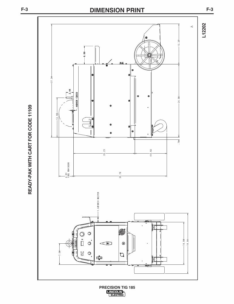
F-3DIMENSION PRINTF-3
PRECISION TIG 185
L122
02
READ
Y-PA
K W
ITH
CART
FO
R CO
DE 1
1109
A
19.81
14.00
24.00
1.66TORCH HOLSTER
6.00
6.00
2.44
2.44
7.00
30.78
.75
4.83
TOOL TRAY DOO
R
20.25
10.53
.46
.46DOO
R CL CLOSED
12.99
37.24
13.27

NOTES
PRECISION TIG 185

WARNING
AVISO DEPRECAUCION
ATTENTION
WARNUNG
ATENÇÃO
Spanish
French
German
Portuguese
Japanese
Chinese
Korean
Arabic
READ AND UNDERSTAND THE MANUFACTURER’S INSTRUCTION FOR THIS EQUIPMENT AND THE CONSUMABLES TO BEUSED AND FOLLOW YOUR EMPLOYER’S SAFETY PRACTICES.
SE RECOMIENDA LEER Y ENTENDER LAS INSTRUCCIONES DEL FABRICANTE PARA EL USO DE ESTE EQUIPO Y LOSCONSUMIBLES QUE VA A UTILIZAR, SIGA LAS MEDIDAS DE SEGURIDAD DE SU SUPERVISOR.
LISEZ ET COMPRENEZ LES INSTRUCTIONS DU FABRICANT EN CE QUI REGARDE CET EQUIPMENT ET LES PRODUITS AETRE EMPLOYES ET SUIVEZ LES PROCEDURES DE SECURITE DE VOTRE EMPLOYEUR.
LESEN SIE UND BEFOLGEN SIE DIE BETRIEBSANLEITUNG DER ANLAGE UND DEN ELEKTRODENEINSATZ DES HER-STELLERS. DIE UNFALLVERHÜTUNGSVORSCHRIFTEN DES ARBEITGEBERS SIND EBENFALLS ZU BEACHTEN.
● Do not touch electrically live parts orelectrode with skin or wet clothing.
● Insulate yourself from work andground.
● No toque las partes o los electrodosbajo carga con la piel o ropa moja-da.
● Aislese del trabajo y de la tierra.
● Ne laissez ni la peau ni des vête-ments mouillés entrer en contactavec des pièces sous tension.
● Isolez-vous du travail et de la terre.
● Berühren Sie keine stromführendenTeile oder Elektroden mit IhremKörper oder feuchter Kleidung!
● Isolieren Sie sich von denElektroden und dem Erdboden!
● Não toque partes elétricas e elec-trodos com a pele ou roupa molha-da.
● Isole-se da peça e terra.
● Keep flammable materials away.
● Mantenga el material combustiblefuera del área de trabajo.
● Gardez à l’écart de tout matérielinflammable.
● Entfernen Sie brennbarres Material!
● Mantenha inflamáveis bem guarda-dos.
● Wear eye, ear and body protection.
● Protéjase los ojos, los oídos y elcuerpo.
● Protégez vos yeux, vos oreilles etvotre corps.
● Tragen Sie Augen-, Ohren- und Kör-perschutz!
● Use proteção para a vista, ouvido ecorpo.

WARNING
AVISO DEPRECAUCION
ATTENTION
WARNUNG
ATENÇÃO
Spanish
French
German
Portuguese
Japanese
Chinese
Korean
Arabic
LEIA E COMPREENDA AS INSTRUÇÕES DO FABRICANTE PARA ESTE EQUIPAMENTO E AS PARTES DE USO, E SIGA ASPRÁTICAS DE SEGURANÇA DO EMPREGADOR.
● Keep your head out of fumes.● Use ventilation or exhaust to
remove fumes from breathing zone.
● Los humos fuera de la zona de res-piración.
● Mantenga la cabeza fuera de loshumos. Utilice ventilación oaspiración para gases.
● Gardez la tête à l’écart des fumées.● Utilisez un ventilateur ou un aspira-
teur pour ôter les fumées des zonesde travail.
● Vermeiden Sie das Einatmen vonSchweibrauch!
● Sorgen Sie für gute Be- undEntlüftung des Arbeitsplatzes!
● Mantenha seu rosto da fumaça.● Use ventilação e exhaustão para
remover fumo da zona respiratória.
● Turn power off before servicing.
● Desconectar el cable de ali-mentación de poder de la máquinaantes de iniciar cualquier servicio.
● Débranchez le courant avant l’entre-tien.
● Strom vor Wartungsarbeitenabschalten! (Netzstrom völlig öff-nen; Maschine anhalten!)
● Não opere com as tampas removidas.● Desligue a corrente antes de fazer
serviço.● Não toque as partes elétricas nuas.
● Do not operate with panel open orguards off.
● No operar con panel abierto oguardas quitadas.
● N’opérez pas avec les panneauxouverts ou avec les dispositifs deprotection enlevés.
● Anlage nie ohne Schutzgehäuseoder Innenschutzverkleidung inBetrieb setzen!
● Mantenha-se afastado das partesmoventes.
● Não opere com os paineis abertosou guardas removidas.

• Sales and Service through Subsidiaries and Distributors Worldwide •
Cleveland, Ohio 44117-1199 U.S.A. TEL: 216.481.8100 FAX: 216.486.1751 WEB SITE: www.lincolnelectric.com
• World's Leader in Welding and Cutting Products •