iLs SOME MATHEMATICAL MODELS AND …INFORMATION h,!•d W VAi SERVICE:;5. g Best Reproduced...
166
IAll SSY-TNIO-70 iLs SOME MATHEMATICAL MODELS "AND COMPUTER PROGRAMS FOR SMALL ARMS ANALYSES Approvwd Ir -:': , Edited by Distiibut'c-n U. . R.L. Simmons F.A. M alinoski r N.M. Hung _ DC Ad IEoc Small Arms Systems - .l Analysis Working Group -' FiAR Q1 1 I$J1 U I February 1971 L) . . SYSTEMS ANALYSIS DIRECTORATE U.S. ARMY WEAPONS COMMAND ROCK ISLAND, ILLINOIS N ATIO0NA.L T ECH NIC AL INFORMATION SERVICE W h,!•d VAi :;5 . g Reproduced From Best Available Copy
Transcript of iLs SOME MATHEMATICAL MODELS AND …INFORMATION h,!•d W VAi SERVICE:;5. g Best Reproduced...
IAll
SSY-TNIO-70
iLs SOME MATHEMATICAL MODELS
"AND COMPUTER PROGRAMS
FOR SMALL ARMS ANALYSES
Approvwd Ir -:': ,
Edited by Distiibut'c-n U. .
R.L. Simmons
F.A. M alinoski rN.M. Hung _ DC
Ad IEoc Small Arms Systems - .l
Analysis Working Group -' FiAR Q1 1 I$J1 U I
February 1971 L) . .
SYSTEMS ANALYSIS DIRECTORATE
U.S. ARMY WEAPONS COMMAND
ROCK ISLAND, ILLINOIS
N ATIO0NA.L T ECH NIC ALINFORMATION SERVICEW h,!•d VAi :;5
. g Reproduced FromBest Available Copy
SY-TNlO-?O
SOME MATHEMATICAL MODELS AND COMPUTER PROGRAMS
FOR SMALL ARMS ANALYSES
Edited by
R.L. SlinmonsF.A. Malinoski
H.M. HungAd Hoc Small Arms SystemsAnalysis Working Group
Systems Anlaysis DirectorateU. S. Army Weapons Command
Rock Island, Illinois
February 1973
ABSTRA\cr
A collection of some mathematic.A1 models and their computer programs
related to small arms are presentad. The modals encompass three areas:
interior ballistics, exterior ballistics and ta.'get effectiveness.
Ihe interior ballistic models includes five models for projectile
design, propellant charge, cartridge case, case design and cartridge design.
The exterior ballistics model provides two-dimensional trajectories. Eight
models are given for target effectiveness models: individual soldier, heavy
machine gun emplacement, bunker, hemisphere, squad, hidden point target in
area, helmet penetration and brush pcnetration. Some description of assump-
tions, formulas, input and output formats with numerical examples are given.
This work provides the basis for a parametric design analysis for :he light-
weight machine gun but has applications in other areas as well. The con-
tents are not intended to be exhaustive or conclusive, but to serve as a
point of departure to be added to or modified as opportunities permit.
i
ACKNOWLEDGEMENT
Many persons contributed to the development of the models and computer
programs compiled in this technical note. The individuals who arc the most
recent participants in preparation of the details of the work are specifically
recognized under the name of each model respectively. Without all these
contributors, no collection of this kind can be accomp.ished.
The working group thanks WECOM, in particular the project engineers
R. S. Thompson, J. Knoblach and K. L. Witwer, for providing an opportunity
for early application of the models to a parametric design analysis of the
lightweight machine gun. Thanks also are due to Cpt. R. H. Moushegian,
WECOM, for finalizing the conversion of all programs for WECOM usage and
preparing the note for publication.
Ad Hoc Srnall Arms SystemsAnalysis Working GroupR. L. Simmons, AMSAA, ChairmanF. A. Malinoski, Frankford ArsenalH. M. Hung, US Army Weapons CommandFebruary 1971
ii
TABLE OF CONTENTS
Abstract .. .
Acknowledgement ........................ ii
Table Of Contents ....................... iii
1. Introduction ....................... 1
-. Essential Input/Output Parameters ............ ............. 3
3. Interior Ballistics Models: ............... ................ 8
3.1 Projectile Design Model .............. ............... 8
C. 0. Bateman and R. J. Schlenner, FA
3.2 Propellant Charge Model ....... ................. 8
C. 0. Bateman, FA
3.3 Cartridge Case Model ................ ................. 9
4.. U. Bateman and R. J. Schlenner, fA
3.4 Case Design Model ................. .................. 10
C. 0. Bateman and R. J. Schlenner, FA
3.5 Cartride Design Model ...... ................ .11
C. 0. Bateman and R. J. Schlenner, FA
4. Exterior Ballistic Models ... ........... ............ 17
B. Wencour, C. 0. Batemai, and F. A. Malinoski, FA
5. Target Ettectiveness Models: ..... ............... .. 25
5.1 individual Soldier Model ...... ............... ... 25
H. K. Fallin, AMSAA
5.2 Squad Model ............. ..................... .. 41
M. J. Schmidt, H. K. Fallin and C. Gardner, AMSAA
liii
TABLE OF CONTENTS (Cont)
Page
5.3 Bunker Model ................. ..................... 76
M. J. Schmidt, H. K. Fallin and C. Cardner, AMSAA
5.4 Hemisphere Model ............... ................... 93
CPT R. H. Moushegian
5.5 Heavy Machine Gun Emplacement Model .. ......... .. 112
M. J. Schmidt, H. K. Fallin and C. Gardner, .MSAA
5.6 Hidden Point Target in Area Model .................. 135
H. K. Fallin, AMSAA
5.7 Helmet Penetration Model ...... ............... ... 149
R. J. Schlenner, FA
5.8 Brush Penetration Model ....... ............... .. 155
M. J. Schmidt, AMSA.A
6 . Kt ft e i . . . . . . . . . . . . . . . . . . . . . . . . 159
Distribution . . . . . . . . . . . . . . . . . . . . . . . . 160
iv
1. INTRODUCTION
This technical note is prepared by the Ad Hoc Small Arms Systems
Analysis Working Group in response to the request tor assistance by WECOM
(AMSWE-RES-C) for the project related to the parametric design analysis
(PDA) of lightweight machine guns.
The note is intended to provide some raticnal basis for olanning and
implementation of the incipient PDA of the proiect. It is neither intended
to be crnclusive nor exhaustive for obviously there are some missing areas
in regard to weapon dispersion and lethality models for examples.
Thus, the note should be viewed as a working paper reflecting the col-
lective effort of the working group for the subject at the time, and not
establishing a position.
Principally, the note encompasses three types of models: interior
ballistics, exterior ballistics, and effectiveness models. Descriptions of
assumptions, formulas, input and output formats with numerical examples as
well as computer programs are given. Although much more information is
needed to cover the subject more thoroughly, the level of sophistication of
the models Is consistent wi:h current practice.
The interior ballistics models can yield some initial design features.
The exterior ballistic model deals with plane motion. Some other models
for exterior ballistics can also be seen within the target effectiveness
models. The basic setting for the latter models is a stationary weapon
firing upon stationary, passive, point and area targets. No two-sided war

gaminý models are included, since the target effectiveness models presented
are considered to be more germane to an initial study of the project.
All the models have been operational and validated, except models 5.4
and 5.8, which are newly developed and should be employed strictly within
their own contexts as stated. All the computer programs have been converted
to 13M 360/65 and are current as of 1 February 1971. No particular attempt
was made to unify tie format or notations throughout the models and programs,
rather it was attempted to make each model as self-evident as possible. A
list of essential input/output parameters is also given. The references
cited include only directly relevant ones.
2
2. ESSENTIAL INFUr;OUrVPUT PAx,:ETFIRS
Nomenclature (Model Numbers) Units Notation
Aim point on hemisphere in x.,x and XIA,X2A,X3Ax, coordinates (5.4)
Air density (A, 5.4) :P
Averaga of the offsets (5.1) , ,
Ballistic limit velocity (5.7) ;ps VELE'BL
Barrel length (3.2) in BARLEN
Bore area (3.2) in BRAREA
Caliber (3.1, 3.2, 3.4) in CAL
Caliber of projectile (5.4) !: D
Cartridge volume (3.5) in CRTV6L
Cartridge weight (3.5) gr•ilns CARTWT
Case ]n.'rh-tn-diaamPtPr rartn (3.4) -(1.4)
Case -material (3.3) - •'?L
Case taper (3.4) mi in TPR
Case volume k3.3, 3.4) in CASVOL
Case weighr (3.3) grains CASWT
Center ci hemisphere in x,,x 2 ,x 3 t. A1,A2,A3
coordinaces (5.4)
Charge volume (3.2, 3.3) in CHGVDL
Coefficients of rounds's trajectory T(j),j-1,2, 5equations (5.2, 5.3, 5.5)
Component of standard deviation of range M PREestimation error (5.2, 5.3. 5.5)
Constant of proportionality (5.4) - B
Coordinates (5.4)
Coordinates of center base of bunker (5.3) m AT(fi,Gt(1)
3
Nomenctiture (Midel Numbers) Units Notation
Coordinates of tirst aimpoint (5.5, 5.3) m GAl
Coordinates of initial aimpoint (5.6) in XP,YQ
Coordinates of ranging-in point (5.2, m AZ,GA
5.3, 5.5)
Deflection in y (5.8) in Dy
Density of titi (5.8) m P
Depth of rectangular region (5.9, 5.3, 5.2) m D,RW
Depth ot titi (5.8) m D
Distance along the slope of front m DXedge of machine gun emplacement fromhorizontal plane (5.5)
Distance between aimpoints (5.3, 5.2) m DA
Expected fraction of the target F
incapacitated (5.2, 5.5)
Expected number of hits (5.1, 5.4) E(H)
Flechecte weight (3.1) grains FLWT
Gravitational constant (5.4) ft/sec2 G
Head diameter (3.5) in HDRAD*2
Height of bunker (5.3) m F-M
Height of individual man (5.2) m HM
Height of muzzle of gun above m YOground (5.2, 5.3, 5.5)
Height of target (5.8) in, m H
Helmet thickness (5.7) in HTHIK
Initial drag coefficient (4) CDI
Initial standard deviation of 1st round ft SXI10,SX210,SX310in xl,x 2 , and x3 coordination (5.4)
4
I
*
NcncnclltLre "!.2 d,!l Nuxnbcs) r'rit Notation
Initial standard deviation .)f 1st ound ft/sek SVIl0,SV210,SV3]O
veiocity in x,,,and x coordinates (5.4)
Initial standard d,:viaU.eno of offset in tt SX130,SX230,SX330
x,,x,, and x, coordinates (5.4)
Initial standard deviation of offset in ft!sec 1:X130,UX230,LX33Q
velocity in x,x 2,* and x coordinates (5.4)
Initial standard deviation of subsequent ft SX120,SX220,SX3JZ
rounds in xlx 2 , and x coordinates (5.4)
Initia] standard deviation of subsequent ft,/sec SVI20,SV220,SV320
rounds velocity in x 1 ,,x, and x
coordinates (5.4)
Initial velocity (4) T/,see C'0O
Length of rectangular region (5.6, 5.8) m RL
Miaximum number of bursts all-wed to achieve - IS
desired level of effectiveness (5.2)
Maximum number of rounds allowed to - Mzrange-in (5.2, 5.3)
Heen ot all tirst projectiles in the I x ,
bursts (5.1) Y
Mean of all subsequent projectiles in x 21Ua burst (5.10 Y2
Minimum r)ight time (5.4) sec TI'MIN
Muzzle velo.tity (3.2, 3.5, 4) m/sec VELM,VD
Number of almpoints (5.3, 5.2) - NA
Number of men in the squad (5.2) -N
Number of proiectiles/round (5.2, 5.3. 5.5) - ANP
Number of replications (5.6) - NR
5
0 0 0 0N 101 *t 6.W1

N,-u.r•nct,•t oll ubr) Units Notation •
Numnber of relctn/agtengage-1en-t NREP
(5.2, 5.3, 5.5)
Number (if rounds/.Aimpoint (5.3, 5.2) N RA
Number ot r-o,inal/bursL (5.1, 5.5, 5.4) NNRA
Number of ro~ndL,5';eep (5.6) - N
Number ot sweeps (5.3, 5.2) .NS
Peak pressure (3.2) Kpsi pPRESS
Penetra•.or dia~met~r (5.8) in PNDIAM
Penatr&Lor Mass (5.7) grainý pNMASS
Probability of tilt with at least one P(l÷)
rd/buxSL (5.1)
Probability )f incapacitation (5.1) P[
Probability of inc~apacitation given P(1/H)
a tilt (5. 1)Projectile cross--ser.ion area (4) in2 A
probectile diameter (5.7. 5.8) irm,in PRDIA.1-1, PD
Projectile length 03.1) in BUILEN
Proiectlle mass (5.4, 5.7) slug, grain •xm, PPEVASS
-'p
Projectile vilumt (3.1) in sUT atiL
Projectile weight (3.i), 3o2, 4) nrtins PWT,XM,PW
Propellant w5igh5 (3.2, 3.3) grains FRONT
Quadrant elevacion angle (4) radians ANG0
Radius of hnmusphea'e (5.,) ft Nl
Range (5.1, 5.r , 5 .6) M5.t R.XR
Rnuemb w ep~. Gcner of rectangularp (M6 -N
region (5.3. 5.2)Rangf to nearest portion of target (5.() it RMIN
Round identification (taio 5.6) - (proabiit oficpctto givn • ( / H)
Nomenclature (Mode. Numbers) Units Nctation S
Sabot mass (5.7) graini SAMAS
Shoulder angle (3.4) degrees ANGLE
Shoulder diameter (3.5) SHRAD*2
Standard deviation of (x 3 y 3) (5.1) J x 3 'x 3
Striking energy at the target (5.8) Jules ES
Striking velocity (5.8) mr/sec VS
Subsequent rrojeutile dispersion (5.1) a x2,x 0
System momentum (3.5) slug ft/sec SYSMOM
Time increment (5.4) sec DI
Total delivery error a a
Type (3.1)
Velocity of sound (5.4) ft/sec AO
Velocity retardation (5.8) ft/sec VR
Width of bunker (5.3, 5.2) m WM
Width of target (5.1, 5.6) in W
Width of target area (5.6) m WR
7
S
S
3. INTERIOR BALLISTICS hODELS
3.1 Projectile Design Model
a. Steel core bullet is -caled from 150 grain 7.62rmm bullet.
b, Lead core bullet is scaled from 68 grain 5.56mm bullet.
c. Flechette is scaled from 25 grain 7.62mm flechette.
d. Addition3l design infornation is contained in lIalmet P'enetration
Model.
Item Des_ ar Units Remarks
Inputs:
Caliber CAL inches
Type TYPE name
Outputs:
Projectile weight PWT grains
Projectile volume BUTVOL cubic inches
Projectile lengch Bu'LkS iInches developed Only
Flechette weight FLWT grains for flechett.s
3.2 Popellant Chare Moal
a. Loading density is fixed at 235 grains/cubic inch.
b. Manning Interior Ballistic Curves as fit by Mr. Whyte of General
Electric Corporation are used. The reference is Engineering Design Handbook
AMCP 706-150, pp 2-42 to 2-45 [1] .
c. An iteration method is used. Although failura to converge has not
been experienced, convergence is not unconditional, and error recovery pro-
cedures should be added by the user.
See Reference
8

d. Al.though convergence is carried to 0.1%. actual accutacy is about
2%.
e. If no entry (or zero) is made for bore a-ea, the aren is calculated
from the caliber. S
f. Barrel length as used in this routine actually refers to the dis-
tance the bullet travels in the barrel. The actual barrel will be somewhat
longer.
Item ator Unis Remarks
InputS:
Projectile weight PqT g-ains from above
Caliber CAL inches I
Barrel length BARL." inches see note
Muzzle vl.ocity VELM fe'%tJseC
Bore area BRAREA square inches will be developedfrom c3liber if 0
Peak pressure FR£$S Kpi * *
Cutpu.:s:
Propellant weight PRPPWT grains
Charge volume CHGVOL cubic inches
3.3 Cartr dge Cage Model
a. Case weight is calculated from a formula devised from existing
case data.
b. Correction is made for case material.
c. An error nassage is produced if the pressure is more than 40K psi
in an aluminum case.
4. The case volume is calculated as the sum of the metal volume and
the propelLant volume.
9
b ttt"
I
I
Item Designator Units Remarks
inputs:
propellant weight PROPW4T grains from abo'a
Charge volume CHGV0L cubic inches "
Case material MATL nJle
Outputs:
4 Case weight CASWT grains
Case volume CASVqL cubic inches
3.4 Case Design Model
a. Preliminary head radius is calculated assuming a cylindrical case.
Shoulder coordinates are calculated by point-slope formulas. Total volume
for the assumed dimensions is calculated and compared to actual. A new
head radius is calculated and the procedure repeated until the calculated
4 volume is within 0.01. of the actual value. B
b. No entry (or zero) for shoulder angle will result in 40 degrees
being used.
c. Future revisions of this model will contain default values for
length-to--diameter ratio and case taper.
d. So far as is known, convergence of the iteration routine is un-
ccnuitional.
e. This model does not assure that a flechette is fully contained in
the cartridge case, as is the current practice. Flechette cartridges cal-
culated by the program will be longer and thinner then standard cartridges.
10
0, • 0 S 0 S 0 0 0 *
Item Designator Units Remarks C
Inputs:
Case volume CASV0L cubic inches from above
Shoulder angle ANGLE degrees value of 40'assumed if 0
Case taper TPR inches/inch if zero entereduses .01746
Case length-to- RATIý dimensionlezs to be optimized
diameter ratio default value - 4
Caliber CAL inches from above
Outputs:
Head diameter HDRAD*2 inches
Length from head CASLEN inchesto shoulder
Shoulder diameter SHRAD*2 inches 3
3.5 Cartridge Design Model
a. Cartridge weight - sum of component weights
b. Cartridge volume a sum of component volumes * ec. Muzzle energy - 112 MV.
d. System momentum - tormula from [ 9]
* ii
* S
* S
t • •9 • • • •11

$JOB 'LMG MQDELS'jKPx29tTlP0E23O0CC SY-TNIO-70 3 INTERIOR BALLISTICS P1,DELS OCT.-70
L SY-TNIO-70 3.1 PROJECTILE DESIGN PODEL OCr.-70C 20 ASCII TYPEMATL
25 FCR4MAT(lH1)30 FORMATi *OCALIBER -IEL5.61 IN4/)40 FORMAT ISFl0.0)
wR I U(6925)REAOI5,401 CALWRITIA6130) CAL
2COO FORMA7l11O)REAOE5,2000) NiYPE
5 0 FORMAT ( IX t IYP E ( I- ST EEL 2-L EAD q3-FL ECHE TTE) 15WRITE~b,50) NTYPE
C 80 *STEEL CORE BULLET SCALED FROM 150 GRAIN 7.62 HM BULLET90 II-(NTYPE. NE. 11 GO TO 150100 PWT-I50.*(CAL/ .3085)#"3LIU 5UTV0Lz .0701*1 CAL/.3085'It*3120 BUTLEN-L.259*CAL/.3085
FLwT=0.O130 GO TO 300
C 140 *LEAD CURE BULLET SCALED FROM 68 GRAIN 5.56 MM BULLET150 IF(NTYPE. NE. 21 GO TO 210160 PWT=6R.*I CAL/ .2245)**3170 8UTVOL=.0273'I CAL/.224S1**31.80 bUTLEN'-.9406'CAL/.2245
FLWT=0.0t90 GO TO 300
C 200 tFLECHETTE SCALED FROM 25 GRAIN 7.62 MM FLECHETTL210 IFINTYPt. NE. 3) GO T0 270220 PWr-cAL**3*(991.97+2307.5*CAL I230 BUTVOLz .0679*(CAL/. 3085 )**3240 BUTLEN=1.259*CAL/.3O85250 FLWT-851.48*CAL*$3260 GO TO 300270 CONTINUE280 PORMAT(lXtOUNDEFINED BULLET TYPE')
WRITE(692801GO Tfl 1310
300 CONTINUE310 FORMAT(IX,'PROJECT[LE WE;GHT z'2X,EI5.89 GRAINS')
320 FORMATilXt'BULLEr VOLUME *16X*EIS.8' CU IN,)WRITEI693Z0) BUTVOL
321 FORMA1E1X,IBULLET LENGTH ='bXEI5.8' IN')WRITE(6#321) OUTLEN
330 FORMATIIX,'FLECHETTE WEIGHT s'3,EI.5,81 GRAINS')WRITE(6p330) FLwT
12
.3)0 *0 00 40 *

C
380 F0HMAT18FIO.0)REAO(S,38U3 BARLEN, VELM~bRAREA, PPRESS 4
370 FORMATULXt'BARREL LENGTH '16XICE15.B' iNl)WHITE(6,3701 BARLEN
390 FORMAT(IX,'P4UZZLE VELOCITY z'4X,Ll5.8' FT/SECO!WITL(6,M~) VELMIF( BkA~lEA.I:Q.O.O)8RAREAý3. 1415914.O*CAL**2
410 FORMAT(LX,IBORE AREA all0XsF15.81 SQ IN')WRITC(6,-.lO) FRAREA*
430 FORMAT41X,EPE~AK PRESSURE =16XsE15.8' KPS111WHITE16,430) PPRESS
460O PROPWT=PWT/5.470 C14GVOL-PROPWT/235.480 CMR=PROPWT/PWT490 XPR-( (6RAREA*DARLEN)4tHGVOL)/C,iGVOL500 IF(XPR.LT.1O.1 GO TO 530 4510 VX21.183.IXPR-LO.)*I .0292)-.C00833*(XPR-LO.d**2520 GO TO 540530 VX=1.183+IXPR-10. )*.0275..CO0381*(XPR-10.)*t3S40 IF(CMR.Lr..8)G0 TO 570550 VC=3820.+(CMR-.8)* 1516.7-166.7*(CMR-.8I*b2560 GO TO 610570 IF(CMR.LT..5)GQ O 70 C0580 VC=3140.s 1CMR-.5)*29t6.6-2166.*(CMR-.5)**2
600 VC=3140.4+(CMR-.5$2150).-35004(CMR-.51*02610 IF(PPRES;.LI.55.)GO TO 640ebI0 VP=.99.(PPRESS-55.)I.O021b30 GO TO 650640 VP=.99(PPRESS-55.)*.0015-.CC019*(PPkESS-55.)**2650 VLETY=VX*VC*VP660 PROPWT=PROPWTS41.+(VELM-VLCTY)/'VELMI670 IFIARS(VLCTY-VELM).GT.VELM*.001)GO TO 470b80 FORMATIIIX,'PROPELLANT CHARGE ='2X,E15.81 GRAINS')
wKITE(b,680) PROPWT690 CHGVflLaPR0PWT/235.700 FORMAT(I.XvICIARGE VOLUMEF =16X,,E15.8' CU JNf) 4
W9-I*L-'.-7Q0% CHCGVOL
13
C 720 3.3 CARTRIDGE CASE MODEL(
RLAO(5, 721 )MATL721 F-URMAf(I110)730 F0RMArI/I CARTRI*)GL CASE MATERIAL il-STEtL,92-ALUNINIUM) -01I5)
%RITE(6,730) MATIC 750 *DEFAULT VALUE ASSUMES t8RASS
760 CASWT=lPROPWT .2.5I8)/.2084770 CASVCL=CFIGVOL .LASWF/2 156.
C f80 *STEýL CASE z9O OF- BRAS CASE WT., DENSITY -1960 GRAINS/CU.IN.IvO IF(MATL.NE.1) GO TO 840buo AWWT=CASwt*.9R1O CASVOL'C"'.GV0L tCASWT/ 1960.820 GO TO 915
C 830 $ALUM. CASE -37.6 OF BRASS CASE, DENSITY a 7U7 GRAINSiCU.IN.8~4O IFINATL. NE. 2) GO TO 915
C 850 *PEAK. PRESSURE f-OR ALUMINUM MUST NOT EXCLED 40 KPSI880 IF(PPRESS .L[. '40.)GO TO 89087U FURMAT11X,'PEAK PRESSURE TOO HIGH FOR ALUVINUM')
WRITE46,870 )880 GO TO 1310890 CASWT=CASWT*.316900 CASVOL=CHGVUL.CASWT/701.ý10 FOIkMAT(1X,'CASE 1VEIGHT '114X,F15.5o' GRAINS')915 WKITE1b,')l0) CASWY420 FORMAT(X11O'UTS1IDE CASE COLUMN vl6x,El5.8,' CU WN)
WRITE(6*920) CASVOL
CC 940 3.4 CASE DESIGN MODEL
960 FORMAT(8fflOýOlREMDIS,9 96 ANGLE; TPR 1 KATIO
11-(ANGLý-.EQ.0.)ANGLE=40.90s FORMATIIX,' INCLUDED SHiOULDER ANGLE ='2X,EI5.81 DEGREES')
WNIIE(6,950) ANGLEIF(TPR.E.J.O.)TPR=.017 456
980 1-ORMATIIX,' INCLUDED TAPER OF CASE -'3XsE15.8' DEGREES')WRITE(6,9B0) TPRIF (RAT 0. EQ .3.0 )RAT IOm4.0
1010 FORMAUfIX,'L/D RATIO OF- CASE~ ='8X,E15.81WRIMF6910OLO) kATIO
1030 HORAOC (CASVOL/b.2F33/RAT (0)**. 3333331040 SLOPE=-TAN(ANGLE/2.)1050 C4SLEN=H0RAO*RATIO*2.1060 1MPiCAL/2'.-SLQPE0CASLEN1070 CYLEN=IHORAD)-TMPF/ISLOPE+TPR/2.)1080 SHiNAS-rTPR/2.*CYLEN+H-DRAO1090 TVOLx3.14159/ 3.*)HDRAO**24'HDRAD*SHRAOSHRAD**2)*CYLEN1100 SVOLý3.14159/3.*(SHRAD**2+SHRAD*CAL/2.4(CAL/2. )**2I*IC.ASLEN-CYLEN)1110 F'VUL-TVOL+SVOL
14

1120 HKADVHkAP*)it ;IAf*ICASVOL-FVOL)/13.*CASVOL)1130 19( %BS(CASVOL-FVflL).GT.CASVOL*.C0Cfl)G0 TO 1050114,0 FOkMATllX,'HE4D DIAMETEP ml12X,E1S.8' IW)
HIJRAS2=HDRAO*2.0
1150 fOkMAT(1X90HLAD TO SHOULDER LENGTH =l2X,E15.8' IN*)WRITE(6*11501 CYLEN
1160 FOkMAr(1X,'SH0ULOER DIAMETER -'OXEI5.8' IN*)SHNIMA &2 = SHR A#2.*0biRIIUo, 1160) SHRA02
IL70 FOKMATHtX91CASE L~ENGTH =114X,E15.83' IN')WRI~TE(6,11170) CASLLN
C1180 3.5 CARTRIflGE OESIG4 MODELcC1190 *CARTRIPGE WEIGNT1200 CAkTWT=PWT +iR0PWT*CASWT1210 fýOHRATI1X,'CARIRIDGE WEIGHT ='9X,E15.81 GRAINS')
vqR1TE(6. 1210) CARTWT(1220 *CARTRIDGE VOLUME12370 CdVOL=CASVOL+BurVuL1240 IORMAM~X,SCARTRIOGE VOLUME =19X,EI5.8$ CU 1N¼I
WkR'.E(6, 1240) CRTVOLC1250 *MUZZLE ENEAGY 4
t260 ENRGY=PWT*VELM**2/45Q383O.1210 FORMAT(UA,'MUZZLE ENERG.Y w'12XvEl5.8l FT-LBSI)
WRIrE16,1270) ENKGYC.12B0 *SYSTEM MOMENTUM1290 SYSMOM=.444E-5*PWr*VELM*( 1*-5.03E-5*VELM) ,.023*PKOPhT1300 FORMAT(IXSYS(EM MOMENTUM z'IOX,C115.80 Ft-LB1S')
WRIFE(6,13001 SYSMOM *1310 CONT INUE
15
LID
II
00-0
* 4
Nunerical Exalrple:
CALIBER = 0.30000000t 00 IN
TYPE (I-STEeL,2-LEAD,3-FLECHETTE = I
PRCJECTILL WEIGHT = o.137939TOE 03 GRAINS
PULLET VOLUME z O.b446385OE-01 CU IN
PUtLLET LLNGTH = 0.12243100E 01 IN
FLI-CH4TTIE WLIGHT o.0000OU00E 00 GRAINS
hARRLL LENGTH = O.20000000E 02 IN
MUZZLF VELOCITY 0 .30000000E 04 FT/SEC
fl(A[ AREA - 0.70685740E-01 SQ IN
PEAK PRESSURL = U.55000000E 02 KPST
PKCPELLANI CHARGE = O.51575940E 02 GRAINS
CHARGE VOLUME a o.21947200E 00 CU IN
CARTRIDGE CASE MATERIAL (I-STEELZ-ALUMINIUM) I
CASE WEIGHT = 0,2336t080E 03 GRAINS
GUISIOE CASE C0LkJMN 0 0.33866120E 00 CU IN
INCLUDED SHOULCER ANGLE 0,40000000E 02 DEGREES * q
INCLUDED TAPER OF CASE $ O.1745999CE-01 DEGREES
Li/O RATIO OF CASE 0.40000000E 01
.... DIAMETER : .B607270E CO IN
utiAU TC SHOULCER LENGTH n 0.19177170E 01 IN
SH(JULI)EK DIAMETER = 0.4545835CE 00 IN
CASE LENGTH 9 0.19522670E 01 IN
CARTKIDGE WEIGHT x 0.4231264CE 03 GRAINS
CARTRIDGE VOLUPL - 0.40312510E 00 CU IN
MUULE ENERGY = 0.27564670E 04 FT-LBS
SYSTUP MOMENTUM 0.27463450E 01 FT-LBS
* 6
* 0
16
* 6
4
o• o
m m

*i
Cog)
*
.. EXITERtOR ALLISTIC5 MODEl.
This pc"ý;ram reads in values of the diag OLul ticiunt, C D2. as a function
ot velocity, V , (or calls on a function to supply CD2) then proceeds to
into;grarc by contraction iteration to yield thv height y, range x, the rime
of flight. t. and the instantaneous dfngle ,t the trajectory wiLh respect to
the horizontal, AINC. Parameters which must be supplied Are as follows:
* 0
Parameter l'roiram Symbol Units
Projectile weight XN grains
Quadrant elevation angle A.'L)o radians
Proj C.S. area A in •
Muzzle or initial velocity VO meters/sec
Initial drag coef (C;D1) CDI ---
Air density lbs/ft
Basic Relations: * * *
- _pAvIv; CD(V)_
dtD
d%- -PAv-V C D(v)x -2SxD m
dt m
Let c- "A * ,r v cos-
Then, dvx dt dvd--"-' (v cos•) - cos• 7 - v sin, 'A ' *
-_L '..V ....
D
dt 1 v tana d- )•ccd D(V)v (
17
t
S
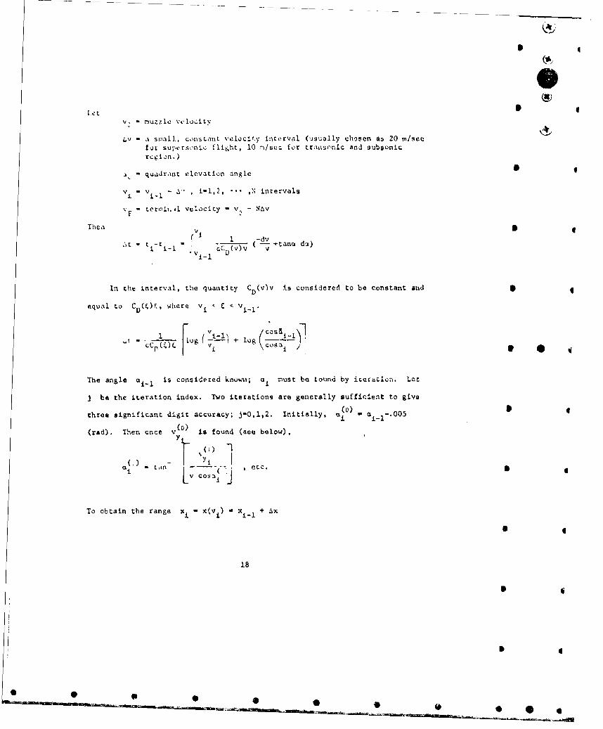
let IV. - nuzzle velocity
LV - a small, consLant volaclt.y interval (usually chosen as 20 m/secfor superso•nc flight, 10 ri/ser for traesonic and subsonicregion. )
- quadrant elevation angle S
V1 - v L- - A% , i-l,2, ,N intervals
V- termliail velocity - v, - NAy
Thea vi
r 1 -dvt- t- j - cC (v)v - +tana do)
In the interval, the quantity CD(v)v is considered to be constant and •
equal to CD (0s, where v C < v .
r on (.-___) o log K5--
The angle a el is considered knowni; ai must be tound by iteiaLion. Let
j be the iteration index. Two iterations are generally sufficient to give
three significant digit accuracy; 5-0,1,2. Initially, -i a 005
(ad). The once v (0) is found (see below),) - 7 t I
oc - tan Yetc.Lv Cosa•
To obtain the range x. -x(vi - xiI + ax
18
*
*
0 _ _ _-

dv dv
dt x jx X c (vxv
dx 1 (cTv a dv - v sinri d'-j *
cLCD (v) v
A os 2(X I 4.-I i-i whr ,ItX - C(wi v COSO1. L hr i
In practice, (CD*v)a the average valu~e over the ith interval, I's
used for 1L.. , and Coais used for che quantity co-a-w)C OcC (v) av UW
D ( D' ai C (w)
To obtain the height yi Y (vi) . -1 + L
tY-c -C D (V)V-V - 9
- IC~VJD k *ifmin - K
v -Vt - - f: CD(v)v 2 sina dt
VYi a V Y- - &t- CC D(U)U sinu(u)ýýt *where v, < u < v~ 1
Initially, v>, . v 0 fin 00
In practice, (C D mv'sinok) avi i used fur C D (u)u2 a ina(u) . Then
finally, y1 +j V dt. 4
:L yi-1Yi
19

I
NunerLcal Lxarple:
Input:
vi VT VINT
1000, 10. 10.
* 4
Output:
V2 X ANG
0.99000000C 03 0.264520810 02 C.?65863510-01 -o.263178020-03(.98O0UOOOE 03 0.528944300 02 C.53431313D-01 -0.531627640-030.97000000C 03 0.793237970 C? 0.805393360-01 -0.305502490-030.96000000C 03 0.105740360 C3 C.107915240 00 -0. 08496480-020.95000000C 03 0.13214375n 03 0.13556427D 00 -0.13701862D-02O.94000000C 03 0.l58533h20 03 0.163492050 00 -0.166114800-020.-3000000C U3 O018,go10690 C3 0.1917C4720 00 -0.195864230-020.92000000C U3 0.211274740 03 0.22C208840 00 -0-22622726D-020.91000000C 03 U.237626620 C3 0.249Il520 00 -0.257245450-020.90000000C 03 0.263967250 03 0.278120400 00 -0.288941670-020.890000000 03 0.290Z978f1' 01 C.1U0'54b6L) 00 -0. 321 3460-0Z0.68000000C 03 0.316619780 03 0.337290110 00 -0.35446669D-320.87000000C 03 0.342914920 C3 C.36736917D 00 -0.388348600-020.86000000C 03 0.369245290 03 C.397790940 00 -0.42301495D-020.85000000C 03 0.39555323D 03 C.42856621D 00 -0.45849663D-020.840000000 03 0.4218b1400 03 0.459706510 00 -0.4948265OD-020.83000000C 03 0.448172730 03 0.491224150 00 -0.53203951D-020.8200U000C 03 0.474490490 04 0.523132280 00 -o.570172900-020.d1000000C 03 0.50818250 C3 0.555444890 00 -0.609266310-020.800000000 03 0.5271ý,9900 03 C.588176920 00 -0.61936202D-02 440.790000000 03 0.55351964D C 3 C.621344270 00 -0.690505090-020.780000000 03 0.579902010 03 C.654963840 00 -0.732743630-020.77000000C 03 0.60h311880 03 0.689C53670 00 -0.77612898D-02
Note:
The user must nrovide terminatic'i criteria for execution.
20
ID
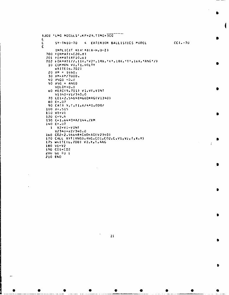
$JOB 'LOG MOCLLS.,KP=29,TIME.3ýCC-cc SY-TNIO-70 4 EXTERIOR BALLISTICS MODEL CC.i.-70
IMPLICIT REA**8(A-H,U-Z)700 FORN'ArI4E2O.8)701 ý-OiMAT48F10.u)702 I-OF'WAT(//,II1A,'V2#, 13x,'X',16xq,T',1tXpANG'/I10 CU?'MON v09T1.VFLfly
WRITE I 6,702)20 XM =16630.30 XMzXM/17000.40 ANGO =0.050 ANG =ANGO
VELOYO0.080 REACI5*7011 vl.VrVINT
VI 340=V1/340.O70 CC1z2.54b48*G6CRAG(Vl3340)80 C-.0790 CATA YrT,TI,Xi4*0.000/
100 Ax.515110 VO=VI120 G=9.8~130 C- 1.b4*rO*A/ t44./XM140 Cm.07
I V2zVl-VINTV234U-V2/34O.0
160 CDZ=2.54648*C6DKAGIV?340)170 CALL XYT IANGO,ANG.CD1,oC02,CVlV~ T9X,Y)175 WRITE(8, 100) V2vXtT,ANG180 V1-V2190 C01-C02ouU (ui 1 u 1
210 END
21
0S

43c TWAJI-CTORY
Z iU SUEn0JT INF XYTI ANG0,ANG,CnI,C02,CVl.V2,T,XYIIMPLICIT tRfAL*08CA-H,O-1)
240 COP'MON VO , Tl, VELLY250 VI5AN~ .%S V2+'ýil26~0 CATA G9O02~70 ANGI=ANG280 AV=.L~*IC02*V?*V2+C,0I*VI*Vl i*DSINIA(NGI290 AN(IANG-.0005300 CO 310 K=1I,2310 Cf=2*( l/V2-1/V1 )/C/ICC2#COI I320 CT=CT.2/C/(Cfl?, 1I)*DLOG(DCOS(ANGI)/OCOS(ANGI 2/VBAR330 T=1+[CT340 IF (K.EO.2) VELOY-VtlLDY+C*AV*UT350 Y(3tll-VELL)Y-G*T+V0*0SINqANG0'I3tbO ANGxDATANtYO0T/V2/OCDS(ANGl)370 CONTINUL380 CX=2~001.G(V1-/V2 I/C/(CC2+COII*0CCS(AN(.'.390 X= Xi+0X400 Y-Y-.5*IC,*(T*Tl) +C*AV9DTI*DT-VELDY*DT4.DI*V0*DS1N(ANGO)410 TlIf450 RETURN
4440 ENC
4
22
If

FUNCTION G6E2IAG(A3IM4PLICIT ,iEAL*t3IA-HtO--L)
11 FOR?'aT (27H EkROR M IS LESS THAN ZERO. IFNfF.~Cu,uEqF) = OA*[C+A*CU)+A*(E4A*F))IFIA.LT.O.) GO TO II F (AAL. .053 1 GO TO 2IF(A.L.E. .233 ) GO TO 3IF(A.LtE. .863 ) GO TOj 41 F IA.I.EO. 1.033 1 GO TO 5IF-(A.LE. 1.24 ) GO TO 61 F( A .L E. 4.06 )GO TO 7IFIA.11. 4.45 ) 6O To 8G6= (C.V)O I9997O0 *12062316*A 2**2- I.. /A/A6O 0 TO0t
C6=0.0GO TO 10
2 G6=.100302406O TO 10
3 Gb=FN(.094823643, .21t293130,-3.383?CCO*15.5394379-24.126021)GO TO 10
4 C6=VN(IjI.0b027#-.13469650, .33t:35169p-.45T399039 .24588434160 TO 10
5 (26-FNI-118.325929 '5I5.9336S,-84C. 14262, 005.640569-t62.96801)GO 10 toJ
6 G6=FN( -68.123779, 23O).6979go-292.13472, 164.38222o-34.682020)GO TO 10 *
1 Gb=FN(.14540526, .11561148.-.10352627p .C26467183v-.00223468398)Gc 70 10
8 G6=FN( -.489761209 .625C2782,-.24248594,.040170705,--.0024540220I10 G6CRACj -G6
IkETURN&J4C
23
IMPLIC IT REAL*d(A-H,GOZ)
Kr (a *k C .,0 ( #V [ *(-+I
Hi-. TURN
t4ETUHN
30 I~ -. 3 .54
RE~TURN
40 IF-CV-1.114s45,5O4', 1-)AIýK((.32111lol6~l,AIC108637E
2 v-.~t48E,3989I
RE-TURN1)'0 IFIV-1.1815
5 e5 5 06 0
55 UAC.ý0I .422405h8LZ,-.1138,04bE3, . l254'51F 3,-. 30651663E2)
80 1 E,( V 1 6b5 1b, 1>0
t4E TURN70 IF (V-I .45)75t?!tA
4 ~FORAC--K(.1163914t~?,.23262008Et~l'3i~AS,-36084IALTURNN
80 Ii (v-I .tu85,8 s,9 O
8S f~iiACzK0(-'10f59 ;' 6 2s *1C34383El,-.81949621v.1
8 8 3 l 93 )
K&ETUkN
100 1 F (V - 2 . 4 105,105, 110105P FGAC=KD(.6177b329,-.39160117,.1L002705Ill1
3 3 3 64E1
RETURN
110 MFV-3.2)1lS. 115,l2(O
a 12U I F (V- 4 . 2)12 5t125 9 1 3 0
121) FCkA~uKU( . 625h304E-1 12 5C397 3 #.55164 L 8BK-16954E-
Rt: t U4 N130 FC4AC~zKDI.IU~0-p().sO)
411 URNtN L
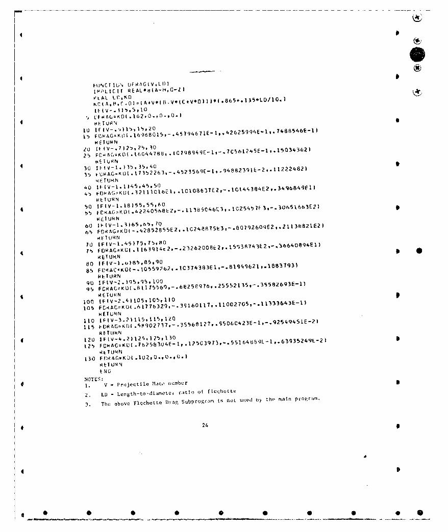
4 ~NOTES :I1. V -Projectile .1Iact, number
2. LD - Length-to-diaMC*e raitio of flehette~
3. The above Flechette Drap, Subprogram~ is not UsedI tb the mai~n ptogram.
e 24
0
* S
Ice)
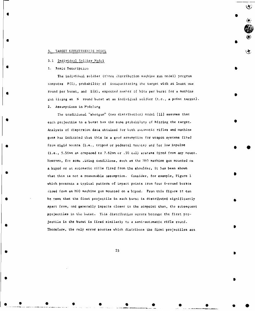
5. TARGET EFFECTIVENESS MODEL
5.1 Individual Soldier Model
I. Basic Description
The individual soldier (three distribution maQhine gun model) program
computes P(I), probability of incapacitating the target with at leest one
round per burst, and E(H), expected number of hits per burst for a machine
gun fiLing an N round burst at an individual soldier (i.e., a point target).
2. Assumptions in Vodeling
The traditional "shotgun" (two distribution) model 11] assumes that
each projectile in a burst has the same probability of hitting the target. •
Analysis of dispersion data obtained for both automatic rifles and machine
guns has indicated that this is a good assumption for weapon systems fired
• from rigid mounts (i.e., tripod or pedestal mounts) and for low impulse •
(i.e., 5.56mm as ccmpared to 7.62mm or .50 cal) systems fired from any mount.
However, for some 1.ring conditions, such as the M60 machine gun mounted on
a bipod or an automatic rifle fired from the shoulder, it has been shown
that this is not a reasonable assumption. Consider, for example, Figure 1
which presents a typical pattern of impact points irom four 6-round bursts
iired from an MO0 machine gun mounted on a bipod. From this figure it can
• be :een that the first projectile in each bursý is distributed significantly
apart from, and generally impacts closer to the aimpoint than, the subsequent
projectiles in Lhe buiit. This d•-tr '-uto occurs because the first prc-
Jectile in the burst is fired similarly to a semi-automatl.c rifle round.
Therefore, the only error sources which distribute the first projectiles are
* 25
* S4* *0 0 •
0 p
SUBSEQUENTROUNDS . c•
ACTUAL AIM POINT +FIRST ROUNDS
THEORETICAL
AIM POINT *
FIGURE I Typical Burst Pattern of an M60 Machine Gun Mounted on a Bipod
26
I
e • •• • o •• •D
*
round to-round dispersion and aiming error (delivery error); whereas, the
subsequent projectiles hove an additional error source due to weapon move-
mont which tnduces a separation of thr first and subsequent projectiles (the
magnitude of which apparently depends un both the rigidity of the mount and
the impulse of the machine gun). Consequently, for weapon systems fired
from non-rigid mounts the first projectile of any burst will generally have
a higher probability of hitting the target than the subsequint projecýtiles.
Another assumption in this model is that each pcojpctila in a 0urst is
distributed as a bivariate normal with tha horizontal (x) coordinate of each
projectile distributed independently from the vertiual (y) coordinate.
These two assumptions are incorporated together to form the folloving three
bivariate normal distributions which form the basis of the individual soldier
(three distribution machine gun) model:
a. Distribution of the first projectiles in buists about the actual • * 4
aim point.
b. Distribution sf the subsequent projectiles about their centers
of impact. *
r. Distribution of the offsets of the subsequent projectile centers
of impact from the corresponding first projectile.
The assumption of a normal distribution restricts the use of this model*
to short bursts.
SeveraŽ. other assumptions made in this model are as follows:
a. The individual soldier is represented by a vertical rectangle of
height 1i an1 width W, whose base is located on a horizontal ground plane. * 4
27
* 4
0 0 0 0 S *
"pi.nt it wI•,..:, thi ml hine gunner aims his weapon (the theoretical
ad::pJift) as 1�,teJ at the center base of the rectangle. However, no
praviston is madle in tEie modaI to determine effectiveness due to projectiles
t-h.'L • t • Lh
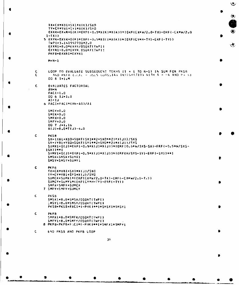
b. A Gaussian (16 point) integration formula has been used to evaluate
the Intoirals Ln Ehe basic formulas foz P(I) and E(H). This formula is
-elined as Lollows:
.b 16t •(x)dx - (-a) i Gl f(xi)
where.x- (h-a) T *- a
and G T known constants (weights).
3. Basic Formulas p
ANISSA TM-33 (5] presents the derivations of the formulas for ?(I), the
probability ot iucapacitating the target with at least one round per burst
and E(II), the expected number of hits per burst, for a machine gun firing
an N round burst at the center base of a single rectangular point target.
Trre following no.acion was used in the report:
P(T) - probability that no projectile in an N round burst
incapacitates the target
PG - probability that no subsequent projectile incapacitates
the target
'If.I - probability that the first projectile incapacitates the
target and no subsequent projectile incapacitates the
target
P(S) - probability that the subsequent projectile hits the target
P(T') - probability that the first projectile hits the target
The final effectivenese formulas derived in the report are:
P(I) I 1 - P(f)
where _P(f) - I(T.) - P u, TS)
andE(H)- P(F) + (N-1) • P(S).
Since, by definitionI
P(Q) - P(I/H) - P(H)
whereP(I/H) - probability of incapacitating the target given a random hit
P(H) - probability of hitting the target *then P(l+), the probability of at least one hit per burst, can also be
Jetermined from the machine gun model, by setting P(I/H), equal to one in
the formula for P(I).
4. Notation and Units of Input and Output
Table 1 presents the parameters required as input into the individual
soldier program and the proper format statemente for each parameter. The
folluwinLg notation was used in presenting the format statements:
Fw.d - real number without an exponent, i.e., floating point
1w - integer number
where 0w - field width
d - number of decimal places to the right of che decimal point.
29
0
• • •• • • •• •0

I C
0* C
Table I Input Parameters for Individual Soldier Program
* 0(I Card/Case)
Symbol Parameter Units Columns Format
R Range lu* 1-5 F5.0
N Numbers of Rds/Burst - 6-9 14
W Width of Target lu 10-15 F6.2
H Height of Target lu 16-21 F6.2
PHK P(1/H) - 22-26 F5.2
X51 u lu 27-31 F5.2
YBI u lV 32-36 F5.2Y1Sxi lu 37-41 F5.2
S ¥l a lu 42-46 F5.2 p * *xby
lu 47-51 F5.2X
3YB0 w lu 52-56 F5.2
Y35X0 O lu 57-62 F6.3X3 p
5YO a lu 63-68 F6.3Y,;
SXS a lu 69-74 F6.3X2
SYS a lu 75-80 F6.3Y2
lu* - Linear Units
30
ID• •• • •*
6O

* 4
The units of the parameters are not restricted. The only requirements is
that for each case they mlust be consistent. For example, if the dimensions
of the target are in meters, then the offsets and dispersions must be in * 4
meters. (Range is an exception since its only function is for identification
purposes,) Each case requires one input cari. Similar information is pre-
sented in Table 2 for the output of the program.* •
An explanation of the offsets and dispersions required as input into the
individual soldier program is as foll.ws:
The origin of an (xy) coordinate system is located at the center base
of the rectangular target (theoretical aim point). For each burst, the •
coordinates of the first projectile are (x, ,y1 ) (first distribution). and
the coordinates of each subsequent projectile are (x 2 ,y 2 ) (second distri-
bution). For M bursts the offsets (mean) and dispersions (standard devi- * . 4
ations) for two of the three distributions required in the machine gun model
are as follows:
(L X. - co-rd.nateez of the actual aimpuint relative to the :enter
base of the rectangular target (mean of all first pro-
jectiles in the M bursts).
(ox *dy ) - total delivery error (standard deviation of the firstprojectiles in the M bursts about (w lu))i
WiX2) - coordinates of the center of impact of the subsequentprojectiles in a burst (nean of all subsequent pro-
jectiles in a burst).
(o2,o. ) - subsequent projectile dispersion (standard deviation ofthe subsequen t: projectiles about ( w ,•Y2)). 3 2
31
• •@ •• 6
*
0*
Table 2 Output Parameters for Individual Soldier Program
(I Line/Case)
Symbol Parameter Units Columns Format
R Range lu* 1-5 F5.0
N Number of Rda/Burst - 6-9 14
W Width of Target l 10-15 F6.2
H Height of Target lu 16-21 F6.2
PHK P(I/LI) 22-26 F5.2
X3w lu 27-31 F5.2
YSBI y lu 32-36 F5.2SXI a lu 37-41 F5.2
x!
SY' n lu 42-46 F5.2Y1
XBO 0 lu 47-51 F5.2x3
YBO 3 lu 52-56 F5.2
SX0 a lu 57-62 F6.3x 3
SYO 3 lu 63-68 F6.3Y3
SXS a lu 69-74 F6.3x2
SYS a lu 75-80 F6.3
EH E(H) 81-86 F6.3
PK P(I) 87-92 F6.4
I*lu - Linear Units
32
0*
*
* ,
I
Let (x 3,. )
wherex3 .Px2
andy 3 " F- y
be the offset of the center of impact of the subsequent projectiles in a
burst from the first projectile. Then the offset and dispersion of the
third distribution are
(u x3,uy) - average of the M offsets (x 3 ,Y 3 )
(o Xo3 ) - standard deviation o- (x 3 ,YJ) about (u x ,,3 )
The magnitudes of (a ,x2 Y2)0 x3,y3 ) and (a *3o ,) depend on the impulse-
of the weapon and tha mount used. Figure 2 Ini a diagram of t'ese offsets
and dispersions.
Values for the width and height of the rectangular approximation of the
target as a function of the position of the men are given in Table 3.
5. Numerical Example
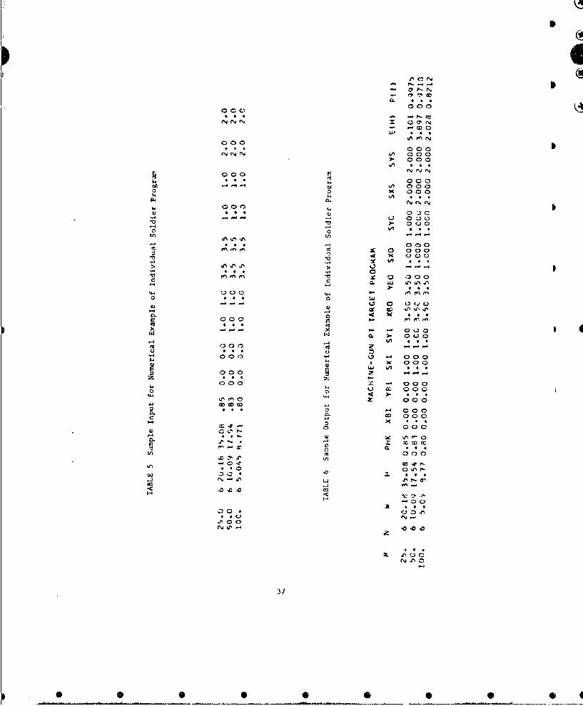
Three sample cases were run using the individual soldier program. Three
ranges were considered for one set of offsets and dispersions. Table 4 pre-
sents the input parameters for the three cases and Table 5 presents these
input parameters as they appeared on the input cards for the program. Table 6
presents the sample output for the numerical example.
*kaao phree O~rnnl c~cdr ru, i. t hia Ballsti -Jtau Lbr~
DRLESC computer. Total running time was .2 minutes while the compiling time
was .18 minutes. The memory required was 5K.
33
I

(U!cI
4)
* - 0
4) 1-4C, )
C) 1
04 0
*0 C
34S
B
S
Table 3 Dimension of Target(Rectangular Approximation)
Width HeightPosition (in.) (in.)
Standing 17.872 58.491
Kneeling 19.!00 33.874
Prone 26.C90 13.887 B
3
S
35
S
• • •• • •• •
I
j
Table 4 Input of Parameters for Numerical Exampleof Individual Soldier Program
Parameter Assumed Values
Range 25 50 100 H
Number of rds/burst 6
o 4•y1 1
a
Iy
X 3 ,0
Y3
X2 2
y2
Parameter Range()25 50 100
Width of target ($) 20.18 10.09 5.045
Height of target (P) 35.08 17.54 8.771
P(I/H) .85 .83 .80 p
36
p
SI••••
00000
NV 4 Nz I 0 r
of,0000
0 x- 000
u 0
0 00
fo 0* a 000
a) 00A
1&4 rn U 0 %*0 ) 0
di Q~ 0 000.
X000
*0
~0 coo)0
On m * 0 UJ
.-
C. 0. ~ 99A
a 000 r
9.. 37

L
4L sy-T 410-IU -IL iI'WIvIULJAL IJLu4 o ,k A'!L O'T. -7J.
Iti P kk - ý [.AMI'1.)I '1P I I, 4'Ub A 01L I I Y UF INCA!JAAý1 TA,1 4,\AI'tI ( ) , 11, r yt~ 'L I L f- N'i" I~ j HIT 1S d t ' U d ( I A MA Uil v U'4
C. k I A\ý o'41) 1 INI 1 Tlil CL\It i i %~St UF A %1146tt RL( IAN'.*
4 l t tI 0 1~ 'i U I K I U 0 1 LIN "A C I I I "d N ýCjI)O L ( Am S A ItIM N I;.3 11
c VU i I'- 11 k-J J .I CII( L I A t-,U S T h AS A H I GW-1 PRUt.46 t. I.I Y
C ril tu IiNG Il f 1 IAikt&I T HA4 ti-C Sut'SLrýU- .1 iPkt; .I LcSLCftH P 1 ,'gU t L I L (A I' U4 S 1l .)r1 tKuI-klf, AS A 61 VAR-
CI ATlL 4,1,1M ALI1,1 lJI1 I'i14T (ý IA A[ C VtN! ILAL I Y) OLI0flnlNATLý fl- CALH-
L 1' V.1', ]it A, (I- LSI I S J[ I I101t1 . 01'LP L NOLLN IL YN 1) Itiv IL),.AL S tL 1)1 vI-4 ý t- dsC5F1 1t1 V 1: R I IC..I .l I A NcLL -I. i( Jik I I1LCAM. t I% pr I'l L LJCA IL ) Al cI C : 4 - -3 AL it (F R t crA NG;L~
At I;l. v)1 J4 LN I ~i I P,((' J ýC T I L L , 1HAT 41LULHtr
.JSJ bL d,(S L I I. D1 I~ I' 1 ) 1' ,( fj 1 ~i.1 L
U UiN I UN 1L~2.( ~X
nKMI It i I I)1 f-UN'Ar I IIII 3U Ax IH MACHIN1. -1'"JN PT I( I C P1RG CAM'1/ I
R A I i~AI I H 'iw 1. 0 H ?l'xli I YLI %)XI SYI Ab LI VHLJ SAu 1YU sxS SY% L(H) P(I) /iH
I. L 0NSI AN S FuJ liA S I A'4 I 10P It (NT 1 1 14 11 Gf 4 1J JJ F 0k NU L ADA A I I^ Iu . ,o?' it.)3d ?,.), 1 1, .02 1 11I ? 4 hb 4 6 3 3 6 4 w,. 0b71 1 H43 i%ý1Gt
Ot-.'3h~ . /.3¶b2?J1,..3ILt19h4.n4772,td41
1 4C), . 23 1 44mt 2/. 1 >oi 4 I ),44kUH2 bdr .Uj4/Ith 969 i~2 , .09 131077)?1246 UV 12 -)3,1 1' 31., .,J'14 7? 1) it?7 5 ý41 .. 1 )0!1 707,,2;42 q . 064573Z ,),
L. I IPJ I LATA I A4i ii. - t~ 1 M Of(I., 01- TA~- I :F F sv. rS ANI) Di1SPCR S I(1 ~sC mu I ia I q~ I ko s~M UNw Irý
3 ýý.AD 5 a4 1-4 ,N, ,I iI PHK XUiIIyI ., S X I S Y I vX F 9y ýU tS X09S YL) IS XS pS YS4 FtiotMAr (! ..0q1 I '. , ¼ . 2 1 F' qIu. 3)
c IIR4 Tc ERM~ I I v I IN SU%'It I VALIIA It- P.kUI)At il- trY lA T \1 SUL.S&,CPKUJLLAi.F1- INCAi'ACI I Al ,S THI-. TI-r IPI.Si AMSAA TM NO 1,3 tkN 4.. 1
L I I ý P FL' I I I N4 S i 1 --,' P F . , E~A dL l v '14A 1 1 1Ei F 1 4S T l -d( JJ C I I L L
c iN 4tC I IT A , I i Iii 6I, ANI, \41 SIJbc1>-(..I-JI\ f . ,< JiC r I,. IN\CAiPActro, sc. PI 1 411601 PK ~1Fo (dI - J)SýS LGIJAS',)IA`4 !'4T1-(PATIUN WI TH- Ac ANU 6 - 41 - 11 , I M N.f-i I tV4' 4 .1
UN 'i K= I , 16
383
4 S S 5 lb
TXZCX*EBI.SXI*X(K I/SXO6TVZCY*Y6I+Sv fI*X(KI/SYOEXXR2EXAR*GIK I*EXPI-0.5*X(KJSX(K))*,IERFICX*w/2.O'-TXI-'EKF(-.CX*W/2.0 )1-TX))S
S EXYW.EXYR.G(K)*EXPE-O,5*X(I'I$*X(K)I*CERFICY*H-TVI-ERF(-TY))TwP Js3.1415921D0*2.0EXXRI=8.0*EXXR/DSQRT(TwPI IEXYRI'8.Q'EXYR. DSQRT(TWPI!PKF8-EXXR1*EXYR I
C IftN-1 I
C LOOP TO EVALUATE SUBSEQUENT TER;4S (I I TO N-I) IN SUM FUR PKSf6C AND PKFHi 1-4,1I - iSLS LJASIlA.' INTl (AATLI>J4 VI TH A - 4 AND .
00 8 I-I.M
C EVALUATES FACTORIALANSNFACI=I .0D0 6 IJZ1IlAhI=.E
6 FACI=FACI*(AN-AII/AI
SMSY=O .0SSMSX=O.OSMFX=O .0SMFY=O.0DO 7 Jm1Iv6X(J)=8.0*T(J.1-4.0
C PKSBSxs(XBL+XBOtSORTISX1#*Z4SXOt*2)tXIJ))ISXSSYs(YBI+YBO.SQ%&T(SYI**Z+SYO*#2,*XIJI)/SYSSUMXI=GIJ)*EXP(-0w%*X(J)*XIJ))*IERFI0.5*h/SXS-SXI-FRF(-0.5*W/SXS-~
1SX) )*S ISUIMYIsG(J3*EXPI-Q.5tX(J)*X(JI)tIERFIH/SYS-SY)-ERFI--SY))**I
*SMS:-S MSY:SIUJMY I
C PKFBTX=CXOXBI+SX I*X I.)/SXOTY=CY*YBI+SYI*XIJI /SYOSUMCX-SUMKI*( ERFICX*W/2.0-TX )-ERFI-CX#W/2;.O--T~ISU)MCYsSUMYI*(ERF(CY*I-I-YY)-ERF(-TY) 3SMFXrSMFX*SUMCX
7 SMFY*SMFYtSUMCY
C PKSBSMSKIS8.0*SMSX/OSQRTCTWPI)
S J45Y1=8.0*SMSY/USUHT(TWPI)PKSB=PKSBtFACI*I-PHK )**I*SMSXI*SNSYL
C PKFBSMFXlu8.O*SMFX/DSQRTITWPI ISMFY~i8.0*SMFY/DSQRT(TWPI I
8 PKFB=PKFB.FýCI*I-P11K I**I*SMFXI*SMFY[
C LND PKSB AND PKFB LOOPS
~39
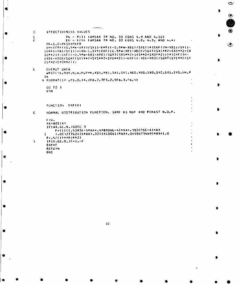
c EFFECTIVENLS¶, VALUES
C PK - PCI) (AMSAA TM NO. 33 EQNS 4.9 AND 4.10)(H - 1-(H) (AMSAA rM NO. 33 E-QNS 4.0, 4.3, AND '..4J
PK I .O-PKSB.PKFR
IERI-YLfS' Y1)2 (AN-1.OI*IERF((5,*B1-X(BO)/B)/QRTESxl'924SXS'?*2SX
*IYBL-YBO)/S0RT(SYt*s?,SYS**2.SYU)**21-EPF-((--Y81-YDD)#)SQRT(SYI*02+SYISO*2#SYO**2 ))
c cuTPuT UATA1t~Ib,69)RsNW,H.PHKXB1,Ye1,SX1,SYlXE0.YBOSXO,SYC,SXS4,SYSE~,p
9 FORHAT11H ,F5,.OI4,2F6.1',7F5.2,5F6.3,F6.41
GO TO 3C~NO
FuNCT 101, ERFXIX
c NO1MPAL DISTRIBUTION FUNCTION. SAME AS NUF AND FORAST N.D.F.
f 4*0.~AX-AS( X)IF(AX.GE.5.)GOTU 3
,.O0'1776263)*AX,.021141O06LJ*AX+.0498613469)*AX+1.0 *3 IF(X.GE.O. )F. 1.-F
ERF-FFtETUqNEN C
04

*
5*
5.2 Squad Model
1. Basic Description
The squad model is a Monto Carlo simulation of a weapon system engaging
an area target. The target configuration consists of a squad of man randomly
distributed within a rectangular region (Figure 1). The model provides .or
the region to be tilted to simulate various terrain slopes (i.e., level,
rolling, hilly, mountainous) and/or rotated to simulate various squad posi-
tions (i.e., line, column, oblique). The assumed technique of fire for any
weapon system considered in the simulation is to range-in initially and then
to sweep the rectangular region MS times, S
The measures of effectiveness for the squad model are T, the expected
fraction of casualties for MS sweeps of the rectangular region, and E(H)
the expected number of Lits for MS sweeps of the rectangular region. As com-
puted by the model, f and E(H) include both the effectiveness due to the
rounds fired during the ranging-in process and the effectiveness due to the
rounds fired during the sweep phase of the target engagement.
2. Assumptions in Modeling
The basic model assumed in this squad model is the two distribution
"shotgun" model which assumes that each round in a burst has the same prob-
ability of hitting the target. Therefore, no provision is made for the
first round in a burst to be distributed separately from the subsequent
rounds in the burst. This assuwption is valid for weapon systems fired from
rigid mounts (i.e., tripod or Pedestal mounts) and for low impulse (i.e.,
5.56mm as compared to 7.62mm or .50 cal) systems fired from any mount. This
41
*
* D•t 4}

r � +_ 5
* �•�jry�� <�: N- � �
-I � 0
V.t�
(d
K
- '� **�**�(��L ____
-.-------- �---------� A'
f�N�"
�
� �J
Z�§ �T.�'.A. �r _____
-�- -5�2TLii�Si4 r;, -�
K U'
_ .�
3
0 0 0 9 0 0 *

I
I
model also assumes that each round in a burst is distributed as a bivariate
normal with the horizontal (x) coordinate of each round distributed independ-
ently from the vertical (y) coordinate.I
The squad model, however, allows for several multiple projectile rounds
(e.g., multiple flechette rounds) to be fired at the target. Therefore,
since the "shotgun" model evaluates effectiveness values for ona burst of
rounds or one round with multiple projectiles fired at the target, a third
distribution had to be added to account for the extra multiple projectile
rounds in the burst. The three bVvariate normal distributions assumed in
the squad model areI
a. Distribution of the centers of impact of the bursts about the actual
aimpoint.
b. Distribution of the projectiles in a round about their center of
Impact. *c. Distribucion of the centers of impact of the rounds about their
center of impact.
Anothvi aiswaaption in this model is the assumed technique of fire, which
s t3 initially range-in and then to repeatedly sweep the rectangular region
a number of V.Lmes. The ranging-in procedure is as follows: The firer
estimates the range to some point (e.g., the center of the rectangular region).
This estimate il assumed to be
0 X 11q (2.1)
where o a standard deviation of the range estimation error (a percentage of
range estimation error times the true range) and
NRNI . a normal ranoum number.
43
*
• • • •• •
0.. . ........0 .° 0 0 *
0* 6
Wtith this procedure it ii possible for the firer to overestimate the range
to the center of the rectangular region as well as to underestimate it. The
firer then fires one multiple projectile round (one burst of rounds if 4
firing a nmachine gun) at this estimated r;.nge and checks to see if he has
ranged-in (assumed to be when the center of impact of thn projectiles has
lanided within the rectangular region). It is assumed that the firer can see* 6
where the projectiles land. If he is not ranged-in, thon the firer esti-
mates his miss distance (the distance from the center of impact of the
projectiles to the point in the region of which he is ranging-in), adjusts
his weapon to account for the miss distance and fires a second multiple pro- 4
jectile round (another burst of rounds if firing a machine gun). The esti-
mate of the miss distance is determinad.in a similar manner to the estimate
of the range only using the miss distance instead of the range, i.e., *a x NRN, (2.2)
where c - standard deviation of the miss distance (a pcrcentage of range
estimation error times the miss distance) arid
NRN - a normal random number (NRN does not necessarily equal NRN ).2 2 1
If the firer is not ranged-in with the second round (burst), he then estimates
his new miss distance, adjusts his weapon to account for this mwss distance 1 0
and fires a third round (burst). This procedure is continued until the firer
has ranged-in or when a predetermined number of rounds (bursts) hat bsen
fired.
After completion of the ranging-in process the sweep phase of the target
engagement begins. In this phase the firer sweeps across the rectangular
44 5
5 6
-- • --- ___ 0 * *

* q
region a predetermined number of times. The assumed technique of sweeping
is to fire, from the left of the rectangular region to the right., onc burst S I
of rounds at each of a fixed, predetermined number of equally spaced aim-
points. These aimpoints are assumed to be located along a line parallel to
the center line of the rectangular region and offset a distance from the
ranging-in point approximately equal to the firer's last estimated miss dis-
tance (determined from the ranging-in phase). Therefore, it is possible for
the line of aimpoints not to lie within the rectangular region. The location
of the first aimpoint from the left edge of the re';tangular region is given 5 6
as an inputrinto the program. HlGwever, with each Eweep the firer is allowed
some error in determining its location and,,fo in t.ae ranging-in phase, this
error is assumed to be * O *
PRe * NRN 3 * {YAl{ (2.3)
where PRE - percentage of range estimation error* 6
NRN3 - a normal random number
'IA1 - location of first aimpoint from the left edge of the
rectangulmr region (input into program).
Other asbumpdions used in this model are:
a. The rectangular region may be tilted to simulate various terrain
slopes (i.e., level, hilly, mountainous) and/cor rotated to simulate various
squad positions (i.e., line, column, oblique). 0
b. The mujzzle of the gun may be positioned above the ground to simulate
a weapon system mountsd on a vehicle.
45
• • •• Q ®• • • ¢D45

*
c. The individual men are each represented by a right circular cylinder
whose base is located on the ground plane. By the unique properties of a
right circular cylinder any plane through the center of the cylinder, when
viewed fro.. a line perpendicuLar to the cylinder, will appear as a vertical
rectangle. When e\valuating the hit probability of a weapon system, this
plane for each target is projected back until it is perpendicular to the line
of sight of Me firer. In this manner, regardless of the terrain slope, gun
height, etc. each man in ýhe squad will appear to the firer as a vertictJ
rectangle with a height equal to the cylinder height and with a width equal
to the cylinder diameter.
d. The individual men in the squad are uniformly distributed within the
rectangular region. The location of each man is determined at the start of
each replication and remains fixed throughout the replication (i.e., the man
do not change locations as the firer sweeps the rectangular region). All the
men tn the squad assume the same position (i.e., prone, standing or crouching)
and never change position during the replication or from replicaLion to
repl .cation.
e. The probability of incapacitation given a random hit P(I/H) is
assumed the same for each projectile in a round and for each man in the squad.
f. The measure of effectiveness against any individual man is P(I),
the probability of incapacitating a point target.
g. Closed form trajectory approximations are incorporated in the model
to account for the ballistic characteristics (ballistic coefficient. muzzle
velocity, drag data for the particular round, etc.) of the various rounds
considered. These equations are of the following form:6
46
• • •• • • •• Q 6
S
0
y - y+T +x tan u+T x ÷T3 x+T x'4+T x (2.4)
where
-O M height of muzzle of gun above the ground
)T } - set of coefficients (i-1, '. ,5)
x - range
a - angle of fire
y - ordinate of trajectory at range x with an angle of fire a
h. One replication of the Monte Carlo simulation consists of fixing the
locations of the men in the squad within thi rectangular region, firing a
number of rounds (bursts) to range-in (and hence, to determine the line of
fire for the sweep phase), sweeping the region with bursts of rounds and
finally calculating the fraction of the squad incapacitated and the expected
number of hits for that replication.
3. Basic Formulas S
AMSAA Technical Memorandum No. 33 presents a description of the selec£ion
of target locations, the geometry used in the simulation and the equations
required for the simulation (e.g., to determine the locations of the men and
aimpoints, intersections of the trajectories with the target planes, pro-
jections of the target planes, etc.).
A fourth coordinate sys'em has been added to the basic geometry of ANSAA
TM No. 33 and is described below[5].
Assume the muzzle of the weapor, located at the point (o, yo, 0) is
pointed at some point (x1, YI, ZI) after the weapon has bees zeroed in.
47
• • • •• • Q
I
0
lhcse two points dcturmniuc thl estimated lire-of-sight, the distance of
which, 1), is doternined by the equation
I'" ,.-1 1/2D , x + (y-v) ' 1/2 (3.1)
Vhe line-of-slght coordinate system is a right-handed rectangular Co-
ordinate syst r, one axis of which, the q axis, is coincident with the
line-of-sight. The crigin of the line-of-sight coordinate system is the
point (xl,ylzl). The r and s axes of this coordinate system form a plane
perpendicular to the line-of-sight. In this plane the point (qa ra'sa) is'a
selected, ,,hich represents the point the actual trajectory will pass through
(See Figure 2). This point is determined by the equations
qa " 0 (3.2)
ra - NRN O + 1,RN U3y (3.3)a ay 2 cy-
$a- NRN 3 ax + NRN k (3.4)
where NRNi (1-1,2,3. "--) are selected noxnal random numbers such that
-4 < NRN, < 4.
The point (qara sa) is located with respect to the firer at (xa 'ya Za).
The coordinates of this point are
Xa " cos, cosý q - sint cos, ra - sinq s5 + D cost cosý (3.5)
y - slot q. + COST r + D sinT - y1, (3.6) -yC -ln q- aot a
za - cost siný q - sint sinnt r + cosp sa + D cost sini (3.7)a a aa
48
6 6
* 0 0 0 0 0 * . 6
where the angles T and • are angles cf rotation and elevation respectively,
distinguishing the line-of-sight coordinate system (q,r,s) from the firer
coordinate system (x,y,z).
From Figure 2 it can be seen that
x- - D COST cosi (3.8)
yl , D sinT + y (3.9) S
z,- .L Cost siný, (3.10)
The coordinates of the point (x ,ya ,Za) can, therefore, be written as
xa . cost cos q - sinT cosJ ra - eini sa + x1 (3.11)
ya - inT qa + CosT r y (3.12)
za . OS siný q. sinT sini ra + cosVP s + z(3.13)
where the angles T and * are determined by
| l- yoT - arctan Y 0 (3.14)
(X2 + Z)/
and zI
p - arctan. (3.15)xI
Tht< line drawn from the origin of the firer coordinate system through
the projection of the point (o,r,s a) on the xz-plane, (xa,OZa ) is the u
axis of the trajectory coordinate cystem. The u axis can be considered to
be rotated from the x axis an angle X, where
zarctan .a (3.16)
a
-49
I
0 0 0 0 0 0

ILI4I
I I¢
4, C.
4 ,,
t) 5 4
I 5
>• 0
0
50
b •• •• 34 5
The point (xa,'YaZ a is located in the trajectory coordinate system at (ua'
VaWa), where
u - Cosx x + sinX z (3.17)a a a
Va " Ya (3.38)
w - -sinx x + cosx z - C0 (3.19)a a a
Effectiveness values Y and E(H) for the squad target are determined in the
following manner: f, expected fraction of casualties as a function of numoer 5
of rounds per aimpoint and number of sweeps per target engagement is cal-
culated by determining for each round fired the P(I), probability cf incap-
acitating a point target, for each individual man in the squad. Specifically,
£ is calculated in the following manner:
Let P(I)mjn be the probability of survival for the n individual tar-
get after m sweeps of the target engagement if j rounds are fired per
aimpo! nt. 5
m NA j(T) mjn n H 1 (l-P(I/H) t(H)k )N 0.20)
m - I ...... MSj - 1 ...... NRAn - i ...... ,NT
whereP(I/H) m. probability of incapacitation given a random hit
th
P(H).,... - probability of hitting the n target (man) when the ith
round is fired at the 1th aimpoiant during the k h sweep
NP - number of projectiles per round
NA - number of aimpoints per sweep
51 S
, @ • ®@ Q @S
4
C
MS - number of sweep'. per target engagement
NRA - number of rounds fired per aimpoint
NT - number cf individual targets
After each sweep of the rer.tangular region these values of P(I)mjn
are averaged over all individual targets to give P(I)mI the average pro-
bability of survival after m sweeps of the rectangular region as a
function of number of rounds fired per aimpoint, i.e.,
NT
( n-i ; "j i ...... MS- N- i .....1. ,NRA (3.21)
Values of P(I) mj are calculatel tor each replication, converted to
incapacitation prcbebilities and then finally averaged over replication to
give fmj, the expected fraction of casualties after m sweeps of the
rectangular region when j rounds per burst are fired per aimpoint, i.e.
NKLPf - I (I-P(I) Ij )/NREP .1......,DM (.2
J NR-l j - 1.. (3.22)
where NREP w number of replications used for the Monte Carlo simulation.
E(H)mj, the expected number of hits on the squad of men as a function
of number of rounds per aimpoint and number of sweeps per target engagement,
is calculated in a similar way to fm . That is,
NREP m NA j IE(H)mj "- E E E I NP * P(H)klin/NREP (3.23)
NR-l k-l 1-1 i-1 n-l
m ...... MS.- ,..-.. ,NRA
52
4b*
0... 0
Tmj and E(H)mj include the effectiveness due both to the rounds fired
during the ranging-in trocess and to -,t-a rounds fired during the sweep phase
of the ýarget engagement. For the ranging-in phase of the target engagementS
these effectieness values ara calculated in the same nanner as for the
sweep phase. However, during the ranging-in process values of P(I)
and r(H)mj are found for m-l, J-l and NA-the maximum number of rounds al-
loved for ranging-in.
4. Notation and Units of Input and Output
Table 1 presents the parameters required as input into the squad pro-
* gram and the proper format statements for each parameter. The following
notation was used in presenting the format statements:
Aw - alphanumeric field
Lw.d - real number with exponentI
Fw.d - real nuber without exponent S
1w - integer number
wherew - field width
Sd - nwmber of decimal places to the right of the decimal point
The trajectory card, which gives the coefficients oi the trajectory
equation for the round under evaluation, must be the first input card. All
* cases use these coefficients and, hence, only one round is evaluated per
run of the program. Each case requires two input cards. It should be noted
that the maximum values of lNT, NRA and MS given in Table I can be increased
y.. i "...... the arnrrj,,rlnrp dimension statements in the program,
53
S 4
0 •S •••• q

k2 ic 1 input Para7,eters !,r S;uad Program
(2 cart!/case and 1 trajectory carti
Sv_.mb l Pararncter Units Colomns Format-
trajecoy Card
-. 1-15 E15,3
T(2) Coefficien,.s of round's - 16-30 E15.3
T(3) trajectory equ ition - 31-45 E15.3
1(4) - 46-60 E15.3
T(5) - 61-75 E15.3 S
W Round identification - 76-80 A5
Card 1 S
NREP Number of replicatious/target - 1-5 15
engagement
NT Number of man in the squad (<100) - 6-9 14
MZ Maximum number of rounds allowed - 10-13 14
to range-in
NRA Number of rounds/aim point ( 20, - 14-17 14
ANP Number of projectiles/round - 18-24 17.2
G PRE Component of standard deviaaLvu of mnterr 25-31 F7;2
range estimation error, a (a - PRE
x range)
YO Height of muzzle of gun above maters 32-38 F7.2
ground
RW Depth of rectangular region meters 39-45 F7.2
RL Length of rectangular region meters 46-52 F7.2
Th Angle theta (e) radians 53-59 F7.2
PH Angle phi (ý) radians 60-66
SWM Width of individual man meters 67-73 F7.2
HM Height of individual oan meters 74-80 F7.2
• 54
* 0 D 0 0 0 0 *

.2/
Table I Input Parameters for Squad Program (Cant)
(7 cards/case and 1 trajectory card)
Symbol Parameter Units Columns Format
Card 2
MS Number of sweeps ('50) 1-4 14
NA Number of aimpoints 5-8 14
DA Distance between aimpoints meters 9-14 F6.2
AZ (a,y) coordinates of ranging-in meters 15-20 F6.2
GZ poi.it (relative to center of meters 21-26 F6.2
rectangular region)
GAI y coordinate of first aimpoint meters 27-32 F6.2
(relative to center of
rectangular region)
XR Range from weapon to center of meters 33-38 F6.2 *rectangular region
SAX mils 39-44 F6.2a
x
SAY 0 mils 45-50 F6.2a
SCX a mils 51-56 F6.2c
x
aCY mils 57-62 F6.2cy
SPX a mils 63-68 F6.2Px
SPY a mils 69-74 F6.2P.
PHK P(I/H) - 75-80 F6.2
55
0 0 0 0 0 0 0 0 0
4®
An explanation of sorme oi the parameters and procedures for obtaining
4 some of the parameters are given as follows.
For NRA rounds per burst and NP projectiles per round the horizontal
(x) and vertical (y) dispersions (standard deviations) for the three distri-
butions required in the squad model are as follows:
(Oa 0 a Total delivery error (standard deviarton of the centersa Y of impac: of the NRA round bursts about the actual aim-
point. It should be remembered that the locations of4 the actual and theoretical Pimpoints are both daternined
in the simulation and vary from sweep to sweep and from
replicarioa to i nlicaticn).
(Oco ) - Round to round dispersion within a burst (standard devi-
"" y ation of the centers of impact of the NRA rounds in aburst about their center of impact, i.e., the center of
impact of the burst). *(0 to ) - Individual projectile dispersion within a round (standard
x y deviation of the NP projectiles in a round about theircenter of imcact, i.e., the center of impact'of the round).
Figure 3 is a diagram of these dispersions,
Values of SCX and SCY are obtained from SPX and SPY respectively as
s4 s__- SPX ScY- SP-
However, if the squad model is to be used to evaluate the effectiveness of a
* machine gun enga:L&g :n =m tarlet then
1. NRA - 1 (i.e., one burst per aimpoint)
2. ANP - number of rounds per burst
3. SCX - SCY - 0 mils (this dispersion exists only when more than one4
irultiple projectile round is fired per aimpoint).
56
'4
1%D
I
4I
I
Qe
U. 0
'CQ'S
b .'\
/ 0 I457L
I..
• • • •I e • !
Figure 4 is a dlVagran of the rectangular region as seen from a 1lne S
perpendicular to the 4,, plane. Included in Figure 4 are the ay co-
ordinates axes, a line of ainpoints and a location of the first airrpoint,
The number of aimpoints in each sweep is generally assumed to be a function
of the individual projectile dispersion, opx and range, i.e., a procedurep x
for obtaining the maximum number of aimpoints allowed per sweep, MA, is
RI.MA - 4P4*SPX
where SPX is in meters.
This procedure allows for overlapping burstn of radius 4 o and hence,px
maximum coverage of the length of the recc-ngular area. It is not necessary
that the number of aimpoints used in the sqGad program be 11A.! procedure
for ob:aining DA, the distance between the aimpoints is
DA - R L NA MANA
and GAI, the coordinate of the first aimpoint is
,,I -RL + DAUn, - -2- _ T2 2a
0 is the oblique angle of the rectangular region relative to the gun
and characterixes the position of the squad. For example, if 0 - 0* then
the squad Af men is a linear target while if 0 - 108 then the squad of S
men is a linear target with depth.
t is the slope of the rectangular region. For example, if * -
then the terrain is flat, while it I - 0"• the terrain is hilly.
58
*
* I
* g
0* 4
* 4
* 4
© I0•
4)• •
© a__ m .;-" - -, -. el
*0 S
• Q•Q Q••0
Ajsunel value, t'or the depth and length of the rectangular regiQn for
an assaulting enemy squad are 10'1 and 50M, respectively, and for a defending
enemy squad, 20X and 1CC>., respectively. Values for the width and height
of the rcctai,gular approxima:ions of the individual men in the squad as a
function of the positian of the men are given in Table 2.
Table 2 Dimensions of Indivinual Men(Raetangular Approximation)
Width Height(in.) (in.)
Standing 17.872 58.491
Kneeling 19.500 33.874
Prone 26.000 13.887
The output for the squad program includes many of the input parameters, *and the average effectiveness values, f ind E(R), as a function of number of
rounds per aimpoint and number of sweeps per target engagement. These values
include the effectiveness due to the ranging-in process. Also given are the
average number of rounds (bursts it evaluating a machine gun) required Lu 4 C
range-in and 7 and E(H) for the ranging-in process.
5. Numerical Example
Two sample cases were run using the squad program. For this example it 4
was assumed that a vehicle mounted machine gun firing 6 round bursts was
engaging an assaulting enemy squad of 10 men at each of two ranges. The
----------------------------------------------------------- fioned on flat terrain. Table
60
I C

4ICA
S
3 presents the .nput pracmetef; for the two cases and Table 4 pcesents these
input parameters as they ap;:ared on tlhe inurt cardg for the program. Tab)e>
5 presents the sample outpuit for the numerical example.
These two sanpie cLses were run on Ballisitic Research Laboratory's
BRLES, compucur. Total running time was 6.52 minutes while the comnili'
time was .46 minutes. The memory required vas 10K.
SS
61
• • • •• Q •

4
1 ibt . I ip ut !'nI ýi: rtot rs Ior Numcert.cal Example of Squad Program
Parimcitur Ass -med Values
- .42111926E-2Couticict-t of rFundb - .6539,505E-5IralcLtoty tql.it1.on - .27588514E-8
0.OEO- .62596806E-15
Round ldentilication 5
N. or replicatins 50
No. i ::iein in squad 10
Xax, no ot rangitra-in rounds 5
No. of rounds/ainpoint 1No. ft Projectiles/round 6
Component of st..ndard deviation of .25
range ostirnatiQon error
Depth of rtuangular region 1Cm
Length of rtctangular region 50m
Angle I 1 0 radAngle ý 0 rad
Width rf 'an .495mHeight of man .861m
No. of sweeps luiNo. of aimpoinzs 15
Distance between aimpoints 3.333m
a coordinate of ranging-in point 0 m
y coordinate of ranging-in point 0 my coordinate of first aimpoinc - 23.33mRange 50 100ma
&y 016
C x'C0
C
P x
P.,
P(I/H) at 50m .83P(I/H) at lOOm .80 r
62
L•
S
r - r - C
�9 9
A�00 Sut' *r *
LjJ O - C --04- 4-
C-0 0 00� *A 0� o -
U NC C'14 0'o C� I SI-I . .
C. C C-'I C 01W 0 0:3 9 90' o
(/3 9 9
44 0 0 C0
L-.JC Z0.
0. *c0C�CH Z�t' SL/%
- �,0 C* I .090ci i�0 *C
4� -4-4
14 -
2 �L/3* .r'
.n .0 .014 PNtANC0
944 N -
:3 .- '0.0 aN *'N'-4
* . n� .LI iii N N S.4 u a
to ro *Cc� .0 .0fv,'o �o-t IC'
* 4.'-.4 0 0A I *C -�-0
0-N
IC' M U' �',� .n mIN 9 9
r' rn-o 0'0.4 U.' 4 1%
N-to C S
* 'A 0 IC' 0I -4 -
63 S
S
I*�.�±.__ * �

Table 5 Sample Output for Numerical Example of
Squad Program
,4114tHk (IF MEN IN SQUAD = 10
WInIH :)F MAN 0.49,90 HEIGH1 OF MAN = 0.861M
WIPTit [it RLIUIN 1O.O0M LENGTH OF REGIUN = 50.OOM
•LUAU Fo-kNAIIIJN = 0.0 RAQ TERRAIN SLOOE = 0.0 RAD
Mu/ZLt HEIGHT = 2.r500M
N(UMBER OF REPLICATIONS = so
HLIRI Z Ot-LIV(RY ERkr)R = 1.OOMILS VERI DELIVERY ERROR .]OOMILS
HnRIZ PROJ f1SPLRSIjrv = 1.00MILS VFERT PROJ DISPERSIUN 1 j.OOMILS
RANGING-IN PHASt-
NUMBER OF RURSTS .,LLEjUIREL, = 1.8.B E(H) = 0.6U FBAR a 0.008
SWEEP PHASE
RANGE P1I/HI 10 O(f NO ROSW NO PROJ/ NO OF E(H) FBAK
(M) AiM PIS AIM PT ROUNID SWEEPS
50. 0.830 1, 1 6. 1 5.34 0.127
50. U.8•o0 1' 1 6. 2 9.94 0.212
150. 0.830 15 1 6. 3 13.47 0.261
50. 0.830 15 1 6. 4 18.62 0.340
50. 0.830 1"• 1 6. 5 2 2.91 0.397
50. 0.830 15 1 6. 6 2b.4 0.434
5O. 0.830 i5 /6 1 31.15 0.474
50. 0.830 15 1 6. 8 35.35 0.5)5
50. 0.830 1t ) 6. 9 40.0a 0.525
50. 0.830 ILI L 6. 10 44.48 0.556
64
aI
0 0 0
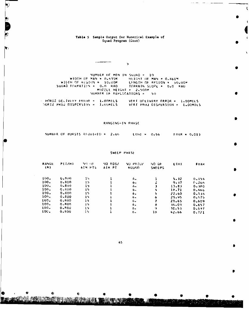
Table 5 Sample Output for Numerical Example ofSquad Program (Cant)
NUM13ER ()F MEN IN SUUlAD LOIIwIOTH OF MAN 0.95 H*ýq -)IfHT (IF MAN =0.861M
WILrfH OlF RiC.1IIN 10.00M LF-NGTH OF RFGION a ).UOOSQJUAD F('RHATIC-N 0 .0 RAO TFRRAIN SLOPE 0.0 RAO
mIJZZLk HEIGHT =2 .,,onmNdUMBEFR (IF- REPJLICATIOJNS - 50
HOIRAZ OEL IV)R L- RRIIR = I.00MILS VERT OFLIVERY FRROR - .0OMILS>OiRII P'RL)J flISPERý)1fi' = 1.OOMILS VFRr PRO~j DISPERSION =L.OOMILS
RANGING-IN PHASE
NUMBER OF BURSTS RfkoUitdt = 2.6b EIIH) =0.56 FBiR =0.013
SWEEP PHASE
RANGE PUI/H) N'4) -it 14 ROW/ NO PROJ/ ?40 UI E(H) FbARIM) AItM PTS AIM P-1 ROjUNDr SWEEPS
100. U.Sfon V, 1 6. 1 15.12 0.154100. 0.800 LI, 1 6. 9.371 -. 6too. 0.80o 11P 1 6. 3 13.83 0.0,0100. 0.H030 11) 1 b. 4 IF.71 0.4bb100. 0.800 is 1 6. 5 22.60 0.536100. 0.800 11 b1 6 25.95 017100. 0.800 15 1 .7 29.65 0.609i 01) e .O 1)80 6. 8 $4.09 0.657100. 0.800 15 6. 9 38.53 0.6q710Q.. 0.8010 1. 1) 6. 1.0 42.66 0.721
65
4F 411 lull
YS

It
iJs CLiG R6DELS',KP-29,T :MEU4B0CC SY-TNLO-70 5.2 SQUAD MOD-L OCT.-10
CC THE SOD MODEL IS A MONTE Z-KLO SIMULATION OF A WPN SYSTEM ENGAGINGC A SQUAD OF MEN RANDOMLY DISTRiBUTED WITHIN A RECTANGULAR REGION.C MEASURES OF EFFECTIVENESS ARE FBAR, THE EXPECTED FRACTION OF
C CASUALTIES AFTER MS SWEEPS OF THE RECT REGION, AND E(HI), THEC EXPECTED NO OF HITS PER TGT ENGAGEMENT AFTER MS SWEEPS OF THEC RECTANGULAR REGION.C ASSUMPTIONSC A THREE DISTRIBUTION SHOTGUN MODEL (REF - AMSAA IT NO 331C EACH PROJECTILE IN A ROUND (EACH ROUNP IN A BURST IFC MACHINE GUN FIRE) HAS THE SAME PROBAB OF HITTING TGT
C EACH ROUND IN A BURST HAS BIVARIATE NORMAL DISTRIBUTIONC HORIZONrAL IX) AND VERTICAL (Y) COORDINATES OF EACHC ROUND ARE DISTRIBUTED INDEPENDENTLY 0
C INDIVIDUAL MEN IN SQUAD ARE REPRESENTED BY RIGHT CIRCULARC CYLINDERS AND ARE UNIFORMLY DISTRIBUTED WITHIN THEC RECTANGULAR REGIONC TECHNIQUE OF FIRE IS TO RANGE-IN INITIALLY AND THEN TO
C REPEATEDLY SWEEP THE RECTANGULAR REGIONC MEASURE OF EFFECTIVENESS AGAINST ANY INDIVIDUAL MAN IS
C PIll, THE PROBABILITY OF INCAPACITATING A RECT PT TGT pC USES CLOSED-FORM TRAJECTORY APPPROXIMATIONS
DIMENSION AT(IOOItGrtiOOleTIS|IEHIZO),P(2Oe•10tTEH(205OO)DIMENSION TFBAR(20t5O
C INPUT DATAREADIStl(TtIIlIIt5),W
I FORMATISEI53,A5)2 REAO(5,3)NREPNTMZNRAANPPRE,YO.RWRLTHPH,WMNHM3 FCRMAT(15.'.°, -..-.
READIS,(4)NSNADAtAZGZGA1,XRSAXSAYSCXSCYSPX.SPYPHX4 FORMAT(214,12F6.2Z
I10ERZNO.OEHZSO.OFRARZsO.ORNuNREPTN-NT005 M5IMS00 5 JuI.NRATEH(JM)4O.OT I ruJ, -!.
STHuSIN(TH)CIHaCOS(THISPH-SIN(PHi
CPH*COSIPH)
C Y - COORDINATE OF CENTER W- RECTANGULAR REG ONYR0.5*RW*SPH
SC NUMBER OF REPLICATIONS (FOR MONTE CARLO) LOOPC0 28 NRmTLNREPSPZ'0.O
66
p
C 0 0 0 00
4 S
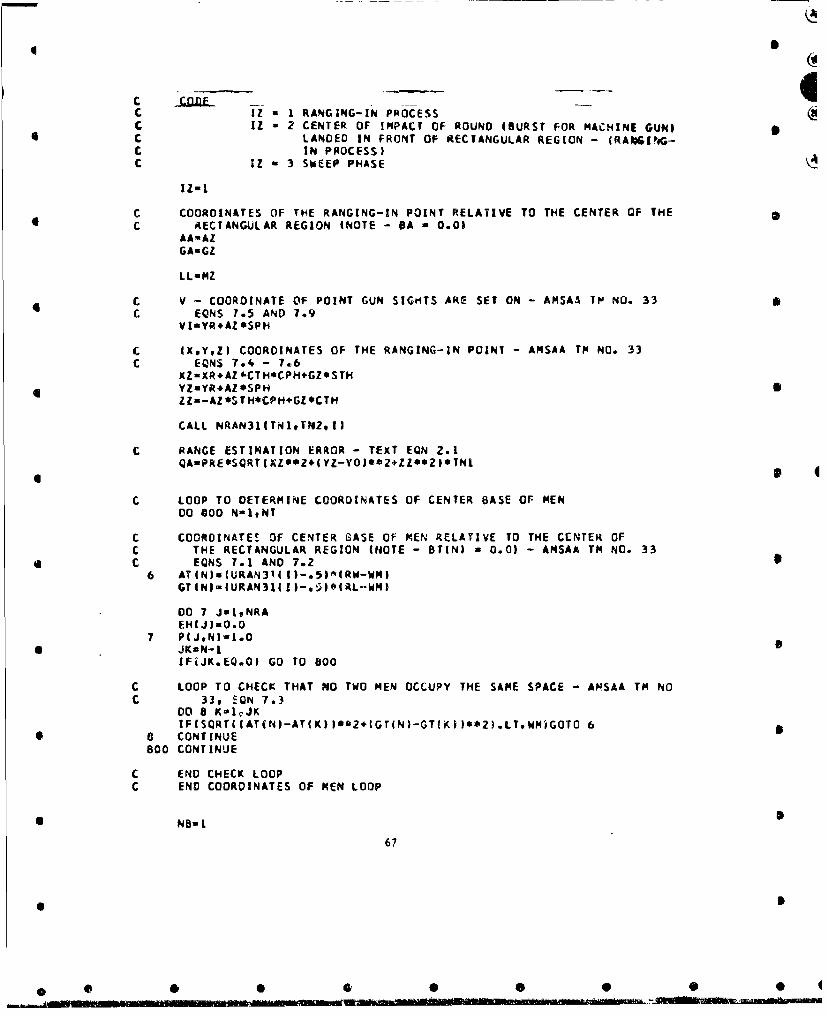
C IZ a I RANGING-IN PROCESSC IZ - 2 CENTER OF IMPACT OF ROUND 4BURST FOR MACHINE GUN) 5C LANDED IN FRONT OF RECTANGULAR REGION - (RANI,6G-C IN PROCESS)C IZ - 3 SWEEP PHASE
IZml
C COORDINATES OF THE RANGING-IN POINT RELATIVE TO THE CENTER OF THEC RECTANGULAR REGION (NOTE - BA - 0.01
AAmAZGA=GZ
LL=MZ
C V - COORDINATE OF POINT GUN SIGHTS ARE SET ON - AMSAA TM NO. 33C EONS 7.5 AND 7.9
VI-YR*AZ*SPH
C EXYZ) COORDINATES OF THE RANGING-IN POINT - AMSAA TP NO. 33C EONS 7.4 - 7.6
XZ-XR+AZ*CTH*CPHeGZOSTH4 YZmYR*AZ*SPH S
ZZJ-AZ*STH*CPHeGZOCTH
CALL NRAN3l(TNIqrN2oI|
C RANGE ESTIMATION ERROR - TEXT EON 2.1QA-PRE*SQRT(XZ*024(YZ-YOI**2+ZZO*21*TNI
C LOOP TO DETERMINE COORDINATES OF CENTER BASE OF MEN00 000 N-ItNT
C COORDINATES OF CENTER GASE OF MEN RELATIVE TO THE CENTER OFC THE RECTANGULAR REGION (NOTE - BT(N) - 0.01 - AMSAA TM NO. 33C EONS 7.1 AND 7.2
6 ATlN)w(URAN31.(I)-.5lw(RW-WM-GTlNl-lURAN314I1-*t.el(RL"-WM)
00 7 JistNRAEH(J-=O.O
7 P(JgN -I•.O* JKmN-1 S
IFiJK.EQ.O) GO TO 800
C LOOP TO CHECK THAT NO TWO MEN OCCUPY THE SAME SPACE - ANSAA TM NOC 33t EQN 7.3
DO 8 KmIQJKIF(SQRT(IAT(N)-AT(K) )*r2÷(GT(N)-GT(KJ)**2).LT.WMiGOTO 6
* CONTINUE800 CONTINUE
C END CHECK LOOPC END COORDINATES OF MEN LOOP
NB-=
67
0 5
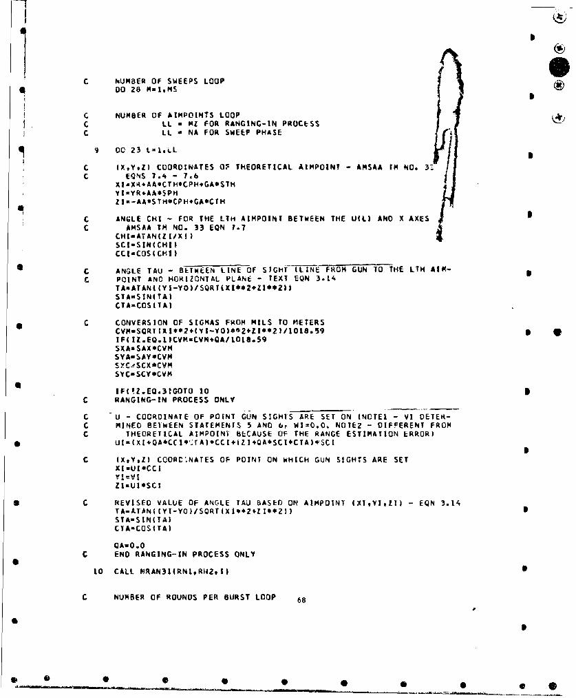
C NUMBER OF SWEEPS LOOPC,00 Z8 malMs
C NUMBER OF &IMPOINTS LOOPC LL m MI FOR RANGING-IN PROCESSC LL a NA FOR SWEEP PHASE
C (X,V.Z) COORDINATES OF THEORETICAL AIMPOINT -AMSAA rm NO. 0023-iL 7Y t-YR.AA*SPHZ ia-AA*STH*CPH-+GA*CTH
C ANGLE CHI - FOR THE TIM AIMPOINT BETWEEN THE U(L) AND X AXESC AMSAA TM Na. 33 EQN 7.7
CHI-ATANIZI/Xi)SCISSIN(CHIICC 1-COS ICMIl
C ANGLE TAU - BETWEEN LINE OF SIGHT (LINE FROM GUN TO THE LTH AIR-C POINT AND HORIZONTAL PLANE TEXT EQN 3.14
TAnATANIIY I-YO)/SQRT(XI**24ZI**2Z)ST AlS INITA)CIA-COSI TA)
C CONVERSION OF SIGMAS FROM MILS TO METERSS ~CVM=SQRTIXl**2.(YI-YOT'*2GLI**2I/1O18.59 *
IPI IZ.Egl)CVM=CVM*QA/l0tS.5qSXAsSAX*CVMSYA-SAY*CVM
syC-SCy*CVm
IF(!Z.EQ.31GOTO 10C RANGING-IN PROCESS ONLY
C U - COORDINATE OF POINT GUN SIGHTS ARE SET ON (NOTEI -VI DETER-C MINED BET'WEEN STATEMENTS 5 AND 6, WI=lO.0, NOTEZ - DIFFERENT FROMC. THEORETICAL AIMPOINT BECAUSE OF THE RANGE ESTIMATION ERROR)
* ~UI-(XI.QA*CC I*'AAI*CCI4(Z 140A*SCI*CTA)*SCI
C (XtYtZ) COORD',NATES OF POINT ON WHICH GUN SIGHTS ARE SETXIMUI*CCIYevI %,
ZI-U1*SCI
*C R~EVISED VALUE OF ANG-LE TAUl BASED ON AIMPOINT 4XI,YltT - EQN 3.14TA-ATAN((YI-YO'I/SQRTxIX.*Z+iI**,)ISTA- SIN T ATC TA-COS(ITA)
QA-0.0C END RANGING-IN PROCESS ONLY
10 CALL MRAN31(RN1.R"2911 6
C NUMBER OF ROUNDS PER BURST LOOP 68
*~4 S A00
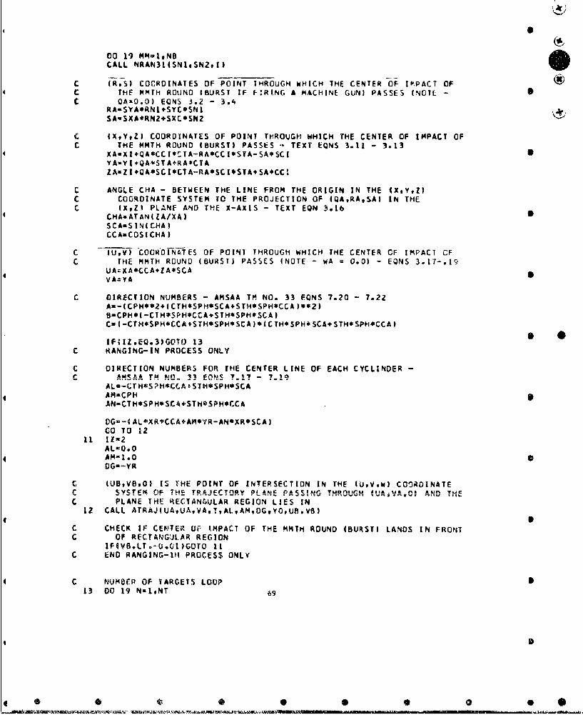
00 19 MM-1,NBCALL NRAN31(SN1,SN29I)
C (R,S) COCORINATES OF POINT THROUGH WHICH THE CENTER OF IP;PACT OFc THE MMTH ROUND (BURST IF f-RING A MACHINE GUN) PASSES I-NOTEC OAnO.0) EONS 3.2 -3.
RA-SYAORNI.SYC*SN ISA*SXA*RNZ.SXC*SN2
c IXtY*Zl COORDINATES OF POINT THROUGH WHICH THE CENTER OF IMPACT OFC THE MMTH ROUND IBURST) PASSES - TEXT EQNS 3.11 - 3.13
4 XASXIQA*CCI*CTA-RA*CCI*STA-SA*SCIVA-YE +QA*STA,ýRA*CTAZA-ZR QA*SCI*CTA.-IA*SCI*STA+SA*CCI.
C ANGLE CHA - BETWEEN THE LINE FROM THE ORIGIN TN THE 4xtYtz)C COORDINATE SYSTEM TO THE PROJECTION OF (gA,RA,SAI IN THEC (XZ) PLANE AND THE X-AXIS - TEXT EON 3.16
CHA-ATAN(ZA/XA)SCA=S INI C'HA)CC AC OS ICHA I
C --7iU,) cooRDf-INAT-ES OF POINT THROUGH WHICH THE CENTER OF IMPACT CFC THE MMTH ROUND (BURST) PASSES (NOTE - WA =0.0) - EQNS 3.17-.19
UA=XA*CCA+ZA*SCAVA=YA
C DIRECTION NUMBERS - AMSAA TM NO. 33 EONS 7.20 - 7.22AS--CPH**2,4CTH*SPH*SCASTHOSPH*CCA [s*ZIB-CPH*(-CIH*SPH*Cf-A*STHaSPH*SCA 3CI(-CTH*SPH*CCA+STHSSPH*SCA )*(CTH*SPH*SCAi+STH*SPH*CCA I
IF(IZ.EQ.3lG0T(J 13C RANGING-IN PROCESS ONLY
C DIRECTION NUMBERS FOR THE CENTER LINE OF EACH CYCLINDER -CAMSAA TM NO-l 33 EONS~ 7.1 - 71
AL*-CT H*S?H*CC.A STH*SPH*SCA4 ~AMzCPH
AN-CTH'SPH*SCA+STHOSPH*CCA
D)G--4 AL*9XRIPCCA+AM*YR-ANSXR*SCA ICO TO 12
11 11=2ALO0.OAM-1.0DG--YR
c (UBVBv0) IS YHE POINT OF INTERSECTION IN THE IUV,W) COORDINATEc SYSTEM OF THE TRAIECTflDV PLANE~ PSStG THROUGHU !UAjVA#0 AND TH
C PLANE THE RECTANGULAR REGION LIES IN12 CALL ATRAJtUAUA.VA. TALAM,OGYOUBVB)
C CHECK IF CENTER OF XMPAC7 OF THE MMTH ROUND IBURST) LANDS IN FRONTC OF REC!ANGliLAR REGION
IFEVO.L.T.-O.Cl)GOTO 11C END RANGING-Vi PROCESS ONLY
4C NUMBER OF TARGETS LOOP13 00 19 NmlNT 69
*D

U C-0.0
4 CLO0.O
CNmO.OBT*O.000 16 JJ01,2
C (U,V,W) COORDINATES OF THE CENTER BASE AND CENTER TOP OF THE NT"I4C CYLINDER -EONS 7.11 - 7.13 AND 7.26 - 7.28
C IJ I CENTER BASEC JJ -2 CENTER TOP
UTa(XR.ATIN*CTH*CPH-8TOCTH*SPH4GT(NI*STHIeCCA4DI i-AT (N)*ST.ii*CPH.DT*STH*SPH.GT4N)*CTHI.SCAVT*YR*AT IN)*SPH.IBT*CPHWTa-(XR*AT(NI*CTH*CPH-BT.CrH*SPHGT(NI.STH)*SCA+
4 li-AT(N)*STH*CPH.&T*STH*SPHGT4N)*CTH).CCA
GOTO( 14.I5)JJ14 DTo-iA*UTB*VT+C*WT)
C, 4UPvP,0) IS THE POINT OF 14TERSECTION IN THE (UV*Wl COORDINATE4C SYSTEM OF THE TRAJECTORY PLANE PASSING THROUGH (UA,VA,O)
C AND THE TARGET PLANE THROUGH THE NTH TARGETCALLAtRAJ(UT,UA,VA.I.A.B.DI.YOUPI,VPI
C CONVERSION OF SIGMAS FROM MILS TO METERSCVM-SQRT(UP**2+(VP-YO)**2)/I1B1.59SXpsSPX*CVM
4 SYP-SPY*CVM *C, CHECK IF CENTER OF IMPACT OF ROUND (OURSTI IS GREATER THANC 4*SPX FROM THE NTH TARGET. IF YES THEN ASSUME SURVIVALC PROBABILITY FOR THE NTH TARGET IS 1.0
D)MAX.4ý(fl*PW4;ORTf U*,IvT-v oslo iIt A11Re8digIF(ABS(WT l-WM/2.O.GT.0MAX)G0TD 17
D5N-(UP **2. VP* (VP-YD) I
C I-TU.V) ARE THE COU-RDINATES IN- THE (U*V,W) COORDINATE SYSTEM CiF TiHEC CENTER BASE AND CENTER TOP OF THE f.TH CYLINDE~R (MAN) PROJECTEDC INTO THE PLANE PERPENDICULAR To THE LINE OF SIGHTC JJ a 1 CENTER BASE
4 C JJ - 2 CkNrER TOP15 CALL ATRAJ(UT,U)TPVTTUPVP-YQOrSYOtU,V)
UC-UC+.5*U
wCaWC*.5*WTC-Lo-CL+
4 C"--CM+VCN--CN~+wT
16 OTW14M
C, END OF NUMBER OF TARGETS LOOP
4 C PROJECTED HEIGHT OF THE NTH TARGET -AMSAA TM NO. 33 EON 7.30HPM-SQRT (CL**Z*CM**2.CNs'.2)
70
40 0

S
C OFFSET OF (UPoVP,0) FROM PROJECTED CENTER IUC@VC-,WC) OF THE NTHC TARGET - AMSAA TM NO. 33 EQNS 7,31 AND 7o32
YBAR ICLe(UP-UC)÷CM*(VP-VC)-CN*WC)/HPMXBAR-SQRTI (UC-UPI**2,(VC-VPI**2,WC**2-YBAR**2| ()IF(WC.GT0O,0)X8ARo-XBAR
C P(H) - PROBABILITY OF HITTING THE NTH TARGETH-IERF((.5$WM-XBAR)/SXPI-ERF(I-.5kM-XBAR)/SXPI)*
l|ERF(I.5*HPM-YBAR)/SYPI-ERF((-.5oHPM-YBAR)/SYPI)
C SURVIVAL PROBABILITY FOR THE NTH TARGET - TEXT EQN 30ZOSP=I1.O-PHK*H)**ANP
GO TO 1817 SPsI.0
HuO.O18 DO 19 J=MMvNRA
C SURVIVAL PROBABILITY AND EXPECTED NUMBER OF HITS FOR EACH SC COMBINATION OF NUMBER OF ROUNDS PER AIMPOINT AND TARGETC TEXT EONS 3.20 AND 3.23
EHIJI-EH(J)+ANP*H19 PIJN)-PiJN)*SP
C END OF NUMBER OF ROUNDS PER BURST LOOP
G0T0f20c21,221l.ZC RANGING-IN PROCESS ONLY
C COORDINATES RELATIVE TO CENTER OF RECTANGULAR REGION OF THEC POINT OF INTERSECTION OF THE TRAJECTORY AND THE PLANE INC WHICH THE REGION LIES
20 AB=IUB*CTH*CCA-UBSTH*SCA-XR*CTH)eCPH÷SPH*(VB-YRtGB=UB*STH*CCA*UB*CTM*SCA-XR*STH
C CHECK IF CENTER OF IMPACT OF ROUND IBURST) LIES WITHINC RECTANGULAR REGION (CRITERION FOR RANGING-IN PROCESS)
IFI-RW/Z.O.LE.AB.AND.AB.LE.RW/2.O.AND.-RL/2.O.LE.GBI.AND.GB.LE.RL/2.OIGOTO 24
C (XtYtZI COORDINATES OF THE POINT OF INTERSECTION OF THE TRAJECTORYC AND THE PLANE IN WHICH THE REGION LIES
21 XB=UB*CCAYB.sVBZB-UB*SCA
CALL NRAN31I(TNIsTNZtl)
C ESTIMATE OF MISS DISTANCE IDISTANCE FROM RANGING-IN POINT TGC WHERE CENTER OF IMPACT OF ROUND (BURST) LANDED) - TEXT EQN 2.2
QA=PREOSQRT(IXZ-XB)**2.iYZ-YB)**Z(ZZ-ZB)**2)*TNI
GO TO 23C END RANGING-IN PROCESS ONLY
C COORDINATE OF AIMPOINT (L.I) RELATIVE TO CENTER OF RECTANGULARC REGION (NOTE - AA DETERMINED DURING RANGING-IN PRUCESS (BETWEENC STATEMENTS 24 AND 25)t 6A - 0.0)
22 GA*GA*DA 71
0S
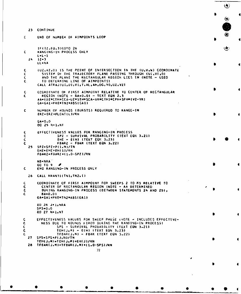
b
23 CONTINUE
C END OF NUMBER OF AIMPOINTS LOOP
IFIIZ.EQ.3)GOTO 26C RANGING-IN PROCESS ONLY
LmL-124 IZ=3
LLmNA
C (ULVZvO) IS THE POINT OF INrERSECTION IN THE (UVtW) CCORDINATEC SYSTEM OF THE TRAJECTORY PLANE PASSING THROUGH (UiVI.O)C AND THE PLANE THE RECTANGULAR REGION LIES IN (NOTE - USEDC TO DETERMINE LINE OF AIMPOINTS)
CALL ATRAJ(UI ,UIVI TtALAhPDGYOUZVZI
C CCURDINATE OF FIRST AIMPOINT RELATIVE TO CENTER OF RECTANGULARC REGION INOTE - BAmO.O) - TEXT EQN 2.3
AA=(UZ*CTH*CCA-UZ*STH*SCA-XR*CTHI*CPH+SPH*(VZ-YRIGA-GAI+PRE*TN2*ABSIGAII
C NUMBER OF ROUNDS (BURSTS) REQUIRED TO RANGE-INERZ-ERZ+FLOAT(LI/RN
QA=O.ODO 25 N=1.NT
C EFFECTIVENESS VALUES FOR RANGING-IN PROCESSC SPZ - SURVIVAL PROBABILITY (TEXT EQN 3.21)C EHZ - E(HI ITEXT EQP' 3.23) S 0C FBARZ - FBAR (TEXT EQN 3.221
25 SPZ=SPZeP(IN)/TNEHZaEHZ+EHI I /RNFBARZsFBARZ+(I.O-SPZI/RN
NBmNRAGO TO 9
C END RANGING-IN PROCESS ONLY
26 CALL NRAN31ITNIvTN2.I)
C COORDINATE OF FIRST AIMPOINT FOR SWEEPS 2 TO MS RELATIVE TOC CENTER OF RECTANGULAR REGION (NOTE - AA DETERMINEDC DURING RANGING-IN PROCESS (BETWEEN STATEMENTS 24 AND 25),C BAzO.O)
GAnGAL.PREOTN2*ABS(GAII
Do 29 J1i.NHASPS=0.000 27 N-LgNT
C EFFECTIVENESS VALUES FOR SWEEP PHASE jNOTE - INCLUDES EFFECTIVE-C NESS DUE TO ROUNDS FIRED DURING THE RANGING-IN PROCESS)C SPS - SURVIVAL PROBABILITY (TEXT EQN 3.21)C TEH(J,M) - E(H) (TEXT EQN 3.23)C TFBAR(JM) - FBAR ITEXT EQN 3.22)
27 SPS-SPS+PIJvN)/TN 0TEHIJtM)mTEH(JMl÷EH(Jl/RN
28 TFBARIJM)sTFBARIJMI) l.O--SPSI/RN
72
0•

C END NUMBER OF SWEEPS LOOP
C END Of NUM4BER OF REPLICATIONS LOCP cu)
C OUTPUT DATAwRjTE(6, 291W
29 FORMATILH ,37X#A5)wRIT E(6930O
30 FORMAT(LHO)WRITE(6*31 INT
4
31 FORMA141H t2SXs24HNUMBER OF MEN IN SQUAD x,14)
WRITE(6#32)wM,IIM32 FORPIAT(H 916XI4HW!OTH OF MAN -,F6.391HM95X@
115?PHE:GHT OF MAN ., F6,3*IHM)wRLVE(6, 33)RW,RL
33 FORMATULH #l2xoL7HWIDTtI, OF REGION =,F7.2*IHMt5X,
IL8HLENGTH OF REGION -qF7.2,IHM)WRITE 16t34)THvPH
34 FORMAT(IH ,10X,17HSQUAU FORMATION utF7.393HRAD,SXt
115HIERRAIN SLOPE *,F?.3t3HkAO)WR IT El6,35 IYO
35 FORMAT(11H 928XI5HP4UZZLE HEIGHT =,F7.3,IHM)
WR IT E 6, 3a) NREP36 FORMAT41H ,25Xv24HNUMBER OF REPLICATIONS -0,51
WRITEC 6,37)37 FORMAT(IH)
WRITEC 6, 38 SAX, SAY
38 FORKATE.IN ,5X*22HHORIZ DELIVERY ERROR z,F6.2,4HMILSI
1S5X,21HVERT DELIVERY ERROR x.F6.294HMILS)WRITE(6, 39)SPXPSPY
39 FORMATIIH o4X,23HHORIZ PROJ DISPERSION .,F6.2,kHMILS, 0 *
15X,22H4VERY PROJ DISPERSION .*F6.294HMILS)WRITE16, 30WRITE(60 0)WRITEI6,401
40 FORMAT(IH ,31X,1(dIRANGING-IN PHASE)WRITEI 6,30)WRITEI6t41 )ERUEHZvFBARZ
41 FORMAT (IH sSX*27H?4UM3ER OF BURSTS REQUIRED wF6.Zt
16Xv6HE(h) =tF6.2v6X, 6HF5AR avF6.3)WRIT El 6.30)WRITE(6, 30)WRITE16.,421
42 FORMAT(II 034X#IIHSWEEP PHASE)WRITE46930)WRITE460,'31
43 FORMAT(II #4Xt72HRANGE PIZ/Hl NO OF NO RDS/ NC PRO4/ N
10 OF E(H) FBARIWR IT El 6443
44 FORMAT(II tSX,53H(MI AIM PYS AIM PT ROUND Si
IEEPSI 0
WRITE(6, 30)DO 46 JRI.NRA00 46 Mal,NSWRITEI 6.45 3XR, PHK ,NA,JANP,M, TEH(J .M). (FBAR J, Ml
4S FORMATI [H ,3X,F5.0,3xF6.3,4X,l4o7X,1396X,F5.Ot6X,13.),4F7.2,3 X,
[F7.3146 CONTINUE
WRITE(bt47147 FORMAT I Iti 73
0
0 0 00 0 00a0t
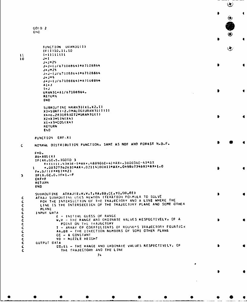
*
GO) 0 2ErgoCU
FUNCTION URAN3L(IlIF 1 10,11, 10
Ii I-IiLI tiI10 Jol
JnJ¢25
JJ-1-J/67108864)06710886 4
J*J*25j=J-|J/b67O8864)*67108864JLJ¢5J.J-(J/b7108864)*671U8864ALsJAIJ
URAN31-AI/67108864.RETURNEND
SUBROUTINE NRAN31(XIX2,I)X3*SQRT(-2.O*ALOGIURAN3I( 1I))X406.2831853072*URAN31(l 1X2aX3*SINIX4)xIzX3*COsIX4)RETURNEND
FUNCTION ERF,XI
C NORMAL DISTRIBUTION FUNCTION- SAME AS NDF AND FORAST N.D.F. I O
hU0.AX-ABSIXlIF(AX.GE.5.IGOTD 3
I +.0032776263)*AX+.0211410061)*AX,.O498673469)*AX+1.- oFu.5/I £F*•*3*~21
3 IF(X.GE.0.3F-1.-FERFsFRETURNEND
SUBROUTINE ATRAJIEWeVToAABBCC*YOODDEE)C ATRAJ SUBPOUTINE USES NEWTON ITER--ATION FOCKMULA TO SOLVE
C FOR THE INTERSECTION OF THE TRAJECTORY AND A LINE WHERE THE
C LINE IS ThE INTERSECTICN OF THE TRAJECTORY PLANE AND SOME OTHER
C PLANEC INPUT UAIAC E - INITIAL GUESS OF RANGEC WV - THE RANGE AND ORDINATE VALUES RESPECTIVELY, OF A pC POINT ON THE TRAJECTORYC T - ARRAY OF COEFFICIENTS OF ROUND'S TRAJECTORY FQUAriC.
C AABB - THE DIRECTION NUMBERS OF SOME OTHER PLANEC CC - A CONSTANTC YO - MUZZLE HEIGHTC OUTPUT DATAC CMtEE - THE RANGE AND ORDINATE VALUES RESPECTIVELY, CF
C THE TRAJECTORY AND THE LINE74
0 0 0 9 S 0 9 0 6
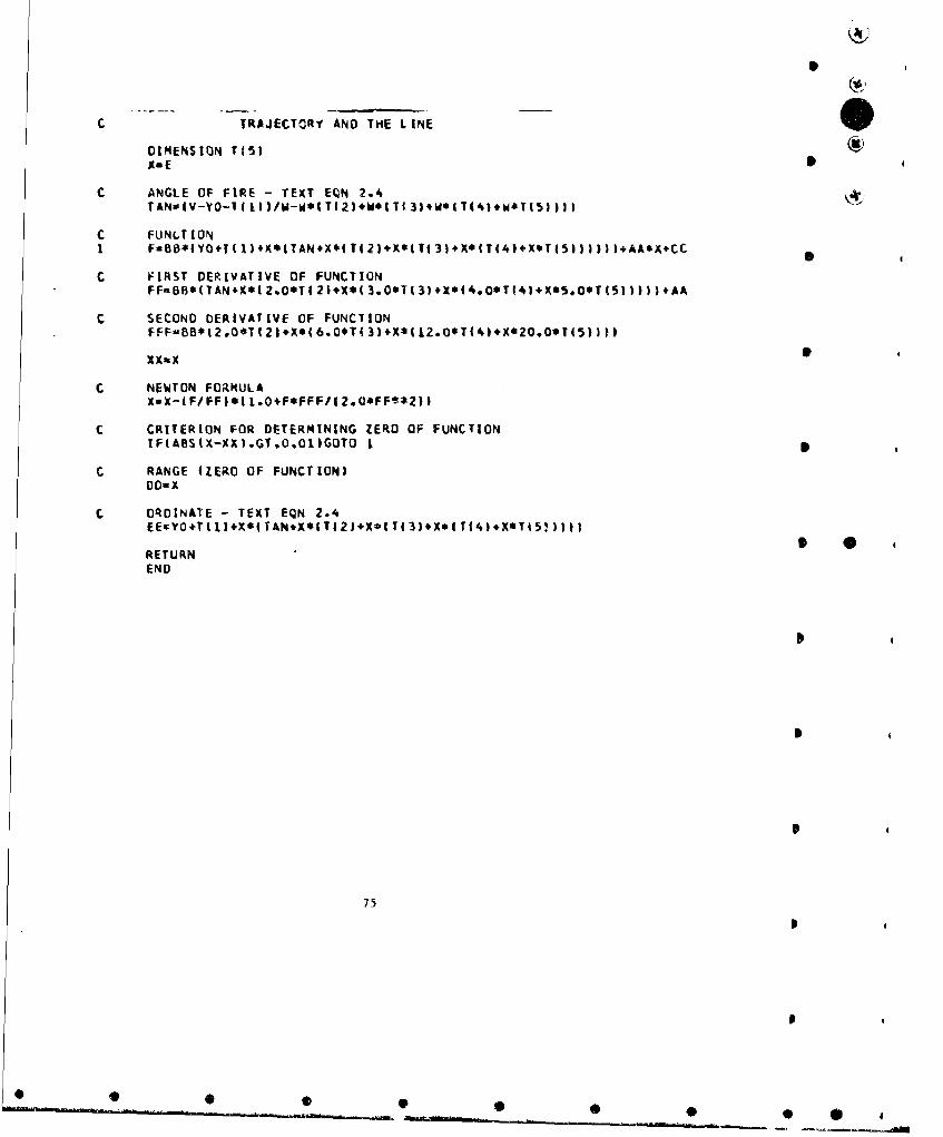
CTRAJECTORY AND THE LINE
DIMENSION T(1 actXa E
C ANGLE OF FIRE - TEXT EQN 2.4TANsIV-VO=1(II)/W-W*IT(2)W*WaTI3)4w*TY(4.W*T5153)f
C FUNLTIONI FaOB*IYO.T(l)4X*(TAN.X*(T(21.x9(T313+X*IT(4)+X*T(5I)))fl*AA*X4+CC
C FIRST DERIVATIVE OF FUNCTIONFFS&BBS(TANK*XI Z.O*TI 2).X*I 3.O*TI3).*XI4.00T!41.X*S.O*TI5)I) ))AA
c SECOND DERIVAtIVE OF FUNCTION
FFF-BB*(2.0*T121+XO(6.0*T(3'I#X*(12.0*T(41*X*20.0*T(5)))I
XXatX 0
C NEWTON FORMULAXsX-IF/FFI*( l.O4F*FFF/(2.UOFFt*2))
C CRITERION FOR DETERMINING ZERO OF FUNCTIONIF(A6S(X-XX)*GT*O,ollGOTO 1 0
C RANGE 4ZERO OF FUNCTION)DO- X
C ORDINATE - TEXT EQN 2.4EE,.YO+T(IU+X.ITAp*X*(T(2).*XIT(3I+X.ITt4),XeTI5'.),n
RETURNEND
75

I
5.3 Bunker Model
1. Basic Description
The bunker model is a Monte Carlo simulation of a weapon system engaging
the aperture oi a bunker. The modal provides for the bunker to be positioned
any place with respect to the center of a rectangular region and for the
region to be tilted to simulate the position of the bunker on various terrainI
slopes (i.e., level, rolling, hilly, mountainous) and/or rotated to simulate
various positions of the bunker relative to the firer. The ssumed technique
of fire for any weapon system considered in the simulation in to range-in
initially and then to sweep across a designated area MS times. I
The measures of effectiveness for the bunker model are P(l+), the prob-
ability of at least one hit within the aperture of a bunker after MS sweeps
and E(H) , the expected number of hits within the aperture of a bunker after
MS sweeps. A9 computed by the model, P(1+) and E(H) include both the
effectiveness doe to the rounds fired during the ranging-in process and the
effectiveness due to the rounds fired during the sweep phase of tho target
engagement. I
2. Assumptions in Modeling
The mathimatical modal assumed in the bunker model is a modified version
of the squad model. Therefore, all assumptions made in the squad model are
made in the bunker model with the following exceptions:
a. There is only one target (i.e., the bunker) aad it corr.cponds t
one of the individual men in the squad model.
76
0 f
* a
0 0 0 0* .

UI
b. The location of the center base of the tArget with respe.t to the
cente• of the rectan8gular region is an input into the program. There is no
requirement, however, for the center base of the target or tor any part of
the targut to be within the rctCangular region. The reason for this is
because in this model the region only serves as a criterion tcr ranging-in
(i.e., when the center of impact of the projectiles has landed within the
region) and as a basis for the u,6,-y coordinate system. Figure 1 presents
a typical target configuration for the bunker model.
3. Basic Formulas
The geometry used in the simulation, the equations required for the
simulation and the formulas used to evaluate the effectiveneus values, P(Ie)
and E(H) for Ih' LunKar model are exactly the s-me '9 for the squad model,
Ir ýt1' bi [teoto That P(I) and P(I-) when P([/HI), the pirbability t
1,,,¢ ..,, t ri )n given a random hi:t, it, .vr equi / one. rhtclelze va)- a
oC 10*+), urobabllity of at least one hit witlitn the aperture of a bunker
"as .... a :r Un iA number of rounds per aimpolnt and number of sweeps per
targeL engagment, are obtained from fmj in tne squad model by setting
P0(/H) equal to one in P(L)njn.
4. Notation and Units of Input and Output
Tabls 1 presents the parameters tequired as input into the bunker pro-
gram and the proper format statements for each parameter. Thu tollowing
notatlcu !s qced in preventing the format atateaunts:
Aw - alphanumeric field
£w.d - real number with exponont
77

I*
U)I
C
C,ci.0
C
4JC
- I
-� I*1 -
I.
4'
I-.o - I)
a0
-40 4'
I..
* I_______ .4
U
I ii
I *
'-4
I
I
4 7,..
a
S
* I S S 9 0 0 5

I
Table 1 Input Parameters I:or Bunker Program(2 c. rds/caio cnd 1 i.raJectory cart')
Svmbol Paramcrter Lill _I.ts Columns Format
2rq~ctryCard
T() - 1-15 E15.3
T(2) Coefficients of roundr -' 1-6-30 E15.3
To3) trajvctury equation . 31-45 E15.3
T(4) -, 46-60 E15.3
TO5) . 61-75 E15.3
w Round Sdentifi.cat1.zn 76-80 AS
Card 1
NREP Number of replications/target 1-5 IS'nrgagemenr,
MZ Maximum number cf rounds allowed - 6-9 14to range-in
NRA Number of rounds/aiampoint (<20) - 10-13 14
ANP Number of projectiles/rouLd - 14-20 F7.2
PRE t .p nen: of standard d.viatlon of 21-27 F7,2range estinmation error, a (o -1 PREx range)
N, Height, of muxzle of gun above me t rs 28-34 F7.2g ound
RW Dept:h cif rectangular region meters 35-41 F7.2
RL Length of rectangular x'miqion meters 42-48 F7.2
TH Angle theta (3) radians 49-55 F7. 2
PH Anglo phi (,) radians 56-62 F7.2
WM Width of buaker meters 63-68 Fb.2
HM Heighr. of bunker meuers 69-74 F6,2
AT(1) a Coordinate of center bane of maters 75-80 F6,2bunker (,relative to center ofrectangular regiour)
79
0S
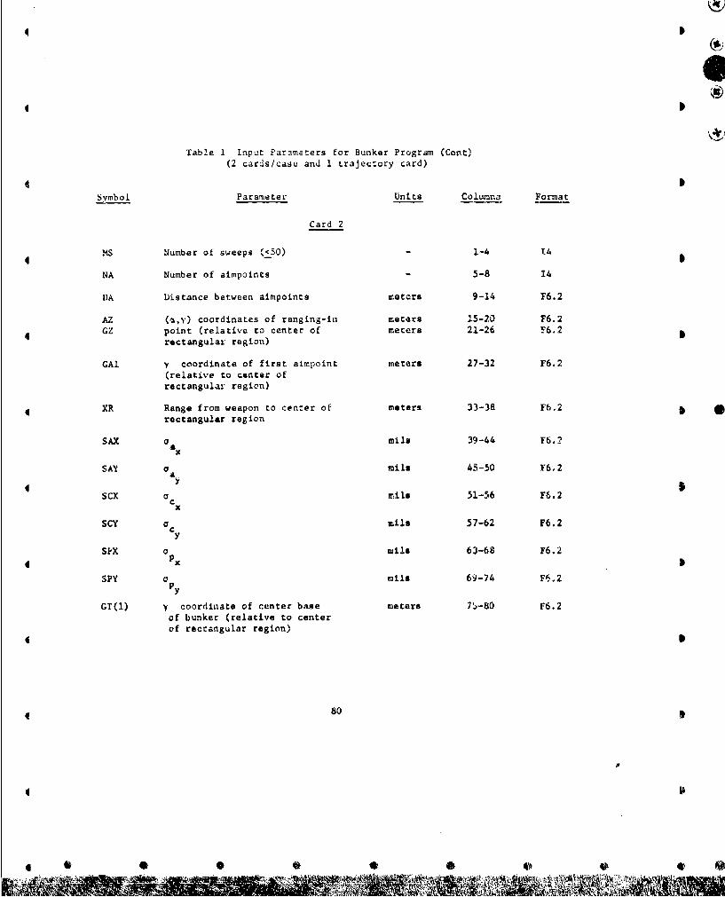
Table 1 Input Parameters for Bunker Program (Cont)(2 cards/case and I trajectory card)
*D
Symbol Par amnte Units Colttmnr Format
Card 2
MS Number of sweeps (<50) - 1-4 T4
NA Number of aimpoints - 5-8 14
DA Distance between aimpoincs meters 9-14 F6.2
AZ (a,y) coordinates of ranging-in meters 15-20 F6.2
GZ point (relative to center of meters 21-26 F6.2 0rectangular region)
GAl y coordinate of first aimpoint meters 27-32 F6.2(relative to center ofrectangular region)
XR Range from weapon to center of meters 33-38 F6.2 *rectangular region
SAX a mile 39-44 F6.2
SAY a mile 43-50 Y6.2ay
SCX a mils 51-56 F6.2
Cx
SCY o mile 57-62 F6.2
SPX a mile 63-68 F6.2
SPY C mile 69-74 F5.2Py
GT(1) y coordinate of center base meters 7j-80 F6.2of bunker (relative to centerof rectangular region)
80
9S
* 0 0 0 0 0 0 0 E

6
Fw.d - real number without exponent
1w - integer numbojrwhere
Sw - field width
d - number of decimal places to the right of the decimal point.
The trajectory card, which gives the coefficients of the trajectory
aquation for the round under evaluation must be the first input card. All
6 cases use these coefficients and, hence only one round is evaluated per run
of the program. Each case requires two input cards. It should be noted
that the maximum values of NRA and MS given in Table 1 can be increased by
* increasing the appropriate dimension statements in the program.
Explanations of some of the parameters and procedures for obtaining
some of the paameters are given in the description of the squad model. It
should be noted, however, that in one sweep it is not necessary to have
the entire length of the rectangular region covered by burst fire. For
example, if the bunker is in the upper right hand corner of the region, it
may not be desirable to fire along the length of the region, Instead a
Sbetter choice of aimpoints may be along a line paraile. to the front edge
of the bun~cer with the y coordinate of th'! first aimpoint to the right of
the a axis (See Figure 1).
The output for the bunker program includes many of the input parameters,
and the average effectiveness values, P(l+) and E(H), as a function of
number of rounds per aimpoint and number of sweeps per target engagement.
Thege value@ include effetivnes d o h rainging~i± procac's. Also
* given are the average number of rounds (bursts in evaluating a mcchine gun)
required to range-in and P(I+) and E(P) for the ranging-in process.
81

9 I
5. Numerical Example
One sample case was run uising the bunker program. For thia example it
wis assumed that a vehicle mounted weapon system firing three rcund bursts
with 10 projectiles par round was engaging a bunker whose center base was
located at the center of the rectangular region. The bunker was assumed to
be at an angle with respect to the firer and cn a terrain with some slope.
Table 2 presents the input parameters for the sample case and Table 3 pre-
*ents these input parameters as they appeared on the input cards for the
program. Table 4 presents the sample output for tha sumerical example.
This simple case was run on Ballistic Fesearch Laboratory BRLESC Com-
puter. Total running time was 1.35 min. while the compiling time was .37
minutas. The memory required was ilK.
0 S
82
011

0S
Table 2 Input Parameters for Numerical Example of Funker Program
Paramet.er Assumed Values
Coefficients of round's - .11009788E-1 3trajectory equation . 83401764E-4
- . 35845794E-70.OEC
- .61213832E-14Round identification 4No. of replicatJons 50Max. no of ranging-,in rounds 5 SNo, of roundc/simpoint 3No. of projectiles/round 10Component of standard deviation of .25
range estimation errorMuzzle height 2.5mDepth of rectangular region lOmLength of rectangular region 50m 5Angle 6 .5 radAngle $ .5 radWidth of bunker 25mHeight of bunker 5ma coordinate of cent -! bas•e of bunker OmNo:' of sweeps 10No. of a-mpoints 3Distance Uetween aimpoints 8ma coordinate of ranging-in point OMvcoordinate of ranging-in point OMScoordinate of first aimpoint -8.5mRaago 300m
o 4tayo Z2¶
C0 2U
x
PA
y coordinate of cent-r base of bunker OM
834 S
S @ • • 9 • @p

Vv
OD
.U
*00C
CLC
P-.0.7 -
ý4 01
w. ?.'
go 0
qN
,F!,
-'r'0
I N,
'CC
0.0
04 0
%jJ4

b
Table 4 Sample Output for Numerical Example of Bunker ProgramI
WIDTH OF BUNKER - 25.OOM LENGTH OF BUNKER - S.00WIDTH OF REGION a 10.00M LENGTH OF REGION w 50.OOM
BUNKER ORIENTATION - O.50ORAO TERRAIN SLOPE - O.500RADMUZZLE HEIGHT a 2.500M
NUMBER OF REPLICATIONS - 50
HORIZ DELIVERY ERROR - 4.OOMILS VERT OELIVERY ERROR - 4..OOMILSHORIZPROJ CISPERSION - I0.OOMILS VERT PROJ DISPERSION - 10.OOMILS
RANGING-IN PHASE
NUMBER OF BURSTS REQUIRED a 1.32 E(H) a 5.28 P(1+1 - 0.988S
SWEEP PHASE
RANGE P1I/H) NO OF NO ROS/ NO PROJ/ NO OF E(H) P(1+) t 0IN) AIM PTS AIM PT ROUND SWEEPS
300. 1.000 3 1 10. 1 16.31 1.000300. 1.000 3 1 10. 2 27.65 1.000300. 1,000 3 1 10. 3 38.64 1.000300. 1.000 3 1 10. I 48.94 1.000300. 1.Oc 3 10. 5 59.95 1.000300. 1.000 3 1 10. 6 71.11 1.000300. 1.000 3 1 10. 7 82.44 1.000300. 1.000 3 1 10. 8 93.63 1.000300. 1.000 3 1 10. 9 104.75 1.000300. 1.000 3 1 10. 10 115.56 1.000300. 1.000 3 2 10. 1 27.16 1.000 p300. 1.000 1 2 t0. 2 49.82 1.000300, 1.000 3 2 10. 3 71.87 1.000300. 1.000 3 2 10. 4 92.72 1.000300. 1.000 3 2 10. 5 114.90 1.000300. 1.000 3 2 10. 6 137.09 1.000300, 1.000 3 2 10. 7 159.86 1.000300. 1.000 3 2 10. a 182,13 1.000 0300. 1.000 2 & 10. 9 204.15 1.000300. 1.000 3 2 10. to 225.83 1.000
85 I
fit

I
Table 4 Sample Output for Numerical Example of Bunker Program (Cont) (g)
300. 1.000 3 3 10. 1 38.28 1.000300. 1.000 3 3 IQ. 2 72.20 1.000300. 1.000 3 3 10. 3 105.33 1.000300. 1.000 3 3 10. 4 136.71 1.000300o 1.000 3 3 10. 5 110.16 1.000300. 1.000 3 3 10. 6 203.60 1.000 0300, 1.000 3 3 10. 7 237,57 I.OGO300. 1.000 3 3 10. a 270.74 IOGO300. 1.000 3 3 10. 9 303.91 1.000300. 1.000 3 3 10. 10 336.41 1O000
8
* 0
86
S
• • • •@ • •
SJdB CH6 L KOCELS- ,KP-29. TCM-Em3f06
C
C THE BUNKER MODEL IS A MONTE CARLO SIMULATION OF A WPN SYSTEM EN-C. GAGING THE APERTURE OF A BUNKER. MEASURES OF EFFECTIVENESS AREC P110', THE PROBABILITY OF AT LEAST ONE HIT WITHIN THE APERTUkkC AFTER MS SWEEPS* AND El HI, THE ExPECTED NO OF HITS (PER APERTUREC ENGAGEMENT) AFTER MS SWEEPS.C ASSUMPTIONSC MODIFIED VERSION OF THE SQUAD PROGKAMC USES CLOSED-FORM TRAJECTORY APPROXIMATIONS
DIMENSION AT(1OO),GT(IO0)bTI5),EH(2C),P(20, 100),TEH(20,50)DIMENSION TFBAk(20,50)
L INPUT DATAREAC(5vI) (T(I1),1= 1.,slW
I FORMAT15LI5.3,A5)2 REAP'593)NREPML,NRA, ANPPREYORWRLTH.PH,WM,HM,AT( 1)3 FORMATI I5,21497F7.Z23F6.2)
RL.ADU5,4)MS,NADA,AZGZ,GAI,XR,SAX,SAY,SCX,SCY,SPX,SPYGT(l)4 FORMAT(214.12F6.Z)
C P(L.)=P(I) WHEN P11/HI, THE PROB3ABILITrY OF INCAPACITATION GIVEN AC RANDOM HIT, IS SET EQUAL TO ONE (NOTE - P(1) a P(I/H)*P(H)i
PHK=1.0
C, ONE TARGET - THE BUNKER (NOTE - THE BUNKER CORRESPONDS TO ONE CFC THE INDIVIOUAL MEN IN THE SQUAD PROGRAM)
NT-I
1-0S * 6ERI&O.0EHZO0.0FBARZO.0RN- NPEPTN-NTDO 5 MsI.MS00 5 J-jnl.A LTEHIJ,RjO.o
5 TF8AR(JM)w0.OSTHmSIN( TN)ClHaCOS( TH)SP14-SINI PH)CPHuCOS( PHIYR&0.SSRW*$PHDO 28 NR-1,NREP
AA-AZGA-ClZLL-ri SVImYR+AZOSIPHXZ-XRtAZ*CTH*CPH.GZ*STHYZ-YR+AZ*SPHZZ=-AZ*STH*CPN*GZOCTHCALL NRAN31(TNl,TN2,I)QA-PRE*SQRT (XZ**2.(YZ-YO)0*2.ZZ*.2 )*TNI00 8 1-I.#T 87 6
fpS

00 7 JL,.NRAEH(I-0..0
7 P(JN)M1.0a CONTINUE 4
NOSIDc 28 M-I,PIS
9 CO 23 L&IvLLXI' KR AS*CY CP H GA S THY I-YR+AA*SPH1 1.-AA*STH*CPNGA*CTHCHI-ATAN(ZI/Xi IISCISINICHIICCIuCOSICHiITA=ATANI (YI-YOI/SQRT(Xl*S2.ZI**21ýSTAwS INI TA)CTAnCOS(TA)CVMuSQRTIXIee2sIyI-Y0Ie*2ZlI**21/I101859IF(IZ.E0.1ICVM-CVM4-OA/IOL8.59SXKA- SAX *CVMSY A S AY*VMSXCU- l*CVMSYC-a.,y~CVMlF(1Z.EQ.3)COT0 10UI-(XI.QA*CCI*CTA)*CCI.IZI.QASSCI*CTA)*SCI4X'-UI*CC'
Z K-U ISCITA-mATANtI(YI-YO)/SORT(XI**2411ee2)ISI AmSINC TA)CTA-COSI TAlQA-0.0 * a
10 CALL NRAN31IRNItRN2,II00 19 MMaINBCALL NRAN311SNlvSN2,1)RAu'SYACRN14SYC*SN 1S A-SXKA*R N2+*SX C*SN2XAiKI.QA*CCI*CTA--RA*CCI*STA-SA*SCIYA.Y!eQOt~TA*2A*C'TAZA-Z I.QA*SCI"CTA-RA*SCI*STA*SA*CCICHA-AtANI ZA/XA)SCAwS INICHAlCCAmCOS CCHA)U)AoxAsCCA+ZA*SCAVA-VAAa--ICPbiS*2.CTIISSPH.SCA.STHSSPH.CCA I'*2)8aCPH*C -CT H*SPH*CCA+STH*SPH*SCA IC- C-CTHSSPHSCC;A.STHOSPH*SCA )*ICTH*SPN4SCA+STM*SPH*CCAIIF(IZ.EQ.3)GOTO 13AL a-C T H* SP *C C A *5TH* SP H SC AAM- CPHANsC.T,4SPH*SCASrHCSPHCCADGo-I AL*XR*CCA+AD4*VR-ANOXROSCA)GO TO 12
II 1-2AI-O.0AM- 1.0
12 CALL ATRAJIUAUAVA,1.oALAMDG,ý'O.U8,VBIIF(VB.LT.0.-O01)GOTO 11 6
13 00 19 NwI*NTIJCo.0. 88
wcM0.0 db
CL-0.0S~oO.0 5
00 16 J11.#2UT I XR+AT (N l*CTH*CPI4-BTSCTH*SPN.GT IN)*STH3*CCA.li-AT IN) *STH*CPv4.BT*ST#ISSPH.GTIN)*CTHI*SCAVTOYR#ArENI*SPH*BTOCPHwTs.(XRATINIOCVH*CP4- BT*CTH*5SPH4!.T(N3*STH)*SCA+li-A!EN)*STH*CPHBT*STH*SPH*GT(NI.CTH).CCA 4
GOTOE 14915k ,JJ14 DTrn-(A*UT4B~lVT4C*hdT)
CALLATRAJI Ul.UArVA. T :A,8,CTYO. UPVPICVM-SOQ1T(UP**2.(VP-YO34*2 )/1018.59SXPUSPX'CVMsypuspy~cvmOMAX.4.O.SPX*SQRT(UT.'2.I VT-YOJ**2 3/1018.59IF(ABS(WT)-WM/2.O.GT.DMAX)GOTO 17oS.-lUP**2#VP*lVP-YO3)
15 CALL ATRAJ(UTUT,VTT,UP,VP-YO,OS,YO,U,VI
WCmWC#.S*WT4CLm-CL+UCM- -CM.VCNd--CN+Wy
16 BT'lHNHPM-SQRT ICL**24CO*e2*CNO*21YBARm(CL*(UP-UC).CM*(VP-VC'3-CN*wCI/HPMXBARUSQRTI EUC-UPISS2.IVC-VP3S92.WCS*2-YBARS*23tIFWC.GT.0.0)XBARs-XBARHa(ERF14.5*WN-XBARI/SXP3-ERFf(-.5*WM-X0AR)/SXPI)*1(ERF((.5eHPM-YBAR3/SYPJ-ERFII-.5*HPM-YBARI/SYPJiSP-( 1.0-PHK*Hl**ANPGO TO 18
17 sp- L.0HS0.0
1800 iljq 44,~EII(J)AEH(J )*AmP3HKF(P(J,N).LE.1.0E-20) GO TO 19PIJvN)%PIJ,N3*SP
19 CONTINUEC 19 PlJtN3-P(JtN3*SP
GOT042O.21#22 3,1'20 AB-IUa*CrH.CCA-UB*STH*SCA-XR.CTHI*CPH.SPI1*(VB-YR)
GB=UB*STH*CCA+UB*CTH*SCA-XR*STHIF(-$RW/2.0.,LE.AB.AN0.AB.LE.Rbj/2.O.AND.-ftL/2.O.LE.GB
1.ANO.G8.LE.RL/2*O)COTO 2421 XB*UB*CCA
Z 6-usi S CA 4
CALL NRAN31ITNL.TNZgI)QA*PRE*SORT I(XZ-XB )'*2,(YZ-YI3)**2.( ZZ-ZB)**23*TNI
GO TO 2322 GAaGA*DA23 CONTINUE
IFIIZ.EQ*3)GOTO 286LuL-1 89

Sd
24. IZ-3LL-NACALL ATRAJIUI ,UIVITAL,AMDG.YcUtLIlVlIAAaIUl*CTH*CCA-UL*STH*SCA-XR*Clj,.*CPH4$PH.IVZ-YRIGAvlGAI.PRE*TNAABS(GAI IERl-ERL.FLOAT(L I/RN.QAw0.O00 25 NalNT
2S SPL-SPZ4P(19NI/TNEHZ-EHZ*Ei~IlI/RNFBARlaF5ARZ.I I.O-SPUl/RNNO-NRAGO TO 9
26 CALL NRAN3l(TN1,TN2#1)GA-sGA1,PREvPTN2*ABSIGA I)D0 28 Jo1,NRAsPsMo.0DO 27 N*19NT
27 SPS-SPS+P(JN)/TNTEH(J,MI*'TEH(J#M)+EH(J I/RN
26 TFBAR(J,M)aTFBARtJMI+( 1.O-SPS)/RN
C OUTPUT DATAWRITE(6t293W
29 FORMATI1I1 #37XtA5)WRITE(6,301
30 FORMATILHODWRITE(6@321WM*HP4
32 FORMAT11H ,12X,17HWIDTHi OF BUINKER N,F7.2,lH41,5X,IL8HLENGTH OF BUNKER n,F7.2#lHI4)WRITE(6933)RW*RL
33 FORMAT(IH ,12Xvl7HWIDTH OF REGION otF7.ZttHM*5xt1LBHLENGTH OF REGION uF7.2,1Hp43WP. ITE( 6,34)TN, PH
34 FORMAT(IH ,7X,20HBUN.KER ORIENTATION mtF7.3t3H1RAO,5xo115HrERRAIN SLOPE avF7*393HRAtiWR ITE 6, 5)
3S FORMATIlH .28X,1.5HFKUZZLE !4EIGHT -,F7.3,IHM)WdRITE(6, 38)NREP
36 FORMAT1iN @25Xw24ti4UMOBER Of REPLICATIONS n#151WRITEt 6.37)
37 FORMAT(Ili )WRITE(6. 38)SAXeSAY
38 FORPIAT(IH ,SKv22MHURIl DELIVERY ERROR a#Fb.Z,4HMILStISX921HIVERT DELIVERY ERROR -,F6.2t4NMILS)WRZI Ef6t391SPXvSPY
39 FORMAT4LH ,4X,23HHORIZ PROJ DISPERSION M.Fb.Zo,4IMILS,15X,22HVERT PROJ DISPERSION wtF6.294HMILS)WRITE(6*30)WRITE(6,30)tIRITEI6t40)
40 FORMATIH ,31X,16HRANI4GNG-IN PHASE)biRITE(6v30) rWRITE(6,41 )ERZ,EHZ ,FBARZ
41 FORMATII t5X927HNUMBER OF BURSTS REQURED -OF6.2,16X96HEIH) uoF6.Z,6X#7M.PlI+) ,tF6.31WRITE(6,30)WR IT E(16,30)WRITF(6&42)
4,Z FORMAMHI #34X1ItHSWEEP PHASE)WRITE(6,001 90

WA ITE( 6, 43)43 FORMAT(IL v4X#72HRANGE PUI/HI NO OF NO RDS/ NO PROJ/ N
10 OF EHIH) P1)URITE(6,441
44 FORMATIIH ,5X.53H1W1 AIM PTS AIM PT ROUND Sw1EEPS)WRITEC6, 30)CO 46 JwINRA00 46 M-IvMShiRlTE(6945iXR.PHKNAtjANP,M,TEH(J,M) ,TFBARIJ,MI
4-5 FORMAT(I H ,3xF5.0,3X,F6.3t4X,14,7Xel396XsF5.0,6X,13,,4X,F7.2,3X,
46 CONTINUEWRITE(6947 I
47 FDPMATIIHII
GOTO 2EN 0
FUNCTION 1'RAN3l(f)IFI 1)10,11#10
11 lIMlLI1ill10 J-1
4 Jul'25JaJ-I J/6?108864 )*6710986-kJ-.1625JmJ-IJ/67108864)0671I08864
J*J-I J/6?1088641*67106064AluJ
URAN3 l.A j67 1080 64.RETURN
SUBROUTINE NKAN3I(XI,X2*I)XJm3WP~i I .04ALiiUUIUIA'VN3 1P&1
X4a6 .2831853072*URAN311 IIX2-X3$6 'NIX41X1-X3*COS(IX4)RETURNEND
FUNCTION ERFIX)4C. NORMAL DISTRIBUTION FUNCTION, SAME AS NOF AND FORAST N.O.F. b
FwO.AXIIIIABSIX IIFIAX.C.E.S.IGOTO 3
F.l(1(I.'i83E-5*AX,.488'9O6E--4IAX+.38003b5E-4I*AX
4 3 ItFIX.CE.0.;F-l.-FER F*FPET URNEND
91
Eli,

SUBROUT INE ATRAJ(EP1W,V,T,AA,BBICCYYOgaDEE Ia DIMENSION T(5)
X. E
L F*BB*(YO+T( ),x*XITANU*XIT(2),X*(1(31.X*(1(4),X*T(5fl3 II).AA*XiCC
FF.BR*ITAN*X*(2,O*T(2I)*X(*3.O*rI3I+X*14.0*T(4)tX*5.O*TI4I)II,)AA
X-X-(F/FFi*(I.OF*FFF/(2.O9FF**2I)IF(A3S(K-XX?.Gi-.O.01)GOTO I
FE.YO+y(1I+X*ITAN+X*(TI2)4X*(T(3I*X*CT(4IX*T(5a))))RETURNEND
40 0
6WON
S
S
5.4 Hemisphere Model
1. General Description
The purpose of this paper is to study the effectiveness of machine
gun fire on a point target of hemispherical configuration. This paper is
intended to provide an essential background of the subject area and an
example so that the reader can apply the model with a minimal investment
of his time. S
The approach of this study is to use Monte Carlo :imulation routines
to vary certain initial conditions of the projectiles and observe the
projectiles in relation to the 3-dimensional target region. The measures
of effectiveness of the projectiles in relation to the target area are
P(F),P(S) and E(H). This study uses the flight equations as discussed in
a previous Y.rort of this command [8].
The following basic definitions have been rendered for the sake of
clarity:
P(F) - the probability that the first round of a burst
intersects with -he target region
P(S) - the probability that the subsequent rounds of a
burst intersect with the target region
E(H) - the expecoed number of rounds in a burst whichshould intersect with the target region
The remaining portion of this paper will cover basic assumptions of
the modeling, the basic flight equations, a discussion of the computez
usage, a numerical example based on pseudo-dcta with sample output, and
general comments on the scope of this study.
93
p
4 S 6 0 0•

I
I
There act two (2) basic assumptions that are used throughout the suc-
LeSSIVe development. The first aýsumption is that the fitst round in a
burst may be significantly displaced from the center of impact of the sub-
seq.erit rounds of a burst.
The second assunption made is that the rounds per burst were randomized
such that five, trivariare normal distributions - mutually independent with
respect to three axes - would characterize the initial dispersion of rounds
about the muzzle. Three normals characterize the initial displacement and
two normals characterize the initial nwuzzle velocities about the muzzle.
Based on the above assumptions and the kinematics oi the projectile,
the efrectiveness of the weapon system i, studied.
3. Basic Formulas
The notation of the following forno;Tation is based on a Euclidian
3-space coordinate system where the ovigin of Xi for i-1,2,3 is located
at the weapon; The positive X -a)is ',9 the lateral coordinate to the
right; the positive X,-axis is the rztngewise coordinate, and the positive
X -axis is the vertical, upward cr-;r•inate (See Figure 1).
.-- A Projectile Path
Target
Figure 1 Coordinate System and Target
94

The first round about the muzzle may be dunoted as a vector ,
whose endpoint from the origin would be (X,,oX IX 0) (See Figure 2).
Similarly, if the vector of a subsequent round about the muzzle is denoted
as X2 0 ' then one of its endpoints would be (X120 X2 2 0 , X20). Finally,
if th2 vector difference (called cffset) bet.eerz the first round of a
x 3
(X ,X ,X,)110, 210' 310.4
xIC (x ,x )12Q 720: 3.20
S 2O2
/- K-
x 20/ " •
x
Figure 2 Coordinate System with Initial Vectors S
burst and the center of impact ýxx of subsequent rounds of the samed.0
burst were denoted as X3 0 1 then in general the offset of burst could be
equated as
K3 0 s Wx20- 10 (3.1)
The means and variances of the normal, trivariaLe ditLribuLiotiý Of LIIe
first round, subsequent rounds, center of impact and offset in all three
95
Si I
*O
dimengicns are denoted Is follows: p * o2x ; px , a2 ; and
x ± 1o i 2' 20a a2 for i-l,2,3.
In a similar manner the initial velocities use the same notazion.
The first round would have a velocity vector V10 where one of the end-
points would be (V 210,V310), and tle velocity vector V10 of a
subsequent round would have its endpoint of (V1 2 0 ,V 2 2 01 V3 2 0 ). Since the
velocities are normally distributed, the means and variances of the first
rounds and subsequent rounds are the following: Ui ' V ±210' and VJ20,
a2 for i-1,2,3.Vi20
The basic flight equations are based on the following six (6) equ-
ations (8):
V1 - V1 0 e~TV, - Voet
V2 . V20e - t
. t + (1-eyt)V3 * V3 0 eX + L( V)(.2V 0 VIY -Y (3.2)
X , --- (e -1 ( )
K2 -K 2 0 -- (a -1)
X - x -3 (e _t 1 ) + R (t +3 30 V V
where Vi for 1-1,2,3 is projectile velocity at any time t
X for -.1 , is piolectile position at any time t
V aiad X i for ±-1,2,3 is initial velocity and space component
g is the gravitational acceleration constant
and ± is velartd to the projectile drag.
96
Assume that a projectile of mass n' and caliber d Is passing A.through a medium of cunscant density p where the velocity of sound a
is constant. Then a drag coefticient K. exists such that
a 0KD w 6a%/V M - T-V 1 (3.3)
where M is Mach number and 6 is the constant of proportionality. Taking S
one more step,
y- -Ba •d2/m 93.4)
is the quanzity that is used in the above equations of motion.
The program analyzes a weapon's effectiveness in the following manner.
The effectiveness measures of r(F) and P(S) are based solely on rstio of
number of hits per number of firings. The expected number of hits, E(H) S
is computed as
E(H) - P(F) + (N-I)P(S)
where N-number of rounds per burst. In addition, the mean value and
stantdard doviacion of the hits are measured per coordinate for the first
rounds and subsequent rounds per burst.S
4. Computer Program Usage
The prograr. is written in FORTRAN IV language for the IBM 360/65 machine
with a mainprnoram ,rtw (2) SIIRROUTINES and one (i) FUNCTION routine. The
program solves cerLain formulas for target effectiveness based on the
desired number of replications (bursts) per case.
97
0 00 0I 0• O 0

I
I
Originally the program was written vith single precision accur•cy.
However, due to the large magnitcude of range and the small variations of -'
impact coorJinatcs. single precision was meaningless &nd hence double pre-
cision accuracy was used (IBM FORTRAN card: LMPLICIT REASL*8(A-H,0-Z))
Duo to the problem of large renges, small variances of impact co-
ordinates, and large sample sizes (i.e., large number of simulated round.),
it is possible for the machine to compute a negative variance in the range-
wise impact coordinate (which of course cannot be correct). To guard
againsL such an occurrence in computing variances of ouccessive rounds only,
impact points were stored in vector arrays for the respective coordinates.
Then the Lasic formula for variance was used.
One type of output the program renders is mil dispersion on the target
in all three coordinates where each linear fo£0 is multiplied by 12,000 to
render mile (i.e. , "mil-inches"). Since al) the inputs of this program are
not accurate to the magnitude of the mr.li-inch nor is the projectile's
dimensions even considered in this program, the mil dispersion yields very
little useful information. On the other hand, the variances in feet can
render valid and useful information.
Table I yields a listing of the input variables. an explanation ot
some of the variables is rendered below:
NCASE. When NCASE-O, then the program temtinates; otherwise the
variable may assume any arbitrary value.
DT. Tho initial tiiCe increment for which the projectile squa-
.ion' anre solved for each rhnnce in rime
98

AMA.
00 0000000 000000)
2225 dddoo ooooou
'IV0.n'm 00 00a0 0 0
Do r-)f -CN~- l1- - NlL '
m IA
- CT T M 0 -aC, -J a
-3 W( ~ 1CU ' CU 1-C 'a~~- U
0 C
'-99
o0 0 0 0ia C3 0C Q0
C~ ~~~~ 0 0 0 0 0 0
4 p4
C00000 C 00 0000 03 0en
;- >N >f >t >44 4 r
U . .1 -O -n V) -i -r4 c p ,-I
(N fl 4 V%.4C'Jl4V2.4 (
b V0uuLu
0 0o U C~ 0 0 0 0 0 0 0 0
04 a~ N u l 4 1~lNl -go
ICC
U N N ~14 0 0
0 w W - :' e
- 44' N CV
.4 00 4 a
C: :Ie
_lc iL l. f .p
abc 0 0 0 0 0 0 uU r s ni
00000 Cm 0 00 C)
I. z 0
Q D4 4 P4 K 4 w4 - 4 4 -
'-P4
Ct'
W4)W4WU
04.4 . P-44 4 .
OOOCO~ 00 0 0
10

S]
IIMI. A Lire- estimate wncrebv most of the projectiles will not .
nave hit the target. If the urojoctile has passed the target for that
tmial than the proguam w!ll select a proper starting time for that pro-
jectile.
(XIA,X21,x3A). This point is a sulected aim point on the target
surface 6hich serves no useful putpoze. One act of output describes the
two angl-s 6i (deflection In radians) and 80 (elevation in radiatns) of
the line of sight with the aiming point.
The logic flow is briefly as follows. The first projectile is simu-
laWed by sampling from two (2) trivariate normnl distribuzions: one for
initial (firsc-round) displacement, and another for initial (first-round)
muzzle velocity. Then the subsequent rounds are fired for the remainder
of the burst by sampling throw (3) trivariate normals: one for offset,
another for initial (subsequent-round) displacement, and the third for
initial (subsequent-round) velocity. The above is iterated for NREPS times.
The 6imulated projectiles aze observed to determine if they hit the hemi-,
ahr a, if1so, at *4.., ti-.4
The progrAm output consists of printing P(F),P(S),E(U:, and the means
and variances of the hits in each coordinate in bnth eeat ani mila,
II102
9b * 0

S
5. Numerical Example
As an Illustration, let us consider a machine gun firing on a hemi-
spherical target downrange with the following weapon system data:
SXI0 - 1.5 x 10-5 SX120 - 1.5 x 10-5 SX130 - 7.0 x 10- 5
SX210 - 3.0 x l0-5 SX220 - 6.0 x 10-5 SX230 - 8.5 x 10⁻⁵
5X310 - 1.0 x 10-5 SX320 - 5.0 x 10-5 SX330 - 1.12 x 10⁻⁴
UXi10 - 3.0 x 10⁻⁵ SVI20 - 0.3 UXI30 - -5.Q x 10- 5
UX210 - -6.0 x 10⁻⁵ SV220 - 50.25 UX230 - -1.1 x 10-4
UX310 - 2.0 x 10⁻⁵ SV320 - 0.4 UX330 - 1.0 x 10⁻⁵
SVllO - 0.1 AV120 - 2.0
5V210 - 50.0 AV220 - 3500
SV310 - 0.2 AV320 - 3.0
AV110 - 2.0
AV210 - 3500
AV310 - 3.0
Further, the center of the 6 feet hemisphere is locatel at
Al - 1.36664 A2 - 2392.07 A3 - -9.5
with the firer aiming at a point
XlA - 1.0 X2A - 2400 X3A - 1.0
and the projectile will travel for a minimiu time (TMIN) of 0.890 seconds
before checking fUx a hit in ±ta-••1 ti±% tn.re..e.. • (I)T) Of 0,001
seconds.
103
S• • • • • •

4
p
I
The follýwing envLcronental conditions exist:
G - 32.175 M - 3.774 x 10-
P - 2.377 A 10-3 B - .25
D - 1.9685 x 10⁻² AO - 1120.27
Lastly. the following controls were imposed:
N- 6
NREPS - 200
4
Under the above conditions, the following results were obtained.
P(F) - 0.8950
P(S) - 0.8090
E(H) - 4.940
Sinca somn projectiles hit the target region then the means and variances
of impact points in all three coordinates may be useful (Table 2): S
Table 2 Means and Standard Deviationsof Example Case
Xl X2 X3
MeanA - let round -0.00632 -5,96803 0.53.76.Std Dav - Ist round 0.07603 0.03331 0.30275Mean* -, Subseq rd -0.01404 -5.95672 0.58392
Std Dev - Subeeq rd 0.19624 0.040717 0.34,59
Mean is adjusted for center of hemisphere
104
aD
0 0 0
C SY -TNIO-70 5.4 HEMISPHERICAL TAKGET MODEL OCT.-10CC THa FOLLOWING IS MKJNTE CARLO ROUTINE FOR STUDYING MACHINE GUNAC EFFECTIVENESS ON A POINT TARGET OF HEMISPHERICAL CONFIGURATION.CC
IMPLICIT iREAL*13(A-H.3-ZIOWVENSIUN ill IOOT),U( Jl0O1)Z3( 1001)COMMON A1,A2,A3.RltGAMvGtTMINPDTC-OMMON/ SRANOM/ ISEED
1 FORMAT (Itili2 fORIMA(3I5o2F10.013 FORMAT (8F10.014FORMATI 1X,'MCASESN,NREPS.Rl,DOT',1t,3I5,2FI0.51S FORMATI iX,'AlA2,A3,XlAvX2AX3ArTM1NI/lXt0E15.6I6 FOIa4AT2IX,'G,PDXMBAO'11X,8EI5.6)7 FORMAU1IXOSX10,SX(2lOSX3lOUXIIOUX21OUX310 - SVIIO,SVZIO,SV3IOt ,AV1IO.AV2IO! AV3IO'/ lX, 6E15.6/IX,6El5.6)
8 FORMAT(1~sSXI2OSX220qSX32O - SV120,SV220,SV320,AV120,AV220,A'I32O
9 FORMATfI Xt'SX130OX230,SX330,UX13O.U2X23OUX330h1IX,8E15i.6)ISEEOm7791261D0 110 IC=10ý00CWR~ITE (6,11READ (5,2) NCASEP,NNREPS,R1,DTWRITE (6,1111 NCASEIF (NCASE.EQ.O) CALL EXITREADI5#3jAlA2,A3,XIA,X2A,X3A,TMINREADI 5p3)GvP,0,vXMv8.AOREAD 15,3) SX110,SX2IO. SX31OUXL1O.UX210,UX310REAO(5,3)SV110,SV2IO, SV310,AVI1OAV21OAV310READ 4503) SX1209SX220,SX320REAO4 5,3)SVl2OSV220,SV320,AV120,AV22O,AV32OREAD (5@3) SX130,SX230,SX330,UX130,UX230,UX330
NH2=0
N 12-0SYlwO.ODOSY2uO.ODOSY3=0 .0DOSSY 10. 000
* ~SSYZ-0.0DOSSY3s0.0D0
Si 1=0.000SZ3-nO.ODO
C DETERMINE AUILINE OF SIGHT DIST TO AIM PT),THLIDEFLECTION),a c AND TH2(ELEVATION) IN RADIANS WITH RESPECT TO ORIGIN.
AmODSfRT( Z1A4X1AX2A*.A2At)X3A*X3A)THI-DARCOSI XIA/AD)TH2=DARCCS(X3A/AD)
* 105
WRITE(694) NCASE#NvNREPSip1.o0T wWRITEI6,5)AlA2,A3.XlAXA.X3A.TMIr4 0
* ~WRITE 6.6 )G,P,DtXMoBvAOWRITE(6,7) SXIIOSXZIO.SX310,uxIEo,UXZ1O,UX310,SVI 10,SV21OtSV310,1AVkIOAVZ 10iAV3IOWRITE(6,8 5 SX12O.vSX2209SX320, SVIZOSV,220,SV32OAV12O.AV220,A.V320WRITEC 6,9) SX 130, SX230. SX330,UX130,LIX230*UX33GWR ITE (6. 113)3TM INGAM, ADTHI, TH2
C 00 100 LIuI.NREPS
C SIMULATE FIRST ROJNO OF A BURSTC
CAL.L NORMAL(El.E2)X~l10wSX1 10*EI.UXIIOVI 10-SV I IO*EZ+AV 110CALL NORMAL(ElE21X21Q=SX210*E1*UX210V2 10*SV210*E2*AV21OCALL NO1RMAL(ElIE2)X3l0aSX3IC#E 1*UX310V3IOmSV 3lO*EZ*AV310NTYPEuO
* ~CALL FLITEIXlI0,X21C3,X3lOV.110.V2l0.V310,THi TX1,X2,X3,,V!,V2.V3,INTYPEeNH19UH21lNIllN 11.1
C DETERMINJE 1ST ROUND MEAN AND VAR OF TARGET DISTRS IFTLMILS)IF(V2.EQ.0.0)G0 TO 10
Y2anX2-A24* Y3=X3-A3
WlwNNI
SYINSYZ.Y1SY2-SrZ.*Y2S13sSY3+Y3
* SSY2-SSY2*Y2*YZSSY3=SSY3*Y3*Y 3
CC SIMULATE SUBSEQUENT ROUNDS OF A BURSTC
10 4N=N--1DO 100 LZ-t*NN
* CALL NORMALlElE2)Xl30nSXl130'EI*UX130CALL NORMAL4EIE2)X230-SX230*( l*UX23OCALL NDRM !,L(Ek9E2)
UX120*XIIO*X130* UX22OsX2lV+X230
UX320-X310+X 330CALL NORMAL(EI,E2)XIZOuSX 120*EL+UXIZO
* 106
0F
V120xSV120*E2+AV12QCALL NORMAL(EloE2)X220aSX220*El1*UX220V220-SV22ObE2+AV22OCALL ItORMALtEI,E21X320nSX320*E1+UX 320V 20ouSV320*E2-+AV320NTYPE-1CALL FL ITE(XL2OX2Z0aX3ZO, Vl20 V22OV320,THITXlXZX3,V1 ,V2,V3,1 NT VP ,N11, NH?)N12mNI2+1
C DETERMINE SU8SEQ ROS MEAN AND VAR OF TARGET DISTRS (FTLMILSIIFIV2.EQ.fl.O)GO TO 20
C STORES DATA POINT$ ADJUSTED FOR CENTER OF THE HEMISPHEREJ*NH2U 2-N H2ZI(J 3-X 1-AlZ2(J),.X2-A2Z3(J )-X3-A3SZ ISZ I.Z I(J)
4 SZ~uSZ2+Z2(J)S13-SZ3+Z3tJ)
20 CONTINUE100 CONTINUE
Cc
).01 PF-OFLOlAT(NH1)/D'FLOAT(NIl)PSwDFLOAT(NH2)/DFL0AT(NI21E14-PFI (N-i 1)*PSWRITE £6,116t] Pr-,PS,EHNH1,NI1,NH2,NI2IF(EH.EQ.0.OI GO TO 110
C MEANS OF IMPACT POINTS IN 3 AXES - ST ROUNDIFINHI.EQ.01 GO TO 105YIBAR-SY 1/Wi
4Y2BAR=SY2/W1 tY3BARftSY3/Wl
C MEANS IN MILS - 1ST ROUNDYIBARM&YIBAR *1200C.ODOY2BARMsY2BAR *12000.0DODY38ARMmY38AR *12000.ODOIFINHI-1) 102, 102, 103
4 102 SDYI=0.OsoY2s 0.0SDY3-0-0
SDYZMaO.0SDY3MaO..OGO TO 104
4C VARIANCES -1ST ROUND103 VARYI-(SSYI-Wl*YIBAR*Y18AR)/WIM
VARY? ( SSY'-WX*Y28ARSY2BAR )/NIMVARY3-( SSY3-W1*Y33AR*Y30AR) /W414IFIVARY1.LT.O.OIVARYI-0.,ý98001002IFIVARY2.LT*.0.0 VARY2-O.998001002
107
I4
IF(VARY3.LT.0.iVARY3.O.gq8aOOlO?C STANDARD DEVIATIONS AND MEANS - ST ROUND
SOY I SNGL (DSORT( VARYII ISOY2&SNGLfDSQRTfWARYZ))SOY3mSNGLlOSQRT(VARY3I IS DY IM=SDY1* 12000.0SDY2MsSOY 2*12000.0SDY3"-SOY3* 12000.0YIBARvSNGLt Y [ARDY20AR*SNGL( YZBAR IY38AR-SNGL( Y 38AR 1
104 WRITE(6. 1231WRITE (6. 124 IY18AR. SDY1.YIBARM, SOVIM.Y2BAR ,SOY? ,Y2BARM, SUY2M,IY38ARvSDY3vY3BARM, SDY3M
C MEANS OF IMPACT POINTS IN 3 AYES -SuBSEQ ROUNDS105 IFINH2.EQ.01 GO TO 110
Z LBARSZ 1/W2Z2BARuSZZ/WZZ38AR-SZ 3/W?
C MEANS IN NILS - SU8SEQ ROUNDSZIBAR~MZIBAR *12000.000ZZBARM-Z28AR *12000.000Z3BAI4M*Z3BAR *12000.000IF(NH?-1 1106,106,107
106 SDZI-O.0SDZ2aO.0
S OZ Ia.SDZIM-0.0 *SOZ3M10.OGO TO 108
C !INCE PIlE RANGEVISE NUMBERS ARE OF SUCH MAGNITUDE THATC SMALL VAR~IATIONS IN DIMENSION ARE LOS5T DUE TO RCUUD-!DFF ERRORC (EVEN IN DOUBLE PRECISIONI, THE OEFINITIOIN-FfiRMULA OF VARIANCEC IS USED.Cc VARIANCE$ - SUSSEQ ROUNDS
107 JMAX-JW2MwJMAX-1ZLACC&0.0Z 2ACC=u0.*0Z3ACCa0.0DO 109 JjslJMAXZIACCuZlACCG(IZ(JJI-ZIBAR)*( ZI (JJ)-ZIBAR5Z2ACC.ZZACC.IZ2(JJi-Z2BAR)*(Z2.1JJ)-Z2$AR)
109 13ACCxZ3ACC,113(jj )-L3BAR I*Z3IJJI-Z38ARIVARZ1-Z IACC/w2MVARZ2wZ 2ACC/WZN4VARZ3wZ3ACC/W2MIF(VARZ I.LT.0.OIVARZ1'.Q.998001D02IFIVARZ2.LT.0.0 JVARZ2-0.99800100Z.IFIJARZ3.LT.0.0 IVARZ3-0.9980D1OOZ
C STANCARO DEVIATIONS AND MEANS - ýUBSEQ ROUNDSSDZ 1SNGL ( OSRT(IVARZI~ll
108
SDOZ 'aSN .IDSQRTCVARZ2I)SD13-SNC-,I DSQRtT(VAR7.31'$01 1M=SDZ 1*12000.0SDZM*SDi2*12000.0SDZ3M-SDZ 3*12000.0ZI1RAR-SNGL (1 BAR)Z28AR-SNGLQ 20AR1Z3I3AR-SNGL( Z3BAR)
108 WRITZ(6,1.2514 WRITE(6, I24IZIBARSDLLZIBARMSOIIM,-Z2BAR,SDZZZ2BARM,SDZ2M,Z3BAR,
ISD13, Z30ARMoSDZ3M110 CONIINUEIll FORMAT IIZX,'CASE NUMBER a*114,1//112 FORMAT (IX, lI01O,/,t IXw8EI5.6))113 FORMAT( IX,OTMINGAM,AD,Tx1,TH2'/IX.7EI5.6/)116 FORMAT( //I.IX,'PFPSvEH *15X,3Fl2.5,5X,'WITH'110,' "ITS IN'11.
I ITER4TIONS FOR jST ROUND'/ 58WAND'110,4 HITS IN1112,' ITERATION2S FOR SUBSEO ROUNDS'/)
123 FORMf.T ( /,lX,'FIRST ROUND DISPERSION 4IN FEET) RELATIVE TO TARrOET1'vl4X, s*fv5Xv6FIRST ROUND DISPERSION IIN MILS) RELATIVE TO TAR2GET' 3
12'4 FORMAT(SX,IXI-MEAN **EIS.6#5X,0Xl-5TD 0EV ml E1S.6,5Xv4**,9X,QxI-MIEAN -IE15.695X,'X1-STD DEV =IE15.6/ 5X,'X2-ME1AN n1El5.605XO1X2-STD2 DEV %1E15.6,5X,'*099X**X2-MEAN w1E15.6,'.)X,1'2-STD 0EV M'E15.6/5X,3 IX3-NEAN -1E15.6v5Xj1X3-STD DEV A'EI5.6,5X *9*'9Xp1X3.MEAt1 -IE15.'46t5X,1X3-ST0D0EV s'E15.6)
125 FORMAT(1X,OSUBSEQUENT ROUND DISPERSION (IN FEET)' 28Xt*'*s5X.SUBS1EQUENT ROUND DISPERSION (IN MILS111END
410

SjtO'.OUTINE FLITE (Xl0,X2O,X30,VlOVZOtY'-0,THiTXl.X2,X3,Vl.V2,V3,INTYPE.NH1,NH-2)IMPLICIT REAL*8(A-ti,O-Z)COMMON AI,A2,A3,RI,GAMipG, TMIN,DT9T a T M I NRZnR I*R IOT [sOTAZR- £Ž-R iI 55aT /S.
201 Cleo.
C 3-0-VC1-.OVC200.VC38O.
NR- I*5 R 2 Ba~2C
82-C203-C 3VBI-VC IVB2-VC2
* T~uTIFiNRI 10#10,101
10 T'T*OTI101 TC=I
EXT=DEXPI-GAM*r 1-1.0EXT 1oDEXP(GAM*T)VCIuV OPEXT I
* wC2-V20*EXT1VC3nV30*EXTIeI 1.0-EXT1 )*G/GAMCl-I 10-EXT*VC1/GAMC2*XZO-EXT*VCZ/GAKC3.X30-EXT*VC3;GAM+c T.EXT/GAMI*G/GAMR2Cn(C1-AlI*fC1--Al1I+C2-A?)*(C2-.A2[4AC3-A3)*(C3-A3I
C THlE NEXT 5 CARDS INSURE THAT TMIN POINT IS IN FRONT OF TGTt* iFiNki i09, 9 0iu, ah
109 IFIC2-A2RI 9t 9p 119119 T-T-2.0DTl
TKC.TT55IF(T-TMC) iS, 201, 201
9 IFIR2C-R21 15915@11C PROJECTILE MISSED TARGET
* 11 IFINR) 111, IIh 1ýIlk IF1R28-R2C112#12tI3t2 CONTINUE
x1s.0.V 1-0.013.0.0
V200.0
110
V 3&0.0GO TO 18
C POINT C IS OUTSIDE TARGET RE:GION13 NR-3
4GO TO 515 IF(C3.LT.A3) GO TO 16
C PROJECTILE IS INSIDE TGT REGION - USE EXISTING PT C-(Cl9C2,C3)-C TU DETERMINE IMPACT POINT wITHIN 3 INCHES OF TGT REGION
317 IF(OABS(RZC-R2)-O.O625I 17,17,2161b IF(33.LT.A3JGO TO 12
216 IF(DTI.LE.O.IE-08) GO TO 17C IF PT C IS W!THIN 3 INCHES, THEN REC0OR ITS COORDINATES116 0TI-DTI*0.1
T*TBNR~mO
600 FOfIMATIIX,'T.DTI -12EI5.6)GO TO 10
17 XI-CIX 2* C2X3-C_3V i=VC 1V 2 V C2V3mVC3IF(NTYPE.EQ.OINHI=NHI41IF(NTYPE.EQ. IiNH2-NH2+1TH-IT=TXIMWXI*12000.0X2MuX2* 12000.0X3M-X3* 12000.0V1M*V 1*12000.0VMu V2* 12000 .0V 3MnV 3*12000. 0
18 CONTINUERE-TURNEND
SUBROUTINE NORMAL(E1.E2)C THIS ROUTINE USES METHOD OF BOX-MUELLER TO GENERATE RANDOMC VARIABLES WITH STANDARD-NORMAL DISTRIBUTION
A-6.2631653*RANDONIU;E2uSQRT(-2.0*ALOGIRANOOM( IfliEI-E2*COS( A)E2-E2*'SIN(A)RETURNEND
FUNCTION RANOOM(N?COMMON /SRANDM/ IXSUMV0.000 3 1-1,NIX. IX*65539IFI IX)1,2,2
2 R AND- IX3 SUMxSUM*RANORANDOM-SUM*0.465661 3E-9R ET U R.ENO

5.3 Iit'ikVk i~hne ,Gun Elsp .1t'nent Model
Ib.thi. I hecrp Lion
Ih!' teavy machine gun emplacement model is a Monte Carlo simulation
o0 s :-iajine gun enbaging cvo enemy soldiers (a machine gunner and an
assistant machine gunner) positioned wichin a heavy machine gun emplace-
ment. [ha model provides for the emplacement to be tilted to simulate
its posEiton on various terrain slopes (i.e_. level, rolling, hilly,
mountainous) and/or rotated to simulate various positions of the emplace-
ment relative to the firer. Tho assumed technique of fire in the simu-
lation is to range-In initially and then to (ire a number of bursts until
a minimum level oi effectiveness has been achieved against the machine
gun emplacement. A level of effectivaness is defined as the expLcted
irct;,cn of enemy soldiers incapacitated within the heavy machine gun I 0
Tht measure of effectiveness for the heavy machine gun emplacement
model are the average number of bursts (and hence expected number of
roundts) rejuirel to achteve the minimum level of effectiveness and E(H).
the expected number of hits per target engagement. As computed by the
model, these measures of effectiveness include the effectiveness due to
the rounds fired both during and after the ranging-in process.
2. Assumptions in Modeling
The mathematical model assumed in this program is a modified version
of the squid model. Thereifor, all assumptions made in the squad model
are made in the heavy machine gun emplacement model with the following
exceptions:
112
P
40
*4
A machine gun is the only weapon system which may be evaluated "
with tie machine gun emplccMent model.
The target -ontiguration consisL!; of two enemy soldiers (a machine S
gunner and an assisrant machine gunner) posit'.oned within a heavy machine
gun emplacement. The machine gunner assumes a standing position in the
center of the uc.placement while the assistant gunner assumes a kneeling
position to the left and in front of the machine gunner. Ihe heavy ma-
chine gun posLiQtn Is illustrated in Figure 1 [4].
rigare I also presents tle dimensions of the heavy machine gun
emplacement. From this figure. therefore, the length and width of the •
emplacement are assumned to be 3,9624 meters anA 3.81 meters, respectively.
These values correspond to the length (RL) and depth (RW) of the rectan-
gular region in the squad program (i.e., the emplbcement corresponds to 4
the rectangular region in the squad prcgrxmn.
A provision is made for the emplaceQrent to be tilted to simulate
various terrain slopes. In addition, the emplac.emcnt may be positioned
come dA-mtan,-e, DX, up the slcope. (in the .quad 'odcl when the ground pldrte
is tilted the front edge of the rectangular region lies on the horizontal,
i.e., no provision is made for the rectangular region to lie up the slope.)
(See Figure 2). It should be noted that if the terrain slope, 1, equals *0* then DX equals 0 meters,
The standing man and kneeling man are represented by right circular
cylinders and approximated by rectangles with the following dimensions:
standing man, 17.9 in. wide And 58.5 in. high; kneeling man, 19.5 in.
113

SS
I
SI,[' •'
6/21
HEAVY MACHINE GUNPOSITION
13*
S S
KK $*
6"-.[i-•6"
S- STANDING MANK- KNEELING MAN W
Figure I Heavy Machine Gun Position
114 3
3
S
0 0 S 0 0 0 0 S • 0
Lj.l
00
CyC
o
444
Le 0 - 0-4A

C
S
w'ile .:ad 1 L') in•. high. Euwvvr, since the presented area of eAch man
varies as the terrains1h'e and DX vary, the actual dimensions of theS
men assumed in the program vary as the terrain slope and DX vary.
The locati Lns of the two meLn within the emplacement were determined
from Figure 1 assuming the (a,S,y) coordinate system used in the squad
madeo (Ref. &9SAA £echnihal Memorandum Ne, 33 [5]), the (a,)) coordinates 5
for the standing man are assuMed Lu be (1.1"3M, 0O.M) and for the kneeling
man (- .8381M, .91-"M).
Tlhe assumed technique of fire for the heavy machine Sun emplacementS
model is identical in the ranging-in phase to zhe technique of fire assumed
in the squad model. However, the critecion fci- tecmination of ranging-in
is slightly different; that is, the firer continues to range-in until
either the center of impact of the projectile has landed within the rectan-
gular region, or the firer has achieved some minitnum level of effectiveness.
After the ranging-in process, the firer does not sweep the rectangular
region, but instead he repeatedly fires one burst of rounds at one aimpoint
(whose o-cocrdinatce is dctcrmined during the rangc-in process and whose
'-coordinate equals 0) until he has achieved the minimum level of effective-
ness against the standing man, Although for each birst fired values of
P(t) are calculated for both men in the emplacement, it is assumed that
the presented area of the kneeling man is so small that he will nor achieve
the minimum level of effectiveness before the standing man. It is then
assumed that the machine guntier and assistant machine gunner exchange roles
and places (hence, the assistant machine gunner assumes the location and
116 6

S
dimensions of the machine gunner and vice versa). The firer then continues
to firs one burst of rounds at the emplacement until he has achieved the
minimum level of effectiveness against the new machine gunner.
3. Basic Formulas
The geometry used in the simulation and the equations required for the
simulation in the heavy machine gun emplacement model are exactly the same
as in the squad model. The formulas used to evaluate the effectiveness
values for the heavy machine gun emplacement are also the same except for
the following:
For cach replication the total number of bursts fired during the
rangiag-in process NBe and the total number of bursts fired after the
ranging-in process LBA are determined and then averaged over replication
to give TNB the average number of bursts required to achieve the minimum$
level of effectiveness, i.e.
NREPTNB - Z (NBR + NBA)/NREP (3.1)
NR-l
whereNREP - number of replications used for the Monte Carlo simulation.
It should be noted that NB A-0 if the firer achieves the minimum leve of
effectiveness against those men during the ranging-in process.
Values of P(1) mj, the average probabilit) of survival after NBA
J-round bursts have been fired at the emplacement, are found as in the
squad model (equation 3.21 in the description of the squad model) except that
MS - maximum number of bursts (excluding the ranging-in
rounds) allowed the firer tu achieve the minimum level
of effectiveness
117
IS
S• • • •p
I , - __ - -, ---- ,--.•

*
D4*
NRA - ntirber of rounds per burst
NA - number of aimpoints - 1
a S r number ot individual targets - 2
Then values ut Y, the namber of casualties summed over all replica-
ions alter m j--raund bursts have been fired at the emplacement are
deter:"ined as
NREPf ( l (1 PI) mj)/NREP m- 1, S (3.2)
NR-I J-1, *, ,NRA
*
E(H)J, the expected number of hits per target engagement when NBA J-round
býusts are fired at the emplacement, is calculated in a similar manner to
E(H)j i(equation 3.23 in the description of the squad model) only using the
modifications required in calculating f4 above. That is
NREP NBA j 2E(H) r E z O NP x P(1l)kin/NREP J-l. ,NRA (3.3)
NR-I k-I i-I n-l
It should be noted that f and E(H) include the effectiveness due to
the rounds fired both during and after the ranging-in process. For the
ranging-in phase of the target engagement these effectiveness values are
calculated exactly as in the squad model.
4. Notation and Units of Input and Output
Table I presents the parameters required as input into the heavy ma-
chine gun emplacement program and the proper format statements for each P
parameter. The following notation was used in presenting the format
statements:
118 S
* 0 0 0 0
"Table 1 Input Parameters for Heavy Machine Gun Emplacement Program(2 cards/case and 1 trajectory card)
Symbol Parameter Units Columns Format
Trajectory Card
T(1) - 1-15 %15.3
1(2) Coefficients of round's - 16-30 E15.3
T(3) trajectory equation - 31-45 E15.3
T(4) - 46-60 E15.3
T(5) - 61-75 E15.3
W Round identificaticn - 76-80 A5
Card I
NREP Number of replications/target - 1-5 15* engagement
MZ Maximum number of bursts allowed - 6-9 14to range-in
NRA Number of rounds/burst (<15) - 10-13 14
ANP Number of prpjectiles/round - 14-20 F7.2
PRE Component of standard deviation of - 21-27 F7,2range estimation error, a (a - PREx range)
YO Height of muzzle of gun above meters 28-34 F7.2ground
TH Angle 0 radians 35-41 F7.2
PH Angle ý radians 42-48 F7.2
DX Distance along the slope of meters 49-55 F7.:
placement frqom horizontalplane
119
CD
* 0 49Q S

* Table I Input Parxreters for Heavy Machine Gun Emplacement Program (Cont)(2 cards/case and I tr•jectory card)
Svmbol Param__ter Units Columns Format
Card 2
M5 Maximum number of bursts i.-4 14allowed to achieve deslredlevel of effectivcness (-499)
AZ (a,y) coordinates of ranging-in meters 5-10 F6.2SGZ point (relative to center of motors 11-16 F6.2
rectangular region)
XR Range from weapon to center of meters 17-22 F6.2rectangular region)
SAX a mils 23-28 F6.2
SAY a mils 29-34 F6.2a
y
Scx a Mils 3j-40 F6.2c
4 SCY a mils 41-46 F6.2
sPx a mils 47-52 F6.2PX
SPY 0 Mils 53-58 F6.2Py
PHK P(UN) - 59-64 F6.2
DPI Minimum level of effectiveness - 65-70 F6.2
0 120
Aw - alphanumeric field
Ew.d - real number with e:ponent
Fw.d - real number without exponent
1w - integer number
where w - field width
d - number of decimal places to the right of the decimal point.
The trajectory card, which gives the coefficients of the trajectory
equation for the round under evaluation must be the first input card. All
cases use these coefficients and, hence only one round is evaluated per
run of the program. Each case requires two input cards. It should be noted
that the maximum values of NRA and MS given in Table I can be increased by
increasing the appropriate dimension statements in the program. Explana-
tions of 3ome of the required input parameters are given in the description
of the squad model. The program is sensitive to the number of replications.
Therefore, it is advised that NREP be i.rge. The output for the heavy
machine gun program includes many of the input parameters, and the average
effectiveness values, i.e., f, the expe;cted fraction of casualties and
E(H), the expected number of hits per target engagement as a function of
number of rounds per burst, and the average number of bursts required to
achieve the minimum level of effectiveness. These valucs include effective-
ness due to the ranging-in process. Also givL.i are the average number of
bursts required to range-in and f and E(H) for the ranging-in process.
5. Numerical Example
One sample case was run tising the hea.y machine gun emplacement pro-
gram. For this example it was assumed that a vehicle-mounted machine gun
121

firing 0 round bursts was engaging a heavy machine gun emplacement. %he
emplacement was assumed to be Lt no angle with respect to the firer and
positioned on a flat terrain. The mininum level of effectiveness u.s .3.
rable 2 presents the input parameters for the sample case and Table 3 prq-
sentj these input parameters as they appeared on the input cards ýor the
r'ogrdm. Table 4 presents the sample output for the numerical example.
This sample case was run on Ballistic Research Laboratory BRLESC com-
puter. Total running time was 2.29 min. while the compiling time was .67
miuutes. The memory required was 31K.
122

Table 2 Input Parameters for Numerical Example of
Heavy Machine Gun Emplacement Program
Parameter Assumed Values
- .42111926E-2Cozfficients of round's - .65395505E-5trajectory equation - .27588514E-8
O.OEO- .62596806E-15
Round identification 5No. of replications 1000Max. no of ranging-in bursts 5No. of rounds/burst 1No. of projectiles/round 6Component of standard deviation of .25
range estimation errorMuzzle height 2.5mAngle e 0 radAngle * 0 redDX OmMax. no. of bursts allowed 100a coordinate of ranging-in point Omy coordinate of ranging-in point OmRange 50m
x
aya CO01
o
x
yPx
P yU
P(I/H) .SOMinimum level of effectiveness .30
123
C14
ojo
(.4 ti
CL 0
-4 00 -o
toa
06 c
0 .e0
0 -4 J
C u in
in
%0%
V4 U
"t
I 124
TABLE 4. Sample Output for Numerical Example of Ilkavv Machine Gunt IEmplacement Program
NUMBER OF MEN IN EMPLACEMENT 2 2MACHINE GUNNER WIDTH x 0.217M HEIGHT a 0.344M
ASSISTANT GUNNER WIDTH = 0.038M HEIGHT 0 0.073MEMPLACEMENT WIDTH x 3.81M LENGTH a 3.96M
EMPLACEMENT ORIENTATION " O.OOCRAO TERRAIN SLOPE a O0.OORADMUZZLE HEIGHT a 2,00M
MINIMUM LEVEL OF EFFECTIVENESS a 0.30NUMBER OF REPLICATIONS = iCCO
HORIZ DELIVERY ERROR = 1.00MILS VERT DELIVERY ERROR a 1,00MILSHORIZ PROJ 0tSPERSION a 1*OOMILS VERT PROJ DISPERSION " 1.OOMILS
RANGING-IN PHASE
NUMBER OF BURSTS KEQUIREO a 2.26 E(H) z 3.31 FHAR a 0.451
SWEEP PHASE
RANGE P(I/H) NO OF NO RDS/ NO PROJ/ TOTAL EIH) FBAR(M) AIM PTS BURST ROUND BURSTS
50. 0.800 1 1 6. 6.11 5.01 0.752
125
$JOB #LMG MOOELSIKP=29,TIMEz54OCC SY-TNIO-70 5.5 HEAVY MACHINE GUN EMPLACEMENT MODEL OCT.-70CC THE HEAVY NG EMPLACEMENT MODEL IS A MONTE CARLO SIMULATION OF AC MACHINE GUN ENGAGING A HEAVY MACHINE GUN EMPLACEMENT. MEASURESC OF EFFECTIVENESS ARE ThE AVERAGE NO OF BURSTS REQUIRED TOC ACHIEVE A MIN!MUM LEVEL OF EFFCCTIVENESS ITHE EXPECTED FRACTIONC OF ENEMY SOLDIERS INCAPACITATED WITHIN THE EMPLACEMENT) ANDC E(H)t THE EXPECTED NO OF HITS PER TARGET ENGAGEMENT.C ASSUMPTIONSC MODIFIED VERSION OF THE SQUAD PROGRAMC A MACHINE GUN IS THE ONLY WEAPON SYSTEM EVALUATEDC TGT CONFIGURATION CONSISTS OF MACHINE GUNNER (SiANDING)C AND AN ASSISTANT MACHINE GUNNER (KNEELING) POSITIONEDC WITHIN THE EMPLACEMENT (REF - BRL MR NO 1067)C TECHNIQUE OF FIRE IS TO RANGE-IN INITIALLY AND THEN TCC FIRE A NO OF BURSTS UNTIL THE MINIMUM LEVEL OF EFFECT-C IVENESS HAS BEEN ACHIEVED (WHEN THE MIM: LEVEL OFC EFFECTIVENESS HAS BEEN ACHIEVED AGAINST THE MACHINEC GUNNER, THEN THE ASSIST GUNNER TAKES OVER)C USES CLOSED-FORM TRAJECTORY APPROXIMATIONS
DIMENSION AT(100)tGTI100)T(S),EH(20),P(20,100)tTEH(1S),TFBAR(l5)DIMENSION ANGI2I) WM(2),HM(2)tWS(21),WK(21) HS{21)tHK(21)DATA ANG /O-O.-0436,.0873,.1309,.1145,.2618P,349I,
1.43639.5236t.6109t.6981,.78T4,.8727,.g59gl.o472tl°1345,tl.217t,.3
2090,1.3963,l.4835,l.5708/DATA WS 1.1676,.2103,.2530,.2957,.3353,.3749,.41155.42
16TI.4389t94481,4511t.4450o,4389,.42679.41769.4145,.3932,.3688,,3223L#.2865,.2164/
DATA WK /.02929.O367t.O442,.C543t,OT71O,.O769.1539q.20148,o2457,.2719,.2798,.2890,.30429.3136,.3216,.3252,.3231,.30'7,. "
202o.2765,.2512/DATA HS /*2438,.3353,.3962,.,420t,4724,,5486,.5944,.64LOlt,.6?O6 6858.6858, 6858,.6706t.e553 .6401t.5944,.5639, 5L82,°47224,#3962t.3353/
DATA HK /.0516,.0709-.0838,.13729,1829,.2591,.3200.4c139t.4801,.5639,.5944t.6401,.6629,.6934,.7163,.7315t.7163,.6934,.64201t,57159,5029/
INPUT DATARI:ADf5,1)fT(i ), uI,5),w
I FORMATM(E15.3,A5,2 READ(5,3)NkEPMLNkAANPPkEtYO.THePHOLA3 FOkMATI1I,1ZI, 6 F•,2)
AEAO(594)MSAZGltXRSAXp ,AY, SX pSCY,,PXtSpYPPHK#VPI4 FORMAT(14,•IF6.2)
C ONE AIMPOINTNA.
C DIMENSIONS OF THE MG EMPLACEMENT INOTE - THE EMPLACEMENTC CORRESPONDS TO THE RECTANGULAR REGION IN THE SQUAD PROGRAM) -C BRL MR NO. 1067C RL - LENGTH OF EMPLACEMENTC RW - WIDTH OF EMPLACEMENT
RLu3.9624RW-3.81 126

C COORDINATES OF MEN IN THE EMPLACEMENT RELATIVE TO THE CENTER OFC EMPLACEMENT (NOTE - BT(N) = 0.0) - BRL MR NO. IC67C I - MACHINE GUNNER (STANGING MAN)
SC 2 - ASSISTANT MACHINE GUNNER (KNEELING MAN)ISOTNB=O.OERZ=O.O
EHZuO.OFBARZaOoORN-NREPCO 5 JuINRATEH(J)sO.O
5 TFBARIJ)=OoOSTH=SIN(TH)CTH=COS(TH)SPH=SIN(PH)CPH=COS(PH)YR=I.5*RW+DX)*SPH
C- DIMENSIONS OF MEN IN THE EMPLACEMENT (NOTE -- DEPENDS ON THE
C TERRAIN SLOPE AND ON DX. HENCE, ON THE PRESENTED AREA UF THE MEN
C RELATIVE T' THE FIkEW)C WM - WIDTH OF MAN
C HM - HEIGHT OF MANDO 285 NR=ltNREP
C CODEC 11 = 0 MINIMUM LEVEL OF EFFECTIVENESS NOT ACHEIVED
C AGAINST BOTH MENC III - I MINIMUM LEVEL OF EFFECTIVENESS ACHEIVED AGAINST
C BOTH MEN111-0IF(YR.GE.YO)GOTO 55ANGL=ATANI(YO-YR)/XR)CALL DVDINTIANGLWM({ItANGvWS,21,)2CALL OVDINTIANGLWM(2),ANGWK,21,2)CALL DVDINT(ANGLHM(I),ANGHS,21,2)CALL DVUINT(ANGLtHM(2),ANGHK,21,2)GOTO 56
55 HM(l)=.3048-1.143*(YA-YO)/XRIF(HM(1).LE.0.O)HMII)=O.OO1CALL OVCINT(hM(l),ANGLHSANG,21,2)CAkL DVCINT(ANGLtWM{i),ANGtWS,21,2IWML2)=O.O01
HM(2)=0.00156 SPZmO.O
GW=WM(l)GH=HM(1)AWzWM(2)AH-HM(2)
C CODEC 10 z I MINIMUM LEVEL OF EFFECTIVENESS NOT ACHEIVEDC AGAINST EITHER MANC IQ = 2 MINIMUM LEVLL OF EFFECTIVENESS ACHEIVED AGAINSTC MACHINE GUNNER
IoulIZ-1
AArAZGAmGZLL=MZVI=YR÷AZ*SPHXZ-XR+AZ*CIH*CPH*GZ*STH 127

YZuVt *RAZ*SPHZZS-AZ*STH*CPH*GZ*CTHCALL NRAN31ITNIITN2@I)QAaPRE*SQRT (XZ**2,EYL-YO)**2.LZ**2)*NINAT( 1 ,a1.143GTE 1)zO.0ATE 2 )-.8382GT (2 )=.914400 7 J=19NRAEH(J)=O.0PE J,1)ul.O
7 P(.,2)=1.ON B-
c NUMBER OF BURSTS LOOP (NOTEl - AFTER RANGING-IN PROCESS.C NOTE2 - CORRESP TO NO OF SWEEPS LOOP IN THE SQUAD PROGRAM)
CC 28 Ms1vMSC NUMBER OF AIMPOINTS LOOPC LL a Ml FOR RANGING-:N PROCESSC LL a I FOR AFTER RANGING-IN PROCESS
9 CO 23 L=1,LLX I=XRAA*CTHI*CPH4GA*STHY I=YR+AA*SPH1 Iu-AA*STH*CPH*GA*CTHCHImIATAN(ZI/XI)SC IuSIN( CMI)CCISCOS(CHI)TA-ATAN( EYI-YO)/SQRT(XI**2.ZI**21)STAmSIN( TA)CTAwCOS (TA)CVM=SQRT(Xl**2,(YI-Y0 )**2.ZI**2)/I018.59IF( IZ*EQ.1)CVM=CVM+OA/10l8*59SXA=SAX*CVMSYA=SAY*CVI4SXCuSCX*CVMSYC=SCY*CVMIF(IZ.EQo3)G0TO 10UIa(XIQA*CC I*CTA )*CCI.(ZIQA*SCI*CTA)*SCIXI=UI*CCITISVIZIaUI*SCITAmATANE(IYI-YOD/SQRT(XI**2,ZI**2))STA=SINE TA)CTA=COS( TA)000O.0
10 CALL NRAN31ERNI*RN29I)00 19 MM-INBCALL NRAN31(SN19SNZ#I)RAsSYA*RNI*SYC*SN ISAw SXA*RN2*SXC*SN2XA=X I.%A*CCI*CTA-RA*CCI*STA-SA*SCIYA*Yl .gA*STA+RA*CTAZAuZ I.QA*SC I*CTA-RA*SC I*STA.SA*CCICHAsATAN (ZA/XA)SCA-S IN( CHA)CCA-COS (CHAIUA*XA*CCA+L A*SCAVA*YAAu-(CPH**2+,(CTH*SPH*SCASTH*SPH*LZA )**2)e-CPH*(-CTH*SPH*CCASTH*SPI4*SCA)Cs(-CTH*SPH*CCASTH*SPH*SCA)*(CTH*SPH*SCA.STH.SPH*CCA)IF(IZ*EQ*3)GOTO 13 lie

AL=-CTHOS Pi.*CCA+STH*SPNJ*SCAAIMuCPHANaCTH*SPH*SCA4STH*SPk4*CCADGx-(AL*XR*CCA+AMOYR-AN*XR*SCA)GO TO 12
11 ZM2AL*O.,OAMa 1.0OGs-YR
12 CALL ATRAJ('JAUAVATALAMOGY0,UBVB)IF(VO.LT.-O.01)GOTO 11
13 D0 19 N=1,2UC-000VCO0.0WCsO *CLO0.OCM=0.0CN-000BTxO.000 16 JJ=1,P2UTa (X ATI N )*CTH*CPH-BT*C TH* SPI4GT (N) *S T ) *CCA,1-AT (N)*ST eC PH,8 T*S rH*SPH-*GT(N I*C TH) *SCAVT*YR.AT(N) *SPH*BT*CPHWT--(XR+AT (N)*CTH*CPHi-BT*CTH*SPI4+GT(N)*STI1)*SCA,lf-*TIN)*STH*CPHBT*STH*SPH.GT(N)*CTH)*CCAGOTOf 14915) ,JJ
14 CT=-(A*UTB*VT+C*WT)CALLATRAJ (UT ,UAVA, 7,A, 8, T, YOUP, VPC=SQR(PSPX*CVO)*2/1185
SY PuS PY *C VOMAXa4.0*SPX*SQRT(UT**2,(Vr-Yo)**2)/1O 18.59IF(ABS(WT)-WM(N)/2.O.GT.DMAX)GOTO 17CS*-(UP**2+VP*(VP-YO3))
15 CALL ATRAJ(UTUTPVTTUPVP-YOOSYCUV)UCaUC. *5VCuVC,.5*VWCaWC4.5*WTCL=-CL*UCHw-Cm+VCNu-CN+WT
16 BT=HM(N)HPMzSQRT (CL**2+CM**2+CN**2)YBARz(CL*(UP-UC)*CM*(VP-VC)-CN*qmC)/HPMCHEXRu(UC-UP )**2.(VC-VP )**2.WC**2-YBAR4*2IF(CHEXR) 170, 170, 270
170 XBAR0O.GO TO 171
270 XBARxSQRT!CFEXR)171 IF(WC.GT.O.0) XBAR=-XBAR
H= E F (5W ( )X A )SP -R (-5 W ( )XA ISP )l(ERF(U.5*HP?4-YBAR)/SYP)-ERF((-.5s'lPM-YBAR)/SYPJ)5P=( 1.0-PHK*H)**ANPGO TO 18
17 SP-1.0HUO.0
18 00 19 J-MMqNRAEH(J)-EH(J I4ANP*HIF(P(JtNI.LE.1.OE-20) GO TO 19PC JPN)nP( JN) *SP
19 CONTINUE 129

IF(IZ.LT.3.AND.P(1,IQ).,LE.(.oG-OPI)) GO TO 195GOTO(20921, 23), IZ
195 )WWUWMl1)
WM( 1)wWM( 2)H4M(IllzHM(2)WM!2 )zWWHM1~2 ).HHXX. AT (1YY*GT (1)AT(1)mAT (2)GT( 1)-GT(2)AT(2 )=XXGT12)*YYIF(IQ.EQ.2) GO TO 196IQ=2GC TO (2092lt23)tIZ
196 C0 198 J~1,NRA
00 197 N-L,2197 SPS-SPS.?(J#N)
SPSxSPS!2.OTEH J )-TEH( J ) +H( J)/RN
198 TFBARtJ)-TFBAR(J)+(1.o-SPS)/RNIlkilGO TO 244
20 A8.(U6*CTH*CCA-UB*STH*SCA-XR*CTH)*CPH4SPH*(VB-YR)G8=UB*STH*CCA*U8*CTI4*SCA-XR*STHIFI-RW/2.O.LE.AB.ANO.A8.LE.RW/2.O.ANO.-RL/2. O.LE.G3
l.ANO.GB.LE.RL/2*O)GOTO 2421 XB=UB$CCA
Ys-veZB=U8*SCACALL NRAN3l(TN19TN2,I)QA&PRE*SQRTI(XZ-XB)**2,(YZ-YB)**2.(ZZ-ZB)**2)*TNIIL-I
23 CONTINUEIF(IZ.EQ.3)GOTO 26LmL-1
24 ZZ-3LL-1CALL ATRAJ(UIUJVKTALAMtDGYOUZVZ)hAA (UZ*CTH*CCA-UZ*STH*SCA-XR*CTH)*CPH4SPH*( V!-YR)GA=O.O
244 ERZ=ERZ+FLOAT(L)/RNCAU0.O00 25 Nult2
25 SPZ=SPZ.P(19N)/2.OEHZ=EHZ*EH( 1)/RNFBARZ-F8ARZ+( l.O-SPZ I/RN
GO TO (285,285t9)*IZ26 GA=.O.
0O 276 K-11,NRAIF(K.LT.NRA)GOTO 276
C, CHECK IF ý(-I)FPOR MACH;NE GUNNER IS LESS THAN OR EQUAL TO THE MINC, LEVEL OF EFFECTIVENESS (NOTE - CHECK MADE ONLY ON P(U) ACHEIVEDC FIRING NRA-ROUND BURSTS)
IFIPfNRA,IQ).,GT.(I.O-DPI) )GOTO 276C MACHINE GUNNER EXCHANGES PLACES (HENCE (POSTURE) WITH ASSISTANTC GUNNER) 130

274 VW=WM(I)!4HuI.M( 1.WHI 11WM(2)HM( 1)=HM( 2)WM(2)=wwHM(I')-HHXXaAT (1)YY=GT( I)AT(I1I-AT(2)GT (1)=GT (2)
GT: ~)=YY1F(IQ.EQ.2) GO TO 2'15IQv2GO TO 215
C AVERAGE NO OF BURSTS FIKE0 A~FTER RANGiNG-IN PROCESS (NOTE-DO:ES NOT
C INCLUCE BURSTS FIRED DURING RANGING-IN PROCESS) - TEXT EQN 3.3275 IF( 1Z.EQ.3)TNB=TNBFLOAT(MI/RN
00 273 Jz-10NIASPS=0.0
C P(JtN~uSURVIV PROB OF N-TH TGT WiHEN J1 RDS/BURST ARE FIRED, ANDC SPS-SURVIV PROB AV(; OVER TWO MEN.
00 27 N1L,227 SPS-SPSeP(J#N)
SPS-SPS/2.0C NUMBER OF TIMES M BURSTS WERE REQUIRED (IN ADOITIOC; TC THE RANGING
C IN BURSTS) IN ORDER TO ACHIEVE THE MINIMUM LEiEL OF EFFECTIVENESSTEH(J)-TEH J )+EH(J )/RN
273 TFBARfJlxTFBAR4J)+(1.O-SP'J)/RN111=1Ga TO (244,244,276 )#IZ
276 CONTM(UEIFIIII.EQ.L)GO TO 285
28 CONTINUEIF(III.EQ.0)TNBUTNB*FLOAT(M-1)/RN
285 CONTINUEC OUTPUT DATA
WR ITE(6, 29 )W29 FORMAT(IH 937X9A5)
WRITE(6930)30 FORMAT(IHO1
WRITE(6, 31)31 FORMAT(lH ,?2X932HNUMBER OF Nkti IN EMPLACEMENT -2)
WRITE(6t32) GWtGH32 FORMAT(JH ,14X,14HMAC)"INE GUNNERv5X,7HWIDTH *tF6.3,1HM,2X,
18HNE IGHT = #F6.3, IPM)WRITE( 6, 325)AW,AH
325 FORMAT(IHi 913X,16HASt.ISTANT GUNNER,5X,7HWIDTH zF6.3,IHMt2X,18HHEIGHI *tF6.391HM)WRITE(6, 33)RWvRL
33 FOHMAT(IH 1I7X#IlHtMPLACEMENTf5X,7HWIlTH zF6.291HM92X,18HLENGTH =,Fb.2,IHM)WRITEI 6,34) T~iPH
34 FORMAT(lH t5X,25HE.MPLACEMENT ORIENTATION z#F7.393HRAD,5X,115HTERRAIN SLOPE -tF7.3,3HRAO)WRITE16935)YO
35 FORKAT(1H ,28X,15HMUZZLE HEIGHT zF7.3,1HM)WR~llE(6?355 )DPI
355 FORMAT(LH,21X,.'I4INlMUM LEVEL OF EFFECTIVENISS nIF5.2)WRITE(6,362NREP
36 FORMAT(IH 925XtZ4NNUMBER OF RFPLICATIONS =,151 131
wRIT El6,37)37 FORMAT(IM )
WHITE (8,38) SAX ,SAY38 F-ORMAT(IH t5X#22HHORIZ DELIVERY ERROR =,F6.294HMILSo
1SE,21HVHtk DELIVERY ERROR 2oF6.294H141LS)OR~I TE (6,39) SPX ,SPY
39 PORMAT(IH #4X923H-HORIZ PROJ DISPERSION =,F6.2t4HMILS9l5Xv22IiVERT PI'OJ DISPERSION =,F6.294N'MILS)wRITE(6930)wR I E (6,10)WRITE (6,40)
40 FORMAT(LH 931XP16Hi4ANGING-IN PHASE)WRITE (6, 30)WRITEf6v4I)ERl#EHZ*F8ARZ
41 FORMAT(lH #5X,27HNUMBER OF BURSTS REQUIRED sF6.2,16X,6HE(H) = ,F6.2,6Xv6hFRAR 29F6.3)wR YE (6, 30)WRITE (6,30)WHITE(b,42)
42 FORMAT(IH t34XIIHSWEEP PHASE)wRITE(6, 301WRITkl6#43)
43 FORMAT~IM t4X,72HRANGE PU/1H) NO OF NO RDOW NC PROJ/ TICTAL E(H) FBAR)wR ITE (6,44)
44 I-ORMAT(IH ,5X,62H(M) AIM PTS BURST ROUND BuIR~STS I
C EFFEC.TIVENESS VALUESC TNB - AVERAGE NUMBER OF BURSTS FIRED (INCLUDES RANGING-INC AFTER RANGING-IN) (TEXT EQN 3.1)C TEHIJtMNS) - E!H) (TEXT EQN 3.5)C TFBAR(JtMNt3) - FBAR (TEXT EQNS 3.2 AND 3.4)
TNB*TNB+ERZwRITE(6930)00 46 JaINRAWRITE16,45)XRPHKNAJ,ANPTNBTEHU,~TFBAR(J)
4S FORMAT( lH ,3XF5.0,3XF6.3,4X,14,tXta3,6XF5.O,5XF7.2,2XF72.23X,IF7.3)
46 CONTINUEWRITE (6, 47)
47 FORMAT(I.Hl)GOTO 2END
SUBROUTINE DVDINT(XFXXTFTNPtND)DIMENSION XT(NP),FTlNP)tT( 16)NaND
31 Nl1(N-1)/2N2=N/2N3xNP-N2+I
41 N4zNl+2lF(Xl*(l1)-XT (2) 122,80,60
22 CONTINUEIF( X-2 .*XTII) .XT( 2) )20, 20,21
21 IF(X-2.*XTINP).XT(NP-1) )441,441,20441 1FWN.L.T.10)GO TO 42
N5=NP-N443 N5zN5/213
N6xN4+N513:FlXTlN6).LT.X )N4=N6

IF(N5.GT.JJGO TO 44342 IF(X-XTIN41)45,4394343 IFfN4-N3)44v45v4444 N4=N4+1
GOTO 4245 N4=N4-1
N5xN4-N 1C0461z1IsNT( I )FT(Nrb)
46 N5=N5+1La(N.1)/2TR=T(L)N6=N4N7-N4. IJUZIN2zN-IUN. 1.0C012J.1,N2N5zN4-N 1N3-N-JD09gIs1N3N8-N5 +JT(I)=(T(Itl)-T(Il)/(XTCN8)-XT(N5))
9 N5=N5+1GCTOI 10,11 ,JU
10 UN=UN*(X-XT(N61)JUz2N6rN6-1GOTO 12
11 UN=UN*(X-XT(N7))JUmlN7uN7+1Lmt L -1
12 TRarR+UN*r(L)FX=TRRETURN
20 WR!TE(6,50) XgXT(1hXTtNP)STOP
50 FORMAT(23H ARG. NOT IN TABLE X2 9E14.799H XT(I)'u t1 E14*7vlOH XT(NP~m ,El4.7t2Xt6HDVOINT)
30 wRITE(6t51) NPrNO* 51 FORMATI22H TABLE TOO SMALL NP- @15#6Hi ND. 915,2X,6HWVDLNT)
STOP60 IF(X-2.*XT( 1)#XT(2) )61.20,2061 IF(X-2.*XT(NP)+XT(NP-U )20,7219721
* 721 IF(NP.LT.1OIGO TO 72N5-NP-N
723 N5-N5/2N6=N44N5IF(XT(N6).GT.X )N4zN6IF(N5.GT.1)GOTO 723
72 IF(X-XT(N4) )7397394573 IFtN4-N3)74t4St7474 N4=N4e-l
GOTO 7280 WRITE(6t52) XT(I)
STOP52 FORMAT123H CONSTANT TABLE XT('Ji= qE14.7t2X,6HOVDINT)
END
FUNCTION URAN31(I) 133

1Ff1)110911110
10 J= IJaJ*25
J=J-( J/67 1088641*67108864jaJ*25JuJ-(J/67108864)*67108864JaJs5JaJ-( J/671088641067108864AIzJ1-JUJRAN3laA 1/67108864.RETURNEND
SUBROUTINE NRAN31IXlX291)X3-SQRT (-2.O*ALOG(URAN3II I)))X4=6.2831853072*URAN31( 1)XZxX3*S IN(X4)Xl=X3*COS(X4)RETURNEND
FUNCTION ERF(X)
C, NORMAL DISTRIBUTION FUNCTION. SAME AS NOF AND FORAST NeDsFeF-0.(XIFAX.GE.5.)GT 3
IF(AX.GE.538OT03E5A,480-4AX38364)*.00327762383E-*AX,.01488906-1)*AX,.380396E346*AX4.
IFu . 0/( 3F**7)*26)*A *0 14 0 6 )A + 0 96 3 6 )A+3 IP/(X.GE.O)**21-3 IF(XG*oFF-
ERETU4
END
SUBROUTINE ATRAj(EWYTAA,8BCCY0,DOEE)DIMENSION T(51XmETAN-(V-YO-T1II/W-W*(T(23,W*IT(3).W*(T(4).W*T(5))))
IF=88*(YO+T( lIX*ITANX*(T(2).X*(T(3),x*IT(4),X*T(51fl)))4+AA*XCCFFzBB*(TAN+X*(2.0*T212)X*(3.0*T(3)*X*(A.O*T(4)+X*5.0*T(51)))I)AAFFFzBB*(2.0*T(2)4X*(6.0*T13).X*(12.O*T(4),X*20.O*T(5f)))XX=XXuX-(F/FF)*( 1.0,F*FFF/(2.0*FF**2))IFlABS'IX-XX).GT.0o.O)GOTO 1CD- XEE-YO.T(1).K*(TAN+X*fT(2)*X*(T(3)*X*(T(4)+X*T(53fl))RETUR~NEND
134

5 6 Hidden Pcint Tar-gt in Area Model
1. Basic Description
The hidden point target in area model is a Monte Carlo simulation of
a weapon system engaging an individual soldier (i.e., a po!nt target) hidden
in an area. The assumed technique of fire is for the firer to make one
sweep of the target area with a full automatic extended burst. P(E), the
expected probability of incapacitating a hidden point target with at least
one round per burst, is the measure of effectiveness considered.
2. Assumptions in Modeling
At present very little definitive test data exist and no published
effectiveness model is available for evaluating automatic rifle or machine
gun fire in the sweep role. All assumptions made in the hidden point target
in area model and the model i~self are based on some limited dispersion data
obtained for the M14, M16 and SPIW rifles fired from a standing po3ition at
relatively short (250-500 inches) ranges.
The mathematical model assumed in the hidden point target in area model
is a type of Markov process. In a Markov process the Kth event in a series
of events is only dependent on the (K-l)st event. In this model, it is
assumed that the horizontal (x) coordinate of each round in the burst (sweep)
can be defined as a Markov process (i.e., the x coordinate of the Nth round
is only dependent on the x coordinate of the (n-l)st round). However, the
Markov process is not used to define the vertical (y) coordinates of the
rounds in the burst. It is assumed that the y coordinates are independently
distributed.
133

SevereI other assumptions made in this model are:
a. .e x coordinates of the rounds in the burst are exponentially
distributed.
b. The y coordinates of the rounds in the burst are normally dis-
tributed.
c. The x and y coordinates of the rounds in the burst are independ-
ently distributed.
d. The are? in which the individual soldier (target) is located is a
vertical plane. That is, it is assumed that the firer knows the range to
the target.
e. The individual soldier is represented by a vertical rectangle
whose base is located on the horizontal ground plane within a known width
of the vertical plane (target area). Figure 1 presents a typical target
configuration for the hidden point target in area model.
i. The individual soldier is uniformly distributed in the horizontal
direction. The location of the soldier is determined at the start of
each replication and remains fixed throughout the replication (i.e., the
soldier does not change his location as the firer sweeps across the target
area).
g. The model does not account for projectiles that ricochet,
h. The technique of fire a3sumed is for the firer to make one sweep
of tne target area with a full automatic extended burst.
i. One replication of the Monte Carlo simulation consists of fixing
the location of the soldier within the target area, determining for each
136

0
137~

round in tnv outer the locatiun of the round, whether or not it hit the
target, and it it did hit the target, whether or not it incapacitated the
target. The repliation ends when either the target is incapacitated or
all the rounds in the burst have been fired.
3. Basic Formulas
The origin of an (xy) coordinate system is located at the lower left
corner of the target area (Figure 1). The y coordinate of each round in
a burst (dweep) is assumed tn be normally distributed about yy 0 y, the
mean vertical coordinate for that burst (sweep), and y is assumed to be
normally distributed about L- - y, the mean vertical coordinate ofy
(i.e., if several sweeps have been made and a y calculated for each sweep,
then y is the mean Y over all sweeps). a is the standard deviation ofy
the y cootdlnate of a round about 7 and a-- is the standard deviationy
of y about y.
thIt (xi,yi) are the coordinates of the i round in a burst, then Lx
is defined as
L in x xi-iC i-I
and is asbtmed to be exponentially distributed, that is
f _. x/A A x 0/A A >o
It can be shown that
Ax a -A ln (l-z) (3.1)
wheree z - f (t)dt
138
and z is ,nlfv.rr,!y distrihuted over the unit intuival. Since .Ax, the
,an of -'x, and ;.X., thu standard devLati.Ln of Lx about wLux, both equal
tn%, unknown p-rancter A In the exponential distribution, the estimate
i in the .,dul f.r A Is
A- -X .x (3.2)
2
It (A. ,yI are tht, courQinates of the initial aim point, then (x ,y,),
the coordinates of the first round in a burst, are
x, m x - A In (1-URN,) (3.3)
y' a X + a- + NRN a- (3.4)i y Y 2 y
wlhere URN. (i=!,2, *..) is a uniform random number such that 0 < URN. < land
(1-,2~ , " ') arc sele(:cd n,-,r:r.ai ranw::: n ,: ic' h that -4 N'R.i; < <
thIn 6•it.ral, tne cardir.ates i f r)und in a burst are
X k- -. \ in (1-R.N2 ) (3.5)
Y NR N - .- + NRN a-- (3.6)y y V'
It should b, .-'=, that tt.r any given burst y it- :ixed and therefore, :-y
is multipic.d by the bame normal randor ndo r : 3.4 and 3.6).
The huriZntal Luuauinate XT of the c:ente" ý)ise of the rectangular
approxima:i1ai .o tnt irdividual soldier ti,
X1. . R (3.7)
where
WR - width if the target arci
I P9

P(I), 0hd expectcd probability of incapacitating a hidden point target
with at least one round per burst, is calculated in the following manner:
For edsh replication, J, the (x,y) coordinates of the first round
in a burst are determined and a check made to see if that round hit the
target. If iL did hit the target, then it is assumed that the target is
incapacitated (i.e., P(i)j - 1.0) if
URN P(I/H) (3.8)
whererf(l/H) - probability of incapacitating the target given a random hit.
Otherwise, (i.e., if URN, > P(I/H) and the target is not incapacitated or
the round did not hit the target) the coordinates for the second round in
the burst are determined and a check made to see if it hit and/or incapaci-
tated the target. This procedure is continued until either the target is
incapacitated (in which case P(M) W 1.0) or all rounds in the burst havej
been investigated and none have incapacitated the target (in which case
P(I)j - 0.0). It should he noted that since P(I) is the probaibIity of
incapacitating the target with at least one round per burst, once a round
has incapacitated the target there is no need to consider the remaining
rounds in the burst.
Values of P(I)" are found for each replication and then averaged over
all replications to give P(I), that is
NR£ PCI)j
PMI) - -I M (3.9)NR
where
NR - number of replications.
140

• • •o.•. ... .,I ;, t- i• nput. and OuLptic
Tble I p:,vsentb the parameters required as input into tite hidden point
target i. area program and tne proper format statemnents for each parar-lter.
The following notation was used in presenting thu fKr:,at :.atements:
Fw.d - real number without an exponent, i.e., floating point
lw - integer number
where w - field width
d - number of decimal places to the right of the decimal point
The unirs of the parameters are not restricted. The only requirement is that
for each case they must be consistent (e.g., all parameters in meters). Each
case requires one input card. Similar information is presented in Table 2
for the output of the program.
Values for the width and height of the rectangular approximation of the
target ab a function of the position of the men are given in Table 3.
5. Numerical Example
One sample G.ase was run using the hidden point target in area program.
Table 4 presents the input parameters for the sample case and Table 5 pre-
sents these input parameters as they appeared on the input cards for the
program. Table 6 presents the sample output for the numerical exaiumle.
This sample case was run on the Ballistic Research Laboratory BRLESC
computer. Total running time was .51 minutes whila the compiling time was
.13 minutes. The memory required was 5K.
141

LAblx I inpuc Parameters for Hidden Point Targetin Area Program
(I Card/Case)
Symbol Parameters Units Column Format
NR Number of replications 1-5 15
N Number of rounds/sweep - 6-10 15
R Range lu* 11-16 F6.0
WR Width of target area lu 17-22 F6.0
W Width of target lu 23-28 F6.0
H Height of target lu 29-34 F6.0
SX a. lu 35-40 F6.0
SY a lu 41-46 F6.0
XO (x,y) co.trdinates of initial lu 47-52 F6.0
YO ,\impcinc lu 53-58 F6.0
PHK P(/iH) - 59-64 F6 0
Q 4x lu 65-70 F6.0
S -y lu 71-76 F6.0
SYB a- lu 77-80 F4.0y
*lu - linear units
142

I
1a~e 2 ,',JLPuL Par;dmeters for fiIdden Puint Targetin Area "rogram
Symbol Pardamters Units Column Format
NR Number of replicatians 1-6 16
N Number of rounds/sweep 7-12 16
R Range lu* 13-18 F6.0
WR Width of target area lu 19-24 F6.2
W Width of target lu 25-31 F7.3
H Height of target lu 32-38 F7.3
SX jIx lu 39-45 F7.3
SY a lu 46-52 F7.3y
XO (x,y) cootdinates of Initial lu 53-59 F7.3
YO Aimpoint lu 60-66 F7.3
PHK P(I/H) lu 67-73 F7.3
Q LX lu 74-80 F7.3
S W- lu 81-87 F7.3y
SYB c- lu 88-94 F7.3y
PK P(1) - 95-101 F7.3
143

Table 3 Dimension of Target(Rectangular Approximation)
Width Height
position -(in.
5randing 17.872 58.491
Kneeling 19.500 33.874
Prone 26.000 13.887
144
Table 4 Input Parameters for Numerical Exampleof Hidden Point Target in Area Program
Parameters Assumed Values
No. of replications 1000
No. of rounds/sweep 12
Range 500 in.
Width of target area 96 in.
Width of target 6.6 in.
Height of target 3.5 in.
oLx 7.05 in.
o 6.86 in.
x coordinate of initial aimpoint 0 in.
y Goordinate of initial aimpoint 0 in.
F(I/H) .50
LLx 7.72 in.
U-- -2.43 in.y
c- 3.5 in.y
145

0
0
0,0
'v •-
k 0o~ 0
l a00. ,0 0
w 0
0
0 0 5
045 0as 0000
0
145
Table 6
Sample Output for Nunerical Example of Hidden
Point Target in Area Program
NR N R WR W H SX SY1000 12 500. 96.00 6.600 3.500 7.050 6.860
X0 YO P(I/H) Q S SYB P(I}*0.000 0.000 0.500 7.720 -2,430 3.500 0058
* In single row

SJCB #LMG MODELS',KP--29wTIME-300CC SY-TNIO-70 5.6 HIDDEN POINT TARGET IN AREA MODEL OCT.-70
* CC THE HICUEN P! TGT IN AREA PROGRAM IS A MONTE CARLO SIMULATION OF AC wEAPCN SYSTEM ENGAGING AN INDIVIDUAL SOLDIER HIDDEN IN AN #REA.C MEASURE OF EFFECTIVEN:SS IS P(I), THE EXPECTED PROBABILITY OFC INCAPACITATING A TARGET WITH AT LEAST ONE ROUND PER BURST.
C ASSUMPTICNSC HORIZONTAL IX) COORDINATES OF EACH ROUND IN THE BURST
* C (SmIEP3 IS DEFINED AS A MARKOV PROCESS (THAT IS, THEC X-COORDINATE OF THE NTH ROUND ONLY DEPENDS ON YHEC X-CUORDiNATE OF THE tN-1)ST ROUND)C VERTICAL (Y) COORDINATES OF EACH ROLND IN THE BURSTC (SWEEF) ARE INDEPENDENTLY DISTRIBUTEDC X-COORDINATES OF THE ROUNDS ARE EXPONENTIALLY DISTRIBUTEDC Y-COOROINATES OF THE ROUNDS ARE NORMALLY DISTPIBUTEO
* C X AND Y COORDINATES OF EACH ROUND ARE INDEPENDEN T LY DISTRC HIDDEN IGT REPRES HY VERTICAL RECTANGLE AND UNIFORMLYC DISTRIBUTED IN THE HORIZONTAL DIRECTION WITHIN TGT AREAC FIRER SWEEPS THE TARGET AREA WITH A FULL AUTOMATIC BURSTCL HIDOEN TARGET IS LOCATED IN A VERTICAL PLANEC CUES NOT ACCOUNT FOR ROUNDS THAT RICOCHET
DIMENSION X(100YI100)C INPUT CATA
1 [email protected],R,WRW,H,SXtSYtXOYOPHKtQtSSYB2 FORMAT(215. F6.OrF4*.O)
C ESTIMATE OF UNKNOWN PARAMETER (A) IN TliE EXPONENTIAL DISTRIBUTION
C TEXT ECN 3.2AOIQ÷SX)/2.0ISOPKs0.OuO 7 J*1,NR
C X-COORDINATE OF CENTER BASE OF HIDDEN TARGET (MAN) (NOTE
C -YT=O.O) TEXT EON 3.7a XTvURAN31(I)*WR • I
CALL NRAN31(YBYY,I)
C (XtYj COORDINATES OF FIRST ROUND IN THE BUR51 - EQ4S 3.3 AND 3.4
xf()-XO-A*ALOG(I.0-URAN31(I))Y(I)-SYOYY+S*YB*SYB
DO 5 K-wlN
C CHECK IF THE KTH ROUND IN THE BURST HIT THE HIDDEN TARGETIF(XT-W/2.O.LE.X(K).AND.X(K).LE.XT+W/2.O.AND.O.O.LE.Y(K).AND.Y(K).
ILE.HIGOTC 3
* GOTO4
C CHECK IF THE KIH ROUND IN THE BURIT INCAPACITATED THE HIDDEN TGT
C TEXT ECN 3.83 IF(URAN31(I).LE.PHKIGOTO 6
4 CALL NRAN3LIXXYY.I)a 147
04*
C EX,Y) COORDINATES OF THE EK+1JST ROUND IN THE BURST -TExr EON 3.5XIK*1I=uXEK)-A*ALOG( 1.0-UJRAN31I I I
U5 YIK+11)-SYYY+S*Ye*SYB
AKmO.0GOTO 7
6 AK-1.0
C EFFECTIVENESS VALUESC AK -0.0 TARGE! IS NOT INCAPACITATED
C AK *1.0 1ARGET IS INCAPACITATEDC PK -Pill
7 PKOPK+AK/FLOATINRI
C OUTPUT DATAWRITE (6,8)
8 FORMATIILH 9120H NR N R WR w m1 SY XO YO P11/H) Q S syl PCI
WRITE(699)NRNRWRW 1 HSXSYXOYOtPHKQSSyBPK9 FORMATI IH ,IX. 16,2K,16,2X.F6.0,2X,F6.2.1llIXF7.3) I
GOTO IEND
FUNCTION URAN31(I)IFMI )0. 11,10
.J&J*25JxJ-( J/67108864) *67108864JuJ025J-J-(J/67108864)*67108864JUJ*5
JxJ-(J/67 1(8864 )*67106864
AIzJ
URAN 31-A i/5710886A.
END
SUBROUTINE NRAN31(XI , X2, I)X3uSQRT(-2.0*ALOGfURAN~j1IMI)X4=6.2831853072*URAN31( I)X2aX3*S INC X4)XlaX3*COSICX4;RETURNEND
14,8
* 4 41100

5. 7 He!•l enef to M~del
This pruýram is desiiged to calculate projectile and penetrator masses,
penetraLor diameters, and striking velocities (ballistic 1imit velocities)
for lead core, steel flechstte, and steel core bullets between 5.00mm and
?.62mm, The target tested was the side of a helmet with ltner.
The lead core scaling analysis was based on a 68 grain 5.56mm lead
core projectile; the steel flechette analysis was based on a 25 grain steel
flechette; and the steel core bullet analysis was based on the M59 7.62mm
core bullet.
Each concept above was analyzed based upon a relationship of t/d to
E/d&, where
t - helmet thickness - .043 in.
d - penetrator diameter in.
E - striking energy at the target
These relationships were plotted on log-log graph paper and were used to
obtain the strikina velocity for each projectile caliber after the penetrator
mass and diamerer were obtained.
Peoxcraror and projectile masses were obtained using the "Mass to dia-
meter cubed" relationship. Penetrator diameters were sca-led in a similar
manner, as were cabot masses.
2. Assumptions Lsed in Modeling
a. Lead core analysis was based on a 68 grain 5.56mm bullet
b. Steel flechette analysis was based on a 25 grain 7.62mm flechette
149
D
q • • •• Q •

cY: is ,VSI 1
,'t rt"l ufn A 130 lrralin 7 .62mrn bullIet
.1. to C,72 Li' KliS~XJ' CJIhta.L .U'-3 in)
IL. <iJ~k~tCS ~U i .iii ~~r it nalysis were
On.c 'I the, Jatý ae t-.lL,: h steel core bullet curve
3-~~~ dis Ii C
d 1 ii';(t
) (3. 1)
* Cai i ýu tAt 1, :1 AI p~LtU Lt atQ-i dia v to
S sLaji, 1r I fcfl:I nt.: rf x-
* 'd -unknown pro).ectile diamuierr
standuru proJeLtiu dIJa7rncLct
II
(3. 3)
wile rttV LIJI
= uuttL n ts
0
%I 37B • x 35
* calculation ol ballistic limit veloci.ty
f. M CM, (3.6)
;ltulatlon oL projectile mass,
* wher%ý:M - unknown prujectile mass
M' - standard projectile mass
D - unknown projectile diameter
* D' standard projectile diameter
g. m, - m(l- 2.71(.3085-D))) (3.7)
calculation of sabot mass, m .S
• 5. Notations and Units of Program
a. Input* 0
1. PRDIAM (proj. diam) - projectile diam, inches
b. Curput (See Table i)
1. PHMASS (proj. mass) - pro~ectile mass, grains
2. \ELPBL (ballistic limit velocity) - striking velocity atthe helmet, in fps
3. PNMASS (pen. mass) - penetrator mass, grains
4. PNDIAM (pen. di=-m) - penetrator diameter, in
5. SAMAS (sabot mass) - sabpt mass, grains
c. Other Notations Used
* 1. HTNK (helmet thickness) - .043 in.
No input data is required
• 151
I
* a

J, N .- 'DC
c c ~- z - r- ; t\.
i~ ~ 0~ 4? C
0
14
IN,.
Lrp.
1525
:. SY-l'1 -i; '..1 HILML; PIN ,I'II+IN MzI :L 0(.-70)
I I" I ' I;H:(I)), I¾.),A,( j)) VMIPLIL ( f, X(IO), N MI1))
II.(J, 1 J 1A ' I tiL",I I'L I- LLCI AEI L r .ESIGN)5�)�ll I FIrýf'•A I l-l;L',il r LLti 1ý1- t:IS1( ii}4 ',rn'O(; JR4 I I ti( , I I, t L, tHI, EMA.SS, l x ,II L VI-LPIL , IOAefr1',NAS, GOXebNIPJIj AM)
0J.,) Ft: K ' I IXHILI It L L..,,( I S . Sid
k)- 4), I U~ p' A I )'A, 4 jý 4
oLJU I0 fR P fA (I , I XI :,,.'<MASS, U1X6HIVI LPI'Lt 1.()X tHPN MASS, 1(A , HPNiNII A.I I A., 1 --I ". I!Uf!Pi'iijAI f I ' ' LM8 PARAM M)f II. D) r S IO;,N A, AI YSIS
-+>RI4A9',) =-.'•"
'"<1)1 \v' , - .I.++
( U LALCIJLAII2 ;'I [ ill b 1'+l lNu, VFLiICIIY. PRI,JFC ILf MA'.SS ANt) gJLNARATL'ý4 .:'A s A ,) A')t_l3.I , f. illt LýFA•O Chtt- I;LI. , UN.
,*k 1" r ,' I Wl•'i }TI (F ) , 410)
C .0ti, 31 1 l."
Ijl lo•) I r ,', IJ .O
PNMASSI I ) Ae4,.',t(i"',,IJI,-,4( Il/. 104t.,)*43SI I I = ii Vi+ /,''JL )AX~l (3
xl 1 )=Y!1 I)*4t4/(r
i)UMNY -I jJ' 4 S. I j13 ( I"I I- 4 1) 1-I " 3)IIUJMHMYS'=: J!'VY4X(I)j/PNMAS(1I
VgLPmii Y) ( I ) I ' ITIMMy?), I'Pi{%AS,() 64 . *,I b'IAM(I)I.?2 45•bI
IL) 0 i' , LI I. Ir,'O0(0))IPiMAS( II ,) V[ LPIIIL I , 1 NMAS( I) I PQIDIAM 11C CALCIL0 III 'A IF SIRIKINN VFLUCI TY, *'R(,J'.CI .ILE MASS, AN(IL PrN rIMAIUR(I MASS 4 I, f) Aml rEP , A 4P SAIl)t MASS i iT,L ",TFFL FLI:CHETr t I(-,SIC-i
6-t I- I T , ( 1h 'f))]WR I I L I. otl)3
il = 1.414,L =O~l~' ~I )" /0 ] 1 Jt(•! iIC) t1; I I .t'
PN II AN( I I c.•)RJ" rP I AMI ( . 3)Hi)P NM A• ! 1 '- 5 4 ,'.i( P,,mi C ( I )]oO1 1 Vo "3VI I41 1-t~! ,N A" v I I
XA I)ty / Cst1I,/"
)I.IMY jz I 13 43. 1 5 1 1 I M- IiTi I v' I ISI1UMMY 2zDUMVIMY 1 <( I)/tNPJMA SS I IV inLL'L ( S ýjRI 1=)1 IlijMPv2 )NAMA S, II() IM i'AS,'ý S.1I ) * I1. - ?.712 ( .*3i()i' - P R DIAM.!MPQMAý,S( I! = SAMASf I 1 + i',''MAS 11 )
ZO li) rI-n ,''i")i'<,AS%( II), 'JeI PILi 1 -,PNIASS( I PNI'IAm(J),1SA,• , I [
1-53
II
*U 0 S 0l 0 0 0 0

CAL CU11T0U't F~ ST I KIN(, V[ L(,C IlY, Ptf JCCTI Lt MASS AND PfNF TK AIf,'I-MA sS AN I I fI AmE i F F nR Tllt S 7F L C(R DýsI GN.WRIIF(6,1 . IWR I TE(6, 41001
b 2.37)
UU 30 1 =
YNI I)=ii~P~l IP(I
XCI IY( I)**[%/C
V'U'MY2au1~i,4Yi*XI)/PNMAýSSU)VfLPHL I ) =S,',RTI IUMMY2)
C. ALL '041KI-40 VýI1UJICI (1-L ý.) A-J 114 Ft-FI P1-k SEL(jr.L,. A~LLP80~1JECT Il, PC 4tTRAT(J&I AtdW sAhwi ?4AýSIS ARC IN GRAI'jý AL L L
c. PýIIJLCTILF. ANt; f'LNý-rRAT(.R f)!A~rTCRS A~Rt IN IPCHES.
* 4
154
1-11,1 1 0 M Asi*
0Z .j a:L,!t P, 11Ct dLk J LIfl No.decl
A V'eicIty ret..-datUon model and two deflection models have been
,.c'c I,,l dLO predit the velocity loss and duf l Lion of a projectile after
traveling a given distance into titi (a brush-like vegetation).
2. A-ý;-mptior.s in Modeling
HorizonLal and vertical (x,y) coordinaze data and velocity data col-
ULted in the Eglin Air Force Base test firings through titi were used to
develop the brush penetration models. The statistical approach used in
devejoping these models was the technique of Stepwlse Multiple Regression
(6, lO•.
The assumed linear model was the general quadratic
6 6 6
L x *c 2 x (2.1)
-i1 1-1 J-I 1
where the dependent variables y were
a. velocLiy retardation
b. deflaý;tivn in x
I.. deflection in y
and the independent variables x (i-l, .6) were
a. striking velocity, Va
b. depth of tici, D
c. density of titi, p
d. projectile weight, PIW
e. projectile diameter, PD
f. striking energy, E.
155
SNam

0A dLscription of the test conducted at Eglin AF11 and of the procedures
used in developing the brush penetration models may be found in a letter
sent to Ftankford Arsenal from A.'ISAA [7).
3. Basic ýoimulas
a. vdlocity retardation, VR
V b + B o B V D + Bv V W P. (3.1)
b. deflection in x, Dx
D B i + B 2 0 + B3 VS P + B4 D P B5 1) Es
(3.2) •+ B 2 + B1 ES + Be PW ES
C. detlection in y, Dy
D - 8 + 8 V +B V, (3.3)y 2 S + S
Mhe ',aues of the estimated coefficients B i for Lach uv the models are
given in T-ihl i. It should be noted however that these models are only*
prelimilnary ýnd mus". be used with reservation. in addition, they are oi;ly
applicable when considering titi as the vegetation medium,
4. Notation ,nd Units of Input and Output
Table 2 presents the parameters and the units of the parmeters required
as input intc the brush penetration models, The output, velocity recarda-
tion and deflecton, are in meters/!,econds J1n, 1n1h•s, respectively.*
No computer progrim is supplied for this model
156
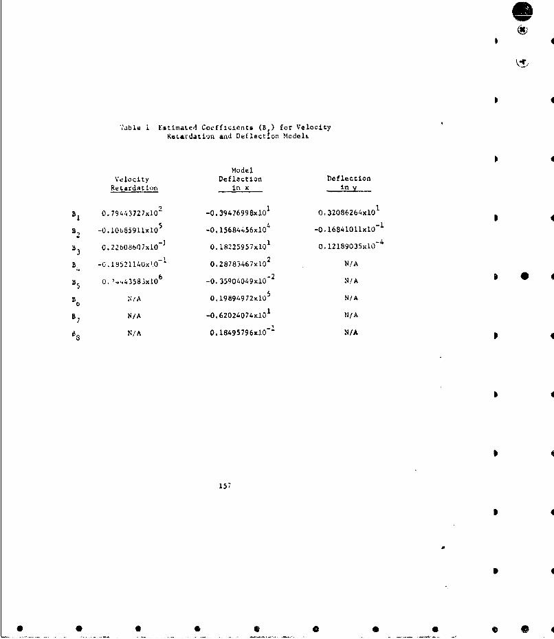
0
':able I Estimated Coefficients (B ) for VelocityRetardation and Deflection Models.
ModelVelocity Deflaction DeflectionRetardation in x -in x
B1 0.79443727xi0 2 0.39476998xlO 1 0.32086264x101
B, -0.10u53591b10l -.-O15684456x10"4 -0.16841011x101
83 0.22b608607x10- 0.18225957xl01 0.12189035x1 0-
B -0.18521140x10O 0.28783467x10 2 N/A
85 O.t1p.43583x10 6 -0.35904049x10-
2 N/A0
B. N/IA 0.19894972xlO N/Ab
B 7 N/A -0.620240740lO N/A
6N/A 0.1849579640 - N/A
157

Table 2 Input Paremeters for Brush Penetration Program
Symbol Parameter Units
Vs Striking velocity meters/second
D Depth of titi Metera
o Density of citi grams/cubic cencimeters
Projectile weight grzms
PD Projectile diameter milimeters
ES Striking energy joules
158
• • • •Q •S
Ie.__REFRLCCES
"InLtrior BoiI~ti at Guns", En ineering DeSign Handbook, BallistecsSuri.s, AŽICi' 70t-150, HQ, U. S. Acmy Material Command, February 1965.
2. McShane. E.J., Kelley, J.L. aod Reno, F.V., Exterior Ballistics, TheUniversity ot Denver Press, Denver, Colorado, 1953.
3. K~nmo.rov, A.N. and Fomin, S.V., "Elements of Theory of Functions andFunctrxnal Ar'alysis", Garylock Press, Rochester, N.Y., 1957.
4. Gross, Jr., W.E., "Exposure to Air Burst Weapons of Occupants of FiveSpecific Typei of Defense of Infantry Positions", (U), Army BallisticResearch Labcratories, Memorandum Report 1067, March 3957 (Confidential).
5. Fallin, H.K., "Analysi.0 of Machine Gun Burst Dispersion Data withCorresponding Effectiveness tHode!:, AMSAA TM-33, Aberdeen PcovingGround, Maryland, July 1969.
6. Mood, Alexander M. and Greybill, Franklin A., Introduction to theTheory of S':atistics, McGraw-Hill, New Nork, 2nd Edition, 1963.
7. Letter, A-MSAA, A.MXRD-AMD, to Frankford Arsenal, 21 August 1970,Subjece: Eglin AFB Test Firings.
S8. Hung, H.M. and Wong, J.T., "On the Kinematic Probability of TerminalBallistics with Initial Dispersion", SY-R3-70, Systems AnalystsDlreý.torate, Army Weapons Command, Rock Island, Illinois, September 1970.
9. CLrr, R.E. and Carroll, M.N., "Effectiveness of Existing and Hypo-clheiual 12 Gage Shot Guns", (U) Army Ballistic Research Laboratories,TN- 1 557, Aberdeen Proving Ground, Maryland, January 1965, (Secret).
10. Breaux, T.H., Campbell, L.W. and Torrey, J.C., "Statistical MultipleRegression Statistical Theory and Computer Program, Army BallisticResearch Laboratories, TN-1330, Aberdeen Proving Ground, Maryland,July 1966.
11. Table oa Salvo Kill Probabilities for Square Targets, U. S. Departmentof Conmmerce, National Bureau of Standards, Applied Mathematics Series44, December 20, 1954. 3
159
4
I
Ii
S
* 0 0 00 0


![Mathematical Models in Biology - Bio · PDF fileMathematical Models in Biology ... J.D., Mathematical Biology, Springer, 1989, [19] Edelstein-Keshet, Leah, Mathematical models in biology,](https://static.fdocuments.net/doc/165x107/5ab3fe3b7f8b9a7c5b8b587a/mathematical-models-in-biology-bio-models-in-biology-jd-mathematical-biology.jpg)