
ILLUSTRATION SAMPLES - M3 TechnicalILLUSTRATION SAMPLES. The M3 Group m3technical.com (312) 386-7413...
16
The M3 Group m3technical.com (312) 386-7413 ILLUSTRATION SAMPLES
Transcript of ILLUSTRATION SAMPLES - M3 TechnicalILLUSTRATION SAMPLES. The M3 Group m3technical.com (312) 386-7413...

The M3 Groupm3technical.com(312) 386-7413
ILLUSTRATION SAMPLES

The M3 Group m3technical.com (312) 386-7413
Shaded Line Illustrations
BAKING CENTER

The M3 Group m3technical.com (312) 386-7413
Shaded Line Illustrations
START
FILL
ALARM�MUTE
STOP
HEAT
BOOSTER�HEAT

The M3 Group m3technical.com (312) 386-7413
Line Illustrations
Tank Section
Heating Element
Gasket
ElectricalConnections
Remove bolts (4)
OFFON
OFFON
Loosenfitting
GasSolenoid
Valve
Removenipple
Removefitting &nipple

The M3 Group m3technical.com (312) 386-7413
Line Illustrations
Screw
Condenserfan bracket
CondensercoilCondenser
cover
LongCurtain
ShortCurtain
UpperTrack Guides

The M3 Group m3technical.com (312) 386-7413
Removescrews
Unload Rear GuardAccess Panel
ConveyorStop Bar
Removescrews
Line Illustrations

The M3 Group m3technical.com (312) 386-7413
Color Line Illustrations
Driven Gear Driver Gear
Pinion
Center Distance = C
Outside Diameter=0
Outside Diameter=0
Gear
Press Foot
Flywheel
Connecting Rod
11

The M3 Group m3technical.com (312) 386-7413
Exploded Illustrations
21 20 19
17
18 22 23 24 11
12 7 10
127
13
8 9
4 2 36 5
16 26 25 1514

The M3 Group m3technical.com (312) 386-7413
Exploded Illustrations
32 36 37
30
38
35 34 39 40 41 33 35 52
31 28 29 2829
53 49 50
51
42 45435554 48 43 46 47

The M3 Group m3technical.com (312) 386-7413
Exploded Illustrations
A
BCD
E
F
H
I
G
JK
VH1066
The M3 Group m3technical.com (312) 386-7413
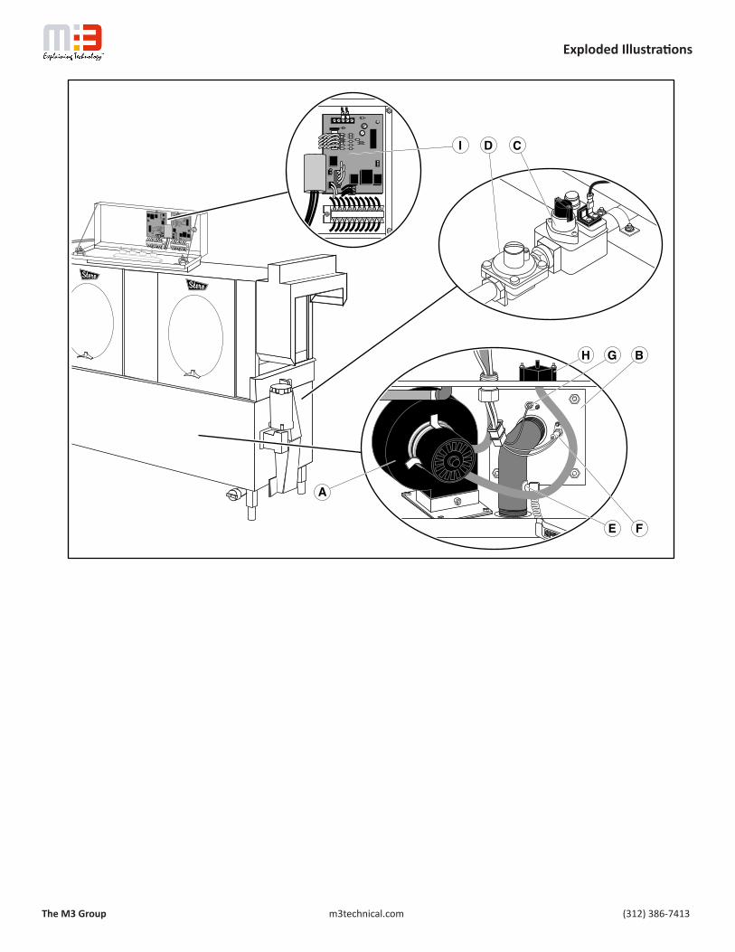
Exploded Illustrations
OFFON
D C
A
H G B
E F
I

The M3 Group m3technical.com (312) 386-7413
Illustructions

The M3 Group m3technical.com (312) 386-7413
Illustructions
2 GAL.CLEANINGSOLUTION

The M3 Group m3technical.com (312) 386-7413
Illustructions
Co
nn
ect AC
po
wer.
START
FILL
ALARM
MU
TE
STOP
HEAT
BOOSTERHEAT
START
FILL
ALARM
MU
TE
STOP
HEAT
BOOSTERHEAT
6
4
Rem
ove co
ver pan
el.A
ttach d
ish tab
les.
Co
nn
ect drain
.
Co
mp
ly with
all Plum
bin
g an
d Electrical
Co
des.
This ap
plian
ce must b
e con
nected
to a
gro
und
ed m
etal, perm
anen
t wirin
g
system, o
r an eq
uipm
ent-g
roun
din
g
con
ducto
r must b
e run w
ith th
e circuit co
nd
uctors an
d co
nn
ected to
the eq
uipm
ent-
gro
und
ing
termin
al or lead
on
this ap
plian
ce.
HO
T • 3/4" w
ater lineW
ATER
• 140F m
inimum
• 20 to 25 PSI
AC
• 1/2" EM
T - 8 AWG
wire
POW
ER
• 208/240/440 VAC
• To connect, access control box from
front.
• Ensure motors turn in designed direction.
DRA
IN
• 2" drain line – Cap one end.
• C
onnect one end to drain line.
• Position outlet above floor drain.
3
7
OR
Positio
n an
d level
wash
er.
12
5
Co
nn
ect ho
t water.
Co
nn
ect AC
po
wer.
START
FILL
ALARM
MU
TE
STOP
HEAT
BOOSTERHEAT
START
FILL
ALARM
MU
TE
STOP
HEAT
BOOSTERHEAT
6
4
Rem
ove co
ver pan
el.A
ttach d
ish tab
les.
Co
nn
ect drain
.
Co
mp
ly with
all Plum
bin
g an
d Electrical
Co
des.
This ap
plian
ce must b
e con
nected
to a
gro
und
ed m
etal, perm
anen
t wirin
g
system, o
r an eq
uipm
ent-g
roun
din
g
con
ducto
r must b
e run w
ith th
e circuit co
nd
uctors an
d co
nn
ected to
the eq
uipm
ent-
gro
und
ing
termin
al or lead
on
this ap
plian
ce.
HO
T • 3/4" w
ater lineW
ATER
• 140F m
inimum
• 20 to 25 PSI
AC
• 1/2" EM
T - 8 AWG
wire
POW
ER
• 208/240/440 VAC
• To connect, access control box from
front.
• Ensure motors turn in designed direction.
DRA
IN
• 2" drain line – Cap one end.
• C
onnect one end to drain line.
• Position outlet above floor drain.
3
7
OR
Positio
n an
d level
wash
er.
12
5
Co
nn
ect ho
t water.

The M3 Group m3technical.com (312) 386-7413
Illustructions

The M3 Group m3technical.com (312) 386-7413


