ILLUSTRATED ASSEMBLY MANUAL H7000IP-1 - … · ILLUSTRATED ASSEMBLY MANUAL H7000IP-1 ... These...
12
SIGNAL TRACER / INJECTOR KIT K7000 ILLUSTRATED ASSEMBLY MANUAL H7000IP-1 Total solder points: 85 Difficulty level: beginner 1 2 3 4 5 advanced Sim p l ifi es a ud i o t r o u bl e shoo ting.
Transcript of ILLUSTRATED ASSEMBLY MANUAL H7000IP-1 - … · ILLUSTRATED ASSEMBLY MANUAL H7000IP-1 ... These...

SIGNAL TRACER / INJECTOR KIT
K7000
ILLUSTRATED ASSEMBLY MANUAL H7000IP-1
Total solder points: 85 Difficulty level: beginner 1 2 3 4 5 advanced
Simplifies audio troubleshooting.

VELLEMAN NV Legen Heirweg 33
9890 Gavere Belgium Europe
www.velleman.be www.velleman-kit.com

3
Features This signal tracer /injector has been designed to inject or detect a specific signal into an audio circuit in need of repair (such as amplifiers, radios, tone controls, ...) so as to detect the fault. In this way problems can be traced more easily. The signal tracer may also be used as a simple monitor or amplifier. Specifications : Output power: 0.5W / 8ohm Power supply: 7-9VAC or 9-12VDC / 150mA Dimensions: 60 x 53mm (2.4" x 2.1") Injector:
0-2.5Vrms output (adjustable) Output impedance: 1.5Kohm Frequency: ± 1kHz
Tracer:
3.5mV to 10Vrms sensitivity (adjustable) Gain: 40dB Input impedance: 50Kohm
Features & Specifications

4
Assembly hints
1. Assembly (Skipping this can lead to troubles ! ) Ok, so we have your attention. These hints will help you to make this project successful. Read them carefully. 1.1 Make sure you have the right tools: A good quality soldering iron (25-40W) with a small tip.
Wipe it often on a wet sponge or cloth, to keep it clean; then apply solder to the tip, to give it a wet look. This is called ‘thinning’ and will protect the tip, and enables you to make good connections. When solder rolls off the tip, it needs cleaning.
Thin raisin-core solder. Do not use any flux or grease.
A diagonal cutter to trim excess wires. To avoid injury when cutting excess leads, hold the lead so they cannot fly towards the eyes.
Needle nose pliers, for bending leads, or to hold components in place.
Small blade and Phillips screwdrivers. A basic range is fine.
For some projects, a basic multi-meter is required, or might be handy
1.2 Assembly Hints :
Make sure the skill level matches your experience, to avoid disappointments. Follow the instructions carefully. Read and understand the entire step before you perform each operation. Perform the assembly in the correct order as stated in this manual Position all parts on the PCB (Printed Circuit Board) as shown on the drawings. Values on the circuit diagram are subject to changes. Values in this assembly guide are correct* Use the check-boxes to mark your progress. Please read the included information on safety and customer service
* Typographical inaccuracies excluded. Always look for possible last minute manual updates, indicated as ‘NOTE’ on a separate leaflet.
0.000

5
Assembly hints
1.3 Soldering Hints :
1- Mount the component against the PCB surface and carefully solder the leads
2- Make sure the solder joints are cone-shaped and shiny
3- Trim excess leads as close as possible to the solder joint
REMOVE THEM FROM THE TAPE ONE AT A TIME !
AXIAL COMPONENTS ARE TAPED IN THE CORRECT MOUNTING SEQUENCE !
You will find the colour code for the resistances and the LEDs on our website: http://www.velleman.be/common/service.aspx
6
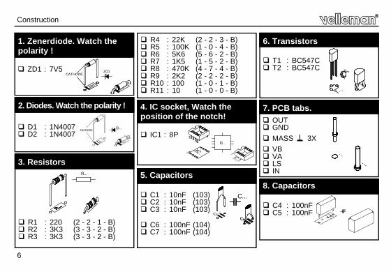
R1 : 220 (2 - 2 - 1 - B) R2 : 3K3 (3 - 3 - 2 - B) R3 : 3K3 (3 - 3 - 2 - B)
3. Resistors R...
Construction
D1 : 1N4007 D2 : 1N4007
2. Diodes. Watch the polarity !
D...CATHODE
ZD1CATHODE
ZD1 : 7V5
1. Zenerdiode. Watch the polarity !
R4 : 22K (2 - 2 - 3 - B) R5 : 100K (1 - 0 - 4 - B) R6 : 5K6 (5 - 6 - 2 - B) R7 : 1K5 (1 - 5 - 2 - B) R8 : 470K (4 - 7 - 4 - B) R9 : 2K2 (2 - 2 - 2 - B) R10 : 100 (1 - 0 - 1 - B) R11 : 10 (1 - 0 - 0 - B)
IC1 : 8P
4. IC socket, Watch the position of the notch!
C1 : 10nF (103) C2 : 10nF (103) C3 : 10nF (103)
C6 : 100nF (104) C7 : 100nF (104)
C...
5. Capacitors
OUT GND
MASS 3X
VB VA LS IN
7. PCB tabs.
T1 : BC547C T2 : BC547C
6. Transistors
C4 : 100nF C5 : 100nF
8. Capacitors

7
Construction
C8 : 1µF C9 : 1µF
C10 : 47µF
C11 : 100µF C12 : 100µF C13 : 100µF
C14 : 470µF
9. Electrolytic Capacitor. Watch the polarity !
C...
RV1 : 4K7 LIN RV2 : 47K LIN
10. Potentiometers.
RV...
IC1 : LM386
11. IC. Watch the position of the notch!

8
Test & Usage
Connect a test flex (preferably screened) to the in- and output (marked OUT, IN). Turn the potentiometers to their minimum position (completely to the left). Connect a loudspeaker (min 4 ohm 0,5W) to output LS and earth. Connect either a transformer ( 2 X 7- 9VAC) to points VA and VB (fig 1.0), with its centre branching to earth, or a 9V battery with its plus pole to VA or VB and its minus pole to earth (fig 2.0). Disconnecting the power supply can be achieved using a switch (in the plus connection when using a battery, in the mains connection when using a transformer). To test the circuit, connect the output test flex to the input test flex. When you now turn both potentiometers, an audible test signal should come out of the loudspeaker, at least when everything is working all right.
12. TEST & USAGE
RV1
RV2
Fig. 1.0

9
Testing
Fig. 1.0
Usage : Connect the earth of the signal generator/tracer to the earth of the circuit to be tested (to do so you may
use one of the screens of the test flexes). Now you can "detect" or "inject" a signal at certain points of the circuit (e.g. the base of a transistor) so as
to locate the defective component.
Fig. 2.0

10
13. PCB
PCB

11
Diagram
14. DIAGRAM

Modifications and typographical errors reserved © Velleman nv. H7000IP - 2014 - ED1 (rev.1.0) 5 4 1 0 3 2 9 4 2 8 7 6 1
VELLEMAN NV Legen Heirweg 33, B-9890 GAVERE
Belgium (Europe)


![No Title · 2018-12-19 · Title: Size: Reference: Date: Sheet: of A4 Rev ision: P roject: NUCLEO-X X X X RX C23 100nF C28 100nF C24 100nF C34 20pF [N/A] C33 20pF [N/A] X3 8MHz(16pF](https://static.fdocuments.net/doc/165x107/5ec8c1ad23a49b207e3946b4/no-title-2018-12-19-title-size-reference-date-sheet-of-a4-rev-ision-p-roject.jpg)