Illustra Pro Series Configuration Guide
137
Illustra Flex 2MP 20x PTZ lllustra Pro 12MP Fisheye Illustra FlexZ Mini dome Configuration Guide 8200-1307-01 C0
Transcript of Illustra Pro Series Configuration Guide

Illustra Flex 2MP 20x PTZ
lllustra Pro 12MP Fisheye
Illustra FlexZ Mini dome
Configuration Guide
8200-1307-01 C0

Notice
The information in this manual was current when published. The manufacturer reserves the right to revise and improve its products. Allspecifications are therefore subject to change without notice.
CopyrightUnder copyright laws, the contents of this manual may not be copied, photocopied, reproduced, translated or reduced to any electronicmedium or machine-readable form, in whole or in part, without prior written consent of Tyco Security Products.
© 2016 Tyco Security Products. All Rights Reserved.
Tyco Security Products
6600 Congress Avenue
Boca Raton, FL 33487 U.S.A.
Customer ServiceThank you for using Illustra products. We support our products through an extensive worldwide network of dealers. The dealer throughwhom you originally purchased this product is your point of contact if you need service or support. Our dealers are empowered to provide thevery best in customer service and support. Dealers should contact Tyco Securitry Products s at (800) 507-6268 or (561) 912-6259 or on theWeb at www.illustracameras.com.
TrademarksWindows® is a registered trademark of Microsoft Corporation. PS/2® is a registered trademark of International Business MachinesCorporation.
The trademarks, logos, and service marks displayed on this document are registered in the United States [or other countries]. Any misuse ofthe trademarks is strictly prohibited and Tyco Security Products will aggressively enforce its intellectual property rights to the fullest extent ofthe law, including pursuit of criminal prosecution wherever necessary. All trademarks not owned by Tyco Security Products are the propertyof their respective owners, and are used with permission or allowed under applicable laws.
Product offerings and specifications are subject to change without notice. Actual products may vary from photos. Not all products include allfeatures. Availability varies by region; contact your sales representative.
2

Introduction 6
Illustra Connect 7
Discovering the Illustra Camera 8
Using the Camera Controls 9
Controlling the Camera via Camera Controls 10
Web Configuration 12
Prerequisites 12
Accessing the Camera Web GUI 12
Accessing the Setup Menus from Live View 14
Displaying the Live View Page 14
GUI Icons 15
Video Pane 16
Quick Start Menu 17
TCP/IP 18
Video Stream Settings 19
Picture Basic Tab 20
Picture Basic Settings on the Flex PTZ Camera 20
Picture Basic Settings on the Pro Fisheye Camera 24
Picture Basic Settings on the FlexZ Camera 26
Focus and Zoom Settings on the FlexZ Camera 28
Exposure Settings on the FlexZ Camera 29
Picture Additional Menu 31
Picture Additional Settings on the Flex PTZ camera 31
Picture Additional Settings on the Pro Fisheye camera 35
Picture Additional Settings on the FlexZ camera 40
Lens Calibration 45
Date/Time/OSD 46
PTZ Settings Menu 48
PTZ Parameters 49
Preset 49
Patterns 52
Configuration Guide 3

Scans 54
Sequences 57
Home 59
Video Menu 61
Streams 62
Configuring the Video Stream Settings 62
Camera 63
Picture Basic Tab 65
Picture Basic Settings on the Flex PTZ Camera 65
Picture Basic Settings on the Pro Fisheye Camera 69
Picture Basic Settings on the FlexZ Camera 72
Focus and Zoom Settings on the FlexZ Camera 73
Exposure Settings on the FlexZ Camera 74
Picture Additional Menu 76
Picture Additional Settings on the Flex PTZ camera 76
Picture Additional Settings on the Pro Fisheye camera 81
Picture Additional Settings on the FlexZ camera 86
Lens Calibration 91
Date/Time/OSD 92
Privacy Zones 94
Events and Actions Menu 97
Event Settings 98
FTP 99
Event Actions 101
Analytics 105
Event Logs 107
Security 109
Users 110
HTTP/HTTPS 112
IEEE 802.1x 113
Network Menu 117
4
TCP/IP 118
FTP 119
SMTP 120
Dynamic DNS 123
System 125
Maintenance 126
Backup/Restore 128
Date/Time 129
Audio 130
TV System 131
Logs 131
About 132
Edge Recording 134
SD Card Management 135
Features Available with a SD Card or microSD Card 135
Without a SD Card or microSD Card 135
Record Settings 137
Event Download 137
Configuration Guide 5

IntroductionThe Illustra series cameras are high definition cameras utilizing the latest in IP technologies. ONVIF-compatibilityallows interoperability with other ONVIF-compliant third party NVRs. A built-in web server allows you to configurethe camera and stream video using Internet Explorer version 10 and higher.
Although the camera can operate as a standalone camera on a network, it is intended to be integrated intosophisticated security solutions.
Please refer to the Illustra Cameras website (www.illustracameras.com) to ensure that you have the most currentversion of this Configuration Guide. Release Notes are also available on the website for each software release todocument any known limitations not covered in this user guide.
The models of camera listed below are covered by this configuration guide:
Illustra Flex Model Description Product Codes
Illustra Flex 2MP 20x PTZ indoor, white, TDN, WDR IFS02P5ICWTY
Illustra Flex 2MP 20x PTZ outdoor, white, TDN, WDR IFS02P5OCWTY
Illustra Fisheye Model Description Product Code
Illustra Pro 12 MP Fisheye, indoor/outdoor, white TDN w/IR, WDR IPS12FFOCWIY
Illustra FlexZ Model Description Product Codes
Illustra FlexZ 3MP indoor mini dome, no IR IF03DITPZ
Illustra FlexZ 3MP outdoor mini dome with IR IF03DOTPZ
Accessing the Camera for the First Time
Step Action
1 Make appropriate network and power connection (typically PoE+ for PTZ units).
The camera will automatically get an IP address if connected to a DHCP network. If DHCP addressingis not available, the camera will use its default fixed address: 192.168.1.168.
2 Find camera(s) on the network using Illustra Connect or another utility; or if using fixed addresses,connect to the camera on its default address.
3 Enter the default ID and password when prompted—ID: admin, Password: admin.
4 Select Log in.
The Live view page will be displayed.
8200-1307-01 C0

Note:
If you are using an IE browser, the PC requires a Sensormatic plug-in to display Live view. If the PC doesnot have the plug-in installed the web browser prompts the user for permission to install the plug-in. Oncethe permission is granted, the browser downloads the plug-in from the camera , and the live viewdisplays.
5 To maintain security a popup page will display and prompt you to change the default password to apassword of your own choosing. Enter the old password, your new password and confirm your newpassword in the correct fields. You are also required to select what language the GUI appears in. Selectthe language of your choice from the dropdown menu.
6 Select Apply to save your settings.
Figure 1-1 Security popup screen
Illustra ConnectIllustra Connect is the camera discovery tool created by Tyco Security Products and can be downloaded atillustracameras.com.
Connecting to IP cameras and configuring them can be a time-consuming and error-prone process. Typing staticIP addresses, or naming cameras without seeing where they are pointed, often results in longer installations.Illustra Connect eliminates all of these issues with a unique feature set that includes a one-touch IP conflictresolver and snapshot tool . Simply bring up all of the cameras out of the box, enter the IP range provided by thecustomer's IT department and click OK.
Key functions of Illustra Connect are:• Resolve All Conflicts button provides two options to fix conflicted IP addresses. You can set all
conflicting cameras to DHCP or assign a static IP address within a certain range, for example:192.168.185.100 to 192.168.185.110
• Snapshot views of all the cameras
• Save Device List allows you to create a .csv file of all information regarding the camera settings
• Set IP addresses via DHCP
7

• Configure IP settings and rename cameras
• Upload firmware to individual or selectable group of cameras
• Set date and time or direct the cameras to a specific NTP server
• Assign user name and password
Discovering the Illustra CameraThe following provides detailed information for installing and accessing the camera.
Illustra ConnectThe following provides information for installing the camera on your network using the Illustra Connect discoverytool.
Illustra Connect enables automatic discovery of devices on IP networks and is the recommended method forinstallation and detection of the camera on the network.
Discovering the Illustra Camera using Illustra Connect
Step Action
1 Connect the camera to the computer or network which will be used for the configuration and power on.The camera will begin its initial boot up sequence which will take approximately 1 to 2 minutes. Out of thebox, or when using a DHCP Server, the camera will automatically be assigned a Network IP address.
2 Install the Illustra Connect software that is provided with the camera. Refer to the Illustra Connectmanual for more information.
3 When the installation is complete, run Illustra Connect. It will search the network and display all devices.
4 Select the camera you wish to configure, locating it by its unique MAC address. Illustra Connect allowsbasic configuration of the camera. Refer to the Illustra Connect manual for more information.
5 Right-click the camera and select Launch Web GUI Configuration.
- End -
Installing the Illustra Camera using DHCP Server Logs
Step Action
1 Connect the camera to the computer or network which will be used for the configuration and power on.The camera will begin its initial boot up sequence which will take approximately 1 to 2 minutes.
2 Out of the box or when using a DHCP Server the camera will automatically be assigned a Network IPAddress.
3 View the DHCP Server system logs and make note of the IP address assigned to the camera.
4 Open Microsoft Internet Explorer and enter the URL of the camera as shown in the DHCP Server log.Note:
At factory default, after enabling DHCP manually or if it is the first time the camera has been configured; thecamera will reboot using the Failover of the last known static IP address until a DHCP address request isauthorised by the DHCP server. The DHCP requests will remain active unless cameras are changed to Static IP.
Configuration Guide 8

Configuring the Illustra Camera using a Static IP AddressThe following information states how to install the camera on your network when no DHCP Server is available. Inthis situation the camera will be assigned a Static IP address.
Connect the camera to the computer or network which will be used for the configuration and power on.Note:
• We recommend that once you are logged into the Web Configuration pages you change the Static IPaddress of the camera so that conflicts can be avoided when using the same Static IP address to setupadditional cameras.
• In a situation where IP address conflicts arise, Illustra Connect can be used to discover the device.
UPnP DiscoveryUniversal Plug and Play discovery broadcasts information about the camera to other devices on the network.
The feature broadcasts:
• Device names
• Manufacturer URL
• Device model
• Serial number
• MAC address
• Unique identifier
• IP address
The feature supports HTTP and HTTPS
Using the Camera Controls• You can use the on-screen controls in the Live Video Pane to control the camera
• The camera will have varying levels of PTZ capability depending on which model you are using
PTZ Camera ControlsThe following diagram provides information on the controls available for on-screen camera control. The cameracontrol overlay is visible when video is displayed on the Live Video Pane.Note:
The camera will have varying levels of PTZ capability depending on which model you are using.
The Fisheye features virtual PTZ functionality on the active image sources.
9

Figure 1-2 PTZ Camera Controls
Note:
• It is possible for two users to access live viewing at the same time. However only one user maycontrol the camera at any time. Camera control operates on a "last come, first served" basis.Therefore, when a new user logs into the camera from a different browser and starts a cameracontrol session, the original user will lose their camera control session.
• The Fisheye camera does not support focus and iris adjustment via ptz controls.
Controlling the Camera via Camera ControlsYou can use the on-screen controls in the Live Video Pane to control the camera.Note:
The camera will have varying levels of PTZ capability depending on which model you are using.
The Fisheye features virtual PTZ functionality (eptz).
Controlling the Camera via the Live Video Pane
Step Action
1 Select to start the live web video.
The live video pane will display the current camera view.
2 Select the camera control item on the overlay to activate the control.
Configuration Guide 10

Controlling the Pan/Tilt Control via Click and DragYou can use the mouse to control the camera, allowing slower camera movement and maximum accuracy.Note:
The camera will have varying levels of PTZ capability depending on which model you are using.
The Fisheye features a virtual PTZ functionality using ActiveX plugin in Internet Explorer.
Controlling Pan/Tilt via Click and Drag using the Live Video Pane
Step Action
1 Select to start the live web video.
The live video pane will display the current camera view.
2 Click and drag the cursor to set the direction and speed of the camera.
• A red arrow will appear showing the direction of camera movement.
• The camera’s movement speed increases as the arrow is moved further from the cursor originmark.
- End -
Zooming Using the Mouse Scroll WheelYou can control the zoom function using a scroll wheel mouse.
Zooming via the Mouse Scroll Wheel Using the Live Video Pane
Step Action
1 Select to start the live web video.
The live video pane will display the current camera view.
2 While the cursor is over the Live Video Pane, scroll the mouse wheel upwards (zoom in) and downwards(zoom out).
- End -
11

Web ConfigurationThis section details how to configure the camera settings.
Prerequisites• Adobe Reader must be installed to view the online help.
• If using Internet Explorer, an ActiveX installer must be installed. If using any other browser, the latestversion of QuickTime player including web plugin must be installed.
• Only users with administrative rights can access all the areas of the Web Configuration pages.
Accessing the Camera Web GUIProcedures in relation to accessing the camera web GUI, are included below.
Logging in to the CameraUse the following procedure to access the camera.
Log in to the Camera
Step Action
1 Refer to Introduction if it is your first time logging in to the camera.
2 Rightclick on the camera icon and select Launch Web GUI3 When the camera is selected the sign in page will be displayed.
4 Select Log in.
The Live view page will be displayed.
5 Enter theUsernameThe default is 'admin'.6 Enter thePassword. The default is 'admin'.
7 To maintain security a popup page will display and prompt you to change the default password to apassword of your own choosing. Enter the old password, your new password and confirm your newpassword in the correct fields. Select your preferred language from the drop-down menu. The defaultlanguage is ‘English’.
8 Select Apply to save your settings.
Configuration Guide 12

Figure 2-1 Security popup screen
- End -
Logging out of the CameraUse the following procedure to log off the camera Web GUI:
Select Log Off in the upper right hand corner of the Web GUI.
You will be logged off the camera and sign in page will be displayed.
- End -
Changing the Camera Web GUI LanguageUse the following procedure to change the language used in the camera web GUI
Change the Camera Web GUI Language
Step Action
1 Select Setup on the GUI banner to display the setup menus.
2 Select Language option on the above left of the screen. A dropdown menu will appear.
3 Select your preferred language from the drop-down menu:
• English (American)• Arabic• Czech• Danish• German• Spanish• French• Hungarian• Italian
13

• Japanese• Korean• Dutch• Polish• Portuguese (Brazilian)• Swedish• Turkish• Chinese Simplified• Chinese Traditional• Russian
The default language is `English`.
The camera Web GUI will be displayed in the selected language.
- End -
Accessing the Setup Menus from Live ViewWhen displaying full screen live video select Setup on the GUI banner to access the setup menus.
Displaying the Live View PageDisplay the live camera view page.
Display Live View Page
Step Action
1 Select Live in the GUI banner.
The live view page will be displayed.
2 Select a video stream from Stream to view:
The default setting is ‘Stream 1’
3 Select a percentage from Scale to change the display size of the video pane:
• 25%• 50%• 75%• 100%
The default setting is ‘50%’
- End -
Configuration Guide 14

GUI IconsThe following provides information on the icons used throughout the camera interface. These icons will bereferenced throughout this manual:
Select to start streamingvideo to the video pane.
Select to stopstreaming videoto the video pane.
Check box, deselected. Check box,selected.
Delete the correspondingfunction.
Refresh thecurrent tab.
View or activate thecorresponding function.
Edit thecorrespondingfunction.
Hide the active tab details. Unhide the activetab details
Enable the microphone.
Increase ordecrease volumeby clicking theicon anddragging volumeup or down.Clickthe icon once tomute or unmutethe volume.
Enable standard FisheyeImage view
Enable FisheyeActive Image(eptz) view
Enable Wall Panoramic(180° view)
Enable CeilingPanoramic (360°view)
Enable Combi image view:1x 180° panoramic & 2xActive Images (2eptz)
Enable Combiimage view: QuadActive Image(4eptz)
Enable standard Flex Imageview
Enable whichFlex camera viewis desired byselecting theradio button nextto it
Slider bar - The slider bar can be moved left or right using themouse. For fine adjustments, select the slider bar with themouse and use the left and right arrow keys on the PCkeyboard to adjust the slider.
15
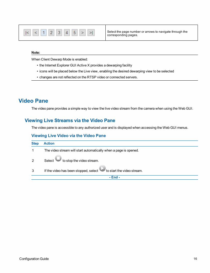
Select the page number or arrows to navigate through thecorresponding pages.
Note:
When Client Dewarp Mode is enabled:
• the Internet Explorer GUI Active X provides a dewarping facility
• icons will be placed below the Live view, enabling the desired dewarping view to be selected
• changes are not reflected on the RTSP video or connected servers.
Video PaneThe video pane provides a simple way to view the live video stream from the camera when using the Web GUI.
Viewing Live Streams via the Video PaneThe video pane is accessible to any authorized user and is displayed when accessing the Web GUI menus.
Viewing Live Video via the Video Pane
Step Action
1 The video stream will start automatically when a page is opened.
2 Select to stop the video stream.
3 If the video has been stopped, select to start the video stream.
- End -
Configuration Guide 16

Quick Start MenuWhen the Quick Start menu is selected, Figure 3-1 Basic Configuration Menu will be displayed.
Note:
When an admin user logs in for the first time the Basic Configuration page is displayed. After this, on each loginthe Video > Streams page will be displayed.
Figure 3-1 Basic Configuration Menu
The Basic Configuration menu provides access to the most common features required when setting up a camerafor the first time and is only available to an ‘admin’ user. The following tabs are displayed:
• TCP/IP
• Stream
• Picture Basic
• Picture Additional
• Lens Calibration
• Date/Time/OSD
8200-1307-01 C0

TCP/IPConfigure the IPv4 and IPv6 network settings on the camera.
IPv4Configure the IPv4 network settings for the camera.
Configure the IPv4 Settings
Step Action
1 Select Setup on the GUI banner to display the setup menus.
2 Select the TCP/IP tab in theQuick Start Basic Configuration menu.
3 Select theEnable DHCP check box to enable DHCP (Dynamic Host Configuration Protocol) anddisable manual settings.
OR
Deselect Enable DHCP to disable DHCP and allow manual settings to be entered.
The default setting is 'Enabled’.
4 If Enable DHCP has been disabled:
a Enter the IPv4 Address in the IPv4 Address text box in the form xxx.xxx.xxx.xxx.The default setting is ‘192.168.1.168’ .
b Enter theNetwork Mask in the Network Mask text box xxx.xxx.xxx.xxx.The default setting is ‘255.255.255.0’.
c Enter theGateway IP address in Gateway text box xxx.xxx.xxx.xxx.The default setting is192.168.1.254.
d Enter thePrimary DNS Server in the Primary DNS Server text box xxx.xxx.xxx.xxx. The defaultsetting is 0.0.0.0.
5 Select Apply to save the settings.
- End -Note:
If the camera has been configured with a static IP and DHCP is enabled, the camera will continue to use the setstatic IP until the DHCP is set and a new IP has been assigned.
IPv6Enable or disable IPv6 on the camera.
Enable/Disable IPv6
Step Action
1 Select Setup on the GUI banner to display the setup menus.
18

2 Select the TCP/IP tab in theQuick Start Basic Configuration menu.
3 Select the IPv6 Enable check box to enable IPv6 on the camera.
OR
Deselect the IPv6 Enable check box to disable IPv6 on the camera.
The default setting is ‘Enabled’.
- End -
Video Stream SettingsThe camera allows the configuration of up to three video streams. These streams can be configured via the WebGUI, as detailed here, or via the Illustra API.
Opening the Web GUI live video will allow the stream to be shared with the Illustra API and will minimize theimpact on camera resources.
Configuring the Web Video StreamAdjust the settings for each video stream.
Configure the Video Stream Settings
Step Action
1 Select Setup on the GUI banner to display the setup menus.
2 Select theVideo tab and choose between the stream 1, 2, 3 tabs.
3 The selected stream displays.Note:
When using the Pro Fisheye camera:
• there will be a choice of image sources to be selected.The image source choices available willvary according to camera dewarp mode and mount option settings.
• the image selected in Stream 1 is shared between the other streams.
4 Select the requiredCodec by selecting the radio buttons:
• H264• MJPEG
5 Select the requiredResolution from the drop-down menu.The resolutions available will depend on the Image Source selected.
6 Use the slider bar to select the Frame Rate (fps).7 Use the slider bar to select theGroup of Pictures (GOP) length.
8 If MJPEG has been selected, MJPEG Quality will be enabled. Use the slider bar to select theMJPEGQuality.
OR
Configuration Guide 19

9 If H264 has been selected in step 4, Rate Control will be enabled. Select the requiredRate Control byselecting the radio buttons:
• VBR (Variable Bit Rate)• CBR (Constant Bit Rate)• CVBR (Constrained Variable Bit Rate)
The default setting is ‘VBR’.
If VBR has been selected, VBR Quality will be enabled. Select the requiredVBR Quality from the drop-down menu.
• Highest
• High
• Medium
• Low
• Lowest
The default setting is ‘High’.
OR
e If CBR has been selected, CBR Bit Rate will be enabled. Use the slider bar to select theCBR BitRate.
OR
f If CVBR has been selected, CVBR Quality and Bitrate will be enabled. Select the requiredCVBRQuality from the drop-down menu.
• Highest
• High
• Medium
• Low
• Lowest
The default setting is 'High'.
ANDUse the slider bar to select theCVBR Bit Rate.
- End -
Picture Basic TabOrientation, zoom and exposure settings are configured from the Picture Basics tab.
Picture Basic Settings on the Flex PTZ CameraThe Flex PTZ camera orientation and exposure settings may be configured to optimize visual quality.
Refer to Figure 3.2 when configuring the camera orientation and exposure settings on the Flex PTZ camera.
20

Figure 3-2 Picture Basic settings on Flex PTZ camera
Picture RotationThe Picture Rotation of the camera may be set to normal video or at 180 degrees.
Set Picture Rotation
Step Action
1 Select Setup on the GUI banner to display the setup menus.
2 Select thePicture Basic tab from theQuick Start Basic Configuration menu.
3 Select theOrientation check box to either:
• Normal video• 180 degree rotate
The orientation of the camera updates to the orientation you have selected on the live feed.
4 Select Apply to save your changes.
- End -
Configuration Guide 21

Max GainThe Max Gain setting increases or reduces picture noise.The trade-off between picture level (brightness) andnoise may be adjusted by enabling or disabling the Max Gain feature. Enabling the Max Gain settings may resultin a darker picture, but with less noise. Disabling the Max Gain settings may result in a brighter picture, but withmore noise.
Full Auto ModeIn this mode, the camera's shutter speed, iris and Auto Gain Control (AGC) circuits work together automatically tomaintain a consistent video output level.
Max Gain Setting Options: Full Auto, Shutter Priority, P-Iris, Iris Priority, andManual Mode
When Shutter Priority or Iris Priority are enabled, the camera automatically compensates for scene changes thataffect light levels .
In Shutter Priority Mode the iris is adjusted first to control the exposure. Then Gain can be adjusted.
In P-Iris mode the minimum iris opening is limited to minimize defraction.
In Iris Priority Mode the iris setting is fixed. The shutter speed is adjusted first to control the exposure. Then Gainis used when needed.
If Manual Mode is selected, users can adjust the shutter speed, Iris, and Gain settings manually.
Configure Exposure Settings
Step Action
5 Select Setup on the GUI banner to display the setup menus.
6 Select thePicture Basic tab from theQuick Start Basic Configuration menu.
7 Select to start the video stream if it is not already active.
8 Select Auto Mode check box to enable Auto Mode or deselect Auto Mode check box to disable AutoMode.
The default setting is disabled.
If Auto Mode has been selected in Step 4, Max Gain will be enabled.
9 Max Gain may be increased and decreased by selecting the desired setting from the dropdown menu.
10 The video pane will update to display the new settings.
11 Select Apply to save your changes.
- End -
Shutter PriorityEnable or disable Shutter Priority mode.
22

Enable/Disable Shutter Priority Mode
Step Action
1 Select Setup on the GUI banner to display the setup menus.
2 Select thePicture Basic tab from theQuick Start Basic Configuration menu.
3 Select theShutter Priority check box to enable Shutter Priority mode.
OR
Deselect theShutter Priority check box to disable Shutter Priority mode.
The default setting is ‘Disabled’.
4 The shutter time is configurable using the dropdown menu.
5 Select Apply to save your changes.
- End -
P-Iris ModeEnable or disable P-Iris mode.
Enable/Disable P-Iris Mode
Step Action
1 Select Setup on the GUI banner to display the setup menus.
2 Select thePicture Basic tab from theQuick Start Basic Configuration menu.
3 Select theP-Iris check box to enable P-Iris mode.
OR
Deselect theP-Iris check box to disable P-Iris mode.
The default setting is ‘Disabled’.
4 The maximum exposure time is configurable using the dropdown menu.
5 Select Apply to save your changes.
- End -
Iris-PriorityEnable or disable Iris Priority mode.
Enable/Disable Iris Priority Mode
Step Action
1 Select Setup on the GUI banner to display the setup menus.
2 Select thePicture Basic tab from theQuick Start Basic Configuration menu.
3 Select the Iris Priority check box to enable Iris Priority mode.
OR
Configuration Guide 23

Deselect the Iris Priority check box to disable Iris Priority mode.
The default setting is ‘Disabled’.
4 The maximum exposure time is configurable using the dropdown menu.
5 Select Apply to save your changes.
- End -
Manual ModeEnable or disable Manual Mode.
Enable/Disable Iris Manual Mode
Step Action
1 Select Setup on the GUI banner to display the setup menus.
2 Select thePicture Basic tab from theQuick Start Basic Configuration menu.
3 Select theManual check box to enable Manual mode.
OR
Deselect theManual check box to disable Manual mode.
The default setting is ‘Disabled’.
4 Select Apply to save your changes.
- End -
Configure Manual Mode Settings
Step Action
1 Select Setup on the GUI banner to display the setup menus.
2 Select thePicture Basic tab from theQuick Start Basic Configuration menu.
3 Select theManual check box to enable Manual mode.
4 Adjust the Shutter, Iris and Gain settings by selecting the desired settings from the dropdown menus.
5 Select Apply to save your changes.
- End -
Picture Basic Settings on the Pro Fisheye CameraThe Pro Fisheye camera exposure settings may be configured to optimize visual quality.
Refer to Figure 3.3 when configuring the camera orientation and exposure settings on the Flex PTZ camera.
24

Figure 3-3 Picture Basic settings on Pro Fisheye camera
Auto Shutter ModeIn this mode, the camera's shutter speed adjusts automatically to maintain a consistent video output level.
Manual ModeIn this mode the camera's shutter speed can be adjusted manually to attain the desired video output level.
Auto Shutter ModeEnable or disable Auto Shutter mode.
Manual ModeEnable or disable Manual Mode.
Enable/Disable Auto Shutter Mode
Step Action
1 Select Setup on the GUI banner to display the setup menus.
2 Select thePicture Basic tab from theQuick Start Basic Configuration menu.
3 Select theAuto Shutter check box to enable Auto Shutter mode.
OR
Deselect theAuto Shutter check box to disable Auto Shutter mode.
The default setting is ‘Enabled’.
4 Select Apply to save your settings.
- End -
Configuration Guide 25

Configure Auto Shutter Mode Settings
Step Action
1 Select Setup on the GUI banner to display the setup menus.
2 Select thePicture Basics tab from theQuick Start Basic Configuration menu.
3 Select theAuto Shutter check box to enable Auto Shutterl mode.
4 Adjust the Shutter speed by using the dropdwn menu to select the desired minimum shutter speed.
5 Adjust the Max Gain settings using the dropdown menu to select the desired value.
6 Select Apply to save your settings.
- End -
Enable/Disable Manual Mode
Step Action
7 Select Setup on the GUI banner to display the setup menus.
8 Select thePicture Basic tab from theQuick Start Basic Configuration menu.
9 Select theManual check box to enable Manual mode.
OR
Deselect theManual check box to disable Manual mode.
The default setting is ‘Disabled’.
10 Select Apply to save your settings.
- End -
Configure Manual Mode Settings
Step Action
1 Select Setup on the GUI banner to display the setup menus.
2 Select thePicture Basics tab from theQuick Start Basic Configuration menu.
3 Select theManual check box to enable Manual mode.
4 Adjust the Shutter speed by using the dropdwn menu to select the desired shutter speed.
5 Adjust the Gain settings using the dropdown menu to select the desired value.
6 Select Apply to save your settings.
Picture Basic Settings on the FlexZ CameraThe FlexZ camera orientation, zoom and exposure settings may be configured to optimize visual quality.
Refer to Figure 3.4 when configuring camera orientation,zoom and exposure settings for the FlexZ camera.
26

Figure 3-4 Picture Basic settings on FlexZ camera
Picture RotationThe Picture Rotation of the camera may be set to normal video or at 180 degrees.
Set Picture Rotation
Step Action
1 Select Setup on the GUI banner to display the setup menus.
2 Select thePicture Basic tab from theQuick Start Basic Configuration menu.
3 Select one of the followingOrientation check boxes:
Configuration Guide 27

• Normal video• Flip• 180 degree rotate• Mirror video
The orientation of the camera updates to the orientation you have selected on the live feed.
The default setting is 'normal video'.
4 Select Apply to save your changes.
- End -
Focus and Zoom Settings on the FlexZ CameraThe FlexZ camera focus and zoom settings may be configured to optimize focus and zoom quality.
The zoom settings can be configured by using the zoom slider bar to widen or narrow the zoom.
The Auto Focus mode may be set to manual mode or auto mode.
If the Manual option is selected, the zoom may be altered by using the One Touch button to refocus the camera tooptimal focus and zoom.
If the Auto mode is selected, the zoom will refocus automatically to optimise the quality of focus and zoom on theimage.
Widen/Narrow the Camera Zoom Setting
Step Action
1 Select Setup on the GUI banner to display the setup menus.
2 Select thePicture Basics tab from theQuick Start Basic Configuration menu.
3 Widen the zoom setting on the camera by dragging the Zoom slider bar to the left( towardWide).
OR
Narrow the zoom setting on the camera by dragging the slider bar to the right (toward Tele).
The updated zoom setting will display on the live feed.
4 Select Apply to save your settings.
- End -
Select AutoFocus Mode
Step Action
1 Select Setup on the GUI banner to display the setup menus.
2 Select thePicture Basics tab from theQuick Start Basic Configuration menu.
3 Select one of theAF Mode options by checking one of the checkboxes.
The options are:
• Manual
28

• Auto (for automatic focus adjustments at each zoom level change)4 Select Apply to save your settings.
- End -
Configure Manual AutoFocus mode
Step Action
1 Select Setup on the GUI banner to display the setup menus.
2 Select thePicture Basics tab from theQuick Start Basic Configuration menu.
3 Select theManual checkbox from the AF Mode options.
4 Select theOne Touch button.
The camera refocuses to the optimal zoom level for the image
OR
Use the plus and minus arrows at either side of theOne touchbutton to manually configure the focus andthe slider bar to adjust zoom settings until the image is at desired zoom/focus point.
5 Select Apply to save your settings.
- End -
Exposure Settings on the FlexZ CameraThe FlexZ camera exposure settings may be configured to optimize visual quality.
P-Iris Priority ModeIn this mode, the camera's iris size can be increased and decreased. The changes can be made manually or userscan select an option where the camera will automatically detect the best size for the environment.
Iris size, Gain and shutter speed settings can be configured manually in this mode.
Manual ModeIn this mode the camera's shutter speed and Gain aetting can be adjusted manually to attain the desired videooutput level.
Enable P-Iris Priority Mode
Step Action
1 Select Setup on the GUI banner to display the setup menus.
2 Select thePicture Basic tab from theQuick Start Basic Configuration menu.
3 Select theP-Iris Priority check box to enable P-Irris Priority mode.
The default setting is ‘Enabled’.
4 Select Apply to save your settings.
Configuration Guide 29

Configure P-Iris Priority Mode Settings
Step Action
1 Select Setup on the GUI banner to display the setup menus.
2 Select thePicture Basics tab from theQuick Start Basic Configuration menu.
3 Select theP-Iris Priority check box to enable P-Iris Priority mode.
4 Select the Auto Detect button and the camera automatically detect the best iris size for theenvironment. In addition, users can manually adjust the iris size by selecting the plus and minus buttonsto adjust the iris size further.
You can click on to reset the iris size. The iris size will reset to its largest size. Adjust he irissize settings until you are happy with the setting.
5 Adjust the shutter speed and gain settings using the dropdown menus
6 Select Apply to save your settings.
- End -
Enable Manual Mode
Step Action
7 Select Setup on the GUI banner to display the setup menus.
8 Select thePicture Basic tab from theQuick Start Basic Configuration menu.
9 Select theManual check box to enable Manual mode.
The default setting is ‘Disabled’.
10 Select Apply to save your settings.
- End -
Configure Manual Mode Settings
Step Action
1 Select Setup on the GUI banner to display the setup menus.
2 Select thePicture Basics tab from theQuick Start Basic Configuration menu.
3 Select theManual check box to enable Manual mode.
4 Adjust the Shutter speed by using the dropdwn menu to select the desired shutter speed.
5 Adjust the Gain settings using the dropdown menu to select the desired value.
6 Select Apply to save your settings.
- End -
30

Picture Additional MenuConfigure WDR (Wide Dynamic Range), DayNight Mode, Picture Adjustment and White Balance displayed in thevideo pane from the Picture Additional tab.
Picture Additional Settings on the Flex PTZ cameraRefer to Figure 3.5 when configuring Wide Dynamic Range, Day Night Mode, Picture Adjustment and WhiteBalance settings for the Flex PTZ camera.
Figure 3-5 Picture Additional settings on Flex PTZ camera
Wide Dynamic RangeWDR is a feature that allows viewing of high contrast scenes that include both bright and low light areas in thesame field of view (FOV).
The WDR field allows you to choose between favouring an underexposed or overexposed image. By disabling theWDR the image is underexposed; this provides more detail in areas of brightness, but less detail in areas of
Configuration Guide 31

darkness. On the other hand, enabling WDR overexposes the image which provides more detail in the dark areasbut less detail in the bright areas.
A typical use for this feature would be viewing a scene with both indoor and outdoor lighting conditionssimultaneously, such as a warehouse area with an open bay door.
Enable/Disable Wide Dynamic Range (WDR)
Step Action
1 Select Setup on the GUI banner to display the setup menus.
2 Select thePicture Additional tab from theQuick Start Basic Configuration menu.
3 Select theOn option from theWDR dropdown menu to enable WDR.
4 Select theOff option from theWDR dropdown menu to disable WDR.
5 Select Apply to carry out the change.
6 The default WDR setting is 'Off'.
- End -
Day Night ModeThe camera provides a black-and-white (B/W) mode to improve camera performance when the light level fallsbelow certain thresholds. This allows clear images to be obtained under low-light conditions. There are fiveDay/Night settings: Auto High, Auto Mid, Auto Low,Forced Black and White and Forced Color.
Configuring Day Night Mode
Step Action
1 Select Setup on the GUI banner to display the setup menus.
2 Select thePicture Additional tab from theQuick Start Basic Configuration menu.
3 Select aDay Night Mode setting from the drop-down menu:
• Auto High
• Auto Mid
• Auto Low
• Forced B &W( night time)
• Forced Color (day time)
• Manual (provides 6 selectable levels of transition between night to day and day to night set-tings)
4 Select Apply to save your settings
The default setting is ‘Auto Mid' mode.
- End -
Picture AdjustmentAdjust brightness, sharpness and saturation of the image displayed on the video pane.
32

Adjust Brightness, Sharpness, and Saturation
Step Action
1 Select Setup on the GUI banner to display the setup menus.
2 Select thePicture Additional tab from theQuick Start Basic Configuration menu.
3 Select to start the video stream if it is not already active.
The video pane will display the current camera view.
4 Use the slider bars to adjust:
• Brightness
• Sharpness
• Saturation (color level)
5 Select Apply to save changes .
The live video pane will update to display the values you have selected.
The values range from 0% to 100%.
• The default values are: 50% for brightness and saturation,and 33% for sharpness.
- End -
Restore Picture Adjustment Defaults
Step Action
1 Select Setup on the GUI banner to display the setup menus.
2 Select thePicture Additional tab from theQuick Start Basic Configuration menu.
3 Select Defaults to restore picture settings to the factory defaults.
- End -
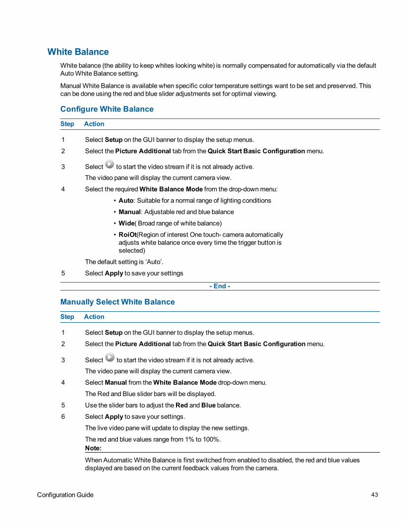
White BalanceWhite balance (the ability to keep whites looking white) is normally compensated for automatically via the defaultAuto White Balance setting.
Manual White Balance is available when specific color temperature settings want to be set and preserved. Thiscan be done using the red and blue slider adjustments set for optimal viewing.
Configure White Balance
Step Action
1 Select Setup on the GUI banner to display the setup menus.
2 Select thePicture Additional tab from theQuick Start Basic Configuration menu.
3 Select to start the video stream if it is not already active.
The video pane will display the current camera view.
Configuration Guide 33

4 Select the requiredWhite Balance Mode from the drop-down menu:
• Auto: Suitable for a normal range of lighting conditions
• Manual: Adjustable red and blue balance
• Wide( Broad range of white balance)
• RoiOt (Region of interest One touch- camera automaticallyadjusts white balance once every time the trigger button isselected)
The default setting is ‘Auto’.
5 Select Apply to save your settings
- End -
Manually Select White Balance
Step Action
1 Select Setup on the GUI banner to display the setup menus.
2 Select thePicture Additional tab from theQuick Start Basic Configuration menu.
3 Select to start the video stream if it is not already active.
The video pane will display the current camera view.
4 Select Manual from theWhite Balance Mode drop-down menu.
The Red and Blue slider bars will be displayed.
5 Use the slider bars to adjust theRed andBlue balance.
6 Select Apply to save your settings.
The live video pane will update to display the new settings.
The red and blue values range from 1% to 100%.Note:
When Automatic White Balance is first switched from enabled to disabled, the red and blue valuesdisplayed are based on the current feedback values from the camera.
- End -
Noise ReductionThe camera provides a Noise Reduction option for delivering optimized image quality, especially in extra low-lightconditions.
The 2D Noise Reduction (2DNR) feature delivers clear images without motion blurs in extra low-light conditions.
Enable/Disable 2DNR
Step Action
1 Select Setup on the GUI banner to display the setup menus.
2 Select 2DNR from thePicture Additional menu.
34

3 Select an option from the 2DNR dropdown menu:
• ON
• OFF
4 Select Apply to save your settings.
- End -
Picture Additional Settings on the Pro Fisheye cameraRefer to Figure 3.6 when configuring Wide Dynamic Range, Day Night Mode, Picture Adjustment, White Balanceand Noise Reduction settings for the Pro Fisheye camera.
Figure 3-6 Picture Additional settings on Pro Fisheye camera
Configuration Guide 35

Wide Dynamic RangeWDR is a feature that allows viewing of high contrast scenes that include both bright and low light areas in thesame field of view (FOV).
The WDR field allows you to choose between favouring an underexposed or overexposed image. By disabling theWDR the image is underexposed; this provides more detail in areas of brightness, but less detail in areas ofdarkness. On the other hand, enabling WDR overexposes the image which provides more detail in the dark areasbut less detail in the bright areas.
A typical use for this feature would be viewing a scene with both indoor and outdoor lighting conditionssimultaneously, such as a warehouse area with an open bay door.
Configure Wide Dynamic Range (WDR) Settings
Step Action
1 Select Setup on the GUI banner to display the setup menus.
2 Select thePicture Additional tab from theQuick Start Basic Configuration menu.
3 Select one of the following options from theWDR dropdown menu
• Low
• Med
• High
• Off
4 Select Apply to carry out the change.
5 The default WDR setting is 'Off'.
- End -
Day Night ModeThe camera provides a black-and-white (B/W) mode to improve camera performance when the light level fallsbelow certain thresholds. This allows clear images to be obtained under low-light conditions. There are fiveDay/Night settings: Auto High, Auto Mid, Auto Low,Forced Black and White and Forced Color.
Configuring Day Night Mode
Step Action
1 Select Setup on the GUI banner to display the setup menus.
2 Select thePicture Additional tab from theQuick Start Basic Configuration menu.
3 Select aDay Night Mode setting from the drop-down menu:
• Auto High
• Auto Mid
• Auto Low
• Forced B &W( night time)
• Forced Color (day time)
• Manual (provides 6 selectable levels of transition between night to day and day to night set-tings)
36

4 Select Apply to save your settings
The default setting is ‘Auto Mid' mode.
- End -
IR Illuminator ControlWhen enabled the IR illuminator Control feature allow the camera to pick up important details from a distanceeven in extremely low light environments.
Enable/Disable IR Illuminator Control
Step Action
1 Select Setup on the GUI banner to display the setup menus.
2 Select thePicture Additional tab from theQuick Start Basic Configuration menu.
3 Enable or disable IR Illuminator Control by checking or unchecking the IR Illuminator Controlcheckbox.
• Check the checkbox to enable IR Illuminator Control
• Uncheck the checkbox to disable IR Illuminator Control.
4 Select Apply to save your settings.
- End -
Picture AdjustmentAdjust brightness, sharpness, contrast, saturation and hue of the image displayed on the video pane.
Adjust Brightness, Sharpness, Contrast, Saturation and Hue
Step Action
1 Select Setup on the GUI banner to display the setup menus.
2 Select thePicture Additional tab from theQuick Start Basic Configuration menu.
3 Select to start the video stream if it is not already active.
The video pane will display the current camera view.
4 Use the slider bars to adjust:
• Brightness
• Sharpness
• Contrast
• Saturation (color level)
• Hue
5 Select Apply to save changes .
The live video pane will update to display the values you have selected.
The values range from 0% to 100%.
Configuration Guide 37

The default values are 50% for brightness, 18% for sharpness, 25% for contrast, 25%for saturation and50% for hue.
The live video pane will update to display the values you have selected.
- End -
Restore Picture Adjustment Defaults
Step Action
1 Select Setup on the GUI banner to display the setup menus.
2 Select thePicture Additional tab from theQuick Start Basic Configuration menu.
3 Select Defaults to restore picture settings to the factory defaults.
- End -
White BalanceWhite balance (the ability to keep whites looking white) is normally compensated for automatically via the defaultAuto White Balance setting.
Manual White Balance is available when specific color temperature settings want to be set and preserved. Thiscan be done using the red and blue slider adjustments set for optimal viewing.
Configure White Balance
Step Action
1 Select Setup on the GUI banner to display the setup menus.
2 Select thePicture Additional tab from theQuick Start Basic Configuration menu.
3 Select to start the video stream if it is not already active.
The video pane will display the current camera view.
4 Select the requiredWhite Balance Mode from the drop-down menu:
5
• Auto: Suitable for a normal range of lighting condition
• Indoor (Best for indoor settings)
• Outdoor (Best for outdoor settings)
6 Select Apply to save your settings
- End -
Noise ReductionThe camera provides multiple Noise Reduction options for delivering optimized image quality, especially in extralow-light conditions.
The 3D Noise Reduction (3DNR) feature delivers optimized image quality, especiallly in extra low-lightconditions.
38

The 2D Noise Reduction (2DNR) feature delivers clear images without motion blurs in extra low-light conditions.
The Color Noise Reduction (ColorNR) feature eliminates color noise when the camera is in color mode in a darkenvironment.
Configure 3DNR settings
Step Action
1 Select Setup on the GUI banner to display the setup menus.
2 Select 3DNR from thePicture Additional menu.
3 Select an option from the 3DNR dropdown menu:
• OFF
• 3DNR High
• 3DNR Mid
• 3DNR Low
4 Select Apply to save your settings.
- End -
Enable/Disable 2DNR
Step Action
1 Select Setup on the GUI banner to display the setup menus.
2 Select 2DNR from thePicture Additional menu.
3 Select an option from the 2DNR dropdown menu:
• ON
• OFF
4 Select Apply to save your settings.
- End -
Configure ColorNR settings
Step Action
1 Select Setup on the GUI banner to display the setup menus.
2 Select Picture Additional from theQuick Start Basic Configuration menu.
3 Select an option from theColorNR dropdown menu:
• Off color
• Low color
• Mid color
• High color
4 Select Apply to save your settings.
- End -
Configuration Guide 39

Picture Additional Settings on the FlexZ cameraRefer to Figure 3.7 when configuring Wide Dynamic Range, Day Night Mode, IR Illuminator Control, Picture
Adjustment, White Balance and Noise Reduction settings for the FlexZ camera.
Figure 3-7 Picture Additional settings on FlexZ camera
True Wide Dynamic Range (TrueWDR)TrueWDR can be used to optimize camera image in environments where there is too much or too little light. WhenTrueWDR is enabled, the camera takes two or more images at different shutter speeds to expose the imageswhich would otherwise be saturated or empty . It then combines the images, providing an image that can showboth the dark and bright areas.
40

Enable/Disable TrueWDR Settings
Step Action
1 Select Setup on the GUI banner to display the setup menus.
2 Select thePicture Additional tab from theQuick Start Basic Configuration menu.
3 Select theOn option from the dropdown TrueWDR menu to enable TrueWDR.
4 Select theOFF option from the dropdown TrueWDR menu to disable TrueWDR.
5 Select Apply to carry out the change.
6 The default TrueWDR setting is 'Off'.
- End -
Day Night ModeThe camera provides a black-and-white (B/W) mode to improve camera performance when the light level fallsbelow certain thresholds. This allows clear images to be obtained under low-light conditions. There are sixDay/Night settings: Auto High, Auto Mid, Auto Low,Forced Black and White, Forced Color, and Manual.
Configuring Day Night Mode
Step Action
1 Select Setup on the GUI banner to display the setup menus.
2 Select thePicture Additional tab from theQuick StartBasic Configuration menu.
3 Select aDay Night Mode setting from the drop-down menu:
• Auto High
• Auto Mid
• Auto Low
• Forced B &W( night time)
• Forced Color (day time)
• Manual (provides 6 selectable levels of transition between night to day and day to night set-tings)
4 Select Apply to save your settings
The default setting is ‘Auto Mid' mode.
- End -
IR Illuminator ControlWhen enabled the IR illuminator Control feature allow the camera to pick up important details from a distanceeven in extremely low light environments.
Enable/Disable IR Illuminator Control
Step Action
1 Select Setup on the GUI banner to display the setup menus.
2 Select thePicture Additional tab from theQuick Start Basic Configuration menu.
Configuration Guide 41

3 Enable or disable IR Illuminator Control by checking or unchecking the IR Illuminator Controlcheckbox.
• Check the checkbox to enable IR Illuminator Control
• Uncheck the checkbox to disable IR Illuminator Control.
4 Select Apply to save your settings
- End -
Picture AdjustmentAdjust brightness, sharpness, contrast, saturation and hue of the image displayed on the video pane.
Adjust Brightness, Sharpness, Saturation and Hue
Step Action
1 Select Setup on the GUI banner to display the setup menus.
2 Select thePicture Additional tab from theQuick Start Basic Configuration menu.
3 Select to start the video stream if it is not already active.
The video pane will display the current camera view.
4 Use the slider bars to adjust:
• Brightness
• Sharpness
• Contrast
• Saturation (color level)
• Hue
5 Select Apply to save changes .
The live video pane will update to display the values you have selected.
The values range from 0% to 100%.
The default values are: 50% for brightness, 18% for sharpness, 25% for contrast, 25% for saturation, and50% for hue.
- End -
Restore Picture Adjustment Defaults
Step Action
1 Select Setup on the GUI banner to display the setup menus.
2 Select thePicture Additional tab from theQuick Start Basic Configuration menu.
3 Select Defaults to restore picture settings to the factory defaults.
- End -
42
White BalanceWhite balance (the ability to keep whites looking white) is normally compensated for automatically via the defaultAuto White Balance setting.
Manual White Balance is available when specific color temperature settings want to be set and preserved. Thiscan be done using the red and blue slider adjustments set for optimal viewing.
Configure White Balance
Step Action
1 Select Setup on the GUI banner to display the setup menus.
2 Select thePicture Additional tab from theQuick Start Basic Configuration menu.
3 Select to start the video stream if it is not already active.
The video pane will display the current camera view.
4 Select the requiredWhite Balance Mode from the drop-down menu:
• Auto: Suitable for a normal range of lighting conditions
• Manual: Adjustable red and blue balance
• Wide( Broad range of white balance)
• RoiOt(Region of interest One touch- camera automaticallyadjusts white balance once every time the trigger button isselected)
The default setting is ‘Auto’.
5 Select Apply to save your settings
- End -
Manually Select White Balance
Step Action
1 Select Setup on the GUI banner to display the setup menus.
2 Select thePicture Additional tab from theQuick Start Basic Configuration menu.
3 Select to start the video stream if it is not already active.
The video pane will display the current camera view.
4 Select Manual from theWhite Balance Mode drop-down menu.
The Red and Blue slider bars will be displayed.
5 Use the slider bars to adjust theRed andBlue balance.
6 Select Apply to save your settings.
The live video pane will update to display the new settings.
The red and blue values range from 1% to 100%.Note:
When Automatic White Balance is first switched from enabled to disabled, the red and blue valuesdisplayed are based on the current feedback values from the camera.
Configuration Guide 43

Noise ReductionThe camera provides multiple Noise Reduction options for delivering optimized image quality, especially in extralow-light conditions.
The 3D Noise Reduction (3DNR) feature delivers optimized image quality, especiallly in extra low-lightconditions.
The 2D Noise Reduction (2DNR) feature delivers clear images without motion blurs in extra low-light conditions.
The Color Noise Reduction (ColorNR) feature eliminates color noise when the camera is in color mode in a darkenvironment.
Configure 3DNR settings
Step Action
1 Select Setup on the GUI banner to display the setup menus.
2 Select thePicture Additional tab from theQuick Start Basic Configuration menu.
3 Select to start the video stream if it is not already active.
The video pane will display the current camera view.
4 Select an option from the 3DNR dropdown menu:
• OFF
• 3DNR High
• 3DNR Mid
• 3DNR Low
5 Select Apply to save your settings.
- End -
Enable/Disable 2DNR
Step Action
1 Select Setup on the GUI banner to display the setup menus.
2 Select thePicture Additional tab from theQuick Start Basic Configuration menu.
3 Select to start the video stream if it is not already active.
The video pane will display the current camera view.
4 Select an option from the 2DNR dropdown menu:
• ON
• OFF
5 Select Apply to save your settings.
- End -
44

Configure ColorNR settings
Step Action
1 Select Setup on the GUI banner to display the setup menus.
2 Select Picture Additional from theQuick Start Basic Configuration menu.
3 Select an option from theColorNR dropdown menu:
• Off color
• Low color
• Mid color
• High color
4 Select Apply to save your settings.
- End -
Lens CalibrationThe lens calibration process can be used to recover focus and zoom after motor stalling has occurred. Motor stepstalling is rare but can occur during shipping or through mishandling of the camera. You can run a Focus & ZoomCalibration from the Lens Calibration tab.Note:
The Lens Calibration tab is only available on the FlexZ camera.
Run a Focus and Zoom Calibration
Step Action
1 Select Setup on the GUI banner to display the setup menus.
2 Select Picture Settings from theVideo menu.
3 Select the Lens Calibration tab.
4 Select Run.
The Focus & Zoom Calibration progress bar is displayed.
5 Remain on the page until the process is complete.
During the calibration process the user must not move the camera or perform any action on the camera.
The calibration process takes approximately 10 seconds to complete.
- End -
Configuration Guide 45

Date/Time/OSDChange the camera name, date and time and enable OSD.Note:
Date and Time can also be configured in theSystem menu. Refer to Date/Time on Page 129.
Camera NameThe camera name will be displayed on the GUI banner and the on-screen display for the camera. This name willalso be displayed when using Illustra Connect or ONVIF.
Change the Camera Name
Step Action
1 Select Setup on the GUI banner.
2 Select theDate/Time/OSD tab in theQuick Start Basic Configuration menu.
3 Enter the name of the camera in theCamera Friendly Name text box.
- End -
Date TimeSet the date and time on the camera.
Configuring the Date and Time
Step Action
1 Select Setup on the GUI banner to display the setup menus.
2 Select Date/Time/OSD from theQuick Start Basic Configuration menu.
3 Select the Time 24-hour check box to enable the 24-hour clock.
Or
Deselect the Time 24-hour check box to enable the 12-hour clock.
The default setting is ‘24-hour’.
4 Select theDate Display Format from the drop-down menu:
• DD/MM/YYYY• MM/DD/YYYY• YYYY/MM/DD
The default setting is ‘YYYY/MM/DD’.
5 Select the Time Zone from the drop-down menu.
The default setting is ‘(GMT-05:00) Eastern Time (US & Canada)'
6 Select theSet Time setting by selecting a radio button:
46

• Manually• via NTP
The default setting is ‘Manually’.
7 If you select 'Manually' in step 6:
a Select the Date (DD/MM/YYYY) using the drop-down menus.
b Select the Time (HH:MM:SS) using the drop-down menus.
8 If you select 'via NTP' in step 6:
• Enter theNTP Server Name in the text box.
The default is 'pool.ntp.org
- End -
Configuration Guide 47

PTZ Settings MenuWhen the video menu is selected, Figure 4-1 PTZ Settings Menu will be displayed:
Figure 4-1 PTZ Settings Menu
The PTZ Settings Menu provides access to the following camera settings and functions:
• PTZ Parameters
• Preset
• Patterns
• Scans
• Sequences
• Home
Note:
The FlexZ camera does not feature a PTZ Settings Menu
8200-1307-01 C0

PTZ ParametersPTZ Parameters allows you to adjust the Automatic Flip featureNote:
PTZ Parameters only apply to specific Fisheye image sources.
Automatic FlipUse the automatic (proportional) “flip” feature when you need to track someone who walks directly under thecamera and continues on the other side. You start the flip by moving the tilt control to its lower limit and holding fora brief period. When the flip engages, the camera automatically rotates 180°. You may then continue to track theperson as long as the tilt control stays in its lower limit. Once the tilt control is released, the camera resumesnormal operation.
Note:
The Automatic Flip feature is not available on the Pro Fisheye camera.
Enable/Disable Automatic Flip
Step Action
1 Select Setup on the GUI banner to display the setup menus.
2 Select PTZ Parameters from thePTZ Settingsmenu.
Select the PTZ Parameters tab.
3 Select theAutomatic Flip check box to enable automatic flip.
OR
Deselect theAutomatic Flip check box to disable automatic flip.
The default setting is ‘Enabled’.
- End -
PresetA Preset is a pre-positioned camera scene that you program using the pan, tilt and zoom options. Up to 50 presetscan be programmed on the camera.Note:
• When using the Pro Fisheye camera note that the selected stream must use an Active Image source.
• On Pro Fisheye camera, when using image sources containing multiple active images, you will need toselect the pane on which to save or launch the preset.
49

Adding a new PresetCreate a new preset position on the camera.
Add a Preset
Step Action
1 Select Setup on the GUI banner to display the setup menus.
2 Select Presets from thePTZ settingsmenu.
The Preset tab displays.
3 Select to start the video stream if it is not already active.
The video pane will display the current camera view.Note:
On the Fisheye camera, you must select the pane on which to launch the preset. Select the pane byclicking on one of the available pane icons.
4 Adjust the camera view as required.
• Pan, Tilt and Zoom.• Focus and Iris points (PTZ only)
Refer to Introduction on Page 6 to make the necessary adjustments.
5 In a numbered slot on the preset table, select to add the new preset.
6 Enter the preset name in thePreset Name text box.
7 Select Add to save the preset.
OR
Select Cancel.
- End -
Viewing a PresetView an existing preset position.
View a Preset
Step Action
1 Select Setup on the GUI banner to display the setup menus.
2 Select Preset from thePTZ settingsmenu.
The Preset tab displays.
3 Select to start the video stream if it is not already active.
Configuration Guide 50

The video pane will display the current camera view.Note:
On the Pro Fisheye camera, you must select the pane on which to launch the preset. Select the pane byclicking on one of the available pane icons.
4 Select to activate the corresponding preset.
The video pane will update to display the selected preset. The preset will display until interrupted by acamera command, pattern or scan.
- End -
Editing a PresetEdit an existing preset position.
Edit an existing Preset
Step Action
1 Select Setup on the GUI banner to display the setup menus.
2 Select Preset from thePTZ settingsmenu.
The Preset tab displays.
3 Select to start the video stream if it is not already active.
The video pane will display the current camera view.Note:
On the Pro Fisheye camera, you must select the pane on which to launch the preset. Select the pane byclicking on one of the available pane icons.
4 Select to activate the corresponding preset.
The video pane will update to display the selected preset.
5 Select to edit the corresponding preset.
6 Edit the preset name in thePreset Name text box if required.
7 Adjust the camera view as required.
• Pan, Tilt and Zoom.• Focus and Iris point (PTZ only).
8 Select Add to save the updated preset.
You will be prompted to confirm the update.
9 Select OK to save the changes.
OR
Select Cancel.
51

Deleting a PresetDelete an existing preset position from the camera.
Delete a Preset
Step Action
1 Select Setup on the GUI banner to display the setup menus.
2 Select Preset from thePTZ menu.
The Preset tab displays.
3 Select to delete the corresponding preset.
You will be prompted to confirm the deletion.
Note:
You cannot delete a preset while it is associated with another camera function. To remove the preset,refer to the associated camera function.
4 Select OK to confirm the deletion.
OR
Select Cancel.
- End -
PatternsA pattern is a series of pan, tilt and zoom movements which can be saved to the camera. A maximum of 9 userprogrammable patterns can be programmed for the camera. A pattern can be configured to record up to 4 minutesof actions.
Adding a PatternCreate a new pattern.Note:
A 15 minute time-out period is implemented when adding a pattern. If no command is received within the time-outperiod, the Add a Pattern procedure will automatically terminate.
Add a Pattern
Step Action
1 Select Setup on the GUI banner to display the setup menus.
2 Select Patterns from thePTZ menu.
Configuration Guide 52

The video pane will display the current camera view.Note:
On the Pro Fisheye camera, you must select the pane on which to launch the pattern. Select the pane byclicking on one of the available pane icons.
3 Enter thePattern Name.
4 Select Start.The Record page will update with anAdd andCancel button.
5 Adjust the camera view as required.
• Pan, Tilt and Zoom.
6 Select Add to save the pattern.
The pattern name is entered in the table on the Patterns tab.
Or
Select Cancel.
- End -
Running a PatternActivate an existing pattern.
Run a Pattern
Step Action
1 Select Setup on the GUI banner to display the setup menus.
2 Select Patterns from thePTZ menu.
The Patterns tab displays.
Select to start the video stream if it is not already active.
The video pane will display the current camera view.Note:
On the Pro Fisheye camera, you must select the pane on which to launch the pattern. Select the pane byclicking on one of the available pane icons.
3 Select to activate the corresponding pattern.
4 The video pane will update to display the selected pattern.The pattern will run continuously untilinterrupted by a camera command, pattern, scan, or alarm.
- End -
Deleting a PatternDelete an existing pattern.
53

Delete a Pattern
Step Action
1 Select Setup on the GUI banner to display the setup menus.
2 Select Patterns from thePTZ settingsmenu.
The Patterns tab displays.
3 Select to delete the corresponding pattern.
You will be prompted to confirm the deletion.
Note:
You cannot delete a pattern while it is associated with another camera function. To remove the pattern,refer to the associated camera function.
4 Select OK to confirm the deletion.
OR
Select Cancel.
- End -
Repeating a PatternUse this procedure to have a pattern repeat until interrupted by a camera command.
Enable/Disable Repeat a Pattern
Step Action
1 Select Setup on the GUI banner to display the setup menus.
2 Select Patterns from thePTZ settingsmenu.
3 Select theRepeat tab.
The Repeat tab displays.
4 Select theRepeat Pattern check box to allow the selected pattern to repeat continuously.
OR
Deselect theRepeat Pattern check box to allow the selected pattern to run only once.
The default setting is ‘Enabled’.
- End -
ScansA scan allows you to program left and right scan limits to automate surveillance activities. Once these scan limitsare programmed, you can choose to run a smooth scan, stepped scan, or random scan. When active, the scanrepeats until interrupted by a camera command, preset, pattern or alarm.
Configuration Guide 54

Note:
When using the Pro Fisheye camera note the following:
• The selected stream must use an Active Image Source to use the scans function.
• Patterns, Sequences and Scans can only be run on one Active Image source at a time. Other ActiveImage sources configured on the camera can utilize vPTZ if required.
Setting Scan LimitsSet left and right scan limits on the camera.
Set Scan Limits
Step Action
1 Select Setup on the GUI banner to display the setup menus.
2 Select Scans from thePTZ settingsmenu.
The Scans tab displays.
3 Select to start the video stream if it is not already active.
The video pane will display the current camera view.Note:
On the Pro Fisheye camera, you must select the pane on which to launch the scan. Select the pane byclicking on one of the available pane icons.
4 Adjust the camera view as required to locate the left scan limit.
5 Select Set Left to set the displayed position as the left limit.
This action sets the tilt and zoom in the position.
6 Adjust the camera view as required to locate the right scan limit.
7 Select Set Right to set the displayed position as the right limit.
The scan limits have been set and the selected scan will now run within the scan limits set.
- End -
Set Scan Limits to Default SettingsReturn the camera to the default scan settings.
Set Scan Limits to Default Settings
Step Action
1 Select Setup on the GUI banner to display the setup menus.
2 Select Scans from thePTZ settingsmenu.
3 Select the Scans tab.
55

The Scans tab displays.
4 Select Defaults.
The scan limits will default to Left: 0 and Right: 359.
- End -
Activating a ScanActivate a scan on the camera, this will run using the scan limits saved in Setting Scan Limits.Note:
Setting left scan limit will also determine the tilt at which the scan will run.
Activate a Scan
Step Action
1 Select Setup on the GUI banner to display the setup menus.
2 Select Scans from thePTZ settingsmenu.
The Scans tab displays.
3 Select to start the video stream if it is not already active.
The video pane will display the current camera view.Note:
On the Pro Fisheye camera, you must select the pane on which to launch the scan. Select the pane byclicking on one of the available pane icons.
(Before activating a scan, refer to Set Scan Limits to Default Settings on Page 55.)
4 Select to activate the corresponding scan.
• Smooth - slowly pans between the left and right scan limits, starting at the left scan limit.When the right scan limit is reached, the scan reverses
• Stepped - pans slowly, pausing briefly every 10° between the left and right scan limits. Oncethe right scan limit is reached, the scan reverses.
• Random - pans randomly between the left and right scan limits. For example, the scan maystart at 10°, then pan right 40° and pause, pan right 20° and pause, pan left 30° and pause, andpan right until it reaches the right scan limit.
5 The video pane will update to display the selected scan.
6 The scan will run continuously until interrupted by a camera command, pattern, preset, or alarm.
- End -
Configuration Guide 56
SequencesA Sequence is a sequential display of multiple camera Presets. Sequences provide a methodical and effectiveway to monitor multiple areas of interest by switching to different Presets automatically.
Sequences are created by identifying Preset views to include in the Sequence and specifying a dwell time thatcontrols how long each Preset remains on-screen before switching to another Preset.
Up to 8 Sequences can be created, each with steps (Presets).Up to 64 presets may be included in a Sequence.Note:
When adding or configuring a sequence on the Pro Fisheye camera, you will need to select the pane on which tosave or launch the preset.
Adding a SequenceCreate a new sequence on the camera using defined presets.
Add a Sequence
Step Action
1 Select Setup on the GUI banner to display the setup menus.
2 Select Sequences from thePTZ settingsmenu.
3 Select theAdd Sequence tab.
4 Enter theSequence Name.
5 Select a preset from thePreset Name drop-down menu.
6 Enter a dwell time in seconds in theDwell Time (sec) text box.
The settings are 5-500.
7 Select Add.
The preset is now listed as part of the sequence.
8 Repeat steps 5 to 7 to add further presets to the sequence.Note:
Up to 8 presets can be added to a sequence.
9 Select Apply to save the sequence.
- End -
57

Activating a SequenceActivate a selected sequence.
Activate a Sequence
Step Action
1 Select Setup on the GUI banner to display the setup menus.
2 Select Sequences from thePTZ settingsmenu.
The Sequences tab displays.
3 Select to start the video stream if it is not already active.
The video pane will display the current camera view.
4 Select to activate the corresponding sequence.
The video pane will update to display the selected sequence.The sequence will run continuously untilinterrupted by a camera command, pattern, preset, scan or alarm.
- End -
Editing a SequenceEdit an existing sequence.
Edit a Sequence
Step Action
1 Select Setup on the GUI banner to display the setup menus.
2 Select Sequences from thePTZ settingsmenu.
The Sequences tab displays.
3 Select to edit the corresponding sequence.
The sequence will open in the Edit Sequence tab.
4 Edit the sequence name in theSequence Name text box if required.
5 Select to edit the corresponding preset. The following can be edited:
• Preset Name: To add a new preset to the sequence, move to the next available free slot andselect a preset from thePreset Name drop-down menu.
• Dwell time
6 If required, select to remove the corresponding preset from the sequence.
7 Select Add to save the changes
OR
Select Cancel.
Configuration Guide 58

8 Select Apply to save the changes.
- End -
Deleting a SequenceDelete an existing sequence.
Delete a Sequence
Step Action
1 Select Setup on the GUI banner to display the setup menus.
2 Select Sequences from thePTZ settingsmenu.
The Sequences tab displays.
3 Select to delete the corresponding sequence.
You will be prompted to confirm the deletion.
4 Select OK to delete the sequence.
Or Select Cancel.
- End -
HomeIt is possible to set a home position for the camera. Once enabled, the home position will be invoked automaticallyafter a specified amount of minutes that the camera has been left static.. It also means that whichever homeposition is set will be the default for the camera. A preset, scan, pattern, or sequence may be set as the homeposition of the camera. Alternatively the none option may be selected .Note:
The Home menu item is not available on the Pro Fisheye camera
Setting a Home PositionSet a home position for the camera
Delete a Sequence
Step Action
1 Select Setup on the GUI banner to display the setup menus.
2 Select Home from thePTZ Settingsmenu.
TheHome tab displays.
3 From theHome Position Type dropdown menu select one of the following options:
59

• Preset• Scan• Pattern• Sequence• None
If you have selected preset, scan, pattern or sequence you will have the option to select a particularReturn to home time from the PTZ parameters you have set up.
- End -
Configuration Guide 60

Video MenuWhen the video menu is selected, Figure 5-1 Video Menu will be displayed.
Figure 5-1 Video Menu
The Video Menu provides access to the following camera settings and functions:
• Streams
• Camera (in Pro Fisheye camera only)
• Picture Settings
• Date/Time/OSD
• Privacy Zones
8200-1307-01 C0

StreamsThe camera allows the configuration of up to three video streams. These streams can be configured via the WebGUI, as detailed here.
Integration with American Dynamics Network Video RecordersStreams can be configured via the Web GUI, as detailed here or via the Network Video Recorder interface.Changes made to the streams via either method will be applied and the video will be displayed according to theconfiguration
Opening the Web GUI live view while the Network Video Recorder is recording video will allow the stream to beshared and will minimize the impact on camera resources.
Integration with other Illustra API ClientsStreams can be configured via the Web GUI, as detailed here, or via the Illustra API interface. Changes made tothe streams via either method will be applied and the video will be displayed according to the configuration.
Opening the Web GUI live video will allow the stream to be shared with the Illustra API and will minimize theimpact on camera resources.
Configuring the Video Stream SettingsAdjust the settings for each video stream.
Configure the Video Stream settings
Step Action
1 Select Setup on the GUI banner to display the setup menus.
2 Select theVideo tab and choose between the stream 1,2, 3 tabs.
The selected tab displays.Note:
When using the Pro Fisheye camera:
• there will be a choice of image sources available to be selected for stream 1.
• the image source choices that are available vary according to camera dewarp mode andmount option settings.
• the image selection in Stream 1 is replicated in Streams 2 and 3.
3 Select the requiredCodec by selecting the radio buttons:
• H264• MJPEG
4 Select the requiredResolution from the drop-down menu.The resolutions available will depend on the Image Source selected:
5 Use the slider bar to select the Frame Rate (Frames Per Second).
62

6 Use the slider bar to select theGroup of Pictures (GOP) length.
7 If MJPEG has been selected, MJPEG Quality will be enabled. Use the slider bar to select theMJPEGQuality.
OR
8 If H264 has been selected, Rate Control will be enabled. Select the requiredRate Control by selectingthe radio buttons:
• VBR (Variable Bit Rate)• CBR (Constant Bit Rate)• CVBR (Constrained Variable Bit Rate)
The default setting is ‘VBR’.
a If VBR has been selected, VBR Quality will be enabled. Select the requiredVBR Quality from thedrop-down menu.
• Highest
• High
• Medium
• Low
• Lowest
The default setting is ‘High’.
OR
b If CBR has been selected, CBR Bit Rate will be enabled. Use the slider bar to select theCBR BitRate
OR
c If CVBR has been selected, CVBR Quality and Bitrate will be enabled. Select the required CVBRQuality from the dropdown menu.
• Highest
• High
• Medium
• Low
• Lowest
The default setting is 'High'.
AND
Use the slider bar to select theCVBR Bit Rate.
- End -
CameraThe camera menu contains camera viewing options
Configuration Guide 63

Note:
Camera menu options are only available on the Pro Fisheye camera.
Mounting ViewThe camera view setting can be switched from wall mounted or ceiling mounted according to how you havemounted the camera.
Enable Camera view
Step Action
1 Select Setup on the GUI banner to display the setup menus.
2 Select Camera from theVideo menu.
TheMounting tab displays.
3 Select theCeiling checkbox to enable the ceiling mounted view
OR
Select theWall checkbox to enable the wall mounted view.
- End -
DewarpThe dewarping feature clarifies image distortion, enabling the Pro Fisheye camera to have the same range of viewas a PTZ camera. The user may choose to have a Fisheye stream or a stream that has already been dewarpedstream directly to the camera.
Enable Dewarping
Step Action
1 Select Setup on the GUI banner to display the setup menus.
2 Select Camera from theVideo menu.
The Camera tab displays.
3 Select theEdge checkbox to enable Edge dewarping view.
The camera provides a fisheye or a choice of dewarped streams, depending on the user's requirements.
OR
Select theClient checkbox to enable the Client dewarping view.
The camera will provide only a Fisheye stream.Note:
The dewarping feature is only available on the Pro Fisheye camera.
- End -
64

Picture Basic TabOrientation, zoom and exposure settings are configured from the Picture Basics tab.
Picture Basic Settings on the Flex PTZ CameraThe Flex PTZ camera orientation and exposure settings may be configured to optimize visual quality.
Refer to Figure 5.2 when configuring the camera orientation and exposure settings on the Flex PTZ camera.
Figure 5-2 Picture Basic settings on Flex PTZ camera
Picture RotationThe Picture Rotation of the camera may be set to normal video or at 180 degrees.
Set Picture Rotation
Step Action
1 Select Setup on the GUI banner to display the setup menus.
2 Select Picture Settings from theVideo menu.
Configuration Guide 65
3 Select thePicture Basic tab.
4 Select theOrientation check box to either:
• Normal video• 180 degree rotate
The orientation of the camera updates to the orientation you have selected on the live feed.
5 Select Apply to save your changes.
- End -
.
Max GainThe Max Gain setting increases or reduces picture noise.The trade-off between picture level (brightness) andnoise may be adjusted by enabling or disabling the Max Gain feature. Enabling the Max Gain settings may resultin a darker picture, but with less noise. Disabling the Max Gain settings may result in a brighter picture, but withmore noise.
Full Auto ModeIn this mode, the camera's shutter speed, iris and Auto Gain Control (AGC) circuits work together automatically tomaintain a consistent video output level.
Max Gain Setting Options: Full Auto, Shutter Priority, P-Iris, Iris Priority, andManual Mode
When Shutter Priority or Iris Priority are enabled, the camera automatically compensates for scene changes thataffect light levels .
In Shutter Priority Mode the iris is adjusted first to control the exposure. Then Gain can be adjusted.
In P-Iris mode the minimum iris opening is limited to minimize defraction.
In Iris Priority Mode the iris setting is fixed. The shutter speed is adjusted first to control the exposure. Then Gainis used when needed.
If Manual Mode is selected, users can adjust the shutter speed, Iris, and Gain settings manually.
Configure Exposure Settings
Step Action
1 Select Setup on the GUI banner to display the setup menus.
2 Select Picture Settings from theVideo menu.
3 Select thePicture Basic tab.
4 Select to start the video stream if it is not already active.
5 Select Auto Mode check box to enable Auto Mode or deselect Auto Mode check box to disable AutoMode.
The default setting is disabled.
66

If Auto Mode has been selected in Step 4, Max Gain will be enabled.
6 Max Gain may be increased and decreased by selecting the desired setting from the dropdown menu.
7 The video pane will update to display the new settings.
8 Select Apply to save your changes.
- End -
Shutter PriorityEnable or disable Shutter Priority mode.
Enable/Disable Shutter Priority Mode
Step Action
1 Select Setup on the GUI banner to display the setup menus.
2 Select Picture Settings from theVideo menu.
3 Select thePicture Basic tab.
4 Select theShutter Priority check box to enable Shutter Priority mode.
OR
Deselect theShutter Priority check box to disable Shutter Priority mode.
The default setting is ‘Disabled’.
5 The shutter time is configurable using the dropdown menu.
6 Select Apply to save your changes.
- End -
P-Iris ModeEnable or disable P-Iris mode.
Enable/Disable P-Iris Mode
Step Action
1 Select Setup on the GUI banner to display the setup menus.
2 Select Picture Settings from theVideo menu.
3 Select thePicture Basic tab.
4 Select theP-Iris check box to enable P-Iris mode.
OR
Deselect theP-Iris check box to disable P-Iris mode.
The default setting is ‘Disabled’.
Configuration Guide 67

5 The maximum exposure time is configurable using the dropdown menu.
6 Select Apply to save your changes.
- End -
Iris-PriorityEnable or disable Iris Priority mode.
Enable/Disable Iris Priority Mode
Step Action
1 Select Setup on the GUI banner to display the setup menus.
2 Select Picture Settings from theVideo menu.
3 Select thePicture Basic tab.
4 Select the Iris Priority check box to enable Iris Priority mode.
OR
Deselect the Iris Priority check box to disable Iris Priority mode.
The default setting is ‘Disabled’.
5 The maximum exposure time is configurable using the dropdown menu.
6 Select Apply to save your changes.
- End -
Manual ModeEnable or disable Manual Mode.
Enable/Disable Iris Manual Mode
Step Action
1 Select Setup on the GUI banner to display the setup menus.
2 Select Picture Settings from theVideo menu.
3 Select thePicture Basic tab.
4 Select theManual check box to enable Manual mode.
OR
Deselect theManual check box to disable Manual mode.
The default setting is ‘Disabled’.
5 Select Apply to save your changes.
- End -
68

Configure Manual Mode Settings
Step Action
1 Select Setup on the GUI banner to display the setup menus.
2 Select Picture Settings from theVideo menu.
3 Select thePicture Basic tab.
4 Select theManual check box to enable Manual mode.
5 Adjust the Shutter, Iris and Gain settings by selecting the desired settings from the dropdown menus.
6 Select Apply to save your changes.
- End -
Picture Basic Settings on the Pro Fisheye CameraThe Pro Fisheye camera exposure settings may be configured to optimize visual quality.
Refer to Figure 5.3 when configuring the camera orientation and exposure settings on the Pro Fisheye camera.
Figure 5-3 Picture Basic settings on Pro Fisheye camera
Auto Shutter ModeIn this mode, the camera's shutter speed adjusts automatically to maintain a consistent video output level.
Manual ModeIn this mode the camera's shutter speed can be adjusted manually to attain the desired video output level.
Configuration Guide 69

Auto Shutter ModeEnable or disable Auto Shutter mode.
Manual ModeEnable or disable Manual Mode.
Enable/Disable Auto Shutter Mode
Step Action
1 Select Setup on the GUI banner to display the setup menus.
2 Select Picture Settings from theVideo menu.
3 Select thePicture Basic tab.
4 Select theAuto Shutter check box to enable Auto Shutter mode.
OR
Deselect theAuto Shutter check box to disable Auto Shutter mode.
The default setting is ‘Enabled’.
5 Select Apply to save your settings.
- End -
Configure Auto Shutter Mode Settings
Step Action
1 Select Setup on the GUI banner to display the setup menus.
2 Select Picture Settings from theVideo menu.
3 Select thePicture Basic tab.
4 Select theAuto Shutter check box to enable Auto Shutterl mode.
5 Adjust the Shutter speed by using the dropdwn menu to select the desired minimum shutter speed.
6 Adjust the Max Gain settings using the dropdown menu to select the desired value.
7 Select Apply to save your settings.
- End -
Enable/Disable Manual Mode
Step Action
1 Select Setup on the GUI banner to display the setup menus.
2 Select Picture Settings from theVideo menu.
3 Select thePicture Basic tab.
4 Select theManual check box to enable Manual mode.
OR
Deselect theManual check box to disable Manual mode.
70

The default setting is ‘Disabled’.
5 Select Apply to save your settings.
- End -
Configure Manual Mode Settings
Step Action
1 Select Setup on the GUI banner to display the setup menus.
2 Select Picture Settings from theVideo menu.
3 Select thePicture Basic tab.
4 Select theManual check box to enable Manual mode.
5 Adjust the Shutter speed by using the dropdwn menu to select the desired shutter speed.
6 Adjust the Gain settings using the dropdown menu to select the desired value.
7 Select Apply to save your settings.
- End -
Configuration Guide 71

Picture Basic Settings on the FlexZ CameraThe FlexZ camera orientation, zoom, and exposure settings may be configured to optimize visual quality.
Refer to Figure 5.4 when configuring camera orientation, zoom, and exposure settings for the FlexZ camera.
Figure 5-4 Picture Basic settings on FlexZ camera
Picture RotationThe Picture Rotation of the camera may be set to normal video or at 180 degrees.
Set Picture Rotation
Step Action
1 Select Setup on the GUI banner to display the setup menus.
2 Select thePicture Basic tab from theQuick Start Basic Configuration menu.
3 Select one of the followingOrientation check boxes:
• Normal video
72

• Flip• 180 degree rotate• Mirror video
The orientation of the camera updates to the orientation you have selected on the live feed.
The default setting is 'normal video'.
4 Select Apply to save your changes.
- End -
Focus and Zoom Settings on the FlexZ CameraThe FlexZ camera focus and zoom settings may be configured to optimize focus and zoom quality.
The zoom settings can be configured by using the zoom slider bar to widen or narrow the zoom.
The Auto Focus mode may be set to manual mode or auto mode.
If the Manual option is selected, the zoom may be altered by using the One Touch button to refocus the camera tooptimal focus and zoom.
If the Auto mode is selected, the zoom will refocus automatically to optimise the quality of focus and zoom on theimage.
Widen/Narrow the Camera Zoom Setting
Step Action
1 Select Setup on the GUI banner to display the setup menus.
2 Select Picture Settings from theVideo menu.
3 Select thePicture Basic tab.
4 Widen the zoom setting on the camera by dragging the Zoom slider bar to the left( towardWide).
OR
Narrow the zoom setting on the camera by dragging the slider bar to the right (toward Tele).
The updated zoom setting will display on the live feed.
5 Select Apply to save your settings.
- End -
Select AutoFocus Mode
Step Action
1 Select Setup on the GUI banner to display the setup menus.
2 Select Picture Settings from theVideo menu.
3 Select thePicture Basic tab.
4 Select one of theAF Mode options by checking one of the checkboxes.
The options are:
Configuration Guide 73

• Manual• Auto (for automatic focus adjustments at each zoom level change)
5 Select Apply to save your settings.
- End -
Configure Manual AutoFocus mode
Step Action
1 Select Setup on the GUI banner to display the setup menus.
2 Select Picture Settings from theVideo menu.
3 Select thePicture Basic tab.
4 Select theManual checkbox from the AF Mode options.
5 Select theOne Touch button.
The camera refocuses to the optimal zoom level for the image
OR
Use the plus and minus arrows at either side of theOne touchbutton to manually configure the focus andthe slider bar to adjust zoom settings until the image is at desired zoom/focus point.
6 Select Apply to save your settings.
- End -
Exposure Settings on the FlexZ CameraThe FlexZ camera exposure settings may be configured to optimize visual quality.
P-Iris Priority ModeIn this mode, the camera's iris size can be increased and decreased. The changes can be made manually or userscan select an option where the camera will automatically detect the best size for the environment.
Iris size, gain and shutter speed settings can still be configured manually in this mode.
Manual ModeIn this mode the camera's shutter speed and gain setting can be adjusted manually to attain the desired videooutput level.
Enable P-Iris Priority Mode
Step Action
1 Select Setup on the GUI banner to display the setup menus.
2 Select Picture Settings from theVideo menu.
3 Select thePicture Basic tab.
74

4 Select theP-Iris Priority check box to enable P-Iris Priority mode.
The default setting is ‘Enabled’.
5 Select Apply to save your settings.
- End -
Configure P-Iris Priority Mode Settings
Step Action
1 Select Setup on the GUI banner to display the setup menus.
2 Select Picture Settings from theVideo menu.
3 Select thePicture Basic tab.
4 Select theP-Iris Priorityr check box to enable P-Iris Priority mode.
5 Select the Auto Detect button and the camera automatically detect the best iris size for theenvironment.. In addition, users can manually adjust the iris size by selecting the plus and minus buttonsto adjust the iris size further.
You can click on to reset the iris size. The iris size will reset to its largest size. Adjust he irissize settings until you are happy with the setting.
6 Adjust the shutter speed and gain settings using the dropdown menus.
7 Select Apply to save your settings.
- End -
Enable Manual Mode
Step Action
1 Select Setup on the GUI banner to display the setup menus.
2 Select Picture Settings from theVideo menu.
3 Select thePicture Basic tab.
4 Select theManual check box to enable Manual mode.
The default setting is ‘Disabled’.
5 Select Apply to save your settings.
- End -
Configure Manual Mode Settings
Step Action
1 Select Setup on the GUI banner to display the setup menus.
2 Select Picture Settings from theVideo menu.
3 Select thePicture Basic tab.
4 Select theManual check box to enable Manual mode.
5 Adjust the Shutter speed by using the dropdwn menu to select the desired shutter speed.
Configuration Guide 75
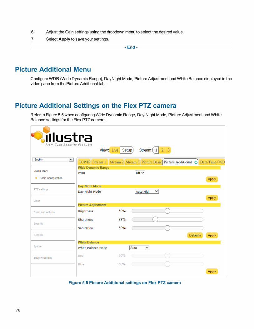
6 Adjust the Gain settings using the dropdown menu to select the desired value.
7 Select Apply to save your settings.
- End -
Picture Additional MenuConfigure WDR (Wide Dynamic Range), DayNight Mode, Picture Adjustment and White Balance displayed in thevideo pane from the Picture Additional tab.
Picture Additional Settings on the Flex PTZ cameraRefer to Figure 5.5 when configuring Wide Dynamic Range, Day Night Mode, Picture Adjustment and WhiteBalance settings for the Flex PTZ camera.
Figure 5-5 Picture Additional settings on Flex PTZ camera
76

Wide Dynamic RangeWDR is a feature that allows viewing of high contrast scenes that include both bright and low light areas in thesame field of view (FOV).
The WDR field allows you to choose between favouring an underexposed or overexposed image. By disabling theWDR the image is underexposed; this provides more detail in areas of brightness, but less detail in areas ofdarkness. On the other hand, enabling WDR overexposes the image which provides more detail in the dark areasbut less detail in the bright areas.
A typical use for this feature would be viewing a scene with both indoor and outdoor lighting conditionssimultaneously, such as a warehouse area with an open bay door.
Enable/Disable Wide Dynamic Range (WDR)
Step Action
1 Select Setup on the GUI banner to display the setup menus.
2 Select Picture Settings from theVideo menu.
3 Select thePicture Additional tab.
4 Select theOn option from theWDR dropdown menu to enable WDR.
5 Select theOff option from theWDR dropdown menu to disable WDR.
6 Select Apply to carry out the change.
7 The default WDR setting is 'Off'.
- End -
Day Night ModeThe camera provides a black-and-white (B/W) mode to improve camera performance when the light level fallsbelow certain thresholds. This allows clear images to be obtained under low-light conditions. There are sixDay/Night settings: Auto High, Auto Mid, Auto Low,Forced Black and White , Forced Color and Manual.
Configuring Day Night Mode
Step Action
1 Select Setup on the GUI banner to display the setup menus.
2 Select Picture Settings from theVideo menu.
3 Select thePicture Additional tab.
4 Select aDay Night Mode setting from the drop-down menu:
• Auto High
• Auto Mid
• Auto Low
• Forced B &W( night time)
• Forced Color (day time)
• Manual (provides 6 selectable levels of transition between night to day and day to night set-tings)
5 Select Apply to save your settings
Configuration Guide 77

The default setting is ‘Auto Mid' mode.
- End -
Picture AdjustmentAdjust brightness, sharpness and saturation of the image displayed on the video pane.
Adjust Brightness, Sharpness, and Saturation
Step Action
1 Select Setup on the GUI banner to display the setup menus.
2 Select Picture Settings from theVideo menu.
3 Select thePicture Additional tab.
4 Select to start the video stream if it is not already active.
The video pane will display the current camera view.
5 Use the slider bars to adjust:
• Brightness
• Sharpness
• Saturation (color level)
6 Select Apply to save changes .
The live video pane will update to display the values you have selected.
The values range from 0% to 100%.
• The default values are: 50% for brightness and saturation,and 33% for sharpness.
- End -
Restore Picture Adjustment Defaults
Step Action
1 Select Setup on the GUI banner to display the setup menus.
2 Select Picture Settings from theVideo menu.
3 Select thePicture Additional tab.
4 Select Defaults to restore picture settings to the factory defaults.
- End -
White BalanceWhite balance (the ability to keep whites looking white) is normally compensated for automatically via the defaultAuto White Balance setting.
Manual White Balance is available when specific color temperature settings want to be set and preserved. Thiscan be done using the red and blue slider adjustments set for optimal viewing.
78

Configure White Balance
Step Action
1 Select Setup on the GUI banner to display the setup menus.
2 Select Picture Settings from theVideo menu.
3 Select thePicture Additional tab.
4 Select to start the video stream if it is not already active.
The video pane will display the current camera view.
5 Select the requiredWhite Balance Mode from the drop-down menu:
• Auto: Suitable for a normal range of lighting conditions
• Manual: Adjustable red and blue balance
• Wide( Broad range of white balance)
• RoiOt(Region of interest One touch- camera automaticallyadjusts white balance once every time the trigger button isselected)
The default setting is ‘Auto’.
6 Select Apply to save your settings
- End -
Manually Select White Balance
Step Action
1 Select Setup on the GUI banner to display the setup menus.
2 Select Picture Settings from theVideo menu.
3 Select thePicture Additional tab.
4 Select to start the video stream if it is not already active.
The video pane will display the current camera view.
5 Select Manual from theWhite Balance Mode drop-down menu.
The Red and Blue slider bars will be displayed.
6 Use the slider bars to adjust theRed andBlue balance.
7 Select Apply to save your settings.
The live video pane will update to display the new settings.
The red and blue values range from 1% to 100%.Note:
When Automatic White Balance is first switched from enabled to disabled, the red and blue valuesdisplayed are based on the current feedback values from the camera.
- End -
Configuration Guide 79
Noise ReductionThe camera provides a Noise Reduction option for delivering optimized image quality, especially in extra low-lightconditions.
The 2D Noise Reduction (2DNR) feature delivers clear images without motion blurs in extra low-light conditions.
Enable/Disable 2DNR
Step Action
1 Select Setup on the GUI banner to display the setup menus.
2 Select 2DNR from thePicture Additional menu.
3 Select an option from the 2DNR dropdown menu:
• ON
• OFF
4 Select Apply to save your settings.
- End -
80

Picture Additional Settings on the Pro Fisheye cameraRefer to Figure 5.6 when configuring Wide Dynamic Range, Day Night Mode, Picture Adjustment, White Balanceand Noise Reduction settings for the Pro Fisheye camera.
Figure 5-6 Picture Additional settings on Pro Fisheye camera
Wide Dynamic RangeWDR is a feature that allows viewing of high contrast scenes that include both bright and low light areas in thesame field of view (FOV).
The WDR field allows you to choose between favouring an underexposed or overexposed image. By disabling theWDR the image is underexposed; this provides more detail in areas of brightness, but less detail in areas ofdarkness. On the other hand, enabling WDR overexposes the image which provides more detail in the dark areasbut less detail in the bright areas.
Configuration Guide 81

A typical use for this feature would be viewing a scene with both indoor and outdoor lighting conditionssimultaneously, such as a warehouse area with an open bay door.
Configure Wide Dynamic Range (WDR) Settings
Step Action
1 Select Setup on the GUI banner to display the setup menus.
2 Select Picture Settings from theVideo menu.
3 Select thePicture Additional tab.
4 Select one of the following options from theWDR dropdown menu
• Low
• Med
• High
• Off
5 Select Apply to carry out the change.
6 The default WDR setting is 'Off'.
- End -
Day Night ModeThe camera provides a black-and-white (B/W) mode to improve camera performance when the light level fallsbelow certain thresholds. This allows clear images to be obtained under low-light conditions. There are fiveDay/Night settings: Auto High, Auto Mid, Auto Low,Forced Black and White and Forced Color.
Configuring Day Night Mode
Step Action
1 Select Setup on the GUI banner to display the setup menus.
2 Select Picture Settings from theVideo menu.
3 Select thePicture Additional tab.
4 Select aDay Night Mode setting from the drop-down menu:
• Auto High
• Auto Mid
• Auto Low
• Forced B &W( night time)
• Forced Color (day time)
• Manual (provides 6 selectable levels of transition between night to day and day to night set-tings)
5 Select Apply to save your settings
The default setting is ‘Auto Mid' mode.
- End -
82

IR Illuminator ControlWhen enabled the IR illuminator Control feature allow the camera to pick up important details from a distanceeven in extremely low light environments.
Enable/Disable IR Illuminator Control
Step Action
1 Select Setup on the GUI banner to display the setup menus.
2 Select Picture Settings from theVideo menu.
3 Select thePicture Additional tab.
4 Enable or disable IR Illuminator Control by checking or unchecking the IR Illuminator Controlcheckbox.
• Check the checkbox to enable IR Illuminator Control
• Uncheck the checkbox to disable IR Illuminator Control.
5 Select Apply to save your settings.
- End -
Picture AdjustmentAdjust brightness, sharpness, contrast, saturation and hue of the image displayed on the video pane.
Adjust Brightness, Sharpness, Contrast, Saturation and Hue
Step Action
1 Select Setup on the GUI banner to display the setup menus.
2 Select Picture Settings from theVideo menu.
3 Select thePicture Additional tab.
4 Select to start the video stream if it is not already active.
The video pane will display the current camera view.
5 Use the slider bars to adjust:
• Brightness
• Sharpness
• Contrast
• Saturation (color level)
• Hue
6 Select Apply to save changes .
The live video pane will update to display the values you have selected.
The values range from 0% to 100%.
The default values are 50% for brightness, 18% for sharpness, 25% for contrast, 25%for saturation and50% for hue.
The live video pane will update to display the values you have selected.
Configuration Guide 83

Restore Picture Adjustment Defaults
Step Action
1 Select Setup on the GUI banner to display the setup menus.
2 Select Picture Settings from theVideo menu.
3 Select thePicture Additional tab.
4 Select Defaults to restore picture settings to the factory defaults.
- End -
White BalanceWhite balance (the ability to keep whites looking white) is normally compensated for automatically via the defaultAuto White Balance setting.
Manual White Balance is available when specific color temperature settings want to be set and preserved. Thiscan be done using the red and blue slider adjustments set for optimal viewing.
Configure White Balance
Step Action
1 Select Setup on the GUI banner to display the setup menus.
2 Select Picture Settings from theVideo menu.
3 Select thePicture Additional tab.
4 Select to start the video stream if it is not already active.
The video pane will display the current camera view.
5 Select the requiredWhite Balance Mode from the drop-down menu:
6
• Auto: Suitable for a normal range of lighting condition
• Indoor (Best for indoor settings)
• Outdoor (Best for outdoor settings)
7 Select Apply to save your settings
- End -
Noise ReductionThe camera provides multiple Noise Reduction options for delivering optimized image quality, especially in extralow-light conditions.
The 3D Noise Reduction (3DNR) feature delivers optimized image quality, especiallly in extra low-lightconditions.
The 2D Noise Reduction (2DNR) feature delivers clear images without motion blurs in extra low-light conditions.
The Color Noise Reduction (ColorNR) feature eliminates color noise when the camera is in color mode in a darkenvironment.
84
Configure 3DNR settings
Step Action
1 Select Setup on the GUI banner to display the setup menus.
2 Select Picture Settings from theVideo menu.
3 Select 3DNR from thePicture Additional menu.
4 Select an option from the 3DNR dropdown menu:
• OFF
• 3DNR High
• 3DNR Mid
• 3DNR Low
5 Select Apply to save your settings.
- End -
Enable/Disable 2DNR
Step Action
1 Select Setup on the GUI banner to display the setup menus.
2 Select Picture Settings from theVideo menu.
3 Select 2DNR from thePicture Additional menu.
4 Select an option from the 2DNR dropdown menu:
• ON
• OFF
5 Select Apply to save your settings.
- End -
Configure ColorNR settings
Step Action
1 Select Setup on the GUI banner to display the setup menus.
1 Select Picture Settings from theVideo menu.
2 Select thePicture Additional tab.
3 Select an option from theColorNR dropdown menu:
• Off color
• Low color
• Mid color
• High color
4 Select Apply to save your settings.
- End -
Configuration Guide 85

Picture Additional Settings on the FlexZ cameraRefer to Figure 5.7 when configuring Wide Dynamic Range, Day Night Mode, IR Illuminator Control, PictureAdjustment, White Balance and Noise Reduction settings for the FlexZ camera.
Figure 5-7 Picture Additional settings on FlexZ camera
True Wide Dynamic Range (TrueWDR)TrueWDR can be used to optimize camera image in environments where there is too much or too little light. WhenTrueWDR is enabled, the camera takes two or more images at different shutter speeds to expose the imageswhich would otherwise be saturated or empty . It then combines the images, providing an image that can showboth the dark and bright areas.
86

Enable/Disable TrueWDR Settings
Step Action
1 Select Setup on the GUI banner to display the setup menus.
2 Select Picture Settings from theVideo menu.
3 Select thePicture Additional tab.
4 Select theOn option from the dropdown TrueWDR menu to enable TrueWDR.
5 Select theOFF option from the dropdown TrueWDR menu to disable TrueWDR.
6 Select Apply to carry out the change.
7 The default TrueWDR setting is 'Off'.
- End -
Day Night ModeThe camera provides a black-and-white (B/W) mode to improve camera performance when the light level fallsbelow certain thresholds. This allows clear images to be obtained under low-light conditions. There are fiveDay/Night settings: Auto High, Auto Mid, Auto Low,Forced Black and White and Forced Color.
Configuring Day Night Mode
Step Action
1 Select Setup on the GUI banner to display the setup menus.
2 Select Picture Settings from theVideo menu.
3 Select thePicture Additional tab.
4 Select aDay Night Mode setting from the drop-down menu:
• Auto High
• Auto Mid
• Auto Low
• Forced B &W( night time)
• Forced Color (day time)
• Manual (provides 6 selectable levels of transition between night to day and day to night set-tings)
5 Select Apply to save your settings
The default setting is ‘Auto Mid' mode.
- End -
IR Illuminator ControlWhen enabled the IR illuminator Control feature allow the camera to pick up important details from a distanceeven in extremely low light environments.
Configuration Guide 87

Enable/Disable IR Illuminator Control
Step Action
1 Select Setup on the GUI banner to display the setup menus.
2 Select Picture Settings from theVideo menu.
3 Select thePicture Additional tab.
4 Enable or disable IR Illuminator Control by checking or unchecking the IR Illuminator Controlcheckbox.
• Check the checkbox to enable IR Illuminator Control
• Uncheck the checkbox to disable IR Illuminator Control.
5 Select Apply to save your settings
- End -
Picture AdjustmentAdjust brightness, sharpness, contrast, saturation and hue of the image displayed on the video pane.
Adjust Brightness, Sharpness, Saturation and Hue
Step Action
1 Select Setup on the GUI banner to display the setup menus.
2 Select Picture Settings from theVideo menu.
3 Select thePicture Additional tab.
4 Select to start the video stream if it is not already active.
The video pane will display the current camera view.
5 Use the slider bars to adjust:
• Brightness
• Sharpness
• Contrast
• Saturation (color level)
• Hue
6 Select Apply to save changes .
The live video pane will update to display the values you have selected.
The values range from 0% to 100%.
The default values are: 50% for brightness, 18% for sharpness, 25% for contrast, 25% for saturation, and50% for hue.
- End -
88

Restore Picture Adjustment Defaults
Step Action
1 Select Setup on the GUI banner to display the setup menus.
2 Select Picture Settings from theVideo menu.
3 Select thePicture Additional tab.
4 Select Defaults to restore picture settings to the factory defaults.
- End -
White BalanceWhite balance (the ability to keep whites looking white) is normally compensated for automatically via the defaultAuto White Balance setting.
Manual White Balance is available when specific color temperature settings want to be set and preserved. Thiscan be done using the red and blue slider adjustments set for optimal viewing.
Configure White Balance
Step Action
1 Select Setup on the GUI banner to display the setup menus.
2 Select Picture Settings from theVideo menu.
3 Select thePicture Additional tab.
4 Select to start the video stream if it is not already active.
The video pane will display the current camera view.
5 Select the requiredWhite Balance Mode from the drop-down menu:
• Auto: Suitable for a normal range of lighting conditions
• Manual: Adjustable red and blue balance
• Wide( Broad range of white balance)
• RoiOt(Region of interest One touch- camera automaticallyadjusts white balance once every time the trigger button isselected)
The default setting is ‘Auto’.
6 Select Apply to save your settings
- End -
Manually Select White Balance
Step Action
1 Select Setup on the GUI banner to display the setup menus.
2 Select Picture Settings from theVideo menu.
3 Select thePicture Additional tab.
Configuration Guide 89

4 Select to start the video stream if it is not already active.
The video pane will display the current camera view.
5 Select Manual from theWhite Balance Mode drop-down menu.
The Red and Blue slider bars will be displayed.
6 Use the slider bars to adjust theRed andBlue balance.
7 Select Apply to save your settings.
The live video pane will update to display the new settings.
The red and blue values range from 1% to 100%.Note:
When Automatic White Balance is first switched from enabled to disabled, the red and blue valuesdisplayed are based on the current feedback values from the camera.
- End -
Noise ReductionThe camera provides multiple Noise Reduction options for delivering optimized image quality, especially in extralow-light conditions.
The 3D Noise Reduction (3DNR) feature delivers optimized image quality, especiallly in extra low-lightconditions.
The 2D Noise Reduction (2DNR) feature delivers clear images without motion blurs in extra low-light conditions.
The Color Noise Reduction (ColorNR) feature eliminates color noise when the camera is in color mode in a darkenvironment.
Configure 3DNR settings
Step Action
1 Select Setup on the GUI banner to display the setup menus.
2 Select Picture Settings from theVideo menu.
3 Select thePicture Additional tab.
4 Select an option from the 3DNR dropdown menu:
• OFF
• 3DNR High
• 3DNR Mid
• 3DNR Low
5 Select Apply to save your settings.
- End -
Enable/Disable 2DNR
Step Action
1 Select Setup on the GUI banner to display the setup menus.
90

2 Select Picture Settings from theVideo menu.
3 Select thePicture Additional tab.
4 Select an option from the 2DNR dropdown menu:
• ON
• OFF
5 Select Apply to save your settings.
- End -
Configure ColorNR settings
Step Action
1 Select Setup on the GUI banner to display the setup menus.
2 Select Picture Settings from theVideo menu.
3 Select thePicture Additional tab.
4 Select an option from theColorNR dropdown menu:
• Off color
• Low color
• Mid color
• High color
5 Select Apply to save your settings.
- End -
Lens CalibrationThe lens calibration process can be used to recover focus and zoom after motor stalling has occurred. Motor stepstalling is rare but can occur during shipping or through mishandling of the camera.
You can run a Focus & Zoom Calibration from the Lens Calibration tab.Note:
The Lens Calibration tab is only available on the FlexZ camera.
Run a Focus and Zoom Calibration
Step Action
1 Select Setup on the GUI banner to display the setup menus.
2 Select Picture Settings from theVideo menu.
3 Select the Lens Calibration tab.
4 Select Run.
The Focus & Zoom Calibration progress bar is displayed.
Configuration Guide 91
5 Remain on the page until the process is complete.
During the calibration process the user must not move the camera or perform any action on the camera.
The calibration process takes approximately 10 seconds to complete.
- End -
Date/Time/OSDChange the camera name and date and time and enable OSD.
Camera NameThe camera name will be displayed on the GUI banner and the on-screen display for the camera. This name willalso be displayed when using Illustra Connect or ONVIF.
Change the Camera Name
Step Action
1 Select Setup on the GUI banner.
2 Select Date/Time/OSD from theVideo menu.
The Date/Time/OSD tab displays.
3 Enter the name of the camera in theCamera Friendly Name text box.
4 Select Apply to save your changes.
- End -
Date TimeSet the date and time on the camera.
Configuring the Date and Time
Step Action
1 Select Setup on the GUI banner to display the setup menus.
2 Select Date/Time/OSD from theVideo menu.
The Date/Time/OSD tab displays.
3 Select the Time 24-hour check box to enable the 24-hour clock.
Or
Deselect the Time 24-hour check box to enable the 12-hour clock.
The default setting is ‘24-hour’.
4 Select theDate Display Format from the drop-down menu:
92
• DD/MM/YYYY• MM/DD/YYYY• YYYY/MM/DD
The default setting is ‘YYYY/MM/DD’.
5 Select the Time Zone from the drop-down menu.
The default setting is ‘(GMT-05:00) Eastern Time (US & Canada)
6 Select theSet Time setting by selecting a radio button:
• Manually• via NTP
The default setting is ‘Manually’.
7 If you select Manually in step 6:
a Select the Date (DD/MM/YYYY) using the drop-down menus.
b Select the Time (HH:MM:SS) using the drop-down menus.
8 If you select via NTP in step 6:
• Enter theNTP Server Name in the text box.
The default is 'pool.ntp.org'.
9 Select Apply to save your changes.
- End -
OSD (On-Screen Display)Within OSD you can choose whether to enable or disable the camera name and/or time in the on-screen display.
Display or Hide the Camera Name/Date OSD/Camera Time OSD
Step Action
1 Select Setup on the GUI banner to display the setup menus.
2 Select the Date/Time/OSD tab in theQuick Start Basic Configuration menu.
3 In theEnable OSD, select theCamera Name check box to display the camera name in the OSD.
OR
Deselect theCamera Name check box to hide the camera name in the OSD.
The default setting is ‘Disabled'.
4 In theEnable OSD, select theDate check box to display the date in the OSD.
OR
Deselect theDate check box to hide the date in the OSD.
The default setting is ‘Disabled’.
5 In theEnable OSD, select the Time check box to display the camera time in the OSD.
Configuration Guide 93

OR
Deselect the Time check box to hide the camera time in the OSD.
The default setting is ‘Disabled’.
6 Further text may also be entered to be displayed by selecting theSubtitle checkbox and then enteringthe desired text in the text field.
7 Select Apply to save your changes.
- End -
Privacy ZonesPrivacy Zones are “masked” sections of the camera’s viewing area. These masks prevent operators of thesurveillance system who do not have access to the camera password from viewing these designated zones.Each zone has four sides, and the zones may overlap to form irregular shapes. The Privacy Zones move inrelation to the camera's pan/tilt position.
The apparent size of the Privacy Zone adjusts automatically as the zoom level is adjusted. Privacy Zones areuseful for high security areas. For example, you might establish a privacy Zone around a safe’s combination, butstill view people approaching or opening the safe. When Privacy Zones are active, the camera's firmwareautomatically disables text transparency.
Up to 5 rectangular privacy zones can be used on the Pro Fisheye camera and 16 on the Flex camera.Note:
• Areas of the Privacy Zone may be exposed during rapid pan/tilt movements of the camera. Tocompensate for this limitation, you may want to program the Privacy Zone to be 20 to 25% larger thanthe area you want to mask.
• When using the Pro Fisheye camera a privacy zone can only be created when using a Fisheye imagesource.
Defining a Privacy ZoneCreate a privacy zone on the camera.
Define a Privacy Zone
Step Action
1 Select Setup on the GUI banner to display the setup menus.
2 Select Privacy Zones from theVideo menu.
The Privacy Zones tab displays.
3 Select to start the video stream if it is not already active.
The video pane will display the current camera view.
4 Select . The page updates to display anAdd andCancel button.Enter the privacy zone name in the privacy zones Name text box.
94

5 Use the cursor to locate the start point for the privacy zone and then click and drag on the still image todefine the privacy zone area. As the cursor is moved, a red shape will appear on the image whichhighlights the privacy zone.
6 Release the mouse button.
The selected privacy area will change color.
7 To re-select an alternative area for the privacy zone, select Cancel and repeat from step 4.Note:
When a new privacy zone is created, it is automatically enabled, refer to Enable/Disable a Privacy Zoneon Page 95 to modify this setting.
8 Select Add to save the current privacy zone.
- End -
Enabling or Disabling a Privacy ZoneSelect a privacy zone to hide or display on the camera.
Enable/Disable a Privacy Zone
Step Action
1 Select Setup on the GUI banner to display the setup menus.
2 Select Privacy Zones from theVideo menu.
The Privacy Zones tab displays.
3 Select to start the video stream if it is not already active.
4 The video pane will display the current camera view.
5 Select the correspondingEnabled check box to enable the privacy zone.
OR
6 Deselect the correspondingEnabled check box to disable the privacy zone.
- End -
Deleting a Privacy ZoneDelete a privacy zone from the camera.
Delete a Privacy Zone
Step Action
1 Select Setup on the GUI banner to display the setup menus.
2 Select Privacy Zones from theVideo menu.
The Privacy Zones tab displays.
Select to delete the corresponding privacy zone.
Configuration Guide 95

3 You will be prompted to confirm the deletion.
4 Select OK to confirm the deletion.
Or
Select Cancel.
- End -
96

Events and Actions MenuWhen the Events and Actions menu is selected, Figure 6-1 Events and Actions Menu will be displayed.
Figure 6-1 Events and Actions Menu
The Event and Actions Menu provides access to the following camera settings and functions:
• Event Settings
• Event Actions
• Alarm I/O
• Analytics
• Event Logs
8200-1307-01 C0
Event SettingsConfigure the SMTP, FTP, and CIFS details required when setting Event Actions for alarms and analytic alerts.
SMTPConfigure the SMTP settings to allow e-mail alerts to be sent from the camera when an alarm or analytic alert istriggered. SMTP settings must be configured to enable email alerts when using alarms and analytic alerts.Note:
SMTP settings can also be configured via the Network menu. Refer to SMTP on Page 120
Configure SMTP Settings
Step Action
1 Select Setup on the GUI banner to display the setup menus.
2 Select Event Settings from theEvents and Actionsmenu.
3 Select theSMTP tab.
4 Select theEnable SMTP check box to enable SMTP.
Text boxes on the tab become available for entry.
OR
Deselect theEnable check box to disable SMTP.
The default setting is ‘Disabled’.
5 Enter the IP Address of the mail server in theMail Server text box.
6 Enter the server port in theServer Port text box.
The default setting is ‘25’.
7 Enter the from email address in the From Address text box.
8 Enter the email address to send email alerts to in theSend Email to text box.
9 Select Apply to save the settings.Note:
Refer to Test SMTP Settings on Page 98 to confirm that the SMTP settings are working as expected.
- End -
Test SMTP SettingsTest that the settings set in Configure SMTP Settings on Page 98 have been configured correctly.
Test the SMTP Settings
Step Action
1 Select Setup on the GUI banner to display the setup menus.
98

2 Select Event Settings from theEvents and Actionsmenu.
3 Select theSMTP tab.
4 Select Test.A message will display and report if the connection has been successful.
- End -
FTPConfigure the FTP settings for the FTP server. This is required to send video files from triggered analytic alerts.FTP must be configured to enable FTP video alerts when using alarms and analytic alerts.
Note:
FTP settings can also be configured via the Network menu. Refer to FTP on Page 119.
Configure FTP Server Settings
Step Action
1 Select Setup on the GUI banner to display the setup menus.
2 Select Event Settings from theEvents and Actionsmenu.
3 Select the FTP tab.
4 Select theEnable check box to enable FTP.
Text boxes on the tab become available for entry.
OR
Deselect theEnable check box to disable FTP.
The default setting is ‘Disabled’.
5 Enter the IP address of the FTP Server in the FTP Server text box.
6 Enter the FTP port in the FTP Port text box.
The default setting is 21.
7 Enter the FTP username in theUsername text box.
8 Enter the FTP password in thePassword text box.
9 Enter the FTP upload path in theUpload Path text box.
Note:
• When entering the upload path the following format should be used : /folder/
• Refer to Test FTP Settings on Page 100 to confirm that the FTP settings are working as expected.
- End -
Configuration Guide 99

Test FTP SettingsTest that the settings set in Configure FTP Server Settings on Page 99 have been configured correctly.
Test the FTP Settings
Step Action
1 Select Setup on the GUI banner to display the setup menus.
2 Select Event Settings from theEvents and Actionsmenu.
3 Select the FTP tab.
4 Select Test.A sample text file will be sent to the specified FTP destination to confirm that FTP settings are correct.
A message will display and report if the delivery has been successful.Note:
Test FTP settings may also be configured through the Network menu.
- End -
CIFSConfigure the CIFS settings to allow files generated from the camera to be directed to network attached filestorage via the Common Internet File System (CIFS) protocol. This supplements existing distribution methodssuch as FTP, SMTP, and email.
Note:
CIFS settings can also be configured via the Network menu. Refer to CIFS on Page 122
Configure CIFS Settings
Step Action
1 Select Setup on the GUI banner to display the setup menus.
2 Select Event Settings from theEvents and Actionsmenu.
3 Select theCIFS tab.
4 Select theEnable CIFS check box to enable CIFS.
Text boxes on the tab become available for entry.
OR
Deselect theEnable check box to disable CIFS.
The default setting is ‘Disabled’.
5 Enter the network path in theNetwork Path text box.
Sample path: //192.168.185.159/CIFS
6 Enter the domain name in theDomain Name text box.
100

7 Enter the username in theUsername text box.
8 Enter the password in thePassword text box.
9 Select Apply to save the settings.Note:
Refer to Test CIFS Settings on Page 101 to confirm that the CIFS settings are working as expected.
- End -
Test CIFS SettingsTest that the settings set in Configure CIFS Settings on Page 100 have been configured correctly.
Test the CIFS Settings
Step Action
1 Select Setup on the GUI banner to display the setup menus.
2 Select Event Settings from theEvents and Actionsmenu.
3 Select theCIFS tab.
4 Select Test.A sample text file will be sent to the specified CIFS destination to confirm that CIFS settings are correct.
- End -
Event ActionsThe camera can be commanded to carry out a specified operation when an Alarm input or analytic alert istriggered. These are defined using event actions. Up to five event actions can be configured on the camera.
The event action can be used to configure any combination of the following actions:
• Record a clip to a microSD Card (up to 64 GB).
• Send an external alarm via email that includes alarm detail, where to retrieve the AVI video file and oneJPEG picture of the event if recording MJPEG to microSD Card. (If MJPEG is not being recorded onmicroSD Card, then no JPEG picture will be sent.)
• Send an AVI video file to a pre-configured external FTP server or CIF machine. The video file willcontain pre and post alarm video buffer.
Note:
• A microSD Card must be inserted in order to send SMTP email, video files and images from triggeredanalytic alerts.
• Recording must be selected. If recording is not selected the camera will send snapshots instead ofvideo.
• PTZ action: none or a stored preset, pattern, sequence or scan.
Configuration Guide 101

• The result of this PTZ action will continue until another PTZ, return home command is received. A PTZcommand from the Web GUI or ONVIF will be deleted immediately, possibly interrupting theprogrammed PTZ action. A PTZ action from a different digital input will also be deleted immediately.
Creating an Event ActionConfigure an event action which can be triggered by an analytic alert.Note:
To have an alert trigger a recording, send an Email or a video file to an FTP server, you must have alreadyconfigured the Record, SMTP and FTP settings. Refer to the related configuration sections.
Create an Event Action
Step Action
1 Select Setup on the GUI banner to display the setup menus.
2 Select Event Actions from theEvents and Actionsmenu.
3 Select an entry on the event actions list and enter a descriptive event action name in theName text box.
4 Select theRecord check box to enable the Record Settings configured in the Events and Actions Menuon Page 97.
5 Select theEmail check box to send and e-mail to the email address configured in the Configure SMTPSettings on Page 98.
6 Select the FTP check box to send a video file to the FTP details configured in the Configure FTP ServerSettings on Page 99.
7 Select theCIFS check box to send a video file to the SFTP details configured in the Configure CIFSSettings on Page 100.
8 Select theOutput check box to send out an output.
Note:
• If Record is selected, the camera will record video AVi clips. If recording is not selected, the camera willonly provide a snapshot image of the event.
• If Record is selected, the AVI clip will be saved to SD card or transfered to FTP or CIFS. Clips can alsobe downloaded using the GUI Edge Record/Event Download tab.
• AVI clips can only be sent via FTP if a microSD card has been installed and FTP has been selected.
• The selected pre and post event duration buffer will be included in any video clips.
9 Select a PTZ Action:
• None
• preset
• pattern
• scan
• sequence
The default setting is 'None'.
102

10 If an action is selected, choose the specific PTZ action to perform from the PTZ Parameter drop-downmenu.
11 Select Apply to save your settings.Note:
The Fisheye camera does not feature the PTZ Parameter action option.
- End -
Editing an Event ActionModify the details of an existing event action.
Edit an Event Action
Step Action
1 Select Setup on the GUI banner to display the setup menus.
2 Select Event Actions from the Events and Actions menu.
3 Select an entry in the event actions list; the following can be edited:
• Name
• Record - Enable/Disable
• Email - Enable/Disable
• FTP - Enable/Disable
• PTZ Action - select the required action.
• Alarm Out- Enable/DisableNote:
The Fisheye camera does not feature the PTZ Parameter action option.
- End -
Alarms I / OThe camera provides four alarm inputs. By connecting alarm devices, such as smoke alarms, twilight sensors, ormotion sensors, to these inputs, you can enhance the usability of your video surveillance system.
The camera also provides two alarm outputs.Note:
• If an event is linked to a clip creation, any additional individual input changes on that alarm source willonly be logged and not generate a new clip if they occur within the recording session. The clip recordingcan be between 3-20 seconds, the duration depending on the buffer set and the event duration.
• Input alarms are triggered upon change of state—either from opened to closed or from closed to open.The camera will report the current state of each input alarm (open or closed) as well as an active orinactive status in the alarm configuration page. Active alarms will also be visible in the Event Log. Referto Event Log on Page 107.
Configuration Guide 103

Alarm ActionsThe following alarm actions can be triggered by any alarm input:
• Activate the digital output contact. This stays active until the alarm is acknowledged and cleared byan operator.
• Send an external alarm via email that includes alarm detail, where to retrieve the AVI video file andone JPEG picture of the notification if recording MJPEG to local storage. (If MJPEG is not beingrecorded on local storage, then no JPEG picture will be sent.)
• Send an AVI video file to a pre-configured external FTP server or CIFS machine. The video file willcontain pre and post alarm video buffer and audio if enabled and supported, as outlined above.
Note:
An active internal alarm only resets when the input state changes to “normal.” A manual reset is not available.
Creating an Alarm
Step Action
1 Select Setup on the GUI banner to display the setup menus.
2 Select Alarm I/O from theEvent and Actionsmenu.
3 Enter the alarm name in theAlarm Input Name text box.
4 Select theEnabled check box to enable the alarm
OR
De-select theEnabled check box to disable the alarm.
5 Select when the alarm is required to be activated from theNormal drop down menu—when the drycontact is open or closed.
6 Select the required configured fault action from theAction drop down menu.
- End -
Enable/Disable an Alarm
Step Action
1 Select Setup on the GUI banner to display the setup menus.
2 Select Alarm I/O from theEvent and Actionsmenu.
3 Select theEnabled check box to enable the corresponding alarm.
OR
Deselect theEnabled check box to disable the corresponding alarm.
- End -
Clearing Alarm Output
Step Action
1 Select Setup on the GUI banner to display the setup menus.
2 Select Alarm I/O from theEvent and Actionsmenu.
104

3 UnderAlarm Ouput, select theApply button to Clear Active Output.
The Alarm Output will be cleared.
- End -
AnalyticsFrom the Analytics menu Motion Detection and Event Log settings can be viewed and configured
Motion DetectionMotion detection can be used to trigger an Event Action. When enabled on the Flex PTZ camera, motion detectioncovers the whole field of view. When the camera is moving motion detection will be suspended.
The Pro Fisheye camera has a region select feature where a region may be selected directly.
Up to four motion detection profiles may be configured on the Pro Fisheye and the Flex PTZ camera.
Motion Detection Best PracticesTo ensure you get the highest quality results when using Motion Detection on the camera, it is recommended thatyou adhere to the following:
• An object exhibiting motion needs to be at least 8x8 pixels in size to be detected.
• The color of the object (in gray scale) should be approximately 10-15% different than the background.
• Try not to point cameras into sunlight, because high brightness will prevent detection of movement ofbright objects such as a person with a white shirt.
• Avoid areas with persistent motion, such as trees, blinking lights, or spinning signs, by using anappropriate region of interest. For scenes like these it is recommended to lower the motion sensitivitylevel.
• The frame rate of the video should be high enough to capture the object in one or more captured frames.
• Exclude the Time Stamp region from motion detection, because the time stamp changes constantly andcould register as motion.
• The Frames per Second rate for recordings must be 7 fps or higher.
• Adjust the hysteresis setting according to your specifications. Hysteresis is the recovery time betweenwhen an object is registered as moving, and when an alert is sent. A new alert is sent whenever theobject is registered as moving. The recovery time is measured in seconds.
Enable or Disable a Motion Detection AlertMotion detection can be turned on and turned off when required.
Refer to figure when configuring a motion detection alert.
Configuration Guide 105

Figure 6-2 Motion Detection configuration options
Enable or Disable a Motion Detection Alert
Step Action
1 Select Setup on the GUI banner to display the setup menus.
2 Select Analytics from theEvents and Actionsmenu.
3 Select theMotion Detection tab.
4 Select theEnable motion detection check box to enable Motion Detection on the camera.
OR
Deselect theEnable motion detection check box to disable Motion Detection on the camera.
5 Select the motion detection profile
OR
select a region on the live video that you would like the camera to detect movement in (on Fisheyecamera).
6 Select the sensitivity from theSensitivity drop-down menu:
• Highest
106

• High
• Medium
• Low
• Lowest
The default setting is 'High'.
7 Adjust the size (% FOV) by entering a value between 1-100.
8 Adjust the hysteresis (measured in seconds) by entering a value between 0-3600.
9 Select the fault (Event) action from theAction drop-down menu.
This Event action will be activated when motion is detected in the field of view.
See Create an Event Action on Page 102if a fault action has not yet been defined.
10 Select Apply to save the configuration.
- End -
Event Logs
Event LogWhen events are triggered the resulting alarms are displayed in the Event Log with the following information:
• NO - details the event index.
• Event - this will be listed as ‘MotionDetected’.
• Date created - the time and date when the motion detection was triggered.
• Component - internal software component that raised the fault for a motion detection alert. This will belisted as ANALYTICS.
• Severity - indicates how serious the fault is. Motion detection alerts are listed as ‘Warning’.
• Detail - extra information that supplements the motion detection alert.
• Delete - remove the motion detection alert notification from the fault table.
Display Event Log
Step Action
1 Select Setup on the GUI banner to display the setup menus.
2 Select Event Logs from theEvents and Actionsmenu.
The Event Log tab displays.
Triggered motion detection alerts will be displayed.
- End -
Configuration Guide 107

Delete Current Events
1 Select Setup on the GUI banner to display the setup menus.
2 Select Event Logs from theEvent and Actionsmenu.
3 Select theEvent Log tab.
4 Select the correspondingDelete check box to mark the motion detection alert for deletion.
OR
Deselect the correspondingDelete check box to keep the motion detection alert.Note:
You can select theSelect All check box to mark all motion detection alerts displayed in the list fordeletion.
5 Select Delete to delete the selected motion detection alerts.
OR
6 Select Delete All to delete all motion detection alerts.
You will be prompted to confirm the deletion.
7 Select OK to confirm the deletion.
OR
Select Cancel.
- End -
108
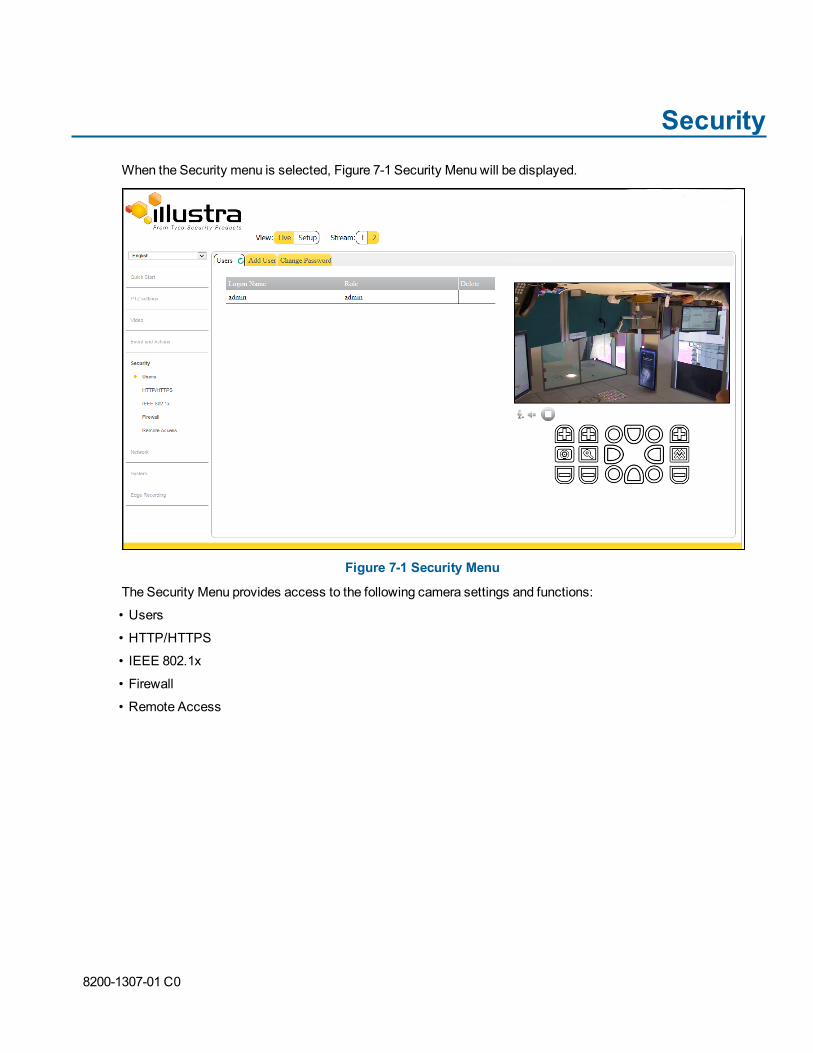
SecurityWhen the Security menu is selected, Figure 7-1 Security Menu will be displayed.
Figure 7-1 Security Menu
The Security Menu provides access to the following camera settings and functions:
• Users
• HTTP/HTTPS
• IEEE 802.1x
• Firewall
• Remote Access
8200-1307-01 C0

UsersIn this section you are able to add a user, change a user password and delete a user account. There are threelevels of access: admin, operator, and user.Note:
The default Username and Password are both admin. To maintain security, you should change the password onthe admin account.
View Current User AccountsView a list of the current user accounts assigned to the camera.
View User Accounts
Step Action
1 Select Setup on the GUI banner to display the setup menus.
2 Select Users from theSecuritymenu.
The current user accounts assigned to the camera will be displayed on theUser tab.
- End -
Add UserAdd a new user account to allow access to the camera.
Add a User
Step Action
1 Select Setup on the GUI banner to display the setup menus.
2 Select Users from theSecuritymenu.
3 Select theAdd User tab.
4 Enter a User Name in theName text box.
The username must start with a letter and can be followed by any alphanumeric values (a-z, A-Z, 0-9) andthe following special characters, underscore(_), dash(-), or dot(.)
5 Select aRole from the drop-down menu:
• operator• user
The default setting is 'admin'.
6 Enter a password in thePassword text box.
The password must start with an alphanumeric character and is case sensitive; it can containalphanumeric characters with a length of between 4 and 32 characters.
7 Enter the same password in theConfirm Password text box.
8 Select Apply to save the settings.
110

The new user account will now be displayed in the Users list on theUsers tab.
- End -
Changing the User Accounts PasswordChange the password of an existing user account.
Change User Password
Step Action
1 Select Setup on the GUI banner to display the setup menus.
2 Select Users from theSecuritymenu
3 Select theChange Password tab.
4 Select the user account from theName drop-down menu.
5 Enter the current password for the user account in theCurrent Password text box.
6 Enter the new password for the user account in theNew Password text box.
The password is case sensitive and can contain alphanumeric characters with a length of between 4 and32 characters.
7 Enter the same new password in theConfirm New Password text box.
8 Select Apply to save the settings.
- End -
Delete a User AccountDelete a user account from the camera.Note:
The default ‘admin’ account cannot be deleted.
Delete a User Account
Step Action
1 Select Setup on the GUI banner to display the setup menus.
2 Select Users from theSecuritymenu.
The Users tab displays.
3 Select to delete the corresponding user account.
You will be prompted to confirm the deletion.
4 Select OK to delete.
OR
5 Select Cancel.
Configuration Guide 111

Note:
An admin user account may not be deleted.
- End -
HTTP/HTTPSYou can select this option to use HTTP, HTTPS or both. The camera will automatically create an SSL certificatefile to use for HTTPS. It is possible to upload a custom SSL certificate if validation is required.
Specify HTTP Method
Step Action
1 Select Setup on the GUI banner to display the setup menus.
2 Select HTTP/HTTPS from theSecuritymenu.
The HTTP/HTTPS tab displays.
3 Select theHTTP Method using the radio buttons
• HTTP
• HTTPS
• Both
The default is Both.
- End -
Add a HTTPS Certificate
Step Action
1 Select Setup on the GUI banner to display the setup menus.
2 Select HTTP/HTTPS from theSecuritymenu
The HTTP/HTTPS tab displays.
3 Select theBrowse button for theSelect certificate file text box to navigate to the certificate location.
The Choose file dialog will be displayed.
4 Navigate to the location where the HTTP/HTTPS certificate has been saved.
Select the file and select Open.Note:
The certificate needs to match the camera ‘host name’.
5 Select Upload.
You will be prompted to confirm that you would like to upload the HTTP/HTTPS certificate.
112
6 Select OK to confirm the upload.
OR
Select Cancel.7 Select theView buttonto view the certificate.
- End -
Delete a HTTPS CertificateIf you delete the existing certificate, it will be replaced by a temporary substitute. The current browser session willbe lost and you will be required to log back in to the camera Web GUI.
Delete a HTTPS Certificate
Step Action
1 Select Setup on the GUI banner to display the setup menus.
2 Select HTTP/HTTPS from theSecuritymenu
The HTTP/HTTPS tab displays.
3 Select Delete.
The camera will display a “Restarting HTTPS Service” page with a progress bar showing the deletionprogress.
4 When the deletion has completed, the camera will return to the log in page.
- End -
IEEE 802.1xThe IEEE 802.1x security feature provides port based network access control—i.e., securing corporate networksfrom the attachment of unauthorized devices.
Authentication is carried out through use of the Extensible Authentication Protocol (EAP). Both PEAP and TLSmethods are supported.
Configure IEEE 802.1x Security
Step Action
1 Select Setup on the GUI banner to display the setup menus.
2 Select IEEE 802.1x from theSecuritymenu
TheEAP Settings tab is displayed.
3 Select theEnable IEEE802.1x check box to enable IEEE802.1x security .
OR
4 De-select theEnable IEEE802.1x check box to disable IEEE802.1x security.
The default is 'Disabled'.
5 Select theEAPOL Version from the drop-down menu.
Configuration Guide 113

6 Select theEAP Method using the radio buttons.
7 Enter the EAP identity name in theEAP Identify textbox.
8 Select Upload to navigate to theCA Certificate location.
The Choose file dialog will be displayed.
9 Navigate to the location where the certificate has been saved.
Select the file and select Open.
10 Select Upload.
The upload process will start.
Select View to review the certificate orDelete to remove it.
11 If PEAP is selected:
• Enter the required PEAP Password.OR
• If TLS is selected -
a Select Upload to navigate to theClient Certificate location.The Choose file dialog will be displayed.
b Navigate to the location where the certificate has been saved.
c Select the file and select Open.
d Select Upload.The upload process will start.Select View to review the certificate orDelete to remove it.
e Enter the requiredPrivate Key Password.
• SYN Cookie Verification.
- End -
FirewallA firewall may be enabled to perform address filtering to allow or deny specific IP and MAC addresses.
Enable/Disable Firewall
Step Action
1 Select Setup on the GUI banner to display the setup menus.
2 Select Address Filtering from theSecuritymenu
OR Select Address Filtering from theNetworkmenu.
3 Select Off to disable address filtering completely.
OR
Select Allow to allow address filtering for specified addresses
OR
Select Deny to deny address filtering for specific addresses.
The default setting is ‘Off’.
114

4 If address filtering has been set toAllow orDeny:
a Enter an IP or MAC Address to allow/deny in the IP or MAC Address text box in the followingformat xxx.xxx.xxx.xxx.
Note:
CIDR (Classless Inter-Domain Routing) is supported when using address filtering. If using a CIDRaddress use the following format xxx.xxx.xxx.xxx/xx.
b Select Add.
5 Select Apply to save the settings.
- End -
Editing an Address FilterEdit an existing address filter.
Edit an Address Filter
Step Action
1 Select Setup on the GUI banner to display the setup menus.
2 Select Firewall from theSecuritymenu
OR Select Firewall from theNetworkmenu.
3 Select theAddress Filtering tab.
4 Edit the IP or MAC Address in the IP or MAC Address text box.
5 Select Add to save the IP or MAC Address in the table.
6 Select Apply to turn address filtering on.
- End -
Deleting an Address FilterDelete an existing address filter.
Delete an Address Filter
Step Action
1 Select Setup on the GUI banner to display the setup menus.
2 Select Firewall from theSecuritymenu
OR Select Firewall from theNetworkmenu.
3 Select theAddress Filtering tab.
4 Select to delete the corresponding address filter.
- End -
Configuration Guide 115

ONVIFThe Web GUI allows ONVIF functionality to be managed at a high level. ONVIF Discovery Mode and UserAuthentication can be enabled or disabled.
• ONVIF Discovery Mode allows enabling or disabling discovery of the camera via ONVIF.
• ONVIF User Authentication allows the camera to accept ONVIF commands from all users or onlyauthenticated users. Enabling User Authentication ensures the camera will only execute commandsfrom authenticated users.
The separation of Discovery Mode and User Authentication allows the camera to be set up in a configuration thatsuits requirements for the network and users. The preferred discovery method for the camera is Illustra Connect,and this utilizes ONVIF discovery. It is therefore recommended that ONVIF Discovery Mode always be enabled.
ONVIF Discovery ModeEnable or disable ONVIF discovery on the camera.Enable/Disable ONVIF Discovery Mode
Enable/Disable ONVIF Discovery Mode
Step Action
1 Select Setup on the GUI banner to display the setup menus.
2 Select Remote Access from theSecuritymenu
The Remote Access tab displays.
3 Select theONVIF Discovery Mode check box to enable ONVIF Discovery Mode.
OR
Deselect ONVIF Discovery Mode check box to disable ONVIF Discovery Mode.
The default setting is ‘Enabled’.
- End -
ONVIF User AuthenticationUser authentication may be performed via ONVIF
Enable/Disable ONVIF User Authentication
Step Action
1 Select Setup on the GUI banner to display the setup menus.
2 Select Remote Access from theSecuritymenu
The Remote Access tab displays.
3 Select theONVIF User Authentication check box to enable ONVIF User Authentication.
OR
Deselect ONVIF User Authentication check box to disable ONVIF User Authentication.
The default setting is ‘Enabled’.
116

Network MenuWhen the Network menu is selected, Figure 8-1 Network Menu will be displayed.
Figure 8-1 Network Menu
The Network Menu provides access to the following camera settings and functions:
• TCP/IP
• FTP
• SMTP
• SNMP
• CIFS
• Dynamic DNS
8200-1307-01 C0
TCP/IPConfigure the IPv4 and IPv6 settings on the camera.
IPv4Configure the IPv4 settings for the camera.
Configure IPv4 Settings
Step Action
1 Select Setup on the GUI banner to display the setup menus.
2 Select TCP/IP from theNetworkmenu.
3 Select theEnable DHCP check box to enable DHCP (Dynamic Host Configuration Protocol) anddisable manual settings.
OR
Deselect Enable DHCP to disable DHCP and allow manual settings to be entered.
The default setting is ‘Disabled’.
4 If Enable DHCP has been disabled:
a Enter the IPv4 Address in the IPv4 Address text box in the form xxx.xxx.xxx.xxx.The default setting for the camera is ‘192.168.1.168’.
b Enter theNetwork Mask in the Network Mask text box xxx.xxx.xxx.xxx.The default setting is ‘255.255.255.0’.
c Enter theGateway IP address in Gateway text box xxx.xxx.xxx.xxx. The default setting is192.168.1.254.
d Enter thePrimary DNS Server in the Primary DNS Server text box xxx.xxx.xxx.xxx.
5 Select Apply to save the settings.
- End -
IPv6Enable or disable IPv6 on the camera.
Enable/Disable IPv6
Step Action
1 Select Setup on the GUI banner to display the setup menus.
2 Select TCP/IP from theNetworkmenu.
3 Select the IPv6 Enable check box to enable IPv6 on the camera.
OR
Deselect the IPv6 Enable check box to disable IPv6 on the camera.
The default setting is ‘Enabled’.
118

If IPv6 is enabled, the Link Local and DHCP address will be displayed beside ‘Current IPv6 Addresses’,if available.
- End -
Network Loss DetectionEnable the camera to detect when there is a network loss from the Network menu.
Note:
This feature is only available on the FlexZ camera.
Enable/Disable Network Loss Detection
Step Action
1 Select Setup on the GUI banner to display the setup menus.
2 Select TCP/IP from theNetworkmenu.
3 Select theEnable Network Loss Detection check box to enable Network Loss Detection on thecamera.
OR
Deselect theEnable Network Loss Detection check box to disable Network Loss Detection on thecamera.
The default setting is ‘Enabled’'.
- End -
FTPConfigure the FTP settings for the FTP server. This is required to send video files from triggered analytic alerts.FTP must be configured to enable FTP video alerts when using alarms and analytic alerts.Note:
FTP settings can also be configured via the Events and Actions menu. Refer to FTP on Page 99.
Configure FTP Server Settings
Step Action
1 Select Setup on the GUI banner to display the setup menus.
2 Select FTP from theNetworkmenu.
The FTP tab displays.
3 Select theEnable check box to enable FTP.
Text boxes on the tab become available for entry.
OR
Configuration Guide 119

Deselect theEnable check box to disable FTP.
The default setting is ‘Disabled’.
4 Enter the IP address of the FTP Server in the FTP Server text box.
5 Enter the FTP port in the FTP Port text box.
The default setting is 21.
6 Enter the FTP username in theUsername text box.
7 Enter the FTP password in thePassword text box.
8 Enter the FTP upload path in theUpload Path text box.Note:
• When entering the upload path the following format should be used: /folder/
• Refer to Test FTP Settings on Page 120 to confirm that the FTP settings are working asexpected.
- End -
Test FTP SettingsTest that the settings set in Configure FTP Server Settings on Page 119 have been configured correctly.
Test the FTP Settings
Step Action
1 Select Setup on the GUI banner to display the setup menus.
2 Select FTP from theEvents and Actionsmenu.
3 Select Test.A sample text file will be sent to the specified FTP destination to confirm that FTP settings are correct.
A message will display and report if the delivery has been successful.Note:
Test FTP settings may also be configured through the Events and Actions menu.
- End -
SMTPConfigure the SMTP settings to allow e-mail alerts to be sent from the camera when an alarm or analytic alert istriggered.Note:
SMTP settings must be configured to enable email alerts when using alarms and analytic alerts. SMTP can alsobe configured via the Events and Actions menu. Refer to SMTP on Page 98.
120

Configure SMTP Settings
Step Action
1 Select Setup on the GUI banner to display the setup menus.
2 Select SMTP from theNetworkmenu.
3 Select theEnable SMTP check box to enable SMTP.
Text boxes on the tab become available for entry.
OR
Deselect theEnable check box to disable SMTP.
The default setting is ‘Disabled’.
4 Enter the IP Address of the mail server in theMail Server text box.
5 Enter the server port in theServer Port text box.
The default setting is ‘25’.
6 Enter the from email address in the From Address text box.
7 Enter the email address to send email alerts to in theSend Email to text box.
8 Select Apply to save the settings.Note:
Refer to Test SMTP Settings on Page 121 to confirm that the SMTP settings are working as expected.
- End -
Test SMTP SettingsTest that the settings set in Configure SMTP Settings on Page 121 have been configured correctly.
Test the SMTP Settings
Step Action
1 Select Setup on the GUI banner to display the setup menus.
2 Select SMTP from theNetworkmenu.
TheSMTP tab displays.
3 Select Test.A message will display and report if the connection has been successful.
- End -
SNMPThe camera features support for the Simple Network Management Protocol making it easier to manage on an IPnetwork.
The SNMP support includes support for V2 and V3. Using V2 means no authentication is required to access thedata and results are unencrypted. V3 offers enhanced encryption and authentication security features.
Configuration Guide 121

Configure SNMP Settings
Step Action
1 Select Setup on the GUI banner to display the setup menus.
2 Select SNMP from theNetworkmenu.
3 Enter a location reference in the Location text box.
4 Enter an SNMP managing contact reference in theContact text box.
5 If usingV2:
a Select theEnable V2 check box.
b Enter the authorized ID for reading SNMP data in theRead Community text box.
c Enter the Trap Community.
d Enter the Trap Address.
e Select Apply.
OR
If usingV3:
a Select theEnableV3 check box.
b Enter theRead User.c Select theAuthentication Type using the radio buttons: MD5 or SHA.
d Enter the Authentication Password
e Select theEncryptionType using the radio buttons: DES or AES.
f Enter theEncryption Password
g Select Apply.
- End -
CIFSConfigure the CIFS settings to allow files generated from the camera to be directed to network attached filestorage via the Common Internet File System (CIFS) protocol. This supplements existing distribution methodssuch as FTP, SMTP, and email.Note:
CIFS settings can also be configured via the Events and Actions menu. Refer to CIFS on Page 100
Configure CIFS Settings
Step Action
1 Select Setup on the GUI banner to display the setup menus.
2 Select Network from theSetup menu.
3 Select theCIFS tab.
4 Select theEnable CIFS check box to enable CIFS.
122

Text boxes on the tab become available for entry.
OR
Deselect theEnable check box to disable CIFS.
The default setting is ‘Enabled’.
5 Enter the network path in theNetwork Path text box:
Sample path: //192.168.185.159/CIFS.
6 Enter the domain name in theDomain Name text box.
7 Enter the username in theUsername text box.
8 Enter the password in thePassword text box.
9 Select Apply to save the settings.Note:
Refer to Test CIFS Settings on Page 123 to confirm that the CIFS settings are working as expected.
- End -
Test CIFS SettingsTest that the settings set in Configure CIFS Settings on Page 122 have been configured correctly.
Test the CIFS Settings
Step Action
1 Select Setup on the GUI banner to display the setup menus.
2 Select Network from theSetup menu.
3 Select theCIFS tab.
4 Select Test.A sample text file will be sent to the specified CIFS destination to confirm that CIFS settings are correct.
- End -
Dynamic DNSDynamic DNS (Domain Name System) is supported for updating, in real time, a changing IP address on theInternet to provide a persistent domain name for a resource that may change location on the network. In thissituation, the camera talks only to the DHCP server, and the DHCP server is responsible for updating the DNSserver. The camera sends its hostname to the DHCP server when requesting a new lease and the DHCP serverupdates the DNS records accordingly. This is suitable for an intranet style configuration where there is an internalDHCP and DNS service and the user wants to access their camera only within their own network.
By default, when making a DHCP request the camera will transmit its hostname as part of the DHCP request.This option is not user configurable. The camera's hostname matches the configurable parameter “camera name”on the web GUI. Any DHCP request will contain the camera's hostname for the DHCP server to use to forward toan appropriate DNS server.
Configuration Guide 123

Dynamic DNSConfigure the Dynamic DNS settings for the camera.
Configure Dynamic DNS
Step Action
1 Select Setup on the GUI banner to display the setup menus.
2 Select Dynamic DNS from theNetworkmenu.
TheDynamic DNS tab displays.
3 Select theService Enable check box to enable Dynamic DNS.
Other text boxes on the tab become available for entry.
OR
Deselect Service Enable check box to disable Dynamic DNS.
The default setting is ‘Disabled’.
4 If DNS has been enabled:
a Enter the Camera Alias in the text box.
b Select a Service Provider from the list:
• Dyndns.org (Dynamic)• Dyndns.org (Custom)• No-IP• Change IP
c Enter aUsername in the text box.
d Enter aPassword in the text box.
5 Select Apply to save the settings.
- End -
124

SystemWhen the System menu is selected, Figure 9-1 System Menuwill be displayed.
Figure 9-1 System Menu
The System Menu provides access to the following camera settings and functions:
• Maintenance
• Date Time
• Audio
• TV System
• Logs
• About
Configuration Guide 125

MaintenanceThe Maintenance menu allows you to restore the camera settings to factory default, reboot the camera and applya firmware upgrade.
ResetNote:
Network settings, presets, patterns and sequences can be retained if required.
Resetting the Camera
Step Action
1 Select Setup on the GUI banner to display the setup menus.
2 Select Maintenance from theSystem menu.
3 Select theMaintenance tab.
4 Select thePreserve IP address check box to retain the current network settings during the camerareset.
OR
Deselect thePreserve IP address check box to restore the default networking settings.
The default setting is ‘Disabled’.
5 Select thePreserve presets, patterns and sequences check box to retain the current presets, patternsand sequences during the camera reset.
OR
Deselect thePreserve presets, patterns and sequences check box to remove existing presets,patterns and sequences.
The default setting is ‘Disabled’.
6 Select ResetYou will be prompted to confirm the camera reset.
7 Select OK to confirm. The Web GUI will display a “Camera Resetting” page with a progress bar showingthe reset progress.
When the camera is restarted it will take 2 - 3 minutes until it is online and ready to be accessed andcontrolled
OR
Select Cancel.8 The Log in page will be displayed.
- End -
126

RebootTo perform a physical reboot of the camera:
Reboot the Camera
Step Action
1 Select Setup on the GUI banner to display the setup menus.
2 Select Maintenance from theSystem menu.
3 Select theMaintenance tab.
4 Select Reboot.You will be prompted to confirm the camera reboot.
5 Select OK to confirm.
The Web GUI will display a “Camera Rebooting” page with a progress bar showing the reboot progress.
When the camera is restarted it will take 2 - 3 minutes until it is online and ready to be accessed andcontrolled.
OR
Select Cancel.6 The Log in page will be displayed.
- End -
Camera UpgradeThe camera can be upgraded using firmware provided by Illustra. Alternatively, the camera can also be upgradedusing Illustra Connect. Refer to the Illustra Connect User Guide for further information.
Note:
All existing camera settings are maintained when the firmware is upgraded.
CautionYou should only use firmware that has been provided by Illustra. Using any other firmware may cause amalfunction and damage the camera.
Upgrade Camera Firmware
Step Action
1 Select Setup on the GUI banner to display the setup menus.
2 Select Maintenance from theSystem menu.
3 Select theMaintenance tab.
4 Select Browse next to theSelect firmware image file text box.
Configuration Guide 127

The Choose file to Upload dialog will be displayed.
5 Navigate to the location where the firmware file has been saved.
6 Select the firmware file and then select theOpen button.
7 Select Upload.
The file transfer will begin.
Do not disconnect power to the camera during the upgrade process. The camera restarts automaticallyafter the upgrade has been completed, which can take from 1 to 10 minutes.
The Log in page will be displayed.
- End -
Backup/RestoreBack up the camera data and restore from a previously saved data file. The configuration settings of the cameracan be saved to a data file in a specified location and then used to restore the camera configuration.
Note:
A saved backup data file created on a camera is camera specific and cannot be used to restore the settings on adifferent camera.
Back up Camera Data
Step Action
1 Select Setup on the GUI banner to display the setup menus.
2 Select Maintenance from theSystem menu.
3 Select theBackup/Restore tab.
4 Select Backup.
You will be prompted to save the backup file.
5 Select the location to save the backup file.
6 Select Save.
- End -
Restore Camera from Backup
Step Action
1 Select Setup on the GUI banner to display the setup menus.
2 Select Maintenance from theSystem menu.
3 Select theBackup/Restore tab.
4 Select theBrowse button next to theSelect saved data file text box.
The Choose file to Upload dialog will be displayed.
128

5 Navigate to the location where the backup file has been saved.
6 Select the backup file and then select theOpen button.
7 Select Upload.
You will be prompted to confirm that you would like to upload the backup file.
8 Select OK to confirm the backup .
Or
Select Cancel.Do not disconnect power to the camera during the restore process. The camera restarts automaticallyafter the restore has been completed, which can take from 1 to 10 minutes.
The Log in page will be displayed.
- End -
Date/TimeSet the date and time on the camera.
Note:
Date and Time can also be configured in theQuick Startmenu. Refer to Date Time on Page 46.
Configuring the Date and Time
Step Action
1 Select Setup on the GUI banner to display the setup menus.
2 Select Date Time from theSystem menu.
3 Select the Time 24-hour check box to enable the 24-hour clock.
Or
Deselect the Time 24-hour check box to enable the 12-hour clock.
The default setting is ‘24-hour’.
4 Select theDate Display Format from the drop-down menu:
• DD/MM/YYYY• MM/DD/YYYY• YYYY/MM/DD
The default setting is ‘YYYY/MM/DD’.
5 Select the Time Zone from the drop-down menu.
The default setting is ‘(GMT-05:00) Eastern Time (US & Canada)'.
6 Select theSet Time setting by selecting a radio button:
• Manually• via NTP
Configuration Guide 129

The default setting is 'Manually'.
7 If you select 'Manually' in step 6:
a Select the Date (DD/MM/YYYY) using the drop-down menus.
b Select the Time (HH:MM:SS) using the drop-down menus.
8 If you select 'via NTP' in step 6:
• Enter theNTP Server Name in the text box.
- End -
AudioFrom this tab, you can enable and configure audio inputs and audio outputs on the camera.
Configure Audio Input
Step Action
1 Select Setup on the GUI banner to display the setup menus.
2 Select Audio from theSystem menu.
3 Select theAudio Input tab.
4 Select the Input Enable check box to enable the audio input settings.
Or
Deselect the Input Enable check box to disable audio input settings.
The default setting is ‘Disabled’.
5 Select one of the following values forAudio Codec:• G711A
• G711u
• G726
• AAC
• PCM
6 Use the slider bar to select the Input Volume.
Values range from 1 to 100.
7 Select Apply to save your changes.
- End -
Configuring Audio Output
Step Action
1 Select Setup on the GUI banner to display the setup menus.
2 Select Audio from theSystem menu.
3 Select theAudio Out tab.
130

4 Select theOutput Enable check box to enable the audio output settings.
Or
Deselect theOutput Enable check box to disable audio input settings.
The default setting is ‘Disabled’.
5 If Output Enable has been enabled, use the slider bar to select the Output Volume.
Values range from 1 to 100.
6 Select Apply to save your settings.
- End -
TV SystemYou can choose between having the TV System operate through NTSC or PAL format depending on which formatsuits your location best. NTSC is used predominantly in America and Asia. PAL is used in most of Europe.Note:
Changes to TV System will affect both IP and Analogue stream if supported.
Enable TV System
Step Action
1 Select Setup on the GUI banner to display the setup menus.
2 Select TV System from theSystem menu.
3 Select the TV System you would like to use from the dropdown menu:
• NTSC• PAL
4 Select Apply to save your settings.
- End -
LogsInformation is provided on system, boot and audit logs created by the camera.
System LogThe system log gives the most recent messages from the unix/var/log/messages file. Information will include thefollowing:
• Messages about system behavior such as process startup/shutdown.
• Warnings about recoverable problems that processes encounter.
Configuration Guide 131

• Error messages where processes encounter problems they cannot fix. This does not mean that theprocess will not continue to work, only that it encountered an issue it could do nothing about.
Display System Log
Step Action
1 Select Setup on the GUI banner to display the setup menus.
2 Select Logs from theSystem menu.
Select the System Log tab.
3 Select Refresh to refresh the log with the most up-to-date information.
- End -
AboutThe About menu provides the following camera information:
• Camera Name
• Model
• Product Code
• Manufacturing Date
• Serial Number
• MAC Address
• Firmware Version
• Hardware VersionNote:
The Flex PTZ camera's About menu will display the following additional information:
• Switch version
• Main version
• Module version
Display Model Information
Step Action
1 Select Setup on the GUI banner to display the setup menus.
2 Select About from theSystem menu.
The model tab displays.
3 View the information.
- End -
132

Edit Camera Name
Step Action
1 Select Setup on the GUI banner to display the setup menus.
2 Select About from theSystem menu.
The model tab displays.
3 Edit the name in theCamera Name textbox.
4 Select Apply to save your changes.
- End -
Configuration Guide 133

Edge RecordingWhen the Edge Recording menu is selected, Figure 10-1 Edge Recording Menu will be displayed.
Figure 10-1 Edge Recording Menu
The Edge Recording Menu provides access to the following camera settings and functions:
• SD Card Management
• Record Settings
• Event Download
Configuration Guide 134

SD Card ManagementEdge recording provides the ability to save recorded video to a SD card or microSD card. Video can be configuredto be recorded based on an event.
Check below to see which SD card formats can be used with each camera:
• FlexZ outdoor mini dome: SDXC up to 64GB support
• FlexZ indoor mini dome: microSDHC up to 64GB support
• Flex PTZ: microSDHC up to 64GB support
• Pro 12MP Fisheye: microSDHC up to 64GB support
CautionIf you wish to use the microSD card or SD card, it must be present when the camera boots up or it will requiremounting manually via the WebGUI.
The following provides details of functions available without an SD card or microSD card and when using one.
Features Available with a SD Card or microSD Card
• Current faults notifications are displayed on camera if an alarm is triggered.
• Video/Audio and screenshot are saved to the SD card.
• SMTP notifications can be sent.
• FTP uploads of video can be sent.
Without a SD Card or microSD Card
• Current faults notifications are displayed on camera if an alarm is triggered.
• Recording of video is not possible without an SD card. If recording has not been selected thecamera will just sent snapshots.
Verifying and Formatting the SD Card or microSD CardWhen inserting a SD card or microSD card, the card should mount automatically. To verify that the mount wassuccessful, check the Status field on the SD Card Management tab.
Verify the SD Card or microSD Card Mount Was Successful
Step Action
1 Select Setup on the GUI banner to display the setup menus.
2 Select SD Card Managementmenu from theEdge Recording menu.
3 View theStatus field.
- End -
135

Format the Mounted SD Card or microSD Card
Step Action
1 Select Setup on the GUI banner to display the setup menus.
2 Select SD Card Managementmenu from theEdge Recording menu.
3 Select Format.A Format SD card dialog box will warn you that formatting the SD card will delete all information on thecard.
4 Select OK to confirm.
OR
5 Select Cancel.
- End -
Removing the SD Card or microSD CardIf at any stage you need to remove the SD card or microSD card from the camera, one of the following twoprocedures should be used:
• Remove the SD card or microSD card by powering down the camera - Use this procedure if youdon’t have access to the web GUI and are unable to unmount the SD card or microSD card beforeremoval.
• Unmount the SD card or microSD card for removal - Use this procedure when you are unable toaccess the power supply to the camera.
Remove the SD Card or microSD Card by Powering down the Camera
Step Action
1 Turn off the camera by disconnecting the power supply.
2 Remove the SD card or microSD card from the camera.
3 Reconnect the power supply and power up the camera.
When the camera is restarted, it checks its functionality by performing a homing routine.
- End -
Unmount the SD Card or microSD Card for Removal
Step Action
1 Select Setup on the GUI banner to display the setup menus.
2 Select SD Card Managementmenu from theEdge Recording menu.
3 Select Unmount.You will be prompted to confirm the unmounting.
4 Select OK to confirm.
OR
Configuration Guide 136

5 Select Cancel.Remove the SD card or microSD card from the camera.
- End -
Record SettingsSelect which video stream to use for alarm video and configure pre and post event durations for the playable videoclip. The camera can record video generated from MD and DIO events.
Configure Record Settings
Step Action
1 Select Setup on the GUI Banner to display the setup menus.
2 Select Record Settings from theEdge Recording menu.
3 Select Enable Event Record to allow the camera to create a playable video clip.
OR
Deselect Enable Event Record to disable the feature.
4 If Enable Event Record has been enabled:
a Select the required video stream from theRecord Source drop-down menu.Refer to Configure the Video Stream settings on Page 62.
b Select the Pre Event seconds from thePre Event (secs) drop-down menu. Values range from 0 to10.The default setting is 5 seconds.
c Select the Post Event seconds from thePost Event (secs) drop-down menu. Values range from 0 to10.The default setting is 5 seconds.
5 Select Apply to save.
- End -
Event DownloadIf an event action has record mode enabled, when it is triggered, the associated video will be logged in the eventdownload table. From there it can later be downloaded from a SD card or microSD card using the specified uploadprotocol.
Note:
An event action must have record mode enabled to be logged and downloaded. This is configured inEventActions under theEvents and Actionsmenu. Refer to Create an Event Action on Page 102.
137