ILD Meeting, Sendai, 7/3/2008Mark Thomson1 LDC in Mokka Mark Thomson University of Cambridge.
26
ILD Meeting, Sendai, 7/3/2008 Mark Thomson 1 LDC in Mokka Mark Thomson University of Cambridge
-
Upload
ophelia-hart -
Category
Documents
-
view
216 -
download
0
Transcript of ILD Meeting, Sendai, 7/3/2008Mark Thomson1 LDC in Mokka Mark Thomson University of Cambridge.

ILD Meeting, Sendai, 7/3/2008 Mark Thomson 1
LDC in MokkaMark Thomson
University of Cambridge

ILD Meeting, Sendai, 7/3/2008 Mark Thomson 2
Overview During the last two months – a lot of progress in defining new LDC detector models (LDC, and LDC’) Changes to most sub-detector drivers !
More realism (good/bad) More flexibility
Set the deadline for finalising sub-detector drivers for this coming Monday At Wednesday’s optimisation phone meeting – will fix (?) model for mass GRID-based generation At that stage, will only make changes to fix bugs rather than improve the model
motivated by need to start production Philosophy:
driven by needs of global detector optimisation but also want to make as useful as possible for sub-detector groups (VTX, HCAL, Si-tracking) provided does not impact the main aim

ILD Meeting, Sendai, 7/3/2008 Mark Thomson
LDC detector in MokkaLDC01_05Sc LDC V5
Close to, but not exactly the same as, proposed LDC model Here, will concentrate on main changes
ILD Meeting, Sendai, 7/3/2008 Mark Thomson
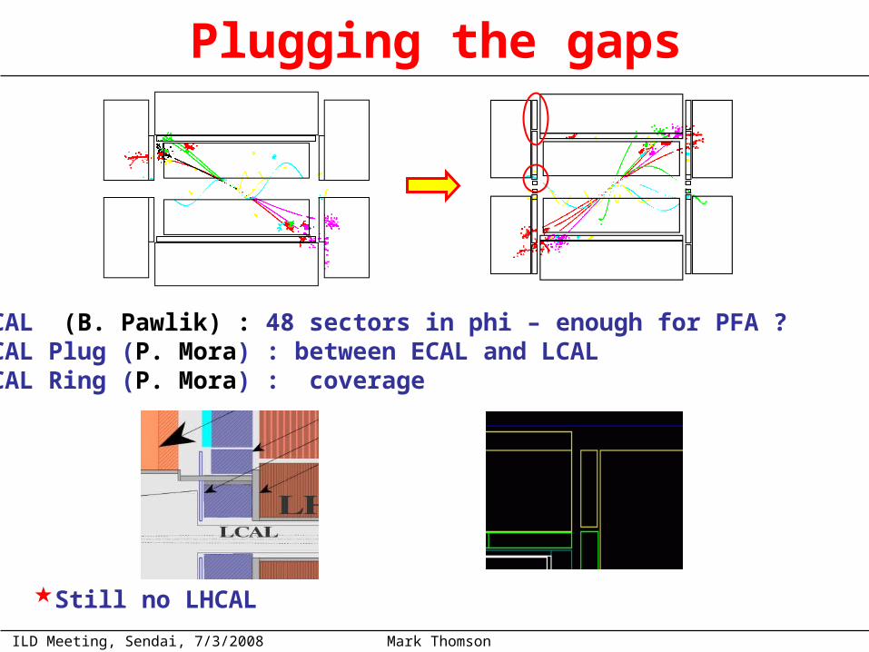
Plugging the gaps
LCAL (B. Pawlik) : 48 sectors in phi – enough for PFA ? ECAL Plug (P. Mora) : between ECAL and LCAL HCAL Ring (P. Mora) : coverage
Still no LHCAL
ILD Meeting, Sendai, 7/3/2008 Mark Thomson
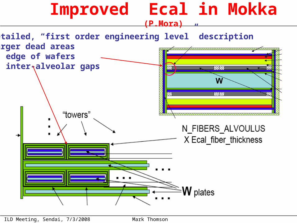
Improved Ecal in Mokka (P.Mora)
Detailed, “first order engineering level” description Larger dead areas
edge of wafers inter-alveolar gaps

ILD Meeting, Sendai, 7/3/2008 Mark Thomson
Impacts “performance”
LDC01_05ScDRW
LDC01Sc
DRW
ECAL
HCAL Confusion Other Total
LDC00Sc 0.07 0.17 0.11 0.09 0.235
LDC01_05Sc 0.14 0.17 0.12 0.09 0.267
Can estimate contributions to PFA performance (45 GeV jets)
Effect will be reduced somewhat in current (smaller gaps than LDC01_05Sc) BUT raw ECAL resolution will be degraded
and PFA performance degraded Will need to correct for effects of gaps in software ! This is a significant complication – is this what we want ?

ILD Meeting, Sendai, 7/3/2008 Mark Thomson
Improved HCAL (A. Lucacci)
3cm
Increased realism/more flexibility Introduced additional caps in middle of module
not small ~ 3cm “gaps” line up and point to IP
Also introduced realistic scintillator tiling
3cm
Comments/Questions: Impact of large gaps on PFA is not known
could affect clustering Gaps may be realistic, but very much doubt we would design a real HCAL with this pointing gap geometry Suggest reducing gaps to ~1cm for mass generation In parallel, study impact on PFA Win-win approach:
if 3cm gaps don’t matter, performance with 1cm gaps is ~same if they do matter, need to revisit design, but global study not affected
ILD Meeting, Sendai, 7/3/2008 Mark Thomson
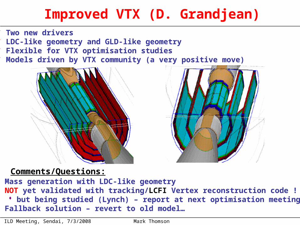
Improved VTX (D. Grandjean) Two new drivers LDC-like geometry and GLD-like geometry Flexible for VTX optimisation studies Models driven by VTX community (a very positive move)
Comments/Questions: Mass generation with LDC-like geometry NOT yet validated with tracking/LCFI Vertex reconstruction code !
but being studied (Lynch) – report at next optimisation meeting Fallback solution – revert to old model…
ILD Meeting, Sendai, 7/3/2008 Mark Thomson
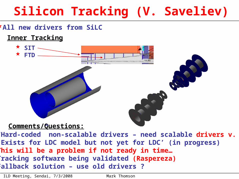
Silicon Tracking (V. Saveliev)
Inner Tracking SIT FTD
All new drivers from SiLC
Comments/Questions: “Hard-coded” non-scalable drivers – need scalable drivers v. soon Exists for LDC model but not yet for LDC’ (in progress) This will be a problem if not ready in time… Tracking software being validated (Raspereza) Fallback solution – use old drivers ?

ILD Meeting, Sendai, 7/3/2008 Mark Thomson
Silicon Tracking contOuter TrackingSET : between TPC and ECAL barrel
Silicon + carbon support2 XUV layers × 0.65 % X0
Silicon – carbon sandwich3 XUV layers × 0.65 % X0
Comments/Questions: “Hard-coded” non-scalable drivers – need scalable drivers v. soon May cause problems with ECAL driver Are the SET/ETD part of the initial “baseline” ? Tracking software does not (yet) use ETD or SET:
Inclusion increases lever arm for track–calorimeter extrapolation How thick are these models ? At this stage inclusion can only degrade detector performance Balanced by potential use for SiLC tracking studies
Fallback solution – do not include
ETD : behind TPC end-planes

ILD Meeting, Sendai, 7/3/2008 Mark Thomson 11
Decision Time…
HCAL model : ready in time ? SET/ETD : will degrade track-cluster matching
could be particularly damaging in endcap once included in the tracking this may not be an issue but this won’t happen on timescale of first optimisation
Some concerns:
Want to finalise model for mass generation very soon
ILD Meeting, Sendai, 7/3/2008 Mark Thomson 12
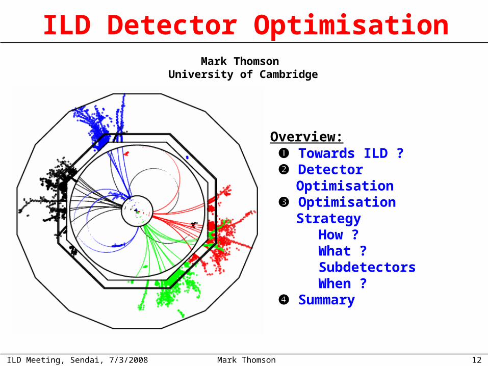
ILD Detector OptimisationMark Thomson
University of Cambridge
Towards ILD ? Detector Optimisation Optimisation Strategy How ? What ? Subdetectors When ? Summary
Overview:
ILD Meeting, Sendai, 7/3/2008 Mark Thomson 13
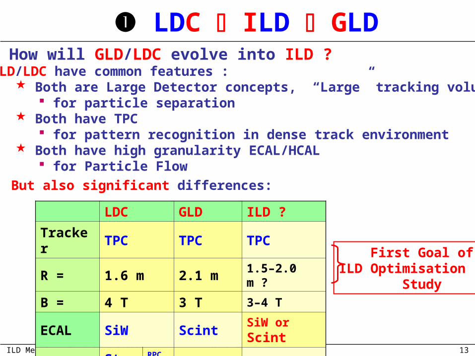
LDC ILD GLD How will GLD/LDC evolve into ILD ?
LDC GLD ILD ?
Tracker TPC TPC TPC
R = 1.6 m 2.1 m 1.5–2.0 m ?
B = 4 T 3 T 3–4 T
ECAL SiW Scint SiW or Scint
HCAL Steel RPC
Scint yesScint
GLD/LDC have common features : Both are Large Detector concepts, “Large” tracking volume
for particle separation Both have TPC
for pattern recognition in dense track environment Both have high granularity ECAL/HCAL
for Particle Flow
First Goal ofILD Optimisation Study
But also significant differences:

ILD Meeting, Sendai, 7/3/2008 Mark Thomson 14
Detector Optimisation Study
“Investigate the dependence of the physics performance of the ILD detector on basic parameters such as the TPC radius and B-field. On the basis of these studies and the understanding of any differences observed the WG, will make recommendations for the optimal choice of parameters for the ILD detector. It is the responsibility of the WG convenors to organize this work, while the steering board will assist them in executing the charge.”
Charge of Detector Optimisation Working Group:
Initial Goal (pre-December 2007): First results from detector optimisation studies by May 2008 .
Convincingly demonstrate the ILD can meet ILC physics requirements Justifiable set of detector parameters optimised on scientific grounds GLD & LDC ILD
in the first stage aim to:
New Goal (for discussion): LoI timescales have been extended by 6 months As a consequence LDC have spent more time refining simulation But want to make first ILD baseline ~end of Summer 2008 Want for first results from detector optimisation studies on this timescale
Whatever happens this is not the end of the story ! Optimisation/Physics studies will continue through 2010/2012

ILD Meeting, Sendai, 7/3/2008 Mark Thomson 15
Optimisation Strategy
Detector parameters optimised for physics performance Studies as realistic as possible:
Study signal + all SM background Monte Carlo Ideally include machine and underlying event backgrounds
Use full detector simulation and reconstruction the tools now exist for both LDC and GLD Aim to parameterize “performance” vs. RTPC, B, etc… THEN use cost model to optimize
Basic Idea:
Questions: For LoI-study what parameters are we optimising ? In practice, how we will do this ? In detail, on what timescale do things need to happen ? What are the open questions ?
This is an ambitious goal ! Need to be realistic about what can be done by end Summer 2008 Need to collaborate effectively Plans will evolve with experience…
(hard)

ILD Meeting, Sendai, 7/3/2008 Mark Thomson 16
Optimisation Strategy : What ?
Study parameter space “between” LDC and GLD To study the full matrix of detector parameter space (R, B, L, …) would prove very time consuming – be realistic Initially concentrate on main parameters (R and B)
will need to do this to exercise full reconstruction chain
Optimisation priorities
Enough to start to define ILD But also want to investigate impact of sub-detector design

ILD Meeting, Sendai, 7/3/2008 Mark Thomson 17
Optimisation Studies : How ?
Simulation:
Reco: MARLIN
Mokka
LDC
Satellites
Jupiter
GLD
LCIO
Currently GLD and LDC use different G4 simulations/ reconstruction frameworks (this is not ideal but it is what we have got) Connected by common data format
Given timescale, decided to perform ILD detector studies in context of both GLD and LDC
Study physics performance dependence by changing parameters of GLD and LDC – provide some cross check of conclusions
Can directly compare results using common LCIO data format…
ILD

ILD Meeting, Sendai, 7/3/2008 Mark Thomson 18
LDC’/GLD’ Common Parameters
Sub-Detector Parameter GLD LDC GLD’ LDC’
TPC Rinner (m) 0.45 0.30 0.45 0.30
Router (m) 2.00 1.58 1.80 1.80
Zmax (m)* 2.50 2.16 2.35 2.35
Barrel ECAL Rinner (m)** 2.10 1.60 1.82 1.82
Material Sci/W Si/W Sci/W Si/W
Barrel HCAL Material Sci/W Sci/Fe Sci/Fe Sci/Fe
Endcap ECAL Zmin (m)*** 2.80 2.30 2.55 2.55
Solenoid B-field 3.0 4.0 3.50 3.50
VTX Inner Layer (mm) 20 16 18 18
PROPOSE TO START GENERATION WITH LDC’
Defined and will simulate a common point: LDC’ and GLD’ : a larger version of LDC and a smaller version of GLD direct point of comparison
ILD Meeting, Sendai, 7/3/2008 Mark Thomson 19
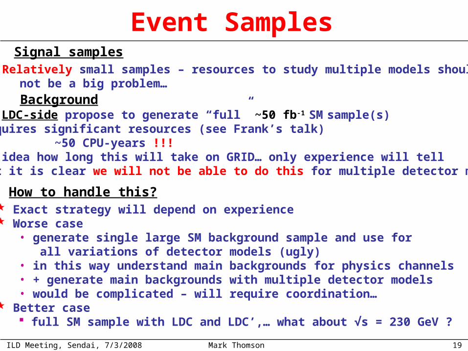
Event SamplesSignal samples
On LDC-side propose to generate “full” ~50 fb-1 SM sample(s) Requires significant resources (see Frank’s talk) ~50 CPU-years !!! No idea how long this will take on GRID… only experience will tell But it is clear we will not be able to do this for multiple detector models
How to handle this? Exact strategy will depend on experience Worse case
• generate single large SM background sample and use for all variations of detector models (ugly)• in this way understand main backgrounds for physics channels• + generate main backgrounds with multiple detector models• would be complicated – will require coordination…
Better case full SM sample with LDC and LDC’,… what about √s = 230 GeV ?
Background
Relatively small samples – resources to study multiple models should not be a big problem…

ILD Meeting, Sendai, 7/3/2008 Mark Thomson 20
LDC’ LDC LDC – GLD sized
Want to compare different models Need to ensure that all samples are generated in comparable manner Many pitfalls
• gluon radiation• fragmentation • generator settings
Need to ensure all samples reconstructed correctly with appropriate configuration files, again there are pitfalls:
• calibration• appropriate steering
All files Generated/Reconstructed centrally : GRID
Detector models/Signal Samples
Signal samples: what models do we generate/and in what order ?
agreed
?
Then what ? Can probably defer this discussion for now… the above will take 1/x of a Jovian year (x>1)
3 Points in B, R
Signal samples: generation/reconstruction, where ?
?
ILD Meeting, Sendai, 7/3/2008 Mark Thomson 21
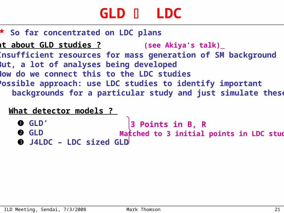
So far concentrated on LDC plans
GLD LDC
What about GLD studies ? (see Akiya’s talk) Insufficient resources for mass generation of SM background But, a lot of analyses being developed How do we connect this to the LDC studies Possible approach: use LDC studies to identify important backgrounds for a particular study and just simulate these…
What detector models ?
GLD’ GLD J4LDC – LDC sized GLD
3 Points in B, RMatched to 3 initial points in LDC study ?
ILD Meeting, Sendai, 7/3/2008 Mark Thomson 22
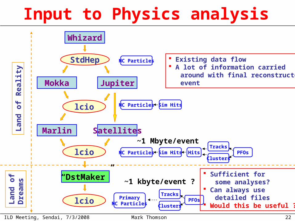
Input to Physics analysisL
and
of
Rea
lity
Lan
d o
fD
ream
s
lcio
StdHep
Whizard
Mokka Jupiter
Marlin Satellites
lcio
“DstMaker”
lcio
MC Particles
MC Particles Sim Hits
MC Particles Sim Hits HitsTracks
ClustersPFOs
PrimaryMC Particles
Tracks
ClustersPFOs
~1 Mbyte/event
~1 kbyte/event ? Sufficient for some analyses? Can always use detailed files Would this be useful ?
Existing data flow A lot of information carried around with final reconstructed event

ILD Meeting, Sendai, 7/3/2008 Mark Thomson 23
Initial studies will concentrate on global parameters, i.e. B, R These are major cost drivers But also want to investigate important aspects of sub-detectors
Optimisation Strategy : Sub-detectors
Generating a full set of SM/signal samples with even one detector model will be non-trivial Will not be possible to generate full SM sets for many models Sub-detector groups need to come up with a wish-list:
What detector parameters need to be studied ? Minimal set of samples to be used (i.e. important signal) Limited resources - need to be realistic in what can be achieved
Need alternative sub-detector models in Mokka/Jupiter - follow the lead of the Vertex community Has to be responsibility of detector groups
e.g. Marcel’s suggestion of heavy tracker
ILD Meeting, Sendai, 7/3/2008 Mark Thomson 24
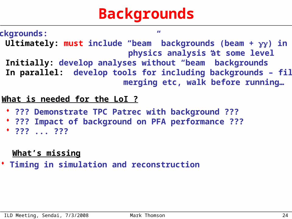
BackgroundsBackgrounds:
Ultimately: must include “beam” backgrounds (beam + ) in physics analysis at some level Initially: develop analyses without “beam” backgrounds In parallel: develop tools for including backgrounds – file merging etc, walk before running…
What is needed for the LoI ?
??? Demonstrate TPC Patrec with background ??? ??? Impact of background on PFA performance ??? ??? ... ???
What’s missing Timing in simulation and reconstruction

ILD Meeting, Sendai, 7/3/2008 Mark Thomson 25
Task “Deadline” Status
Final version of Letter of Intent Mar 09
Refine results and LoI performance section Jan 09
First draft of LoI physics performance section Nov 08
Define ILD Baseline Parameters ! Sep 08
Physics Optimisation Results June 08
Start of mass reconstruction of physics samples Apr 08
Validation of reconstruction software 1st Apr 08 Started
Start of mass generation of physics samples 15st Mar 08
Preliminary results for TILC 08 (Sendai) Mar 08 GLD started
Status reports of Physics Studies ILD mtg. (Zeuthen)
Jan 08
GLD’/LDC’ in Mokka/Jupiter 1st Dec 07 Done
Define GLD’/LDC’ 15th Nov 07 Done
Check Mokka/Jupiter LCIO compatibility 15th Nov 07
LDC baseline in Mokka 15th Nov 07 Done
GLD baseline in Jupiter 15th Nov 07 Done
Define LDC v5 baseline parameters Done
Define GLD baseline parameters Done
Start Developing physics analysis ASAP In progress
Timescales : can we do this ?
Production
STRAWMANTIMELINE
1 year

ILD Meeting, Sendai, 7/3/2008 Mark Thomson 26
Summary There is a lot of ground to cover in the next months Need to demonstrate ILD can deliver the required physics performance and determine “optimal” detector parameters “sub-detector community” becoming integrated into the simulation/physics studies – good news ! Given the timescale we cannot expect to do everything in this first phase (we are not in the EDR phase yet) Important not to be overly ambitious – if by ~Sept 2008 we have well-justified choice of the detector’s size and B-field based on physics we should view this as a success Hope for more, e.g. improved understanding of sub-detector design on physics performance c.f. sub-detector performance