IIIIIIIII - apps.dtic.mil
56
USACE:L Tedu*l Report M-91/19 ApIl 1991 ILIIAMyCorps Reiseah AD-A237 044 IIIIIIIII Key Issues in the Application of Existing Conventional High Speed Railroad Technologies to Mobilization by Donald E. Plotkin The development of high speed passenger service (at or above 125 mph) has stimulated questions about the adoption of similar technology for Army mobilization and heavy freight traffic. This report identifies key issues involved in the application of high speed railroad technology to mobilization. Topics considered Include: route alignment and track requirements, equipment T I (locomotive and car) design, power and energy needs, construction and maintenance costs, operational and safety issues, and general technological challenges. 1t ELECT 11 This report compares characteristics of high speed and 4'1 ? 2 1 existing conventional services and discusses the differing requirements for heavy freight and passenger transport. Also included are performance comparisons between a high speed French TGV-SE passenger train and an . idealized (hypothetical) TGV-style freight Intended to carry M1 tanks. Hauling heavy freight at high speed presents substantial technical and economic challenges. The practical use of high speed trains for mobilization implies the need for a basic national high speed railroad network, much of which would require new construction. Thus, the considerable costs associated with high speed would have to be carefully weighed against the expected benefits. Approved for public release; distribution is unlimited. 91-02446 91 6 18 035 11IM I I ll
Transcript of IIIIIIIII - apps.dtic.mil

USACE:L Tedu*l Report M-91/19
ApIl 1991
ILIIAMyCorps
Reiseah
AD-A237 044IIIIIIIII
Key Issues in the Application of ExistingConventional High Speed RailroadTechnologies to Mobilization
byDonald E. Plotkin
The development of high speed passenger service (at orabove 125 mph) has stimulated questions about theadoption of similar technology for Army mobilization andheavy freight traffic. This report identifies key issuesinvolved in the application of high speed railroadtechnology to mobilization. Topics considered Include:route alignment and track requirements, equipment T I(locomotive and car) design, power and energy needs,construction and maintenance costs, operational andsafety issues, and general technological challenges. 1t ELECT 11
This report compares characteristics of high speed and 4'1 ? 2 1existing conventional services and discusses the differingrequirements for heavy freight and passenger transport.Also included are performance comparisons between ahigh speed French TGV-SE passenger train and an .idealized (hypothetical) TGV-style freight Intended to carryM1 tanks.
Hauling heavy freight at high speed presents substantialtechnical and economic challenges. The practical use ofhigh speed trains for mobilization implies the need for abasic national high speed railroad network, much of whichwould require new construction. Thus, the considerablecosts associated with high speed would have to becarefully weighed against the expected benefits.
Approved for public release; distribution is unlimited. 91-02446
91 6 18 035 11IM I I ll

The contents of this report are not to be used for advertising, publication,or promotional purposes. Citation of trade names does not constitute anofficial indorsement or approval of the use of such commercial products.The findings of this report are not to be construed as an official Depart-ment of the Army position, unless so designated by other authorizeddocuments.
DESTROY THIS REPORT WHEN IT IS NO LONGER NEEDED
DO NOT RETURN IT TO THE ORIGINATOR

REPORT DOCUMENTATION PAGE 1 a App
gibuhuind .Ums " .udu " agdni udmwib I WWW" binittfWW%-f -Wbmsbfsadra-WSd
April 1991 m
4. TITLE AM SUETITLE 5. FUNNING NUMBERS
Key Issues in the Application of Existing Conventional Hligh Speed RailroaTechnologies to Mobilization CRREL 89-10Y2
6. AUTHOR(S)
Donald E. P.lotkn
7. PERFORMING ORGANIZATION NAME(S) ANM ADORESS(ES) U.PERFORMIG ORGANMIZATIONREPORT NUMBER
U.S. Army Construction Engineering Research Laboratory (USACERL) TR M-.91/19PO Box 4005Champaign, IL 61824-4005
9. sSWWSCI1iroRiNG AGENCY NAME(S) AND ADDRESS(ES) 10. SPONSORINGIMCINITORINGAGENCY REPORT NUMBER
HQUSACEAWIN: CEMVP-ET20 Massachusetts Avenue, NW.Washington, DC 20314-1000_____ ___
11. SUIPPLEMENTARY NOTESCopies are available from the National Technical Information Service, 5285 Port Royal Road,Springfield, VA 22161
12a. DISTRIBUTION/AVAILABI1UTY STATEMENJT M2. DISTRIBUTION CODE
Approved for public release; distribution is unlimited.
13. ABSTRACT (Maximum 200 words)
The development of high speed passenger service (at or above 125 mph) has stimulated questions about theadoption of similar technology for Army mobilization and heavy freight traffic. This report identifies key issuesinvolved in the application of high speed railroad technology to mobilization. Topics considered include: routealignment and track requirements, equipment (locomotive and car) design, power and energy needs, constructionand maintenance costs, operational and safety issues, and general technological challenges.
This report compares characteristics of high speed and existing Conventional services and discusses thediffering requirements for heavy freight and passenger transport. Also included are performance comparisonsbetween a high speed French TGV-SE passenger train and an idealized (hypothetical) TGV-style freight intendedto carry Ml tanks.
Hauling heavy freight at high speed presents substantial technical and economic challenges. The practical useof high speed trains for mbilization implies the need for a basic national high speed railroad network, much ofwhich would require new construction. Thus, the considerable costs wAsociated with high speed would have to becarefully weighed against the expected benefits.________
14. SUBJECT TERMS 15 NMBER OF PAGESMobilization Railroads 58high speed railroads I6. PRICE CODE
17. SECURITY CLASSIFICATION 1I& SECURITY CLASSIFICATION 19. SECURITY CLASSIFICATION 20, LIMITATION OF ABSTRACTOF REPORT OF THIS PAGE IOF ABSTRACTUnclassified Unclassified Unclissifled SAR
NSN 7540-01-2105500 SO Ki Form 298 Mw 2-W~PI'mebd by ANSI Sad 239.18296102

FOREWORD
This study was conducted for the Directorate of Military Programs, Headquarters, U.S. Army Corpsof Engineers (HQUSACE) under Intra-Army Order No. CRREL 89-102, "Assessment of High Spcvd RailTransportation." The HQUSACE technical monitor was Paige Johnson, CEMP-ET.
This work was performed by the Engineering and Materials Division (EM) of the U.S. ArmyConstruction Engineenng Research Laboratory (USACERL). The principal investigator was Donald E.Plotkin. Dr. Paul A. Howdyshell is Chief, EM. The USACERL technical editor was Gordon L. Cohen,Information Management Office.
Special appreciation is extended to Mr. Johnson, who defined the scope of the wor. and providedprimary direction, and to Dr. Howdyshell ai 1 Dr. Bill Croisant for their helpful ideas and advice on thedirection and content for this report. The author thanks Larry Sandhaas for preparing the figures appearingin this report and Martha Blake for her assistance in obtaining the required reference material.Appreciation is also extended to Dr. W.W. Hay for providing the author with a solid background inrailroad engineering fundamentals.
COL Everett R. Thomas is Commander and Director of USACERL. Dr. L.R. Shaffer is TechnicalDirector.
JAooessioi For
NTIS 8RA&IDTIC TAB 0]Uuarmounee 03
Justificat 101
By,+ ,/ ,D i s t r b u t l!o a /l _ _ _
.Avalabll.tY Coe5
-Avad]. alud/orDtist Speca.
U

CONTENTS
Page
SF 298 1FOREWORD 2LIST OF FIGURES AND TABLES 5
1 INTRODUCTION .................................................. 7BackgroundObjectiveApproachScope
2 EXISTINS CONVENTIONAL HIGH SPEED SYSTEMS ..................... 9New Trains for Existing RoutesTilt-Body DesignsNew High Speed SystemsRoutes and RoadwayHigh Speed TrainsSafety
3 HIGH SPEED FREIGHT TRANSPORT ................................ 15A Difference in WeightPower RequiremertsAdhesion and Tractive EffortBraking and Stopping DistanceGrade CrossingsDynamic Loads and Wheel/Rail ImpactsSuspension SystemsDerailment Consequences
4 ROUTE ALIGNMENT AND TRACK REQUIREMENTS .................... 25Curves and SuperelevationGradesTurnoutsTrack Geometry TolerancesMaintenance
5 THEORETICAL TRAIN PERFORMANCE COMPARISONS ................ 31Trainset Performance DataExamplesSummary of Examp!es
6 MOBILIZATICGN REQUIREMENTS AND CONSTRAINTS ................. 41A National High Speed NetworkDistribution of CarsCar Design and Loading/Unloading Operations
3

CONTENTS (Cont'd)
Page
7 ASSESSING THE COSTS AND BENEFITS OF HIGH SPEED ............... 44Upgrading Existing LinesThe Cost of New ConstructionOperating Costs and Energy ConsumptionMaintenance CostsBenefits: The Value of High Speed
8 CONCLUSIONS .................................................. 50
METRIC CONVERSION TABLE 51
REFERENCES 51
ABBREVIATIONS 54
DISTRIBUTION
4

FIGURES
Number Page
I Steering Truck Concept 11
2 Available Adhesion as a Function of Train Speed 19
3 Approximate Stopping Distance on Level Track For Varying Braking Rates 22
4 Train Resistance 34
5 Grade Resistance 35
6 Curve Resistance 36
7 Acceleration Resistance (0 - 0.5 mph/sec) 37
8 Acceleration Resistance (0 - 2.0 mph/sec) 38
9 Tractive Effort at Various Speeds 39
10 Estimated Energy Consumption for an EMU Metroliner-Type Train BetweenNew York and Washington 48
TABLES
I World Speed Record Data 12
2 Car Center-of-Gravity Data 14
3 Weights of TGV Equipment and a Mobilization Train of MI Tanks 16
4 Train Resistance Coefficients 18
5 Maximum Allowable Curvature for Different Speeds andSuperelevations (4 in. Unbalance) 27
6 Route and Speed Data for Several High Speed Lines 29
7 Trainset Data for a TGV-SE Train and Idealized Seven-CarTGV-Style Ml Freight 33
8 Propulsion Requirements and Capabilities (in 'b) of TGV-SE and IdealizedMI Freight at 125 mph 40
9 Estimated Mileage of Class I Track in Curves 45
5

KEY ISSUES IN THE APPLICATION OF EXISTING CONVENTIONALHIGH SPEED RAILROAD TECHNOLOGIES TO MOBILIZATION
1 INTRODUCTION
Background
Most recent developments in high speed railroad operations have occurred outside the United States,most notably in France, Japan, and Germany. As high speed railroad technology has evolved, the dif-ferences between those latest advances and U.S. operations have become more evident, and the desire toemulate European and Japanese technologies has increased. In addition to their general commercialservice, the high speed systems have also appeared potentially attractive for Army mobilization use.
Objective
The objective of this work is to identify and discuss key issues related to, and their potential effectson, the application of existing conventional high speed railroad technology to support Army mobilization.
Approach
To assess the potential for application of high speed railroad systems to support Army mobilization,the following general issues were examined:
1. The general characteristics of conventional high speed railroad systems now operating or underconstruction
2., The technological demands imposed by the application of high speed railroad technology toArmy mobilization, particularly in the area of transporting heavy freight
3. The route alignment and track requirements that would apply when adapting existing railroadsto (or creating entirely new routes for) high speed freight and passenger service
4. Performance data from existing high speed systems and performance requirements for carryingheavy freight at high speed.
5. The costs and benefits of applying conventional high speed railroad technology to Armymobilization.
Documentation and analysis of these issues were accomplished through a study of the professionaland industry literature and other available resources pertaining to (1) the published characteristics ofexisting high speed rail systems, (2) the general requirements of Army mobilization activities related torail transportation, (3) the general requirements for high speed movement of heavy freight by rail, and(4) the characteristics of the existing U.S.. railroad network.
7

Scope
The technologies covered in this report generally represent the most well known and successfulexisting conventional high speed railroad operations and equipment. "Existing" refers to those systemsnow in service or nearly ready for service-technologies beyond the experimental stage. "Conventional"refers to systems that run with steel wheels on steel rails for guidance and require wheel/rail adhesion forpropulsion.
While the American Railway Engineering Association (AREA) commonly uses the term "highspeed" in referring to operations at or above 150 mph,* a lower limit of 125 mph is used in this report.The 125 mph limit is commonly found in the general literature (usually specified as at or above 200km/hour). It also permits inclusion of systems used in the United States, and is the lower limit for highspeed as defined by the American Society of Civil Engineers (ASCE).'
Systems falling outside these definitions are mentioned where useful comparisons warrant theirinclusion.
English units of measure are used throughout tits rcpoit A nictrm conversion table is published on page 52.R.L. Wayson and W Bowlby, "Noise and Air Pollution of High Speed Rail Systems," ASCE Journal of Ira oportitonl
Engineering, Vol 115, No 1 (January 1989)

2 EXISTING CONVENTIONAL HIGH SPEED SYSTEMS
This chapter will briefly describe selected existing conventional high speed railroad operations. Thissummary pertains to systems currently in service that have maximum speeds of at least 125 mph and usethe conventional steel wheel-on-steel rail technology for guidance and propulsion.
New Trains for Existing Routes
Several trains have been designed to operate at faster speeds on existing routes or on routes withsome track and alignment improvements. These trains are usually intended for a top speed of about 125mph-the bottom end of the high speed classification. The ability to run on existing track at faster speedsis achieved through lightweight engine and car designs, a lowered center of gravity, improved suspensionand brake systems, and often with the help of tilt-body features (discussed below).
These trains are generally one of two types:, (1) locomotives hauling individual cars or (2)"trainsets" with a "power car" at each end and sets of semipermanently coupled cars in between.Equipment for trainsets is typically not compatible with other engines and cars.
The only U.S. operation currently included in the high speed category is in the Northeast Corridorfrom New York City to Washington, DC. In January 1969, electric multiple-unit (EMU) Metrolinersbegan operation at speeds up to 130 mph. These cars had numerous electrical and mechanical difficultiesand are no longer in service, but their successful car body design, suspension, and brake system were themode, for Amtrak's Amfleet cars. New York-to-Washington trains are now locomotive-hauled (electricAEM-7s with Amfleet cars) and achieve about the same top speed.
In Canada, diesel-powered LRC (Light-Rapid-Comfortable) trains run between Montreal and Torontoat a top speed of 125 mph. These are intended to run as trainsets, with six regular cars plus a power carat each end. In Great Britain, another fleet of diesel-powered trainsets operates; this HST, or High SpeedTrain, runs at a top speed of 125 mph.
In Europe, trains that currently operate at top speeds of 125 mph are primarily locomotive-hauled withoverhead electric power-similar to Amtrak's Northeast Corridor operation. Trains of this type operatein Germany, Italy, and France.
Tilt-Body Designs
These designs were developed primarily to allow faster operation on existing track, where curvesare sharper than normally desired for high speed operation and where high speed trains share track withlow speed trains. In either of these cases, high speed operation would require greater curve superelevationor more superelevation unbalance than passenger comfort or safety would allow (see Curves andSuperelevation in Chapter 4).
By having the car body tilt inward on curves, trains can safely and comfortably travel faster thanwould otherwise be per :tted. The inward tilt puts the car body more in line with the resultant of vertical
9
(gravitational) and horizontal (centrifugal) forces, thus the sensation of outward force is smaller and theoverturning moment on the train is reduced.
There are two basic tilt-body designs. active and passive. In passive designs, the centrifugal forcesdue to any superelevation unbalance cause the car body to tilt until equilibrium is reached. The advantageof this design is that, within the limits of rotation, the proper amount of tilt is automatically appliedregardless of speed, curvature, or actual superelevation. However, since the mass of the car body isrelatively great, there is a time delay before the car body moves into its equilibrium position. This delaycan result in rough entry and exit from curves, as was the case with United Aircraft's TurboTrains, whichran from New York to Boston from 1969 to 1976.2
With active tilt designs, sensing equipment in the car controls a pneumatic or hydraulic system thatquickly applies the appropriate amount of tilt to the car body. In this way, the car body can be made toadjust to superelevation without the inherent delays of the passive system., However, this power-tilt featurepresents a difficult challenge to designers. It adds to the complexity and expense of trainsets in bothconstruction and maintenance, and can create a potential comfort and safety problem if the system failsto operate correctly. The first power-tilt system was built into Great Britain's APT (Advanced PassengerTrain), which had problems with its power-tilt system from its inception in 1972 until its retirement in1986.'
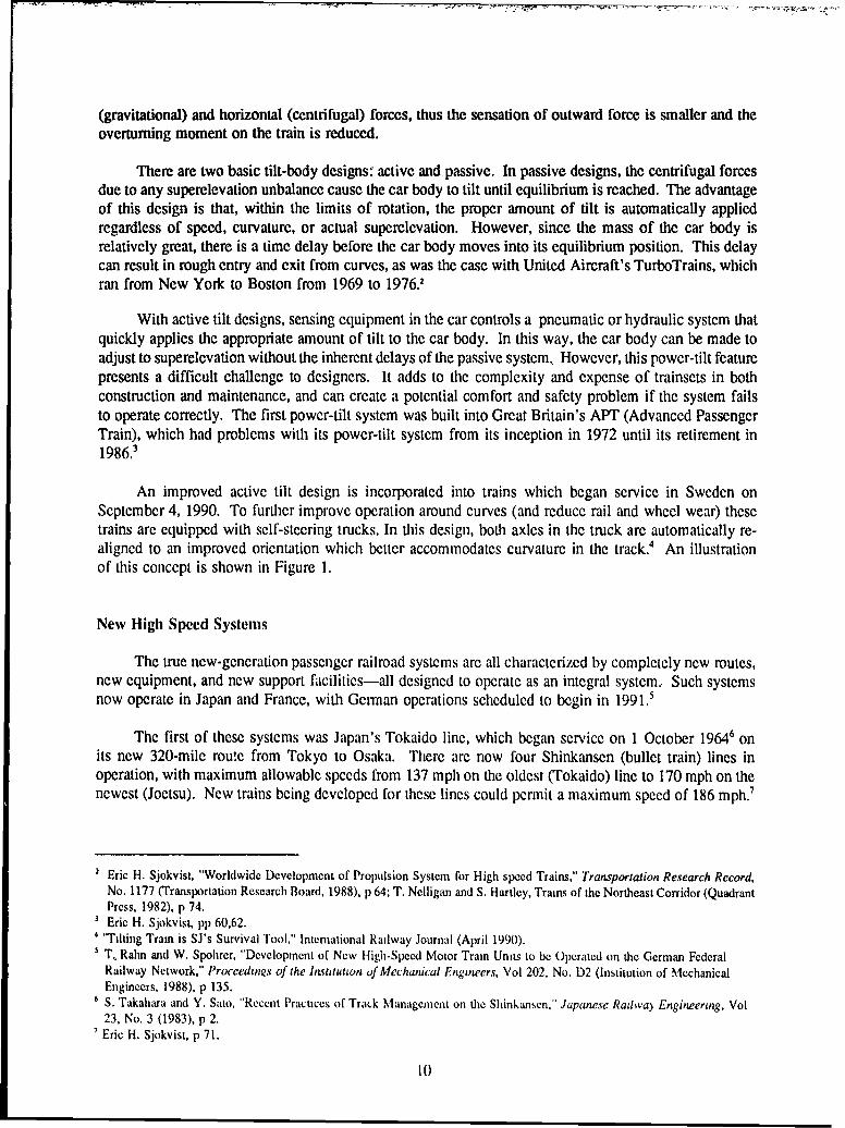
An improved active tilt design is incorporated into trains which began service in Sweden onSeptember 4, 1990. To further improve operation around curves (and reduce rail and wheel wear) thesetrains are equipped with self-steering trucks. In this design, both axles in the truck are automatically re-aligned to an improved orientation which better accommodates curvature in the track. An illustrationof this concept is shown in Figure 1.
New High Speed Systems
The true new-generation passenger railroad systems are all characterized by completely new routes,new equipment, and new support facilities-all designed to operate as an integral system.. Such systemsnow operate in Japan and France, with Genan operations scheduled to begin in 1991.5
The first of these systems was Japan's Tokaido line, which began service on 1 October 19646 onits new 320-mile routc from Tokyo to Osaka. There are now four Shinkansen (bullet train) lines inoperation, with maximum allowable speeds from 137 mph on the oldest (Tokaido) line to 170 mph on thenewest (Joetsu). New trains being developed for these lines could permit a maximum speed of 186 mph.7
2 Eric H. Sjokvist, "Worldwide Development of Propulsion System for High speed Trains," Transportation Research Record,
No. 1177 (Transportation Rcscarch Board, 1988), p 64; T. Nclligan and S. Hartlcy, Trains of the Northeast Corridor (QuadrantPress, 1982), p 74.Eric H. Sjokvist, pp 60,62."Tilting Tram is SJ's Survival Tool," International Railway Journal (April 1990).T. Rahn and W. Spohrcr, "Development of New High-Spced Motor Train Units to be Operated on the German FederalRailway Network," Proceedings of the Institution of Mechanical Engineers, Vol 202. No. D2 (Institution of MechanicalEngineers, 1988), p 135.
6 S. Takahara and Y. Sato, "Recent Practices of Track Management on the Shinkansen," Japanese Radwa) Engineering, Vol23, No. 3 (1983), p 2.Eric H. Sjokvist, p 71.
10

a. Conventional Thack
b. Steering Truck
Figure 1. Steering truck concept. (Source: High Speed Transportation: The SwedishApproach, corporate publication (Asca Brown Boveri, undated), p 8.

Currently, the fastest high speed lines ae the of the TGV (Tins I Grande Vitesse, or High SpeedTrains) in France. The Southea (SE) line began operation in 1981, with a top speed of 168 mph. TheAtlantic line, which began operation in 1989, pennits a top speed of 187 mph-*
The new German ICE (Intcr-Cty Express), scheduled to begin service in 1991, will run on acombination of new and upgraded mutes. Top speed will be 155 mph on new mutes and 125 mph onupgraded lines!
In recent years, France and Germany have been competing for the world speed record for a steelwheel-on-steel rail system. These records have been set with shortened and modified versions of highspeed equipment intended for revenue service. A summary cf this information is shown in Table 1.
Routes and Roadway
The newly constructed routes are the real key to the significantly reduced trip times possible for highspeed operations. With new routes, not only are higher maximum speeds attainable, but the percentageof route mileage on which maximum speed may be run is greatly increased. In addition, the new routesoften result in shorter mileage between end points. For example, the French TGV-SE line reduced therailroad mileage from Paris to Lyons from 318 miles to 264 milcs-a 17 percent decrease."
Table I
Worl Speed Record Data
Speed (mph) Date Country Equipment
205.6 1955 France Electric locomotive
236.4 2/26/81 France TGV Prototype - Turbine
252.9 5/1/88 Germany ICE (2 Power/3 Coaches)
299.8 12/5/89 France TGV (2 Power/4 Coaches)
317.3 5/9/90 France TGV (2 Power/3 Coaches)
317.5 5/16/90 France TGV (2 Power/3 Coaches)
320.2 5/18/90 France TGV (2 Power/3 Coaches)
Sources: "IC-Experimental Smashes the 400 Km/Hr Barrier," Railway Gazette hernational (June 1988), p 335; W.M. deRooi,"TG V-A's Record Breaking 515.3 Km/Hr," Rail Engineering International, No. 2 (1990), p 2.
G. Freeman Allen, 'TGV Atlantique-France'% Second High Speed Service," Railway Technology International (1988).9 T. Rahn and W. Spohrer, p 9.
"o A. DeTessicres, "An Introduction to the Frcnch TGV System," AREA Modcm Rail Conference in Vancouver, BC.October 1986 (AREA, 1986), 1,390
12

The mute alignments are built, for the most part, with curvature gradual enough to permit top speedoperation. The track is specially designed to accommodate the higher speeds, with concrete tiesthroughout Even the turnouts are designed for use at much higher speeds than conventional turnoutswould permit. Maintenance tolerances are tght and track and roadway inspection is intensive.
High Speed Trains
On the new high speed lines, only the trains specially designed for it are permitted to run.Propulsion is usually straight electric, with current supplied from an overhead system of power lines, orcatenary system. The locomotives (referred to as "power cars") ar high-horsepower units, ar. trains areusually run with a power car at each end. The trains are also equipped with hgh performance brakingsystems as well as advanced trouble detection and safety systems.
In Japan, the high speed trainsets are powered differently. On the original Tokaido line trains, ratherthan having power cars at each end, all axles are powered. Newer designs (Series 100) retain a similarformat; trains of 16 cars are run with 12 fully powered cars and 4 nonpowered cars." Series 300 trains(now being tested) will have 10 powered cars and 6 nonpowered cars. 2
Compared with conventional equipment, the cars for these new lines weigh less and have lighteraxle loads. The trainsets also have a smaller cross-sectional area and advanced aerodynamic shapes toreduce air resistance, which is significant at high speeds. Because the route alignments are built for highspeed, the trains have no need for the complex and potentially troublesome tilt-bod) features. Safeoperation around curves at high speeds is enhanced with state-of-the-art suspensions and a lowered centerof gravity. (Table 2 shows the center-of-gravity height for selected cars.)
Safety
The safety record of the newest and fastest high speed systems is perhaps unmatched by any othertransportation mode, including conventional railroad service. In 1989, after nearly 8 years of service ata maximum speed of 168 mph, the French TG\ -SE line celebrated carrying its 100 millionth passengerwithout any fatalities or injuries. 3 The only mishap the author is aware of involving the TGV is anincident at the Paris terminal in which, during a switching move, a TGV train (with no passengers aboard)received minor damage to its front end.
The Japanese bullet trains have had an equally enviable safety recori. From the beginning of serv-ice (in 1964) through 1982, the Tokaido line carried 2 billion passenge.s without a fatality or injury, 4
A. Mochizuki, "A New Series of the Shinkansen EMU Train Made Its Debut," Japanese Railway Engineering, No. 94(June 1985).
2 Super Hikan Will Slash Tokyo-Osaka Times," Railway Gazette International (January 1990), p 57.Scott Sullivan, "The New Supertrains," Newsweek (31 July 1989).
4 Subcommittee of High-Speed Rail Systems of the Committee on Public Transport of the Urban Transportation Division,
"High Speed Rail Systems in the United States," ASCE Journal of Transportation Engineering, Vol 111, No 2 (March1985), p 82
13
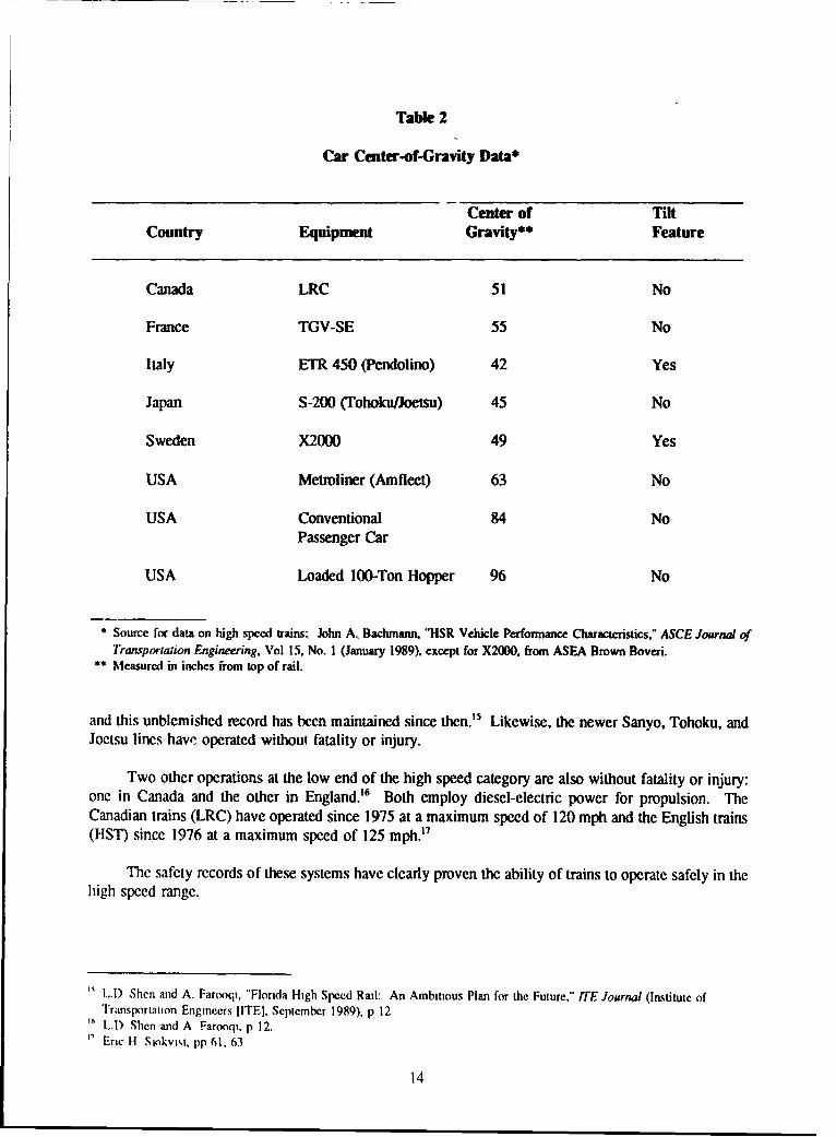
Table 2
Car Center-of-Gravity Data*
Center of TiltCountry Equipment Gravity** Feature
Canada LRC 51 No
France TGV-SE 55 No
Italy ETR 450 (Pendolino) 42 Yes
Japan S-200 (Tohoku/Joetsu) 45 No
Sweden X2000 49 Yes
USA Metroliner (Amfleet) 63 No
USA Conventional 84 NoPassenger Car
USA Loaded 100-Ton Hopper 96 No
* Source for data on high speed trains, John A, Bachmann. "HSR Vehicle Performance Characteristics." ASCE Journal of
Transporiaion Engineering, Vol 15, No. I (January 1989), except for X2000. from ASEA Brown Boveri.** Measured in inches from top of rail.
and this unblemished record has been maintained since then.'5 Likewise, the newer Sanyo, Tohoku, andJoetsu lines have operated without fatality or injury.
Two other operations at the low end of the high speed category are also without fatality or injury:one in Canada and the other in England. 6 Both employ diesel-electric power for propulsion. TheCanadian trains (LRC) have operated since 1975 at a maximum speed of 120 mph and the English trains(HST) since 1976 at a maximum speed of 125 mph. 7
The safety records of these systems have clearly proven the ability of trains to operate safely in thehigh speed range.
LI) Shen and A. Farooqi, "Florida High-Speed Rail: An Ambitious Plan for the Future." TTE Journal (Institute ofTransportation Engineers [ITE]. September 1989), p 12LI) Shen and A Farooqi, p 12.
i Eric H Siokvit, pp 61, 63
14

3 HIGH SPEED FREIGHT TRANSPORT
The use of railroad transport for mobilization implies the need to haul freight. In fact, a series oftransportation system capability studies performed by the Military Traffic Management Command(MTMC) to assess mobilization capabilities at various military installations indicates that both Army andcommercial railroads would be needed for transporting the heaviest equipment, particularly trackedvehicles such as the MI tank.
From the previous chapter, which summarizes existing high speed railroad systems, it is apparentthat today's high speed operations are intended for carrying passengers, with perhaps some provision forthe transport of small packages and express. (Two mail trains currently run on the TGV-SE line.) Thecurrent exclusion of heavy freight from high speed transport is not only based on economics, but also onthe technological obstacles to handling heavy freight at speeds over 100 mph.
The requirements for safely carrying passengers on high speed trains with high rates of accelerationpresent engineers with challenges that approach the physical limitations of conventional railroad transport.These technological challenges are even greater for carrying heavy freight at high speed.
This chapter discusses how the requirements for carrying passengers and freight differ, and thetechnological challenges that confront engineers in the design, operation, and maintenance of high speedfreight railroads.
A Difference in Weight
A comparison between a French TGV-SE train and a hypothetical tank mobilization movement canillustrate tae great differences in weights between passenger and heavy freight operations. Thisinformation is summarized in Table 3.
According to MTMC information, one flatcar designed for carrying the M1 tank weighs 47.5 tons.Adding to that its load of two M1 tanks (at 62.9 tons each) gives a total car weight of 173.3 tons. Thus,it takes about 2-1/2 loaded flatcars to equal the weight of one fully loaded TGV trainset. To make asimilar comparison based on Table 3, the MI freight weighs about the same as 20 fully loaded TGVtrains.
One alternative to reduce total train weight would be to run many short trains rather than a fewlonger ones. This has both economic and practical limitations because each train requires an engine andoperating crew, and the dramatic increase in number of trains could create traffic flow problems.
It is unlikely that new designs for high speed freight cars could result in any significant weightreductions either. Whereas the load of passengers plus baggage adds only about 10 percent to the weightof an empty lightweight passenger car, the bulk of a freight train's weight is in the load itself; the loadcapacity of a freight car is commonly about 3 times the car's empty weight, In addition, the strength tocarry this level of loading, along with the requirements to withstand dynamic forces at higher speeds overmany years' service would tend to offset any reduction in freight car weight through improved design andthe use of lighter weight materials.
15

Table 3
Weights of TGV Equipment and a Mobilization Train of M1 Tanks
TGV-SE
Empty Weight: in working order 423 tons
Load: 386 passengers + baggage 39
TOTAL 462 tons
MI Freight
Engines: three 6-axle units 540 tons
Cars:. 50 flats (140-ton) 2375
Load: 100 MI tanks 6290
TOTAL 9205 tons
Sources: Eric H. Sjokvist, p 72; G. Freeman Allen, p 74.
Clearly, freight operations result in train weights many times those typical of passenger operations.The significance of ihese differences in total train weight will become more apparent in following sections,especially those that address propulsion and braking requirements.
Power Requirements
Power requirements are dictated primarily by four factors:,
1. Train resistance
2. Maximum speed
3. Gradient and alignment of the track
4. Acceleration requirements.
The amount of power needed for a train begins with the requirement to get the train moving andkeep it moving. A relatively small amount of power is needed to move a train on level tangcnt track atlow speed. In this case, power is primarily used in overcoming the frictional resistance of wheel bearingsand the rolling resistance of the wheels on the track. This portion of train resistance has components thatare relatively constant and ones which vary directly with the speed of the train.
16

An additional compoucnt, of basic train resistance is air resistance, which varies directly with thesquare of train speed. It relates to the resistance encountered by the train moving at speed in still air (nowind).
These resistance factors lead to the basic expression for train resistance, often referred to as theDavis equation. Although modified over the years, it is still a standard in the railroad industry." Ingeneral form it can be expressed as:
R = A + Bv + Cv2 [Eq 1]
where R = resistance for a single car or engine (or train),
A, B, and C = coefficients that depend on type of equipment and operating conditions, and
v = speed of train.
Coefficients for some of the world's high speed and conventional trains are listed in Table 4.
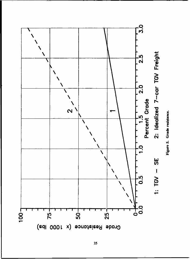
Ascending grades add a resistance of 20 lb per ton of train weight for each percentage of incline.Curves also add resistance, commonly taken as 0.8 lb per ton of train weight for each degree ofcurvature.19
Additional power is required to accelerate a train. For each ton of train weight, about 100 poundsof force is needed for each mile per hour/second of acceleration. 2° Power must also be supplied foroperating engine auxiliary equipment and, on passenger trains, for lights, air handling systems, etc. Poweris used in rotating all wheels, and a small percentage of total power is lost due to inefficiencies inherentin the engine.
Currently, all systems that provide service above the minimum level to qualify as high speed havestraight electric propulsion supplied through a catenary system. Straight electric propulsion is, in fact, arequirement for practical operation of a high speed system.2 This practical requirement is based on theamount of power needed to operate at high speed. Electric locomotives produce more power per ton oflocomotive weight than do diesel or gas turbine locomotives; stated simply, electric locomotives providemore power in about the same size package. A comparison might be made between the British dieselHST and Amtrak's electric Metroliner service. Both are intended for a top speed of 125 mph and weredesigned within 2 or 3 years of each other. One HST power car is 57.7 feet long, weighs 72 tons, andcan produce about 1950 continuous-traction horsepower.2 An Amtrak AEM-7 locomotive is 51.1 feetlong, weighs 100.1 tons, and can produce about 5500 continuous-traction horsepower. At 55 hp per tonof weight, the AEM-7 doubles the HST's output of 27 hp per ton.23
I Manual for Railway Engineering, Chapter 16 (AREA, 1989-90), p 16-2-2." Manual for Railway Engineering, p 16-2-3.20 Application of Diesel-Electric Locomotives (General Electric. Transportation Systems Division), p 9; Manual for Railway
Engineering. p 16-2-4.2' Shinya Kikuchi, High Speed Passenger Rail System: Concept, Components, and Planning (ITE, 1984), p 3-1;
Subcommittee of High-Speed Rail Systems, p 81; Eric H. Sjokvost, p 79.2 Eric H. Sjokvist, p 62.
2 ASEA Traction ABB, manufacturer's literature (1986).
17

Table 4
Train Resistance Coefficients
Total Train Equation CoefficientsCountry: Train Weight (Tons) A B C
France: TGV-SE 462 0.86 0.014 0.000367
Great Britain: 20-Car 2,000* 3.5 0.055 0.00151Freight
Great Britain: HST 409 0.64 0.0065 0.000450
Japan: 8-Car Tokaido 560* 1.23 0.025 0.000388
Japan: 12-Car Tokaido 840* 1.73 0.051 0.000573
USA: 100-Car Unit Train 14,(X)0 17 0.14 0.008(100-Ton Hoppers)
Idealized TGV-Style 1,570 2.0 0.021 0.0004777-Car Freight *
*Estimated figures
Sources: Manual for Railway Engineering, p 16-2-2; and Eric H. Sjokvist, p 58.
It should be clear that as train speeds and acceleration demands increase, so does the powerrequirement. As illustrated later in Chapter 5, supplying sufficient power---especially for high speedfreight service-presents a considerable technological challenge.
Adhesion and Tractive Effort
The force supplied by an engine to pull a train is usable only up to the limits of wheel-to-railadhesion. Force applied beyond this limit simply causes the powered wheels to spin. The amount ofadhesion depends on wheel tread, ail surface condition,, and train speed.
Adhesion is simply the coefficient of friction between the whecl tread and the rail surface, usuallyexpressed as a percentage. The highest adhesion is available at starting or low speeds on clean, dry rail.In such cases, adhesion may be as high as 30 percent. This means that propulsive force may be appliedto the rail up to an amount cqualing 30 percent ol the weight resting on the powered wheels. Adhesiondecreases if the wheel lrecd and rail are wet or covered with grease or oil. In this case, starting or low
18

o 0
0
C
0
0.
CL L
0..0I--
0. P
C
4.'
'U
UO*I64PV IOD"0
19C

speed adhesion may be only 15 percent .' Adhesion also decreases with increasing speed, as illustratedin Figure 2, which shows the relationship between adhesion and speed for both favorable and unfavorablerail surface condition.
The available propulsive force (tractive effort) depends on the power available from the engine, theamount of weight resting on the powered wheels, speed, and the coefficient of friction (adhesion) betweenthe powered wheels and the rail. Below the maximum rated value for a locomotive, tractive effort canbe approximated by the following formula:,
TE=375 xhp/v [Eq 2]
where TE = tractive effort (pounds)
hp = locomotive horsepower available for traction
v = speed (mph).
As previously noted, power demands increase with acceleration, speed, and grade. However, asspeed increases, it is clear that available propulsive force decreases due to decreasing tractive effort,increasing train resistance, and decreasing adhesion. Where tractive effort capability is beyond the limitsof adhesion, an increase in usable tractive effort may be obtained by adding weight to the engine (overthe powered wheels), but this extra weight also requires additional power to move and soon reachespractical axle load limits.
Braking and Stopping Distance
The ability to stop a train depends on its weight, speed, and available braking force. As with pro-pulsive force, for conventional braking systems, braking force is limited by wheel-to-rail adhesion. Anyforce applied to a wheel beyond this limit will cause the wheel to lock and slide along the rail.
The latest development in braking for high speed trains is the eddy current brake, which is used tosupplement conventional brakes. The system consists of a series of electromagnets which, when lowerednear the top rail surface, produce a current in the rail (an eddy current) that creates an opposing magneticfield., This produces a magnetic drag that helps stop the train., The addition of eddy current brakes to atrain adds expense in equipment and control systems, and also adds extra weight.
The German ICE trains are equipped with eddy current brakes. They are effective above 25 mphand are said to increase braking rate (deceleration) by about 40 percent, from a maximum of 1.6 mph/sec(without the eddy current brake) to 2.2 mph/sec (with the eddy current brake in use). 25 In operation,these brakes are held about 1/4 in. above the rail surface.
The control of brake!, in hleight service presents a problem not typically found in passenger service.As noted above, when an cmpty passenger car becomes completely filled with passengers, its wcightincreases by about 10 percent. When an elply ficight car is fully loaded, its weight commonly increases
2 William W. Hay, Railroad Enginecring (John Wilcy & Soii, 1982), p 1032S Klaus lcckcr-Lind rio t, "German ICE Braking,". Radli v le'ch ,l gI hi lernaional (1988)
20

by about 300 percent. Since required braking forces (to stop within a given distance) vary with a car'sweight and are limited by adhesion, effective and even braking depend on having a brake system that cansense, and adjust to, the weight of each car. This requirement complicates brake system design.
Stopping distance is proportional to the square of the speed.26 Using a constant retarding force,for example, a speed increase from 60 to 85 mph would result in doubling the stopping distance. Stoppingdistance is also proportional to the brake retarding force, which depends on the coefficient of frictionbetween the brake shoe and wheel (for standard or disc brakes) and is limited by wheel-to-rail adhesion.Both wheel-to-shoe friction and wheel-to-rail adhesion decrease with increasing speed. Retarding forceis also limited by the heat buildup due to friction in the wheel and brake shoe.
Actual stopping distance for a train must be determined by test, as braking forces vary with speed.However, when the average braking (deceleration) rate is known, approximate stopping distance can beestimated from the following formula:
SD = v2 / (7200 x BR) [Eq 3]
where SD = stopping distance in miles
v =speed in mph
BR = average braking (deceleration) ratein mph/sec.2
Using this formula, Figure 3 shows stopping distances for various average braking rates from 0.7to 2.2 mph/sec. As a mference, a average braking rate of 1.3 mph/sec is considered good brakingperformance for conventional railroad operations.
To summarize, stopping distances for high speed operation increase dramatically due to the loweredwheel-to-rail adhesion and a smaller brake shoe-wheel friction coefficient.
Grade Crossings
In his article on "High-Speed Rail Track Design," Jan H. Zicha states that "Necessary improvementsinclude the removal of at-grade crossings.. .28 The incompatibility of grade crossings on high speedlines has been well recognized. When maximum speed was raised from 100 to 130 mph in the NortheastCorridor in 1969, difficulties with grade crossings were soon apparent, and within the next several yearsall of these crossings were eliminated.
New high speed lines, such as used by the Shinkansen in Japan and the TGV in France, have beenbuilt without any grade crossings. Unlike at slower speeds, hitting a vehicle at high speed would involve
William W. Hay, p 167.,Management of Train Operation and Train Handling (Air Brake Association [ABA], 1977), p 198.
2 Jan H. Zicha, "High-Speed Rail Track Design," ASCE Journal of Transportation Engineering, Vol 115, No. 1 (January1989), p 80.
21

0~ 0-
Ln.
4)
41
vr_1:
I-
0 E
0 CD 0CC*4
(Hdri) pailddy 9JD SBOjD.Je 4oi4M jD poodS
22

such a high-energy impact (proportional to the square of the speed) that the likelihood of derailment andserious damage to a train is great. Even if no passengers were involved (e.g., a freight train or emptypassenger train) such a collision would mean almost certain serious injury or death for the train crew.Thus, as Zicha states, it is a given that high speed operation excludes grade crossings.
Dynamic Loads and Wheel/Rail Impacts
In addition to the weight of an engine or car on its wheels, there are other forces that develop asa result of motion and speed. These forces act in combination with imperfections in track geometry andwheel and rail surfaces, often taking the form of vertical impacts of the wheel on the rail. The term"dynamic load" commonly refers to the sum of these forces.
Wheel and rail surface imperfections and worn areas are a significant source of dynamic impact.
A 1/4-in, flat spot, which is considered quite small on a 40-in. diameter wheel (a common size forlocomotives in the U.S.), has been found to create a total dynamic loading factor as high as 3.0 at 125mph, and up to about 5.0 at 155 mph.29
Increased wheel loads also cause increased dynamic loading. In France, it has been observed thata 22-ton axle load at 60 mph can create the same level of dynamic loading as a 19-ton axle load movingat 170 mph.30 Thus, to keep track maintenance costs down, axle loads on TGV lines have been limitedto 18.7 tons.
Plans for the French and German railroads call for certain freight operations to begin operation at100 mph. These trains would haul specially designed, fully enclosed container cars with axle loads up toabout 19.8 tons)." (The common axle load limit in the United States is 33 tons).
High dynamic loading and its damaging effect on track have most often been associated with acombination of heavy weight and high speed. However, recent research shows that certain highervibrational frequencies generated at high speed may be of concern, even with lighte: cars.32 These higherfrequencies are said to increase ballast deterioration and subgrade settling."
Suspension Systems
The term "suspension" refers to the "resilient system through which a car body is supported on itswheels."3" Without a well designed and well tuned suspension system, train operation at high speed isnot practical. As noted in the previous section, even small wheel and track irregularities can induce largedynamic forces at high speed. These forces must be sufficiently damped to minimize wear and tear ontrack and trains, and to provide an acceptably smooth ride for passengers or freight.
Jan H. Zicha, 1989, p 70.0 Jean-Pitcre Pronost, 'Track and Structure Maintenance for 170 M.P.H. on the New Paris-Lyon TGV Line," AREA Modem
Rail Conference, Vancouver, BC. October 1986 (AREA, 1986), p 391." "Freight speed rises to 160 km/hr," Railway Gazette International (June 1990), p 455.3 B. Rajaram, "A New Theory of Rail-Wheel Interaction," Rail International, Vol 15, No. 4 (April 1984).
Jan 1i. Ziclha, 1989, pp 72, 79,' Comprehensive Radroaa Dictionary (S:.nons-Boardnan Books, Inc., 1984), p 142.
23

To function effectively, suspension designs must be matched to the weight of the vehicle. As withbraking systems, suspension designs for freight cars capable of carrying heavy freight at high speedpresent a considerable challenge to engineers. For light passenger equipment (TGV-A) the gross weightof a car may increase from 33 tons to 38 tons with the addition of passengers and luggage, or about 15percent. For freight equipment, the weight change from empty to fully loaded may be from 33 tons to133 tons-a 300 percent increase. Thus, the suspension system of a high speed freight train will have tobe effective over an extremely wide range of weights.
Derailment Consequences
When a train derails, the track, roadbed, and nearby structures become, in effect, part (or all) of thetrain's brake system; they end up absorbing the kinetic energy of the train's motion., This energy isproportional to the weight of the train and the square of its speed, and is primarily responsible for thedestruction which occurs during a derailment.
The significance of this for high speed freight operation can be seen in a comparison between aFrench TGV-SE train and a 50-car train carrying MI tanks. If both are traveling at 60 mph, the freighttrain has about 20 times the kinetic energy of the TGV. If the freight increases speed to 85 mph itskinetic energy doubles to 40 times the energy of the TGV traveling at 60 mph.
The energy of a heavy high speed train creates a potential for tremendous destruction resulting froma derailment, and offers considerable challenge to designers in creating engines and cars with sufficientstrength to withstand derailment impacts and forces. Increased strength typically implies increased weight,but, at high speeds, extra weight can significantly reduce train performance or increase power and brakerequirements. And when propelled at high speed, any increased weight adds to the potential destructiveenergy available.
24

4 ROUTE ALIGNMENT AND TRACK REQUIREMENTS
In a paper entitled "High-Speed Rail Systems in the United States" prepared by the AmericanSociety of Civil Engineers (ASCE), track requirements for the operation of high speed trains aresummarized with the statement that the track must be "built and maintained to much more demandingspecifications and closer tolerances than conventional, lower-speed tracks. 35 To illustrate howdemanding these requirements are, the paper notes that track on the French TGV-SE line is maintainedto vertical and horizontal tolerances four times stricter than allowed for Federal Railroad Administration(FRA) Class 6 track, which permits a top speed of 110 mph and is the highest speed FRA track class.
Generally, operation above 125 mph requires major changes in route alignment, track construction,and track maintenance.3" This chapter will address these requirements in more detail. The significanceof some of these requirements for high speed operation will be quantified with examples in Chapter 5.
Curves and Superelevation
One of the first considerations in operating over a route at high speed is the ability to safely andcomfortably negotiate curves. To permit satisfactory curve operation at even moderate speeds,superelevation is required: the outside rail of the curve must be raised above the elevation of the insiderail. When in perfect balance, the speed of the train and the amount of superelevation match so forcesdirected toward the outside of the curve (caused by the train's speed) equal the forces directed toward theinside of the curve (caused by gravity and superelevation). In practice, a certain amount of unbalance isallowed.
The amount of allowable unbalance depends first upon safety. At the extreme, the unbalance mustbe limited so the centrifugal forces pulling the train toward the outside of the curve, in combination witha strong wind, will not: (1) turn the train over or (2) cause a derailment by forcing the wheel flanges upover the outside rail.
In practice, superelevation limits are set by passenger comfort and maintenance considerations. Bysafety criteria alone, superelevation unbalance might allow a train to safely negotiate a curve but stillcreate centrifugal forces that knock people down in an aisle or cause coffee cups to fly across the car.And, especially with freight traffic, the high end "just safe" degree of unbalance would probably causerapid wheel and rail wear, because wheel flanges would be pushed hard against the side of the outside rail.
High amounts of superelevation, however, can result in wheel and rail wear on the inside of a curve.This is especially true when a train operates around a curve at speeds much slower than the balancingspeed. In this case, the train "falls into the curve" so gravity pulls the wheel flanges hard against theinside rail. Thus on curves with superelevation, too little speed can be as undesirable as too much.
Many studies have been conducted to determine acceptable superelevation unbalance, especially inrecent years with the emergence of high speed passenger operations., Since 1914, the standard allowable
" Subcommittee of High-Speed Rail Systems, p 81.36 Shinya Kikuchi, p 3.1,
25
unbalance in curves in he United States has been 3 in.3 This rule means that a train might, forexample, operate on a curve with 2 in. of supereicvation 3t a speed that would require 5 in. ofsuperelevation for perfect balance.
Table 5 shows the maximum curvature around which trains can comfortably operate at the listedspeeds and superelcvations. The table entries wcre determined by using the standard expression:
E = 0.0007 x D x v2 [Eq 41
where E = total (balanced + unbalanced) supcrelcvation (in.)D = degree of curve (the radius of a 1-degree curve is 5730 feet)v = speed (mph).A
In keeping with the higher unbalance sometimes allowed for the lower center-of-gravity high speedtrains,39 an unbalance of 4 in. is used as the basis for Table 5. The maximum allowable curvature isdetermined as follows:
D = (E + 4)/(0.0007 x v2) [Eq 51
where D = curvature (degrees)E = supcrclcvation (in.)v = speed (mph).
As the laws of physics dictate the requirement. for operation around curves, the allowable curvatureis inversely proportional to the square of the speed. This general rule can be seen in Table 5; theallowable curvature for operating at 120 mph, for example, is four times less than that allowed at 60 mph.The maximum curvature using standard AREA practice is shown in the column labeled 5 in. Table 6
shows the maximum degree of curvature and superclevation allowances for several high speed lines.
Referring to the columns in Table 5 for 4 in. and 7 in., and for speeds between 100 and 140 mph, itcan be seen that an increase in speed of just 20 mph around a given curve would require an extra 3 in.of superelevation. For example, at 100 mph and with 4 in. superelevation, a train can operate around a1.1 degree curve. At 120 mph, operation around the same curve would require 7 in. of superelevation.From Table 5 it is also clear that operation at the low end of the high speed range permits a maximumcurvature of about I degree. Therefore, if high speed freight trains are to support a mobilization effortthey must use routes mostly limited to curvature in this range. The implications of this limitation for highspeed service on existing track are covered in Chapter 6.
Grades
The amount of force icquired Io lift a Itain up a gade is proportional to the steepness of a grade. Thusit takes 3 times the foice to pull a train up a 3 pcicenl grade as it does a 1 percent grade.
3' F.E Dean and I) Ahlbcck, "Criteria for Ihigh-Spccd Curving of R,1l VchILcs," prccntcd to ASME Winter AnnualMeeting, December 1972 (ASME, 197)), p 2William W. Hay, p 602.
19 F E[ Dcan and I) Ahlbck, P 3
26

Table S
Maximum Allowable Curvature for DifferentSpeeds and Superelevations (at 4 in. Unbalance)
ActualSuperelevation
Speed(mph) 7 in. 6 in. S in. 4 in.
60 4.4* 4.0 3.6 3.2
80 2.5 2.2 2.0 1.8
100 1.6 1.4 1.3 1.1
120 1.1 1.0 0.9 0.8
140 0.8 0.7 0.65 0.6
150 0.7 0.65 0.55 0.5
160 0.6 0.55 0.5 0.45
180 0.5 0.45 0.4 0.35
200 0.4 0.35 0.3 0.3
*Data are expressed in degrees of curvature.
On western U.S. railroads, the ruling grades (the steepest grades of significant length) are typicallylimited to 2.2 percenL For operation in the United States, 3 percent is a common upper limit for freighttrains. The power requirements for steeper grades are considered too large for practical operation.
The TGV-SE line in France was built with grades as steep as 3.5 percent. These steep grades wereaccepted as a reasonable tradeoff for the costs saved through a reduction in number and length of bridges,a 17 percent reduction in route mileage, and the avoidance of tunnels.40 The steep grades are madeoperationally possible by taking advantage of the momentum of high speed in combination with theaerodynamic advantages of the train's reduced cross-sectional area.
4 A. DeTessieres.
27

Table 6 shows the maximum grades for several high speed lines.
Turnouts
As the general literature points out, faster speeds are only useful when they result in a significantreduction in trip time. This requires that high speed be maintained for as long a period as possible, witha minimum number of stops and speed reductions. To minimize speed reductions, it is stated that, "Thelatest design of high-speed crossovers and turnouts is critical for maintaining high-speed travel timc.""'
In conventional operations, turnouts permitting the highest speeds have typically been Number 20sin an equilateral configuration. These may allow speeds up to 70 mph-well below even the low end ofhigh speed (125 mph),
Turnouts designed for the new high speed routes are exemplified by those on the French TGV-SEline, Of 135 total turnouts, 87 are the new high speed type. These incorporate very low frog angles andmovable point frogs. There are 60 Number 46s, which allow 100 mph operation, and 27 Number 65s,which permit 140 mph.'2
Track Geometry Tolerances
Track geometry refers to the relative position of the rails:, vertically, horizontally, and of one railwith respect to the other. Especially for high speed operation, track geometry deviations must be keptsmall due to safety, track and equipment maintenance, and ride quality considerations.
As noted at the beginning of this chapter, the track geometry tolerances on the French TGV-SE lineare four times stricter than those for the highest FRA track class. On Japan's Tokaido line, where themaximum speed is 137 mph, remedial action is required when track gage becomes 1/4 in. wide and whencrosslevel deviates by 3/16 in. from design value.43 In Great Britain, the respective values for 125 mphoperation are 1/4 in. for gage, 3/16 in. for crosslevel on curves, and 1/8 in. for crosslevel on tangenttrack." Depending on the frequency generated, a defect (or defect combination) on the Tokaido line thatproduces a lateral acceleration of 0.2g calls for maintenance.4
It is clear from the literature on high speed track that such tight tolerances are necessary and havebeen successfully maintained during the operation of these lines, but at no small effort.
Maintenance
The largest maintenance activities on high speed lines include inspection for, irl correction of, trackgeometry and turnout defects. 46 Cars that measure track geometry defects and excc,,,,, accelerations (ride
Jan 1t. Z/L ha, 1989,, p 81.
Jcdn-Pierrc Pronost, p 392Jil 1 ZIhI, 1989,, p 77T ll H. d.aha. 1989, p 78S Tk ,dira alnd Y Sa O, p 1
' Ikin PICTC Pronoq,, p 393
28

TabIe 6
Route and Speed Data for Severai IO Speed Ins
Afwable SuperelevatiomSpeed Grade Curvature Actual'Unbalance
Country Operatiom (mph) (Percent) (Degrees) (Inches)
France TGV - SE 168 3.5 0.44 7.1/3.5
TGV - A 187 1. b 0.441 7.1 / 5 .1d
Germany ICE 155 1.25 0.25' 6.0/ 2.8
G. Britain HST 125 2.7 2.2 5.9 / 4.3
Italy Rome-Flmence 125 0.85 0.6 6.3 / 5.1'(Pendohno)
Japan Tokaido 137 2.0 0.7 7.1/1.2
Sanyo 143 1.5 0.44h 6.1 / 1.0
Tohoku 150 1.5 0.44 6.1 / 0.6
Joetsu 170 1.5 0.44 6.1 / 1.0
Spain 155 1.25 0.55 4.7j / 4.5
Notes
£ - Maximum speeds are not necessarily operated on the maximum grades and curves.b With a few exceptions at 2.5 percent.
- Only two curves on the line are this sharp.d 5.1 in. on the sharpest curves, otherwise 3.9 in.
0 - Service scheduled to begin during 1991; data are for newly constructed lines only.f - With a few exceptions at 0.34 degrees.. Trains have tilt-body feature.
h With a few exceptions at 0.5 degrees.'-Service planned to begin in 1992, with TGV-type trains running between Madrid and Seville.
Calculated value.
Sources: Subcommittee of High-Speed Rail Systems; Jan H. Zicha, Maglev Systems-Advantages, Risks, andUncertainties (DeLeuw, Cather, and Co., Washington, DC, 1985); Railway Gazette International (February1988 and February 1990); Japanese Railway Engineering (December 1985 and September 1986).
29

quality) are run over Japan's Tokaido line cvery 10 days47 and on Ihe French TGV-SE line everyweek." On U.S. heavy traffic freight lines, wherc whecl loads arc about 70 percent higher than thoseon the TGV and Tokaide- lincs, track geomcry cars arc commonly run about every 2 to 3 months. Out-of-face (large scale) track surfacing is carricd out cvcry 2 years on thc TGV-SE linc.49 while cvcry 3 yearsis common on U.S. heavy traffic freight lines.
The costs relatcd to maintcnancc on high spcd lincs arc discused in Chapter 6.
S '[,k lara anRd Y Sao p 6Jcan.'|l-h c P'ronotI(
e Icn-licrrc Pronos,,, p 390
3(),

5 THEORETICAL TRAIN PERFORMANCE COMPARISONS
In this chapter, some of the concepts presented in Chapters 3 and 4 will be illustrated with sewdhypothetical but realistic examples. In these examples the performances of two turainsts will be compamd.One trainset is a standard TGV-SE train, as operated in France since 1981. The other (MI Freight) is anidealized high speed freight with the general configuration of a TGV train. This MI freight train consistsof seven fully enclosed, streamlined 140-ton flatcars carrying MI tanks, plus a power car (engine) at eachend. Each power car is a hypothetical six-axle version of Amtrak's four-axle AEM-7 locomotive. (TheAEM-7 is an electric locomotive of Swedish design. It is used to haul trains in the Northeast Corridorand is currently among the best performing locomotives in the world).
As the TGV train is among the most advanced (or "ideal") passenger trains in the world, the Mlfreight train in these examples is intended to represent an advanced design with ideal performancecharacteristics. Currently, the author knows of no design concept for such a train.
An occasional comparison to current U.S. passenger and freight operations is made to supplementthe examples.
Trainset Performance Data
With a few exceptions, the performance data for the TGV-SE trainset are as given in the referencematerial. The data for the idealized seven-car M1 freight are based on a combination of existingequipment, with some additional design and performance improvement assumed."'
The freight trainset was pictured to have the same aerodynamic shape as a TGV-SE, but with a 30percent larger cross-sectional area to accommodate the flatcars and MI tanks. Power car characteristicsare based on an "improved" six-axle AEM-7. The cars are assumed to be like the current 140-ton series,but with high speed trucks, brakes, and suspension, and a lightweight streamlined shell that just clears theloaded tanks and covers the area beneath the car floor. This train would be the same length as the TGVtrain and would carry 14 MI tanks. On the outside, it would look like a taller and wider TGV with nowindows in the cars.
In developing the train resistance equation for the idealized freight, coefficients "A" and "B" weredetermined by extrapolating the Schmidt and Tuthill data5l from a 18.7-ton axle load up to a 30-ton axleload., The percentage of change in the coefficients from 18.7 to 30 tons was then figured and the resultsfrom the two data sets were averaged.. This average percentage of change was then applied to the trainresistance equation used for the TGV-SE.52 The ratio of cross-sectional areas between the idealizedfreight and the TGV-SE was used to determine coefficient "C."5'3
The tractive effort curves are based on the standard formula for tractive effort (see Adhesion andTractive Effort in Chapter 3), up to an estimated maximum output. The "short time" ratings are estimates
50 Technical Manual (TM) 55-2220-058-14, Transport of Cargo on the Radiway Flat Car (HQDA, January 1984), pp 2-1, 2-2,4-1.
51 William W. Hay, p 74.52 Eric H. Sjokvist, p 58.5 Eric H. Sjokvist, p 56.
31

of i-hour ratings for the propulsion equipment, which is an industry standard; they indicate theperformance that can be obtained for up to one continuous hour without overheating the traction motorsand other electrical propulsion cquipmcnt.
Basic data for the two example trains are listed in Table 7. Figures 4 through 8 show the resistancccurves, and continuous and short time tractive cffort are shown in Figure 9.
Examples
The first two examples address the performance requirements and capabilities of the TGV-SE andidealized Ml freight at 125 mph, A summary of the results is shown in Table 8. From this table, it isclear that both trains can easily run at 125 mph on level track. With favorable (dry) rail conditions, onlythe TGV-SE can climb a 1.5 percent grade at this speed; the Ml freight would have to reduce speed to110 mph to make this grade, With unfavorable rail conditions the TGV-SE could not maintain 125 mphon the 1.5 percent grade either. Under these conditions, the idealized M1 freight could either maintain125 mph on (at most) a 0.76 percent grade, or climb the 1.5 percent grade at about 60 mph.
Even %kith favorable rail conditions, the TGV-SE cannot accelerate at 0.3 mph/sec from 125 mph oilthe 1.5 percent grade, and the idealized MI freight falls far short of this capability.
The last example addresses the TGV-SE's performance at its top service speed of 168 mph. FromFigure 9, line 2 (short time), tractive effort at 168 mph is about 23,0(X) lb. Checking adhesion underfavorable rail conditions (Figure 2, line 1), the maximum available traction could be about 6.7 percent olthe train's total traction weight of 214 tons (Table 7), or 0.67 x 428,000 lb, which equals 28,676 lb. Thesmaller quantity-tractive effort, in this example-governs the situation, so the train's 23,000 lb isavailable. From Figure 4, line 1, the train resistance at 168 mph is about 13,5000 lb. Thu , theavailable grade-climbing force is 9500 lb (23,0(X) lb - 13,500 lb). From Figure 5, reading across from 9.-to line 1, the maximum grade the TGV-SE can climb at 168 mph is about 1.0 percent.
Summary of Examples
Especially for the idealized seven-car M1 freight, the examples show that at tile lower limit of highspeed, grade-climbing and acccleration performance are modest at best. even with no allowance for sideor head wind. At 125 mph tie M i freight, with some allowance for wind and imperfect rail condition.,could probably not handle more than about a 0.8 percent grade. 1This might suggest that tile trains ateinsufficiently powered, so a relative comparison is useful.
A common measure of relative power is the ratio of propulsion horsepower to total train weighl. usuallNc\presscd as lip/ton. As an example, a long coal train in the flat Midwest might have 1 0 to 1 l hp/Iona,,signed to it, while the faster freights (as haul-conlaincn/ed merchandise) typically have about 3 0 hp/tonThe M I freight in tihe examples above would be rated at 8.9 hp/Ion. or between 6 and 9 times what typicalficight trains currently running in the U S nomially have assigned to them
Conventional passenger trains commonly have a power level of about 5 to 6 hp/ton. The TGV-SE Itarahas 17 3 hp/ton, or 3 to 3 .5 times the power lcvel of a typical convCntion al passenger train More powcicould be added to the cxaimple i ains to impiove their pt lormance, but it should be clear that po\ er level"are already quilte high.
32

Table 7
Trainset Data for a TGV-SE Train and Idealized Seven-CarTGV-Style M1 Freight
TGV M1 Freight
Total Train Length 656 ft 656 ft
Cross Sectional Area 100 sq ft 130 sq ft
Total Loaded Weight 462 tons 1,570 tons
Total Traction Weight 214 tons 360 tons
Weight on Each Powered Wheel 17.8 k-lb 30 k-lb
Number of Powered Axles 12 12
Maximum Continuous Traction Power 8,000 hp 14,000 hp
Short Time (I Hour) Traction Power 10,000 hp* 17,000 hp
Maximum Continuous Tractive Effort 53,000 lb* 81,000 lb
Short Time (1 Hour) Tractive Effort 94,000 lb* 144,000 lb
*Estimated figures for TGV-SE.
33

0
"0
" 0~
\ -eI I--LL
k N
0
K I-O-0 0
00
N N WI
\ - -\ --
(sql 000L X) 9ouDISIS98l uIDJJ
34
'Wii
LL.
-IJ-C,
U
0 Ln
0N 2TC-(sql000 x) 3uolisa8apC,
_______ ______
'l35

r4))
4) N
cii
(sq 00 L ) --- _Ia8 a/n
F N 36

6 m149
CN,
I-
6zt2
0 0 00 0 0 co~~~~ r%- 0 Ot C4
(sql~~ ~ ~ ~ -)otx :ujis8uimaa
37.

C'
0 N
-00
F-J
~-C 00
0~~ LO 0 O
(sql ~~~~ ~0 00 )aUDSSNCuI.990
o3N

II 0N
~0
___~ __ C~
0 0
II
CL.
/ C)
I_ 0
N 00
-1.
0 0 0 E
(sqj~~~0 .OO I)404 aI3
39 .L

Table $
Propulsion Requirements and Capabilities (in Ib) ofTGV-SE and Idealized MI Freight at 125 mph
IdealizedTGV-SE MI Freight
1. Force Required:
a., Level Track 8,500 12,000
b. Up a 1.5% Grade 22,500 59,000
c. 1.5% Grade and Accelerate at 36,500 106,0M)0.3 mph/sec
2. Tractive Effort Capability 30,00) 52,000
3. Traction Limit:
a. Favorable Rail Condition (9 percent, 38,5(X) 64,800
b. Unfavorable Rail Condition (5 percent) 21,400 36,000
40

6 MOBUZATION REQUIEMENTS AND CONSTRAINTS
T chapter brey examines some mobilization requiuemnts that relate to high speed railoadtransport as it cunaely exists. These requirements would directly affect the application of high speedtrains in mobilization movements.
A National High Speed Network
For high speed trains to effectively serve during a mobilization, there must be complete routes frommobilization sites to coastal ports and other depammu points: that is, there must be a national high speedrailroad network designed with mobilization in mind.
One estimate of the minimum required mileage for a nationwide high speed freight railroad networkmight be based on the Strategic Rail Corridor Netwmk (STRACNED, as defined by the Military TrafficManagement Command. STRACNET represents a 33,000-route-mile network of railroads consideredimportant for U.S. national defense, along with about 5000 miles of important connector lines' FigRMfrom the Association of American Railroads (AAR), which represents the Class 1 railroads-the largestcarriers in the U.S.--show about 132,000 route-miles (which include about 220,000 miles of track). TheAmerican Short Line Railroad Association (ASLRA), representing the non-Class 1 roads, reports that Class2 and 3 railroads own about 30,000 m3es of track, which represents perhaps 25,000 route-miles 5' Thus,STRACNET and its connectors comprise about 24 percent of total U.S. railroad route miles (38,000 route-miles + 157,000 route-miles).
Another method for estimating the mileage requirements for a nationwide high speed railroadnetwork is to select mutes that support substantial traffic. (It might be assumed that high speed trainswould only be practical on heavy traffic lines-the more active lines of the Class 1 railroads.) A figureof 20 million gross ton-miles per year might be taken as a lower limit for heavy traffic lines. Of Class1 railroads, about 22 percent of the track (not including yard track) qualifies.5' This represents about48,400 miles (220,000 miles x 0.22).
It will be further assumed that some multiple main lines and other track would not be necessary,and that much track near urban and yard areas would not be operated at high speed. With theseassumptions, a basic high speed network of perhaps 40,000 miles might be achievable-a figure close tothe total cited for STRACNET and its important connections.
Distribution of Cars
To Rvoid the slack action (or "looseness") inherent between typical individually coupled freight cars,all high speed trains are designed as semipermancntly coupled "trainsets." While individual cars aregenerally separable, this is not usually accomplished so easily as pulling the uncoupling lever on aconventional freight car. Thus, short trainsets (which could, perhaps, be coupled together) represent themost practical configuration for high speed service.
" Civil Rail Lines Imt'ortant to National Defense (MTMC, July 1986), pp 1-7,"Railroad Facts (AAR, 1988), pp 42.43.UR.A. Abbott, "Concrete Ties vs. Wood Ties: The Debate Continues," Railway Track and Structures (March 1989).
41

Since trainsets (or carscts) typically stay together as a unit, they must be dispatched that way.Likewise, if one car in a set needs maintenance or contains a defect, the whole carset will be delayed ortaken out of service until repairs are complete.
Car Design and Loading/Unloading Operations
As both tractive effort and available adhesion decrease with increasing speed, effective high speedoperation, even on relatively level track, depends on minimizing car weight and train resistance. Aspointed out at the beginning of Chapter 3, it is unlikely that significant decreases can be made in theweight of cars intended to carry heavy equipment at high speed. Thus, the major area of potential forimproved performance is in the reduction of train resistance. Attaining such reduction, however, may makeloading and unloading operations far less convenient than with current designs.
Perhaps the primary (and fastest) method for loading and unloading heavy tracked vehicles such asMI tanks is by driving the vehicles on and off the flatcars using ramps positioned at the end of railroadspurs. The alternative is to load and unload by crane. In either operation, open flatcars with decks ofuniform height offer several logistical advantages. The uniform height ma':es driving on and off easy.The openness is also a great help in loading and unloading, especially when using a crane, and it allowsgood visibility and access during tiedown operations.
With respect to train resistance at high speed, the worst performers are cars with rough or unevensurfaces, discontinuous faces, and large cross-sectional areas-all of which describe Ml tanks riding onopen flat cars. This conventional configuration clearly is not suited to high speed operation.,
For high speed, cars require a smooth, continuous enclosure.. The importance of enclosing cars isillustrated in tests conducted on the New York Central Railroad. In these tests, the enclosure of unloaded,conventional auto-carrying cars reduced total train resistance by 37 percent at conventional freight trainspeeds.5 7
For comparison, refer again to the idealized seven-car TGYV-style MI freight used in the examplesin Chapter 5. If conventional 140-ton flat cars are substituted for the TGV-style cars (keeping the sameengines), it is estimated that train resistance would increase about 200 percent.. If unfavorable railconditions are assumed, this train could, at best, maintain 125 mph on level track with no adverse wind,There would be no reserve tractive effort to climb even a slight grade or allow for any acceleration.,
Thus, for practical high speed operation, a car carrying heavy equipment must be fully enclosed witha smooth, streamlined shape. In addition, the spaces between the cars must be similarly enclosed so thewhole train functions as a continuous aerodynamic unit.
The next most effective design improvement for reducing train resistance would be to reduce cross-sectional area. Perhaps the most realistic way of achieving this would be to design a depressed-centercar, which could possibly reduce car height by about 2 ft and cross-sectional area by about 15 to 20p'rcent. Compared to the idealized MI freight, it is estimated that at 125 mph, the use of a depressed-center car design would reduce train resistance by an additional 10 to 15 percent. This option, however,
W i Wihn W Hay, p 79
42

would probably eliminate the possibility of circus-style loading and unloading, in which the tanks are
driven up ramps and onto the flatcars.
Another design issue that would affect loading and unloading operations is the common use of
semipermanently coupled carsets in high speed service (to eliminate slack action). With cars configured
in this manner, many loading spurs, wyes, passing sidings, storage tracks, repair tracks, etc., would
probably need lengthening, or even realignment, to accommodate multiple carsets.
As indicated in Chapter 3, dynamic wheel loads are also of concern at higher speeds. If heavy
freight is to be run at 125 mph, it is not likely that the current 33-ton axle loads would be permitted; the
track deterioration rate would be extremely high. Carrying M1 tanks at this speed would probably require
each tank to be carried in a separate four-axle car, perhaps in articulated sets with steering trucks. This
arrangement would reduce axle loads to a more acceptable level of about 23 tons.
43

7 ASSESSING THE COSTS AND BENEFITS OF HIGH SPEED
Upgrading Existing Lines
Before considering the construction of new high speed lines, the feasibility of upgrading existinglines should be examined.. The use of existing lines requires, first, that the routes be suitable for highspeed service. Using the basic 40,000-mile network suggested in Chapter 6, the amount of suitableexisting mileage was assessed.
From Table 5, it is clear that high speed operations are practical on curvature of, at most, about Idegree. Table 9 lists the approximate amount of track on Class I railroads with various degrees ofcurvature. This table indicates that about 20.6 percent of Class 1 track is in curves sharper than I degree,If it is allowed that heavy traffic lines have somewhat less curvature than average, it might be estimatedthat about 15 percent of the 40,000-mile high speed freight network would contain track with curvaturesharper than I degree. If this were the case, then 6000 miles (0.15 x 40,000 miles) of the network wouldbe unsuitable for high speed operation due to its high curvature.
In practice, the percentage of track with speed restrictions due to curvature would be higher thanthe stated 15 percent, allowing for tangents before and after curves on which the trains would have to slowdown or speed up. In addition, there would be many tangents between curves too short for accelerationto high speed. Thus, perhaps 25 percent (10,000 miles) of the high speed system would be likely to havespeed restrictions due to curvature.
Certainly, much curved track within the assumed 40,0(X)-mile high speed freight network would belocated in passes through the Appalachian, Rocky, Sierra, and Cascade mountain chains, and in other areaswhere any significant realignment would be extremely expensive, even if the necessary land was available.
If high speed freight trains were similar to the idealized example in Chapter 5, then the steepest gradeon which high speed (125 mph) could be maintained (allowing for unfavorable rail conditions) is about0.8 percent. While no specific figures are presented here for the percentage of track with grades steeperthan 0.8 percent, the figure would clearly be quite substantial, especially in hilly and mountainous areas.
Thus, even from inese simple assessments, it appears that a high percentage of existing routemileage in the U.S. wo fid not be suitable for high speed trains. A quick examination of systems inoperation elsewhere ;t thk- world also indicates that practical application of high speed often requires newconstruction. The Japanese "okaido and Sanyo bullet train lines and the French TGV-SE and Atlanticlines are all new constnicti m. In addition, 267 miles of new lines are currently under construction inGermany to accommodatc the high speed service scheduled to begin operation in 1991.,"
T. Rahn and W. Spohrer.
44

Table 9
Estimated Mileage of Class I Track in Curves
Degree of Curvature Percent of Track Track Mileage
Greater Less ThanThan or Equal % Cumulative Miles Cumulative
7 --- 1.6 1.6 3,520 3,520
6 7 0.7 2.3 1,540 5,060
5 6 1.8 4.1 3,960 9,020
4 5 1.9 6.0 4,180 13,200
3 4 3.8 9.8 8,360 21,560
2 3 5.0 14.8 11,000 32,560
1 2 5.8 20.6 12,760 45,320
0 1 4.8 25.4 10,560 55,880
*Source: R.A. Abbott.
The Cost of New Construction
In a study conducted for the State of Pennsylvania, the costs for a double track, high speed routefrom Philadelphia to Pittsburgh (315 miles) were estimated (in 1986 dollars). The selected route includedboth existing mileage and new construction. For track, roadway, and earthwork only, costs ranged from$5 million to $25 million per mile.59 A 36-mile segment of new route between Altoona and StateCollege averaged $12.5 million per mile. The study also reported that costs for construction of thecomplete system (including electrification, signals, communications, etc.) averaged $22.8 million per mileover the whole route. These costs were noted as being higher than the expected national average due toPennsylvania's relatively rough terrain.
Robert E. Schnelz, "HSR Cost Estimating Techniques in Pennsylvania," ASCE Journal of Transportation Engineering,Vol 115, No. 1 (January 1989).
45

The effect of terrain is also evident in the construction costs and estimates for German high speedlines. The new 203-mile line between Hanover and Wurzburg has 39 percent of its track in tunnels, andat a conversion rate of $1 U.S. = 1.72 DM, the line's average cost per mile is about $30 million. The costof the proposed high speed line from Hanover to Berlin, which is said to run through relatively flatcountry and require no tunnels, is estimated at about $9.3 million per mile. 6
System costs for building the French high speed lines arc reported at $7.2 million per mile for thenew Atlantic line and $6.3 million per mile for the Southeast line, which began operation in 1981. 61
Estimates prepared for proposed TGV-style high speed lines in Florida give an average cost of $7 millionper mile, which is said to be low due to the state's flat terrain.62 Allowing an average cost of $12million per mile, the example 40,000 mile U.S. high speed railroad network would cost$480,000.00,000-without trains, stations, terminals, or equipment servicing facilities.
Operating Costs and Energy Consumption
System operating cGsts will, of course, vary with the level of service provided, with a primaryvariable being the number of trains run. Due to the large difference in type of service, cost esumates forhigh speed freight operation cannot be easily made from comparisons with existing high speed passengeroperations.
However, for one significant category, comparative figures are relevant: energy consumption. Forthe years 1984 through 1986, electric energy consumption accounted for about 38 percent of all directoperating expenses (including administration, but not equipment maintenance) on the French TGV-SEline.63
It is generally accepted that the required propulsive energy is nearly proportional to the square ofoperating speed.. Figure 10 shows estimated energy consumption for a EMU Metroliner train operatingbetween New York and Washington at varying maximum speeds. As the route and operations wereknown in detail, energy calculations included allowances for stops and sections where speeds would berestricted, such as through the Baltimore and New York tunnels, near terminals, curves, etc.. This resultsin total energy consumption being roughly proportional to the maximum speed to the power of 1.5.
Maintenance Costs
As the section Dynamic Loads and Wheel/Rail Impacts in Chapter 3 has already implied, trackmaintenance costs increase as operating speed increases. These increases are related to the more exactingtrack geometry requirements for high speed operation and to the greater deteriorating effects of dynamicloads at higher speeds. 64
Gerhard Pintag, "Capital Cost and Operations of High-Speed Rail System in West Germany," ASCE Journal ofTransportation Engineering, Vol 115, No. 1 (January 1989).
61 Robert E. Schmelz, p 93.62 L.D. Shen and A. Farooqi, p 14.63 Nicholas M. Brand and M. Lucas, "Operating and Maintenance Costs of the TGV High-Speed Rail System," ASCE
Journal of Transportation Engineering, Vol 115,, No 1 (January 1989).Andre Prud'Homme, "Track Problems Posed by the Running of High Speed Trains," French Railway Techn'7ues, Vol 21,No. 1 (1978).
46

A rough idea of the increased mailenancie cost due to higher speed can be obtained by examiningexpenses on the French TGV-SE line. In 1985, the TGV required about $11,000 per mile for trackmaintenance while about $7000 to $8000 was required for maintaining a mile of track on a moderate-to-heavy traffic U.S. line. While it may be argued that at least part of the higher French maintenancecosts might be attributable to public railroad ownership vs. private ownership in the United States, itshould also be noted that the SNCF (French National Railways) received no government assistance inbuilding the TGV line. The money for construction and the purchase of trainsets was supplied by SNCFand the bank loans they obtained. Likewise, SNCF is solely responsible for paying off those loans."
As noted earlier, practical high speed operation requires electrification, which in turn requires theconstruction and maintenance of a catenary system to supply power to the trains. In an estimate madefor a TGV-style operation in the U.S., catenary maintenance was given as $3300 per mile (in 1987dollars). 7
If heavy freight is to be carried at high speed, another important effect on track maintenance mustbe considered-an increase in wheel loads. As no high speed freight operations currently operate, nofigures are available for track maintenance expense increases from the combination of high speed andheavier loading. However, many years of experience with increasing wheel loads, especially in the U.S.and Canada, have clearly shown that increased wheel loading significantly increases track maintenanceexpenses.
An estimate of the wheel load effect can be made using information from a study by the IllinoisCentral Gulf Railroad on the relationship between wheel loads and track maintenance costs. While thespecific figures are for convent nal wood tie track, the indicated trend would probably apply to a varietyof track types. Referring again to the two trains from the examples in Chapter 5, the study results showabout a 35 percent increase in total track maintenance cost due to increasing wheel loads from the levelof the TGV-SE (18,700 lb) to that for the idealized Ml freight (30,000 lb)."
Beneflts: The Value of High Speed
As the literature on high speed railroad service indicates no significant operating, maintenance,energy consumption, or ecological advantages over conventional service, the dominant benefit of theseoperations appears to be in the speed itself, or in the time saved through higher speed travel. Thus, thenet benefit would be obtained by comparing the value of the time saved to the costs of establishing,operating, and maintaining a high speed railroad network.
It would appear necessary to address the following kinds of questions in assessing the value of highspeed service in mobilization activities:
I. What percentage of total transportaion time, from origin to end, does movement by railroadcurrently account for?
Jean-Pierre Pronost, p 396.
A. DeTessieres, p 390.67 Nicholas M. Brand and M. Lucas, p 46.
Robert E. Ahlf, Heavy Four-Axle Cars and Their Maintenance of Way Costs, unpublished study (Illinois Central GulfRailroad, undated).
47

0.er)
04O
-coNU
Ek
-. EA
0)0)
E ~La j
0 LO 0N C*N
(q-j uold nuo BJ
48~

2. Including loading and unloading, how much time might actually be saved if a high speed railroad
network were in place?
3. Would the time savings speed up the total mobilization effort, and if so, by how much?
4. Could significant improvements be made in the way the existing railroad system is being used?
5. How should an amount of time saved during mobilization relate to an acceptable expense forthe time savings?
Such questions, however, are beyond the scope of the present study.
49

8 CONCLUSIONS
This report has identified key issues pertaining to the application of existing conventional high speedrailroad technology to support Army mobilization. These issues are related to the characteristics ofexisting high speed systems, the technological demands implicit in using high speed railroads formobilization, route alignment and track requirements, system performance, and potential benefits versuscosts.
As mobilization plans currently appear, the use of railroad transport implies the need to haulfreight--especially heavy tracked equipment. It is important to restate that there are currently no highspeed heavy freight railroad lines in operation anywhere in the world. Neither are there indications of anysuch operations being planned for the near future,
The primary conclusion of this work is that high speed heavy freight operations present technicalchallenges of an order of magnitude beyond those for high speed passenger operations. Existing highspeed trains (and those soon to be in service) appear to be approaching the practical limits of conventionalsteel wheel-on-steel rail technology., The hauling of heavy freight at high speed would push much closerto these limits, if not exceed them.
The full potential of a high speed operation in reducing trip times is gained only when trains canrun at (or near) their maximum speed over a high percentage of the route. As both grades and curvaturewould be severely restricted for high speed freight service, these operations would be practical only oncompletely new routes, built to very high standards and maintained within very tight tolerances.
Since effective operation of high speed trains requires straight electric propulsion, with electricitysupplied through overhead wires, high speed lines would have to include a catenary and electric powerdistribution system.
For significant reduction in trip times, high speed routes must connect installations with their U.. S.mobilization destinations, which means the establishment of a national high speed network., At currentestimates this network might have an average cost of about $12 million per mile, not including the costof trains, stations, terminals, or equipment-servicing facilities.
To permit a successful high speed freight operation, locomotives would require much higherhorsepower than in existing units. Even then, trains would be quite short compared to conventional freighttrains. Also, like the high speco passenger trains now in service, high speed freight locomotives and carswould require advanced braking and suspension systems, as well as fully enclosed aerodynamic shapingto keep air resistance within practical limits, a requirement that could affect how equipment could beloaded and unloaded.
Any assessment of the net benefits of a high speed railroad operation must be made with anunderstanding of the magnitude of cost and technological challenge inherent in the construction, operation,and maintenance of these systems.
50

METRIC CONVERSION TABLE
liin. = 2.54cmIin. = 25.4 mm
I mile = 1.609 kilometers1 lb (force) = 4.45 newtonsIlb(mams) = 454grmw
I bp = 746 wattsI Ip = 0.746 kilowatts
I ton = 0.893 metric tons1 ton = 908 kilogramns
REFERENCES
Abbott, R.A., "Concrete Ties vs. Wood Ties: The Debate Continues," Railway Track & Structures (March 1989),pp 35-36.
Ahlf, Robert E., "Heavy Four-Axle Cars and Their Maintenance of Way Costs," unpublished study (Illinois CentralGulf Railroad, undated).
Allen, G. Freeman, "TGV-Atlantique--France's Second High Speed Service," Railway Technology International
(1988).
American Railway Engineering Association, Manual For Railway Engineering, Chapter 16 (1989-90).
Application of Diesel-Electric Locomotives, General Electric Transptration Systems Division.
Bachmann, John A., "HSR Vehicle Performance Characteristics," ASCE Journal of Transportation Engineering, Vol115, No. 1 (January 1989).
Becker-Lindhorst, Klaus, "German ICE Braking," Railway Technology International (1988).Brand, Nicholas M., and M. Lucas, "Operating and Maintenance Costs of the TGV High-Speed Rail System," ASCE
Journal of Transportation Engineering, Vol 115, No. 1 (January 1989).
Civil Rail Lines Important to National Defense (Military Traffic Management Command, July 1986).
Comprehensive Railroad Dictionary (Simmons-Boardman Books, Inc., 1984), P 142.
Dean, F.E., and D. Ahlbeck, "Criteria for High-Speed Curving of Rail Vehicles," presented to ASME Winter AnnualMeeting, Dec. 1972 (American Society of Mechanical Engineers, 1979).
de Rooi, W.M., "TGV-A's Record-Breaking 515.3 Km/Hr," Rail Engineering International, No. 2 (1990), p 2.
De Tessieres, A., "An Introduction to the French TGV System," AREA Modem Rail Conference in Vancouver, B.C.,October 1986 (American Railway Engineering Association, 1986).
Hay, William W., Railroad Engineering (John Wiley and Sons, 1982).
51

Headquarters, Department of the Army, "Transport of Cargo on the Railway Flat Car, 140-Ton Capacity," TM 55-
2220-058-14 (January 1984).
"IC-Experimental Smashes the 400 Km/Hr Barrier," Railway Gazette International (June 1988), p 355.
Kikuchi, Shinya, High Speed Passenger Rail System: Concept, Components and Planning (ITE, 1984).
Klauder, Louis T. Jr., "Engineering Options for the Northeast Corridor, Transportation Research Record, No. 1023(Transportation Research Board, 1985).
Management of Train Operation and Train Handling (Air Brake Association, 1977).
Mochizuki, A., "A New Series of the Shinkansen EMU Train Made Its Debut," Japanese Railway Engineering, No.94 (June 1985), pp. 6-11.
Nelligan, T., and S. Hartley, Trains of the Northeast Corridor (Quadrant Press, 1982).
Pintag, Gerhard, "Capital Cost and Operations of High-Speed Rail System in West Germany," ASCE Journal ofTransportation Engineering, Vol 115, No. 1 (January 1989).
Pronost, Jean-Pierre, "Track and Structure Maintenance for 170 M.P.H. on the New Paris-Lyon TGV Line," AREAModem Rail Conference in Vancouver, B.C., October 1986 (American Railway Engineering Association,1986).
Prud'Homme, Andre, "Track Problems Posed by the Running of High Speed Trains," French Railway Techniques,Vol 21, No. 1 (1978).
Rahn, T., and W.. Spohrer, "Development of New High-Speed Motor Train Units to be Operated on the GermanFederal Railway Network," Proceedings of the Institution of Mechanical Engineers, Vol 202, No. D2(Institution of Mechanical Engineers, 1988).
Railroad Facts, Association of American Railroads, 1988.
Rajaram, B., "A New Theory of Rail-Wheel Interaction," Rail International, Vol 15, No. 4 (April, 1984).
Schmelz, Robert E., "HSR Cost Estimating Techniques in Pennsylvania," ASCE Journal of Transpov'ationEngineering, Vol 115, No. 1 (January 1989).
Shen, L. D., and A. Farooqi, "Florida High-Speed Rail: An Ambitious Plan for the Future," I T E Journal (I'1.ttuteof Transportation Engineers, September 1989).
Sjokvist, Eric H., "Worldwide Development of Propulsion System for High Speed Trains," Transportation Research
Record, No. 1177 (Transportation Research Board, 1988).
"Spain's Fastest Trains to Roll in 1992," Railway Gazette International (February 1990), pp 129-131..
"Spain Launched on High Speed Quest," Railway Gazette International (February 1988), pp 101-103.
Subcommittee of High-Speed Rail Systems of the Committee on Public Transport of the Urban TransportationDivision, "High Speed Rail Systems in the United States," ASCE Journal of Transportation Engineering, Vol111, No. 2 (March 1985).
52

Suda, C., "Toward the Realization of 270 Km/Hr Operation," Japanese Railway Engineering, No. 96 (December
1985), pp 2-7.
Suda, C., "Train Speedup and Track Structure," Japanese Railway Engineering, No. 99 (September 1986), pp 2-12.
Sullivan, Scott, "The New Supenrains," Newsweek, (July 31 1989), pp 46-48.
"Super Hikari Will Slash Tokyo-Osaka Times," Railway Gazette International (January 1990), p 57.
Takahara, S., and Sato, Y., "Recent Practices of Track Management on the Shinkansen," Japanese RailwayEngineering, Vol 23, No. 3, (1983).
"Tilting Train is SJ's Survival Tool," International Railway Journal (April 1990).
Wayson, RI.., and W. Bowlby, "Noise and Air Pollution of High Speed Rail Systems," ASCE Journal ofTransportation Engineering, Vol 115, No. 1 (January 1989).
Zicha, Jan H., "High-Speed Rail Track Design," ASCE Journal of Transportation Engineering, Vol 115, No. 1(January, 1989).
Zicha, Jan H., Maglev Systems: Advantages, Risks, and Uncertainties (DeLeuw, Cather, and Company, Washington,D.C., 1985).
53

ABBREVIATIONS
AAR American Association of Railroads
APT Advanced Passenger Train
AREA American Railway Engineering Association
ASCE American Society of Civil Engineers
ASLRA American Short Line Railroad Association
FRA Federal Railroad Administration
HST High-Speed Train
ITE Institute of Transportztion Engineers
LRC Light-Rapid-Comfortable
MTMC Military Traffic Management Command
SNCF French National Railways
STRACNET Strategic Rail Cornidor Network
TGV Train A Grande Vitesse
TGV-SE TGV, Southeast line
54

USACERL DISTRIBUTION
(md ar hsms FORcSOATIR: CFM H C) FORSCOMlEn r.ATrN: SF Do 15071ATTN: CERBC-IM-P (2) ATTN- Fadiim EngbwATTN- CZe Fat bn 230ATTIR- CEIP-C Fat C1mbeU 42 3ATTN: CMP-E Pt Cmm 30913ATTN: nD out mm 01433ATTRN: IMD-L Fut Dam 13601ATIN. CERD-C Fort Elood 7644ATTN: I ED-M Fot lwin 92310ATIN: DAEN-_C Put Lwis 91433ATTN: CEMPEr (5) Fat Cl 93941
Fat Fhk 71459CEHSC 2060 Fot Sanwt 31314
ATTN: CEHSC-FTRADOC (11)
US Amy Eme Disic HQ. TRADOC, ATT: ATER-DER 23651ATN. Lilua ATTN: DER
Bahimore 21203 Fat elvair 22060Fot Woth 76102 Fort Bunting 31905L l 40201 Fct Bliss 79916Mobile 36623 Fat Chaffoc 72905NIhlk 202 F, Ft Eumis 23604Naoo 23510 Fort Knox 40121Omaha 63102 Fat Lmonsidwood 65473Portland 923Rock almd 6124 SHAPE 090Sacammo 95814 ATTN: Jifraaucumze Bnd LANDA
US Army Eng Division HQ USEUCOM 09128ATTN: Librry ATTN: BCI 4fl-LOE
Huntsville 35807Loww Nssisippi Valley 39130 Fort Bdivr. VA 22060MlsaauiRiver 68101 ATTN: Avtmailian Liaison Officer
ATTN: CEMRD-EP-Tr (3) ATrN: Engr Stldie CenerNorth Atlantic 10007North Ctral 60605 CECRL, ATrN: Libary 03755North Pacfic 97203
ATTN: CENPD-EN-G Tyndall AFB, FL 3403Ohio River 45201 AFESCMngineing & Sevice LabSouth Atlantic 30335South Pacific 94111 NAVFAC
ATIN: CESAD-EN-O Southen Division 29411Southwtrn ATTN: Facilities Engr Cmd
Alxandria, VACEWESATrN: library 39130 Code 03 22332
ATITN: Naval Public Wods CenerPt. Leoneat Wood, MO 65473 Norfolk 23511
ATTN: Canadian Lam Officar Seattle 93762ATTN: Omman Liaison Staff ATTN: Naval Civil Engr Lab 93043 (3)ATTN: Brtich Laion, Officar (2)ATrN: Frenh Liaison Officar Enginering SociMies Library
New Yok, NY 10017416th Enginee Command
ATTN: Faciliti Enginee National Guard lureau 20310ILmallation Division
US Mihtary Acadany 10996ATTN: Facihtm Engineer US Govamnont Printing Office 20401
Receiving Depoitory Secuon (2)DLA ATTN- DLA-WI 22304
Nat'l Institute of Standads & Tech 20899DNA ATrN" NADS 20305
Defsoia Tochmcal Info Caner 22304Mihtary Traffic Mgrnt Command ATTN: DTIC-FAB (2)
Falls Church 20315Oakland Army Base 94626Baynne 07002Sunny Pont MOT 28461 94
Q/90