LIPI VIIA Marisel jimenez Pedagogía Infantil Diana Ferley Vargas.
REMOVE
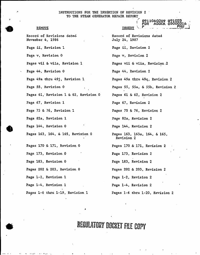
INSTRUCTIONS FOR THE INSERTION OF REVISION 2TO THE STEAM GENERATOR REPAIR REPORT
S9110b02b9 891025PDR ADOCK 050003ib
~NSERT
Record of Revisions datedNovember 4, 1986
Page ii, Revision 1
Page v, Revision 0
Pages vii & viia, Revision 1
Page 44, Revision 0
Page 49a thru 49j, Revision 1
Page 55, Revision 0
Pages 61, Revision 1 & 62, Revision 0
Page 67, Revision 1
Page 75 & 76, Revision 1
Page 82a, Revision 1
Page 144, Revision 0
Pages 163, 164, & 165, Revision 0
Pages 170 & 171, Revision 0
Page 173, Revision 0
Page 183, Revision 0
Pages 202 & 203, Revision 0
Page 1-2, Revision 1
Page 1-4, Revision 1
Pages 1-6 thru 1-19, Revision 1I
Record of Revisiqns datedJuly 24, 1987
Page ii, Revision 2
Page v, Revision 2
Pages vii & viia, Revision .2
Page 44, Revision 2
Pages 49a thru 49q, Revision 2
Pages 55, 55a, & 55b, Revision 2
Pages 61 & 62, Revision 2
Page 67, Revision 2
Pages 75 & 76, Revision 2
Page 82a, Revision 2
Page 144, Revision 2
Pages 163, 163a, 164, & 165,Revision 2
Pages 170 & 171, Revision 2
Page 173, Revision 2
Page 183, Revision 2
Pages 202 & 203, Revision 2
Page 1-2, Revision 2
Page 1-4, Revision 2
Pages 1-6 thru 1-20, Revision 2

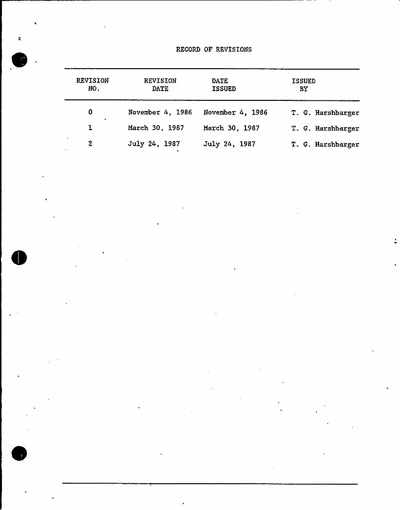
RECORD OF REVISIONS
REVISIONNO.
REVISIONDATE
DATEISSUED
ISSUEDBY
March 30, 1987
July 24, 1987
March 30, 1987
July 24, 1987
November 4, 1986 November 4, 1986 T. G. Harshbarger
T. G. Harshbarger
T. G. Harshbarger
Section ~Pa e
2.2.2
2.2.3
2.3
Parametric Comparison
Materials Comparison
Component Design Improvements
28
28
32
2.3.1 Design Improvements to MinimizePotential for Tube Degradation 32
2.3.2 Design Improvements to Increase Performance 37
2.3.3 Design Improvements to Enhance Maintainabilityand Reliability 38
2.4
2.4.1
2 '.22.5
Codes and Standards
Industry Codes and Standards
USNRC Regulatory Guides
Shop Tests and Inspections
40
40
40b
42
3.1
3.2
3.3
3.3.1
3.3.2
3.3.3
3.3.4
3.4
3.4.1
SECTION 3 - REPAIR PROJECT
Overview
Guidelines and Criteria
Preshutdown Activities
Site Preparation
Shipment and Storage of Replacement Components
Modification to Auxiliary Building Structural Steel
Polar Crane Power Circuit Relocation
Post Shutdown Activities
Containment Preparations
47
50
50
55
55a
55a
55a
3.4.2 Removal of Concrete, Structural and EquipmentInterferences 57
3.5 Steam Generator Removal Activities 62
3.5.1 Steam Generator Cutting Methods and Locations 62
3.5.2 Removal and Handling of the Steam GeneratorUpper Assemblies 64
3.5.3 Removal and Handling of the Steam GeneratorLower Assemblies 66
Revision 2
~Sectic ~Pa e
6.2.1
6.2.2I
6.3
6.4
6.4.1
6.4.2
6.4.3
Handling of Heavy Loads
Shared System Analysis
Fire Protection Evaluation
Analysis of Significant Hazards
Criterion 1
Criterion 2
Criterion 3
155
162
163
163a
164
164
165
SECTION 7 - ENVIRONMENTAL REPORT
7.1
7.2
. 7.2.1
7.2.2
Purpose of the Environmental Report
The Plant and Environmental Interfaces
Geography and Demography
Regional Historic, Archaeological, Architectural,Scenic, Cultural, and Natural Features
166
166
166
167
7.2.'3
7.2.4
7 ' '
7.2.6
Hydrology
Geology
Ecology
Noise
167
168
168
169
7.3
7.3.1
7.3.2
Non-Radiological Environmental Effects
Geography and Demography
Regional Historic, Archaeological, Architectural,Scenic, Cultural, and Natural Features
169
169
170
7.3.3
7.3.4
7.3.5
7.3.6
7.4.1
Hydrology
Geology
,Ecology
Noise
Radiological Environmental Effects
Occupational Exposure
170
171
171
172
172
172
Revision 2
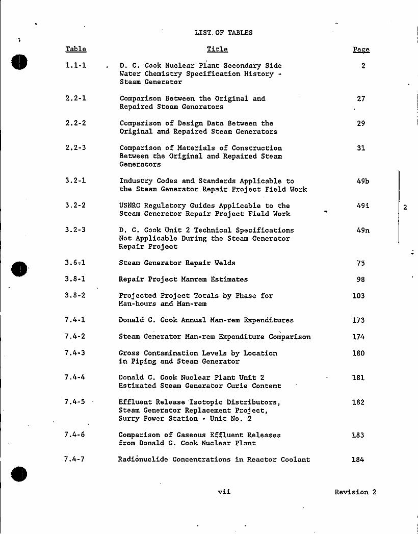
LIST OF TABLES
Table
1.1-1
Title
D. C. Cook Nuclear Plant Secondary SideWater Chemistry Specification History-Steam Generator
~Pa e
2.2-1 Comparison Between the Original andRepaired Steam Generators
27
212-2 Comparison of Design Data Between theOriginal and Repaired Steam Generators
29
202-3 Comparison of Materials of ConstructionBetween the Original and Repaired SteamGenerators
31
3.2-1 Industry Codes and Standards Applicable tothe Steam Generator Repair Project Field Work
49b
3.2-2 USNRC Regulatory Guides Applicable to theSteam Generator Repair Project Field Work
49i
3.2-3 D. C. Cook Unit 2 Technical SpecificationsNot Applicable During the Steam GeneratorRepair Project
49n
3. 6-.1
3 '-1Steam Generator Repair Welds
Repair Project Manrem Estimates
75
98
3,8-2 Projected Project Totals by Phase forMan-hours and Man»rem
103
7.4-1
7.4-2
7.4-3
Donald C. Cook Annual Man-rem Expenditures
Steam Generator Man-rem Expenditure Comparison
Gross Contamination Levels by Locationin Piping and Steam Generator
173
174
180
7.4-4 Donald C. Cook Nuclear Plant Unit 2Estimated Steam Generator Curie Content
181
7.4-5 Effluent Release Isotopic Distributors,Steam Generator Replacement Project,Surry Power Station - Unit No. 2
182
7.4-6 Comparison of Gaseous Effluent Releasesfrom Donald C. Cook Nuclear Plant
183
7.4-7 Radionuclide Concentrations in Reactor Coolant 184
vii Revision 2
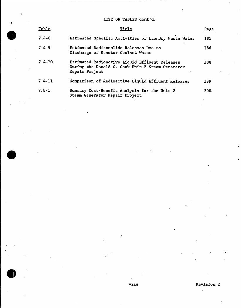
LIST OF TABLES cont'd.
Table
7.4-8
7.4-9
Title ~Pa e
Estimated Radionuclide Releases Due toDischarge of Reactor Coolant Water
186
Estimated Specific Activities of Laundry Waste Water 185
7.4-10
7.4-11
Estimated Radioactive Liquid Effluent ReleasesDuring the Donald C. Cook Unit 2 Steam GeneratorRepair Project
Comparison of Radioactive Liquid Effluent Releases
188
189
Summary Cost-Benefit Analysis for the Unit 2Steam Generator Repair Project
200.
viia Revision 2

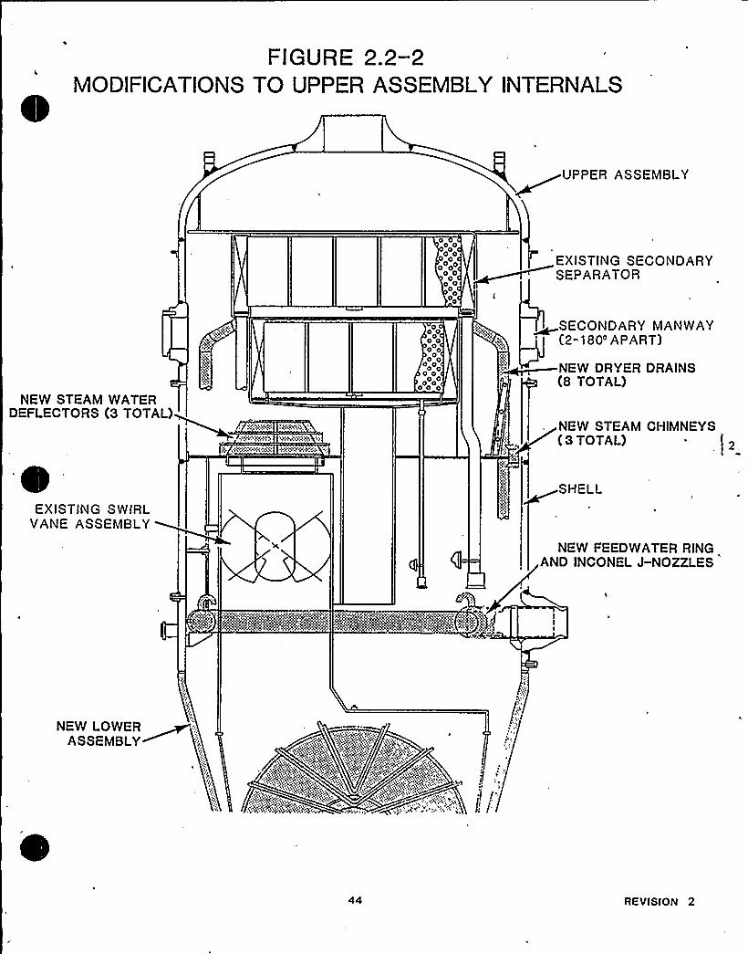
FIGURE 2.2-2MODIFICATIONS TO UPPER ASSEMBLY INTERNALS
UPPER ASSEMBLY
NEW STEAM WATERDEFLECTORS (3 TOTAL)
iciwNXcc/0 +5N+C(l..b
00 00 0
0 00 00
0 00
4oo44
40
0 00 00 00
0 0
0 40 000 0
EXISTING SECONDARYSEPARATOR
~SECONDARY MANWAY(2" 180'PART)
~NEW DRYER DRAINS(8 TOTAL)
NEW STEAM CHIMNEYS{3 TOTAL)
EXISTING SWIRLVANE ASSEMBLY
SHELL
NEW FEEDWATER RINGAND INCONEL J-NOZZLES
"ltd~:%i:i)g4%~%MA>s
NEW LOWERASSEMBLY
44 RE VISION 2
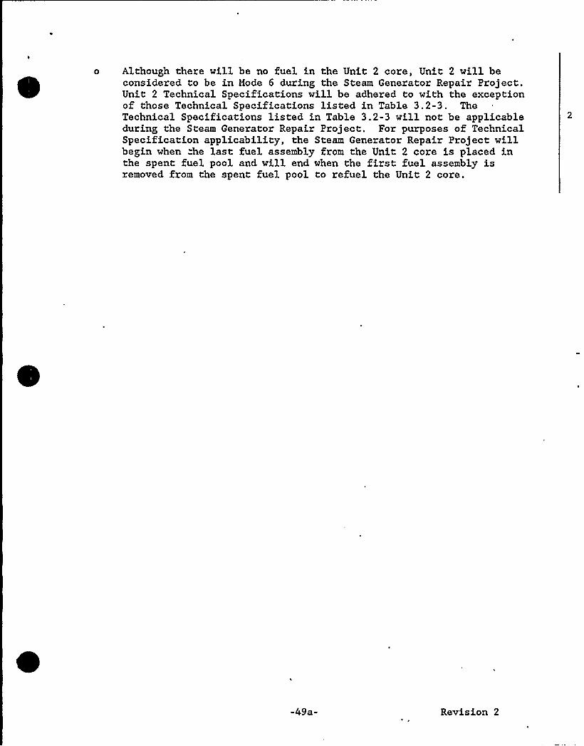
o Although there will be no fuel in the Unit 2 core, Unit 2 will beconsidered to be in Mode 6 during the Steam Generator Repair Project.Unit 2 Technical Specifications will be adhered to with the exceptionof those Technical Specifications listed in Table 3.2-3. TheTechnical Specifications listed in Table 3.2-3 will not be applicableduring the Steam Generator Repair Project. For purposes of TechnicalSpecification applicability, the Steam Generator Repair Project willbegin when "he last fuel assembly from the Unit 2 core is placed inthe spent fuel pool and will end when the first fuel assembly isremoved from the spent fuel pool to refuel the Unit 2 core.
-49a- Revision 2
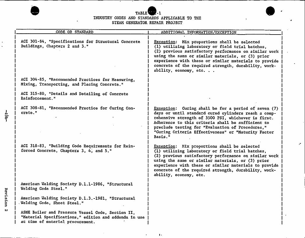
TABLE -1INDUSTRY CODES AND STANDARDS APPLICABLE TO THE
STEAM GENERATOR REPAIR PROJECT
CODE OR STANDARD
ACI 301-84, "Specifications for Structural ConcreteBuildings, Chapters 2 and 3."
ACI 304-85, "Recommended Practices for Measuring,Mixing, Transporting, and Placing Concrete."
ACI 315-80, "Details and Detailing of ConcreteReinforcement."
ACI 308-81, "Recommended Practice for Curing Con-crete."
ACI 318-83, "Building Code Requirements for Rein-forced Concrete, Chapters 3, 4, and 5."
American Welding Society D.l.1-1986, "StructuralWelding Code Steel."
American Welding Society D.l.3.-1981, "Structural. Welding Code, Sheet Steel."
ASME Boiler and Pressure Vessel Code, Section II,"Material Specifications," edition and addenda in useat time of material procurement.
ADDITIONAL INFORMATION EXCEPTION
I~Exec tion: Mix proportions shall be selected(1) utilizing laboratory or field trial batches,(2) previous satisfactory performance on similar workusing the same or similar materials, or (3) priorexperience with these or similar materials to provideconcrete of the required strength, durability, work-ability, economy, etc.
I
I
I
I
I
I
I
~Exec tion: Curing shall be for a period of seven (7)days or until standard cured cylinders reach a comp-rehensive strength of 3500 PSI, whichever is first.Adherence to this criteria shall be sufficient topreclude testing for "Evaluation of Procedures,""Curing Criteria Effectiveness" or "Maturity FactorBasis."
I~Exec tibn: Mix proportions shall be selected(1) utilizing laboratory or field trial batches,(2) previous satisfactory performance on similar workusing the same or similar materials, or (3) priorexperience with these or similar materials to provideconcrete of the required strength, durability, work-ability, economy, etc.
I
I
I
I
I
I
I
I
I
I
I
I
I
I
I
I
I
I
I
I
I
I
I
I
I
I
I
I
I
I
I
I
I
I
I
I
I
I
I
I
I
I
I
I
I
I
I
I.I
I

TABLE 3.2- ontinued)
CODE OR STANDARD
ASME Boiler and Pressure Vessel Code, Section III,"Rules for Construction of Nuclear Vessels/Rules forConstruction of Nuclear Power Plant Components,"edition and addenda as discussed below.
The original Construction code for D. C. CookUnit 2 nuclear vessels is Section III, 1968Edition plus Addenda through Winter 1968, and forpiping components is ANSI B31.1-1967 and ANSIB31.7-1969.
As allowed by ASME Section XI, SubarticleIWA-7210, selected portions of the originalConstruction Codes dealing with installation andtesting will be updated to applicable portions ofSection III, 1983 Edition plus Addenda throughSummer 1984.
ASME Boiler and Pressure Vessel Code, Section IX,"Welding and Brazing Qualifications," edition andaddenda in use at time of procedure qualification.
ASME Boiler and Pressure Vessel Code, Section XI,"Rules for Inservice Inspection of Nuclear PowerPlant Components," 1983 Edition plus Addenda throughSummer 1983.
ANSI B31.1, "Power Piping", edition and addenda inuse at time of contract award for field pipingservices.
ANSI N45.2 - 1977 Quality Assurance Program,'Requirements for Nuclear Facilities
USAS (ANSI) B31.1-1967, "Power Piping".USAS (ANSI) B31.7-1969, "Nuclear Power Piping".
I
I
I
I
I
I
I
I
I
I
I
I
I
I
I
I
I
I
I
I
I
I
I
I
I
I
I
I
I
I
I
I
I
I
I
I
I
I
I
I
ADDITIONALINFORMATION EXCEPTION
Exce tions: - Consistent with the plant design basis,fracture toughness requirements will not apply.
- N-stamping of fabricated piping componentswill not be required.
~Exec tion: - Consistent with the plant design basis,fracture toughness requirements will not apply.
~Exec tion: - As noted under ASME Boiler and PressureVessel Code, Section III, "Rules for Constructionof Nuclear Vessels/Rules for Construction ofNuclear Power Plant Components" above, these codesrepresent the original Construction Code for
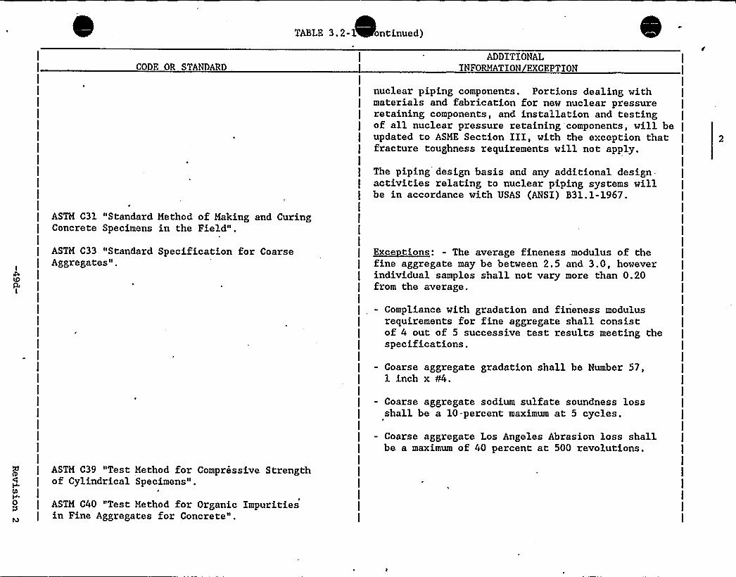
TABLE 3.2-1 ontinued)
CODE OR STANDARDADDITIONAL
INFORMATION EXCEPTION
nuclear piping components. Portions dealing withmaterials and fabrication for new nuclear pressureretaining components, and installation and testingof all nuclear pressure retaining components, will beupdated to ASME Section III, with the exception thatfracture toughness requirements will not apply.
The piping design basis and any additional design.activities relating to nuclear piping systems willbe in accordance with USAS (ANSI) B31.1-1967.
ASTM C31 "Standard Method of Making and CuringConcrete Specimens in the Field".
ASTM C33 "Standard Specification for CoarseAggregates".
~Exec tions: - The average fineness modulus of thefine aggregate may be between 2.5 and 3.0, howeverindividual samples shall not vary more than 0.20from the average.
Compliance with gradation and fineness modulusrequirements for fine aggregate shall consistof 4 out of 5 successive test results meeting thespecifications.
Coarse aggregate gradation shall be Number 57,1 inch x C4.
Coarse aggregate sodium sulfate soundness lossshall be a 10-percent maximum at 5 cycles.
Coarse aggregate Los Angeles Abrasion loss shallbe a maximum of 40 percent at 500 revolutions.
ASTM C39 "Test Method for Compressive Strengthof Cylindrical Specimens".
ASTM C40 "Test Method for Organic Impuritiesin Fine Aggregates for Concrete".
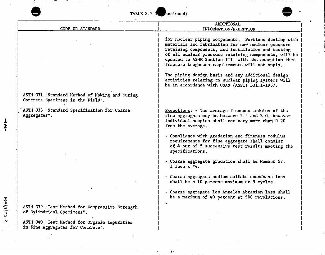
TABLE 3.2- ontinued)
CODE OR STANDARDADDITIONAL
INFORMATION EXCEPTION
ASTM C31 "Standard Method of Making and CuringConcrete Specimens in the Field".
I
ASTM C33 "Standard Specification for CoarseAggregates".
for nuclear piping components. Portions dealing withmaterials and fabrication for new nuclear pressureretaining components, and installation and testingof all nuclear pressure retaining components, will beupdated to ASME Section III, with the exception thatfracture toughness requirements will not apply.
The piping design basis and any additional designactivities relating to nuclear piping systems willbe in accordance with USAS (ANSI) B31.1-1967.
Exce tions: - The average fineness modulus of thefine aggregate may be between 2.5 and 3.0, howeverindividual samples shall not vary more than 0.20from the average.
- Compliance with gradation and fineness modulusrequirements for fine aggregate shall consistof 4 out of 5 successive test results meeting thespecifications.
- Coarse aggregate gradation shall be Number 57,1 inch x W.
- Coarse aggregate sodium sulfate soundness lossshall be a 10 percent maximum at 5 cycles.
- Coarse aggregate Los Angeles Abrasion loss shallbe a maximum of 40 percent at 500 revolutions.
ASTM C39 "Test Method for Compressive Strengthof Cylindrical Specimens",
ASTM C40 "Test Method for Organic Impuritiesin Fine Aggregates for Concrete".

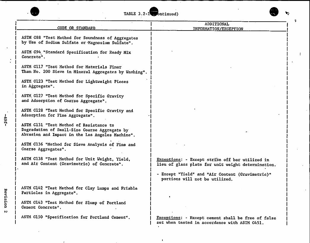
TABLE 3.2-1 ntinued)
CODE OR STANDARDADDITIONAL
INFORMATION EXCEPTION
ASTM C88 "Test Method for Soundness of Aggregatesby Use of Sodium Sulfate or Magnesium Sulfate".
ASTM C94 "Standard Specification for Ready MixConcrete".
ASTM C117 "Test Method for Materials FinerThan No. 200 Sieve in Mineral Aggregates by Washing".
ASTM C123 "Test Method for Lightweight Piecesin Aggregate".
ASTM C127 "Test Method for Specific Gravityand Adsorption of Coarse Aggregate".
ASTM C128 "Test Method for Specific Gravity andAdsorption for Fine Aggregate".
ASTM C131 "Test Method of Resistance toDegradation of Small-Size Coarse Aggregate byAbrasion and Impact in the Los Angeles Machine".
ASTM C136 "Method for Sieve Analysis of Fine andCoarse Aggregates".
ASTM C138 "Test Method for Unit Weight, Yield,and Air Content (Gravimetric) of Concrete".
Exce tions: - Except strike off bar utilized inlieu of glass plate for unit weight determination.
- Except "Yield" and "Air Content (Gravimetric)"portions will not be utilized.
ASTM C142 "Test Method for Clay Lumps and FriableParticles in Aggregate" ~
ASTM C143 "Test Method for Slump -of PortlandCement Concrete".
ASTM C150 "Specification for Portland Cement". ~Exec c1ons: - Except cement shall be free of falseset when tested in accordance with ASTM C451.
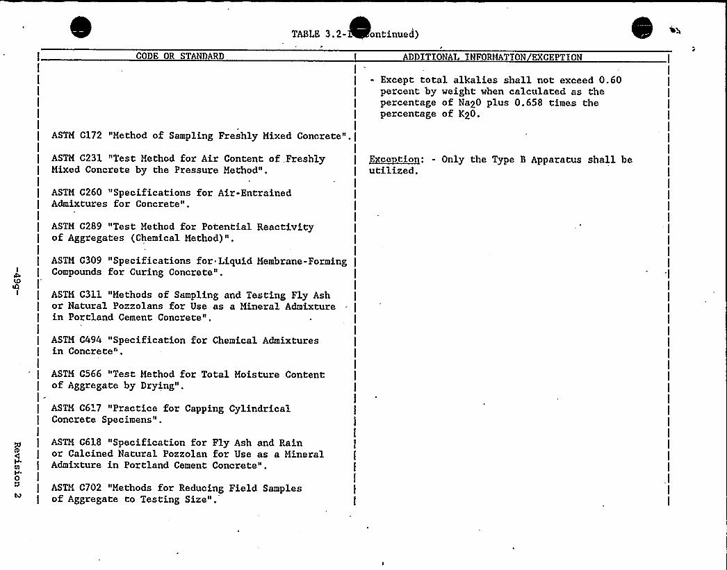
TABLE 3.2- ontinued)
CODE OR STANDARD
I
I
I
I
I
ADDITIONAL INFOMfATION EXCEPTION
- Except total alkalies shall not exceed 0.60percent by weight when calculated as thepercentage of Na20 plus 0.658 times thepercentage of K20.
IASTM C172 "Method of Sampling Freshly Mixed Concrete".[
ASTM C231 "Test Method for Air Content of,FreshlyMixed Concrete by the Pressure Method".
ASTM C260 "Specifications for Air-EntrainedAdmixtures for Concrete".
ASTM C289 "Test Method for Potential Reactivityof Aggregates (Chemical Method)".
~Exec tice: - Only the Type 3 Apparatus shall beutilized.
ASTM C309 "Specifications for Liquid Membrane-FormingCompounds for Curing Concrete".
ASTM C311 "Methods of Sampling and Testing Fly Ashor Natural Pozzolans for Use as a Mineral Admixturein Portland Cement Concrete".
ASTM C494 "Specification for Chemical Admixturesin Concrete".
ASTM C566 "Test Method for Total Moisture Contentof Aggregate by Drying".
I=ASTM C6'7 "Practice for Capping CylindricalConcrete Specimens".
ASTM C618 "Specification for Fly Ash and Rainor Calcined Natural Pozzolan for Use as a MineralAdmixture in Portland Cement Concrete".
ASTM C702 "Methods for Reducing Field Samplesof Aggregate to Testing Size".
I
I
I=
I
I
I
I
I
I
I
I
I
I
I
I
I
I
I
I
I
I
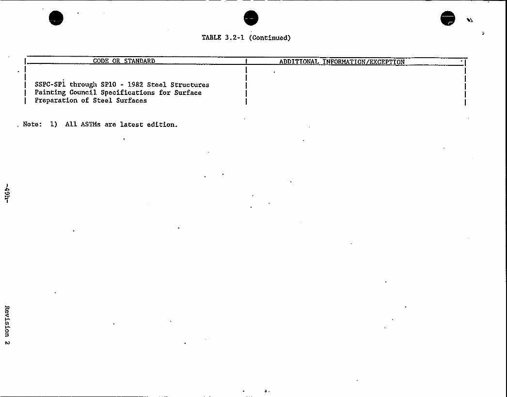
TABLE 3.2-1 (Continued)
CODE OR STANDARD ADDITIONAL INFORMATION EXCEPTION
I
SSPC-SP1 through SP10 - 1982 Steel StructuresPainting Council Specifications for SurfacePreparation of Steel Surfaces
Note: 1) All ASTMs are latest edition.
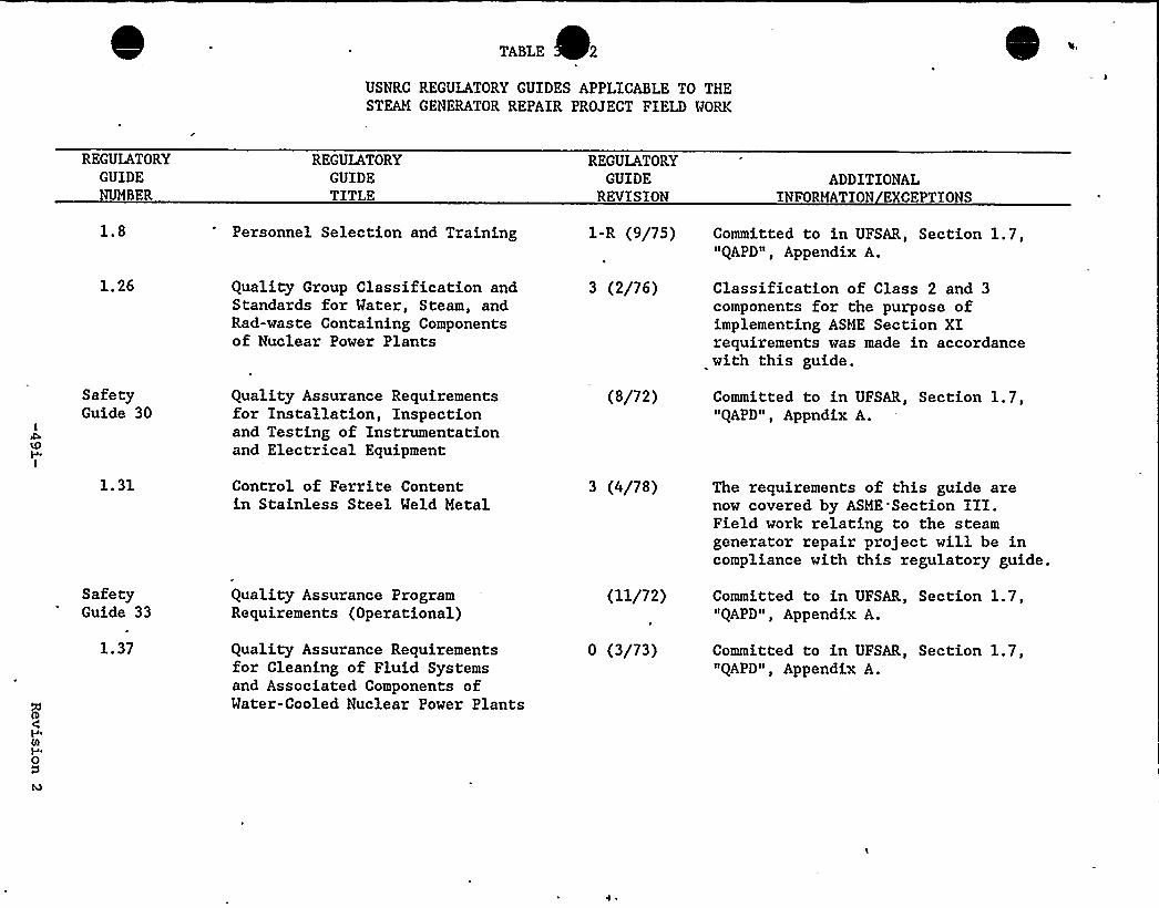
TABLE 2
USNRC REGULATORY GUIDES APPLICABLE TO THESTEAM GENERATOR REPAIR PROJECT FIELD WORK
REGULATORYGUIDENUMBER
REGULATORYGUIDETITLE
REGULATORYGUIDE
REVISIONADDITIONAL
INFORMATION EXCEPTIONS
1.8 Personnel Selection and Training 1-R (9/75) Committed to in UFSAR, Section 1.7,"QAPD", Appendix A.
1.26
SafetyGuide 30
Quality Group Classification andStandards for Water, Steam, andRad-waste Containing Componentsof Nuclear Power Plants
Quality Assurance Requirementsfor Installation, Inspectionand Testing of Instrumentationand Electrical Equipment
3 (2/76)
(8/72)
Classification of Class 2 and 3components for the purpose ofimplementing ASME Section XIrequirements was made in accordancewith this guide.
Committed to in UFSAR, Section 1.7,"QAPD", Appndix A.
1.31
SafetyGuide 33
Control of Ferrite Contentin Stainless Steel Weld Metal
Quality Assurance ProgramRequirements (Operational)
3 (4/78)
(11/72)
The requirements of this guide arenow covered by ASME'Section III.Field work relating to the steamgenerator repair project will be incompliance with this regulatory guide.
Committed to in UFSAR, Section 1.7,"QAPD", Appendix A.
1.37 Quality Assurance Requirementsfor Cleaning of Fluid Systemsand Associated Components ofWater-Cooled Nuclear Power Plants
0 (3/73) Committed to in UFSAR, Section 1.7,"QAPD", Appendix A.
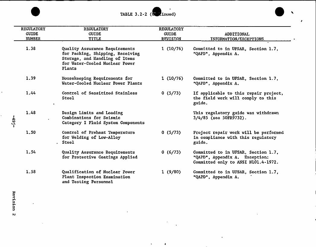
TABLE 3.2-2 ( inued) 0-REGULATORY
GUIDENUMBER
REGULATORYGUIDETITLE
REGULATORYGUIDE
REVISIONADDITIONAL
INFORMATION EXCEPTIONS
1.38 Quality Assurance Requirementsfor Packing, Shipping, ReceivingStorage, and Handling of Itemsfor Water-Cooled Nuclear PowerPlants
1 (10/76) Committed to in UFSAR, Section 1.7,"QAPD", Appendix A.
1.39
1.44
Housekeeping Requirements forWater-Cooled Nuclear Power Plants
Control of Sensitized StainlessSteel
1 (10/76)
0 (5/73)
Committed to in UFSAR, Section 1.7,"QAPD", Appendix A.
If applicable to this repair project,the field work will comply to thisguide.
1.48
1.50
1.54
Design Limits and LoadingCombinations for SeismicCategory I Fluid System Components
Control of Preheat Temperaturefor Welding of Low-AlloySteel
Quality Assurance Requirementsfor Protective Coatings Applied
0 (5/73)
0 (6/73)
This regulatory guide was withdrawn3/4/85 (see 50FR9732).
Project repair work will be performedin compliance with this regulatoryguide.
Committed to in UFSAR, Section 1.7,"QAPD", Appendix A. Exception:Committed only to ANSI N101.4-1972.
1.58 Qualification of Nuclear PowerPlant Inspection Examinationand Testing Personnel
1 (9/80) Committed to in UFSAR, Section 1.7,"QAPD", Appendix A.

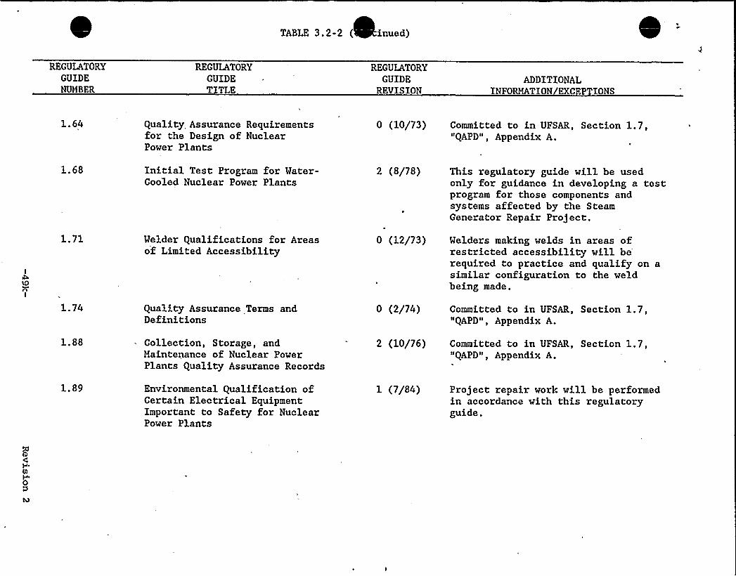
TABLE 3.2-2 ( inued) -REGULATORY
GUIDENUMBER
REGULATORYGUIDETITLE
REGULATORYGUIDE
REVISIONADDITIONAL
INFORMATION EXCEPTIONS
1. 64 Quality Assurance Requirementsfor the Design of NuclearPower Plants
0 (10/73) Committed to in UFSAR, Section 1.7,"QAPD", Appendix A.
1.68
1.71
1.74
Initial Test Program for Water-Cooled Nuclear Power Plants
Welder Qualifications for Areasof Limited Accessibility
Quality Assurance Terms andDefinitions
2 (8/78)
I'
(12/73)
0 (2/74)
This regulatory guide will be usedonly for guidance in developing a testprogram for those components andsystems affected by the SteamGenerator Repair Project.
Welders making welds in areas ofrestricted accessibility will berequired to practice and qualify on asimilar configuration to the weldbeing made.
Committed to in UFSAR, Section 1.7,"QAPD", Appendix A.
1.88
1.89
Collection, Storage, andMaintenance of Nuclear PowerPlants Quality Assurance Records
Environmental Qualification ofCertain Electrical EquipmentImportant to Safety for NuclearPower Plants
2 (10/76)
1 (7/84)
Committed to in UFSAR, Section 1.7,"QAPD", Appendix A.
Project repair work will be performedin accordance with this regulatoryguide.
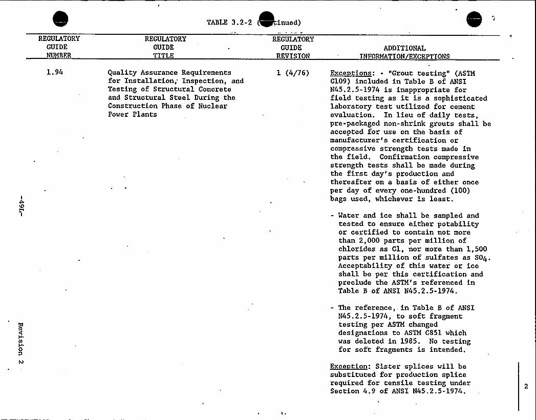
TABLE 3.2-2 inued)
'EGULATORY
GUIDENUMBER
REGULATORYGUIDETITLE
REGULATORYGUIDE
REVISIONADDITIONAL
INFORMATION EXCEPTIONS
1.94 Quality Assurance Requirementsfor Installation; Inspection, andTesting of Structural Concreteand Structural Steel During theConstruction Phase of NuclearPower Plants
1 (4/76) Exce tions: - "Grout testing" (ASTMC109) included in Table B of ANSIN45.2.5-1974 is inappropriate forfield testing as it is a sophisticatedlaboratory test utilized for cementevaluation. In lieu of daily tests,pre-packaged non-shrink grouts shall beaccepted for use on the basis ofmanufacturer's certification orcompressive strength tests made inthe field. Confirmation compressivestrength tests shall be made duringthe first day's production andthereafter on a basis of either onceper day of every one-hundred (100)bags used, whichever is least.
- Water and ice shall be sampled andtested to ensure either potabilityor certified to contain not morethan 2,000 parts per million ofchlorides as Cl, nor more than 1,500parts per million of sulfates as S04.Acceptability of this water or iceshall be per this certification andpreclude the ASTM's referenced inTable B of ANSI N45.2.5-1974.
- The reference,, in Table B of ANSIN45.2.5-1974, to soft fragmenttesting per ASTM changeddesignations to ASTM C851 whichwas deleted in 1985. No testingfor soft fragments is intended.
~Exes tice: Sister splices will besubstituted for production splicerequired for tensile testing underSection 4.9 of ANSI N45.2.5-1974.
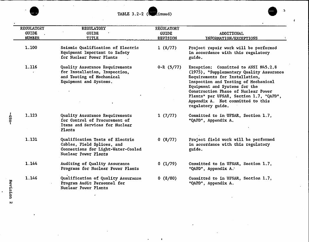
TABLE 3.2-2 ( inued)
REGULATORYGUIDENUMBER
REGULATORYGUIDETITLE
REGULATORYGUIDE
REVISIONADDITIONAL
INFORMATION EXCEPTIONS
1.100 Seismic Qualification of ElectricEquipment Important to Safetyfor Nuclear Power Plants
1 (8/77) Project repair work will be performedin accordance with this regulatoryguide.
1.116 Quality Assurance Requirementsfor Installation, Inspection,and Testing of MechanicalEquipment and Systems.
0-R (5/77) Exception: Committed to ANSI N45.2.8(1975), "Supplementary Quality AssuranceRequirements for Installation,Inspection and Testing of MechanicalEquipment and Systems for theConstruction Phase of Nuclear PowerPlants" per UFSAR, Section 1.7, "QAPD",Appendix A. Not committed to thisregulatory guide.
1.123 Quality Assurance Requirementsfor Control of Procurement ofItems and Services for NuclearPlants
1 (7/77) Committed to in UFSAR, Section 1.7,"QAPD", Appendix A.
1.131 Qualification Tests of ElectricCables, Field Splices, andConnections for Light-Mater-CooledNuclear Power Plants
0 (8/77) Project field work will be performedin accordance with this regulatoryguide.
1.144
1. 146
Auditing of Quality AssurancePrograms for Nuclear Power Plants
Qualification of Quality AssuranceProgram Audit Personnel forNuclear Power Plants
0 (1/79)
0 (8/80)
Committed to in UFSAR, Section 1.7,"QAPD", Appendix A.
Committed to in UFSAR, Section 1.7,"QAPD", Appendix A.
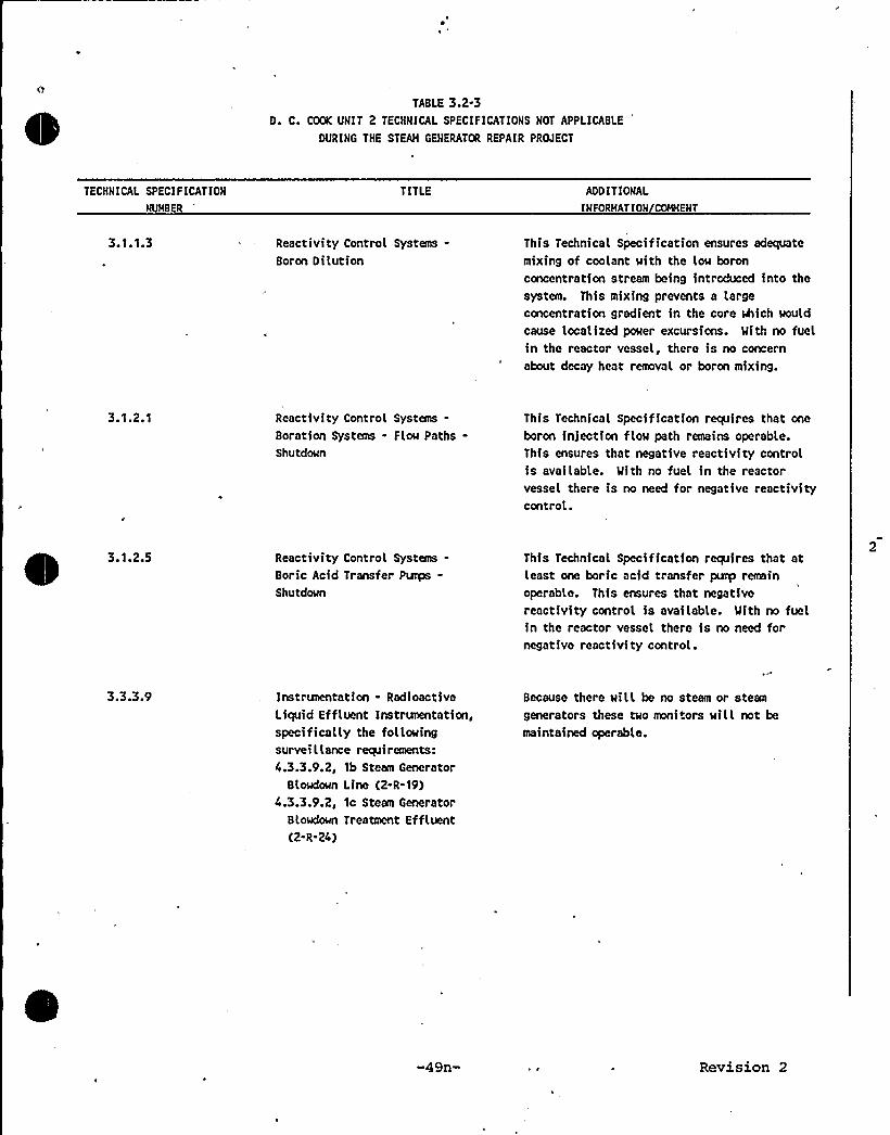
TABLE 3.2-3D. C. COOK UNIT 2 TECHNICAL SPECIFICATIONS NOT APPLICABLE
DURING THE STEAN GENERATOR REPAIR PROJECT
TECHNICAL SPECIFICATION
NUNBER
TITLE ADDITIONAL
INFORHATION COWENT
3.'l.1.3 Reactivity Control Systems-Boron Dilution
This Technical Specification ensures adequate
mixing of coolant with the low boronconcentration stream being introduced into thesystem. This mixing prevents a largeconcentration gradient in the core which would
cause localized power excursions. Mith no fuelin the reactor vessel, there is no concernabout decay heat removal or boron mixing.
3.1.2.1 Reactivity Control Systems-Boration Systems - Flow Paths-Shutdown
This Technical Specification requires that one
boron injection flow path remains operable.This ensures that negative reactivity controlis available. With no fuel in the reactorvessel there is no need for negative reactivitycontrol..
3.1.2.5 Reactivity Control Systems-Boric Acid Transfer Punps-Shutdown
This Technical Specification requires that atleast one boric acid transfer punp remain
operable. This ensures that negativereactivity control is available. With no fuelin the reactor vessel there is no need fornegative reactivity control.
3.3.3.9 Instrunentation - RadioactiveLiquid Effluent Instrunentation,specifically the followingsurvei l lance requirements:4.3.3.9.2, 1b Steam Generator
Slowdown Line (2-R-19)4.3.3.9.2, 1c Steam Generator
Slowdown Treatment Effluent(2-R-24)
Because there will be no steam or steam
generators these two monitors will not be
maintained operable.
-49n- Revision 2
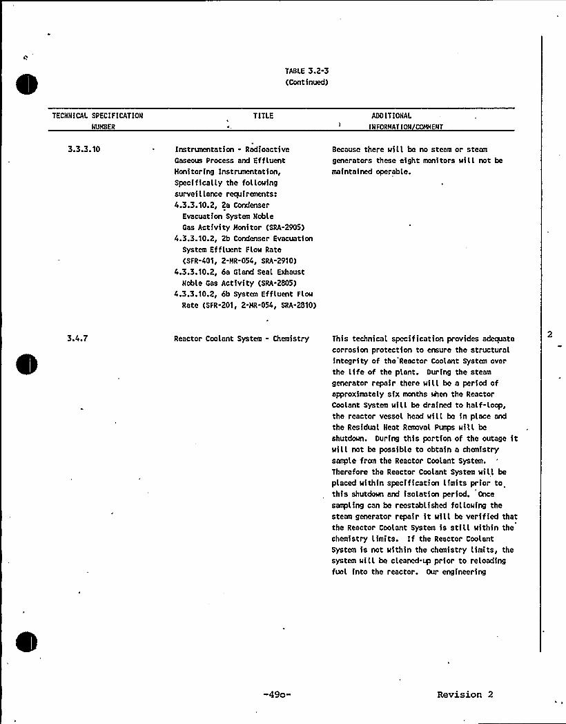
TABLE 3.2-3(Continued)
TECKMICAL SPEC IF ICATIOM
MUHBER
TITLE ADDIT IOMAL
IMFORMATIOM COHMEMT
3.3.3.10 Instrunentaticn - RadioactiveGaseous Process and EffluentHonitoring Instrunentation,Specifically the followingsurveillance requirements:4.3.3.10.2, Za Condenser
Evacuation System Keble
Gas ActivityHonitor (SRA-2905)
4.3.3.10.2, 2b Condenser EvacuationSystem Effluent FLow Rate
(SFR-401, 2-HR-054, SRA-2910)
4.3.3.10.2, 6a Gland SeaL Exhaust
Keble Gas Activity (SRA-2805)
4.3.3.10.2, 6b System Effluent Flow
Rate (SFR.201, 2-HR-054, SRA.2810)
Because there will be no steam or steangenerators these eight monitors wiLL not be
maintained operable.
3.4.7 Reactor Coolant System - Chemistry This technical specif ication provides adequatecorrosion protection to ensure the structuralintegrity of the Reactor Coolant System overthe life of the plant. During the steam
generator repair there will be a period ofaFproximately six months when the ReactorCoolant System wiLL be drained to half-loop,the reactor vessel head wilL be fn place and
the Residual Heat Removal Punps will be
shutdown. During this portion of the outage itwill not be possible to obtain a chemistrysac@le from the Reactor Coolant System.
Therefore the Reactor Coolant System wilL be
placed within speciffcaticn limits prior tothis shutdown and isolation period. Once
san@ling can be reestablished following thestean generator repair it will be verified thatthe Reactor Coolant System is still within thechemistry limits. If the Reactor CoolantSystem is not within the chemistry limits, thesystem wiLL be cleaned-~ prior to reloadingfuel into the reactor. Our engineering
-49o- Revision 2
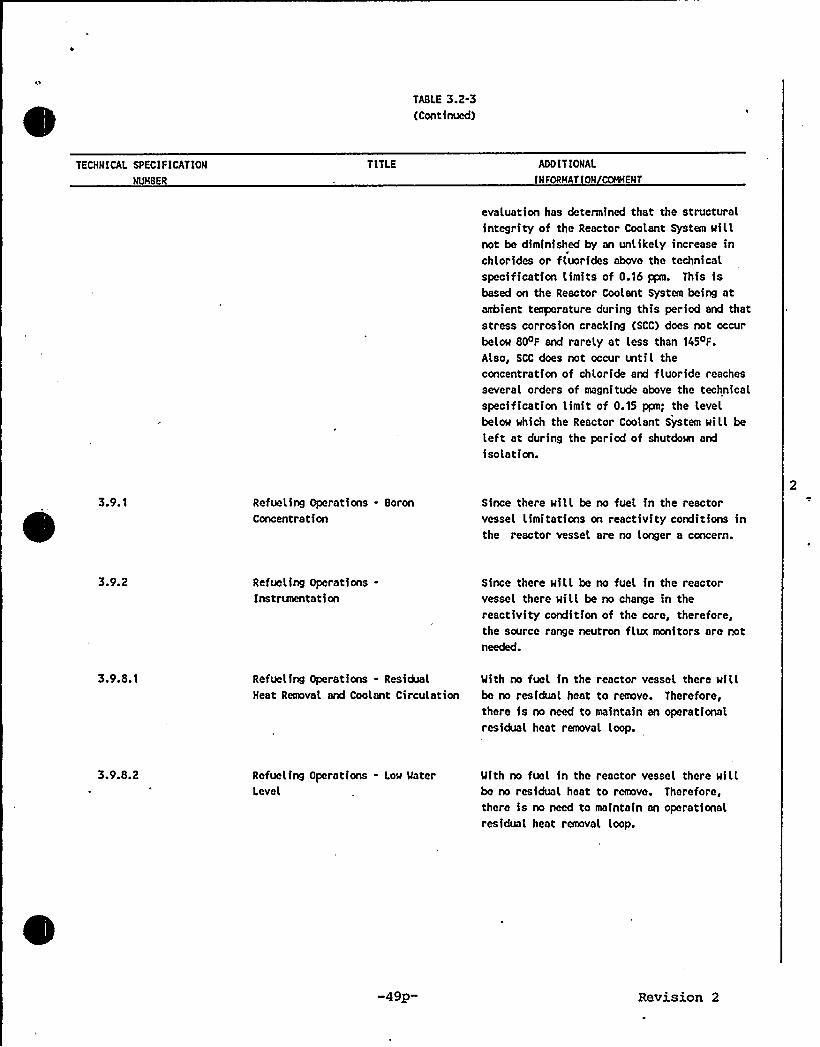
TABLE 3.2-3(Continued)
TECHNICAL SPECIF ICATION
NL%BER
TITLE ADDITIOHAL
INFORHATION COHHENT
evaluation has determined that the structuralintegrity of the Reactor Coolant System willnot be diminished by an unlikely increase inchlorides or fluorides above the technicaLspecification limits of 0.16 ppm. This isbased on the Reactor Coolant System being atanhient temperature during this period and thatstress corrosion cracking (SCC) does not occurbelow 80 F and rarely at Less than 145 F.
Also, SCC does not occur mtiL theconcentration of chloride and fluoride reaches
several orders of magnitude above the technicalspecification limit of 0.15 ppm; the levelbelow which the Reactor Coolant System will be
Left at during the period of shutdown and
isolation.
3.9.1 Refueling Operations - Boron
ConcentrationSince there will be no fuel in the reactorvessel limitations cn reactivity conditions inthe reactor vessel are no Longer a concern.
3.9.2 Refueling Operations-Instrunentati on
Since there will be no fuel in the reactorvessel there will be no change in thereactivity condition of the core, therefore,the source range neutron flux monitors are notneeded.
3.9.8.1 Refueling Operations - ResidualHeat RemovaL and Coolant Circulation
Mith no fuel in the reactor vessel there willbe no residual heat to remove. Therefore,there is no need to maintain an operationalresidual heat removaL loop.
3.9.8.2 Refueling Operations - Low MaterLevel
Mith no fuel in the reactor vessel there willbe no residual heat to remove. Therefore,there is no need to maintain an operationaLresidual heat removal loop.
-49p- Revision 2
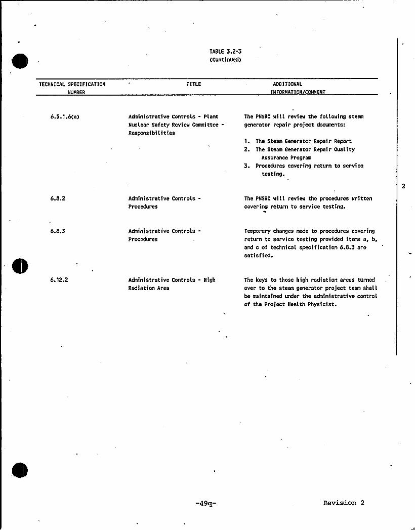
TABLE 3.2-3(Continued)
TECHNICAL SPECI F ICAT ION
NUNBER
TITLE ADO IT IONAL
INFORNATION COGENT
6.5.1.6(a) Adninistrative Controls - PlantNuclear Safety Review Comnittee-Responsibilities
The PNSRC will review the following steam
generator repair project docLments:
1. The Steam Generator Repair Report2. The Steam Generator Repair Ouality
Assurance Program
3. Procedures covering return to servicetesting.
6.8.2 Adninistrative Controls-Procedures
The PNSRC will review the procedures writtencovering return to service testing.
6.8.3 Adninistrative Controls-Procedures
Temporary changes made to procedures coveringreturn to service testing provided items a, b,and c of technical specification 6.8.3 aresatisfied.
6.12.2 Administrative Controls - High
Radiation AreaThe keys to those high radiation areas turnedover to the steam generator project team shallbe maintained under the adainistrative controlof the Project Health Physicist.
-49q- Revision 2
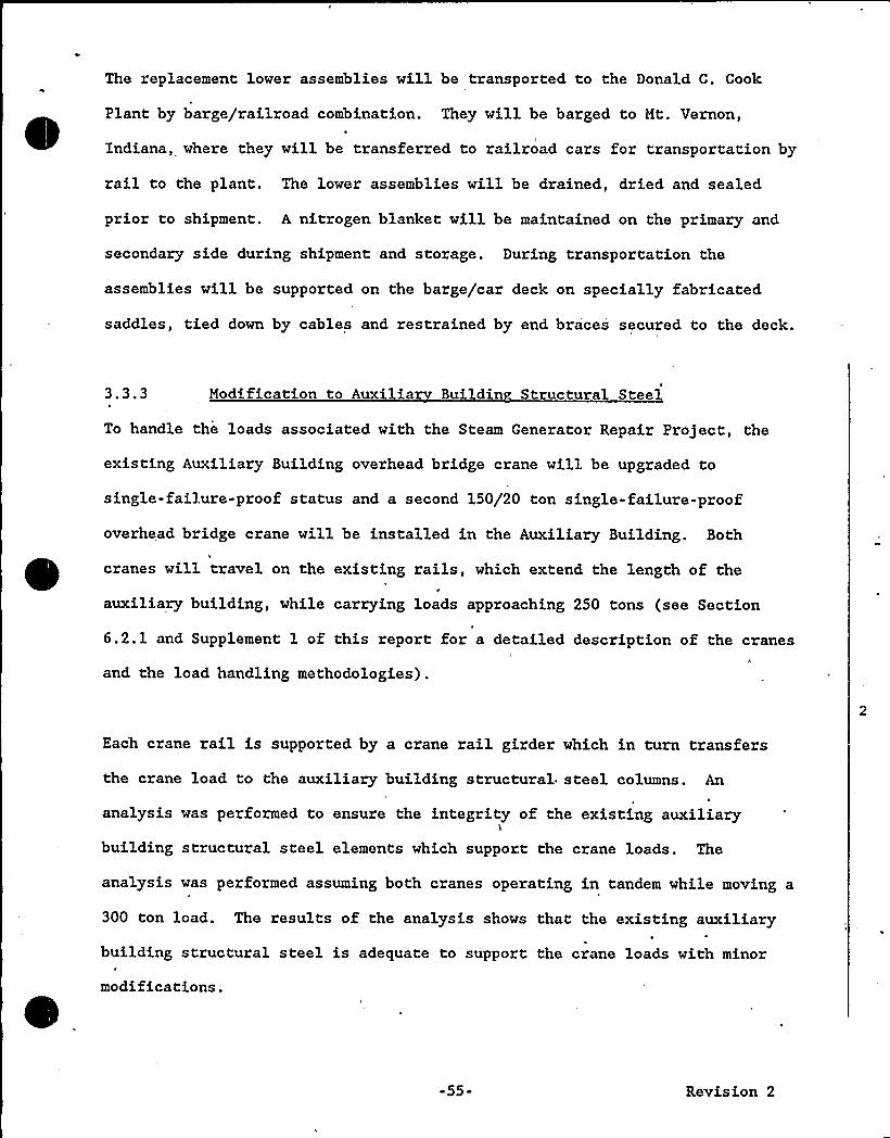
The replacement lower assemblies will be transported to the Donald C. Cook
Plant by barge/railroad combination. They will be barged to Mt. Vernon,
Indiana, where they will be transferred to railroad cars for transportation by
rail to the plant. The lower assemblies will be drained, dried and sealed
prior to shipment. A nitrogen blanket will be maintained on the primary and
secondary side during shipment and storage. During transportation the
assemblies will be supported on the barge/car deck on specially fabricated
saddles, tied down by cables and restrained by end braces secured to the deck.
3.3.3 Modification to Auxilia Buildin Structural Steel
To handle the loads associated with the Steam Generator Repair Project, the
existing Auxiliary Building overhead bridge crane will be upgraded to
single-failure-proof status and a second 150/20 ton single-failure-proof
overhead bridge crane will be installed in the Auxiliary Building. Both
cranes will travel on the existing rails, which extend the length of the
auxiliary building, while carrying loads approaching 250 tons (see Section
6.2.1 and Supplement 1 of this report for a detailed description of the cranes
and the load handling methodologies).
Each crane rail is supported by a crane rail girder which in turn transfers
the crane load to the auxiliary building structural steel columns. An
analysis was performed to ensure the integrity of the existing auxiliary
building structural steel elements which support the crane loads. The
analysis was performed assuming both cranes operating in tandem while moving a
300 ton load. The results of the analysis shows that the existing auxiliary
building structural steel is adequate to support the crane loads with minor
modifications.
-55- Revision 2
This Space Left Intentionall'y Blank
3.3.4 Polar Crane Powe Circuit Re ocation
Approximately 200 feet of the polar crane power supply cable is located in the
cut area of a Unit 2 steam generator doghouse enclosure wall. To eliminate
this cable as a cut interference and at the same time provide maximum
availability of the polar crane, the cable will be permanently rel'ocated priorto the start of the steam generator repair project. The entire cable, from
the containment penetration connection up to the crane, will be replaced to
avoid splicing. The rerouted new cable is of approximately the same length as
the existing cable and therefore will not significantly increase the permanent
combustible fire loading in the containment building. The rerouted cable willbe mounted to the walls per Seismic Class I requirements.
3.4 Post Shutdown Activities
3.4.1 Conta nment Pre a ations
3.4.1.1 Reactor Vessel
Prior to the start of repair project the reactor will be defueled. The upper
internals wi'll be returned to the reactor vessel and the reactor vessel head
reinstalled, The missile shields will be reinstalled and a heavy steel work
—;55a- Revision 2
platform will be assembled over the refueling cavity. Lay-up procedures to
insure reactor vessel cleanliness, prevent foreign objects from entering the
reactor vessel, and minimize corrosion of the reactor coolant system will be
developed.
3.4.1.2 Polar Crane
The polar crane is equipped with a 250-ton capacity main hoist and 35-ton
auxiliary hoist mounted on a single trolley. The polar crane possesses
sufficient capacity to handle all major lifting requirements for the steam
generator project inside containment and can be rerated to a higher capacity
as required; however, rerating of the hoists is not anticipated'.
-55b- Revision 2
Some circuits of the following systems will be temporarily disconnected and/or
removed:
o Fire Detection
Communication
Steam Generator Process Instrumentation
Containment Ventilation
Fuel Handling
Hydrogen Recombiner
600 V Non-Ess Dist. & 120/208 V Lighting
o Seismic Instrumentation
Equipment determined to be essential during the Steam Generator Repair Project
will be relocated, and/or its cable, conduit, and cable trays will be
re-routed as required to maintain the equipment in proper operating condition.
3.4.2.7 Heating, Ventilation and Air Conditioning Ductwork
Ductwork in the removal pathway will be removed or temporary relocated. DuctI
pieces removed will be cleaned, marked snd placed in temporary storage outside
containment until needed for reinstallation.
3.4.2.8 .Steam Generator Insulation
The existing steam generator metallic insulation will be reused. The outer
dimensions of the replacement steam generators duplicates the original steam
generators, although some insulation sections will require modifications to
accommodate the additional hand holes and inspection ports. Sections of
insulation shall be removed, cleaned, wrapped in plastic bags and stored in
strong tight containers. These containers will be stored outside containment
off the ground and protected from the weather. Sequence of removal and
storage location will be documented to facilitate installation. Those
-61- Revision 2
sections requiring modifications will be stored separately to allow rework
prior to installation. The original equipment supplier, Diamond Power
Speciality Corp., will provide procedures and technical supervision for
insulation removal, storage, modifications and installation.
3.4.2.9 Seismic Restraints Removal
The steam generator snubbers will be removed to provide access for handling1
and movement of the steam generators. In addition, the pipe whip restraint at
the main steam pipe will also be removed.
Removal and storage of the snubbers and restraints will be in accordance with
approved procedures and/or specifications. Snubbers are periodically removed
for, ISI testing and off-site disassembly and inspection by an independent
laboratory. Removal and reinstallation procedures will be similar to those
3.4.2.10 Fire Sensors
Thermistor cable tray fire sensors will be pulled back where they extend
beyond removed cable tray sections. These sensor circuits will remain in
service during the steam generator project and will be reinstalled in
accordance with approved procedures.
3.5 Steam Generator Removal Activities
3.5.1 Steam Generato Cuttin ethods and Locations
3.5.1.1 Feedwater and Main Steam Line Piping Cuts
The feedwater and main steam lines will be mechanically cut in two places.
The location of the cuts, the equipment to be used, and the method of cutting
-62- Revision 2
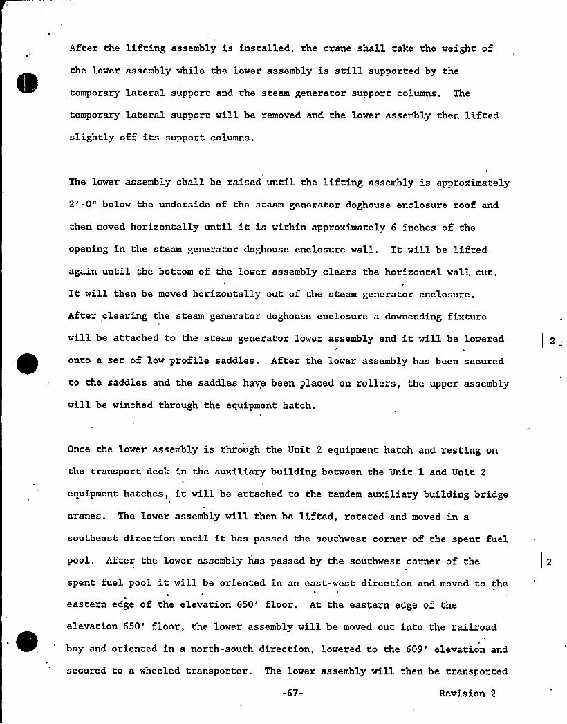
After the lifting assembly is installed, the crane shall take the weight of
the lower assembly while the lower assembly is still supported by the
temporary lateral support and the steam generator support columns. The
temporary lateral support will be removed and the lower assembly then liftedslightly off its support columns.
The lower assembly shall be raised until the lifting assembly is approximately
2'-0" below the underside of the steam generator doghouse enclosure roof and
then moved horizontally until it is within approximately 6 inches of the
opening in the steam generator doghouse enclosure wall. It will be liftedagain until the bottom of the lower assembly clears the horizontal wall cut.
VIt will then be moved horizontally out of the steam generator enclosure.
After clearing the steam generator doghouse enclosure a downending fixture
will be attached to the steam generator lower assembly and it will be lowered
onto a set of low profile saddles. After the lower assembly has been secured
to the saddles and the saddles have been placed on rollers, the upper assembly
will be winched through „the equipment hatch.
Once the lower assembly is through the Unit 2 equipment hatch and. resting on
the transport deck in the auxiliary building between the Unit 1 and Unit 2
equipment hatches, it will be attached to the tandem auxiliary building bridge
cranes. The lower assembly will then be lifted, rotated and moved. in a
southeast direction until it has passed the southwest corner of the spent fuel
pool. After the lower assembly has passed by the southwest corner of the
spent fuel pool it will be oriented in an east-west direction and moved to the
eastern edge of the elevation 650'loor. At the eastern edge of the
elevation 650'loor, the lower assembly will be moved out into the railroad
bay and oriented in a north-south direction, lowered to the 609'levation and
secured to a wheeled transporter. The lower assembly will then be transported
-67- Revision 2
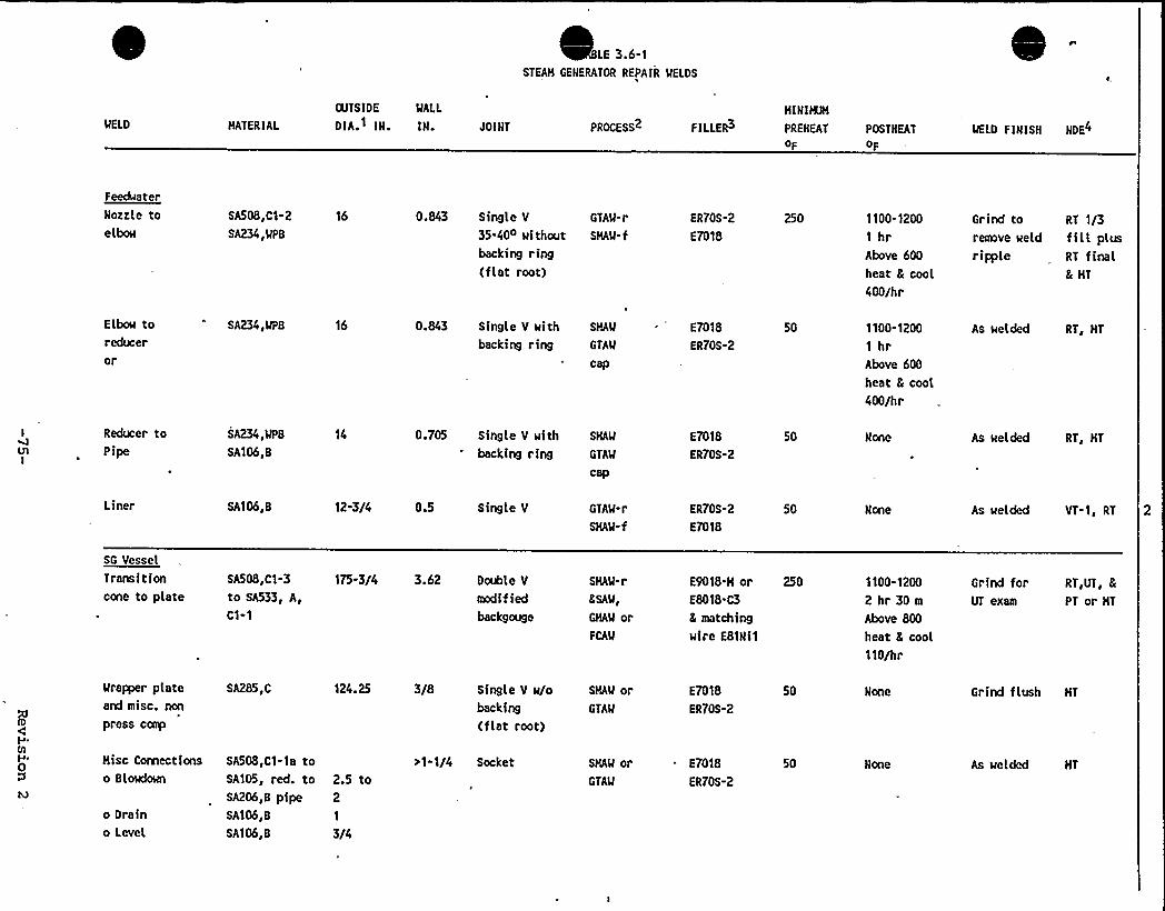
LE 3.6-1STEAH GENERATOR REPAIR MELDS
MELO HATER IAL
OUTSIDE MALL
DIA.1 IN. IN. JOINT PROCESS2 F ILLER3
HINIICH
PREHEAT POSTNEAT
oF oFMELD F INISN NDE4
Feedwater
Nozzle toelbow
SASOS,C1-2 16
SA234,MPB
0.843 Single V
35-40O wi thoutbacking ring(fIat root)
GTAM-r
SHAM-f
ER70S-2
E7018
250 1100-1200
1 hrAbove 600
heat & cool400/hr
Grind toremove weld
ripple
RT 1/3fillplusRT final& HT
Elbow toreduceror
SA234,MPB 16 0.843 Single V with SHAM
backing ring GTAM
cap
E7018
ER70S-2
50 1100-1200
1 hrAbove 600
heat & coot
400/hr
As welded RT, HT
Reducer toPipe
SA234,MPB
SA106,8
14 0.705 Single V with SHAM
backing ring GTA'M
cap
E7018
ER70S-2
50 None As welded RT, HT
Liner SA106,8 12-3/4 0.5 Single V GTAM-r
SHAM-f
ER70S-2
E7018
50 None As welded VT-1, RT 2
SG Vessel
Transitioncone to plate
SA50S,C1-3 175-3/4 3.62 Double V
to SA533, A, modif iedC1-1 backgouge
SHAW-r
&SAW,
GHAM orFCAM
E9018-H or 250
ESOIS-C3
& matchingwire E81Ni1
1100-1200
2 hr 30 m
Above 800
heat & cool110/hr
Grind forUT exam
RT,UT, &
PT or HT
Mra~r plateand misc. non
press comp
SA285,C 124.25 3/8 Single V w/o SHAM orbacking GTAM
(flat root)
E7018
ER70S-2
50 None Grind flush HT
Hisc Coraectionso Slowdown
o Draino Level
SA508,C1-1a toSA105, red. to 2.5 toSA206,B pipe 2
SA106,B 1
SA106,8 3/4
>1-1/4 Socket SHAM orGTAM
E7018
ER70S-2
50 As welded HT
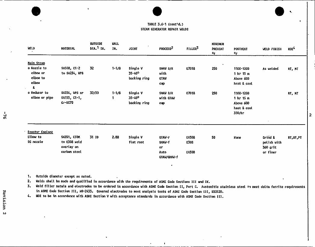
'ABLE
3.6-1 (cont'd.)STEAH GENERATOR REPAIR MELDS
MELD HATERIAI.
CUTS IDE MALL
DIA.1 IN. IN. ~OINT PROCESS2 FILLER3
HINIISH
PREHEAT POSTKEAT
OF OF
MELD FINISH NDE4
Hain Steam
o Nozzle toelbow orelbow toelbow
&
o Reducer toelbow or pipe
SA508, C1-2 32
to SA234, MPB
SA234, MPB or 32/30SA155, C1-1,
Gr-KC70
1-1/8 Single V
35 40o
backing ring
SHAM B/R
withGTAM
cap
1-1/8 Single V SHAM B/R
35.40o with GTAM
backing ring cap
E7018
E7018
250
250
1100.1200
1 hr 15 m
Above 600
heat 8 cool
1100.1200
1hr15mAbove 600
heat S cool350/hr
As welded RT, HT
RT, HT
Reactor Coolant
Elbow toSG nozzle
SA351, CFBH
to E308 weld
overlay on
carbon steel
31 ID 2.88 Single V
flat rootGTAM-r
SHAM-f
orAutoGTAM/GHA'M-f
ER308
E308
ER308
50 None Grind 8
polish with360 gritor finer
RT,UT,PT
1. Outside diameter except as noted.2. Melds shall be made and qualified in accordance with the requirements of ASHE Code Sections III and IX.3. Meld filler metals and electrodes to be ordered in accordance with ASHE Code Section II, part C. Austenitic stainless steel to meet delta ferrite requirements
in ASHE Code Section Ill, NB-2433. Covered electrodes to meet analysis tests of ASHE Code Section III, NB2420.
4. NDE to be in accordance with ASHE Section V with acceptance standards in accordance with ASHE Code Section III.
In addition, a Plant/Project interface document shall be implemented to define
areas of responsibility, communications, control, and interface between the
Project Radiation Protection/ALARA Group and the Plant Radiation Protection
Section. Regular'eetings between members of these two groups will be held to
insure adequate communications and dissemination of information.
-82a- Revision 2

o No changes are expected due to differences in initial conditions (zero
load steam temperature and pressure are identical for the unit with
repaired steam generators). The no load steam generator mass decreases
insignificantly (-2.0 percent).
Therefore the conclusions of the existing steam line break analyses remain
valid for the repaired steam generators.
6.1.2.5 Steam System Piping Failures
Refer to Section 6.1.2.4 for discussion that applies to this accident as well.
6.1.2.6 Loss of External Load ,
Donald C. Cook Unit 2 is designed to have full load rejection capability, and
a reactor trip may not occur following a loss of external load. It is
expected that steam dump valves would open in such a load rejection, dumping
steam directly to the condenser. Reactor coolant temperature and pressure do
not significantly increase if the turbine bypass system and pressurizer
pressure control system are functioning properly. If the steam dump valves do,
not operate, the reactor will trip due to high pressurizer pressure signal,
high pressurizer level signal, or overtemperature T signal. Primarily to
show the adequacy of the pressure-relieving devices and to demonstrate core
protection margins, the Donald C. Cook FSAR and analysis of record analyze
cases where the steam dump valves do not operate, and there is no direct
reactor trip due to a turbine trip. It is shown in the FSAR and the analysis
of record that the accident criteria on system pressure and DNB are not
violated in any of the loss-of-load cases.
-144- Revision 2
An accident involving the dropping or tipping of the steam generators during
the removal process is considered highly unlikely because of the strictcontrols which will be placed on the movement process. In the unlikely event
that an accident involving the steam generators does occur, our reviews have
determined that the only potential interactions with shared systems of
significant concern involve the spent fuel pool cooling equipment located in
the vicinity of the load path. However, the slight potential for damaging
spent fuel pool cooling equipment is not considered to represent an unreviewed
safety question as defined in 10 CFR 50.59. This conclusion is based on the
various malfunction analyses presented in Chapter 9.4 of the FSAR. These
analyses conclude that it is not possible for a piping failure to causeI
drainage of the pool below the top of the stored fuel elements. In the event
all. cooling for the pool is lost, it would take a minimum of 8 hours for the
temperature in the pool to reach 180oF (which still allows 32oF margin to
boiling). Thus, sufficient time exists to either restore cooling capability
or replace water which could be lost through boiloff to prevent damage to the
stored fuel elements.
6.3 Fire Protection Evaluation\
The effect of a Unit 2 construction fire was evaluated by assuming that the
equipment in the Unit 2 containment and Auxiliary Building fire areas directlyaffected by construction activities would be damaged. Loss of all equipment
in the combined fire areas would not cause loss of Unit 1 safe shutdown
capability.
The fixed combustible loading of these fire areas will not be significantly
affected by construction activities. Transient combustible loading in the
construction areas will increase beyond the levels assessed in the Fire
Hazards Analysis for normal conditions.-163-'evision 2
The Safe Shutdown Capability Assessment exemption requests and fire barrier
evaluations for the affected fire areas were reviewed to assess the impact of
increased fire loadings and fire hazards due to construction activities.
Construction activities were determined not to impact the validity of these
evaluations with respect to Unit 1 shutdown capability provided there is no
continuity of combustibles, such as wooden temporary stairs and trash chutes,
between the Crane Bay and the 650'levation of the Auxiliary Building which
could promote rapid fire spread. Temporary stairs and other structures
connecting these elevations will be made primarily of non-combustible
materials or compensatory measures will be provided.
The repair contractor will operate under existing plant procedures and
administrative controls with the exception of areas turned over to his direct
control for construction, access, and laydown. The repair contractor willprepare a fire protection program to govern work activities in the areas under
his control which will be designed to minimize construction fire hazards.
6.4 Analysis of Significant. Hazards Consideration
This section presents, pursuant to 10 CFR 50.91, the analysis which sets forth
the determination that the Steam Generator Repair Project does not involve any
Significant Hazard Consideration as defined by 10 CFR 50.92.
In addition to the appraisal on the significant hazards issue using th'
standards in 10 CFR 50.92, which are presented below, it is important to note
that the Steam Generator Repair Project proposed by I&NECo involves practices
that have been successfully implemented at two other commercial nuclear power
plants, namely, the steam generator repairs completed by the Virginia Electric
-163a- Revision 2
and Power Company for the Surry Power Station and by the Visconsin Electric
Power Company for the Point Beach Nuclear Plant, Unit 1. The repair project
is also similar to the repair projects conducted by the Carolina Power and
Light Company for the H. B. Robinson Steam Electric Plant, Unit No. 2 and by
the Florida Power and Light Company for the Turkey Point Plant Units 3 and 4.
6.4.1 Criterion 1
Involve a significant increase in the probability or consequences of an
accident.
The Steam Generator Repair Project does not affect the probability or
consequence of an accident. The probability or consequence of an accident is
determined by the design and operation of plant systems. The repair project
involves the replacement of the Donald C. Cook Unit 2 Steam Generator Lower
Assemblies. Due to the almost identical design of. the replacement lower
assemblies the repair of the Donald C. Cook Unit 2 steam generators is a
replacement in kind and will not change the design or operation of plant
systems. Thus, this repair does not involve a significant increase in the
probability or consequences of an accident previously evaluated.
6.4.2 Cr terion 2
Create the possibility of a new or different kind of accident from any
accident previously evaluated.
The possibility of a new or different kind of accident is not created by the
repair to the Donald C. Cook Unit 2 steam generators. All components and
piping will be reinstalled to meet the original design and configurations and
installation requirements. Therefore, because there will be no changes to the
plant and plant systems design no new or different accidents are created.
Revision 2
6.4.3 Criterion 3
Involve a significant reduction in a margin of safety.
Section 2.2 of this report illustrates that, although certain design
enhancements have been made, the steam generator repair will result in very
little change to the original operating parameters. Therefore, the impact on
the accident analysis, as shown in Section 6.1 will be insignificant and there
will be no significant resolution in the margin of safety.
-165- Revision 2
7.3.2 Re ional Historic Archeolo cal A hitectural Scenic
Cultural and Natural Features
No known historic, archeological, architectural or natural resources
exist on the portion of the plant site affected by the Steam Generator
Repair Project.
The access road used during plant construction parallels the beach and
will be used for light construction traffic during the repair project.
This traffic may pose an aesthetic impact to individuals using the beach
for recreation, however, this is a temporary impact that will end with
the completion of the repair project.
7.3.3 ~Hdrolo
7.3.3.1 Ground Water
No impact to the site ground water is expected to occur as a result of
the Steam Generator Repair Project.
7.=3.3.2 Surface Water
No impact to the surface water associated with the plant site is
expected to occur as a result of the construction phase of the Steam
Generator Repair Project. In addition, the repaired steam generators
will have essentially the same amount of blowdown discharged during
operation as do the original steam generators and it is anticipated that
there will be no changes to the plant NPDES permit.
Revision 2
7.3.4 ~Geolo
There will be no geological impacts as the result of the Steam Generator
Repair Project. Excavation, grading, and compaction will occur in
limited amounts and these actions will occur in areas previously
disturbed (i.e. parking lots, roadways, and laydown areas).
7.3.5 ~Ecolo
7.3.5.1 Terrestrial Ecology
There will be 'no impacts to the terrestrial ecology surrounding the
- plant site for the following reasons:
o No habitat will be removed as a result of the Steam Generator
Repair Project since all activities related to the repair project
will occur on previously disturbed area (i.e. existing access
roads, parking lots, laydown area.
o Since the area affected is already subjected to the intrusion of
man and machinery (i.e. security patrols, existing security lights,
and normal plant operations), animals residing in the areas
adjacent to the construction related activities should not be
disturbed by the increased activity.
7.3.5.2 Aquatic Ecology
As discussed in Section 7.3.3.2 neither the construction phase of the
Steam Generator Repair Program or the operation of the repaired steam
generators will impact the .aquatic ecology associated with the plant
site.
-171- Revision 2
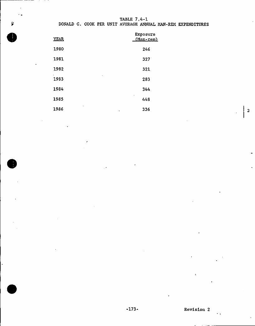
TABLE 7.4-1DONALD C. COOK PER UNIT AVERAGE ANNUAL MAN-REM EXPENDITURES
YEARExposure
Man-rem
1980 246
1981 327
1982 321
1983 283
1984
1985 448
1986 336
-173- Revision 2
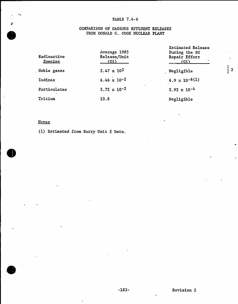
TABLE 7.4-6
COMPARISON OF GASEOUS EFFLUENT RELEASESFROM DONALD C. COOK NUCLEAR PLANT
Radioactive~seciee
Noble gases
Iodines
Particulates
Tritium
Average 1985Release/Unit
C
2.47 x 10³
6.46 x 10 2
3.72 x 10 2
10.8
Estimated ReleaseDuring the SG
Repair EffortC
Negligible
6.9 x 10⁻⁶(1)
2.92 x 10 4
Negligible
otes
(1) Estimated from Surry Unit 2 Data.
-183- Revision 2
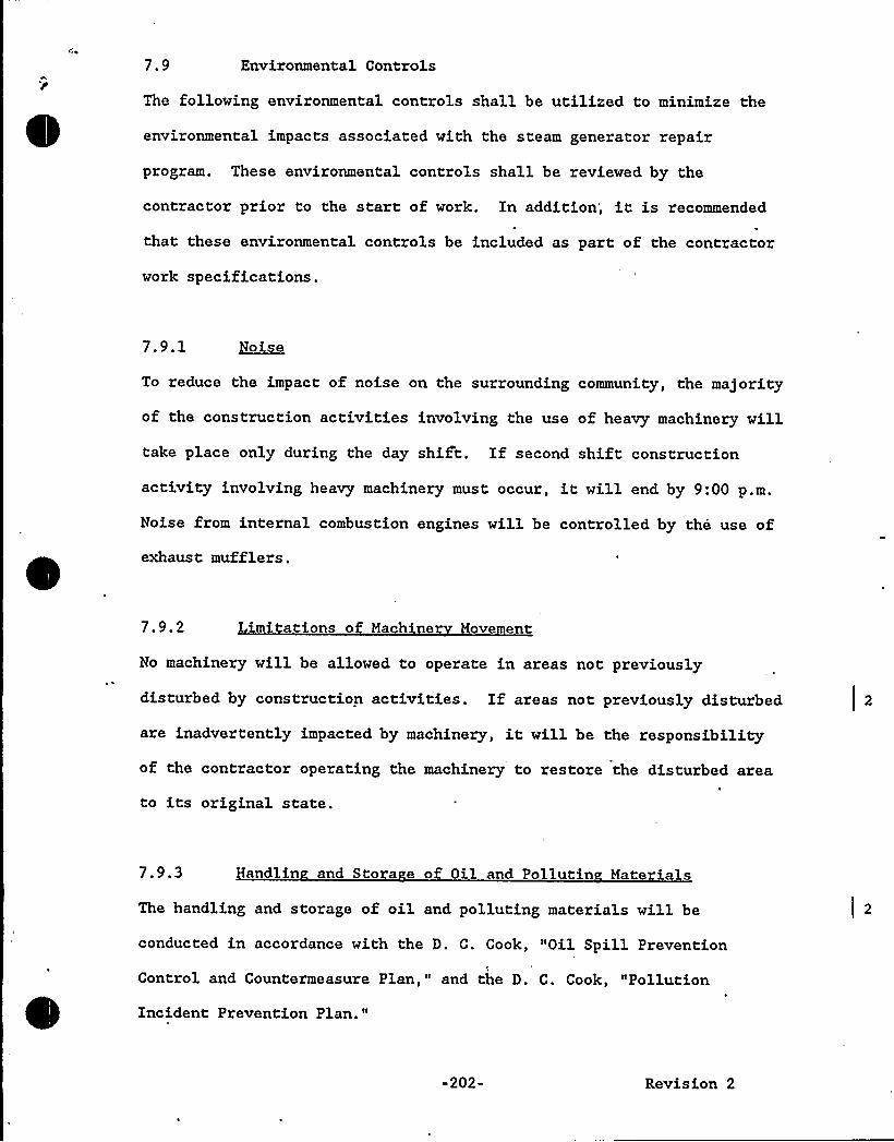
7.9 Environmental Controls
The following environmental controls shall be utilized to minimize the
environmental impacts associated with the steam generator repair
program. These environmental controls shall be reviewed by the
contractor prior to the start of work. In addition; it is recommended
that these environmental controls be included as part of the contractor
work specifications.
7.9.1 Noise
To reduce the impact of noise on the surrounding community, the majority
of the construction activities involving the use of heavy machinery willtake place only during the day shift. If second shift construction
activity involving heavy machinery must occur, it will end by 9:00 p.m.
Noise from internal combustion engines will be controlled by the use of
exhaust mufflers ~
7.9.2 Limitations o a h e Movement
No machinery will be allowed to operate in areas not previously
disturbed by construction activities. If areas not previously disturbed
are inadvertently impacted by machinery, it will be the responsibility
of the contractor operating the machinery to restore the disturbed area
to its original state.
7.9.3 Handlin and Sto a e of Oil and Pollutin Materials
The handling and storage of oil and polluting materials will be
conducted in accordance with the D. C. Cook, "Oil Spill Prevention
Control and Countermeasure Plan," and the D. C. Cook, "Pollution
Incident Prevention Plan."
-202- Revision 2
7.9.4 Environmental Monitorin
Periodic inspections of the construction activities will be conducted.
If any of the construction activities appear to be causing significant
environmental impacts, appropriate actions will be taken.
7.9.5 Permits
A list of State and local permits needed to begin construction
activities at D. C. Cook will be developed by the D. C. Cook
Environmental Section and the AEPSC Radiological Support Section.
The AEPSC Radiological Support Section will be responsible for
obtaining the required permits.
7.10 Conclusion
It is concluded that with the proper mitigation practices as outlined in
the Environmental Controls Section of thi's report, no significant
adverse environmental impact will result from the proposed activity,that there are no preferable alternatives to the proposed action and
that the impacts associated with the repair program are outweighed by
its benefits.
It is further concluded that the site preparation work, as described in
Section 3, does not involve an unreviewed environmental question
pursuant to Part II, Section 3.1 of the Donald C. Cook Plant
Environmental Technical Specifications.
-203- Revision 2
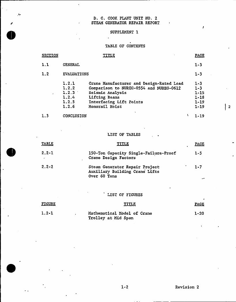
D. C. COOK PLANT UNIT NO. 2STEAM GENERATOR REPAIR REPORT
SUPPLEMENT 1
TABLE OF CONTENTS
SECT ON TITLE PAGE
1.2
GENERAL
EVALUATIONS
1-3
1-3
1.2.11.2.21.2.31.2.41.2.51.2.6
Crane Manufacturer and Design-Rated LoadComparison to NUREG-0554 and NUREG-0612Seismic AnalysisLifting BeamsInterfacing Lift PointsMonorail Hoist
1-31-31-151-181-191-19
1.3 CONCLUSION 1-19
TABLE
2.2-1
2.2-2
LIST OF TABLES
~TI LE
150-Ton Capacity Single-Failure-ProofCrane Design Factors
Steam Generator Repair ProjectAuxiliary Building Crane'iftsOver 60 Tons
PAGE
1-5
1-7
LIST OF FIGURES
FIGURE TITLE PAG
1.2-1 Mathematical Model of CraneTrolley at Mid Span
1-20
1-2 Revision 2
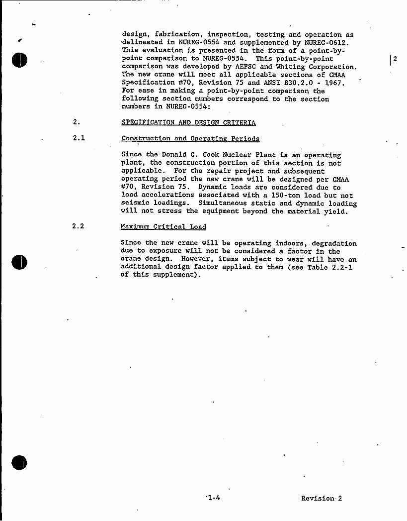
design, fabrication, inspection, testing and operation asdelineated in NUREG-0554 and supplemented by NUREG-0612.This evaluation is presented in the form of a point-by-point comparison to NUREG-0554 'his point-by-pointcomparison was developed by AEPSC and Whiting Corporation.The new crane will meet all applicable sections of CMAASpecification ¹70, Revision 75 and ANSI B30.2.0 - 1967.For ease in making a point-by-point comparison thefollowing section numbers correspond to the sectionnumbers in NUREG-0554:
2. C T
2.1 Construct on and 0 eratin Per ods
Since the Donald C. Cook Nuclear Plant is an operatingplant, the construction portion of this section is notapplicable. For the repair project and subsequentoperating period the new crane will be designed per CMAA¹70, Revision 75. Dynamic loads are considered due toload accelerations associated with a 150-ton load but notseismic loadings. Simultaneous static and dynamic loadingwill not stress the equipment beyond the material yield.
2.2 Maximum Crit cal Load
Since the new crane will be operating indoors, degradationdue to exposure will not be considered a factor in thecrane design. However, items subject to wear will have anadditional design factor applied to them (see Table 2.2-1of this supplement).
'1-4 Revision 2
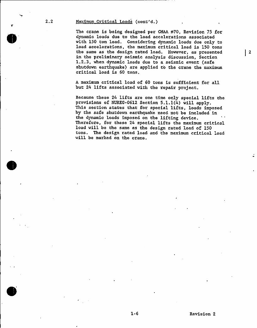
2.2 Maximum Critical Loads (cont'd.)
The crane is being designed per CMAA ¹70, Revision 75 fordynamic loads due to the load accelerations associatedwith 150 ton load. Considering dynamic loads due only toload acceleiations, the maximum critical load is 150 tonsthe same as the design rated load. However, as presentedin the preliminary seismic analysis discussion, Section1.2.3, when dynamic loads due to a seismic event (safeshutdown earthquake) are applied to the crane the maximumcritical load is 60 tons.
A maximum critical load of 60 tons is sufficient for allbut 24 lifts associated with the repair project.
Because these 24 lifts are one time only special lifts theprovisions of NUREG-0612 Section 5.1.1(4) will apply.This section states that for special lifts, loads imposedby the safe shutdown earthquake need not be included inthe dynamic loads imposed on the lifting device.Therefore, for these 24 special lifts the maximum criticalload will be the same as the design rated load of 150tons. The design rated load and the maximum critical loadwill be marked on the crane.
1-6 Revision 2
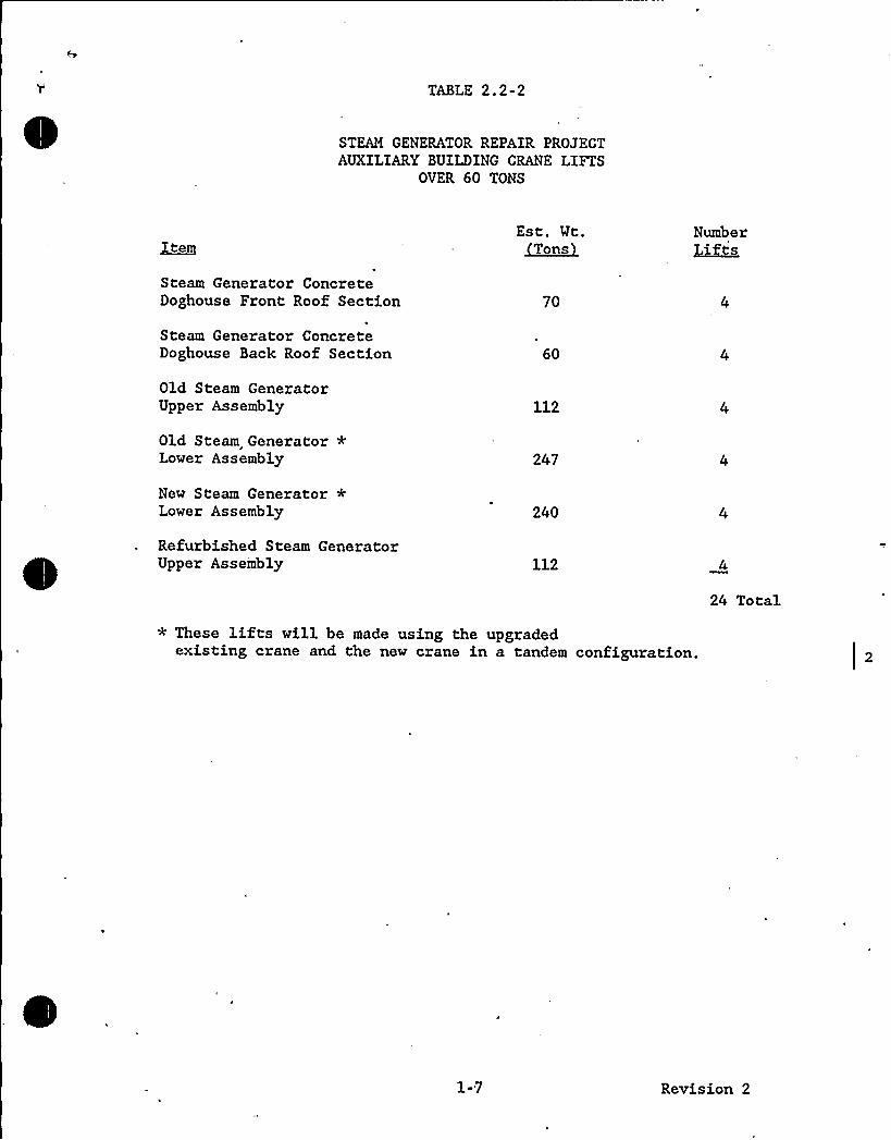
TABLE 2.2-2
STEAM GENERATOR REPAIR PROJECTAUXILIARYBUILDING CRANE LIFTS
OVER 60 TONS
IteryEst. Wt.~owns
Number~Lff s
Steam Generator ConcreteDoghouse Front Roof Section 70
Steam Generator ConcreteDoghouse Back Roof Section 60
Old Steam GeneratorUpper Assembly 112
Old Steam Generator *Lower Assembly 247
New Steam Generator *Lower Assembly 240
Refurbished Steam GeneratorUpper Assembly 112
24 Total
* These lifts will be made using the upgradedexisting crane and the new crane in a tandem configuration.
1-7 Revision 2

TABLE 2.2-2
STEAM GENERATOR REPAIR PROJECTAUXILIARYBUILDING CRANE LIFTS
OVER 60 TONS
ItemEst. Wt.~Tons
NumberLifts
Steam Generator ConcreteDoghouse Front Roof Section 70
Steam Generator ConcreteDoghouse Back Roof Section 60
Old Steam GeneratorUpper Assembly 112
Old Steam Generator *Lower Assembly 240
New Steam Generator *Lower Assembly 247
Refurbished Steam GeneratorUpper Assembly 112
24 Total
* These lifts will be made using the upgradedexisting crane and the new crane in a tandem configuration.
1-7 Revision 2
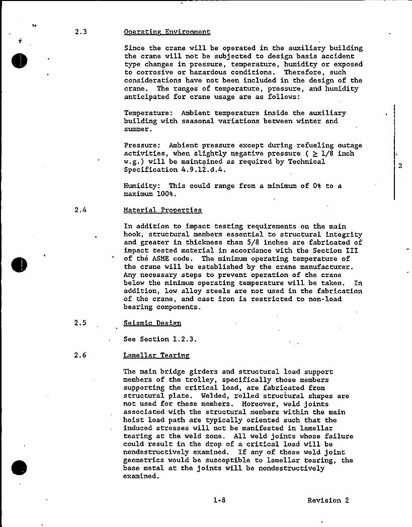
2.3 0 eratin Environment
Since the crane will be operated in the auxiliary buildingthe crane will not be subjected to design basis accidenttype changes in pressure, temperature, humidity or exposedto corrosive or hazardous conditions. Therefore, suchconsiderations have not been included in the design of thecrane. The ranges of temperature, pressure, and humidityanticipated for crane usage are as follows:
Temperature: Ambient temperature inside the auxiliarybuilding with seasonal variations between winter andsummer.
Pressure: Ambient pressure except during refueling outageactivities, when slightly negative pressure ( ) 1/8 inchw.g.) will be maintained as required by TechnicalSpecification 4.9.12.d.4.
Humidity: This could range from a minimum of 0% to amaximum 100%.
Material Pro erties
2.5
In addition to impact testing requirements on the mainhook, structural members essential to structural integrityand greater in thickness than 5/8 inches are fabricated ofimpact tested material in accordance with the Section IIIof the ASME code. The minimum operating temperature ofthe crane will be established by the crane manufacturer.Any necessary steps to prevent operation of the cranebelow the minimum operating temperature will be taken. Inaddition, low alloy steels are not used in the fabricationof the crane, and cast iron is restricted to non-loadbearing components.
Seismic Desi n
2.6
See Section 1.2.3.
Lamellar Tearin
The main bridge girders and structural load supportmembers of the trolley, specifically those memberssupporting the critical load, are fabricated fromstructural plate. Welded, rolled structural shapes arenot used for these members. Moreover, weld jointsassociated with the structural members within the mainhoist load path are typically oriented such that theinduced stresses will not be manifested in lamellartearing at the weld zone. All weld joints whose failurecould result in the drop of a critical load will benondestructively examined, If any of these weld jointgeometries would be susceptible to lamellar tearing, thebase metal at the joints will be nondestructivelyexamined.
1-8 Revision 2
2.7 St uctura ti ue
As stated in Section 2.1, the crane will not be used forplant construction lifts. The allowable stress range forthe fatigue design of this crane is higher than the normaldesign allowables of Crane Manufacturers Association ofAmerica (CMAA) Specification No. 70-1975. As a result, afatigue analysis will not be performed, since it is not agoverning factor in design of the crane.
2.8 Weldin Procedures
Welding, welding procedures (pre heat, post weld heattreatments), and welder qualifications are in accordancewith AWS Dl.l "Structural Welding Code." Further,low-alloy materials will not be used in the main loadsupport structure.
SAFETY FEATURES
3.2 Auxiliar S stems
The auxiliary 20 ton hoist is of single-failure-proofdesign.
Where dual components are not provided within either hoistmechanical load path, redundancy is provided through anincreased design factor on such components as required perNUREG 0612.
3.3 Elect ic Cont ol S stems
Limit controls are incorporated to minimize the likelihoodof inflicting damage to the hoisting drive machinery andstructure that otherwise might occur through inattentiveand/or unskilled operator action. An emergency stopbutton will be added to the radio remote control unit .thatwill interrupt the power supply to the crane and stop allcrane motion.
3.4 Eme enc Re a s
This crane is designed so that, should a malfunction orfailure of controls or components occur, it will be ableto hold the load while repairs and adjustments are made.
HOISTING MAC NERY
4.1 Reevin S stem
— The static-inertia design factor of the wire rope, withall parts in the dual system supporting the DRL is 11 to1. Such conservative design more than surpassesrequirements to sustain the dynamic effects of loadtransfer due to the loss of one of the two independentrope systems with an ample design margin remaining in the
1-9 Revision 2
six parts supporting the load. The maximum load(including static and inertia forces) on each individualwire rope in the dual reeving system with the MCL attachedwill not exceed 10$ of the manufacturer's publishedbreaking strength. Compliance to this recommendationrequires high alloy rope. By definition, reverse bends donot exist in the reeving system of the main hoist.Studies have been conducted to establish the effects ofreverse bend on fatigue life. In consideration for thegeometry of wire rope (helix) construction, unless thedistance between th'e sheaves in the load block and headblock are under one lead of the wire rope, a reverse bendcycle is not incurred. Moreover, the ratio of rope tosheave diameter in the only qualifying area of the hoistmechanism is related to the drum, which is 30 to 1; 125%of minimum requirement per CMAA Spec. ¹70, Rev. 75.
The pitch diameter of running sheaves and drums shall bein accordance with CMAA Spec. ¹70, Rev. 75. All fleetangles within the main hoist reeving are within therecommended 3 1/2 degrees. The crane is equipped with anequalizer beam/fixed sheave arrangement that provides twoseparate and complete reeving systems.
Protection against excessive wire rope wear and fatiguedamage will be ensured through periodic inspection andmaintenance.
4.2 Drum Su ort
The indicated drum support provisions are included in thedesign which, as required, would insure againstdisengagement of the drum from its braking control system.
4.3 Head and Load Blocks
Both reeving systems associated with this crane are-designed with dual reeving. This design will ensure thevertical load balance is maintained.
Each load-attaching point (sister hook and eye bolt) isamply designed to sustain 200% of the 150-ton DRL. Theoverhead crane shall be load tested at 125% of the 150-tonDRL.
Nondestructive examination of the sister hook and eye boltwill be performed. After successful completion of theload test, a complete inspection of the crane, including anondestructive examination of the sister hook and eyebolt, will be performed.
4.4 Hoistin S eed
The main hoist full rated load speed of approximately 4.5FPM is less than the suggested operating speed in the"slow" column of Figure 70-6 of CMAA specification ¹70.
Revision 2
Further, the rope line speed at the drum at approximately27 FPM is considered to be conservative.
Desi n A ainst Two-B ockin
The main hoist is equipped with two independent travellimit control devices in addition to a load sensingsystem, as suggested, to insure against two-blocking.Actuation of hoist travel limit switches or load sensingdevices will deenergize the hoist drive. In addition, themechanical holding brake will have the capability towithstand the maximum torque of the driving motor,
4.6 Liftin Device
The lifting beams and other devices attached to the cranehook block will be designed to have factors of safetybased on guidelines noted in NUREG-0612 and NUREG-0554.Each device will be able to support a load of three timesthe load (static and dynamic) being handled withoutpermanent deformation as recommended in Section 4,6 ofNUREG-0554.
4.7 Wire Ro e Protection
Operation of the hoist is only to be attempted with thetrolley and block aligned over the center of the load fora vertical lift.
4.8 Mach ne Ali nment
The provisions of this paragraph are incorporated in thedesign of the overhead crane.
4.9 Hoist B akin S stem
The provisions of this paragraph are incorporated in thedesign of the overhead crane.
5.
5.1
BRIDGE AND TROLLEY
Brakin Ca ac tThe bridge and trolley drives will each be provided withan appropriately sized electric holding brake which, uponinterruption of power, is applied whether through operatoraction or violation of travel limit provisions on thetrolley and restrict area limit controls for the bridge.Further, these brakes are capable of being operatedmanually.
The AC induction-motors and magnetic controls utilized forthese drives are not prone to an overspeed condition,which is attributed to inherent operating characteristics.Therefore, overspeed limit controls for the bridge and
1-11 Revision 2
trolley motion equipped with this type of drive wouldrepresent a needless feature. Moreover, the motorcontrols are provided with adequate overload protection.
The mechanical drive components are designed to sustainmaximum peak loadings capable of being transmitted byeither the motor or brake under all attitudes of normalcrane operation.
All other recommendations of this section are compatiblewith the design of the crane.
5.2 Safet Sto s
As stated in Section 5.1, an overspeed conditionconsidering the type of drive used for the bridge andtrolley is not a concern with this equipment.Appropriately designed and sized bumpers and stops areprovided in accordance with CMAA Spec. @70 Rev. 75 and areadequate to absorb the energy of the trolley and bridge inthe event of limit switch malfunction.
6. R V AN CO TROLS
6.1 Driver Selection
The main hoist motor was selected on the basis of hoistingthe design-rated load (150 tons) at the design hoistingspeed. Further, all proper and due consideration wasgiven to the design of related- mechanical and structuralcomponents to adequately resist peak torques transmittedby this motor within normal design limits.
Hoist overspeed and overload sensing-limit controlprovisions have been incorporated to guard against, suchoccurrences. Additionally, the hoist holding brakes arecapable of controlling the design rated load within the 3inches .(8 cm) specified stopping distance. In addition,emergency power disconnect switches will be located atoperating floor level to interrupt power to- the craneindependent of the crane controls. Since the MCL is lessthan the DRL, administrative controls will be establishedto reset the overloading sensing device.
6.2 Drive Control S stems
The design considerations discussed in this section havebeen addressed and incorporated as appropriate except forthe restriction of simultaneous operation of motions. Thecrane is not used to handle spent fuel assemblies.
6.3 Malfunction Protectio
Features to sense, respond to, and secure the load in theevent of hoist overspeed, overcurrent, overload, over
Revision 2
travel, and loss of one rope of the dual reeving systemhave been incorporated.
6.4 Slow S eed D ives
Features recommended in this paragraph will beincorporated as part of the motion control circuitry.
6.5 Safet Devices
Each hoist is equipped with two independent hoistovertravel limit controls.
6.6 Control Stations
Since this crane is not equipped with a cab, the completeoperating control system and emergency controls for thecrane will be located on a radio remote control unit. Inaddition, as stated earlier emergency power disconnectswitches will be located at operating floor level tointerrupt power to the crane independent of the radioremote control unit.
Since the design rated load is greater than the maximumcritical load, administrative controls will be establishedto ensure that the resetting of the overload sensingdevice is properly conducted.
7. NSTAL TION INSTRUCTIONS
7.1 Genera
Complete operation, maintenance, installation and testinginstructions will be provided for the overhead crane bythe crane manufacturer.
7.2 Const uction and 0 eratin Per ods
As discussed in Section 2.1 this crane will not be usedfor plant construction. The crane will be designed forClass A-1 service as defined in CMAA Specification ¹70,Revision 75. The allowable design stress limits will notbe exceeded during the repair project.
During and after installation of the crane, the properassembly 'of electrical and structural components should beverified.
8.- TES ING A D REVENTIV IN N CE
8.1 General
A complete check will be made of all the crane'smechanical and electrical systems to verify the properinstallation and to prepare the crane for testing.
1-13 Re~ision 2
Proof-testing of a subcomponent is an independentverification of the subcomponent's ability to perform.The main hook block and eye bolt of the hook blockassembly will be tested at 200% of the design-rated load(DRL). Before and after this test, the hook and eye boltwill be subject to nondestructive examinations. The wirerope supplier will test a section of wire rope bysubjecting it to an overload condition until breakingoccurs. No other components of the crane shall beproof-tested. Upon successful completion of the aboveproof tests, the overhead crane will be tested at 125% ofthe DRL. This test will ensure the ability of the craneand its subcomponents to perform their intended function.
8 ' Static and D amic Load Tests
The overhead crane will be tested after installation bymeans of a no-load test and a 125% capacity load test.The no-load test consists of operating each crane motionto its extreme travel limit without a load on the hook.During the no-load test, the crane bridge shall travel theentire length of the runway, the top-running trolley shalltraverse the crane bridge, and the hook block shall beoperated through its complete vertical travel limits.Upon successful completion of the no-load test, the 125%capacity DRL test will be conducted. Each crane motionshall be engaged with the 125% DRL test load suspendedfrom the hook. However, due to the physical restrictionsof the plant, each motion will not be operated to its fulltravel limit during the 125% DRL load test.
8.3 Two-Block Test.
Although the hoist is equipped with an overload sensingdevice, load-anchor testing is not recommended by thecrane manufacturer (Whiting Corporation). Since Whitingcustomers, have followed the recommendation, there is noavailable information on, past load-anchor tests. Theoverload-sensing device will be preset and tested using aload higher than the preset load. The last sentence ofSection 8.3 of NUREG-0554 states: "The crane manufacturermay suggest additional or substitute test procedures thatwill ensure the proper functioning of protective overloaddevices." Based on that provision, and per cranemanufacturers'ecommendations, we are planning to performthe overload testing rather than the load-anchor test.
8.4 0 erat on Tests
Whiting's standard procedures require a no-load runningtest before shipment. Calibration and adjustments forhoist overload and overspeed will be done afterinstallation.
Revision 2
8.5 Mai tenance
A maintenance program including periodic inspections ofthe crane will be developed. This maintenance programwill ensure that the crane is maintained at the designrated load. Both the maximum critical load and the designrated load will be plainly marked on each side of thecrane.
OPERATING MANUAL
The operating manual supplied by the crane manufacturerwill comply with Section 9.0 in its entirety, includingdetails on preventive maintenance program items noted inthe first paragraph of Section 9,0 of NUREG-0554. Theexisting plant procedures on the preventive maintenanceprogram will be revised to address the above-noted items.
10. UALITY ASSURANCE
The Whiting Corporation is on the Donald C. Cook NuclearPlant Qualified Suppliers List for spare and replacementcrane parts. Whiting has a QA program that complies withANSI N.45.2-1971/NRC Regulatory Guide 1.28. This programapplies also to the fabrication of new cranes for nuclearpower plants. Whiting will be audited for QSLrecertification in April 1987
'onaldC. Cook Nuclear Procedure MHI-2071, "Qualificationand Training of Crane Operators," covers qualificationrequirements of crane operators and will be revised asnecessary to reflect the single-failure-proof features ofthe new crane.
1.2.3 Seismic Analysis
This section presents the preliminary seismic analysisconducted to demonstrate the largest load the new cranecan stop and hold during a safe shutdown earthquake. Thefollowing information provides a description of the methodof analysis, the assumptions used, and the mathematicalmodel evaluated in the analysis.
1.2.3.1 Analysis Description
The crane was analyzed to determine the effect of seismicexcitations. For this analysis, the matrix displacementmethod was used based upon finite element techniques. Thecrane was mathematically modeled as a syst: em of nodepoints interconnected by various finite elementsrepresenting straight beams. All masses and inertias weredistributed among the nodes whose degrees of freedomcharacterize the response of the structure. Theinterconnecting finite elements were assigned stiffnessequivalent to that of the actual structure.
1-15 Revision 2
The mathematical model represents as accurately aspossible the flexibilityof the bridge girders, hoistrope, and girder end connection. The trolley, the driveunits and the bridge trucks were represented as rigidbodies.
The crane was analyzed with the trolley positioned atmid-span. This was done with loads of 50 and 60 tons inthe down position. Preliminary calculations showed thatthis condition wculd produce the maximum girder stress fora given load.
The dynamic analysis was of the mode frequency (MODAL)type, solving for the resonant frequencies and the modeshapes that characterize the crane. The modes withmeaningful participation in a given direction are directlyexpanded by the computer program to yield the expandedmode shapes, the element stresses and the reaction values.This type of analysis is linear and plastic deformation,sliding, friction, and slack rope are not taken intoaccount.
The normal mode approach was employed for the analysis ofthe components. All significant eigen-values andeigen-vectors were extracted, and these modes werecombined by the method specified by the U. S. NuclearRegulatory Commission, Regulatory Guide 1.29, Rev. 1,Section 1.2.2 (Combination of Modal Responses with CloselySpaced Modes by the 108 Method). Those modes with modecoefficient ratios less than 1% in the x direction or 0.5%in the y and z directions were dropped because theircontribution is proportionally small when compared to thelargest mode coefficient of the related directionalexcitation. The results of the three orthogonal dynamicexcitations were combined by the square root of the sum ofthe squares method (SRSS) and then absolutely added to theresults of the static condition.
Because the y reaction exceeds the frictional resistanceof those bridge wheels that are braked, slip will occur.The maximum acceleration in the y direction will bereduced from that predicted by the modal analysis. Theprimary y mode was therefore reduced by a scale factorsuch that the resulting y reaction approaches the maximumthat could be sustained before slip. The results werethen resummed as previously described.
In order to assure structural integrity, the jobspecificat'ion requires that the maximum stresses'otexceed the minimum yield strength of the material dividedby 1.5 for the OBE and 1.1 for the SSE.
The crane is constructed of ASTM A36 structural steelexcept for components which are specifically noted in thereport. A36 material has a specified minimum yield
1-16 Revision 2
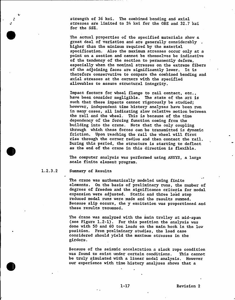
strength of 36 ksi. The combined bending and axialstresses are limited to 24 ksi for the OBE and 32.7 ksifor the SSE.
The actual properties of the specified materials show agreat deal of variation and are generally considerablyhigher than the minimum required by the materialspecification. Also the maximum stresses occur only at apoint on a section and cannot be themselves be indicativeof the tendency of the section to permanently deform,especially when the nominal stresses on the extreme fibersof the adjoining faces are significantly lower. It istherefore conservative to compare the combined bending andaxial stresses at the corners with the specifiedallowables to assure structural integrity.
Impact factors for wheel flange to rail contact, etc.,have been consider negligible. The state of the art issuch that these impacts cannot rigorously be studied;however, independent time history analyses have been runin many cases, all indicating slow relative motion betweenthe rail and the wheel. This is because of the timedependency of the forcing function coming from thebuilding into the crane. Note that the only couplingthrough which these forces can be transmitted is dynamicfriction. Upon reaching the rail the wheel will firstrise through the corner radius and then contact the rail.During this period, the structure is starting to deflectas the end of the crane in this direction is flexible.
The computer analysis was performed using ANSYS, a largescale finite element program.
Summary of Results
The crane was mathematically modeled using finiteelements. On the basis of preliminary runs, the number ofdegrees of freedom and the significance criteria for modalexpansion were adjusted. Static and three load stepreduced modal runs were made and the results summed.Because slip occurs, the y excitation was proportioned andthese results resummed.
The crane was analyzed with the main trolley at mid-span(see Figure 1.2-1). For this position the analysis wasdone with 50 and 60 ton loads on the main hook in the lowposition. From preliminary studies, the load caseconsidered should yield the maximum stresses in thegirders.
Because of the seismic acceleration a slack rope conditionwas found to exist under certain conditions. This cannotbe truly simulated with a linear modal analysis. Howeverour experience with time history analyses shows that a
1-17 Revision 2

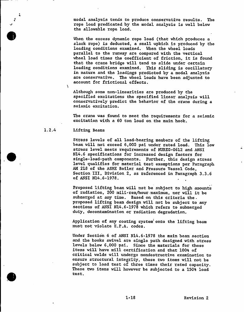
modal analysis tends to produce conservative results. Therope load predicated by the modal analysis is well belowthe allowable rope load.
When the excess dynamic rope load (that which produces aslack rope) is deducted, a small upkick is produced by theloading conditions examined. When the wheel loadsparallel to the runway are compared with the verticalwheel load times the coefficient of friction, it is foundthat the crane bridge will tend to slide under certainloading conditions examined. This sliding is oscillatoryin nature and the loadings predicted by a modal analysisare conservative. The wheel loads have been adjusted toaccount for frictional effects.
Although some non-linearities are produced by thespecified excitations the specified linear analysis willconservatively predict the behavior of the crane during aseismic excitation.
The crane was found to meet the requirements for a seismicexcitation with a 60 ton load on the main hook.
Lifting Beams
Stress levels of all load-bearing members of the liftingbeam will not exceed 6,000 psi under rated load. This lowstress level meets requirements of NUREG-0612 and ANSIN14.6 specifications for increased design factors forsingle-load-path components. Further, this design stresslevel qualifies for material test exemptions per ParagraphAM 218 of the ASME Boiler and Pressure Vessel Code,Section III, Division 2, as referenced in Paragraph 3.3.6of ANSI N14.6-1978.
Proposed lifting beam will not be subject to high amountsof radiation, 200 mili-rem/hour maximum, nor will it besubmerged at any time. Based on this criteria the ~
proposed lifting beam design will not be subject to anysections of ANSI N14.6-1978 which refers to submergedduty, decontamination or radiation degradation.
Application of any coating system onto the lifting beammust not violate E.P.A. codes.
Under Section 6 of ANSI N14 ~ 6-1978 the main beam sectionand the hooks swivel are single path designed with stresslevels below 6,000 psi. Since the materials for theseitems will have mill certification and that 100% ofcritical welds will undergo nondestructive examination toensure structural integrity, these two items will not besubject to load test of three times their rated capacity.These two items will however be subjected to a 1508 loadtest.
1-18 Revision 2
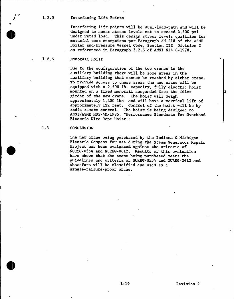
Interfacing Lift Points
Interfacing liftpoints will be dual-load-path and will bedesigned to shear stress levels not to exceed 4,500 psiunder rated load. This design stress levels qualifies formaterial test exemptions per Paragraph AM 218 of the ASMEBoiler and- Pressure Vessel'ode,,Section III, Division 2as referenced in Paragraph 3.2.6 of ANSI N14.6-1978.
Monorail Hoist
Due to the configuration of the two cranes in theauxiliary building there will be some areas in theauxiliary building that cannot be reached by either crane.To provide access to these areas the new crane will beequipped with a 2,500 lb. capacity, fully electric hoistmounted on a fixed monorail suspended from the idlergirder of the new crane. The hoist will weighapproximately 1,200 lbs. and will have a vertical liftofapproximately 122 feet. Control of the hoist will be byradio remote control. The hoist is being designed toANSI/ASME HST-4M-1985, "Performance Standards for OverheadElectric Wire Rope Hoist."
CONCLUSION
The new crane being purchased by the Indiana 6 MichiganElectric Company for use during the Steam Generator RepairProject has been evaluated against the criteria ofNUREG-0554 and NUREG-0612. Results of this evaluationhave shown that the crane being purchased meets theguidelines and criteria of NUREG-0554 and NUREG-0612 andtherefore will be classified and used as asingle-failure-proof crane.
1-19 Revision 2

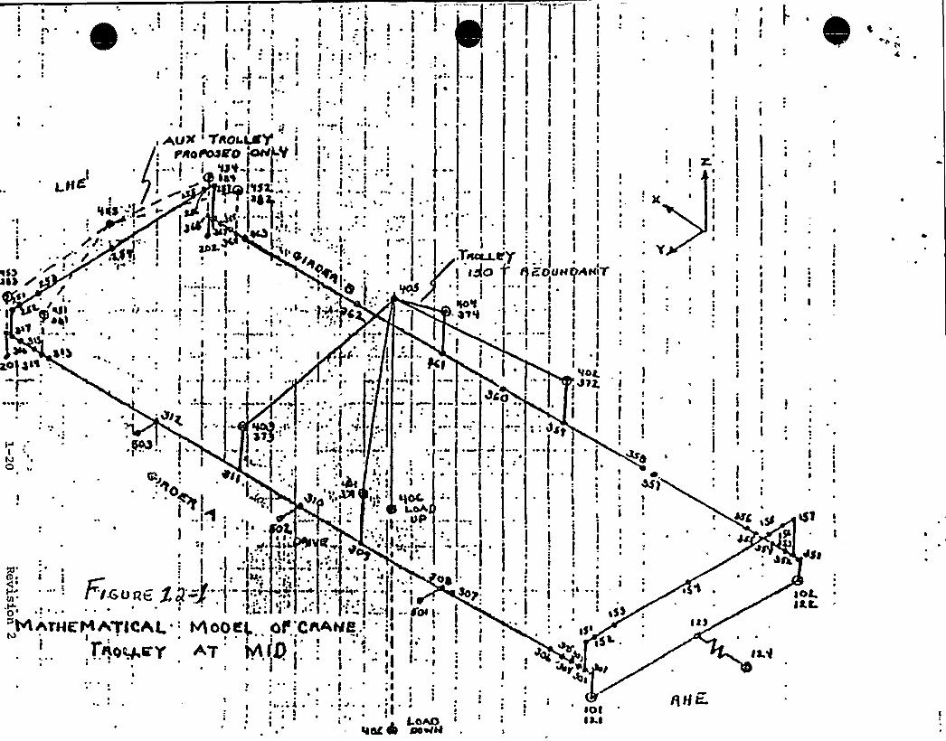
~ II
piggo gN
f~ 'e
I4
~~
II>I'-'f
1 . >>/:~ ~ o / >18~)
~ so44) / /
I ~
-II lan I.i I I
i''
~ ~ ~e
~ I
, A,UX 'AO).LCgr>toto>so Loee >>t
LI - ~ 1 i i '0't-
~ ~I
e
I >1
I." l
I
I
~ . ~
~ ~ I ~~ ~~ ~
l4'0 ]'f4;.
4I '>I~ -:i:
-IIt'"I>-I
- I ~ ~~ I
~ '...'t ". ) . r'.:..'. I .=.l..,'- ':l.
I'
I
I
i~ >~l
',I "I
~~ &~ ~
~~
~I': I" '+1 I . ~
).>ai .o~: I~ ~L"
I~P ~
l, I ~ ~ ~
~ ~ )~
I
QOC
- ~ L)PtI, ~ I . ~
o . apl.fe
I'4c~ et
.II .:
I I4l(le
~ I ~ eg>'
~ ~
~ IIIT~~y ': l
) >go g et-ou~
f)0't~ Q') '4
~ e
pc~ I
~ ~
~ ~ ~
~ II
I
I
i W)I I
I
Vol.I 474.I
I
) ~
I
I
I
~ ~
i~ ~
lI~ ~1
J
III I
AHt"fI
I
tI ~ I
I
~ ~
I
I
I
I III
I
I ~
II
~ I
I
I
I
I jI
Afar y
4A,
4l !
)
~ . I.>~ ]~l~
~' . ~~ >, ~ I. ~
e I
I ' ~,I ~
kl.e.'T
I-rO l.
I
l ~
i .',
~ I - el ~ 1 ~
I ~.I
La~Sac 4h Newel
e
i'HATH@'6ATlCAl.: hhOOag Ot'CaAHR.' s
1o~<Y +7 <l0I
~ ~
IIelt
)5L .
)OI)Ll
)floe'
~ 0 e
Il4~ ~
tLQ
lOtJtC

ATTACHMENT NO. 3 TO AEP:NRC:0894L
iLetter Report MT/SMART-090(89)
D. C. COOK UNIT 2
REACTOR VESSEL HEATUP AND
COOLDOWN LIMIT CURVES FOR NORMAL OPERATION
Apri 1 1989
~~~
~t4-qjil~ ~Z~~1
q ~Jl
C~
C)!- o/WJtel
, ~ LV„VJ
r".. -"=-e .', ~ 1
C 1~ 3
I(
I '~ 1
UJA 0'ii
()L"< r.=
t."J
Prepared by:o o ay
Verified by:
Approved by: 71c 0
eyer, a agerStructural Ma'terials Engineering
Prepared for American Electric Power Company
Although information contained in this report is nonproprietary, nodistribution shall be made outside Westinghouse or its licensees without thecustomer's approval.
WESTINGHOUSE ELECTRIC CORPORATIONNuclear and Advanced Technology Division
P.O. Box 2728Pittsburgh, Pennsylvania 15230-2728
3716s/0421N:10
ATTACHMENT NO. 3
TO
AEP: NRC: 0894L

1g
0

TABLE OF CONTENTS
Section Ti tie Page
1.0
2.0
3.0
INTRODUCTION
FRACTURE TOUGHNESS PROPERTIES
'ADJUSTED REFERENCE TEMPERATURE
4.0 CRITERIA FOR ALLOWABLE PRESSURE-TEMPERATURE RELATIONSHIPS 3
5.0
6.0
HEATUP AND COOLDOWN LIMIT CURVES
REFERENCES
APPENDIX A HEATUP AND COOLDOWN DATA - WITHOUT MARGINS FOR
INSTRUMENTATION ERROR
A-1
APPENDIX B HEATUP AND COOLDOWN DATA - WITH MARGINS FOR
INSTRUMENTATION ERROR
B-1
37lds/0427dQ:10

IPt
LIST OF TABLES
Table Title Page
D. C. Cook Unit 2 Reactor Vessel Fracture Toughness
Properties
Calculation of Adjusted Reference Temperatures for Limiting0. C. Cook Unit 2 Reactor Vessel Material - IntermediateShell Plate - C5556-2
10
Calculation of Adjusted Reference Temperatures for0. C. Cook Unit 2 Reactor Vessel Material - IntermediateShell Plate - C5521-2
LIST OF FIGURES
Figure
1
Ti tie
Fluence Factor for Use in the Expression for ARTNDT
Page
12
D. C. Cook Unit 2 Reactor Coolant System HeatupLimitations Applicable for the First 12 EFPY
(Without Margins)
13
0. C. Cook Unit 2 Reactor Coolant System Cooldown
Limitations Applicable for the First 12 EFPY
(Without Margins)
14
D. C. Cook Unit 2 Reactor Coolant System HeatupLimitations Applicable for the First 32 EFPY
(Without Margins)
15
0. C. Cook Unit 2 Reactor Coolant System Cooldown
Limitations Applicable for the First 32 EFPY
(Without Margins)
37)6@/Oi2760:10 ill
~ ( ~
LIST OF FIGURES (cont)
I
Figure Ti tle Page
D. C. Cook Unit 2 Reactor Coolant System Heatup
Limitations Applicable for the First 12 EFPY
(With Margins)
'7D. C. Cook Unit 2 Reactor Coolant System Cooldown
Limitations Applicable for the First 12 EFPY
(With Margins)
18
D. C. Cook Unit 2 Reactor Coolant System Heatup
Limitations Applicable for the First 32 EFPY
(With Margins)
19
D. C. Cook Unit 2 Reactor Coolant System Cooldown
Limitations Applicable for the First 32 EFPY
(With Margins)
20
,3716e/041169:10 iv

1
P
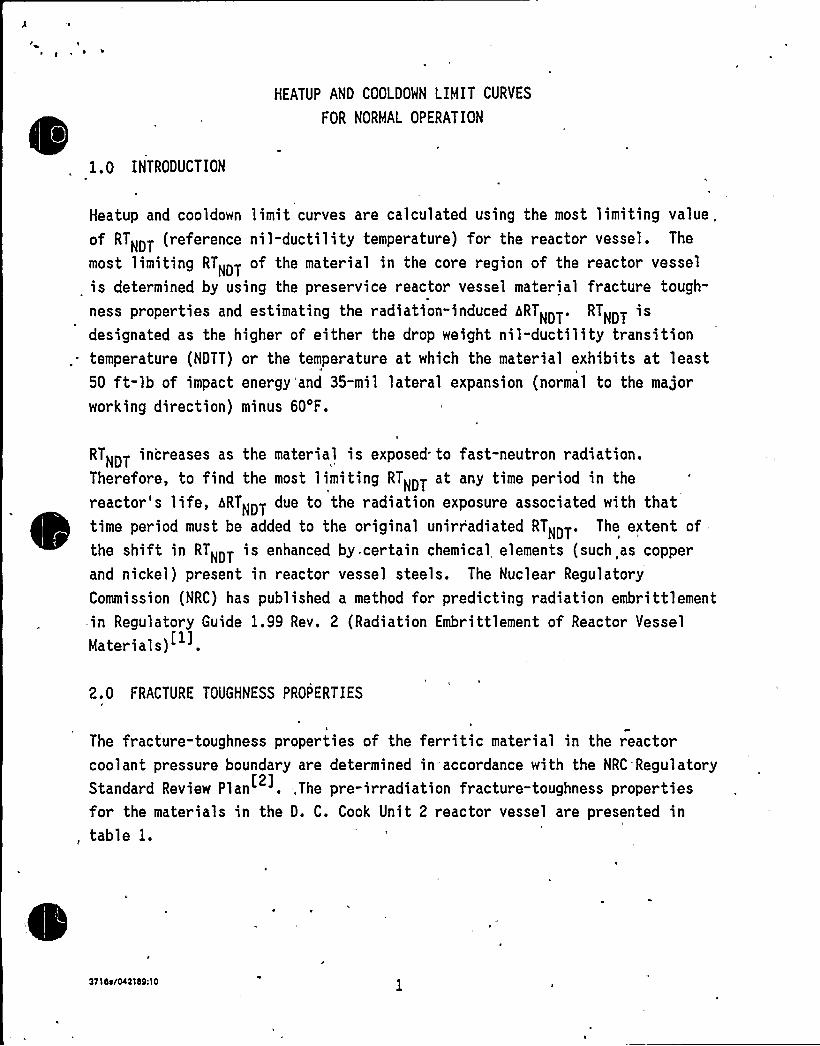
HEATUP AND COOLDOWN LIMIT CURVES
FOR NORMA OPERATION
1. 0 INTRODUCTION
Heatup and cooldown limit curves are calculated using the most limiting value.of RTNDT (reference nil-ductility temperature) for the reactor vessel. The
most limiting RTNDT of the material in the core region of the reactor vessel
is determined by using the preservice reactor vessel material fracture tough-
ness properties and estimating the radiation-induced hRTNDT. RTNDT isdesignated as the higher of either the drop weight nil-ductility transition
.. temperature (NDTT) or the temperature at which the material exhibits at leasttt t
50 ft-lb of impact energy'and 35-mil lateral expansion (normal to the majorworking direction) minus 60'F.
RTNDT increases as the material i s exposed to fast-neutron radi ation.Therefore, to find the most limiting RTNDT at any time period in the
reactor's life, hRTNDT due to the radiation exposure associated with that~
~
~
~
~
time period must be added to the original unirradiated RTNDT. The extent ofthe shift in RTNDT is enhanced by, certain chemical elements (such as copperand nickel) present in reactor vessel steels. The Nuclear RegulatoryCommission (NRC) has published a method for predicting radiation embrittlementin Regulatory Guide 1.99 Rev. 2 (Radiation Embrittlement of Reactor Vessel
Materials)~
2.0 FRACTURE TOUGHNESS PROPERTIES
t
The fracture-toughness properties of the ferritic material in the reactorcoolant pressure boundary are determined in accordance with the NRC'Regulatory
Standard Review Plan . ,The pre-irradiation fracture-toughness propertiesfor the materials in the D. C. Cook Unit 2 reactor vessel are presented in
, table 1.
37'I es/0421bQ:10

From Regulatory Guide 1.99 Rev. 2 [1] the adjusted reference temperature (ART)
for each material in the beltline is given by the following expression:
ART = Initial RTNDT+ ~RTNDT + M rg'n
Initial RTNDT is the reference temperature for the unirradiated material as
defined in paragraph NB-2331 of Section III of the ASME Boiler and Pressure
Vessel Code. If measured values of initial RTNDT for the material in
question are not available, generic mean values for that class of material may
~be used if there are sufficient test results to establish a mean and standard
deviation for the class.
hRTNDT is the mean val ue of the adjustment in reference temperature caused
by irradiation and should be-calculated as follows:
[CF]f(0. 28-0 ~ 10 1 og f) [CF] [ff]NDT
(2)
The value, "f", used in equation (2) is the calculated value of the neutron
fluence at the location in the vessel at the location of the postulated
defect, n/cm (E > 1 MeV) divided by 10 , The fluence factor, "ff" isshown in figure 1.
To calculate bRTNDT at any depth (e.g., at 1/4T or 3/4T), the following
formula must first be used to attenuate the fluence at the specific depth.
-,24x(depth X) surface (3)
where x (in inches) is the depth into the vessel wall measured from the vessel
inner (wetted) surface. The attenuated fluence is then used in equation (2)
to calculate hRTNDT at the specific depth.
~
~
CF ('F) is the chemistry factor, obtained from reference 1 for the beltlineregion materials of the D. C. Cook Unit 2 reactor pressure vessel. The
3716s/042160:10
limiting material was found to be the intermediate shell plate C5556-2 for 0.C. Cook Unit 2 for 12 EFPY and 32 EFPY. The calculation of ART for thislimiting material is shown in table 2. The ART values at 1/4T and 3/4Tlocations will be used to develop the reactor pressure vessel heatup and
cooldown curves as described in the following sections.
4.0 CRITERIA FOR ALLOWABLE PRESSURE-TEMPERATURE RELATIONSHIPS
The ASME approach for calculating the allowable limit curves for variousheatup and cooldown rates specifies that the total stress intensity factor,KI, for the combined thermal and pressure stresses at any time during heatupor cooldown cannot be greater than the reference stress intensity factor,KIR, for the metal temperature at that time. KIR is obtained from thereference fracture toughness curve, defined in Appendix G to the ASME Code
The KIR curve is given by the following eqqation:
KIR= 26.78 + 1.223 exp [0.0145 (T-RTNDT" + 160)] (4)
where
KIR= reference stress intensity factor as a function of the metal
temperature T and the metal reference nil-ductility temperature RTNDT*P
Therefore, the governing equation for the heatup-cooldown analysis is definedin Appendix G of the ASME Code ] as follows:
(5)
*NOTE: RTN>T as used in the ASME Code [3] is in fact the adjusted referencetemperature (ART) as defined in NRC Regulatory Guide 1.99, Rev. 2 [1]and calculated in section 3.0.
371bs/Oi2189:l0

f4

where
K>M= stress intensi-ty factor caused by membrane (pressure) stress
K>T= stress intensity factor caused by the thermal gradients
K>R= function of temperature relative to the RTNDT of the material
C = 2.0 for Level A and Level B service limits
C = 1.5 for hydrostatic and leak test conditions during which the reactorcore is not critical
At any time during the heatup or cooldown transient, K>R'is determined by
the metal temperature at the tip of 'the postulated flaw, the appropriate value
for RTNDT, and the reference fracture toughness curve. The thermal stresses
resulting from the temperature gradients through the vessel wall are calcu-lated'and then the corresponding (thermal) stress intensity factors, K<T,for the reference flaw are computed. From equation (5), the pressure stressintensity factors are obtained and, from these, the allowable pressures are
ca 1 cul ated.
For the calculation of the allowable pressure ver'sus coolant temperature
during cooldo'wn, the reference flaw of Appendix G to the ASME Code [3] isassumed to exist at the inside of the vessel wall. During cooldown, the
controlling location of the flaw is always at the inside of the wall, because
the thermal gradients produce tensile stresses at the inside, which increasewith increasing cooldown r ates. Allowable pressure-temperature relations are
generated for both steady-state and finite cooldown. rate situations. From
these relations, composite limit curves are constructed for each cooldown rateof interest.
The use of the composite curve in the cooldown analysis is necessary because
control of the cooldown procedure is based on the measurement of reactorcoolant temperature, whereas the limiting pressure is actually dependent on
the material temperature at the tip of the assumed flaw.
37 l6s/Oi21d9: lO

, VfyI,
jY
'1
'4
>5 '"0'
ir>
pI
During cooldown, the 1/4 T vessel location is at a higher temperature than the
fluid adjacent t'o the vessel inside surface. This condition, of course, isnot true for the steady->tate situation. It follows that, at any given
reactor coolant temperature, the AT developed during cooldown results in a
higher value of KIR at the 1/4 T location for finite cooldown rates than forsteady-state operation. Furthermore, if conditions exist so that the incr ease
in KIR exceeds KIT, the calculated allowable pressure during cooldown willbe greater than the steady-state value.
The above procedures are needed because there is no direct control on
temperature at the 1/4 T location and, therefore, allowable pressures may
unknowingly be violated if the rate of cooling is decreased at variousintervals along a cooldown ramp. The use of the composite curve eliminatesthis problem and ensures conservative operation of the system for the entirecooldown period.
Three separate calculations are required to determine the limit curves forfinite heatup rates. As is done in the cooldown analysis, allowable pressure-temperature relationships are developed for steady-state conditions as well as
finite heatup rate conditions assuming the presence of a 1/4 T defect at the
inside of the wall that alleviate the tensile stresses produced by internalpressure. The metal temperature at the crack tip lags the coolanttemperature; therefore, the KIR for the 1/4 T crack during heatup is lower
than the KIR for the 1/4 T crack during steady-state conditions at the same
coolant temperature. During heatup, especially at the end of the transient,conditions may exist so that the effects of compressive thermal stresses and
lower KIR's do not offset each other, and the pressure-temperature curve
based on steady-state conditions no longer represents q lower bound of allsimilar curves for finite heatup rates when the 1/4 T flaw is considered.Therefore, both cases have to be analyzed in order to ensure that at any
coolant temperature the lower value of the allowable pressure calculated forsteady-state and finite heatup rates is obtained.
The second portion of the heatup analysis concerns the calculation of thepressure-temperature limitations for the case in which a 1/4 T deep outside
3710s/Oll 169:l0

t
I
'
ri
I
surface flaw is assumed. Unlike the situation at the vessel inside surface,the thermal gradients established at the outside surface during heatup produce
stresses which are tensile in nature and therefore tend to reinforce any
pressure stresses present. These thermal stresses are dependent on both the
rate of heatup and the time (or coolan't temperature') along the heatup ramp.
Since the thermal stresses at the outside are tensile and increase withincreasing heatup rates, each heatup rate, must be analyzed on an individualbasis.
Following the generation of pressure-temperature curves for both the steady-state and finite heatup rate situations, the final limit curves are produced
by constructing a composite curve based on a point-by-point comparison of thesteady-state and finite heatup rate data. At any given temperature, theallowable pressure is taken to be the lesser of the three values taken fromthe curves under consideration. The use of the composite curve is necessary
to set conservative heatup limitations because it is possible for conditionsto exist wherein, over the course of the heatup ramp, the controllingcondition switches from the inside to the outside, and the pressure limit must
at all times be based on analysis of the most critical criterion.
Finally, the 1983 Amendment to lOCFR50 has a rule which addresses themetal temperature of the closure head flange and vessel flange regions. Thisrule states that the metal temperature of the closure flange regions must
exceed the material RTNpT by at least 120'F for normal operation when the
pressure exceeds 20 percent of the preservice hydrostatic test pressure.
5.0 HEATUP AND COOLOOWN LIMIT CURVES
Limit curves for normal heatup and cooldown of the primary Reactor Coolant
System have been calculated using the methods described in section 4.0, and
the Westinghouse procedure of reference 5.
Allowable combinations of temperature and pressure for specific temperature
change rates are below and to the right of the limit lines shown in figures 2
3, 6 and 7 for 12,EFPY and in figures 4, 5, 8 and 9 for 32 EFPY. Figures 2
~ ~
~ ~
~
~
~
~
~
through 5 do not have any margins for instrumentation error and figures 6f
through 9 contain margins for instrumentation error. This is in addition toother criteria which must be met before the reactor is made critical.
The leak limit curve shown in figures 2, 4, 6 and 8 represent the minimum
temperature requirements at the leak test pressure specified by applicablecodes ' The leak test limit curves were determined by the methods ofreferences 2 and 4.
Finally, table 1 indicates that the limiting flange RTNDT of 30'F occurs inthe vessel flange so the minimum allowable temperature of this region is 150'F
per reference 4. These limits are less restrictive than the limits shown on
figures 2 through 9.
Figures 2 through 9 define the limits for ensuring prevention of nonducti lefailure for the D. C. Cook Unit 2 Primary Reactor Coolant System.
6.0 REFERENCES
1. Regulatory Guide 1.99, Revision 2, "Radiation Embrittlement of ReactorVessel Materials," U.S. Nuclear Regulatory Commission, May, 1988.
2. "Fracture Toughness Requirements," Branch Technical Position MTEB 5-2,Chapter 5.3.2 in Standard Review Plan for the Review of Safety AnalysisReports for Nuclear Power Plants, LWR Edition, NUREG-0800, 1981.
3. ASME Boiler and Pressure Vessel Code, Section III, Division 1-Appendixes, "Rules for Construction of Nuclear Power Plant Components,
Appendix G, Protection Against Nonducti le Failure," pp. 558-563, 1986
Edition, American Society of Mechanical Engineers, New York, 1986.
4. Code of Federal Regulations, 10CFR50, Appendix G, "Fracture Toughness
Requirements," U.S. Nuclear Regulatory Commission, Washington, D.C.,Federal Register, Vol. 48 No. 104, May 27, 1983.
371St/Ol2760:10
5. "Procedure for Developing Heatup and Cooldown Curves," Westinghouse
Electric Cor'poration, Generation Technology Systems Division Procedure
GTSO-A-1.12 (Rev. 0)., July 13, 1988.
6. "Assessment of Regulatory Guide 1.99, Revision 2 Upon D. C. Cook Units 1
and 2 Adjusted Reference Temperatures and Pressure-Temperature Curves"
SWRI Project 17-2544.
3716s/04216Q:10

TABLE 1
D. C. COOK UNIT 2 REACTOR VESSEL TOUGHNESS PROPERTIES (UHIRRADIATED)
Component Code Ho. Material Type Cu
50 ft-lb35 Hil
T Temp(a)HDT
( F) ( F)
USE
RTNDT $$ NHWD(a)
( F) (ft-lb) (ft-tb)0
Closure Head Dome
Closure Head Segment
Closure Head Segment
Closure Head Flange
Vessel Flange
Inlet Nozzle
Inlet Hozzle
Inlet Nozzle
Inlet NozzleOutlet Nozzle
Outlet Nozzle
Outlet Nozzle
Outlet Nozzle
Upper ShellUpper ShellUpper ShellInter. ShellInter Shell.
Lower ShellLower ShellBottom Head Segment
Bottom Head Segment
Bottom Head Dome
Inter. 8 Lower
Shell Long. and
Girth Held Seam
80048-2
89M3-2A5189-2
4437-V-1
4436-V-2269T-2
270T-1
269T-1
270T-2
271T-1
271T-2
272T-1
272T-2
C5518-2
C5521-1
C5518-1
C5556-2
C5521-2
C5540-2
C5592-1
C5823-2
A4957-3
B0018-18
(HT S3986 8
Linde 124
Flux LotNo. 0934)
A533B Cl. 1
A533B CI. 1
A533B Cl. 1
A508 Cl ~ 2
A508 Cl. 2
A508 Cl. 2
A508 Cl. 2
A508 CI. 2
A508 Cl. 2
A508 Cl. 2
A508 Cl. 2
A508 Cl. 2
A508 Cl ~ 2
A533B Cl. 1
A533B CI. 1
A533B CI. 1
A533B CI. 1
A533B CI. 1
A533B Cl. 1 ~
A533B Cl. 1
A5338 Cl. 1
A5338 CI. 1
A533B CI. 1
SAH
NA 0.64 -20
HA 0.66 -20
NA 0.63 10
HA 0.70 -20
NA 0.70 30
NA 0.85 -20
HA 0.9l -20
HA HA -'IO
HA HA -10
NA 0.80 0
NA 0.80 0
NA NA -10
NA HA 0
0.12 0.61 10
0.14 0.59 0
0.12 0.57 10
0.15 0.57 0
0.14 0.58 10
0.11 0.64 -20
0.14 0.59 -20
NA 0.57 -10
NA 0.51 -10
NA 0.61 -50
0.06 0.97 -40
30-372
5
15
-15- 3
NA
NA
12
-15
NA
NA
88
93
66
118(b)98(b)35(b)25(b)45
20
9
25
-20-20
12
-20
30-20-20-10.-10
0
0-'IO
0
28
33
10
58(b)38(b)
„-20(b)-20(b)-10-10-50
-35(b)
148
143.5
140.5
239
161
201 ~ 5
239.5NA
HA
>179
181
HA
NA
107.5
112
> 82.5109.5
111.5
113
107
129
149
177
NA
96
93
91
155
105
131
156
HA
HA
NA
117.5
NA
NA
70
73
HA
90(b)86(b)
110(b)103(b)84
97
115
97(b)
Plan
as appropriate
a) Estimated per NRC Standard Review
b) Actual valuesHA - Hot available or not applicable,
KWD - Hajor Working DirectionNHWD - Normal to NMD

~ fC '
fAll
I
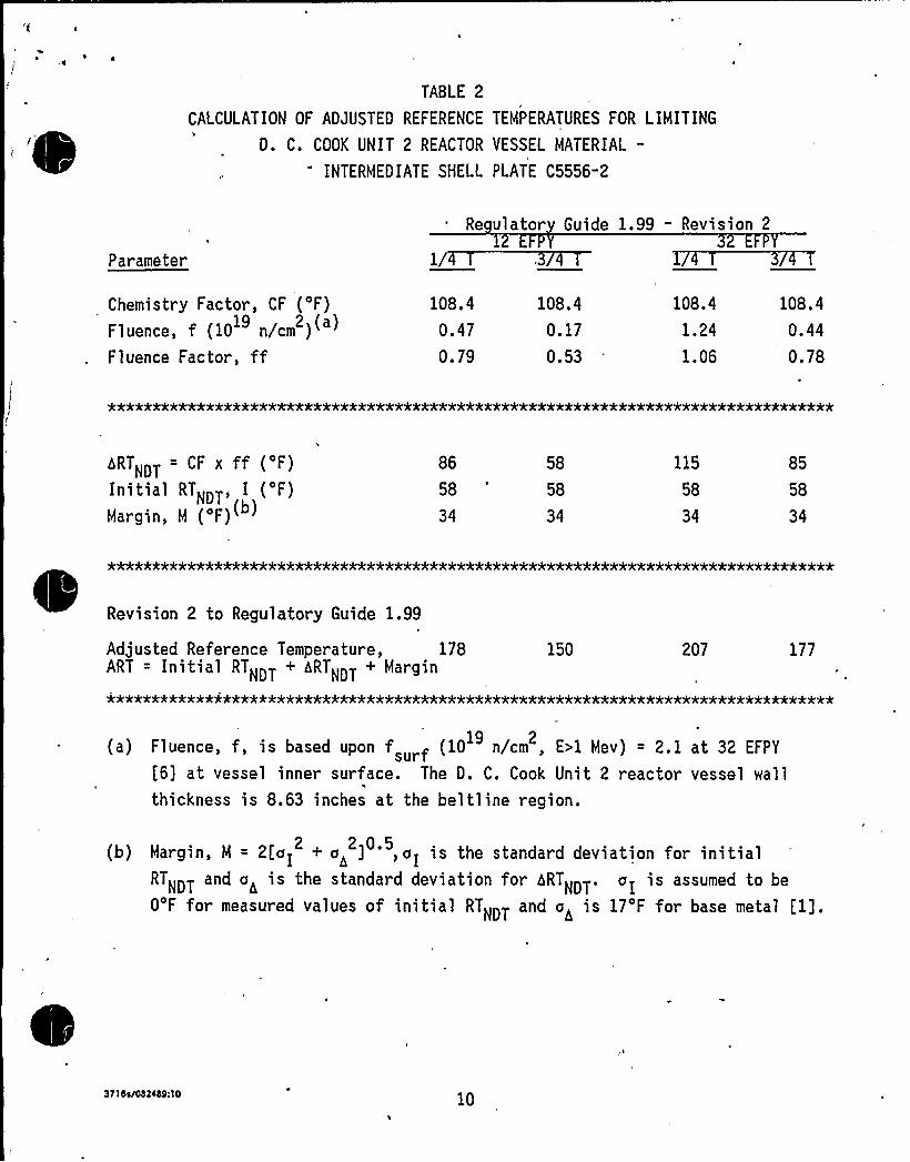
'TABLE 2
CALCULATION OF ADJUSTED REFERENCE TEMPERATURES FOR LIMITING
D. C. COOK UNIT 2 REACTOR VESSEL MATERIAL-
INTERMEDIATE SHELL PLATE C5556-2
Parameter
Re ulator Guide 1.99 - Revision 2
Chemistry Factor, CF ('F)Fluence, f (10 n/cm )
19 2 a
Fluence Factor, ff
108.4
0.47
0.79
. 108.4
0.17
0.53
108.4
1.24
1.06
108.4
0.44
0.78
~RTNDT CF x ff ( F)
Initial RTNDT, I ('F)Margin, M ('F)
86
58
34
58
58
34
115
58
34
85
58
34
*******************************************k'k********)t'k*'k***4**5t'kk'k)kAk'kk%'********
Revision 2 to Regulatory Guide 1.99
Adjusted Reference Temperature, 178ART = Initial RTNDT + ARTNDT + Margin
150 207 177
(a) Fluence, f, is based uPon fsurf (10 n/cm , E)1 Mev) = 2.1 at 32 EFPY19
[6] at vessel inner surface. The D. C. Cook Unit 2 reactor vessel wallthickness is 8.63 inches at the bel tl inc region.
(b) Margin, M = 2[vI + a> ] ', oI is the standard deviation for initial2 2 0.5
RTNDT and a< is the standard deviation for ARTNDT. aI is assumed to be
O'F for measured values of initial RTNDT and o< is 17'F for base metal [1].
3715s/082ib9:10 10

~ \
tk-
pVi
fr
4
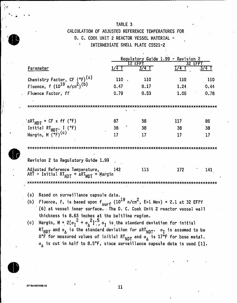
TABLE 3
CALCULATION OF ADJUSTED REFERENCE TEMPERATURES FOR
D. C. COOK UNIT 2 REACTOR VESSEL MATERIAL-
INTERMEDIATE SHELL PLATE C5521-2
Parameter
Re ulator Guide 1.99 - Revision 2
Chemistry Factor, CF ('F)Fluence, f (10 n/cm )
19 2 b
Fluence Factor, ff
110
0.47
0.79
110
0.17
0.53
110
1.24
1.06
110
0.44
0.78
hRTNDT CF x ff ( F)
Initial RTNDT, I ('F)Margin, M ('F)
87
38
17
58
38
17
117
38
17
86
38
17
*************************)tk**********'O'Jt'****4k***A****'k'kkk*******'k**k*************
Revision 2 to Regulatory Guide 1.99
Adjusted Reference Temperature, 142ART = Initial RTNDT + ARTNDT + Margin
113 172 141
(a) Based on surveillance capsule data.
(b) Fluence, f, is based upon f urf (10 n/cm , E>1 Mev) = 2. 1 at 32 EFPY
'6] at vessel inner surface. The D. C. Cook Unit 2 reactor vessel wallthickness is 8.63 inches at the beltline region.
(c) Margin, M = 2[ol + o< ]', aI is the standard deviation for initial2 2.5
RTNDTand a< i s the standard devi at ion for b RTNDT ~ a I i s assumed to be
O'F for measured values of initial RTNDT and a< is 17'F for base metal.
a< is cut=in half to 8.5'F, since surveillance capsule data is used [1].
371St/082i69:10
1
h
W
i4
PI.
I
N V
t
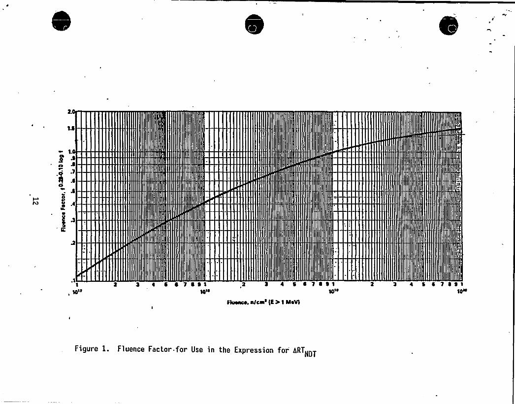
IIII
~ R illI illlIIIRIIRIIIIIIIIIIiiiIIIIIhllll
llllllllIIIIIII
II IIIII>
I~Iiil
IIII
«reII
IIII
I
P,
t '
Il
gfr
I
l
Ql
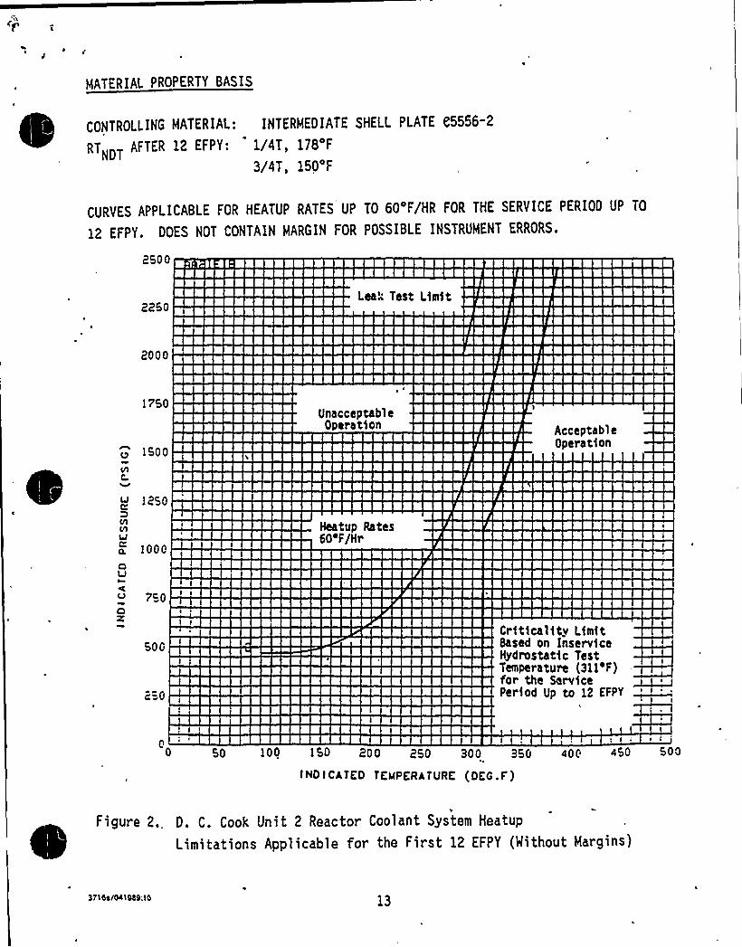
o
MATERIAL PROPERTY BASIS
CONTROLLING MATERIAL: INTERMEDIATE SHELL PLATE C5556-2
RTNDT AFTER 12 EFPY: 1/4T, 178'F
3/4T, 150'F
CURYES APPLICABLE FOR HEATUP RATES UP TO 60'F/HR FOR THE SERYICE PERIOD UP TO
12 EFPY, DOES NOT CONTAIN MARGIN FOR POSSIBLE INSTRUMENT ERRORS.
2500
2250Lea'est Lim)t
2000
1750
1500
UnacceptableOperation Acceptable
Operation
1250
a. 100 0
4VI
7c04Z
o
500
250
HeatIIp Rates60'F/Hr
Criticality LimitBased on InserviceHydrostat)c TestTemperature (311 F)for the Service I
poHod Up oo 12 EppYL
050 100 150 200 250 300 350 400 450
INDICATED TEMPERATURE (DEC.F)
o~
~
~ ~
~Figure 2. D. C Cook Unit 2 Reactor Coolant System Heatup
Limitations Applicable for the First 12 EFPY (Without Margins)
3T10ss041089.10 13
A
(p
f
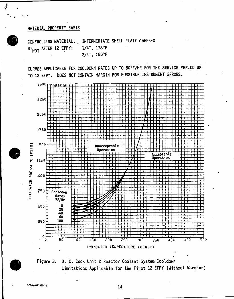
MATERIAL PROPERTY BASIS
CONTROLLING MATERIAL: INTERMEDIATE SHELL PLATE C5556"2
RTNDT AFTER 12 EFPY 1/4T 178 F
3/4T, 150'F
CURVES APPLICABLE FOR COOLOOWN RATES UP TO 60'F/HR FOR THE SERVICE PERIOD UP
TO 12 EFPY. DOES NOT CONTAIN MARGIN FOR POSSIBLE INSTRUMENT ERRORS.
2500
2250
200G
1750
~00
f2=0
C1LJ
n. I 000
UnacceptableOperation
Acceptab'leOperation
I ~
Cool CownRatesF/Hr
020
~ 4060
l00
( a S ~ a
I ~C
50 100
s I I I ~
5'04GG
I I ~
I 50 200 250 "OG 25G
INDICATED TEMPERATURE (DEC.F')
Figure 3. D. C. Cook Unit 2 Reactor Coolant System Cooldown
Limitations Applicable for the First 12 EFPY (Without Margins)
3110j/Oi)N9:10
C
I
P„
~ I
P «
t
i'g x
'4'
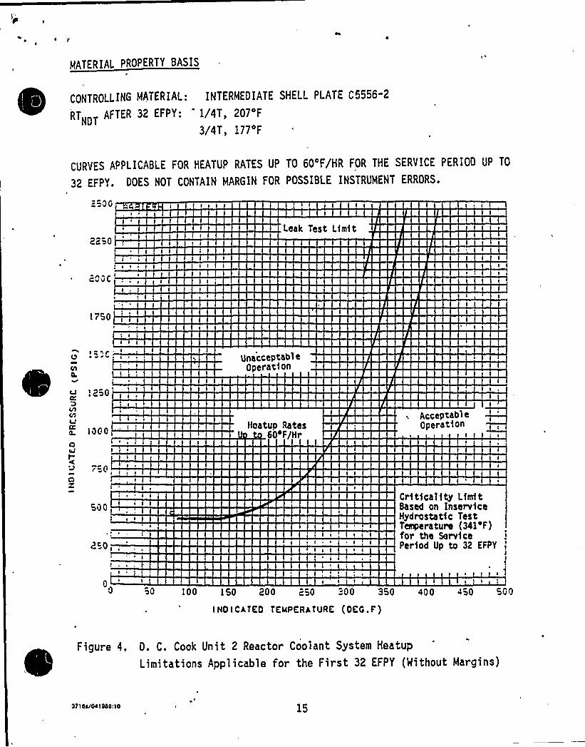
MATERIAL PROPERTY BASIS
CONTROLLING MATERIAL: INTERMEDIATE SHELL PLATE C5556"2
RTNDT AFTER 32 EFPY: 1/4T, 207'F
3/4T, 177'F
CURVES APPLICABLE FOR HEATUP RATES UP TO 60'F/HR FOR THE SERVICE PERIOD UP TO
32 EFPY. DOES NOT CONTAIN MARGIN FOR POSSIBLE INSTRUMENT ERRORS.
"OG
2250Leak Test Limit
20GC
I750
Q ~av unacceptab1eOperation
I2~0
Ill iC1V0 I000CIuJ
Clz
500
250,,
Hoatuo Rates00F/Hr
~ i ~ + I I
I I I
Acceptab>eOperation
Critica1$ ty LimitBased on InservfceHydrostat)c TestTenperature (341'F)for the Service IPeriod Up to 32 EFPY I
0 I i I
50 l00 150 200 250 300 350 400 450 500
INOICATEO TEllPERATURE (OEG.F)
~
~
~
~
~
~
Figure 4. D. C. Cook Unit 2 Reactor Coolant System Heatup
Limitations Applicable for the First 32 EFPY (Mithout Margins)
3710e/041000; l0 15
'I
wrWI
l~
'k
I.?
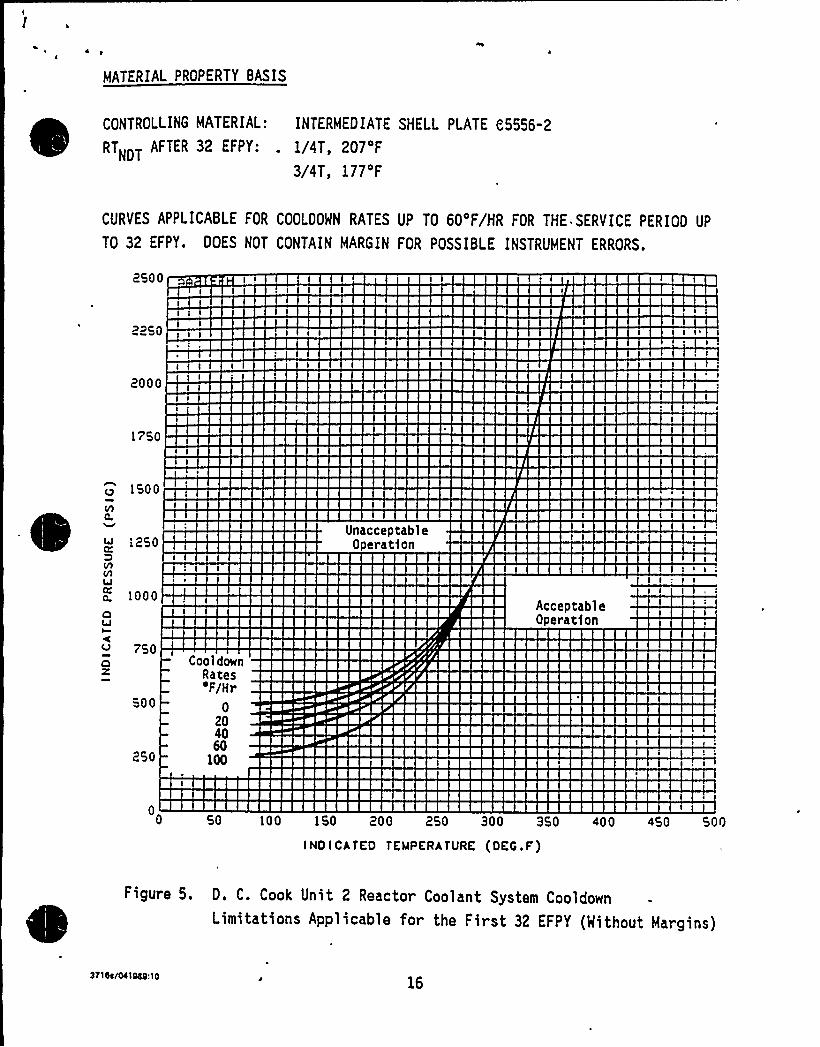
MATERIAL PROPERTY BASIS
CONTROLLING MATERIAL: INTERMEDIATE SHELL PLATE e5556-2
RTNDT AFTER 32 EFPY: . 1/4T, 207'F
3/4T, 177'F
CURVES APPLICABLE FOR COOLDOMN RATES UP TO 60'F/HR FOR THE. SERVICE PERIOD UP
TO 32 EFPY. DOES NOT CONTAIN MARGIN FOR POSSIBLE INSTRUMENT ERRORS.
2500
2250
2000
1750
1500
1250UnacceptableOperatfon
a. 1000QtJI
750Oz
500
250
CooldownRaces'F/Hr
0204060
100
AcceptableOperatfon
050 100 150 200 250 300 350 400 450 500
INOICATKO TEMPERATURE (OEG.F')
Figure 5. D. C. Cook Unit 2 Reactor Coolant System CooldownLimitations Applicable for the First 32 EFPY (Nithout Margins)
311'/MIN10
\
C~
4
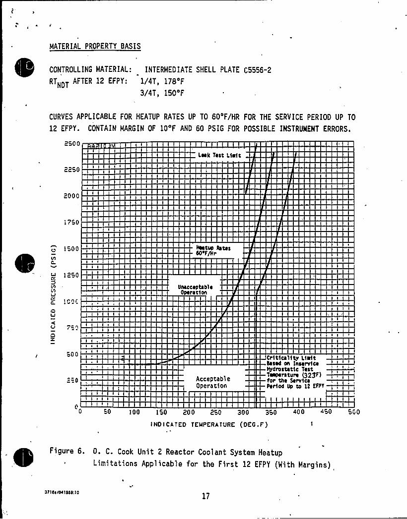
MATERIAL PROPERTY BASIS
CONTROLLING MATERIAL: INTERMEDIATE SHELL PLATE C5556-2~
~RTNDT AFTER 12 EFPY: 1/4T, 178'F
3/4T, 150'F
CURVES APPLICABLE FOR HEATUP RATES UP TO 60'F/HR FOR THE SERVICE PERIOD UP TO
12 EFPY. CONTAIN MARGIN OF 10'F AND 60 PSIG FOR POSSIBLE INSTRlNENT ERRORS.
2500
Leek Test Limit
2250
2000
1750
1500 IIeetup IotasNef~r
lhLJ
10hl
OLJI
O
s ~
s s ~ 1
s . I 1 I
Unacceptabl ~0 ration
500
2=0 AcceptableOperation
baaed on Insane casrerestet14 TestT~rstere 529F)for the ServiceFertee Ue te 12 EFFT~
50 100 150 200 25p 3pp 35p 400 450 5„p
INDICATED TEMPERATURE (DEG.F')
Figure 6. D. C. Cook Unit 2 Reactor Coolant System Heatup~
~
Limitations Applicable for the First 12 EFPY (With Margins)
3z>asiocisasno17
(4
W I
I 't
IP
1
AWL
~ I
n
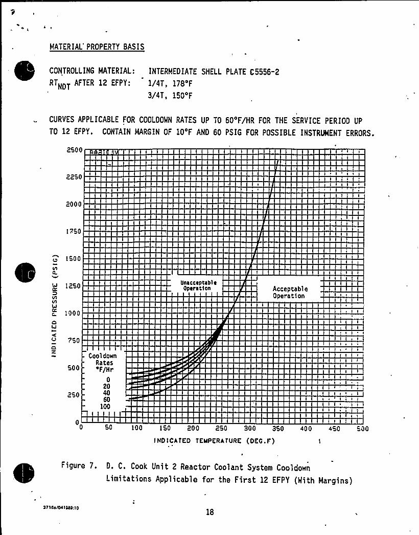
MATERIAL'ROPERTY BASIS
CONTROLLING MATERIAL: INTERMEDIATE SHELL PLATE C 5556-2
RTNDT AFTER 12 EFPY 1/4T 178 F
3/4T, 150'F
CURVES APPLICABLE FOR COOLDOWN RATES UP TO 60'F/HR FOR THE SERVICE PERIOD UP
TO 12 EFPY. CONTAIN MARGIN OF 10'F AND 60 PSIG FOR POSSIBLE INSTRUMENT ERRORS.
2500
2250
2000
1750
w 1250
1000OI
750
Z
500
250
CooldownRates'F/Hr
0204060
100
UnaccaptablaOparat1on Acceptable
Operation
I
I I
I s i
I s > v'
5 I
05P 100 150 200 250 300 350 400 450 50P
INDICATED TEMPERATURE (OEG.F)
0
Figure 7. D. C, Cook Unit 2 Reactor Coolant System CooldownLimitations Applicable for the First 12 EFPY (With Margins)
371 di/0410aa:1018
«1~4
4r
4 ~
Il
I1
.1
t%%
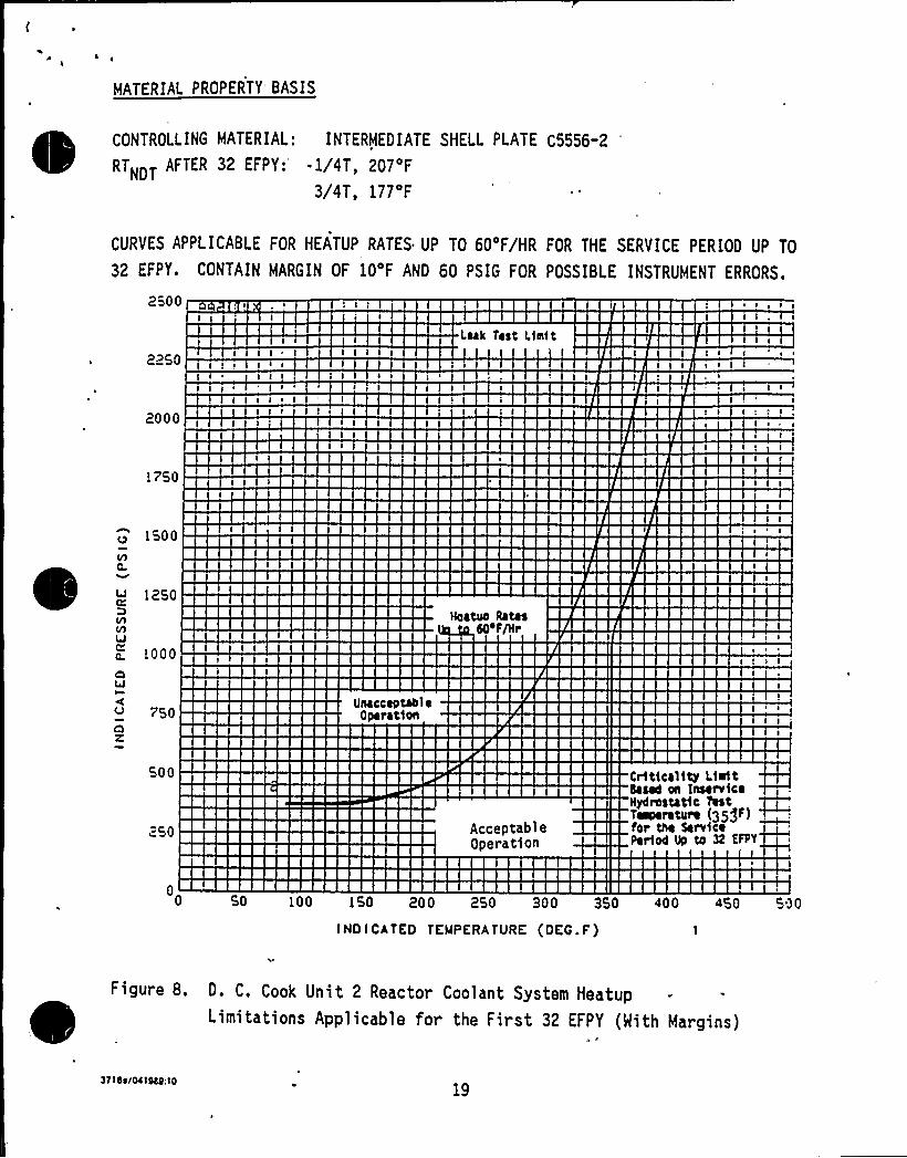
I~I
MATERIAL PROPERTY" BASIS
CONTROLLING MATERIAL: INTERMEDIATE SHELL PLATE C5556-2
RTNDT AFTER 32 EFPY: - 1/4T, 207'F
3/4T, 177'F
CURVES APPLICABLE FOR HEATUP RATES UP TO 60'F/HR FOR THE SERVICE PERIOD UP TO
32 EFPY. CONTAIN MARGIN OF 10'F AND 60 PSIG FOR POSSIBLE INSTRUMENT ERRORS.
2500 8
Leak Test Limit
2250
I I
2000I
I I s
~ I
!750
1500
Vl
! 250
a. ! 000OI
750OZ
Unacceotaol eOperation
50~ F/Hr
500
250 AcceptableOperation
Criticality LicitIaaee on lnaerviceHy4roatatic TeatTWwreture (35)~) ~for the ServiceZrioe up to 3Z ER'T
0 50 100 150 200 250 300 350 400 450 500
INOICATEO TEMPERATURE (OEG.F)
Figure 8. D. C, Cook Unit 2 Reactor Coolant System HeatupLimitations App1icab1e for the First 32 EFPY (Mith Margins)
371as/043040:1019

i)
Ol
P
1J
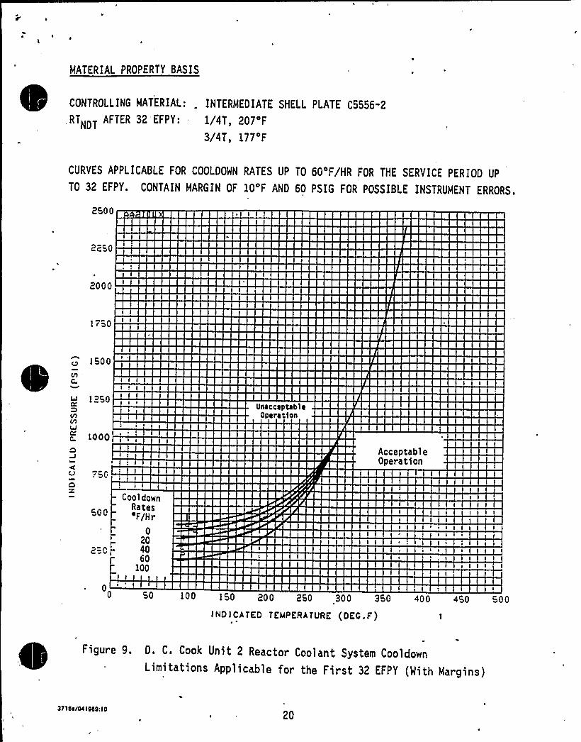
MATERIAL PROPERTY BASIS
CONTROLLING MATERIAL: . INTERMEDIATE SHELL PLATE C5556-2
, RTNDT AFTER 32 'FPY ' 1/4T 207 F
3/4T, 177'F
CURVES APPLICABLE FOR COOLDOWN RATES UP TO 60'F/HR FOR THE SERVICE PERIOD UP
TO 32 EFPY. CONTAIN MARGIN OF 10'F AND 60 PSIG FOR POSSIBLE INSTRUMENT ERRORS.
2500
2250
2000
1750
1250
L000
UnacceptableOperatIon
AcceptableOperation
500
I
2= C',"
~ 0
CooldownRates'F/Hr
0204060
100I I
I
50 100 150 200 250 300 3
INDICATED TEMPERATURE (OEG ~ F)
Figure 9. D. C. Cook Unit 2 Reactor Coolant System CooldownLimitations Applicable for the First 32 EFPY (With Margins)
3716s/041949:1020

I
0
APPENDIX A
HEATUP AND COOLDOWN DATA
WITHOUT MARGINS FOR INSTRUMENTATION ERROR
371St/0410bQ:10 A-1

I
1 j
'IsII
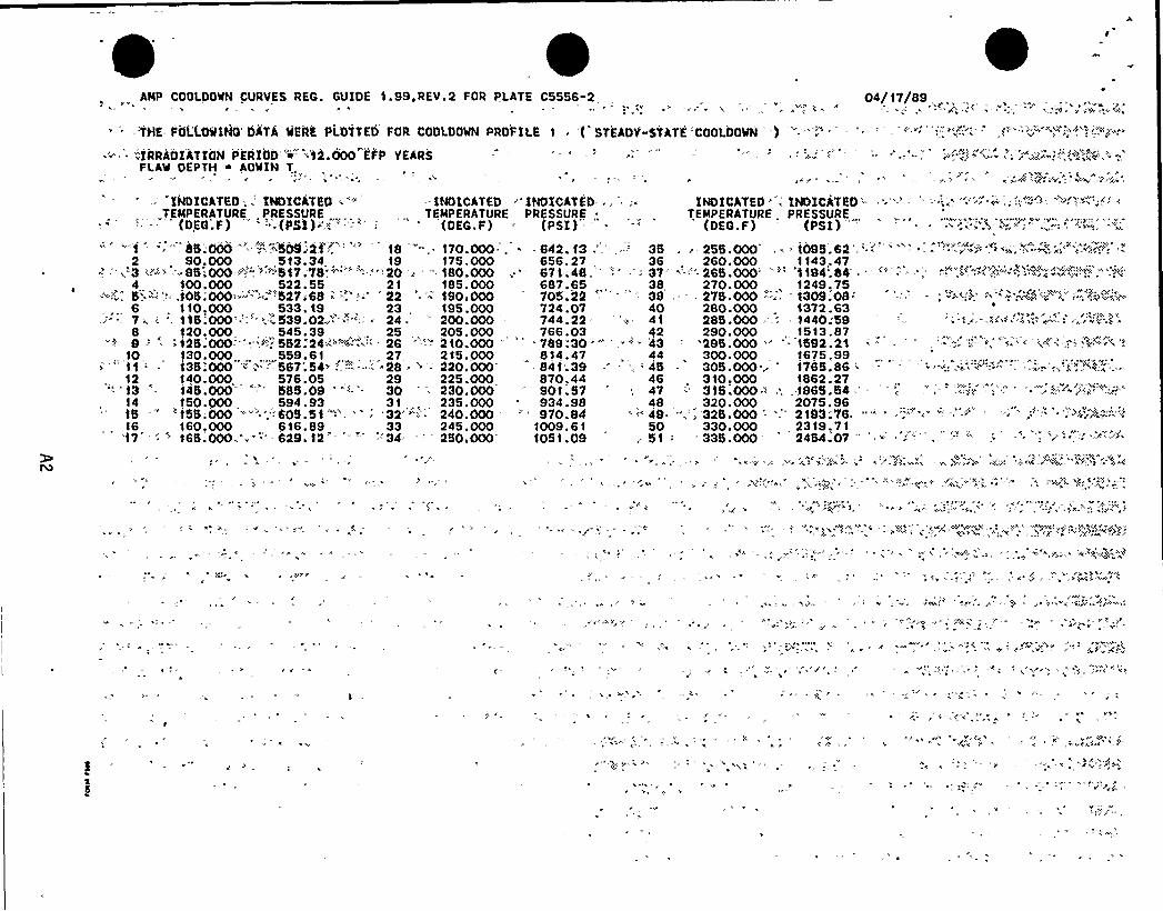
AMP COOLOOWN CURVES REG. GUIDE 1.99,REV.2 FOR PLATE C5556-2 04/17/89
-:THE: VOL'i.OPING DATA WERE PLOTTED FOR COOLOOWN PROFILE 1 . ( STEADY-STATE 'COOLOOWN 'r) -.-; .1RRAOIAT1OH PERIOD'=-'10.'000 EFP YEARS
FLAW DEPTH ~ AO'WIN T.r
IHDICATEO;..'HDICATEO» " - INDICATED ' INOXCATED,, IHDICATEO ''HDICATEO„TEMPERATURE PRESSURE „ ,TEMPERATURE PRESSURE TEMPERATURE „ PRESSURE,
(DEG.F) -~ (PS1)'.< ':"'' ' (OEG.F) - (PSI) '. ' (OEG.F) (PSI)
85'.000 '""";«":5(N;21".:-' 18 .— 170.000- . « - 642. 13 ='.-,.--'5 . - 255.000' ~ 1095.62''.
2 90.000 „,,513.34, . „19 175.000 656.27 36 260.000 1143.47'3 "-«'» -.85'.OOO-, ".".,", "'517;7$ '""-':-""20 ~ '". 180.000 „.'' 671.48,''''' '- -- 37'--'" 265.000'~'1194.84 ~
4 100. 000 522. 55 2 1 185. 000 687. 65, 38, 270.000, 1249. 755'.='rr'.".r,105;000'.»"- .'<. "527'6$ '" '-' 22 '- 190)000 705.22 .
' *- '39,— - 275.000 -"-:- 1309.08='-' ".'-'+» >''»'~~4'Z"~"'»~86
6 . 110,000 533. 19 „23 195.000 724.07 40 280.000 1372.637 . 115;000:";" '39.02," "":=' 24. '00.000 -
" 744.22= '- 41 285.000-; 1440:598 120. 000,, 545. 39,. 25, 205. 000, 766. 03 Q2 290. 000, 1513. 879 -: '125."000r':"',~"..'52:24'~'-:4"'". ~ 26 '"'-" 210.000 " ' 789.30 ""'-P - 43 -'.295;000 " ' 159'2.21 ~ ', ' ' ." . '-;;— ';, ''
(-'.,"'r-"-'»'"'"',10,
130.000., „, „„559.61 „„, 27, 215.000 „814.47,, 44 „300.000 1675.99.:'" 11 ' i35!000 """--567;54»:-'"'---'- -28 =-' 220.000 - 841'.39 - ...- '5 - 305.000.~ 176$ .86 ' -" « ~.--4'".'."-"12 140.000 576.05, 29 225.000 870.44 46 „310,000 1862.27
"". '13 '- 145.000 " 585.0$ '-'0 = 230.000 " 901.57, 47 .'15.000 " .; „-196$ .54 ' ";,".' "=;, ' '.:: &~""14 150.000, 594.93 31 „, 235.000 '34.98 48, 320.000 2075.9615
" 'i55;000 ":"":60$.51':"'. ': 32"--''-r 240.000 "'70.84 r:.r-4$ ",-.'25.000 - ".. 2193;76. --16 160,000 616.89 33 245.000 1009.61, 50 330.000 2319.71'17r '. - 165.000 .-". 629.12' ':-'34 ' 250.000 1051.09; 51:' 335.000 " 2454.07 "
'.Ar
r ~ 'r'.Vr.r. r r, 'prrrrr r *A '-:,'ri,r';,+h.."«r;,')
'Y '«
«

l'
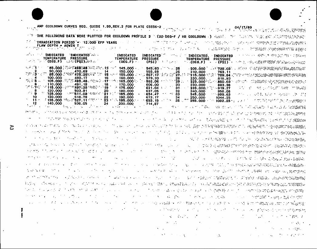
AMP COOLDOWN CURVES REG.„ GUIDE 1.99,REV 2 FOR PLATE C5556-2 ,.. .. . ., „. 04/17/89
:THE FOLiOWiNi >DATi WERE PLOTTED FOR COOLOOWN OROFILE 2 --.-{20>DEG-F / ttR 'COOLOOWN ) .-:.::;,:,='=.
IRRADIATION PERi00 "w','tl:000 EFP YEARSFLAW DEPTH .~ AOWIN T
INDICATEO '-INDICATEO - '-- INOICATED INDICATED': INDICATEO. " INDICATEOTEMPERATURE PRE$ SURE , TEMPERATURE PRESSURE TEMPERATURE PRESSURE
.- ''(DEG.f) .,i"'(PttI)~~~4.: .»-.'OEG.F) (PSI) ' ", "."' .(DEG.f) ' (PSI) < "-"" ''',, "..?".";-"":"';".'~~~a>'?''.'0',":»~:"".'-
85;000;."': ">>458~48 <:Z.', 13 '45.000 =,, 545;60 ~'-
~ 25 205.000 -- '739.03,2 „h 90.000,470.69,„„,, t4 150.000 555.98,,26, 210,000, „,763. 11..''"":=3" ' 95";000 '",,"'".7-'75'.-25~' ';,"" 15 -'="-'55 000 -''- „. 567-:-17 .i "'.;.!'. 27- '"2 t5;000 "'.'*'. 799:.94?.'>' ' ", ."'=~V„.«':.."""<,'w~»%>s:"4-;+'.>I'PA4 100. 000 480. 17 16 160. 000 579. 20 28 220. 000 818. 93
", „,', " 105.000 -;,. 8;485.48 --";-,"v. '17'""."'-', 165,000',"'h,' 592.06 '," ' '2$ ;, '" 225.000";.„, '„- 850.03 '
~ -,":," " ">h':»'~"~':. p„".,'-..(-"',4'„''»"'.":
',6,. 110.000 491. 19 „,, 18 „170.000 606.00 30 230.000 883.38-.7:: '''1'15.000 -" ".'4$7 29 '->'-".'.i'=; ' '19 ''75.000' '21.04 ' 31- -" 235.000.'' ..'919.27
8,
120,000 503.91 20 „ 180.000 637.05 32 240.000 958.089
'' -'f25.000 >-"'-"'5tt>08'":""'::.'21 "';'t85.000 '664.47 " "" 33 245;000' 999.6310 130.000 h, „518.79, 22 190.000 673. 17 34 „250.000 1044.25'35.000 '~; .>'27.'t "~ .' 23 " ''. '.195>000, . '693: 19
" '* 35 . " 255:000 "'= 1092.25 '12 140,000, 536.05 „ ,
24 200.000 , 714,87

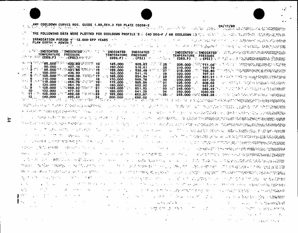
.AMP COOLDOWN CURVES REG. GUIDE,1-99,REV.2 FOR PLATE C5556-2 „ 04/17/89
THE FOLLOlONQ DATA QEAK PLOTTED FOR CODLOOWN PROFILE "3; (40 DKG"F / HR COOLOOWN -:,.}.".'RRADIATIONPERIOD ~"" {2.000-:EFP YEARS
FLAW DEPTH ~ AOWIN T
::. INDICATEO:", -'INDIClTEO'; " '"" INDICATE'D INDICATED '., ", 'NDICATED'..;.:-'NDICATEO'EMPERATUREPRESSURE
,TEMPERATURE PRESSURE TEMPERATURE PRESSURE'""'«"'(DEG>F) ."-'(PSI)«1 > ~'« " (OEG.F) ~ (PSI) '- "- — '- 1«z -(DEG.F);- - <. (PSI): <."
-"""85.000 . '422;80'»"" I."'3 - - 145;000 - 505.83 .. - 25 '205;000:., ~ --~'711.06 ~' '< ."'." ("<Y:<~k@c~'<,."."-'..- '.'»<.-'~«'~
2 90.000 „„, 427< 14,„,„,, 14 150.000 516.61, 26 210.000, 737.79'' '3 ."" -'5.000 "'<,:.~<434'-".85" ""'' '''15 '' "'55.000 '28.48 ".":"" .,'"27 "' 215.000, '"-" "768.804,< „100.000 „436.93 16 160.000 541. 15 28 220.000,797.815 "'=' 105.000 '--'»"-442:38'<<V»~-:.'-'7 .. -"-. 185<000 554 94 ' '=-29 '25 000 -- 831121: - '.-:-" " '".'-'' ""-'"'"" -~."."'=.,'","~»<- »-=c.6 , 110.000 448.32 ,18 170.000 569.78 30 , 230.000 867.307 -'. 115.000 - '-.<454 <78'''- --"" .'19'75.000 -.' 585.88 - ' 31 235.000:,"'08.028 120. 000 461. 70, „20,, 180. 000 .„602. 92 32, 240. 000, 947,64,9 " 125.000 '. "'.'489.22'."," ': '1' "185.000 -.
-~ 621.52 . ~
" 33 "'- 245.000'-': 882.4310 130. 000 „, 477. 32 22 190.000 64 1 . 39 34 250. 000, 1040. 5811 - ':"-"". 135.000 ~"' 486.08 -'"w ".'"."23 '95.000 - -",862 97- ~ - «35 ..- 255.000:.<~'~ 1092.38 ~ '- '.':»'« '<'«-'<~''":<.*-. ''~'~~k<k12, 140.,000, ,
495,43 , .24„,„ 200«000 „,,... 686.02
<>h« --.'

ll
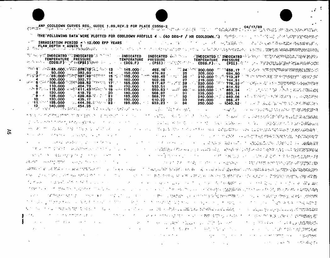
AMP COOLOOWN CURVES REG,„GUIDE 1.99,REV.2 FOR PLATE C5556-2, , 04/17/89
"THE-'FOLLOWING DATA'ERE PLOTTED FOR COOLOOWN PROFILE 4 :. (60 DEG"F / HR COOLOOWN."-.)
IRRADIATION'PERIOD < '2!000 EFP YEARS -,. '.- "-. - - ', .-: .„'"~;-:,.':-,",,"„',",, ~{'-;;.;~..~,"„,.;,:1~;-w;-sl:„-.FLAW DEPTH %, AOWIN T
"'--':=',"'-,1NDICATEO'-='::INDiiATEO':-" -: iNOICATED -INDI'CATED. i"-'- '= -.
- "'INDICATEO'.-"ImICATEO -': '='-:- -'".".- ="~~~"="="P..";: '-~~{"N'EMPERATUREPRESSURE TEMPERATURE PRESSURE
,TEMPERATURE PRESSURE
i(DEC F')':-.".1{((PSI).''~" =: — . -~ (OEG.F), (PSI) "'.':- ''=: (DEQ;F) ~ ~ 'PSI)-i"-" .'
'r~2'~.:~~i~X~'-''"-~'88'.000
'>i'348'';""t0;c "'«,—13 '48.000 «. 465.16;, 24- '"'. 200;000'" '688.,17 -.."-'.-'-; ";.'..". ~;"";""Y"''~N"~"'"'+." '~
. 2,, 90.000,„„382.60,... 14, „, 150.000, 476.82 25 205.000 684,903 '"98:000"*,""-r. 387'<49 " ~ '8 r - 185.000 '89.48 "
~ 26 2'l0;000 .;: ''l3.874, ,100.000, „„392.77... 16 , 160.000
,502.96 27 215.000 „, 744.91{~"'8" "-'$08;000' ~~""'398.52 "~""" ': '17. ' 165.000 '17.67 ' .';. 28 ' 220.'000 " -'7$ .32"
6 110.000 404.73 „18 170.000 533.51 29 225.000 814.52"'7: -" " 118.000 '""'l~- ''411.43-"'", -'-', -"- 19 -"- - 175{000 ~ .85083 ' =-- 30-:. 230000» .'83.-34: ''' " '--, ~ - .'' . ~';" .=-{'$~''6<8 120.000 418.72, 20 180.000 568.97 31 235.000 895. 11-' - " 125.000 "' '- 426;63. '
= 2l 185.000 ~ 588.77 '" ' 32 240.000."" .: 940.0610 130.000 435. 17, 1 22 190.000 610. 22 33 245.000 988. 47'11" '* ' 135;000 '-'44.36.''=' " 23 195.000 '- 633.23 ' "'4 250.000 " 1040.52' .- -'';,'.;";. ':; '. "-' .'' ';~'.""'~''; )'.;.?"'.12 140,000 454.35
* r
;1
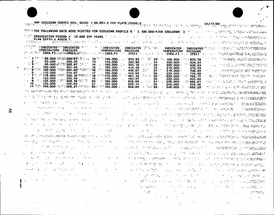
, AMP COOLOOWN CURVES REG.„ GUIDE 1,99,REV.2 FOR PLATE,C5556-2 . . . „, , 04/17/89C
". 'THK FaiLOitING DATA,WERE PLDTTED FOR COOLOOWN PROFILE 5" (;000 DEG-F/HR CaOLOOWN. ) -': '. --- .. "-.'..-"=- . '":~-:, e":~~-; '-.
"',." . IRRADIATION*'PERIOD <'2;000 EFP YEARS '; '; '; — -, - ..' ". - - " ' ""'' " . ", ", . ~ '""x"'.'.",",,FLAW DEPTH,M AOWIN T
C
:i'INDICATEO'"-"INDICATEO""'' '" INDICATED INDICATED,"'-",,'" INDICATEO, 'NDICATEO',,-'', -" ''» '" -,':'";''""!N'"'.'~„"'.-'EMPERATURE
PRESSURE„
TEMPERATURE PRESSURE TEMPERATURE PRESSURE(BEG.F) w~~si-'"(PSI}~&'"~'=: ~ "~ (OEG.F) ' (PSI) '', .- -"~' .="'- (DEG.F):- - (PSI).':. 85:000-"Z~.',::285-N" -"." - ~ 12 '40;000 . 370.S3 " ',i "23 '. 185.000 = "- - 578.78,, 2 90.000 , .290.35. 13 145,000 . 382.83 , , 24 200.000 „ 605.643' . -8B!000;K~"-'-.'295.67'.." 14, -150.000,. 396. 12 ~ " 25 205.000 —, '638.834, 100. 000 301. 46, „15,, 155. 000 4 10. 49,, 26, 210. 000 670. 59. ', "'5'"''"»'05':000 "'.,:;>'"307.80: ';..:!"..". 16 ..'60.000" '- 426.07 ', „; 27 '15.000. 706.886, 110.000 314.67,, 17, 165.000,, 442.89 28 220.000 745.98
7 '=' ='"115'000 ",~~'"-'''322'8'~-'~~"r-'8 '",'-'-170 000'
461 12 "': '' '9 '- '225.000"'788 178 120.000 ,330.30 „,,„ 19,, 175.000 480.87 „ 30 230.000 833.609 -'--,'125.000 .'--'39.48 ' .- 20 ":,-.180.000 S02.08 , „ . 3'1-'-. 235.000-. — ".. 882.61- :--'" ''- -;;;.-': -.-'"".'*
10 130.000 348.80 21 185.000 525. 14 „32 240.000 935.38".'$35:000:=»';=' 3B9.27, '-''".-': 22 "= "-190.000 '49-;89 , -.-='-33- 245.000 =- '-'892.23'
~
h
CC-
~ C

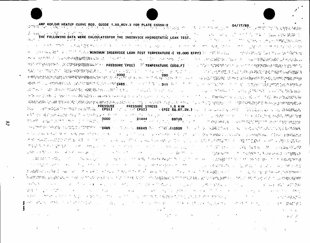
,.„ ...AMP 60F/HR HEATUP CURVE REG. GUIOE 1.99,REV.2 FOR PLATE C5556-2 04/ 17/89
THE FOLLOWING DATA WERE CALCULATEOFOR THE INSERVICE HYDROSTATIC LEAK TEST.
' '. "'MINIMUM INSERVICE LEAK TEST TEMPERATURE ( 12.000 EFPY) '-
h
'~ rh ''c''-'-""''- '- x": j~-"P~J<f'i-~~" "=" PRESSURE'(PSI) TEMPERATURE: (OEQ;F)2000, 290icing',,;rh hcV;,"cV-aha»: .'..—,~VF'c;,h.;W @Pc.> h;." c-- . 'h, = -, „c,
, '311
PRESSURE. (PSI)
2000h rr
PRESSURE STRESS, 1.5 K1M; -.'PSI) ' (PSI'G.RT.IN.
21444,, 89745
'*'":r "',"". ~ '. "., "-, '". '" '"2485': = '. - ..26645 '=" ", '"."': ..112505
C
f
C7
'C C

$ '/
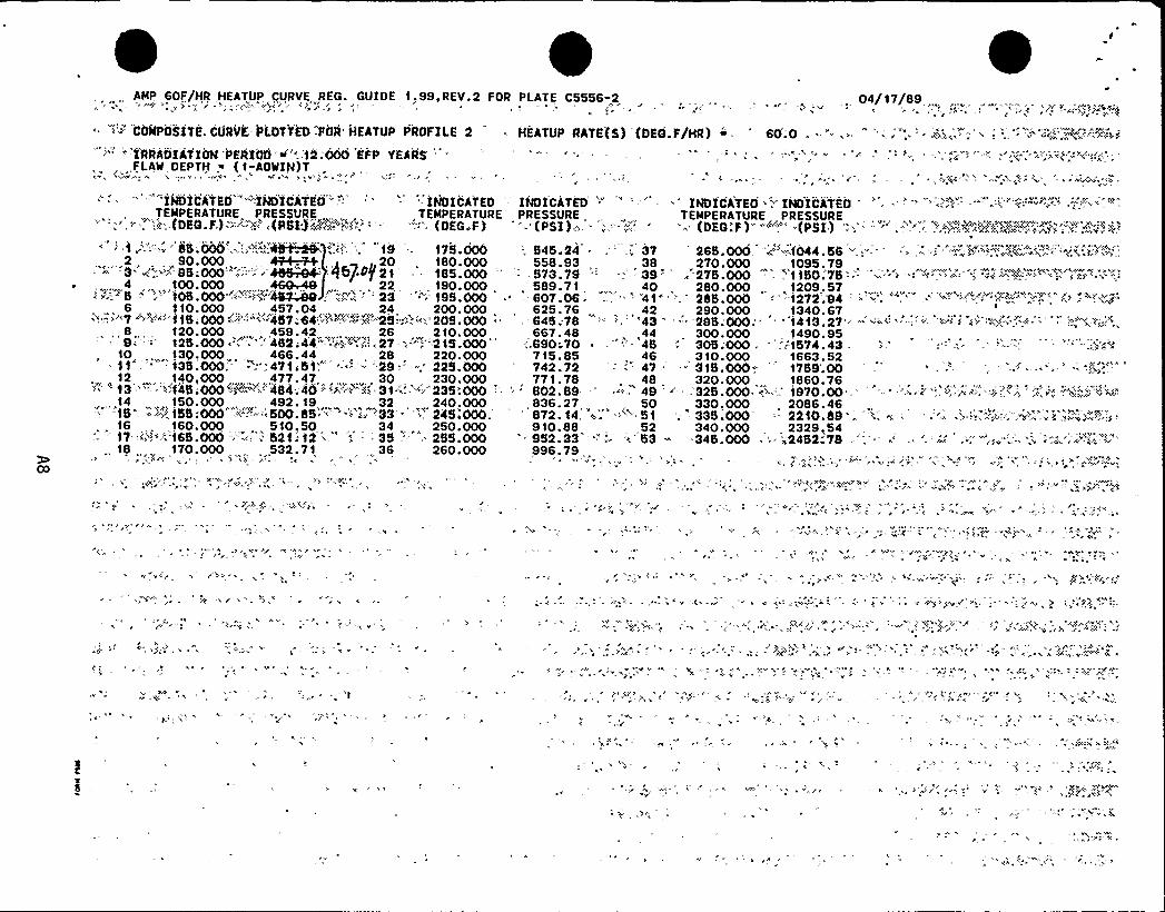
AMP, 60F/HR HEATUP, CURVE.„REG. GUIDE 1,99,REV.2 FOR PLATE C5556-2 04/17/89
COMPOSITE CURVE-PLOTTED .FOR'EATUP PROFILE 2
'" 'RRAOKATION PERIOD(,('.,'12;000 EFP YEARS'',FLAWDEPTH .% (1-AOWIN)T
HEATUP RATE(S) (DEQ.F/HR) " " 60.0 . " '-, " '''„('""..'. i«h,":.': ' "'« 'R.'"'='«':e
>INDiCATEO ""'.INDICATEO" "-'' -- '- INDICATED'"
INDICATED ""
TEMPERATURE PRESSURE,,
TEMPERATURE PRESSURE," . ':>: (DES.F)-"--'-'-'«(" (PSI)'.A:«~«»"'-'- "'OEG.F) " '- (PSI): .. ''."„:"- -,":;
-
INDICATEO 'NDICi'TEO - '- - '--.-'.--':.'' " ---,,":"'-'"-."''.- -';:-".='""'"--TEMPERATURE PRESSURE
(DEQ F ) (»«> (PSI ) P j «('>»P +& 1''(+'~ z h (
"1 "='-'-:-." '5.000'.-...'.>"",".l;4~8"2 „, „90.000 „49+~
= - -3. ( '.."SS;OOO':..-:—:.¹SS-.@C'„.
4 „, 100.000 „,469«48'PS -'-'- 105.000-'»'"-'". ¹IPAO
19 175.000 '-, 545.24 . „37 26$ .000 " ~1044.5$ '" ":> -.".h- '"-"''";-~:.o~«.'; -«'q",»'''y'«'"vl™««»20 . 180.000 558.93
,38
,270.000 ,1095.79
457~$ 21 185.000 ' 573.79 " — '-. 39' 2VS.OOO .'150:VS - - ''-' " " '"-"- ' '-'': .
22 190.000 589.71 40 280.000 1209,57'3 '"~ 195.000 '-807.06 ~,.'" ".'41» '85.000 -'1272 94 '''=" '"
',110. 000,, 457. 04,„„„24 200. 000 .-'.=.'" 7 «=:.-'-' 1$ .000-:.'':<'¹57;64:.'>"-:-:-"4'-«2S-;".-:: 205.000',e.„, . 120.000,„, 459.42 „, „. 26, 210.000S:'-"'5.000 " '"''482;44 -":..-<.».-'7-
.-'i"'-215.000'0,
130.000 466.44 28 220.000. 135.000; -:"4'l1>51'."( '-.: '-29.. -'25.000
12 „140,000 „,477.47, „,, 30 „230.000>'"'13 "'- '-:1¹5;000"'F'--",.'484;¹0-''»»'~P "".31"'."> 235'.000 '-
...14 „„,150.000„„, 492. 19 „„32 240.000-.-'-1$ ". «'-.':-".~155:000«.~:"'::-,('00.85.«« .'- ». ~33'>'45'000.'6,160.000, 510,50 34 .,„250.00017. >»~.'s".:-j65'000 -:,===..."-; -521 '. 12 «--'(" .; 35 -'*,. 255,000
., 18 „, „170.000 532. 71 36 260.000
625.76,.645;78
667.48:.690;70
715.85742.72771. 78802.89
,836.27872. 14910. 88
" 952.33996.79
, 42(4344-"-454647484950'(»"':-"'152
>. 53
290.000 1340.67-.'29$ .000»" ''1413.27'= " ''(-«:'. ":< '»»'>""-:,':»«,".» ''
300. 000 1490. 95305.'000 . ':-15'l4. 43
„310.000 1663.52." 31$ .000 . 1759'.00320.000
, 1860.76. 325.000. ~~ ','970.00 " "- "",:hei',. >h, >(~>, 4':, 'Y', 'v'„.:"",'<:...„i>««'4"
330.000 2086.46'; - 335.000 -.- 2210.89; '. -
~ = =:= '.'"."-::-:;;-"-."-':"-=."-.7 .. ''«>'-'.:K;» -.
340.000 , . 2329.54345.000 . '-.. '«24521 VB
«'(
y ''p
'(V
Y,(
h«
(V
» Y

'L1
"f
I'
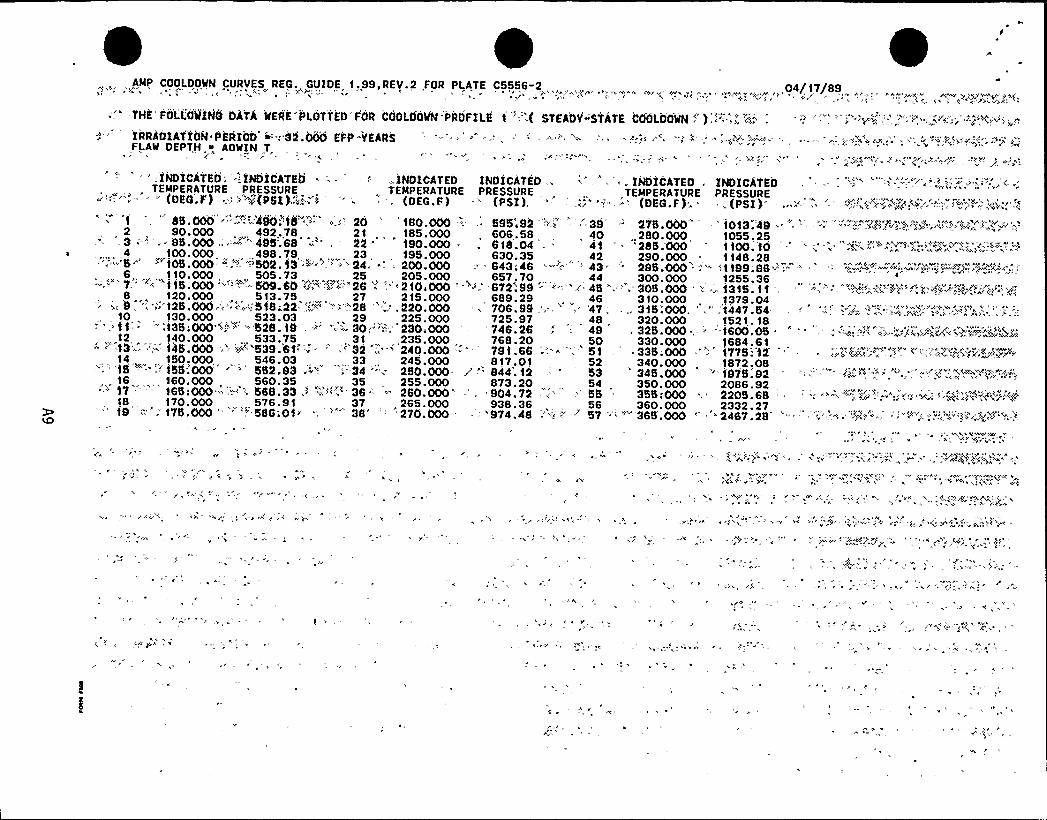
AMP COOLOOWN CURVES REG. GUIDE 1,99,REV.2,FOR PLATE C5556-2, . „ „,, „ . , 04/17/89
""'-THE'FOLL'OQINO DATA MERE'PLOTTED'FOR COOLOOWN PROFILF. t '.( STEADY"'STATE COOLOOWN ','-;.;, ~": , '". ' 'w:,-', " *",.„.'".'' ":";<"~"~
IRRADIATION PERIOb ~> .'32.000'FP»YEARSFLAW DEPTH AOWIN T,
INDICATEO,' INDICATEO = - '',> INO1CATED INDICATED-,: "'. INDICATEO . INDICATEOTEMPERATURE PRESSURE , „ TEMPERATURE PRESSURE „ , TEMPERATURE PRESSURE~'";'.>--«: - (DEG.F) -::::.>(PSI)."„ 1 ',. '-, (OEG.F) - (PSI). ' .;; -' (DEG.F). ~ ',(PSI)'f
,'"'85.000 " .: ";."480.'"l8'."':',,i'., 20 '180.000 '-.- ..'95'.92 ".'"'.,'. '8', 275.000' '013".'48 '" '. "„
2 90.000 , 492,78 21, , 185.000„ 606.58
„ 40 „280.000 1055.25-'3 '-" , ~ 85.000 ,.:-'= 485;68 -" . 22 " 190.000 — . 618.04:. 41 - '285.000 tt00.'f04 100.000 498.79,
, „ 23, , '195.000 630.35 , ,42 290.000 —
,1148,28'-";-" -5-'.'0$ .000'- =,- ''502. i3 =t''-"'- ""-'= 24. - : 200.OOO -- 643:46 - ; =
- 43 '95.000',; .tf89.9$ -:,='« '--.=,-".-'-'. -.":""'-'-"--"—"-'.'":V'"'-" -'
110.000 505.73 25 205.000 657.70 44 300.000 1255.36""'""''"7-" -:- ti5.000 '"'. ='-= 509.60 N'"'. ""26 " " '10 000 '>.-'72'.99 " "-'"*45 ".'''0$ .000 '" - 1315. tt8,, 120,. 000, 513. 75,,„, 27 „215. 000, 689. 29 „46, 310. 000 ...1379. 04i; 8 '. ", >>'t25.'000':-;":::.~'-.'518«22 -,Yi'" '-"-:".28'.:,220.000 ~ 706.99 '>>" '47,', 315:000. ',','t447.'54. ''"', =.;.:;", ''-":.>
»,'Kc':,"'"".>'>.':.'"-.'A~",.','~.'0130.000 ,. 523.03 ,, 29 225.000 725.97 , , 48, 320.000 1521.18-;f35;000.";":- "- 528.18 ,-~':-,'--- 30:-":„ 230.000 746.26 ".---'8 , 325.000 ., ~ -=1600.05 ' .':-~:;~'~~ ",:i::,;,:.-:««'~":"-«.;"."'";:~"5N,12 140.000 ... 533.75 . 31 . ,235.000, 768.20 , 50 330.000 ,, 1684.61" '" t3-» -';.~ 14$ .000:.-'> »'"'539.6t"''= -' -''- 32 ; "- 240.000 " '91.66 :-'- '=: 51 = - . 335;000 ''-'- 1775 'l2' ''-~~"'«>'14 1S0.000, 546.03, 33 ., 245.000, 817.01 52 340.000, 1872.08;'''tS '>-''--'55'.000''52.93 .'34'>-': 2SO.OOO- .''" 844'.12 .. '3 345.000 . " 1975.92 ' ' -'..'-:."» ='"'.-'..'". < .'.-'-~.'."8.'.''.,
.„ 16 ,, 160.000 560.35 „ 35 255.000 873.20 54 . 350.000 2086.92''-~ 17 - - - 165:000 -:.".''~ 568.33 .> "i(:i""-36-" -'80.000'-.' 904.72 ."'. '' 55 . 355:000 . 2205.68 ':..'-.-".7Y«.'."=":;««w> '"""';;"",'."«<,"'a~)'418 170. 000, 576. 91 37, . 265. 000, 938. 36, 56 360. 000 2332. 27t8 -" : 175.000 " "''- 586 Of> ": "" 38" '' '270.000 - .'''974.48 "'::. > 57 ." "''365'.000 ''467.'28 '-" '''"".~" "::<':""~
'"'':-'"'."-<"-'-"1'""'"""""~ ..';

%1
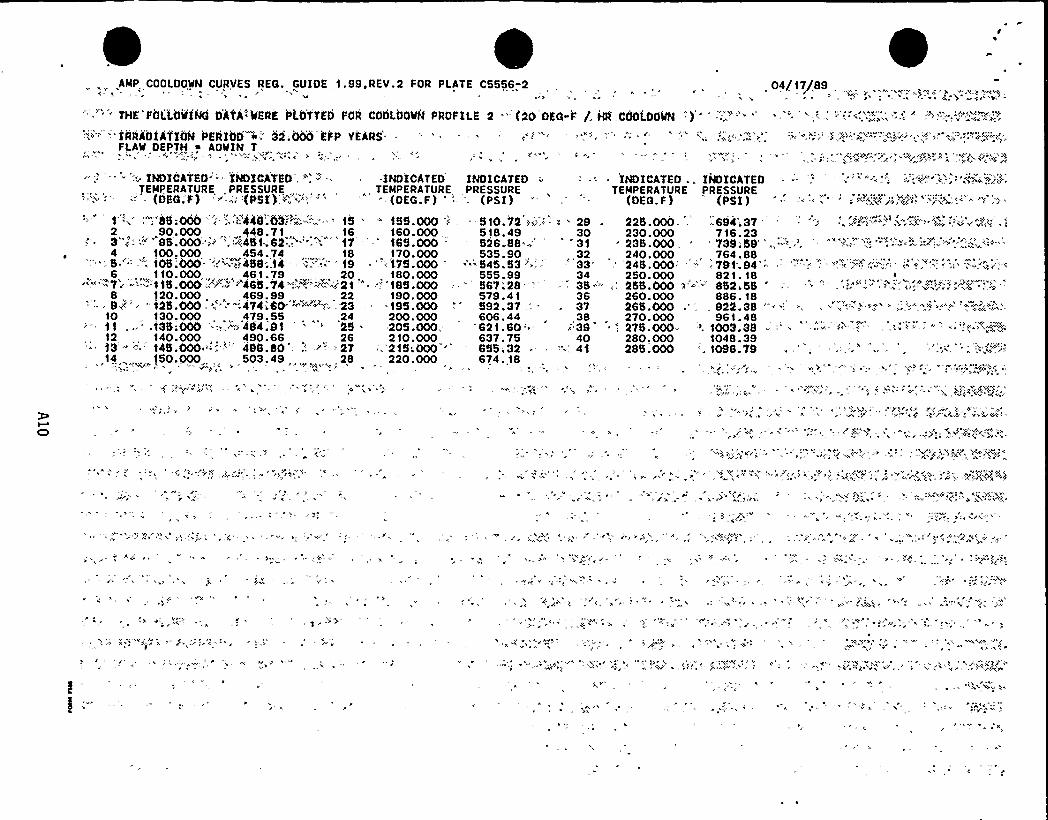
.AMP, COOLDOWN CURVES REG. GUIDE 1.99,REV.2 FOR PLATE C5556.-2, , 04/17/89
'tA
'."" THE'I aLiOiiiNG D'ATA'VERE >LO'TTED t OR COOLOOWN PROFIt.E 2 -'2O'DEG-r /. HR,COOiDOWN ):"7" '-'RRAOfATION PERIOD 4" 32.000 EFP VE4RS"
FLAW DEPTH ~ AOWIN T y»»
;; INDICATEO '"-" INDICATED .": ~ -- .INDICATED INDICATED
TEMPERATURE ,PRESSURE,
TEMPERATURE PRESSURE-'= - (DEG;F)" ~'.':»(PSI):>";"'",'" " ' (OEG.F) ''- (PSI)
:"8$ ;000" '»','»448".03 l'».'",'"'8 '- 188.000 "i -8t0.V2 >~".': .2, „90.000,448.71 „„16 160.000 518.493""-''~ 8$ .000 "» ': '451-62... '--'. '7 ''- 168.000 826.88 ='' '
, 100,000 454.74 . 18 170.000 535.90,,"'':-S.'.»-"'05.'000 'Y1458:t4 - .''" 19 '1V8.000 - " 'S45.836 ,, 110.000,„ „,, 46,1.79 ,,„.„,„,, 20, t80.000 555.99", ."7'i=-'-- -'::115.000; ~ .-" ~"465;"t4'-';.~ -~,"=:~21 "*- »~ '188;000 - 86V:288 „120.000, . 469.99 „22 190.000 579.41
"" . = 8-"" ~ "125.000 "': -474'.60'"-"='~ -'- -23 . - =188.000 -'- 892.37 .'-
10 130.000, 479. 55 „, .24 200.000 606. 44.t35:000- '.; - ""~484.9t ' '8
.208.000„*62t.60'.»'2,
'140.000, „490.66 ., 26 210.000 637.7513 '- '45.000 '-'."-"" 488.80:: -~- '27 -. 218:000 '' 685;3214 , 150.000,, 503.49 „,„,„ ,28 220.000 674. 18
INDICATED .. INDICATEDTEMPERATURE ,PRESSURE
(DEG.F)'
(PSI) —;'-; '"..' .: ~:"~„'~%'g'V»s! ".-'-",<„'.:-'"'8
30'31 *
, 32'' '333435-''-363738
» 3940
'..." 4t'V
»
225.000- - =684;37 ' - '." .-:""'F'~"'-'",".-;<" 5=. ',"'v~"PA .»230.000 716.23238.000, 739-;59240.000
„ „ 764.8824$ . 000 - 791.. 94-250. 000,, 821. 18255.000 "-'"" 852.55260.000 886. 18265.000 .'" 922.38 "270.000 961. 4827$ .000= '. 1003.38280.000 1048.39285.000'. 1098.79
''2
»»
»
S»"
- »
1-
*
'»),

4 J
'
r
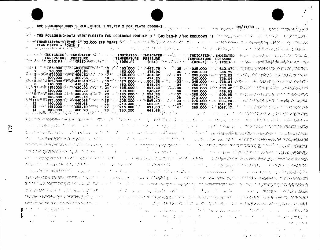
AMP,. COOLOOWN CURVES REG, GUIDE 1.99,REV.2 FOR PLATE C5556;2 04/17/89
THE FOLLOltINQ'DATA-WERE'LOTTED FOR CdOLOOWN PROFILE '3 -» (40 DEG"F, /'R COOLOOWN
""IRRADIATIOM''PERIOO''"'32:000 EFP "YEARS -'.'-FLA'W DEPTH ~ AOWIN T
- - INDICATEO' 'INDICATEO'-.- . INDICATED -INOICATED-'EMPERATUREPRESSURE TEMPERATURE PRESSURE'- '- ' (DEC'.F)- '-: 'L(PSX)'P>i'" -'-'"." '";. (OEG.F) (PSI)
1 -"-.''-85:000 - "-"-400!'05~@ 'g, 15 ." . 155.000'-,,: 467;79 -, 292 , 90.000 „ ,,403,64 16 160.000
, „ 475.96 30'- "-.: 3 - -".--.-95;000»='M'-::406.'52:;,'.'~ 17: , 165.000 ; "-: 484.82 '" '; 31~ ,, 4 , 100.000 409.68 18,„ 170.000 494.25 „ 32'«'""'. 5--';,'".'.-105 000-'":."-"-',""'413;.'l3''"': '" 19 " '175.000'- =" ".504.58 ~ '=:;.-'," 336,, 110,000 „, 416.86 „20, 180.000, 515.64 34--.'" 7": -"-'."1 15.'-000 -",.::-"."--'420;92 .."'."." '-:.'21* l -185;000.: '27.63 - - =."." 35
8, 120,000,
425.29 „ „22
,190.000 540.42, 36
""'~""'-9-';:'"».".125;000 "-.":i'30.05 '"'i""'3 ,. "195;000 '. ".'54.35 . " '7.10 130.000 „ .435. 18,„ „ ,, 24 200.000 569.34 38~''""ff-'~"".,""-'f35000 '».;." ".'"4'40t68 '''''-"25''''; " 205.000 ',".585.40'''.-'39
12 „ „ 140,000 „„,,„446.68 „, , 26, 210.000 602.81... ,40f3 '." 145-.000,. '-'.'453 1$ ~ '" 27 .'215;000 . = 621.60 .
'- '4114, „,, 150.,000 .,460.20 „, 28 220.000 641.66, .
'NDICATEO. INDICATEOTEMPERATURE PRESSURE
(DEG.F) '-(PSI). —- "."<-~ - ='=~-."'-." ."-'..»:" "'~'>.-'
225-.000 -,.'63.4'f'~=-.-'-';Y:j'-, ;~'7<'AY~". ',< ~~j"'V-", 230.000 686.75
235,000 w'" =712 03 - .=~,. '' ''-' „' '" *"
~'40,000739.04 „.'"'-', 245.000'" "" '788 31 " ')250.,000 799.66 „255.000 "''33.40 " '' '- "'. ~;."" ." ' '.»,~""'~.",Vi";.i~-.i'":.260.000 , 869.82
270.000 950.97
280.000 ... 1044.85285.000 1097. 17
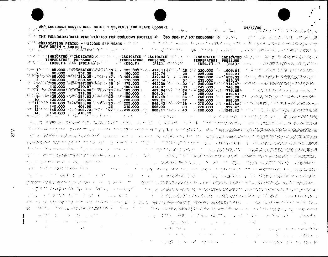
AMP COOLDOWN CURVES REG. GUIDE 1.99,REV.2 FOR PLATE C5556-2 04/17/89
'"''TKE FOL'LOWINO 'OATS WERE PLOTTED FOR COOLQOWN PROFILE 4 (60 DEG F',/-'RRA01ATION PERIOD > "32.000 EFP YEARS "
FLAW DEPTH % AOWIN T
KR'COOLOOWN
'')'INDICATEO"
'~ INDICATED .»' " ''„'NDICATEDTEMPERATURE PRESSURE TEMPERATURE
(DEG.F), ~: "'~ '(PSI):~.:i ~.-- = 'DEG.F)85.000';";:.".- "g'354>69»»"a;~~'.-'i '5 -' 155.000'"
2, 90.000 ,, 357.38 16 160.0003 "-,: -'-"; BS;000" '~+ '380;35- .; "-':.-: ~ --17. ': 165.000
~ . 4, „100.000,, 363.52, 18 „170.000'' 5'. '.'" 10$ :000",<~N'387";05".«"'y..",'„.'- .19 ':" " 175.0006 1 10. 000 370. 87 20 180. 000"''-7 -»~~-.» 115:000»',~ »:-375'06~»~'P.- «'2t = -'=. '185.000 '-.
8 120. 000 379. 58, 22 190„. 000" '- 9-="" 125.000-"--~~''84.52".I"'-"»'-"'"""23'"— ""'"195a000,10 130.000 389.86 24 200.000
»-'-'-'-11 " '35:000 " -:-'='<395.:68 -'=--.'~ 25 " -:-,.'205.-000 -—
12, t40.000 „, 401.96,, 26 210.00013 "»'> 145;000' -'.::"408.73-': - 27-'. 215,000 .
'4150.000 416. 10
424.t 1
432.74,442.04452. 14463!'08474.87487.64501. 31516'; 19532.21549.43568.09588.11
- 2829
-'- 3031
»'32, 33-'4
353837
.""»'- '"'«'"383940
- INDICATED '.""PRESSURE
(PSI) =
. 'NDICATEO '..INDICATEOTEMPERATURE PRESSURE
(DEG.F) 'PS?),'' '20.000 '.609.'Bt
225.000 . 633.21230.000 . "-'„659.32
'35.000. 685.37240.000. =-''Vt4".67 "'-'= -.''~ "-"'.'-"="".a!'..''.-',". ~-. ~".
245.000, 746.08— "-" 250.000 *»--y
779.88'-'55.000816.51260.000 '" BSS;.75265.000 , 898.05
- 270.000 ~'."'43 52
275.000, „,992.47*-280.000 '104S»12 '"'
», »y).9
'; i»S.« yy
-"y . yr
«
, C
y
,, C
»« C.
,.*-y
«
y ~ y

,T
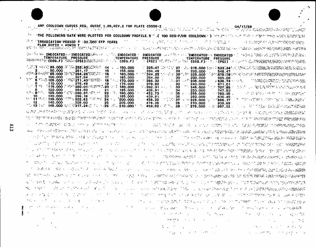
AMP COOLOOWN CURVES REG. GUIDE 1.99,REV.2 FOR PLATE C5556-2 . . . , , „ 04/17/89
-7'NE-taLLOWiNG'DAT'a'ERE::i LritiEO FOR COOLOOWN PROFILE-.S'.,( 100 OEG-F/NR COOLOOWN: ) '=:"'..:,.--: -'=., ":- " - --'~-.'.'-'.-'-:.-=-.".," - -'::=e<. „.'-='.
'IRRAOiiTI'ON:PERiOO. " -:32-.'OOO'EFP YEARSFLAW,DEPTH, ~ AOWIN T,
INDItATEO:.» -IHDICATEO:;.'- --', ''.- INDICATED INDICATED,'.. - '", '' 'INDICATEO '-.-IHDICATEOTEMPERATURE PRESSURE TEMPERATURE PRESSURE TEMPERATURE PRESSURE-'-~'.""'"""'V(DEG.F),'~'."'»,'':, (PSI)~»,",&»'-" ''' ('OEG.F) '-(PSI) "'."""";"' ' "'-'. {DEG.F). ":- --{PSI) .' .-'-" '. -. =.-'»» i.".V':."-"-»-" "" *:"'.-".".i:;~-'i.-"~'P„'
"-»'-' 85.000''-.". 258.;40~6»i '-". 14 .. 1SO.OOO 325i47 -'„-..'7 '.:, 215;000 '.,': ~ '523".34"'- .,",5">-, ."-; .'"<»~-~'< «;"»F" » "2 „ . 90,000, „ 26t,17„„,,„ 15 155.000 ,334.49 , , 28 220.000 . 548.47
5 ~ 000 "" r V;.'28$ ''26%~»'.+ „7,':...'.''18 '' 180 000 '",344 25''.'.;4 29 '- H'-.22$ OOO,.''575 "l8'»» '< "-'.-.i'" Pg""+""~R:. +W""~4, , 100.000 . 267.64 , 17 165.000 354.88 , 30 230.000 605.085 ': 105.000 ''-«."271 40-"'K'.-~,'-" 18 ' 170;000 - " 386.32 ' '- 31 -.'.-"'23$ :000 "
.~ 638.74 '. -.-: -''-';:.'',.'~%=.;,.';;,';.o'- - ':-~ »"..96 „1 10.000 275. 49 19, 175. 000 378. 82 32 240. 000, 671. 01
,7 "-.. f tS,OOO „'"'-"'.:-. 280:Ot:,'-5 .»'..20 . '.-180.000 ..',.392.31 . „: ', 33, 2 $ .000 '.." 707;85.'. 120.000, „„, 284.90, . 21, 185.000, 406.91, 34 250.000 747.53-'..": 9'-'-'-- 12$ .000 '" i"'."''.':„290.31.".".'. " '2 ' 190.000 '22.73 ''. 3$ - 255.000 790;35 =10, . 130,000..., 296. 18 „, 23,195.000 439.81, 36 260.000 836.45tt '"'*'35.'000 ''''<:302.62 '"'"""- 24 ":: '200;000 . 458.32 " .=-.';. 37 "- -. 26$ .000 "
- '888.1712 , 140.000 ,, 309.60 25 205.000 ,478.38 38 , 270.000 939.6913 -' 145.000 ",';""'':""3t7.24:.":" .. ";28 ;"-.''...'"210.000 -"'.,499.92 . »'..: 39 ;- 275.000 ,"-'997.32-
0 F+
XA:
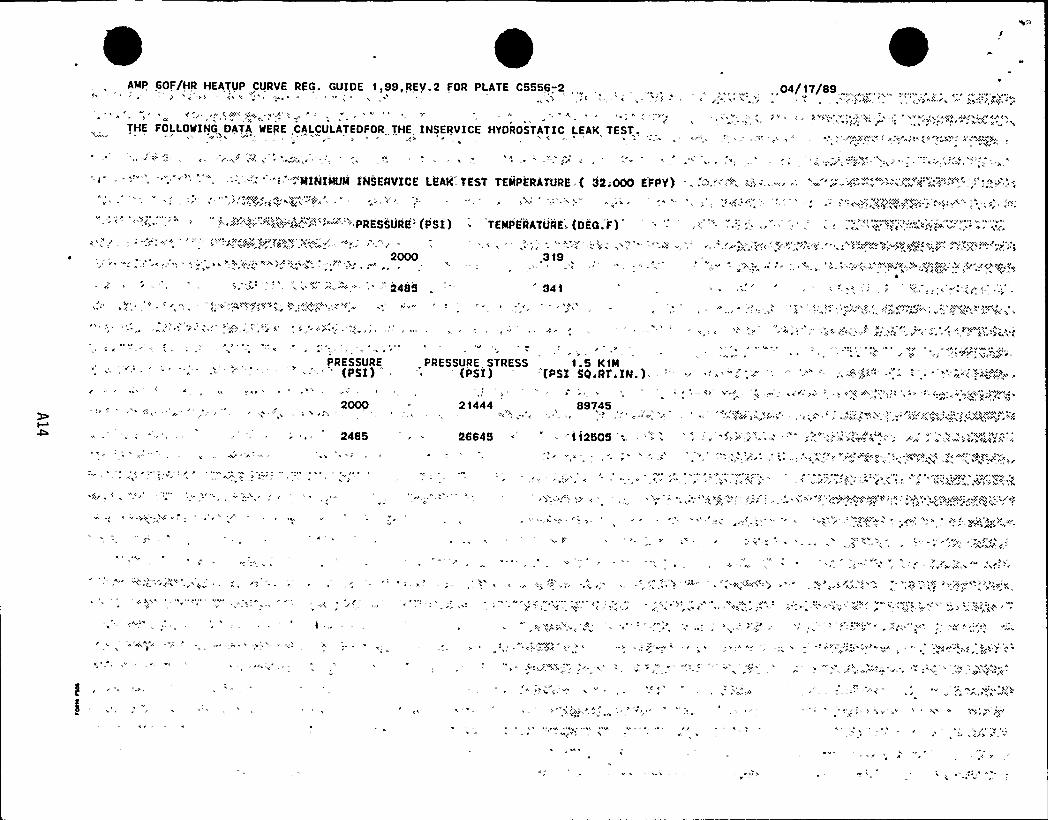
AMP, 60F/HR HEATUP CURVE REG. GUIDE 1,99,REV.2 FOR PLATE C5556.-2 „04/17/89
THE FOLLOWING DATA WERE CALCULATEDFOR THE INSERVICE HYDROSTATIC LEAK TEST,t
"i '""MINIMUMINSERVICE LEAK-TEST TEMPE'RAZURE. ( 32;000 EFPY) .! '-""'. -=;.'-"--" '="~.='.~'--" "'.~.''~'' ''-"'."-',"!2" '"1
" '> """'-",o-'gg';"ga..'"2"'~'-":PRESSURE" (PSI) TEMPERATURE.. (OEG. F)
2000 ,3 19
fi '*"'~'."- -' ",.'-'=-'- ''2485
A
?
PRESSURE-"'- 'PSI)
*
,PRESSURE, STRESS , 1.5 K1M'PSI) " "(PSI SOiRT.IN.)- -'"'.'" -''--' '.""';,--«)~i'"'000
2485
21444
- 2664$
897,45"5'5 y+> )8'> ' j, ' > . '
~ 8f 8+ 'jg- xc'y$ xv+'(x
* >
4'

. AMP 60F/HR,HEATUP CURVE REG. GUIDE 1.99,REV.2 FOR PLATE C5556-2
"' "COMPaSrTE 'CU'RVE PL»DlTED. FOR 'HEA'TUO'P'ROFILE 2", 'EATUt RATE(S') ':(DEG.'F/HR) 'O'«0IRRAOiATION.PERIOO i 32..000 EFP YEARSFLAW DEPTH > (1-AOWIN}T
04/17/89
'""<:-'.INDICATEO '~ INDICATEO:-.'-='-TEMPERATURE, PRESSURE
.' (DEa. F )-:" "';.%(V%I«)~.':;-'-:
'.. INDICATED INDICATED "': "'. ~ INDICATEO ". ''INDICATEOTEMPERATURE PRESSURE TEMPERATURE PRESSURE
(OEG.F).: '-'(PSI) , '- '--:=-"' (DEQ.F)= " ';=(PSI)'"--;;dS; 000 ~~"V."-.':hatt~
„2 „, „90,000, ~IB"" "3 """--9$ -000-: '
1 10. 000 ~51«':.» fi7" 'fi' '"1 t5';000- '~:-'- '428."65 .'I '=".- - 21 "'15.000
8 „. 120,000 . 428 . 66 28 „220. 0009 '". 125:000" '"'29".72.:=>~~"-'~- -",'29 ' -225;000
10...130.,000 „.431.59,, „30. 230.000"'"'1 t' -'.:f35.000 *::"..'-:.". >.".434 324."--'»'- .; 31: ~",'..235.00012 . 140. 000, „,437. 74 ., 32, 240. 000
->«:-- t3 -'?fi''4$ :000'~ -'-'44'1:BS -': I.«»«. '3 ': 245;.00014 „ 150.000 „, 446.67 34
„ 250.00015 "'';,155.000 "-',«'"452:2t ~.'"-"«'„ 35 ',-''"'SS.OOO16 160.,000 „., 458. 39... 36, 260.000-"" '17fi'""'165:000, ',-465.21--:-; "-. 37 - '85.00018 170.000 . 472.84 , 38 270.000"; ~ .19 '" -17S 000?'"=-""" '481 ~
14"""- 39 ""'" 275.00020 180.000„,„, 490. 18, 40 280.000
578.23 .',.:-. " 47594.99 48813. 11 '.=:.- -'-" 49632.71 50853.64-..'. = 51 =
676.27 52'700.41 '-: ~ "' "., 53726.59 , , 54'54.61 fi - ~'.~-'»- SS784.63 , ,
56817.'10 "fi 57851.82, 58889 08 ' "'-'59929.09,
31$ .000' '„;" 1304.48 ' '- .- " -«:, "~"320.000 1374.8332$ .000 '-'- '' 1450.01330.000 1530.61335.000 '618.85 .. '- -,-'-.'.'". ~""'.' '.z;",.:-". ".340.000 1709.26345.000 ='801,94 --' "- -:»."»'.';.2, '.".?,;"; -'-.'".- '"'-" ~..","";";",3350.000, 1913. 47
360.000, 2113.98365 000 '-':. 2222'3 ' . —:."""" '„-v";i:'::370.000 2337.74375.000 .'.:;- - > 2461:04 -. = '-'.- ',:"", ~;.,"- ~-="-';:='~:-:-'=,"'fi=-"."".'9:. ,-.-;
" 21'"-'fi'185;000 "': 499.94 '"-;",'"" "='45~ ": 28$ ':000'-'.'" '.'972.0522 „, 190.000„„, 510.60, 42, 290.000 „,,1018. 19
1jgg> A+3 '? " '195.000?> '-. '22 < 16,',.«fi>: ~ 43-, "?fi '. "295.000'?«"'!>'>. 1067.'73 '.';:»,.'„' ';.»:-, «g",PP'fi, '?*;-~~»~?";~';>""'$P'fi'?'..."'< qj::.24,, 200.000,, „„534.64 . 44, 300.000 1120,91:"-'":-'s'4:- '5.'
~ 205;000 '-.'-" -548.02 ~-.> - -'='-45 '05.000""",'':..1177.96'-26 2 10. 000 562. 55 46 310. 000 1239. 07
.«-?" .,fi.',, » fi ~ ? «,, 'r'».fi>» fi? yfi~fififi>""'
fi ?>,-
?
?
? .>.
p>fii"::,'fi
«.fi
I''
APPENDIX B
HEATUP AND COOLDOMN DATA
HITH MARGINS FOR INSTRUMENTATION ERROR
37 Ids/Oil 989:10 B-1
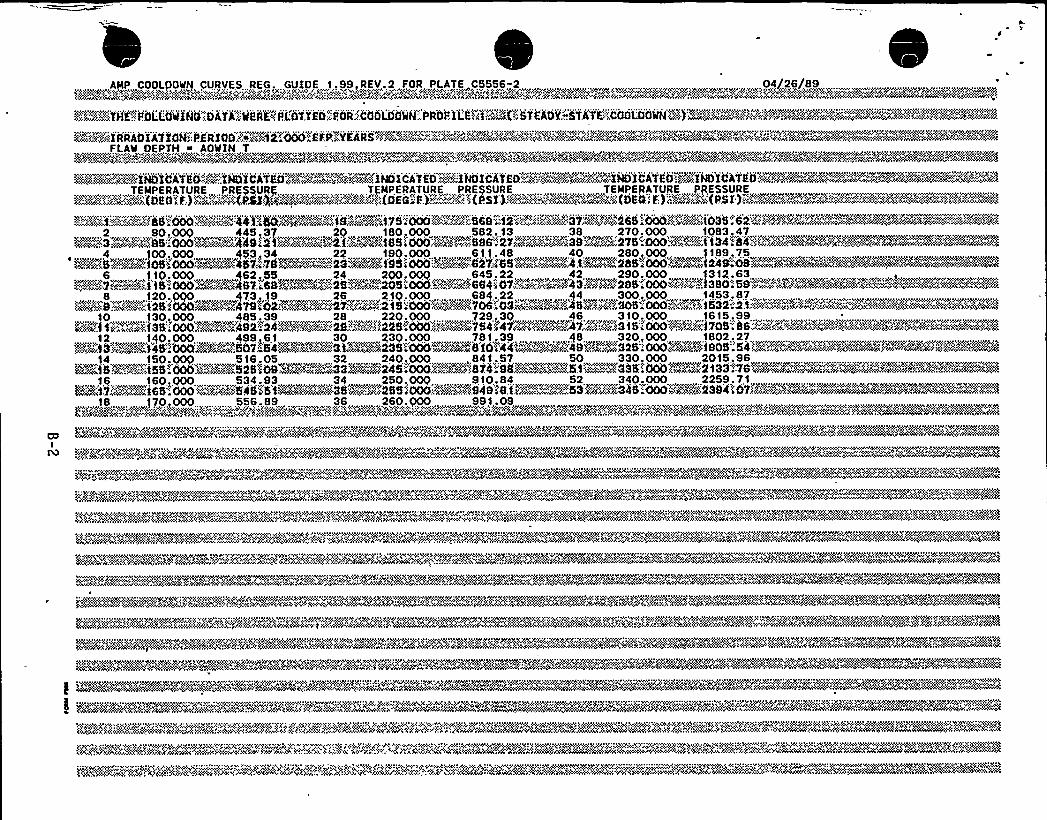

fy
'.r >
lg
jp
tA,

AMP COOLDOWN CURVES REG. GUIDE 1.99 REV.2.FOR PLATE C5556-2...,, ...„,,04<j26/89~;=~ViHE-.;SOLLaMiN
XrNIrXC?yhkh NX>N> . V S<,Pyk. >c,< ~ N (Cr. ~ ?yjjvv<cr< Sj)vv@ygvhkdyryv< Pe:Wyhh>IrdwvvP<gg wwrrNYYYX<kqgrrX rvwvyw>rvdhyy .gv, 1qjhv<~r,jghw Phw>>wg PPP Xr>X>??vr6wk P vFLAW DEPTH <6 AOWIM TLPNrk>>(rh'(vg'g4ANP '0' 'y',. h><hw'
"heWP??jhow<'VN?k<6@v?<<06 ..'ckjw)v)% I '.vv>hwP<cwd wPSP'0<> vv>'R4<rkNPS
, TEMPERATURE PRESSURE , . „„ „ TEMPERATURE,,PRESSURE , . .. TEMPERATUREvv PRESSURE""':@~9~S(DES F)%F4'>(NASÃwe+~a""-")x~~~a(OEG.P).: r~~-Sj~~((PSI)P~4~%~»~~P(DEGPF)~Pea
%K!'ImWBSS';000hv>04>'wXS $6;56. 67m''~ <","4.'~SSOi 000P <I":4"7"6id>S'%c%i".:." '6i .' '6 10; Mdw %'854 "8jg'<4 "WN":'=-'.(0"->4~":.:y:
1 155. 485.60 27 215.000 678.03
~ 4 100. 41 .69 . w .<.17 vx165 000 v „507 ~ 17,, 29 . „225 000,,'729.94
5610
4 33... 245.000 859.27z'::9WOF)'~%f25',"000M<='"W,:437.':25RY&yhg:;"!'2%~%[email protected]'.'000'~j;kw;-.',$ 77 0566m+,?)):.:94 %, g250;0006k~~;.;A...898'8k@X~ ';.;;.j'::."-'~"'-'>"'~'Wm+'m
10 130,000,h, 443.91,w23 195,000, 594.47 35„,, 255.0000 . 939.63, „
140,~ 458,79 25 , 205.000 633. 19 , 37 , 265.000 1032.25x"P~"~%1 3~>>'~k
'j ..Yv>Q
'0!jk'cjoy'6'hx
4 'ck' >xr6 x >'( g<+vvv 'P. +Xj v, '<Ij0$ 'xj)N g?kj hr'hPh'g 'vhkj' v' N+C~' "rh)">x vh$<g<gN'(g "I v>>w'» wgdxc v)q qyvNO<'gxxrykv>v,. <>k/h$ 6 w<'kpk 6 k(j 'vhvr'.~vccgc >'.)'<N 'XCwx>YPI<>vggrypIS '0?<'?PYPxpvP(wvg'( ~kywNr
~ y( YP? 6 X?X0. r(, P,NwN y(PX >X .c <'g +HPX vk>):QC$
ww v. QC < XC Cw grr vrSN%NC?V jv( w65. <h Pwgh <XYWr<@ >X6ghyyhyg wN60 .vvr 0 vkrww, 0 % wWAMgP?X Ph?W g:rjv+<v< vg. pr )X X...+$YPXvPyhN<gN6$ 4>v<CP < CwhNPNSX<P?vkkycwgh NXQ
X XC<PN+<PNC>N '( <0 YXNv<> 'C<rPXCXCSNPN>N<vPS hNr''Ch':;:C.:gk<'P: (X'hj g>C)PN<XPXXSYC:: >',:X XY>X .6<?6 .CkcgkN'F(N<N CNPC;"y '"'X>kk'd<yg'$<k<gXWC Ck 'PYP"{"'gvd.'CS5 ?gNjy'C(:%'(XC(Ng>?)?. XNg<kvd<+F>YAP?rk()< C <YPYhPQP>CNr<>.. N%5yg()VYQS~Ch~k', .jNW~".jwcc'>&W,r'<g~'Scjc~grh>> 'VW>~<$+bgPh?j'sdvx":?j.
hvyP < v W ( yP WXCPNy Pj y)Wrh '(<jXXX S?0 ' h'C 'rP jw<ydkh hy 'khy v~PNr? SYC ydrc>YN>v kg< vPN~wN Y VWNv*crW~Skk YPP. 'XNX&wvN'PrXhy(h)Nw, ~X, 6XjrNXNyv r)w +~ 4<rr<XC<hy wA'we%«hgv"c~x' 0"~+gw(kVYk ": ~vvp'4'~y::"k()x ()<<M~'jc<NRja c~~y"" 4'' x "~a: CPM.<>jpxxkNd ~%jNY"~p "~MgPN~P<'r'<Pc W4c
,yXrrVP. VP VP N 6?NS YNP VXV<W, hkg<N<rj (Sjj'<jay hk>XWrhrd<rrjh'j?y)X'w ?VSX (6 «'y' <rPXj?h>>PXhjjd'jr?X?j <>> VWwhj ')NC NgC> 'hdr)YPY <X?0)CXV'rr<chgjhr?Vj> 'h 6$ (h.' 'j<<>hh <VNXCkr
'?(j X <j<r<cghN<jj <jW(CC ~N 'C>P~r ..<$ :g<6h<'.
i~WC.,YVY,Y~V>hjckhy@SP<YVPW<<Vhgd SWrhh
'""«'"«"~"'-~~":"-::"::i': ","' h'x
X»"'?S
'r< vrh6'.' YI 'crrhgx>NN<h j<h< '6 '. ' 'N ' ' jhw)xjrrhg<C v VI>wrj wpy j 'r 'h v I)g' whwjh<)NN<, vj>?x v jpg<>vk'j>vc<YQ >I ', wfrwyh?'6jh)hjN 'vc vvr<)>xcj>vs ghw
''+v whkr
'p' >Irg<vp~vhypvhhgvg(vdyc v<hv xh'r(r, v IrScjryg(vvxrgv q)lvpA)~'XX.X~?""-cQ < g>'S: Mph'
Wx46>»' wc>pPI"" "(<w~mCx(:g('I"'w.k"7'~Xh'SXCC '~XC Xvdghk'Sjdkr<<Nh'gY6NSghv w~ wC'jX<'."..MNN'kI?XXY>YQP<?V<jkvjkg<g(gNPYC<vrP< ck. NN) XPYNP(hNhc'~'C(Cjk)y'vgr~~P jrr SN ~g<N'?y<'>>P~~)(XC<jjk'."vW+:,~."~>>> ..'..<CS.+'Xk'(Y(y'g(g><cv>jkkkg. '~CXhj<kjgj<?j<cdhy>X+g(cwvjdkv'S)Y4''""'"hvjr<CC@v<@" '"''4 ""hd'Sw'0< ')r'<(< VPv6>v1<h '4p ~Cp k<('r<>66 "ww'Sh"Q.vh<(g?~C'+SC(v>vyhdphg><wk 3~&>hrw~vN(XS:;M(gr(v4jwwkyydgc>w<wckvrrck(drhprhk>ACN<g6kew~d>rrrp>h<)%g(Phd+ pjk@%~j>%?cd>r Pprk
,, Nrpydwc)»chwpy, h?x N vvpwcp>(vv<N<»4< vr6 . >x<hdwcx<x)hk'>v>xcc 6 'Njwwhw<hsh, rpyN<w~w'?wvwr... 'x'cN. <0+cM':?vp '4'PYSPx0xvShwjw N' rj cc vN<'gy??N<ycv''x'p? '.<v'...wdxccjypwyj'~?>>N>xcr~N'jj?pNpp j)pd".xr " . %xN<yaRNP'~Oh..
YPV>NXrNPYY CC Xh 4YXSYPX. yPX vPN'6 hr Yh'P? >X<vv~'<<"""SNYPSC> P(kj'j'0gr hg<>4 <P(6<6k C < Xjvcr >64 YP. <1kk<<PS)+ MR(<'P ( 'k;??XP Nfl>g(.'Ni4%."".: X> . 6 ($@hr<k?4'&44$ wh:: >X(:. 040((@(." PSALM~~<.
w <ryW r V YC ?<her<> >Crrh YVSWC(c. X<h< ~W>4<<(e ( <mk r<?c<h 0 Prhyv WP P~yk PP XP6SPC>z~ P> y( < S(<XN NP<PQ?~6k'VYYNC~rcrr<y(CP Cr gj yr hjr<V<P~PX>N~<kW?~<<<0
y. N(j'g44i@~@w y~ 'S~PC+r'~y.;.? hhjy(
vdwwp rr '0'rcrrh NA'w'(>)hx xYcyccr c ywd'4 .x Yhkpvvr<rr<h )v<chxcvy( ?whycvhyh'jcpk'rw >Y cwpr <pc vkc v r A yrvhhw~~h~ ww >wkc wrc? c x <y?N hgdyh'hxrhvAQ 'Qvh p w }vyxrprr+~vwdw y ~~cwh> N Mph?'@Nil Vg, vs L >(wj6(SPw gj X' ?w ( r( rhr y h@4vA > 4 +@h4g4 4%C g<>@V<6wkN Ai@c: 'ANv4%whAvW>k ( gy)r<r Yvkv vy vkjhd)WPN 45 wPr~yyhd vhVYNWwhNC PC><'CC?
.;:.'p%:- 'T.. ':.'.":".- ')Y h:»-'. --".. v h> "- w i h"." 4',t „Xrh''-,., 'c>'."',„'+.„'.y:.'%h>0>'-'"w: ;pp:: - -,<r----vc;:-,--.„-: i Ix,--
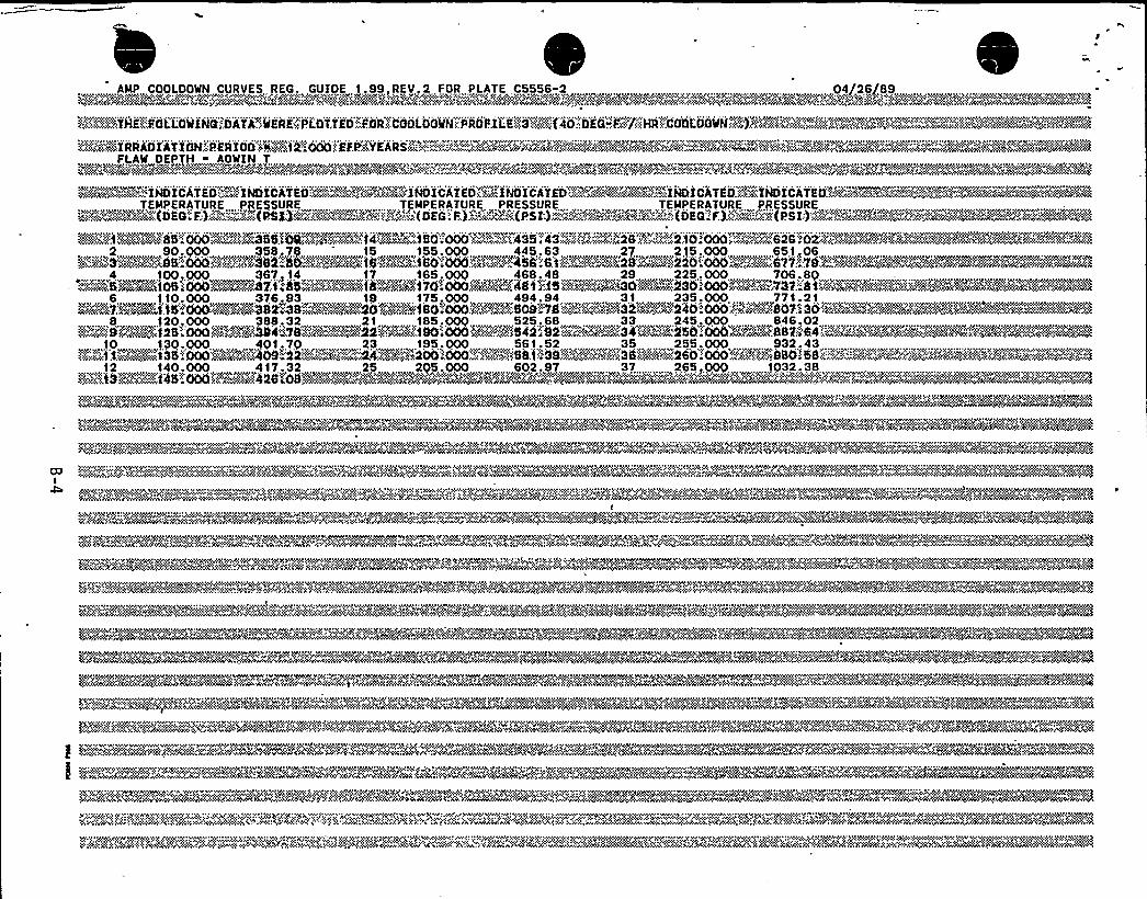

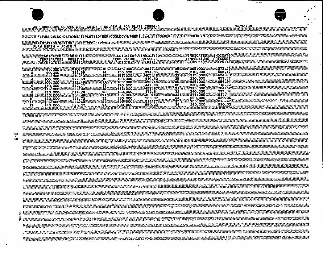
4
l l
1
~C
$ 1
1
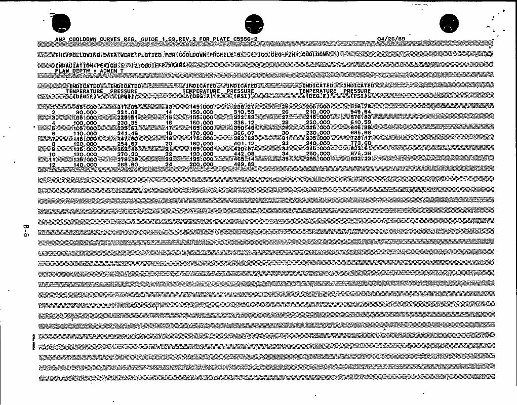

' N
l I
f
J
6
ii


I
CP
'1y
E
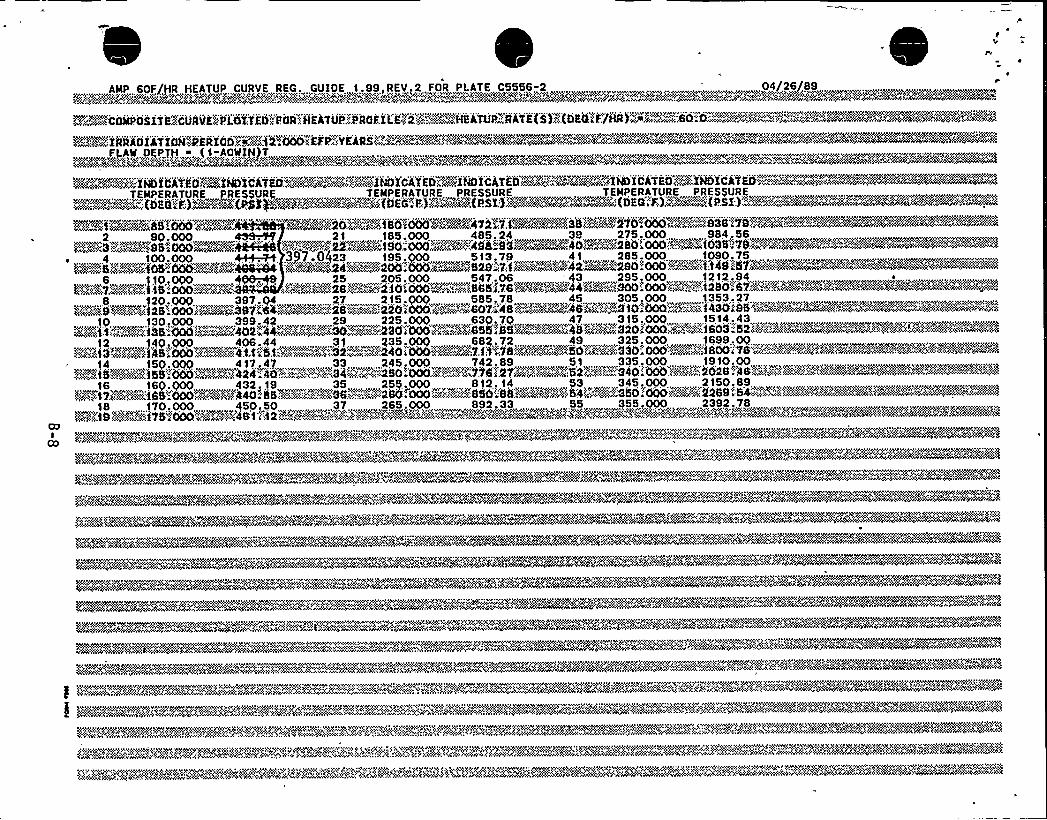
AMP 60F/HR HEATUP CURVE REG. GUIDE 1.99,REV.2 FOR PLATE C5556-2 '4/26/89
><»r» Xg~r~%»' c > C .g . '»y «$ ~C<<r<'. y < '. pre '~, »'M.,'<g r< g»r y .>>. »vvyyc'u".c .y">'e rg'~~~~>~v~~p~ YAm+~v''~»< ~»»g>>y<r~rA~K~». v<<y>»C > y>~,,yy~»., »» .,>~~%~ v>y>y» ~. 4~+~ ~k~~y~<~™~rv~<h c y: »~yV» v< g ~<»&%~X&cyrkr»>kk~~Q~< kahn&/44FR > dNRC>'K4~'>»<>~" >vSMvv»> .1><5 »I<'v'9 >» x&m . ZN '»<vv'»'»i<>» ~2~><'Mk'$X»>c<cc»»~<>/vcccv>i~<»»N'~'4A«. » '» i~W ~@4 ~a'.«Am» '»v» " 4A'4
TEMPERATURE PRESSURE ,.„ „,, TEMPERATURE PRESSURE„ , , TEMPERATURE,PRES$ URE
KPDa)RKi.M88
~,....4v 100,000 „~-,V+ 397,.0)23,, 195,000,513.79,,41, 285,000,, »1090,75„„'„,,>~-:S"'~»: 'aS" 000'~-"'SPA@,-4i: '>)~%~W"'":":-":~2':ee':-'- "'=-529 "VI'-"='~%42~»==: ':290'OOO:'--"': .":: 'I:149."'SV~~YMN~'~:~ '~'= ': ':K%%%
12, 14P.OOO „406,.44, v,» vv„, v31,„235,000 „, „682,72. » „„49v „,325,000 v v1699,0g
0.„50 . .. ...37 .. .265 F 000 892.,33 . . .55 , 355...000 , 2392.78)»v~» 'I9 RAMs~fS;000'"'"' "481. >' 2'" """+<""'>4'-v»y>'"'»»'(+"wM'5"»"sw 4 '%MY'»%i"4%4Y<Yo<44~+>»»»'c'>yS»i+i>r~'y~>rv<."p'"'«'r>%K448<yv cv'444<q >»<Ny<4<<>d'>><N~vMki5%2A
,,„.go<i>„~F~~~.~-;0:; gi;S;:,"WAAR".P~.,QW"g" Mc".,"
3r<rvecyYH+»>»c>$ »»<MKa<<»c<gr<(û<Y>'; C»>~», /<~ay.'Qy.'.V<>Q'iv'V'; >v<<~ "'~+~'v'< yvy~v,.~V;~p<»v'4+@%'pipe.'+pgy"."Ng>'c'py+>V»@N~<%nRy,:..v:;.".yy»>'»ye »v<>gp<r+C>yy~y. t»k
" y . p' ' " ' ':".: '""@TERY:. '~V'5'Q~y>SS~'-"~v." "">"S"":.".vi'4'i'"'IQA%vÃ%4%@~45@%%e%FPw~~vase
~ mt»>,~r>»»>»@4~~»~
,e>v'-:"': -.=::""c"- '~ 'r": ('e-'"a"-"'cc'v"'rg<>ccvrgvgpVpgf'rrr»%c»c'2"'"'<c'""""-""c CÃ%»'+Cgr" +pÃi4%%
~%- <%Wee"~~~vc: y'>K'' 'Y
'»c.~V '< cc .mUi '~ v ..>MS~>ZiZ>~ v r ' wr:~V..r.v»<v.'.>. <r M. »S ICy«>y<5~ irrv r»»>rviv ' rc
CV4"C&ZC'~~Ace»»~Z, '~%~h'><»: »r'i 'K. yyr»>» V«.c~>> ."'~ '» ''.v .>r.:. r;„: ' ' "~» '.~, ~ ~C ~'. ','v' .".5 >,c.'» r
C
v y v,<<» - ~>
~ <cv'>vprrv» "r>v«'~vg'<,'rr rrvCyvcv<vri'<rrr»<rg» < > ~v<c.>y v~<y'>cry '> p V y> ~ pcs v gee»'cg~> r<c>%>rv<vi<r'C<»<>ccrc'>rv>»y '>i»pg'<
'+i<<''.'„-v"
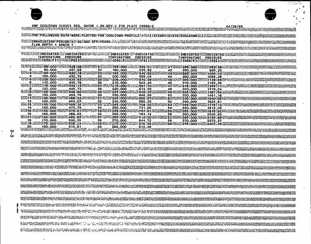

A
Sg
,0
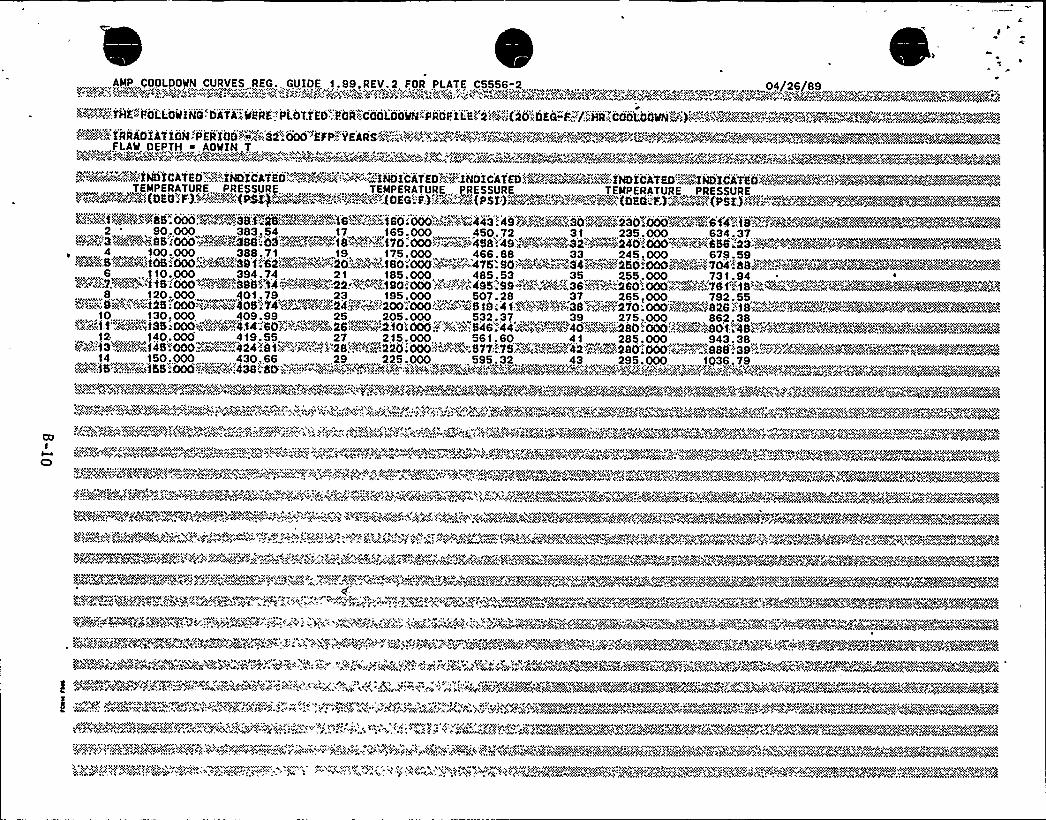
AMP COOLDOWN CURVES REG. GUIDE 1.99 REV.2 FOR PLATE C5556-2 04/26/89
$>v(ry('~cy'THKwy>FOL>LOWINQ"DATA'+'QERK"'PLOTTED 'FOR""COhLdQQI'(PROFILEOx'2$<P(20<llKGwFy''/'RgCOOLOOOWNR<')"''w'>'>r(?4'a@@$ "?'ggo'c'"g$ Ã4q<"c
FLAW DEPTH is AOWIN.T,...,......,,„...,, ......... a„.,„. v,v„„... v~„w- ~ rcva'.*.
~$":=;»""-,';"=".,~'~INDiCAT'EO.'..:;:;.iNDICnEO'::.=-.."'%gal'O'.::.":.'Y-.."I'NOI'CA'TEDDY%.",INO'IC'AT'EDPZNR~"'~""=:"iNDiCATEu'::=:--':I'i'e'ICiT'ETEMPERATURE,. PRESSURE , ..., .TEMPERATURE,, PRESSURE „ . TEMPERATURE PRESSURE"'«"'::""-'"."''( '< ).."'.."."' $"'';.'"":"1"v-'"'-'-9$::-'"'""''k "'.)'.;"'>.". -''i( ')4 ":"'""'-'"""-"":""'""".'5 ': ''"'"="-" '0 )'" ""'"'-
NÃC@KPV."'$125.000FYWSS'>VOSS!" ~X>>'- "1"0.<f *"'""1-2'0:OOOO>C'< 442 49<V'>'>SC<:.SO:"i"„.";::*!l220<Nl''::".."""'". "."S<v(::CSa:!."*" "Wyar>v@2~0+'+'%'~~C"%k'-'"'V>..2,, 90,000„, „,. „383,54 „„„,17 „... 165,000, „450.72 „„231, 235.000,„„„.634„.,37>i%24'3@a~P 895 4000a>..>iA'3(N8'»'05>s>xwx>>4 >wyl 18avc;..~.;.vf 70 000 "Pxc':~c >458 49~x@XOOkaa>32&?~>P'<~i 240'000'ay'" y<?$'4658a23
~ 4 100.000 388.71 19 175.000 466.88 33 245.000 679.59
«WX;77K<>kA"I45';000 ~x> .~ix398';-.':t44'."'Pe=@%5422 <4;-~" "1902000;547>,'.4 495. 99'<4? I'+&%~36~~(>(Ã~:;260I000tvi'.4O>-""76 I'a IS'~~>~~v''XBMFZAX8 120 000 401.79 23, 195 000 507 28 37 ...265 000, 792 55
61x''~9 wr a>~ aa%1 25; 000 >1>('%~~~a'05 "74%'~Y''('>Ij'y"'24-:.'>~ '200 4 000".'>aa> x?5 !9 4 14%(@grj(N!238.'v'~~i'$'"270'.000 >v'"jpxV>'828.'1$ ~~>. x'.X@V< "057~NOVRk~~gB~@S>'>2>.,10,, )302000>, „, 409.99 x „,„„, 25, „,.... 205.000>w 532>37.. <2„„39, y 275.000 „„,862,38@Mt1%RC185'-'DOCILE":$
4'Y,".'@f4'«'60""""."..""'AV.'28:(.""".
,12 r „,, 140,.000 419,55., „.„„„„.27,„, 215.000,, 561.60, 41 „285.000 v,943.38w,14,, 150,. 000„<v 430 <66,, 29,„2>25 >000> 595. 32,, 4,, 295. 000 v,1036.
v> 0> 'C j » >C Oa ? 2<a 1 ac< $L< 'c i 4''4< '~r -, ', V >P Sa P ',, 4 2) 0 ?< ' ) >0 % 1 >Sa 'gvra j+ >vS><X r>> >$<va< >2(4 'g wv '(vr $ 2 $ *>C r ( > ?v>X>l> 4> aa <2) yr( (X<v 2 >v) SX Swav<$ hvjy w(a>Xwr Jrj( ( air g'yj Ow? j?2
g cwwa»w 'v r+>>vrg~r~xw2 "P<P'$'<1>PP'Soviet .c rx "a>44v jr! Xv. ><< a?Oa w 2>«<'>ac jrx <xrc>rv y r ? 2 ....<1" r'( (yg<cc vt" <P'crx < ($ 1<vx( a'„%>x'>><irarr e<w<vo v, ww v r'wxx2v w>4 xxocx wwccy?ax(ywa <e?xro>ccc~vq <vavrc rr rwx<w w<( c<gcrycrwP4. r'4Vv'y< i'4»w'wYTO ':%4'rv ('???xc 'r. '%'% x ">1 ' "4 'yvac'carr'hvc'>'>4'.: 2 aSa>O r."."1'"Xw<".,$> <Xl P>ad'OS?'? Xa>>>'P>C<$>a Xv
1'<yy™g+>4 rg "+r(av> vaXry X >$(>XX <»wa<OX»ya+<vv.,c4. 1<a~ <y $(<(X<<V?)>» XS>>6<a>? PQ(>v <<(jjly<vark $(XC>OSap» g <X>N vjavraa<X<(XC?>XC>X>wj(rj<X. valrv4(XXXÃ C (Ca< cjA>>r>a>XC(WO>re>r>$XP<r>(X>>X>>i*X?vP(wc>&r?v jr>'PXr ?CX(a$ $2 2>PXCOPP>>
%$; .gw? '<g 'jg <.vw'$'4<><.w '%4 >x;,OP<a .:: 4>$ '>Xv: .Cax'$ c R%2 igt$(r'<4>y44~>+PcyÃv, <xrr <, c> cyv'."oc((xvw:Pr+yjccyPP4'Ox+!x<c,'ccc>jjya;Sw<Y$ ~~vg jx+zi„a?jxx Xy'ccxaxy:?xaapx(.xa$ :a~<wy~g"5 rgvO~vjvj $('aIv+s($>rs(a<cx<x4vjyrvcx>w
)"WIXXq™Z,~, ~g>'xx(yrxv'~~<%)x„??ax>>@+ay, „':jay"".(ayXxY02$4'v'g( >?>avay'caa<'a'SXC'<y>(XS "$<(1c,'? PvY jyvgc"ay(>>$>Xaxx'a~v'x2agqya~i.'SO>>>~pa':,xa>q'r'c:.wjeg» .'I..'XvrayZg@@FÃ4@a12(@%a~>j4Xy>'?>?aXv4'N~~IvP~%+0
,"'' P>~'..: ',' >v ., ' >'.. "; '.-:r ~?>>$ 4',> j'<„':4 '.a'4 ~ "w, '.'> " 4" .> ' '>...,"'"" ':," 1<'.,>a> 4 Y,.:vc ': ~ '< Xv,'aa'g,~ „rx? '.;, ."wa>m „„". 'O>>X<(0.spy> gr?6>$ $O%S< <'<(<>O+ ~ +Oay ~ <X ->ay w>01>xa('QS<>vO> -Pry? <Wy< ?.($ , <> arC, r< -ri +42>WC(ii>w$vja < X>$ , „gvd{g+V<V>PCxv'av>$($ $ '<Pjy<Y PPPar'(>V w v Ca(>Crr X r 42>".v'Carhg g (jav(ja(>(X<?a(PX(tCW~$>w< Wwy<(1$(,,V>w(>rgb
Fgjjxc(?>.g(xw>~~@X('w>%>xpacwxvv gxx g.~sara<via,:gP>'wxgw~w~9Avwvra .~+A~)xpw')OAa$'7(c)0 a4$ 4 ($ gx>y 1. +v>yr?v'v+<'PP"lg"<24$ xvg>$$$ 4 w4wyx<yy ..>'x2'xxjsysvvx<" x$<)v((((>yj <>>g '>aP<Qww'hpvx<x(a@px'Pxcxcpwy~yvx<2>c>?yy>yc 'w>y 'wwc O>4>avj'4(4 "'2 rr $<"..".".<x<(;%<4" ><<
'"., xp'x< ~'."':" »"' '( «0'. -> ?a'AO w'~>Aww(a '<' $ ~O<($ ('j'C4a>v<va<vvc YA i vv'rv'va(cw'w'4%M8 r'>a'i%N+x'>?'$><$Xw>Xv$2?r>rk?r>CZ~'Owar'Sar vM'wQ%~~4wwcj KC
.?4'CX<..... 2 OO8'h>ara» ~VS> 'i0?May: " '>?".-."'-~":$'aj"=>Par<". '1<'2'.:,. >12y'CCXAQ'»CXV?i'O'C+" 7?XAW<k'$YSPYC 'C'FXXaa'Fjc><SCM>>CO?2 2?>. ~?C>l aC'PX.'$>a'X"'.;W'ja>$ "r> 2$ 4'%.$ ('X>VCX(&@+'M>>$68<2'<C'>$ 422>(4($ Y>V<aV...QQX'CCM
Op'> $$ '$'gY>"PX'c>v4$vM'XC<v>r<><aavaSX %War >awv'> 2 >+> <,0 ( <rr>>+ 0 va Sa a<C, >$<g > ( . vvwv >xy:- y! vaw .>xWjalr >r><<C> 1(C(vvaiv,.;:.9~*Xv:ravX.rr y ( ry. y - 'ry>v. >> . w'p;::--;--'<r"-: 's::-'.-':-'r:-::-,'""''i":::v ~ ill .«'y.''y.'>40->cA>y.;>.i;.»': roc>>rv".'.;:.""1>@>:::.:ii>"'.:::.;,.a".;i":"r.::.<>::i »1;:rrp',:::":'„:.:'wtyON,.-, javcvaps.
2 'a? A~? ~cc F $ +g Q @ g ooc $$'g(c'v g2x>@ ggpg>ac ) 4> y ( xzp y ?g +x (. +g y+c +$ cj+p~ w
~ > <Qgxgav~1xwox++? 4>rwcggvya<4 gv(2>w4> cw> wavy*'~w
At4 y<y "MY '8 r' ' + '"'. 'vg. av( 4+: jv «<2$ >c<w,j +v. ?' ',"j jQg<+) ~ yxxaa((rat~!8 ?4 Qc?+Op~qv, x>wxE@r. g r,$$ vlcc
--.'. ';--.:;.-;., ~,:,,'.: ', *-.'..-.:-:-Py'' ' ' " " ' '': '.(Y4?",'1?'a .."'a>$ >< > . v',c,'",A'"%A. "44<y»a(XX<X>wccj<C>>XXXSXSXX>w,:,:,"v>v4vW.XgvxX;r . v<v<$$ ".j<'42>XaU:. XS,-.XXxXaya~av+v>w viaXa „;r 'i"'pja? aQ'"i4?~x$ <
,VX'a0 . ' 0 2 > >' <'< 0 $ > 4 < ) <? Xv5@>>< >C?(V 4(a~ 1v> HPr,<~~jag:,Syj.'<$ ?v~+» ~ v C rv WSC . WP('gy~OV SC XXX+>Xrpa>aaW ~X(r~ p~~~
v K'4 ~ ~ Cjl$(„',>rv>$'s? „',.r'. ", 2','2 'Oj
<1($~<'~N 'P'~'POX 'i %h ci> x Ovi v'p<; . ': W, ' x Q<w,y y(, >2 'wg>vSy x?~<X>'>, <(x rpya.. Ov,, $g >r>o 'g 4$0ya4$ 2W? 1>v xrv vav

W
P
( l
~'i
v J"
F
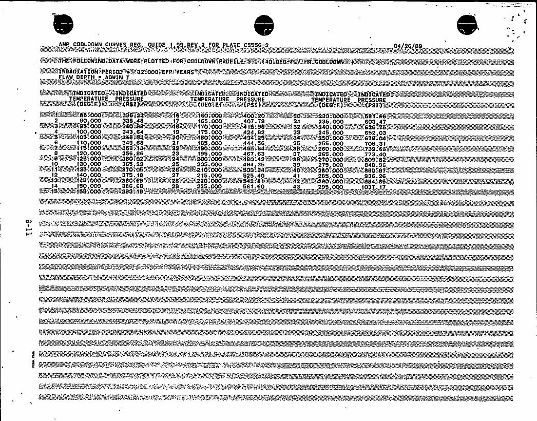

peal't
pf g
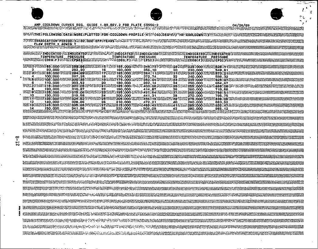

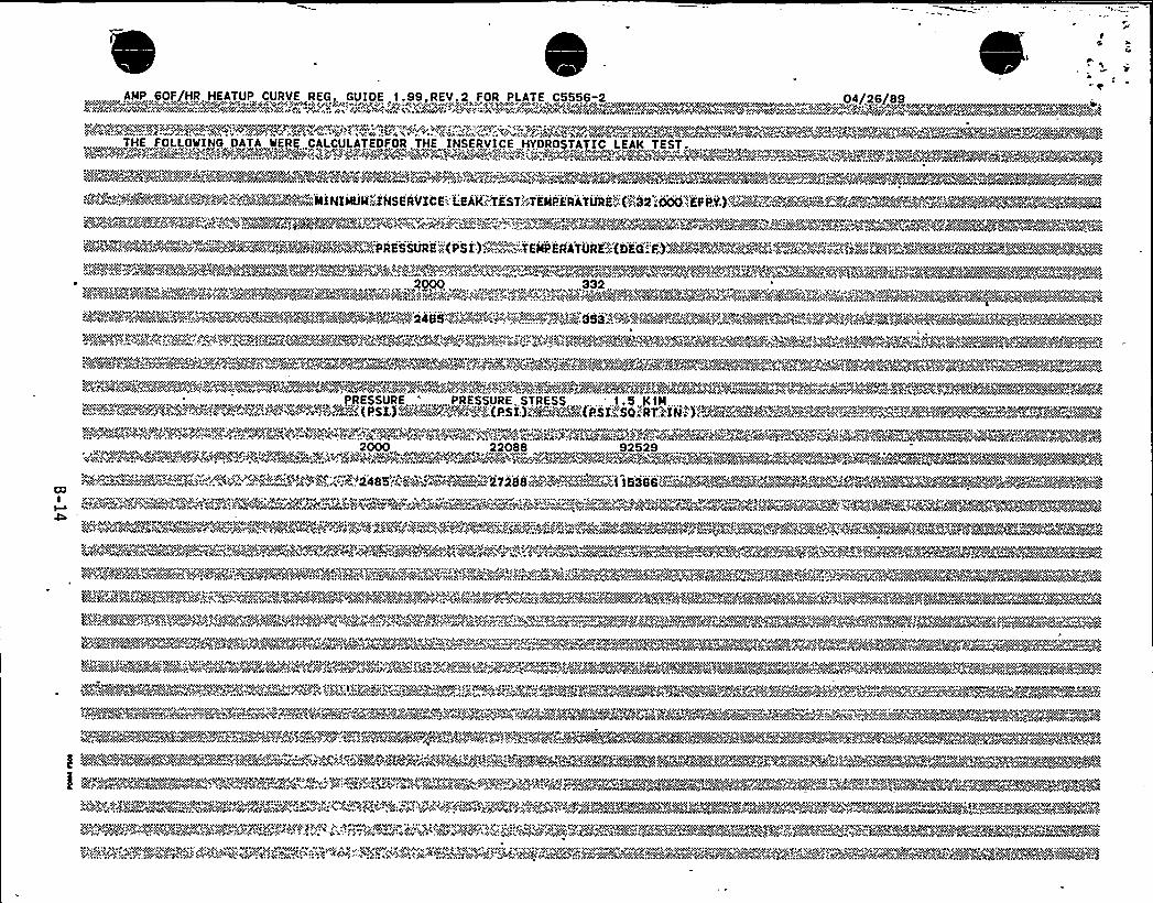
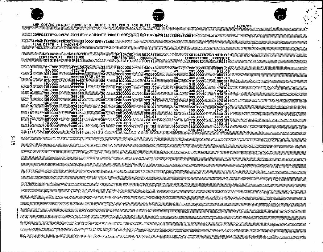

l
Attachment 1 TO AEP:NRC:1077A
DESCRIPTION AND 10 CFR 50.92 ANALYSES FOR CHANGESTO THE DONALD C. COOK NUCLEAR PLANT UNIT 2
TECHNICAL SPECIFICATIONS

T
Attachment 1 to AEP:NRC:1077A Page 1
DESCRIPTION OF AMENDMENT REQUEST
In this application to amend the Donald C. Cook Nuclear Plant Unit 2
license, we propose to revise the Technical Specifications byimplementing a Core Operating Limits Report (COLR) for Unit 2 inaccordance with Generic Letter 88-16, "Removal of Cycle-SpecificParameter Limits From Technical Specifications." The proposedTechnical Specification (T/S) changes are as follows:
Definition 1.39, "CORE OPERATING LIMITS REPORT," was added inaccordance with Generic Letter 88-16
2. T/S 3.1.1.4, "MODERATOR TEMPERATURE COEFFICIENT," was revisedby removing the cycle-specific moderator temperaturecoefficient limit for end of life and placing it in the COLR inaccordance with Generic Letter 88-16.
T/S 4.1.1.4.2.b, a surveillance requirement for T/S 3.1.1.4,was revised by referencing the 300 ppm surveillance limit inthe COLR.
4, T/S 3.1.3.1, "MOVABLE CONTROL ASSEMBLIES GROUP HEIGHT," wasrevised by removing the reference to Figure 3.1-1, "ROD BANKSTEP POSITION AS A FUNCTION OF POWER," and referencing theCOLR.
5. T/S 3.1.3.4, "ROD DROP TIME," was revised by removing the valuefor the fully withdrawn position and placing it in the COLR inaccordance with Generic Letter 88-16.
T/S 3.1.3.5, "SHUTDOWN ROD INSERTION LIMIT," was revised byremoving the value for the insertion limit and placing it inthe COLR in accordance with Generic Letter 88-16. The T/S wasalso revised by changing the phrase "fullywithdrawn" to aphrase that references the insertion limit.
7. T/S 3.1.3.6 was revised by removing the reference to Figure3.1-1, "ROD BANK STEP POSITION AS A FUNCTION OF POWER," andreferencing the COLR, and by moving Figure 3.1-1, page 3/41-26, from the T/Ss to the COLR in accordance with GenericLetter 88-16.
T/S 3.2.1, "AXIALFLUX DIFFERENCE," was revised by removing thecycle-specific target band limits from the T/S and referencingthe COLR, and by removing Figure 3.2-1, "ALLOWABLE DEVIATIONFROM TARGET FLUX DIFFERENCE," page 3/4 2-4, and placing it inthe COLR in accordance with Generic Letter 88-16. Surveillancerequirement 4.2.1.4 was also revised by removing the values forthe axial flux difference target band and referencing the COLR.
Attachment 1 to AEP:NRC:1077A Page 2
9. T/S 3.2.2, "HEAT FLUX HOT CHANNEL FACTOR F (Z)," was revised bymoving the cycle-specific F limit from th9 T/S to the COLR,and moving the associated figures (Figures 3.2-2, page 3/4 2-8,and 3.2-2(a), page 3/4, 2-8a) into the COLR in accordance withGeneric Letter 88-16.
10. T/S 3.2.3, "NUCLEAR ENTHALPY HOT CHANNEL FACTOR - F ~'," wasrevised by moving the cycle-specific F" and its power factormultiplier from the T/S to the COLR in accordance with GenericLetter 88-16.
ll. T/S 3.2.6, "ALLOWABLE POWER LEVEL - APL", was revised by movingFigure 3.2-3, page 3/4 2-8b, V(Z) AS A FUNCTION OF CORE .
HEIGHT," from the T/S to the COLR, and referencing thecycle-specific F limit in the COLR in accordance with GenericLetter 88-16. SParting in Cycle 8, a cycle-specific V(Z)function will replace the current generic V(Z) calculated byAdvanced Nuclear Fuels.
12. T/S 6.9.1.11, "CORE OPERATING LIMITS REPORT," was added to theT/Ss in accordance'ith Generic Letter 88-16.
13. In addition corresponding changes have been made to theappropriate Bases sections.
B. 'BACKGROUND
Generic Letter 88-16, "Removal of Cycle-Specific Parameter Limitsfrom Technical Specifications," provides guidance for relocatingcycle-specific parameters from the T/Ss so that future reloaddesigns can be implemented in accordance with 10 CFR 50.59. Thegeneric letter requires that the cycle-specific parameters bemaintained in a COLR and the NRC be informed of changes to the COLR.
Any changes to the operating limits will made using approved NRC
methodologies for Cook Nuclear Plant. This change will not affectthe operation or safety of Cook Nuclear Plant Unit 2 since theactions required to be completed should a limit be exceeded will notbe removed from the T/Ss.
The proposed T/S changes include the removal of the moderatortemperature coefficient, the shutdown rod insertion limit, thecontrol rod insertion limits (Figure 3.1-1), the axial fluxdifference operational limits (Figure 3.2-1), the heat flux hotchannel factor limit and associated factors (Figures 3.2-2 and3.2-2(a)), the nuclear enthalpy hot channel factor limit andassociated factors, and the allowable power level factors F , K(Z),and V(Z) from the T/Ss. The proposed T/Ss retain the LimitingCondition for Operation (LCO) wording and surveillance requirementsby referring to the specific limits which are provided to the NRC ina COLR in accordance with the proposed T/S 6.9.1 ~ 11. Relocation ofthese cycle-specific limits is consistent with the guidance provided

l
4
1l
C
At)'
\1
l'l
Attachment 1 to AEP:NRC:1077A Page 3
by the NRC in Generic Letter 88-16. Removal of the limits from theT/Ss will allow cycle-specific limits to be implemented inaccordance with approved methodology in a timely and cost effectivemanner.
C. JUSTIFICATION
These T/S changes comply with the NRC guidance given in GenericLetter 88-16. Implementation of a COLR for each unit will allow forcycle-specific parameter limit changes in accordance with thereferenced approved methodology of Section 6.9.1.11. The relocationof the cycle-specific parameter limits to the COLR will allow forgreater flexibility in optimizing designs to enhance the economicsfor each cycle.
D. SAFETY EVALUATION
The relocation of the cycle-specific parameters does not affect theoperation of Cook Nuclear Plant Unit 2. The revised T/S willrequire the same actions to be taken when a limit is exceeded asrequired by the present T/S. Revisions to the COLR will be made inaccordance with '10 CFR 50.59 and the NRC will be notified of allrevisions in accordance with proposed T/S 6.9.1.11. All revisionsto the COLR will be based on NRC-approved methodologies.
The proposed revision to the T/Ss simply revises the method by whichchanges to the cycle-specific parameter limits can be requested andimplemented. The parameters and methodologies associated withcalculating them are presented below:
1) Revisions to the Moderator Temperature Coefficient, Rod Drop TimeRod Insertion, Shutdown Rod Insertion, and Control Rod InsertionLimits will be based on the Westinghouse methodology previouslyreviewed and approved by the NRC and described in WCAP-9272-P-A,"Westinghouse Reload Safety Evaluation Methodology."
2) The Axial Flux Difference Limits will be, determined in accordancewith Westinghouse methodology previously reviewed and approved bythe NRC and described in WCAP-10216-P-A, Part B, "Relaxation ofConstant Axial Offset Control/F Surveillance TechnicalSpecification;" WCAP-9272-P-A, Westinghouse Reload SafetyEvaluation Methodology;" and WCAP-8385, "Power Distribution Controland Load Following Procedures."
3) The Heat Flux Hot Channel Factor F (Z) will be determined inaccordance with Westinghouse methodol9gy previously reviewed andapproved by the NRC and described in WCAP-10266-P-A, Rev. 2, "The1981 Version of Westinghouse Evaluation Model Using BASH Code;"WCAP-9272-P-A, "Westinghouse Reload Safety Evaluation Methodology;"and WCAP-10216-P-A, Part B, "Relaxation of Constant Axial OffsetControl/F Surveillance Technical Specification."

I ~
k
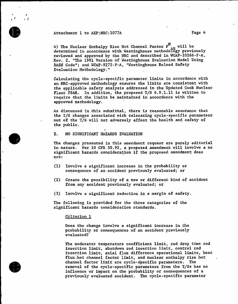
Attachment 1 to AEP:NRC:1077A Page 4
4) The Nuclear Enthalpy Rise Hot Channel Factor F will bedetermined in accordance with Westinghouse methodology previouslyreviewed and approved by the NRC and described in WCAP-10266-P-A,Rev. 2, "The 1981 Version of Westinghouse Evaluation Model UsingBASH Code"; and WCAP-9272-P-A, "Westinghouse Reload SafetyEvaluation Methodology."
Calculating the cycle-specific parameter limits in accordance withan NRC-approved methodology ensures the limits are consistent withthe applicable safety analysis addressed in the Updated Cook NuclearPlant FSAR. In addition, the proposed T/S 6.9.1.11 is written torequire that the limits be maintained in accordance with theapproved methodology.
As discussed in this submittal, there is reasonable assurance thatthe T/S changes associated with relocating cycle-specific parametersout of the T/S will not adversely affect the health and safety ofthe public.
E. NO SIGNIFICANT HAZARDS EVALUATION
The changes presented in this amendment request are purely editorialin nature. Per 10 CFR 50.92, a proposed amendment will involve a nosignificant hazards consideration if the proposed amendment doesnot:
(1) Involve a significant increase in the probability orconsequence of an accident previously evaluated; or
(2) Create the possibility of a new or different kind of accidentfrom any accident previously evaluated; or
(3) Involve a significant reduction in a margin of safety.
The following is provided for the three categories of thesignificant hazards consideration standards.
Criterion 1
Does the change involve a significant increase in theprobability or consequences of an accident previouslyevaluated2
The moderator temperature coefficient limit, rod drop time rodinsertion limit, shutdown rod insertion limit, control rodinsertion limit, axial flux difference operational limits, heatflux .hot channel factor limit, and nuclear enthalpy rise hotchannel factor limit are cycle-s'pecific parameters. Theremoval of the cycle-specific parameters from the T/Ss has noinfluence or impact on the probability or consequences of apreviously evaluated accident. The cycle-specific parameter

II +l e"'I
+I
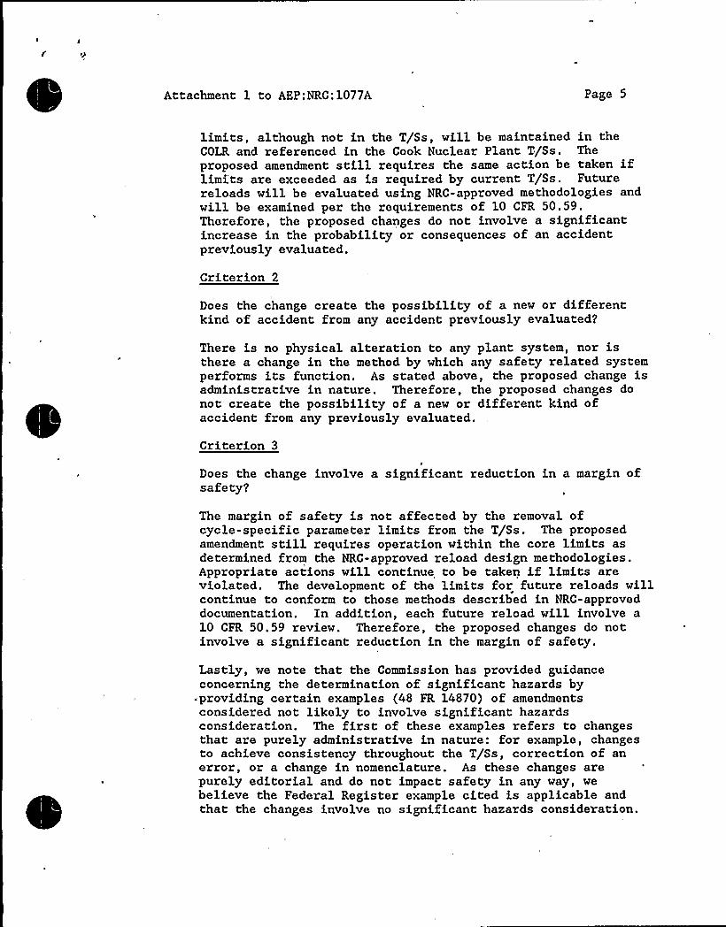
Attachment 1 to AEP:NRC:1077A Page 5
limits, although not in the T/Ss, will be maintained in theCOLR and referenced in the Cook Nuclear Plant T/Ss. Theproposed amendment still requires the same action be taken iflimits are exceeded as is required by current T/Ss. Futurereloads will be evaluated using NRC-approved methodologies andwill be examined per the requirements of 10 CFR 50.59.Therefore, the proposed changes do not involve a significantincrease in the probability or consequences of an accidentpreviously evaluated.
Criterion 2
Does the change create the possibility of a new or differentkind of accident from any accident previously evaluated2
There is no physical alteration to any plant system, nor isthere a change in the method by which any safety related systemperforms its function. As stated above, the proposed change isadministrative in nature. Therefore, the proposed changes donot create the possibility of a new or different kind ofaccident from any previously evaluated.
Criterion 3
Does the change involve a significant reduction in a margin ofsafety?
The margin of safety is not affected by the removal ofcycle-specific parameter limits from the T/Ss. The proposedamendment still requires operation within the core limits asdetermined from the NRC-approved reload design methodologies.Appropriate actions will continue to be taken if limits areviolated. The development of the limits for future reloads willcontinue to conform to those methods described in NRC-approveddocumentation. In addition, each future reload will involve a10 CFR 50.59 review. Therefore, the proposed changes do notinvolve a significant reduction in the margin of safety.
Lastly, we note that the Commission has provided guidanceconcerning the determination of significant hazards byproviding certain examples (48 FR 14870) of amendmentsconsidered not likely to involve significant hazardsconsideration. The first of these examples refers to changesthat are purely administrative in nature: for example, changesto achieve consistency throughout the T/Ss, correction of anerror, or a change in nomenclature. As these changes arepurely editorial and do not impact safety in any way, webelieve the Federal Register example cited is applicable andthat the changes involve no significant hazards consideration.
Attachment 1 to AEP:NRC:1077A Page 6
F. ENVIRONMENTAL EVALUATION
I&M has evaluated the proposed changes and determined that thechanges do not involve (i) a significant hazards consideration,(ii) a significant change in the types or significant increases inthe amounts of any effluents that may be released off site, or (iii)a significant increase in individual or cumulative occupationalradiation exposure. Accordingly, the proposed changes meet theeligibility criterion for categorical exclusion set forth in10 CFR 51.22(c)(9). Therefore, pursuant to 10 CFR 51.22(b), anenvironmental assessment of the proposed changes is not required.

4 e 1
0