
II MIDWEIGHT/PRO-PLOW Series 2/POLY PRO...
16
MIDWEIGHT™ Snowplow, PRO-PLOW ® Series 2 and POLY PRO-PLOW ® Series 2 Snowplows 72308, 72381, 72390, 72400, 72450, 74330, 74340, 74900, 74910 Installation Instructions Western Products, PO Box 245038, Milwaukee, WI 53224-9538 • www.westernplows.com December 1, 2011 Lit. No. 49583, Rev. 01 A DIVISION OF DOUGLAS DYNAMICS, L.L.C. CAUTION Read this document before installing the snowplow. CAUTION See your WESTERN ® outlet/Web site for specific vehicle application recommendations before installation. The Selection List has specific vehicle and snowplow requirements.
Transcript of II MIDWEIGHT/PRO-PLOW Series 2/POLY PRO...

MIDWEIGHT™ Snowplow, PRO-PLOW® Series 2 and
POLY PRO-PLOW® Series 2 Snowplows72308, 72381, 72390, 72400, 72450,
74330, 74340, 74900, 74910Installation Instructions
Western Products, PO Box 245038, Milwaukee, WI 53224-9538 • www.westernplows.com
December 1, 2011Lit. No. 49583, Rev. 01
A DIVISION OF DOUGLAS DYNAMICS, L.L.C.
CAUTIONRead this document before installing the snowplow.
CAUTIONSee your WESTERN® outlet/Web site for specifi c vehicle application recommendations before installation. The Selection List has specifi c vehicle and snowplow requirements.

Lit. No. 49583, Rev. 01 2 December 1, 2011
SAFETY
SAFETY DEFINITIONS
NOTE: Indicates a situation or action that can lead to damage to your snowplow and vehicle or other property. Other useful information can also be described.
WARNINGIndicates a potentially hazardous situation that, if not avoided, could result in death or serious personal injury.
CAUTIONIndicates a potentially hazardous situation that, if not avoided, may result in minor or moderate injury. It may also be used to alert against unsafe practices.
Instruction Label
Warning/Caution Label
WARNING/CAUTION & INSTRUCTION LABELS
Become familiar with and inform users about the warning/caution and instruction labels on the back of the blade.
NOTE: If labels are missing or cannot be read, see your sales outlet.
Lit. No. 49583, Rev. 01 3 December 1, 2011
SAFETY
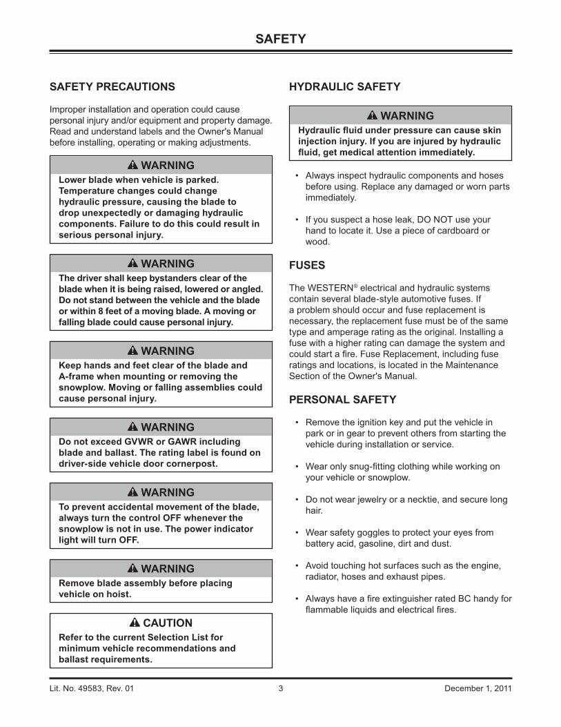
HYDRAULIC SAFETY
• Always inspect hydraulic components and hoses before using. Replace any damaged or worn parts immediately.
• If you suspect a hose leak, DO NOT use your hand to locate it. Use a piece of cardboard or wood.
FUSES
The WESTERN® electrical and hydraulic systems contain several blade-style automotive fuses. If a problem should occur and fuse replacement is necessary, the replacement fuse must be of the same type and amperage rating as the original. Installing a fuse with a higher rating can damage the system and could start a fi re. Fuse Replacement, including fuse ratings and locations, is located in the Maintenance Section of the Owner's Manual.
PERSONAL SAFETY
• Remove the ignition key and put the vehicle in park or in gear to prevent others from starting the vehicle during installation or service.
• Wear only snug-fi tting clothing while working on your vehicle or snowplow.
• Do not wear jewelry or a necktie, and secure long hair.
• Wear safety goggles to protect your eyes from battery acid, gasoline, dirt and dust.
• Avoid touching hot surfaces such as the engine, radiator, hoses and exhaust pipes.
• Always have a fi re extinguisher rated BC handy for fl ammable liquids and electrical fi res.
WARNINGHydraulic fl uid under pressure can cause skin injection injury. If you are injured by hydraulic fl uid, get medical attention immediately.
SAFETY PRECAUTIONS
Improper installation and operation could cause personal injury and/or equipment and property damage. Read and understand labels and the Owner's Manual before installing, operating or making adjustments.
WARNINGLower blade when vehicle is parked. Temperature changes could change hydraulic pressure, causing the blade to drop unexpectedly or damaging hydraulic components. Failure to do this could result in serious personal injury.
WARNINGRemove blade assembly before placing vehicle on hoist.
WARNINGThe driver shall keep bystanders clear of the blade when it is being raised, lowered or angled. Do not stand between the vehicle and the blade or within 8 feet of a moving blade. A moving or falling blade could cause personal injury.
WARNINGDo not exceed GVWR or GAWR including blade and ballast. The rating label is found on driver-side vehicle door cornerpost.
WARNINGTo prevent accidental movement of the blade, always turn the control OFF whenever the snowplow is not in use. The power indicator light will turn OFF.
WARNINGKeep hands and feet clear of the blade and A-frame when mounting or removing the snowplow. Moving or falling assemblies could cause personal injury.
CAUTIONRefer to the current Selection List for minimum vehicle recommendations and ballast requirements.
Lit. No. 49583, Rev. 01 4 December 1, 2011
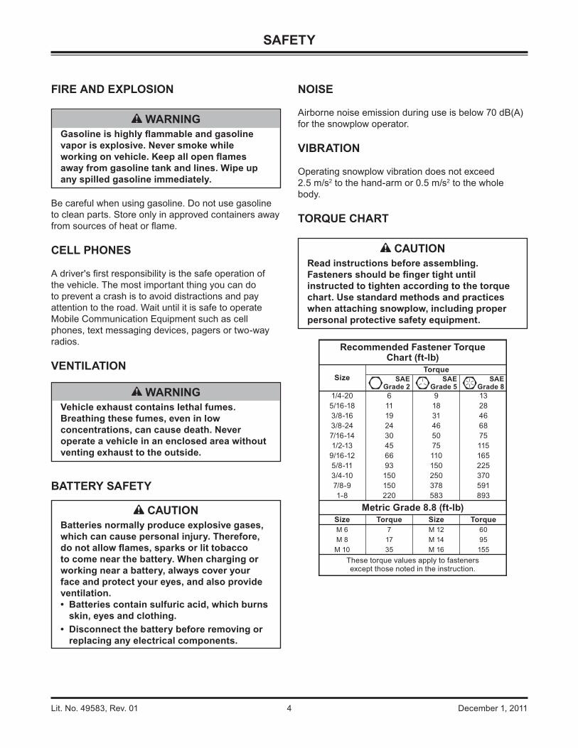
FIRE AND EXPLOSION
Be careful when using gasoline. Do not use gasoline to clean parts. Store only in approved containers away from sources of heat or fl ame.
CELL PHONES
A driver's fi rst responsibility is the safe operation of the vehicle. The most important thing you can do to prevent a crash is to avoid distractions and pay attention to the road. Wait until it is safe to operate Mobile Communication Equipment such as cell phones, text messaging devices, pagers or two-way radios.
VENTILATION
BATTERY SAFETY
NOISE
Airborne noise emission during use is below 70 dB(A) for the snowplow operator.
VIBRATION
Operating snowplow vibration does not exceed 2.5 m/s2 to the hand-arm or 0.5 m/s2 to the whole body.
TORQUE CHART
SAFETY
Recommended Fastener TorqueChart (ft-lb)
SizeTorque
SAEGrade 2
SAEGrade 5
SAEGrade 8
1/4-20 6 9 135/16-18 11 18 283/8-16 19 31 463/8-24 24 46 687/16-14 30 50 751/2-13 45 75 115
9/16-12 66 110 1655/8-11 93 150 2253/4-10 150 250 3707/8-9 150 378 5911-8 220 583 893
Metric Grade 8.8 (ft-lb)Size Torque Size TorqueM 6 7 M 12 60M 8 17 M 14 95M 10 35 M 16 155
These torque values apply to fastenersexcept those noted in the instruction.
CAUTIONBatteries normally produce explosive gases, which can cause personal injury. Therefore, do not allow fl ames, sparks or lit tobacco to come near the battery. When charging or working near a battery, always cover your face and protect your eyes, and also provide ventilation.• Batteries contain sulfuric acid, which burns
skin, eyes and clothing.• Disconnect the battery before removing or
replacing any electrical components.
CAUTIONRead instructions before assembling. Fasteners should be fi nger tight until instructed to tighten according to the torque chart. Use standard methods and practices when attaching snowplow, including proper personal protective safety equipment.
WARNINGVehicle exhaust contains lethal fumes. Breathing these fumes, even in low concentrations, can cause death. Never operate a vehicle in an enclosed area without venting exhaust to the outside.
WARNINGGasoline is highly fl ammable and gasoline vapor is explosive. Never smoke while working on vehicle. Keep all open fl ames away from gasoline tank and lines. Wipe up any spilled gasoline immediately.

Lit. No. 49583, Rev. 01 5 December 1, 2011
INSTALLATION INSTRUCTIONS
LIFT FRAME TO A-FRAME ASSEMBLY
1. Set aside the blade guides and parts bags. The vehicle electrical harnesses and Owner's Manual packet are in the bag with the headlamp box.
2. Remove the packaging hardware securing the lift frame to the A-frame, except for the clevis pins and the red shipping brackets.
3. Remove the fasteners and blocking securing the A-frame to the pallet.
4. While supporting the lift frame, remove the clevis pins and discard the red shipping brackets.
Pivot Plate Confi guration
IMPORTANT! Before assembling the lift frame to the A-frame, pivot plate orientation and pivot hole position must be determined using the following procedure. (If the truck is unavailable, use confi guration 2. Adjustments can be made later.)
Before measuring the vehicle mount height, the vehicle mount and receiver brackets must be installed, ballast must be installed, if required, and the vehicle must be parked on a level surface.
1. Measure the distance "d" from the ground to the top edge of the receiver bracket. Measure both sides and determine average value for "d".
Top edge ofreceiver
d
2. Use dimension "d" from Step 1 and the following chart to determine the proper pivot plate mounting position and pivot hole selection.
Pivot Plate Confi guration ChartDimension "d" Confi guration Stacking Stop
13.0" – 14.5" 1 No14.5" – 16.0" 2 No16.0" – 17.5" 3 Yes17.5" – 19.0" 4 Yes
3. The two pivot plates, A and B, are mirror images of each other. They may be turned over and switched from one side of the lift frame to the other to provide two different mounting positions.
In each pivot plate mounting position, the pivot bar pins may be installed through either of the lower holes in the pivot plates, providing four different height adjustment positions. The pivot bar pins are never installed in either of the two upper holes in the pivot plates.
Configuration 1
Configuration 3
Configuration 4
Configuration 2

Lit. No. 49583, Rev. 01 6 December 1, 2011
4. Secure the pivot plates to the lower lift frame using the fasteners removed in Step 1. Tighten all fasteners according to the torque chart.
Pivot Plates to Pivot Bar
5. Position the A-frame and pivot bar between the pivot plates, aligning the hole at each end of the pivot bar with the appropriate hole in the pivot plate.
6. Insert 1" x 4-3/4" clevis pins from the inside of the pivot bar through the correct pivot plate holes for the confi guration. Secure the clevis pins with washers and cotter pins.
PRO-PLOW® Series 2 only
7. Attach the stacking stop to the A-frame using two 3/8" x 1" cap screws and locknuts.
INSTALLATION INSTRUCTIONS
Pivot Plates to Lift Frame
Confi guration 1 or 2
The snowplow is pre-assembled for confi guration 1 or 2. If the lift frame to A-frame assembly needs to be in either of these confi gurations, the pivot plates do not need to be repositioned. Skip to Step 5.
Confi guration 3 or 4
If the lift frame to A-frame assembly needs to be in confi guration 3 or 4, the pivot plates must be removed and repositioned before the A-frame is assembled to the lift frame.
1. With the lift frame supported, remove and retain the two 5/8" x 2" carriage bolts and locknuts near the thrust tube on both sides.
2. Rotate the stand downward and out of the way until the clearance hole is visible. Remove the 5/8" x 1-1/2" cap screw through the clearance hole. Retain the cap screw and locknut. Repeat on the other side.
3. Reposition the pivot plates by turning them over and switching them from one side of the lift frame to the other.
5/8" x 1-1/2"Cap Screw
5/8" x 2"Carriage Bolts
5/8" Locknuts
5/8" Locknuts
Thrust Tube
Stacking Stop3/8" x 1" Cap Screws
3/8" Locknuts
1" x 4-3/4"Clevis Pin
1" Washer
Cotter Pin
Pivot Bar

Lit. No. 49583, Rev. 01 7 December 1, 2011
STAND SHOE
Initial stand shoe height adjustment is based on the Pivot Plate Confi guration chart. A fi nal adjustment of the stand shoe will be made after attaching the snowplow to the vehicle.
1. Slide the stand shoe into the stand tube and align the 1/4" hole in the stand tube with the 1/4" hole in the stand shoe determined from the height confi guration chart and illustration.
Pivot Plate Confi guration ChartDimension "D" Confi guration Stacking Stop
13.0" – 14.5" 1 No14.5" – 16.0" 2 No16.0" – 17.5" 3 Yes17.5" – 19.0" 4 Yes
2. Insert a 1/4" roll pin.
3. Do not cut the spring tie until after the fi nal stand shoe adjustment.
WARNINGThe stand plunger spring is shipped compressed and tied. Do not cut the spring tie until fi nal stand shoe adjustment is complete and the roll pin is installed.
Configuration 1Configuration 2Configuration 3Configuration 4
(PRO-PLOW® Series 2 only)
Roll Pin
INSTALLATION INSTRUCTIONS

Lit. No. 49583, Rev. 01 8 December 1, 2011
INSTALLATION INSTRUCTIONS
5. Remove and discard the factory-installed pipe plug from the breather port.
6. Install the 90° elbow into the port, pointing up. Install the breather into the elbow.
7. Replace the hydraulic unit cover.
8. Pivot the lift arm and lift ram up. Replace the two pins, washers, and hairpin cotters to reattach the lift arm to the lift frame.
9. Move the driver-side lift chain back to the lift arm hook.
HYDRAULIC UNIT BREATHER INSTALLATION
1. Position the lift frame in the upright position with the stands supporting the snowplow.
2. Move the driver-side lift chain from the lift arm hook to the cable boot bracket on the side of the upper lift frame.
3. Remove and retain the two hairpin cotters, washers and pins attaching the lift arm to the lift frame.
4. Pivot the lift arm and lift ram forward and remove the hydraulic unit cover.
Breather
90° Elbow
BreatherPort
Move chainto here

Lit. No. 49583, Rev. 01 9 December 1, 2011
INSTALLATION INSTRUCTIONS
A-FRAME TO BLADE ASSEMBLY
1. Align the pivot bolt hole on the A-frame with the pivot bolt hole on the quadrant ("B").
2. Install the pivot bolt from the top. Secure with a 1" locknut and tighten the locknut as much as possible while allowing the A-frame and quadrant to pivot.
3. Move the snowplow into normal operating position.
4. Remove the protective packaging from the angle rams.
5. Align the holes in the angle rams with the angle ram holes on the quadrant ("A" and "C"). Attach using the two 1" x 3-5/16" clevis pins from the top. Secure with 1/4" x 2" cotter pins.
PRO-PLOW® Series 2 Blade
MIDWEIGHT™ Blade
A
B
C
AB
C
1" Locknut
Pivot Bolt
1" x 3-5/16"Clevis Pin 1" x 3-5/16"
Clevis Pin
1/4" x 2"Cotter Pin
A
CB
1" Locknut
Pivot Bolt
1" x 3-5/16"Clevis Pin
1" x 3-5/16"Clevis Pin
1/4" x 2"Cotter Pin
A-Frame/Lift Frame Assembly

Lit. No. 49583, Rev. 01 10 December 1, 2011
INSTALLATION INSTRUCTIONS
Retainer Bar5/16" x 1-1/4" CapScrews & Locknuts
Retainer Bars
Rubber Deflector
7-1/2' AND 8' POLY BLADE SNOW DEFLECTOR
POLY PRO-PLOW® Series 2 Blades Only
Align the holes in the rubber defl ector material with the holes in the poly blade frame top angle. Starting at one end, align the end hole in the retainer bar with the end hole in the defl ector and blade frame top angle. Loosely install 5/16" x 1-1/4" cap screws and locknuts in the retainer bar holes.
Position the remaining retainer bars and loosely install the fasteners.
Tighten the fasteners starting from the center of the blade and working out toward each end.
BLADE GUIDE ASSEMBLY
Insert the pointed end of the clamp into the coil of the blade guide rod. Attach a blade guide rod to each outer rib using 5/16" x 1" cap screws and locknuts.
5/16"Locknuts
Blade GuideFlagBlade
GuideRod S-Hook
Clamp
5/16" x 1"Cap Screws

Lit. No. 49583, Rev. 01 11 December 1, 2011
INSTALLATION INSTRUCTIONS
HEADLAMPS
Headlamps, hardware and instructions are found in the headlamp box. Additional hardware (two 1-7/8" fl at washers) can be found in the parts bag.
1. Attach the headlamps to the headlamp channel according to the instructions provided in the headlamps box, substituting the 1-7/8" fl at washer from the parts bag for the 1/2" fl at washer packed in the headlamps box.
1-7/8" OD Flat Washer(from parts
bag)
1/2" Lock Washer
Headlamp SwivelGrommet
1/2" Nut
Cable TieAnchor
HeadlampHarness
HeadlampHarness
CableBoot
2. Insert seven cable tie anchors into the 1/4" holes on the rear of the headlamp channel, from inside the channel, with the locking tabs horizontal.
3. Install a split rubber grommet on each headlamp wire 3" from the headlamp and insert the grommet and wire into the slot on the rear of the channel.
4. Route the wires underneath the channel, in back of the vertical supports, and down along the inside of the driver-side vertical support, securing the wires to the anchors with cable ties.
HeadlampHarness
WARNINGYour vehicle must be equipped with snowplow headlamps and directional lights.

Lit. No. 49583, Rev. 01 12 December 1, 2011
3. Remove the fi ll plug and check the fl uid level. With the blade in the lowered position, the fl uid level should reach the fi ll hole. If additional fl uid is needed, fi ll the reservoir with WESTERN® High Performance Hydraulic Fluid to –40°F (–40°C), or other fl uid conforming to Military Specifi cation MIL-H-5606A, such as Mobil Aero HFA or Shell AeroShell® Fluid 4.
NOTE: Loosen fi ll plug slowly to relieve any pressure in the reservoir.
4. Replace and tighten the fi ll plug.
HYDRAULIC UNIT
The MIDWEIGHT™ and PRO-PLOW® Series 2 snowplow hydraulic units come from the factory pre-assembled, partially fi lled and fully tested.
1. Attach the snowplow to the vehicle according to the instructions on the back of the blade.
2. Turn the control ON and completely angle the blade to the left and right several times. Raise and lower the snowplow several times. Activate the control FLOAT function and manually collapse the lift ram all the way. Turn the control OFF.
OPERATIONAL TESTS AND FINAL ADJUSTMENTS
WARNINGKeep 8' clear of the blade when it is being raised, lowered or angled. Do not stand between the vehicle and blade or directly in front of the blade. If the blade hits or drops on you, you could be seriously injured.
Fill Plug
Drain Plug
CAUTIONDo not mix different types of hydraulic fl uid. Some fl uids are not compatible and may cause performance problems and product damage.
FLUID CAPACITY• FloStat® Unit Reservoir 1-3/4 quarts• FloStat System Total 2-3/8 to 2-3/4 quarts
AeroShell® is a registered trademark (®) of Shell Oil Company.
WARNINGTo prevent accidental movement of the blade, always turn the control OFF whenever the snowplow is not in use. The power indicator light will turn OFF.

Lit. No. 49583, Rev. 01 13 December 1, 2011
BLADE DROP SPEED ADJUSTMENT
The quill in the top of the valve manifold on the passenger-side front corner of the hydraulic unit adjusts the blade drop speed.
1. Move the driver-side lift chain from the lift arm hook to the cable boot bracket on the side of the upper lift frame.
2. Remove and retain the two hairpin cotters, washers and pins attaching the lift arm to the lift frame.
OPERATIONAL TESTS AND FINAL ADJUSTMENTS
WARNINGKeep 8' clear of the blade when it is being raised, lowered or angled. Do not stand between the vehicle and blade or directly in front of the blade. If the blade hits or drops on you, you could be seriously injured.
3. Pivot the lift arm and lift ram forward and remove the hydraulic unit cover.
4. Replace the two clevis pins, washers and hairpin cotters to reattach the lift arm to the lift frame.
5. Turn the quill IN (clockwise) to decrease drop speed.
Turn the quill OUT (counterclockwise) to increase drop speed.
6. Stand 8 feet clear of the blade drop zone when checking the adjustment.
7. Remove and retain the two hairpin cotters, washers and pins attaching the lift arm to the lift frame.
8. Replace the hydraulic unit cover. Pivot the lift arm and lift ram up.
9. Replace the two clevis pins, washers and hairpin cotters to reattach the lift arm to the lift frame.
10. Move the driver-side lift chain back to the lift arm hook.
Quill
Move chainto here

Lit. No. 49583, Rev. 01 14 December 1, 2011
OPERATIONAL TESTS AND FINAL ADJUSTMENTS
FINAL INSPECTION AND ADJUSTMENT
1. Attach the snowplow to the vehicle mount. With the snowplow lowered to the ground and on level pavement, measure the dimension from the ground to the center of the pivot bar cap screw. This dimension must be 9-3/4"–11-1/4".
2. With the snowplow attached and on the ground, place the stand arm in the lower position with the lock pin engaged and with the stand shoe fully retracted in the "UP" position. Measure the distance from the ground to the bottom of the stand shoe. This distance should be 1-3/8" to 2-1/8". The stand can be adjusted to achieve this dimension by removing the roll pin and selecting the proper hole in the stand stem. When the stand height is correct, cut and remove the spring tie.
3. Final lift chain link adjustment must be made after the snowplow is assembled with the proper pivot plate position. On a level surface with the blade on the ground and the lift ram fully collapsed,
attach the chains to the lift arm hooks in the tightest possible link. This adjustment will provide for optimum transport height, blade fl oat, and stacking stop clearance. When the chain tension is correct, the A-frame will not contact the lift frame when the blade is fully raised.
4. Check that the trip springs are adjusted correctly by confi rming that the coils of the springs are separated slightly.
5. Adjust the trip springs by loosening the bottom nuts and then tightening the top nuts until the coils of the springs begin to separate (a piece of paper such as this instruction sheet should pass between the second and third coils). Tighten the bottom nut against the trip spring brackets to lock in place.
6. Fully raise the blade and verify that it does not block the headlamp beams. If the blade blocks the headlamp beams, lower the blade to the ground, collapse the lift ram and lengthen each chain by one link. Repeat this process, lengthening the chains by one link each time, until the blade does not block the headlamp beams.
9-3/4" to 11-1/4"
1-3/8" to 2-1/8"
Roll Pin
PRO-PLOW® Series 2 snowplow shown
WARNINGKeep 8' clear of the blade when it is being raised, lowered or angled. Do not stand between the vehicle and the blade or directly in front of the blade. If the blade hits or drops on you, you could be seriously injured.
CAUTIONOvertightening springs will not increase blade trip force and can damage the springs.

Lit. No. 49583, Rev. 01 15 December 1, 2011
Snowplow lighting harness DISCONNECTED:• Vehicle DRLs should be ON.• Snowplow headlamps should be OFF.
Snowplow lighting harness CONNECTED and vehicle in DRL mode:
• Check snowplow DRL function per the type of Isolation Module installed.
Refer to the Mechanic's Guide for information on the Isolation Module DRL functions.
Joystick Control or CabCommand Control
The snowplow plugs do need to be connected to the vehicle harness connectors. The control power indicator light should light whenever the control ON/OFF switch and the ignition (key) switch are both in the "ON" position.
3. Connect all snowplow and vehicle harnesses. Raise the snowplow and aim the snowplow headlamps according to the Snowplow Headlamp Beam Aiming Instructions included with the headlamps, and any state or local regulations.
4. Check the aim of the vehicle headlamps with the snowplow removed.
5. When the snowplow is removed from the vehicle, install plug covers on the vehicle battery cable and lighting harness. Insert the snowplow battery cable and lighting harness into the cable boot on the snowplow.
OWNER'S MANUAL PACKET
If the completed snowplow will be delivered immediately, the Owner's Manual should be reviewed with and given to the purchaser according to the snowplow checklist.
If the snowplow is completed prior to delivery to the purchaser, attach the Owner's Manual Packet to the electrical cable of the cab control for safekeeping.
OPERATIONAL TESTS AND FINAL ADJUSTMENTS
CAUTIONOn 2-plug electrical systems, plug covers shall be used whenever the snowplow is disconnected. Vehicle Battery Cable is 12-volt unfused source.
VEHICLE LIGHTING CHECK
1. Verify the operation of all vehicle front lighting prior to connecting the snowplow harness.
2. Check the operation of the snowplow lights with snowplow mounted to vehicle and all harnesses connected.
Turn signals and parking lamps
Parking lamps ON:• Both vehicle and snowplow parking lamps
should be ON at the same time.
Driver-side turn signal ON:• Both vehicle and snowplow driver-side turn
signal lamps should fl ash at the same time.
Passenger-side turn signal ON:• Both vehicle and snowplow passenger-side
turn signal lamps should fl ash at the same time.
Headlamps
Move the vehicle headlamp switch to the "ON" position. Connecting and disconnecting the snowplow lighting harness plug should switch the lights between vehicle and snowplow as follows:
Snowplow lighting harness DISCONNECTED:• Vehicle headlamps should be ON.• Snowplow headlamps should be OFF.
Snowplow lighting harness CONNECTED:• Snowplow headlamps should be ON.• Vehicle headlamps should be OFF.
The dimmer switch should toggle headlamps between high and low beams. The high beam indicator on the dash should light when headlamps are placed in high beam.
Daytime Running Lamps (DRLs)
An operational check of the vehicle and snowplow DRLs will depend on the vehicle model, vehicle DRL system and type of Isolation Module installed. Due to the variations in the OEM DRL systems and the different Isolation Module options available, checking the functionality of the snowplow DRLs will depend on the type of module installed on the vehicle.
With the headlamp switch OFF, activate the vehicle DRLs.

Lit. No. 49583, Rev. 01 16 December 1, 2011
Western Products reserves the right under its product improvement policy to change construction or design details and furnish equipment when so altered without reference to illustrations or specifi cations used. Western Products or the vehicle manufacturer may require or recommend optional equipment for snow removal. Do not exceed vehicle ratings with a snowplow. Western Products offers a limited warranty for all snowplows and accessories. See separately printed page for this important information. The following are registered (®) or unregistered (™) trademarks of Douglas Dynamics, L.L.C.: FloStat®, MIDWEIGHT™, POLY PRO-PLOW® Series 2, PRO-PLOW® Series 2, UltraMount®, WESTERN®.
Printed in U.S.A.
A DIVISION OF DOUGLAS DYNAMICS, L.L.C.
Western ProductsPO Box 245038Milwaukee, WI 53224-9538www.westernplows.com


