
IGNITION: BASIC ISSUE IN ALL COMBUSTION SYSTEMS · spark events to ignite most burners ignition •...
54
Flame ignition and propagation T. Poinsot, IMF Toulouse, CNRS and INPT P. Wolf, F. Duchaine, G. Staffelbach, L. Gicquel, CERFACS, Toulouse Copyright Dr T. Poinsot 2013 1 IGNITION: BASIC ISSUE IN ALL COMBUSTION SYSTEMS • IGNITE AND REIGNITE COMBUSTORS • AVOID IGNITION IN OTHER CASES (SAFETY): EXPLOSIONS 2
Transcript of IGNITION: BASIC ISSUE IN ALL COMBUSTION SYSTEMS · spark events to ignite most burners ignition •...

Flame ignition and propagation
T. Poinsot, IMF Toulouse, CNRS and INPTP. Wolf, F. Duchaine, G. Staffelbach, L. Gicquel, CERFACS, Toulouse
Copyright Dr T. Poinsot 20131
IGNITION: BASIC ISSUE IN ALL COMBUSTION SYSTEMS
•IGNITE AND REIGNITE COMBUSTORS
•AVOID IGNITION IN OTHER CASES (SAFETY): EXPLOSIONS
2

IGNITION IN A TURBULENT BURNER:
3
EM2C turbulent burner : steady regime
FUEL + AIR+ SWIRL
IGNITION IN A TURBULENT BURNER:
4
EM2C turbulent burner : spark ignition

IGNITION IN A TURBULENT BURNER:
5
EM2C turbulent burner : spark ignition
Ignition is not deterministic. It usually takes quite a few spark events to ignite most burners
IGNITION
• A CHAMBER CAN HAVE WONDERFUL COMBUSTION EFFICIENCY FOR NOMINAL REGIMES (CO, NO, SOOT, EFFICIENCY)
• AND BE ALMOST IMPOSSIBLE TO IGNITE ! (OR REQUIRE TOO MUCH ENERGY)
• ESPECIALLY CRITICAL ISSUE FOR:
➡AIRCRAFT ENGINE ALTITUDE RELIGHT
➡HELICOPTER ALTITUDE IGNITION
6

LATE IGNITION CAN ALSO MEAN «VIOLENT» IGNITION
• IF A CHAMBER DOES NOT IGNITE FAST ENOUGH, IT GETS FILLED WITH REACTANTS WHICH MIX WITHOUT BURNING. WHEN IGNITION FINALLY OCCURS, THIS LEADS TO A VIOLENT IGNITION EVENT AND A LARGE PRESSURE EXCURSION. EXAMPLES:
➡ ROCKET ENGINES
➡ BUILDING SAFETY
7Vinci [1]!
4.2 m!
IGNITION DOES NOT NECESSARILY LEAD TO STABILIZATION
8
➡ A KERNEL CAN BE IGNITED IN A CHAMBER AND AT LATER TIMES BE QUENCHED OR CONVECTED OUTSIDE THE CHAMBER. IN THIS CASE, THERE IS NO FLAME STABILIZATION EVEN THOUGH ‘IGNITION’ TOOK PLACE
➡ THE FLOW REGIMES AND THE SPARK LOCATIONS WHERE A SPARK WILL LEAD TO ‘IGNITION’ OR TO ‘STABILIZATION’ ARE DIFFERENT
➡ THE IGNITION OF THE FIRST KERNEL DEPENDS ON THE LOCAL FLOW PROPERTIES AND ON THE SPARK CHARACTERISTICS
➡ THE FLAME STABILIZATION DEPENDS ON THE GLOBAL FLOW PROPERTIES

OUTLINE
• IGNITION OF A METHANE JET IN AIR: WHERE SHOULD THE SPARK BE ?
• IGNITION IN GAS TURBINE CHAMBERS: PROPAGATION OF THE FLAME FROM BURNER TO BURNER
• IGNITION IN ROCKET ENGINES: VIOLENT EVENTS
• IGNITION IN BUILDINGS (SAFETY): COMPUTING THE OVER PRESSURE
• SPARK MODELING: THE DIFFICULT PART
9
OUTLINE
• IGNITION OF A METHANE JET IN AIR: WHERE SHOULD THE SPARK BE ?
• IGNITION IN GAS TURBINE CHAMBERS: PROPAGATION OF THE FLAME FROM BURNER TO BURNER
• IGNITION IN ROCKET ENGINES: VIOLENT EVENTS
• IGNITION IN BUILDINGS: COMPUTING THE OVER PRESSURE
• SPARK MODELING: THE DIFFICULT PART
10

Copyright Dr T. Poinsot 2013
Ignition of a CH4 jet into air(expt by Ahmed and Mastorakos)
Air
Spark
CH4
G. Lacaze, E. Richardsons and T. Poinsot. Large Eddy Simulation of spark ignition in a turbulent methane jet. Combustion and Flame 156, 6, 1993-2009.
11
Prototype of problem for multiple combustion cases
AirCH4
• For safety: make sure you dont ignite • In engines: make sure you ignite• To first order, the ignitor is usually powerful enough
to create a first ignition spot. The question is to know if the flame will propagate upstream. Compare the flame speed and the flow speed -> use the ‘stoichiometric’ velocity (Mungal et al)
12
Ignition spot

13
TRIPLE FLAMES: THE STRUCTURE WHICH SEPARATES IGNITED FROM NON IGNITED DIFFUSION LAYERS
Oxidizer
FuelDiffusion flameRich premixed flame
Lean premixed flame
Premixing zone
Kioni flame
Fuel
Oxidizer
T T
MIXING STATE BURNING STATE
14
TRIPLE FLAME POINTS IN A z diagram:
Oxidizer
FuelDiffusion flameRich premixed flame
Lean premixed flame
Premixing zone
Infinitelyfast chemistry
Mixing lines

1/ TRIPLE FLAMES PROPAGATE. 2/ THEY PROPAGATE FASTER THAN PREMIXED FLAMES
• A TRIPLE FLAME SPEED SCALES LIKE:
15
sTriple = s0L
�ρ1ρ2
Stoechiometric laminar flame speed
Density ra:o
z = zst
z = 0
The ‘stoichiometric velocity’ ust
16
Defined as the flow speed at points wherePoints along the stoichiometric line are propagating at the fastest speed (the triple flame speed).Stabilization will occur if:
ust is a strange quantity which depends on mixing and velocity fields
z = 1
ust
ust < sTriple = s0L�ρ1/ρ2
sTriple

The stoichiometric velocity
17
1/ Since the stoichiometric surface closes downstream of the jet exit, igniting this jet too far downstream wont work because the flame speed there will be too small.
The stoichiometric velocity does not exist there
zux
z = zstux = sTriple
WHAT ABOUT THE JET SIDES ?:
18
Velocity profile Mixture fraction profile
y
yy
No stabilization here...
ust

ux = sTriple
A SPECIAL CASE: IGNITION OF A JET IN A CO FLOW
19
ux
Velocity profiley
If the co flow velocity is larger than the triple flame speed, the flame will NEVER stabilize (it
may ignite but it will be blown off)
AIRCH4AIR
DOMAINS OF SUCCESSFULL IGNITION
20
Flame speed is too small
Flame speed is too small
Flame speed is too small
Flow speed is too large

Copyright Dr T. Poinsot 2013
Three examples with different locations for the spark:
C3 C1 C0
21
Copyright Dr T. Poinsot 2013
LES result for ignition at C3 (close to rim)
Isolines= mixture fraction (flammability limits)22

Copyright Dr T. Poinsot 2013
Ignition without stabilization at Co:
Isoline = stoechiometric line23
Copyright Dr T. Poinsot 2013
Case C1: succesful but marginal ignition. Comparison of LES and experiment
Experiment
LES
24

Copyright Dr T. Poinsot 2013
Quantitative comparison of leading point positions
60
50
40
30
20
10
0
Zf/
Dj
8006004002000 Time [ms]
Exp. LESC0 C1 C2 C3
C3 C1C0
25
OUTLINE
• IGNITION OF A METHANE JET IN AIR: WHERE SHOULD THE SPARK BE ?
• IGNITION IN GAS TURBINE CHAMBERS: PROPAGATION OF THE FLAME FROM BURNER TO BURNER
• IGNITION IN ROCKET ENGINES: VIOLENT EVENTS
• IGNITION IN BUILDINGS: COMPUTING THE OVER PRESSURE
• SPARK MODELING: THE DIFFICULT PART
26

27
• “Real life”: multi sector (10 to 24) combustion chambers
• Labs: most studies (CFD or experiment) addressing combustion issues are limited to single burners
Ignition of gas turbines chambers:annular geometry
28
Ignition sequence• A successful ignition sequence requires three phases [1]:
➡Energy deposition
➡Flame ignition
➡Propagation
[1] Lefebvre, A.H., Gas Turbines Combustion, Taylor & Francis, 1999

Ignitors are stopped and the flame stabilizes
29
30
LES of an ignition sequence
• Ignition is a critical phase for all aero gas turbines: a fast and reliable lightup is needed for a wide range of altitudes
• Many aspects are still not understood: for example, propagation of the flame from one sector to another
• High altitude => low pressure, low temperature and poor atomisation can lead to ‘no ignition’ or ‘no propagation’ events => it is possible to add igniters and even fuel injectors but this is costly and heavy

31
No need for expensive tests ?:
BUT EXPENSIVE TESTS ARE GOING ON:
32
Air Air
CH4
I
1 2 3 4 5
Ignition experiments by Renou et al (CORIA)
Five sector set up of KIAI

HIGH-SPEED VISUALIZATION
33
Air Air
CH4
I
1 2 3 4 5
AS WELL AS EXPENSIVE LES
34

So…
• It seems that we can predict the ignition in a gaseous jet
BUT
• What about two-phase flow combustion ?
• What if the flow is swirled ?
• What if this is a real gas turbine flow ?
35
36
injectioncone
AIRstarting injector
Torchflame
KEROSENE
Real configuration
engine axis
injector axis
Single sector ignition using burnt gases

37
BURNT GASESHOT JET
injectioncone
AIRKEROSENE
Single sector ignition using burnt gases
38
BURNT GASESHOT JETS
The ideal ignition: one ignitor in each sector !We will begin with this case

39
kerosene injection
Main air inlet (swirled jet)
hot jet
No slip walls
Periodicity
Outlet
Primary holes
Primary holes
1 sector: Description of run
Operating point => starting conditions- p = 1.18 bar- T = 273 K- SMD = 100 microns- Phi = 1.85
40
Failed ignition: the hot jets flow rate is too small

41
Successful ignition with stronger jets:
42
Ideal case : 1 sector / 1 ignitor

43
Conclusions on ideal case : 1 sector / 1 ignitor
• Injecting hot gases is not enough: we need a minimum flow rate for these jets• Recover the classical notion of ‘minimum energy’ (here ‘minimum power’): even if we have one ignitor per sector, ignition may fail
44
Ignition in a 3-sector domain• Objective : see propagation from one main burner to its neighbours• Only one igniter for three burners• Periodic domain

45
LES of ignition sequence in full chamber• A gas turbine demonstrator: 18 airblast swirled injectors + 2 ignition
devices similar to jets injecting hot burnt gases
Burnt gas
Burnt gas
46
Ignitors

Ignition in a gaseous case
47
Ignition in a gaseous case
48

49
Ignition with liquid fuel injection
50
Ignition with liquid fuel injection
51
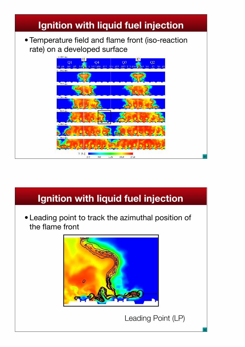
Ignition with liquid fuel injection• Temperature field and flame front (iso-reaction
rate) on a developed surface
52
Ignition with liquid fuel injection
• Leading point to track the azimuthal position of the flame front
Leading Point (LP)

53
54
• Leading point to track the azimuthal position of the flame front:
Ignition with liquid fuel injection

55
Azimuthal flame speed
Note: Sl=1 m/s
Flame is carried from burner to burner by:- the mean swirling motion- the turbulence- the dilatation of the burnt gases.
DILATATION: BACK TO BASICS
56
Ch. 2, Sec 2.7.3Balance equation for the total mass of burnt gas M:
The mass of burnt gas increases because of the burnt gas produced at the flame:
so that the flame front moves at:
M =4
3πr3ρ2
dr
dt=
ρ1ρ2
sl
dM
dt= 4πr2ρ1sL

Copyright Dr T. Poinsot 2013 57
The flame front moves faster than the flame speed by a factor of the order of 6 to 10 (density ratio). This is the
major contribution to acceleration in the gas turbine too.
dr
dt=
ρ1ρ2
sl Ch. 2, Sec 2.7.3
CONCLUSION
• IN AN ANNULAR CHAMBER, THE FLAME PROPAGATION IS DRIVEN BY DILATATION. CHANGING THE OUTLET SHAPE FOR EXAMPLE WILL CHANGE THE IGNITION SPEED
• HOWEVER, THE ‘DETAILS’ OF THE PROPAGATION REMAIN IMPORTANT
• NEED FOR NEW EXPERIMENTS: SEE EM2C EXAMPLE
58

IGNITION IN ANNULAR CHAMBERS
59The EM2C annular rig
Copyright Dr T. Poinsot 2013
IGNITION IN ANNULAR CHAMBERS
60
!"#$%&'"()*+,'"%-.%&'-&#$"%#$/%#)'%
01%23)'4%)$5"6+-'2%
%%%788%((%
%%988%((%
:-3"'%;%<8%=>%%%%%?(@)"$+%&'"22,'"%

OUTLINE
• IGNITION OF A METHANE JET IN AIR: WHERE SHOULD THE SPARK BE ?
• IGNITION IN GAS TURBINE CHAMBERS: PROPAGATION OF THE FLAME FROM BURNER TO BURNER
• IGNITION IN ROCKET ENGINES: VIOLENT EVENTS
• IGNITION IN BUILDINGS: COMPUTING THE OVER PRESSURE
• SPARK MODELING: THE DIFFICULT PART
61
ROCKET IGNITION
6254
Test rig M3[1] operated at DLR (Germany) :
[1] V. Schmidt, U. Wepler, O. Haidn and M. Oschwald, CharacterizaAon of the Primary IgniAon Process of a Coaxial GH2/LOX Spray, AIAA-‐2004-‐1167, 42nd AIAA Aerospace Sciences MeeAng and Exhibit, Reno, Nevada, 2004.
Coaxial injector
Exhaust nozzle
Aim of experiment: study of igni$on and flame propaga$on in a rocket-‐like configuraLon by opLcal diagnosLcs (OH* emission and Schlieren).
63
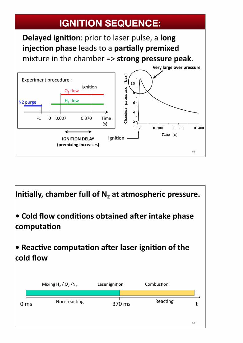
Delayed igni:on: prior to laser pulse, a long injec:on phase leads to a par:ally premixed mixture in the chamber => strong pressure peak.
Time (s)
N2 purge H2 flow
O2 flow
-‐1 0 0.007 0.370
Experiment procedure :Igni=on
IgniLon
Introduc*on ConclusionPart I Part II Part III Part IVIGNITION SEQUENCE:
Very large over pressure
IGNITION DELAY (premixing increases)
64
Ini:ally, chamber full of N2 at atmospheric pressure.
• Cold flow condi:ons obtained aFer intake phase computa:on
• Reac:ve computa:on aFer laser igni:on of the cold flow
t0 ms 370 ms
Mixing H2 / O2 /N2 Laser igni=on Combus=on
Non-‐reacLng ReacLng
Introduc*on ConclusionPart I Part II Part III Part IV

65
Nb of nodes : 796 000Nb of cells : 3 500 000H2 injecLon dome (used
because of back-‐flow)
Chamber
Atmosphere
Introduc*on ConclusionPart I Part II Part III Part IVLES MESH AND SETUP:
66
Black line : Vx = 0 m/s
Laser point
Introduc*on ConclusionPart I Part II Part III Part IVFLOW STATE AT IGNITION TIME

67
Black line : Vx = 0 m/s
Laser point
Introduc*on ConclusionPart I Part II Part III Part IV
68
Balck line : Vx=0 m/s
Laser point
(Φ)
Introduc*on ConclusionPart I Part II Part III Part IV

69
Balck line : Vx=0 m/s
Laser point
(Φ)
Introduc*on ConclusionPart I Part II Part III Part IV
70
Introduc*on ConclusionPart I Part II Part III Part IV
A significant part of combus:on takes place when the flame is close to the walls. General rule in confined vessels (piston engines for example)

71
• Mixture is correct before igni:on• Mass fluxes at inlets and outlet are well represented • Overall consump:on rate is correct
10
8
6
4
2 Cha
mbe
r pre
ssur
e [b
ar]
543210 Time after ignition [ms]
DLR experiment LES
Introduc*on ConclusionPart I Part II Part III Part IVCOMPARING EXPT AND LES: P traces
10 bars= danger
72
35 µs 250 µs 680 µs
LES
35 µs 250 µs 680 µsTime aMer igni=on:
Experiment (DLR)
Time aMer igni=on:
Schlieren images
Numerical Schlieren images
Introduc*on ConclusionPart I Part II Part III Part IVCOMPARING EXPT AND LES: Schlieren

OUTLINE
• IGNITION OF A METHANE JET IN AIR: WHERE SHOULD THE SPARK BE ?
• IGNITION IN GAS TURBINE CHAMBERS: PROPAGATION OF THE FLAME FROM BURNER TO BURNER
• IGNITION IN ROCKET ENGINES: VIOLENT EVENTS
• IGNITION IN BUILDINGS: COMPUTING THE OVER PRESSURE
• SPARK MODELING: THE DIFFICULT PART
73
IGNITION IN BUILDINGS• When there is a gas leak in a building (for example an offshore platform),
the consequences can be dramatic
• The overpressure which can be accepted for the building structure is not very large: designing buildings which do not lead to large overpressures and can survive explosions is a critical question
74

EXPLOSION ISSUES:
• AVOID LEAKS OF GAS...
• IF THERE IS A LEAK, ADD AN INHIBITOR (AN INERT GAS OR A POWDER) AND MIX IT WITH THE GAS/AIR MIXTURE FAST ENOUGH TO PREVENT ANY FLAME DEVELOPMENT -> DIFFICULT (THE INHIBITION PRODUCT SHOULD NOT KILL PEOPLE IN THE BUILDING)
• DESIGN BUILDINGS WHICH DO NOT LEAD TO LARGE OVERPRESSURES IN CASE OF EXPLOSIONS: «Venting chamber test cases»
75
76
Context: what is a ven*ng chamber?
Dorofeev, S.B. Proc. Combust. Inst. (2011)
Patel, S. et al. Proc. Combust. Inst. (2002)
Makarov, D. et al. Int. Journal Hydrogen Energy. (2010)
Kent, J. et al. 5th Asia-‐Pacific Conf. Combust. , Adelaide, Australia (2005)
⇒Applica=on : Safety aspects related to explosions in industrial buildings
77
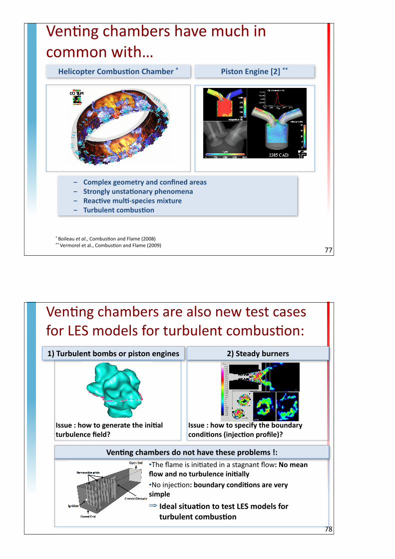
Ven*ng chambers have much in common with…
* Boileau et al., Combus*on and Flame (2008)** Vermorel et al., Combus*on and Flame (2009)
Helicopter Combus$on Chamber * Piston Engine [2] **
- Complex geometry and confined areas - Strongly unstaConary phenomena- ReacCve mulC-‐species mixture- Turbulent combusCon
78
Ven*ng chambers are also new test cases for LES models for turbulent combus*on:1) Turbulent bombs or piston engines
Ven$ng chambers do not have these problems !:
Issue : how to generate the iniCal turbulence field?
2) Steady burners
•The flame is ini=ated in a stagnant flow: No mean flow and no turbulence iniCally•No injec=on: boundary condiCons are very simple
⇒ Ideal situa$on to test LES models for turbulent combus$on
Issue : how to specify the boundary condiCons (injecCon profile)?

79
A.R. Masri et al., Industrial & Engineering Chemistry Research, 2012
A really good turbulent combus:on model should work at all scales without changing any parameter...
Ven*ng chambers allow a varia*on in scales which is unseen in other systems
Sydney Explosion Chamber [1]
• Box : – 0.05 x 0.05 x 0.25 m3 (small-‐scale)– 0.3 x 0.3 x 1.5 m3 (medium-‐scale)
• Fully filled with Fuel/Air mixture
• Fuels : C3H8 or CH4 or H2
• One central square obstrucLon
• 3 turbulence generaLng grids (removable)
• Laser igniLon at the closed end of the chamber in the iniLally quiet mixture
80[1] Masri, A.R. Al-‐Harbi, A. Meares, S. and Ibrahim, S .“A ComparaAve Study of Turbulent Premixed Flames PropagaAng Past Repeated Obstacles”, Industrial & Engineering Chemistry Research (2012)
0grid 2grids1grid 3grids
Different configura=ons studied:
Test-‐CaseGeometry
g3
g2
g1

Same setup - three sizes:
81
X 1
X 6
X 24
SCALE VOLUME
X 1
X 216
X 13824
Masri setupUniversity of Sydney
Scaled-‐up reproduc:on of Masri setup (x24) -‐ 6,1mExperiments by
GEXCON
Scaled-‐up reproduc:on of Masri
setup (x6) -‐ 1,5mExperiments by
GEXCON
82
Maximum overpressure
Test-‐CaseProblem DescripLon
Comparison with experimental data:
• Flame structure
• Flame posiLon
• Maximum overpressure
• Influence of adding/removing grids
Experimental images of flame propaga=on [2]:
[2] Gubba, S.R. et al., Combust. Sci. Tech. (2008).
Complex problem mixing:
• IgniLon
• Laminar phase propagaLon
• TransiLon to turbulence
• Turbulent propagaLon
• RelaminarisaLon8ms 10ms 11ms 12ms11,5ms

83
SPARK
ComputaLonal domain: The atmosphere is meshed
Meshes:
• Tetrahedra• Cell size in the chamber :
– small scale : 0.5mm– Medium scale : 3 cm
• Total cell number : 20 millions• CPU *me (BlueGene /P : Babel (Idris)):
– Small scale 100 000h– Medium scale 150 000h
84
Results – Small Scale ChamberFlame PropagaLon
• Long laminar phase controls the flame shape and speed before it touches the obstacles
• Fast acceleraLon when flame becomes turbulent• AcousLc oscillaLons at the end of combusLon

85
LES images of Config2 with AVBP:
Experimental images of Config2 [2]:
Results – Small Scale ChamberFlame Structure
Good agreement between LES and experiments:
• Laminar spherical flame
• “finger” flame
• InteracLon flame/obstacle
• Turbulent structures
• Flame acceleraLon
[2] Gubba, S.R. et al., Combust. Sci. Tech. (2008).
86
Overpressure [m
bar]
• Over-‐es=ma=on of the maximum overpressure reached by Charle\e’s model.
• Colin’s model gives the right behavior.
Colin [1] CharleSe [2]
Turbulent combus=on model for small scale chamber simula=ons: Colin
Time (ms) Time (ms)
Results – Small Scale ChamberChoice of the turbulent combusLon model
[1] Colin et al, Physics of fluids, 2000[2] Charlebe et al, CombusKon and Flame, 2002[3] Masri, et al, Industrial & Engineering Chemistry Research, 2012
g3
g2
g1
[3]

87
➞ Good esCmaCon of overpressure magnitude➞ Post-‐maximum pressure oscillaCons accurately
captured
➞ Grids influence on overpressure correctly predicted by LES
Results – Small Scale ChamberInfluence of the number of grids :
[1] Masri, et al, Industrial & Engineering Chemistry Research, 2012
— : Experiments mean [1] : Experiments envelope -‐ -‐ : LES -‐ Colin
1 grid
2 grids
3 grids
Results – Small Scale ChamberInfluence of the fuel type : Response to flame properLes Sl0, dl0
88
⇒ Fuel influence on overpressure correctly predicted by LES• CH4 generates a lower overpressure than C3H8
• H2 generates a much higher overpressure than C3H8 and CH4
⇒ May mainly be related to:• Laminar flame speeds : Sl0 (CH4) < Sl0 (C3H8) << Sl0 (H2)
[1] Masri, et al, Industrial & Engineering Chemistry Research, 2012
— : Experiments mean [1] : Experiments envelope -‐ -‐ : LES -‐ Colin
CH4
C3H8
H2

89
Masri setup25cm
Scaled-‐up reproduc*on of Masri setup (x6)1,5m
x6
Scaling things up: by 6
90
Results – Medium Scale ChamberFlame PropagaLon
LES
Experiments

91
Overpressure [m
bar]
Now:• Under-‐esCmaCon of the maximum overpressure reached by Colin’s model.• CharleSe’s model gives the right behavior.
Colin [1] CharleSe [2]
Turbulent combus:on model for medium scale chamber simula:ons: CharleZe?
Time (ms) Time (ms)
[1] Colin et al, Physics of fluids, 2000[2] CharleSe et al, CombusCon and Flame, 2002
g3
g2
g1
Results – Medium Scale ChamberChoice of the turbulent combus:on model
ImplicaLons for turbulent combusLon models
• In most engines, no change of scale comparable to the present one has ever been performed.
• Going from a volume of 1 to a volume of 24^3= 13000 shows that a given model with fixed coefficients has problems to work for all cases
• Dynamic formulation where coefficients change dynamically developed now (Wang et al Comb. Flame 2013)
92

THE OTHER PATH: ADD POINTS !
93
• Grid refinement can replace models !
• Adding more points when the scale increases is a simple but expensive way of solving the problem
• This requires very large computers. Example: the INCITE BG machines
1 billion cell LES:
94

OUTLINE
• IGNITION OF A METHANE JET IN AIR: WHERE SHOULD THE SPARK BE ?
• IGNITION IN GAS TURBINE CHAMBERS: PROPAGATION OF THE FLAME FROM BURNER TO BURNER
• IGNITION IN ROCKET ENGINES: VIOLENT EVENTS
• IGNITION IN BUILDINGS: COMPUTING THE OVER PRESSURE
• SPARK MODELING: THE DIFFICULT PART
95
Copyright Dr T. Poinsot 2013
THE HIDDEN PROBLEM OF ALL SIMULATIONS OF IGNITION
• MODELING THE INITIAL INSTANTS OF THE INTERACTION BETWEEN A SPARK (OR A LASER) AND THE FLOW IS THE MOST DIFFICULT PART
• TODAY THE MODELS REQUIRED FOR THIS PHASE OF THE IGNITION PROCESS ARE STILL UNCLEAR. IN 3D CODES, TWO USUAL MODELS:
➡ IGNITION = DEPOSITION OF ENERGY IN A SPHERE
➡ IGNITION PHASE IS FORGOTTEN AND REPLACED BY A KERNEL OF BURNT GASES OF MORE OR LESS ARBITRARY SHAPE AND TEMPERATURE
96

SPARK IGNITION: NEED TO TALK ABOUT ELECTRICAL CIRCUIT
97
98
The Energy deposiLon model (ED)
Spark = addiLonal term in the energy transport equaLon:
εi : total amount of energy transferred to the gas [J]
σr : characterisLc size of the deposiLon [m]
σt : duraLon [s]
Introduc*on ConclusionPart I Part II Part III Part IV

1D IGNITION (Lacaze PhD 2009):
99
SOME IGNITION ISSUES AND MODELS:
• MINIMUM IGNITION ENERGY (CHAMPION et al CF 1986, KELLEY et al CF2009)
• DO WE NEED TO MODEL THE PLASMA PHASE ?
• DO WE NEED TO MODEL THE ELECTRICAL CIRCUIT ?
• HOW MUCH ENERGY IS LOST TO THE ELECTRODES: A LOT !
• HOW MUCH DOES THE SPARK MOVE ? (COUPLING WITH THE FLOW): WHAT HAPPENS IF THERE IS A STRONG FLOW AT THE SPARK ?
• CAN THE SPARK CREATE MORE THAN ONE DISCHARGE ?
100

MINIMUM IGNITION ENERGY:
101
Temp!
Abscisse!T1!
T2!Tc!
2 !!• THE SPARK MUST CREATE A SPHERE OF BURNT GAS :
➡ LARGER THAN TWO FLAME THICKNESSES TO AVOID DIFFUSION TO KILL THE FLAME RIGHT AWAY
➡ WARMER THAN THE IGNITION TEMPERATURE WHICH IS CLOSE TO THE ADIABATIC FLAME TEMPERATURE
MINIMUM IGNITION ENERGY:
102
Temp!
Abscisse!T1!
Tc!
D>2 !!
Energie nécessaire!
E= 4/3 " !3 # Cp (T2-T1)!Application numérique à 1 bar et 300 K pour CH4/air:!!=0.5 mm!Cp=1200 J/kgK!T2-T1=2000 K!#=1.2 kg/m3$
E= 1 mJ !
Ignition energy
If P= 1 bar and T1=300 K for CH4/air:δ=0.5 mmCp=1200 J/kgKT2-T1=2000 Kρ=1.2 kg/m3E = 1 mJ

MEASUREMENTS OF MIE (CH4/AIR):
103
PHUOC, T., AND WHITE, F. Laser induced spark ignition of ch4/air mixtures. Combustion andFlame119 (1999), 203–216.
104
Electrical spark
Shock wave losses Radiative losses Conduction losses
(electrodes)
Energy deposited in the gas
Maly and Vogel 1978
- ≈ 5% of Etot ≈ 65% of Etot ≈ 30% of Etot
Teets and Sell 1989
≈ 70% of Etot ≈ 5% of Etot ≈ 15% of Etot ≈ 10% of Etot
Laser spark
Shock wave losses
Radiative losses Energy deposited in the gas
Phuoc and White 2002
60-70% of Etot ≈ 10-20% of Etot ≈ 10% of Etot
Introduc*on ConclusionPart I Part II Part III Part IVHow much energy Etot needed in the electrical circuit to have 1 mJ in the gas ? This depends on the losses and they are large:

IN PRACTICE:• MOST SPARKS WILL DEPOSIT MUCH MORE THAN 1 mJ
• NOT A PROBLEM EXCEPT IF YOU WANT TO BUILD A PREDICTIVE MODEL... BECAUSE THE SPARK ENERGY CONTROLS THE FLAME GROWTH LONG AFTER IGNITION:
• KELLEY ET AL
105
ENERGY DEPOSITION
• ED MODEL USED IN MULTIPLE SIMULATIONS: ASSUME SLOW (O(ms)) DEPOSITION OF ENERGY UNTIL FLAME STARTS. TEMPERATURE REMAINS SMALL (LESS THAN 5000 K). FLAME STARTS WHEN TEMPERATURE IS LARGE ENOUGH
• DO WE AGREE ON THE IGNITION PROCESS ITSELF ? THERE ARE OTHER VIEWS: THE ENERGY DEPOSITION IS SO SHORT THAT COMBUSTION IS FROZEN. TEMPERATURE GOES UP TO 10000K, A SHOCK WAVE IS FORMED. COMBUSTION STARTS ONLY LATER...
106Lee et al. 1969
Shock wave

IGNITION SCENARII: Energy deposition
107
Time
Total energy deposited from spark to gas Maximum temperature
Reaction rate
2500 K
Copyright Dr T. Poinsot 2013
IGNITION SCENARII: Shock
108Time
Total energy deposited from spark to gas
Maximum temperature
Reaction rate
2500 K


