Iglu'® - Disposable formwork for ventilated under-floor cavities
24
www.daliform.com Disposable formwork for ventilated under-floor cavities
-
Upload
daliform-group -
Category
Documents
-
view
41 -
download
0
description
Iglu'® (igloo) is a market leading product that was created and patented for the realisation of sanitary spaces, ventilated cavities, under-floor cavities, ventilated floors and roofs during the construction and restructuring of civil and industrial buildings. This result of an ingenious idea dating back to 1993 considerably improved building methods. The innovative capacity of Iglu'® has received numerous successes and recognitions on a national and international level, quickly confirming it as a product of excellence in the building world.The modular, plastic Iglu'® formworks, placed side by side in sequence according to a predefined direction, make it easy to quickly create a self-supporting pedestrian platform above which a layer of is cast in order to easily and economically create a ventilated slab placed on pillars with the below cavity area available for the passage of systems but above all ventilated to counteract rising humidity and radioactive gases.
Transcript of Iglu'® - Disposable formwork for ventilated under-floor cavities
www.daliform.com
Disposable formwork for ventilated under-fl oor cavities
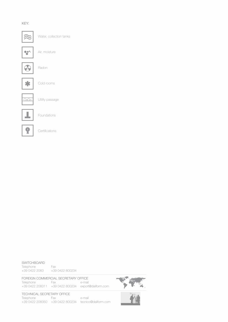
Water, collection tanks
Air, moisture
Radon
Cold rooms
Utility passage
Foundations
Certifi cations
KEY:
SWITCHBOARDTelephone Fax +39 0422 2083 +39 0422 800234
FOREIGN COMMERCIAL SECRETARY OFFICETelephone Fax e-mail+39 0422 208311 +39 0422 800234 [email protected]
TECHNICAL SECRETARY OFFICETelephone Fax e-mail+39 0422 208350 +39 0422 800234 [email protected]
3
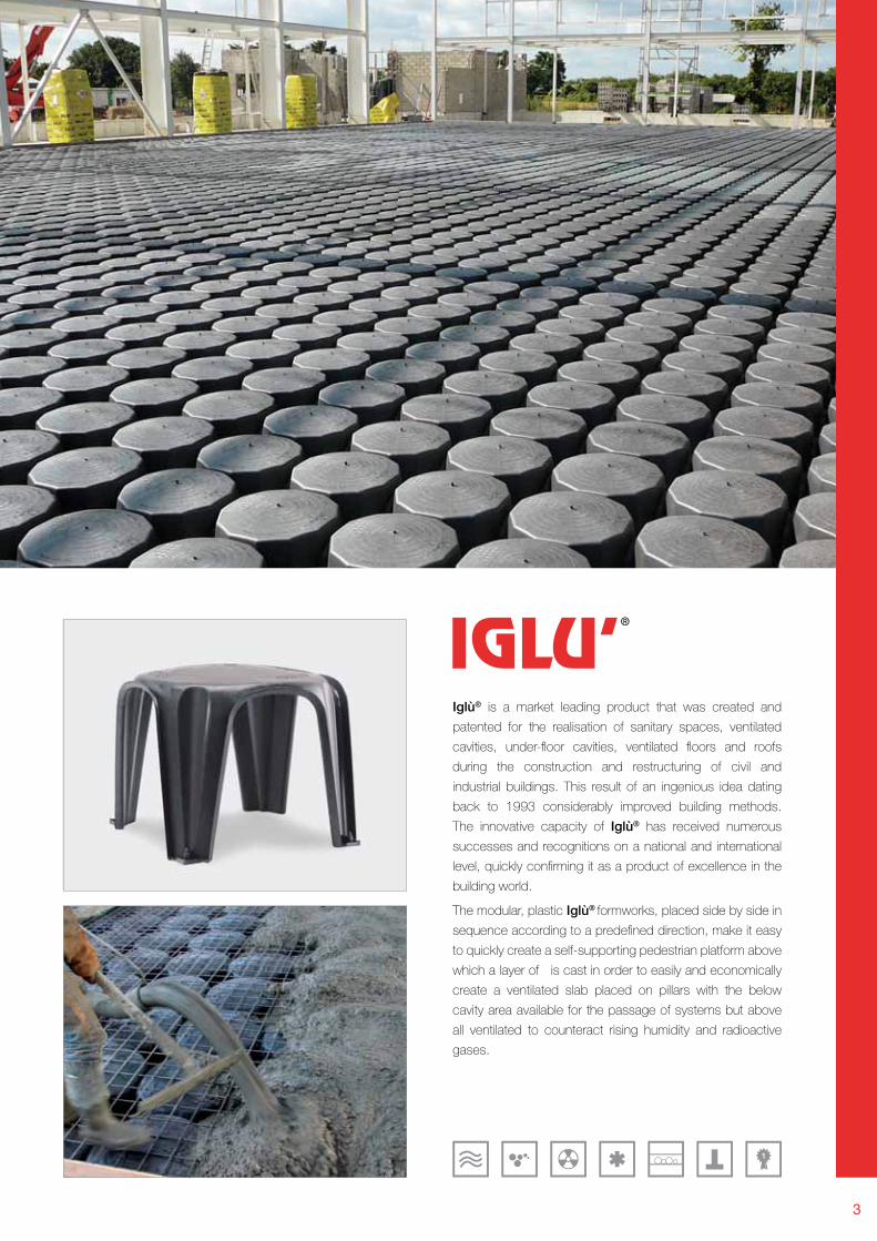
Iglù® is a market leading product that was created and
patented for the realisation of sanitary spaces, ventilated
cavities, under-fl oor cavities, ventilated fl oors and roofs
during the construction and restructuring of civil and
industrial buildings. This result of an ingenious idea dating
back to 1993 considerably improved building methods.
The innovative capacity of Iglù® has received numerous
successes and recognitions on a national and international
level, quickly confi rming it as a product of excellence in the
building world.
The modular, plastic Iglù® formworks, placed side by side in
sequence according to a predefi ned direction, make it easy
to quickly create a self-supporting pedestrian platform above
which a layer of is cast in order to easily and economically
create a ventilated slab placed on pillars with the below
cavity area available for the passage of systems but above
all ventilated to counteract rising humidity and radioactive
gases.
4
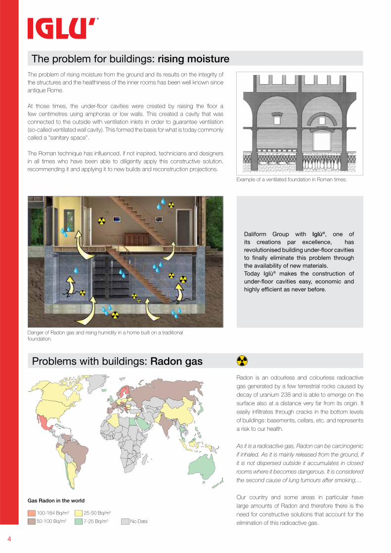
Problems with buildings: Radon gas
The problem of rising moisture from the ground and its results on the integrity of
the structures and the healthiness of the inner rooms has been well known since
antique Rome.
At those times, the under-fl oor cavities were created by raising the fl oor a
few centimetres using amphoras or low walls. This created a cavity that was
connected to the outside with ventilation inlets in order to guarantee ventilation
(so-called ventilated wall cavity). This formed the basis for what is today commonly
called a "sanitary space".
The Roman technique has infl uenced, if not inspired, technicians and designers
in all times who have been able to diligently apply this constructive solution,
recommending it and applying it to new builds and reconstruction projections.
Daliform Group with Iglù®, one of
its creations par excellence, has
revolutionised building under-floor cavities
to finally eliminate this problem through
the availability of new materials.
Today Iglù® makes the construction of
under-floor cavities easy, economic and
highly efficient as never before.
Radon is an odourless and colourless radioactive
gas generated by a few terrestrial rocks caused by
decay of uranium 238 and is able to emerge on the
surface also at a distance very far from its origin. It
easily infi ltrates through cracks in the bottom levels
of buildings: basements, cellars, etc. and represents
a risk to our health.
As it is a radioactive gas, Radon can be carcinogenic
if inhaled. As it is mainly released from the ground, if
it is not dispersed outside it accumulates in closed
rooms where it becomes dangerous. It is considered
the second cause of lung tumours after smoking....
Our country and some areas in particular have
large amounts of Radon and therefore there is the
need for constructive solutions that account for the
elimination of this radioactive gas.
Danger of Radon gas and rising humidity in a home built on a traditional foundation.
Example of a ventilated foundation in Roman times.
The problem for buildings: rising moisture
100-184 Bq/m3
50-100 Bq/m3
25-50 Bq/m3
7-25 Bq/m3 No Data
Gas Radon in the world
5
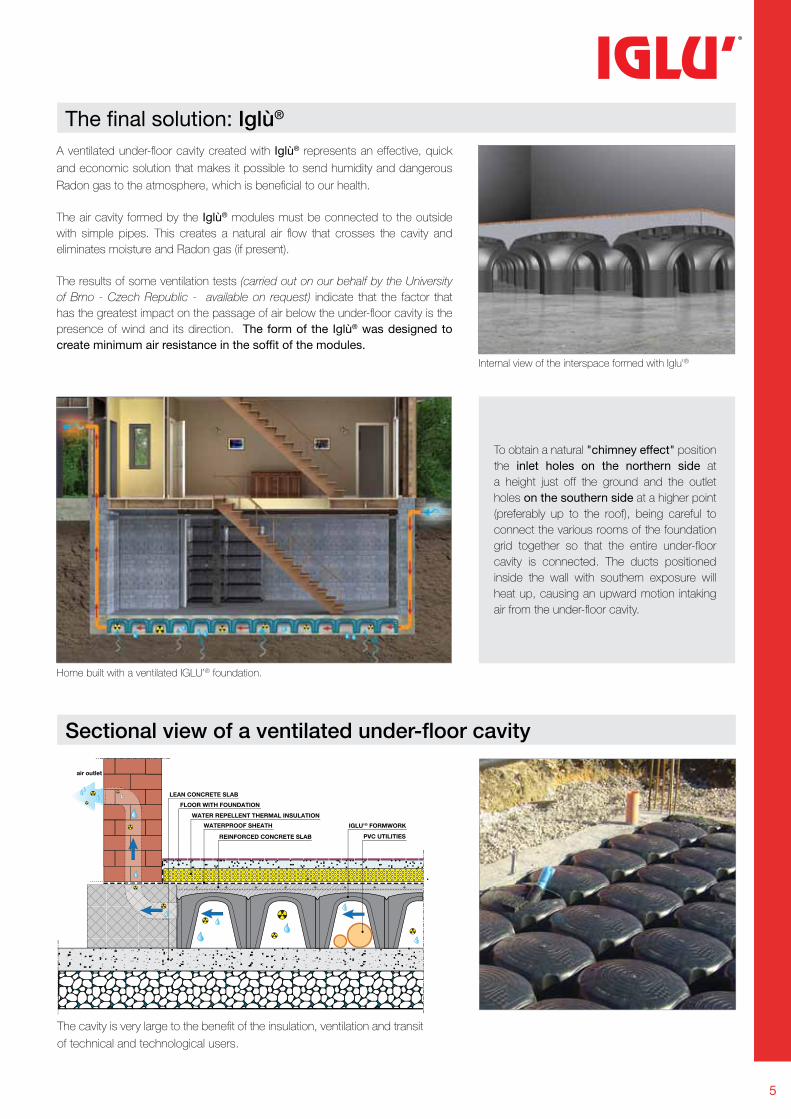
Sectional view of a ventilated under-fl oor cavity
Home built with a ventilated IGLU’® foundation.
Internal view of the interspace formed with Iglu'®
The final solution: Iglù®
A ventilated under-fl oor cavity created with Iglù® represents an effective, quick
and economic solution that makes it possible to send humidity and dangerous
Radon gas to the atmosphere, which is benefi cial to our health.
The air cavity formed by the Iglù® modules must be connected to the outside
with simple pipes. This creates a natural air fl ow that crosses the cavity and
eliminates moisture and Radon gas (if present).
The results of some ventilation tests (carried out on our behalf by the University
of Brno - Czech Republic - available on request) indicate that the factor that
has the greatest impact on the passage of air below the under-fl oor cavity is the
presence of wind and its direction. The form of the Iglù® was designed to
create minimum air resistance in the soffit of the modules.
The cavity is very large to the benefi t of the insulation, ventilation and transit
of technical and technological users.
WATERPROOF SHEATH
LEAN CONCRETE SLAB
FLOOR WITH FOUNDATION
WATER REPELLENT THERMAL INSULATION
REINFORCED CONCRETE SLAB
IGLU’® FORMWORK
air outlet
PVC UTILITIES
To obtain a natural "chimney effect" position
the inlet holes on the northern side at
a height just off the ground and the outlet
holes on the southern side at a higher point
(preferably up to the roof), being careful to
connect the various rooms of the foundation
grid together so that the entire under-fl oor
cavity is connected. The ducts positioned
inside the wall with southern exposure will
heat up, causing an upward motion intaking
air from the under-fl oor cavity.
6
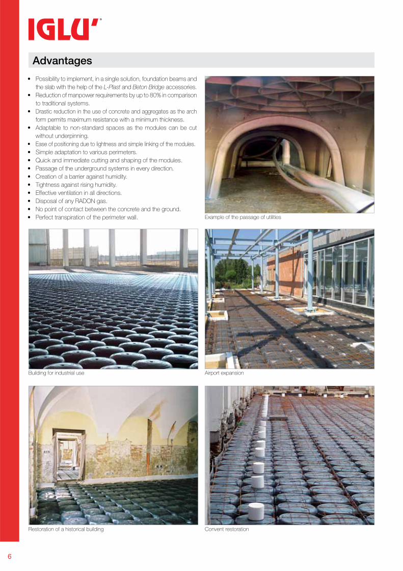
Advantages
Airport expansion
Convent restoration
Building for industrial use
Restoration of a historical building
Example of the passage of utilities
• Possibility to implement, in a single solution, foundation beams and
the slab with the help of the L-Plast and Beton Bridge accessories.
• Reduction of manpower requirements by up to 80% in comparison
to traditional systems.
• Drastic reduction in the use of concrete and aggregates as the arch
form permits maximum resistance with a minimum thickness.
• Adaptable to non-standard spaces as the modules can be cut
without underpinning.
• Ease of positioning due to lightness and simple linking of the modules.
• Simple adaptation to various perimeters.
• Quick and immediate cutting and shaping of the modules.
• Passage of the underground systems in every direction.
• Creation of a barrier against humidity.
• Tightness against rising humidity.
• Effective ventilation in all directions.
• Disposal of any RADON gas.
• No point of contact between the concrete and the ground.
• Perfect transpiration of the perimeter wall.
7
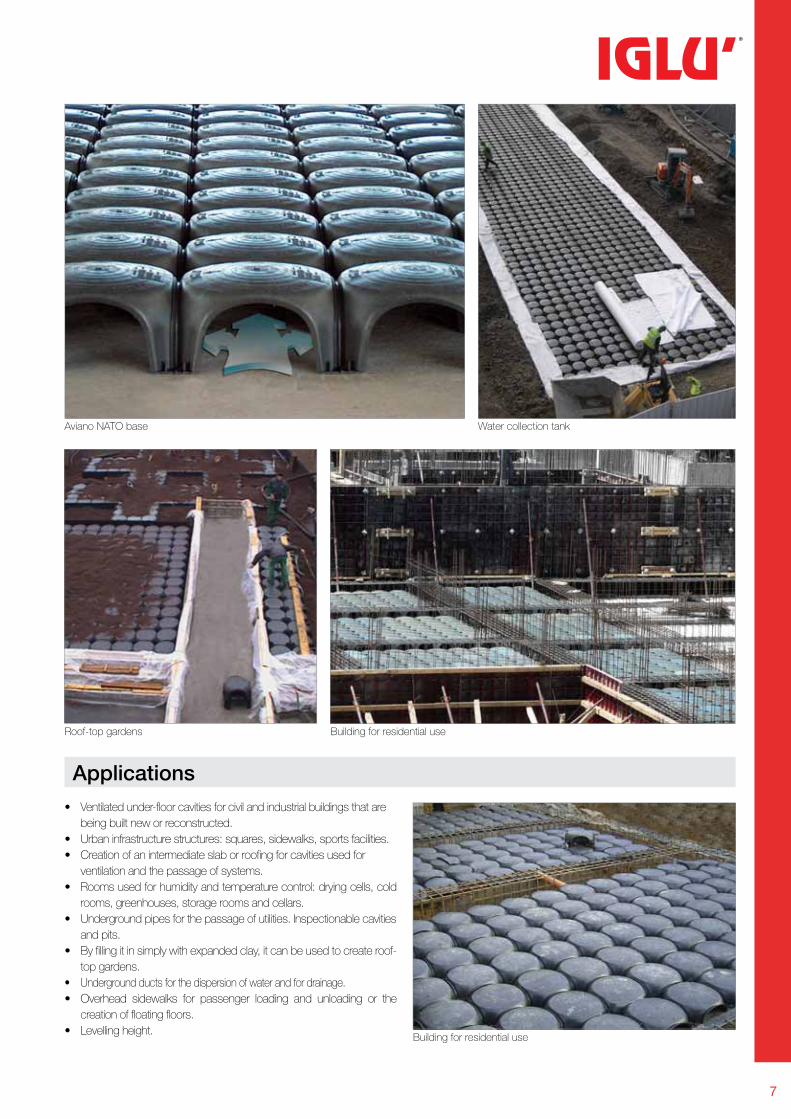
• Ventilated under-fl oor cavities for civil and industrial buildings that are
being built new or reconstructed.
• Urban infrastructure structures: squares, sidewalks, sports facilities.
• Creation of an intermediate slab or roofi ng for cavities used for
ventilation and the passage of systems.
• Rooms used for humidity and temperature control: drying cells, cold
rooms, greenhouses, storage rooms and cellars.
• Underground pipes for the passage of utilities. Inspectionable cavities
and pits.
• By fi lling it in simply with expanded clay, it can be used to create roof-
top gardens.
• Underground ducts for the dispersion of water and for drainage.
• Overhead sidewalks for passenger loading and unloading or the
creation of fl oating fl oors.
• Levelling height.
Applications
Aviano NATO base
Roof-top gardens Building for residential use
Building for residential use
Water collection tank
50x50
5,8
5,8
5,5
0,013
1,200
110x110x220
576
480
120
8
205
11
1210 161412 20181650x50
8
8
8
0,016
1,250
110x110x225
530
400
100
12
205
8
50x50
7,7
7,7
7,5
0,021
1,225
110x110x220
576
480
120
10
205
9
50x50
11
11
9,5
0,034
1,300
110x110x244
420
300
75
14
205
7
50x50
13
13
10
0,035
1,450
110x110x236
465
300
75
18
205
7
50x50
9,8
9,8
9,4
0,028
1,250
110x110x230
420
340
85
12
205
7
50x50
11,8
11,8
11
0,030
1,275
110x110x220
420
320
80
14
205
11
50x50
13,8
13,8
12,5
0,033
1,300
110x110x220
430
320
80
16
205
9
109
850x50
5,9
5,9
5,9
0,010
0,875
110x110x256
640
600
150
6
205
13
650x50
3,9
3,9
3,9
0,007
0,840
110x110x254
520
600
150
3
205
15
850x50
4,5
4,5
4,5
0,012
1,240
110x110x210
525
400
100
8
205
12
450x50
3
3
3
0,004
0,770
110x110x110
310
400
100
50x50
2,2
2,2
2,2
0,006
0,800
110x110x252
500
600
150
4
50 (57,8) (71)
A
B B
h
50
hA
B B
50
50
ab
h
Iglù®
H 4Iglù®+H 4
Iglù®+H 6
Iglù®
H 8Iglù®+H 8
Iglù®+H 10
Iglù®
H 12Iglù®+H 12
Iglù®+H 14
Iglù®
H 16Iglù®+H 16
400 4 Ø 5/25x25
0
5
10
1,65
0,19
0,08
1,16
0,26
0,126
1,31
0,275
0,13
0,78
0,31
0,18
1,57
0,29
0,136
0,151
0,30
0,138
0,94
0,34
0,19
1,92
0,33
0,15
0,93
0,34
0,19
0,94
0,35
0,20
0,98
0,36
0,2
600 4 Ø 5/25x25
0
5
10
2,29
0,25
0,10
1,63
0,34
0,16
1,83
0,36
0,165
1,08
0,40
0,22
2,12
0,39
0,17
2,08
0,39
0,17
1,28
0,45
0,24
2,61
0,43
0,185
1,25
0,44
0,24
1,26
0,45
0,25
1,32
0,46
0,25
1100 5 Ø 6/20x20
0
5
10
3,98
0,41
0,15
2,84
0,56
0,247
3,2
0,59
0,255
1,86
0,65
0,35
3,8
0,63
0,267
3,57
0,62
0,26
2,20
0,72
0,37
4,4
0,68
0,28
2,11
0,7
0,37
2,10
0,71
0,37
2,21
0,73
0,37
2100 6 Ø 6/20x20
0
5
10
7,29
0,72
0,26
5,2
0,98
0,418
5,87
1,03
0,43
3,37
1,14
0,58
7,04
1,16
0,45
6,48
1,08
0,44
3,98
1,25
0,62
7,99
1,18
0,47
3,8
1,22
0,61
3,74
1,22
0,61
3,95
1,25
0,62
1.000
0
5
10
2,90
0,39
0,15
3 Ø5 25 x 25
3.000
0
5
10
8,00
0,98
0,36
4 Ø5 20 x 20
5.000
5
10
15
1,60
0,57
0,29
5 Ø6 20 x 20
10.000
5
10
15
3,10
1,10
0,56
6 Ø8 20 x 20
20.000
10
15
20
2,10
1,10
0,66
10 Ø8 15 x 15
50 (57,8) (71)
50 (5
7,8)
(71)
DALIFORMGROUP
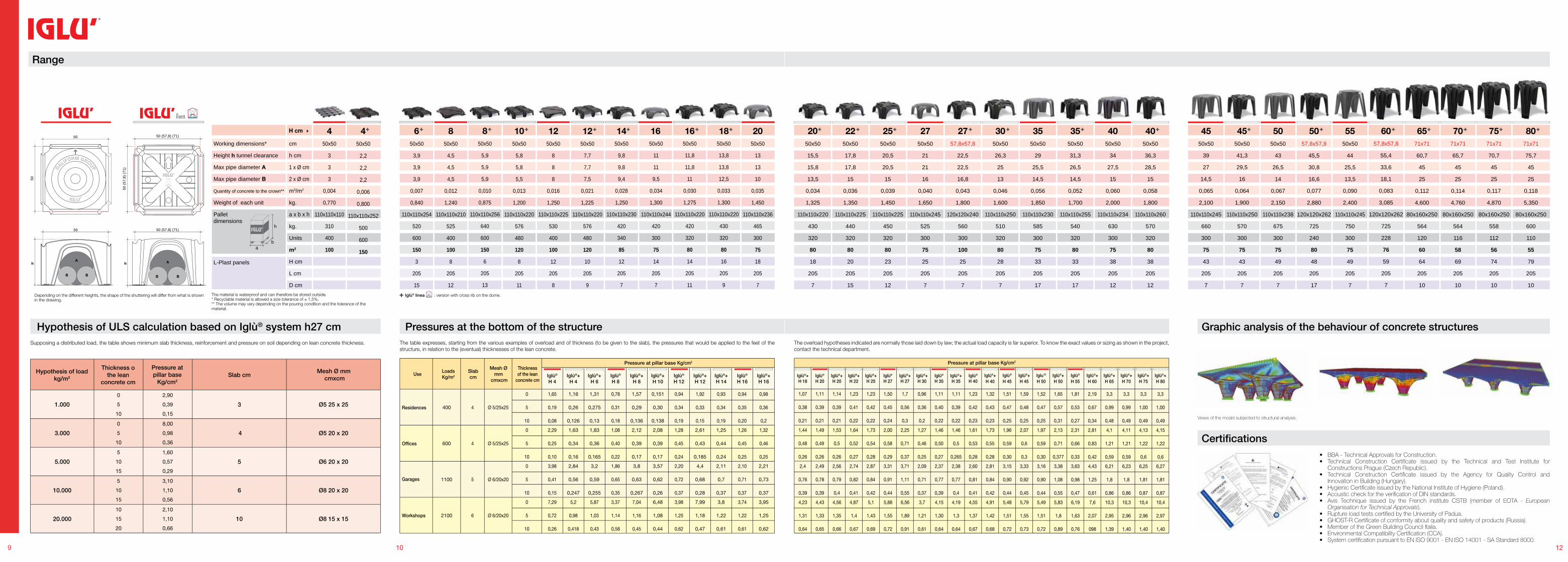
Pressures at the bottom of the structure
The table expresses, starting from the various examples of overload and of thickness (to be given to the slab), the pressures that would be applied to the feet of the structure, in relation to the (eventual) thicknesses of the lean concrete.
Range
The material is waterproof and can therefore be stored outside.* Recyclable material is allowed a size tolerance of ± 1,5%.** The volume may vary depending on the pouring condition and the tolerance of the material.
Iglù® linea : version with cross rib on the dome.Depending on the different heights, the shape of the shuttering will differ from what is shown in the drawing.
cm
h cm
1 x Ø cm
2 x Ø cm
m3/m2
kg.
a x b x hkg.
Units
m2
H cm
L cm
D cm
Working dimensions*
Height h tunnel clearance
Max pipe diameter A
Max pipe diameter B
Quantity of concrete to the crown**
Weight of each unit
Palletdimensions
L-Plast panels
H cm
Use
Residences
Offi ces
Garages
Workshops
LoadsKg/m2
Slabcm
Mesh Ø mm
cmxcm
Thickness of the lean
concrete cm
Pressure at pillar base Kg/cm2
Hypothesis of ULS calculation based on Iglù® system h27 cm
Hypothesis of load kg/m2
Slab cmMesh Ø mm
cmxcm
Thickness othe lean
concrete cm
Pressure atpillar base
Kg/cm2
Supposing a distributed load, the table shows minimum slab thickness, reinforcement and pressure on soil depending on lean concrete thickness.
272522 27 35 3530 40 40 45 45 50 5550 7570656050x50
21
21
16
0,040
1,650
110x110x245
525
300
75
25
205
7
50x50
29
25,5
14,5
0,056
1,850
110x110x230
585
300
75
33
205
17
50x50
34
27,5
15
0,060
2,000
110x110x234
630
300
75
38
205
12
50x50
39
27
14,5
0,065
2,100
110x110x245
660
300
75
43
205
7
50x50
43
26,5
14
0,067
2,150
110x110x238
675
300
75
49
205
7
50x50
44
25,5
13,5
0,090
2,400
110x110x245
750
300
75
49
205
7
50x50
17,8
17,8
15
0,036
1,350
110x110x225
440
320
80
20
205
15
50x50
20,5
20,5
15
0,039
1,450
110x110x225
450
320
80
23
205
12
57,8x57,8
22,5
22,5
16,8
0,043
1,800
120x120x240
560
300
100
25
205
7
50x50
26,3
25
13
0,046
1,600
110x110x250
510
320
80
28
205
7
50x50
31,3
26,5
14,5
0,052
1,700
110x110x255
540
320
80
33
205
17
50x50
36,3
28,5
15
0,058
1,800
110x110x260
570
320
80
38
205
12
57,8x57,8
45,5
30,8
16,6
0,077
2,880
120x120x262
725
240
80
48
205
17
57,8x57,8
55,4
33,6
18,1
0,083
3,085
120x120x262
725
228
76
59
205
7
50x50
41,3
29,5
16
0,064
1,900
110x110x250
570
300
75
43
205
7
71x71
60,7
45
25
0,112
4,600
80x160x250
564
120
60
64
205
10
71x71
65,7
45
25
0,114
4,760
80x160x250
564
116
58
69
205
10
71x71
70,7
45
25
0,117
4,870
80x160x250
558
112
56
74
205
10
12
8071x71
75,7
45
25
0,118
5,350
80x160x250
600
110
55
79
205
10
2050x50
15,5
15,8
13,5
0,034
1,325
110x110x220
430
320
80
18
205
7
Iglù®+H 18
Iglù®
H 20Iglù®+H 20
Iglù®+H 22
Iglù®+H 25
Iglù®
H 27Iglù®+H 27
Iglù®+H 30
Iglù®
H 35Iglù®+H 35
Iglù®
H 40
Iglù®+H 40
Iglù®
H 45
Iglù®+H 45
Iglu’®
H 50
Iglù®+H 50
Iglù®
H 55
Iglù®+H 60
Iglù®+H 65
Iglù®+H 70
Iglù®+H 75
Iglù®+H 80
1,07
0,38
0,21
1,11
0,39
0,21
1,14
0,39
0,21
1,23
0,41
0,22
1,23
0,42
0,22
1,50
0,45
0,24
1,7
0,56
0,3
0,96
0,36
0,2
1,11
0,40
0,22
1,11
0,39
0,22
1,23
0,42
0,23
1,32
0,43
0,23
1,51
0,47
0,25
1,59
0,48
0,25
1,52
0,47
0,25
1,65
0,57
0,31
1,81
0,53
0,27
2,19
0,67
0,34
3,3
0,99
0,48
3,3
0,99
0,49
3,3
1,00
0,49
3,3
1,00
0,49
1,44
0,48
0,26
1,49
0,49
0,26
1,53
0,5
0,26
1,64
0,52
0,27
1,73
0,54
0,28
2,00
0,58
0,29
2,25
0,71
0,37
1,27
0,46
0,25
1,46
0,50
0,27
1,46
0,5
0,265
1,61
0,53
0,28
1,73
0,55
0,28
1,96
0,59
0,30
2,07
0,6
0,3
1,97
0,59
0,30
2,13
0,71
0,377
2,31
0,66
0,33
2,81
0,83
0,42
4,1
1,21
0,59
4,11
1,21
0,59
4,13
1,22
0,6
4,15
1,22
0,6
2,4
0,76
0,39
2,49
0,78
0,39
2,56
0,79
0,4
2,74
0,82
0,41
2,87
0,84
0,42
3,31
0,91
0,44
3,71
1,11
0,55
2,09
0,71
0,37
2,37
0,77
0,39
2,38
0,77
0,4
2,60
0,81
0,41
2,81
0,84
0,42
3,15
0,90
0,44
3,33
0,92
0,45
3,16
0,90
0,44
3,38
1,08
0,55
3,63
0,98
0,47
4,43
1,25
0,61
6,21
1,8
0,86
6,23
1,8
0,86
6,25
1,81
0,87
6,27
1,81
0,87
4,23
1,31
0,64
4,43
1,33
0,65
4,56
1,35
0,66
4,87
1,4
0,67
5,1
1,43
0,69
5,88
1,55
0,72
6,56
1,89
0,91
3,7
1,21
0,61
4,15
1,30
0,64
4,19
1,3
0,64
4,55
1,37
0,67
4,91
1,42
0,68
5,48
1,51
0,72
5,79
1,55
0,73
5,49
1,51
0,72
5,83
1,8
0,89
6,19
1,63
0,76
7,6
2,07
098
10,3
2,95
1,39
10,3
2,96
1,40
10,4
2,96
1,40
10,4
2,97
1,40
• BBA - Technical Approvals for Construction.• Technical Construction Certifi cate issued by the Technical and Test Institute for Constructions Prague (Czech Republic).• Technical Construction Certifi cate issued by the Agency for Quality Control and Innovation in Building (Hungary).• Hygienic Certifi cate issued by the National Institute of Hygiene (Poland).• Acoustic check for the verifi cation of DIN standards.• Avis Technique issued by the French institute CSTB (member of EOTA - European Organisation for Technical Approvals). • Rupture load tests certifi ed by the University of Padua.• GHOST-R Certifi cate of conformity about quality and safety of products (Russia).• Member of the Green Building Council Italia.• Environmental Compatibility Certifi cation (CCA).• System certifi cation pursuant to EN ISO 9001 - EN ISO 14001 - SA Standard 8000.
Certifi cations
Graphic analysis of the behaviour of concrete structures
Views of the model subjected to structural analysis.
Pressure at pillar base Kg/cm2
The overload hypotheses indicated are normally those laid down by law; the actual load capacity is far superior. To know the exact values or sizing as shown in the project, contact the technical department.
14
1
5
4
6
2
3
1 2
1
3
2
5
6
4
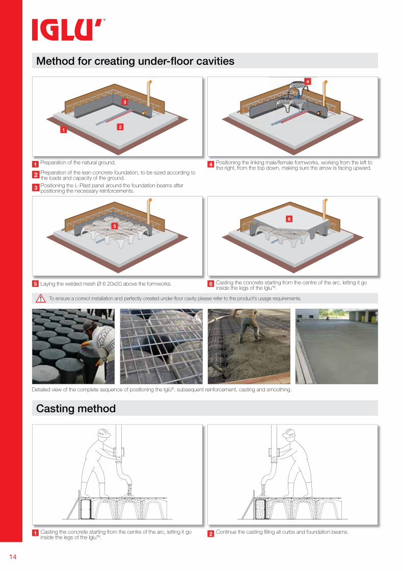
Method for creating under-fl oor cavities
Preparation of the natural ground.
Laying the welded mesh Ø 6 20x20 above the formworks.
Positioning the linking male/female formworks, working from the left to the right, from the top down, making sure the arrow is facing upward.
Casting the concrete starting from the centre of the arc, letting it go inside the legs of the Iglu’®.
Preparation of the lean concrete foundation, to be sized according to the loads and capacity of the ground.
Positioning the L-Plast panel around the foundation beams after positioning the necessary reinforcements.
Casting the concrete starting from the centre of the arc, letting it go inside the legs of the Iglu’®.
Continue the casting fi lling all curbs and foundation beams.
Detailed view of the complete sequence of positioning the Iglù®, subsequent reinforcement, casting and smoothing.
Casting method
To ensure a correct installation and perfectly created under-fl oor cavity please refer to the product’s usage requirements.
15
1
2
3
A2 A3 A4A1
B1
C1 C2 C3 C4 C5
B2 B3 B4 B5
A5
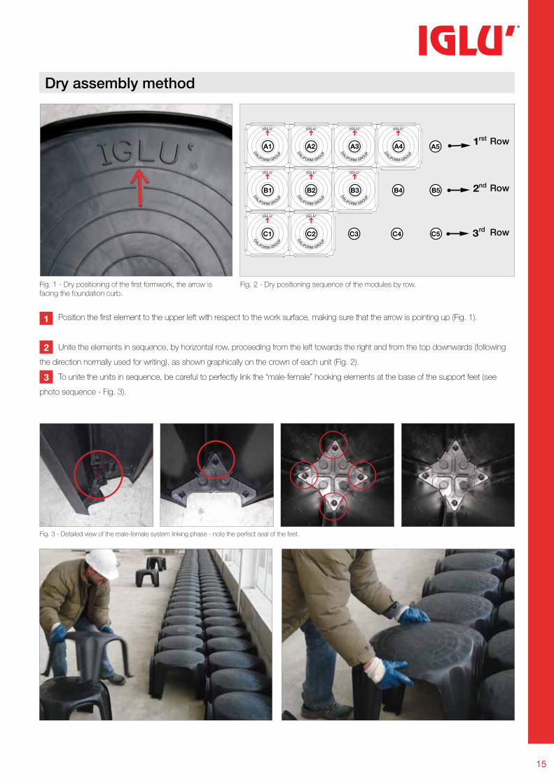
Dry assembly method
Fig. 1 - Dry positioning of the fi rst formwork, the arrow is facing the foundation curb.
Fig. 2 - Dry positioning sequence of the modules by row.
Fig. 3 - Detailed view of the male-female system linking phase - note the perfect seal of the feet.
Position the fi rst element to the upper left with respect to the work surface, making sure that the arrow is pointing up (Fig. 1).
Unite the elements in sequence, by horizontal row, proceeding from the left towards the right and from the top downwards (following
the direction normally used for writing), as shown graphically on the crown of each unit (Fig. 2).
To unite the units in sequence, be careful to perfectly link the “male-female” hooking elements at the base of the support feet (see
photo sequence - Fig. 3).
1
2
3
Row
Row
Row
rst
nd
rd
16
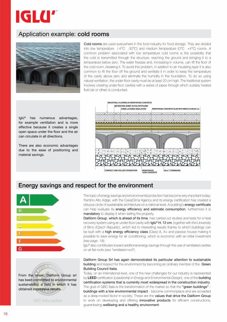
Application example: cold rooms
IGLU’® FORMWORKREINFORCED LEAN CONCRETE
COMPACT AND ROLLED FOUNDATION
INDUSTRIAL FLOORING IN REINFORCED CONCRETE
REINFORCED CONCRETE SLAB WITH MESH Ø 6/20x20 cm
SEPARATING SHEET IN POLYETHYLENE
THREE LAYERED INSULATION
Iglù® has numerous advantages,
for example ventilation and is more
effective because it creates a single
open space under the floor and the air
can circulate in all directions.
There are also economic advantages
due to the ease of positioning and
material savings.
Cold rooms are used everywhere in the food industry for food storage. They are divided
into low temperature (-4°C -30°C) and medium temperature (0°C +4°C) rooms. A
common problem associated with low temperature cold rooms is the possibility that
the cold is transmitted through the structure, reaching the ground and bringing it to a
temperature below zero. The water freezes and, increasing in volume, can lift the fl oor of
the cold room, breaking it. To avoid this problem, in addition to an insulating layer it is also
common to lift the fl oor off the ground and ventilate it in order to keep the temperature
of the cavity above zero and eliminate the humidity in the foundation. To do so using
natural ventilation, the under-fl oor cavity must be at least 20 cm high. The traditional system
involves creating under-fl oor cavities with a series of pipes through which suitably heated
fl uid (air or other) is conducted.
The topic of energy savings and environmental protection has become very important today;
Trentino Alto Adige, with the CasaClima Agency and its energy certifi cation has created a
virtuous circle of sustainable architecture on a national level. A building's energy certificate
can help evaluate its energy efficiency and estimate consumption, furthermore it is
mandatory to display it when selling the property.
Daliform Group, which is ahead of its time, has carried out studies and tests for a heat
recovery system using an under-fl oor cavity with Iglù® H. 12 cm, together with the University
of Brno (Czech Republic), which led to interesting results thanks to which buildings can
be built with a high energy efficiency class (Class A, A+ and passive house) making it
possible to save energy for air conditioning, which is economic with an initial investment
(see page 18).
Iglu® also contributes toward additional energy savings through the use of ventilated cavities
on all fl at roofs (see "ventilated roof").
Daliform Group Srl has again demonstrated its particular attention to sustainable
building and respect for the environment by becoming an ordinary member of the Green
Building Council Italia.
Today, on an international level, one of the new challenges for our industry is represented
by LEED certifi cation (Leadership in Energy and Environmental Design), one of the building
certification systems that is currently most widespread in the construction industry.
The goal of GBC Italia is the transformation of the market so that the “green buildings” -
buildings with a low environmental impact - become commonplace and are accepted
as a deep-rooted factor in society. These are the values that drive the Daliform Group
to work on developing and offering innovative products for effi cient constructions,
guaranteeing wellbeing and a healthy environment.
Energy savings and respect for the environment
From the onset, Daliform Group srl
has been committed to environmental
sustainability, a field in which it has
obtained impressive results.
17
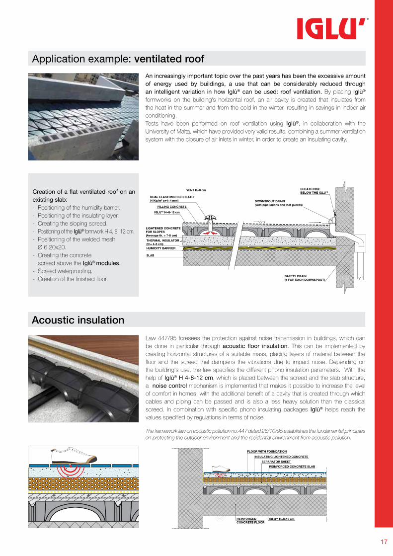
Application example: ventilated roof
SHEATH RISEBELOW THE IGLU’®
DOWNSPOUT DRAIN(with pipe unions and leaf guards)
VENT D=8 cm
IGLU’® H=8-12 cm
DUAL ELASTOMERIC SHEATH(4 Kg/m2 s=4+4 mm)
LIGHTENED CONCRETEFOR SLOPES(Average th. = 7-8 cm)
THERMAL INSULATOR(th= 4-5 cm) HUMIDITY BARRIER
SLAB
SAFETY DRAIN(1 FOR EACH DOWNSPOUT)
FILLING CONCRETE
Acoustic insulation
Law 447/95 foresees the protection against noise transmission in buildings, which can
be done in particular through acoustic floor insulation. This can be implemented by
creating horizontal structures of a suitable mass, placing layers of material between the
fl oor and the screed that dampens the vibrations due to impact noise. Depending on
the building's use, the law specifi es the different phono insulation parameters. With the
help of Iglù® H 4-8-12 cm, which is placed between the screed and the slab structure,
a noise control mechanism is implemented that makes it possible to increase the level
of comfort in homes, with the additional benefi t of a cavity that is created through which
cables and piping can be passed and is also a less heavy solution than the classical
screed. In combination with specifi c phono insulating packages Iglù® helps reach the
values specifi ed by regulations in terms of noise.
REINFORCED CONCRETE SLAB
SEPARATOR SHEET
INSULATING LIGHTENED CONCRETE
FLOOR WITH FOUNDATION
IGLU’® H=8-12 cmREINFORCED CONCRETE FLOOR
Creation of a flat ventilated roof on an
existing slab:
- Positioning of the humidity barrier.
- Positioning of the insulating layer.
- Creating the sloping screed.
- Positioning of the Iglù® formwork H 4, 8, 12 cm.
- Positioning of the welded mesh
Ø 6 20x20.
- Creating the concrete
screed above the Iglù® modules.
- Screed waterproofi ng.
- Creation of the fi nished fl oor.
An increasingly important topic over the past years has been the excessive amount
of energy used by buildings, a use that can be considerably reduced through
an intelligent variation in how Iglù® can be used: roof ventilation. By placing Iglù®
formworks on the building's horizontal roof, an air cavity is created that insulates from
the heat in the summer and from the cold in the winter, resulting in savings in indoor air
conditioning.
Tests have been performed on roof ventilation using Iglù®, in collaboration with the
University of Malta, which have provided very valid results, combining a summer ventilation
system with the closure of air inlets in winter, in order to create an insulating cavity.
The framework law on acoustic pollution no.447 dated 26/10/95 establishes the fundamental principles
on protecting the outdoor environment and the residential environment from acoustic pollution.
18
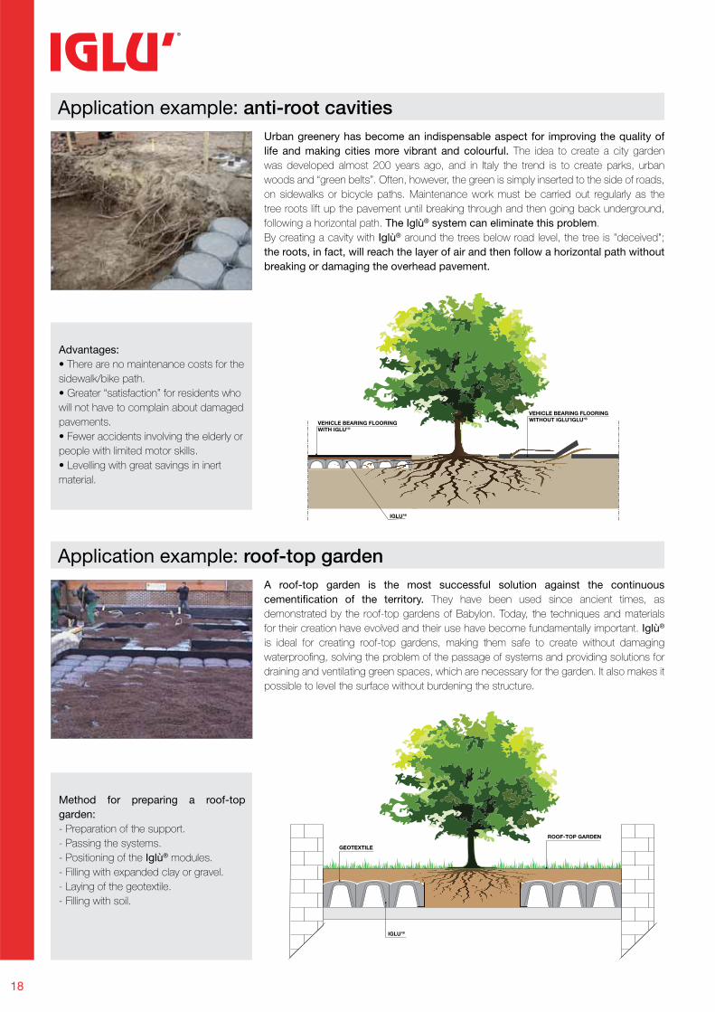
Application example: anti-root cavities
Advantages:
• There are no maintenance costs for the
sidewalk/bike path.
• Greater “satisfaction” for residents who
will not have to complain about damaged
pavements.
• Fewer accidents involving the elderly or
people with limited motor skills.
• Levelling with great savings in inert
material.
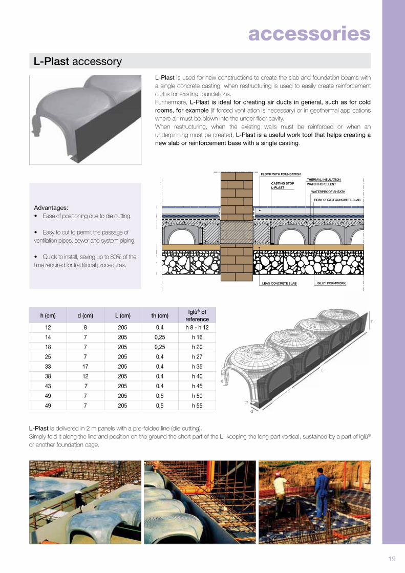
Method for preparing a roof-top
garden:
- Preparation of the support.
- Passing the systems.
- Positioning of the Iglù® modules.
- Filling with expanded clay or gravel.
- Laying of the geotextile.
- Filling with soil.
Urban greenery has become an indispensable aspect for improving the quality of
life and making cities more vibrant and colourful. The idea to create a city garden
was developed almost 200 years ago, and in Italy the trend is to create parks, urban
woods and “green belts”. Often, however, the green is simply inserted to the side of roads,
on sidewalks or bicycle paths. Maintenance work must be carried out regularly as the
tree roots lift up the pavement until breaking through and then going back underground,
following a horizontal path. The Iglù® system can eliminate this problem.
By creating a cavity with Iglù® around the trees below road level, the tree is "deceived";
the roots, in fact, will reach the layer of air and then follow a horizontal path without
breaking or damaging the overhead pavement.
Application example: roof-top gardenA roof-top garden is the most successful solution against the continuous
cementification of the territory. They have been used since ancient times, as
demonstrated by the roof-top gardens of Babylon. Today, the techniques and materials
for their creation have evolved and their use have become fundamentally important. Iglù®
is ideal for creating roof-top gardens, making them safe to create without damaging
waterproofi ng, solving the problem of the passage of systems and providing solutions for
draining and ventilating green spaces, which are necessary for the garden. It also makes it
possible to level the surface without burdening the structure.
IGLU’®
VEHICLE BEARING FLOORINGWITH IGLU’®
VEHICLE BEARING FLOORINGWITHOUT IGLU’IGLU’®
GEOTEXTILE
ROOF-TOP GARDEN
IGLU’®
19
Advantages:
• Ease of positioning due to die cutting.
• Easy to cut to permit the passage of
ventilation pipes, sewer and system piping.
• Quick to install, saving up to 80% of the
time required for traditional procedures.
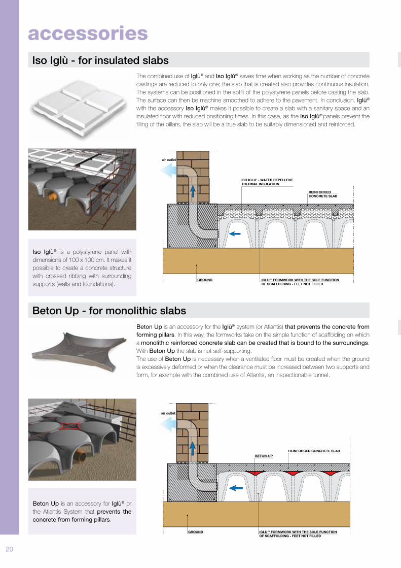
L-Plast accessory
L-Plast is used for new constructions to create the slab and foundation beams with
a single concrete casting; when restructuring is used to easily create reinforcement
curbs for existing foundations.
Furthermore, L-Plast is ideal for creating air ducts in general, such as for cold
rooms, for example (if forced ventilation is necessary) or in geothermal applications
where air must be blown into the under-fl oor cavity.
When restructuring, when the existing walls must be reinforced or when an
underpinning must be created, L-Plast is a useful work tool that helps creating a
new slab or reinforcement base with a single casting.
FLOOR WITH FOUNDATION
REINFORCED CONCRETE SLAB
IGLU'® FORMWORKLEAN CONCRETE SLAB
THERMAL INSULATION
WATER REPELLENT
WATERPROOF SHEATH
CASTING STOPL-PLAST
L-Plast is delivered in 2 m panels with a pre-folded line (die cutting).
Simply fold it along the line and position on the ground the short part of the L, keeping the long part vertical, sustained by a part of Iglù®
or another foundation cage.
h (cm)
12
14
18
25
33
38
43
49
49
8
7
7
7
17
12
7
7
7
205
205
205
205
205
205
205
205
205
0,4
0,25
0,25
0,4
0,4
0,4
0,4
0,5
0,5
h 8 - h 12
h 16
h 20
h 27
h 35
h 40
h 45
h 50
h 55
d (cm) L (cm) th (cm)Iglù® of
reference
accessories
th
d
h
L
20
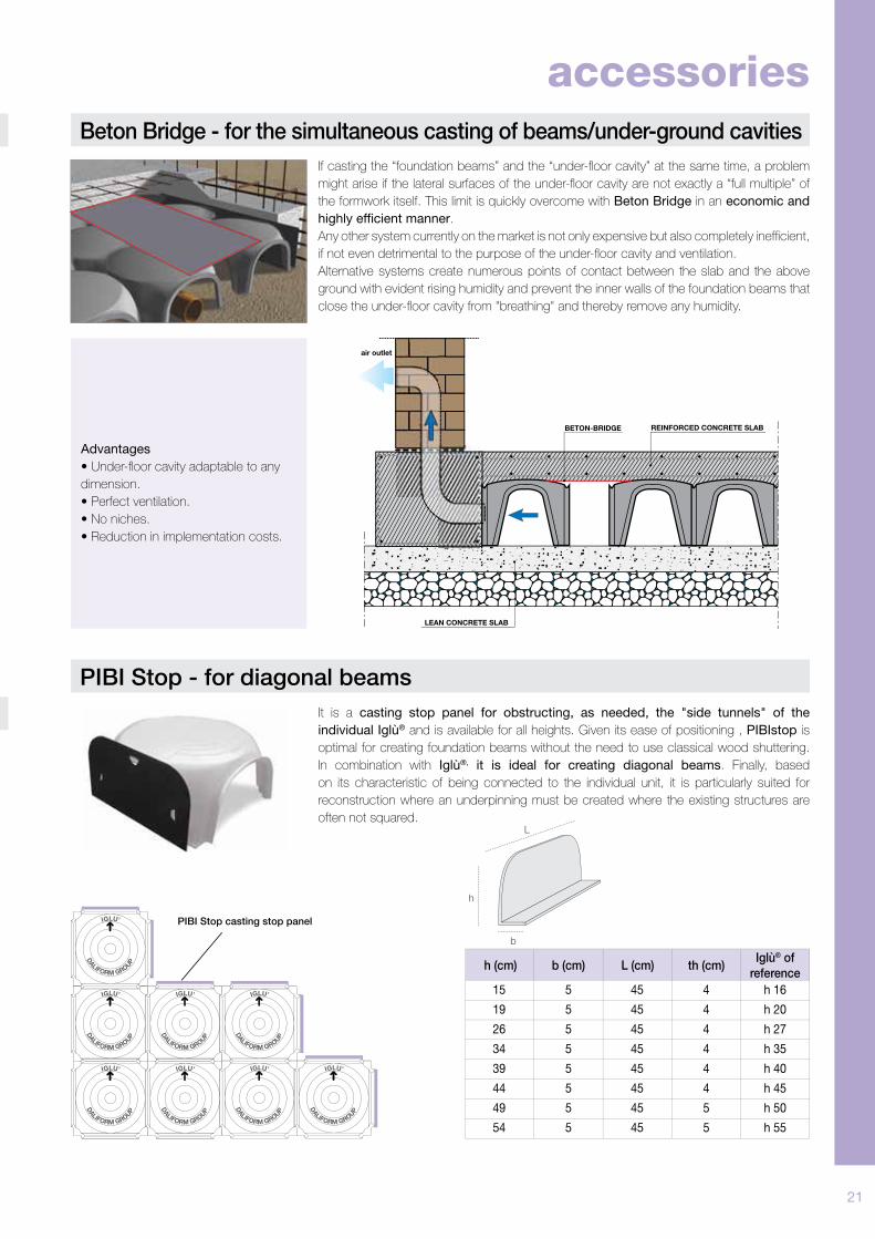
Iso Iglù - for insulated slabs
Beton Up - for monolithic slabs
The combined use of Iglù® and Iso Iglù® saves time when working as the number of concrete
castings are reduced to only one; the slab that is created also provides continuous insulation.
The systems can be positioned in the soffi t of the polystyrene panels before casting the slab.
The surface can then be machine smoothed to adhere to the pavement. In conclusion, Iglù®
with the accessory Iso Iglù® makes it possible to create a slab with a sanitary space and an
insulated fl oor with reduced positioning times. In this case, as the Iso Iglù® panels prevent the
fi lling of the pillars, the slab will be a true slab to be suitably dimensioned and reinforced.
Beton Up is an accessory for the Iglù® system (or Atlantis) that prevents the concrete from
forming pillars. In this way, the formworks take on the simple function of scaffolding on which
a monolithic reinforced concrete slab can be created that is bound to the surroundings.
With Beton Up the slab is not self-supporting.
The use of Beton Up is necessary when a ventilated fl oor must be created when the ground
is excessively deformed or when the clearance must be increased between two supports and
form, for example with the combined use of Atlantis, an inspectionable tunnel.
REINFORCEDCONCRETE SLAB
ISO IGLU’ - WATER REPELLENT THERMAL INSULATION
air outlet
GROUND IGLU'® FORMWORK WITH THE SOLE FUNCTION OF SCAFFOLDING - FEET NOT FILLED
Iso Iglù® is a polystyrene panel with
dimensions of 100 x 100 cm. It makes it
possible to create a concrete structure
with crossed ribbing with surrounding
supports (walls and foundations).
Beton Up is an accessory for Iglù® or
the Atlantis System that prevents the
concrete from forming pillars.
BETON-UPREINFORCED CONCRETE SLAB
IGLU'® FORMWORK WITH THE SOLE FUNCTIONOF SCAFFOLDING - FEET NOT FILLED
GROUND
air outlet
accessories
21
h
L
b
Beton Bridge - for the simultaneous casting of beams/under-ground cavities
Advantages
• Under-fl oor cavity adaptable to any
dimension.
• Perfect ventilation.
• No niches.
• Reduction in implementation costs.
PIBI Stop - for diagonal beams
It is a casting stop panel for obstructing, as needed, the "side tunnels" of the
individual Iglù® and is available for all heights. Given its ease of positioning , PIBIstop is
optimal for creating foundation beams without the need to use classical wood shuttering.
In combination with Iglù®, it is ideal for creating diagonal beams. Finally, based
on its characteristic of being connected to the individual unit, it is particularly suited for
reconstruction where an underpinning must be created where the existing structures are
often not squared.
If casting the “foundation beams” and the “under-fl oor cavity” at the same time, a problem
might arise if the lateral surfaces of the under-fl oor cavity are not exactly a “full multiple” of
the formwork itself. This limit is quickly overcome with Beton Bridge in an economic and
highly efficient manner.
Any other system currently on the market is not only expensive but also completely ineffi cient,
if not even detrimental to the purpose of the under-fl oor cavity and ventilation.
Alternative systems create numerous points of contact between the slab and the above
ground with evident rising humidity and prevent the inner walls of the foundation beams that
close the under-fl oor cavity from "breathing" and thereby remove any humidity.
REINFORCED CONCRETE SLAB
LEAN CONCRETE SLAB
BETON-BRIDGE
air outlet
h (cm)
15
19
26
34
39
44
49
54
5
5
5
5
5
5
5
5
45
45
45
45
45
45
45
45
4
4
4
4
4
4
5
5
h 16
h 20
h 27
h 35
h 40
h 45
h 50
h 55
b (cm) L (cm) th (cm)Iglù® of
reference
PIBI Stop casting stop panel
accessories
8
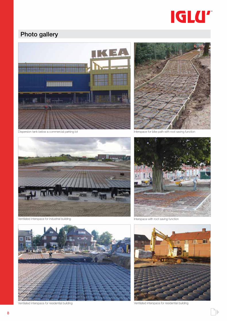
Ventilated interspace for residential building
Dispersion tank below a commercial parking lot
Interspace with root saving function
Ventilated interspace for residential building
Ventilated interspace for industrial building
Interspace for bike path with root saving function
Photo gallery
13
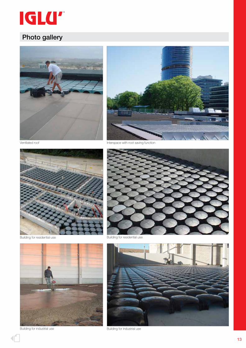
Building for industrial use
Interspace with root saving function
Building for residential use
Building for industrial use
Building for residential use
Ventilated roof
Photo gallery
22
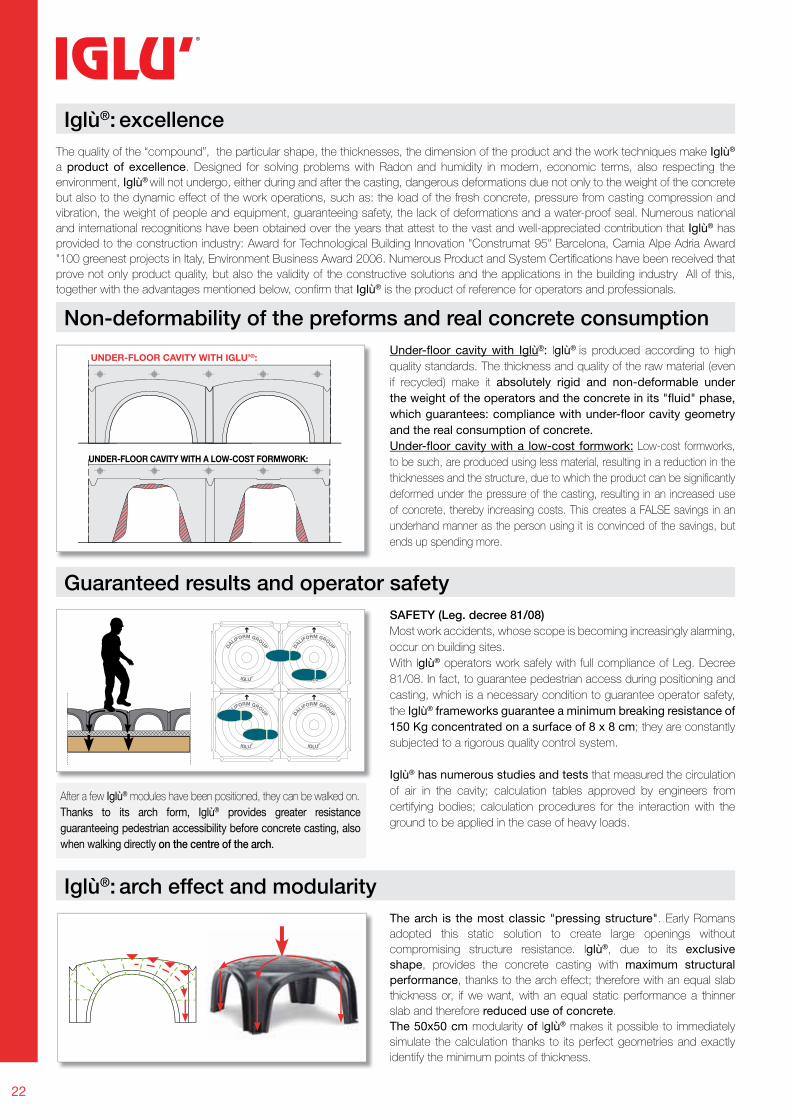
Iglù®: excellence
Non-deformability of the preforms and real concrete consumption
Iglù®: arch effect and modularity
Under-floor cavity with Iglù®: Iglù® is produced according to high
quality standards. The thickness and quality of the raw material (even
if recycled) make it absolutely rigid and non-deformable under
the weight of the operators and the concrete in its "fluid" phase,
which guarantees: compliance with under-floor cavity geometry
and the real consumption of concrete.
Under-floor cavity with a low-cost formwork: Low-cost formworks,
to be such, are produced using less material, resulting in a reduction in the
thicknesses and the structure, due to which the product can be signifi cantly
deformed under the pressure of the casting, resulting in an increased use
of concrete, thereby increasing costs. This creates a FALSE savings in an
underhand manner as the person using it is convinced of the savings, but
ends up spending more.
The quality of the “compound”, the particular shape, the thicknesses, the dimension of the product and the work techniques make Iglù®
a product of excellence. Designed for solving problems with Radon and humidity in modern, economic terms, also respecting the
environment, Iglù® will not undergo, either during and after the casting, dangerous deformations due not only to the weight of the concrete
but also to the dynamic effect of the work operations, such as: the load of the fresh concrete, pressure from casting compression and
vibration, the weight of people and equipment, guaranteeing safety, the lack of deformations and a water-proof seal. Numerous national
and international recognitions have been obtained over the years that attest to the vast and well-appreciated contribution that Iglù® has
provided to the construction industry: Award for Technological Building Innovation "Construmat 95" Barcelona, Carnia Alpe Adria Award
"100 greenest projects in Italy, Environment Business Award 2006. Numerous Product and System Certifi cations have been received that
prove not only product quality, but also the validity of the constructive solutions and the applications in the building industry All of this,
together with the advantages mentioned below, confi rm that Iglù® is the product of reference for operators and professionals.
The arch is the most classic "pressing structure". Early Romans
adopted this static solution to create large openings without
compromising structure resistance. Iglù®, due to its exclusive
shape, provides the concrete casting with maximum structural
performance, thanks to the arch effect; therefore with an equal slab
thickness or, if we want, with an equal static performance a thinner
slab and therefore reduced use of concrete.
The 50x50 cm modularity of Iglù® makes it possible to immediately
simulate the calculation thanks to its perfect geometries and exactly
identify the minimum points of thickness.
Guaranteed results and operator safety
SAFETY (Leg. decree 81/08)
Most work accidents, whose scope is becoming increasingly alarming,
occur on building sites.
With Iglù® operators work safely with full compliance of Leg. Decree
81/08. In fact, to guarantee pedestrian access during positioning and
casting, which is a necessary condition to guarantee operator safety,
the Iglù® frameworks guarantee a minimum breaking resistance of
150 Kg concentrated on a surface of 8 x 8 cm; they are constantly
subjected to a rigorous quality control system.
Iglù® has numerous studies and tests that measured the circulation
of air in the cavity; calculation tables approved by engineers from
certifying bodies; calculation procedures for the interaction with the
ground to be applied in the case of heavy loads.
After a few Iglù® modules have been positioned, they can be walked on.
Thanks to its arch form, Iglù® provides greater resistance
guaranteeing pedestrian accessibility before concrete casting, also
when walking directly on the centre of the arch.
UNDER-FLOOR CAVITY WITH IGLU’®:
UNDER-FLOOR CAVITY WITH A LOW-COST FORMWORK:
23
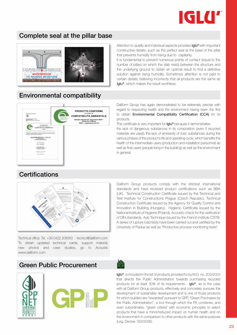
Complete seal at the pillar base
Green Public Procurement
Environmental compatibility
Iglù®, is included in the list of products provided for by M.D. no. 203/2003
that directs the Public Administration towards purchasing recycled
products for at least 30% of its requirements. Iglù®, as is the case
with all Daliform Group products, effectively and concretely pursues the
development of sustainable development and is one of those products
for which builders are "rewarded" pursuant to GPP, “Green Purchases by
the Public Administration”, a tool through which the PA combines, and
even subordinates, “green criteria” with economic principles to select
products that have a minor/reduced impact on human health and on
the environment in comparison to other products with the same purpose
(Leg. Decree 163/2006).
Daliform Group has again demonstrated to be extremely precise with
regard to respecting health and the environment having been the fi rst
to obtain Environmental Compatibility Certification (CCA) for its
products.
This certifi cate is very important for Iglu® because it demonstrates:
the lack of dangerous substances in its composition (even if recycled
materials are used); the lack of emissivity of toxic substances during the
various phases of the product's life and operating cycle, which benefi ts the
health of the intermediate users (production and installation personnel) as
well as fi nal users (people living in the building) as well as the environment
in general.
Attention to quality and individual aspects provides Iglù® with important
constructive details, such as the perfect seal at the base of the pillar
that prevents humidity from rising due to capillarity.
It is fundamental to prevent numerous points of contact (equal to the
number of pillars on which the slab rests) between the structure and
the underlying ground to obtain an optimal result to fi nd a defi nitive
solution against rising humidity. Sometimes attention is not paid to
certain details, believing incorrectly that all products are the same as
Iglu®, which makes the result worthless.
Certifi cationsDaliform Group products comply with the strictest international
standards and have received product certifi cations such as BBA
(UK), Technical Construction Certifi cate issued by the Technical and
Test Institute for Constructions Prague (Czech Republic), Technical
Construction Certifi cate issued by the Agency for Quality Control and
Innovation in Building (Hungary), Hygienic Certifi cate issued by the
National Institute of Hygiene (Poland), Acoustic check for the verifi cation
of DIN standards, Avis Technique issued by the French institute CSTB.
A series of rupture load tests have been carried out and certifi ed by the
University of Padua as well as "Productive process monitoring tests".
Technical offi ce: Tel. +39 0422 208350 - [email protected]
To obtain updated technical cards, support material,
new photos and case studies, go to Acoustic
www.daliform.com
WATERPROOFTO RAISING MOISTURE
24
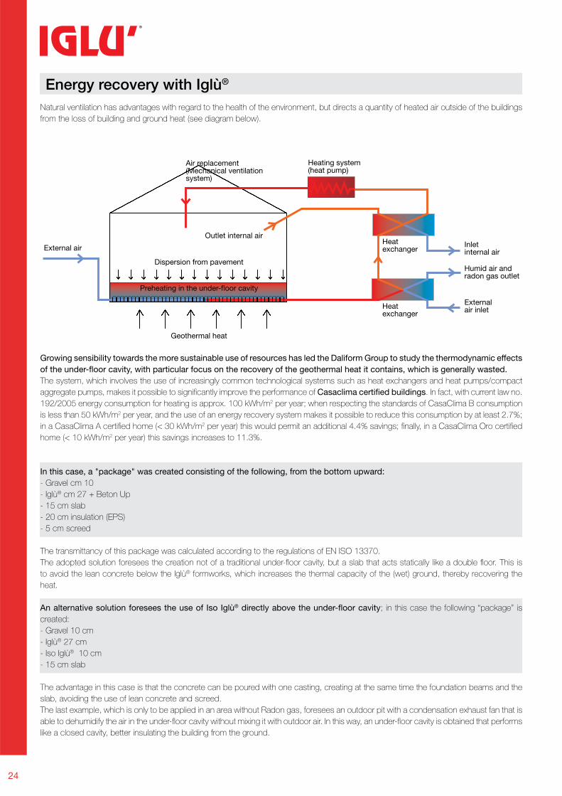
Energy recovery with Iglù®
Natural ventilation has advantages with regard to the health of the environment, but directs a quantity of heated air outside of the buildings
from the loss of building and ground heat (see diagram below).
Growing sensibility towards the more sustainable use of resources has led the Daliform Group to study the thermodynamic effects
of the under-floor cavity, with particular focus on the recovery of the geothermal heat it contains, which is generally wasted.
The system, which involves the use of increasingly common technological systems such as heat exchangers and heat pumps/compact
aggregate pumps, makes it possible to signifi cantly improve the performance of Casaclima certified buildings. In fact, with current law no.
192/2005 energy consumption for heating is approx. 100 kWh/m2 per year; when respecting the standards of CasaClima B consumption
is less than 50 kWh/m2 per year, and the use of an energy recovery system makes it possible to reduce this consumption by at least 2.7%;
in a CasaClima A certifi ed home (< 30 kWh/m2 per year) this would permit an additional 4.4% savings; fi nally, in a CasaClima Oro certifi ed
home (< 10 kWh/m2 per year) this savings increases to 11.3%.
In this case, a "package" was created consisting of the following, from the bottom upward:
- Gravel cm 10
- Iglù® cm 27 + Beton Up
- 15 cm slab
- 20 cm insulation (EPS)
- 5 cm screed
The transmittancy of this package was calculated according to the regulations of EN ISO 13370.
The adopted solution foresees the creation not of a traditional under-fl oor cavity, but a slab that acts statically like a double fl oor. This is
to avoid the lean concrete below the Iglù® formworks, which increases the thermal capacity of the (wet) ground, thereby recovering the
heat.
An alternative solution foresees the use of Iso Iglù® directly above the under-floor cavity; in this case the following “package” is
created:
- Gravel 10 cm
- Iglù® 27 cm
- Iso Iglù® 10 cm
- 15 cm slab
The advantage in this case is that the concrete can be poured with one casting, creating at the same time the foundation beams and the
slab, avoiding the use of lean concrete and screed.
The last example, which is only to be applied in an area without Radon gas, foresees an outdoor pit with a condensation exhaust fan that is
able to dehumidify the air in the under-fl oor cavity without mixing it with outdoor air. In this way, an under-fl oor cavity is obtained that performs
like a closed cavity, better insulating the building from the ground.
External air
Outlet internal air
Dispersion from pavement
Geothermal heat
Air replacement(Mechanical ventilationsystem)
Heating system(heat pump)
Heatexchanger
Inletinternal air
Externalair inlet
Humid air andradon gas outlet
Heatexchanger
Preheating in the under-floor cavity
25
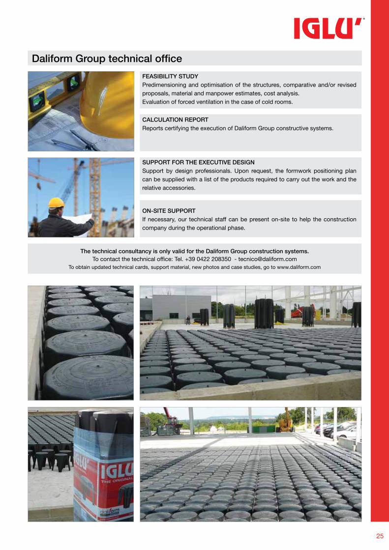
Daliform Group technical offi ce
The technical consultancy is only valid for the Daliform Group construction systems.To contact the technical office: Tel. +39 0422 208350 - [email protected]
To obtain updated technical cards, support material, new photos and case studies, go to www.daliform.com
FEASIBILITY STUDYPredimensioning and optimisation of the structures, comparative and/or revised
proposals, material and manpower estimates, cost analysis.
Evaluation of forced ventilation in the case of cold rooms.
SUPPORT FOR THE EXECUTIVE DESIGNSupport by design professionals. Upon request, the formwork positioning plan
can be supplied with a list of the products required to carry out the work and the
relative accessories.
CALCULATION REPORTReports certifying the execution of Daliform Group constructive systems.
ON-SITE SUPPORTIf necessary, our technical staff can be present on-site to help the construction
company during the operational phase.
26
8,20/9,60 x 2,45
6,20 x 2,45
8,40 x 2,45 7,20 x 2,45
13,60 x 2,45
20 feet
40 feet
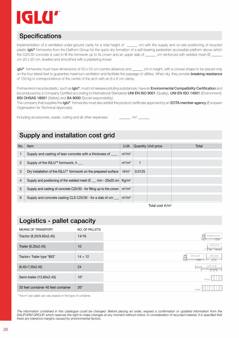
Specifi cations
Supply and installation cost grid
Logistics - pallet capacity
Implementation of a ventilated under-ground cavity for a total height of ______ cm with the supply and on-site positioning of recycled
plastic Iglù® formworks from the Daliform Group for the quick dry formation of a self-bearing pedestrian accessible platform above which
the C25/30 concrete is cast to fi ll the formwork up to its crown and an upper slab of ______ cm reinforced with welded mesh Ø ______
cm 20 x 20 cm, levelled and smoothed with a plastering trowel.
Iglù® formworks must have dimensions of 50 x 50 cm (centre distance) and ______ cm in height, with a convex shape to be placed only
on the four lateral feet to guarantee maximum ventilation and facilitate the passage of utilities. When dry, they provide breaking resistance
of 150 kg in correspondence of the centre of the arch with an 8 x 8 cm clamp.
Formworks in recycle plastic, such as Iglù®, must not release polluting substances, have an Environmental Compatibility Certification and
be produced by a Company Certifi ed according to International Standards UNI EN ISO 9001 (Quality), UNI EN ISO 14001 (Environment);
BSI OHSAS 18001 (Safety) and SA 8000 (Social responsibility).
The company that supplies the Iglù® formworks must also exhibit the product certifi cate approved by an EOTA member agency (European
Organisation for Technical Approvals).
Including accessories, waste, cutting and all other expenses: ______ /m2 ______
The information contained in this catalogue could be changed. Before placing an order, request a confi rmation or updated information from the DALIFORM GROUP, which reserves the right to make changes at any moment without notice. In consideration of recycled material, it is specifi ed that there are tolerance margins caused by environmental factors.
Tractor (8.20/9.60x2.45)
Trailer (6.20x2.45)
Tractor+ Trailer type “BIG”
(8.40+7.20x2.45)
Semi-trailer (13.60x2.45)
20 feet container 40 feet container
14/16
10
14 + 12
24
10*
20*
Total cost €/m2
MEANS OF TRANSPORT NO. OF PALLETS
No. Item U.M. Quantity Unit price Total
1 Supply and casting of lean concrete with a thickness of ____ m3/m2
2 Supply of the IGLU’® formwork, h ___ m2/m2 1
3 Dry installation of the IGLU’® formwork on the prepared surface H/m2 0.0125
4 Supply and positioning of the welded mesh Ø ___ mm - 20x20 cm Kg/m2
5 Supply and casting of concrete C25/30 - for filling up to the crown m3/m2
6 Supply and concrete casting CLS C25/30 - for a slab of cm ___ m3/m2
* the m2 per pallet can vary based on the type of container.
www.daliform.com
DG
_IG
- R
ev. 0
7_03
-13
Mad
e in
Ita
ly
GBC Italia partner
Tel. +39 0422 2083 - Fax +39 0422 800234
[email protected] - www.daliform.com
Via Serenissima, 30 - 31040
Gorgo al Monticano (TV) - Italy