IEEE TRANSACTIONS ON VISUALIZATION AND … · 3D Virtual and Mixed Environments ... and/or gaze....
6
IEEE TRANSACTIONS ON VISUALIZATION AND COMPUTER GRAPHICS, MANUSCRIPT ID 1 Enhancing Interactivity within 3D Virtual and Mixed Environments – A First Cut Robert T. Casey, Member, IEEE, IEEE-RAS Abstract—As large-scale interfaces for displaying scientific data advance, a call is made for novel schemes for interacting with such data beyond the traditional, repetitive interface of the mouse and keyboard. The motion capture technology incorporated extensively by filmmakers offers one option for such an interface. However, a user of such a system must usually don obtrusive equipment such as gloves or even full body suits in order to facilitate effective tracking of the appropriate portions of the body. A more user-friendly approach would obviate the need for such equipment, tracking the user passively with highly functional imaging devices, for example. This paper presents an outline for such a tracking system as well as preliminary work towards its construction. Index Terms—Artificial, augmented, and virtual realities; computer vision, large-scale user interfaces, tracking, visual hulls. —————————— —————————— 1 INTRODUCTION magine a user entering a U-shaped room whose walls are lined with monitors. Visual data spans this monitor wall, and one section of the wall catches the user's inter- est. The user turns his or her head to focus upon one area of the display, a movement captured by a nearby bank of cameras. This camera system immediately informs that region of the display to change its resolution and magnifi- cation to show greater detail. Next, the user makes a fo- cused gesture with his or her hands, and the display again updates itself in real-time, displaying some new aspect of the data or completely new data. I Such a scenario for interacting with large-scale visual data is no longer restricted to the fantasy domain of movies like Minority Report. Indeed, such a setup might be effected through traditional motion capture technology commonly employed by filmmakers and video game pro- duction houses. However, these interfaces usually call for the user to wear obtrusive equipment like gloves or even full body suits for tracking purposes. A more ideal ar- rangement would include passive tracking capabilities, such as through a computer vision system. This paper will outline key components and steps towards construct- ing such a system, as well as a new researcher's first cut at this problem. 2 DESIRED SYSTEM OUTLINE 2.1 Key components The first key attribute of an effective user interface fulfill- ing the above goals is that the system must be real-time. Delays and excessive latency in a system's response time serve only to frustrate users and to thwart the long-term effectiveness of the interface. The next important aspect of the system is that the in- terface be passive. Motion capture technology, while ef- fective, needlessly burdens the user with bulky equip- ment which stymies natural movement. A sophisticated computer vision system would ably serve this require- ment for a passive tracking system. Such a computer vision system would ideally fulfill three additional requirements. First, the system would need to offer sufficient accuracy and measurement fi- delity in order to perform tracking of a person's gestures and/or gaze. Features tracked include the position and orientation, or pose, of a user's arm, hand, fingers, etc. within the world coordinate system of the interactive dis- play environment. For high fidelity systems, the ability to track at least some of the multiple degrees of freedom presented by the human hand would increase the capabil- ities and sophistication of the resulting interface. Secondly, the computer vision system should either be robust to changing lighting conditions or perform its du- ties within a controlled lighting environment. The latter could be accomplished through infrared lighting, special- ized backdrops, and other devices. Lastly, it would be highly desirable for the system to be able to track multiple users simultaneously. This would greatly increase the value of the interface and display by fostering collaboration among researchers in understand- ing visual data. Such a requirement increases the sophis- tication of the desired system, as the system would need to handle occlusions and concavities introduced by the presence of multiple users. xxxx-xxxx/0x/$xx.00 © 2010 IEEE ———————————————— • R.T. Casey is with the Department of Computer Engineering, UC Santa Cruz, Santa Cruz, CA 95046. Email: [email protected].
Transcript of IEEE TRANSACTIONS ON VISUALIZATION AND … · 3D Virtual and Mixed Environments ... and/or gaze....

IEEE TRANSACTIONS ON VISUALIZATION AND COMPUTER GRAPHICS, MANUSCRIPT ID 1
Enhancing Interactivity within 3D Virtual and Mixed Environments –
A First CutRobert T. Casey, Member, IEEE, IEEERAS
Abstract—As largescale interfaces for displaying scientific data advance, a call is made for novel schemes for interacting with such data beyond the traditional, repetitive interface of the mouse and keyboard. The motion capture technology incorporated extensively by filmmakers offers one option for such an interface. However, a user of such a system must usually don obtrusive equipment such as gloves or even full body suits in order to facilitate effective tracking of the appropriate portions of the body. A more userfriendly approach would obviate the need for such equipment, tracking the user passively with highly functional imaging devices, for example. This paper presents an outline for such a tracking system as well as preliminary work towards its construction.
Index Terms—Artificial, augmented, and virtual realities; computer vision, largescale user interfaces, tracking, visual hulls.
—————————— ——————————
1 INTRODUCTION
magine a user entering a Ushaped room whose walls are lined with monitors. Visual data spans this monitor
wall, and one section of the wall catches the user's interest. The user turns his or her head to focus upon one area of the display, a movement captured by a nearby bank of cameras. This camera system immediately informs that region of the display to change its resolution and magnification to show greater detail. Next, the user makes a focused gesture with his or her hands, and the display again updates itself in realtime, displaying some new aspect of the data or completely new data.
I
Such a scenario for interacting with largescale visual data is no longer restricted to the fantasy domain of movies like Minority Report. Indeed, such a setup might be effected through traditional motion capture technology commonly employed by filmmakers and video game production houses. However, these interfaces usually call for the user to wear obtrusive equipment like gloves or even full body suits for tracking purposes. A more ideal arrangement would include passive tracking capabilities, such as through a computer vision system. This paper will outline key components and steps towards constructing such a system, as well as a new researcher's first cut at this problem.
2 DESIRED SYSTEM OUTLINE
2.1 Key componentsThe first key attribute of an effective user interface fulfilling the above goals is that the system must be realtime. Delays and excessive latency in a system's response time serve only to frustrate users and to thwart the longterm
effectiveness of the interface. The next important aspect of the system is that the in
terface be passive. Motion capture technology, while effective, needlessly burdens the user with bulky equipment which stymies natural movement. A sophisticated computer vision system would ably serve this requirement for a passive tracking system.
Such a computer vision system would ideally fulfill three additional requirements. First, the system would need to offer sufficient accuracy and measurement fidelity in order to perform tracking of a person's gestures and/or gaze. Features tracked include the position and orientation, or pose, of a user's arm, hand, fingers, etc. within the world coordinate system of the interactive display environment. For high fidelity systems, the ability to track at least some of the multiple degrees of freedom presented by the human hand would increase the capabilities and sophistication of the resulting interface.
Secondly, the computer vision system should either be robust to changing lighting conditions or perform its duties within a controlled lighting environment. The latter could be accomplished through infrared lighting, specialized backdrops, and other devices.
Lastly, it would be highly desirable for the system to be able to track multiple users simultaneously. This would greatly increase the value of the interface and display by fostering collaboration among researchers in understanding visual data. Such a requirement increases the sophistication of the desired system, as the system would need to handle occlusions and concavities introduced by the presence of multiple users.
xxxxxxxx/0x/$xx.00 © 2010 IEEE
————————————————
• R.T. Casey is with the Department of Computer Engineering, UC Santa Cruz, Santa Cruz, CA 95046. Email: [email protected].

2 IEEE TRANSACTIONS ON VISUALIZATION AND COMPUTER GRAPHICS
2.2 System Specifications and Relevant WorkWith enough cameras, data bandwidth, and processing
power behind the implementation, the visual hull concept [1] promises to fulfill many of the aforementioned requirements. Visual hulls are a shapefromsilhouette (SFS) technique which allow an approximate, 3D volume reconstruction of some desired scene object using a fixed number of 2D input images. This technique has been implemented in realtime according to a variety of unique approaches, including imagebased visual hulls [2], polyhedral visual hulls [3], GPUaccelerated hulls [4], and polyhedral hulls with a focus on hand gesture tracking [5].
Visual hull research in [25] demonstrated the viability of shapefromsilhouette techniques for meeting realtime requirements. Imagebased visual hulls [2], pioneered by Matusik et al, advanced a viewdependent representation using methods similar to raycasting for 3D volume reconstruction [6] from 2D binary images. Such a system offered reasonable frame rates coupled with a sufficiently accurate volume representation. Polyhedral visual hulls [3] extended Matusik's prior work to a viewindependent representation which enabled offloading of the rendering to hardware, due to the special design of the system's output (triangular primitives readily processed by modern graphics cards). This system offered even higher performance than the imagebased approach (15 fps vs. 8 fps). Li et al further raised the visual hull performance bar to 80 fps with their algorithm specially tailored for graphics card acceleration [4]. These examples amply demonstrate that visual hulls may be used in realtime systems.
In [5], Schlattmann and Klein presented a polyhedral hull implementation customized for the tracking of four specific hand gestures (“palm,” “picking,” and two varieties of “pointing”). Their system featured a novel controlled lighting scheme of infrared lights and a specialized backdrop to aid foreground/background segmentation, a key first step in the visual hull algorithm. Another impressive feature of the system was the ability to extract regions of interest using only three speciallypositioned cameras as the sensing modality. Thus polyhedral hulls, through the viewindependent nature of their representation, offer a 3D representation amenable for tracking purposes.
Yang et al [ 7] discuss the use of visual hulls in embedded devices to count persons in crowds in outdoor environments. Their system employed a resourcelight visual hull algorithm which could be run on small imaging devices in outdoor environments to track the number of persons in a particular area of interest.
Tracking a person's face, hands, and gestures has been covered extensively in the computer vision literature and continues to pose an unsolved problem to researchers. In [8], Erol et al present a review of advances and considerations for implementing a system which performs hand tracking for the purposes of humancomputer interaction (HCI). Specifically, Erol discusses two overarching techniques for using the hand as an input device: gesture classification and pose estimation.
Other considerations in designing largescale user in
terfaces and interactive displays are presented in works by Baker, et al, on the Coliseum system as well as camera and projector arrays [9][10].
3 PRELIMINARY SYSTEM IMPLEMENTATION
3.1 Imaging Considerations
3.1.1 IEEE 1394 InterfaceFirewire cameras, such as Apple's iSight and Uni
brain's Firei webcams, were selected as the input devices for these experiments due to the functionality provided within the IEEE 1394 device specification. Specifically, the ability to enumerate different devices on the bus as well as address each component individually is a key requirement for successful implementation of visual hulls.
Douxchamps [11] presents a useful library, libdc1394, which assists users with an API for communicating with IEEE 1394based cameras, as well as a Linuxbased GUI, Coriander [12], for quickly testing firewire cameras.
3.1.2 Camera CalibrationIn order to avail a vision system of sophisticated algo
rithms for data analysis and processing, the internal and external parameters of the imaging device must first be estimated. This process also facilitates the correction of defects, such as radial distortion, inherent in realworld optics.
Calibration is another aspect of computer vision experimentation which has been documented extensively in the literature. Zhengyou Zhang presents an excellent exposition on this topic [13], as well as Windowsbased software which implements his particular algorithm. Also, Schreiber and Baker [14] develop a rigorous approach to calibration which looks at special properties of the related homography matrices.
JeanYves Bouguet's presents a readytouse Matlab toolbox [15] which eases estimation of the relevant camera parameters. The author of this paper used this toolbox to calibrate the iSight camera. We illustrate a few snapshots of this process in the Figs. 1,2.
Fig. 1 Orientation of the calibration planes
ROBERT T. CASEY: ENHANCING INTERACTIVITY WITHIN 3D VIRTUAL AND MIXED ENVIRONMENTS – A FIRST CUT 3
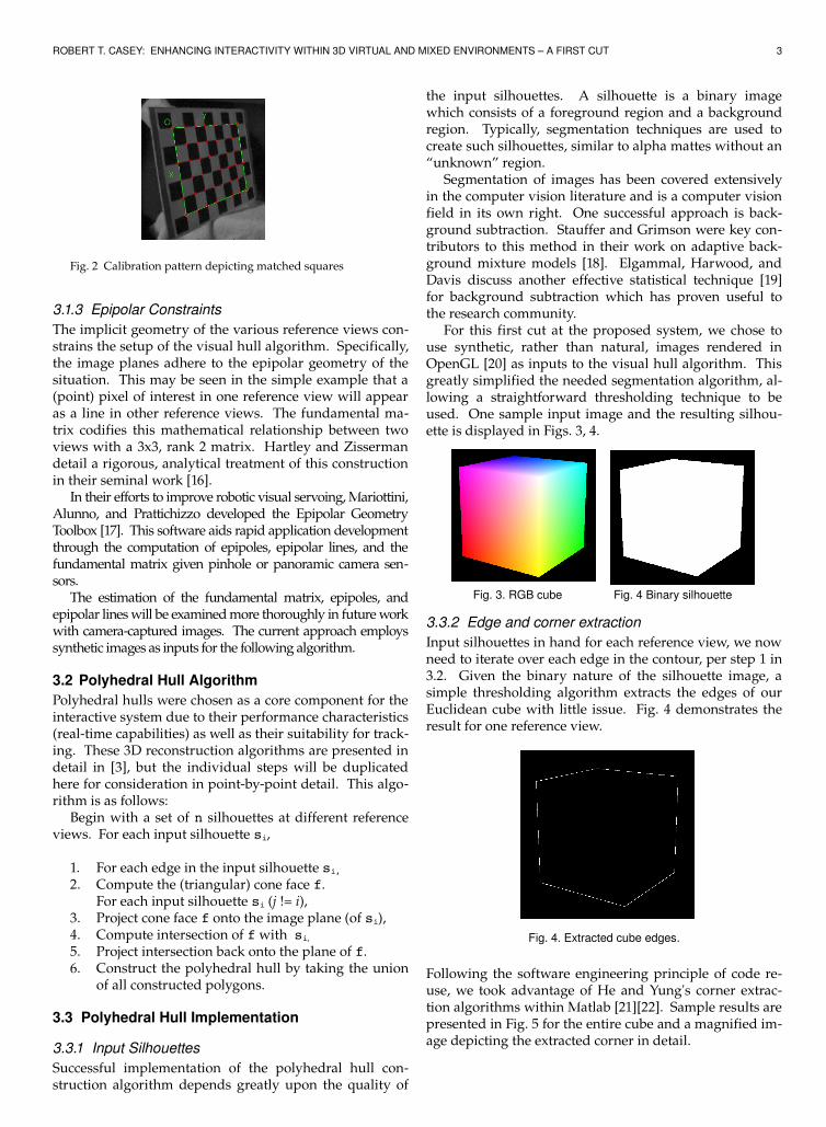
Fig. 2 Calibration pattern depicting matched squares
3.1.3 Epipolar ConstraintsThe implicit geometry of the various reference views constrains the setup of the visual hull algorithm. Specifically, the image planes adhere to the epipolar geometry of the situation. This may be seen in the simple example that a (point) pixel of interest in one reference view will appear as a line in other reference views. The fundamental matrix codifies this mathematical relationship between two views with a 3x3, rank 2 matrix. Hartley and Zisserman detail a rigorous, analytical treatment of this construction in their seminal work [16].
In their efforts to improve robotic visual servoing, Mariottini, Alunno, and Prattichizzo developed the Epipolar Geometry Toolbox [17]. This software aids rapid application development through the computation of epipoles, epipolar lines, and the fundamental matrix given pinhole or panoramic camera sensors.
The estimation of the fundamental matrix, epipoles, and epipolar lines will be examined more thoroughly in future work with cameracaptured images. The current approach employs synthetic images as inputs for the following algorithm.
3.2 Polyhedral Hull AlgorithmPolyhedral hulls were chosen as a core component for the interactive system due to their performance characteristics (realtime capabilities) as well as their suitability for tracking. These 3D reconstruction algorithms are presented in detail in [3], but the individual steps will be duplicated here for consideration in pointbypoint detail. This algorithm is as follows:
Begin with a set of n silhouettes at different reference views. For each input silhouette si,
1. For each edge in the input silhouette si, 2. Compute the (triangular) cone face f.
For each input silhouette si (j != i),3. Project cone face f onto the image plane (of si),4. Compute intersection of f with si,
5. Project intersection back onto the plane of f.6. Construct the polyhedral hull by taking the union
of all constructed polygons.
3.3 Polyhedral Hull Implementation
3.3.1 Input Silhouettes Successful implementation of the polyhedral hull construction algorithm depends greatly upon the quality of
the input silhouettes. A silhouette is a binary image which consists of a foreground region and a background region. Typically, segmentation techniques are used to create such silhouettes, similar to alpha mattes without an “unknown” region.
Segmentation of images has been covered extensively in the computer vision literature and is a computer vision field in its own right. One successful approach is background subtraction. Stauffer and Grimson were key contributors to this method in their work on adaptive background mixture models [18]. Elgammal, Harwood, and Davis discuss another effective statistical technique [19] for background subtraction which has proven useful to the research community.
For this first cut at the proposed system, we chose to use synthetic, rather than natural, images rendered in OpenGL [20] as inputs to the visual hull algorithm. This greatly simplified the needed segmentation algorithm, allowing a straightforward thresholding technique to be used. One sample input image and the resulting silhouette is displayed in Figs. 3, 4.
Fig. 3. RGB cube Fig. 4 Binary silhouette
3.3.2 Edge and corner extractionInput silhouettes in hand for each reference view, we now need to iterate over each edge in the contour, per step 1 in 3.2. Given the binary nature of the silhouette image, a simple thresholding algorithm extracts the edges of our Euclidean cube with little issue. Fig. 4 demonstrates the result for one reference view.
Fig. 4. Extracted cube edges.
Following the software engineering principle of code reuse, we took advantage of He and Yung's corner extraction algorithms within Matlab [21][22]. Sample results are presented in Fig. 5 for the entire cube and a magnified image depicting the extracted corner in detail.

4 IEEE TRANSACTIONS ON VISUALIZATION AND COMPUTER GRAPHICS
Fig. 5. Extracted cube corners. Fig. 6. Extracted corner from top of cube silhouette.
3.3.3 Cone face constructionOne simplifying assumption made by Matusik in the polyhedral hull construction [3] is that the edges of the silhouette, the figure's perimeter, are defined to take the form of piecewise linear contours. A triangular region is carved out in 3D world coordinates when rays are projected from the focal point of the image through the two corners which define each edge of the silhouette contour. Matusik labeled this triangular region as one face of the visual hull cone described by one reference view. The union of all such faces for a given reference view presents a conservative shell, part of the visual hull, for the scene object.
Algorithms from Section 3.3.2 produced a list of corners in the image space of a Matlab image. In order to use points within the coordinate space of OpenGL, various scalings and transformations must first be applied. Each reference view, to be rendered in OpenGL, is uniquely determined by parameters to the function calls gluPerspective() as well as gluLookat(). These parameters define the focal point of the “camera” associated with a particular view, the image plane or nearclipping plane, the field of view, and the far clipping plane – all key components of the “viewing frustum” associated with perspective projections. The construction and rendering algorithm we follow for creating the triangular cone face of the visual hull is to project rays from the focal point through a corner point, in the image/near clipping plane, through a point in the far clipping plane. Each edge is defined by two points in the image plane, while their projections create two additional points in the far clipping plane. Given these four vertices, a significant portion of the cone face can then be rendered for each edge in the silhouette contour. We repeat this process for all three reference views. Results for this first cut algorithm are presented in Fig. 1016 , their reference views in Figs. 79.
Fig. 7. Ref Fig. 8. Ref Fig. 9. Refview 1. view 2. view 3.
Note that for Figs. 10XX, the Y axis is depicted vertically in green, the X axis is depicted horizontally in red, while the Z axis is depicted coming out of the plane of the page in blue. Positive directions for each of the above axes are up, right and out of the page. Furthermore, portions of the cone faces near the far clipping plane are shaded in gray.
Fig. 10. Reference view 1 (from left)
Fig. 11. Reference view 2 (from middle/z axis)
Fig. 12. Reference view3. (from right)
The construction of these views exhibit errors, as the envelope of the figure should be a closed, hexagonal shaped

ROBERT T. CASEY: ENHANCING INTERACTIVITY WITHIN 3D VIRTUAL AND MIXED ENVIRONMENTS – A FIRST CUT 5
contour. Instead, inner portions of the projected region for each reference include overlapping, open manifolds. Furthermore, the renderings depicting all three reference views illustrate unexpected interpolations between the near clipping/image planes of each reference view. These issues are being addressed and will be corrected in future implementations.
Fig. 13. Top, front (positive zaxis) view of combined projections from all reference views. Note the intersecting regions.
Fig. 14. Bottom (yaxis) view of combined projections from all reference views.
Fig. 15. Top, side (xaxis) view of combined projections from all reference views.
Fig. 16. Bottom, side (xaxis) view of combined projections from all reference views.
These renderings conclude step 2 of the Polyhedral Hull Algorithm from Section 3.2.
4 CONCLUSION
This paper has provided an outline of the key components behind designing a passive computer vision system for eventual incorporation into the interface of a largescale visual display. A first cut at implementing polyhedral hulls, an important component of 3D volume reconstruction using imagebased rendering techniques, has been demonstrated.
Future work will address the aforementioned rendering issues, complete steps 36 of the polyhedral hull algorithm, address camera volume visualization, and cover tracking implementations.
ACKNOWLEDGMENTS
The author wishes to thank Mark Livingston, Alex Pang, Roberto Manduchi, and David Ilstrup for their invaluable feedback and advice regarding this research.
REFERENCES
[1] A. Laurentini, “The Visual Hull Concept for Silhouette Based Image Understanding,” IEEE PAMI, 16, 2, pp. 150162, 1994
[2] W. Matusik, C. Buehler, R. Raskar, S. Gortler, L. McMillan, “ImageBased Visual Hulls,” SIGGRAPH 2000, pp. 369374, July 2000.
[3] W. Matusik, C. Buehler, L. McMillan, “Polyhedral Visual Hulls for RealTime Rendering,” Eurographics Workshop on Rendering 2001, pp. 115125, 2001.
[4] M. Li, M. Magnor, H.P. Seidel, “HardwareAccelerated Visual Hull Reconstruction and Rendering," In Graphics 2003, pp. 6571, 2003.
[5] M. Schlattmann, R. Klein, “Simultaneous 4 gestures 6 DOF realtime twohand tracking without any markers,” Proc. of the 2007 ACM Symposium on Virtual reality software and technology, pp. 3942, 2007.
[6] S. D. Roth. “Ray Casting for Modeling Solids.“ Computer Graphics and Image Processing, pp. 109144, February 1982.

6 IEEE TRANSACTIONS ON VISUALIZATION AND COMPUTER GRAPHICS
[7] D. Yang, H. H. GonzalezBanos, L. Guibas, “Counting People in Crowds with a RealTime Network of Simple Image Sensors,” In Proc. IEEE International Conference on Computer Vision, pp. 122129, 2003.
[8] A. Erol, G. Bebis, M. Nicolescu, R. Boyle, X. Twombly, “Visionbased hand pose estimation: A Review,” Computer Vision and Image Understanding, 2007.
[9] H. Baker, et al. “Understanding Performance in Coliseum, An Immersive Videoconferencing System,“ ACM Transactions on Multimedia Computing, Communications and Applications, Vol. 1, No. 2, pp. 190210, May 2005.
[10] H. Baker, Z. Li, “Camera and Projector Arrays for Immersive 3D Video,” Proceedings of the 2nd International Conference on Immersive Telecommunications, Article 23, 2009.
[11] http://damien.douxchamps.net/ieee1394/libdc1394/. [12] http://damien.douxchamps.net/ieee1394/coriander/ . [13] Z. Zhang, "A Flexible New Technique for Camera Calibration," IEEE
Transactions on Pattern Analysis and Machine Intelligence, pp. 13301334, November, 2000.
[14] R. Schreiber, Z. Li, H. Baker, “Robust Software for Computing Camera Motion Parameters ,” HP Technical Report, HPL2007204, http://www.hpl.hp.com/techreports/2007/HPL2007204.html .
[15] http://www.vision.caltech.edu/bouguetj/calib_doc/ . [16] R. Hartley, A. Zisserman, Multiple View Geometry in Computer Vision,
Cambridge University Press, Cambridge, UK, 2000.[17] G.L. Mariottini, E. Alunno, D. Prattichizzo, “The Epipolar Geometry Tool
box (EGT) for MATLAB,” Technical Report 07213DII, University of Siena, July 2004 Siena, Italy.
[18] C. Stauffer, W.E.L. Grimson, “Adaptive background mixture models for realtime tracking, “
[19] A. Elgammal, D. Harwood, L. Davis, “Nonparametric Model for Background Subtraction,” Proceedings of the 6th European Conference on Computer VisionPart II, pp. 751 – 767, 2000.
[20] R. Wright, Jr., B. Lipchak, N. Haemel, Open GL SuperBible, 4th Ed., AddisonWesley, Upper Saddle River, NJ, 2007.
[21] X.C. He and N.H.C. Yung, “Curvature Scale Space Corner Detector with Adaptive Threshold and Dynamic Region of Support”, Proceedings of the 17th International Conference on Pattern Recognition, 2:791794, August 2004.
[22] X.C. He and N.H.C. Yung, “Corner detector based on global and local curvature properties”, Optical Engineering, Vol. 47, 057008, 2008.
Robert T. Casey holds a B.S. In Computer Engineering from the DigiPen Institute of Technology, 2009; he is currently a graduate student at the University of California, Santa Cruz in Computer Engineering. Mr. Casey is currently a summer intern at the Naval Research Laboratory in Washington, DC, performing research under the guidance of Dr. Mark Livingston. He has also served as a research assistant for Dr. Gabriel H. Elkaim in UCSC's Autonomous Systems Lab, where he works on the Overbot autonomous robot, a former entry in the 2005 DARPA Grand Challenge. He earned a Regent's Fellowship from the UCSC for 20092010. From 20072009, Mr. Casey worked with Dr. Sing Bing Kang of Microsoft Research on computational photography research in infrared matting and depth estimation. He also teaches workshops on the general GRE for PowerScore, Inc. In 2006, he published a work with M. Hensler on fuzzy sets applied to autonomous robotic navigation on embedded mobile platforms. His research interests include computer vision, sensor fusion, autonomous navigation, and robotics. Mr. Casey is a member of the IEEE, IEEERAS, and the ACM.