IEEE TRANSACTIONS ON ANTENNAS AND … · 2013-08-22 · beam or multi-beam synthesis is paramount...
16
IEEE TRANSACTIONS ON ANTENNAS AND PROPAGATION, VOL. XX, NO. YY, MONTH 2013 1 Reconfigurable Reflectarrays and Array Lenses for Dynamic Antenna Beam Control: A Review Sean Victor Hum, Senior Member, IEEE, and Julien Perruisseau-Carrier, Senior Member, IEEE Abstract—Advances in reflectarrays and array lenses with electronic beam-forming capabilities are enabling a host of new possibilities for these high-performance, low-cost antenna archi- tectures. This paper reviews enabling technologies and topologies of reconfigurable reflectarray and array lens designs, and surveys a range of experimental implementations and achievements that have been made in this area in recent years. The paper describes the fundamental design approaches employed in realizing recon- figurable designs, and explores advanced capabilities of these nascent architectures, such as multi-band operation, polarization manipulation, frequency agility, and amplification. Finally, the paper concludes by discussing future challenges and possibilities for these antennas. Index Terms—Reconfigurable antennas, reflectarrays, reflector antennas, array lenses, transmitarrays, lens antennas, antenna ar- rays, microstrip arrays, varactors, semiconductor diodes, micro- electro-mechanical systems (MEMS), beam steering. I. I NTRODUCTION T HE NEED for low-cost, reconfigurable antenna beam- forming is widespread in many existing and next- generation wireless and sensing systems. High-gain pencil- beam or multi-beam synthesis is paramount to many systems including satellite communications, point-to-point terrestrial links, deep-space communication links, and radars. Traditional aperture antennas such as reflectors and lenses provide a rela- tively low-cost and straightforward solution for achieving high antenna gain. Their downside is that adaptive beam-steering is only possible through the use of mechanical scanning, and adaptive beam-shaping is also similarly elusive unless more sophisticated feeding systems are considered. On the other hand, phased antenna arrays provide electronic flexibility in exciting the elements, allowing for reconfiguration and scanning of the beam pattern in real time. The disadvantage of phased arrays, however, is their large hardware footprint, as each array element (or sub-array as the case may be) needs to be connected to a dedicated transceiver module leading to very high implementation cost. Phased arrays also diminish in efficiency at millimeter-wave frequencies due to the use of transmission-line feeding networks which become increasingly lossy at high frequencies. Reflectarrays and array lenses are interesting hybrids be- tween aperture antennas and antenna arrays. They have been studied extensively in the past 20 years due to their attractive qualities, namely their low-profile nature, ease of manufactur- ing, low weight, good efficiency, and overall promise as high- The authors are with the Edward S. Rogers Sr. Department of Elec- trical and Computer Engineering, University of Toronto, Canada, and the Adaptive Micro Nano Wave Systems Group, LEMA/Nanolab, ´ Ecole Poltechnique F´ ed´ erale de Lausanne (EPFL), Switzerland, respectively. (email: [email protected], julien.perruisseau-carrier@epfl.ch) gain antenna alternatives. Recently, researchers have become interested in electronically tunable versions of reflectarrays and array lenses to realize reconfigurable beam-forming. By making the scatterers in the aperture electronically tunable through the introduction of discrete elements such as varactor diodes, PIN diode switches, ferro-electric devices, and MEMS switches within the scatterer, the surface as a whole can be electronically shaped to adaptively synthesize a large range of antenna patterns. At high frequencies, tunable electromagnetic materials such as ferro-electric films, liquid crystals, and even new materials such as graphene can be used to as part of the construction of the reflectarray elements to achieve the same effect. This has enabled reflectarrays and array lenses to become powerful beam-forming platforms in recent years that combine the best features of aperture antennas and phased arrays. They offer the simplicity and high-gain associated with their reflector / lens counterparts, while at the same time providing fast, adaptive beam-forming capabilities of phased arrays using a fraction of their hardware and associated cost. They are also highly efficient, since there is no need for transmission line feed networks as in the case of phased arrays. This paper reviews the development of reconfigurable reflec- tarray (RRA) and reconfigurable array lens (RAL) technology. While extensive and impressive advances in reflectarray and array lens technology have been made over the past 50 years, this paper focuses on key experimental achievements that have been made in the area of reconfigurable variations of these architectures, which have been primarily made in the past decade or so. Hence, its purpose is not to provide a review of the architectures specifically, but focus more on the mechanisms and innovation by which the architectures can be realized in reconfigurable form. This paper is organized as follows. It begins by discussing the basic operation of reflectarrays and array lenses and re- viewing advances in the underlying architectures in Section II. Then, the paper introduces the underlying technologies for en- abling reconfigurability in Section III. Section IV presents ba- sic concepts for introducing reconfigurability to reflectarrays, focusing on single-band, single-polarization beam-scannable reflectarrays. This discussion progresses to more advanced concepts presented in Section V, which presents implemen- tations providing dual-band operation, dual-polarization capa- bility, frequency agility, and other unique capabilities. Recon- figurable array lenses, and their close relation and similarity in operating principles to the reflectarray, are discussed in Section VI, The paper includes with a discussion of a number of future challenges to the field in Section VII, to inspire readers about research that lies ahead. Finally, conclusions are drawn in Section VIII. arXiv:1308.4593v1 [physics.optics] 21 Aug 2013
Transcript of IEEE TRANSACTIONS ON ANTENNAS AND … · 2013-08-22 · beam or multi-beam synthesis is paramount...

IEEE TRANSACTIONS ON ANTENNAS AND PROPAGATION, VOL. XX, NO. YY, MONTH 2013 1
Reconfigurable Reflectarrays and Array Lenses forDynamic Antenna Beam Control: A ReviewSean Victor Hum, Senior Member, IEEE, and Julien Perruisseau-Carrier, Senior Member, IEEE
Abstract—Advances in reflectarrays and array lenses withelectronic beam-forming capabilities are enabling a host of newpossibilities for these high-performance, low-cost antenna archi-tectures. This paper reviews enabling technologies and topologiesof reconfigurable reflectarray and array lens designs, and surveysa range of experimental implementations and achievements thathave been made in this area in recent years. The paper describesthe fundamental design approaches employed in realizing recon-figurable designs, and explores advanced capabilities of thesenascent architectures, such as multi-band operation, polarizationmanipulation, frequency agility, and amplification. Finally, thepaper concludes by discussing future challenges and possibilitiesfor these antennas.
Index Terms—Reconfigurable antennas, reflectarrays, reflectorantennas, array lenses, transmitarrays, lens antennas, antenna ar-rays, microstrip arrays, varactors, semiconductor diodes, micro-electro-mechanical systems (MEMS), beam steering.
I. INTRODUCTION
THE NEED for low-cost, reconfigurable antenna beam-forming is widespread in many existing and next-
generation wireless and sensing systems. High-gain pencil-beam or multi-beam synthesis is paramount to many systemsincluding satellite communications, point-to-point terrestriallinks, deep-space communication links, and radars. Traditionalaperture antennas such as reflectors and lenses provide a rela-tively low-cost and straightforward solution for achieving highantenna gain. Their downside is that adaptive beam-steeringis only possible through the use of mechanical scanning,and adaptive beam-shaping is also similarly elusive unlessmore sophisticated feeding systems are considered. On theother hand, phased antenna arrays provide electronic flexibilityin exciting the elements, allowing for reconfiguration andscanning of the beam pattern in real time. The disadvantageof phased arrays, however, is their large hardware footprint,as each array element (or sub-array as the case may be) needsto be connected to a dedicated transceiver module leading tovery high implementation cost. Phased arrays also diminishin efficiency at millimeter-wave frequencies due to the use oftransmission-line feeding networks which become increasinglylossy at high frequencies.
Reflectarrays and array lenses are interesting hybrids be-tween aperture antennas and antenna arrays. They have beenstudied extensively in the past 20 years due to their attractivequalities, namely their low-profile nature, ease of manufactur-ing, low weight, good efficiency, and overall promise as high-
The authors are with the Edward S. Rogers Sr. Department of Elec-trical and Computer Engineering, University of Toronto, Canada, andthe Adaptive Micro Nano Wave Systems Group, LEMA/Nanolab, EcolePoltechnique Federale de Lausanne (EPFL), Switzerland, respectively. (email:[email protected], [email protected])
gain antenna alternatives. Recently, researchers have becomeinterested in electronically tunable versions of reflectarraysand array lenses to realize reconfigurable beam-forming. Bymaking the scatterers in the aperture electronically tunablethrough the introduction of discrete elements such as varactordiodes, PIN diode switches, ferro-electric devices, and MEMSswitches within the scatterer, the surface as a whole can beelectronically shaped to adaptively synthesize a large range ofantenna patterns. At high frequencies, tunable electromagneticmaterials such as ferro-electric films, liquid crystals, and evennew materials such as graphene can be used to as part ofthe construction of the reflectarray elements to achieve thesame effect. This has enabled reflectarrays and array lensesto become powerful beam-forming platforms in recent yearsthat combine the best features of aperture antennas and phasedarrays. They offer the simplicity and high-gain associated withtheir reflector / lens counterparts, while at the same timeproviding fast, adaptive beam-forming capabilities of phasedarrays using a fraction of their hardware and associated cost.They are also highly efficient, since there is no need fortransmission line feed networks as in the case of phased arrays.
This paper reviews the development of reconfigurable reflec-tarray (RRA) and reconfigurable array lens (RAL) technology.While extensive and impressive advances in reflectarray andarray lens technology have been made over the past 50 years,this paper focuses on key experimental achievements thathave been made in the area of reconfigurable variations ofthese architectures, which have been primarily made in thepast decade or so. Hence, its purpose is not to provide areview of the architectures specifically, but focus more on themechanisms and innovation by which the architectures can berealized in reconfigurable form.
This paper is organized as follows. It begins by discussingthe basic operation of reflectarrays and array lenses and re-viewing advances in the underlying architectures in Section II.Then, the paper introduces the underlying technologies for en-abling reconfigurability in Section III. Section IV presents ba-sic concepts for introducing reconfigurability to reflectarrays,focusing on single-band, single-polarization beam-scannablereflectarrays. This discussion progresses to more advancedconcepts presented in Section V, which presents implemen-tations providing dual-band operation, dual-polarization capa-bility, frequency agility, and other unique capabilities. Recon-figurable array lenses, and their close relation and similarityin operating principles to the reflectarray, are discussed inSection VI, The paper includes with a discussion of a numberof future challenges to the field in Section VII, to inspirereaders about research that lies ahead. Finally, conclusions aredrawn in Section VIII.
arX
iv:1
308.
4593
v1 [
phys
ics.
optic
s] 2
1 A
ug 2
013

2 IEEE TRANSACTIONS ON ANTENNAS AND PROPAGATION, VOL. XX, NO. YY, MONTH 2013
II. REFLECTARRAY AND ARRAY LENS BACKGROUND ANDHISTORY
Reflectarrays and array lenses originally evolved as indepen-dent architectures for approximating the behavior of reflectorand lens antennas, respectively. Here, the basic history andoperating principle of each architecture is described briefly.
A. Reflectarray Principles and Development
The reflectarray concept was first developed by Berry in the1960s, and utilized short-circuited waveguide sections to com-pensate for the phase shifts needed to collimate waves from afeed antenna into a pencil beam [1]. Interest in reflectarraysdid not really begin in earnest, however, until planar antennas(namely, microstrip patch antennas) were popularized in the1990s, which is when most advances in reflectarrays began tobe made [2]. Hence, the discussions in this paper are mostconcerned with a planar reflectarray, which is illustrated inFigure 1(a).
(a) Reflectarray (b) Array lens
Fig. 1. Spatially-fed array architectures
A basic reflectarray collimates waves from a nearby feedingantenna into a pencil beam by applying a phase correction tothe scattered field at each element on the reflectarray surface.For the case of a reflectarray with a feed whose phase centeris located at the origin O as shown, the phase of the scatteredfield from the entire reflectarray must be constant in a planenormal to the direction r0 of the desired beam so that,
k0(r′mn − ~Rmn · r0)−∆φmn = 2πN, (1)
where k0 is the wavenumber in free space, ~r′mn is the positionvector of the mnth element, ~Rmn is a position vector of themnth element relative to (0, 0, f), f is the focal length, ~r0 isthe desired direction of the pencil beam and N = 0, 1, 2, . . .A phase shift ∆φmn is introduced between the incident andscattered field by the mnth reflectarray element.
However, it is important to point out that reflectarrays can domore than synthesize pencil beams. They are popular optionsfor contoured-beam synthesis as well as multi-feed systems,for which more advanced design methods must be pursued.Additionally, fast vectorial analysis techniques allow for theprediction of cross-polarization, the effect of varying the angleof incidence, and so on [3].
Most of the design effort in reflectarrays has been in real-izing suitable fixed elements that synthesize the desired phaseshift as some part of the element’s geometry is varied. These
elements must provide a large range of phases to accommodatethe geometry of the reflectarray, and the phases must be aslinear with frequency as possible, if good bandwidths are to beachieved. Additionally, the magnitude of the scattered wave isideally the same as that of the incident wave. Steady researchprogress on reflectarrays has allowed design and analysistechniques for the structures to mature significantly in recentyears [3]. Fast, fully vectorial analysis techniques enable oneto predict attributes such as cross-polarization performance,the effect of varying angles of incidence on the elements, andso on.
Most reflectarray designs in the literature present a varietyof designs for fixed reflectarrays whereby the ∆φmn terms arestatic. Linearly-polarized designs can be realized by varyingthe shape and size of patch elements [4], slots [5], loops [6],and other element shapes [7]. Elements can also be coupled totransmission line stubs of varying lengths to vary the scatteredphase [8]. In circularly-polarized (CP) designs, both of theseapproaches can be utilized by acting on the scattered phaseof each polarization independently. There also exists a thirdoption for CP designs, whereby the element can be physicallyrotated to directly manipulate the phase shift [9][10].
Many reflectarray elements capitalize on resonances in thescatterer to achieve the large phase shift between the incidentand scattered waves. Hence, the effect tends to be narrowbandand much of the recent research on fixed-beam reflectarrayshas been devoted to realizing broadband, or multi-band, de-signs. While a complete list would be too long to present here,approaches to achieve wideband element designs tend to focuson either coupling multiple resonances together [11]–[13] orcoupling antenna elements to true time delay (TTD) lines [14].Multi-band designs are also similarly achieved by stackingmultiple resonators together [15], or overlaying resonators onthe same metal layer [16]. Most recently, the use of sub-wavelength elements has been identified as an effective meansfor improving reflectarray bandwidth [17]. This essentiallymakes the reflectarray look more like an artificial impedancesurface [18] whose localized reflection coefficient can becontrolled over a larger bandwidth [19][20]. As we will seein Section IV, the impedance surface concept is not dissimilarfrom modern wideband implementations of reflectarrays.
B. Array Lens Principles and Development
Array lenses, also known as constrained lenses and trans-mitarrays, were first realized by controlling the delay ofan electromagnetic wave as it passed through a discretestructure [21]. They attracted significantly more interest onceplanar antenna technologies were available, and waves couldbe coupled to delay lines connecting the input and output arrayelements composing the array lens [22]. Microstrip elementswere very popular for exploring early array lenses [23], thoughparallel efforts, while not strictly array lenses, were extensivelyinvestigated in the context of spatial power combiners [24]. Aschematic of an array lens is shown in Figure 1(b).
Similar to reflectarrays, the goal of an array lens is totypically to collimate waves from a feed into a pencil beam onthe output side of the lens. Hence, the beam-forming equation

RECONFIGURABLE REFLECTARRAYS AND ARRAY LENSES FOR DYNAMIC ANTENNA BEAM CONTROL: A REVIEW 3
(1) is the same, except that the desired pencil beam appearson the opposite side of the surface as the reflectarray shownin Figure 1(a). A key difference in the design of array lenselements is that in addition to exhibiting a large phase rangeand low insertion loss, the element should produce low (ideallyzero) reflection from the input side of the element. Unlikereflectarrays, where the pencil beam can be potentially directedin the specular direction to minimize reflection losses, poweris permanently lost to specular reflections in array lenses.
Originally, array lenses were conceived as the inter-couplingof antenna elements on the input side of the lens to corre-sponding elements on the output side of the lens, as shownin the inset of Figure 1(b). The simplest phasing mechanismof array lenses is a length of transmission line chosen for therequired phase shift [23][25]. However, in principle any two-port network can be used to provide the phase shift providedit can be encapsulated within the array lens.
The phasing network does not necessarily need to be aguided-wave transmission line circuit. The input and out-put antenna elements can be coupled via other microwavestructures, such as slots, which can be patterned to providea specific frequency response [26], including potentially thephase shift. Additionally, phase-shifting of circularly-polarizedradiation from the feed can be accomplished using elementrotation [27]. Furthermore, similar to reflectarrays, array lensescan be composed of resonant scatterers that couple together toimpose the required phase shift on the incident wave [28][29].Essentially, the array lens becomes a nonuniform frequencyselective surface (FSS) when realized in this way, except thatthe local insertion phases of the elements become the primarydesign objective, rather than the overall magnitude response(filtering effect) of a fully periodic FSS [30].
Examining (1), it can be readily seen that the phase shift∆φmn could be adaptively controlled in order to providedynamic beam-forming or beam-synthesis capabilities fromreflectarrays and array lenses alike. This potential capabilityin reflectarrays was identified early on in their develop-ment [31] as a significant advantage. In the next section,tunable technologies that enable this reconfigurable phase shiftare presented, and the subsequent sections will provide specificdetails on how a wide variety of adaptive beam-formingplatforms can be realized from these technologies.
III. ENABLING RECONFIGURATION TECHNOLOGIES
There are various enabling technologies for the dynamiccontrol of electromagnetic waves in RRAs and RALs, whichdiffer significantly in terms of maturity, availability, perfor-mance, or other characteristics such as integration and biasingcomplexity, or the suitability to a given frequency range.Therefore it is crucial to select the best technology for a givenimplementation and set of requirements. Though a detailedreview on reconfiguration technologies is beyond the scopeof this paper, it is important here to overview the mainsolutions available to the antenna designer and highlight theirkey properties regarding RRA and RAL implementations.
There has been significant progress in the development andapplication of reconfiguration technology platforms for anten-nas and other microwave devices in recent years, mainly driven
by the increased demand for adaptability or multi-functionalityin radar and communication systems. As a result emergingtechnologies have been consolidated (e.g. MEMS) and exoticsolutions recently introduced, such as photo-conductive [32],macro-mechanical [33], fluidic [34], and graphene-based [35]reconfiguration techniques. Table I provides an overview ofthe main properties and suitability of the technologies. Othercriteria such as power handling and required control voltagealso have to be considered in practice. It is important toemphasize that different entries in the table are not alwaysindependent and should be regarded as general qualitativeassessment; in practice the definition of a specific applicationand requirements for a specific RRA or RAL design wouldallow a more accurate selection of the optimal technology.
TABLE ISELECTED TECHNOLOGIES FOR THE IMPLEMENTATION OF RRA AND
RALS AND QUALITATIVE ASSESSMENT OF A FEW RELATED PROPERTIES(‘+’ , ‘0’, AND ‘-’ SYMBOLS REFER TO GOOD, NEUTRAL, AND POOR,
RESPECTIVELY).
Type Technology Mat
urity
-re
liabi
lity
Inte
grat
ion
(inc
l.bi
asin
g)
D/A
cont
rol
Com
plex
ity(c
ost)
Los
s(m
icro
wav
e/
TH
z)
Bia
spo
wer
cons
umpt
ion
Lin
eari
ty
Lumpedelements
p-i-n diodes + - D + -/- - 0Varactor diodes + - A + -/- + -RF-MEMS 0 + D1 + +/0 + +
Hybrid Ferro-electric 0 + A 0 0/- + 0thin film
Tunablematerials
Liquid crystal 0 0 A 0 -/+ 0 0Graphene - + A 0 -/+ + -Photo-conductive 0 - A? 0 -/- - -Fluidic 0 - A 0 0/+ + 0
1While analog MEMS is possible, digital MEMS devices have been provento be more reliable / repeatable.
The solutions in Table I are classified according to whetherthe control is made using variable lumped element to beembedded in the array unit cell, or via the distributed controlof some material property. Most designs so far use lumpedelements, and in particular semiconductors elements such asp-i-n and varactor diodes [36][37]. This is mainly due to thematurity and availability of off-the-shelf components, but alsoto the fact that this technology does not require advancedfabrication facilities or expertise. To overcome the well-knownlimitations of such technologies, RF-MEMS technology wasemployed [38]–[40], the most prominent properties of whichbeing very low loss up to mm-wave frequencies, virtuallyzero power consumption, high linearity, and possibility ofmonolithic integration. One limitation of MEMS technologyfor RRAs and RALs is that analog control generally does notprovide sufficient reliability or temperature stability, and thustwo-state digital elements are used, similar to the use of p-i-ndiodes in semiconductor technology. This implies increasedunit cell and biasing network complexity. Ferroelectric thin-films have also being used to implement RRAs [41]. Thistechnology has the advantage of providing analog control in

4 IEEE TRANSACTIONS ON ANTENNAS AND PROPAGATION, VOL. XX, NO. YY, MONTH 2013
a monolithic fabrication process and using very low power.However, losses quite higher than those achievable withMEMS.
The DC biasing network is a particularly acute issue inRRA and RALs, since in general each cell of the array mustbe controlled independently, potentially resulting in thousandsof control lines. Technologies offering a maximum of 1 bitcontrol per lumped element such as p-i-n diode and most RF-MEMS technologies will result in a larger number of biasingcommands, resulting in a tradeoff between performance andcomplexity when selecting the elementary phase resolution.This issue is related to the well-known phase quantizationeffects in antenna arrays [42]: phase errors made at eachelement due to the finite number of available phase statesresult in reduced gain and rising side lobe levels. For thisreason, in large arrays it might be interesting to consider phaseresolution of reflective elements as low as 1-bit [43]–[45]. Inany case, the biasing network has to be carefully designednot to affect the device and scattering performance. In thisregard, it is important to note that advanced MEMS processesreadily include highly resistive layers allowing realizing veryhigh impedance bias line transparent to the EM waves, whichis extremely convenient for the biasing network design.
Though MEMS is becoming a mature technology andcan provide excellent properties up to V or W band, newtechnologies are still needed to address the growing interestin mm-wave and THz frequencies for communication andsensing. This issue is especially relevant for RRAs and RALs,whose space-feeding is essential for reducing loss in feedingof the array element as frequency increases. In this contextrecently liquid crystal (LC) technology has been consideredfor sub-millimeter-wave frequencies [46]. It has been proposedto address upper terahertz or even infrared frequencies usinggraphene [35][47]. Interestingly, these emerging technologiesallow simple biasing via a single electrode per cell since thematerial properties are controlled in an analog fashion.
Another important aspect when comparing lumped elementand tunable material technologies for the design of RRAor RAL cells concerns modelling and design. In particular,the design of a lumped elements based cell can be carriedout representing it by a multi-port scattering matrix wherethe effect of the lumped elements is included via circuit-based post-processing. This not only allows a single full-wavesimulation of the cell for obtaining all the different states ofthe cell [48], but also allows for other interesting analysessuch as the average or maximum voltage induced on eachelement [49] or some computation related to the sensitivity ofthe cell response to faults in the lumped control devices [50].However it is worth noting here that accurate results requirerigorous correction of parasitics related to the introduction ofthe lumped port in the full-wave simulator [48][51]. Obvi-ously, this separate computation of cell response and controlelements is virtually impossible for technologies relying onthe distributed control of some material property, which thusrequire full-wave solutions for each material state and providefewer possibilities for advanced optimization methods.
IV. BASIC RECONFIGURABLE REFLECTARRAYAPPROACHES
There are three general approaches employed in the designof basic reconfigurable reflectarrays, which are summarized inFigures 2(a)-(c). Here, we define a basic reflectarray design asone operating at a single frequency on a single polarization;more advanced designs will be considered in Section V. Themajority of reflectarray designs in this category manipulatethe phase of the scattered field from the elements by changingcharacteristics of a resonator composing the elements. One ofmany possible approaches is shown in Figure 2(a), wherebya tunable capacitor is integrated with the resonator. Hence,if an electronically tunable phase shift is desired, a tuningmechanism can be incorporated into the resonators to makethis possible. It is also possible to evoke a phase shift from theelement by transitioning received space-waves by the elementto guided-waves, phase-shifting the wave using a guided-wavecircuit such as a transmission line stub, and then re-radiatingthe resulting wave. This approach is shown in Figure 2(b).Hence, to make the phase shift dynamic electronic phase-shifting circuits can potentially be employed in the guided-wave portion of the element, resulting in an antenna / phase-shifter / antenna signal flow. Finally, for CP waves, electronicmeans for element rotation can be considered to produce thenecessary phase shifts, as shown in Figure 2(c). Each of thesethree techniques are elaborated upon in more detail in thefollowing sections.
(a) Tunableresonator
(b) Guided-wave
(c) Element rotation
(d) Varactor-tuned resonator [52]
RIEL AND LAURIN: DESIGN OF AN ELECTRONICALLY BEAM SCANNING REFLECTARRAY 1261
on the nonradiating side of the reflectarray has been proposed in[12]. The proposed element receives a linearly polarized wave,amplifies it with a field-effect transistor, adjusts its phase using adetermined length of transmission line and retransmits the wavein the orthogonal polarization. Using this element, the authors of[12] realized two fixed-beam X-band amplifying reflectarrays,where one of them was used as a spatial power combiner.
The authors have recently proposed a novel tunable reflec-tarray element that consists of a resonant microstrip patch aper-ture-coupled to a transmission line loaded with two varactordiodes [13]. The measured results of this element demonstrateda full phase tuning range of more than 360 and improved lossperformances compared to previously reported elements havingcontinuous phase tuning. Using a similar element, a completebeam scanning reflectarray has been developed. Its scanningperformances as well as a loss analysis are presented in thispaper. The breadboard used for experimental demonstration in-cluded only 30 elements in order to minimize complexity andcost, at the detriment of aperture efficiency. This number of ele-ments is however sufficient to observe the beam scanning func-tionality.
II. DESIGN AND CHARACTERIZATION OF THE TUNABLE
ELEMENT
The aperture-coupled tunable element is shown in Fig. 1. Thepatch, with dimensions of 19.5 mm 15.2 mm, was printed ona 25- thick polyimide membrane with a relative dielectricconstant of 3.4. The microstrip lines and the ground plane withthe slot were printed on both sides of a 0.5-mm thick Duroid5880 substrate (with relative dielectric constant of 2.2). The slotdimensions are 15.4 mm 0.76 mm and the lines have a 50-impedance. The patch is separated from the ground plane andslot by a 3-mm thick Rohacell 71 foam with a relative dielec-tric constant of 1.11. The three substrates were bonded togetherusing two 25- thick adhesive films.
In the configuration of Fig. 1, the total impedance of thetransmission line seen by the slot is the series combination of
and . By varying the reverse bias voltage applied si-multaneously on the two diodes, the impedance terminatingthe lines varies, thus creating a phase variation in the reflectioncoefficient . Using asimplified model with only one Floquet mode, it can be shownthat when the aperture-coupled antenna is perfectly matched,the microstrip lines are lossless and radiation leakage from theslot can be neglected, the phase variation of the reflection co-efficient is the sameas the phase variation of the reflection coefficient affectingthe plane wave incident on the patch. This fact has been vali-dated as follows. Firstly, a full-wave simulation of an infiniteperiodic array of the cell loaded with diodes was done to obtain
as a function of . Then, was calculated by consid-ering the series combination of two 50- transmission lines, oflengths and , respectively, each of them terminated by thebias-dependent impedance whose characteristics were ob-tained from measurements. The phase and magnitude ofwere then compared to those of . The results showed that thephase variations of and follow each other very closely.
Fig. 1. Reflectarray element (a) side view, not to scale (b) bottom view (dc biascircuits not shown).
Ideally, the diode and the line segment implementingshould be lossless. To achieve a 360 variation on the phaseof , a 180 phase variation must be obtained for . Also, a180 phase difference between and must be maintained,which is done by making a quarter wavelength longer than
. The proposed element is designed for a linearly polarizedincident E-field perpendicular to the slot axis.
A design frequency of 5.4 GHz was used for the sakeof demonstration. An Aeroflex-Metelics MGV-100-20 hyper-abrupt varactor diode was used, with a total capacitancevarying from 1.7 to 0.27 pF when varies from 0 to 20 V.With this diode, the measured varied over a 186 phase rangewith a maximum loss of 1.1 dB [13]. To measure the reflec-tion performances of the element, it was placed at the end of asquare waveguide of dimensions , and the wave-guide was excited by a wave. This setup is equivalent tohaving a plane wave incident on an infinite periodic array withincidence angle in the H-plane, where isthe wavelength in free space. At 5.4 GHz, the corresponding in-cidence angle is 50.3 . In the simulations of the element, thesame setup was used so that both the simulations and measure-ments of its reflection coefficient correspond to a plane wavewith . In fact, the passive structure of the element,placed on one end of the waveguide, was simulated with AnsoftHFSS using a 3-port network including one port for the incidentand reflected waves and two other ports with 50- termi-nations on the microstrip line, one on each side of the slot inthe planes of and shown in Fig. 1(b). The results of these
(e) Tuned stub [53]
1822 IEEE TRANSACTIONS ON ANTENNAS AND PROPAGATION, VOL. 60, NO. 4, APRIL 2012
Fig. 1. (a) Spiraphase-type reflectarray based on ring slot resonators withswitchable radial stubs. (b) Geometry of a single element.
For more than three decades, spiraphase-type elements [4]have been considered promising spatial phase shifters for circu-larly polarized phased array applications. Nevertheless, whenthe concept was initially presented, the particular properties ofthe classic spiraphase element based on half-wave dipoles werecriticized for its poor transformation of the switch impedancesas well as for its reduced frequency band [17]. Later, spiraphase-type arrays based on thin conductor radiators [18], [19], mi-crostrip radiators of different configurations [20], ring slots withdifferent angular positions of metal shorts [21], and ring slotresonators with switchable radial stubs [22] were proposed. Ina recent paper [23], it was experimentally proven that the ele-ment described in [22] provides the optimal transformation ofthe switch impedances for minimizing dissipative loss.In this paper, we prove the suitability of an optimized
spiraphase-type element based on a ring slot resonator withswitchable radial stubs for circularly polarized reconfigurablemillimeter-wave reflectarray applications.Specially developed methods of numerical simulation based
on infinite periodic and finite array approaches were used to an-alyze the reconfigurable reflectarray. Initially, the infinite ap-proach was applied to optimize the reflectarray element basedon p-i-n diode switches at 36.5 GHz and to estimate the possiblescanning sector of the reconfigurable reflectarray. The finite ap-proach was then used to predict the radiation characteristics forthe reconfigurable reflectarray.
II. PRINCIPLE OF OPERATION
A reflectarray with spiraphase-type elements is shown inFig. 1(a). This reflectarray contains multiple ring slot res-onators with switchable radial stubs arranged at the nodesof a rectangular grid with periodicity and along the -and -directions, respectively. The reflectarray elements areprinted on a substrate with relative dielectric permittivity ofand dielectric thickness of . These elements are situated at adistance over a metal screen. A feed horn is used to illuminatethe reflectarray and each element is configured to introduce arequired phase shift to redirect the reflected wave.
The geometry of a single element of the reflectarray is shownin Fig. 1(b). This element consists of one ring slot resonatorand eight inductive radial stubs . The innerand the outer radii of the ring slot are and , respectively.The angle between any two adjacent stubs is 45 . The length andthe width of the radial stubs are and , respectively. Eightp-i-n diodes are respectively connected inparallel to the inductive radial stubs . Theswitching of these diodes is equivalent to the mechanical ro-tation of the reflectarray element. At any moment in time, twoof the diodes with angular positions that differ by 180 are re-verse-biased to ensure their high-impedance states; meanwhilethe other six diodes are forward-biased to obtain low-impedancestates for these diodes.The axis is defined as the axis parallel to the two stubs
with the diodes in the high-impedance state. Assume that ata certain moment in time, diodes and are in the high-impedance state and the axis is parallel to the stubsand . In this case, the linearly polarized incident wave withpolarization plane parallel to the axis cannot excite a con-siderable electromagnetic field in the stubs and . In addi-tion, the other six stubs are short-circuited by the diodes in thelow-impedance state. Thus, for the incident wave of this po-larization, the reflectarray is equivalent to a frequency selectivesurface (FSS) based on ring slot resonators. Therefore, when theperimeter of the ring slot approximately equals the wavelength, the FSS is transparent to this wave. When a metal screen isplaced at a distance from the FSS, this incident wave isreflected by the array with a reflection coefficient approxi-mately equal to one.On the other hand, the linearly polarized incident wave with
polarization plane orthogonal to the axis excites a signifi-cant electromagnetic field in stubs and . Then, the capac-itance of the diodes and in the high-impedance state andthe inductance of the outer metal of the ring form a series reso-nant circuit. Thus, at the series resonant frequency, the incidentwave of this polarization is reflected by the array with a reflec-tion coefficient approximately equal to 1.Therefore, this reflectarray element provides different reflec-
tion coefficients and for the two linearly polarized waveswith polarization planes parallel and orthogonal to the axis ,respectively. Now, if one assumes that a normally-incident cir-cularly polarized plane wave (CPW) travels toward the array inthe negative -direction, the electric field vector of the incidentwave can be expressed as follows:
(1)
where is the complexmagnitude of the incident wave, andare the unit vectors in the - and -directions, respectively,
and is the free-space wavenumber.According to [17], the electric field vector of the reflected
wave can be expressed as a sum of two CPWs that propagate inthe positive -direction
(2)
where is the angle between the axes and .
(f) Spiraphase [54]
Fig. 2. Reconfigurable reflectarray approaches and corresponding examples
A. Tunable Resonator Approach
While fixed reflectarrays modify the resonator dimensions tochange their resonant frequency, and hence phase shift, recon-figurable elements achieve this using electronic tuning. Elec-tronic means for changing the resonant frequency of patcheshave been known for a long time, for example, through theuse of frequency-agile patches employing varactor diodes [55],and hence the first electronically tunable reflectarray element

RECONFIGURABLE REFLECTARRAYS AND ARRAY LENSES FOR DYNAMIC ANTENNA BEAM CONTROL: A REVIEW 5
was based on this frequency-agile patch design [56]. However,it is important to properly couple the choice of the tuningelement to the size of the patch in order to achieve the largephase ranges achievable with comparable fixed elements, andthis early design only achieved about 180◦ of phase range.More phase range was achieved from this varactor-loadedpatch concept by contemplating different loading schemesfor the patch [52][57] and coupling the varactor to patchesof appropriate size [58]. It is also possible to use micro-electrical-mechanical systems (MEMS) varactors for the samepurpose [39]. Figure 2(d) shows an example of integratingvaractor diodes into the structure of a patch antenna to achievephase agility.
Essentially, these techniques can be thought of as changingthe effective electrical length of the resonator. Hence, a widevariety of techniques have been contemplated to implementreflectarray elements based on this concept. Switches in theform of PIN diodes and micro-electrical-mechanical systems(MEMS) have been integrated with patches to control thecurrent path and corresponding resonator length [40][59][60].Such methods depend on modelling techniques that allow forthe analysis of the effect of tunable lumped element deviceson the large scale electrical scattering characteristics of thedevice [48][61]. In addition to using lumped element devicesto effect changes in resonator lengths, more exotic techniqueshave also been contemplated, such as photo-induced plasmasfor changing the length of slots coupled to reflectarray ele-ments [32].
The resonant frequency of a simple patch element alsocan be manipulated in a distributed fashion by varying thedielectric constant of the substrate, which is the operatingprinciple of reflectarray elements using dielectrics with tunableproperties such as liquid crystals [46][62][63]. Ferro-electricfilms have also been employed for in semi-distributed ele-ments [64][65].
Reflectarrays share many traits in common with artificialimpedance surfaces (AISs). Since reflectarray elements allowthe phase of the scattered field to be manipulated arbitrarily,setting the phase shift to be uniform across the surface changesits electrical characteristics from that of a plain conductor. Forexample, if the phase shift it set to 0◦, then the reflectarraysurface resembles the well-known artificial magnetic conduc-tor [18], even though structurally the reflectarray element maybe quite different from a mushroom structure. In fact, themain differences between a reflectarray and an AIS are: i) thedimensions of reflectarray elements are usually spaced aroundhalf a wavelength whereas in AISs the spacings tend to besmaller; ii) the dispersion characteristics of reflectarray cellsare not usually engineered to suppress surface waves; andiii) the local phase of the reflectarray unit cells is varied inaccordance with the beam to be synthesized, while AISs arefully periodic.
Equivalent circuit modelling of reflectarray unit cells alsoclosely parallels those developed for AISs. Each cell of areflectarray element can be see as a scatterer placed withina periodic (Floquet) waveguide [3]. At a specific angle ofincidence, an equivalent circuit can be synthesized for thecell and the input reflection coefficient Γ used to describe
the scattering behavior of the element. Figure 3(a) shows theequivalent circuit for the mushroom-style AMC which realizesa parallel LC circuit because of the intrinsic inductance of thepatch/via combination and the fringing capacitance betweenpatches. A generalized AMC composed of, for example,floating patches can be thought of has being capacitive ifthe elements are sub-wavelength. This leads to the equivalentcircuit shown in Figure 3(b) which illustrates the equivalentcapacitance of the cell placed an electrical distance βh in frontof a short-circuit, representing the ground plane on the rearof the surface. The substrate, being illuminated by a TEMwave, acts as a transmission line, which is a typical conceptfrom frequency selective surfaces [66]. Finally, Figure 3(c)shows a possible equivalent circuit of a reflectarray element,which differs from that shown in (b) because the elementsin a traditional reflectarray are typically comparable to awavelength. Therefore, owing to the distributed nature of thescatterer, more sophisticated circuits are needed to representthe reactance block X shown in the figure [57], or even othercircuit models entirely [36][67].
(a) AMC (b) AIS (c) Reflectarray
Fig. 3. Equivalent circuits of reflectarray unit cells
Impedance surfaces can be easily adapted to have a tunablereflection phase. For example, the capacitance between thepatches (which appears in Figures 3(a) and (b)) can be madeadjustable by placing a tunable capacitor such as a varactordiode across the gaps. Tunable impedance surfaces have beendemonstrated for use as plane-wave re-direction surfaces [68]though the bias network can theoretically be reconfiguredfor such surfaces to work as tunable reflectarrays. Whilethe downside of this approach is that many more tunablecomponents are needed due to the sub-wavelength size ofthe unit cell, the reduced unit cell size also provides forimproved bandwidth characteristics [17] leading to potentiallybroadband reflectarray performance. Bandwidth-related issuesfor tunable reflectarrays are discussed in more detail in Sec-tion VII.
B. Guided-Wave Approach
Rather than controlling the resonance of a scatterer asdiscussed so far, it is also possible to control the phaseshift by a guided-wave approach, as symbolically depictedin Figure 2(b). In this case the incoming space-wave is firstcoupled by an antenna to a guided-wave. The guided-wave isthen phase shifted, and is finally re-radiated, resulting in anantenna–phase-shifter–antenna topology. This technique wasfirst applied to fixed-beam antennas, and then extended toRRAs by using dynamically controllable phase shifters asdiscussed in the remainder of the section. The guided-waveapproach presents both advantages and disadvantages when

6 IEEE TRANSACTIONS ON ANTENNAS AND PROPAGATION, VOL. XX, NO. YY, MONTH 2013
compared to the tunable resonator technique. First, unit cellsof the former type are generally easier to optimize. Indeed,while the modelling complexity of both approaches is quitesimilar (if the approach described in Section IV-A is usedwhen addressing tunable resonator cells), the fact that theantenna and phase shifter can be optimized separately in theguided-wave approach results in simpler design procedure.For instance, in a digital design it is quite straightforwardto achieve equi-spaced phase states in the guided-wave phaseshifter, whereas doing so with a tunable resonator can requirecomplex optimization which might still lead to sub-optimalphase distributions [48]. Another advantage of this techniqueis that wideband behavior is more easily obtained since simpleguided-wave phase shifters can be designed to provide true-time delay capability. Further comments on bandwidth ofreflectarrays are provided in Section VII-A.
Though not strictly required, most reconfigurable guided-wave cells are implemented in multi-layer configurations [37],which will generally increase fabrication complexity and ther-mal issues. However, in some applications it might be desirableto have the tuning element shielded from the antenna aperture.
Several RRAs or unit cells have been developed basedon the guided-wave approach, a few notable examples ofwhich are briefly described here. A design using antennasaperture-coupled to delay lines embedding two varactor diodesallowed achieving a continuous tuning over a 360◦ range withmaximum loss of 2.4 dB at 5.4 GHz [53]. Other authorsproposed, as previously done in usual phased array antennas,to arrange reflectarray cells into sub-arrays to reduce thenumber of control elements [69]. Gathering of the elements bypairs was implemented in a full array demonstrator of 122 sub-arrays, demonstrating the possibility of cost and complexitysaving without significant reduction in the performance ofthe antenna. Note that a similar ‘gathering’ approach couldalso be used in the tunable-resonator approach, such as donepreviously in a Fabry-Perot antenna [70].
A large ‘guided-wave’ RRA having more than 25,000 re-flecting elements was fabricated for millimeter-wave imagingsystem operating in the 60-GHz band [37]. To manage thecomplexity of this system, the unit cell for this RRA consistsof microstrip patch directly connected to a 1-bit reflectivetransmission line embedding a p-i-n diode. MEMS technologyhas also been also considered here, and a fully-operationalmonolithic MEMS RRA at 26 GHz was designed and fabri-cated [71], while cells using surface mount MEMS elementswere also implemented [72]. In both cases thermal losses wereseveral dB despite the use of MEMS technology, which isbelow the performance that can be achieved using MEMStechnology and the tunable resonator approach [40]. Intuitivelythis results from the fact that in the guided-wave approach allincoming power is flowing through the tuning circuitry (i.e. thephase shifter), while the tunable resonator approach is a moredistributed control mechanism where part of the scatterer issubjected to low induced currents and lower losses result.
C. Rotation Technique for Circularly-Polarized WavesA clever alternative to the above methods, though restricted
to CP, is that of the ‘rotation technique’ [73]. This principle
Fig. 4. Illustration of the guided-wave approach to RRA phase control:patches elements are aperture coupled to a 1-bit delay line embedding ap-i-n diode. Two antenna elements share the same phase shifter for reducingcomplexity [69].
was initially applied to the reflectarray and the associated op-eration principle and derivations are well-known [9]. Here wesummarize a slightly more general formulation for RRAs [74](the case of the lens array is available elsewhere [27]).
Let us consider a general unit cell such that the unit cell isrotated an angle ψ as depicted in Figure 2(c). Assume a right-hand-polarized feed hence an incident right-hand CP wavetravelling towards the cell,
~Einc = A(ax + jay)ejk0z. (2)
It can easily be shown that the reflected field can be writtenin the general form
~Eref = ΓcoA(ax − jay)ejk0z + ΓxpA(ax + jay)ejk0z (3)
with
Γco = Γco(ψ = 0)ej2ψ =
(1
2(s′11 − s′22) + js′12
)e+j2ψ,
(4)and
Γxp =1
2(s′11 + s′22), (5)
where where Γco and Γxp are the co-polar and cross-polar CPreflection coefficients, and the primed scattering parameterscorrespond to the fundamental Floquet harmonics of x′- andy′-polarized waves in the primed coordinate of Figure 2(c).Note that even for a cell whose pattern is symmetrical aroundy′ such as in Figure 2(c), s′12 is not in fact zero since aperiodic arrangement of such cells along x and y is itself notsymmetrical around y′.
The principle of operation and requirements for the cells arenow easily deduced from (2)–(5). First, in order to suppress thereflected cross-polarized field one must ensure that |Γxp| ≈ 0,which according to (5) requires the phase of the linear-polarized reflection coefficients along x′ and y′ axis to differby about 180◦ (assuming similar losses along both axes). Inpractice this is achieved by making the element resonate alongy at the design frequency, while being weakly excited by a x-oriented incident electric field. Once this condition is met, (3)

RECONFIGURABLE REFLECTARRAYS AND ARRAY LENSES FOR DYNAMIC ANTENNA BEAM CONTROL: A REVIEW 7
and (4) show that the phase of the desired reflected circular-polarized wave is simply twice the angular orientation ψ ofthe element on the surface. This is the essence of the rotationtechnique: the reflected phase of the CP wave co-polarizedwave can be simply controlled by rotating the elementaryresonator along the reflector.
As in the case of the previous methods, the rotation tech-nique has been implemented in fixed configurations [9][27],but has also been proposed for dynamic phase control. Inthis latter case the independent rotation of each elementmust obviously be implemented by electrical means. This wasproposed as early as the 1970’s by integrating diodes in arotation-invariant geometry [73], so that selectively actuatingsome of the lumped elements implements the ‘electromagneticrotation’ of the element. An example is illustrated in Fig-ure 5(a), where the rotation of a dipole is implemented [38] byswitching the desired pairs of branches (slots [10] and metalsplit rings [74] have also been used). Figure 5(b) shows afull array implementation of the concept. However, to the bestof our knowledge, no operational full reflectarray with actualdynamic beam-scanning has been implemented so far, with theabove examples demonstrating so-called ‘frozen’ MEMS arrayimplementation for complexity reasons. The use of a micro-motor for implementing the rotation has also been proposedand implemented in a unit cell [75], but not a full arrayconfiguration.
Fig. 5. Reflectarray using the element rotation technique for beam-scanningfor CP [38]. (a) Example of elementary cell, (b) Array implementation usingfrozen MEMS states.
V. ADVANCED CONCEPTS IN RECONFIGURABLEREFLECTARRAYS
The research on reconfigurable RRAs logically first focusedon the control of a single linearly-polarized (LP) beam.These activities confirmed that the reflectarray approach isan advantageous solution in electronically-controlled antennaarrays, and motivates considering more advanced capabilitiesin terms of operating frequency and polarization. Specifically,the idea here is to maintain dynamic local phase control forbeam-scanning/shaping, while simultaneously achieving oneor several additional capabilities in terms of dual-polarization,polarization flexibility, multi-frequency, or frequency-tunableoperation. Such advanced operation modes would even fur-ther the interest in reconfigurable reflectarrays, providing for
instance a shared aperture for widely-spaced transmit / receivefrequencies, and dual-polarization as needed in many radar andsatcom applications. Additionally, flexible frequency or polar-ization can be provided for cognitive radio applications [76].
In this context it is fundamental to remark that the RRA(and to a certain extend the RAL as well) concept is inherentlyfavorable to multi-reconfiguration when compared to standardphased arrays. This is because the implementation of moreadvanced control of the aperture surface comes with reducedadded complexity when compared to that needed in phasedarray. For instance, polarization or frequency flexibility in aphased array would generally also require the implementationof reconfigurable matching networks, adding significant com-plexity, loss, and power consumption. Such an issue does notexist in RRAs since there is no need to match the elementarycell, which by definition reflects all non-dissipated incomingenergy. As a result various advanced RRA capabilities havebeen proposed recently. So far these studies essentially focusedon demonstrating the capability at unit cell level, and arebriefly commented on the remainder of this section.
A. Dual-polarization Cells
Reflectarray cells utilizing two polarizations with indepen-dent control of the phase of each LP component, whichwould allow independently scanning two LP beams have beenexperimentally demonstrated [77],[78]. The principle of suchcells is illustrated in Figure 6(a) and (b), where a microstripring resonator is loaded by two varactor diodes pairs ‘A’ and‘B’ [77]. In the case of the y-polarized incident field compo-nent, the varactors ‘B’ have no effect on the reflection phasebecause they are located in zeros of the current distribution,by symmetry, whereas the elements ‘A’ allow the control ofthe reflection phase for this polarization. In the case of the xcomponent, the control elements ‘A’ are now in zeros of thecurrent distribution and the reflection phase is controlled by‘B’.
The element of Figure 6(a) is of the ‘tunable resonatorapproach’ type described in Section IV-A. However as inthe case of the single-LP cell, the dual-LP element canalso be implemented using the ‘guided-wave approach’ ofSection IV-B [79] [80]. In that case perfect symmetry isdifficult to achieve but cross-polarization can still be madevery low. In fact, the element in [80] is more robust thanthe initial demonstration of [77] in terms of response underoblique incidence.
More recently the implementation of a reflectarray allowingthe independent control of two CP beams of opposite polar-ization but the same frequency [81]. Since such a capabilitycannot be achieved via a single-layer reflectarray, here a multi-layer structure must be adopted, as shown in Figure 7. The toplayer must be transparent to one polarization, while reflectingthe other with the desired phase. The bottom layer can thenbe simply implemented as any single-CP reflectarray. Thisinteresting concept has not been demonstrated experimentallyyet in a true reconfigurable mode at the time of publication,but its implementation will come with similar possibilities andissues as other reflectarrays, with the additional constraint of

8 IEEE TRANSACTIONS ON ANTENNAS AND PROPAGATION, VOL. XX, NO. YY, MONTH 2013
(a) Varactor-controlled unit cellfor the independentlybeam-scanning of twosingle-LP
(b) Cell reflection phase along x axis whenvarying the voltages of both pairs of diodes‘A’ and ‘B’, demonstrating the independentpolarization control
Fig. 6. Polarization reconfiguration
having as many as three layers all requiring embedded controlelements.
Fig. 7. Principle of the dual-CP reflectarray concept of [81]
Several applications do require dual-polarization but onlywith a beam common to both LP components. For instancethis is the case of a line-of-sight communication betweena reflectarray and a moving terminal, where the two LPcomponents can be used as two different communicationchannels (so-called frequency-reuse). Such elements logicallyalso provide an alternative to the elementary rotation principlefor single-CP reflectarrays discussed in Section IV-C.
B. Polarization-flexible cellsThe possibility to dynamically control the polarization of the
beam synthesized by a reflectarray is another very interestingprospect for cognitive radio applications, among others. Infact, cells allowing the independent control of two linearpolarizations such as presented in the previous section allowsachieving such a capability as well.
Consider the unit cell of Figure 6(a) and a single LP incidentfield oriented such that ~Ei = E0(ex + ey)ejk0z . The reflectedfield is ~Er = (ρxE0ex + ρyE0ey)e−jk0z , where ρx and ρyare the reflection coefficients of the cell along the x and yaxes, respectively. Since, as explained in Section V.A, the cellallows to independently control Γx and Γy , it is possible toindependently control both the polarization and the phase of~Er. This principle can be used when there is at least a 2-bit resolution for each component, since this corresponds to a
90◦ phase shift step needed for conversion from LP to CP. Afinal important note is that high variation in the losses of thecell for different phases will strongly impact on the qualityof the polarization control, hence effort must be focused onachieving similar loss in the different cell states [80].
C. Dual-band Cells
Multi-band reflectarrays have been proposed in the past infixed configurations. In general such reflectarrays are designedby implementing an ensemble of reflecting cells for eachdesired frequency, that are then arranged in a single or overmultiple layers depending on the application requirement,in particular on the relative spacing between the desiredfrequencies. However, multi-band operation in beam-scanningreflectarrays has only been recently considered. A first proof-of-concept of such an operation mode was recently providedconsidering CP for both frequencies [74], as depicted inFigure 8. This was based on the element rotation techniquedescribed in Section IV-C, using MEMS to electronicallyimplement the required rotation at each cell while preservinglow loss at the operating frequencies 24 GHz and 35 GHz.Measured radiation patterns of frozen full array prototypes arealso shown in the figure.
Fig. 8. Principle of a reflectarray for independent beam-scanning of two CPbeams at different frequencies in the millimeter wave range [74]. (a) scanningis achieved by independently rotating slip-ring elements corresponding to eachfrequency using MEMS switches (b) measured switched-beams on frozenprototypes at the two operation frequencies.
D. Frequency-agile Reflectarray Elements
It is well known the performance of reflectarrays in terms ofbandwidth is limited, and techniques for wideband operationare more difficult to implement in beam-scanning cells than infixed array. In this context, achieving the bandwidths requiredfor some applications might be very challenging. An exampleis satellite broadcasting, with downlink / uplink bands of 10.7–12.75 GHz / 14.0–14.5 GHz at Ku band.

RECONFIGURABLE REFLECTARRAYS AND ARRAY LENSES FOR DYNAMIC ANTENNA BEAM CONTROL: A REVIEW 9
Though the bandwidth constraint cannot be overcome byfrequency tuning if a very large instantaneous bandwidthis required, frequency reconfiguration is a viable option forselectively receiving / transmitting, or for frequency-hoppingsystems and cognitive radio. For such a design to be useful,obviously the tuning frequency range must be much widerthan the bandwidth achievable with a single-frequency design,depending on the requirements and implementation. In thiscontext a reflectarray cell able to dynamically control thereflection phase at a variable frequency was recently presentedin [82]. As shown in the measured results of Figure 9, itachieves a continuous tuning range of more than 270◦ of phaserange for any desired frequency within a range larger than1:1.5. The principle of operation of the cell is also symboli-cally explained in Figure 9. The reconfigurable cell combinestwo switches and a varactor to tune the cell frequency responsein a coarse and fine manner, respectively. As a result, thecell can adjust the reflection phase at a variable operatingfrequency over large and continuous phase-frequency ranges.The length of the cell sections are designed so the spacingbetween the resonances of the four switch configuration isuniform and identical to the maximum frequency shift inducedby the varactor.
1.75 2.0 2.25 2.5 2.75 3.0 3.25 3.5
180º
90º
0º
-180º
-90º
Freq. [GHz]
arg(SYY)[deg]
On
On
Off
On
On
Off
Off
Off
fine tuning (reactive loading)coarse tuning (switching)
Varactor
PIN diode
PIN diode frequency tuning range
analog phase controlfor beam-scanning
Fig. 9. Measured reflection phase of frequency-reconfigurable reflectarraycell in a RWG simulator and operation principle [82].
E. Active Reflectarrays
Recently, there has been significant interest in integratingactive devices in the form of amplifiers with antenna ar-rays for a variety of reasons, such as increasing the overallgain of the antenna, compensating for losses, and in thecase of transmitters, power-combining for high EIRPs. Athigh frequencies, especially in the millimeter-wave frequencyrange, transistor sizes become very small necessitating theuse of power-combining networks to achieve high outputpowers from power amplifiers. Losses in transmission line-based power combining networks become pronounced in thisfrequency range, which spurred considerable interest in spatialpower combiners (SPCs) in the 1990s and 2000s [83][24].Essentially, spatial power combiners operate similar to array
lenses, except that the output is collimated to be collected bythe feed horn on the output side of the lens.
In a reflectarray, the active device is engineered into theunit cell such that the reflection coefficient from the unit cellis greater than unity. There are two ways to achieve this, asillustrated in Figure 10. In a co-polarized reflectarray, the inputand output polarizations are the same, necessitating the use ofa reflection-mode amplifier (RMA). Achieving stability in suchdesigns is extremely challenging, since the stability conditionis
|ΓA(ω)GA(ω)| ≤ 1 (6)
where ΓA is the input reflection coefficient of the antennacomposing the reflectarray unit cell, and GA is the gain of thereflection-mode amplifier. This condition must be met overthe entire operating frequency range of the amplifier, whichcan be very challenging. A more common approach is toutilize a cross-polarized reflectarray design where the inputand output polarizations are orthogonal, which employs a two-port dual-polarization antenna as the reflectarray element. Thisaffords some isolation between the input and isolation, and thestability condition can be approximated as [84]
|GA(ω)S12(ω)| ≤ 1 (7)
where GA is the gain of a two-port amplifier connecting theinput and output ports of the antenna, and S12 is the couplingbetween the two ports. This condition is much easier to meetand has been exploited in the design of fixed-pattern activereflectarrays [85][86].
(a) Co-polarized (b) Cross-polarized
Fig. 10. Active reflectarray unit cell types
A natural extension to these designs is to incorporate recon-figurability into the beam pattern. The use of active devicescompensates some of the loss that might be incurred by thetuning mechanism while at the same time increasing the gainof the system and providing power combining capabilities fortransmitters. Though this area is still growing, there have beenseveral cross-polarized designs employing two-port phase-shifters in cascade with amplifiers connecting the two polariza-tion ports of patch antennas. Experimental results employingphase shifters based on IQ modulators [87] and reflection-mode phase shifters [84] have been recently presented. Activearray lens designs have also been proposed [88], thoughpresently beam-forming is achieved by employing multiplefeeds.
VI. A RELATED ARCHITECTURE: THE ARRAY LENS
As discussed in Section II-B, the array lens topology is avariant of a spatially-fed antenna array whereby one side of thearray is illuminated by the feed and the radiation is produced
10 IEEE TRANSACTIONS ON ANTENNAS AND PROPAGATION, VOL. XX, NO. YY, MONTH 2013
on the opposite side. Reconfigurable versions of this topologyhave several advantages over their reflectarray equivalents.First, array lens designs are free from feed blockage effects,which may be a consideration in small apertures. Also, inaddition to far-field beam-forming, array lenses also havethe capacity to form focal points in the vicinity of the lensaperture which can be useful in applications requiring adaptivefocusing, such as microwave hyperthermia.
As is the case with electronically tunable reflectarrays,reconfigurable array lens designs can be grouped into similarcategories according to the mechanism by which phase shiftingis achieved by the unit cell. Each of these approaches isdescribed in more detail in the following sections.
1) Tunable Scatterer Approach: As described earlier, a keydifference between the unit cells in reflectarrays and arraylenses is that in an array lens, the phase of the wave mustbe manipulated with a minimum of reflection and insertionloss, whereas in reflectarrays a strong reflection is generallyguaranteed because of the use of a ground plane. Intrinsic tothis process is also the fact that the wave interacts with thescatterer twice during its transit from the feed to the apertureplane, meaning that a single-pole resonator is all that isrequired to produce nearly 360◦ of phase shift in a reflectarray.This contrasts significantly with the situation in an array lens.Resonators the incoming wave interacts with can be seen asintroducing a single pole response into the transfer functionmodelling the input/output characteristic of a unit cell, as iswell known in the field of frequency selective surfaces. Hence,multi-pole designs have been widely employed to tailor theresponse of FSSs using resonators of different types [26], orby coupling layers of inductive and capacitive elements [89], toachieve a desired magnitude response for filtering applications.However, the adaptation of resonators to tunable surfaces hasseveral important implications on the design of RAL unit cells.
Considering the pole/zero behavior in the complex planeis highly useful in understanding the design of array lenselements based on tunable resonators [90]. Assuming a res-onator pole can be arbitrarily manipulated, the insertion lossand phase are dictated by the distance from, and the anglemade with, the pole to the operating frequency point in thecomplex frequency plane, respectively. At a fixed operatingfrequency, in order for the insertion magnitude of the unit cellto remain constant, the pole must be manipulated such that itmoves in a circular arc in the left-hand plane around the centerfrequency. Achieving such an ideal trajectory is impossible inmost designs. Furthermore, this discussion illustrates that asingle pole is capable of contributing, at most, up to 180◦
of phase shift in the transfer function. Early tunable arraylens designs employing only a single-pole response henceachieved very low phase ranges [91]. Hence a minimum oftwo, and preferably three or more, resonators are required tomeet the phase requirements of beam-forming. As a result,even fixed array designs tend to require multi-layer structuresof resonators [29], unless one settles for 1-bit (0◦ / 180◦)phase-shifting which can simplify the cell somewhat [92].
In a similar way, in RALs, designs achieving the requiredlevels of phase agility have been accomplished using differenttypes of resonators. In many cases, identical resonator ele-
ments are desired, because it simplifies the biasing controlof the array lens immensely. In this case, resonators gen-erally need to be separated by a significant electrical dis-tance (e.g. one quarter-wavelength) in order for the resonatorsto produce the required phase range while maintaining anacceptable reflection coefficient seen looking into the unitcell [93]–[96]. However, the increased electrical distance notonly increases the physical thickness of the lens, it alsointroduces an inter-layer coupling mechanism which has beenshown to potentially lead to spurious radiation in undesireddirections [95].
The other option is to use an arrangement of dissimilar res-onators in order to alleviate the need to separate the resonatorsby a large distance. For example, tunable patch resonators canbe coupled to a capacitively-tuned slot resonator to effectivelyrealized a triple-pole response using a very thin structure [90].Theoretically, achieving thin tunable array lenses is possibleby closely coupling together capacitive and inductive surfacesto form a tunable FSS [89], but would require tunable capaci-tances on the capacitive surface (straightforward to implement)and tunable inductors (more challenging to implement) on theinductive surface to achieve best overall performance. Themain disadvantage of an approach using dissimilar layers thelayers need to be tuned separately each other in order toform the right pole trajectories to maximize the phase rangewhile minimizing the insertion loss through the unit cell. Thiscan complicate the biasing and control of such surfaces, andcombined with the need for thin array lenses, has motivatedresearch on the next approach.
2) Guided-Wave Approach: In this approach, the arrayelements composing the input of the array lens are connectedto the array elements composing the output of the arraylens via a two-port guided-wave network. In reconfigurabledesigns, this network must be electronically tunable, and, aswe have seen in Section V-E, can potentially incorporate gainas well.
Only a handful of reconfigurable array lenses of this typehave been experimentally demonstrated. Borrowing the ter-minology of SPCs, a “tray” approach can be taken wherebyphase-shifting circuits are integrated with the input and outputfaces of the lens in a three-dimensional manner [97], with theprimary drawback being a thick structure that is more difficultto manufacture. Other approaches tend towards “tile” forms ofintegration, employing designs that use varactor diode-tunedbridged-T phase shifters [95][98] or MEMS switches to adjustthe delay through a bandpass structure [99].
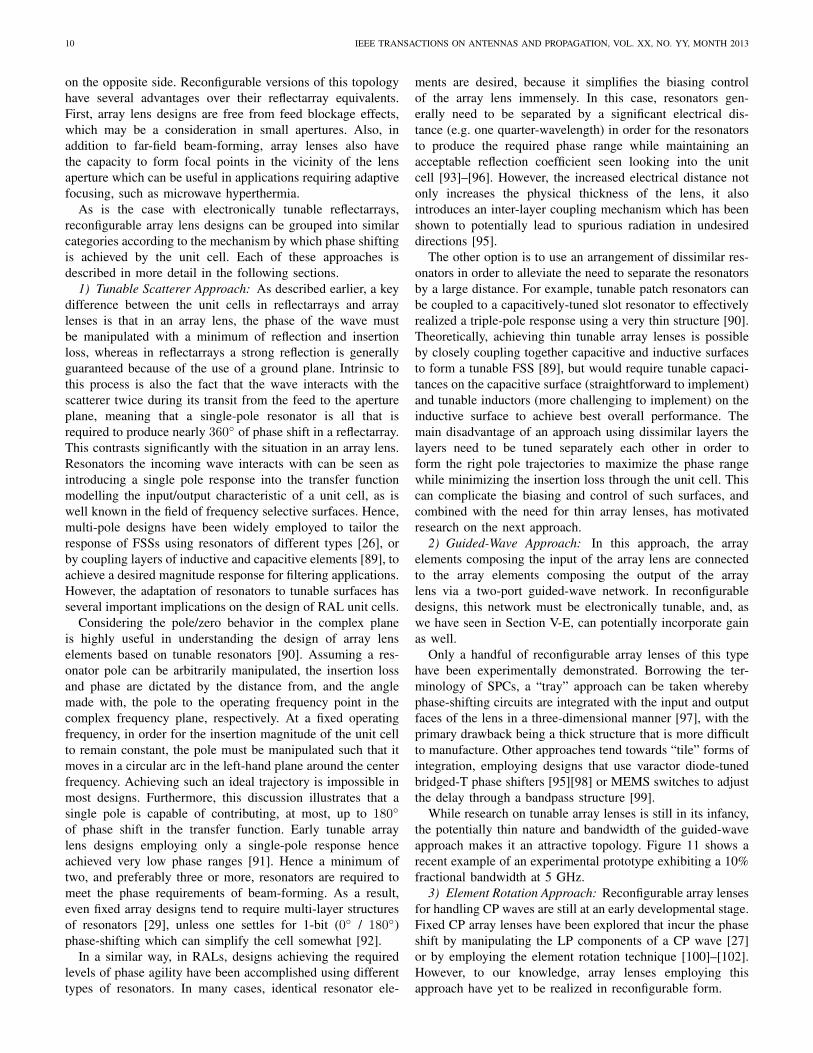
While research on tunable array lenses is still in its infancy,the potentially thin nature and bandwidth of the guided-waveapproach makes it an attractive topology. Figure 11 shows arecent example of an experimental prototype exhibiting a 10%fractional bandwidth at 5 GHz.
3) Element Rotation Approach: Reconfigurable array lensesfor handling CP waves are still at an early developmental stage.Fixed CP array lenses have been explored that incur the phaseshift by manipulating the LP components of a CP wave [27]or by employing the element rotation technique [100]–[102].However, to our knowledge, array lenses employing thisapproach have yet to be realized in reconfigurable form.
RECONFIGURABLE REFLECTARRAYS AND ARRAY LENSES FOR DYNAMIC ANTENNA BEAM CONTROL: A REVIEW 11
Fig. 11. Experimental array lens [95]
VII. ONGOING AND FUTURE CHALLENGES
A. Bandwidth extension and transformation optics approaches
A well-known limitation of reflectarrays and array lenses istheir limited operating bandwidth, and this is currently a veryactive area of research. Bandwidth limitations fundamentallyoriginate from the fact that in order to achieve ideal band-width characteristics, the array elements must produce a truetime delay (TTD) response. Most reflectarray and array lenselements can only approximate such a response over a narrowbandwidth. Addressing this limitation for RRAs and RALs isparticularly challenging, for reasons that are outlined below.
In the case of reflectarrays, bandwidth constraints are usu-ally alleviated by employing one of two approaches. Thefirst is to increase the phase bandwidth of the elements byattempting to approximate the TTD response over a limitedband. This can be achieved by employing multi-resonant ele-ments, such as stacked patches [12] and concentric loops [13]to name a few popular techniques. These approaches havebeen applied with success in fixed reflectarrays, improvingbandwidth from around 3% in the case of single-resonant el-ements to around 12% in the case of multi-resonant elements.The challenge with adapting this to reconfigurable designs isthat these element designs employed coupled resonators toimprove the bandwidth of the element. By varying the sizeand shape of the individual resonators, one not only changesthe resonant frequency of each constituent resonator, but alsothe inter-resonator coupling. In electronically tunable variants,the resonator frequency can be readily controlled throughintegration with tunable components, as we have seen inSection IV-A, but the inter-resonator electromagnetic couplingis not affected significantly by the tuning because the geometryof the resonator remains fixed. Hence, more sophisticatedtuning techniques, that also employing tunable devices tovary the inter-resonator coupling, are required to improve thebandwidth of multi-resonant element designs [103]. Using thistechnique, the element phase bandwidth can be effectivelymultiplied by the number of resonators employed in the unitcell.
Resonators composing the element can also be designed tobe co-planar, which tends to reduce the coupling effect andallow the individual resonances of each element to play alarger role in controlling the bandwidth. Unit cells composedof three parallel dipole resonators situated over a tunable liquidcrystal substrate have been proposed [104] and experimentallyverified [46] as a means for extending the bandwidth of LCcells to 8%.
The desired TTD behavior can be easily achieved usingthe guided-wave approach. Fixed designs employing aperture-coupled microstrip delay lines [105] have been shown tosubstantially improve the bandwidth of reflectarrays to the10% range. As discussed earlier, this approach can be adaptedto provide beam-steering [106]. However, since the amountof time delay that can be created within the space constraintsof the cell is limited, and the bandwidth of such element isalso conditional to the wideband matching of the resonatingelement with the phase shifter.
For array lenses, the bandwidth similarly depends on theirimplementation. Classical array lenses were based on transmis-sion lines connecting the input and output elements. However,array lenses based on resonant FSS structures have smallerbandwidths, though this situation has been alleviated throughthe use of miniaturized element FSSs (MEFSSs) [89].
Similar to reflectarrays, wideband RALs must employ eitherwideband phase shifters coupled to wideband elements, or re-configurable TTD structures. As wideband element and phaseshifter designs are widespread in the literature, ultimatelythe bandwidth limitations stem from issues arising in thecompact integration of the elements with the phase shiftersin the former approach [95]. Regarding the latter approach,again, switched structures, which trade off bit resolution forbandwidth, attempt to implement TTD structures for enhancedbandwidth [99].
Ways to further improve the bandwidth of spatially-fedapertures is an area of active research, with particularlypromising solutions arising from the field of transformationoptics (TO) [107]. In the synthesis of wideband apertures usinga TO approach, the desired field transformation (e.g. froma spherical feed to a plane-wave pencil-beam) is definedspatially in one spatial domain, and the metric-invariant prop-erty of Maxwell’s equations can be employed to achievethe same wave propagation in another spatial domain filledwith a region of inhomogeneous dielectrics. In the case ofreflectarrays, this region is a cover that is placed over a flatreflector (ground plane) composing the reflector, while in arraylenses, the region defines the lens itself. Conceptually, thecase in Figure 12 illustrates the transformation between thewarped space (virtual space) and the regular space (physicalspace) succinctly. Essentially, the material cover implementsa spatially-distributed TTD system to ensure all rays fromthe feed are delayed appropriately by the aperture. Moreover,since the transformation does not yield large zones of materialsexhibiting unusual electromagnetic properties (e.g. a refractiveindex less than 1), the dispersion associated with such materi-als is avoided yielding a potentially very broadband transfor-mation device. This approach has been used to successfullydesign flat reflectors [108] and lenses [109][110] in principle.
Researchers have contemplated beam-steerableversions [111] provided the electromagnetic propertiesof the dielectric region can be manipulated. Effective materialimplementations based on metallic conductors have recentlybeen investigated as a means for realizing the dielectricregion, while providing reflectors with very large potentialbeam-scanning ranges [112]. A similar implementationcan be pursued for array lenses. Such conductors can be

12 IEEE TRANSACTIONS ON ANTENNAS AND PROPAGATION, VOL. XX, NO. YY, MONTH 2013
focal point
(a) Virtual space
TO reflector
T
PEC
focal point
(b) Physical space
Fig. 12. Transformation between virtual (a) and physical spaces (b) in theTO approach
loaded with tunable components to yield ultra-widebandimplementations of spatially-fed apertures, which may benefitmany applications in the future. A disadvantage of thisapproach is that the dielectric region tends to be quite thick inorder to facilitate the field transformation, creating interestingchallenges for future research.
B. Mitigating Nonlinear BehaviorA major challenge facing designers of electronically tunable
reflectarrays and array lenses is the linearity of the underlyingtuning technology. Table I summarizes the technologies andshows their corresponding linearity. RRAs and RALs arebeing proposed for satellite and RADAR applications, whichemploy transmitters with very high output powers. Hence, theillumination of the aperture may induce nonlinear behaviourin the underlying technologies, leading to harmonic and inter-modulation distortion (IMD). In the area of communicationsystems, particularly satellite communications, there are strictlimitations on the allowable adjacent channel interference andharmonic levels produced by the transmitter. Even passiveinter-modulation is a source of compliance failure in thesetransmitters, indicating that ultra-linear tuning technologiesmust be employed should reconfigurable apertures find prac-tical use in these applications.
Semiconductor technologies, while mature and widespread,are the most prone to this problem. Varactor diodes inte-grated in the aperture, for example, can easily have theircapacitance modulated at the frequency of the illuminatingsignal, causing phase modulation that manifests itself in termsof distortion of the scattered signal. For example, the IMDperformance of a single-pole reflectarray element has beenevaluated in a waveguide simulator [36], illustrating that evenunder modest illumination power levels, the creation of odd-order distortion is significant for varactor diode-tuned elementswhich ultimately may relegate such apertures to receive-onlyapplications. Researchers are keenly aware of this and effortsto document the linearity of new designs is undertaken in mostrecent studies [92].
Nevertheless, addressing this challenge remains a funda-mental concern for designers. Ultimately, MEMS technologymay be the solution to this problem [39][113]. Other exoticmaterials possessing large relaxation times, such as liquidcrystals, may also be contenders as the underlying technologiesmature.
C. Very large apertures realized using compound apertures
Realizing very large, high-gain apertures composed of re-configurable unit cells, while theoretically possible, posesmany practical constraints in terms of the number of devicesrequired (and associated cost), bias network complexities, andin some cases, device power requirements. However, manyhigh-gain cost-effective solutions can be realized by combin-ing adaptive spatially-fed arrays with fixed apertures. The mostcommon of these is a parabolic or flat main reflector (whichitself could be realized as a fixed reflectarray) illuminatedby a sub-reflector composed of a reflectarray. Such dual-reflector combinations can be used to emulate their traditionalcounterparts, such as the Cassegrain antennas [114] and offsetreflectors [115]. In particular, employing a reconfigurable sub-reflectarray (or array lens) is an effective way to managethe cost of the antenna system, since the primary large-areaaperture is not reconfigurable. The tradeoff is that the overallscanning range of the antenna system is reduced, often to justa few degrees depending on the system geometry. However,many applications do not require large scan ranges, suchas atmospheric limb-sounding, certain satellite applications,etc. Liquid-crystal reflectarrays have successfully been inte-grated as sub-reflectors into dual-reflector systems for suchpurposes [116], and extensions of this technique to otherconfigurations may be a practical way forward in realizingvery high gain reconfigurable apertures in the future.
D. Towards Terahertz and Optical Frequencies
The application of the reflectarray and lens-array concepts tohigher frequencies has recently attracted significant attention.For instance, at optical frequencies fixed configurations havebeen proposed using metals in the plasmonic regime [117]–[120] and lower-loss dielectric scatterers [121]. Though higheroperation frequencies obviously entail significant novel prac-tical considerations, the operating principle is essentially thesame as in prior art at lower frequencies.
Dynamic beam control is now also considered at higherfrequencies. Potential applications at terahertz frequencies arenumerous both for sensing and communication, where thereflectarray and lens-array concept should provide a low-lossand relatively simple solution for electronic beam control.At optical frequencies, applications mostly relate to sensingbut flexible free-space interconnects or even visible lightcommunication could be of interest in the future.
Early attempts to beam-scanning at particularly high fre-quencies include the on-going effort to produce a MEMS-based reflectarray at 120 GHz [122]. However, such frequen-cies can be considered as an upper bound for the applicabilityof standard RF-MEMS technology, among others, because theMEMS elements become too electrical large to efficiently beintegrated within the array unit cell. Therefore, it is particularlyrelevant to consider enabling technologies based on reconfig-urable materials. For instance, there have been experimentaldemonstrations of reflectarray unit cells using LC crystals,based on the principle that the LC anisotropic permittivitytensor is modified by an applied bias field [46]. Though thisdemonstration was done at sub-millimeter-wave frequencies,

RECONFIGURABLE REFLECTARRAYS AND ARRAY LENSES FOR DYNAMIC ANTENNA BEAM CONTROL: A REVIEW 13
the use of LC has proven very efficient at optical frequenciesin display applications and thus should also be applicable tothe reflectarray concept. Second, the use of graphene for beam-scanning at 1.3 THz has been proposed [47]. In this case,graphene’s 2D complex surface impedance is dynamicallycontrolled by applying a bias voltage to a nearby electrode(so-called graphene ‘field effect’) to achieve dynamic phasecontrol. These LC and graphene cell concepts are based onthe typical resonant cell topology consisting of a conductivepatch resonator above a substrate, with the following notabledifference. In the case of LC it is the substrate parameters thatare controlled, while in the case of graphene the substrate isfixed but the resonance is altered by the change in the complexconductivity of the graphene patch.
These results are encouraging but preliminary in termsof the highest frequency achievable and experimental imple-mentations. Moreover, other enabling technologies should bestudied and compared. Therefore the implementation of beam-scanning RRAs and RALs at terahertz and optical frequenciesconstitute an important and exciting playground, where tech-nological issues are bound to play an extremely important rolecompared to lower frequency applications.
VIII. CONCLUSIONS
Recent progress on reconfigurable reflectarrays and arraylenses is enabling these architectures to compete with estab-lished antenna beam-forming technologies such as phased ar-rays. Essentially, these architectures combine the best featuresof arrays and aperture antennas, yielding an efficient yet cost-effective platform for high-gain adaptive beam-forming andbeam-synthesis. This article has reviewed the key technologiesand approaches for realizing these antennas, and identifiedsome key capabilities of RRAs and RALs provide that areunique to these antenna types and not easily replicated usingother platforms.
Looking forward, this research area is full of excitingfuture research possibilities. This paper has outlined someof the present shortcomings of the technologies in terms ofbandwidth, operating frequency, hardware cost, and linearity,and continued exploration of the underlying technologies anddesigns of RRAs and RALs will make them even morepromising candidates for host of applications in the future.
REFERENCES
[1] D. G. Berry, R. G. Malech, and W. A. Kennedy, “The reflectarrayantenna,” IEEE Trans. Antennas Propag., vol. 11, no. 6, pp. 645–651,Nov. 1963.
[2] J. Huang, “Microstrip reflectarray,” in 1991 Antennas Propag. Soc. Int.Symp. Dig., vol. 2, Jun. 1991, pp. 612–615.
[3] J. Huang and J. A. Encinar, Reflectarray Antennas. Wiley - IEEEPress, 2007.
[4] D. M. Pozar, S. D. Targonski, and H. D. Syrigos, “Design of millimeterwave microstrip reflectarrays,” IEEE Trans. Antennas Propag., vol. 45,no. 2, pp. 287–296, Feb. 1997.
[5] M. R. Chaharmir, J. Shaker, M. Cuhaci, and A. Sebak, “Reflectarraywith variable slots on ground plane,” IEE Proc. Microwaves AntennasPropag., vol. 150, no. 6, pp. 436–439, Dec 2003.
[6] M. Bialkowski and K. H. Sayidmarie, “Investigations into phasecharacteristics of a single-layer reflectarray employing patch or ringelements of variable size,” IEEE Trans. Antennas Propag., vol. 56,no. 11, pp. 3366–3372, 2008.
[7] M. Bozzi, S. Germani, and L. Perregrini, “Performance comparison ofdifferent element shapes used in printed reflectarrays,” IEEE AntennasWireless Propag. Lett., vol. 2, no. 1, pp. 219–222, 2003.
[8] D. C. Chang and M. C. Huang, “Multiple-polarization microstripreflectarray antenna with high efficiency and low cross-polarization,”IEEE Trans. Antennas Propag., vol. 43, no. 8, pp. 829–834, Aug. 1995.
[9] J. Huang and R. J. Pogorzelski, “A Ka-band microstrip reflectarraywith elements having variable rotation angles,” IEEE Trans. AntennasPropag., vol. 46, no. 5, pp. 650–656, May 1998.
[10] A. Martynyuk, J. Martinez Lopez, and N. Martynyuk, “Spiraphase-type reflectarrays based on loaded ring slot resonators,” IEEE Trans.Antennas Propag., vol. 52, no. 1, pp. 142–153, 2004.
[11] J. Encinar, “Design of two-layer printed reflectarrays using patchesof variable size,” IEEE Trans. Antennas Propag., vol. 49, no. 10, pp.1403–1410, Oct. 2001.
[12] J. A. Encinar and J. A. Zornoza, “Broadband design of three-layerprinted reflectarrays,” IEEE Trans. Antennas Propag., vol. 51, no. 7,pp. 1662–1664, Jul. 2003.
[13] M. Chaharmir, J. Shaker, N. Gagnon, and D. Lee, “Design of broad-band, single layer dual-band large reflectarray using multi open loopelements,” IEEE Trans. Antennas Propag., vol. 58, no. 9, pp. 2875–2883, 2010.
[14] E. Carrasco, J. Encinar, and M. Barba, “Bandwidth improvement inlarge reflectarrays by using true-time delay,” IEEE Trans. AntennasPropag., vol. 56, no. 8, pp. 2496–2503, 2008.
[15] S.-H. Hsu, C. Han, J. Huang, and K. Chang, “An offset linear-array-fedku/ka dual-band reflectarray for planet cloud/precipitation radar,” IEEETrans. Antennas Propag., vol. 55, no. 11, pp. 3114–3122, 2007.
[16] A. Yu, F. Yang, A. Elsherbeni, and J. Huang, “Experimental demon-stration of a single layer tri-band circularly polarized reflectarray,” inProc. 2010 IEEE Antennas Propag. Soc. Int. Symp., 2010.
[17] D. Pozar, “Wideband reflectarrays using artificial impedance surfaces,”Electron. Lett., vol. 43, no. 3, pp. 148–149, 2007.
[18] D. Sievenpiper, L. Zhang, R. F. Broas, N. G. Alexopolous, andE. Yablonovitch, “High-impedance electromagnetic surfaces with aforbidden frequency band,” IEEE Trans. Microw. Theory Tech., vol. 47,no. 11, pp. 2059–2074, Nov. 1999.
[19] P. Nayeri, F. Yang, and A. Elsherbeni, “Broadband reflectarray antennasusing double-layer subwavelength patch elements,” IEEE AntennasWireless Propag. Lett., vol. 9, pp. 1139–1142, 2010.
[20] A. Edalati and K. Sarabandi, “Wideband reflectarray antenna basedon miniaturized element frequency selective surfaces,” in Proc. 2012Europ. Conf. Antennas Propag. (EuCAP2012), 2012, pp. 362–364.
[21] W. E. Kock, “Path-length microwave lenses,” Proc. IRE, vol. 37, no. 8,pp. 852–855, 1949.
[22] D. McGrath, “Planar three-dimensional constrained lenses,” IEEETrans. Antennas Propag., vol. 34, no. 1, pp. 46–50, 1986.
[23] D. M. Pozar, “Flat lens antenna concept using aperture coupledmicrostrip patches,” Electron. Lett., vol. 32, no. 23, pp. 2109–2111,1996.
[24] Z. Popovic and A. Mortazawi, “Quasi-optical transmit/receive frontends,” IEEE Trans. Microw. Theory Tech., vol. 46, no. 11, pp. 1964–1975, 1998.
[25] M. Barba, E. Carrasco, and J. A. Encinar, “Suitable planar transmit-arrays in X-band,” in Proc. 2006 Europ. Conf. Antennas Propag.(EuCAP2006), 2006.
[26] A. Abbaspour-Tamijani, K. Sarabandi, and G. M. Rebeiz, “Antenna-filter-antenna arrays as a class of bandpass frequency-selective sur-faces,” IEEE Trans. Microw. Theory Tech., vol. 52, no. 8, pp. 1781–1789, 2004.
[27] R. Phillion and M. Okoniewski, “Lenses for circular polarization usingplanar arrays of rotated passive elements,” IEEE Trans. AntennasPropag., vol. 59, no. 4, pp. 1217 –1227, 2011.
[28] R. Milne, “Dipole array lens antenna,” in Antennas Propag. Soc. Int.Symp., vol. 18, 1980, pp. 576–579.
[29] C. G. M. Ryan, M. R. Chaharmir, J. Shaker, J. R. Bray, Y. M. M. Antar,and A. Ittipiboon, “A wideband transmitarray using dual-resonantdouble square rings,” IEEE Trans. Antennas Propag., vol. 58, no. 5,pp. 1486 –1493, 2010.
[30] M. Al-Joumayly and N. Behdad, “Wideband planar microwave lensesusing sub-wavelength spatial phase shifters,” IEEE Trans. AntennasPropag., vol. 59, no. 12, pp. 4542–4552, 2011.
[31] M. E. Cooley, J. F. Walker, D. G. Gonzalez, and G. E. Pollon, “Novelreflectarray element with variable phase characteristics,” IEE Proc.Microwaves Antennas Propag., vol. 144, no. 2, pp. 149–151, May 1997.

14 IEEE TRANSACTIONS ON ANTENNAS AND PROPAGATION, VOL. XX, NO. YY, MONTH 2013
[32] M. Chaharmir, J. Shaker, M. Cuhaci, and A. Sebak, “Novelphotonically-controlled reflectarray antenna,” IEEE Trans. AntennasPropag., vol. 54, no. 4, pp. 1134–1141, 2006.
[33] H. Legay, D. Bresciani, E. Girard, R. Chiniard, E. Labiole, O. Vendier,and G. Caille, “Recent developments on reflectarray antennas atThales Alenia Space,” in Proc. 2009 Europ. Conf. Antennas Propag.(EuCAP2009), 2009, pp. 2515–2519.
[34] S. Long and G. Huff, “A fluidic loading mechanism for phase recon-figurable reflectarray elements,” IEEE Antennas Wireless Propag. Lett.,vol. 10, pp. 876–879, 2011.
[35] E. Carrasco and J. Perruisseau-Carrier, “Reflectarray antenna at tera-hertz using graphene,” IEEE Antennas Wireless Propag. Lett., vol. 12,pp. 253–256, 2013.
[36] S. V. Hum, M. Okoniewski, and R. J. Davies, “Modeling and designof electronically tunable reflectarrays,” IEEE Trans. Antennas Propag.,vol. 55, no. 8, pp. 2200–2210, Aug. 2007.
[37] H. Kamoda, T. Iwasaki, J. Tsumochi, T. Kuki, and O. Hashimoto,“60-GHz electronically reconfigurable large reflectarray using single-bit phase shifters,” IEEE Trans. Antennas Propag., vol. 59, no. 7, pp.2524–2531, 2011.
[38] H. Legay, B. Pinte, M. Charrier, A. Ziaei, E. Girard, and R. Gillard,“A steerable reflectarray antenna with MEMS controls,” in Proc. 2003IEEE Int. Symp. Phased Array Syst. Tech., 2003, pp. 494–499.
[39] S. V. Hum, G. McFeetors, and M. Okoniewski, “Integrated MEMSreflectarray elements,” in Proc. 2006 Europ. Conf. Antennas Propag.(EuCAP2006), Nov. 2006.
[40] J. Perruisseau-Carrier and A. Skriverviky, “Monolithic MEMS-basedreflectarray cell digitally reconfigurable over a 360◦ phase range,” IEEEAntennas Wireless Propag. Lett., vol. 7, pp. 138–141, 2008.
[41] R. Romanofsky, “Advances in scanning reflectarray antennas based onferroelectric thin-film phase shifters for deep-space communications,”Proc. IEEE, vol. 95, no. 10, pp. 1968–1975, 2007.
[42] R. Mailloux, Phased array antenna handbook. Boston: Artech House,2005.
[43] S. Ebadi, R. Gatti, and R. Sorrentino, “Linear reflectarray antennadesign using 1-bit digital phase shifters,” in Proc. 2009 Europ. Conf.Antennas Propag. (EuCAP2009), 2009, pp. 3729–3732.
[44] T. Debogovic, S. Susac, and J. Perruisseau-Carrier, “A simple re-flectarray cell for 1-bit phase control and polarization flexibility,” inProc. 2013 Europ. Conf. Antennas Propag. (EuCAP2013), Gothenburg,Sweden, 2013.
[45] S. Montori, F. Cacciamani, R. Gatti, E. Carrasco, M. Barba, J. Encinar,and R. Sorrentino, “Wideband dual-polarization reconfigurable elemen-tary cell for electronic steerable reflectarray at Ku-band,” in Proc. 2010Europ. Conf. Antennas Propag. (EuCAP2010), 2010.
[46] G. Perez-Palomino, P. Baine, R. Dickie, M. Bain, J. Encinar, R. Cahill,M. Barba, and G. Toso, “Design and experimental validation ofliquid crystal-based reconfigurable reflectarray elements with improvedbandwidth in F-band,” IEEE Trans. Antennas Propag., vol. 61, no. 4,pp. 1704–1713, 2013.
[47] E. Carrasco, M. Tamagnone, and J. Perruisseau-Carrier, “Tunablegraphene reflective cells for thz reflectarrays and generalized law ofreflection,” Appl. Phys. Lett., vol. 102, no. 10, pp. 104 103–104 103–4,2013.
[48] J. Perruisseau-Carrier, F. Bongard, R. Golubovic-Niciforovic,R. Torres-Sanchez, and J. Mosig, “Contributions to the modeling anddesign of reconfigurable reflecting cells embedding discrete controlelements,” IEEE Trans. Microw. Theory Tech., vol. 58, no. 6, pp.1621–1628, 2010.
[49] J. Perruisseau-Carrier, E. Girard, and H. Legay, “Analysis of a recon-figurable reflectarray cell comprising a multitude of MEMS controlelements,” in Proc. 2010 Europ. Conf. Antennas Propag. (EuCAP2010),2010.
[50] H. Salti, E. Fourn, R. Gillard, and H. Legay, “Minimization of MEMSbreakdowns effects on the radiation of a MEMS based reconfigurablereflectarray,” IEEE Trans. Antennas Propag., vol. 58, no. 7, pp. 2281–2287, 2010.
[51] M. Yousefbeiki and J. Perruisseau-Carrier, “A practical technique foraccurately modeling reconfigurable lumped components in commercialfull-wave solvers [EurAAP corner],” IEEE Antennas Propag. Mag.,vol. 54, no. 5, pp. 298–303, 2012.
[52] S. Hum, M. Okoniewski, and R. Davies, “Realizing an electronicallytunable reflectarray using varactor diode-tuned elements,” IEEE Mi-crow. Wireless Compon. Lett., vol. 15, no. 6, pp. 422–424, 2005.
[53] M. Riel and J. Laurin, “Design of an electronically beam scanningreflectarray using aperture-coupled elements,” IEEE Trans. AntennasPropag., vol. 55, no. 5, pp. 1260–1266, 2007.
[54] J. Rodriguez-Zamudio, J. Martinez-Lopez, J. Rodriguez-Cuevas, andA. Martynyuk, “Reconfigurable reflectarrays based on optimizedspiraphase-type elements,” IEEE Trans. Antennas Propag., vol. 60,no. 4, pp. 1821–1830, 2012.
[55] P. Bhartia and I. J. Bahl, “Frequency agile microstrip antennas,”Microwave Journal, pp. 67–70, Oct. 1982.
[56] L. Boccia, F. Venneri, G. Amendola, and G. Di Massa, “Application ofvaractor diodes for reflectarray phase control,” in Proc. 2002 AntennasPropag. Soc. Int. Symp., vol. 3, Jun. 2002, pp. 132–135.
[57] O. Vendik and M. Parnes, “A phase shifter with one tunable componentfor a reflectarray antenna,” IEEE Antennas Propag. Mag., vol. 50, no. 4,pp. 53–65, 2008.
[58] L. Boccia, G. Amendola, and G. Di Massa, “Performance improvementfor a varactor-loaded reflectarray element,” IEEE Trans. AntennasPropag., vol. 58, no. 2, pp. 585–589, 2010.
[59] H. Legay, Y. Cailloce, O. Vendier, G. Caille, J. Perruisseau-Carrier,M. Lathi, J. Polizzi, U. Oestermann, P. Pons, and N. Raveu, “Satelliteantennas based on MEMS tunable reflectarrays,” in Proc. 2007 Europ.Conf. Antennas Propag. (EuCAP2007), 2007.
[60] H. Rajagopalan, Y. Rahmat-Samii, and W. Imbriale, “RF MEMSactuated reconfigurable reflectarray patch-slot element,” IEEE Trans.Antennas Propag., vol. 56, no. 12, pp. 3689–3699, 2008.
[61] H. Aubert, N. Raveu, E. Perret, and H. Legay, “Multi-scale approachfor the electromagnetic modelling of MEMS-controlled reflectarrays,”in Proc. 2006 Europ. Conf. Antennas Propag. (EuCAP2006), 2006.
[62] A. Moessinger, R. Marin, S. Mueller, J. Freese, and R. Jakoby, “Elec-tronically reconfigurable reflectarrays with nematic liquid crystals,”Electron. Lett., vol. 42, no. 16, pp. 899–900, 3, 2006.
[63] W. Hu, R. Cahill, J. Encinar, R. Dickie, H. Gamble, V. Fusco, andN. Grant, “Design and measurement of reconfigurable millimeter wavereflectarray cells with nematic liquid crystal,” IEEE Trans. AntennasPropag., vol. 56, no. 10, pp. 3112–3117, 2008.
[64] R. Romanofsky, J. Bernhard, F. Van Keuls, F. Miranda, G. Wash-ington, and C. Canedy, “K-band phased array antennas based onBa0.60Sr0.40TiO3 thin-film phase shifters,” IEEE Trans. Microw. The-ory Tech., vol. 48, no. 12, pp. 2504–2510, 2000.
[65] M. Sazegar, A. Giere, Y. Zheng, H. Maune, A. Moessinger, andR. Jakoby, “Reconfigurable unit cell for reflectarray antenna basedon barium-strontium-titanate thick-film ceramic,” in 2009 Europ. Mi-crowave Conf. (EuMC 2009), 2009, pp. 598–601.
[66] B. A. Munk, Frequency Selective Surfaces: Theory and Design. NewYork: Wiley-Interscience, 2000.
[67] K. Karnati, Y. Yusuf, S. Ebadi, and X. Gong, “Theoretical analysison reflection properties of reflectarray unit cells using quality factors,”IEEE Trans. Antennas Propag., vol. 61, no. 1, pp. 201–210, 2013.
[68] D. Sievenpiper, J. Schaffner, R. Loo, G. Tangonan, S. Ontiveros, andR. Harold, “A tunable impedance surface performing as a reconfig-urable beam steering reflector,” IEEE Trans. Antennas Propag., vol. 50,no. 3, pp. 384–390, Mar. 2002.
[69] E. Carrasco, M. Barba, and J. Encinar, “X-band reflectarray antennawith switching-beam using pin diodes and gathered elements,” IEEETrans. Antennas Propag., vol. 60, no. 12, pp. 5700–5708, 2012.
[70] T. Debogovic, J. Perruisseau-Carrier, and J. Bartolic, “Partially reflec-tive surface antenna with dynamic beamwidth control,” IEEE AntennasWireless Propag. Lett., vol. 9, pp. 1157–1160, 2010.
[71] O. Bayraktar, O. Civi, and T. Akin, “Beam switching reflectarray mono-lithically integrated with rf mems switches,” IEEE Trans. AntennasPropag., vol. 60, no. 2, pp. 854–862, 2012.
[72] E. Carrasco, M. Barba, B. Reig, C. Dieppedale, and J. Encinar,“Characterization of a reflectarray gathered element with electroniccontrol using ohmic RF MEMS and patches aperture-coupled to a delayline,” IEEE Trans. Antennas Propag., vol. 60, no. 9, pp. 4190–4201,2012.
[73] H. R. Phelan, “Spiraphase reflectarray for multitarget radar,” Mi-crowave Journal, vol. 20, p. 67, Jul. 1977.
[74] C. Guclu, J. Perruisseau-Carrier, and O. Civi, “Proof of concept of adual-band circularly-polarized RF MEMS beam-switching reflectarray,”IEEE Trans. Antennas Propag., vol. 60, no. 11, pp. 5451–5455, 2012.
[75] R. Phillion and M. Okoniewski, “Improving the phase resolution ofa micromotor-actuated phased reflectarray,” in 2008 Microsystems andNanoelectronics Research Conference (MNRC 2008), 2008, pp. 169–172.
[76] J. Perruisseau-Carrier, “Versatile reconfiguration of radiation patterns,frequency and polarization: A discussion on the potential of control-lable reflectarrays for software-defined and cognitive radio systems,”in 2010 IEEE International Microwave Workshop Series on RF Front-

RECONFIGURABLE REFLECTARRAYS AND ARRAY LENSES FOR DYNAMIC ANTENNA BEAM CONTROL: A REVIEW 15
ends for Software Defined and Cognitive Radio Solutions (IMWS),,2010.
[77] J. Perruisseau-Carrier and P. Pardo, “Unit cells for dual-polarized andpolarization-flexible reflectarrays with scanning capabilities,” in Proc.2009 Europ. Conf. Antennas Propag. (EuCAP2009), 2009, pp. 1218–1221.
[78] J. Perruisseau-Carrier, “Dual-polarized and polarization-flexible reflec-tive cells with dynamic phase control,” IEEE Trans. Antennas Propag.,vol. 58, no. 5, pp. 1494–1502, 2010.
[79] E. Carrasco, J. Encinar, M. Barba, R. Vincenti, and R. Sorrentino,“Dual-polarization reflectarray elements for ku-band tx/rx portableterminal antenna,” in Proc. 2010 Europ. Conf. Antennas Propag.(EuCAP2010), 2010.
[80] E. Carrasco, B. Mariano, J. A. Encinar, and J. Perruisseau-Carrier,“Two-bit reflectarray elements with phase and polarization reconfigu-ration (accepted),” in Proc. 2013 IEEE Int. Symp. Antennas Propag.,Orlando, Florida, 2013.
[81] S. Mener, R. Gillard, R. Sauleau, C. Cheymol, and P. Potier, “Designand characterization of a CPSS-based unit-cell for circularly polarizedreflectarray applications,” IEEE Trans. Antennas Propag., vol. 61, no. 4,pp. 2313–2318, 2013.
[82] D. Rodrigo, L. Jofre, and J. Perruisseau-Carrier, “A frequency reconfig-urable cell for beam-scanning reflectarrays (accepted),” in Proc. 2013IEEE Int. Symp. Antennas Propag., Orlando, Florida, 2013.
[83] J. A. Navarro and K. Chang, Integrated Active Antennas and SpatialPower Combining. John Wiley & Sons, 1996.
[84] K. Kishor and S. Hum, “An amplifying reconfigurable reflectarrayantenna,” IEEE Trans. Antennas Propag., vol. 60, no. 1, pp. 197–205,2012.
[85] M. E. Bialkowski, A. W. Robinson, and H. J. Song, “Design, devel-opment, and testing of X-band amplifying reflectarrays,” IEEE Trans.Antennas Propag., vol. 50, no. 8, pp. 1065–1076, Aug. 2002.
[86] R. W. Clark, G. H. Huff, and J. T. Bernhard, “An integrated activemicrostrip reflectarray element with an internal amplifier,” IEEE Trans.Antennas Propag., vol. 51, no. 5, pp. 993–999, May 2003.
[87] Lorena Cabria, Jose Angel Garcıa, Julio Gutierrez-Rıos, AntonioTazon, and Juan Vassal’lo, “Active reflectors possible solutions basedon reflectarrays and fresnel reflectors,” Int. Jour. Antennas Propag., vol.2009, Article ID 653952, 13 pages, 2009.
[88] G. Ruggerini, G. Toso, and P. Angeletti, “A discrete aperiodic activelens for multibeam satellite applications,” in 2010 IEEE InternationalSymposium on Phased Array Systems and Technology (ARRAY), 2010,pp. 524–528.
[89] M. A. Al-Joumayly and N. Behdad, “A generalized method forsynthesizing low-profile, band-pass frequency selective surfaces withnon-resonant constituting elements,” IEEE Trans. Antennas Propag.,vol. 58, no. 12, pp. 4033 –4041, 2010.
[90] J. Lau and S. Hum, “Analysis and characterization of a multipolereconfigurable transmitarray element,” IEEE Trans. Antennas Propag.,vol. 59, no. 1, pp. 70–79, 2011.
[91] P. de la Torre and M. Sierra-Castaner, “Electronically reconfigurablepatches for transmit-array structures at 12 GHz,” in Proc. 2008 IEEEAntennas Propag. Soc. Int. Symp., 2008.
[92] A. Clemente, L. Dussopt, R. Sauleau, P. Potier, and P. Pouliguen, “1-bit reconfigurable unit cell based on PIN diodes for transmit-arrayapplications in -band,” IEEE Trans. Antennas Propag., vol. 60, no. 5,pp. 2260–2269, 2012.
[93] A. Iturri-Hinojosa, J. Martinez-Lopez, and A. Martynyuk, “Analysisand design of E-plane scanning grid arrays,” IEEE Trans. AntennasPropag., vol. 58, no. 7, pp. 2266 –2274, Jul. 2010.
[94] L. Boccia, I. Russo, G. Amendola, and G. Di Massa, “Preliminary re-sults on tunable frequency selective surface for beam steering transmit-array applications,” in Proc. 2011 Europ. Conf. Antennas Propag.(EuCAP2011), 2011, pp. 1002–1005.
[95] J. Y. Lau and S. V. Hum, “A wideband reconfigurable transmitarrayelement,” IEEE Trans. Antennas Propag., vol. 60, no. 3, 2012.
[96] T. Jiang, Z. Wang, D. Li, J. Pan, B. Zhang, J. Huangfu, Y. Salamin,C. Li, and L. Ran, “Low-DC voltage-controlled steering-antennaradome utilizing tunable active metamaterial,” IEEE Trans. Microw.Theory Tech., vol. 60, no. 1, pp. 170–178, 2012.
[97] P. Padilla, A. Munoz-Acevedo, M. Sierra-Castaner, and M. Sierra-Perez, “Electronically reconfigurable transmitarray at Ku band formicrowave applications,” IEEE Trans. Antennas Propag., vol. 58, no. 8,pp. 2571–2579, 2010.
[98] J. Lau and S. Hum, “A wideband reconfigurable transmitarray element,”IEEE Trans. Antennas Propag., vol. 60, no. 3, pp. 1303–1311, 2012.
[99] C.-C. Cheng, B. Lakshminarayanan, and A. Abbaspour-Tamijani,“A programmable lens-array antenna with monolithically integratedMEMS switches,” IEEE Trans. Microw. Theory Tech., vol. 57, no. 8,pp. 1874–1884, Aug. 2009.
[100] S. O’Kane and V. Fusco, “Circularly polarized curl antenna lens withmanual tilt properties,” IEEE Trans. Antennas Propag., vol. 57, no. 12,pp. 3984–3987, 2009.
[101] M. Euler and V. Fusco, “Frequency selective surface using nested splitring slot elements as a lens with mechanically reconfigurable beamsteering capability,” IEEE Trans. Antennas Propag., vol. 58, no. 10,pp. 3417–3421, 2010.
[102] H. Kaouach, L. Dussopt, J. Lanteri, T. Koleck, and R. Sauleau,“Wideband low-loss linear and circular polarization transmit-arrays inv-band,” IEEE Trans. Antennas Propag., vol. 59, no. 7, pp. 2513–2523,2011.
[103] C. Liu and S. Hum, “An electronically tunable single-layer reflectarrayantenna element with improved bandwidth,” IEEE Antennas WirelessPropag. Lett., vol. 9, pp. 1241–1244, 2010.
[104] G. Perez-Palomino, J. Encinar, M. Barba, and E. Carrasco, “Designand evaluation of multi-resonant unit cells based on liquid crystals forreconfigurable reflectarrays,” IEE Proc. Microwaves Antennas Propag.,vol. 6, no. 3, pp. 348–354, 2012.
[105] E. Carrasco, M. Barba, and J. Encinar, “Reflectarray element based onaperture-coupled patches with slots and lines of variable length,” IEEETrans. Antennas Propag., vol. 55, no. 3, pp. 820–825, 2007.
[106] ——, “Design and validation of gathered elements for steerable-beamreflectarrays based on patches aperture-coupled to delay lines,” IEEETrans. Antennas Propag., vol. 59, no. 5, pp. 1756–1761, 2011.
[107] N. Kundtz, D. Smith, and J. Pendry, “Electromagnetic design withtransformation optics,” Proc. IEEE, vol. 99, no. 10, pp. 1622–1633,2011.
[108] W. Tang, C. Argyropoulos, E. Kallos, W. Song, and Y. Hao, “Discretecoordinate transformation for designing all-dielectric flat antennas,”IEEE Trans. Antennas Propag., vol. 58, no. 12, pp. 3795–3804, 2010.
[109] R. Yang, W. Tang, and Y. Hao, “A broadband zone plate lens fromtransformation optics,” Opt. Express, vol. 19, no. 13, pp. 12 348–12 355,Jun 2011.
[110] Q. Wu, J. Turpin, and D. Werner, “Quasi-conformal transformationelectromagnetics enabled flat collimating lenses,” in Proc. 2012 IEEEAntennas Propag. Soc. Int. Symp., 2012.
[111] R. Yang, W. Tang, and Y. Hao, “Wideband beam-steerable flat reflectorsvia transformation optics,” IEEE Antennas Wireless Propag. Lett.,vol. 10, pp. 1290–1294, 2011.
[112] L. Liang and S. V. Hum, “Wide-angle scannable reflector design usingconformal transformation optics,” Opt. Express, vol. 21, no. 2, pp.2133–2146, Jan. 2013.
[113] R. Sorrentino, R. Gatti, and L. Marcaccioli, “Recent advances onmillimetre wave reconfigurable reflectarrays,” in Proc. 2009 Europ.Conf. Antennas Propag. (EuCAP2009), 2009, pp. 2527–2531.
[114] H. Rajagopalan, S. Xu, and Y. Rahmat-Samii, “Reflector antennadistortion compensation using sub-reflectarrays: Simulations and ex-perimental demonstration [AMTA corner],” IEEE Antennas Propag.Mag., vol. 54, no. 3, pp. 235–246, 2012.
[115] C. Tienda, M. Arrebola, J. Encinar, and G. Toso, “Analysis of a dual-reflect array antenna,” IEE Proc. Microwaves Antennas Propag., vol. 5,no. 13, pp. 1636–1645, 2011.
[116] W. Hu, M. Arrebola, R. Cahill, J. Encinar, V. Fusco, H. Gamble,Y. Alvarez, and F. Las-Heras, “94 GHz dual-reflector antenna withreflectarray subreflector,” IEEE Trans. Antennas Propag., vol. 57,no. 10, pp. 3043–3050, 2009.
[117] M. Farmahini-Farahani and H. Mosallaei, “Birefringent reflectarraymetasurface for beam engineering in infrared,” Opt. Lett., vol. 38, no. 4,pp. 462–464, Feb 2013.
[118] T. Niu, W. Withayachumnankul, B. S.-Y. Ung, H. Menekse,M. Bhaskaran, S. Sriram, and C. Fumeaux, “Experimental demonstra-tion of reflectarray antennas at terahertz frequencies,” Opt. Express,vol. 21, no. 3, pp. 2875–2889, Feb 2013.
[119] X. Chen, L. Huang, H. Muhlenbernd, G. Li, B. Bai, Q. Tan, G. Jin, C.-W. Qiu, S. Zhang, and T. Zentgraf, “Dual-polarity plasmonic metalensfor visible light,” Nat. Commun., vol. 3, p. 1198, 11 2012.
[120] N. Yu, N. Yu, P. Genevet, M. A. Kats, and F. Aieta, “Light propa-gation with phase discontinuities: Generalized laws of reflection andrefraction,” Science, vol. 334, no. 6054, pp. 333–337, 10 2011.
[121] L. Zou, W. Withayachumnankul, C. M. Shah, A. Mitchell,M. Bhaskaran, S. Sriram, and C. Fumeaux, “Dielectric resonatornanoantennas at visible frequencies,” Opt. Express, vol. 21, no. 1, pp.1344–1352, Jan. 2013.

16 IEEE TRANSACTIONS ON ANTENNAS AND PROPAGATION, VOL. XX, NO. YY, MONTH 2013
[122] A. Tamminen, J. Ala-Laurinaho, D. Gomes-Martins, J. Hakli,P. Koivisto, M. Karkkainen, S. Makela, P. Pursula, P. Rantakari,M. Sipila, J. Saily, R. Tuovinen, M. Varonen, K. A. I. Halonen,A. Luukanen, and A. V. Raisanen, “Reflectarray for 120-GHz beamsteering application: design, simulations, and measurements,” in Proc.SPIE 8362, Passive and Active Millimeter-Wave Imaging XV, May2012, pp. 836 205–836 205.


![New Multilayer Antennas for Directive Beam Steering Broadside …individual.utoronto.ca/spodilchak/C15.pdf · 2011. 1. 5. · antenna sources [5]-[8] for pencil beam radiation, broadside](https://static.fdocuments.net/doc/165x107/607061204f498773ca09d08a/new-multilayer-antennas-for-directive-beam-steering-broadside-2011-1-5-antenna.jpg)