IEEE Standarts Part 11: Wireless LAN Medium Access Control (MAC) and Physical Layer (PHY)...
78
IEEE Std 802.11g™-2003 (Amendment to IEEE Std 802.11™, 1999 Edition (Reaff 2003) as amended by IEEE Stds 802.11a™ -1999, 802.11b ™ -1999, 802.11b ™ -1999/Cor 1-2001, and 802.11d ™ -2001) IEEE Standards 802.11g TM IEEE Standard for Information technology— Telecommunications and information exchange between systems— Local and metropolitan area networks— Specific requirements Part 11: Wireless LAN Medium Access Control (MAC) and Physical Layer (PHY) specifications Amendment 4: Further Higher Data Rate Extension in the 2.4 GHz Band Published by The Institute of Electrical and Electronics Engineers, Inc. 3 Park Avenue, New York, NY 10016-5997, USA 27 June 2003 IEEE Computer Society Sponsored by the LAN/MAN Standards Committee IEEE Standards Print: SH95134 PDF: SS95134 This amendment is an approved IEEE Standard. It will be incorporated into the base standard in a future edition.
Transcript of IEEE Standarts Part 11: Wireless LAN Medium Access Control (MAC) and Physical Layer (PHY)...
IEEE Std 802.11g™-2003(Amendment to IEEE Std 802.11™, 1999 Edition (Reaff 2003)
as amended byIEEE Stds 802.11a™-1999, 802.11b™-1999,
802.11b™-1999/Cor 1-2001, and 802.11d™-2001)IE
EE
Sta
nd
ard
s 802.11gTM
IEEE Standard for Information technology—
Telecommunications and informationexchange between systems—
Local and metropolitan area networks—
Specific requirements
Part 11: Wireless LAN Medium Access Control(MAC) and Physical Layer (PHY) specifications
Amendment 4: Further Higher Data Rate Extensionin the 2.4 GHz Band
Published by The Institute of Electrical and Electronics Engineers, Inc.3 Park Avenue, New York, NY 10016-5997, USA
27 June 2003
IEEE Computer Society
Sponsored by theLAN/MAN Standards Committee
IEE
E S
tan
dar
ds
Print: SH95134PDF: SS95134
This amendment is an approved IEEEStandard. It will be incorporated into thebase standard in a future edition.
The Institute of Electrical and Electronics Engineers, Inc.3 Park Avenue, New York, NY 10016-5997, USA
Copyright © 2003 by the Institute of Electrical and Electronics Engineers, Inc.All rights reserved. Published 25 June 2003. Printed in the United States of America.
IEEE and 802 are registered trademarks in the U.S. Patent & Trademark Office, owned by the Institute of Electrical and Electronics Engineers, Incorporated.
Print: ISBN 0-7381-3700-6 SH95134PDF: ISBN 0-7381-3701-4 SS95134
No part of this publication may be reproduced in any form, in an electronic retrieval system or otherwise, without the prior written permission of the publisher.
IEEE Std 802.11g�-2003[Amendment to IEEE Std 802.11TM, 1999 Edition (Reaff 2003)
as amended byIEEE Stds 802.11aTM-1999, 802.11bTM-1999,
802.11bTM-1999/Cor 1-2001, and 802.11dTM-2001]
IEEE Standard forInformation technology�Telecommunications and information exchange
between systems�Local and metropolitan area networks�Specific requirements
Part 11: Wireless LAN Medium Access Control (MAC) and Physical Layer (PHY) specificationsAmendment 4: Further Higher Data Rate Extension in the 2.4 GHz BandSponsor
LAN/MAN Standards Committee of theIEEE Computer Society
Approved 12 June 2003
IEEE-SA Standards Board
Abstract: Changes and additions to IEEE Std 802.11, 1999 Edition, as amended by IEEE Stds802.11a-1999, 802.11b-1999, 802.11b-1999/Cor 1-2001, and 802.11d-2001, are provided to sup-port the further higher data rate extension for operation in the 2.4 GHz band.
Keywords: LAN, local area network, radio frequency, wireless

IEEE Standards documents are developed within the IEEE Societies and the Standards Coordinating Committees of the IEEE Stan-dards Association (IEEE-SA) Standards Board. The IEEE develops its standards through a consensus development process, approvedby the American National Standards Institute, which brings together volunteers representing varied viewpoints and interests to achievethe final product. Volunteers are not necessarily members of the Institute and serve without compensation. While the IEEE administersthe process and establishes rules to promote fairness in the consensus development process, the IEEE does not independently evaluate,test, or verify the accuracy of any of the information contained in its standards.
Use of an IEEE Standard is wholly voluntary. The IEEE disclaims liability for any personal injury, property or other damage, of anynature whatsoever, whether special, indirect, consequential, or compensatory, directly or indirectly resulting from the publication, useof, or reliance upon this, or any other IEEE Standard document.
The IEEE does not warrant or represent the accuracy or content of the material contained herein, and expressly disclaims any express orimplied warranty, including any implied warranty of merchantability or fitness for a specific purpose, or that the use of the materialcontained herein is free from patent infringement. IEEE Standards documents are supplied �AS IS.�
The existence of an IEEE Standard does not imply that there are no other ways to produce, test, measure, purchase, market, or provideother goods and services related to the scope of the IEEE Standard. Furthermore, the viewpoint expressed at the time a standard isapproved and issued is subject to change brought about through developments in the state of the art and comments received from usersof the standard. Every IEEE Standard is subjected to review at least every five years for revision or reaffirmation. When a document ismore than five years old and has not been reaffirmed, it is reasonable to conclude that its contents, although still of some value, do notwholly reflect the present state of the art. Users are cautioned to check to determine that they have the latest edition of any IEEE Stan-dard.
In publishing and making this document available, the IEEE is not suggesting or rendering professional or other services for, or onbehalf of, any person or entity. Nor is the IEEE undertaking to perform any duty owed by any other person or entity to another. Any per-son utilizing this, and any other IEEE Standards document, should rely upon the advice of a competent professional in determining theexercise of reasonable care in any given circumstances.
Interpretations: Occasionally questions may arise regarding the meaning of portions of standards as they relate to specific applications.When the need for interpretations is brought to the attention of IEEE, the Institute will initiate action to prepare appropriate responses.Since IEEE Standards represent a consensus of concerned interests, it is important to ensure that any interpretation has also received theconcurrence of a balance of interests. For this reason, IEEE and the members of its societies and Standards Coordinating Committeesare not able to provide an instant response to interpretation requests except in those cases where the matter has previously received for-mal consideration.
Comments for revision of IEEE Standards are welcome from any interested party, regardless of membership affiliation with IEEE. Sug-gestions for changes in documents should be in the form of a proposed change of text, together with appropriate supporting comments.Comments on standards and requests for interpretations should be addressed to:
Secretary, IEEE-SA Standards Board445 Hoes LaneP.O. Box 1331Piscataway, NJ 08855-1331USA
Authorization to photocopy portions of any individual standard for internal or personal use is granted by the Institute of Electrical andElectronics Engineers, Inc., provided that the appropriate fee is paid to Copyright Clearance Center. To arrange for payment of licensingfee, please contact Copyright Clearance Center, Customer Service, 222 Rosewood Drive, Danvers, MA 01923 USA; +1 978 750 8400.Permission to photocopy portions of any individual standard for educational classroom use can also be obtained through the CopyrightClearance Center.
Note: Attention is called to the possibility that implementation of this standard may require use of subject matter coveredby patent rights. By publication of this standard, no position is taken with respect to the existence or validity of any patentrights in connection therewith. The IEEE shall not be responsible for identifying patents for which a license may berequired by an IEEE standard or for conducting inquiries into the legal validity or scope of those patents that are broughtto its attention. A patent holder has filed a statement of assurance that it will grant licenses under these rights without com-pensation or under reasonable rates and nondiscriminatory, reasonable terms and conditions to all applicants desiring toobtain such licenses. The IEEE makes no representation as to the reasonableness of rates and/or terms and conditions ofthe license agreements offered by patent holders. Further information may be obtained from the IEEE StandardsDepartment.
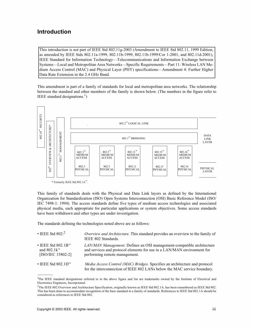
Introduction
This amendment is part of a family of standards for local and metropolitan area networks. The relationshipbetween the standard and other members of the family is shown below. (The numbers in the figure refer toIEEE standard designations.1)
This family of standards deals with the Physical and Data Link layers as defined by the InternationalOrganization for Standardization (ISO) Open Systems Interconnection (OSI) Basic Reference Model (ISO/IEC 7498-1: 1994). The access standards define five types of medium access technologies and associatedphysical media, each appropriate for particular applications or system objectives. Some access standardshave been withdrawn and other types are under investigation.
The standards defining the technologies noted above are as follows:
� IEEE Std 802:2 Overview and Architecture. This standard provides an overview to the family of IEEE 802 Standards.
� IEEE Std 802.1B� LAN/MAN Management. Defines an OSI management-compatible architectureand 802.1k� and services and protocol elements for use in a LAN/MAN environment for [ISO/IEC 15802-2] performing remote management.
� IEEE Std 802.1D� Media Access Control (MAC) Bridges. Specifies an architecture and protocol for the interconnection of IEEE 802 LANs below the MAC service boundary.
1The IEEE standard designations referred to in the above figure and list are trademarks owned by the Institute of Electrical andElectronics Engineers, Incorporated.2The IEEE 802 Overview and Architecture Specification, originally known as IEEE Std 802.1A, has been renumbered as IEEE Std 802.This has been done to accommodate recognition of the base standard in a family of standards. References to IEEE Std 802.1A should beconsidered as references to IEEE Std 802.
This introduction is not part of IEEE Std 802.11g-2003 (Amendment to IEEE Std 802.11, 1999 Edition,as amended by IEEE Stds 802.11a-1999, 802.11b-1999, 802.11b-1999/Cor 1-2001, and 802.11d-2001),IEEE Standard for Information Technology�Telecommunications and Information Exchange betweenSystems�Local and Metropolitan Area Networks�Specific Requirements�Part 11: Wireless LAN Me-dium Access Control (MAC) and Physical Layer (PHY) specifications�Amendment 4: Further HigherData Rate Extension in the 2.4 GHz Band.
* Formerly IEEE Std 802.1A.
DATALINK
LAYER
PHYSICAL
802.2 LOGICAL LINK
802.1 BRIDGING
802.
1 M
AN
AG
EMEN
T
802
OV
ERV
IEW
& A
RCH
ITEC
TURE
*
802.
10
SEC
UR
ITY
802.3MEDIUMACCESS
.
802.3PHYSICAL
802.5MEDIUMACCESS
802.5PHYSICAL
802.11MEDIUMACCESS
802.11PHYSICAL
LAYER
802.16MEDIUMACCESS
802.16PHYSICAL
802.15MEDIUMACCESS
802.15PHYSICAL
Copyright © 2003 IEEE. All rights reserved. iii

� IEEE Std 802.1E� System Load Protocol. Specifies a set of services and protocol for those aspects[ISO/IEC 15802-4] those aspects of management concerned with the loading of systems on IEEE
802 LANs.
� IEEE Std 802.1F� Common Definitions and Procedures for IEEE 802 Management Information.
� IEEE Std 802.1G� Remote Media Access Control (MAC) Bridging. Specifies extensions for the[ISO/IEC 15802-5]: interconnection, using non-LAN systems communication technologies, of
geographically separated IEEE 802 LANs below the level of the logical link control protocol.
� IEEE Std 802.1H� Recommended Practice for Media Access Control (MAC) Bridging of Ethernet [ISO/IEC TR 11802-5] V2.0 in IEEE 802 Local Area Networks.
� IEEE Std 802.1Q� Virtual Bridged Local Area Networks. Defines an architecture for Virtual Bridged LANs, the services provided in Virtual Bridged LANs, and the proto-cols and algorithms involved in the provision of those services.
� IEEE Std 802.2 Logical Link Control.[ISO/IEC 8802-2]
� IEEE Std 802.3 CSMA/CD Access Method and Physical Layer Specifications.
� IEEE Std 802.5 Token Ring Access Method and Physical Layer Specifications.[ISO/IEC 8802-5]
� IEEE Std 802.10 Standard for Interoperable LAN Security (SILS). Currently approved: Secure Data Exchange (SDE).
� IEEE Std 802.11 Wireless LAN Medium Access Control (MAC) Sublayer and Physical Layer[ISO/IEC 8802-11] Specifications.
� IEEE Std 802.15 Wireless Medium Access Control (MAC) and Physical Layer (PHY)Specifications for: Wireless Personal Area Networks.
� IEEE Std 802.16 Air Interface for Fixed Broadband Wireless Access Systems.
The reader of this standard is urged to become familiar with the complete family of standards.
iv Copyright © 2003 IEEE. All rights reserved.
Participants
When the IEEE 802.11 Working Group approved this standard, it had the following membership:
Stuart J. Kerry, ChairAl Petrick and Harry Worstell, Vice-Chairs
Tim Godfrey, SecretaryBrian Mathews, Publicity Standing Committee
Teik-Kheong Tan, Wireless Next-Generation Standing Committee
John Fakatselis, Chair Task Group eDuncan Kitchin, Vice-Chair Task Group e
David Bagby, Chair Task Group fMika Kasslin, Chair Task Group hDavid Halasz, Chair Task Group i
When the IEEE 802.11 Working Group approved this standard, the Task Group G had the followingmembership:
Matthew B. Shoemake, ChairJohn Terry, Vice-Chair
Carl F. Andren, Technical EditorKevin Smart, Secretary
Tomoko AdachiAreg AlimianRichard AllenKeith AmannMerwyn AndradeButch AntonMitch AramakiTakashi AramakiLarry ArnettGeert A. AwaterFloyd BackesDavid BagbyJay BainDennis J. BakerBala BalachanderRaja BanerjeaBoyd BangerterSimon BarberGil Bar-NoyJohn BarrKevin M. BarryAnuj BatraTomer BentzionMathilde BenvenisteSimon BlackJan BoerJim BrennanRonald BrockmannAlistair G. ButtarNancy Cam-WingetBill CarneyPat CarsonClint ChaplinHung-Kun ChenYi-Ming ChenGreg ChessonAlan ChickinskyAik ChindapolLeigh M. Chinitz
Bong-Rak ChoiSunghyun ChoiKen ClementsJohn T. CoffeyTerry ColePaul CongdonCraig ConklingTodor CooklevThomas P. CostasWm. Caldwell CrosswyPeter DahlBarry DavisRolf De VegtJavier del PradoMichael DerbyGeorg DickmannWim DiepstratenRoger DurandEryk DutkiewiczMary DuValDonald E. Eastlake IIIDennis EatonPeter EcclesineJon EdneyChristoph EuscherJohn FakatselisLars FalkAugustin J. FarrugiaWeishi FengNorm FinnMatthew James FischerKenji FujisawaMarcus GahlerJames GardnerAtul GargAl GarrettVafa GhaziTim GodfreyWataru Gohda
Peter GoidasAlex GorokhovRik GraulusEvan GreenLarry GreenPatrick GreenKerry GreerDaqing GuSrikanth GummadiFred HaischDavid HalaszSteve D. HalfordMark HamiltonChristopher J. HansenYasuo HaradaAmer A. HassanKevin HayesVictor HayesChris HeegardRobert HeileGarth HillmanChristopher HinszJun HiranoMikael HjelmJin-Meng HoMaarten HoebenMichael HoghooghiAllen HollisterSrinath HosurRussell HousleyFrank P Howley, Jr.Dave HudakJohn HughesDavid HunterDavid HythaHiroshi IdeDaichi ImamuraYasuhiko InoueKatsumi IshiiEric Jacobsen
Copyright © 2003 IEEE. All rights reserv
ed. v
Marc JalfonPeter JohanssonDavid JohnstonV. K. JonesBobby JoseDaryl KaiserSrinivas KandalaJeyhan KaraoguzKevin KarczMika KasslinPatrick KellyStuart J. KerryAndrew K. KhieuJamshid Khun-JushRyoji KidoDukhyun KimEdward KimJe Woo KimJoonsuk KimZiv KimhiDuncan KitchinGünter KleindlCees KlikDavid KlineJohn M. KowalskiBruce P. KraemerThomas KuehnelDenis KuwaharaJoe KwakPaul A. LambertDavid S. LandetaJim LansfordColin LanzlKim LaraquiJon LaRosaDavid J. Leach, Jr.Dongjun LeeRichard van LeeuwenMartin LefkowitzUriel LembergerOnno LetancheMike LewisSheung LiJie LiangIsaac Lim Wei LihHuashih A. LinShawn LiuTitus LoPeter LocRalph Lombardo, Jr.Luke LudemanYeong-Chang MaaAkira MaekiDouglas MakishimaMahalingam ManiRoger MarksBrian MathewsJo-Ellen F MathewsMark MathewsThomas MauferConrad MaxwellJustin McCannKelly McClellanGary McCoyBill McFarlandGary McGarrBill McIntoshJorge MedinaMehul MehtaPratik Mehta
Robert C. MeierGraham MelvilleKlaus MeyerRobert MillerPartho MishraYasuhiko MizoguchiLeo MontebanMichael MontemurroTim MooreMike MoretonRoy MorrisRobert MoskowitzOliver MuelhensPeter MurphyPeter MurrayAndrew MylesRavi NarasimhanKevin NegusDavid B. NelsonDan NemitsChiu NgoQiang NiGunnar NitscheErwin R. NobleHiroshi NomuraTzvetan D. NovkovIvan OakesBob O�HaraYoshihiro OhtaniKazuhiro OkanoueLior OphirRichard H. PaineMike PaljugVijay M. PatelLizy PaulSebastien PerrotAl PetrickJames PortaroAl PotterMike PressRon ProvencioHenry PtasinskiRaad RaadAli RaissiniaMurali RamadossNoman RangwalaIvan ReedeStanley A. ReibleDanny RettigEdward ReussBill RhyneJim RichardsDavid RichkasMaximilian RiegelCarlos A. RiosBenno RitterKent G. RollinsStefan RommerJon RosdahlPejman RoshanReinhard RuckriemAli SadriKenichi SakusabeAntonio Salloum SalazarJohn H. SanthoffAnil K. SanwalkaSid SchrumErik SchylanderMichael SealsJoe Sensendorf
Yangmin ShenMatthew ShermanWilliam ShvodianDavid SkellernDonald I. SloanAndrew SmithDave SmithYoram SolomonWei-Jei SongAmjad SoomroGary SpiessDorothy V. StanleyAdrian StephensCarl R. StevensonPaul F StruhsakerMichael SuMasahiro TakagiMinoru TakemotoPek-Yew TanTeik-Kheong TanTakuma TanimotoRoger TeagueCarl TemmeYossi TexermanJerry A. ThrasherJames D. TomcikWalt TrzaskusAllen TsaiChih C. TsienTom TsoulogiannisToru UedaNaoki UranoNiels Van ErvenWim J. van HoutumRichard van NeePatrick VandenameeleDmitri VarsanofievJagannatha L. VenkateshaMadan VenugopalNanci VogtliDennis VolpanoToan X. VuTim WakeleyJesse R. WalkerBrad WallaceThierry WalrantChristopher WareFujio WatanabeMark WebsterMenzo WentinkRobert WhelanMichael WilhoyteRichard G.C. WilliamsSteven D. WilliamsTimothy G. WongHarry WorstellCharles R. WrightMicheal WrightLiwen WuYang XiaoShugong XuJung YeeKit YongAlbert YoungHeejung YuPatrick YuGlen ZornArnoud ZwemmerJim Zyren
vi
C opyright © 2003 IEEE. All rights reserved.
Copyright © 2003 IEEE. All rights reserved. vii
The following members of the balloting committee voted on this standard. Balloters may have voted forapproval, disapproval, or abstention.
When the IEEE-SA Standards Board approved this standard on 12 June 2003, it had the followingmembership:
Don Wright, ChairHoward M. Frazier, Vice Chair
Judith Gorman, Secretary
*Member Emeritus
Also included are the following nonvoting IEEE-SA Standards Board liaisons:
Alan Cookson, NIST RepresentativeSatish K. Aggarwal, NRC Representative
Michelle TurnerIEEE Standards Project Editor
Butch AntonEladio ArveloDavid BagbyJohn BarnettJohn BarrJan BoerMitchell BuchmanKimara ChinKeith ChowTerry ColeMichael ColettaTodor CooklevTodd CooperGuru Dutt DhingraThomas DineenSourav DuttaPeter EcclesineDarrell FletcherKeng FongAvraham FreedmanMichele GammelAndrew GermanoJames GilbTim GodfreyRajugopal GubbiQiang Guo
Victor HayesGerald HellerSrinivas KandalaStuart J. KerryThomas A. KimYongsuk KimJohn M. KowalskiPi-Cheng LawAmir LeshemDaniel LevesqueSheung LiJeb LintonKyle MausMichael McInnisGeorge MiaoApurva ModyLeo MontebanMike MoretonAndrew MylesCharles NgethePaul NikolichErwin R. NobleEllis NolleyTimothy O�FarrellBob O�Hara
Satoshi OyamaSebastien PerrotIan PerrymanSubbu PonnuswamyHugo PuesVikram PunjCharles RiceMaximilian RiegelJon RosdahlDouglas SandersonMichael SealsStephen ShellhammerMatthew ShermanNeil ShippGil ShultzKevin SmartAmjad SoomroMinoru TakemotoJerry A. ThrasherDmitri VarsanofievHung-yu WeiEdward WoodrowHarry WorstellJung YeeOren YuenArnoud Zwemmer
H. Stephen BergerJoe BruderBob DavisRichard DeBlasioJulian Forster*Toshio FukudaArnold M. GreenspanRaymond Hapeman
Donald M. HeirmanLaura HitchcockRichard H. HulettAnant JainLowell G. JohnsonJoseph L. Koepfinger*Tom McGeanSteve Mills
Daleep C. MohlaWilliam J. MoylanPaul NikolichGary RobinsonMalcolm V. ThadenGeoffrey O. ThompsonDoug ToppingHoward L. Wolfman
CONTENTS
3. Definitions ........................................................................................................................................... 2
4. Abbreviations and acronyms ............................................................................................................... 2
7. Frame formats ...................................................................................................................................... 2
7.2 Format of individual frame types................................................................................................. 27.2.1 Control frames ................................................................................................................. 2
7.2.1.2 CTS frame format ............................................................................................ 27.2.3 Management frames......................................................................................................... 2
7.2.3.1 Beacon frame format ....................................................................................... 37.2.3.4 Association Request frame format................................................................... 37.2.3.5 Association Response frame format ................................................................ 47.2.3.6 Reassociation Request frame format ............................................................... 47.2.3.7 Reassociation Response frame format ............................................................. 47.2.3.8 Probe Request frame format ............................................................................ 57.2.3.9 Probe Response frame format.......................................................................... 5
7.3 Management frame body components......................................................................................... 67.3.1 Fixed fields ...................................................................................................................... 6
7.3.1.4 Capability Information field ............................................................................ 67.3.1.9 Status code field............................................................................................... 8
7.3.2 Information elements ....................................................................................................... 87.3.2.2 Supported Rates element ................................................................................. 87.3.2.13 ERP Information element ................................................................................ 97.3.2.14 Extended Supported Rates element ............................................................... 10
9. MAC sublayer functional description................................................................................................ 11
9.2 DCF............................................................................................................................................ 119.2.11 NAV distribution ........................................................................................................... 119.2.12 Determination of PLME aCWmin characteristics ......................................................... 11
9.6 Multirate support........................................................................................................................ 129.7 Frame exchange sequences........................................................................................................ 139.10 Protection mechanism................................................................................................................ 13
10. Layer management............................................................................................................................. 14
10.4 PLME SAP interface ................................................................................................................. 1410.4.4 PLME-DSSSTESTMODE............................................................................................. 14
10.4.4.2 PLME-DSSSTESTMODE.request ................................................................ 14
18. High Rate direct sequence spread spectrum (HR/DSSS) PHY specification .................................... 14
18.2 High Rate PLCP sublayer .......................................................................................................... 1418.2.2 PPDU format.................................................................................................................. 14
18.2.2.2 Short PPDU format (optional) ....................................................................... 14
viii Copyright © 2003 IEEE. All rights reserved.
19. Extended Rate PHY specification...................................................................................................... 15
19.1 Overview.................................................................................................................................... 1519.1.1 Introduction.................................................................................................................... 1519.1.2 Operational modes ......................................................................................................... 1519.1.3 Scope.............................................................................................................................. 1619.1.4 Extended Rate PHY functions ....................................................................................... 16
19.2 PHY specific service parameter list........................................................................................... 1719.3 Extended Rate PLCP sublayer................................................................................................... 18
19.3.1 Introduction.................................................................................................................... 1819.3.2 PPDU format.................................................................................................................. 18
19.3.2.1 Long preamble PPDU format ........................................................................ 1919.3.2.1.1 ERP PLCP length field calculation............................................... 1919.3.2.1.2 ERP-PBCC PLCP length (LENGTH) field calculation ............... 19
19.3.2.2 Short preamble PPDU format ........................................................................ 2019.3.2.3 ERP-OFDM PPDU format ............................................................................ 2019.3.2.4 DSSS-OFDM long preamble PPDU format .................................................. 21
19.3.2.4.1 DSSS-OFDM PLCP length field calculation................................ 2119.3.2.5 Short DSSS-OFDM PLCP PPDU format...................................................... 22
19.3.3 PLCP data modulation and rate change......................................................................... 2219.3.3.1 Long and short preamble formats .................................................................. 2219.3.3.2 ERP-PBCC 22 Mbit/s and 33 Mbit/s formats................................................ 2319.3.3.3 ERP-OFDM format........................................................................................ 2519.3.3.4 Long & short DSSS-OFDM PLCP format .................................................... 25
19.3.3.4.1 Overview of the DSSS-OFDM PLCP PSDU encoding process... 2619.3.3.4.2 Long sync training sequence definition ........................................ 2619.3.3.4.3 OFDM signal field definition ....................................................... 2619.3.3.4.4 Data symbol definition.................................................................. 2619.3.3.4.5 DSSS-OFDM signal extension ..................................................... 27
19.3.4 PLCP transmit procedure............................................................................................... 2719.3.5 CCA ............................................................................................................................... 2719.3.6 PLCP receive procedure ................................................................................................ 27
19.4 ERP PMD operating specifications (general) ............................................................................ 2819.4.1 Regulatory requirements................................................................................................ 2819.4.2 Operating channel frequencies....................................................................................... 2819.4.3 Transmit and receive in-band and out-of-band spurious emissions .............................. 2819.4.4 Slot time......................................................................................................................... 2819.4.5 SIFS value...................................................................................................................... 2819.4.6 CCA performance .......................................................................................................... 2819.4.7 PMD transmit specifications.......................................................................................... 29
19.4.7.1 Transmit power levels.................................................................................... 2919.4.7.2 Transmit center frequency tolerance.............................................................. 2919.4.7.3 Symbol clock frequency tolerance................................................................. 29
19.5 ERP operation specifications ..................................................................................................... 2919.5.1 Receiver minimum input level sensitivity ..................................................................... 2919.5.2 Adjacent channel rejection............................................................................................. 3019.5.3 Receive maximum input level capability....................................................................... 3019.5.4 Transmit spectral mask .................................................................................................. 30
19.6 ERP-PBCC operation specifications ......................................................................................... 3019.6.1 Receiver minimum input level sensitivity ..................................................................... 3019.6.2 Receiver adjacent channel rejection .............................................................................. 30
Copyright © 2003 IEEE. All rights reserved. ix
19.7 DSSS-OFDM operation specifications...................................................................................... 3119.7.1 Overview........................................................................................................................ 3119.7.2 Single carrier to multicarrier transition requirements.................................................... 31
19.7.2.1 Spectral binding requirement......................................................................... 3219.7.2.1.1 Common linear distortions............................................................ 3319.7.2.1.2 Symbol shaping unique to the DSSS-OFDM segment ................. 3319.7.2.1.3 Pulse shaping unique to the single carrier segment ...................... 35
19.7.2.2 Sample-power matching requirement............................................................ 3719.7.2.3 Transition time alignment .............................................................................. 3819.7.2.4 Single carrier termination .............................................................................. 3919.7.2.5 Transition carrier frequency requirement ...................................................... 3919.7.2.6 Transition carrier phase requirement ............................................................. 3919.7.2.7 Transmit modulation accuracy requirement .................................................. 41
19.8 ERP PLME ................................................................................................................................ 4219.8.1 PLME SAP .................................................................................................................... 4219.8.2 MIB................................................................................................................................ 4219.8.3 TXTIME ........................................................................................................................ 42
19.8.3.1 ERP-OFDM TXTIME calculations ............................................................... 4419.8.3.2 ERP-PBCC TXTIME calculations ................................................................ 4519.8.3.3 DSSS-OFDM TXTIME calculations............................................................. 45
19.8.4 ERP-OFDM PLCP PSDU definition............................................................................. 4619.9 Extended Rate PMD sublayer.................................................................................................... 47
19.9.1 Scope and field of application ....................................................................................... 4719.9.2 Overview of service ....................................................................................................... 4719.9.3 Overview of Interactions ............................................................................................... 4719.9.4 Basic service and options............................................................................................... 47
19.9.4.1 PMD_SAP peer-to-peer service primitives ................................................... 4719.9.4.2 PMD_SAP sublayer-to-sublayer service primitives ...................................... 4719.9.4.3 PMD_SAP service primitive parameters ....................................................... 48
19.9.5 PMD_SAP detailed service specification ...................................................................... 5019.9.5.1 PMD_DATA.request ..................................................................................... 5019.9.5.2 PMD_DATA.indicate .................................................................................... 5019.9.5.3 PMD_MODULATION.request ..................................................................... 5019.9.5.4 PMD_PREAMBLE.request ........................................................................... 5119.9.5.5 PMD_TXSTART.request .............................................................................. 5119.9.5.6 PMD_TXEND.request................................................................................... 5119.9.5.7 PMD_ANTSEL.request ................................................................................. 5119.9.5.8 PMD_TXPRWLVL.request .......................................................................... 5119.9.5.9 PMD_RATE.request...................................................................................... 5119.9.5.10 PMD_RSSI.indicate....................................................................................... 5119.9.5.11 PMD_SQ.indicate .......................................................................................... 5119.9.5.12 PMD_CS.indicate .......................................................................................... 5119.9.5.13 PMD_ED.indicate.......................................................................................... 51
Annex A (normative) Protocol implementation conformance statement (PICS) proforma ....................... 52
Annex C (normative) Formal description of MAC operation .................................................................... 58
Annex D (normative) ASN.1 coding of MAC and PHY MIB ................................................................... 64
x Copyright © 2003 IEEE. All rights reserved.
IEEE Standard for Information technology�Telecommunications and information exchange
between systems�Local and metropolitan area networks�Specific requirements
Part 11: Wireless LAN Medium Access Control (MAC) and Physical Layer (PHY) specifications
Amendment 4: Further Higher Data Rate Extension in the 2.4 GHz Band
[This amendment is based on IEEE Std 802.11TM-1999 (Reaff 2003), as amended by IEEE Stds 802.11aTM-1999, 802.11bTM-1999, 802.11b-1999/Cor 1-2001, and 802.11dTM-2001.]
NOTE�The editing instructions contained in this amendment define how to merge the material contained herein intothe existing base standard and its amendments to form the comprehensive standard.
The editing instructions are shown in bold italic. Four editing instructions are used: change, delete, insert, and replace.Change is used to make small corrections in existing text or tables. The editing instruction specifies the location of thechange and describes what is being changed either by using strikethrough (to remove old material) or underscore (to addnew material). Delete removes existing material. Insert adds new material without disturbing the existing material.Insertions may require renumbering. If so, renumbering instructions are given in the editing instructions. Replace is usedto make large changes in existing text, subclauses, tables, or figures by removing existing material and replacing it withnew material. Editorial notes will not be carried over into future editions.
Copyright © 2003 IEEE. All rights reserved. 1
IEEEStd 802.11g-2003 LOCAL AND METROPOLITAN AREA NETWORKS
3. Definitions
Insert additional definitions after 3.40 and renumber appropriately as follows:
3.41 protection mechanism: Any procedure that attempts to update the NAV of all receiving STAs prior tothe transmission of a frame that may or may not be understood by receivers.
3.42 protection mechanism frame: Any frame that is sent as part of a protection mechanism procedure.
4. Abbreviations and acronyms
Insert the following abbreviations alphabetically in the list in Clause 4:
DSSS-OFDM PHYs using DSSS-OFDM modulation under 19.7 rulesERP extended rate PHYs conforming to Clause 19ERP-PBCC PHYs using extended rate PBCC modulation under 19.6 rulesERP-CCK PHYs using CCK modulation under Clause 19 rulesERP-DSSS PHYs using DSSS modulation under Clause 19 rulesERP-DSSS/CCK PHYs using DSSS or CCK modulation under Clause 19 rulesERP-OFDM PHYs using OFDM modulation under 19.5 rulesEVM error vector magnitudeNonERP non-extended rate PHYs conforming to Clause 15 or Clause 18, but not to Clause 19
7. Frame formats
7.2 Format of individual frame types
7.2.1 Control frames
7.2.1.2 CTS frame format
Insert the following paragraph at the end of 7.2.1.2
If the CTS is the first frame in the exchange and the pending data or management frame requires acknowl-edgment, the duration value is the time, in microseconds, required to transmit the pending data ormanagement frame, plus one SIFS interval, one ACK frame, and an additional SIFS interval. If the CTS isthe first frame in the exchange and the pending data or management frame does not require acknowledg-ment, the duration value is the time, in microseconds, required to transmit the pending data or managementframe, plus one SIFS interval. If the calculated duration includes a fractional microsecond, that value isrounded to the next higher integer.
7.2.3 Management frames
Insert the following sentence after the last paragraph:
Gaps may exist in the ordering of fixed fields and elements within frames. The order that remains shall beascending.
2 Copyright © 2003 IEEE. All rights reserved.
IEEEAMENDMENT 4: FURTHER HIGHER DATA RATE EXTENSION IN THE 2.4 GHz BAND Std 802.11g-2003
7.2.3.1 Beacon frame format
Change the note in row 7 of Table 5:
Insert the following rows in Table 5:
7.2.3.4 Association Request frame format
Insert the following row in Table 7:
Table 5�Beacon frame body
Order Information Notes
7 DS Parameter Set The DS Parameter Set information element is present within Beacon frames generated by STAs using direct sequence Clause 15, Clause 18, and Clause 19 PHYs.
Table 5�Beacon frame body
Order Information Notes
19 ERP Information The ERP Information element is present within Beacon frames generated by STAs using ERP PHYs and is optionally present in other cases.
20 Extended Supported Rates The Extended Supported Rates element is present when-ever there are more than eight supported rates, and it is optional otherwise.
Table 7�Association Request frame body
Order Information Notes
5 Extended Supported Rates The Extended Supported Rates element is present when-ever there are more than eight supported rates, and it is optional otherwise.
Copyright © 2003 IEEE. All rights reserved. 3
IEEEStd 802.11g-2003 LOCAL AND METROPOLITAN AREA NETWORKS
7.2.3.5 Association Response frame format
Insert the following row in Table 8:
7.2.3.6 Reassociation Request frame format
Insert the following row in Table 9:
7.2.3.7 Reassociation Response frame format
Insert the following row in Table 10:
Table 8�Association Response frame body
Order Information Notes
5 Extended Supported Rates The Extended Supported Rates element is present when-ever there are more than eight supported rates, and it is optional otherwise.
Table 9�Reassociation Request frame body
Order Information Notes
6 Extended Supported Rates The Extended Supported Rates element is present when-ever there are more than eight supported rates, and it is optional otherwise.
Table 10�Reassociation Response frame body
Order Information Notes
5 Extended Supported Rates The Extended Supported Rates element is present when-ever there are more than eight supported rates, and it is optional otherwise.
4 Copyright © 2003 IEEE. All rights reserved.
IEEEAMENDMENT 4: FURTHER HIGHER DATA RATE EXTENSION IN THE 2.4 GHz BAND Std 802.11g-2003
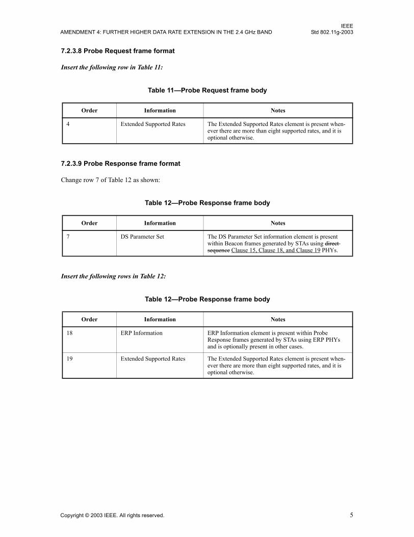
7.2.3.8 Probe Request frame format
Insert the following row in Table 11:
7.2.3.9 Probe Response frame format
Change row 7 of Table 12 as shown:
Insert the following rows in Table 12:
Table 11�Probe Request frame body
Order Information Notes
4 Extended Supported Rates The Extended Supported Rates element is present when-ever there are more than eight supported rates, and it is optional otherwise.
Table 12�Probe Response frame body
Order Information Notes
7 DS Parameter Set The DS Parameter Set information element is present within Beacon frames generated by STAs using direct sequence Clause 15, Clause 18, and Clause 19 PHYs.
Table 12�Probe Response frame body
Order Information Notes
18 ERP Information ERP Information element is present within Probe Response frames generated by STAs using ERP PHYs and is optionally present in other cases.
19 Extended Supported Rates The Extended Supported Rates element is present when-ever there are more than eight supported rates, and it is optional otherwise.
Copyright © 2003 IEEE. All rights reserved. 5
IEEEStd 802.11g-2003 LOCAL AND METROPOLITAN AREA NETWORKS
7.3 Management frame body components
7.3.1 Fixed fields
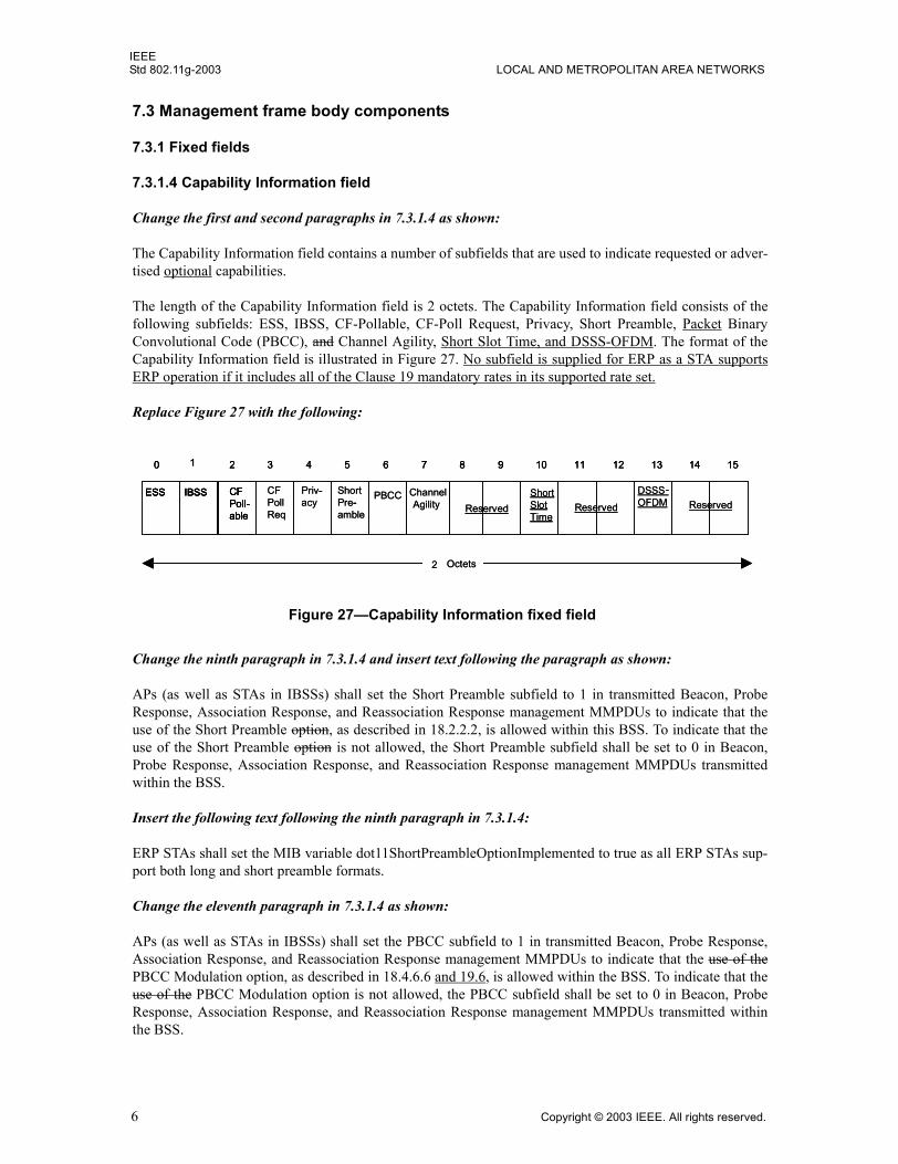
7.3.1.4 Capability Information field
Change the first and second paragraphs in 7.3.1.4 as shown:
The Capability Information field contains a number of subfields that are used to indicate requested or adver-tised optional capabilities.
The length of the Capability Information field is 2 octets. The Capability Information field consists of thefollowing subfields: ESS, IBSS, CF-Pollable, CF-Poll Request, Privacy, Short Preamble, Packet BinaryConvolutional Code (PBCC), and Channel Agility, Short Slot Time, and DSSS-OFDM. The format of theCapability Information field is illustrated in Figure 27. No subfield is supplied for ERP as a STA supportsERP operation if it includes all of the Clause 19 mandatory rates in its supported rate set.
Replace Figure 27 with the following:
Change the ninth paragraph in 7.3.1.4 and insert text following the paragraph as shown:
APs (as well as STAs in IBSSs) shall set the Short Preamble subfield to 1 in transmitted Beacon, ProbeResponse, Association Response, and Reassociation Response management MMPDUs to indicate that theuse of the Short Preamble option, as described in 18.2.2.2, is allowed within this BSS. To indicate that theuse of the Short Preamble option is not allowed, the Short Preamble subfield shall be set to 0 in Beacon,Probe Response, Association Response, and Reassociation Response management MMPDUs transmittedwithin the BSS.
Insert the following text following the ninth paragraph in 7.3.1.4:
ERP STAs shall set the MIB variable dot11ShortPreambleOptionImplemented to true as all ERP STAs sup-port both long and short preamble formats.
Change the eleventh paragraph in 7.3.1.4 as shown:
APs (as well as STAs in IBSSs) shall set the PBCC subfield to 1 in transmitted Beacon, Probe Response,Association Response, and Reassociation Response management MMPDUs to indicate that the use of thePBCC Modulation option, as described in 18.4.6.6 and 19.6, is allowed within the BSS. To indicate that theuse of the PBCC Modulation option is not allowed, the PBCC subfield shall be set to 0 in Beacon, ProbeResponse, Association Response, and Reassociation Response management MMPDUs transmitted withinthe BSS.
��� ���� ��
��
� �
��
�
���
�����
���
����
����
�� �
���� ������
������
����
����
� !" # $ % & ' ( � " # $ %
�����)"
����
��
*���
��� ���� ��
��
� �
�
�
�
��)����+ ��)����+��)����+
��� ���� ��
��
� �
��
�
���
�����
���
����
����
�� �
���� ������
������
����
����
� !" # $ % & ' ( � " # $ %� !" # $ % & ' ( � " # $ %
�����)"
����
��
*���
��� ���� ��
��
� �
�
�
�
��)����+ ��)����+��)����+
Figure 27�Capability Information fixed field
6 Copyright © 2003 IEEE. All rights reserved.
IEEEAMENDMENT 4: FURTHER HIGHER DATA RATE EXTENSION IN THE 2.4 GHz BAND Std 802.11g-2003
Change the thirteenth paragraph in 7.3.1.4 as shown:
Bit 7 of the Capability Information field shall be used to indicate Channel Agility capability by the HighRate direct sequence spread spectrum (HR/DSSS) or ERP PHYs. STAs shall set the Channel Agility bit to 1when Channel Agility is in use and shall set it to 0 otherwise.
Insert the following paragraphs before the last paragraph of 7.3.1.4:
STAs shall set the Short Slot Time subfield to 1 in transmitted Association Request and ReassociationRequest MMPDUs when the MIB attribute dot11ShortSlotTimeOptionImplemented anddot11ShortSlotTimeOptionEnabled are true. Otherwise, the STA shall set the Short Slot Time subfield to 0in transmitted Association Request and Reassociation Request MMPDUs.
If a STA that does not support Short Slot Time associates, the AP shall use long slot time beginning at thefirst Beacon subsequent to the association of the long slot time STA. APs shall set the Short Slot Time sub-field in transmitted Beacon, Probe Response, Association Response, and Reassociation Response MMPDUsto indicate the currently used slot time value within this BSS.
STAs shall set the MAC variable aSlotTime to the short slot value upon transmission or reception of Beacon,Probe Response, Association Response, and Reassociation Response MMPDUs from the BSS that the STAhas joined or started and that have the short slot subfield set to 1 when the MIB attributedot11ShortSlotTimeOptionImplemented is true. STAs shall set the MAC variable aSlotTime to the long slotvalue upon transmission or reception of Beacon, Probe Response, Association Response, and ReassociationResponse MMPDUs from the BSS that the STA has joined or started and that have the short slot subfield setto 0 when the MIB attribute dot11ShortSlotTimeOptionImplemented is true. STAs shall set the MAC vari-able aSlotTime to the long slot value at all times when the MIB attributedot11ShortSlotTimeOptionImplemented is false. When the dot11ShortSlotTimeOptionImplemented MIBattribute is not present, or when the PHY supports only a single slot time value, then the STA shall set theMAC variable aSlotTime to the slot value appropriate for the attached PHY.
For IBSS, the Short Slot Time subfield shall be set to 0.
APs as well as STAs in IBSSs shall set the DSSS-OFDM subfield to 1 in transmitted Beacon, ProbeResponse, Association Response, and Reassociation Response management MMPDUs to indicate that theuse of DSSS-OFDM, as described in 19.7, is allowed within this BSS or by STAs that want to use DSSS-OFDM within an IBSS. To indicate that the use of DSSS-OFDM is not allowed, the DSSS-OFDM subfieldshall be set to 0 in Beacon, Probe Response, Association Response, and Reassociation Response MMPDUstransmitted within the BSS.
STAs shall set the DSSS-OFDM subfield to 1 in transmitted Association Request and Reassociation RequestMMPDUs when the MIB attribute dot11DSSS-OFDMOptionImplemented and dot11DSSS-OFDMOption-Enabled are true. Otherwise, STAs shall set the DSSS-OFDM subfield to 0 in transmitted AssociationRequest and Reassociation Request MMPDUs.
Change the last paragraph in 7.3.1.4 as shown:
Unused bits 8-15 of the Capability Information field are reserved.
Copyright © 2003 IEEE. All rights reserved. 7
IEEEStd 802.11g-2003 LOCAL AND METROPOLITAN AREA NETWORKS
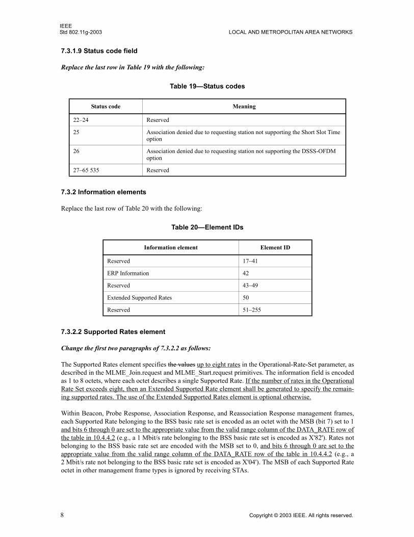
7.3.1.9 Status code field
Replace the last row in Table 19 with the following:
7.3.2 Information elements
Replace the last row of Table 20 with the following:
7.3.2.2 Supported Rates element
Change the first two paragraphs of 7.3.2.2 as follows:
The Supported Rates element specifies the values up to eight rates in the Operational-Rate-Set parameter, asdescribed in the MLME_Join.request and MLME_Start.request primitives. The information field is encodedas 1 to 8 octets, where each octet describes a single Supported Rate. If the number of rates in the OperationalRate Set exceeds eight, then an Extended Supported Rate element shall be generated to specify the remain-ing supported rates. The use of the Extended Supported Rates element is optional otherwise.
Within Beacon, Probe Response, Association Response, and Reassociation Response management frames,each Supported Rate belonging to the BSS basic rate set is encoded as an octet with the MSB (bit 7) set to 1and bits 6 through 0 are set to the appropriate value from the valid range column of the DATA_RATE row ofthe table in 10.4.4.2 (e.g., a 1 Mbit/s rate belonging to the BSS basic rate set is encoded as X'82'). Rates notbelonging to the BSS basic rate set are encoded with the MSB set to 0, and bits 6 through 0 are set to theappropriate value from the valid range column of the DATA_RATE row of the table in 10.4.4.2 (e.g., a2 Mbit/s rate not belonging to the BSS basic rate set is encoded as X'04'). The MSB of each Supported Rateoctet in other management frame types is ignored by receiving STAs.
Table 19�Status codes
Status code Meaning
22�24 Reserved
25 Association denied due to requesting station not supporting the Short Slot Time option
26 Association denied due to requesting station not supporting the DSSS-OFDM option
27�65 535 Reserved
Table 20�Element IDs
Information element Element ID
Reserved 17�41
ERP Information 42
Reserved 43�49
Extended Supported Rates 50
Reserved 51�255
8 Copyright © 2003 IEEE. All rights reserved.
IEEEAMENDMENT 4: FURTHER HIGHER DATA RATE EXTENSION IN THE 2.4 GHz BAND Std 802.11g-2003
Insert the following paragraph at the end of 7.3.2.2:
If the DSSS-OFDM bit is set to 1 in the transmitted Capability Information field of an MMPDU, then anysupported rates transmitted in that frame that include rates that are common to both DSSS-OFDM and ERP-OFDM shall be interpreted by receiving and transmitting STA to indicate support for both DSSS-OFDM andERP-OFDM at the indicated rate. However, if any of those rates are indicated as basic (a rate in the BSSBa-sicRateSet), then the basic rate designation shall be interpreted by receiving and transmitting STA to applyonly for the ERP-OFDM modulation and rate. If the PBCC bit is set to 1 in the transmitted capability field ofan MMPDU, then any supported rates transmitted in that frame that include rates that are common to bothPBCC and CCK shall be interpreted by receiving and transmitting STA to indicate support for both PBCCand CCK at the indicated rate. However, if any of those rates are indicated as basic, then the basic rate desig-nation shall be interpreted by receiving and transmitting STA to apply only for the CCK modulation andrate. That is, if the rate is indicated as basic, the basic designation does not apply to DSSS-OFDM, PBCC, orERP-PBCC.
Insert the following subclauses (7.3.2.13 and 7.3.2.14) at the end of 7.3.2:
7.3.2.13 ERP Information element
The ERP Information element contains information on the presence of Clause 15 or Clause 18 stations in theBSS that are not capable of Clause 19 (ERP-OFDM) data rates. It also contains the requirement of the ERPInformation element sender (AP in a BSS or STA in an IBSS) as to the use of protection mechanisms to opti-mize BSS performance and as to the use of long or short Barker preambles. See Figure 42E for a definitionof the frame element.
If one or more NonERP STAs are associated in the BSS, the Use_Protection bit shall be set to 1 in transmit-ted ERP Information Elements.
In an IBSS, the setting of the Use_Protection bit is left to the STA. In an IBSS, there is no uniform conceptof association; therefore, a typical algorithm for setting the Use_Protection bit will take into account the traf-fic pattern and history on the network. If a member of an IBSS detects one or more NonERP STAs that aremembers of the same IBSS, then the Use_Protection bit should be set to 1 in the ERP Information Elementof transmitted Beacon and Probe Response frames.
The NonERP_Present bit shall be set to 1 when a NonERP STA is associated with the BSS. Examples ofwhen the NonERP present bit may additionally be set to 1 include, but are not limited to, when
a) A NonERP infrastructure or independent BSS is overlapping (a NonERP BSS may be detected bythe reception of a Beacon where the supported rates contain only Clause 15 or Clause 18 rates).
b) In an IBSS, if a Beacon frame is received from one of the IBSS participants where the supported rateset contains only Clause 15 or Clause 18 rates.
c) A management frame (excluding a Probe Request) is received where the supported rate set includesonly Clause 15 or Clause 18 rates.
ERP APs and ERP STAs shall invoke the use of a protection mechanism after transmission or reception ofthe Use_Protection bit with a value of 1 in an MMPDU to or from the BSS that the ERP AP or ERP STA hasjoined or started. ERP APs and ERP STAs may additionally invoke protection mechanism use at other times.ERP APs and ERP STAs may disable protection mechanism use after transmission or reception of theUse_Protection bit with a value of 0 in an MMPDU to or from the BSS that the ERP AP or ERP STA hasjoined or started.
When there are no NonERP STAs associated with the BSS and the ERP Information Element sender�sdot11ShortPreambleOptionImplemented MIB variable is set to true, then the Barker_Preamble_Mode bitmay be set to 0. The Barker_Preamble_Mode bit shall be set to 1 by the ERP Information Element sender if
Copyright © 2003 IEEE. All rights reserved. 9

IEEEStd 802.11g-2003 LOCAL AND METROPOLITAN AREA NETWORKS
one or more associated NonERP STAs are not short preamble capable as indicated in their Capability Infor-mation field, or if the ERP Information Element senders dot11ShortPreambleOptionImplemented MIBvariable is set to false.
If a member of an IBSS detects one or more non-short preamble-capable STAs that are members of the sameIBSS, then the Barker_Preamble_Mode bit should be set to 1 in the transmitted ERP Information Element.
ERP APs and ERP STAs shall use long preambles when transmitting Clause 15, Clause 18, and Clause 19frames after transmission or reception of an ERP Information Element with a Barker_Preamble_Mode valueof 1 in an MMPDU to or from the BSS that the ERP AP or ERP STA has joined or started, regardless of thevalue of the short preamble capability bit from the same received or transmitted MMPDU that contained theERP Information Element. ERP APs and ERP STAs may additionally use long preambles when transmittingClause 15, Clause 18, and Clause 19 frames at other times. ERP APs and ERP STAs may use short pream-bles when transmitting Clause 15, Clause 18, and Clause 19 frames after transmission or reception of anERP Information Element with a Barker_Preamble_Mode value of 0 in an MMPDU to or from the BSS thatthe ERP AP or ERP STA has joined or started, regardless of the value of the short preamble capability bitfrom the same received or transmitted MMPDU. NonERP STAs and NonERP APs may also follow the rulesgiven in this paragraph.
Recommended behavior for setting the Use_Protection bit is contained in 9.10.
The ERP Information element shall have the form shown in Figure 42E.
Bits r3 through r7 are reserved, set to 0, and are ignored on reception. Note that the length of this element isflexible and may be expanded in the future.
7.3.2.14 Extended Supported Rates element
The Extended Supported Rates element specifies the rates in the OperationalRateSet as described in theMLME_JOIN.request and MLME_START.request primitives that are not carried in the Supported Rates ele-ment. The information field is encoded as 1 to 255 octets where each octet describes a single supported rate.
Within Beacon, Probe Response, Association Response, and Reassociation Response management frames,each supported rate belonging to the BSS basic rate set, as defined in 10.3.10.1, is encoded as an octet withthe msb (bit 7) set to 1 and bits 6 through 0 are set to the appropriate value from the valid range column of theDATA_RATE row of the table in 10.4.4.2 (e.g., a 1 Mbit/s rate belonging to the BSS basic rate set is encodedas X'82'). Rates not belonging to the BSS basic rate set are encoded with the msb set to 0, and bits 6 through0 are set to the appropriate value from the valid range column of the DATA_RATE row of the table in 10.4.4.2(e.g., a 2 Mbit/s rate not belonging to the BSS basic rate set is encoded as X'04'). The msb of each octet in theExtended Supported Rate element in other management frame types is ignored by receiving STAs.
BSS basic rate set information in Beacon and Probe Response management frames is used by STAs in orderto avoid associating with a BSS if they do not support all the data rates in the BSS basic rate set.
Figure 42E�ERP Information element
Octets 11
NonERPpresent
Length (1)Element ID r7r6r5r3UseProtection
r4BarkerPreamblemode
1Octets 11
NonERPpresent
Length (1)Element ID r7r6r5r3UseProtection
r4BarkerPreamblemode
1
10 Copyright © 2003 IEEE. All rights reserved.
IEEEAMENDMENT 4: FURTHER HIGHER DATA RATE EXTENSION IN THE 2.4 GHz BAND Std 802.11g-2003
For stations supporting eight or fewer data rates, this element is optional for inclusion in all of the frametypes that include the supported rates element. For stations supporting more than eight data rates, this ele-ment shall be included in all of the frame types that include the supported rates element.
The Extended Supported Rates element has the format shown in Figure 42F.
9. MAC sublayer functional description
9.2 DCF
Change the eleventh paragraph in 9.2 as shown:
The medium access protocol allows for stations to support different sets of data rates. All STAs shall be ableto receive and transmit at all the data rates in the aBasicRateSet specified parameter of theMLME_Join.request and MLME_Start.request primitives. To support the proper operation of the RTS/CTSand the virtual CS mechanism, all STAs shall be able to detect the RTS and CTS frames. For this reason, theRTS and CTS frames shall be transmitted at one of the rates in the BSS basic rate set. (See 9.6 for a descrip-tion of multirate operation.)
Insert the following subclauses after 9.2.10:
9.2.11 NAV distribution
When a node needs to distribute NAV information, for instance, to reserve the medium for a transmission ofa non-basic rate frame (that may not be heard by other nodes in the BSS), the node may first transmit a CTSframe with the RA field equal to its own MAC address (CTS-to-self) and with a duration value that protectsthe pending transmission, plus possibly an ACK frame.
The CTS-to-self NAV distribution mechanism is lower in network overhead cost than is the RTS/CTS NAVdistribution mechanism, but CTS-to-self is less robust against hidden nodes and collisions than RTS/CTS.STAs employing a NAV distribution mechanism should choose a mechanism such as CTS-to-self or RTS/CTS that is appropriate for the given network conditions. If errors occur when employing the CTS-to-selfmechanism, STAs should switch to a more robust mechanism.
9.2.12 Determination of PLME aCWmin characteristics
In the case of the Clause 19 Extended Rate PHY, the aCWmin value is dependent on the requestor�s charac-teristic rate set. The characteristic rate set is equal to the IBSS�s supported rate set when the STA is operatingas a member of an IBSS. It is equal to the AP�s supported rate set when the STA is associated with an AP. Atall other times, it is equal to the STA�s mandatory rate set. The MAC variable aCWmin is set to aCWmin(0)if the characteristic rate set includes only rates in the set 1, 2, 5.5, 11 otherwise, aCWmin is set to aCW-min(1). If the returned value for aCWmin is a scalar, then the MAC always sets the variable aCWmin to thereturned scalar value of aCWmin.
Figure 42F�Extended Supported Rates element format
Length E lem ent ID
O ctets 1 1-2551
Extended Supported R ates Length E lem ent ID
O ctets 1 1-2551
Extended Supported R ates
Copyright © 2003 IEEE. All rights reserved. 11
IEEEStd 802.11g-2003 LOCAL AND METROPOLITAN AREA NETWORKS
9.6 Multirate support
Change the text of 9.6 as shown:
Some PHYs have multiple data transfer rate capabilities that allow implementations to perform dynamic rateswitching with the objective of improving performance. The algorithm for performing rate switching isbeyond the scope of this standard, but in order to ensure coexistence and interoperability on multirate-capable PHYs, this standard defines a set of rules that shall to be followed by all STAs.
All control frames shall be transmitted at one of the rates in the BSS basic rate set so that they will beunderstood.
All control frames that initiate a frame exchange shall be transmitted at one of the rates in theBSSBasicRateSet, unless the transmitting STAs protection mechanism is enabled, and the control frame is aprotection mechanism frame; in which case, the control frame shall be transmitted at a rate according to theseparate rules for determining the rates of transmission of protection frames in 9.10.
All frames with multicast or broadcast receiver in the addresses1 field shall be transmitted at one of the ratesincluded in the BSS basic rate set, regardless of their type or subtype.
Data and/or management MPDUs with a unicast receiver in addresses1 shall be sent on any supporteddata rate selected by a rate switching mechanism (whose output is an internal MAC variable called MAC-CurrentRate, which is used for calculating the Duration/ID field of each frame). An No STA shall nottransmit a unicast frame at a rate that is known not to be supported by the destination STA, as reported inany Supported Rates and Extended Supported Rates element in the management frames. For frames oftype Data + CF � ACK, Data + CF � Poll + CF � ACK, and CF � Poll + CF � ACK, the rate chosen totransmit the frame should be supported by both the addressed recipient STA and the STA to which theACK is intended.
Under no circumstances shall a STA initiate transmission of a data or management frame at a data ratehigher than the greatest rate in the OperationalRateSet, a parameter of the MLME_JOIN.request primitive.
To allow the transmitting STA to calculate the contents of the Duration/ID field, the responding a STAresponding to a received frame shall transmit its Control Response and Management Response frames(either CTS or ACK) frames at the highest rate in the BSSBasicRateSet that is less than or equal to the rateof the immediately previous frame in the frame exchange sequence (as defined in 9.7) and that is of the samemodulation type as the received frame. If no rate in the basic rate set meets these conditions, then the controlframe sent in response to a received frame shall be transmitted at the highest mandatory rate of the PHY thatis less than or equal to the rate of the received frame, and that is of the same modulation type as the receivedframe. In addition, the Control Response frame shall be sent using the same PHY options as the receivedframe, unless they conflict with the requirement to use the BSSBasicRateSet.
An alternative rate for the control response frame may be used, provided that the duration of the controlresponse frame at the alternative rate is the same as the duration of the control response frame at the origi-nally chosen rate and the alternative rate is in either the BSSBasicRateSet or the mandatory rate set of thePHY and the modulation of the control response frame at the alternative rate is the same type as that of thereceived frame.
For the HR/DSSS PHY, the time required to transmit a frame for use in the Duration/ID field is determinedusing the PLME-TXTIME.request primitive and the PLME-TXTIME.confirm primitive (see 10.4.7).
For the 5 GHz PHY Clause 17, Clause 18, and Clause 19 PHYs, the time required to transmit a frame for usein the Duration/ID field is determined using the PLME-TXTIME.request primitive (see 10.4.6) and thePLME-TXTIME.confirm primitive (see 10.4.7) The calculation method of TXTIME duration is defined in17.4.3, both defined in 17.4.3, 18.3.4, 19.8.3.1, 19.8.3.2, or 19.8.3.3 depending on the PHY options.
12 Copyright © 2003 IEEE. All rights reserved.
IEEEAMENDMENT 4: FURTHER HIGHER DATA RATE EXTENSION IN THE 2.4 GHz BAND Std 802.11g-2003
9.7 Frame exchange sequences
Change rows 1 and 2 and insert a new row following row 2 in Table 21 as shown:
Insert the following subclause at the end of Clause 9:
9.10 Protection mechanism
The intent of a protection mechanism is to ensure that a STA does not transmit an MPDU of type Data or anMMPDU with an ERP-OFDM preamble and header unless it has attempted to update the NAV of receivingNonERP STAs. The updated NAV period shall be longer than or equal to the total time required to send thedata and any required response frames. ERP STAs shall use protection mechanisms (such as RTS/CTS orCTS-to-self) for ERP-OFDM MPDUs of type Data or an MMPDU when the Use_Protection field of theERP Information element is set to 1 (see the requirements of 9.2.6). Protection mechanisms frames shall besent using one of the mandatory Clause 15 or Clause 18 rates and using one of the mandatory Clause 15 orClause 18 waveforms, so all STAs in the BSA will know the duration of the exchange even if they cannotdetect the ERP-OFDM signals using their CCA function.
Note that when using the Clause 19 options, ERP-PBCC or DSSS-OFDM, there is no need to use protectionmechanisms, as these frames start with a DSSS header.
In the case of a BSS composed of only ERP STAs, but with knowledge of a neighboring co-channel BSShaving NonERP traffic, the AP may require protection mechanisms to protect the BSS�s traffic from inter-ference. This will provide propagation of NAV to all attached STAs and all STAs in a neighboring co-channel BSS within range by BSS basic rate set modulated messages. The frames that propagate the NAVthroughout the BSS include RTS/CTS/ACK frames, all data frames with the �more fragments� field set to 1,all data frames sent in response to PS-Poll that are not proceeded in the frame sequence by a data frame withthe �more fragments� field set to 1, Beacon frames with nonzero CF time, and CF-End frames.
When RTS/CTS is used as the protection mechanism, cases exist such as NAV resetting (discretionary, asindicated in 9.2.5.4), where a hidden station may reset its NAV and this may cause a collision. The likeli-hood of occurrence is low, and it is not considered to represent a significant impairment to overall systemoperation. A mechanism to address this possible situation would be to use alternative protection mecha-nisms, or to revert to alternative modulation methods.
If a protection mechanism is being used, a fragment sequence may only employ ERP-OFDM modulation forthe final fragment and control response.
The rules for calculating RTS/CTS NAV fields are unchanged when using RTS/CTS as a protectionmechanism.
Additionally, if any of the rates in the BSSBasicRateSet of the protection mechanism frame transmittingSTA�s BSS are Clause 15 or Clause 18 rates, then the protection mechanism frames shall be sent at one ofthose Clause 15 or Clause 18 basic rates.
Table 21�Frame sequences
Sequence Frames in sequence Usage
{CTS-} Data(bc/mc) 1 or 2 Broadcast or multicast MSDU
{CTS-} Mgmt(bc) 1 or 2 Broadcast MMPDU
CTS - [Frag - ACK -] Last - ACK 3 or more Protected directed MSDU or MMPDU
Copyright © 2003 IEEE. All rights reserved. 13
IEEEStd 802.11g-2003 LOCAL AND METROPOLITAN AREA NETWORKS
10. Layer management
10.4 PLME SAP interface
10.4.4 PLME-DSSSTESTMODE
10.4.4.2 PLME-DSSSTESTMODE.request
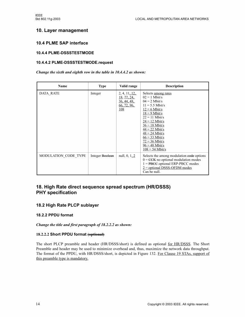
Change the sixth and eighth row in the table in 10.4.4.2 as shown:
18. High Rate direct sequence spread spectrum (HR/DSSS) PHY specification
18.2 High Rate PLCP sublayer
18.2.2 PPDU format
Change the title and first paragraph of 18.2.2.2 as shown:
18.2.2.2 Short PPDU format (optional)
The short PLCP preamble and header (HR/DSSS/short) is defined as optional for HR/DSSS. The ShortPreamble and header may be used to minimize overhead and, thus, maximize the network data throughput.The format of the PPDU, with HR/DSSS/short, is depicted in Figure 132. For Clause 19 STAs, support ofthis preamble type is mandatory.
Name Type Valid range Description
DATA_RATE Integer 2, 4, 11, 12, 18, 22, 24, 36, 44, 48, 66, 72, 96, 108
Selects among rates 02 = 1 Mbit/s04 = 2 Mbit/s11 = 5.5 Mbit/s12 = 6 Mbit/s18 = 9 Mbit/s22 = 11 Mbit/s24 = 12 Mbit/s36 = 18 Mbit/s44 = 22 Mbit/s48 = 24 Mbit/s66 = 33 Mbit/s72 = 36 Mbit/s96 = 48 Mbit/s108 = 54 Mbit/s
MODULATION_CODE_TYPE Integer Boolean null, 0, 1, 2 Selects the among modulation code options0 = CCK no optional modulation modes1 = PBCC optional ERP-PBCC modes2 = optional DSSS-OFDM modesCan be null.
14 Copyright © 2003 IEEE. All rights reserved.
IEEEAMENDMENT 4: FURTHER HIGHER DATA RATE EXTENSION IN THE 2.4 GHz BAND Std 802.11g-2003
Insert new Clause 19 as follows:
19. Extended Rate PHY specification
19.1 Overview
This clause specifies further rate extension of the PHY for the Direct Sequence Spread Spectrum (DSSS)system of Clause 15 and the extensions of Clause 18. Hereinafter the PHY defined in this clause will beknown as the Extended Rate PHY (ERP). This PHY operates in the 2.4 GHz ISM band.
19.1.1 Introduction
The ERP builds on the payload data rates of 1 and 2 Mbit/s, as described in Clause 15, that use DSSSmodulation and builds on the payload data rates of 1, 2, 5.5, and 11 Mbit/s, as described in Clause 18, thatuse DSSS, CCK, and optional PBCC modulations. The ERP draws from Clause 17 to provide additionalpayload data rates of 6, 9, 12, 18, 24, 36, 48, and 54 Mbit/s. Of these rates, transmission and receptioncapability for 1, 2, 5.5, 11, 6, 12, and 24 Mbit/s data rates is mandatory.
Two additional optional ERP-PBCC modulation modes with payload data rates of 22 and 33 Mbit/s aredefined. An ERP-PBCC station may implement 22 Mbit/s alone or 22 and 33 Mbit/s. An optionalmodulation mode known as DSSS-OFDM is also incorporated with payload data rates of 6, 9, 12, 18, 24, 36,48, and 54 Mbit/s.
19.1.2 Operational modes
The radio portion of all Clause 19-compliant ERP systems implements all mandatory modes of Clause 17and Clause 18, except it uses the 2.4 GHz frequency band and channelization plan specified in 18.4.6. TheERP has the capability to decode all Clause 15 and Clause 18 PLCPs and all ERP-OFDM PLCPs. In addi-tion, it is mandatory that all ERP-compliant equipment be capable of sending and receiving the shortpreamble that is (and remains) optional for Clause 18 PHYs.
The ERP has the capability to detect ERP and Clause 18 preambles whenever a clear channel assessment(CCA) is requested. Because protection mechanisms are not required in all cases, the ERP CCA mechanismsfor all preamble types shall be active at all times.
An ERP BSS is capable of operating in any combination of available ERP modes (Clause 19 PHYs) andNonERP modes (Clause 15 or Clause 18 PHYs). For example, a BSS could operate in an ERP-OFDM-onlymode, a mixed mode of ERP-OFDM and ERP-DSSS/CCK, or a mixed mode of ERP-DSSS/CCK and Non-ERP. When options are enabled, combinations are also allowed.
The changes to the base standard required to implement the ERP are summarized as follows:
a) ERP-DSSS/CCK 1) The PHY uses the capabilities of Clause 18 with the following exceptions:
i) Support of the short PLCP PPDU header format capability of 18.2.2.2 is mandatory.ii) CCA (see 18.4.8.4) has a mechanism that will detect all mandatory Clause 19 sync
symbols.iii) The maximum input signal level (see 18.4.8.2) is �20 dBm.iv) Locking the transmit center frequency and the symbol clock frequency to the same
reference oscillator is mandatory.
Copyright © 2003 IEEE. All rights reserved. 15
IEEEStd 802.11g-2003 LOCAL AND METROPOLITAN AREA NETWORKS
b) ERP-OFDM 1) The PHY uses the capabilities of Clause 17 with the following exceptions:
i) The frequency plan is in accordance with 18.4.6.1 and 18.4.6.2 instead of 17.3.8.3.ii) CCA has a mechanism that will detect all mandatory Clause 19 sync symbols.iii) The frequency accuracy (see 17.3.9.4 and 17.3.9.5) is ±25 PPM.iv) The maximum input signal level (see 17.3.10.4) is -20 dBm.v) The slot time is 20 µs in accordance with 18.3.3, except that an optional 9 µs slot time may
be used when the BSS consists of only ERP STAs.vi) SIFS time is 10 µs in accordance with 18.3.3. See 19.3.2.3 for more detail.
c) ERP-PBCC (Optional)1) This is a single-carrier modulation scheme that encodes the payload using a 256-state packet
binary convolutional code. These are extensions to the PBCC modulation in Clause 18. ERP-PBCC modes with payload data rates of 22 and 33 Mbit/s are defined in 19.6.
d) DSSS-OFDM (Optional)1) This is a hybrid modulation combining a DSSS preamble and header with an OFDM payload
transmission. DSSS-OFDM modes with payload data rates of 6, 9, 12, 18, 24, 36, 48, and54 Mbit/s are defined in 19.7.
2) If the optional DSSS-OFDM mode is used, the supported rates in that mode are the same as theERP-OFDM supported rates.
The 2.4 GHz ISM band is a shared medium, and coexistence with other devices such as Clause 15 and Clause18 STAs is an important issue for maintaining high performance in Clause 19 (ERP) STAs. The ERP modu-lations (ERP-OFDM, ERP-PBCC, and DSSS-OFDM) have been designed to coexist with existing Clause 15and Clause 18 STAs. This coexistence is achieved by several means, including virtual carrier sense (RTS/CTS or CTS-to-self), carrier sense and collision avoidance protocols, and MSDU fragmentation.
19.1.3 Scope
This clause specifies the ERP entity and the deviations from earlier clauses to accommodate it. It is orga-nized by reference to the relevant earlier clauses to avoid excessive duplication.
The Extended Rate PHY layer consists of the following two protocol functions:
a) A physical layer convergence function that adapts the capabilities of the physical medium dependent(PMD) system to the PHY service available. This function is supported by the PHY layer conver-gence procedure (PLCP), which defines a method for mapping the MAC sublayer protocol dataunits (MPDU) into a framing format suitable for sending and receiving user data and managementinformation between two or more STAs using the associated PMD system. The PHY exchangesPHY protocol data units (PPDU) that contain PLCP service data units (PSDU). The MAC uses thePHY service, so each MPDU corresponds to a PSDU that is carried in a PPDU.
b) A PMD system, whose function defines the characteristics and method of transmitting and receivingdata through a wireless medium between two or more STAs; each using the ERP.
19.1.4 Extended Rate PHY functions
The architecture of the ERP is depicted in the ISO/IEC basic reference model shown in Figure 141 of 18.4.1.The ERP contains three functional entities: the PMD function, the PHY convergence function (PLCP), andthe layer management function.
The ERP service is provided to the MAC through the PHY service primitives described in Clause 12.Interoperability is addressed by use of the carrier sense mechanism specified in 9.2.1 and the protectionmechanism in 9.10. This mechanism allows NonERP stations to know of ERP traffic that they cannotdemodulate so that they may defer the medium to that traffic.
16 Copyright © 2003 IEEE. All rights reserved.
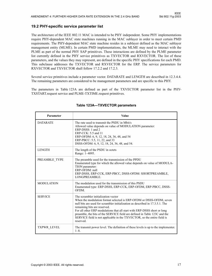
IEEEAMENDMENT 4: FURTHER HIGHER DATA RATE EXTENSION IN THE 2.4 GHz BAND Std 802.11g-2003
19.2 PHY-specific service parameter list
The architecture of the IEEE 802.11 MAC is intended to be PHY independent. Some PHY implementationsrequire PHY-dependent MAC state machines running in the MAC sublayer in order to meet certain PMDrequirements. The PHY-dependent MAC state machine resides in a sublayer defined as the MAC sublayermanagement entity (MLME). In certain PMD implementations, the MLME may need to interact with thePLME as part of the normal PHY SAP primitives. These interactions are defined by the PLME parameterlist currently defined in the PHY service primitives as TXVECTOR and RXVECTOR. The list of theseparameters, and the values they may represent, are defined in the specific PHY specifications for each PMD.This subclause addresses the TXVECTOR and RXVECTOR for the ERP. The service parameters forRXVECTOR and TXVECTOR shall follow 17.2.2 and 17.2.3.
Several service primitives include a parameter vector. DATARATE and LENGTH are described in 12.3.4.4.The remaining parameters are considered to be management parameters and are specific to this PHY.
The parameters in Table 123A are defined as part of the TXVECTOR parameter list in the PHY-TXSTART.request service and PLME-TXTIME.request primitives.
Table 123A�TXVECTOR parameters
Parameter Value
DATARATE The rate used to transmit the PSDU in Mbit/sAllowed value depends on value of MODULATION parameter:ERP-DSSS: 1 and 2ERP-CCK: 5.5 and 11ERP-OFDM: 6, 9, 12, 18, 24, 36, 48, and 54ERP-PBCC: 5.5, 11, 22, and 33DSSS-OFDM: 6, 9, 12, 18, 24, 36, 48, and 54.
LENGTH The length of the PSDU in octetsRange: 1�4095.
PREAMBLE_TYPE The preamble used for the transmission of the PPDUEnumerated type for which the allowed value depends on value of MODULA-TION parameter:ERP-OFDM: nullERP-DSSS, ERP-CCK, ERP-PBCC, DSSS-OFDM: SHORTPREAMBLE, LONGPREAMBLE.
MODULATION The modulation used for the transmission of this PSDUEnumerated type: ERP-DSSS, ERP-CCK, ERP-OFDM, ERP-PBCC, DSSS-OFDM.
SERVICE The scrambler initialization vectorWhen the modulation format selected is ERP-OFDM or DSSS-OFDM, seven null bits are used for scrambler initialization as described in 17.3.5.1. The remaining bits are reserved.For all other ERP modulations that all start with ERP-DSSS short or long preamble, the bits of the SERVICE field are defined in Table 123C and the SERVICE field is not applicable in the TXVECTOR, so the entire field is reserved.
TXPWR_LEVEL The transmit power level. The definition of these levels is up to the implementer.1�8.
Copyright © 2003 IEEE. All rights reserved. 17
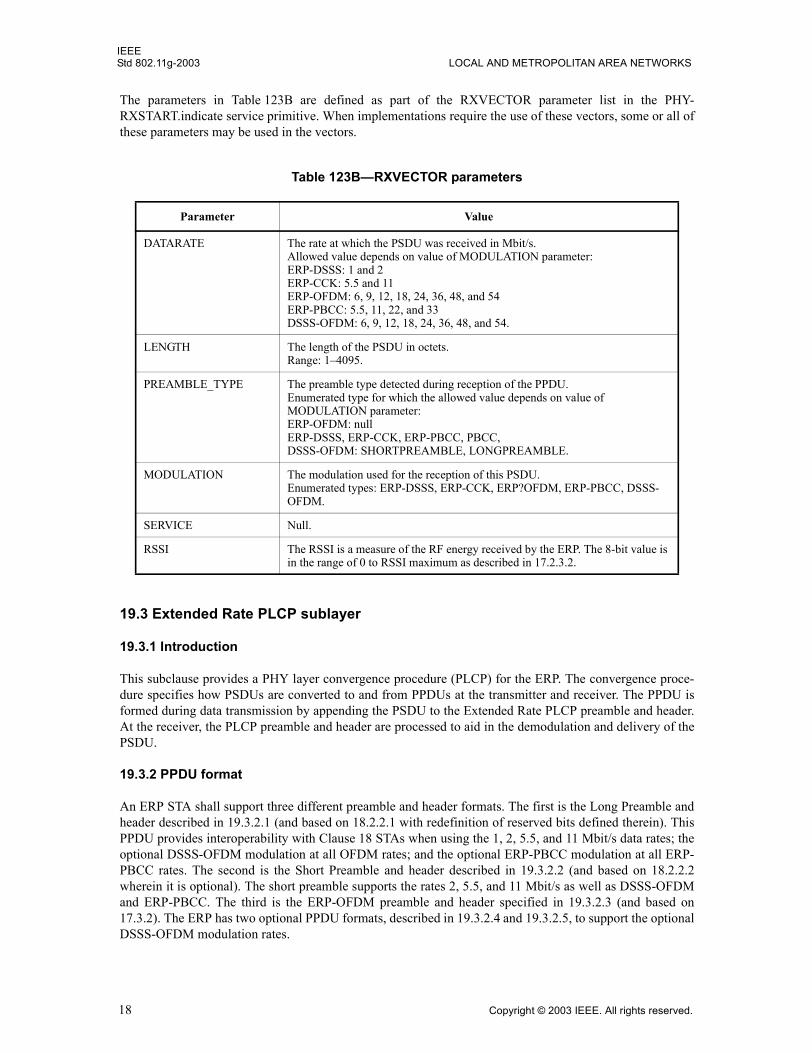
IEEEStd 802.11g-2003 LOCAL AND METROPOLITAN AREA NETWORKS
The parameters in Table 123B are defined as part of the RXVECTOR parameter list in the PHY-RXSTART.indicate service primitive. When implementations require the use of these vectors, some or all ofthese parameters may be used in the vectors.
19.3 Extended Rate PLCP sublayer
19.3.1 Introduction
This subclause provides a PHY layer convergence procedure (PLCP) for the ERP. The convergence proce-dure specifies how PSDUs are converted to and from PPDUs at the transmitter and receiver. The PPDU isformed during data transmission by appending the PSDU to the Extended Rate PLCP preamble and header.At the receiver, the PLCP preamble and header are processed to aid in the demodulation and delivery of thePSDU.
19.3.2 PPDU format
An ERP STA shall support three different preamble and header formats. The first is the Long Preamble andheader described in 19.3.2.1 (and based on 18.2.2.1 with redefinition of reserved bits defined therein). ThisPPDU provides interoperability with Clause 18 STAs when using the 1, 2, 5.5, and 11 Mbit/s data rates; theoptional DSSS-OFDM modulation at all OFDM rates; and the optional ERP-PBCC modulation at all ERP-PBCC rates. The second is the Short Preamble and header described in 19.3.2.2 (and based on 18.2.2.2wherein it is optional). The short preamble supports the rates 2, 5.5, and 11 Mbit/s as well as DSSS-OFDMand ERP-PBCC. The third is the ERP-OFDM preamble and header specified in 19.3.2.3 (and based on17.3.2). The ERP has two optional PPDU formats, described in 19.3.2.4 and 19.3.2.5, to support the optionalDSSS-OFDM modulation rates.
Table 123B�RXVECTOR parameters
Parameter Value
DATARATE The rate at which the PSDU was received in Mbit/s. Allowed value depends on value of MODULATION parameter:ERP-DSSS: 1 and 2ERP-CCK: 5.5 and 11ERP-OFDM: 6, 9, 12, 18, 24, 36, 48, and 54ERP-PBCC: 5.5, 11, 22, and 33DSSS-OFDM: 6, 9, 12, 18, 24, 36, 48, and 54.
LENGTH The length of the PSDU in octets.Range: 1�4095.
PREAMBLE_TYPE The preamble type detected during reception of the PPDU.Enumerated type for which the allowed value depends on value of MODULATION parameter:ERP-OFDM: nullERP-DSSS, ERP-CCK, ERP-PBCC, PBCC, DSSS-OFDM: SHORTPREAMBLE, LONGPREAMBLE.
MODULATION The modulation used for the reception of this PSDU. Enumerated types: ERP-DSSS, ERP-CCK, ERP?OFDM, ERP-PBCC, DSSS-OFDM.
SERVICE Null.
RSSI The RSSI is a measure of the RF energy received by the ERP. The 8-bit value is in the range of 0 to RSSI maximum as described in 17.2.3.2.
18 Copyright © 2003 IEEE. All rights reserved.
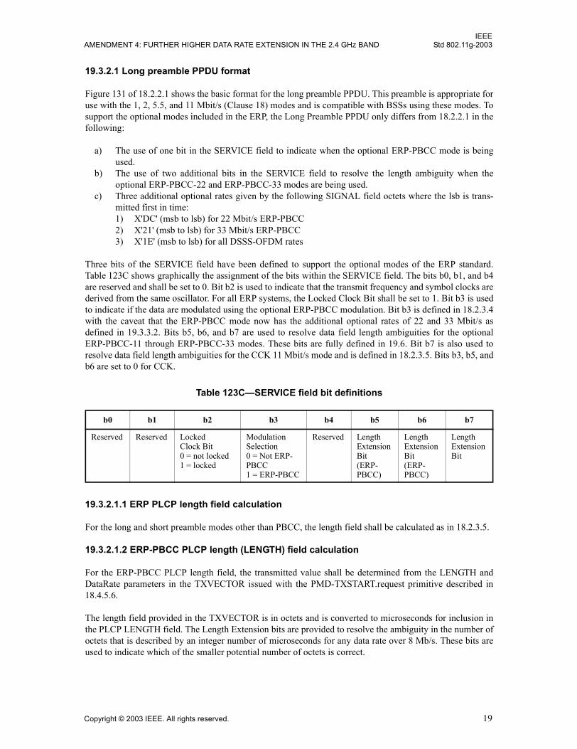
IEEEAMENDMENT 4: FURTHER HIGHER DATA RATE EXTENSION IN THE 2.4 GHz BAND Std 802.11g-2003
19.3.2.1 Long preamble PPDU format
Figure 131 of 18.2.2.1 shows the basic format for the long preamble PPDU. This preamble is appropriate foruse with the 1, 2, 5.5, and 11 Mbit/s (Clause 18) modes and is compatible with BSSs using these modes. Tosupport the optional modes included in the ERP, the Long Preamble PPDU only differs from 18.2.2.1 in thefollowing:
a) The use of one bit in the SERVICE field to indicate when the optional ERP-PBCC mode is beingused.
b) The use of two additional bits in the SERVICE field to resolve the length ambiguity when theoptional ERP-PBCC-22 and ERP-PBCC-33 modes are being used.
c) Three additional optional rates given by the following SIGNAL field octets where the lsb is trans-mitted first in time:1) X'DC' (msb to lsb) for 22 Mbit/s ERP-PBCC2) X'21' (msb to lsb) for 33 Mbit/s ERP-PBCC3) X'1E' (msb to lsb) for all DSSS-OFDM rates
Three bits of the SERVICE field have been defined to support the optional modes of the ERP standard.Table 123C shows graphically the assignment of the bits within the SERVICE field. The bits b0, b1, and b4are reserved and shall be set to 0. Bit b2 is used to indicate that the transmit frequency and symbol clocks arederived from the same oscillator. For all ERP systems, the Locked Clock Bit shall be set to 1. Bit b3 is usedto indicate if the data are modulated using the optional ERP-PBCC modulation. Bit b3 is defined in 18.2.3.4with the caveat that the ERP-PBCC mode now has the additional optional rates of 22 and 33 Mbit/s asdefined in 19.3.3.2. Bits b5, b6, and b7 are used to resolve data field length ambiguities for the optionalERP-PBCC-11 through ERP-PBCC-33 modes. These bits are fully defined in 19.6. Bit b7 is also used toresolve data field length ambiguities for the CCK 11 Mbit/s mode and is defined in 18.2.3.5. Bits b3, b5, andb6 are set to 0 for CCK.
19.3.2.1.1 ERP PLCP length field calculation
For the long and short preamble modes other than PBCC, the length field shall be calculated as in 18.2.3.5.
19.3.2.1.2 ERP-PBCC PLCP length (LENGTH) field calculation
For the ERP-PBCC PLCP length field, the transmitted value shall be determined from the LENGTH andDataRate parameters in the TXVECTOR issued with the PMD-TXSTART.request primitive described in18.4.5.6.
The length field provided in the TXVECTOR is in octets and is converted to microseconds for inclusion inthe PLCP LENGTH field. The Length Extension bits are provided to resolve the ambiguity in the number ofoctets that is described by an integer number of microseconds for any data rate over 8 Mb/s. These bits areused to indicate which of the smaller potential number of octets is correct.
Table 123C�SERVICE field bit definitions
b0 b1 b2 b3 b4 b5 b6 b7
Reserved Reserved Locked Clock Bit0 = not locked1 = locked
Modulation Selection0 = Not ERP-PBCC1 = ERP-PBCC
Reserved Length Extension Bit(ERP-PBCC)
Length Extension Bit(ERP-PBCC)
Length Extension Bit
Copyright © 2003 IEEE. All rights reserved. 19
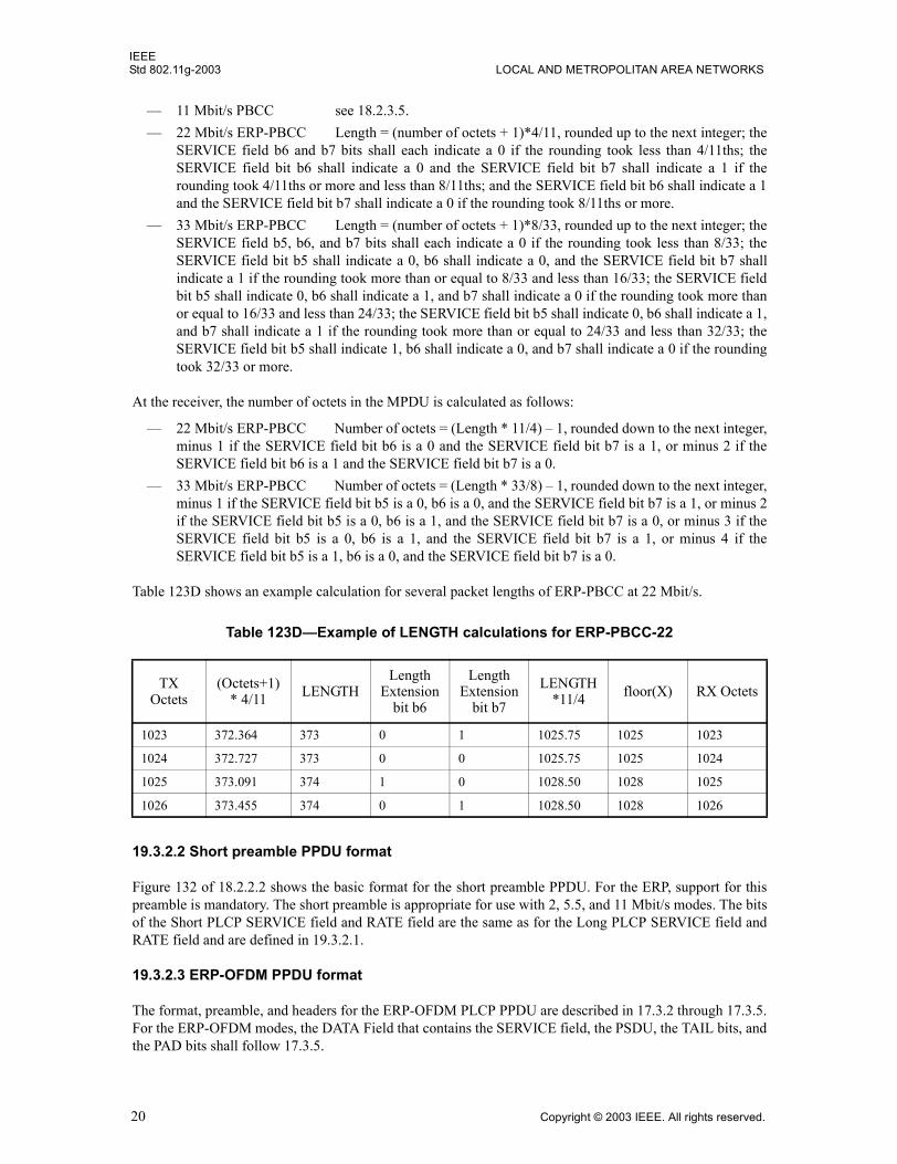
IEEEStd 802.11g-2003 LOCAL AND METROPOLITAN AREA NETWORKS
� 11 Mbit/s PBCC see 18.2.3.5.� 22 Mbit/s ERP-PBCC Length = (number of octets + 1)*4/11, rounded up to the next integer; the
SERVICE field b6 and b7 bits shall each indicate a 0 if the rounding took less than 4/11ths; theSERVICE field bit b6 shall indicate a 0 and the SERVICE field bit b7 shall indicate a 1 if therounding took 4/11ths or more and less than 8/11ths; and the SERVICE field bit b6 shall indicate a 1and the SERVICE field bit b7 shall indicate a 0 if the rounding took 8/11ths or more.
� 33 Mbit/s ERP-PBCC Length = (number of octets + 1)*8/33, rounded up to the next integer; theSERVICE field b5, b6, and b7 bits shall each indicate a 0 if the rounding took less than 8/33; theSERVICE field bit b5 shall indicate a 0, b6 shall indicate a 0, and the SERVICE field bit b7 shallindicate a 1 if the rounding took more than or equal to 8/33 and less than 16/33; the SERVICE fieldbit b5 shall indicate 0, b6 shall indicate a 1, and b7 shall indicate a 0 if the rounding took more thanor equal to 16/33 and less than 24/33; the SERVICE field bit b5 shall indicate 0, b6 shall indicate a 1,and b7 shall indicate a 1 if the rounding took more than or equal to 24/33 and less than 32/33; theSERVICE field bit b5 shall indicate 1, b6 shall indicate a 0, and b7 shall indicate a 0 if the roundingtook 32/33 or more.
At the receiver, the number of octets in the MPDU is calculated as follows:
� 22 Mbit/s ERP-PBCC Number of octets = (Length * 11/4) � 1, rounded down to the next integer,minus 1 if the SERVICE field bit b6 is a 0 and the SERVICE field bit b7 is a 1, or minus 2 if theSERVICE field bit b6 is a 1 and the SERVICE field bit b7 is a 0.
� 33 Mbit/s ERP-PBCC Number of octets = (Length * 33/8) � 1, rounded down to the next integer,minus 1 if the SERVICE field bit b5 is a 0, b6 is a 0, and the SERVICE field bit b7 is a 1, or minus 2if the SERVICE field bit b5 is a 0, b6 is a 1, and the SERVICE field bit b7 is a 0, or minus 3 if theSERVICE field bit b5 is a 0, b6 is a 1, and the SERVICE field bit b7 is a 1, or minus 4 if theSERVICE field bit b5 is a 1, b6 is a 0, and the SERVICE field bit b7 is a 0.
Table 123D shows an example calculation for several packet lengths of ERP-PBCC at 22 Mbit/s.
19.3.2.2 Short preamble PPDU format
Figure 132 of 18.2.2.2 shows the basic format for the short preamble PPDU. For the ERP, support for thispreamble is mandatory. The short preamble is appropriate for use with 2, 5.5, and 11 Mbit/s modes. The bitsof the Short PLCP SERVICE field and RATE field are the same as for the Long PLCP SERVICE field andRATE field and are defined in 19.3.2.1.
19.3.2.3 ERP-OFDM PPDU format
The format, preamble, and headers for the ERP-OFDM PLCP PPDU are described in 17.3.2 through 17.3.5.For the ERP-OFDM modes, the DATA Field that contains the SERVICE field, the PSDU, the TAIL bits, andthe PAD bits shall follow 17.3.5.
Table 123D�Example of LENGTH calculations for ERP-PBCC-22
TX Octets
(Octets+1) * 4/11 LENGTH
Length Extension
bit b6
Length Extension
bit b7
LENGTH *11/4 floor(X) RX Octets
1023 372.364 373 0 1 1025.75 1025 1023
1024 372.727 373 0 0 1025.75 1025 1024
1025 373.091 374 1 0 1028.50 1028 1025
1026 373.455 374 0 1 1028.50 1028 1026
20 Copyright © 2003 IEEE. All rights reserved.
IEEEAMENDMENT 4: FURTHER HIGHER DATA RATE EXTENSION IN THE 2.4 GHz BAND Std 802.11g-2003
For ERP-OFDM modes, an ERP packet is followed by a period of no transmission with a length of 6 µscalled the signal extension. The purpose of this extension is to make the TXTIME calculation in 19.8.3result in a transmission duration interval that includes an additional 6 µs. The SIFS time for Clause 17 pack-ets is 16 µs, and the SIFS time for Clause 18 packets is 10 µs. The longer SIFS time in Clause 17 is to allowextra time for the convolutional decode process to finish. As Clause 19 packets will use a SIFS time of 10µs, this extra 6 µs length extension is used to ensure that the Transmitter computes the Duration field in theMAC header incorporating the 6 µs of �idle time� following each ERP-OFDM transmission. This ensuresthat the NAV value of Clause 18 STAs is set correctly.
The �carrier-sense mechanism� described in 9.2.1 combines the NAV state and the STA�s transmitter statuswith physical carrier sense to determine the busy/idle state of the medium. The time interval between framesis called the inter-frame spacing (IFS). A STA shall determine that the medium is idle through the use of theCCA mechanism for the interval specified. The starting reference of slot boundaries is the end of the lastsymbol of the previous frame on the medium. For ERP-OFDM frames, this includes the length extension.For ERP-OFDM frames, a STA shall generate the PHY RX_END indication, 6 µs after the end of the lastsymbol of the previous frame on the medium. This adjustment shall be performed by the STA based on localconfiguration information set using the PLME SAP.
19.3.2.4 DSSS-OFDM long preamble PPDU format
Both long and short preambles and headers as previously described in 19.3.2.1 and 19.3.2.2 are used withDSSS-OFDM.
For all DSSS-OFDM rates and preamble modes, the PLCP SIGNAL Field described in 18.2.3.3 shall be setto a 3 Mbit/s value. That is, the eight-bit value is set to X'1E' (msb to lsb). For DSSS-OFDM, this value issimply a default setting used for BSS compatibility and to ensure that NonERP stations read the length fieldand defer the medium for that time even though they cannot demodulate the MPDU due to unsupported rates.
Figure 153A shows the PPDU format for the long preamble case. As seen, the PSDU is appended to thePLCP Preamble and the PLCP header. The PLCP Preamble is the same as described in 18.2.3.1 and 18.2.3.2.The PLCP header is similar to the one described in 19.3.2.1. The PSDU has a format that is nearly identicalto a Clause 17 PLCP. The differences are described in 19.3.3.4.
The scrambler of 18.2.4 is used to scramble the DSSS-OFDM PLCP header, and the scrambler in 17.3.5.4 isused to scramble the data symbols in the OFDM segment.
19.3.2.4.1 DSSS-OFDM PLCP length field calculation
For both the long and the short preamble PLCP cases, the length field calculation in terms of data packetlength is as follows:
LENGTH = PSDUsyncOFDM + PSDUSignalOFDM + �4 × Ceiling((PLCPServiceBits + 8 × (NumberOfOctets) + PadBits) / NDBPS) + SignalExtension
where
PSDUsyncOFDM is 8 µs (OFDM long training symbols),PSDUSignalOFDM is 4 µs,Ceiling is a function that returns the smallest integer value greater than or equal to its argument value,PLCPServiceBits is 8 bits,NumberOfOctets is the number of data octets in the PSDU,PadBits is 6 bits,NDBPS is the number of data bits per OFDM symbol,SignalExtension is 6 µs.
Copyright © 2003 IEEE. All rights reserved. 21
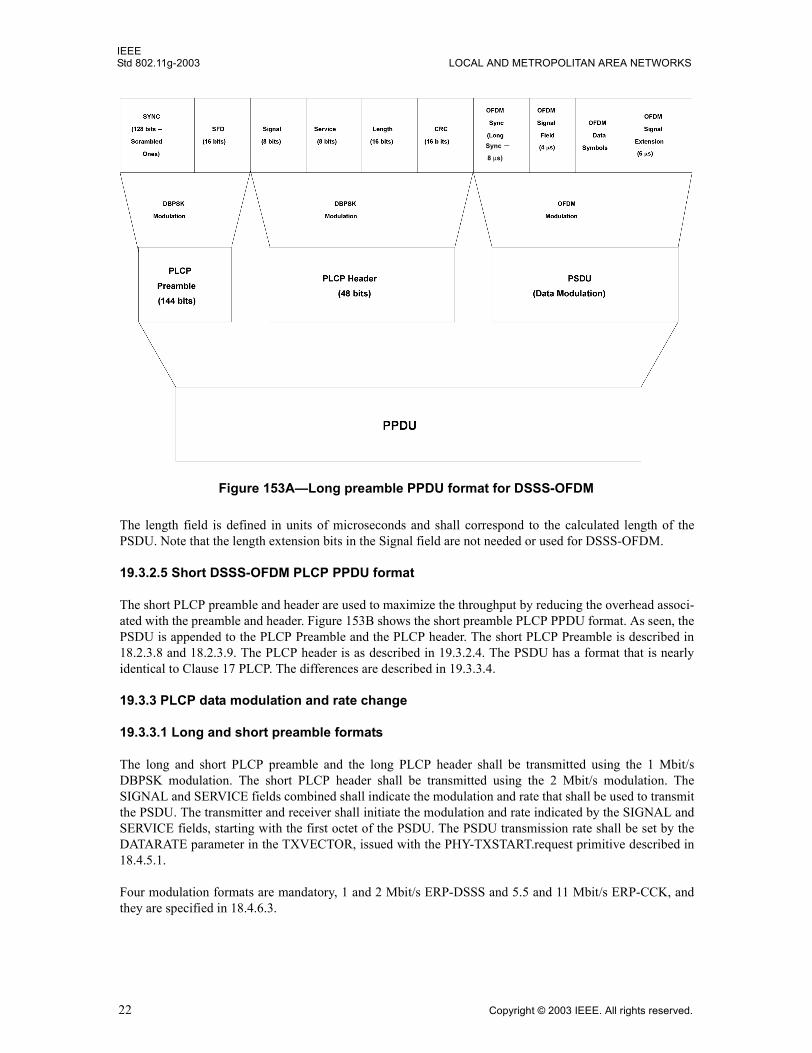
IEEEStd 802.11g-2003 LOCAL AND METROPOLITAN AREA NETWORKS
The length field is defined in units of microseconds and shall correspond to the calculated length of thePSDU. Note that the length extension bits in the Signal field are not needed or used for DSSS-OFDM.
19.3.2.5 Short DSSS-OFDM PLCP PPDU format
The short PLCP preamble and header are used to maximize the throughput by reducing the overhead associ-ated with the preamble and header. Figure 153B shows the short preamble PLCP PPDU format. As seen, thePSDU is appended to the PLCP Preamble and the PLCP header. The short PLCP Preamble is described in18.2.3.8 and 18.2.3.9. The PLCP header is as described in 19.3.2.4. The PSDU has a format that is nearlyidentical to Clause 17 PLCP. The differences are described in 19.3.3.4.
19.3.3 PLCP data modulation and rate change
19.3.3.1 Long and short preamble formats
The long and short PLCP preamble and the long PLCP header shall be transmitted using the 1 Mbit/sDBPSK modulation. The short PLCP header shall be transmitted using the 2 Mbit/s modulation. TheSIGNAL and SERVICE fields combined shall indicate the modulation and rate that shall be used to transmitthe PSDU. The transmitter and receiver shall initiate the modulation and rate indicated by the SIGNAL andSERVICE fields, starting with the first octet of the PSDU. The PSDU transmission rate shall be set by theDATARATE parameter in the TXVECTOR, issued with the PHY-TXSTART.request primitive described in18.4.5.1.
Four modulation formats are mandatory, 1 and 2 Mbit/s ERP-DSSS and 5.5 and 11 Mbit/s ERP-CCK, andthey are specified in 18.4.6.3.
Figure 153A�Long preamble PPDU format for DSSS-OFDM
Sync −8 µs)
22 Copyright © 2003 IEEE. All rights reserved.
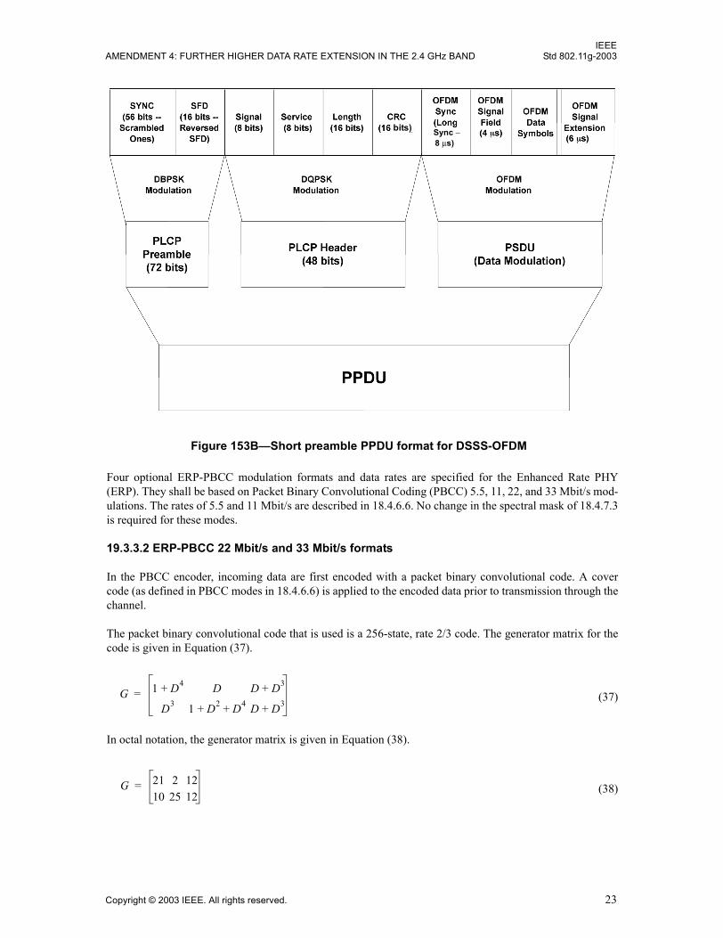
IEEEAMENDMENT 4: FURTHER HIGHER DATA RATE EXTENSION IN THE 2.4 GHz BAND Std 802.11g-2003
Four optional ERP-PBCC modulation formats and data rates are specified for the Enhanced Rate PHY(ERP). They shall be based on Packet Binary Convolutional Coding (PBCC) 5.5, 11, 22, and 33 Mbit/s mod-ulations. The rates of 5.5 and 11 Mbit/s are described in 18.4.6.6. No change in the spectral mask of 18.4.7.3is required for these modes.
19.3.3.2 ERP-PBCC 22 Mbit/s and 33 Mbit/s formats
In the PBCC encoder, incoming data are first encoded with a packet binary convolutional code. A covercode (as defined in PBCC modes in 18.4.6.6) is applied to the encoded data prior to transmission through thechannel.
The packet binary convolutional code that is used is a 256-state, rate 2/3 code. The generator matrix for thecode is given in Equation (37).
(37)
In octal notation, the generator matrix is given in Equation (38).
(38)
Figure 153B�Short preamble PPDU format for DSSS-OFDM
Sync −8 µs)
bits)
G 1 D4+ D D D3+
D3 1 D2 D4+ + D D3+=
G 21 2 1210 25 12
=
Copyright © 2003 IEEE. All rights reserved. 23
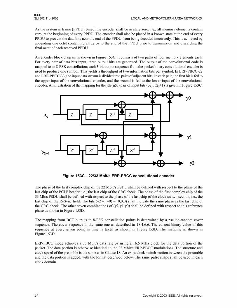
IEEEStd 802.11g-2003 LOCAL AND METROPOLITAN AREA NETWORKS
As the system is frame (PPDU) based, the encoder shall be in state zero; i.e., all memory elements containzero, at the beginning of every PPDU. The encoder shall also be placed in a known state at the end of everyPPDU to prevent the data bits near the end of the PPDU from being decoded incorrectly. This is achieved byappending one octet containing all zeros to the end of the PPDU prior to transmission and discarding thefinal octet of each received PPDU.
An encoder block diagram is shown in Figure 153C. It consists of two paths of four memory elements each.For every pair of data bits input, three output bits are generated. The output of the convolutional code ismapped to an 8-PSK constellation; each 3-bit output sequence from the packet binary convolutional encoder isused to produce one symbol. This yields a throughput of two information bits per symbol. In ERP-PBCC-22and ERP-PBCC-33, the input data stream is divided into pairs of adjacent bits. In each pair, the first bit is fed tothe upper input of the convolutional encoder, and the second is fed to the lower input of the convolutionalencoder. An illustration of the mapping for the jth (j≥0) pair of input bits (b2j, b2j+1) is given in Figure 153C.
The phase of the first complex chip of the 22 Mbit/s PSDU shall be defined with respect to the phase of thelast chip of the PCLP header, i.e., the last chip of the CRC check. The phase of the first complex chip of the33 Mb/s PSDU shall be defined with respect to the phase of the last chip of the clock switch section, i.e., thelast chip of the ReSync field. The bits (y2 y1 y0) = (0,0,0) shall indicate the same phase as the last chip ofthe CRC check. The other seven combinations of (y2 y1 y0) shall be defined with respect to this referencephase as shown in Figure 153D.
The mapping from BCC outputs to 8-PSK constellation points is determined by a pseudo-random coversequence. The cover sequence is the same one as described in 18.4.6.6. The current binary value of thissequence at every given point in time is taken as shown in Figure 153D. The mapping is shown inFigure 153D.
ERP-PBCC mode achieves a 33 Mbit/s data rate by using a 16.5 MHz clock for the data portion of thepacket. The data portion is otherwise identical to the 22 Mbit/s ERP-PBCC modulations. The structure andclock speed of the preamble is the same as in Clause 18. An extra clock switch section between the preambleand the data portion is added, with the format described below. The same pulse shape shall be used in eachclock domain.
Figure 153C�22/33 Mbit/s ERP-PBCC convolutional encoder
Z-1 Z-1 Z-1 Z-1
Z-1 Z-1 Z-1Z-1
y0
y2
y1
b2j
Z-1 Z-1 Z-1 Z-1
Z-1 Z-1 Z-1Z-1
y0
y2
y1
b2j
b2j+1Z-1 Z-1 Z-1 Z-1
Z-1 Z-1 Z-1Z-1
y0
y2
y1
b2j
Z-1 Z-1 Z-1 Z-1
Z-1 Z-1 Z-1Z-1
y0
y2
y1
b2j
b2j+1
24 Copyright © 2003 IEEE. All rights reserved.
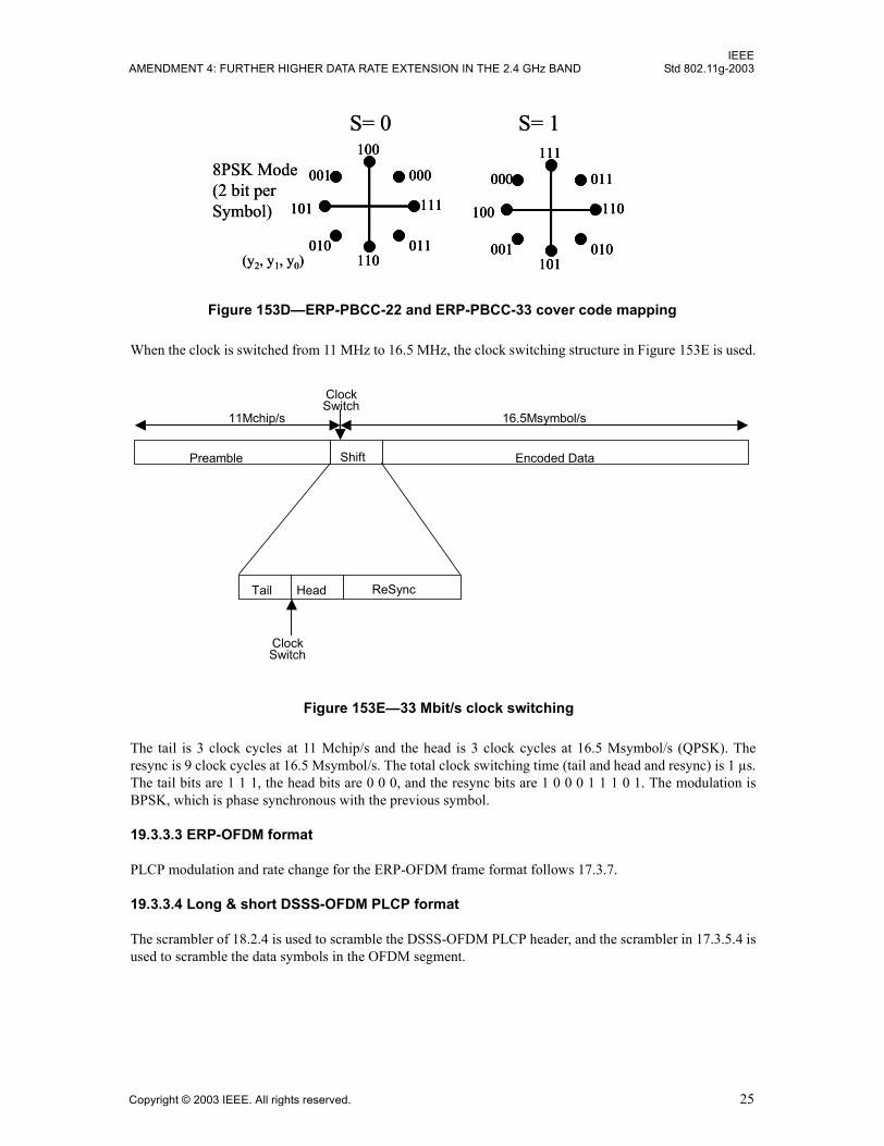
IEEEAMENDMENT 4: FURTHER HIGHER DATA RATE EXTENSION IN THE 2.4 GHz BAND Std 802.11g-2003
When the clock is switched from 11 MHz to 16.5 MHz, the clock switching structure in Figure 153E is used.
The tail is 3 clock cycles at 11 Mchip/s and the head is 3 clock cycles at 16.5 Msymbol/s (QPSK). Theresync is 9 clock cycles at 16.5 Msymbol/s. The total clock switching time (tail and head and resync) is 1 µs.The tail bits are 1 1 1, the head bits are 0 0 0, and the resync bits are 1 0 0 0 1 1 1 0 1. The modulation isBPSK, which is phase synchronous with the previous symbol.
19.3.3.3 ERP-OFDM format
PLCP modulation and rate change for the ERP-OFDM frame format follows 17.3.7.
19.3.3.4 Long & short DSSS-OFDM PLCP format
The scrambler of 18.2.4 is used to scramble the DSSS-OFDM PLCP header, and the scrambler in 17.3.5.4 isused to scramble the data symbols in the OFDM segment.
Figure 153D�ERP-PBCC-22 and ERP-PBCC-33 cover code mapping
101
100
000
110011
111
010
001
S= 0
(y2, y1, y0)
100
111
011
101010
110
001
000
S= 1
8PSK Mode(2 bit perSymbol) 101
100
000
110011
111
010
001
101
100
000
110011
111
010
001
S= 0
(y2, y1, y0)
100
111
011
101010
110
001
000
100
111
011
101010
110
001
000
S= 1
8PSK Mode(2 bit perSymbol)
Preamble Encoded Data
11Mchip/s
Shift
16.5Msymbol/s
Clock Switch
Clock Switch
ReSyncTail Head
Figure 153E�33 Mbit/s clock switching
Copyright © 2003 IEEE. All rights reserved. 25
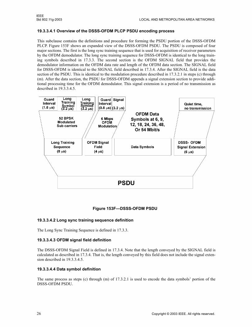
IEEEStd 802.11g-2003 LOCAL AND METROPOLITAN AREA NETWORKS
19.3.3.4.1 Overview of the DSSS-OFDM PLCP PSDU encoding process
This subclause contains the definitions and procedure for forming the PSDU portion of the DSSS-OFDMPLCP. Figure 153F shows an expanded view of the DSSS-OFDM PSDU. The PSDU is composed of fourmajor sections. The first is the long sync training sequence that is used for acquisition of receiver parametersby the OFDM demodulator. The long sync training sequence for DSSS-OFDM is identical to the long train-ing symbols described in 17.3.3. The second section is the OFDM SIGNAL field that provides thedemodulator information on the OFDM data rate and length of the OFDM data section. The SIGNAL fieldfor DSSS-OFDM is identical to the SIGNAL field described in 17.3.4. After the SIGNAL field is the datasection of the PSDU. This is identical to the modulation procedure described in 17.3.2.1 in steps (c) through(m). After the data section, the PSDU for DSSS-OFDM appends a signal extension section to provide addi-tional processing time for the OFDM demodulator. This signal extension is a period of no transmission asdescribed in 19.3.3.4.5.
19.3.3.4.2 Long sync training sequence definition
The Long Sync Training Sequence is defined in 17.3.3.
19.3.3.4.3 OFDM signal field definition
The DSSS-OFDM Signal Field is defined in 17.3.4. Note that the length conveyed by the SIGNAL field iscalculated as described in 17.3.4. That is, the length conveyed by this field does not include the signal exten-sion described in 19.3.3.4.5.
19.3.3.4.4 Data symbol definition
The same process as steps (c) through (m) of 17.3.2.1 is used to encode the data symbols� portion of theDSSS-OFDM PSDU.
Figure 153F�DSSS-OFDM PSDU
26 Copyright © 2003 IEEE. All rights reserved.
IEEEAMENDMENT 4: FURTHER HIGHER DATA RATE EXTENSION IN THE 2.4 GHz BAND Std 802.11g-2003
19.3.3.4.5 DSSS-OFDM signal extension
The DSSS-OFDM Signal Extension shall be a period of no transmission of 6 µs length. It is inserted to allowmore time to finish the convolutional decoding of the OFDM segment waveform and still meet the 10 µsSIFS requirement of the ERP.
19.3.4 PLCP transmit procedure
The transmit procedure will depend on the data rate and modulation format requested. For data rates of 1, 2,5.5, 11, 22, and 33 Mbit/s, the PLCP transmit procedure shall follow 18.2.5. For the ERP_OFDM rates of 6,12, and 24 and the rates of 9, 18, 36, 48, and 54 Mbit/s, the PLCP transmit procedure shall follow 17.3.11.
The transmit procedures for the optional DSSS-OFDM mode using the long or short PLCP preamble andheader are the same as those described in 18.2.5, and they do not change apart from the ability to transmit ahigher rate PSDU using DSSS-OFDM.
19.3.5 CCA
The PLCP shall provide the capability to perform a clear channel assessment (CCA) and report the results ofthe assessment to the MAC. The CCA mechanism shall detect a �medium busy� condition for all supportedpreamble and header types. That is, the CCA mechanism shall detect that the medium is busy for the PLCPPPDUs specified in 17.3.3 and 18.2.2. The CCA mechanism performance requirements are given in 19.4.6.
The ERP shall provide the capability to perform CCA according to the following method:
CCA Mode (ED and CS): A combination of carrier sense (CS) and energy above threshold. CCAshall have a mechanism for carrier sense that will detect all mandatory Clause 19 sync symbols.This CCA�s mode�s carrier sense shall include both Barker code sync detection and OFDM syncsymbol detection. CCA shall report busy at least while a PPDU with energy above the ED thresholdis being received at the antenna.
The energy detection status shall be given by the PMD primitive, PMD_ED. The carrier sense status shall begiven by PMD_CS. The status of PMD_ED and PMD_CS is used in the PLCP convergence procedure toindicate activity to the MAC through the PHY interface primitive, PHY-CCA.indicate. A busy channel shallbe indicated by PHY-CCA.indicate of class BUSY. A clear channel shall be indicated by PHY-CCA.indicateof class IDLE.
19.3.6 PLCP receive procedure
This describes the procedure used by receivers of the ERP. An ERP receiver shall be capable of receiving 1,2, 5.5, and 11 Mbit/s PLCPs using either the long or short preamble formats described in Clause 18 and shallbe capable of receiving 6, 12, and 24 Mbit/s using the modulation and preamble described in Clause 17. ThePHY may also implement the ERP-PBCC modulation at rates of 5.5, 11, 22, and 33 Mbit/s; the ERP-OFDMmodulations at rates of 9, 18, 36, 48, and 54 Mbit/s; and/or the DSSS-OFDM modulation rates of 6, 9, 12,18, 24, 36, 48, and 54 Mbit/s. The receiver shall be capable of detecting the preamble type (ERP-OFDM,Short Preamble, or Long Preamble) and the modulation type. These values shall be reported in theRXVECTOR (see 19.2).
Upon the receipt of a PPDU, the receiver shall first distinguish between the ERP-OFDM preamble and thesingle carrier modulations (long or short preamble). In the case where the preamble is an ERP-OFDMpreamble, the PLCP Receive Procedure shall follow the procedure described in 17.3.12. Otherwise, thereceiver shall then distinguish between the long preamble and short preamble as specified in 18.2.2. Thereceiver shall then demodulate the SERVICE field to determine the modulation type as specified in 19.3.2.1or 19.3.2.2. For short preamble and long preamble using ERP-DSSS, ERP-CCK, or ERP-PBCCmodulations, the receiver shall then follow the receive procedure described in 18.2.6.
Copyright © 2003 IEEE. All rights reserved. 27
IEEEStd 802.11g-2003 LOCAL AND METROPOLITAN AREA NETWORKS
A receiver that supports DSSS-OFDM is capable of receiving all rates specified in Clause 15 and all manda-tory rates in Clause 17 and Clause 18. If the SIGNAL field indicates 3 Mbit/s, the receiver shall attempt toreceive a DSSS-OFDM packet. The remaining receive procedures for a DSSS-OFDM-capable receiver arethe same as those described in 18.2.6, and they do not change apart from the ability to receive DSSS-OFDMin the PSDU. If DSSS-OFDM is being received, the receiver shall handle the modulation transition require-ments as described in 19.7.2. The receiver shall then follow the receive procedure described in 17.3.12.
19.4 ERP PMD operating specifications (general)
Subclauses 19.4.1 through 19.4.7 provide general specifications for the ERP PMD sublayers. These specifi-cations are based on 17.3.8 except where noted.
19.4.1 Regulatory requirements
All systems shall comply with the local regulatory requirements for operation in the 2.4 GHz band. For theUSA, refer to FCC 15.247, 15.249, 15.205, and 15.209. For Europe, refer to ETS 300-328. For Japan, referto MPHPT article 49-20.
19.4.2 Operating channel frequencies
The ERP shall operate in the frequency ranges specified in 18.4.6.2, as allocated by regulatory bodies in theUSA, Europe, and Japan. OFDM operation in channel 14 may not be allowed in Japan. The channel number-ing and the number of operating channels shall follow Table 105 of 18.4.6.2.
19.4.3 Transmit and receive in-band and out-of-band spurious emissions
The ERP shall conform to in-band and out-of-band spurious emissions as set by the appropriate regulatorybodies for the 2.4 GHz band.
19.4.4 Slot time
The slot time is 20 µs, except that an optional 9 µs slot time may be used when the BSS consists of only ERPSTAs capable of supporting this option. The optional 9 µs slot time shall not be used if the network has oneor more non-ERP STAs associated. For IBSS, the Short Slot Time subfield shall be set to 0, corresponding toa 20 µs slot time.
19.4.5 SIFS value
The ERP shall use a SIFS of 10 µs.
19.4.6 CCA performance
The CCA shall indicate TRUE if there is no CCA �medium busy� indication. The CCA parameters are sub-ject to the following criteria:
a) When a valid signal with a signal power of �76 dBm or greater at the receiver antenna connectoris present at the start of the PHY slot, the receiver's CCA indicator shall report the channel busywith probability CCA_Detect_Probabilty within a CCA_Time. CCA_Time is SlotTime �RxTxTurnaroundTime. CCA_Detect_Probabilty is the probability that the CCA does respondcorrectly to a valid signal. The values for these parameters are found in Table 123E. Note that theCCA Detect Probability and the power level are performance requirements.
28 Copyright © 2003 IEEE. All rights reserved.
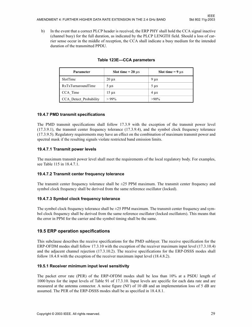
IEEEAMENDMENT 4: FURTHER HIGHER DATA RATE EXTENSION IN THE 2.4 GHz BAND Std 802.11g-2003
b) In the event that a correct PLCP header is received, the ERP PHY shall hold the CCA signal inactive(channel busy) for the full duration, as indicated by the PLCP LENGTH field. Should a loss of car-rier sense occur in the middle of reception, the CCA shall indicate a busy medium for the intendedduration of the transmitted PPDU.
19.4.7 PMD transmit specifications
The PMD transmit specifications shall follow 17.3.9 with the exception of the transmit power level(17.3.9.1), the transmit center frequency tolerance (17.3.9.4), and the symbol clock frequency tolerance(17.3.9.5). Regulatory requirements may have an effect on the combination of maximum transmit power andspectral mask if the resulting signals violate restricted band emission limits.
19.4.7.1 Transmit power levels
The maximum transmit power level shall meet the requirements of the local regulatory body. For examples,see Table 115 in 18.4.7.1.
19.4.7.2 Transmit center frequency tolerance
The transmit center frequency tolerance shall be ±25 PPM maximum. The transmit center frequency andsymbol clock frequency shall be derived from the same reference oscillator (locked).
19.4.7.3 Symbol clock frequency tolerance
The symbol clock frequency tolerance shall be ±25 PPM maximum. The transmit center frequency and sym-bol clock frequency shall be derived from the same reference oscillator (locked oscillators). This means thatthe error in PPM for the carrier and the symbol timing shall be the same.
19.5 ERP operation specifications
This subclause describes the receive specifications for the PMD sublayer. The receive specification for theERP-OFDM modes shall follow 17.3.10 with the exception of the receiver maximum input level (17.3.10.4)and the adjacent channel rejection (17.3.10.2). The receive specifications for the ERP-DSSS modes shallfollow 18.4.8 with the exception of the receiver maximum input level (18.4.8.2).
19.5.1 Receiver minimum input level sensitivity
The packet error rate (PER) of the ERP-OFDM modes shall be less than 10% at a PSDU length of1000 bytes for the input levels of Table 91 of 17.3.10. Input levels are specific for each data rate and aremeasured at the antenna connector. A noise figure (NF) of 10 dB and an implementation loss of 5 dB areassumed. The PER of the ERP-DSSS modes shall be as specified in 18.4.8.1.
Table 123E�CCA parameters
Parameter Slot time = 20 µs Slot time = 9 µs
SlotTime 20 µs 9 µsRxTxTurnaroundTime 5 µs 5 µsCCA_Time 15 µs 4 µsCCA_Detect_Probability > 99% >90%
Copyright © 2003 IEEE. All rights reserved. 29
IEEEStd 802.11g-2003 LOCAL AND METROPOLITAN AREA NETWORKS
19.5.2 Adjacent channel rejection
Adjacent channels at 2.4 GHz are defined to be at ±25 MHz spacing. The adjacent channel rejection shall bemeasured by setting the desired signal's strength 3 dB above the rate-dependent sensitivity specified inTable 91 of 17.3.10 and raising the power of the interfering signal until 10% PER is caused for a PSDUlength of 1000 bytes. The power difference between the interfering and the desired channel is the corre-sponding adjacent channel rejection. The interfering signal in the adjacent channel shall be a conformantOFDM signal, unsynchronized with the signal in the channel under test. For an OFDM PHY, the correspond-ing rejection shall be no less than specified in Table 91 of 17.3.10.
The alternative adjacent channel rejection of Table 91 shall not be required for the ERP.
The adjacent channel rejection of the ERP-DSSS modes shall follow 18.4.8.3.
19.5.3 Receive maximum input level capability
The PER shall be less than 10% at a PSDU length of 1000 bytes for an input level of �20 dBm measured atthe antenna connector for any supported modulation signal or data rate (i.e., 1, 2, 5.5, 6, 9, 11, 12, 18, 22, 24,33, 36, 48, 54 Mbit/s).
19.5.4 Transmit spectral mask
The transmit spectral mask for the ERP-OFDM modes shall follow 17.3.9.2 and is shown in Figure 124therein. The transmit spectral mask for the ERP-DSSS modes shall follow 18.4.7.3 and is shown inFigure 149 therein.
19.6 ERP-PBCC operation specifications
The ERP-PBCC receiver specifications shall follow 18.4.8 except as noted.
These optional modes provide systems the ability to achieve data rates of 22 and 33 Mbit/s in modes that arefully backwards compatible with Clause 15 and Clause 18 BSSs without requiring additional coordination orprotection mechanisms. In addition, the 22 Mbit/s ERP-PBCC mode is spectrally identical to Clause 18BSSs. Four optional ERP-PBCC modulation formats and data rates are specified for the ERP. They shall bebased on Packet Binary Convolutional Coding (PBCC) 5.5, 11, 22, and 33 Mbit/s modulations. The rates of5.5 and 11 Mbit/s are described in 18.4.6.6.
19.6.1 Receiver minimum input level sensitivity
For the 22 Mbit/s ERP-PBCC mode, the frame error ratio shall be less than 8 × 10�2 at a PSDU length of1024 octets for an input level of �76 dBm measured at the antenna connector. For the 33 Mbit/s ERP-PBCCmode, the corresponding input level shall be �74 dBm.
19.6.2 Receiver adjacent channel rejection
The adjacent channel rejection shall be equal to or better than 35 dB, with an FER of 8 × 10�2 using ERP-PBCC modulation and a PSDU length of 1024 octets. The adjacent channel rejection shall be measuredusing the following method. Input an ERP-PBCC modulated signal of the same rate at a level 6 dB greaterthan specified in 19.6.1. In an adjacent channel (25 MHz separation as defined by the channel numbering),input a signal modulated in a similar fashion, which adheres to the transmit mask specified in 18.4.7.3, to alevel 41 dB above the level specified in 19.6.1. The adjacent channel signal shall be derived from a separatesignal source. It shall not be a frequency-shifted version of the reference channel. Under these conditions,the FER shall be no worse than 8 × 10�2.
30 Copyright © 2003 IEEE. All rights reserved.
IEEEAMENDMENT 4: FURTHER HIGHER DATA RATE EXTENSION IN THE 2.4 GHz BAND Std 802.11g-2003
19.7 DSSS-OFDM operation specifications
This optional mode provides systems the ability to use OFDM in a mode that is fully compatible withClause 15 and Clause 18 BSSs without requiring additional coordination. That is, it does not need a protec-tion mechanism. This compatibility requires the use of Clause 18 long and short preambles and inclusion ofa signal extension field to match SIFS spacing of Clause 18 systems. By reusing the Clause 18 preambles,this optional mode ensures that the Clause 18 CCA and short inter-frame spacing interval (SIFS) functionproperly when ERP and NonERP STAs interoperate. When this option is enabled, the same rates shall besupported in both ERP-OFDM and DSSS-OFDM. The DSSS-OFDM PMD transmit and receive specifica-tions shall follow the related ERP-OFDM specifications in 19.5.
19.7.1 Overview
This optional extension of the DSSS system builds on the payload data rates of 1, 2, 5.5, and 11 Mbit/s, asdescribed in Clause 18, to provide 6, 9, 12, 18, 24, 36, 48, and 54 Mbit/s payload data rates while reusing thepreambles (short and long) described by Clause 18. The capability described in this subclause is calledDSSS-OFDM. This optional capability complements the Extended Rate OFDM mode described in Clause19 by combining OFDM modulation with DSSS preambles. As a result, for DSSS-OFDM, the PPDU formatdescribed in 18.2.2 is relatively unchanged. The major change is to the format of the PSDU. The Clause 18single carrier PSDU is replaced by a PSDU that is very similar to the PSDUs described in Clause 17. Thissubclause highlights the differences. In addition, 19.7.2 specifies the radio and physical layer behavior of thetransition from the Barker symbol-modulated preamble and the OFDM-modulated data for PSDU.
19.7.2 Single carrier to multicarrier transition requirements
The spectrum mask for the DSSS-OFDM waveform shall meet the requirements as shown in Figure 124 of17.3.9.6.2.
The single carrier signal segment of the packet shall have a coherent relationship with the multicarrier(OFDM) segment of the packet. All characteristics of the signal shall be transferable from one symbol to thenext, even when transitioning to the OFDM segment. This enables high-performance, coherent receiveroperation across the whole packet. This requirement is no different in nature than that stated in Clause 15,Clause 17, and Clause 18. The distinction being that those clauses use a signaling scheme that is either justsingle carrier or just multicarrier. In contrast, for this mode, both single carrier and multicarrier signaling areused within the context of a single packet.
This section specifies the coherent relationship between the single carrier segment and the OFDM segment,so that the receiver has the opportunity to track through the transition without any forced parameter reacqui-sition. The single carrier preamble and header provide all parametric information required for demodulationof the OFDM segment to within conventional estimation-in-noise accuracy. Although multicarrier sync fea-tures are provided for convenience at OFDM segment onset, if and how to use the multicarrier sync forreacquisition is an implementer's decision. Multicarrier sync is not necessary. The packet is coherentthroughout.
As shown in Figure 153G, the ideal transition would provide a constant carrier frequency and phase, a con-stant power, a constant spectrum, and a constant timing relationship. Constant in this context means that thesame clock crystal that sets the frequencies and timing of each part is the same through the transition. Thisallows the frequency and timing tracking loops to work undisturbed through the transition. The followingsubparagraphs establish the ideal transition characteristics for the transmit signal. An additional paragraphspecifies the required implementation fidelity or accuracy.
Copyright © 2003 IEEE. All rights reserved. 31
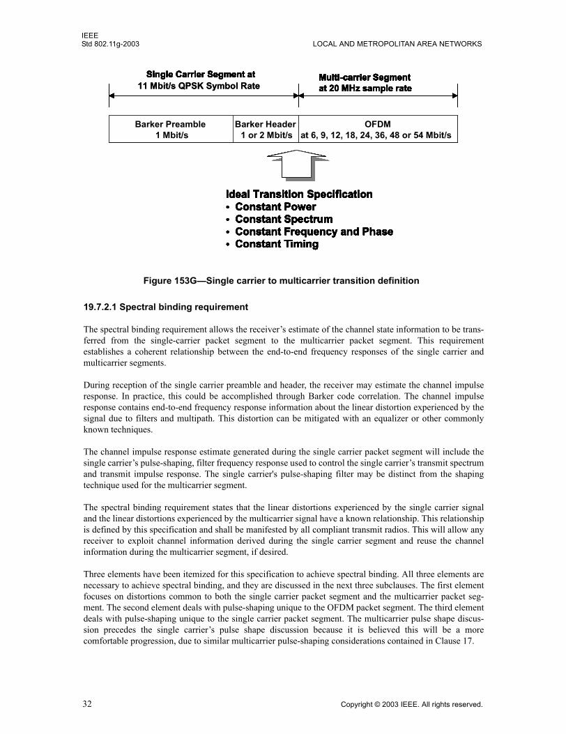
IEEEStd 802.11g-2003 LOCAL AND METROPOLITAN AREA NETWORKS
19.7.2.1 Spectral binding requirement
The spectral binding requirement allows the receiver�s estimate of the channel state information to be trans-ferred from the single-carrier packet segment to the multicarrier packet segment. This requirementestablishes a coherent relationship between the end-to-end frequency responses of the single carrier andmulticarrier segments.
During reception of the single carrier preamble and header, the receiver may estimate the channel impulseresponse. In practice, this could be accomplished through Barker code correlation. The channel impulseresponse contains end-to-end frequency response information about the linear distortion experienced by thesignal due to filters and multipath. This distortion can be mitigated with an equalizer or other commonlyknown techniques.
The channel impulse response estimate generated during the single carrier packet segment will include thesingle carrier�s pulse-shaping, filter frequency response used to control the single carrier�s transmit spectrumand transmit impulse response. The single carrier's pulse-shaping filter may be distinct from the shapingtechnique used for the multicarrier segment.
The spectral binding requirement states that the linear distortions experienced by the single carrier signaland the linear distortions experienced by the multicarrier signal have a known relationship. This relationshipis defined by this specification and shall be manifested by all compliant transmit radios. This will allow anyreceiver to exploit channel information derived during the single carrier segment and reuse the channelinformation during the multicarrier segment, if desired.
Three elements have been itemized for this specification to achieve spectral binding. All three elements arenecessary to achieve spectral binding, and they are discussed in the next three subclauses. The first elementfocuses on distortions common to both the single carrier packet segment and the multicarrier packet seg-ment. The second element deals with pulse-shaping unique to the OFDM packet segment. The third elementdeals with pulse-shaping unique to the single carrier packet segment. The multicarrier pulse shape discus-sion precedes the single carrier�s pulse shape discussion because it is believed this will be a morecomfortable progression, due to similar multicarrier pulse-shaping considerations contained in Clause 17.
Figure 153G�Single carrier to multicarrier transition definition
Barker Preamble1 Mbps
Barker Header1 or 2 Mbps
OFDMat 6, 9, 12, 18, 24, 36, 48 and 54 Mbps
Single Carrier Segment at Multi-carrier Segment
Ideal Transition Specification� Constant Power� Constant Spectrum� Constant Frequency and Phase� Constant Timing
Barker Preamble1 Mbps
Barker Header1 or 2 Mbps
OFDMat 6, 9, 12, 18, 24, 36, 48 and 54 Mbps
Single Carrier Segment at Multi-carrier Segment at 20 MHz sample rate
Ideal Transition Specification� Constant Power� Constant Spectrum� Constant Frequency and Phase� Constant Timing
Barker Preamble1 Mbps
Barker Header1 or 2 Mbps
OFDMat 6, 9, 12, 18, 24, 36, 48 and 54 Mbps
Single Carrier Segment at Multi-carrier Segment
Ideal Transition Specification� Constant Power� Constant Spectrum� Constant Frequency and Phase� Constant Timing
Barker Preamble1 Mbit/s
Barker Header1 or 2 Mbit/s
OFDMat 6, 9, 12, 18, 24, 36, 48 or 54 Mbit/s
Single Carrier Segment at 11 Mbit/s QPSK Symbol Rate
Multi-carrier Segment at 20 MHz sample rate
Ideal Transition Specification� Constant Power� Constant Spectrum� Constant Frequency and Phase� Constant Timing
Barker Preamble1 Mbps
Barker Header1 or 2 Mbps
OFDMat 6, 9, 12, 18, 24, 36, 48 and 54 Mbps
Single Carrier Segment at Multi-carrier Segment
Ideal Transition Specification� Constant Power� Constant Spectrum� Constant Frequency and Phase� Constant Timing
Barker Preamble1 Mbps
Barker Header1 or 2 Mbps
OFDMat 6, 9, 12, 18, 24, 36, 48 and 54 Mbps
Single Carrier Segment at Multi-carrier Segment at 20 MHz sample rate
Ideal Transition Specification� Constant Power� Constant Spectrum� Constant Frequency and Phase� Constant Timing
Barker Preamble1 Mbps
Barker Header1 or 2 Mbps
OFDMat 6, 9, 12, 18, 24, 36, 48 and 54 Mbps
Single Carrier Segment at Multi-carrier Segment
Ideal Transition Specification� Constant Power� Constant Spectrum� Constant Frequency and Phase� Constant Timing
Barker Preamble1 Mbit/s
Barker Header1 or 2 Mbit/s
OFDMat 6, 9, 12, 18, 24, 36, 48 or 54 Mbit/s
Single Carrier Segment at 11 Mbit/s QPSK Symbol Rate
Multi-carrier Segment at 20 MHz sample rate
Ideal Transition Specification� Constant Power� Constant Spectrum� Constant Frequency and Phase� Constant Timing
Multi-carrier Segment at 20 MHz sample rate
Ideal Transition Specification� Constant Power� Constant Spectrum� Constant Frequency and Phase� Constant Timing
32 Copyright © 2003 IEEE. All rights reserved.
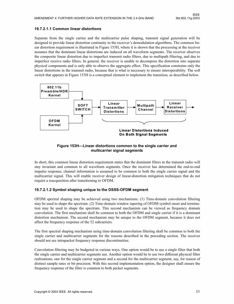
IEEEAMENDMENT 4: FURTHER HIGHER DATA RATE EXTENSION IN THE 2.4 GHz BAND Std 802.11g-2003
19.7.2.1.1 Common linear distortions
Separate from the single carrier and the multicarrier pulse shaping, transmit signal generation will bedesigned to provide linear distortion continuity to the receiver�s demodulation algorithms. The common lin-ear distortion requirement is illustrated in Figure 153H, where it is shown that the processing at the receiverassumes that the dominant linear distortions are induced on all waveform segments. The receiver observesthe composite linear distortion due to imperfect transmit radio filters, due to multipath filtering, and due toimperfect receive radio filters. In general, the receiver is unable to decompose the distortion into separatephysical components and is only able to observe the aggregate effect. This specification constrains only thelinear distortions in the transmit radio, because that is what is necessary to ensure interoperability. The softswitch that appears in Figure 153H is a conceptual element to implement the transition, as described below.
In short, this common linear distortion requirement states that the dominant filters in the transmit radio willstay invariant and common to all waveform segments. Once the receiver has determined the end-to-endimpulse response, channel information is assumed to be common to both the single carrier signal and themulticarrier signal. This will enable receiver design of linear-distortion mitigation techniques that do notrequire a reacquisition after transitioning to OFDM.
19.7.2.1.2 Symbol shaping unique to the DSSS-OFDM segment
OFDM spectral shaping may be achieved using two mechanisms: (1) Time-domain convolution filteringmay be used to shape the spectrum. (2) Time-domain window tapering of OFDM symbol onset and termina-tion may be used to shape the spectrum. This second mechanism can be viewed as frequency domainconvolution. The first mechanism shall be common to both the OFDM and single carrier if it is a dominantdistortion mechanism. The second mechanism may be unique to the OFDM segment, because it does notaffect the frequency response of the 52 subcarriers.
The first spectral shaping mechanism using time-domain convolution filtering shall be common to both thesingle carrier and multicarrier segments for the reasons described in the preceding section. The receivershould not see intrapacket frequency response discontinuities.
Convolution filtering may be budgeted in various ways. One option would be to use a single filter that boththe single carrier and multicarrier segments use. Another option would be to use two different physical filterrealizations, one for the single carrier segment and a second for the multicarrier segment, say, for reason ofdistinct sample rates or bit precision. With this second implementation option, the designer shall ensure thefrequency response of the filter is common to both packet segments.
Figure 153H�Linear distortions common to the single carrier and multicarrier signal segments
802.11bPream ble/HDR
Kernel
OFDMKernel
SOFTSW ITCH
LinearTransm itterDistortions
M ultipathChannel
LinearReceiver
Distortions
Linear Distortions InducedOn Both Signal Segm ents
802.11bPream ble/HDR
Kernel
OFDMKernel
SOFTSW ITCH
LinearTransm itterDistortions
M ultipathChannel
LinearReceiver
Distortions
Linear Distortions InducedOn Both Signal Segm ents
Copyright © 2003 IEEE. All rights reserved. 33
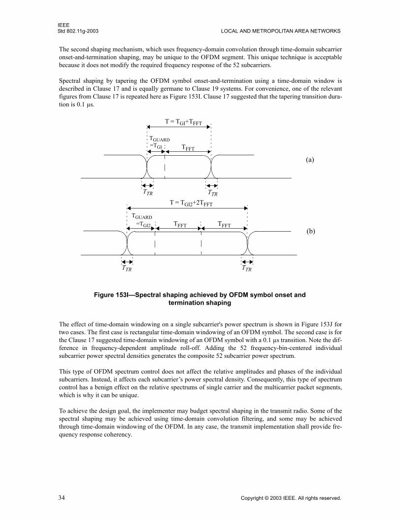
IEEEStd 802.11g-2003 LOCAL AND METROPOLITAN AREA NETWORKS
The second shaping mechanism, which uses frequency-domain convolution through time-domain subcarrieronset-and-termination shaping, may be unique to the OFDM segment. This unique technique is acceptablebecause it does not modify the required frequency response of the 52 subcarriers.
Spectral shaping by tapering the OFDM symbol onset-and-termination using a time-domain window isdescribed in Clause 17 and is equally germane to Clause 19 systems. For convenience, one of the relevantfigures from Clause 17 is repeated here as Figure 153I. Clause 17 suggested that the tapering transition dura-tion is 0.1 µs.
The effect of time-domain windowing on a single subcarrier's power spectrum is shown in Figure 153J fortwo cases. The first case is rectangular time-domain windowing of an OFDM symbol. The second case is forthe Clause 17 suggested time-domain windowing of an OFDM symbol with a 0.1 µs transition. Note the dif-ference in frequency-dependent amplitude roll-off. Adding the 52 frequency-bin-centered individualsubcarrier power spectral densities generates the composite 52 subcarrier power spectrum.
This type of OFDM spectrum control does not affect the relative amplitudes and phases of the individualsubcarriers. Instead, it affects each subcarrier�s power spectral density. Consequently, this type of spectrumcontrol has a benign effect on the relative spectrums of single carrier and the multicarrier packet segments,which is why it can be unique.
To achieve the design goal, the implementer may budget spectral shaping in the transmit radio. Some of thespectral shaping may be achieved using time-domain convolution filtering, and some may be achievedthrough time-domain windowing of the OFDM. In any case, the transmit implementation shall provide fre-quency response coherency.
TTR TTR
TTR TTR
T = TGI+TFFT
TGUARD
TFFT
T = TGI2+2TFFT
TFFT TFFT=TGI2
(a)
(b)
=TGI
TGUARD
Figure 153I�Spectral shaping achieved by OFDM symbol onset and termination shaping
34 Copyright © 2003 IEEE. All rights reserved.
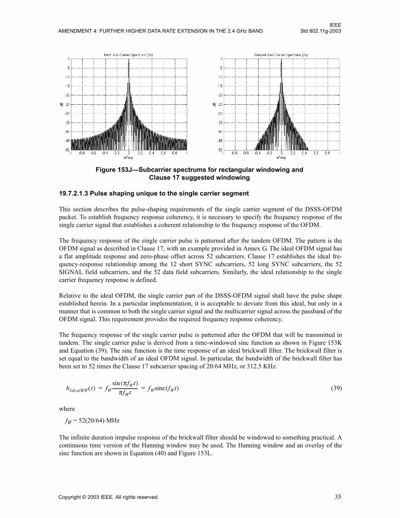
IEEEAMENDMENT 4: FURTHER HIGHER DATA RATE EXTENSION IN THE 2.4 GHz BAND Std 802.11g-2003
19.7.2.1.3 Pulse shaping unique to the single carrier segment
This section describes the pulse-shaping requirements of the single carrier segment of the DSSS-OFDMpacket. To establish frequency response coherency, it is necessary to specify the frequency response of thesingle carrier signal that establishes a coherent relationship to the frequency response of the OFDM.
The frequency response of the single carrier pulse is patterned after the tandem OFDM. The pattern is theOFDM signal as described in Clause 17, with an example provided in Annex G. The ideal OFDM signal hasa flat amplitude response and zero-phase offset across 52 subcarriers. Clause 17 establishes the ideal fre-quency-response relationship among the 12 short SYNC subcarriers, 52 long SYNC subcarriers, the 52SIGNAL field subcarriers, and the 52 data field subcarriers. Similarly, the ideal relationship to the singlecarrier frequency response is defined.
Relative to the ideal OFDM, the single carrier part of the DSSS-OFDM signal shall have the pulse shapeestablished herein. In a particular implementation, it is acceptable to deviate from this ideal, but only in amanner that is common to both the single carrier signal and the multicarrier signal across the passband of theOFDM signal. This requirement provides the required frequency response coherency.
The frequency response of the single carrier pulse is patterned after the OFDM that will be transmitted intandem. The single carrier pulse is derived from a time-windowed sinc function as shown in Figure 153Kand Equation (39). The sinc function is the time response of an ideal brickwall filter. The brickwall filter isset equal to the bandwidth of an ideal OFDM signal. In particular, the bandwidth of the brickwall filter hasbeen set to 52 times the Clause 17 subcarrier spacing of 20/64 MHz, or 312.5 KHz.
(39)
where
fW = 52(20/64) MHz
The infinite duration impulse response of the brickwall filter should be windowed to something practical. Acontinuous time version of the Hanning window may be used. The Hanning window and an overlay of thesinc function are shown in Equation (40) and Figure 153L.
Figure 153J�Subcarrier spectrums for rectangular windowing and Clause 17 suggested windowing
hIdealBW t( ) fWπfWt( )sin
πfWt----------------------- fWsinc fWt( )= =
Copyright © 2003 IEEE. All rights reserved. 35
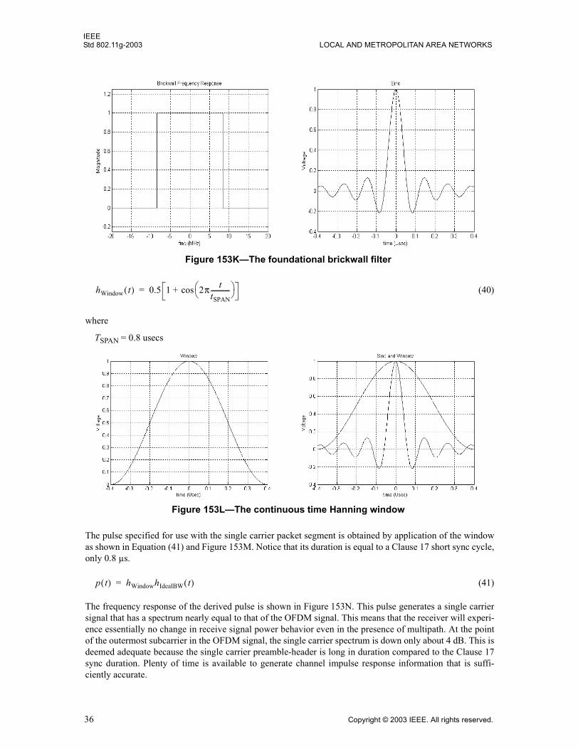
IEEEStd 802.11g-2003 LOCAL AND METROPOLITAN AREA NETWORKS
(40)
where
TSPAN = 0.8 usecs
The pulse specified for use with the single carrier packet segment is obtained by application of the windowas shown in Equation (41) and Figure 153M. Notice that its duration is equal to a Clause 17 short sync cycle,only 0.8 µs.
(41)
The frequency response of the derived pulse is shown in Figure 153N. This pulse generates a single carriersignal that has a spectrum nearly equal to that of the OFDM signal. This means that the receiver will experi-ence essentially no change in receive signal power behavior even in the presence of multipath. At the pointof the outermost subcarrier in the OFDM signal, the single carrier spectrum is down only about 4 dB. This isdeemed adequate because the single carrier preamble-header is long in duration compared to the Clause 17sync duration. Plenty of time is available to generate channel impulse response information that is suffi-ciently accurate.
Figure 153K�The foundational brickwall filter
hWindow t( ) 0.5 1 2π ttSPAN------------
cos+=
Figure 153L�The continuous time Hanning window
p t( ) hWindowhIdealBW t( )=
36 Copyright © 2003 IEEE. All rights reserved.
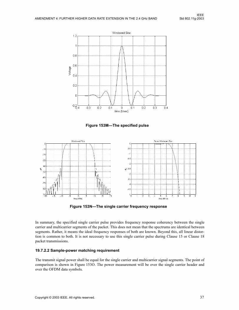
IEEEAMENDMENT 4: FURTHER HIGHER DATA RATE EXTENSION IN THE 2.4 GHz BAND Std 802.11g-2003
In summary, the specified single carrier pulse provides frequency response coherency between the singlecarrier and multicarrier segments of the packet. This does not mean that the spectrums are identical betweensegments. Rather, it means the ideal frequency responses of both are known. Beyond this, all linear distor-tion is common to both. It is not necessary to use this single carrier pulse during Clause 15 or Clause 18packet transmissions.
19.7.2.2 Sample-power matching requirement
The transmit signal power shall be equal for the single carrier and multicarrier signal segments. The point ofcomparison is shown in Figure 153O. The power measurement will be over the single carrier header andover the OFDM data symbols.
Figure 153M�The specified pulse
Figure 153N�The single carrier frequency response
Copyright © 2003 IEEE. All rights reserved. 37
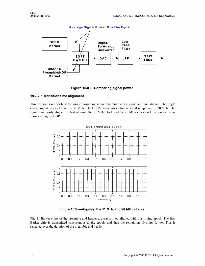
IEEEStd 802.11g-2003 LOCAL AND METROPOLITAN AREA NETWORKS
19.7.2.3 Transition time alignment
This section describes how the single carrier signal and the multicarrier signal are time aligned. The singlecarrier signal uses a chip rate of 11 MHz. The OFDM signal uses a fundamental sample rate of 20 MHz. Thesignals are easily aligned by first aligning the 11 MHz clock and the 20 MHz clock on 1 µs boundaries asshown in Figure 153P.
The 11 Barker chips of the preamble and header are transmitted aligned with this timing epoch. The firstBarker chip is transmitted synchronous to the epoch, and then the remaining 10 chips follow. This isrepeated over the duration of the preamble and header.
Figure 153O�Comparing signal power
802.11bPream ble/HDR
Kernel
OFDMKernel
SOFTSW ITCH D AC
DigitalTo AnalogConverter
LPF SAWFilter
LowPassFilter
Average Signal Pow er M ust be Equal
802.11bPream ble/HDR
Kernel
OFDMKernel
SOFTSW ITCH D AC
DigitalTo AnalogConverter
LPF SAWFilter
LowPassFilter
Average Signal Pow er M ust be Equal
Figure 153P�Aligning the 11 MHz and 20 MHz clocks
38 Copyright © 2003 IEEE. All rights reserved.
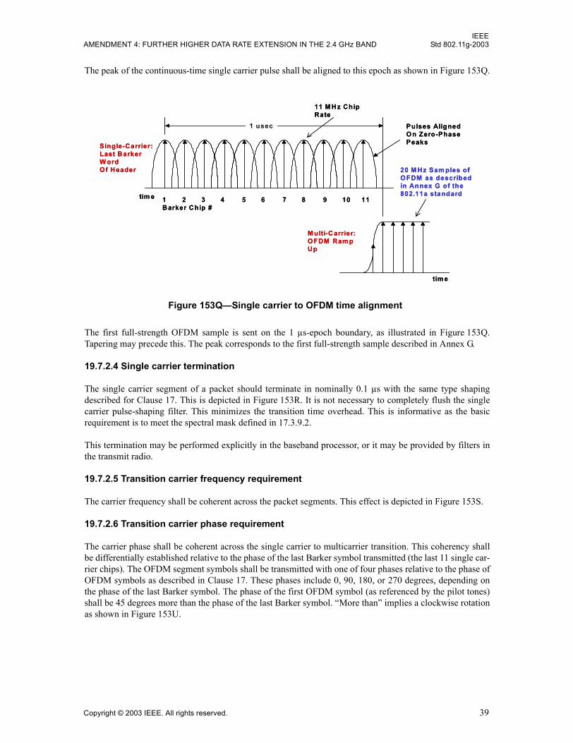
IEEEAMENDMENT 4: FURTHER HIGHER DATA RATE EXTENSION IN THE 2.4 GHz BAND Std 802.11g-2003
The peak of the continuous-time single carrier pulse shall be aligned to this epoch as shown in Figure 153Q.
The first full-strength OFDM sample is sent on the 1 µs-epoch boundary, as illustrated in Figure 153Q.Tapering may precede this. The peak corresponds to the first full-strength sample described in Annex G.
19.7.2.4 Single carrier termination
The single carrier segment of a packet should terminate in nominally 0.1 µs with the same type shapingdescribed for Clause 17. This is depicted in Figure 153R. It is not necessary to completely flush the singlecarrier pulse-shaping filter. This minimizes the transition time overhead. This is informative as the basicrequirement is to meet the spectral mask defined in 17.3.9.2.
This termination may be performed explicitly in the baseband processor, or it may be provided by filters inthe transmit radio.
19.7.2.5 Transition carrier frequency requirement
The carrier frequency shall be coherent across the packet segments. This effect is depicted in Figure 153S.
19.7.2.6 Transition carrier phase requirement
The carrier phase shall be coherent across the single carrier to multicarrier transition. This coherency shallbe differentially established relative to the phase of the last Barker symbol transmitted (the last 11 single car-rier chips). The OFDM segment symbols shall be transmitted with one of four phases relative to the phase ofOFDM symbols as described in Clause 17. These phases include 0, 90, 180, or 270 degrees, depending onthe phase of the last Barker symbol. The phase of the first OFDM symbol (as referenced by the pilot tones)shall be 45 degrees more than the phase of the last Barker symbol. �More than� implies a clockwise rotationas shown in Figure 153U.
Figure 153Q�Single carrier to OFDM time alignment
1 2 3 4 5 6 7 8 9 10 11Barker Chip #
1 usec
Single-Carrier:Last BarkerW ordOf Header
Pulses AlignedO n Zero-PhasePeaks
M ulti-Carrier:OFDM Ram pUp
tim e
tim e
20 M Hz Sam ples ofOFDM as described in Annex G of the 802.11a standard
11 M Hz ChipRate
1 2 3 4 5 6 7 8 9 10 11Barker Chip #
1 usec
Single-Carrier:Last BarkerW ordOf Header
Pulses AlignedO n Zero-PhasePeaks
M ulti-Carrier:OFDM Ram pUp
tim e
tim e
20 M Hz Sam ples ofOFDM as described in Annex G of the 802.11a standard
11 M Hz ChipRate
Copyright © 2003 IEEE. All rights reserved. 39
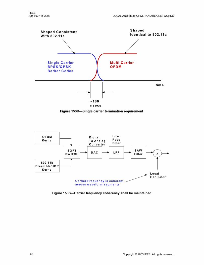
IEEEStd 802.11g-2003 LOCAL AND METROPOLITAN AREA NETWORKS
Figure 153R�Single carrier termination requirement
Single CarrierBPSK/QPSKBarker Codes
M ulti-CarrierOFDM
tim e
ShapedIdentical to 802.11a
Shaped Consistent W ith 802.11a
~100nsecs
Figure 153S�Carrier frequency coherency shall be maintained
802.11bPream ble/HDR
Kernel
OFDMKernel
SOFTSW ITCH D AC
DigitalTo AnalogConverter
LPF SAWFilter
LowPassFilter
Carrier Frequency is coherentacross w aveform segm ents
x
LocalOscillator
40 Copyright © 2003 IEEE. All rights reserved.
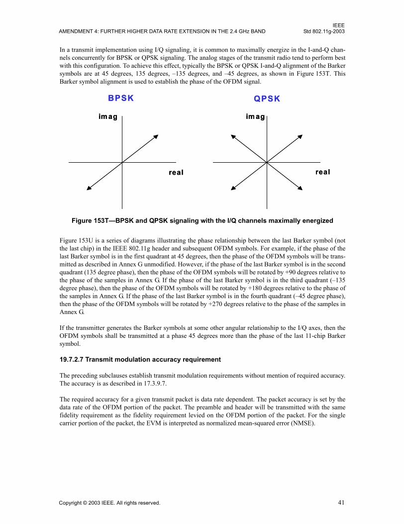
IEEEAMENDMENT 4: FURTHER HIGHER DATA RATE EXTENSION IN THE 2.4 GHz BAND Std 802.11g-2003
In a transmit implementation using I/Q signaling, it is common to maximally energize in the I-and-Q chan-nels concurrently for BPSK or QPSK signaling. The analog stages of the transmit radio tend to perform bestwith this configuration. To achieve this effect, typically the BPSK or QPSK I-and-Q alignment of the Barkersymbols are at 45 degrees, 135 degrees, �135 degrees, and �45 degrees, as shown in Figure 153T. ThisBarker symbol alignment is used to establish the phase of the OFDM signal.
Figure 153U is a series of diagrams illustrating the phase relationship between the last Barker symbol (notthe last chip) in the IEEE 802.11g header and subsequent OFDM symbols. For example, if the phase of thelast Barker symbol is in the first quadrant at 45 degrees, then the phase of the OFDM symbols will be trans-mitted as described in Annex G unmodified. However, if the phase of the last Barker symbol is in the secondquadrant (135 degree phase), then the phase of the OFDM symbols will be rotated by +90 degrees relative tothe phase of the samples in Annex G. If the phase of the last Barker symbol is in the third quadrant (�135degree phase), then the phase of the OFDM symbols will be rotated by +180 degrees relative to the phase ofthe samples in Annex G. If the phase of the last Barker symbol is in the fourth quadrant (�45 degree phase),then the phase of the OFDM symbols will be rotated by +270 degrees relative to the phase of the samples inAnnex G.
If the transmitter generates the Barker symbols at some other angular relationship to the I/Q axes, then theOFDM symbols shall be transmitted at a phase 45 degrees more than the phase of the last 11-chip Barkersymbol.
19.7.2.7 Transmit modulation accuracy requirement
The preceding subclauses establish transmit modulation requirements without mention of required accuracy.The accuracy is as described in 17.3.9.7.
The required accuracy for a given transmit packet is data rate dependent. The packet accuracy is set by thedata rate of the OFDM portion of the packet. The preamble and header will be transmitted with the samefidelity requirement as the fidelity requirement levied on the OFDM portion of the packet. For the singlecarrier portion of the packet, the EVM is interpreted as normalized mean-squared error (NMSE).
Figure 153T�BPSK and QPSK signaling with the I/Q channels maximally energized
real real
im agim ag
BPSK QPSK
real real
im agim ag
BPSK QPSK
Copyright © 2003 IEEE. All rights reserved. 41
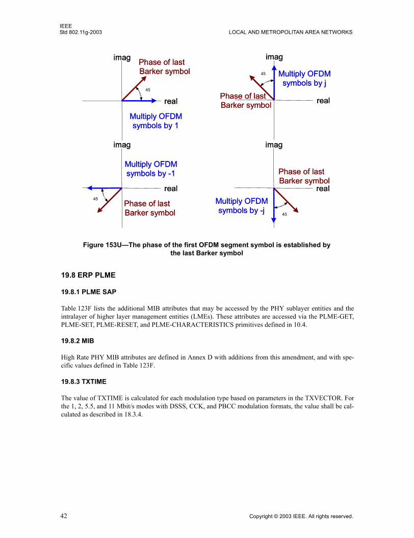
IEEEStd 802.11g-2003 LOCAL AND METROPOLITAN AREA NETWORKS
19.8 ERP PLME
19.8.1 PLME SAP
Table 123F lists the additional MIB attributes that may be accessed by the PHY sublayer entities and theintralayer of higher layer management entities (LMEs). These attributes are accessed via the PLME-GET,PLME-SET, PLME-RESET, and PLME-CHARACTERISTICS primitives defined in 10.4.
19.8.2 MIB
High Rate PHY MIB attributes are defined in Annex D with additions from this amendment, and with spe-cific values defined in Table 123F.
19.8.3 TXTIME
The value of TXTIME is calculated for each modulation type based on parameters in the TXVECTOR. Forthe 1, 2, 5.5, and 11 Mbit/s modes with DSSS, CCK, and PBCC modulation formats, the value shall be cal-culated as described in 18.3.4.
Figure 153U�The phase of the first OFDM segment symbol is established by the last Barker symbol
45
real
imag Phase of lastBarker symbol
Multiply OFDMsymbols by 1
45
real
imag
Phase of lastBarker symbol
Multiply OFDMsymbols by j
45
real
imag
Phase of lastBarker symbol
Multiply OFDMsymbols by -j
45
real
imag
Phase of lastBarker symbol
Multiply OFDMsymbols by -1
45
real
imag Phase of lastBarker symbol
Multiply OFDMsymbols by 1
45
real
imag
Phase of lastBarker symbol
Multiply OFDMsymbols by j
45
real
imag
Phase of lastBarker symbol
Multiply OFDMsymbols by -j
45
real
imag
Phase of lastBarker symbol
Multiply OFDMsymbols by -1
42 Copyright © 2003 IEEE. All rights reserved.
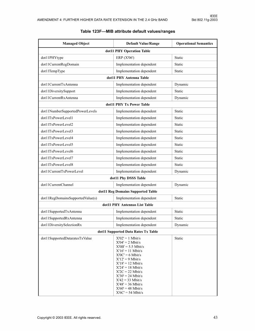
IEEEAMENDMENT 4: FURTHER HIGHER DATA RATE EXTENSION IN THE 2.4 GHz BAND Std 802.11g-2003
Table 123F�MIB attribute default values/ranges
Managed Object Default Value/Range Operational Semantics
dot11 PHY Operation Table
dot11PHYtype ERP (X'06') Static
dot11CurrentRegDomain Implementation dependent Static
dot11TempType Implementation dependent Static
dot11 PHY Antenna Table
dot11CurrentTxAntenna Implementation dependent Dynamic
dot11DiversitySupport Implementation dependent Static
dot11CurrentRxAntenna Implementation dependent Dynamic
dot11 PHY Tx Power Table
dot11NumberSupportedPowerLevels Implementation dependent Static
dot11TxPowerLevel1 Implementation dependent Static
dot11TxPowerLevel2 Implementation dependent Static
dot11TxPowerLevel3 Implementation dependent Static
dot11TxPowerLevel4 Implementation dependent Static
dot11TxPowerLevel5 Implementation dependent Static
dot11TxPowerLevel6 Implementation dependent Static
dot11TxPowerLevel7 Implementation dependent Static
dot11TxPowerLevel8 Implementation dependent Static
dot11CurrentTxPowerLevel Implementation dependent Dynamic
dot11 Phy DSSS Table
dot11CurrentChannel Implementation dependent Dynamic
dot11 Reg Domains Supported Table
dot11RegDomainsSupportedValue(s) Implementation dependent Static
dot11 PHY Antennas List Table
dot11SupportedTxAntenna Implementation dependent Static
dot11SupportedRxAntenna Implementation dependent Static
dot11DiversitySelectionRx Implementation dependent Dynamic
dot11 Supported Data Rates Tx Table
dot11SupportedDataratesTxValue X'02' = 1 Mbit/sX'04' = 2 Mbit/s X'0B' = 5.5 Mbit/sX'16' = 11 Mbit/sX'0C' = 6 Mbit/sX'12' = 9 Mbit/sX'18' = 12 Mbit/sX'24' = 18 Mbit/sX'2C = 22 Mbit/sX'30' = 24 Mbit/sX'42 = 33 Mbit/sX'48' = 36 Mbit/sX'60' = 48 Mbit/sX'6C' = 54 Mbit/s
Static
Copyright © 2003 IEEE. All rights reserved. 43
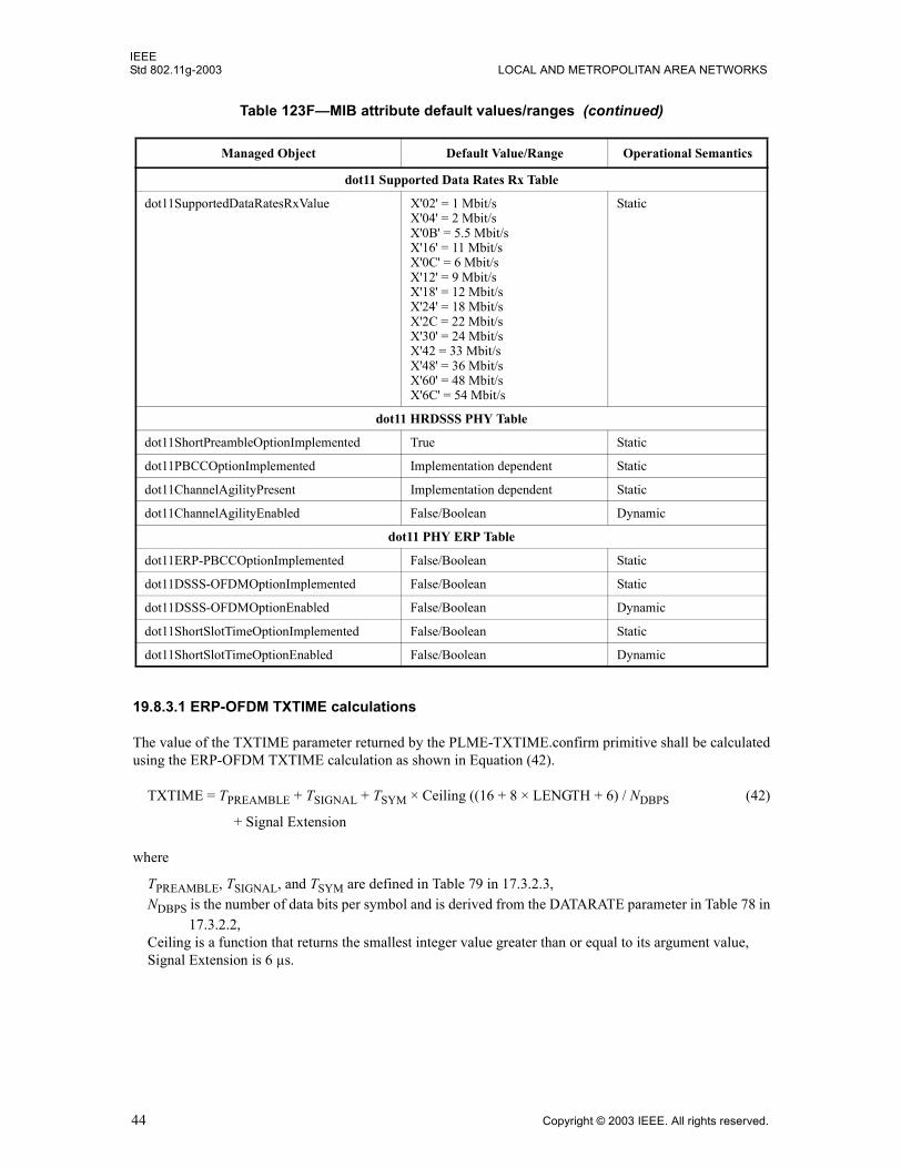
IEEEStd 802.11g-2003 LOCAL AND METROPOLITAN AREA NETWORKS
19.8.3.1 ERP-OFDM TXTIME calculations
The value of the TXTIME parameter returned by the PLME-TXTIME.confirm primitive shall be calculatedusing the ERP-OFDM TXTIME calculation as shown in Equation (42).
TXTIME = TPREAMBLE + TSIGNAL + TSYM × Ceiling ((16 + 8 × LENGTH + 6) / NDBPS (42)
+ Signal Extension
where
TPREAMBLE, TSIGNAL, and TSYM are defined in Table 79 in 17.3.2.3,NDBPS is the number of data bits per symbol and is derived from the DATARATE parameter in Table 78 in
17.3.2.2,Ceiling is a function that returns the smallest integer value greater than or equal to its argument value,Signal Extension is 6 µs.
dot11 Supported Data Rates Rx Table
dot11SupportedDataRatesRxValue X'02' = 1 Mbit/sX'04' = 2 Mbit/s X'0B' = 5.5 Mbit/sX'16' = 11 Mbit/sX'0C' = 6 Mbit/sX'12' = 9 Mbit/sX'18' = 12 Mbit/sX'24' = 18 Mbit/sX'2C = 22 Mbit/sX'30' = 24 Mbit/sX'42 = 33 Mbit/sX'48' = 36 Mbit/sX'60' = 48 Mbit/sX'6C' = 54 Mbit/s
Static
dot11 HRDSSS PHY Table
dot11ShortPreambleOptionImplemented True Static
dot11PBCCOptionImplemented Implementation dependent Static
dot11ChannelAgilityPresent Implementation dependent Static
dot11ChannelAgilityEnabled False/Boolean Dynamic
dot11 PHY ERP Table
dot11ERP-PBCCOptionImplemented False/Boolean Static
dot11DSSS-OFDMOptionImplemented False/Boolean Static
dot11DSSS-OFDMOptionEnabled False/Boolean Dynamic
dot11ShortSlotTimeOptionImplemented False/Boolean Static
dot11ShortSlotTimeOptionEnabled False/Boolean Dynamic
Table 123F�MIB attribute default values/ranges (continued)
Managed Object Default Value/Range Operational Semantics
44 Copyright © 2003 IEEE. All rights reserved.
IEEEAMENDMENT 4: FURTHER HIGHER DATA RATE EXTENSION IN THE 2.4 GHz BAND Std 802.11g-2003
19.8.3.2 ERP-PBCC TXTIME calculations
The value of the TXTIME parameter returned by the PLME-TXTIME.confirm primitive shall be calculatedaccording to the following:
For PBCC 5.5 and 11 Mbit/s, see 18.3.4.
For ERP-PBCC-22 Mbit/s, use Equation (43).
TXTIME = PreambleLength + PLCPHeaderTime + Ceiling(((LENGTH+PBCC) × 8) / DATARATE) (43)
For ERP-PBCC-33 Mbit/s, use Equation (44).
TXTIME = PreambleLength + PLCPHeaderTime
+ Ceiling(((LENGTH+PBCC) × 8) / DATARATE) + ClkSwitchTime. (44)
where
LENGTH and DATARATE are values from the TXVECTOR parameter of the corresponding PLME-TXTIME request primitive,
�PBCC� has a value of 1 if the SIGNAL value from the TXVECTOR parameter specifies ERP-PBCC andhas a value of 0 otherwise,
PreambleLength is 144 µs if the PREAMBLE_TYPE value from the TXVECTOR parameter indicates�LONGPREAMBLE� or 72 µs if the PREAMBLE_TYPE value from the TXVECTOR parameterindicates �SHORTPREAMBLE�,
PLCPHeaderTime is 48 µs if the PREAMBLE_TYPE value from the TXVECTOR parameter indicates�LONGPREAMBLE� or 24 µs if the PREAMBLE_TYPE value from the TXVECTOR parameterindicates �SHORTPREAMBLE�,
LENGTH is in units of octets,DATARATE is in units of Mbit/s,ClkSwitchTime is defined as 1 µs,Ceiling is a function that returns the smallest integer value greater than or equal to its argument value.
19.8.3.3 DSSS-OFDM TXTIME calculations
The value of the TXTIME parameter returned by the PLME-TXTIME.confirm primitive shall be calculatedaccording to Equation (45):
TXTIME = PreambleLengthDSSS + PLCPHeaderTimeDSSS (45)+ PreambleLengthOFDM + PLCPSignalOFDM
+ 4 × Ceiling((PLCPServiceBits + 8 × (NumberOfOctets) + PadBits) / NDBPS) + SignalExtension
where
PreambleLengthDSSS is 144 µs if the PREAMBLE_TYPE value from the TXVECTOR parameter indi-cates �LONGPREAMBLE,� or 72 µs if the PREAMBLE_TYPE value from the TXVECTORparameter indicates �SHORTPREAMBLE�,
PLCPHeaderTimeDSSS is 48 µs if the PREAMBLE_TYPE value from the TXVECTOR parameter indi-cates �LONGPREAMBLE,� or 24 µs if the PREAMBLE_TYPE value from the TXVECTORparameter indicates �SHORTPREAMBLE�,
Ceiling is a function that returns the smallest integer value greater than or equal to its argument value;PreambleLengthOFDM is 8 µs,PLCPSignalOFDM is 4 µs,PLCPServiceBits is 16 bits;
Copyright © 2003 IEEE. All rights reserved. 45
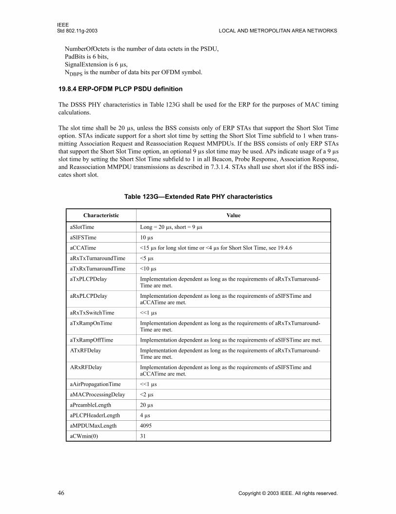
IEEEStd 802.11g-2003 LOCAL AND METROPOLITAN AREA NETWORKS
NumberOfOctets is the number of data octets in the PSDU,PadBits is 6 bits,SignalExtension is 6 µs,NDBPS is the number of data bits per OFDM symbol.
19.8.4 ERP-OFDM PLCP PSDU definition
The DSSS PHY characteristics in Table 123G shall be used for the ERP for the purposes of MAC timingcalculations.
The slot time shall be 20 µs, unless the BSS consists only of ERP STAs that support the Short Slot Timeoption. STAs indicate support for a short slot time by setting the Short Slot Time subfield to 1 when trans-mitting Association Request and Reassociation Request MMPDUs. If the BSS consists of only ERP STAsthat support the Short Slot Time option, an optional 9 µs slot time may be used. APs indicate usage of a 9 µsslot time by setting the Short Slot Time subfield to 1 in all Beacon, Probe Response, Association Response,and Reassociation MMPDU transmissions as described in 7.3.1.4. STAs shall use short slot if the BSS indi-cates short slot.
Table 123G�Extended Rate PHY characteristics
Characteristic Value
aSlotTime Long = 20 µs, short = 9 µs
aSIFSTime 10 µs
aCCATime <15 µs for long slot time or <4 µs for Short Slot Time, see 19.4.6
aRxTxTurnaroundTime <5 µs
aTxRxTurnaroundTime <10 µs
aTxPLCPDelay Implementation dependent as long as the requirements of aRxTxTurnaround-Time are met.
aRxPLCPDelay Implementation dependent as long as the requirements of aSIFSTime and aCCATime are met.
aRxTxSwitchTime <<1 µs
aTxRampOnTime Implementation dependent as long as the requirements of aRxTxTurnaround-Time are met.
aTxRampOffTime Implementation dependent as long as the requirements of aSIFSTime are met.
ATxRFDelay Implementation dependent as long as the requirements of aRxTxTurnaround-Time are met.
ARxRFDelay Implementation dependent as long as the requirements of aSIFSTime and aCCATime are met.
aAirPropagationTime <<1 µs
aMACProcessingDelay <2 µs
aPreambleLength 20 µs
aPLCPHeaderLength 4 µs
aMPDUMaxLength 4095
aCWmin(0) 31
46 Copyright © 2003 IEEE. All rights reserved.
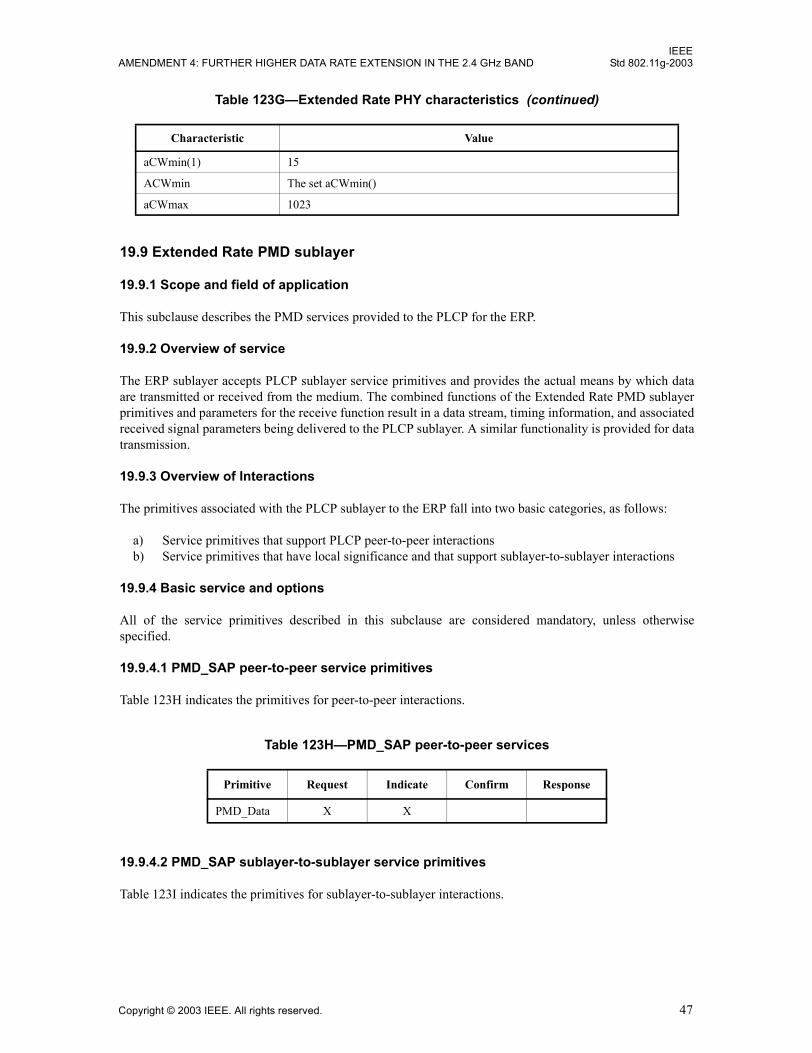
IEEEAMENDMENT 4: FURTHER HIGHER DATA RATE EXTENSION IN THE 2.4 GHz BAND Std 802.11g-2003
19.9 Extended Rate PMD sublayer
19.9.1 Scope and field of application
This subclause describes the PMD services provided to the PLCP for the ERP.
19.9.2 Overview of service
The ERP sublayer accepts PLCP sublayer service primitives and provides the actual means by which dataare transmitted or received from the medium. The combined functions of the Extended Rate PMD sublayerprimitives and parameters for the receive function result in a data stream, timing information, and associatedreceived signal parameters being delivered to the PLCP sublayer. A similar functionality is provided for datatransmission.
19.9.3 Overview of Interactions
The primitives associated with the PLCP sublayer to the ERP fall into two basic categories, as follows:
a) Service primitives that support PLCP peer-to-peer interactionsb) Service primitives that have local significance and that support sublayer-to-sublayer interactions
19.9.4 Basic service and options
All of the service primitives described in this subclause are considered mandatory, unless otherwisespecified.
19.9.4.1 PMD_SAP peer-to-peer service primitives
Table 123H indicates the primitives for peer-to-peer interactions.
19.9.4.2 PMD_SAP sublayer-to-sublayer service primitives
Table 123I indicates the primitives for sublayer-to-sublayer interactions.
aCWmin(1) 15
ACWmin The set aCWmin()
aCWmax 1023
Table 123H�PMD_SAP peer-to-peer services
Primitive Request Indicate Confirm Response
PMD_Data X X
Table 123G�Extended Rate PHY characteristics (continued)
Characteristic Value
Copyright © 2003 IEEE. All rights reserved. 47
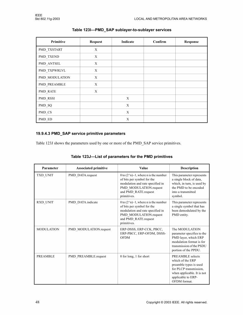
IEEEStd 802.11g-2003 LOCAL AND METROPOLITAN AREA NETWORKS
19.9.4.3 PMD_SAP service primitive parameters
Table 123J shows the parameters used by one or more of the PMD_SAP service primitives.
Table 123I�PMD_SAP sublayer-to-sublayer services
Primitive Request Indicate Confirm Response
PMD_TXSTART X
PMD_TXEND X
PMD_ANTSEL X
PMD_TXPWRLVL X
PMD_MODULATION X
PMD_PREAMBLE X
PMD_RATE X
PMD_RSSI X
PMD_SQ X
PMD_CS X
PMD_ED X
Table 123J�List of parameters for the PMD primitives
Parameter Associated primitive Value Description
TXD_UNIT PMD_DATA.request 0 to (2^n)�1, where n is the number of bits per symbol for the modulation and rate specified in PMD_MODULATION.request and PMD_RATE.request primitives.
This parameter represents a single block of data, which, in turn, is used by the PMD to be encoded into a transmitted symbol.
RXD_UNIT PMD_DATA.indicate 0 to (2^n)�1, where n is the number of bits per symbol for the modulation and rate specified in PMD_MODULATION.request and PMD_RATE.request primitives.
This parameter represents a single symbol that has been demodulated by the PMD entity.
MODULATION PMD_MODULATION.request ERP-DSSS, ERP-CCK, PBCC, ERP-PBCC, ERP-OFDM, DSSS-OFDM
The MODULATION parameter specifies to the PMD layer, which ERP modulation format is for transmission of the PSDU portion of the PPDU.
PREAMBLE PMD_PREAMBLE.request 0 for long, 1 for short PREAMBLE selects which of the ERP preamble types is used for PLCP transmission, when applicable. It is not applicable to ERP-OFDM format.
48 Copyright © 2003 IEEE. All rights reserved.
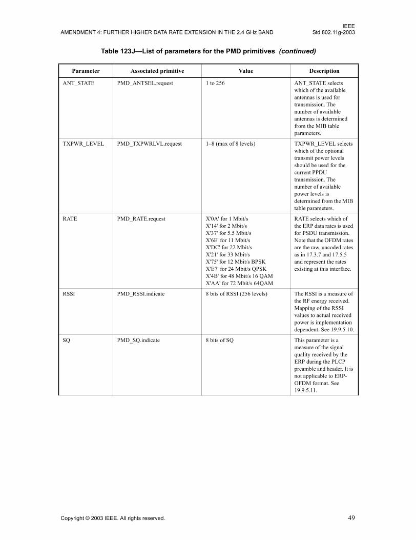
IEEEAMENDMENT 4: FURTHER HIGHER DATA RATE EXTENSION IN THE 2.4 GHz BAND Std 802.11g-2003
ANT_STATE PMD_ANTSEL.request 1 to 256 ANT_STATE selects which of the available antennas is used for transmission. The number of available antennas is determined from the MIB table parameters.
TXPWR_LEVEL PMD_TXPWRLVL.request 1�8 (max of 8 levels) TXPWR_LEVEL selects which of the optional transmit power levels should be used for the current PPDU transmission. The number of available power levels is determined from the MIB table parameters.
RATE PMD_RATE.request X'0A' for 1 Mbit/sX'14' for 2 Mbit/sX'37' for 5.5 Mbit/sX'6E' for 11 Mbit/sX'DC' for 22 Mbit/sX'21' for 33 Mbit/sX'75' for 12 Mbit/s BPSKX'E7' for 24 Mbit/s QPSKX'4B' for 48 Mbit/s 16 QAMX'AA' for 72 Mbit/s 64QAM
RATE selects which of the ERP data rates is used for PSDU transmission. Note that the OFDM rates are the raw, uncoded rates as in 17.3.7 and 17.5.5 and represent the rates existing at this interface.
RSSI PMD_RSSI.indicate 8 bits of RSSI (256 levels) The RSSI is a measure of the RF energy received. Mapping of the RSSI values to actual received power is implementation dependent. See 19.9.5.10.
SQ PMD_SQ.indicate 8 bits of SQ This parameter is a measure of the signal quality received by the ERP during the PLCP preamble and header. It is not applicable to ERP-OFDM format. See 19.9.5.11.
Table 123J�List of parameters for the PMD primitives (continued)
Parameter Associated primitive Value Description
Copyright © 2003 IEEE. All rights reserved. 49
IEEEStd 802.11g-2003 LOCAL AND METROPOLITAN AREA NETWORKS
19.9.5 PMD_SAP detailed service specification
The following subclauses describe the services provided by each PMD primitive.
19.9.5.1 PMD_DATA.request
This primitive is the same as that defined in 17.5.5.1 and 18.4.5.1 except that the parameter TXD_UNIT isexpanded in scope to reflect the supported modulation formats of ERP as defined in 19.9.4.3.
19.9.5.2 PMD_DATA.indicate
This primitive is the same as that defined in 17.5.5.2 and 18.4.5.2 except that the parameter RXD_UNIT isexpanded in scope to reflect the supported modulation formats of ERP as defined in 19.9.4.3.
19.9.5.3 PMD_MODULATION.request
This primitive is the same as that defined in 18.4.5.3 except that the parameter MODULATION is expandedin scope to reflect the supported modulation formats of ERP as defined in 19.9.4.3.
CS PMD_CS.indicate 0 for DISABLED1 for ENABLED The PMD_CS (preamble detect) primitive in conjunction with the PMD_ED provides the CCA status through the PLCP layer PHY?CCA primitive. PMD_CS indicates a binary status of ENABLED or DISABLED. PMD_CS is ENABLED upon detection of Barker code or OFDM sync signals. PMD_CS is DISABLED otherwise.
ED PMD_ED.indicate 0 for DISABLED1 for ENABLED The PMD_ED (energy detect) primitive, along with the PMD_SQ, provides CCA status at the PLCP layer through the PHY?CCA primitive. PMD_ED indicates a binary status of ENABLED or DISABLED. PMD_ED is ENABLED when the RSSI indicated in the PMD_RSSI is greater than the detection threshold. PMD_ED is DISALBED otherwise.
Table 123J�List of parameters for the PMD primitives (continued)
Parameter Associated primitive Value Description
50 Copyright © 2003 IEEE. All rights reserved.
IEEEAMENDMENT 4: FURTHER HIGHER DATA RATE EXTENSION IN THE 2.4 GHz BAND Std 802.11g-2003
19.9.5.4 PMD_PREAMBLE.request
This primitive is the same as that defined in 18.4.5.4, including the definition of the parameter PREAMBLE.This primitive is not used in association with transmission of ERP-OFDM modulations.
19.9.5.5 PMD_TXSTART.request
This primitive is the same as that defined in 17.5.5.3 and 18.4.5.6.
19.9.5.6 PMD_TXEND.request
This primitive is the same as that defined in 17.5.5.4 and 18.4.5.7.
19.9.5.7 PMD_ANTSEL.request
This primitive is the same as that defined in 18.4.5.8, including the definition of the parameterANT_STATE.
19.9.5.8 PMD_TXPRWLVL.request
This primitive is the same as that defined in 17.5.5.5, including the definition of the parameterTXPWR_LEVEL.
19.9.5.9 PMD_RATE.request
This primitive is the same as that defined in 17.5.5.6 and 18.4.5.10, except that the parameter RATE isexpanded in scope to reflect the supported ERP transmission rates as defined in 19.9.4.3.
19.9.5.10 PMD_RSSI.indicate
This primitive is the same as that defined in 17.5.5.7 and 18.4.5.11, including the parameter RSSI. Thisprimitive is used to aid in link optimization algorithms such as roaming decisions.
19.9.5.11 PMD_SQ.indicate
This primitive is the same as that defined in 18.4.5.12, including the parameter SQ. This primitive is notused in association with reception of ERP-OFDM modulations. This primitive is used to aid in link optimi-zation algorithms such as roaming decisions.
19.9.5.12 PMD_CS.indicate
This primitive is the same as that defined in 18.4.5.13, except that its use is expanded for use with all ERPmodulation types as described in 19.3.5.
19.9.5.13 PMD_ED.indicate
This primitive is the same as that defined in 18.4.5.14, except that its use is expanded for use with all ERPmodulation types as described in 19.3.5.
Copyright © 2003 IEEE. All rights reserved. 51
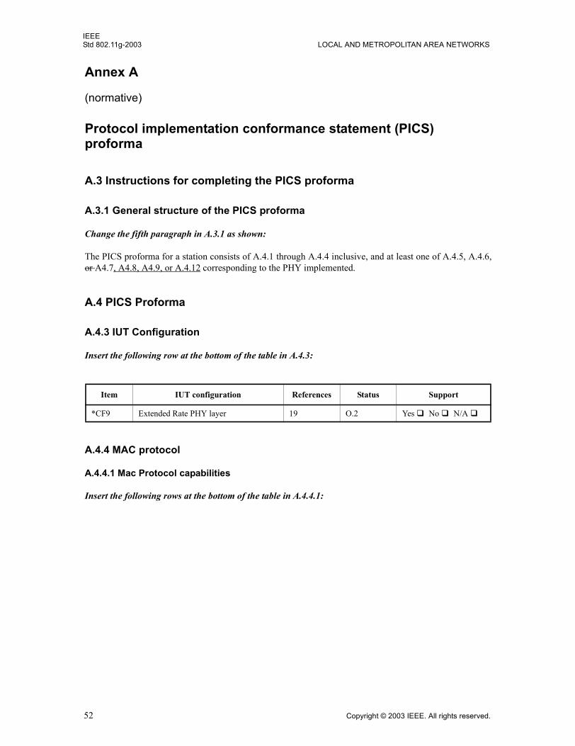
IEEEStd 802.11g-2003 LOCAL AND METROPOLITAN AREA NETWORKS
Annex A
(normative)
Protocol implementation conformance statement (PICS)proforma
A.3 Instructions for completing the PICS proforma
A.3.1 General structure of the PICS proforma
Change the fifth paragraph in A.3.1 as shown:
The PICS proforma for a station consists of A.4.1 through A.4.4 inclusive, and at least one of A.4.5, A.4.6,or A4.7, A4.8, A4.9, or A.4.12 corresponding to the PHY implemented.
A.4 PICS Proforma
A.4.3 IUT Configuration
Insert the following row at the bottom of the table in A.4.3:
A.4.4 MAC protocol
A.4.4.1 Mac Protocol capabilities
Insert the following rows at the bottom of the table in A.4.4.1:
Item IUT configuration References Status Support
*CF9 Extended Rate PHY layer 19 O.2 Yes ! No ! N/A !
52 Copyright © 2003 IEEE. All rights reserved.
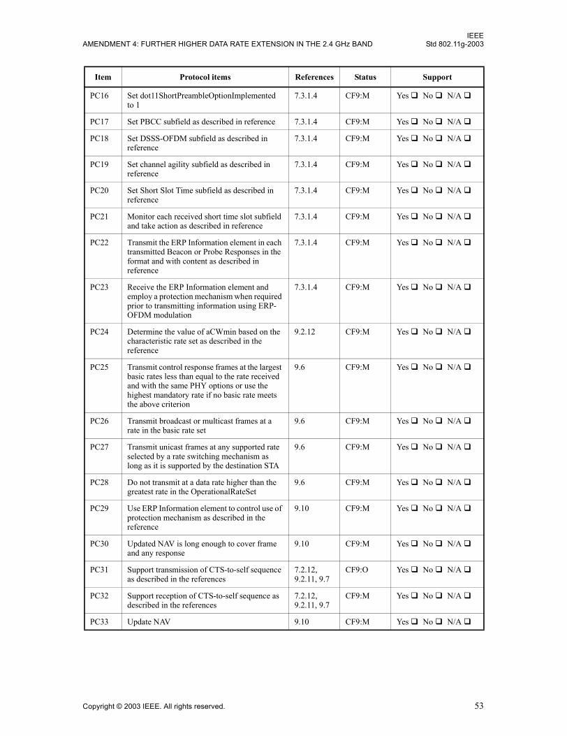
IEEEAMENDMENT 4: FURTHER HIGHER DATA RATE EXTENSION IN THE 2.4 GHz BAND Std 802.11g-2003
Item Protocol items References Status Support
PC16 Set dot11ShortPreambleOptionImplemented to 1
7.3.1.4 CF9:M Yes ! No ! N/A !
PC17 Set PBCC subfield as described in reference 7.3.1.4 CF9:M Yes ! No ! N/A !
PC18 Set DSSS-OFDM subfield as described in reference
7.3.1.4 CF9:M Yes ! No ! N/A !
PC19 Set channel agility subfield as described in reference
7.3.1.4 CF9:M Yes ! No ! N/A !
PC20 Set Short Slot Time subfield as described in reference
7.3.1.4 CF9:M Yes ! No ! N/A !
PC21 Monitor each received short time slot subfield and take action as described in reference
7.3.1.4 CF9:M Yes ! No ! N/A !
PC22 Transmit the ERP Information element in each transmitted Beacon or Probe Responses in the format and with content as described in reference
7.3.1.4 CF9:M Yes ! No ! N/A !
PC23 Receive the ERP Information element and employ a protection mechanism when required prior to transmitting information using ERP-OFDM modulation
7.3.1.4 CF9:M Yes ! No ! N/A !
PC24 Determine the value of aCWmin based on the characteristic rate set as described in the reference
9.2.12 CF9:M Yes ! No ! N/A !
PC25 Transmit control response frames at the largest basic rates less than equal to the rate received and with the same PHY options or use the highest mandatory rate if no basic rate meets the above criterion
9.6 CF9:M Yes ! No ! N/A !
PC26 Transmit broadcast or multicast frames at a rate in the basic rate set
9.6 CF9:M Yes ! No ! N/A !
PC27 Transmit unicast frames at any supported rate selected by a rate switching mechanism as long as it is supported by the destination STA
9.6 CF9:M Yes ! No ! N/A !
PC28 Do not transmit at a data rate higher than the greatest rate in the OperationalRateSet
9.6 CF9:M Yes ! No ! N/A !
PC29 Use ERP Information element to control use of protection mechanism as described in the reference
9.10 CF9:M Yes ! No ! N/A !
PC30 Updated NAV is long enough to cover frame and any response
9.10 CF9:M Yes ! No ! N/A !
PC31 Support transmission of CTS-to-self sequence as described in the references
7.2.12, 9.2.11, 9.7
CF9:O Yes ! No ! N/A !
PC32 Support reception of CTS-to-self sequence as described in the references
7.2.12, 9.2.11, 9.7
CF9:M Yes ! No ! N/A !
PC33 Update NAV 9.10 CF9:M Yes ! No ! N/A !
Copyright © 2003 IEEE. All rights reserved. 53
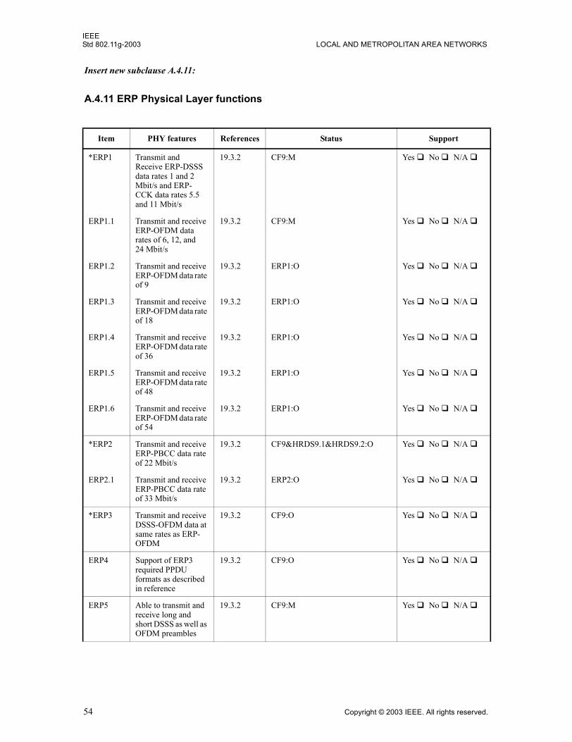
IEEEStd 802.11g-2003 LOCAL AND METROPOLITAN AREA NETWORKS
Insert new subclause A.4.11:
A.4.11 ERP Physical Layer functions
Item PHY features References Status Support
*ERP1 Transmit and Receive ERP-DSSS data rates 1 and 2 Mbit/s and ERP-CCK data rates 5.5 and 11 Mbit/s
19.3.2 CF9:M Yes ! No ! N/A !
ERP1.1 Transmit and receive ERP-OFDM data rates of 6, 12, and 24 Mbit/s
19.3.2 CF9:M Yes ! No ! N/A !
ERP1.2 Transmit and receive ERP-OFDM data rate of 9
19.3.2 ERP1:O Yes ! No ! N/A !
ERP1.3 Transmit and receive ERP-OFDM data rate of 18
19.3.2 ERP1:O Yes ! No ! N/A !
ERP1.4 Transmit and receive ERP-OFDM data rate of 36
19.3.2 ERP1:O Yes ! No ! N/A !
ERP1.5 Transmit and receive ERP-OFDM data rate of 48
19.3.2 ERP1:O Yes ! No ! N/A !
ERP1.6 Transmit and receive ERP-OFDM data rate of 54
19.3.2 ERP1:O Yes ! No ! N/A !
*ERP2 Transmit and receive ERP-PBCC data rate of 22 Mbit/s
19.3.2 CF9&HRDS9.1&HRDS9.2:O Yes ! No ! N/A !
ERP2.1 Transmit and receive ERP-PBCC data rate of 33 Mbit/s
19.3.2 ERP2:O Yes ! No ! N/A !
*ERP3 Transmit and receive DSSS-OFDM data at same rates as ERP-OFDM
19.3.2 CF9:O Yes ! No ! N/A !
ERP4 Support of ERP3 required PPDU formats as described in reference
19.3.2 CF9:O Yes ! No ! N/A !
ERP5 Able to transmit and receive long and short DSSS as well as OFDM preambles
19.3.2 CF9:M Yes ! No ! N/A !
54 Copyright © 2003 IEEE. All rights reserved.
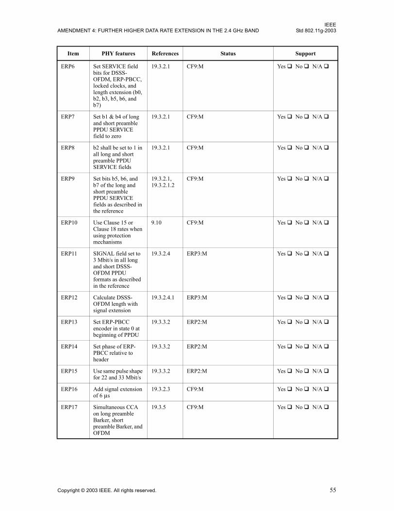
IEEEAMENDMENT 4: FURTHER HIGHER DATA RATE EXTENSION IN THE 2.4 GHz BAND Std 802.11g-2003
ERP6 Set SERVICE field bits for DSSS-OFDM, ERP-PBCC, locked clocks, and length extension (b0, b2, b3, b5, b6, and b7)
19.3.2.1 CF9:M Yes ! No ! N/A !
ERP7 Set b1 & b4 of long and short preamble PPDU SERVICE field to zero
19.3.2.1 CF9:M Yes ! No ! N/A !
ERP8 b2 shall be set to 1 in all long and short preamble PPDU SERVICE fields
19.3.2.1 CF9:M Yes ! No ! N/A !
ERP9 Set bits b5, b6, and b7 of the long and short preamble PPDU SERVICE fields as described in the reference
19.3.2.1, 19.3.2.1.2
CF9:M Yes ! No ! N/A !
ERP10 Use Clause 15 or Clause 18 rates when using protection mechanisms
9.10 CF9:M Yes ! No ! N/A !
ERP11 SIGNAL field set to 3 Mbit/s in all long and short DSSS-OFDM PPDU formats as described in the reference
19.3.2.4 ERP3:M Yes ! No ! N/A !
ERP12 Calculate DSSS-OFDM length with signal extension
19.3.2.4.1 ERP3:M Yes ! No ! N/A !
ERP13 Set ERP-PBCC encoder in state 0 at beginning of PPDU
19.3.3.2 ERP2:M Yes ! No ! N/A !
ERP14 Set phase of ERP-PBCC relative to header
19.3.3.2 ERP2:M Yes ! No ! N/A !
ERP15 Use same pulse shape for 22 and 33 Mbit/s
19.3.3.2 ERP2:M Yes ! No ! N/A !
ERP16 Add signal extension of 6 µs
19.3.2.3 CF9:M Yes ! No ! N/A !
ERP17 Simultaneous CCA on long preamble Barker, short preamble Barker, and OFDM
19.3.5 CF9:M Yes ! No ! N/A !
Item PHY features References Status Support
Copyright © 2003 IEEE. All rights reserved. 55
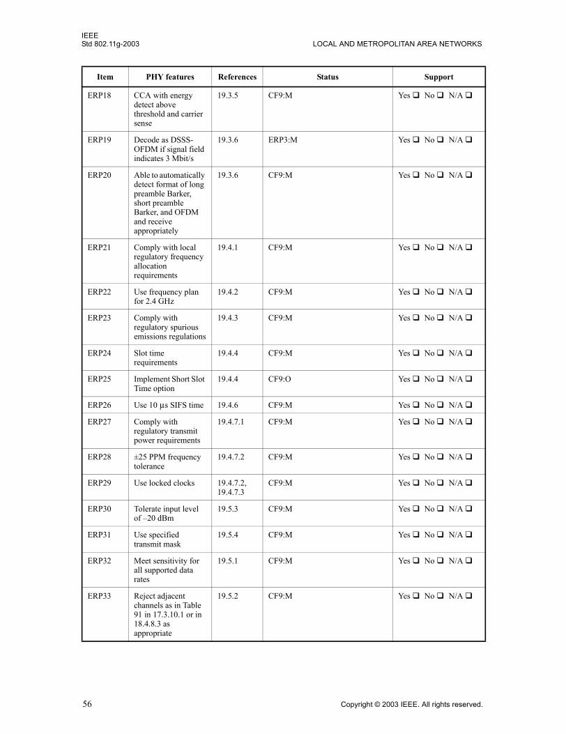
IEEEStd 802.11g-2003 LOCAL AND METROPOLITAN AREA NETWORKS
ERP18 CCA with energy detect above threshold and carrier sense
19.3.5 CF9:M Yes ! No ! N/A !
ERP19 Decode as DSSS-OFDM if signal field indicates 3 Mbit/s
19.3.6 ERP3:M Yes ! No ! N/A !
ERP20 Able to automatically detect format of long preamble Barker, short preamble Barker, and OFDM and receive appropriately
19.3.6 CF9:M Yes ! No ! N/A !
ERP21 Comply with local regulatory frequency allocation requirements
19.4.1 CF9:M Yes ! No ! N/A !
ERP22 Use frequency plan for 2.4 GHz
19.4.2 CF9:M Yes ! No ! N/A !
ERP23 Comply with regulatory spurious emissions regulations
19.4.3 CF9:M Yes ! No ! N/A !
ERP24 Slot time requirements
19.4.4 CF9:M Yes ! No ! N/A !
ERP25 Implement Short Slot Time option
19.4.4 CF9:O Yes ! No ! N/A !
ERP26 Use 10 µs SIFS time 19.4.6 CF9:M Yes ! No ! N/A !
ERP27 Comply with regulatory transmit power requirements
19.4.7.1 CF9:M Yes ! No ! N/A !
ERP28 ±25 PPM frequency tolerance
19.4.7.2 CF9:M Yes ! No ! N/A !
ERP29 Use locked clocks 19.4.7.2, 19.4.7.3
CF9:M Yes ! No ! N/A !
ERP30 Tolerate input level of �20 dBm
19.5.3 CF9:M Yes ! No ! N/A !
ERP31 Use specified transmit mask
19.5.4 CF9:M Yes ! No ! N/A !
ERP32 Meet sensitivity for all supported data rates
19.5.1 CF9:M Yes ! No ! N/A !
ERP33 Reject adjacent channels as in Table 91 in 17.3.10.1 or in 18.4.8.3 as appropriate
19.5.2 CF9:M Yes ! No ! N/A !
Item PHY features References Status Support
56 Copyright © 2003 IEEE. All rights reserved.
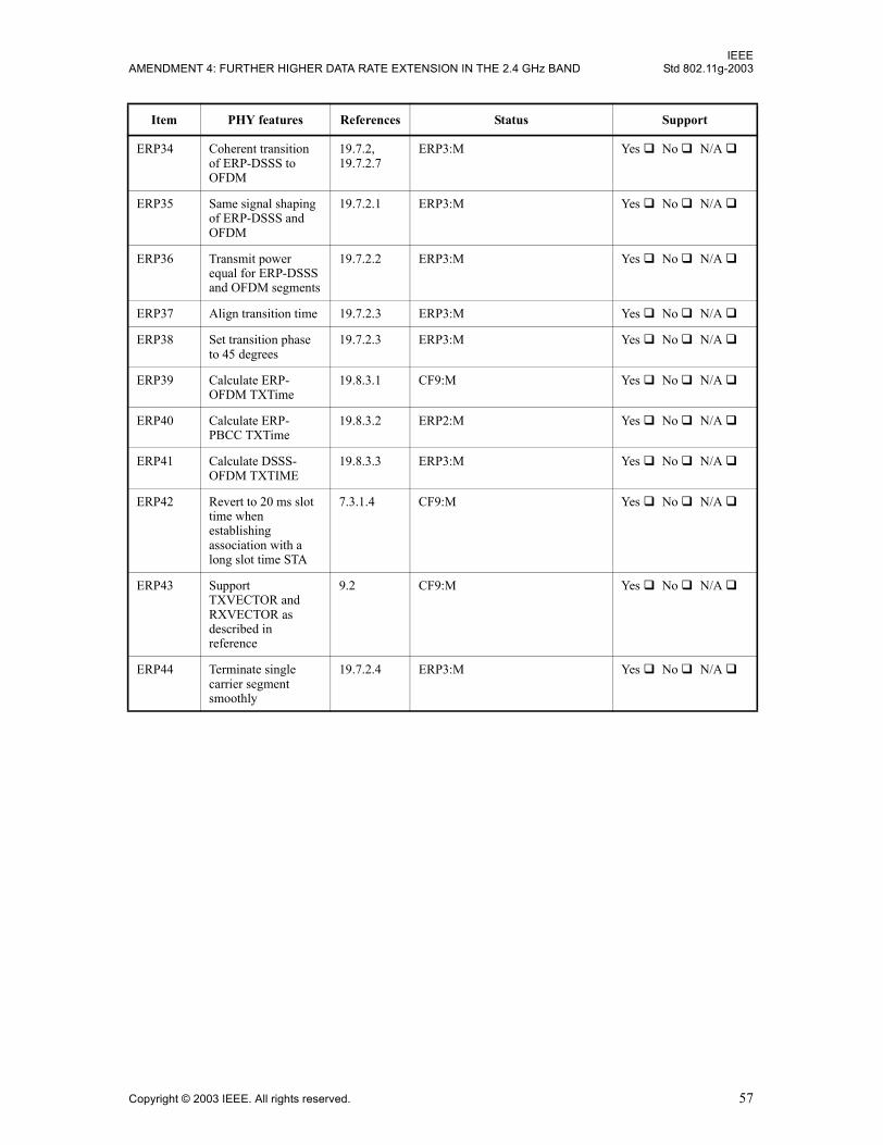
IEEEAMENDMENT 4: FURTHER HIGHER DATA RATE EXTENSION IN THE 2.4 GHz BAND Std 802.11g-2003
ERP34 Coherent transition of ERP-DSSS to OFDM
19.7.2, 19.7.2.7
ERP3:M Yes ! No ! N/A !
ERP35 Same signal shaping of ERP-DSSS and OFDM
19.7.2.1 ERP3:M Yes ! No ! N/A !
ERP36 Transmit power equal for ERP-DSSS and OFDM segments
19.7.2.2 ERP3:M Yes ! No ! N/A !
ERP37 Align transition time 19.7.2.3 ERP3:M Yes ! No ! N/A !
ERP38 Set transition phase to 45 degrees
19.7.2.3 ERP3:M Yes ! No ! N/A !
ERP39 Calculate ERP-OFDM TXTime
19.8.3.1 CF9:M Yes ! No ! N/A !
ERP40 Calculate ERP-PBCC TXTime
19.8.3.2 ERP2:M Yes ! No ! N/A !
ERP41 Calculate DSSS-OFDM TXTIME
19.8.3.3 ERP3:M Yes ! No ! N/A !
ERP42 Revert to 20 ms slot time when establishing association with a long slot time STA
7.3.1.4 CF9:M Yes ! No ! N/A !
ERP43 Support TXVECTOR and RXVECTOR as described in reference
9.2 CF9:M Yes ! No ! N/A !
ERP44 Terminate single carrier segment smoothly
19.7.2.4 ERP3:M Yes ! No ! N/A !
Item PHY features References Status Support
Copyright © 2003 IEEE. All rights reserved. 57
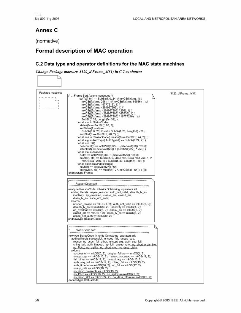
IEEEStd 802.11g-2003 LOCAL AND METROPOLITAN AREA NETWORKS
Annex C
(normative)
Formal description of MAC operation
C.2 Data type and operator definitions for the MAC state machinesChange Package macsorts 3120_d\Frame_4(31) in C.2 as shown:
Package macsorts 3120_d\Frame_4(31)/* ... Frame Sort Axioms continued */
setTs(f, tm) == SubStr(f, 0, 24) // mkOS(fix(tm), 1) //mkOS((fix(tm) / 256), 1) // mkOS((fix(tm) / 65536), 1) //mkOS((fix(tm) / 16777216), 1) //mkOS((fix(tm) / 4294967296), 1) //mkOS(((fix(tm) / 4294967296) / 256), 1) //mkOS(((fix(tm) / 4294967296) / 65536), 1) //mkOS(((fix(tm) / 4294967296) / 16777216), 1) //SubStr(f, 32, Length(f) - 32); );
for all stat in StatusCode(status(f) == SubStr(f, 26, 2);setStatus(f, stat) ==
SubStr(f, 0, 26) // stat // SubStr(f, 28, Length(f) - 28);authStat(f) == SubStr(f, 28, 2); );
for all rea in ReasonCode( reason(f) == SubStr(f, 24, 2); );for all alg in AuthType( AuthType(f) == SubStr(f, 24, 2); );for all u in TU(
beaconInt(f) == octetVal(f(32)) + (octetVal(f(33)) * 256);listenInt(f) == octetVal(f(26)) + (octetVal(f(27)) * 256); );
for all sta in AssocId(AId(f) == octetVal(f(28)) + (octetVal(f(29)) * 256);setAId(f, sta) == SubStr(f, 0, 28) // mkOS(sta mod 256, 1) //
mkOS(sta / 256, 1) // SubStr(f, 30, Length(f) - 30); );for all kid in KeyIndexRange(
keyId(f) == octetVal(f(27)) / 64;setKeyId(f, kid) == Modify!(f, 27, mkOS(kid * 64)); ); )));
endnewtype Frame;
/************************************************************************** ReasonCode sort*************************************************************************/
newtype ReasonCode inherits Octetstring operators all;adding literals unspec_reason, auth_not_valid, deauth_Iv_ss,
inactivity, ap_overload, class2_err, class3_err,disas_Iv_ss, asoc_not_auth;
axiomsunspec_reason == mkOS(1, 2); auth_not_valid == mkOS(2, 2);deauth_Iv_ss == mkOS(3, 2); inactivity == mkOS(4, 2);ap_overload == mkOS(5, 2); class2_err == mkOS(6, 2);class3_err == mkOS(7, 2); disas_Iv_ss == mkOS(8, 2);assoc_not_auth == mkOS(9, 2);
endnewtype ReasonCode;
/************************************************************************** StatusCode sort*************************************************************************/
newtype StatusCode inherits Octetstring operators all;adding literals successful, unspec_fail, unsup_cap,
reasoc_no_asoc, fail_other, unsupt_alg, auth_seq_fail,chlng_fail, auth_timeout, ap_full, unsup_rate, no_short_preamble, no_Pbcc, no_agility, no_short_slot, no_dsss_ofdm;
axiomssuccessful == mkOS(0, 2); unspec_failure == mkOS(1, 2);unsup_cap == mkOS(10, 2); reasoc_no_asoc == mkOS(11, 2);fail_other == mkOS(12, 2); unsupt_alg == mkOS(13, 2);auth_seq_fail == mkOS(14, 2); chlng_fail == mkOS(15, 2);auth_timeout == mkOS(16, 2); ap_full == mkOS(17, 2);unsup_rate == mkOS(18, 2);no_short_preamble == mkOS(19, 2);no_Pbcc == mkOS(20, 2); no_agility == mkOS(21, 2);no_short_slot == mkOS(24, 2); no_dsss_ofdm == mkOS(25, 2);
endnewtype StatusCode;
58 Copyright © 2003 IEEE. All rights reserved.
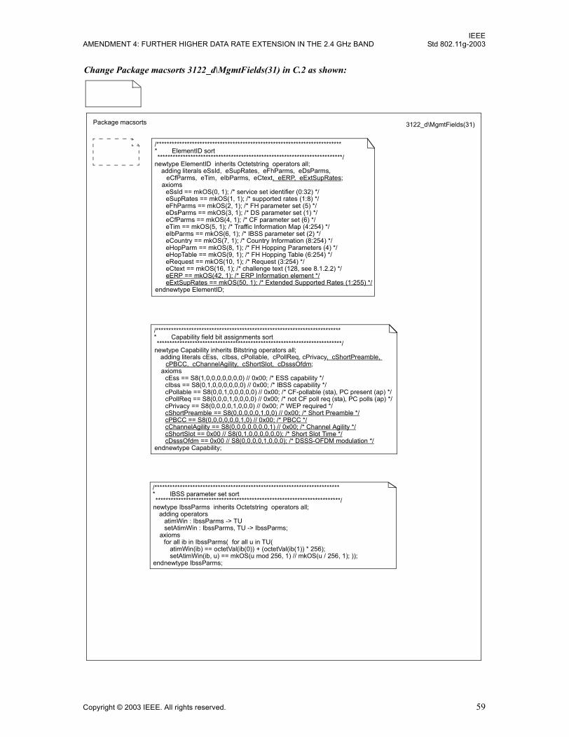
IEEEAMENDMENT 4: FURTHER HIGHER DATA RATE EXTENSION IN THE 2.4 GHz BAND Std 802.11g-2003
Change Package macsorts 3122_d\MgmtFields(31) in C.2 as shown:
/************************************************************************** ElementID sort*************************************************************************/
newtype ElementID inherits Octetstring operators all;adding literals eSsId, eSupRates, eFhParms, eDsParms,
eCfParms, eTim, eIbParms, eCtext, eERP, eExtSupRates;axioms
eSsId == mkOS(0, 1); /* service set identifier (0:32) */eSupRates == mkOS(1, 1); /* supported rates (1:8) */eFhParms == mkOS(2, 1); /* FH parameter set (5) */eDsParms == mkOS(3, 1); /* DS parameter set (1) */eCfParms == mkOS(4, 1); /* CF parameter set (6) */eTim == mkOS(5, 1); /* Traffic Information Map (4:254) */eIbParms == mkOS(6, 1); /* IBSS parameter set (2) */eCountry == mkOS(7, 1); /* Country Information (8:254) */eHopParm == mkOS(8, 1); /* FH Hopping Parameters (4) */eHopTable == mkOS(9, 1); /* FH Hopping Table (6:254) */eRequest == mkOS(10, 1); /* Request (3:254) */eCtext == mkOS(16, 1); /* challenge text (128, see 8.1.2.2) */eERP == mkOS(42, 1); /* ERP Information element */eExtSupRates == mkOS(50, 1); /* Extended Supported Rates (1:255) */
endnewtype ElementID;
/************************************************************************** Capability field bit assignments sort*************************************************************************/
newtype Capability inherits Bitstring operators all;adding literals cEss, cIbss, cPollable, cPollReq, cPrivacy, cShortPreamble,
cPBCC, cChannelAgility, cShortSlot, cDsssOfdm; axioms
cEss == S8(1,0,0,0,0,0,0,0) // 0x00; /* ESS capability */cIbss == S8(0,1,0,0,0,0,0,0) // 0x00; /* IBSS capability */cPollable == S8(0,0,1,0,0,0,0,0) // 0x00; /* CF-pollable (sta), PC present (ap) */cPollReq == S8(0,0,0,1,0,0,0,0) // 0x00; /* not CF poll req (sta), PC polls (ap) */cPrivacy == S8(0,0,0,0,1,0,0,0) // 0x00; /* WEP required */cShortPreamble == S8(0,0,0,0,0,1,0,0) // 0x00; /* Short Preamble */cPBCC == S8(0,0,0,0,0,0,1,0) // 0x00; /* PBCC */cChannelAgility == S8(0,0,0,0,0,0,0,1) // 0x00; /* Channel Agility */cShortSlot == 0x00 // S8(0,1,0,0,0,0,0,0); /* Short Slot Time */cDsssOfdm == 0x00 // S8(0,0,0,0,1,0,0,0); /* DSSS-OFDM modulation */
endnewtype Capability;
/************************************************************************** IBSS parameter set sort*************************************************************************/
newtype IbssParms inherits Octetstring operators all;adding operators
atimWin : IbssParms -> TUsetAtimWin : IbssParms, TU -> IbssParms;
axiomsfor all ib in IbssParms( for all u in TU(
atimWin(ib) == octetVal(ib(0)) + (octetVal(ib(1)) * 256);setAtimWin(ib, u) == mkOS(u mod 256, 1) // mkOS(u / 256, 1); ));
endnewtype IbssParms;
Package macsorts 3122_d\MgmtFields(31)
Copyright © 2003 IEEE. All rights reserved. 59
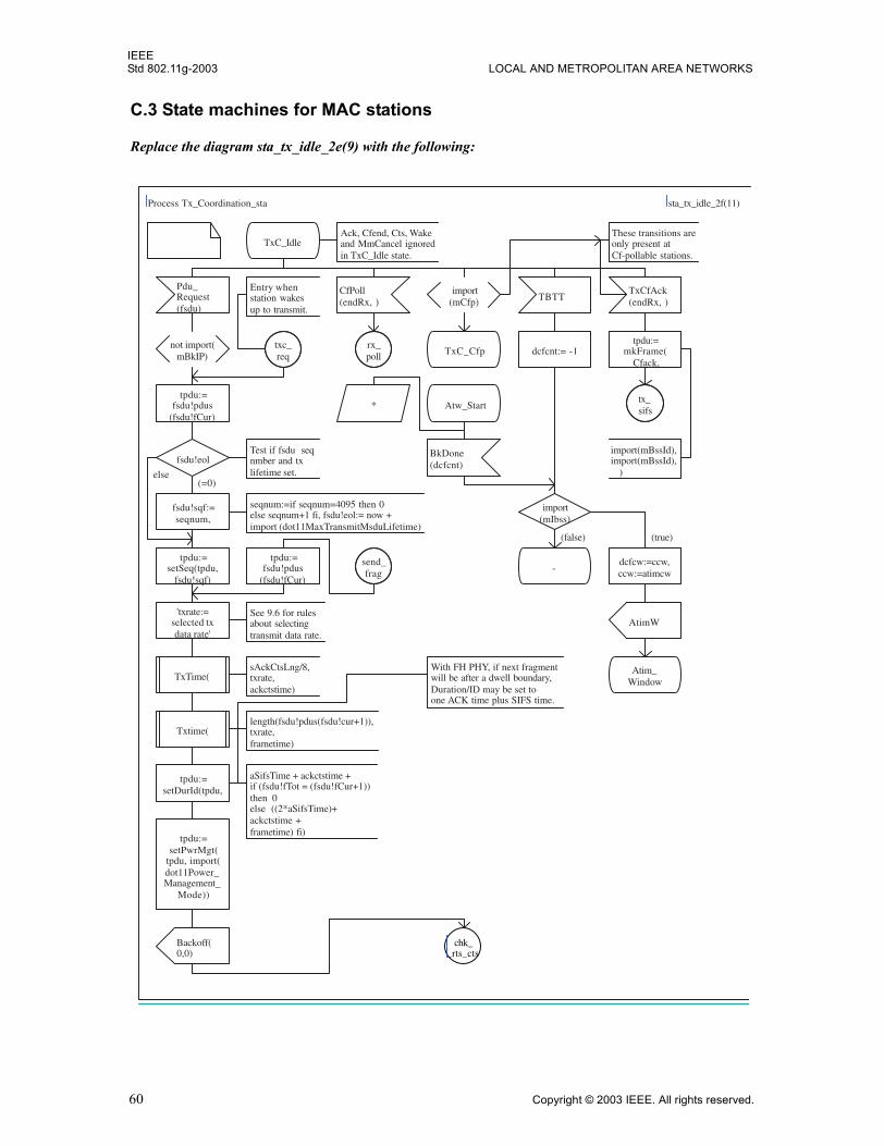
IEEEStd 802.11g-2003 LOCAL AND METROPOLITAN AREA NETWORKS
C.3 State machines for MAC stations
Replace the diagram sta_tx_idle_2e(9) with the following:
Process Tx_Coordination_sta sta_tx_idle_2f(11)
TxC_IdleAck, Cfend, Cts, Wakeand MmCancel ignoredin TxC_Idle state.
Pdu_Request(fsdu)
not import(mBkIP)
tpdu:=fsdu!pdus
(fsdu!fCur)
fsdu!eolTest if fsdu seqnmber and txlifetime set.
fsdu!sqf:=seqnum,
seqnum:=if seqnum=4095 then 0else seqnum+1 fi, fsdu!eol:= now +import (dot11MaxTransmitMsduLifetime)
tpdu:=setSeq(tpdu,
fsdu!sqf)
'txrate:=selected txdata rate'
See 9.6 for rulesabout selectingtransmit data rate.
TxTime(sAckCtsLng/8,txrate,ackctstime)
Txtime(length(fsdu!pdus(fsdu!cur+1)),txrate,frametime)
tpdu:=setDurId(tpdu,
With FH PHY, if next fragmentwill be after a dwell boundary,Duration/ID may be set toone ACK time plus SIFS time.
aSifsTime + ackctstime +if (fsdu!fTot = (fsdu!fCur+1))then 0else ((2*aSifsTime)+ackctstime +frametime) fi)
tpdu:=setPwrMgt(
tpdu, import(dot11Power_Management_
Mode))
Backoff(0,0)
CfPoll(endRx, )
rx_poll
import(mCfp)
These transitions areonly present atCf-pollable stations.
TxC_Cfp
TBTT
dcfcnt:= -1
import(mIbss)
-dcfcw:=ccw,ccw:=atimcw
AtimW
Atim_Window
TxCfAck(endRx, )
tpdu:=mkFrame(
Cfack,
import(mBssId),import(mBssId), )
tx_sifs
txc_req
Entry whenstation wakesup to transmit.
Atw_Start*
BkDone(dcfcnt)
send_frag
tpdu:=fsdu!pdus
(fsdu!fCur)
(=0) else
(false) (true)
chk__rts_cts
60 Copyright © 2003 IEEE. All rights reserved.
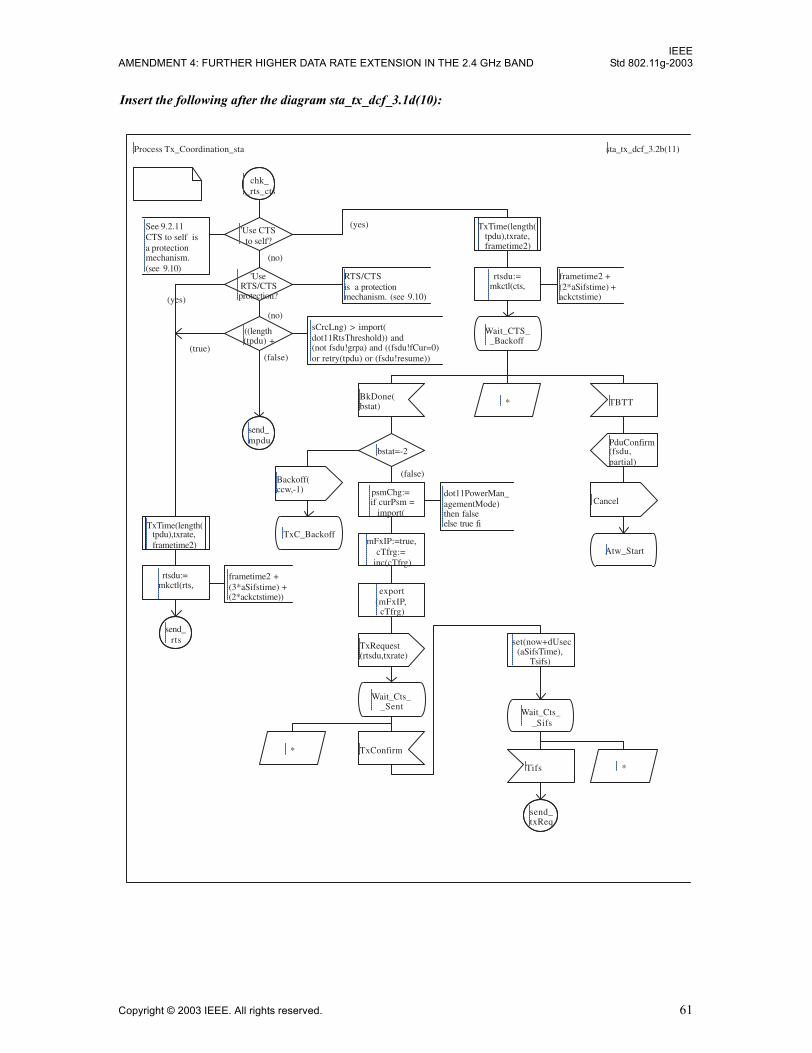
IEEEAMENDMENT 4: FURTHER HIGHER DATA RATE EXTENSION IN THE 2.4 GHz BAND Std 802.11g-2003
Insert the following after the diagram sta_tx_dcf_3.1d(10):
Process Tx_Coordination_sta sta_tx_dcf_3.2b(11)
chk__rts_cts
'Use CTSto self?
TxTime(length(tpdu),txrate,frametime2)
rtsdu:=mkctl(cts,
frametime2 +(2*aSifstime) +ackctstime)
Wait_CTS__Backoff
BkDone(bstat)
bstat=-2
Backoff(ccw,-1)
TxC_Backoff
psmChg:=if curPsm =
import(
dot11PowerMan_agementMode)then falseelse true fi
mFxIP:=true,cTfrg:=
inc(cTfrg)
export(mFxIP,
cTfrg)
TxRequest(rtsdu,txrate)
Wait_Cts__Sent
* TxConfirm
set(now+dUsec(aSifsTime),
Tsifs)
Wait_Cts__Sifs
Tifs
send_txReq
*
* TBTT
PduConfirm(fsdu,partial)
Cancel
Atw_Start
See 9.2.11CTS to self isa protectionmechanism.(see 9.10)
'UseRTS/CTSprotection?
RTS/CTSis a protectionmechanism. (see 9.10)
((length(tpdu) +
sCrcLng) > import(dot11RtsThreshold)) and(not fsdu!grpa) and ((fsdu!fCur=0)or retry(tpdu) or (fsdu!resume))
send_mpdu
TxTime(length(tpdu),txrate,frametime2)
rtsdu:=mkctl(rts,
frametime2 +(3*aSifstime) +(2*ackctstime))
send_rts
(yes)
(false)
(no)
(no)
(false) (true)
(yes)
Copyright © 2003 IEEE. All rights reserved. 61
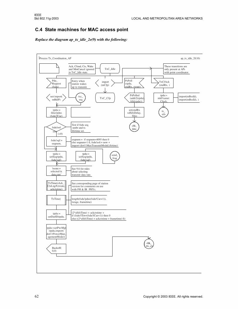
IEEEStd 802.11g-2003 LOCAL AND METROPOLITAN AREA NETWORKS
C.4 State machines for MAC access point
Replace the diagram ap_tx_idle_2e(9) with the following:
Process Tx_Coordination_AP ap_tx_idle_2f(10)
TxC_IdleAck, Cfend, Cts, Wakeand MmCancel ignoredin TxC_Idle state.
Pdu_Request(fsdu)
not import(mBkIP)
tpdu:=fdsu!pdus
(fsdu!fCur)
fsdu!eolTest if fsdu seq nmbr and txlifetime set.
fsdu!sqf:=seqnum,
seqnum:= if seqnum=4095 then 0else seqnum+1 fi, fsdu!eol:= now +import (dot11MaxTransmitMsduLifetime)
tpdu:=setSeq(tpdu,
fsdu!sqf)
'txrate:=selected txdata rate'
See 9.6 for rulesabout selectingtransmit data rate.
TxTime(sAck_CtsLng/8,txrate,
ackctstime)
TxTime( length(fsdu!pdus(fsdu!Cur+1)),txrage, frametime)
tpdu:=setDurID(tpdu,
See corresponding page of stationversion for comments on usewith FH & IR PHYs.
(2*aSifsTime) + ackctstime +if (fsdu!fTot=(fsdu!fCur+1)) then 0else ((2*aSifsTime) + ackctstime + frametime) fi)
tpdu:=setPwrMgt(tpdu,import(
dot11PowerMan_agementMode))
Backoff(0,0)
import(mCfp)
These transitions areonly present at APswith point coordinator.
TxC_Cfp
PsPoll(rpdu,endRx, rxrate)
PsPolled(addr2(rpdu),AId(rpdu))
set(endRx+dSifsDelay,
Tifs)
chk_data
TxCfAck(endRx, )
tpdu:=mkFrame(
Cfack,
import(mBssId),import(mBssId), )
tx_sifs
txc_req
Entry whenstation wakesup to transmit.
send_frag
tpdu:=setSeq(tpdu,
fsdu!sqf)
(=0) else
chk__rts_cts
62 Copyright © 2003 IEEE. All rights reserved.

IEEEAMENDMENT 4: FURTHER HIGHER DATA RATE EXTENSION IN THE 2.4 GHz BAND Std 802.11g-2003
Insert the following after the diagram ap_tx_dcf_3.1e(9):
Process Tx_Coordination_AP ap_tx_dcf.3.2b(10)
chk__rts_cts
See 9.2.11CTS to self isa protectionmechanism.(see 9.10)
'Use CTSto self?
TxTime(length(tpdu),txrate,frametime2)
'UseRTS/CTSprotection?
RTS/CTSis a protectionmechanism. (see 9.10)
rtsdu:=mkctl(cts,
frametime2 +(2*aSifstime) +ackctstime)
((length(tpdu) +
sCrcLng) > import(dot11RtsThreshold)) and(not fsdu!grpa) and ((fsdu!fCur=0)or retry(tpdu) or (fsdu!resume))and (not import(mCfp))
Wait_CTS__Backoff
BkDone(bstat) * TBTT
send_mpdu
bstat=-2PduConfirm(fsdu,partial)
Backoff(ccw,-1) psmChg:=
if curPsm =import(
dot11PowerMan_agementMode)then falseelse true fi
Cancel
TxTime(length(tpdu),txrate,frametime2)
TxC_BackoffmFxIP:=true,
cTfrg:=inc(cTfrg)
Atw_Start
rtsdu:=mkctl(rts,
frametime2 +(3*aSifstime) +(2*ackctstime))
export(mFxIP,
cTfrg)
send_rts
TxRequest(rtsdu,txrate)
set(now+dUsec(aSifsTime ),
Tsifs)
Wait_Cts__Sent
Wait_Cts__Sifs
* TxConfirm
Tifs *
send_txReq
(yes)
(no)
(no)
(yes)
(false) (true)
(false)
Copyright © 2003 IEEE. All rights reserved. 63
IEEEStd 802.11g-2003 LOCAL AND METROPOLITAN AREA NETWORKS
Annex D
(normative)
ASN.1 coding of MAC and PHY MIB
Change the following attribute definitions:
dot11PHYType OBJECT-TYPESYNTAX INTEGER {fhss(1), dsss(2), irbaseband(3), ofdm(4), hrdsss(5), erp(6)}MAX-ACCESS read-onlySTATUS currentDESCRIPTION"This is an 8-bit integer value that identifies the PHYtype supported by the attached PLCP and PMD. Currentlydefined values and their corresponding PHY types are:
FHSS 2.4 GHz = 01, DSSS 2.4 GHz = 02, IR Baseband = 03,
OFDM 5GHz = 04, HRDSSS = 05, ERP = 06 "
::= { dot11PhyOperationEntry 1 }
dot11RTSThreshold OBJECT-TYPESYNTAX INTEGER (0..2347)MAX-ACCESS read-writeSTATUS currentDESCRIPTION"This attribute shall indicate the number of octets in anMPDU, below which an RTS/CTS handshake shall not beperformed, except as RTS/CTS is used as a cross modulationprotection mechanism as defined in 9.10. An RTS/CTShandshake shall be performed at the beginning of any frameexchange sequence where the MPDU is of type Data orManagement, the MPDU has an individual address in theAddress1 field, and the length of the MPDU is greater thanthis threshold. (For additional details, refer to Table 21in 9.7.) Setting this attribute to be larger than themaximum MSDU size shall have the effect of turning off theRTS/CTS handshake for frames of Data or Management typetransmitted by this STA. Setting this attribute to zeroshall have the effect of turning on the RTS/CTS handshakefor all frames of Data or Management type transmitted bythis STA. The default value of this attribute shall be2347."
::= { dot11OperationEntry 2 }
dot11SupportedDataRatesTxIndex OBJECT-TYPESYNTAX Integer32 (1..8255)MAX-ACCESS not-accessibleSTATUS currentDESCRIPTION"Index object that identifies which data rate to access. Range is1..8255."
64 Copyright © 2003 IEEE. All rights reserved.
IEEEAMENDMENT 4: FURTHER HIGHER DATA RATE EXTENSION IN THE 2.4 GHz BAND Std 802.11g-2003
::= { dot11SupportedDataRatesTxEntry 1 }
dot11SupportedDataRatesRxIndex OBJECT-TYPESYNTAX Integer32 (1.. 8255)MAX-ACCESS not-accessibleSTATUS currentDESCRIPTION"Index object that identifies which data rate to access. Range is 1..8255."
::= { dot11SupportedDataRatesRxEntry 1 }
In �Major sections� of Annex D, insert the following text to the end of the �PHY Attributes� section:
--dot11PhyERPTable::= {dot11phy 14}
Insert the following into the IEEE 802.11 MIB in Annex D, between the section entitled �End of dot11Hopping Pattern TABLE� and the section entitled �conformance information�:
-- **********************************************************************
-- * dot11PhyERPEntry TABLE
-- **********************************************************************
dot11PhyERPTable OBJECT-TYPESYNTAX SEQUENCE OF Dot11PhyERPEntryMAX-ACCESS not-accessibleSTATUS currentDESCRIPTION"Entry of attributes for dot11PhyERPEntry. Implementedas a table indexed on ifIndex to allow for multipleinstances on an Agent."
::= { dot11phy 14 }
dot11PhyERPEntry OBJECT-TYPESYNTAX Dot11PhyERPEntryMAX-ACCESS not-accessibleSTATUS currentDESCRIPTION"An entry in the dot11PhyERPEntry Table. ifIndex - Each 802.11 interface is represented by anifEntry. Interface tables in this MIB module are indexedby ifIndex."
INDEX {ifIndex}::= { dot11PhyERPTable 1 }
Dot11PhyERPEntry ::= SEQUENCE {dot11ERPPBCCOptionImplemented TruthValue,dot11ERPBCCOptionEnabled TruthValue,dot11DSSSOFDMOptionImplemented TruthValue,dot11DSSSOFDMOptionEnabled TruthValue,dot11ShortSlotTimeOptionImplemented TruthValue,
Copyright © 2003 IEEE. All rights reserved. 65
IEEEStd 802.11g-2003 LOCAL AND METROPOLITAN AREA NETWORKS
dot11ShortSlotTimeOptionEnabled TruthValue }
dot11ERPPBCCOptionImplemented OBJECT-TYPESYNTAX TruthValueMAX-ACCESS read-onlySTATUS currentDESCRIPTION"This attribute, when true, shall indicate that the ERP-PBCC modulation option as defined in 19.6 is imple-mented. The default value of this attribute is false."
::= {dot11PhyERPEntry 1 }
dot11ERPBCCOptionEnabled OBJECT-TYPESYNTAX TruthValueMAX-ACCESS read-writeSTATUS currentDESCRIPTION"This attribute, when true, shall indicate that the ERP-PBCCoption as defined in 19.6 is enabled. The defaultvalue of this attribute is false."
::= {dot11PhyERPEntry 2 }
dot11DSSSOFDMOptionImplemented OBJECT-TYPESYNTAX TruthValueMAX-ACCESS read-onlySTATUS currentDESCRIPTION"This attribute, when true, shall indicate that theDSSS-OFDM option as defined in 19.7 is implemented. Thedefault value of this attribute is false."
::= {dot11PhyERPEntry 3 }
dot11DSSSOFDMOptionEnabled OBJECT-TYPESYNTAX TruthValueMAX-ACCESS read-writeSTATUS currentDESCRIPTION"This attribute, when true, shall indicate that theDSSS-OFDM option as defined in 19.7 is enabled. Thedefault value of this attribute is false."
::= {dot11PhyERPEntry 4 }
dot11ShortSlotTimeOptionImplemented OBJECT-TYPESYNTAX TruthValueMAX-ACCESS read-writeSTATUS currentDESCRIPTION"This attribute, when true, shall indicate that theShort Slot Time option as defined in 7.3.1.4 is imple-mented. The default value of this attribute is false."
::= {dot11PhyERPEntry 5}
66 Copyright © 2003 IEEE. All rights reserved.

IEEEAMENDMENT 4: FURTHER HIGHER DATA RATE EXTENSION IN THE 2.4 GHz BAND Std 802.11g-2003
dot11ShortSlotTimeOptionEnabled OBJECT-TYPESYNTAX TruthValueMAX-ACCESS read-writeSTATUS currentDESCRIPTION"This attribute, when true, shall indicate that theShort Slot Time option as defined in 7.3.1.4 is enabled.The default value of this attribute is false."
::= {dot11PhyERPEntry 6 }
-- **********************************************************************
-- * End of dot11PhyERPEntry TABLE
-- **********************************************************************
Insert a new compliance group to the compliance statements just before the section �OPTIONAL-GROUPS�:
GROUP dot11PhyERPComplianceGroupDESCRIPTION"Implementation of this group is required when objectdot11PHYType has the value of ERP. This group is mutu-ally exclusive with the groups dot11PhyIRComplianceGroupand dot11PhyFHSSComplianceGroup."
Insert the following text into the IEEE 802.11 MIB in Annex D, after the definition of thedot11PhyFHSSComplianceGroup2 Object Group:
dot11PhyERPComplianceGroup OBJECT-GROUPOBJECTS {dot11CurrentChannel, dot11ShortPreambleOptionImplemented,dot11ChannelAgilityPresent,dot11ChannelAgilityEnabled,dot11DSSSOFDMOptionImplemented,dot11DSSSOFDMOptionEnabled,dot11PBCCOptionImplemented,dot11ERPPBCCOptionImplemented,dot11ShortSlotTimeOptionImplemented,dot11ShortSlotTimeOptionEnabled }
STATUS currentDESCRIPTION"Attributes that configure the ERP."
::= { dot11Groups 24}
Copyright © 2003 IEEE. All rights reserved. 67