IEEE PROCEEDINGS, VOL. XXX, NO. YYY, DATE 1 Distributed ...sseshia/pubdir/DistributedRealTim… ·...
13
IEEE PROCEEDINGS, VOL. XXX, NO. YYY, DATE 1 Distributed Real-Time Software for Cyber-Physical Systems John C. Eidson, Life Fellow, IEEE, Edward A. Lee, Fellow, IEEE, Slobodan Matic, Member, IEEE, Sanjit A. Seshia, Member, IEEE, and Jia Zou, Student Member, IEEE Abstract—Real-time embedded software today is commonly built using programming abstractions with little or no temporal semantics. This paper addresses this problem by presenting a programming model called PTIDES that serves as a coordination language for model-based design of distributed real-time embed- ded systems. Specifically, the paper describes the principles of PTIDES, which leverages network time synchronization to pro- vide a determinate distributed real-time semantics. We show how PTIDES can function as a coordination language, orchestrating components that may be designed and specified using different formalisms. We show the use of this environment in the design of interesting and practical cyber-physical systems, such as a power plant control system. I. I NTRODUCTION In cyber-physical systems (CPS) the passage of time be- comes a central feature of system behavior — in fact, it is one of the important constraints distinguishing these systems from distributed computing in general. Time is central to predicting, measuring, and controlling properties of the physical world: given a physical model, the initial state, the inputs, and the amount of time elapsed, one can compute the current state of the plant. This principle provides the foundations of control theory. However, for current mainstream programming paradigms, given the source code, the program’s initial state, and the amount of time elapsed, we cannot reliably predict future program states. When that program is integrated into a system with physical dynamics, this makes principled design of the entire system difficult. Moreover, the disparity between the dynamics of the physical plant and the program potentially leads to errors, some of which can be catastrophic. The challenge of integrating computing and physical pro- cesses has been recognized for some time, motivating the emergence of hybrid systems theories. Progress in that area, The authors are with the EECS Department of UC Berke- ley. Contact them at {eidson, eal, matic, sseshia, jiazou}@eecs.berkeley.edu. This work was supported in part by the Center for Hybrid and Embedded Software Systems (CHESS) at UC Berkeley, which receives support from the National Science Foundation (NSF awards #0720882 (CSR-EHS: PRET), #0931843 (ActionWebs), and #1035672 (CSR-CPS Ptides)), the U. S. Army Research Office (ARO #W911NF-07-2-0019), the U. S. Air Force Office of Scientific Research (MURI #FA9550-06-0312), the Air Force Research Lab (AFRL), the Multiscale Systems Center (MuSyC), one of six research centers funded under the Focus Center Research Program, a Semiconductor Research Corporation program, and the following companies: Bosch, National Instruments, Thales, and Toyota. The fourth author was also supported in part by NSF grant #0644436 and an Alfred P. Sloan Research Fellowship. Manuscript received February 28, 2011. however, remains limited to relatively simple systems com- bining ordinary differential equations with automata. These models inherit from control theory a uniform notion of time, an oracle called t available simultaneously in all parts of the system. Even though traditional computer science concepts in distributed systems emphasize asynchrony, when these concepts are adapted to control problems, researchers often make the assumption of the oracle t. For example, in [21], consensus problems from computer science are translated into control systems formulations, but with the introduction of this global binding notion of time. In networked software implementations, such a uniform notion of time cannot be precisely realized. Time triggered networks [12] can be used to approximate a uniform model of time, but the analysis of the dynamics has to include the imperfections. Although design of real-time software is not a new problem, there exist trends with a potential to change the landscape. Model-based design [11], for example, has caught on in industrial practice, through the use of tools such as Simulink, TargetLink, and LabVIEW. Domain-specific modeling lan- guages are increasingly being used because they tend to have formal semantics that experts can use to describe their domain constraints. For CPS, models with temporal semantics are particularly natural to system designers. An example of such a language is Timing-Augmented Description Language [10], a domain-specific language recently developed within the automotive initiative AUTOSAR. A formal semantics enables safety verification of individ- ual components and helps with integration of components into systems. Safety and dependability are emphasized in the synchronous-reactive languages, particularly Esterel and SCADE [1], used primarily in safety critical applications. An example that addresses integration and mutual consistency issues of different modeling languages is the UML extension called MARTE (Modeling and Analysis of Real-Time and Embedded Systems). Some frameworks, like BIP [2], are component frameworks based on formal verification methods, and they address both issues. BIP focuses on compositional verification of properties such as deadlock freedom and relies on priorities to model scheduling policies. As far as we know, it has not been used to address modeling and design problems for components with explicit timing requirements. The model- based design approach we propose in this paper borrows sound fixed-point semantics from the synchronous languages, but is more flexible and concurrent. To control timing in embedded software, programmers typically use platform-specific system timers. However, de-
Transcript of IEEE PROCEEDINGS, VOL. XXX, NO. YYY, DATE 1 Distributed ...sseshia/pubdir/DistributedRealTim… ·...

IEEE PROCEEDINGS, VOL. XXX, NO. YYY, DATE 1
Distributed Real-Time Softwarefor Cyber-Physical Systems
John C. Eidson, Life Fellow, IEEE, Edward A. Lee, Fellow, IEEE, Slobodan Matic, Member, IEEE,Sanjit A. Seshia, Member, IEEE, and Jia Zou, Student Member, IEEE
Abstract—Real-time embedded software today is commonlybuilt using programming abstractions with little or no temporalsemantics. This paper addresses this problem by presenting aprogramming model called PTIDES that serves as a coordinationlanguage for model-based design of distributed real-time embed-ded systems. Specifically, the paper describes the principles ofPTIDES, which leverages network time synchronization to pro-vide a determinate distributed real-time semantics. We show howPTIDES can function as a coordination language, orchestratingcomponents that may be designed and specified using differentformalisms. We show the use of this environment in the design ofinteresting and practical cyber-physical systems, such as a powerplant control system.
I. INTRODUCTION
In cyber-physical systems (CPS) the passage of time be-comes a central feature of system behavior — in fact, it is oneof the important constraints distinguishing these systems fromdistributed computing in general. Time is central to predicting,measuring, and controlling properties of the physical world:given a physical model, the initial state, the inputs, andthe amount of time elapsed, one can compute the currentstate of the plant. This principle provides the foundations ofcontrol theory. However, for current mainstream programmingparadigms, given the source code, the program’s initial state,and the amount of time elapsed, we cannot reliably predictfuture program states. When that program is integrated into asystem with physical dynamics, this makes principled designof the entire system difficult. Moreover, the disparity betweenthe dynamics of the physical plant and the program potentiallyleads to errors, some of which can be catastrophic.
The challenge of integrating computing and physical pro-cesses has been recognized for some time, motivating theemergence of hybrid systems theories. Progress in that area,
The authors are with the EECS Department of UC Berke-ley. Contact them at {eidson, eal, matic, sseshia,jiazou}@eecs.berkeley.edu.
This work was supported in part by the Center for Hybrid and EmbeddedSoftware Systems (CHESS) at UC Berkeley, which receives support fromthe National Science Foundation (NSF awards #0720882 (CSR-EHS: PRET),#0931843 (ActionWebs), and #1035672 (CSR-CPS Ptides)), the U. S.Army Research Office (ARO #W911NF-07-2-0019), the U. S. Air ForceOffice of Scientific Research (MURI #FA9550-06-0312), the Air ForceResearch Lab (AFRL), the Multiscale Systems Center (MuSyC), one ofsix research centers funded under the Focus Center Research Program, aSemiconductor Research Corporation program, and the following companies:Bosch, National Instruments, Thales, and Toyota. The fourth author was alsosupported in part by NSF grant #0644436 and an Alfred P. Sloan ResearchFellowship.
Manuscript received February 28, 2011.
however, remains limited to relatively simple systems com-bining ordinary differential equations with automata. Thesemodels inherit from control theory a uniform notion of time,an oracle called t available simultaneously in all parts of thesystem. Even though traditional computer science conceptsin distributed systems emphasize asynchrony, when theseconcepts are adapted to control problems, researchers oftenmake the assumption of the oracle t. For example, in [21],consensus problems from computer science are translated intocontrol systems formulations, but with the introduction ofthis global binding notion of time. In networked softwareimplementations, such a uniform notion of time cannot beprecisely realized. Time triggered networks [12] can be usedto approximate a uniform model of time, but the analysis ofthe dynamics has to include the imperfections.
Although design of real-time software is not a new problem,there exist trends with a potential to change the landscape.Model-based design [11], for example, has caught on inindustrial practice, through the use of tools such as Simulink,TargetLink, and LabVIEW. Domain-specific modeling lan-guages are increasingly being used because they tend tohave formal semantics that experts can use to describe theirdomain constraints. For CPS, models with temporal semanticsare particularly natural to system designers. An example ofsuch a language is Timing-Augmented Description Language[10], a domain-specific language recently developed within theautomotive initiative AUTOSAR.
A formal semantics enables safety verification of individ-ual components and helps with integration of componentsinto systems. Safety and dependability are emphasized inthe synchronous-reactive languages, particularly Esterel andSCADE [1], used primarily in safety critical applications. Anexample that addresses integration and mutual consistencyissues of different modeling languages is the UML extensioncalled MARTE (Modeling and Analysis of Real-Time andEmbedded Systems). Some frameworks, like BIP [2], arecomponent frameworks based on formal verification methods,and they address both issues. BIP focuses on compositionalverification of properties such as deadlock freedom and relieson priorities to model scheduling policies. As far as we know,it has not been used to address modeling and design problemsfor components with explicit timing requirements. The model-based design approach we propose in this paper borrows soundfixed-point semantics from the synchronous languages, but ismore flexible and concurrent.
To control timing in embedded software, programmerstypically use platform-specific system timers. However, de-
IEEE PROCEEDINGS, VOL. XXX, NO. YYY, DATE 2
sign of a system should be as independent of implemen-tation details as possible, to allow for portability and de-sign space exploration. To this end, we have previouslyproposed a programming model called PTIDES (program-ming temporally-integrated distributed embedded systems, pro-nounced “tides”) [29]. PTIDES structures real-time softwareas an interconnection of components communicating usingtimestamped events. Ptides leverages network time synchro-nization to provide a coherent global temporal semantics indistributed systems. With PTIDES, application programmersspecify the interaction between the control program and thephysical dynamics in the system model, without the knowledgeof low-level details such as timers.
Prior work on PTIDES includes a study of the semanticproperties of an execution model that permits out of order pro-cessing of events without sacrificing determinacy and withoutrequiring backtracking [32]. The same work introduces feasi-bility analysis for PTIDES programs, a problem that is onlypartially solved. PTIDES has been used to coordinate real-time components written in Java [31] and C [33], where the“glue code” is automatically generated from PTIDES models.A simulator has been developed that supports joint modelingof PTIDES controllers, physical plants, and communicationnetworks [5], [33].
The goal of this paper is to review the principles of PTIDESand to demonstrate its usefulness for time-critical CPS ap-plications. We first explain how PTIDES models providedeterministic processing of events. Building on [32], in thispaper (Sec. II-C), we consider the networked case, derivingbounds for deadlines for event network transmissions. Then weillustrate how to specify timed reactions to events in PTIDESmodels. This results in identical traces from model simulationand execution of automatically generated code.
In order to account for different modes of operation, modalmodels have been widely used in embedded system design [8].By “modal models,” we mean the use of state machinesthat define modes of operation and govern the switchingbetween modes [16]. In this paper, we introduce the useof modal PTIDES models. This combination enables precisespecification of timed mode transitions.
This paper is organized as follows. First, section II discussesthe PTIDES design environment, which enables a programmerto first model and simulate the design and then implementit through a target-specific code generator. This environmentextends Ptolemy II [7] to realize a coordination language forthe design of distributed real-time embedded systems and toprovide a co-simulator for embedded software, physical plants,and networks. Section III then explains temporal semanticsof PTIDES, and shows how the use of modal models in thecontext of PTIDES provides a firm basis for the design ofan important class of CPS. This is followed by a detailedapplication example in section IV. We conclude in section V.
II. DESIGN ENVIRONMENT
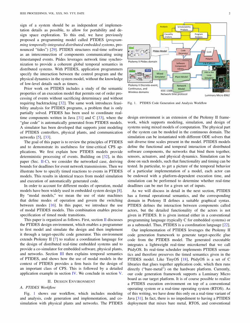
A. PTIDES WorkflowFig. 1 shows our workflow, which includes modeling
and analysis, code generation and implementation, and co-simulation with physical plants and networks. The PTIDES
!"#$%&'()*#+(,-&).#
/(*0(1.12#
345)&)6#
$78.9#:(8.%# /(8.#
;.1.)&2()#
$786<+#
/(8.#
$%&12#:(8.%#
1.
=.2-()>#
:(8.%#
!"#41#2?.#
3((0#
+4*@%&2()#
/&@9&%426#
A1&%6949#
/
A
$)(B)&*#
A1&%6949#
/
+C?.8@%&54%426#
A1&%6949#
A1&%6949#
:4D.8#
+4*@%&2()#
!"#$%&'()*#&).#
1.12#
)66
((8.#
..)&2()#()#
!" $% '
$
:(8.%#
..)&
-()>#
8.%
!"#41#2?.#
3((0#
+4*@%&2()
$)(B)&*#
A1&%6949#
8
8@%&54%426#
1&%6949#
+4*@%&
$%&'
" 41 2
$786<+
/(8.#
$2(%.*6#EE#$78.9#8(*&41#
$2(%.*6#EE#F49C).2.G.H.12I#
/(171@(@9I#&18#
"4).%.99#8(*&419#
3@*41&)6#:4C)(#JKLM#
ENNN#OPJJ#
=.2-()>#7*.#0)(2(C(%#
Fig. 1. PTIDES Code Generation and Analysis Workflow
design environment is an extension of the Ptolemy II frame-work, which supports modeling, simulation, and design ofsystems using mixed models of computation. The physical partof the system can be modeled in the continuous domain. Thesimulation can be instantiated with different ODE solvers thatsuit diverse time scales present in the model. PTIDES modelsdefine the functional and temporal interaction of distributedsoftware components, the networks that bind them together,sensors, actuators, and physical dynamics. Simulation can bedone on such models, such that functionality and timing can betested. In particular, to get a picture of the temporal behaviorof a particular implementation of a model, each actor canbe endowed with a platform-dependent execution time, andsimulation can be performed to determine whether real-timedeadlines can be met for a given set of inputs.
As we will discuss in detail in the next section, PTIDEShas a formal operational semantics, and the correspondingdomain in Ptolemy II defines a suitable graphical syntax.PTIDES defines the interaction between components calledactors, but the detailed functionality of the actors is notgiven in PTIDES. It is given instead either in a conventionalprogramming language (typically C for embedded systems) oras a submodel. Thus, PTIDES is a coordination language [22].
Our implementation of PTIDES leverages the Ptolemy IIcode generation framework to generate target-specific gluecode from the PTIDES model. The generated executableintegrates a lightweight real-time microkernel that we callPtidyOS. Its real-time scheduler implements PTIDES seman-tics and therefore preserves the timed semantics given in thePTIDES model. Like TinyOS [18], PtidyOS is a set of Clibraries that glues together application code, which then runsdirectly (“bare-metal”) on the hardware platform. Currently,our code generation framework supports a Luminary Microboard as our target platform. It is of course possible to realizea PTIDES execution environment on top of a conventionaloperating system or a real-time operating system (RTOS). Asof this writing, we have done this only on a real-time variant ofJava [31]. In fact, there is no impediment to having a PTIDESdeployment that mixes bare metal, RTOS, and conventional

IEEE PROCEEDINGS, VOL. XXX, NO. YYY, DATE 3
OS platforms, although overall system tolerances (like clocksynchronization precision) may end up being determined bythe worst case platforms.
The goal of PTIDES timed semantics is to capture systemtiming requirements. It is then necessary to check that thegenerated code running on the target platform will be ableto meet these requirements. There are several approaches toanswer this schedulability question. One approach is detailedin the workflow diagram, which shows schedulability analysis,the goal of which is to statically determine whether alldeadlines can be met. This analysis requires platform-specificinformation such as worst-case execution time (WCET) foreach actor and an event model for each sensor and networkinput (i.e., the rate and pattern of event streams arrivingat sensors and network input ports). The values of theseparameters are not always known definitively, so schedulabilityanalysis may be approximate. In fact, it is easy to show thatthe schedulability analysis problem is undecidable in general,so approximations will be necessary.
In this paper, we describe a co-simulation approach toschedulability analysis. The programmer annotates each actorwith a WCET (which may be approximated using programanalysis tools [23], [24]) and specifies the input event models.Simulation then lends insight into the real-time behavior of thesystem, building confidence in the design. Deadline missesare recorded during simulation. GAMETIME, a systematicmeasurement-based approach to execution time analysis [24],[25], [26], can be used not only for predicting the WCET, butalso to generate test cases that are reasonably comprehensivefor use in simulation.
Though we have carried out modeling, simulation, andimplementation of a number of small examples using thePTIDES simulator and PtidyOS, in this paper we only focuson the modeling and simulation aspects in order to illustratehow one can program distributed cyber-physical systems usingexplicit timing constraints.
B. Model Time and Physical TimePTIDES is based on discrete-event (DE) systems [3] [28],
which provide a model of time and concurrency. We specifyDE systems using the actor-oriented approach [14]. In thiscase, the actors are concurrent components that exchange time-stamped events via input and output ports. The time in timestamps is a part of the model, playing a formal role in thecomputation. We refer to this time as model time. It may ormay not bear any relationship to time in the physical world,which in this paper we will call physical time. In basic DEsemantics, each actor processes input events in time-stamporder. There are no constraints on the physical time at whichevents are processed. We assume a variant of DE that has beenshown to integrate well with models of continuous dynamics[17]. The purpose of this paper is not to study its rigorous anddeterminate semantics. For that an interested reader is referredto [19] and [13].
PTIDES extends DE by establishing a relationship be-tween model time and physical time at sensors, actuators,and network interfaces. Whereas DE models have tradition-ally been used to construct simulations, PTIDES provides a
programmer’s model for the specification of both functionaland temporal properties of deployable cyber-physical systems.There are three key constraints that define the relationshipbetween model time and physical time: 1) sensors produceevents with timestamp τ at physical time t ≥ τ ; 2) actuatorsreceive events with timestamp τ at physical time t ≤ τ , and 3)network interfaces act as actuators when sending messages andas sensors when receiving them. We explain these constraintsin detail below.
The basic PTIDES model is explained by referring to Figure2, which shows three computational platforms (typically em-bedded computers) connected by a network and having localsensors and actuators. On Platform 3, a component labeledLocal Event Source produces a sequence of events that drivean actuator through two other components. The componentlabeled Computation4 processes each event and produces anoutput event with the same time stamp as the input eventthat triggers the computation. Those events are merged intime stamp order by a component Merge and delivered to acomponent labeled Actuator1.
In PTIDES, an actuator component interprets its inputevents as commands to perform some physical action at aphysical time equal to the time stamp of the event. Thephysical time of this event is measured based on clockscommensurate with UTC or a local system-wide real-timeclock. This interpretation imposes our first real-time constrainton all the software components upstream of the actuator. Eachevent must be delivered to the actuator at a physical timeearlier than the event’s time stamp to meet deadlines. EitherPtidyOS or the design of the actuator itself ensures that theactuation affects the physical world at a time equal to the eventtime stamp. Therefore the deployed system exhibits the exacttemporal behavior specified in the design to within the limitsof the accuracy of clock synchronization between platformsand the temporal resolution of the actuators and clocks.
In Figure 2, Platform 3 contains an actuator that is affectedboth by some local control and by messages received overthe network. The local control commands are generated bythe actor Local Event Source, and modified by the componentComputation4. The Merge component can inject commands tothe actuator that originate from either the local event source orfrom the network. The commands are merged in order of theirtime stamps. Notice that the top input to the Merge componentcomes from components that get inputs from sensors on theremote platforms. The sensor components produce on theiroutput ports time-stamped events. Here, the PTIDES modelimposes a second relationship between model time stamps andphysical time. Specifically, when a sensor component producesa time-stamped output event, that time stamp must be less thanor equal to physical time, however physical time is measured.The sensor can only tell the system about the past, not aboutthe future.
The third and final relationship refers to network interfaces.In this work we assume that the act of sending an event via anetwork is similar to delivering an event to an actuator; i.e., theevent must be delivered to the network interface by a deadlineequal to the time stamp of the event. Consider Platform 1 inFigure 2 as an example. When an event of time stamp τ is to

IEEE PROCEEDINGS, VOL. XXX, NO. YYY, DATE 4
Fig. 2. Prototypical CPS
be sent into the network fabric, the transmission of this eventneeds to happen no later than physical time τ . In general,we could set the deadline to something other than the timestamp, but for our purposes here, it is sufficient that therebe a deadline, and that the deadline be a known function ofthe time stamp. We discuss options for this function in thefollowing subsection.
C. Event Processing in PTIDES
Under benign conditions [13], DE models are determinate inthat given the time-stamped inputs to the model, all events arefully defined. Thus, any correct execution of the model mustdeliver the same time-stamped events to actuators, given thesame time-stamped events from the sensors (this assumes thateach software component is itself determinate). An executionof a PTIDES model is required to follow DE semantics,and hence deliver this determinacy. It is this property thatmakes executions of PTIDES models repeatable. A test ofany “correct” execution of a PTIDES model will match thebehavior of any other correct execution.
The key question is how to deliver a “correct” execution.For example, consider the Merge component in Figure 2. Thiscomponent must merge events in time-stamp order for deliveryto the actuator. Given an event from the local Computation4component, when can it safely pass that event to the actuator?Here lies a key feature of PTIDES. The decision to pass theevent to the actuator is made locally at run time by comparingthe time stamp of the event against a local clock that is trackingphysical time. This strategy results in decentralized control,removing the risks introduced by a single point of failure, andmaking systems much more modular and composable.
There are two key assumptions made in PTIDES. First,distributed platforms have real-time clocks synchronized withbounded error. The PTIDES model of computation workswith any bound on the error, but the smaller the bound, thetighter the real-time constraints can be. Time synchronizationtechniques such as IEEE 1588 [9] can deliver real-time clockprecision on the nanosecond order.
Second, PTIDES requires that there be a bound on thecommunication delay between any two hardware components.Specifically, sensors and actuators must deliver time-stampedevents to the run-time system within a bounded delay, and anetwork must transport a time-stamped event with a boundeddelay. Bounding network delay is potentially more problematicwhen using generic networking technologies such as Ethernet,but bounded network delay is already required today in theapplications of interest here. This has in fact historicallyforced deployments of these applications to use specializednetworking techniques (such as time-triggered architectures[12], FlexRay [20], and CAN buses [27]). One of the goals ofour research is to use PTIDES on less constraining networkingarchitectures, e.g. to allow more flexibility in processingaperiodic events. In the time-triggered architectures, all actionsare initiated by the computer system at known time instants. Inour approach, events coming from the environment are allowedand are treated deterministically. Here it is sufficient to observethat these boundedness assumptions are achievable in practice.Since PTIDES allows detection of run-time timing errors, it ispossible to model responses to failures of these assumptions.
Once these two assumptions (bounded time synchronizationerror and communication delays) are accepted, together withdeadlines for network interfaces and actuators, local decisionscan be made to deliver events in Figure 2 without compromis-

IEEE PROCEEDINGS, VOL. XXX, NO. YYY, DATE 5
ing DE semantics. Specifically, in Figure 2, notice that the topinput to the Merge comes from Sensor1 and Sensor2 througha chain of software components and a network link. Staticanalysis of these chains reveals the operations performed ontime stamps. In particular, in this figure, assume that the onlycomponents that manipulate time stamps are the componentslabeled model time delay di. These components accept an inputevent and produce an output event with the same data but witha time stamp incremented by di.
Assume we have an event e with time stamp τ at the bottominput of Merge, and that there is no other event on Platform3 with an earlier time stamp. This event can be passed tothe output only when we are sure that no event will laterappear at the top input of Merge with a time stamp less thanor equal to τ . This will preserve DE semantics. When can webe sure that e is safe to process in this way? We assume thatevents destined to the top input of Merge must be producedby a reaction in Computation3 to events that arrive over thenetwork. Moreover, the outputs of Computation3 are furtherprocessed to increment their time stamps by d2. Thus, we aresure e is safe to process when no events from the networkwill arrive at Platform 3 with time stamps less than or equalto τ − d2. When can we be sure of this? Let us assumea network delay bound of n and a clock synchronizationerror bound of s between platforms. By the network interfaceassumption discussed above, we know that all events sent byPlatform 1 or Platform 2 with time stamps less than τ − d2
will be sent over the network by the physical time τ − d2.Consequently, all events with time stamp less than or equalto τ − d2 will be received on Platform3 by the physical timeτ − d2 + n + s, where the s term accounts for the possibledisagreement in the measurement of physical time. Thus whenphysical time on Platform 3 exceeds τ − d2 + n + s, event ewill be safe to process. In other words, to ensure that theprocessing of an event obeys DE semantics, at run time,the only test that is needed is to compare time stamps tophysical time with an offset (in the previous example, theoffset is −d2 + n + s). This operation, thus, takes constanttime per event. Notice, if we assume the model is static(components are not added during runtime and connections arenot changed); minimum bounds on model time delays (di’s)for components are known statically; and the upper boundsfor sensor processing times, network delays, and networksynchronization errors are known, then the offsets can becalculated statically using a graph traversal algorithm whichtakes linear time in the number of model actors.
The expression presented in the previous paragraph wasderived under the assumption that the deadline at a networkinterface for the transmission of an event with time stamp τis equal to the time stamp, D(τ) = τ . However, given thePTIDES program with known model time delay values for allactors, there is actually a range of possible network interfacedeadlines, where the range is defined by constraints imposedat sensor-actuator boundaries. The lower bound of this rangeis determined by the constraint that sensor events are producedat physical time greater than the time stamp. In particular, inFigure 2, the network interface deadline of an event with timestamp τ at the output of the Computation1 actor cannot be
lower than Dl(τ) = τ−d4, because this is the earliest physicaltime a sensor event with time stamp τ − d4 can be detectedat Sensor1. This bound assumes zero execution time of theComputation1 actor. The upper bound of the network interfacedeadline range is determined by the constraint that actuatorevents are received at physical time smaller than the timestamp. In Figure 2 this upper bound for the network interface atthe output of the Computation1 actor is determined by Actua-tor1 on the receiving platform Platform3 and the network delaybound n and clock synchronization error bound of s. Thisbound is Du(τ) = τ+d2−n−s because an event at the outputof the Computation1 actor with time stamp τ1 = τ −d2 couldbecome available at the upper input of the Merge actor no laterthan at physical time Du(τ1)+n+s = Du(τ −d2)+n+s =((τ − d2) + d2 − n − s) + n + s = τ , which is the upperbound on physical time an event with time stamp τ should bereceived by Actuator1. This bound assumes zero executiontime of Computation3 actor. So, the theoretical bounds onnetwork interface deadline in this case are Dl(τ) = τ − d4
and Du(τ) = τ + d2 − n − s. Our assumption that thedeadline equals the time stamp τ makes the analysis in nextsubsections particularly simple, so for the purposes of thispaper we proceed with that. A possible consequence of thisassumption on performance will be addressed in our futurework.
Notice, the safe-to-process expression presented in theabove paragraphs only determines whether an event can becausally affected by another event from outside of the plat-form. However, there might exist another event inside theplatform that can render the event of interest unsafe. A simplesolution for this problem is to maintain an ordered queue forall system events. We then enforce that only the event ofthe smallest timestamp can be processed. Since for any otherevent within the platform to render the event of interest unsafe,that other event must have smaller timestamp. By using thisscheme, combined with the safe-to-process expression earlier,the safe-to-process scheduling analysis is complete. Notice thisalgorithm is the same as Strategy C defined in [32]. That workformally presents PTIDES execution model together with ageneral strategy. This strategy takes time that is linear in thenumber of events in the queue.
Note that the distributed execution control of PTIDESintroduces another valuable form of robustness in the system.For example, in Figure 2, if, say, Platform 1 ceases functioningaltogether, and stops sending events on the network, that factalone cannot prevent Platform 3 from continuing to drive itsactuator with locally generated control signals. This wouldnot be true if we preserved DE semantics by conservativetechniques based on the work by Chandy and Misra [4]. It isalso easy to see that PTIDES models can include componentsthat monitor system integrity. For example, Platform 3 couldraise an alarm and change operating modes if it fails to getmessages from Platform 1. It could also raise an alarm ifit later receives a message with an unexpectedly small timestamp. Time synchronization with bounded error helps to givesuch mechanisms a rigorous semantics.
As long as events are delivered on time and in time-stamporder to actuators, the execution will look exactly the same

IEEE PROCEEDINGS, VOL. XXX, NO. YYY, DATE 6
to the environment. This makes PTIDES models much morerobust than typical real-time software, because small changesin the (physical) execution timing of internal events are notvisible to the environment (as long as real-time constraints aremet at sensors, actuators and network interfaces). Moreover,since execution of a PTIDES model carries time stamps atrun time, run time violations of deadlines at actuators canbe detected. PTIDES models can be easily made adaptive,changing modes of operation, for example, when such real-time violations occur. In general, therefore, PTIDES modelsprovide adequate runtime information for detecting and react-ing to a rich variety of timing faults.
III. TEMPORAL SEMANTICS IN PTIDES
PTIDES semantics is fully described in [29] and [32], andis based on a tagged-signal model [15]. For this discussion theimportant point is that actors define a functional relationshipbetween a set of tagged signals on the input ports and a set oftagged signals on the output ports of the actor, Fa : SI → SO.Here, I is a set of input ports, O is a set of output ports, andS a set of signals. The signals s ∈ S are sets of (time stamp,value) pairs of the form (τ, v) ∈ T × V where the time set Trepresents time and V is a set of values (the data payloads) ofevents. For simulation, the most common use of DE modeling,time stamps typically have no connection with real time, andcan advance slower or faster than real time [28].
Actors are permitted to modify the time stamp and mostcommonly will modify the model time member, i.e. the timestamp, to indicate the passage of model time. For example,a delay actor has one input port and one output port and itsbehavior is given by Fδ(s) : S → S where for each s ∈ Swe have Fδ(s) = {(t + δ, v) | (t, v) ∈ s}. That is, the outputevents are identical to input events except that the model timeis increased by δ, a parameter of the actor.
Consider the simple sensor, actor, actuator system of Figure3. In this example we assume Fa(s) = {(t, 2 ∗ v) | (t, v) ∈ s};i.e., the output is the same as the input but with its value scaledby a factor of 2. Both variants (a) and (b) of this figure showa serial combination of a sensor, delay, scaling, and actuatoractors. The sensor actors produce an event (25 seconds, 15volts) where the time stamp 25 seconds is the physical timeat the time of sensing. The delay actor increments the modeltime by 10 and the scale actor doubles the value from 15 voltsto 30 volts. In both cases the actuator receives an event (35seconds, 30 volts), which it interprets as a command to theactuator to instantiate the value 30 volts at a physical timeof 35 seconds. As long as deadlines at the actuators are met,all observable effects with models (a) and (b) are identical,regardless of computation times and scheduling decisions.
As mentioned earlier, the Ptides simulator allows the simu-lation of execution time. The model in Fig. 3 is simulated anda visualization of the physical times at which system eventsoccur is presented in Figure 4. Events that occur in the topactor paths are plotted on top, and the one on the bottombottom. A connected line indicates one actor on that path isexecuting during that period of time, and a dot indicates thatan event is produced at that physical time.
Fig. 3. Linear combination of actors
−0.2
0.0
0.2
0.4
0.6
0.8
1.0
1.2
25 26 27 28 29 30 31 32 33 34 35
Event Execution Trace
Physical time, in micro−seconds
Eve
nt
Pa
ths
Top
bottom
Fig. 4. Visualization of the Physical Times at which Events Occur
Both paths receive inputs at physical time 25secs. Recall thePtides scheduler schedules by the order of event’s timestamps.If there are multiple events with the same timestamp, then itrandomly picks one to process. In this case, the one on thebottom path is processed first. The execution time of both Fa
actors are set to 4secs. Thus the bottom Fa actor executesfrom 25secs − 29secs, and produces an event at 29secs.Immediately following that, the time delay actor on the toppath fires. This actor introduces a model time delay of 10,while taking 0secs physical time to execute. Thus we seean output of timestamp 35 on the top path at physical time29secs. Then the bottom time delay actor fires. This actorperforms the same functionality as the delay actor on top, andit produces an output event of timestamp 35 at physical time29secs (Note two events are produced at this physical time,but only one dot is shown in the figure). Fa on the top paththen fires, produces an event with timestamp 35 at physicaltime 33secs. Finally, since deadlines are met at both actuators,actuation events are produced at physical time 35. Notice theprocessor is idle from time 33secs − 35secs, since no othersensor events have occurred, and the actuator is simply waitingto actuate when physical time equals the events’ timestamps.
Modal Models. The use of modal models is well establishedboth in the literature, for example Statecharts [8], UML,and in commercial products such as Simulink/Stateflow fromThe MathWorks. Here, the term modal refers to “modes ofoperation,” where modal models extend finite-state machinesby associating with each state of an FSM a behavior given bya submodel. The semantics of modal models, and particularlytheir handling of temporal behavior, is described in [16].

IEEE PROCEEDINGS, VOL. XXX, NO. YYY, DATE 7
Fig. 5. General pattern of a modal model with two modes, each with itsown refinement
The time-centric modal models discussed here are particularlyuseful for the specification of modes of operation in a CPSas we explain in section IV-A. Our style for modal modelsfollows the pattern shown in Figure 5. A modal model is anactor, shown in the figure with two input ports and one outputport. Inside the actor is a finite state machine (FSM), shownin the figure with two states, labeled mode1 and mode2. Thetransitions between states have guards and actions, and eachstate has a refinement that is a submodel. The meaning ofsuch a modal model is that the input-output behavior of theModalModel actor is given by the input-output behavior of therefinement of the current state.
Modal models introduce additional temporal considerationsinto a design. This is especially true for modal models thatmodify the time stamp of a signal. While the Ptolemy IIenvironment provides several modal model execution optionssuch as a preemptive evaluation of guards prior to executionof a state refinement, the principal features critical to thediscussion of the examples in this paper are as follows. Amodal model executes internal operations in the followingorder:
• When the modal model reacts to a set of input eventswith time stamp τ , it first presents those input events tothe refinement of the current state i. That refinement may,in reaction, produce output events with time stamp τ .
• If any of input events have an effect within the refinementat a later time stamp τ ′ > τ , that effect is postponed. Themodal model is invoked again at time stamp τ ′, and onlyif the current state is still i will the effect be instantiated.
• The guards of all transitions originating from the currentstate are evaluated based on the current inputs, statevariables, and outputs of the current state refinement withthe same time stamp τ as the current inputs.
• If one of the guards evaluates to true, the transition andany associated actions are executed, and the new currentstate i′ becomes that at the destination of the transition.
Thus all phases of the execution of a modal model occurin strict time stamp order in accordance with DE semantics.
Fig. 6. Simple time-sensitive modal model
While straightforward, these rules can yield surprises particu-larly when one or more of the refinements modify the modeltime of a signal.
For example consider the simple modal model of Figure 6.The two inputs to this state machine are mode and sensor.The two outputs are signalOut and flag. For this example, itis assumed that the guards are never both true. Suppose asensor event (t, v) = (10, 30) is received while the FSM is instate gain 2. The refinement of this state generates an output(17, 60). If no state transition occurs before time t = 17 thenat that time the postponed signalOut event (17, 60) will beproduced. However suppose that at time t = 12 a mode event(12, true) occurs. This will cause a transition to state gain 3at time t = 12. In this case the postponed signalOut event(17, 60) is not produced. While in state gain 3 a sensor event,say (15, 3), will result in a signalOut event (15, 9). The eventis not postponed since the refinement does not contain a delayactor.
Similarly, suppose sensor events (5, 1) and (9, 2) are re-ceived with the FSM in state gain 2. The refinement of thisstate generates output events (12, 2) and (16, 4) which mustbe postponed until times t = 12 and t = 16 respectively.Following the rules above, at time t = 12, a signalOut event(12, 2) occurs. At t = 16 the FSM again executes to handlethe postponed event (16, 4). The first thing that happens is theinstantiation of the signalOut event (16, 4). Next, the guardson the FSM are evaluated and a transition occurs at t = 16to the state gain 5. A subsequent sensor signal (17, 1) thenresults in a signalOut event (17, 5). These examples illustratethat careful attention must be paid to the temporal semanticsof the modal models to ensure that the desired applicationbehavior results.
IV. APPLICATION STUDY
PTIDES can be used to integrate models of software,networks, and physical plants. This is achieved by adopting the

IEEE PROCEEDINGS, VOL. XXX, NO. YYY, DATE 8
fixed-point semantics that makes it possible to mix continuousand discrete-event models [17]. A practical consequence isto enable CPS co-design and co-simulation. It also facilitateshardware in the loop (HIL) simulation, where deployablesoftware can be tested (at greatly reduced cost and risk) againstsimulations of the physical plant. The DE semantics of themodel ensures that simulations will match implementations,even if the simulation of the plant cannot execute in real time.Conversely, prototypes of the software on generic executionplatforms can be tested against the actual physical plant.The model can be tested even if the software controllersare not fully implemented. This (extremely valuable) propertycannot be achieved today because the temporal properties ofthe software emerge from an implementation, and thereforecomplete tests of the dynamics often cannot be performed untilthe final stages of system integration, with the actual physicalplant, using the final platform.
The inclusion of a network into an embedded system intro-duces three principal complications in the design of embeddedsystems:
• To preserve DE semantics and the resulting determinismsystem wide, it is necessary to provide a common senseof time to all platforms. As noted in section II this isoften based on a time-slotted network protocol but canalso be based on a clock synchronization protocol suchas IEEE 1588 [9].
• The design of model delays must now account not onlyfor execution time within an actuation platform, e.g. theplatform containing an actuator causally dependent onsignals from other platforms, but must include networkdelay as well as execution time in platforms providingsignals via the network to the actuation platform.
• To ensure bounded network delay it is usually necessaryto enforce some sort of admission control explicitlycontrolling the time that traffic is introduced onto thenetwork.
The introduction of timed reactions further complicates thedesign and analysis of system temporal semantics, particularlywhen these reactions must be synchronized across a multi-platform system. PTIDES is well suited in managing thesemulti-platform design issues. The remainder of this sectionillustrates the following features of the PTIDES design envi-ronment:
• The use of time-based models of the plant in testingcontroller implementations of power plants.
• The use of a modal model to specify the temporalbehavior of the operational modes of a device.
• The use of time-based detection of missing signals, basedon local clocks, to drive mode changes in the operationof power plants.
• The use of timed sequences of operations to definestartup, normal, shutdown, and emergency sequencing ofthe power supplies in a test and measurement system.
• The use of synchronized clocks in a multi-platformsystem to allow FSMs and other actors in each platformto enforce system-wide temporal behavior.
• The enforcement of correspondence between model and
Fig. 7. Model of a small power plant. This model can be opened, run, andeven modified by clicking on the figure above (if you are reading this ona computer), or by going to http://ptolemy.org/PowerPlant on a Java-capablemachine.
physical time at sensors and actuators to ensure that suchtiming specifications are realized
• The enforcement of deadlines for sending events overthe network to ensure correct (w.r.t. DE semantics) eventprocessing on receiving platforms.
A. Power Plant Control
The design of the control systems for large electric powerstations is interesting in that the physical extent of the plantrequires a networked solution. The two critical design issuesof interest here are the precision of the turbine speed controlloop and the system reaction time to failures. The loop timeis relatively long but for serious failures the fuel supply to theturbine must typically be reduced within a few milliseconds.

IEEE PROCEEDINGS, VOL. XXX, NO. YYY, DATE 9
A typical power plant can involve sampling of up to 3000nodes comprising monitoring equipment separated by severalhundred meters. Since the purpose of the monitored data isto make decisions about the state of the physical plant, itis critical that the time at which each measurement is madebe known to an accuracy and precision appropriate to thephysics being measured. The PTIDES design system allowsthese measurement times to be precisely specified and time-stamped with respect to the synchronized real-time clocks inthe separate platforms.
Figure 7 illustrates a model of a power plant that ishopefully readable without much additional explanation. Themodel includes a Generator/Turbine Model, which modelscontinuous dynamics, a model of a communication network,and a model of the supervisory controller. The details of thesethree components are not shown. Indeed, each of these threecomponents can be quite sophisticated models, although forour purposes here we use rather simple versions. The modelin Figure 7 also includes a local controller, which is expandedshowing two main components, a Heartbeat Detector andPlant Control block. A power plant, like many CPS, can becharacterized by several modes of operation each of which canhave different time semantics. This is reflected in the design ofthe Plant Control block that is implemented with a four statemodal model based on the discussion of section III . The Downstate represents the off state of the power plant. Upon receipt ofa (time-stamped) startup event from the supervisory controller,this modal model transitions to the Startup state. When themeasured discrepancy between electric power output and thetarget output gets below a threshold given by errorThreshold,the modal model transitions to the Normal state. If it receives a(time-stamped) emergency event from the Heartbeat Detector,then it will transition to the Shutdown state, and after achievingshutdown, to the Down state. Each of these states has arefinement (not shown) that uses input sensor data to specifythe amount of fuel to supply to the generator/turbine. Thefuel amount is sent over the network to the actuators on thegenerator/turbine. Because both the controller sensor inputdata and the resulting fuel control signal sent to the actuatorsare time stamped, the designer is able to use PTIDES constructto precisely specify the delay between sensors and actuators.Furthermore as described earlier executable code generatedfrom the PTIDES models shown here, forces these timestamps to correspond to physical time at both sensors andactuators thus ensuring deterministic and temporally-correctexecution meeting the designed specifications even acrossmultiple platforms linked by a network.
To further aid the designer these models are executable.For example, the plots generated by the two Plotter actors inFigure 7 are shown in Figure 8 for one simulation. In thissimulation, the supervisory controller issues a startup requestat time 1, which results in the fuel supply being increased andthe power plant entering its Startup mode. Near time 7.5, awarning event occurs and the supervisory controller reducesthe target output level of the power plant. It then reinstates thehigher target level around time 13. The power plant reachesnormal operation shortly before time 20, and around time 26, awarning and emergency occur in quick succession. The power
electricOutputoperatingTarget
fuel
01
2
3
4
5
0 5 10 15 20 25 30 35 40
Plant Input (fuel), Output, and Operating Target
statesensor
clockemergency
warning
-4-3-2
-10
12
3
0 5 10 15 20 25 30 35 40
Heartbeat and Plant State Display
time
Warning Emergency
DownStartup
NormalShutdown
Down
Fig. 8. Power plant output and events
Fig. 9. Heartbeat detector that raises alarms
plant enters its Shutdown state, and around time 33 its Downstate. Only a startup signal from the supervisory controller canrestart the plant.
The time stamps not only give a determinate semanticsto the interleaving of events, but they can also be explicitlyused in the control algorithms. This power plant controlexample illustrates this point in the way it uses to sendwarning and emergency events. As shown in Figures 7 and8, the Generator/Turbine Model sends (time-stamped) sensorreadings over the network to the Local Control component.These sensor events are shown with “x” symbols in Figure 8.Notice that just prior to each warning event, there is a gapin these sensor events. Indeed, this Local Control componentdeclares a warning if between any two local clock ticks it failsto receive a sensor reading from the Generator/Turbine Model.If a second consecutive interval between clock ticks elapseswithout a sensor message arriving, it declares an emergencyand initiates shutdown.
The mechanism for detecting the missing sensor readingmessages is shown in Figure 9 and illustrates another use of the

IEEE PROCEEDINGS, VOL. XXX, NO. YYY, DATE 10
modal model temporal semantics of section III. In that figure,the monitoredSignal input provides time-stamped sensor read-ing messages. The localClock input provides time-stampedevents from the local clock. The MissDetector component is afinite state machine with two states. It keeps track of whetherthe most recently received event was a sensor message or alocal clock event. This is possible because PTIDES guaranteesthat this message will be delivered to this component in time-stamp order, even when the messages and their time stampsoriginate on a remote platform elsewhere in the network.This MissDetector component issues a missed event if twosuccessive local clock events arrive without an interveningsensor event. The missed event will have the same time stampas the local clock event that triggered it.
The second component, labeled StatusClassifier, determineshow to react to missed events. In this design, upon receivingone missed event, it issues a warning event. Upon receiving asecond consecutive missed event, it issues an emergency event.Note that this design can be easily elaborated, for exampleto require some number of missed events before declaringa warning. Also note that it is considerably easier in thisframework to evaluate the consequences of design choiceslike the local clock interval. Our point is not to defend thisparticular design, but to show how explicit the design is.
If the generated code correctly performs a comparisonbetween timestamp and physical time, as explained in sectionII-C, it is guaranteed that the implementation will behaveexactly like the simulation, given the same time-stampedinputs. Moreover, it is easy to integrate a simulation modelof the plant, thus evaluating total system design choices wellbefore system integration.
A detailed discussion of the design issues illustrated inthis example for an actual commercial power plant controlsystem is found in [6]. In the following section, we discussother PTIDES applications such as power supply shutdownsequencing. In many distributed systems such as high speedprinting presses, when an emergency shutdown signal isreceived, one cannot simply turn off power throughout thesystem. Instead, a carefully orchestrated shutdown sequenceneeds to be performed. During this sequence, different partsof the system will have different timing relationships with theprimary shutdown signal. As presented below, this relationshipis easily captured in the timed semantics of PTIDES.
B. Shutdown SequencesA common application requirement is for a single primary
event to spawn a sequence of events which have a specific timerelationship to the primary event. Often this primary eventis some sort of system or component fault condition whichmay occur or be detected at M multiple points in the systemand the spawned events may likewise occur at N multiplelocations each with a different time relationship to the primaryevent. Whereas the power-plant example focused on detectingthe absence of regular, expected events, in this section wefocus on sporadic or unpredictable events and the chain ofevents triggered by them. PTIDES is equally well suited tospecifying such chains of events and precisely controlling thetiming between them, even across a networked system.
Fig. 10. Power supply controller FSM
Shutdown triggered by overcurrent
15 volt supply
Load resistance decreased
Time units
Time units
Pow
er s
uppl
y ou
tput
vol
tage
s
(a) Power supply output voltages
(b) Output current of 15 volt supply
Out
put
curr
ent
-2 volt supply
5 volt supply
Fig. 11. Power supply system outputs
For these M × N applications, a multicast or pub-lish/subscribe model is appropriate since this allows eventswith the same name to be detected and published from morethan a single location and permits the interpretation to vary byrecipient. If precise timing is required then the inclusion of theprimary event time stamp in the message enables the recipientsto meet the timing requirements independent of network andlocal delay and jitter, provided causality is not violated.
An example is illustrated in Figures 10 and 11.In many test systems, and probably in operational systems,

IEEE PROCEEDINGS, VOL. XXX, NO. YYY, DATE 11
the failure of a power supply, or another device, can causeserious damage to instrumentation and operational systems. Inmany cases system specifications require that in the event ofsuch a failure that other equipment in the system be shut downin a specific order and with specific time constraints relative tothe time of the failure event. This is a very common problemand typically quite expensive to implement since the solutionmust be embedded in the primary application without unduedegradation of primary application function or timing. Indeedit is common practice to implement the failure response bymeans of dedicated circuits and cables between componentsto avoid introducing complicating software into the system.
This problem can be solved by the use of a named event,possibly with an attribute indicating the source, and with atime stamp indicating the time the failure was detected. Thedetecting device, e.g. the power supply that experienced thefault, multicasts or publishes this event. Recipient devices arepreprogrammed with the correct reaction to such an event withthe reaction possibly depending on the time stamp and identityattributes.
The modal model of Figure 10 illustrates a typical designfor a controller that implements a typical system. This designillustrates another use of the modal model of section III and themodification of model time stamps using the delay actor Theshutdown and startup inputs typically are generated either bya front panel or via the network from a supervisory controller.The voltageMonitor signal is generated elsewhere in the powersupply and represents the actual output voltage of the supply.The trigger input is connected externally to the FSM viaa feedback loop to the triggerRequest output of the FSM.The triggerRequest output is generated during selected statetransitions as shown and serves to generate an execution cycleof the modal model refinements.
The key inputs for the failure response mechanism discussedhere are the fault or overcurrent signal inputs, which initiatean immediate start to the shutdown sequence from eitherthe steady state or powerup states. The overcurrent signal isgenerated internal to the supply and is also transmitted viaa multicast transmission to the fault input of other powersupplies in the system.
Note that in the refinements of both the powerup andshutdown states the output of the appropriate powerOut signal,indicating the desired output voltage of the supply, are delayedby amounts that allow each supply to be configured to meet thesequence timing requirements. From the temporal semanticsrules of section III it is clear that if a shutdown, fault orovercurrent input arrives at the FSM with a model time tearlier than the model time of the powerOut event of thepowerup state, that this output will not occur, and the transitionto the shutdown state will be initiated. Otherwise the transitionto the shutdown state will occur while the power supplyis reaching final voltage or is in steady state, thus meetingthe stated application requirements. This also illustrates howthe temporal semantics of an application can be adjusted orchanged by placing a model delay inside a modal model, asshown in Figure 10, in which case the output can be preemptedby a mode change as discussed, or outside the modal model,in which case the output will occur, at the specified model
time irrespective of the state of the modal model at that time.The operation of this controller is illustrated in Figure 11.
Figure 11 (a) shows the actual output voltages from the 15, 5,and -2 volt power supplies in the system. Figure 11 (b) showsthe output current of the 15 volt supply. The delay actors in thepowerup state refinements of the FSMs of the supplies delaythe turn on of the supplies after receipt of a startup signal by10, 8, and 6 time units respectively for the 15, 5, and -2 voltsupplies. The corresponding delays after a transition to theshutdown state are 5, 7, and 9 respectively. In this examplea startup is received by all supplies at 10 time units and ashutdown is received at 40 time units. As expected the timesat which the various supplies begin to turn on are 16, 18, and20 time units for the -2, 5, and 15 volt supplies. The suppliesturn off in the reverse order at 45, 47, and 49 for the 15, 5,and -2 volt supplies respectively.
Following this sequence a second startup is received attime 60 with the resulting sequence of turn on times shown.However in this case the 15 volt supply experiences doublethe expected output current as shown in Figure 11 (b) resultingin an overcurrent signal at approximately time 72. As notedthis signal is transmitted to the FSM of the 15 volt supply andas a fault signal to all other supplies. The resulting shutdownsequence is shown where again the supplies turn off in thereverse order from the turn on sequence.
V. CONCLUSION
This paper has described modeling techniques for severalimportant aspects of CPS design and deployment, specificallyfocusing on the PTIDES model for distributed real-time sys-tems and on modal models for multi-mode system behavior.The timed semantics of PTIDES allows us to specify the inter-action between the control program and the physical dynamicsin the system model, largely independent of underlying hard-ware details. Because of this independence, PTIDES modelsare more robust than typical real-time software, because smallchanges in the physical execution timing of internal events arenot visible to the environment, as long as real-time constraintsare met at sensors, actuators and network interfaces.
Of course, in any real system, these constraints may beviolated due to unanticipated events or system faults. Hence,although PTIDES removes a great deal of uncertainty, itdoes not eliminate the need to make systems adaptive. Bycombining PTIDES with modal models, we have illustratedtimed mode transitions, which can be used to build in adaptivebehaviors. For example, modal models enable time-baseddetection of missing signals, which could be due to systemfaults, and mode changes to adapt to those faults.
In order to deploy PTIDES, certain requirements must bemet. On a distributed platform, clocks must be synchronizedso that there is a known bound on the clock error. That is,they cannot have unbounded drift. If the bound on the erroris large, then the latency from a sensor on one platform to anactuator on another will be increased. This tradeoff betweenlatency and clock synchronization precision is quantified byPTIDES. In addition, networks must have bounded latencies,and the bounds must be known. The safe-to-process analysis

IEEE PROCEEDINGS, VOL. XXX, NO. YYY, DATE 12
of PTIDES gives us a rigorous way to evaluate the tradeoffbetween sensor-to-actuator latencies and network latencies. Inparticular, this analysis gives us a precise measure of the costof network variability, as measured by increased latency fromsensors to actuators. Because PTIDES provides determinatesemantics, variability in clock synchronization and networklatencies has no visible effect in the physical part of a CPS.Only the bound has an effect, and that effect is a static end-to-end latency between sensors and actuators.
PTIDES can be implemented entirely in software with off-the-shelf sensors and actuators. To take full advantage ofPTIDES, however, and to reduce latencies to smallest achiev-able, requires hardware support. Network time synchronizationcan be made much more precise with hardware assistancethan with pure software implementations. Moreover, if sensorhardware puts time stamps onto measurements, these timestamps can be much more precise than what we would getif the time stamps are added in software. As a consequence,much tighter tolerances and lower end-to-end latencies becomerealizable.
Considerable work remains to be done on the PTIDESframework. For example, PTIDES relies on software compo-nents providing information about model delay that they intro-duce. This information is captured by causality interfaces [30],and causality analysis is used to ensure that DE semantics ispreserved in an execution. The precise causality analysis whenmodal models are allowed is undecidable in general, but weexpect that common use cases will yield to effective analysis.Another challenge is to provide schedulability analysis for abroad class of models. This would allow for a static analysis ofthe deployability of a given application on a set of resources.Our prototype implementation of PTIDES is also incompleteas of this writing. The simulator supports models of distributedsystems, but our code generator and runtime kernel (PtidyOS)so far only support single-platform interactions with a plant.
REFERENCES
[1] G. Berry. The effectiveness of synchronous languages for the devel-opment of safety-critical systems. White paper, Esterel Technologies,2003.
[2] S. Bliudze and J. Sifakis. The algebra of connectors: structuringinteraction in bip. In EMSOFT, pages 11–20. ACM, 2007.
[3] C. G. Cassandras. Discrete Event Systems, Modeling and PerformanceAnalysis. Irwin, 1993.
[4] K. M. Chandy and J. Misra. Distributed simulation: A case study indesign and verification of distributed programs. IEEE Transaction onSoftware Engineering, 5(5), 1979.
[5] P. Derler, E. A. Lee, and S. Matic. Simulation and implementation ofthe ptides programming model. In IEEE International Symposium onDistributed Simulation and Real Time Applications (DS-RT), Vancouver,Canada, 2008.
[6] J. C. Eidson. Measurement, Control, and Communication Using IEEE1588, pages 194–200. Springer, London, 2006.
[7] J. Eker, J. W. Janneck, E. A. Lee, J. Liu, X. Liu, J. Ludvig, S. Neuen-dorffer, S. Sachs, and Y. Xiong. Taming heterogeneity—the Ptolemyapproach. Proceedings of the IEEE, 91(2):127–144, 2003.
[8] D. Harel. Statecharts: A visual formalism for complex systems. Scienceof Computer Programming, 8:231–274, 1987.
[9] IEEE Instrumentation and Measurement Society. 1588: IEEE standardfor a precision clock synchronization protocol for networked measure-ment and control systems. Standard specification, IEEE, July 24 2008.
[10] M. Jersak. Timing model and methodology for autosar. In ElektronikAutomotive. Special issue AUTOSAR, 2007.
[11] G. Karsai, J. Sztipanovits, A. Ledeczi, and T. Bapty. Model-integrated development of embedded software. Proceedings of the IEEE,91(1):145–164, 2003.
[12] H. Kopetz and G. Bauer. The time-triggered architecture. Proceedingsof the IEEE, 91(1):112–126, 2003.
[13] E. A. Lee. Modeling concurrent real-time processes using discreteevents. Annals of Software Engineering, 7:25–45, 1999.
[14] E. A. Lee, S. Neuendorffer, and M. J. Wirthlin. Actor-oriented design ofembedded hardware and software systems. Journal of Circuits, Systems,and Computers, 12(3):231–260, 2003.
[15] E. A. Lee and A. Sangiovanni-Vincentelli. A framework for comparingmodels of computation. IEEE Transactions on Computer-Aided Designof Circuits and Systems, 1998.
[16] E. A. Lee and S. Tripakis. Modal models in Ptolemy. In 3rdInternational Workshop on Equation-Based Object-Oriented ModelingLanguages and Tools (EOOLT), volume 47, pages 11–21, Oslo, Norway,2010. Linkoping University Electronic Press, Linkoping University.Available from: http://chess.eecs.berkeley.edu/pubs/700.html.
[17] E. A. Lee and H. Zheng. Leveraging synchronous language principles forheterogeneous modeling and design of embedded systems. In EMSOFT,Salzburg, Austria, 2007. ACM.
[18] P. Levis, S. Madden, D. Gay, J. Polastre, R. Szewczyk, A. Woo,E. Brewer, and David C. The emergence of networking abstractions andtechniques in tinyos. In First USENIX/ACM Symposium on NetworkedSystems Design and Implementation (NSDI 2004), 2004.
[19] X. Liu and E. A. Lee. CPO semantics of timed interactive actornetworks. Theoretical Computer Science, 409(1):110–125, 2008.
[20] R. Makowitz and C. Temple. FlexRay-a communication network forautomotive control systems. In 2006 IEEE International Workshop onFactory Communication Systems, pages 207–212, 2006.
[21] R. Olfati-Saber, J. A. Fax, and R. M. Murray. Consensus and cooperationin networked multi-agent systems. Proceedings of the IEEE, 95(1):215–233, 2007.
[22] G. Papadopoulos and F. Arbab. Coordination models and languages.In M. Zelkowitz, editor, Advances in Computers - The Engineering ofLarge Systems, volume 46, pages 329–400. Academic Press, 1998.
[23] R. Wilhelm et al. The determination of worst-case execution times —overview of the methods and survey of tools. ACM Transactions onEmbedded Computing Systems (TECS), 7(3), 2008.
[24] S. A. Seshia and A. Rakhlin. Game-theoretic timing analysis. InProc. IEEE/ACM International Conference on Computer-Aided Design(ICCAD), pages 575–582, 2008.
[25] S. A. Seshia and A. Rakhlin. Quantitative analysis of systems usinggame-theoretic learning. ACM Transactions on Embedded ComputingSystems (TECS), 2011. To appear.
[26] S. A. Seshia and J. Kotker. GameTime: A toolkit for timing analysis ofsoftware. In Proceedings of Tools and Algorithms for the Constructionand Analysis of Systems (TACAS), pp. 388–392, March 2011.
[27] K. Tindell, H. Hansson, and A.J. Wellings. Analysing real-time commu-nications: Controller area network (CAN). In Proceedings 15th IEEEReal-Time Systems Symposium, pages 259–265. Citeseer, 1994.
[28] B. P. Zeigler, H. Praehofer, and T. G. Kim. Theory of Modeling andSimulation. Academic Press, 2nd edition, 2000.
[29] Y. Zhao, E. A. Lee, and J. Liu. A programming model for time-synchronized distributed real-time systems. In Real-Time and EmbeddedTechnology and Applications Symposium (RTAS), Bellevue, WA, USA,2007. IEEE.
[30] Y. Zhou and E. A. Lee. Causality interfaces for actor networks.ACM Transactions on Embedded Computing Systems (TECS), 7(3):1–35,2008.
[31] J. Zou, J. Auerbach, D. Bacon, and E. A. Lee. Ptides on flexible taskgraph: Real-time embedded system building from theory to practice. InConference on Languages, Compilers, and Tools for Embedded Systems(LCTES), Dublin, Ireland, 2009. ACM.
[32] J. Zou, S. Matic, E. A. Lee, T. H. Feng, and P. Derler. Executionstrategies for PTIDES, a programming model for distributed embeddedsystems. In Real-Time and Embedded Technology and ApplicationsSymposium (RTAS), pages 77–86, San Francisco, CA, USA, 2009. IEEE.
[33] Jia Zou. From ptides to ptidyos, designing distributed real-timeembedded systems. PhD Dissertation Technical Report UCB/EECS-2011-53, UC Berkeley, May 13, 2011 2011. Available from: http://www.eecs.berkeley.edu/Pubs/TechRpts/2011/EECS-2011-53.html.

IEEE PROCEEDINGS, VOL. XXX, NO. YYY, DATE 13
John Eidson received his BS and MS degrees fromMichigan State University and his PhD. Degree fromStanford University, all in electrical engineering. Hehas worked at the Central Research Laboratories atVarian Associates, the Hewlett-Packard Company,and Agilent Technologies. He has worked on a va-riety of projects including analytic instrumentation,electron beam lithography, and instrumentation sys-tem architectures and infrastructure. He was heavilyinvolved in the IEEE 1451.2 and IEEE 1451.1 stan-dards and was an active participant in the standards
work of the LXI Consortium. He is the chairperson of the IEEE 1588 standardscommittee. He is a life fellow of the IEEE, a recipient of the 2007 TechnicalAward of the IEEE I&M Society, and a co-recipient of the 2007 AgilentLaboratories Barney Oliver Award for Innovation. He is currently a visitingscholar at the University of California at Berkeley.
Edward A. Lee is the Robert S. Pepper Distin-guished Professor and former chair of the ElectricalEngineering and Computer Sciences (EECS) depart-ment at U.C. Berkeley. His research interests centeron design, modeling, and simulation of embedded,real-time computational systems. He is a director ofChess, the Berkeley Center for Hybrid and Embed-ded Software Systems, and is the director of theBerkeley Ptolemy project. He is co-author of sixbooks and numerous papers. He has a BS from YaleUniversity (1979), SM from MIT (1981), and PhD
from UC Berkeley (1986). From 1979 to 1982 he was a member of technicalstaff at Bell Labs. He is a co-founder of BDTI, Inc., where he is currently aSenior Technical Advisor.
Slobodan Matic is a Postdoctoral Scholar withthe Electrical Engineering and Computer Sciencesdepartment at U.C. Berkeley. His research interestsare primarily in the area of Distributed and/or Real-Time Systems. He holds BS degree from Universityof Belgrade and PhD from UC Berkeley.
Sanjit A. Seshia is an Associate Professor inthe Electrical Engineering and Computer Sciences(EECS) department at U.C. Berkeley. His researchinterests center on automated formal methods withapplications to embedded systems, electronic designautomation, and computer security. He is co-authorof a textbook on embedded systems and numerouspapers. He has a B.Tech. from IIT Bombay (1998),and an M.S. (2000) and Ph.D. (2005) from CarnegieMellon University.
Jia Zou received a Ph.D. in 2011 from the EECSdepartment of the University of California, Berkeley.He received his bachelor’s degree from the Univer-sity of Minnesota, Twin Cities in 2006, after whichhe joined the Center for Hybrid and EmbeddedSoftware System (CHESS) under the supervision ofProfessor Edward A. Lee at Berkeley. His researchinterest mainly focuses on the design and implemen-tation of distributed real-time embedded systems.


![Automated Composition of Motion Primitives for …sseshia/pubdir/iros14.pdf · Automated Composition of Motion Primitives for Multi-Robot Systems ... 1;:::;PRIM N], where PRIM i denotes](https://static.fdocuments.net/doc/165x107/5bb67ad209d3f23d358b5c5a/automated-composition-of-motion-primitives-for-sseshiapubdiriros14pdf-automated.jpg)