IEEE ICSET 2010 6-9 Dec 2010, Kandy, Sri Lanka State · PDF fileSimulation results of the...
6
State-Space Modelling of Variable-Speed Wind Turbines: A Systematic Approach Carlos E. Ugalde-Loo Institute of Energy, School of Engineering, Cardiff University, Wales, UK. [email protected] Janaka B. Ekanayake Institute of Energy, School of Engineering, Cardiff University, Wales, UK. [email protected] Abstract- The complete-order modelling of state-space representations of synchronous and induction generators for wind turbine applications is presented. Fully equivalent models with different state variables, suitable for different control schemes, are given. The state-space representations provide a convenient, compact and elegant way to assess the induction and synchronous generator-based wind turbines, with information readily available for stability, controllability and observability analyses. Simulation results of the featured representations are assessed. As an example, the control of a doubly-fed induction generator-based wind turbine is included. Index Terms--induction generator, modelling, state-space, synchronous generator, wind turbines INTRODUCTION Wind power has shown an increasing penetration into electricity networks over the last decades. Along with other renewable sources, the integration of wind farms to the power grid comes in response to initiatives pushing towards a low- carbon, green energy future. It has been recognised the need of comprehensive studies to identify the interaction between wind farms and the power system [1]. These require accurate models of variable-speed wind turbines. Different dynamic models have been derived and are fully documented in the literature [1-4]. However, some of them feature significant simplifications in order to match control system design methods, i.e., vector control [5]. This paper presents the complete-order modelling of state- space representations of synchronous and induction machines for wind turbine applications. Reduced order models can be directly obtained from the representations here presented. Fully equivalent models with different state variables are given, suitable thus for different control schemes. The state- space representations provide a convenient, compact and elegant way to assess the induction and synchronous generator-based wind turbines, with information readily available for stability, controllability and observability analyses. BASIC CONFIGURATIONS FOR WIND TURBINES A. Fixed-speed wind turbines [1] Fixed-speed wind turbines are fairly simple devices consisting of an aerodynamic rotor driving a low-speed shaft, a gearbox, a high-speed shaft and an induction generator. The typical configuration of a fixed-speed induction generator (FSIG) wind turbine using a squirrel-cage induction generator is shown in Fig. 1(a). The slip (thus, rotor speed) varies with the amount of power generated. However, the rotor speed variations are small (1–2%); therefore it is referred to as a fixed-speed. As induction generators consume reactive power, capacitor banks are connected at the terminals. B. Variable-speed wind turbines [1] As the size of wind turbines has become larger, the technology has switched from fixed to variable speed. The drivers behind these developments are mainly the ability to comply with Grid Code connection requirements and the reduction in mechanical loads achieved with variable-speed operation. (a) (b) (c) Fig. 1. Typical configuration wind turbines: (a) FSIG. Variable- speed: (b) DFIG; (c) FRC-connected; 1. Doubly-fed induction generator (DFIG) wind turbine [1, 2, 4] A typical configuration of a DFIG wind turbine is shown in Fig. 1(b). It uses a wound-rotor induction generator with slip rings to take current into or out of the rotor winding. Variable-speed operation is obtained by injecting a controllable voltage into the rotor at slip frequency. The rotor winding is fed through back-to-back variable frequency, voltage source converters. The power converter decouples the network electrical frequency from the rotor mechanical frequency, enabling variable-speed operation of the wind turbine. The generator and converters are protected by voltage limits and an over-current ‘crowbar’. 978-1-4244-7191-1/10/$26.00 ©2010 IEEE 978-1-4244-7191-1/10/$26.00 ©2010 IEEE IEEE ICSET 2010 6-9 Dec 2010, Kandy, Sri Lanka
-
Upload
nguyendien -
Category
Documents
-
view
215 -
download
1
Transcript of IEEE ICSET 2010 6-9 Dec 2010, Kandy, Sri Lanka State · PDF fileSimulation results of the...

State-Space Modelling of Variable-Speed Wind Turbines: A Systematic Approach
Carlos E. Ugalde-Loo
Institute of Energy, School of Engineering, Cardiff University, Wales, UK.
Janaka B. Ekanayake Institute of Energy, School of Engineering,
Cardiff University, Wales, UK. [email protected]
Abstract- The complete-order modelling of state-space
representations of synchronous and induction generators for wind turbine applications is presented. Fully equivalent models with different state variables, suitable for different control schemes, are given. The state-space representations provide a convenient, compact and elegant way to assess the induction and synchronous generator-based wind turbines, with information readily available for stability, controllability and observability analyses. Simulation results of the featured representations are assessed. As an example, the control of a doubly-fed induction generator-based wind turbine is included.
Index Terms--induction generator, modelling, state-space, synchronous generator, wind turbines
INTRODUCTION
Wind power has shown an increasing penetration into electricity networks over the last decades. Along with other renewable sources, the integration of wind farms to the power grid comes in response to initiatives pushing towards a low-carbon, green energy future. It has been recognised the need of comprehensive studies to identify the interaction between wind farms and the power system [1]. These require accurate models of variable-speed wind turbines. Different dynamic models have been derived and are fully documented in the literature [1-4]. However, some of them feature significant simplifications in order to match control system design methods, i.e., vector control [5].
This paper presents the complete-order modelling of state-space representations of synchronous and induction machines for wind turbine applications. Reduced order models can be directly obtained from the representations here presented. Fully equivalent models with different state variables are given, suitable thus for different control schemes. The state-space representations provide a convenient, compact and elegant way to assess the induction and synchronous generator-based wind turbines, with information readily available for stability, controllability and observability analyses.
BASIC CONFIGURATIONS FOR WIND TURBINES
A. Fixed-speed wind turbines [1] Fixed-speed wind turbines are fairly simple devices
consisting of an aerodynamic rotor driving a low-speed shaft, a gearbox, a high-speed shaft and an induction generator. The typical configuration of a fixed-speed induction generator (FSIG) wind turbine using a squirrel-cage induction generator is shown in Fig. 1(a). The slip (thus, rotor speed) varies with the amount of power generated. However, the rotor speed
variations are small (1–2%); therefore it is referred to as a fixed-speed. As induction generators consume reactive power, capacitor banks are connected at the terminals.
B. Variable-speed wind turbines [1] As the size of wind turbines has become larger, the
technology has switched from fixed to variable speed. The drivers behind these developments are mainly the ability to comply with Grid Code connection requirements and the reduction in mechanical loads achieved with variable-speed operation.
(a)
(b)
(c)
Fig. 1. Typical configuration wind turbines: (a) FSIG. Variable-speed: (b) DFIG; (c) FRC-connected;
1. Doubly-fed induction generator (DFIG) wind turbine [1, 2, 4] A typical configuration of a DFIG wind turbine is shown in
Fig. 1(b). It uses a wound-rotor induction generator with slip rings to take current into or out of the rotor winding. Variable-speed operation is obtained by injecting a controllable voltage into the rotor at slip frequency. The rotor winding is fed through back-to-back variable frequency, voltage source converters. The power converter decouples the network electrical frequency from the rotor mechanical frequency, enabling variable-speed operation of the wind turbine. The generator and converters are protected by voltage limits and an over-current ‘crowbar’.
978-1-4244-7191-1/10/$26.00 ©2010 IEEE978-1-4244-7191-1/10/$26.00 ©2010 IEEE
IEEE ICSET 2010 6-9 Dec 2010, Kandy, Sri Lanka
2. Fully rated converter (FRC) wind turbine [1, 3] The typical configuration of a FRC wind turbine is shown
in Fig. 1(c). This type of turbine may or may not include a gearbox. A wide range of electrical generator types can be employed; e.g., induction or synchronous (wound-rotor or permanent magnet). All power from the turbine goes through the power converters; therefore, the dynamic operation of the generator is isolated from the power grid. The electrical frequency of the generator may vary as the wind speed changes, while the grid frequency remains unchanged, thus allowing variable-speed operation of the wind turbine.
INDUCTION GENERATOR REPRESENTATIONS
The models are developed based on the following conditions and assumptions: (i) the stator current is negative when flowing towards the machine; (ii) the equations are derived in the synchronous reference frame using dq axis representations; (iii) the q-axis is 90° ahead of the d-axis. The dynamic equations are given in [1]. The state-space representations are obtained by suitable algebraic manipulations to derive differential equations in terms of the desired state variables. In all models presented here the bar notation indicates per unit.
A. Double-cage induction generator Under system disturbances, it is desirable to represent the
induction generator with a double-cage model, which provides more accurately the machine’s transient and sub-transient behaviour [2]. Equivalent state-space representations
x Ax Bu
y Cx Du (1)
are obtained -differences arise from the chosen state variables.
1. Currents model For this representation, the state variables are the rotor and
stator currents. The state, input and output vectors are defined, respectively, as
T
ds qs dr qr dd qdi i i i i i x (2)
T
ds qs dr qrv v v v u (3)
T
dr qri i y (4)
The system, control, output, and feed-forward matrices, together with associated constants, are given by (5) (see bottom of the page).
Notice that 1, 2 and 3 are expressed in terms of the slip s. The model is completed by the rotor mechanics equation
1
2r m e
dT T
dt H (6)
where the electromagnetic torque can be expressed in terms of the state variables as
e m dr qs qr dsT L i i i i (7)
2. Fluxes model In this model the state variables are the rotor and stator
fluxes. The state vector is defined as
T
ds qs dr qr dd qd x (8)
with the input and output vectors given by (3) and (4). The system, control, output, and feed-forward matrices are, respectively,
2 3 4
1 1 1
2 3 4
1 1 1
3 3 2
1 11
3 3 2
1 11
4 2 1
1 11
4 2 1
1 11
0 0
0 0
0 0
0 0
0 0
0 0
s s ss
ss ss ss
s s ss
ss ss ss
r r rs
ssb
r r rs
ss
d d ds
ss
d d ds
ss
R R R
L L L
R R R
L L L
R R X R Xs
L
R R X R Xs
L
R R X R Xs
L
R R X R Xs
L
A
1 0 0 0
0 1 0 0
0 0 1 0
0 0 0 1
0 0 0 0
0 0 0 0
b
B ,
3
3
3
31
2
2
0
0
01
0
0
0
T
ss
ssss
ss
ss
L X
L XL
L X
L X
C , 2 4D 0
(9)
2 1 3 2 4 2
1 2 2 3 2 4
3 3 3 2 2 3
3 3 2 3 3 21
4 4 2
1 1
1 1
1 1
1 1
1
s s r s m d s m
s s s m r s m d
s s ss r ss s d ss s mb
s ss s s r ss s m d ssss
s s ss r ss
R R L s R L s
R L s R L s R
R L s R L X R L X L s
L s R R L X L s R L XL
R L s R L X
A
4 1 3
4 4 4 2 3 1
1
1 1s m d ss s
s ss s s m r ss s d ss
L s R L X
L s R L s R L X R L X
,
2 3 4
2 3 4
3 3 21
3 3 2
0 0 0
0 0 0
0 0 0
0 0 0
T
b
ss ssss
ss ss
L X L XL
L X L X
B , 0 0 1 0 0 0
0 0 0 1 0 0
C , 0 0 0 0
0 0 0 0
D
where 1 rm mL L , 21 1 3 2X X X , 2 2
2 rr dd mL L L , 23 m dd mL L L , 2
4 m rr mL L L , 21 rr m ssX L L L , 2
2 m m ssX L L L ,
23 dd m ssX L L L , 1 2 3 4ss mL sL , 2 3 4 2m m ssL s L L , 3 4 3 2m m ssL s L L (5)
The constants in the matrices are defined as before. The model is completed by the rotor mechanics equation (6), with the electromagnetic torque given as
3 4 3 41
1e ds qr ds qd dr qs dd qs
ss
TL
(10)
B. Single-cage induction generator Three equivalent representations are arrived at, with the
differences arising from the selected state variables.
1. Currents model The state variables are the rotor and stator currents. This
model is particularly useful when implementing the PVdq control for a DFIG or the vector control of the generator side converter for FRC IG-based wind turbines. Notice that the control signals in these strategies are the input voltages and the outputs (i.e., the currents) are directly provided by the state vector. In (1), the input and output vectors are given by (3) and (4), with the state vector
T
ds qs dr qri i i i x (11)
and system, feed-forward, control, and output matrices,
1
1
2
2
s rr s r m r s
s s rr r s r mb
ss rr s m s s r ss s
s s s m s r ss
R L R L
R L R L
L L R L R L
R L R L
A , 2 4D 0
0 0
0 0
0 0
0 0
rr m
rr mb
ss rr m ss
m ss
L L
L L
L L L L
L L
B ,
0 0 1 0
0 0 0 1
C
(12)
where 21 ss rr mL L sL , 2
2 m ss rrL sL L , 1s m ssL L s ,
1r m rrL L s . Notice that 1, 2, s and r are expressed in
terms of the slip s. The model is completed with (6) and (7).
2. Fluxes model This representation considers the rotor and stator fluxes as
state variables. The advantage of this model is that it can be easily obtained from the voltage equations of the machine following simple algebraic substitutions. The input and output vectors are given by (3) and (4), with a state vector and matrices being defined as
T
ds qs dr qr x (13)
1
1
1
1
0
0
0
0
s s s m s r
s s s m s r
b
r m s r r s
r m s r s r
R L L L
R L L L
R L L L s
R L L L s
A
1 0 0 0
0 1 0 0
0 0 1 0
0 0 0 1
b
B ,
1 1
1 1
0 1 01
0 0 1
m m
s r
r m m
s r
L L
L L
L L L
L L
C
2 4D 0 (14)
where 11s ms
s s
R L
L L
and 11 mrr
r r
LR
L L
.
The model is completed by the rotor mechanics equation (6), with the electromagnetic torque defined as
1me ds qr dr qs
s r
LT
L L (15)
3. Rotor internal voltages and stator currents model In this representation the state variables are the stator
currents and the rotor internal voltages. The conventional technique in power systems of representing the induction generator by a simple voltage behind a transient reactance equivalent circuit is used in this model. For machine representation in power system stability studies, order reduction is straightforward from this realisation. The input and output vectors are given by (3) and (4), with a state vector and matrices given as
T
ds qs d qi i e e x (16)
0
0
0 0
0 0
1 1
1 1
0 1
0 1
s s s
s s s
s
s
X s X X
X X s X
X X s
X X s
A
1 0 0
0 1 0
0 0 0
0 0 0
m rr
m rrs
m rr
m rr
X L X L
X L X L
L L
L L
B
0 0 1
0 1 0
m rr s m
m rr s m
L L L
L L L
C ,
2 4D 0 (17)
where 0s sR X X . The model is completed by the
rotor mechanics equation (6), with the electromagnetic torque
d ds q qse
s
e i e iT
(18)
Remark: Induction machines may have either a wound or a squirrel-cage rotor. Squirrel-cage rotors have a winding consisting of a series set of bars which are short-circuited at each end of the rotor. Wound rotors have a distributed winding with the ends brought out to enable external circuits to be added for control purposes [1]. In terms of modelling, both types can be represented by the single or the double cage models previously discussed irrespectively of the kind of rotor. However, for the squirrel-cage rotors, 0dr qrv v ; thus,
T
ds qsv v u (19)
SYNCHRONOUS GENERATOR REPRESENTATIONS
The dynamic equations of a salient-pole synchronous generator, given in [6], are considered. The non-reduced order models here presented include stator and rotor transients as well as rotor damper windings. Two damper

windings in the q-axis and one in the d-axis are included in the rotor. For an electrically excited rotor, the field current ifd can be used to control the magnetizing flux of the generator; if the rotor is permanent magnet an appropriate constant value can be assigned for the field current ifd. Two equivalent models are obtained, where the bar notation indicates per unit quantities.
A. Currents model The state variables are the rotor and stator currents. This
representation is useful when implementing the vector control of the generator side converter for a FRC synchronous generator-based wind turbines. Notice that the control and output signals are the stator voltages and currents, respective-ly. In (1), the state, input and output vectors are defined as
1 2
T
ds qs fd kd kq kqi i i i i i x (20)
T
ds qs fdv v v u (21)
T
ds qsi i y (22)
with matrices and associated constants given by (23) (see bottom of the page). The model is completed with the rotor mechanics equation,
1
2m m e
dT T
dt H (24)
where the electromagnetic torque is given by
1 2e sqs sds ds qs dm fd kd qs qm kq kq dsT L L i i L i i i L i i i (25)
and 2r mP .
B. Fluxes model In this model, the state variables are the rotor and stator
fluxes. In (1), the input and output vectors are given by (21) and (22), with the state vector defined by
1 2
T
ds qs fd kd kq kq x (26)
The system, control, output, and feed-forward matrices are given by (27) (see bottom of the page).
The model is completed with equation (24), where
2 22
1 aq aq adad ade kq ds fd qs kd qs ds qs
ls lkq lfd lkd ls
L L LL LT
L L L L L
(28) Remark: Reduced-order representations neglecting stator
transients or featuring less damper windings in the rotor can be obtained, in a straightforward fashion, from the models presented in this section.
2 1 2 1 3 1 4 1 2 1 2 1
2 1 2 1 2 1 2 1 1 3 1 2 4 1
3
b s d sds d r sqs d sds d b fd d sds d b kd d sds d r qm d sds d r qm d sds d
r sds q sqs q b s d sqs q r dm q sqs q r dm q sqs q b kq q sqs q b kq q sqs q
b s
R L L L R L R L L L L L
L L R L L L L L R L R L
R
A
1 3 1 3 1 2 1 3 1 3 1
4 1 4 1 2 1 1 1 4 1 4 1
d sds d r sqs d sds d b fd sds d sds d b kd sds d sds d r qm d sds d r qm d sds d
b s d sds d r sqs d sds d b fd sds d sds d b kd sds d sds d r qm d sds d r qm d sds d
r
L L L R L X L R L X L L L L L
R L L L R L X L R L X L L L L L
3 1 3 1 3 1 3 1 1 3 1 2 2 1
4 1 4 1 4 1 4 1 1 2 1 2 1
sds q sqs q b s q sqs q r dm q sqs q r dm q sqs q b kq sqs q sqs q b kq sqs q sqs q
r sds q sqs q b s q sqs q r dm q sqs q r dm q sqs q b kq sqs q sqs q b kq sqs q sqs
L L R L L L L L R L X L R L X L
L L R L L L L L R L X L R L X L
1q
2 1 3 1 4 1
2 1 3 1 4 1
3 1 3 1 2 1
0 0 0
0 0 0
0 0 0
T
d sds d d sds d d sds d
b q sqs q q sqs q q sqs q
d sds d sds d sds d sds d sds d
L L L
L L L
L L X L L X L
B ,
1 0
0 1
0 0
0 0
0 0
0 0
T
C
, 2 3D 0
21 1 3 2d d d dX X X , 2
2d sfd skd dmL L L , 23d dm skd dmL L L , 2
4d dm sfd dmL L L , 21d sfd dm sdsX L L L , 2
2d dm dm sdsX L L L , 23d skd dm sdsX L L L ,
21 1 3 2q q q qX X X , 2
2 1 2q skq skq qmL L L , 23 2q qm skq qmL L L , 2
4 1q qm skq qmL L L , 21 1q skq qm sqsX L L L , 2
2q qm qm sqsX L L L , 23 2q skq qm sqsX L L L
(23)
1 2
1
1 0 0
1 0 0
0 1 0 0
0 1 0 0
0
s ls ad ls r b s ad ls lfd s ad ls lkd
r b s ls aq ls s aq ls lkq s aq ls lkq
fd ad ls lfd fd lfd ad lfd fd ad lfd lkd
b
kd ad ls lkd kd ad lfd lkd kd lkd ad lkd
kq aq ls lk
R L L L R L L L R L L L
R L L L R L L L R L L L
R L L L R L L L R L L L
R L L L R L L L R L L L
R L L L
A
1 1 1 1 1 1 2
2 2 2 1 2 2 2 2
0 0 1
0 0 0 1
q kq lkq aq lkq kq aq lkq lkq
kq aq ls lkq kq aq lkq lkq kq lkq aq lkq
R L L L R L L L
R L L L R L L L R L L L
1 0 0 0 0 0
0 1 0 0 0 0
0 0 1 0 0 0
T
b
B , 1 2
1 0 0 0 01
0 1 0 0 0ad ls ad lfd ad lkd
aq ls aq lkq aq lkqls
L L L L L L
L L L L L LL
C ,
2 3D 0
(27)
RESULTS
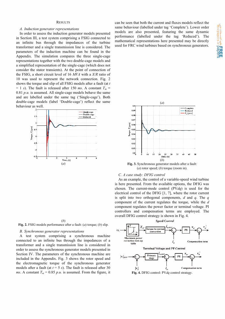
A. Induction generator representations In order to assess the induction generator models presented
in Section III, a test system comprising a FSIG connected to an infinite bus through the impedances of the turbine transformer and a single transmission line is considered. The parameters of the induction machine can be found in the Appendix. The simulation compares the three single-cage representations together with the two double-cage models and a simplified representation of the single-cage (which does not consider the stator transients). At the point of connection of the FSIG, a short circuit level of 16 MVA with a X/R ratio of 10 was used to represent the network connection. Fig. 2 shows the torque and slip of all FSIG models after a fault (at t = 1 s). The fault is released after 150 ms. A constant Tm = 0.81 p.u. is assumed. All single-cage models behave the same and are labelled under the same tag (‘Single-cage’). Both double-cage models (label ‘Double-cage’) reflect the same behaviour as well.
(a)
(b)
Fig. 2. FSIG models performance after a fault: (a) torque; (b) slip.
B. Synchronous generator representations A test system comprising a synchronous machine
connected to an infinite bus through the impedances of a transformer and a single transmission line is considered in order to assess the synchronous generator models presented in Section IV. The parameters of the synchronous machine are included in the Appendix. Fig. 3 shows the rotor speed and the electromagnetic torque of the synchronous generator models after a fault (at t = 5 s). The fault is released after 30 ms. A constant Tm = 0.85 p.u. is assumed. From the figure, it
can be seen that both the current and fluxes models reflect the same behaviour (labelled under tag ‘Complete’). Lower order models are also presented, featuring the same dynamic performance (labelled under the tag ‘Reduced’). The mathematical representations here presented may be directly used for FRC wind turbines based on synchronous generators.
(a)
(b)
Fig. 3. Synchronous generator models after a fault: (a) rotor speed; (b) torque (zoom in).
C. A case study: DFIG control As an example, the control of a variable-speed wind turbine
is here presented. From the available options, the DFIG was chosen. The current-mode control (PVdq) is used for the electrical control of the DFIG [1, 7], where the rotor current is split into two orthogonal components, d and q. The q component of the current regulates the torque, while the d component regulates the power factor or terminal voltage. PI controllers and compensation terms are employed. The overall DFIG control strategy is shown in Fig. 4.
Fig. 4. DFIG control: PVdq control strategy.

It is assumed that the power converters are ideal and that the DC link voltage between them is constant (in order to decouple them). Converter C1 has been modelled as a voltage source whereas C2 as a current source (refer to Fig. 1). For the simulations, both the double and single-cage models previously presented are employed.
An optimal torque set point is achieved from the torque-speed characteristic for a maximum power extraction [7]. The DFIG is connected to an infinite bus through the impedances of the turbine transformer and the transmission line. The protective over-current crowbar circuit is not considered for these simulations. The parameters of the induction machine and controllers are included in the Appendix.
Fig. 5 shows the DFIG responses for a 20% decrease in the mechanical torque input at t = 1 s. An initial mechanical torque Tm = 0.81 p.u. is assumed. As it can be seen, in both representations the terminal voltage remains at 1 p.u., with both the torque and slip reaching new values. It can be seen that both double and single-cage models respond adequately to the control system design.
Fig. 5. DFIG performance: 20% decrease in mechanical torque Tm.
Fig. 6. DFIG performance after a fault at t = 1 s with a duration of
150 ms.
Fig 6. shows the DFIG responses for a fault applied at t = 1 s with a duration of 150 ms. Due to the fault, the generator electrical torque falls to zero with the machine speeding up for both models. When the fault is cleared the system recovers its pre-fault state.
CONCLUSIONS
In this paper, the complete-order mathematical modelling of synchronous and induction generators for variable-speed wind turbine applications has been presented. Due to their compact and portable representations, the obtained state-space models are suitable for the inclusion in power system transient stability programs. Moreover, the modelling approach allows fully equivalent representations independen-tly of the chosen state variables. In particular, the so-called currents models are amenable for vector control schemes, where the control and output signals are voltages and currents, respectively. Simulation results are obtained using typical data and show that the developed models are in fact equivalent.
ACKNOWLEDGEMENTS
J.B.E. thanks the Low Carbon Research Institute (LCRI) for partly funding this work.
APPENDIX
A. Induction Generator Parameters [1, 2] Vb = 690 V, Sb = 2 MVA, b = 2fb. fb = 50 Hz, H = 3.5 s, Xtrans = 0.05 p.u.,
Rs = 0.00488 p.u., Xls = 0.09241 p.u., Rr = 0.00549 p.u., Xlr = 0.09955 p.u.,
Rd = 0.2696 p.u., Xld = 0.0453 p.u., Xm = 3.95279 p.u., Xrm = 0.02 p.u.
B. Synchronous Generator Parameters [8] Vb = 24 kV, Sb = 555 MVA, b = 2fb. fb = 50 Hz, H = 3.525 s,
Rs = 0.003 p.u., Xls= 0.015 p.u., Rfd = 0.0006 p.u., Xlfd = 0.165 p.u.,
Rkd = 0.0284 p.u., Xlkd = 0.1713 p.u., Rkq1 = 0.00619 p.u., Xlkq1 = 0.7252 p.u.,
Rkq2 = 0.02368 p.u., Xlkq2 = 0.125 p.u., Xdm = 1.66 p.u., Xqm = 1.61 p.u.
C. DFIG Control Parameters Cut-in speed = 1000 rpm, speed limit = 1800 rpm, shutdown speed = 2000
rpm [2]. KP,VC = KP,SC = 0.05, KI,VC = KI,SC = 10, KVC = 7.
REFERENCES [1] O. Anaya-Lara, N. Jenkins, J. B. Ekanayake, P. Cartwright, and M.
Hughes, Wind Energy Generation. Modelling and Control. UK: John Wiley and Sons, 2009.
[2] J. B. Ekanayake, L. Holdsworth, W. XueGuang, and N. Jenkins, "Dynamic modeling of doubly fed induction generator wind turbines," IEEE Transactions on Power Systems, vol. 18, pp. 803-809, 2003.
[3] V. Akhmatov, A. H. Nielsen, J. K. Pedersen, and O. Nymann, "Variable-speed wind turbines with multi-pole synchronous permanent magnet generators. Part I: Modelling in dynamic simulation tools," Wind Engineering, vol. 27, pp. 531-548, 2003.
[4] T. Ackermann, Wind Power in Power Systems. UK: John Wiley & Sons, 2005.
[5] P. Vas, Vector Control of AC Machines. USA: Oxford University Press, 1990.
[6] P. C. Krause, O. Wasynczuk, and S. D. Shudhoff, Analysis of Electric Machinery and Drive Systems. USA: John Wiley Press, 2002.
[7] R. Pena, J. C. Clare, and G. M. Asher, "Doubly fed induction generator using back-to-back PWM converters and its application to variable speed wind-energy generation," IEE Proceedings: Electric Power Applications, vol. 143, pp. 231-241, 1996.
[8] P. Kundur, Power Systems Stability and Control. USA: McGraw-Hill, 1994.