IEC Type Test Report Report No. EU1527-H-00.1 PH3 Series ... · accordance with procedures of IEC...
89
EU1527-H-00.1 IEC Type Test Report Report No. EU1527-H-00.1 PH3 Series Polymer-housed Arrester 10,000 A Line Discharge Class 3 This report records the results of type tests made on PH3 series 10 kA Line Discharge Class 3 arresters, rated up to 420 kV. Tests were performed in accordance with procedures of IEC Standard 60099-4, Ed. 2.1, 2006, “Surge arresters - Part 4: Metal-oxide surge arresters without gaps for a.c. systems.” To the best of our knowledge and within the usual limits of testing practice, tests performed on these arresters demonstrate compliance with the relevant clauses of the referenced standard. M. G. Comber Manager, Engineering Date: 8/24/2007 Separate reports provide details of each test, according to the following table: Report No. Description Clause Issue date EU1527-H-01 Insulation Withstand Test on Arrester Housing 10.8.2 9/29/2006 EU1527-H-02 Residual Voltage 10.8.3 9/29/2006 EU1527-H-03 Long Duration Current Withstand 10.8.4 9/29/2006 EU1527-H-04 Accelerated Aging Procedure 10.8.5 9/29/2006 EU1527-H-05 Heat Dissipation Behavior of Test Section 10.8.5 9/29/2006 EU1527-H-06 Switching Surge Operating Duty 10.8.5 9/29/2006 EU1527-H-07 Short Circuit 10.8.7 9/29/2006 EU1527-H-08 Internal Partial Discharge 10.8.8 9/29/2006 EU1527-H-09 Bending Moment 10.8.9 9/29/2006 EU1527-H-10 Seal Leak Rate 10.8.11 9/29/2006 EU1527-H-11 RIV 10.8.12 9/29/2006 EU1527-H-12 Moisture Ingress 10.8.13 9/29/2006 EU1527-H-13 Weather Ageing 10.8.14 9/29/2006 EU1527-H-14.1 Power Frequency Voltage Versus Time Annex D 8/24/2007
Transcript of IEC Type Test Report Report No. EU1527-H-00.1 PH3 Series ... · accordance with procedures of IEC...

EU1527-H-00.1
IEC Type Test ReportReport No. EU1527-H-00.1
PH3 Series Polymer-housed Arrester10,000 A Line Discharge Class 3
This report records the results of type tests made on PH3 series 10 kA LineDischarge Class 3 arresters, rated up to 420 kV. Tests were performed inaccordance with procedures of IEC Standard 60099-4, Ed. 2.1, 2006, “Surgearresters - Part 4: Metal-oxide surge arresters without gaps for a.c. systems.”
To the best of our knowledge and within the usual limits of testing practice, testsperformed on these arresters demonstrate compliance with the relevant clauses ofthe referenced standard.
M. G. ComberManager, Engineering
Date: 8/24/2007
Separate reports provide details of each test, according to the following table:Report No. Description Clause Issue date
EU1527-H-01 Insulation Withstand Test on Arrester Housing 10.8.2 9/29/2006EU1527-H-02 Residual Voltage 10.8.3 9/29/2006EU1527-H-03 Long Duration Current Withstand 10.8.4 9/29/2006EU1527-H-04 Accelerated Aging Procedure 10.8.5 9/29/2006EU1527-H-05 Heat Dissipation Behavior of Test Section 10.8.5 9/29/2006EU1527-H-06 Switching Surge Operating Duty 10.8.5 9/29/2006EU1527-H-07 Short Circuit 10.8.7 9/29/2006EU1527-H-08 Internal Partial Discharge 10.8.8 9/29/2006EU1527-H-09 Bending Moment 10.8.9 9/29/2006EU1527-H-10 Seal Leak Rate 10.8.11 9/29/2006EU1527-H-11 RIV 10.8.12 9/29/2006EU1527-H-12 Moisture Ingress 10.8.13 9/29/2006EU1527-H-13 Weather Ageing 10.8.14 9/29/2006
EU1527-H-14.1 Power Frequency Voltage Versus Time Annex D 8/24/2007

EU1527-H-01
1
IEC Type Test ReportReport No. EU1527-H-01
PH3 Series Polymer-housed Arrester10,000 A Line Discharge Class 3
Insulation Withstand Test on Arrester Housing
This report records the results of type tests made on PH3 series 10 kA LineDischarge Class 3 arresters, rated up to 420 kV. Tests were performed inaccordance with procedures of IEC Standard 60099-4, Ed. 2.1, 2006, “Surgearresters - Part 4: Metal-oxide surge arresters without gaps for a.c. systems.”
To the best of our knowledge and within the usual limits of testing practice, testsperformed on these arresters demonstrate compliance with the relevant clauses ofthe referenced standard.
M. G. ComberManager, Engineering
Date: 9/29/2006

EU1527-H-01
2
IEC TYPE TEST REPORTInsulation Withstand Test on Arrester Housing
TESTS PERFORMED:Insulation withstand tests were made on one arrester unit with internal componentsremoved, in accordance with the requirements of clause 10.8.2 of IEC 60099-4. It isrequired that the external insulation withstand of the arrester housing conforms to thefollowing:
• Lightning impulse withstand voltage in dry conditions shall not be less than thelightning impulse protective level of the arrester unit multiplied by 1.3.
• Switching impulse withstand voltage in wet conditions shall not be less than theswitching impulse protective level of the arrester unit multiplied by 1.25.
• Power frequency withstand voltage (peak value) in wet conditions shall not beless than the switching impulse protective level of the arrester unit multiplied by1.06 for a duration of 1 min.
RESULTS:
The PH3 series of arresters use four different housing lengths, all using the sameweathershed geometry. The insulation withstand tests were performed on a sampleconstructed with the longest housing. The highest Uc used in this housing is 120 kV, forwhich the lightning impulse protective level is 358 kV at 10kA, and the maximumswitching impulse protective level is 296 kV at 1kA.
Lightning impulseThe lightning impulse test was performed under dry conditions by applying 15 positiveand 15 negative full-wave lightning-impulse voltages to the test sample. The impulsevoltages had a virtual front time of 1.2 µs (±30%) and a virtual time to half value of 50µs (±20%). The test sample withstood all impulses without disruptive discharge. Thewithstand voltages obtained were corrected to standard atmospheric conditions inaccordance with IEC 60060-1.
The required minimum lightning impulse withstand voltage is 1.3 times the maximumlightning impulse protective level, or 1.3 x 358 = 466 kV.
Switching impulseThe switching impulse test was performed under wet conditions by applying 15 positiveand 15 negative full-wave switching-impulse voltages to the test sample. Theprecipitation conditions and resistivity of the water were in accordance with therequirements of IEC 60060-1. The impulse voltages had a time to crest value of 250 µs(±20%) and a time to half value of 2500 µs (±60%). The test sample withstood allimpulses without disruptive discharge. The withstand voltages obtained were correctedto standard atmospheric conditions in accordance with IEC 60060-1.

EU1527-H-01
3
The required minimum switching impulse withstand voltage is 1.25 times the maximumswitching impulse protective level, or 1.25 x 296 = 370 kV.
Power frequencyThe power frequency test was performed under wet conditions by applying a 60 Hzvoltage for a duration of 1 min. The precipitation conditions and resistivity of the waterwere in accordance with the requirements of IEC 60060-1. The test sample withstood theapplied voltage without disruptive discharge.
The required minimum power frequency withstand voltage is 1.06 times the maximumswitching impulse protective level, or 1.06 x 296 = 312 kVpeak.
Tests were successfully performed at levels higher that exceeded the minimum levelsindicated above. Results are summarized in Table 1.
Table 1. Measured and corrected withstand values
Atmospheric conditions Correction factorsUncorrectedwithstand
voltageAmbient
temperature
Airpressure
Absolutehumidity
Airdensity Humidity
CorrectedwithstandWithstand test
kV pk oC KPa gm-3 k1 k2 kV peakLightningimpulse, pos 669 27.2 97.9 13.3 .943 1.027 690
Lightningimpulse, neg 830 18.4 97.9 11.8 .971 1.005 850
Switchingimpulse, pos 500 18.7 98.1 Wet test -- 1.000 500
Switchingimpulse, neg 634 18.7 98.1 Wet test -- 1.000 634
60 Hz 355 18.6 98.0 Wet test -- 1.000 355

EU1527-H-02
1
IEC Type Test ReportReport No. EU1527-H-02
PH3 Series Polymer-housed Arrester10,000 A Line Discharge Class 3
Residual Voltage
This report records the results of type tests made on PH3 series 10 kA LineDischarge Class 3 arresters, rated up to 420 kV. Tests were performed inaccordance with procedures of IEC Standard 60099-4, Ed. 2.1, 2006, “Surgearresters - Part 4: Metal-oxide surge arresters without gaps for a.c. systems.”
To the best of our knowledge and within the usual limits of testing practice, testsperformed on these arresters demonstrate compliance with the relevant clauses ofthe referenced standard.
M. G. ComberManager, Engineering
Date: 9/29/2006

EU1527-H-02
2
IEC TYPE TEST REPORTResidual Voltage
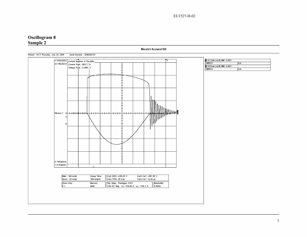
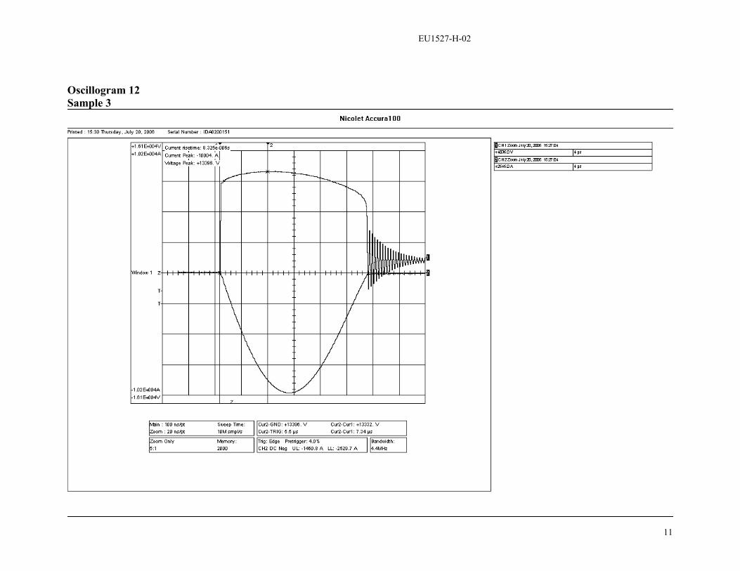
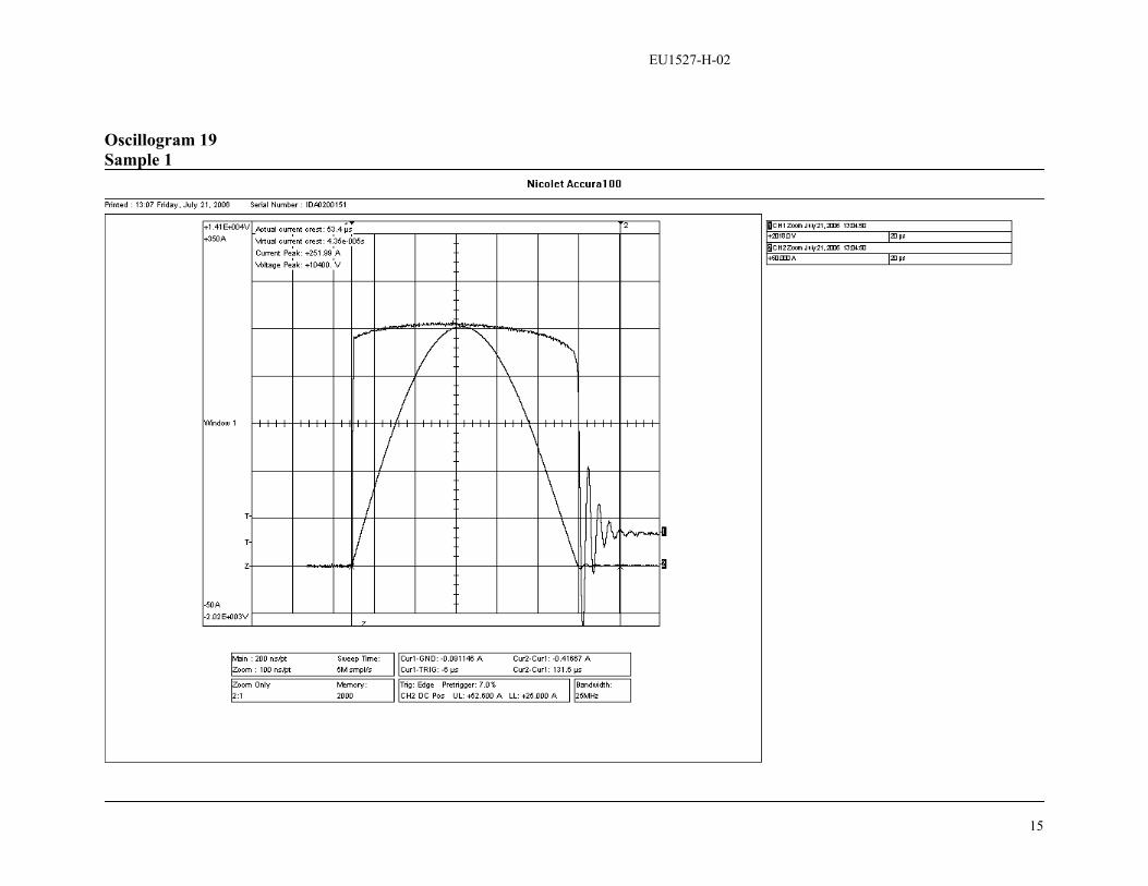
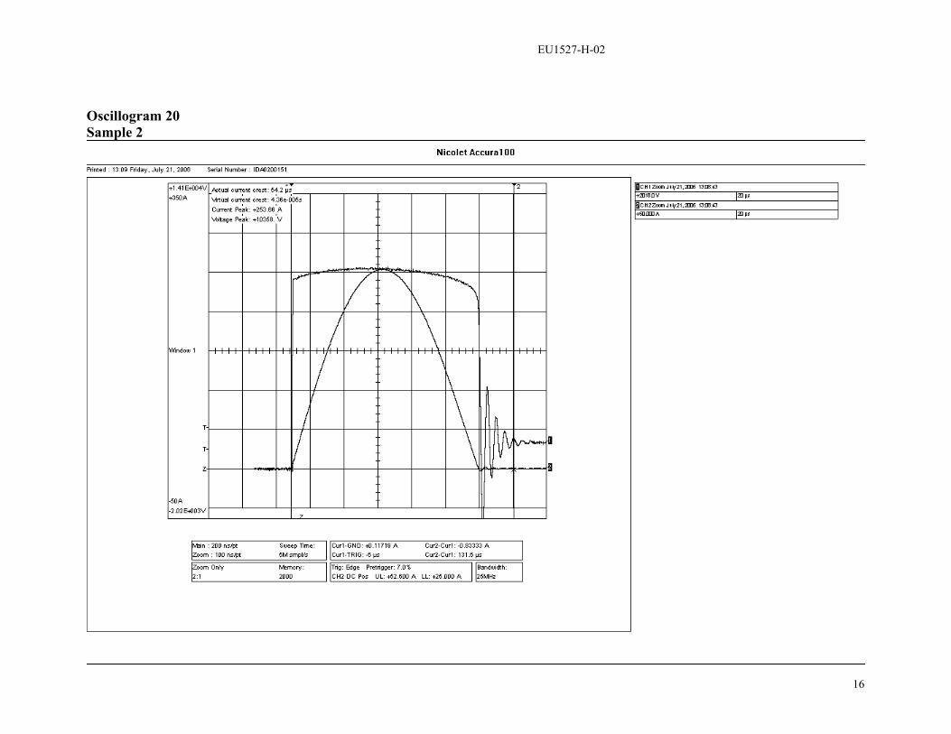
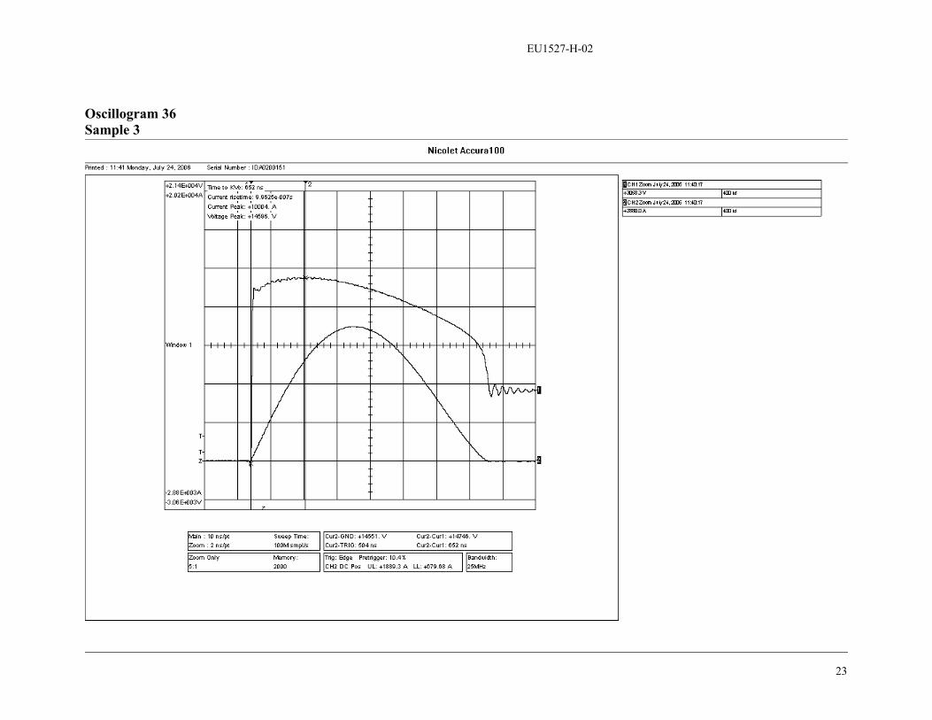
TESTS PERFORMED:Residual voltage measurements were made on three single resistor elements. Tests wereconducted in accordance with clause 10.8.3 of IEC 60099-4, to determine steep currentimpulse residual voltages at 10 kA, lightning impulse residual voltages at 5 kA, 10 kAand 20 kA, and switching impulse residual voltages at 0.25 kA and 1 kA. Oscillogramsof current and voltage were obtained for each test.
For each test sample, all measured voltages have been rationalized to the lightningimpulse residual voltage of that sample at nominal discharge current (10 kA 8/20), andthe results have been displayed in graphical form.
RESULTS:Tables 1, 2 and 3 show the residual voltages measured on test samples 1, 2 and 3,respectively. For each test sample, the measured residual voltages have been expressedin per unit of the lightning impulse residual voltage at nominal discharge current (10 kA,8/20).
Table 1. Measurements made on test sample 1
Currentmagnitude Waveshape Residual Voltage OscillogramTest Wave
kA _s kV p.u. numberSteepcurrent 10 1/2 14.583 1.090 34
5 12.471 0.932 710 13.385 1.000 10Lightning
impulse20
8/2014.452 1.080 13
0.25 43/91 10.040 0.777 19Switchingimpulse 1 40/86 11.050 0.826 25
Table 2. Measurements made on test sample 2
Currentmagnitude Waveshape Residual Voltage OscillogramTest wave
kA _s kV p.u. numberSteepcurrent 10 1/2 14.545 1.087 35
5 12.465 0.932 810 13.380 1.000 11Lightning
impulse20
8/2014.436 1.079 14
0.25 43/91 10.358 0.774 20Switchingimpulse 1 40/86 11.050 0.826 26
EU1527-H-02
3
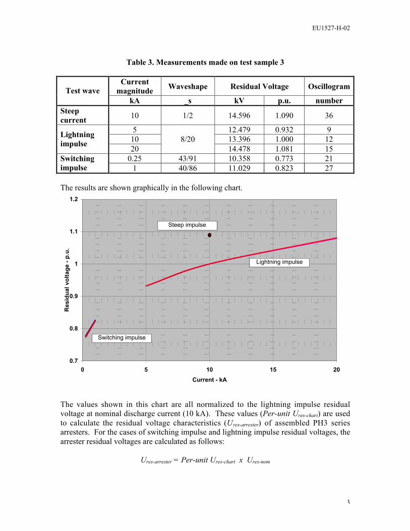
Table 3. Measurements made on test sample 3
Currentmagnitude Waveshape Residual Voltage OscillogramTest wave
kA _s kV p.u. numberSteepcurrent 10 1/2 14.596 1.090 36
5 12.479 0.932 910 13.396 1.000 12Lightning
impulse 208/20
14.478 1.081 150.25 43/91 10.358 0.773 21Switching
impulse 1 40/86 11.029 0.823 27
The results are shown graphically in the following chart.
The values shown in this chart are all normalized to the lightning impulse residualvoltage at nominal discharge current (10 kA). These values (Per-unit Ures-chart) are usedto calculate the residual voltage characteristics (Ures-arrester) of assembled PH3 seriesarresters. For the cases of switching impulse and lightning impulse residual voltages, thearrester residual voltages are calculated as follows:
Ures-arrester = Per-unit Ures-chart x Ures-nom
0.7
0.8
0.9
1
1.1
1.2
0 5 10 15 20Current - kA
Res
idua
l vol
tage
- p.
u.
Steep impulse
Lightning impulse
Switching impulse

EU1527-H-02
4
where Ures-nom is the published maximum lightning impulse residual voltage of thearrester, as verified by routine test at time of arrester manufacture.
For the case of steep current impulse residual voltage, the arrester residual voltage iscalculated as follows:
Ures-arrester = Per-unit Ures-chart x Ures-nom + L’ h In / Tf
whereL’ is the inductivity per unit length (= 1 µH/m)h is the length of the arrester (excluding the resistors since resistor inductance is alreadyincluded in the test measurements)In is the nominal discharge current (= 10 kA)Tf is the front time of the steep current impulse (= 1µs)
EU1527-H-02
5
Oscillograms

EU1527-H-02
6
Oscillogram 7Sample 1
EU1527-H-02
7
Oscillogram 8Sample 2

EU1527-H-02
8
Oscillogram 9Sample 3

EU1527-H-02
9
Oscillogram 10Sample 1

EU1527-H-02
10
Oscillogram 11Sample 2
EU1527-H-02
11
Oscillogram 12Sample 3

EU1527-H-02
12
Oscillogram 13Sample 1

EU1527-H-02
13
Oscillogram 14Sample 2

EU1527-H-02
14
Oscillogram 15Sample 3
EU1527-H-02
15
Oscillogram 19Sample 1
EU1527-H-02
16
Oscillogram 20Sample 2

EU1527-H-02
17
Oscillogram 21Sample 3

EU1527-H-02
18
Oscillogram 25Sample 1

EU1527-H-02
19
Oscillogram 26Sample 2

EU1527-H-02
20
Oscillogram 27Sample 3

EU1527-H-02
21
Oscillogram 34Sample 1

EU1527-H-02
22
Oscillogram 35Sample 2
EU1527-H-02
23
Oscillogram 36Sample 3

EU1527-H-03
IEC Type Test ReportReport No. EU1527-H-03
PH3 Series Polymer-housed Arrester10,000 A Line Discharge Class 3
Long Duration Current Impulse Withstand Tests
This report records the results of type tests made on PH3 series 10 kA LineDischarge Class 3 arresters, rated up to 420 kV. Tests were performed inaccordance with procedures of IEC Standard 60099-4, Ed. 2.1, 2006, “Surgearresters - Part 4: Metal-oxide surge arresters without gaps for a.c. systems.”
To the best of our knowledge and within the usual limits of testing practice, testsperformed on these arresters demonstrate compliance with the relevant clauses ofthe referenced standard.
M.G. ComberManager, Engineering
Date: 9/29/2006

EU1527-H-03
- 2 -
IEC TYPE TEST REPORTLong Duration Current Impulse Withstand Tests
TESTS PERFORMED:Long duration current impulse withstand tests were performed on three test samples,each consisting of two resistors (75 mm diameter, 44 mm long) in series. The resistorswere selected to represent the lowest acceptable reference voltage level. The tests wereconducted in accordance with clause 10.8.4 of IEC 60099-4. Prior to the administering ofline discharges, measurements were made of the residual voltage and reference voltage oneach test sample. The transmission line parameters conformed to the requirements forLine Discharge Class 4 in Table 5 of IEC 60099-4.
Table 1 lists the parameters of the test sections and the corresponding transmission lineparameters used for the test. Uc for the PH3 series of arresters has been established as0.795 times the lowest acceptable reference voltage in routine tests, and Ur has beenestablished as 1.25 times Uc . This would normally be represented in the type test byassigning the test sample Uc equal to 0.795 x Uref of the test sample, and test sample Ur at1.25 times this value . However, in this particular test, Uc was set at a higher value thanthat used in the actual design (specifically, 0.81 x Uref), thereby making the test moreonerous. The minimum energy required for each line discharge for Class 3 arresters isdetermined from the following formula given in Clause 8.4.2 of IEC 60099-4
W = Ures x (UL – Ures) x 1/Z x T
where Ures is the switching impulse residual voltage at 250 A.
Table 1. Parameters for Line Discharge Tests
Parameter Sample 1 Sample 2 Sample 3Switching impulse residual voltage (kV) UresInitial Residual Voltage (kV) @ 10 kA, 8/20Reference Current (mA) IrefReference Voltage (kVc / √2) VrefCOV ( kV rms) UcRating (kV rms) UrArrester Classification (kA)Line Discharge ClassVirtual Duration of Peak (µs, 90-90%) - minSurge Impedance (Ω) Zg - max (1.3 Ur)Charging Voltage (kV) UL – min (2.8 Ur)Energy required (kJ) - min
20.6226.679.5
11.519.3311.66
103
2 40015.1632.6539.3
20.5626.679.5
11.519.3211.65
103
2 40015.1532.6239.3
20.6426.659.5
11.509.3211.65
103
2 40015.1532.6239.3
EU1527-H-03
- 3 -
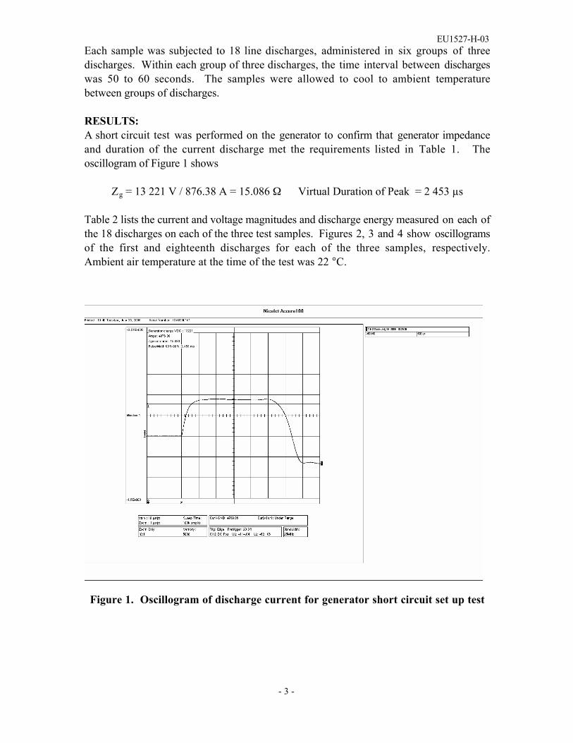
Each sample was subjected to 18 line discharges, administered in six groups of threedischarges. Within each group of three discharges, the time interval between dischargeswas 50 to 60 seconds. The samples were allowed to cool to ambient temperaturebetween groups of discharges.
RESULTS:A short circuit test was performed on the generator to confirm that generator impedanceand duration of the current discharge met the requirements listed in Table 1. Theoscillogram of Figure 1 shows
Zg = 13 221 V / 876.38 A = 15.086 Ω Virtual Duration of Peak = 2 453 µs
Table 2 lists the current and voltage magnitudes and discharge energy measured on each ofthe 18 discharges on each of the three test samples. Figures 2, 3 and 4 show oscillogramsof the first and eighteenth discharges for each of the three samples, respectively. Ambient air temperature at the time of the test was 22 °C.
Figure 1. Oscillogram of discharge current for generator short circuit set up test

EU1527-H-03
- 4 -
Table 2. Line Discharge Test Measurements
Sample 1 Sample 2 Sample 3Impulse
I (A) V(kV)
E (kJ) I (A) V
(kV) E (kJ) I(A)
V (kV)
E (kJ)
1 711 22.18 45.0 765 21.45 46.7 763 21.43 47.12 738 21.83 45.9 747 21.78 46.4 742 21.88 46.33 717 22.16 45.3 721 22.14 45.7 721 22.22 45.74 772 21.51 47.2 774 21.47 47.2 767 21.51 47.05 738 21.83 45.9 751 21.85 46.5 740 21.91 46.26 744 21.89 46.5 717 22.20 45.7 719 22.28 45.57 763 21.51 47.0 763 21.49 46.8 761 21.53 46.98 742 21.93 46.1 736 21.87 46.1 738 21.93 46.09 719 22.26 45.5 717 22.16 45.4 717 22.24 45.4
10 717 22.42 45.4 772 21.45 46.9 759 21.53 46.711 740 21.89 46.1 736 21.89 46.0 740 21.88 46.012 717 22.20 45.5 715 22.20 45.5 719 231.88 45.213 763 21.51 46.9 763 21.47 46.9 761 21.53 46.814 738 21.93 46.0 736 21.91 46.1 736 21.89 45.915 717 22.24 45.4 715 22.24 45.5 717 22.28 45.416 779 21.56 47.8 770 21.47 47.2 764 21.56 47.017 752 21.97 46.9 745 21.85 46.5 745 21.95 46.318 724 22.31 46.1 722 22.18 45.8 714 22.24 45.6
Subsequent to the completion of the transmission line discharges, the residual voltage atnominal discharge current was re-measured and compared to the initial values for each testsample. Results are summarized in Table 3. The maximum change of residual voltage ofthe three samples is less than the permissible change of 5 % defined by IEC 60099-4.
Table 3. Initial and final residual voltage measurements
Residual voltage (kV)Sample
Before AfterChange
1 26.67 26.65 - 0.08%2 26.67 26.60 - 0.27%3 26.65 26.65 0%
Disassembly of the test samples at the end of the electrical tests revealed no evidence ofphysical damage.

EU1527-H-03
- 5 -
Sample 1, Discharge 1
Sample 1, Discharge 18
Figure 2. Oscillograms of line discharges for sample 1

EU1527-H-03
- 6 -
Sample 2, Discharge 1
Sample 2, Discharge 18
Figure 3. Oscillograms of line discharges for sample 2

EU1527-H-03
- 7 -
Sample 3, Discharge 3
Sample 3, Discharge 18
Figure 4. Oscillograms of line discharges for sample 3

EU1527-H-04
IEC Type Test ReportReport No. EU1527-H-04
PH3 Series Polymer-housed Arrester10,000 A Line Discharge Class 3
Accelerated Aging Procedure
This report records the results of type tests made on PH3 series 10 kA LineDischarge Class 3 arresters, rated up to 420 kV. Tests were performed inaccordance with procedures of IEC Standard 60099-4, Ed. 2.1, 2006, “Surgearresters - Part 4: Metal-oxide surge arresters without gaps for a.c. systems.”
To the best of our knowledge and within the usual limits of testing practice, testsperformed on these arresters demonstrate compliance with the relevant clauses ofthe referenced standard.
M.G. ComberManager, Engineering
Date: 9/29/2006

EU1527-H-04
- 2 -
IEC TYPE TEST REPORTAccelerated Ageing Procedure
TESTS PERFORMED:Accelerated aging tests were performed on three resistor elements, each 56mm diameterand 41mm long. The tests were conducted in accordance with the requirements of clause10.8.5 of IEC 60099-4 (requiring the accelerated ageing procedure of clause 8.5.2 to beadministered). The test samples were placed in an air oven and energized at a voltageequal to the corrected maximum continuous operating voltage, Uct , for 1000 hours. Uct isthe voltage that corresponds to the maximum voltage to which a resistor would besubjected in a complete arrester, taking into account non-uniform voltage distributionalong the arrester length. PH3 arresters are designed such that the maximum voltage stressat any point along the resistor column is not more than 1.15 times the average stress alongthe column.
The temperature of the samples was maintained at 115 °C ± 2 °C for the duration of thetest.
Power dissipation was measured on each sample throughout the 1000 h test period.
Clause 8.5.2 of IEC 60099-4 defines three power dissipation values:• P1ct , measured 1 h to 2 h after the initial voltage application• P2ct , measured after 1000 h• P3ct , the minimum value attained during the 1000 h test period.
If P2ct is equal to or less than 1.1 times P3ct , then the switching surge operating duty testof Clause 8.5.5 of IEC 6099-4 is to be performed on new resistors. Furthermore, if P2ct isequal to or less than P1ct , then the rated voltage and continuous operating voltage used forthe operating duty test are not subject to any modification.
RESULTS:Table 1 lists sample characteristics and calculated minimum test voltage Uct . The testvoltage was set to 5.30 kVrms
Table 1. Parameters for accelerated ageing test
Sample 1 Sample 2 Sample 3Reference current - mA 9.5 9.5 9.5Reference voltage, Uref – kVpk/√2 5.76 5.75 5.74Uc (0.795 x Uref) - kVrms 4.58 4.57 4.56Uct (1.15 x Uc) - kVrms 5.27 5.26 5.25

EU1527-H-04
- 3 -
Figure 1 graphically displays the measurements made during the 1000 h test period.Table 1 summarizes the values of P1ct, P2ct and P3ct for each sample. The requirementsthat P2ct is equal to or less than 1.1 times P3ct , and P2ct is equal to or less than P1ct are metfor all three samples. Consequently, no modification needs to be made to the ratedvoltage and continuous operating voltage in the operating duty test, and the operatingduty test can be performed on new resistors.
Table 1. Power dissipation values
Power dissipationat 2 h
Power dissipationat 1000 h
Minimum powerdissipationSample
NumberP1ct (W) P2c t (W) P3ct (W)
1 6.39 4.11 4.112 6.36 4.11 4.113 6.17 4.01 4.01
0
2
4
6
8
10
12
0 200 400 600 800 1000Time - min
Pow
er d
issi
patio
n - W
App
lied
volta
ge -
kVrm
s
0
20
40
60
80
100
120
Tem
pera
ture
- C
Temperature
Voltage
Power dissipation of samples
Figure 1. Power dissipation, voltage and temperature measurementsduring 1000 h test period
EU1527-H-05
IEC Type Test ReportReport No. EU1527-H-05
PH3 Series Polymer-housed Arrester10,000 A Line Discharge Class 3
Heat Dissipation Behaviour of Test Section
This report records the results of type tests made on PH3 series 10 kA LineDischarge Class 3 arresters, rated up to 420 kV. Tests were performed inaccordance with procedures of IEC Standard 60099-4, Ed. 2.1, 2006, “Surgearresters - Part 4: Metal-oxide surge arresters without gaps for a.c. systems.”
To the best of our knowledge and within the usual limits of testing practice, testsperformed on these arresters demonstrate compliance with the relevant clauses ofthe referenced standard.
M.G. ComberManager, Engineering
Date: 9/29/2006

EU1527-H-05
- 2 -
IEC TYPE TEST REPORTHeat Dissipation Behaviour of Test Section
TESTS PERFORMED:Tests were performed as required by clause 10.8.5 and Annex B of IEC 60099-4, tocompare the cooling characteristics of the test section used for type tests with those of afull-size arrester unit. For this purpose, a specially modified arrester unit withUr = 150 kV unit and a test section with Ur = 10.6 kV were prepared. The 150 kV ratedunit, which represents the highest individual unit rated voltage and the most resistors perunit length of all units used in the arrester design, was equipped with thermocoupleslocated at one-third (top), one-half (middle) and two-thirds (bottom) positions along theunit length. The test section was comprised of two resistor elements (56 mm diameter,41 mm long) assembled into a short section of polymeric housing, insulated on top andbottom ends to control the rate of cooling to meet the requirements that the test sectioncools at a rate not greater than that of the assembled unit. A thermocouple was located atthe mid-height of the two-resistor stack
Both assembled unit and test section were heated electrically with a power frequencyovervoltage to raise the average temperature of the resistors to 120oC in the same amountof time. The voltage was removed and the samples allowed to cool naturally.Temperature measurements were made throughout the cooling period.
RESULTS:The resistors in both the assembled unit and the test section were heated by applying avoltage sufficiently above Ur to raise the resistor temperature to 120oC in approximately4 min. Figure 1 graphically displays the cooling of both samples over a period ofapproximately 3.5 hours.
With both samples starting from the same initial temperature of 120oC, the temperatureof the resistors in the test section above the temperature of the resistors in the fullyassembled unit throughout the cooling period. This demonstrates the validity of the testsection for use in type tests involving thermal recovery.

EU1527-H-05
- 3 -
Figure 1. Cooling curves of fully assembled arrester unit and test section
0
20
40
60
80
100
120
140
0 50 100 150 200 250Time (min)
Tem
pera
ture
(C
)
Arrester TopArrester MiddleArrester BottomSection
EU1527-H-06
IEC Type Test ReportReport No. EU1527-H-06
PH3 Series Polymer-housed Arrester10,000 A Line Discharge Class 3
Switching Surge Operating Duty Test
This report records the results of type tests made on PH3 series 10 kA LineDischarge Class 3 arresters, rated up to 420 kV. Tests were performed inaccordance with procedures of IEC Standard 60099-4, Ed. 2.1, 2006, “Surgearresters - Part 4: Metal-oxide surge arresters without gaps for a.c. systems.”
To the best of our knowledge and within the usual limits of testing practice, testsperformed on these arresters demonstrate compliance with the relevant clauses ofthe referenced standard.
M.G. ComberManager, Engineering
Date: 9/29/2006

EU1527-H-06
- 2 -
IEC TYPE TEST REPORTSwitching Surge Operating Duty Test
TESTS PERFORMED:Switching surge operating duty tests, in accordance with the requirements of clause 10.8.5of IEC 60099-4, were performed on three prorated test sections. The test sections wereprepared based on the results of the tests to verify heat dissipation behaviour of testsample (see EU1527-H-05 section of PH3 type test report). Each section consisted oftwo resistors (56 mm diameter, 41 mm long) in series. The resistors were selected torepresent the lowest acceptable reference voltage level. Prior to the conditioning portionof the test, measurements were made of the lightning impulse residual voltage of eachsection, and also of reference voltage of each section.
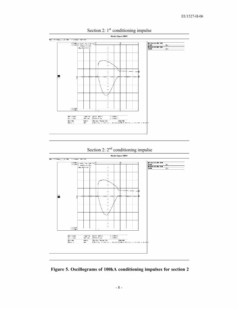
The conditioning portion of the test consisted of two parts. In the first part, a series oftwenty 8/20 lightning current impulses was applied to each section, with peak value ofthe impulses being equal to the nominal discharge current. The series of impulses wasdivided into four groups of five, with the interval between impulses within each groupbeing between 50 and 60 seconds and the interval between groups being between 25 and30 minutes. Test sections were energized at 60 Hz voltage of 1.2 × Uc during theapplication of the impulses within each group. The impulses were timed to occur 60°before the crest of the 60 Hz voltage with the same polarity of the impulse. In the secondpart, a series of two 100kA 4/10 impulses were applied to each section, with the sectionallowed to cool to ambient temperature between impulses.
Following the conditioning portion of the test, each section was placed in an oven andheated overnight to 60 ± 3 °C. After removal from the oven, each section was subjectedto two long duration current impulses, with time between impulses being between 50 and60 seconds. The parameters of the transmission line used to generate these impulsesconformed to the requirements for Line Discharge Class 4 in Table 5 of Clause 8.4.2 ofIEC 60099-4. Within 100 milliseconds of the second long duration current impulse, ratedvoltage (Ur) was applied to each section for 10 seconds, immediately followed by Uc for30 minutes, during which period the power dissipation was monitored to verify thermalstability.
At the end of the above test sequence, each section was allowed to cool to ambienttemperature, at which point the lightning impulse residual voltage at nominal dischargecurrent was re-measured.
Table 1 lists the parameters of the test sections and the corresponding transmission lineparameters used for the test. Uc for the PH3 series of arresters has been established as0.795 times the lowest acceptable reference voltage in routine tests, and Ur has beenestablished as 1.25 times Uc . This is represented in this type test by assigning the test

EU1527-H-06
- 3 -
sample Uc equal to 0.795 x Uref of the test sample, and test sample Ur at 1.25 times thisvalue . The minimum energy required for each line discharge for Class 3 arresters isdetermined from the following formula given in Clause 8.4.2 of IEC 60099-4
W = Ures x (UL – Ures) x 1/Z x T
where Ures is the switching impulse residual voltage at 250 A.
Table 1. Initial Measurements and Parameters for Line Discharge TestsParameter Sample 1 Sample 2 Sample 3
Switching impulse residual voltage (kV) UresInitial Residual Voltage (kV) @ 20 kA, 8/20Reference Current (mA) IrefReference Voltage (kVc / √2) VrefCOV ( kV rms) UcRating (kV rms) UrArrester Classification (kA)Line Discharge ClassVirtual Duration of Peak (µs, 90-90%) - minSurge Impedance (Ω) Zg - max (1.3 Ur)Charging Voltage (kV) UL – min (2.8 Ur)Energy required (kJ) - min
20.6426.719.5
11.519.1511.44
103
240014.8732.0338.0
20.6426.719.5
11.519.1511.44
103
240014.8732.0338.0
20.6426.709.5
11.509.1411.43
103
240014.8732.0038.0
RESULTS:Figures 1, 2 and 3 show recordings made during application of the 1st and 20th lightningimpulse conditioning discharges on each section. Figures 4, 5 and 6 show recordings madeduring application of the 1st and 2nd high current conditioning impulse on each section.
A short circuit test was performed on the generator to confirm that generator impedanceand duration of the current discharge met the requirements listed in Table 1. Theoscillogram of Figure 7 shows
Zg = 10 708 V / 728.09 A = 14.707 Ω Virtual Duration of Peak = 2 457 µs
Table 2 lists the current and voltage magnitudes and discharge energy measured on each ofthe two line discharges for each of the three test samples.
Table 2. Line Discharge Test MeasurementsSection 1 Section 2 Section 3
Impulse I(A)
V(kV)
E(kJ) I (A) V
(kV)E
(kJ)I
(A)V
(kV)E
(kJ)1 639 21.71 39.6 636 21.72 39.6 627 21.71 39.22 617 22.01 38.9 615 22.01 38.9 606 21.96 38.2

EU1527-H-06
- 4 -
Section 1: 1st conditioning impulse
Section 1: 20th conditioning impulse
Figure 1. Oscillograms of 10kA 8/20 conditioning impulses for section 1

EU1527-H-06
- 5 -
Section 2: 1st conditioning impulse
Section 2: 20th conditioning impulse
Figure 2. Oscillograms of 10kA 8/20 conditioning impulses for section 2

EU1527-H-06
- 6 -
Section 3: 1st conditioning impulse
Section 3: 20th conditioning impulse
Figure 3. Oscillograms of 10kA 8/20 conditioning impulses for section 3

EU1527-H-06
- 7 -
Section 1: 1st conditioning impulse
Section 1: 2nd conditioning impulse
Figure 4. Oscillograms of 100kA conditioning impulses for section 1
EU1527-H-06
- 8 -
Section 2: 1st conditioning impulse
Section 2: 2nd conditioning impulse
Figure 5. Oscillograms of 100kA conditioning impulses for section 2

EU1527-H-06
- 9 -
Section 3: 1st conditioning impulse
Section 3: 2nd conditioning impulse
Figure 6. Oscillograms of 100kA conditioning impulses for section 3

EU1527-H-06
- 10 -
Figure 7. Oscillogram of discharge current for generator short circuit set up test
Figures 8, 9 and 10 show oscillograms of the second line discharge and the 10 sapplication of Ur on each section. Ambient air temperature at the time of the test was 22°C. Table 3 lists measurements made during this period.
Table 3. Measurements made during 10 s application of Ur.
Section 1 Section 2 Section 3Time
(s)Voltage(kVc)
Current(mAc)
Time(s)
Voltage(kVc)
Current(mAc)
Time(s)
Voltage(kVc)
Current(mAc)
0 16.17 98 0 16.16 118 0 16.28 1301 16.31 101 1 16.33 119 1 16.52 1302 16.35 101 2 16.39 119 2 16.55 1314 16.37 101 4 16.39 117 4 16.55 1276 16.35 103 6 16.38 116 6 16.55 1278 16.37 105 8 16.39 119 8 16.57 133
10 16.34 103 10 16.40 123 10 16.56 133Avg rmsvoltageduring
10s
11.55 kV Avg rmsvoltageduring
10s
11.57 kV Avg rmsvoltageduring
10s
11.69 kV

EU1527-H-06
- 11 -
Figure 8. Oscillogram of second line discharge for section 1
Figure 9. Oscillogram of second line discharge for section 2

EU1527-H-06
- 12 -
Figure 10. Oscillogram of second line discharge for section 3
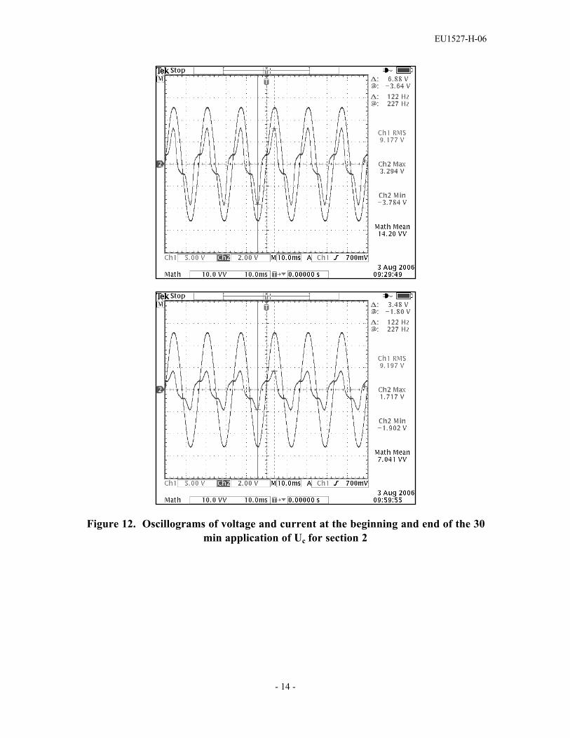
Figures 11, 12 and 13 show oscillograms of voltage and current at the beginning and end ofthe 30 min application of Uc on each section. Table 4 lists measurements of powerdissipation made during this period.
Table 4. Measurements of power dissipation made during 30 min at Uc
Power Dissipation (W)Time (min)Section 1 Section 2 Section 3
0 28.5 31.8 26.80.5 25.7 27.8 24.31 24.1 27.5 23.02 22.3 25.4 20.55 18.5 23.0 17.110 15.5 20.7 15.020 12.5 17.9 11.230 10.1 15.7 9.2

EU1527-H-06
- 13 -
Figure 11. Oscillograms of voltage and current at the beginning and end of the 30min application of Uc for section 1
EU1527-H-06
- 14 -
Figure 12. Oscillograms of voltage and current at the beginning and end of the 30min application of Uc for section 2

EU1527-H-06
- 15 -
Figure 13. Oscillograms of voltage and current at the beginning and end of the 30min application of Uc for section 3

EU1527-H-06
- 16 -
Subsequent to the completion of the thermal recovery, and after the sections had cooledto ambient temperature, the residual voltage at nominal discharge current was re-measuredand compared to the initial values for each test sample. Results are summarized in Table5. The maximum change of residual voltage of the three samples is less than thepermissible change of 5 % defined by IEC 60099-4.
Table 5. Initial and final residual voltage measurements
Residual voltage (kV)Section
Initial FinalChange
1 26.712 27.017 + 1.1 %2 26.712 26.965 + 0.9 %3 26.702 27.101 + 1.5 %
Disassembly of the test samples at the end of the electrical tests revealed no evidence ofphysical damage.
EU1527-H-07
- 1 -
IEC Type Test ReportReport No. EU1527-H-07
PH3 Series Polymer-housed Arrester10,000 A Line Discharge Class 3
Short Circuit
This report records the results of type tests made on PH3 series 10 kA LineDischarge Class 3 arresters, rated up to 420 kV. Tests were performed inaccordance with procedures of IEC Standard 60099-4, Ed. 2.1, 2006, “Surgearresters - Part 4: Metal-oxide surge arresters without gaps for a.c. systems.”
To the best of our knowledge and within the usual limits of testing practice, testsperformed on these arresters demonstrate compliance with the relevant clauses ofthe referenced standard.
M.G. ComberManager, Engineering
Date: 9/29/2006

EU1527-H-07
- 2 -
IEC TYPE TEST REPORTShort Circuit
TESTS PERFORMED:The PH3 series of arresters has a rated short circuit capability of 63 000 A symmetrical.The physical design of the PH3 arresters is identical to that of PH4 arresters in allrespects except for the diameter of the resistor elements. The PH3 arrester uses 56mmdiameter resistors, compared to 75mm diameter resistors for PH4. High current shortcircuit tests were performed at the CESI high power laboratory in Milan, Italy on PH4arrester units. These tests are sufficient to qualify also the PH3 arrester, because thereduced amount of internal air space in the PH4 design makes the test of PH4 moresevere. Tests were made according to the procedures described in Amendment 1, Clause10.8.7, of IEC 60099-4. . Verification of capability requires three high current tests,performed with rated short circuit current (63 000 A) and two reduced short circuitcurrents (25 000 A and 12 000 A). For these tests, fully assembled test units wereprepared, each containing as many resistor elements as possible within the availablestacking length. The internal elements of each test unit were shorted by a fuse wirerunning along the outside of the stack of elements. The units tested represented thelongest mechanical unit used in the PH3 and PH4 series of arresters.
RESULTS:Complete results of the testing are contained in a CESI test report that is available onrequest. Results are summarized in the following extracts from the CESI report.
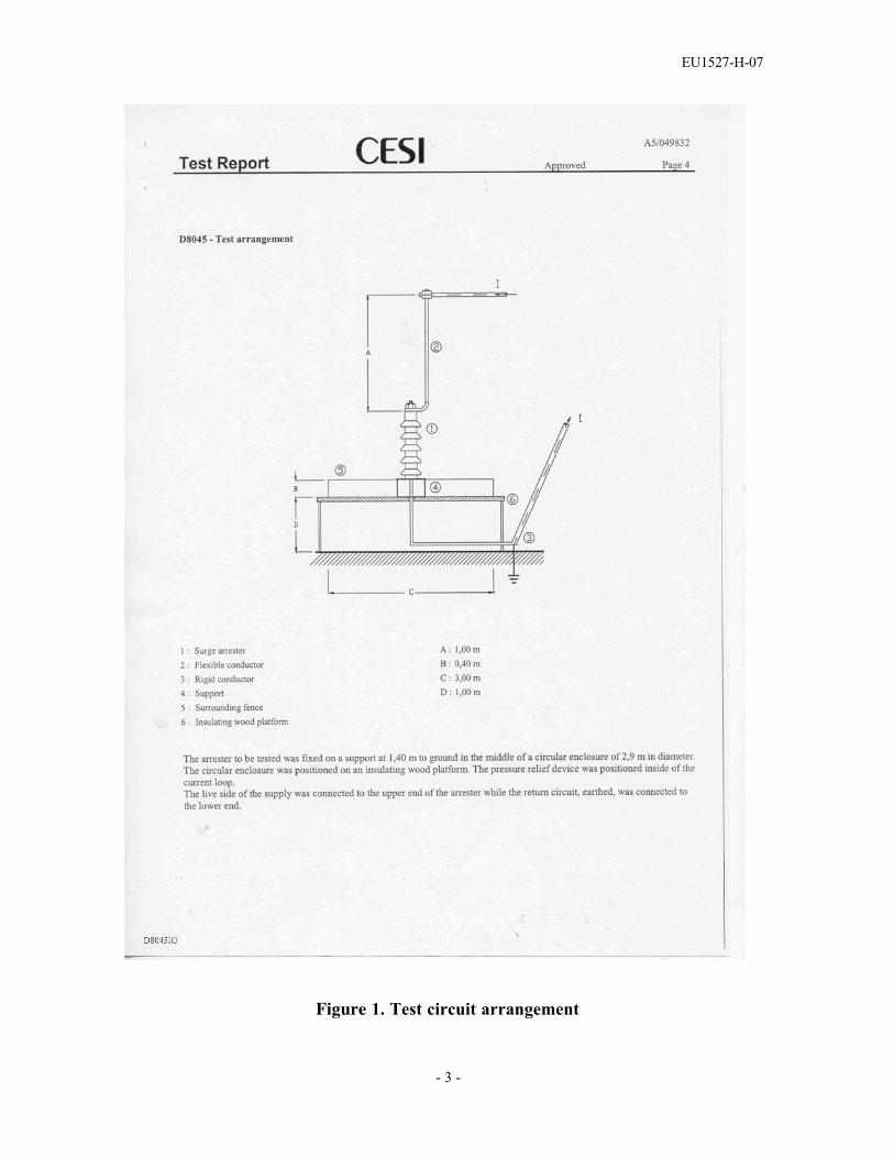
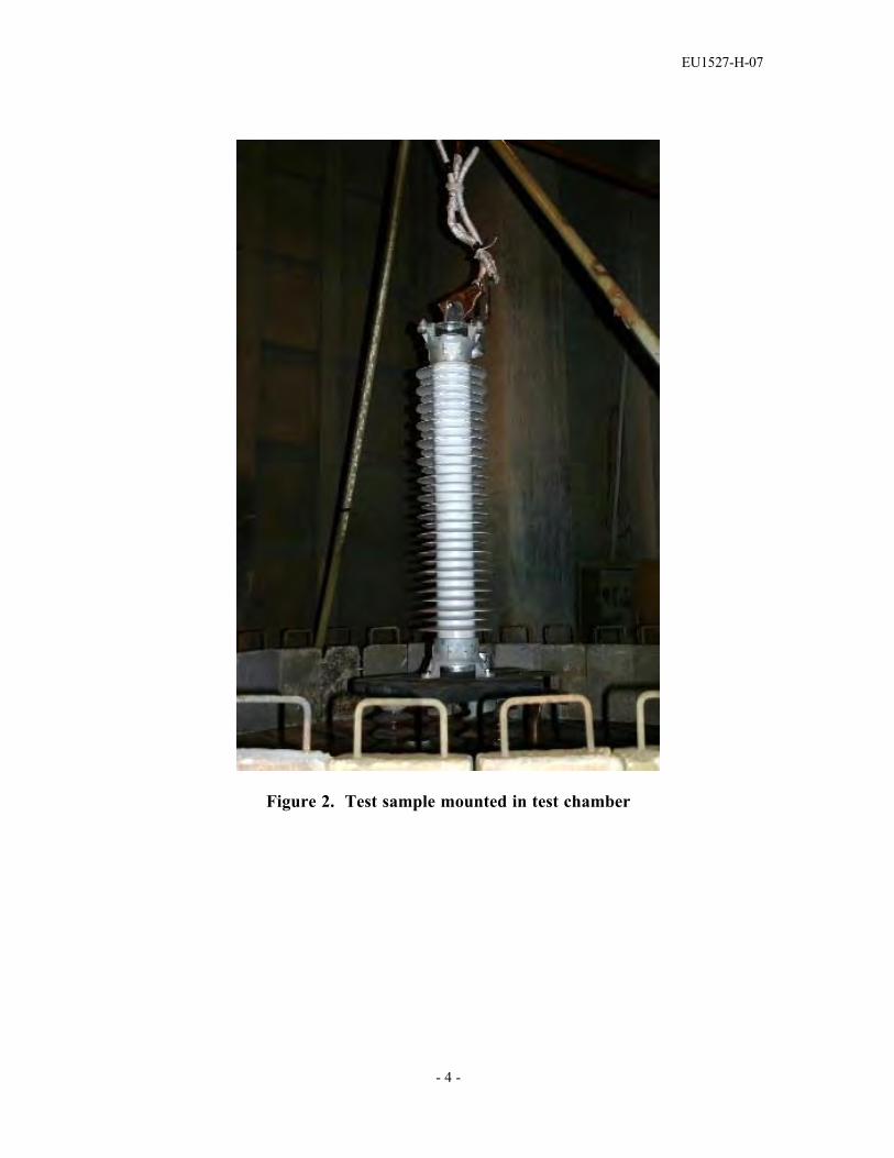
The test samples were of the longest individual unit length used in PH3 and PH4 arresters(1352 mm without terminal cap, 1495 mm with terminal cap). The test samplescontained as many resistor elements as good be assembled into the unit. Figure 1 showsthe general arrangement of the test set up. Figure 2 shows one of the units in the testchamber.
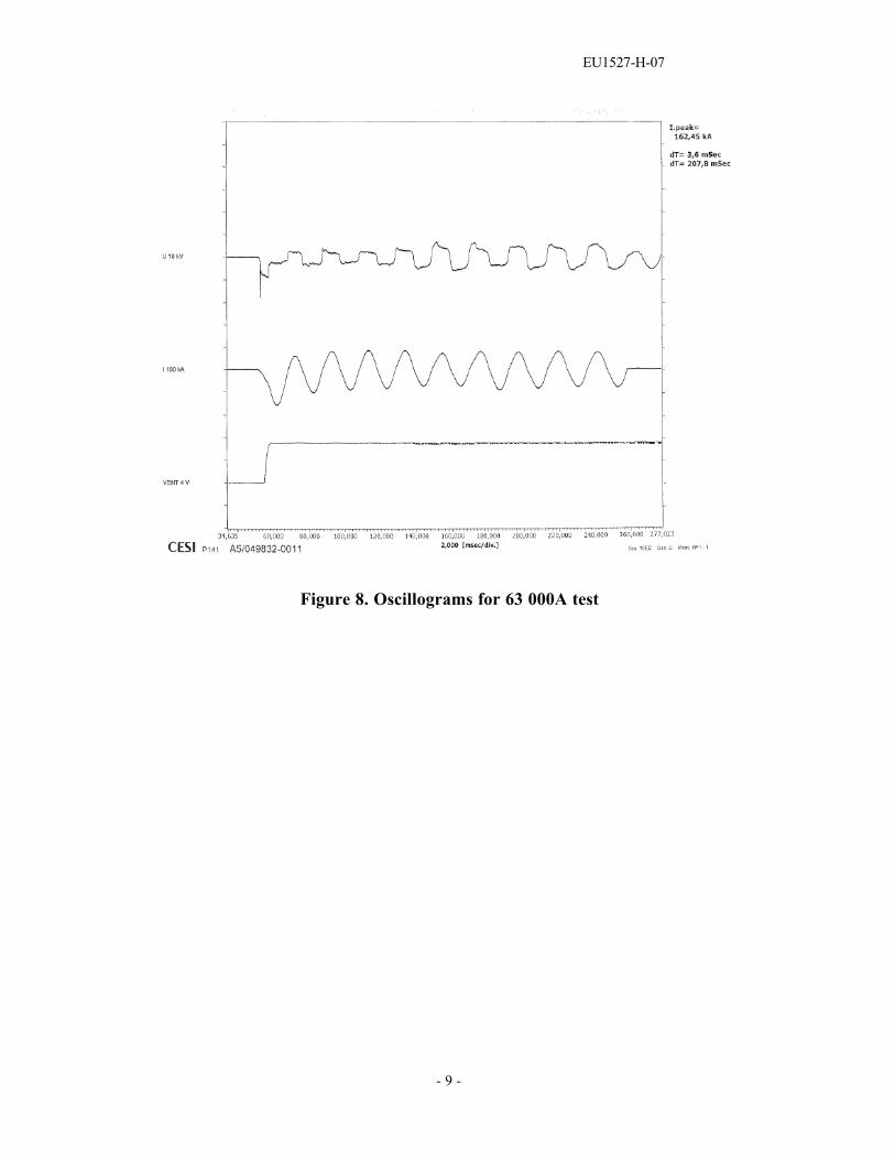
All three samples successfully withstood their respective short circuit current tests withno fracturing of the polymer housing. Actual prospective rms values of test currentswere 14 400 A, 28 000 A and 68 500 A. For the rated current test, the peak of the firsthalf cycle of test current was 162 500 A, meeting the requirement that this be at least 2.5times the rms value of the rated short circuit current. Data sheets for the tests are shownin Figures 3– 5, and associated oscillograms are shown in Figures 6 - 9.
EU1527-H-07
- 3 -
Figure 1. Test circuit arrangement
EU1527-H-07
- 4 -
Figure 2. Test sample mounted in test chamber

EU1527-H-07
- 5 -
Figure 3. Data sheet for 12 000 A test

EU1527-H-07
- 6 -
Figure 4. Data sheet for 25 000 A test

EU1527-H-07
- 7 -
Figure 5. Data sheet for 63 000 A test

EU1527-H-07
- 8 -
Figure 6. Oscillograms for 12 000A test
Figure 7. Oscillograms for 25 000A test
EU1527-H-07
- 9 -
Figure 8. Oscillograms for 63 000A test

EU1527-H-08
IEC Type Test ReportReport No. EU1527-H-08
PH3 Series Polymer-housed Arrester10,000 A Line Discharge Class 3
Internal Partial Discharge
This report records the results of type tests made on PH3 series 10 kA LineDischarge Class 3 arresters, rated up to 420 kV. Tests were performed inaccordance with procedures of IEC Standard 60099-4, Ed. 2.1, 2006, “Surgearresters - Part 4: Metal-oxide surge arresters without gaps for a.c. systems.”
To the best of our knowledge and within the usual limits of testing practice, testsperformed on these arresters demonstrate compliance with the relevant clauses ofthe referenced standard.
M.G. ComberManager, Engineering
Date: 9/29/2006
EU1527-H-08
- 2 -
IEC TYPE TEST REPORTInternal Partial Discharge
Clause 10.8.8 of IEC 60099-4, in reference to Clause 8.8, requires that the longestelectrical unit of the arrester design be subject ed to an internal part ial dischargety pe test . Under the prescribed test ing procedure, the part ial discharge level at1.05 times the cont inuous op erating volt age of the unit shall not exceed 10 pC.
Clause 9.1 c) of this same st andard requires that all manufactured unit s besubject ed to an internal part ial discharge test that is identical to that of Clause 8.8,and that the part ial discharge level of all unit s produced shall not exceed 10 pC.Rout ine test reports are provided on request verifying that this requirement hasbeen met.
By performing the rout ine test ing of unit s according to Clause 9.1 c), the ty pe testrequirements of Clause 8.8 are automat ically met.

EU1527-H-09
IEC Type Test ReportReport No. EU1527-H-09
PH3 Series Polymer-housed Arrester10,000 A Line Discharge Class 3
Bending Moment
This report records the results of type tests made on PH3 series 10 kA LineDischarge Class 3 arresters, rated up to 420 kV. Tests were performed inaccordance with procedures of IEC Standard 60099-4, Ed. 2.1, 2006, “Surgearresters - Part 4: Metal-oxide surge arresters without gaps for a.c. systems.”
To the best of our knowledge and within the usual limits of testing practice, testsperformed on these arresters demonstrate compliance with the relevant clauses ofthe referenced standard.
M.G. ComberManager, Engineering
Date: 9/29/2006

EU1527-H-09
- 2 -
IEC TYPE TEST REPORTBending Moment
TESTS PERFORMED:A bending moment test was performed as described in Clause 10.8.9 of IEC 60099-4, forpolymer-housed arresters with enclosed gas volume and a separate sealing system, on afully assembled arrester unit that had been seal leak tested according to 9.1 d) of thestandard. Prior to the mechanical testing, the unit was subjected to tests to determinewatts loss, partial discharge, and residual voltage.
The test unit was securely mounted to the horizontal base of the test equipment andlateral (horizontal) loading was applied to the free end of the unit, in a directionperpendicular to the axis of the unit, at a rate necessary to reach the bending momentcorresponding to the maximum permissible service load (MPSL) in approximately 50 s.The load was then maintained at not less than this level for about 90 s. Deflection wasmeasured prior to release of the load. After release of load, the test sample was inspectedto verify that no mechanical damage had occurred, and the load-deflection curve wasexamined to verify that there was no discontinuity, and that the strain condition afterrelease of load was within allowed limits.
The sample was then subjected to the complete Moisture Ingress test described in10.8.13 of the standard). At the conclusion of the Moisture Ingress test, the electrical andseal leak tests were repeated to verify that any changes were within allowed limits, and avisual inspection was made to verify that no mechanical damage had occurred.
RESULTS:The PH3 series of arresters uses one, two or three units (depending on voltage rating andoverall creepage distance requirements), with all units using one general polymer housingtype (all housings have the same diameter and weathershed profile, differing only inheight) and only one design of end fitting. The greatest bending stress is always at thebottom end of the bottom unit of the arrester, and according to the requirements of IEC60099-4, it is therefore necessary only to perform a test on one unit.
The tested unit was the longest electrical section used in PH3 arresters, with Ur = 150 kVand Uc = 120 kV. Results of initial tests are shown in Table 1.

EU1527-H-09
- 3 -
Table 1. Results of initial measurements
Test Parameter ResultWatts loss at Uc 13.8 WResidual voltage at 10 kA 8/20 340.4 kVInternal partial discharge at 1.05 x Uc < 10 pCSeal leak < 1x 10⁻⁷ Pa.m3s-1
The MPSL declared for PH3 arresters is 8000 Nm. A loading curve for the bending testis shown in Figure 1. Examination of the loading curve shows no discontinuity during theload application.
Maximum deflection of the top end of the unit during application of MPSL was 57 mm,and after the load was released the residual deflection was zero.
The unit was then subjected to the Moisture Ingress test (see EU1527-H-12 section ofthe PH3 arrester type test report for details and results of this test). At the conclusion ofthe Moisture Ingress test, initial tests conducted on the unit (watts loss, partial discharge,residual voltage and seal leak) were repeated, with results shown in Table 2.
Table 2. Results of final measurements
Test Parameter Result Change frominitial test
Watts loss at Uc 15.0 W + 8.7%Residual voltage at 10 kA 8/20 338.5 kV - 0.6 %Internal partial discharge at 1.05 x Uc < 10 pC --Seal leak < 1x 10⁻⁷ Pa.m3s-1 --
The change in watts loss and residual voltage from the values initially measured were wellwithin the maximum allowed change of 20% and 5%, respectively. Additionally, partialdischarge and seal leak rate were found to be below the allowed limits of 10 pC and 1x 10-
7 Pa.m3s-1, respectively.

EU1527-H-09
- 4 -
Figure 1. Bending moment at bottom end of unitMax design moment at MPSL: 8000 Nm
0
1000
2000
3000
4000
5000
6000
7000
8000
9000
0 50 100 150 200
Time (s)
Ben
ding
Mom
ent
(N.m
)

EU1527-H-10
IEC Type Test ReportReport No. EU1527-H-10
PH3 Series Polymer-housed Arrester10,000 A Line Discharge Class 3
Seal Leak Rate
This report records the results of type tests made on PH3 series 10 kA LineDischarge Class 3 arresters, rated up to 420 kV. Tests were performed inaccordance with procedures of IEC Standard 60099-4, Ed. 2.1, 2006, “Surgearresters - Part 4: Metal-oxide surge arresters without gaps for a.c. systems.”
To the best of our knowledge and within the usual limits of testing practice, testsperformed on these arresters demonstrate compliance with the relevant clauses ofthe referenced standard.
M.G. ComberManager, Engineering
Date: 9/29/2006
EU1527-H-10
- 2 -
IEC TYPE TEST REPORTSeal Leak Rate
Clauses 10.8.11 of IEC 60099-4 requires that one comp let e arrester be subject ed toa seal leak rate test , us ing any sens itive method suit able for the measurement of thesp ecified seal leak test . Us ing the adop ted method, the seal leak rate shall be lowerthan 1x10⁻⁶ Pa.m3s-1.
Clause 9.1 d) of this same st andard requires that , for arrester unit s with sealedhous ing, all manufactured unit s be subject ed to a seal leak test as a rout ine test . Inthis test , the method used for PH3 series arresters is the “vacuum helium masssp ectrometer” method. Wit h this method, the internal air sp ace of the arrester unitis evacuat ed, resulting in a one at mosphere pressure different ial between outs ideand inside, under which conditions the outs ide of the arrester is flooded withhelium. The evacuat ion port is monitored by a mass sp ectrometer tuned to detecthelium, and any helium detected is quantit at ively measured to provide a leak rate.The maximum leak rate accepted for PH3 series arrester unit s is 1x10⁻⁷ Pa.m3s-1,one order of magnitude below the maximum allowed by IEC 60099-4. Rout ine testreports are provided on request verifying that this requirement has been met.
By performing the rout ine test ing of unit s according to Clause 9.1 d), the ty pe testrequirements of Clause 10.8.11 are automat ically met.

EU1527-H-11
IEC Type Test ReportReport No. EU1527-H-11
PH3 Series Porcelain-housed Arrester10,000 A Line Discharge Class 3
Radio Influence Voltage (RIV)
This report records the results of type tests made on PH3 series 10 kA LineDischarge Class 3 arresters, rated up to 420 kV. Tests were performed inaccordance with procedures of IEC Standard 60099-4, Ed. 2.1, 2006, “Surgearresters - Part 4: Metal-oxide surge arresters without gaps for a.c. systems.”
To the best of our knowledge and within the usual limits of testing practice, testsperformed on these arresters demonstrate compliance with the relevant clauses ofthe referenced standard.
M.G. ComberManager, Engineering
Date: 9/29/2006

EU1527-H-11
- 2 -
IEC TYPE TEST REPORTRadio Influence Voltage (RIV)
TESTS PERFO RMED:A fully-assembled arrester, with volt age rating Ur of 312 kV and cont inuousop erating volt age Uc of 249.6 kV, was subject ed to the RIV test as prescribed inClause 10.11 of IEC 60099-4. This samp le represent s an arrester of the longestlength and highest volt age st ress in the PH3 series of arresters . The volt ageap plication was as follows:
• raised to 287 kV (1.15 Uc)• lowered to 262 kV (1.05 Uc)• held at 262 kV for 5 min• lowered in st ep s of ap proximately 0.1 Uc until reaching 0.5 Uc• increased in similar st ep s until reaching 262 kV (1.05 Uc)• held at 262 kV for 5 min• lowered again in st ep s of ap proximately 0.1 Uc until reaching 0.5 Uc
RIV measurements were made at each volt age level. The variable-frequency RIVmeter was tuned to 1 MHz for the measurement s.
RESULTS :Prior to inst alling the arrester in the test circuit , an op en circuit test was run todetermine the background noise of the circuit . The arrester was inst alled and thesequence of volt age ap plications described above was ap plied. Figure 1 shows thearrester inst alled for test . Results of the RIV measurements are shown in Table 1.
At all test volt age levels, the RIV was only marginally above the background noiselevel. IEC 60099-4 allows a maximum RIV level of 2500 µV.

EU1527-H-11
- 3 -
Fi gure 1. 312 kV rate d arrester
Tabl e 1. Me asure d RIV values
Test cond ition Test voltage(k V rms)
RIV(µV)
Open ci rcuit 2-4Arrester ins talled 287 6-20Arrester ins talled 262 (0 min) 4-10Arrester ins talled 262 (5 min) 4-10Arrester ins talled 235 4-10Arrester ins talled 208 2-4Arrester ins talled 181 2-4Arrester ins talled 154 2-4Arrester ins talled 125 2-4Arrester ins talled 154 2-4Arrester ins talled 181 2-4Arrester ins talled 208 4-10Arrester ins talled 235 4-10Arrester ins talled 262 (0 min) 4-10Arrester ins talled 262 (5 min) 4-10Arrester ins talled 235 4-10Arrester ins talled 208 2-10Arrester ins talled 181 2-4Arrester ins talled 154 2-4Arrester ins talled 125 2-4

EU1527-H-12
IEC Type Test ReportReport No. EU1527-H-12
PH3 Series Polymer-housed Arrester10,000 A Line Discharge Class 3
Moisture Ingress
This report records the results of type tests made on PH3 series 10 kA LineDischarge Class 3 arresters, rated up to 420 kV. Tests were performed inaccordance with procedures of IEC Standard 60099-4, Ed. 2.1, 2006, “Surgearresters - Part 4: Metal-oxide surge arresters without gaps for a.c. systems.”
To the best of our knowledge and within the usual limits of testing practice, testsperformed on these arresters demonstrate compliance with the relevant clauses ofthe referenced standard.
M.G. ComberManager, Engineering
Date: 9/29/2006
EU1527-H-12
- 2 -
IEC TYPE TEST REPORTMoisture Ingress
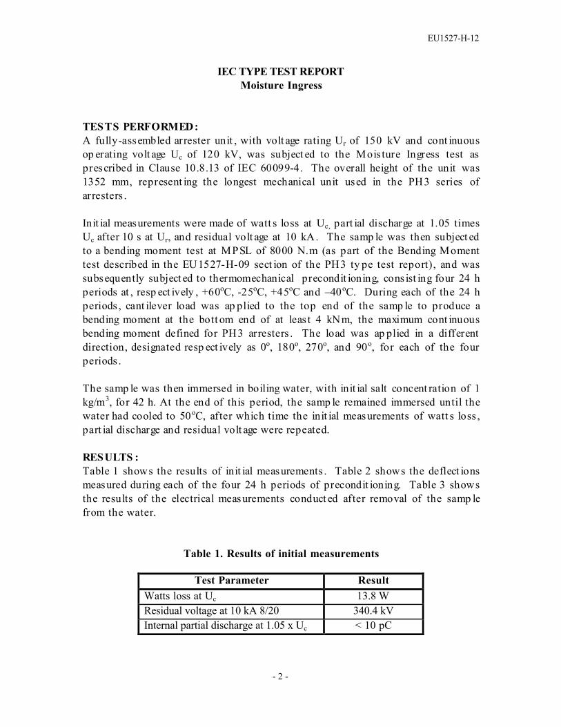
TESTS PERFORMED:A fully-assembled arrester unit , with volt age rating Ur of 150 kV and cont inuousop erating volt age Uc of 120 kV, was subject ed to the Mois ture Ingress test asprescribed in Clause 10.8.13 of IEC 60099-4. The overall height of the unit was1352 mm, represent ing the longest mechanical unit used in the PH3 series ofarresters .
Init ial measurements were made of watt s loss at Uc, part ial discharge at 1.05 timesUc after 10 s at Ur, and residual volt age at 10 kA. The samp le was then subject edto a bending moment test at MPSL of 8000 N.m (as part of the Bending Momenttest described in the EU1527-H-09 sect ion of the PH3 ty pe test report), and wassubsequently subject ed to thermomechanical precondit ioning, cons ist ing four 24 hperiods at , resp ect ively , +60oC, -25oC, +45oC and –40oC. During each of the 24 hperiods , cant ilever load was ap plied to the top end of the samp le to produce abending moment at the bott om end of at leas t 4 kNm, the maximum cont inuousbending moment defined for PH3 arresters . The load was ap plied in a differentdirection, designated resp ect ively as 0o, 180o, 270o, and 90o, for each of the fourperiods .
The samp le was then immersed in boiling water, with init ial salt concent ration of 1kg/m3, for 42 h. At the end of this period, the samp le remained immersed until thewater had cooled to 50oC, after which time the init ial measurements of watt s loss ,part ial discharge and residual volt age were repeated.
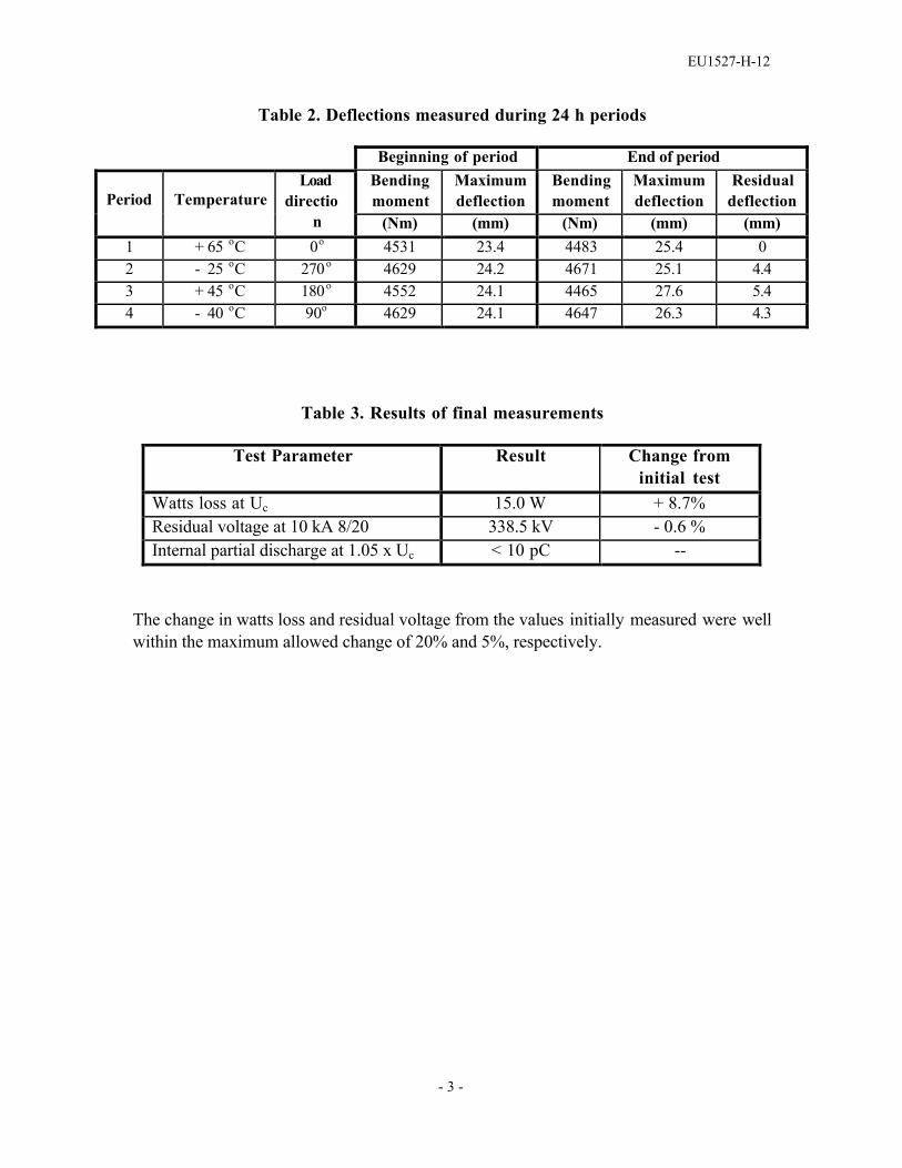
RESULTS :Table 1 shows the results of init ial measurements . Table 2 shows the deflect ionsmeasured during each of the four 24 h periods of precondit ioning. Table 3 showsthe results of the electrical measurements conduct ed after removal of the samp lefrom the water.
Table 1. Results of initial measurements
Test Parameter ResultWatts loss at Uc 13.8 WResidual voltage at 10 kA 8/20 340.4 kVInternal partial discharge at 1.05 x Uc < 10 pC
EU1527-H-12
- 3 -
Table 2. Deflections measured during 24 h periods
Beginning of period End of periodBendingmoment
Maximumdeflection
Bendingmoment
Maximumdeflection
ResidualdeflectionPeriod Temperature
Loaddirectio
n (Nm) (mm) (Nm) (mm) (mm)1 + 65 oC 0o 4531 23.4 4483 25.4 02 - 25 oC 270o 4629 24.2 4671 25.1 4.43 + 45 oC 180o 4552 24.1 4465 27.6 5.44 - 40 oC 90o 4629 24.1 4647 26.3 4.3
Table 3. Results of final measurements
Test Parameter Result Change frominitial test
Watts loss at Uc 15.0 W + 8.7%Residual voltage at 10 kA 8/20 338.5 kV - 0.6 %Internal partial discharge at 1.05 x Uc < 10 pC --
The change in watts loss and residual voltage from the values initially measured were wellwithin the maximum allowed change of 20% and 5%, respectively.

EU1527-H-13
IEC Type Test ReportReport No. EU1527-H-13
PH3 Series Polymer-housed Arrester10,000 A Line Discharge Class 3
Weather Ageing
This report records the results of type tests made on PH3 series 10 kA LineDischarge Class 3 arresters, rated up to 420 kV. Tests were performed inaccordance with procedures of IEC Standard 60099-4, Ed. 2.1, 2006, “Surgearresters - Part 4: Metal-oxide surge arresters without gaps for a.c. systems.”
To the best of our knowledge and within the usual limits of testing practice, testsperformed on these arresters demonstrate compliance with the relevant clauses ofthe referenced standard.
M.G. ComberManager, Engineering
Date: 9/29/2006

EU1527-H-13
- 2 -
IEC TYPE TEST REPORTWeather Ageing
TESTS PERFORMED:A fully-assembled arrest er unit , with volt age rating Ur of 144 kV and cont inuousop erating volt age Uc of 115.2 kV, was subject ed to the Weat her Ageing test seriesA (1000 h salt fog) as prescribed in Clause 10.8.14 of IEC 60099-4. The test wasperformed at the CESI high volt age laborat ory in Milan, It aly.
Init ial measurements were made of reference volt age, at reference current of 17mA pk, and internal part ial discharge at 1.05 times Uc after 10 s at Ur.
The test samp le, was energiz ed at Uc = 115.2 kVrms for a total of 1000 h in the testroom filled with salt fog having the following charact erist ics:
• Salinit y of water solution: 10 kg/m3
• Water flow rate: 0.4 ± 0.1 l/h*m3
The salt fog was not directly sp ay ed on the test samp le. A schemat ic of the testarrangement is shown in Figure 1 (t wo ot her arrester unit s were test ed at the sametime).
Fi gure 1. Test chambe r layout
Visual observations of the condition of the silicone rubber hous ing were made after500 h and at 1000 h. Measurements of reference volt age and internal part ialdischarge were repeated at the conclus ion of the 1000 h test period.
EU1527-H-13
- 3 -
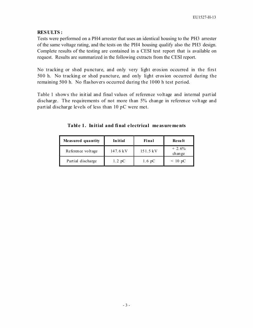
RESULTS :Tests were performed on a PH4 arrester that uses an identical housing to the PH3 arresterof the same voltage rating, and the tests on the PH4 housing qualify also the PH3 design.Complete results of the testing are contained in a CESI test report that is available onrequest. Results are summarized in the following extracts from the CESI report.
No tracking or shed puncture, and only very light eros ion occurred in the firs t 500 h. No tracking or shed puncture, and only light eros ion occurred during theremaining 500 h. No flashovers occurred during the 1000 h test period.
Table 1 shows the init ial and final values of reference volt age and internal part ialdischarge. The requirements of not more than 5% change in reference volt age andpart ial discharge levels of less than 10 pC were met.
Tabl e 1. In itial and fi nal e lectrical me asure me nts
Measured quantity In itial Final Resu lt
Reference volt age 147. 6 kV 151. 5 kV + 2. 6%change
Part ial discharge 1. 2 pC 1. 6 pC < 10 pC
EU1527-H-14.1
IEC Type Test ReportReport No. EU1527-H-14.1
PH3 Series Polymer-housed Arrester10,000 A Line Discharge Class 3
Power Frequency Voltage Versus Time
This report records the results of type tests made on PH3 series 10 kA LineDischarge Class 3 arresters, rated up to 420 kV. Tests were performed inaccordance with procedures of IEC Standard 60099-4, Ed. 2.1, 2006, “Surgearresters - Part 4: Metal-oxide surge arresters without gaps for a.c. systems.”
To the best of our knowledge and within the usual limits of testing practice, testsperformed on these arresters demonstrate compliance with the relevant clauses ofthe referenced standard.
M.G. ComberManager, Engineering
Date: 8/24/2007

EU1527-H-14.1
- 2 -
IEC TYPE TEST REPORTPower Frequency Voltage Versus Time
TESTS PERFORMED:Power frequency voltage versus time tests were performed on a prorated test sectionprepared based on the results of the tests to verify heat dissipation behavior of testsample. Each section consisted of two resistors in series. The resistors were selected torepresent the lowest acceptable reference voltage level. The tests were conducted inaccordance with Annex D of IEC 60099-4.
Prior to the test, measurements were made on the test section to determine its switchingimpulse residual voltage and its reference voltage.
Tests were made for three different time durations (1.1 s, 10 s and 210 s) of elevatedvoltage application. For each test, the section was placed in an oven and heatedovernight to 60 ± 3 °C. After removal from the oven, the section was subjected to twolong duration current impulses, with time between impulses being between 50 and 60seconds. The parameters of the transmission line used to generate these impulsesconformed to the requirements for Line Discharge Class 3 in Table 5 of Clause 8.4.2 ofIEC 60099-4. Within 100 milliseconds of the second long duration current impulse, anelevated power frequency voltage (above Uc) was applied for a measured period of time,following which the voltage was reduced to the adjusted value Uc for 30 min. During the30 min period at Uc the power dissipation was monitored to verify thermal stability.
Table 1 lists the parameters of the test sections and the corresponding transmission lineparameters used for the test. Uc for the PH3 series of arresters has been established as0.795 times the lowest acceptable reference voltage in routine tests, and Ur has beenestablished as 1.25 times Uc . This is represented in this type test by assigning the testsample Uc equal to 0.795 x Uref of the test sample, and test sample Ur at 1.25 times thisvalue . The minimum energy required for each line discharge for Class 3 arresters isdetermined from the following formula given in Clause 8.4.2 of IEC 60099-4
W = Ures x (UL – Ures) x 1/Z x T
where Ures is the switching impulse residual voltage at 250 A.

EU1527-H-14.1
- 3 -
Table 1. Test section and transmission line parametersParameter Value
Switching impulse residual voltage (kV) Ures ReferenceCurrent (mA) IrefReference Voltage (kVc / √2) VrefCOV ( kV rms) UcRating (kV rms) UrArrester Classification (kA)Line Discharge ClassVirtual Duration of Peak (µs, 90-90%) T - minimumSurge Impedance (Ω) Z - max (1.3 Ur)Charging Voltage (kV) UL – min (2.8 Ur)Energy required (kJ) - min
20.629.5
11.509.1511.44
103
240014.8732.0338.0
RESULTS:A short circuit test was performed on the generator to confirm that generator impedanceand duration of the current discharge met the requirements listed in Table 1. Theoscillogram of Figure 1 shows
Zg = 9 117 V / 614.7 A = 14.831 Ω Virtual Duration of Peak = 2 423 µs
Figure 1. Oscillogram of discharge current for generator short circuit set up test

EU1527-H-14.1
- 4 -
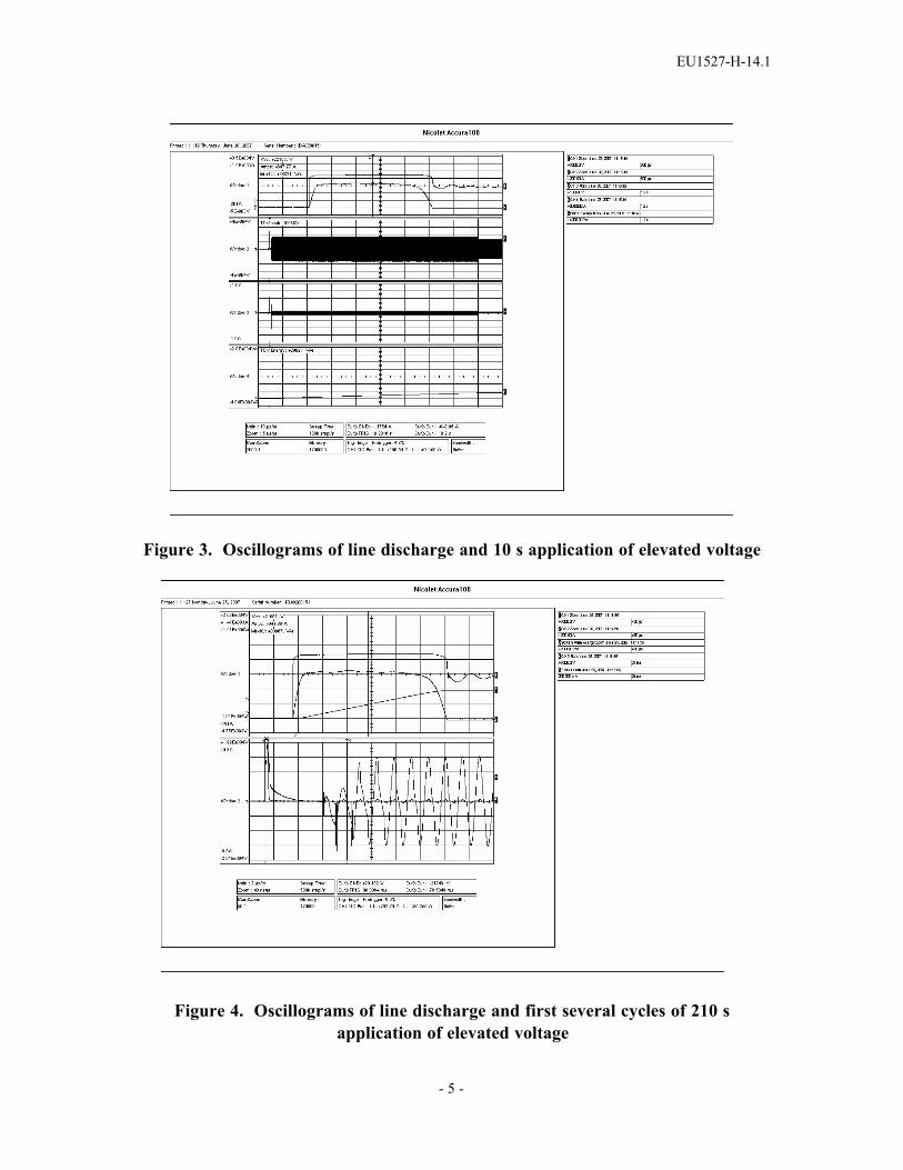
Table 2 lists measurements made during the application of the line discharges for the threetests. Oscillograms made during this portion of the test are shown in Figures 2 – 4.Tables 3 and 4, respectively, list measurements made during the application of elevatedvoltage and during the subsequent 30 min application of Uc.
Figure 5 shows the three test points (elevated voltages for 1.1 s, 10 s and 210 s)superimposed on the characteristic of power frequency voltage vs. time for PH3 series ofarresters.
Table 2. Line discharge measurements
Sample for 1.1 s test Sample for 10 s test Sample for 210 s testDischargeparameters 1st
discharge2nd
discharge1st
discharge2nd
discharge1st
discharge2nd
dischargeCurrent (A) 623 650 667 648 666 642
Voltage (kV) 21.1 22.1 21.9 22.2 21.7 22.0Energy (kJ) 38.3 38.8 39.5 38.8 38.9 38.1
Figure 2. Oscillograms of line discharge and 1.1 s application of elevated voltage
EU1527-H-14.1
- 5 -
Figure 3. Oscillograms of line discharge and 10 s application of elevated voltage
Figure 4. Oscillograms of line discharge and first several cycles of 210 sapplication of elevated voltage

EU1527-H-14.1
- 6 -
Table 3. Measurements of voltage and current during application of elevatedvoltage
1.1 s elevated voltage 10 s elevated voltage 210 s elevated voltage
Elapsedtime Applied voltage Current
Elapsedtime Applied voltage Current
Elapsedtime Applied voltage Current
s kVrms pu Ur mA peak s kVpeak pu Ur mA peak s kVrms pu Ur mA peak
0.07 12.84 1.116 3.13 0.07 11.63 1.011 101.7 0 10.91 0.948 36.90.21 12.84 1.116 3.15 1.06 11.74 1.021 109.2 13 10.94 0.952 32.70.31 12.87 1.119 3.18 2.04 11.76 1.022 106.7 39 10.95 0.952 32.20.40 12.89 1.121 3.25 3.00 11.77 1.024 110.8 50 10.94 0.952 32.50.51 12.90 1.122 3.25 4.03 11.76 1.022 105.8 64 10.91 0.949 32.80.61 12.90 1.122 3.24 5.06 11.76 1.023 108.3 70 10.92 0.949 32.60.70 12.88 1.120 3.26 6.02 11.76 1.022 105.8 89 10.93 0.950 32.20.81 12.92 1.123 3.31 7.03 11.76 1.023 106.7 101 10.94 0.952 33.60.90 12.91 1.122 3.37 8.11 11.76 1.022 109.2 120 10.98 0.955 35.01.00 12.89 1.121 3.35 9.24 11.77 1.024 112.1 210 10.96 0.953 39.21.20 12.89 1.121 3.41 10.20 11.77 1.024 112.1Avgrms
voltageduringperiod
12.88 1.120
Avgrms
voltageduringperiod
11.75 1.022
Avgrms
voltageduringperiod
10.94 0.951
Table 4. Measurements of power dissipation and current during 30 min at Uc
1.1 s elevated voltage 10 s elevated voltage 210 s elevated voltage
Elapsedtime
Appliedvoltage
Powerdiss. Current
Elapsedtime
Appliedvoltage
Powerdiss. Current
Elapsedtime
Appliedvoltage
Powerdiss Current
mm:ss kVrms W mApeak mm:ss kVrms W mA
peak mm:ss kVrms W mApeak
00:00 9.26 35.02 9.52 00:00 9.27 18.58 5.15 00:00 9.26 27.96 8.1400:30 9.20 27.83 7.54 00:30 9.23 16.30 4.69 00:30 9.18 25.62 7.3501:00 9.17 25.25 7.24 01:00 9.24 15.62 4.44 01:00 9.17 24.56 6.7602:00 9.19 23.06 6.42 02:00 9.21 14.22 4.09 02:00 9.16 23.04 6.3005:00 9.19 18.82 5.41 05:00 9.18 11.87 3.48 05:00 9.22 20.72 5.9210:00 9.17 15.03 4.29 10:00 9.21 9.93 3.06 10:00 9.18 16.64 4.8020:00 9.19 11.16 3.30 20:00 9.17 7.38 2.43 20:00 9.16 12.13 3.5730:00 9.22 9.04 2.77 30:00 9.18 5.97 2.07 30:00 9.22 9.84 2.92

EU1527-H-14.1
- 7 -
0.9
0.95
1
1.05
1.1
1.15
1.2
0.1 1 10 100 1000Time - s
Volta
ge -
per
unit
of U
r
Figure 5. Power frequency voltage vs. time characterstic for PH3 series arresters,with test points for 1.1 s, 10 s and 210 s