IEC template iecstd.dot - Home - CIMugcimug.ucaiug.org/Projects/CIM-OpenADR/Shared...
535
publication no./stage( CDV,FDIS... ) IEC:201X – 1 – 1 1 2
Transcript of IEC template iecstd.dot - Home - CIMugcimug.ucaiug.org/Projects/CIM-OpenADR/Shared...

publication no./stage(CDV,FDIS...) IEC:201X – 1 –1
1
2

– 2 – publication no./stage(CDV,FDIS...) IEC:201X
CONTENTS
FOREWORD ......................................................................................................................................... 5
INTRODUCTION .................................................................................................................................. 9
Scope .................................................................................................................................................. 12
Requirements ..................................................................................................................................... 14
2.1 Common architecture model - architectural requirements .....................................14 2.2 Communication requirements for the Smart Grid and the Smart Grid
Connection Point (interface into the premises) .......................................................20 2.3 Common messages – information to be exchanged ...............................................21
2.3.1 Intention of User Stories and Use Cases .............................................21 2.3.2 Relationship of User Stories and Use Cases .......................................22 2.3.3 Requirements for d ata exchanged ........................................................24 2.3.4 Definition of specific application concepts ...........................................31 2.3.5 Mapping use cases with data model requirements ..............................35 2.3.6 Example of a complete process cycle ...................................................37
Annex .................................................................................................................................................. 50
A.1 References ..................................................................................................................50 A.2 User stories .................................................................................................................51
A.2.1 The user wants to get the laundry done by 8:00pm ............................52 A.2.2 The user wants to have his Electro Vehicle charged by
8:00am ......................................................................................................53 A.2.3 The grid recognizes (severe) stability issues .......................................54 A.2.4 Limitation to fixed amount of power power - The user wants to
limit his consumption to his own local production (e.g. PV) ...............55 2.3.7 CEM manages Simple Devices ..............................................................55 A.2.5 The Customer wants to sell his flexibility to the grid ...........................56 A.2.6 The Customer wants to sell own decentralized energy (e.g.
PV) to Smart Grid ....................................................................................57 A.2.7 Grid related Emergency Situations (Blackout prevention) ..................57 A.2.8 The customer wants to connect a new smart device to the
CEM ..........................................................................................................57 A.2.9 A smart device disconnects unexpectedly (failure) .............................58 A.2.10 The consumer wants to be informed on their historic and
forecasted energy use ............................................................................58 A.2.11 The consumer wants to know an estimate of the yearly energy
cost of a smart device ............................................................................58 A.2.12 The consumer wants a storage device to feed energy to the
grid once the tariff reaches a certain threshold ...................................58 A.2.13 Manage energy consumption of smart devices by Smart Grid ...........59A.2.14 Manage in-premises Battery System ....................................................60 A.2.15 Manage Distributed Energy Resources (DER) .....................................60 A.2.16 Peak Shift Contribution by Battery Aggregation ..................................61 A.2.17 Control of Smart home appliances based on price information
by time slot ...............................................................................................61 A.2.18 Control of Smart home appliances in response to power
saving request from Electric power supplier ........................................62 A.2.19 Control of Smart home appliance before power cut ............................62 A.2.20 Control of Smart home Appliances in case of natural disaster ..........63
2
34
5
6
7
8
9
1011121314151617181920
2122232425262728293031323334353637383940414243444546474849505152

publication no./stage(CDV,FDIS...) IEC:201X – 3 –
A.2.21 Bilateral Demand Response (Negawatt Transaction= Japanese related requirement) ..............................................................64
A.3 Use Case mapping (User Stories – Use Cases) .....................................................65 A.4 Use Case descriptions ...............................................................................................66
A.4.1 Introduction ..............................................................................................66 A.4.2 JWG1100-HLUC Flexible start of a Smart Device (SD) ......................67 A.4.3 SPECIFIC USE CASE (JWG1101) SD informs CEM about
flexible start ..............................................................................................76 A.4.4 SPECIFIC USE CASE (JWG-SPUC1.2) CEM informs SD
about starting time ...................................................................................82 A.4.5 SPECIFIC USE CASE (JWG1103) CEM informs SD about slot
shift ...........................................................................................................88 A.4.6 HIGH LEVEL USE CASE (JWG 1110 ) Temperature Control of
Smart appliances based on price information ......................................94 Con tr ol of Smart home appliances based on price information by time slot ........94A.4.7 HIGH LEVEL USE CASE (JWG 1110 ) Fuel Cell Operation with
Fixed Tariff Profile .................................................................................102 A.4.8 HIGH LEVEL USE CASE (JWG 1111 ) Fuel Cell Operation with
Fixed Tariff Profile .................................................................................110 A.4.9 JWG1200-HLUC Flexible start of a Smart Device (SD) ....................118 A.4.10 JWG2000-HLUC Demand-supply Adjustment of Cooperation
between Supplier and Customer .........................................................127 A.4.11 HIGH LEVEL USE CASE (JWG 2001 ) “ Building Energy
Management ( Model 2 ) ” ...................................................................136 A.4.12 HIGH LEVEL USE CASE (JWG 2002 ) “ Energy Management of
Groups of Building in the District ( Model 3 ) ” ..................................143 A.4.13 HIGH LEVEL USE CASE (JWG 2010 ) Acceleration of
producing power by REs .......................................................................152 A.4.14 High Level Use Case Adjustment of energy production &
consumption in normal conditions .......................................................160 A.4.15 HIGH LEVEL USE CASE (JWG 2012 ) Energy accommodation
in disaster conditions ............................................................................169 FOREWORD ......................................................................................................................................... 7
INTRODUCTION ................................................................................................................................ 11
Scope .................................................................................................................................................. 14
Relevant applications ........................................................................................................................16
2.1 Energy Management ..................................................................................................16 2.1.1 Traffic light concept .................................................................................16 2.1.2 Flexibility (Demand Response) ..............................................................17 2.1.3 Direct load / generation management (Demand Side
Management) ...........................................................................................18 2.2 Comfort ........................................................................................................................18 2.3 Upcoming applications ...............................................................................................19
Architectural requirements ................................................................................................................20
Communication requirements for the Smart Grid and the Smart Grid Connection Point (interface into the premises) .....................................................................................................25
Intention of User Stories and Use Cases ........................................................................................26
5.1 Relationship of User Stories and Use Cases ..........................................................27 5.2 Example of a complete process cycle ......................................................................28 5.3 User Stories ................................................................................................................. 35
5.3.1 The user wants to get the laundry done by 8:00pm ............................36
4
535455565758596061626364656667686970717273747576777879808182838485
86
87
88
8990919293949596
9798
99
100101102103

– 4 – publication no./stage(CDV,FDIS...) IEC:201X
5.3.2 The user wants to have his Electro Vehicle charged by 8:00am ......................................................................................................37
5.3.3 The grid recognizes (severe) stability issues .......................................38 5.3.4 Limitation to fixed amount of power ......................................................39 5.3.5 CEM manages Simple Devices ..............................................................39 5.3.6 The Customer wants to sell his flexibility to the grid ...........................40 5.3.7 The Customer wants to sell own decentralized energy (e.g.
PV) to Smart Grid ....................................................................................41 5.3.8 Grid related Emergency Situations (Blackout prevention) ..................41 5.3.9 The customer wants to connect a new smart device to the
CEM ..........................................................................................................42 5.3.10 A smart device disconnects unexpectedly (failure) .............................42 5.3.11 The consumer wants to be informed on their historic and
forecasted energy use ............................................................................42 5.3.12 The consumer wants to know an estimate of the yearly energy
cost of a smart device ............................................................................42 5.3.13 The consumer wants a storage device to feed energy to the
grid once the tariff reaches a certain threshold ...................................43 5.3.14 Manage energy consumption of smart devices by Smart Grid ...........435.3.15 Manage in-premises Battery System ....................................................44 5.3.16 Manage Distributed Energy Resources (DER) .....................................44 5.3.17 Peak Shift Contribution by Battery Aggregation ..................................45 5.3.18 Control of Smart home appliances based on price information
by time slot ...............................................................................................45 5.3.19 Control of Smart home appliances in response to power
saving request from Electric power supplier ........................................46 5.3.20 Control of Smart home appliance before power cut ............................46 5.3.21 Control of Smart home Appliances in case of natural disaster ..........475.3.22 Bilateral Demand Response (Negawatt Transaction=
Japanese related requirement) ..............................................................48 Use Case mapping (User Stories – Use Cases) ............................................................................49
Use Cases .......................................................................................................................................... 50
7.1 Introduction ..................................................................................................................50 7.2 Actor list .......................................................................................................................51 7.3 Energy related use cases ..........................................................................................54
7.3.1 Energy forecast, price & environmental information (WGSP 2110) .........................................................................................................54
7.3.2 Flexible start of a Smart Device (SD) - (JWG-UC1) ............................61 7.3.3 Time synchronization ..............................................................................63 7.3.4 Direct load / generation management (WGSP 2120) ..........................64
7.4 Management & Monitoring .........................................................................................68 7.4.1 Simple Smart Device management .......................................................68 7.4.2 Smart Device Program Status request / notification ...........................68 7.4.3 Smart Device status request / alert / notification .................................69
7.5 Registration .................................................................................................................69 7.6 Deregistration ..............................................................................................................69
Mapping use cases – data model requirements .............................................................................71
8.1 XXXXXXXXX ...............................................................................................................71 Mapping of the use cases with messages .......................................................................................73
9.1 Energy related data model requirements .................................................................73
5
104105106107108109110111112113114115116117118119120121122123124125126127128129130131132133134
135
136137138139140141142143144145146147148149150
151152
153

publication no./stage(CDV,FDIS...) IEC:201X – 5 –
9.1.1 Energy forecast, price & environmental information ...........................73 9.1.2 Flexible start of a Smart Device (SD) - (JWG-UC1) ............................77 9.1.3 Direct load / generation management ...................................................78
9.2 Management & Monitoring .........................................................................................78 9.2.1 Simple Smart Device management .......................................................78 9.2.2 CEM Smart Device Program Status request / notification .........799.2.3 CEM Smart Device Information request / Alerts /
Notifications .............................................................................................79 9.3 Registration .................................................................................................................79 9.4 Deregistration ..............................................................................................................79
Messages & XSD structure ...............................................................................................................80
10.1 powerSequenceDescriptionListData .........................................................................80 10.2 powerSequenceStateListData ...................................................................................81 10.3 powerSequenceScheduleConstraintsListData ........................................................82 10.4 powerTimeSlotScheduleListData ..............................................................................83 10.5 powerTimeSlotValueListData ....................................................................................84 10.6 powerTimeSlotScheduleConstraintsListData ..........................................................85 10.7 meteringValueListData ...............................................................................................86 10.8 meteringUnitData ........................................................................................................86 10.9 meteringObisValueListData .......................................................................................87 10.10 meteringObisUnitListData ..........................................................................................87 10.11 commodityListData .....................................................................................................88 10.12 commodityIncentiveIdListData ..................................................................................89 10.13 commodityTierScheduleListData ..............................................................................90 10.14 priceTierListData .........................................................................................................91 10.15 priceListData ...............................................................................................................91 10.16 benchmarkDescriptionListData .................................................................................93 10.17 benchmarkListData .....................................................................................................94 10.18 priceDataCapabilities (check whether “notify” says “in” and/or read says
“out”) ............................................................................................................................. 95 10.19 powerSequenceScheduleConfigurationRequestCall ..............................................96 10.20 powerSequenceScheduleConfigurationListData .....................................................96 10.21 powerTimeSlotScheduleConfigurationListData (in case a slot shift is
involved) ......................................................................................................................97 10.22 powerTimeSlotScheduleConfigurationListData .......................................................98 10.23 timeInformationData ...................................................................................................99 10.24 timeDistributorData .....................................................................................................99 10.25 timePrecisionData .......................................................................................................99 10.26 To be added ..............................................................................................................100 10.27 To be added ..............................................................................................................100
Annex ................................................................................................................................................ 101
A.1 References ................................................................................................................101 A.2 Use Case descriptions .............................................................................................102
A.2.1 HIGH LEVEL USE CASE (WGSP211x) Exchanging information on consumption, price and warnings with external actors and within the home ..................................................................102
Description of the Use Case ...........................................................................................................102
Name of Use Case ........................................................................................................................... 102
Version Management .......................................................................................................................102
7
154155156157158159160161162163164
165166167168169170171172173174175176177178179180181182183184185186187188189190191192193194
195196197198199200
201
202

– 6 – publication no./stage(CDV,FDIS...) IEC:201X
Scope and Objectives of Use Case ...............................................................................................102
Narrative of Use Case .....................................................................................................................104
General Remarks ............................................................................................................................. 106
Diagrams of Use Case .................................................................................................................... 106
Technical Details ............................................................................................................................. 106
Actors: People, Systems, Applications, Databases, the Power System, and Other Stakeholders ............................................................................................................................ 106
Preconditions, Assumptions, Post condition, Events ...................................................................109
References / Issues .........................................................................................................................110
Further Information to the Use Case for Classification / Mapping .............................................110
Step by Step Analysis of Use Case ...............................................................................................111
WGSP 2111: Use case scenario 1: Information regarding power consumption / generation / storage of individual smart devices .................................................................111
Diagram of use case ........................................................................................................................ 111
Steps – Normal ................................................................................................................................ 112
WGSP 2111: Use case scenario 2: Information regarding total power consumption or generation ................................................................................................................................. 113
Diagram of use case ........................................................................................................................ 113
Steps – Normal ................................................................................................................................ 114
WGSP 2112: Price and environmental information ......................................................................115
Diagram of use case ........................................................................................................................ 115
Steps – Normal ................................................................................................................................ 115
WGSP 2113: use case scenario 1: Warning signals from Smart devices .................................116
Diagram of use case ........................................................................................................................ 117
Steps – Normal ................................................................................................................................ 117
WGSP 2113: use case scenario 2: Warning signals from the CEM ...........................................118
Diagram of use case ........................................................................................................................ 118
Steps – Normal ................................................................................................................................ 119
WGSP 2114: Retrieve status of smart devices ............................................................................120
Diagram of use case ........................................................................................................................ 120
Steps – Normal ................................................................................................................................ 120
Steps – Alternative, Error Management, and/or Maintenance/Backup Scenario .....................121
Information Exchanged ................................................................................................................... 122
Common Terms and Definitions .....................................................................................................122
Notes and open issues .................................................................................................................... 122
A.2.2 HIGH LEVEL USE CASE (JWG-HLUC1.1) Flexible start of a Smart Device (SD) ................................................................................123
Description of the Use Case ...........................................................................................................123
Name of Use Case ........................................................................................................................... 123
Diagrams of Use Case .................................................................................................................... 125
Technical Details ............................................................................................................................. 126
Step by Step Analysis of Use Case ...............................................................................................129
Information Exchanged ................................................................................................................... 130
Requirements (optional) .................................................................................................................. 130
8
203
204
205
206
207
208209
210
211
212
213
214215
216
217
218219
220
221
222
223
224
225
226
227
228
229
230
231
232
233
234
235
236
237
238239240
241
242
243
244
245
246
publication no./stage(CDV,FDIS...) IEC:201X – 7 –
Common Terms and Definitions .....................................................................................................131
Custom Information (optional) ........................................................................................................131
A.2.3 SPECIFIC USE CASE (JWG-SPUC1.1) SD informs CEM about flexible start .................................................................................132
Description of the Use Case ...........................................................................................................132
Diagrams of Use Case .................................................................................................................... 133
Technical Details ............................................................................................................................. 134
Step by Step Analysis of Use Case ...............................................................................................136
Steps – Scenario Name .................................................................................................................. 136
Steps – Scenarios ............................................................................................................................ 136
Information Exchanged ................................................................................................................... 137
Common Terms and Definitions .....................................................................................................137
A.2.4 SPECIFIC USE CASE (JWG-SPUC1.2) CEM informs SD about starting time ................................................................................138
Description of the Use Case ...........................................................................................................138
Diagrams of Use Case .................................................................................................................... 139
Technical Details ............................................................................................................................. 140
A.2.5 SPECIFIC USE CASE (JWG-SPUC1.1) CEM informs SD about slot shift .......................................................................................144
A.2.6 HIGH LEVEL USE CASE (WGSP2120) Direct load / generation management .......................................................................145
Description of the Use Case ...........................................................................................................145
Diagrams of Use Case .................................................................................................................... 148
Technical Details ............................................................................................................................. 148
Step by Step Analysis of Use Case ...............................................................................................153
Information Exchanged ................................................................................................................... 161
Common Terms and Definitions .....................................................................................................161
Notes and open issues .................................................................................................................... 161
A.2.7 HIGH LEVEL USE CASE (WGSP2140) Tariff synchronization ......163Description of the Use Case ...........................................................................................................163
Diagrams of Use Case .................................................................................................................... 165
Technical Details ............................................................................................................................. 166
Step by Step Analysis of Use Case ...............................................................................................170
Information Exchanged ................................................................................................................... 175
Common Terms and Definitions .....................................................................................................175
Notes and open issues .................................................................................................................... 175
A.2.8 Management & Monitoring ...................................................................176 A.2.9 Registration ............................................................................................177 A.2.10 Deregistration ........................................................................................177
Figure 1 – Examples of demand response capabilities [1] ...........................................................11
Figure 2 – Smart Environment as of today .....................................................................................12
Figure 3 – Requirements for Interoperability ..................................................................................13
Figure 7 – Flexibility Functional Architecture (Smart Grid Coordination Group Sustainable Process (EU M490)) .....................................................................................................14
10
247
248
249250251
252
253
254
255
256
257
258
259260261
262
263
264265266267268
269
270
271
272
273
274
275276
277
278
279
280
281
282
283284285286
287
288
289
290291

– 8 – publication no./stage(CDV,FDIS...) IEC:201X
Figure 8 – Interfaces of Flexibility Functional Architecture ...........................................................15
Figure 9 – Neutral interfaces ............................................................................................................16
Figure 10 – Mapping I/F structure ....................................................................................................16
Figure 11 – Mapping of messages ...................................................................................................17
Figure 12 – Different CEM configurarions .......................................................................................17
Figure 13 – Physical combinations ..................................................................................................18
Figure 14 – Cascaded CEM architecture ........................................................................................18
Figure 15 – User Stories & Use Cases process .............................................................................22
Figure 16 – Relationship User Stories and Uas Cases .................................................................23
Figure 4 – Traffic Light Concept [3] .................................................................................................31
Figure 5 – Structure of a power profile ............................................................................................33
Figure 6 – Structure of an easy power profile ................................................................................33
Figure 17 – Structure of a price profile ............................................................................................34
Figure 17 – Collection of User Stories ............................................................................................50
Figure 1 – Examples of demand response capabilities .................................................................13
Figure 2 – Smart Environment as of today .....................................................................................14
Figure 3 – Requirements for Interoperability ..................................................................................15
Figure 4 – Traffic Light Concept .......................................................................................................16
Figure 5 – Structure of a power profile ............................................................................................17
Figure 6 – Structure of an easy power profile ................................................................................18
Figure 7 – Flexibility Functional Architecture (Smart Grid Coordination Group Sustainable Process (EU M490)) .....................................................................................................20
Figure 8 – Interfaces of Flexibility Functional Architecture ...........................................................21
Figure 9 – Neutral interfaces ............................................................................................................22
Figure 10 – Mapping I/F structure ....................................................................................................22
Figure 11 – Mapping of messages ...................................................................................................23
Figure 12 – Different CEM configurarions .......................................................................................23
Figure 13 – Physical combinations ..................................................................................................24
Figure 14 – Cascaded CEM architecture ........................................................................................24
Figure 15 – User Stories & Use Cases process .............................................................................26
Figure 16 – Relationship User Stories and Uas Cases .................................................................27
Figure 17 – Collection of User Stories ............................................................................................35
Es konnten keine Einträge für ein Abbildungsverzeichnis gefunden werden.
11
292
293
294
295
296
297
298
299
300
301
302
303
304
305
306
307
308
309
310
311
312313
314
315
316
317
318
319
320
321
322
323
324
325
326

publication no./stage(CDV,FDIS...) IEC:201X – 9 –
INTERNATIONAL ELECTROTECHNICAL COMMISSION
____________
System Interface between Customer Energy Manager and Power Management System –
Part 2: Use Cases and Requirements
FOREWORD
1) The International Electrotechnical Commission (IEC) is a worldwide organization for standardization comprising all national electrotechnical committees (IEC National Committees). The object of IEC is to promote international co-operation on all questions concerning standardization in the electrical and electronic fields. To this end and in addition to other activities, IEC publishes International Standards, Technical Specifications, Technical Reports, Publicly Available Specifications (PAS) and Guides (hereafter referred to as “IEC Publication(s)”). Their preparation is entrusted to technical committees; any IEC National Committee interested in the subject dealt with may participate in this preparatory work. International, governmental and non-governmental organizations liaising with the IEC also participate in this preparation. IEC collaborates closely with the International Organization for Standardization (ISO) in accordance with conditions determined by agreement between the two organizations.
2) The formal decisions or agreements of IEC on technical matters express, as nearly as possible, an international consensus of opinion on the relevant subjects since each technical committee has representation from all interested IEC National Committees.
3) IEC Publications have the form of recommendations for international use and are accepted by IEC National Committees in that sense. While all reasonable efforts are made to ensure that the technical content of IEC Publications is accurate, IEC cannot be held responsible for the way in which they are used or for any misinterpretation by any end user.
4) In order to promote international uniformity, IEC National Committees undertake to apply IEC Publications transparently to the maximum extent possible in their national and regional publications. Any divergence between any IEC Publication and the corresponding national or regional publication shall be clearly indicated in the latter.
5) IEC itself does not provide any attestation of conformity. Independent certification bodies provide conformity assessment services and, in some areas, access to IEC marks of conformity. IEC is not responsible for any services carried out by independent certification bodies.
6) All users should ensure that they have the latest edition of this publication.
7) No liability shall attach to IEC or its directors, employees, servants or agents including individual experts and members of its technical committees and IEC National Committees for any personal injury, property damage or other damage of any nature whatsoever, whether direct or indirect, or for costs (including legal fees) and expenses arising out of the publication, use of, or reliance upon, this IEC Publication or any other IEC Publications.
8) Attention is drawn to the Normative references cited in this publication. Use of the referenced publications is indispensable for the correct application of this publication.
9) Attention is drawn to the possibility that some of the elements of this IEC Publication may be the subject of patent rights. IEC shall not be held responsible for identifying any or all such patent rights.
The main task of IEC technical committees is to prepare International Standards. However, a technical committee may propose the publication of a technical report when it has collected data of a different kind from that which is normally published as an International Standard, for example "state of the art".
IEC/TR 62746-2, which is a technical report, has been prepared by WG21: Interfaces and protocol profiles relevant to systems connected to the electrical grid, of IEC technical committee TC57 in collaboration with CLC TC205 WG18, CLC TC59x WG7and IEC TC59 WG15.
The text of this technical report is based on the following documents:
Enquiry draft Report on voting
XX/XX/DTR XX/XX/RVC
13
327
328
329330331332333334335
336337338339340341342343344345
346347348
349350351352
353354355356
357358359
360
361362363364365
366367
368369
370371372373
374375376377
378
379

– 10 – publication no./stage(CDV,FDIS...) IEC:201X
Full information on the voting for the approval of this technical report can be found in the report on voting indicated in the above table.
This publication has been drafted in accordance with the ISO/IEC Directives, Part 2.
The committee has decided that the contents of this publication will remain unchanged until the stability date indicated on the IEC web site under "http://webstore.iec.ch" in the data related to the specific publication. At this date, the publication will be
reconfirmed,
withdrawn,
replaced by a revised edition, or
amended.
The National Committees are requested to note that for this publication the stability date is ....
THIS TEXT IS INCLUDED FOR THE INFORMATION OF THE NATIONAL COMMITTEES AND WILL BE DELETED AT THE PUBLICATION STAGE.
1415
380381
382
383384385
386
387
388
389
390
391392
393394
395
396
publication no./stage(CDV,FDIS...) IEC:201X– 11 –
Version ManagementChanges / Version
Date NameAuthor(s) or Committee
Domain Expert
Title Approval Statusdraft, for comments, for voting, final
0.1 2012_12_19
Josef Baumeister (IEC TC57 WG21) (CLC TC205 WG18) (CLC TC59x WG7)
Editor Initial draft
Draft for comments
0.2 2012_02_05
Josef BaumeisterAndy Westermann
Editor Initial draft
Draft for comments
0.3 2013_03_08
Josef BaumeisterAndy Westermann
Editor Initial Draft
Draft for comments
0.4 2013_03_13
Josef BaumeisterAndy Westermann
Editor Initial Draft
Draft for comments
0.4.5 2013_03_18
Use Case workshopEttore ArioneJosef BaumeisterStephan FertigValdinei FrassonJürg Giesler
Dr. Lee GouldNaka Katsuyoshi NakaDr. Yasuro ShobatakeTim SablonAndreas Westermann
Review & Editor
Initial Draft
Draft for comments
0.4.6 2013_03_19
Josef Baumeister Review Initial Draft
Draft for comments
0.5 2013_03_19
Josef BaumeisterLee GouldTim Sablon
Review Initial Draft
Draft for comments
0.5.1 2013_03_20
Josef BaumeisterLee Gould
Review Initial Draft
Draft for comments
0.5.2 2013_03_21
Josef BaumeisterIEC TC57 WG21
Review Initial Draft
Draft for comments
0.5.3 2013_05_23
Josef BaumeisterDr. Yashuro ShobatakeTeus de Zwart
IEC Template,Review & Editor
Initial Draft
Draft for comments
0.5.4 2013_06_04
Josef BaumeisterPeter Ferstl
Review Initial Draft
Draft for comments
0.5.5 2013_06_07
Josef BaumeisterDr. Yashuro ShobatakeDr. Lee GouldTeus de Zwart
Review Initial Draft
Draft for comments
0.5.6 2013_07_16
Josef Baumeister Call for comments
Initial Draft
Call for comments
0.6.0 2013_12_02
Josef BaumeisterAndy WestermannStephan Fertig
New IEC template, updated document structure
Initial Draft
Draft for comments
0.6.0 2013_12_08
Josef BaumeisterStephan Fertig Andy Westermann
Review & update document structure
Initial Draft
Draft for comments
0.6.1 2013_12_13
Josef Baumeister New structure of use cases, messages etc.
Initial Draft
Draft for comments
0.6.2 2014_01_17
Yashuro ShobatakeStephan Fertig
New / updated user stories,
Initial Draft
Draft for comments
16
397
– 12 – publication no./stage(CDV,FDIS...) IEC:201X
Andy WestermannAndreas SchwackenbergJosef Baumeister
use casesNew data models & XSDs
0.6.3 2014_01_23
Josef Baumeister Preparation for Joint Working Group workshop
Initial Draft
Draft for comments
0.6.4 2014_02_19
Josef BaumeisterStephan Fertig
Document structure ideas
Initial Draft
Draft for comments
0.6. 5 2014_0 3 _0 3
Josef BaumeisterStephan FertigLee GouldYashuro ShobatakeAndy Westermann
Review & update document structure - outcome of workshop
Initial Draft
Draft for comments
0.6.6 2014_03_12
Josef Baumeister Outcome of TC57 WG21 meeting
1718
398

publication no./stage(CDV,FDIS...) IEC:201X– 13 –
INTRODUCTION
Intelligent, integrated energy systems for smart environments [1]
In 2007, the number of people living in conurbations around the world surpassed that of those living in rural areas. Today, large cities worldwide account for 75 percent of energy demand, and generate a large percentage of total carbon dioxide emissions. For this reason, a number of cities and metropolitan areas have set themselves ambitious goals towards reducing emissions by increasing the efficiency of their infrastructures. These goals aim to have a positive impact on the environment, while continuing to enhance the quality of life of growing urban populations.
The transition to a new “electrical era” in which electricity is becoming the preferred energy source for most everyday applications is currently taking place. This is governed by three key factors: demographic change, scarcity of resources, and climate change. In the meantime, two development trends are of particular interest:
the demand for electricity is continuing to grow
the energy system is subject to dramatic changes
The experienced changes to the energy system might vary, based on whether they are nationally or cross-nationally observed. Some of the changes are caused by electricity production and fluctuating power supply sources.
Until recently, load dictated production, a method which influenced how interconnected power systems were designed. Power generation was centralized, controllable, and above all, reliable. The load was statistically predictable, and energy flow was unidirectional, that is from producer to consumer.
These aspects of power generation are changing. Firstly, the rising percentage of fluctuating production within the energy mix brought about by renewables reduces the level of power generation control available. Secondly, the energy flow is no longer unidirectionally sent from producer to consumer; now the consumer is slowly turning into a “prosumer,” a term which denotes a person who produces and consumes energy. More and more consumers are installing their own renewable energy products to increase energy efficiency. These prosumers are cogenerating heat and power with their own solar panels or microCHPs, for example. This trend is set to continue, as government bodies continue to provide incentives to domestic users to become “prosumers” as part of their increased energy efficiency policies.
Managing reactive power in relation with power system voltage control will become more important in situation and regions where distributed generation and power storage is or will become a substantial part of the total power demand of that region. The total power demand in the region will be generated partly by the central power stations that are connected to the transmission system and the power generated locally by generators and storage facilities connected to the distribution networks in that region. It will not be sufficient to switch distributed generators and or storage facilities of premises off during emergency situations in the power system. In future it will be thinkable and it already happens that in certain regions distributed generation and storage will support power system restoration in emergency situations in the network. Voltage and frequency will not only be controlled by central power stations and dispatch centers a more advanced control will be needed, supported by appropriate energy market arrangements (contracts and transparent arrangements between different parties involved)
Ultimately, the way of the future will have to be that, up to a certain extent, the load follows the energy availability.
19
399
400
401402403404405406407
408409410411
412
413
414415416
417418419420
421422423424425426427428429
430431432433434435436437438439440441442
443444
445

– 14 – publication no./stage(CDV,FDIS...) IEC:201X
The way in which loads (being demand or local generation) at the consumer side can be managed, is through the mechanisms of Demand Response and Demand Side Management.
When referring to Demand Response and Demand Side Management, within this report the following definition of EURELECTRIC in its paper “EURELECTRIC Views on Demand-Side Participation” is used
Quote
Demand Side Management (DSM) or Load Management has been used in the (mainly still vertically integrated as opposed to unbundled) power industry over the last thirty years with the aim “to reduce energy consumption and improve overall electricity usage efficiency through the implementation of policies and methods that control electricity demand. Demand Side Management (DSM) is usually a task for power companies / utilities to reduce or remove peak load, hence defer the installations of new capacities and distribution facilities. The commonly used methods by utilities for demand side management are: combination of high efficiency generation units, peak-load shaving, load shifting, and operating practices facilitating efficient usage of electricity, etc.” Demand Side Management (DSM) is therefore characterized by a ‘top-down’ approach: the utility decides to implement measures on the demand side to increase its efficiency.
Demand Response (DR) , on the contrary, implies a ‘bottom-up’ approach: the customer becomes active in managing his/her consumption – in order to achieve efficiency gains and by this means monetary/economic benefits. Demand Response (DR) can be defined as “the changes in electric usage by end-use customers from their normal consumption patterns in response to changes in the price of electricity over time. Further, DR can be also defined as the incentive payments designed to induce lower electricity use at times of high wholesale market prices or when system reliability is jeopardized. DR includes all intentional modifications to consumption patterns of electricity of end use customers that are intended to alter the timing, level of instantaneous demand, or the total electricity consumption”. DR aims to reduce electricity consumption in times of high energy cost or network constraints by allowing customers to respond to price or quantity signals.
End quote
The intent of demand response & demand side management programs is to motivate end users to make changes in electric use, lowering consumption when prices spike or when grid reliability may be jeopardized. These concepts refer to all functions and processes applied to influence the behaviour of energy consumption or local production. This leads to a more efficient energy supply which allows the consumer to benefit from reduced overall energy costs.
In this context, the report focuses on the signals exchanged between the grid and the premise, which may go from simple signalling to integrated load management.
Since many components must be integrated to interface within a demand response solution, a suitable communication infrastructure is of paramount importance.
At the current state of technological developments, the technology for the communication path can be split into three categories:
1) Energy automation related communication
This part of the communication path is typically implemented by communication technology similar to the technology used between the control center and substation(s).
2) “Last mile” communication technology
2021
446447
448449450
451
452
453454455456457458459460461462463464
465466467468469470471472473474475476
477
478479480481482483
484485
486487
488489
490
491492493
494

publication no./stage(CDV,FDIS...) IEC:201X– 15 –
This covers mainly the last mile communication between the consumers premises and a data concentrator, which is typically connected to a category 1 communication infrastructure. Power line carriers, meshed radio, TV white space and broadband (Internet) are typically used.
3) In-home/in-building communication technology/systems
This system communicates between various building technology devices. This can be either wired communication (BACnet, KNX, IP-based Home Automation System, ECHONET Lite etc.) or wireless communication (IP based communication (e.g. WiFi) , KNX RF, ZigBee, ECHONET Lite etc.).
There is a variety of equipment connected to the grid, which may be included in a demand response solution. Such devices can act as an energy source or load. Some devices can act as both an energy source and a load alternately, depending on the operation mode selected. In response to load peaks or shortages, selected generation sources can be switched on, loads switched off, and storages discharged. In addition, loads with buffer or storage capacity can be switched on to make use of preferred energy generation when available.
As shown in the examples in the table below, some device types provide storage or buffer capability for energy. A storage device can give back the energy in the same type as it was filled. An example of this is a battery. A buffer device, however, can store energy only in a converted form, in the way that a boiler stores energy by heating up water; it is only capable of load-shifting. Devices capable of storage, however, can be utilized fully for energy balancing within the electrical grid.
Figure 1 – Examples of demand response capabilities [1]
22
495496497498
499
500501502503
504505
506507508509510511
512513514515516517
518
519
520

– 16 – publication no./stage(CDV,FDIS...) IEC:201X
System Interface between Customer Energy Manager and Power Management System –
Part 2: Use Cases and Requirements
Scope
This part of IEC XXXXX specifies / establishes / ...
The success of the Smart Grid and Smart Home approach is very much related to interoperability, which means that all Smart Devices in a Smart Grid & Home Environment have a common understanding of signals messages and data in a defined interoperability area (in a broader perspective, it doesn’t matter if it as an energy related signal message , a home management signal message or an information signal message ).
In contradiction, today’s premises are covered by different networks and stand alone devices.
Figure 2 – Smart Environment as of today
Include Smart Meter Teus to provide with icon of Smart Meter
The intention of this document is to describe the main pillars of interoperability to assist different Technical Committees in defining their interfaces within a Smart Grid, Smart Building and Smart Home area.
2324
521522523524525526527
528
529
530531532533534
535
536
537
538
539540541
publication no./stage(CDV,FDIS...) IEC:201X– 17 –
Figure 3 – Requirements for Interoperability
The topics of this document are:
To describe an architecture model from a logical point of view
To describe a set of user stories that describe a number of situations related to energy flexibility and demand side management as well as an outline of potential upcoming Smart Building and Smart Home scenarios . The set of user stories does not have the ambition to list all home and building ( energy) management possibilities, but is meant as a set of examples that are used as input in use cases and to check that the set of use cases in complete;
To describe a set of use cases based on the user stories and architecture. The use cases describe scenario’s in which the communication between elements of the architecture is identified;
To further detail the communication identified in the use cases is by describing the requirements for signal message s and data models.
This Technical Report can also be used as a blue print for further Smart Home solutions like Remote Control, Remote Monitoring, Ambient Assistant Living and so forth.
25
542
543
544
545
546
547548549550551552
553554555
556557
558
559560
561

– 18 – publication no./stage(CDV,FDIS...) IEC:201X
Why Use Cases?
Standardization does not standardize use cases. The user may use different ways to get to a target or the manufacturer may implement different solutions, means different interpretations of use cases. However the definition of signal s and information flows between then different stake holders are essential to ensure interoperability.
Use cases help to collect requirements for necessary signals and messages by describing possible scenarios.
This document does not describe the structure of signals (e.g. XML structure). It recommends all signal s necessary to ensure interoperability and also defines the requirements for these signals and messages as well as description of the functionality and information flow.
I t is up to the specific s tandard (IEC TS 62746-4) to standardize the signal s inclusive the structure of the elements.
As Smart Grid and Smart Home are overlapping areas this document describes the whole chain from the grid interface into the premises via in-home/-building distribution until the Smart (End) Devices and vice versa.
2627
562
563564565566
567568
569570571
572573
574575576
577

publication no./stage(CDV,FDIS...) IEC:201X– 19 –
Relevant applications
Energy Management
Traffic light concept
The energy management relevant user stories and use cases follow on a certain level the Traffic Light Concept (TLC), described in the “Report WG Sustainable Processes” - CEN-CENELEC-ETSI Smart Grid Coordination Group (SG-CG) - Approval of SG-CG deliverables”. EU Mandate M490, Dec. 2012.
(Source: BDEW German Association of Energy and Water Industries )
Figure 4 – Traffic Light Concept
The TLC differentiate between 3 areas:
tTransition period from the free market to the fixed order fro
m the grid operator
Marketoperation
Grid operation
0 s forecast and market response are possible
Frequency
Voltage
Wind
Solar
Flexibilitypowerstation
Storage
Conventional powerstationConventional supply
EV
Grid utilitiesload factor
28
578
579
580
581582583584585
586
587
588
589

– 20 – publication no./stage(CDV,FDIS...) IEC:201X
The green shaded region defines the region where the ‘smart market’ competitively operates freely; the DSO may or may not interact with the market at this point. This should be seen as the ‘normal operating state.’
2930
publication no./stage(CDV,FDIS...) IEC:201X– 21 –31
590

– 22 – publication no./stage(CDV,FDIS...) IEC:201X
The yellow state indicates the state where the DSO actively engages with the market in order to keep the system from becoming unstable, it is therefore a temporary state preventing the grid from entering the red state. This could be by executing pre-agreed contracts or by stepping in to procure in real time at market prices. This does not mean that the customer has to accept any situation where a third party (DSO) decides when they can use what is in their home or business premise. Instead intelligent solutions and economic incentives should be provided to allow the customer to decide and accept some limits.
3233

publication no./stage(CDV,FDIS...) IEC:201X– 23 –34
591

– 24 – publication no./stage(CDV,FDIS...) IEC:201X
In the red state the DSO needs to take control of market interactions in a certain area where the constraint has occurred. However, actions in this state must be specific and well defined and be temporary in nature. In this situation the DSO can override contracts existing in the market, execute dedicated emergency actions through flexibility operators, or execute direct controls over generation or demand in order to re-stabilize the system as far as a contract or regulation / legislation allows to do so.
3536

publication no./stage(CDV,FDIS...) IEC:201X– 25 –
For details please refer to the above mentioned document .
Flexibility (Demand Response)
Flexibility is a typical functionality in the green area. The market offers flexible energy based on prices and / or environment. This can be amongst other scenarios the retailer, offering time separated tariffs but also using the own PV energy and combinations of that.
The customer offers flexibility by letting a Smart Device to be started, paused, etc. based on specific conditions like price ranges, the availability of energy or specific environmental requirements (green power etc).
The Smart Device can be a consumer or producer of energy.
Power profile
Irrespective of whether the Smart Device is a consumer or producer it needs to announce a kind of expected energy consumption or generation (power profile) to allow energy allocation within smart premises.
For example, a heat pump can ask for allocating 2 sequences per day, one in the morning, one in the afternoon, each sequence with different phases of power consumption.
Figure 5 – Structure of a power profile
Update is coming soon
37
592
593
594
595596597598
599600601
602
603
604605606
607608609
610
611
612
613

– 26 – publication no./stage(CDV,FDIS...) IEC:201X
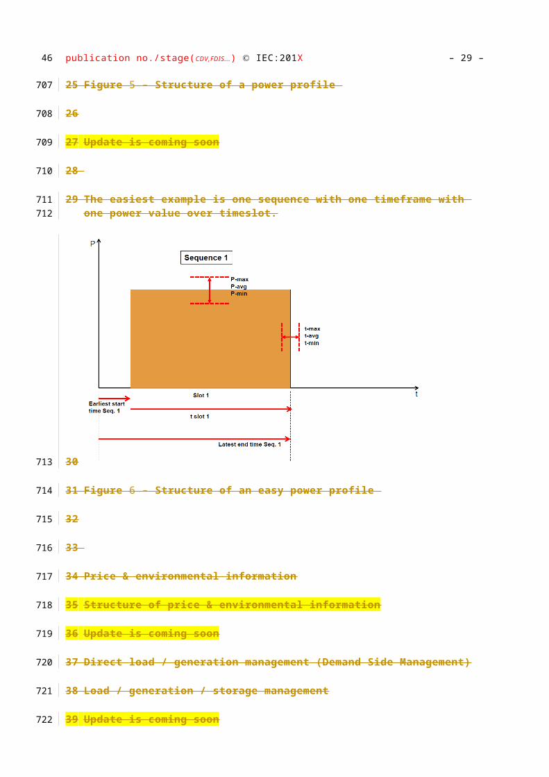
The easiest example is one sequence with one timeframe with one power value over timeslot.
Figure 6 – Structure of an easy power profile
Price & environmental information
Structure of price & environmental information
Update is coming soon
Direct load / generation management (Demand Side Management)
Load / generation / storage management
Update is coming soon
Emergencies
Update is coming soon
Comfort
Notifications, alerts, status information
3839
614
615616
617
618
619
620
621
622
623
624
625
626
627
628
629
630

publication no./stage(CDV,FDIS...) IEC:201X– 27 –
Remote management
Update is coming soon
Upcoming applications
Target to allow smooth hamonization
Like AAL, security, healthcare, .....
Update is coming soon
40
631
632
633
634
635
636
637

– 28 – publication no./stage(CDV,FDIS...) IEC:201X
Requirements
1.1 Common architecture model - A a rchitectural requirements
The architecture, shown in this Technical Draft, is focusing on in-home architectural requirements, whereas other parts of IEC TS6 6 2746-3 describes the architecture on the grid side.
The architecture below is the functional reference diagram, described in the Smart Grid Coordination Group – Working Group Sustainable Processes Report [1].
In this logical architecture the Smart Grid Connection Point represents the interface from the Grid into the premises. The CEM provides the flexibility of connected smart devices, through the energy management gateway, while the smart metering and the simple external consumer display provide a number of functionalities which are described in more detail in work of the Smart Meters Coordination Group. The energy management gateway communicates with the metering channel and the smart metering through the Smart Metering Gateway. The gateways in this architecture split different networks (Wide Area Network, Neighborhood Area Network and Local Area Network) and may be, as further described below, integrated with other functional entities.
The Customer Energy Manager (CEM) is the central managing function. It decides and manages based on information coming from the grid and/or from the Smart Devices. The term “Energy” within CEM reflects the demand of SG CG to focus on Energy. In a typical home or building environment this manager will likely manage all kinds of future management scenarios and will be the basis for AAL (Ambient Assistant Living) and other future User Scenarios.
Figure 7 – Flexibility Functional Architecture (Smart Grid Coordination Group Sustainable Process (EU M490))
Note that the actors in the above architecture are functional entities, which means that some of them may be part of the same physical device (e.g. CEM functionality may be part of a smart device, the smart meter might also encompass the smart metering gateway and CEM, etc…). This will be detailed via examples further below.
The external actors A and B, identified in this functional architecture represent (systems of) market roles that communicate through the Smart Grid Connection Point (SG CP). Examples
4142
638
639
640641642
643644
645646647648649650651652653
654655656657658659
660
661662
663664665666
667668
publication no./stage(CDV,FDIS...) IEC:201X– 29 –
of these roles are Grid operator, meter data collector, meter operator, aggregator, supplier, flexibility operator, etc.
The actual role of actor A or B depends on the local market organization in a member state and competition. In the scope of this report, actor A is defined as the external actor communicating with the energy management gateway while actor B is defined as the external actor communicating with the smart metering gateway.
For sake of simplicity, the use cases in this Technical Report do not represent the energy management gateway and the smart metering gateway - when developing the use cases, we assumed that the gateways do not provide functionalities contributing towards the goals of the use cases. These do however provide functionality in terms of routing information, translation of protocols, device management, security and service capabilities
Within this Home Area Network architecture, 3 main different interfaces are necessary to support Interoperability between:
1) Smart Grid Connection Point & Customer Energy Manager via Energy Management Gateway
2) Smart Grid Connection Point or Smart Meter & Customer Energy Manager via Smart Metering Gateway and Energy Manager Gateway
3) Customer Energy Manager and a smart device.
Figure 8 – Interfaces of Flexibility Functional Architecture
Note: a Smart Device can be in a range of very simple up to very complex devices
Add Methodology SG CG report (Teus) in the annex or in the beginning
The main target of this document is to derive messages necessary to ensure interoperability between Smart Grid, CEM and Smart Devices.
These messages are defined on a neutral basis (based on a technology independent neutral interface). This implies that we are talking about application level and do not describe specific protocol relevant messages on lower ISO/OSI levels
43
669670
671
672673674675
676677678679680
681682
683684
685686
687
688
689
690
691
692
693694
695696697

– 30 – publication no./stage(CDV,FDIS...) IEC:201X
Therefore, this document does neither intend to define the mapping onto domain- specific transmission technologies nor requests specific technologies for in-home connectivity. Mappings are the responsibility of domain specific protocol owners . However, this also implies that messages are transferred to mappings (types of devices, supported by domain specific protocols).
The following diagrams describe the end-point architecture
Figure 9 – Neutral interfaces
[Type a quote from the document or the summary of an interesting point. You can position the text box anywhere in the document. Use the Text Box Tools tab to change the formatting of the pull quote text box.] Replace Neutral Messages with Information to be exchanged ??????????????? it seems to confuse ?????
4445
698
699700701702703
704
705
706
707
708709

publication no./stage(CDV,FDIS...) IEC:201X– 31 –
Figure 10 – Mapping I/F structure
In this context the CEM may use a different set of messages to manage Smart Devices as for the exchange with the grid (see following diagram).
46
710711
712713
714
715716
717

– 32 – publication no./stage(CDV,FDIS...) IEC:201X
Figure 11 – Mapping of messages
As already mentioned above, the CEM may act as a central management system, while parallel working CEMs may also coexist.
4748
718
719720
721
722
723724

publication no./stage(CDV,FDIS...) IEC:201X– 33 –
Figure 12 – Different CEM configurarions
The following diagram lists example mappings of “logical boxes” to physical device combinations
CEMCEMe.g.part of of automationautomation
CEMCEMe.g.part of of automationautomation
SMSMSMSM
ApplianceApplianceApplianceAppliance EVEVEVEV PVPVPVPV
Household or BuildingHousehold or Building
SMSMMeteringMeteringSMSM
MeteringMetering
CHPCHPCHPCHP
•• One device, directly connected, One device, directly connected, e.g. CHP or heat pumpe.g. CHP or heat pump
•• together with associated together with associated Smart MeteringSmart Metering
CEMSCEMSe.g.part of of automationautomation
CEMCEMCEMCEM
49
725
726
727728

– 34 – publication no./stage(CDV,FDIS...) IEC:201X
Figure 13 – Physical combinations
Update is necessary, colors
CEMs may be cascaded. This however is not subject of this Technical Report. The following diagram shows the interfaces which need to be according other parts of IEC TR 62746-x
5051
729
730
731
732
733
734735

publication no./stage(CDV,FDIS...) IEC:201X– 35 –
Figure 14 – Cascaded CEM architecture
SG CP : add picture from JP with modifications
52
736
737
738
739

– 36 – publication no./stage(CDV,FDIS...) IEC:201X
1.2[51.1] Communication requirements for the Smart Grid and the Smart Grid Connection Point (interface into the premises)
The communication system and protocol on the grid side for connecting the smart customers shall fulfill the following requirements:
a) Many customers (resources) can be in parallel connected to a server (> 1 million).
b) The system has to be optimized for a high volume of small data packets.
c) Information about network availability (presence) is required.
d) Notifications and messages shall be “just-in-time” (within seconds) without store-and-forward or continually polling.
e) Resources shall have a unique, trusted identity. This identity may be used as a logical address for communications.
f) Communication shall be encrypted and authenticated from both sides (trusted entities).
g) The communication network must be decentralized with straightforward federation.
h) Server to server communication shall be supported.
i) Message content based on XML shall be extensible. If a message contains additional information not understood by a device, it shall be ignored and the sender must realize and accommodate for this fact. Must be able to define new payload types without ‘breaking’ interfaces.
j) Resources shall not be required to accept inbound connections, where there shall not be the need to open ports in firewalls to allow them to communicate over the internet. Resources will only make outbound connections to the communication infrastructure using their credentials.
k) Resources must be able to receive messages asynchronously, without the need to poll a controller.
l) It must be possible to address a message to a specific endpoint, whether the destination may be a device that controls a resource or application software used to manage resources.
m) Group communications (multi-party interactions) shall be supported, where a controller can address a message to all members of a group. Devices may have membership in zero or more groups. This means that each message shall have a single source, but potentially many destination addresses where a destination address may be a group address that is maintained and managed by the communication infrastructure.
n) The protocol shall support publish and subscribe.
o) The protocol shall support service discovery.
p) The communication system shall support redundancy.
q) The communication system must protect against denial of service attacks and other types of attacks as appropriate for the communication mechanisms.
5354
740741
742
743744
745
746
747
748749
750751
752
753
754
755756757758
759760761762
763764
765766767
768769770771772
773
774
775
776777
778

publication no./stage(CDV,FDIS...) IEC:201X– 37 –
1.3[51.2] Common messages – information to be exchanged
As already mentioned the main intention of this document is to define requirements for the communication between Smart Grid Connection Point and premises as well as between peers within premises. C ommon messages are the vehicle to understand each other. This chapter collects relevant data model requirements for these messages and describes the process used .
1.3.1 Intention of User Stories and Use Cases
Why user stories and use cases?
Standardization does not standardize use cases. The user may use different ways to get to a target or the manufacturer may implement different solutions, means different interpretations of use cases. However the definition of messages and information flows between then different stake holders are essential to ensure interoperability.
Use cases help to collect requirements for necessary messages by describing possible scenarios.
This document recommends messages necessary to ensure interoperability and also defines the requirements for these messages as well as description of the functionality and information flow.
It is then up to the specific Technical Standard (e.g. other parts of IEC 62746) to standardize the messages inclusive the structure and content of the elements.
As Smart Grid, Smart Building and Smart Home are overlapping areas this document describes the whole chain from the grid interface into the premises via in-home/-building distribution until the Smart (End) Devices and vice versa.
The following diagram describes the process to define signal message s and data models structures.
55
779
780781782783784
785
786
787
788789790791
792793
794795796
797798
799800801
802
803804

– 38 – publication no./stage(CDV,FDIS...) IEC:201X
Figure 15 – User Stories & Use Cases process
Note: the last step “Content of messages & XSD structure” is not part of this document as explained already.
In order to define requirements for signals/ messages and related data models, we have chosen a divide-and-conquer process described below.
The first step of the process is collecting “user stories”. Each ”user story” is a description of a typical scenario that a consumer may experience with Smart Grid and in the Smart Home area . The user stories are derived from stakeholder brainstorming sessions, Generic Use Cases (e.g. listed in IEC TC8 WG6) or use cases made by other activities. Each user story is made from the consumer perspective and describes how consumers interact with Smart Grid and/or Smart Home related scenarios in their premises.
5657
805
806
807
808
809
810
811
812813
814815816817818819

publication no./stage(CDV,FDIS...) IEC:201X– 39 –
The second and third step of the process are is creating “building-block” Use Cases. The building-block Use Cases are small Use Cases. These use cases represent one step to realize the services described in the User Stories. Each building-block Use Case includes small numbers of messages transmitted between Smart Device and CEM as well as between CEM and Smart Grid Connection Point. Treating use cases as small parts of services allows us to easily check exhaustiveness of covering user stories by the building-block use cases list.
The forth last part of this step of the process is a verification step by checking the exhaustiveness of building-block use cases covering all user stories.
After confirming exhaustiveness of use cases, the requirements of data models for signals/ messages are examined as the fifth third step and fourth step . The small building-block use cases make deriving the requirements of data models easy.
This step of the process also ends with is a verification step by checking the exhaustiveness of messages covering all use cases.
The last step of this process defines content of messages and global xsd structures. These can be used as a kind of blueprint for Technical Standards in the Smart Grid and Smart Home area.
Note: Definition of messages and XSD structures are not part of this Technical Report
Update necessary due to updated process
[51.2.1] Relationship of User Stories and Use Cases
This document provides descriptions of User Stories and Use Cases.
User Stories are produced from the consumer perspective and describe typical scenarios that a consumer may experience. The list of User Stories is not exhaustive. User Stories are mapped to more detailed Use Cases, such that one User Story may be realized using one or more Use Cases.
In line with the approach taken in the SGCG SPWG Technical Report [1], Use Cases are described in a hierarchical manner in this report. The highest level corresponds to the Generic Use Cases described in [1] and [REF 2]. Additional Generic Use Cases are described in this report in the case that either User Stories are not fully supported by the Generic Use Cases in [1] or alternative Generic Use Cases also apply to User Stories. The requirement for additional Generic Use Cases is identified by validating that a User Story may be fully realized by the existing set of Generic Use Cases – if this is not the case, then an additional Generic Use Case is required.
Within each Generic Use Case category, more detailed Use Cases, or “Specialized Use Cases” are described. These Specialized Use Cases may describe alternative realizations of either components or the entirety of a Generic Use Case. The requirement for additional Specific Use Cases is identified by validating that a User Story may be fully realized by the proposed set (or sets) of Specific Use Cases – if this is not the case, then an additional Specific Use Case is required.
Specific Use Cases list a set of data items and signal message s required for their operation, detailed further in late sections of this document.
This is depicted in the following Figure.
58
820821822823824825826
827828
829830831
832833
834835836
837
838
839
840
841
842843844845
846847848849850851852853
854855856857858859
860861
862

– 40 – publication no./stage(CDV,FDIS...) IEC:201X
Figure 16 – Relationship User Stories and Uas Cases
Update: see final consensus picture (from Shobatake-san)
Update colors
5960
863
864
865
866
867

publication no./stage(CDV,FDIS...) IEC:201X– 41 –
[51.2.2] Example of a complete process cycle
[51.2.3] User Story “The user wants to get the laundry done by 8:00pm”
[51.2.4]
[51.2.5] The user prepares the washing machine
[51.2.6] Fills clothes
[51.2.7] Selects washing program
[51.2.8] Pre-selects the end time (e.g. 8:00pm)
[51.2.9] Starts washing program
[51.2.10] The washing machine now informs the CEM about
[51.2.11] The start of the new program
[51.2.12] The pre-selected end time
[51.2.13] The expected power consumption profile with duration and (e.g. time related specific) energy consumption
[51.2.14] The CEM calculates the operation plan and takes into account
[51.2.15] The pre-selected end time
[51.2.16] The pre-selected incentive program (if not already stored)
[51.2.17] The expected power consumption profile with duration and (e.g. time related specific) energy consumption
[51.2.18] Tariff information
[51.2.19] Expected energy consumption other Smart Devices
[51.2.20] The CEM sends the calculated start time to the Smart Device (washing machine)
[51.2.21] In case the situation changed, a CEM may send an updated starting time unless the Smart Device started
[51.2.22] The Smart Device starts the cycle based on the calculated start time
61
868
869
870
871
872
873
874
875
876
877
878
879880
881
882
883
884885
886
887
888889
890891
892
– 42 – publication no./stage(CDV,FDIS...) IEC:201X
[51.2.23] Use Case UC1.1 - Smart Device (SD) informs CEM - ( Interaction diagram)
[51.2.24]
[51.2.25] Short description required
[51.2.26]
[51.2.27]
sd UC1.1 - SD informs CEM
CEM
(from Actors List)
Actor A / Actor B (SmartGrid)
(from Actors List)
Smart Device
(from Actors List)
SD informs CEM about flex start()
SD informs CEM about duration of program(duration)
refer WGSP 2111-1: SD informs CEM about estimatedenergy consumption(energy profile)
SD informs CEM about latest end time(end time)
6263
893
894
895
895
896
897
897
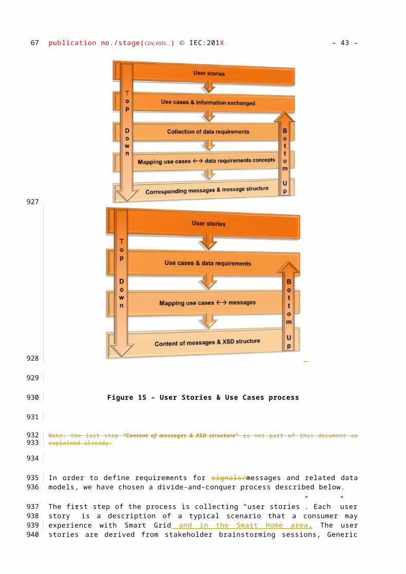
publication no./stage(CDV,FDIS...) IEC:201X– 43 –
[51.2.28] Data Model Requirements “powerFlexibilitiesReport requirements” :
[51.2.29]
[51.2.30] Basic goal: Receive the power flexibilities of a smart device / resource
[51.2.31] Shall be able to transport different modes of a device with different flexibilities (e.g. the switch between charge and feed-in of a battery storage)
[51.2.32] For each mode, shall be able to transport an energy curve with flexibilities
[51.2.33] For each mode, shall be able to transport constraints (earliest start time, latest finishing time etc.)
[51.2.34] For each mode, shall be able to transport different segments of a single curve, each with its own constraints
[51.2.35] Shall make choices for flexibilities and modes available
[51.2.36]
64
898
899
900
900
901902
903
904905
906907
908
909

– 44 – publication no./stage(CDV,FDIS...) IEC:201X
[51.2.37] Content of message & XSD structure:
[51.2.38]
[51.2.39] A device cycle is described using 4 steps:
[51.2.40] The scope is important. Is the device delayable, or can it just forecast? What is the basis of an information for delaying a device (water, gas, electricity?). Which options of operation are available (e.g. I can offer 3 modes of a battery storage: Charge, Discharge or idle).
[51.2.41] How does a cycle for a device mode look like? A washer might say: I have a cycle which takes 2h.
[51.2.42] How does the power consumption for a device mode look like? The washer might say: During my washing cycle, I consume an average of 2kW of electricity, a minimum of 5W and a maximum of 3kW.
[51.2.43] Which flexibilities can a device offer? A washer might say: Based on my users settings, I can be delayed by a maximum of 5h.
[51.2.44] Note: for detailed description and XSD structure look at chapter 9
[51.2.45]
[51.2.46] powerSequenceDescription
[51.2.47] Gives basic information about the commodities a device can be adapted for (e.g. for water, gas or electricity). It might also support multiple views for different processes (e.g. flexible usage of water consumption, electricity consumption etc., based on the CEM preferences).
[51.2.48] XSD:
6566
910
911
912
912
913914915916
917918
919920921
922923
924
925
926
927928929930
931
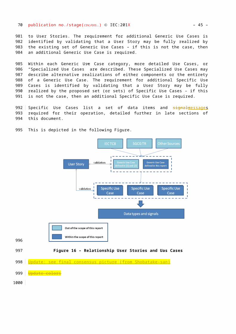
publication no./stage(CDV,FDIS...) IEC:201X– 45 –
[51.2.49]
[51.2.50]
[51.2.51]
[51.2.52] powerTimeSlotSchedule
[51.2.53] Describes the “X-axis”, such as the washing cycle duration. A device cycle is divided into “slots” purely for data modelling. Typical examples of different slots for a washing cycle are: Slot 1 is pre-heating, slot 2 is washing, slot 3 is tumbling. A device might only expose 1 slot (averaging the whole cycle) or a list of slots (e.g. 3 different slots for the 3 different stages of washing). Time information can either be encoded in relative time or in absolute time.
[51.2.54] XSD:
[51.2.55]
67
932
933
934
935
936937938939940941
942
943
944

– 46 – publication no./stage(CDV,FDIS...) IEC:201X
[51.2.56]
[51.2.57] powerTimeSlotValue
[51.2.58] Gives information about the “Y-Axis”. For each device cycle, gives information about the power consumed or produced for a slot. It can also contain information about maximum and minimum power consumption for a slot.
[51.2.59] XSD:
[51.2.60]
[51.2.61]
[51.2.62]
[51.2.63] powerTimeSlotScheduleConstraints
[51.2.64] A device can have different constraints for its operation. A user might choose, that he wants his washer to be delayed for a maximum of 5h. For more complex devices, there might be constraints when moving different slots of a sequence around.
[51.2.65] XSD:
[51.2.66]
6869
944
945
946947948
949
950
951
952
953
954955956957
958
959
960

publication no./stage(CDV,FDIS...) IEC:201X– 47 –
[51.2.67]
[51.2.68] Communication header
[51.2.69] XSD:
[51.2.70]
[51.2.71]
[51.2.72]
70
960
961
962
963
964
965

– 48 – publication no./stage(CDV,FDIS...) IEC:201X
[51.2.73] R equirements for d ata exchanged
This following table is a collect ion of data model requirements from the use cases ( l ist of information to be exchanged ) as described in the previous process description .
Concepts and mappings to use cases are listed in the next chapter
Data
power information
measurement value
Data model requirements
global data models
Data model requirements
Categories
Name Relation
Includes Details / comments
global data models
unit of measurement
e.g. W, kW, l, m³, °C, °F
currency e.g. €, $
value numerical value, to be used by different means
measurement value
1 unit of measurement
1 value
energy direction consume, produce
confidence level measured, estimated, Smart Meter value
relative time now + HH:mm:ss
absolute time HH:mm:ss
time 0…1 relative time
0…1 absolute time
time_span time HH:mm:ss
7172
966
967968
969

publication no./stage(CDV,FDIS...) IEC:201X– 49 –
earliest_start_time time relative or absolute time
latest_start_time time relative or absolute time
earliest_end_time time relative or absolute time
latest_end_time time relative or absolute time
time_of_read time relative or absolute time
Data model requirements
Categories
Name Relation
Includes Details / comments
time_period 1 time
1 time-span
remaining time time span
date format to be specified
UTC UTC defined time format
time zone UTC +- timezone difference HH:mm
weekday Mo, Tue, Wed, …
calendar week 1….52
text messages e.g. warning messages, errors, notifications...
error codes value
no of devices 0…1 individual device
0…1 total no of devices
management & monitoring collection of different stati
some can be used as commands
dim dim level 0 …100 %
temperature type °F, °C
temerature 1 temperature type
73

– 50 – publication no./stage(CDV,FDIS...) IEC:201X
1 value
7475

publication no./stage(CDV,FDIS...) IEC:201X– 51 –
Data model requirements
Categories Name Relation Includes Details / comments
status off
on
ready / idle
flexible start programmed / waiting for start
running
pause
operation on hold / waiting mode
abort
finished
error
dim
temperature
remaining time
charging
discharging
…….
76
970

– 52 – publication no./stage(CDV,FDIS...) IEC:201X
Data model requirements
Categories Name Relation Includes Details / comments
power profile data models
slot ID 1...n
slot_status inactive, scheduled, running
sequence ID 1...n
sequence_status inactive, scheduled, running
current slot slot ID
current sequence sequence ID
slot slot ID
earliest_start_time
latest end time
time span
1...n measurement value
e.g. min, avg, max values
slot_status
energy direction
sequence sequence ID
earliest_start_time
latest_end_time
sequence_status
1...n slot
How do we describe confidence of informat ion if we want to inform Smart Grid about the forecast confidence level (e.g. about 50% confidence....)
7778
971
972973974

publication no./stage(CDV,FDIS...) IEC:201X– 53 –
Data model requirements
Categories Name Relation Includes Details / comments
power profile 1…n sequence
price & environment data models
commodity type e.g. gas, water, electricity
commodity ID unique identifier for a billed commodity
tier ID unique identifier for a conditional price
benchmark ID unique identifier for additional benchmark information, e.g. CO², % of energy from renewables
benchmark value numerical value
is legally binding true or false
benchkark description
information about benchmark type e.g. CO², kind of renewables
commodity commodity ID
commodity type
energy direction
unit of measurement
tier information tier ID
currency
benchmark benchmark ID
benchkark description
value
time span
79
975

– 54 – publication no./stage(CDV,FDIS...) IEC:201X
Data model requirements
Categories Name Relation Includes Details / comments
price data tier ID
time span
is legally binding
value
commodity prices 1 commodity ID associates a commodity ID to a tier ID and or benchmark ID
0…1 benchmark ID
0…1 tier ID
commodity tier schedule
1 commodity ID defines valid tier for a specific time
1 time span
1 tier ID
1 is legally binding
direct load / generation management
direct load / generation management
emergency management
8081
976

publication no./stage(CDV,FDIS...) IEC:201X– 55 –
Data model requirements
Categories Name Relation Includes Details / comments
device capabilities data models
device capabilities price & environment capabilities, e.g. sending or receiving
power profile capabilites, e.g. sending or receiving
direct loadmanagement capabilities, e.g. sending or receiving
emergency capabilities
management & monitoring capabilities
device ID
manufacturer ID
appliance ID
82
977
978
979

– 56 – publication no./stage(CDV,FDIS...) IEC:201X
User Stories
This section describes a collection of user stories as basis for necessary Use Cases.
User stories describe the behavior from the Customers / Users point of view.
The main target of user stories are to narrate typical behaviors in own premises to validate the use cases used to accomplish the story.
The next diagram list typical user requirements.
Figure 17 – Collection of User Stories
Note: The attached User Stories are not categorized
8384
980
981
982983984
985986
987988989
990
991
992
993
994

publication no./stage(CDV,FDIS...) IEC:201X– 57 –
The user wants to get the laundry done by 8:00pm
The user prepares the washing machine
Fills clothesSelects washing program
Pre-selects the end time (e.g. 8:00pm)
May pre selects the incentive program (e.g. cheapest tariff, greenest power etc.)
Starts washing program
The washing machine now informs the CEM about
The start of the new program
The pre-selected end time
The pre-selected incentive program (if not already stored)
The expected power consumption profile with duration and (e.g. time related specific) energy consumption
The CEM calculates the operation plan and takes into account
The pre-selected end time
The pre-selected incentive program (if not already stored)
The expected power consumption profile with duration and (e.g. time related specific) energy consumption
Tariff information
Expected energy consumption other Smart Devices
Expected local energy generation
Amount of locally stored energy
The CEM sends the calculated start time to the Smart Device (washing machine)
In case the situation changed, a CEM may send an updated starting time unless the Smart Device started
The Smart Device starts the cycle based on the calculated start time
85
995
996
997
998
999
1000
1001
1002
1003
1004
10051006
1007
1008
1009
10101011
1012
1013
1014
1015
1016
10171018
1019
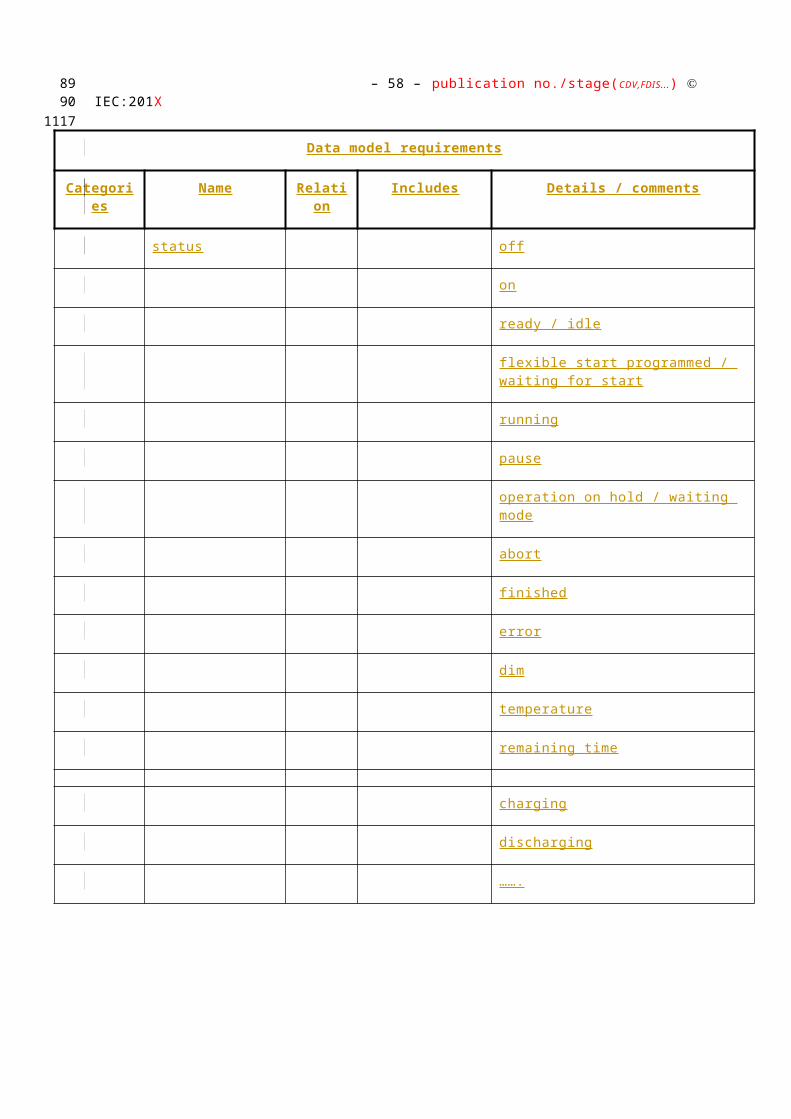
– 58 – publication no./stage(CDV,FDIS...) IEC:201X
The user wants to have his Electro Vehicle charged by 8:00am
The user prepares the EV
Selects charging level
Pre-selects the end time (e.g. 8:00am)
May pre selects the incentive program (e.g. cheapest tariff, greenest power etc.)
Starts charging cycle
The EV now informs the CEM about
The start of the new charging cycle
The pre-selected end time
The pre selected incentive program (if not already stored)
The expected charging consumption profile with duration and (e.g. time related specific) energy consumption
The CEM calculates the operation plan and takes into account
The pre-selected end time
The pre-selected incentive program (if not already stored)
Tariff information
Decentralized Energy forecast, if applicable
The expected power consumption profile of the requested EV charging
Expected energy consumption of other Smart Devices
Expected local energy generation
Amount of locally stored energy
The CEM sends the calculated start time to the EV
In case the situation changed, a CEM may send an updated starting time unless the Smart Device started
The EV starts the cycle based on the calculated start time
EDITOR NOTE: NEED TO ADD A GENERAL USER STORY INVOLVING SAFETY ASPECTS. For example, in the case of battery charging (EV or otherwise): If, at any time during this process, the EV determines that it is unsafe to start or continue charging, then it informs the CEM. The CEM then takes appropriate action.
8687
1020
1021
1022
1023
1024
1025
1026
1027
1028
1029
10301031
1032
1033
1034
1035
1036
1037
1038
1039
1040
1041
10421043
1044
1045104610471048

publication no./stage(CDV,FDIS...) IEC:201X– 59 –
The grid recognizes (severe) stability issues
The grid sends a load control signal , requesting the CEM to adjust the load (by either increasing or decreasing consumption or generation). The load control signal may include
an incentive value and/or time frame for answering to the request
an incentive value and/or time frame for acting on the request
Depending on user configurations, several options are possible:
The user allows the Customer Energy Manager to adjust the load of some of his devices (e.g. of the freezer for a defined/maximum time). The support of these capabilities may usually be part of a contract between Energy Supplier and customer.
After receiving the request from the grid, the CEM checks the status of attached Smart Devices checking on the possibility of e.g. reducing consumption by xW, x% of consumption or alternatives which leads into a change in consumption / generation
The Smart Device may react so and may respond with the achieved details
The CEM may send the response back to the grid.
The CEM checks the status and may recalculate (e.g. postpone) the starting time of already planned upcoming cycles ( see x.x.x, y.y.y )
The CEM updates starting time of Smart Devices
CEM feeds own battery pack energy into own network or into the grid
The CEM checks status of battery pack
In case the battery pack can provide enough energy the CEM can decide to start feeding process
CEM stores additional energy from the grid into own battery pack
The CEM checks status of battery pack
In case the battery pack has enough capacity and if the energy price plus the incentive value is better than the average cost of stored energy, the CEM starts feeding process
88
1049
105010511052
1053
1054
1055
105610571058
105910601061
1062
1063
10641065
1066
1067
1068
10691070
1071
1072
10731074

– 60 – publication no./stage(CDV,FDIS...) IEC:201X
Limitation to fixed amount of power
The user wants to limit his consumption to his own local production (e.g. PV)
The user instructs the CEM to limit power consumption up to amount of own decentralized power. Along with this command, several additional parameters may be set, for example:
At which time of the day this limit applies
Which devices are exempt from this limit
…
The CEM is kept informed on total power consumption and generation through the smart meter.
When managing power consumption in the house, the CEM takes into account the above limits and parameters.
If the user wants to start a smart device, then the CEM is notified by the smart device and receives, amongst others, a load profile (see 3.1.1).
If, when based on the load profile and other parameters, the CEM concludes that the power limit will be exceeded, then it may send a warning signal to the relevant device and to a display if one is available.
Based on the warning signal , the user may decide to postpone his consumption or to manually overrule the power limit.
Furthermore there is the possibility that premises go in isolated (island) operation from the distribution system. Such premises will be isolated or "switch of" by the network operator or by premises own control facilities based on appropriate monitoring arrangements. The ability of island operation comes from the fact that they are able to cover their own power demand by premises own "distributed" generator and/or storage facilities, i.e. batteries. In such situations the distribution network can be in operation or out of service due to emergency situations and/or planned maintenance and/or repair activities. Premises with their own generation and storage facilities can cover their total demand or at least part of their total demand controlled by a Customer Energy Management system with or without being connected to the distribution network. In normal situations surplus of energy generated by the premises can be delivered back to the distribution system. Reconnecting the premises to the distribution system after a period of island operation has to be arranged in a safe and coordinated manner. That can be arranged by a synchronizing facility/unit with build-in monitoring and control arrangements; the latter can be part of the fore-mentioned CEM.
CEM manages Simple Devices
Switch on/off simple devices, dim simple devices
Examples are turning on/off simple devices such as lighting, smart plugs and dimming lighting etc.
8990
1075
1076
107710781079
1080
1081
1082
10831084
10851086
10871088
108910901091
10921093
109410951096109710981099110011011102110311041105110611071108
1109
1110
11111112

publication no./stage(CDV,FDIS...) IEC:201X– 61 –
The Customer wants to sell his flexibility to the grid
Based on information on:
Current consumption (received from smart meter)
Currently running devices and their load profiles
Device assignments to be ran and their load profile
Tariff information
Information on power limitations
the CEM may identify opportunities for flexibility.
The user may have set constraints on the flexibility that may be offered to the grid. These constraints may be:
Which loads (or generators) and user specified conditions are available for providing flexibility
Start time of the flexibility (start time within a certain time period)
Duration of the flexibility
Amount of flexible power at a point in time
Amount of flexible energy
The CEM proposed this flexibility to the grid, by providing the following information:
Start time of the flexibility (start time within a certain time period)
Duration of the flexibility
Amount of flexible power at a point in time
Amount of flexible energy
These offerings are negotiated by a process of offering, accepting or rejecting, possibly. Reasons for accepting and rejecting include suitability of the offered flexibility (the expected value of the flexibility in e.g. a portfolio) and financial aspects.
If the grid wants to accept the offer, it sends a message indicating this and with the incentive that is related to the acceptance (this is the Flexibility Offer Acceptance)
A second message from the grid indicates how the flexibility should be allocated. This message comes in the form of a load profile, but stays within the constraints of the flexibility offer.
The CEM implements the flexibility allocation by adjusting the (time of the) consumption / generation of devices on the premise.
91
1113
1114
1115
1116
1117
1118
1119
1120
11211122
11231124
1125
1126
1127
1128
1129
1130
1131
1132
1133
113411351136
11371138
113911401141
11421143

– 62 – publication no./stage(CDV,FDIS...) IEC:201X
The Customer wants to sell own decentralized energy (e.g. PV) to Smart Grid
When the consumer wants to sell his own decentralized energy to the grid, several options are possible:
Based on a price signal or load/generation control signal , CEM may instruct local generators / storage to adjust output (…...).
CEM offers to sell an amount of energy at a specified price, this corresponds to offering flexibility as described under…...
CEM releases stored energy (see …...)
EDITOR NOTE: NEED TO CONSIDER/CHECK COMBINING THESE WITH THE APPROPRIATE JAPANESE USER STORIES
Grid related Emergency Situations (Blackout prevention)
The grid is close to a black-out and will soon have to cut off sections of the grid.
As a means of preventing this by limiting the overall energy consumption to a certain minimum, the grid sends an emergency signal to all connected households in order to instruct them to place their connected devices into “emergency connected off mode”.
Assumption: The CEM and smart devices are pre-configured with an “emergency connected off mode” profile. This profile defines which connected devices enter “emergency connected off mode” and what that mode entails (on a device by device basis). This profile is agreed by both the consumer and the energy provider and is likely to be included in a contract.
The CEM receives an emergency signal (some low consumption, essential devices like gas boilers that require a minimum of electricity to run, may be allowed to stay operational – this will be defined within the profile).
This signal may include the duration of the emergency period.
The CEM sends a signal to all connected smart devices to switch to “emergency connected off mode”.
The devices switch to “emergency connected off mode”.
When the emergency period has ended (either because the predetermined emergency time has passed or because the grid sent a message that the emergency has passed), the CEM instructs the devices that they may resume operations as normal.
EDITOR NOTE: NEED TO ADD: green, yellow and red diagram from SG CG, may be in former sections
The customer wants to connect a new smart device to the CEM
Installer and/or “plug and play” consumer installation will be supported
Discovery, authentication etc. are handled by lower layers and are out of scope of this document
9293
1144
11451146
11471148
1149
11501151
1152
1153
1154
11551156
1157
1158
1159
116011611162
11631164116511661167
116811691170
1171
11721173
1174
117511761177
1178
11791180
1181
1182
11831184

publication no./stage(CDV,FDIS...) IEC:201X– 63 –
Communication signal s and data used between the CEM and Device concerning the capability (type and functionality) of the device are within the scope of this document
A smart device disconnects unexpectedly (failure)
The CEM and smart device exchange regular signal s or status messages to keep each other informed of their connection (to the network) and of their operational status.
At a moment in time, the CEM does not receive such a message from a device when it expected one.
The CEM sends a status request to the device.
In case the CEM does not receive a response or when the device responds with an abnormal status, the CEM sends a warning message to an advanced display. The CEM may also send a warning to a third party (e.g. service provider) on the grid side.
The consumer wants to be informed on their historic and forecasted energy use
The consumer indicates on the CEM User Interface that they want information on their historic and forecasted energy use.
In case the CEM does not have the relevant historic information, it may request this data from the smart meter or other source.
Based on the information related to currently connected devices and their expected consumption and generation and based on the historic data, the CEM may build a short term energy forecast and informs the user.
The consumer wants to know an estimate of the yearly energy cost of a smart device
(This user story assumes that the CEM or the device stores information on time-of-use consumption of individual devices and that the CEM has a historic record of time-of-use buckets and their related tariffs in the relevant currency).
The consumer indicates on the CEM User Interface that they want information on the yearly cost of a specific device.
The CEM collects information of individual device’s consumption from its memory or requests this information from the device.
The CEM collects information related to historic time-of-use buckets and tariff information expressed in financial units from its memory.
The CEM combines (estimated) consumption information with tariff information and sends the response to the consumer’s query back to the CEM User Interface.
The consumer wants a storage device to feed energy to the grid once the tariff reaches a certain threshold
The consumer parameterizes the CEM to feed energy once the tariff for selling energy reaches a certain threshold. Additionally, the consumer may parameterize that local storage should not drop below a certain point
The CEM receives a new tariff from the grid (may be via the smart meter) and notices that this tariff exceeds the abovementioned threshold.
The CEM may check:
Whether the amount of stored energy is not below a user specified point
94
11851186
1187
11881189
11901191
1192
119311941195
1196
11971198
11991200
120112021203
1204
120512061207
12081209
12101211
12121213
12141215
12161217
121812191220
12211222
1223
1224

– 64 – publication no./stage(CDV,FDIS...) IEC:201X
Whether releasing stored energy to the grid would be inconsistent with other user commands / settings (e.g. electric vehicle that must be charged by a specific time, flexibility assignments, load control signal s requesting to increase consumption or lower generation, etc…)
When there is no conflict with the abovementioned points, the CEM instructs the storage device to feed energy in the grid.
Manage energy consumption of smart devices by Smart Grid
This user story explains how on July 15th, a premises customer allows the supplier (or energy service provider) to raise the temperature setting of his air-conditioner in a defined range so as to curtail power demand for a specific time.
On the 14 th of July, the supplier requests a reduction of power consumption by tomorrow, July 15, from 10:00 am to 2:00pm.
The customer finds the request and confirms that he is willing to comply by e.g.
Setting the temperature range to a specific one.
Turning on the air-conditioner
In the morning of July 15, the supplier analyzes the power consumption data continuously delivered through data collectors which accumulate the power consumed by all customers via smart meters, and reconfirms the high demand forecast during the peak period considering the metrological data sent from the weather forecast system.
At 11:00am, given the estimated power demand for the coming hours, the supplier sends signals to the CEM and asks for the possibility to reduce power consumption by 300 W (Power I) from 12:00 am to 2:00 pm.
The CEM informs the air-conditioner about the target of reduction including timeframe.
At 12:00 am the air-conditioner reduces power consumption and communicates this to the CEM. If the requested settings cannot be reached, the air conditioner informs what can be achieved.
9596
1225122612271228
12291230
1231
123212331234
12351236
1237
1238
1239
1240124112421243
124412451246
1247
124812491250

publication no./stage(CDV,FDIS...) IEC:201X– 65 –
Manage in-premises Battery System
This user story explains how a battery owned by premises customers charges (buys) electricity during off-peak period, from 11:00 pm to 5:00 am, and discharges power to use appliances in the house during peak period, 10:00 am to 2:00 pm.
The customer prepares the setting of the battery through the CEM:
Prioritizing the reduction of electricity cost by charging cheaper electricity at off-peak time and discharging power during the peak-period.
The CEM calculates the operation plan based on:
Tariff information, for example;
XX.XX cent/kWh, cheaper electricity, from 11:00 pm to 5:00 am
XX.XX cent/kWh, expensive, from 10:00 am to 2:00 pm.
Expected power consumption based on;
The past power consumption records;
The owner’s today’s schedule
The remaining battery charge
Based on this operation plan, the CEM instructs the battery to charge and discharge in the most optimal way.
Manage Distributed Energy Resources (DER)
Alternative 1: this user story describes how a DER owned by a premises customer generates electricity in peak periods, from 10:00 am to 2:00 pm, to reduce electricity cost.
The customer prepares the setting of the DER through the CEM:
Select the plan that utilizes DER to generate electricity during peak period in a day.
The CEM checks the status of the DER.
The CEM starts the DER at 10:00 am and stop it at 2:00 pm.
Alternative 2: this user story describes how a DER owned by a premises customer generates electricity when a dynamic pricing signal is provided from the supplier to the customer.
The customer prepares the setting of the DER through the CEM:
Select the plan, which initiates the DER operation when a tariff of XX.XX cent/kWh or more of electricity price is offered.
The CEM checks the signal s from the supplier and status of the DER.
At 10:30am, the supplier offers XX.XX cent/kWh from 11:00 am to 2:00pm.
The CEM receives the signal and compares the price with the set value.
The CEM starts the DER if both that the price is equal to or higher than the set value and that the DER is ready are confirmed.
97
1251
125212531254
1255
12561257
1258
1259
1260
1261
1262
1263
1264
1265
12661267
1268
1269
127012711272
1273
1274
1275
1276
1277
127812791280
1281
12821283
1284
1285
1286
12871288

– 66 – publication no./stage(CDV,FDIS...) IEC:201X
The DER generates electricity from 11:00 am to 2:00 pm.
If after 2:00 pm the tariff no longer exceeds the abovementioned threshold, the CEM instructs the DER to stop generation.
9899
1289
12901291
publication no./stage(CDV,FDIS...) IEC:201X– 67 –
Peak Shift Contribution by Battery Aggregation
The customer likes to participate in the Peak Shift Contribution of Battery Aggregation (PSCBA) according to the conditions such as the maximum and minimum value of Customer’s Battery output power that are specified by the customer. Under the contract between the electric company and the customer, battery SCADA and the CEM communicate with each other.
The customer lets CEM participate in the PSCBA.
Battery SCADA sends “request for Schedule” to the CEM.
The CEM sends the requested schedule to Battery SCADA. This includes Detail Schedule/ Outline Schedule/ Surplus Schedule of Customer’s Battery.
Battery SCADA calculates the total surplus potential and the schedule of batteries.
According to the plan for PSCBA set by Gird Operator, Battery SCADA calculates the schedule of each battery for the plan.
Battery SCADA sends “inquiry” command to CEM. This includes the plan for PSCBA corresponding to Customer’s Battery.
CEM sends the response of “inquiry” message to Battery SCADA. This includes “inquiry rejection” or “inquiry acceptance”
In case of “inquiry acceptance”, Battery SCADA sends “execution notification” to CEM.
CEM sends charging/discharging command to Customer’s Battery according to the Customer’s detail schedule and the plan for PSCBA corresponding to Customer’s Battery.
Control of Smart home appliances based on price information by time slot
The user likes to use a water heater, air conditioner and other appliances such that total electricity charges are relatively less.
The user instructs the CEM to program the water heater, air conditioner and other appliances following a number of conditions.
The user inputs operating conditions of each appliance at CEM, e.g.:
Water heater temperature 90C, water level 50%
Air conditioner mode: cooling down, wind: auto, temperature: 27C
The user inputs time conditions (desirable start time, desirable finish time) of each appliance at CEM, e.g.:
Water heater finish by AM7
Air conditioner finish cooling down by AM10
The electricity tariff information is issued at noon every day for the following 24 hours.
Based on the input conditions, time conditions and tariff, the user lets CEM calculate a program for the following day such that total electricity charges are relatively less
CEM calculates an operating plan for those appliances considering operation time, power consumption during operation, electricity charges and so forth
The user confirms the calculation results and commits the operating plan to be executed
100
1292
12931294129512961297
1298
1299
13001301
1302
13031304
13051306
13071308
1309
131013111312
1313
13141315
13161317
1318
1319
1320
13211322
1323
1324
1325
13261327
13281329
13301331

– 68 – publication no./stage(CDV,FDIS...) IEC:201X
CEM controls each appliance as programmed according to conditions of operating plan
101102
1332

publication no./stage(CDV,FDIS...) IEC:201X– 69 –
Control of Smart home appliances in response to power saving request from Electric power supplier
The user likes to use a Water heater, Air conditioner and other appliances such that power saving request from electric power supplier is satisfied if possible.
The user instructs the CEM to program the water heater, air conditioner and other appliances following a number of conditions.
The user inputs operating conditions of each appliance at CEM, e.g.:
Water heater temperature 90C, water level 50%
Air conditioner mode: cooling down, wind: auto, temperature: 27C
The user inputs time conditions (desirable start time, desirable finish time) of each appliance at CEM, e.g.:
Water heater finish by AM7
Air conditioner finish cooling down by AM10
At AM7, the CEM receives a request for power saving from PM1 to PM5.
The user lets CEM calculate a program at AM8 with input conditions such that power saving request is satisfied as possible
CEM calculates to program an operating plan for those appliances before, during and after the requested power saving, considering operation time, power consumption while in operation, electricity charges and so forth
The user confirms calculation results and commits the operating plan to be executed
The user activates the execution of operating plan at CEM
CEM controls each appliance as programmed according to conditions of operating plan
Control of Smart home appliance before power cut
The user likes to use a Water heater, Air conditioner and other appliances before power cut takes place
The user instructs the CEM to program the water heater, air conditioner and other appliances following a number of conditions.
The user inputs operating conditions of each appliance at CEM, e.g.:
Water heater temperature 90C, water level 50%
Air conditioner mode: cooling down, wind: auto, temperature: 27C
The user inputs time conditions (desirable start time, desirable finish time) of each appliance at CEM, e.g.:
Water heater finish by AM7
Air conditioner finish cooling down by AM10
The information is issued at AM7 that a power cut will occur from PM1 to PM5.
The user lets CEM calculate a program at AM8 with input conditions considering power cut informed by electric power supplier
103
13331334
13351336
13371338
1339
1340
1341
13421343
1344
1345
1346
13471348
134913501351
1352
1353
1354
1355
13561357
13581359
1360
1361
1362
13631364
1365
1366
1367
13681369

– 70 – publication no./stage(CDV,FDIS...) IEC:201X
CEM calculates to program an operating plan for those appliances before, during and after the scheduled power cut, considering operation time, power consumption while in operation and so forth
The user confirms calculation results and commits the operating plan to be executed
The user activates the execution of operating plan at CEM
CEM controls each appliance as programmed according to conditions of operating plan
104105
137013711372
1373
1374
1375
publication no./stage(CDV,FDIS...) IEC:201X– 71 –
Control of Smart home Appliances in case of natural disaster
The user likes to use a Water heater and Storage battery at the highest priority in case that unstable electric power supply and/or power cut is expected due to natural disaster
The user presets Water heater and storage battery at CEM to program an emergency operation plan
The user inputs operating conditions of each appliance at CEM
Water heater temperature 90C, water level: 50%
Storage battery mode: quick charge
The user lets CEM calculates a program with input conditions in case CEM receives power alert from electric power supplier
CE¨M calculates an operating plan for Water heater, Storage battery and all other appliances when CEM receives power alert. Such an operating plan could look like the following:
confirm the operating status of all appliances connected to CEM
execute normal shutdown process to all appliances in operation except Water heater and Storage battery
execute operation of Water heater and Storage battery with conditions set by the user
The user inputs auto-execution of emergency operating plan as programmed at CEM in case CEM receives power alert from electric power supplier
CEM receives power alert from electric power supplier at AM10
CEM commences at AM10 + n to control each appliance as programmed according to conditions of operating plan, an example of which is:
continue operating Water heater and Storage battery and execute normal shutdown process to finish as far as CEM does not receive a signal to call off power alert;
execute normal shutdown process of Water heater to finish, and continue operating Storage battery in case that CEM receives power saving request;
continue operating Water heater and Storage battery till start time of power cut and execute normal shutdown process to finish operating before start time of power cut in case that CEM receives power cut information;
execute normal shutdown process to Water heater and Storage battery to finish in case that CEM receives a signal to call off power alert
106
1376
13771378
13791380
1381
1382
1383
13841385
138613871388
1389
13901391
1392
13931394
1395
13961397
13981399
14001401
140214031404
14051406

– 72 – publication no./stage(CDV,FDIS...) IEC:201X
Bilateral Demand Response (Negawatt Transaction= Japanese related requirement)
This user story describes how an energy supplier asks for a demand responsive load from consumer on the day when tightness of electricity supply and demand is expected.
On the day before the event day (at which a supply tightness is expected), the energy supplier indicates a specification of demand reduction, requesting flexibility from the connected consumers / CEMs. The specification/flexibility request contains:
The date,
Time window (event start and event end),
Amount in control area.
Based on information on forecasted energy use and user settings, the CEM proposed flexibility as described under Error: Reference source not found . The consumer can also input this information manually. The resulting bid contains:
Amount of demand responsive load (kW) and
Bidding price (price/kWh).
The energy supplier ranks bids from consumers according to “merit order” and notifies execution results.
Consumers, who made a successful bid, reduce their load in the time window on the specified day..
107108
1407
14081409
141014111412
1413
1414
1415
141614171418
1419
1420
14211422
14231424
publication no./stage(CDV,FDIS...) IEC:201X– 73 –
Use Case mapping (User Stories – Use Cases)
Insert Table
Use cases indicated in BLACK are directly contributing towards the fulfillment of the user story
Use cases indidated in GREY are supporting the user story
Use cases indicated with "GAP" still have to be developed
109
1425
1426
1427
1428
1429
1430
1431
1432

– 74 – publication no./stage(CDV,FDIS...) IEC:201X
Use Cases
[51.3] Introduction
The following use cases are based on the above user stories and the architecture defined earlier in this Technical Report. Note that the use cases only describe communication between Actor A/B, the CEM, the smart meter and the smart devices. For sake of simplicity, these use cases do not represent the energy management gateway and the smart metering gateway - when developing the use cases we assumed that the gateways do not provide functionalities contributing towards the goals of the use cases. In reality, the gateway may provide functionality in terms of routing information, translation of protocols, device management, security and service capabilities .
All use cases are described in detail in Annex 2
Note that several use case scenarios may work together in an iterative way. E.g. there might be a negotiation which uses the price (WGSP2112) to get a forecast (WGSP2111), then adapting the price, which might be binding from there on.
Also note that information can be transferred via different channels to actor A, B and to the consumer or in-home devices. This implies that the use case could effectively be split up into several sub-use cases, each with its own goal.
For the definition of the use cases in this document, the already referenced SGCG architecture model has been used as a basis.
Note that the actors in the above architecture are functional entities, which means that some of them may be part of the same physical device (e.g. CEM functionality may be part of a smart device, the smart meter might also encompass the smart metering gateway and CEM, etc…)
CEM Smart Device*
Simple external consumer
display
Actor AEnergy
management gateway (EMG)
Smart Metering gateway (LNAP )
Smart meter functionalityActor B
Energy Management / Providing Flexibility (M490)
M441 architecture
Market communication
* e.g. HBES device, smart appliances, storage, generator, domestic charger for EV, complex display
Smart Grid Connection
Point
Functional metering reference architecture according the SM-CG (TR50572)
110111
1433
1434
143514361437143814391440144114421443144414451446
1447
144814491450
145114521453
1454
14551456
1457
145814591460
1461

publication no./stage(CDV,FDIS...) IEC:201X– 75 –
[51.4] Actor list
For all use cases, used in this document, following Actors have been used.
112
1462
1463

– 76 – publication no./stage(CDV,FDIS...) IEC:201X
Actors
Grouping (Community) Group Description
Actor Name
see Actor List
Actor Type
see Actor List
Actor Description
see Actor List
Further information specific to this Use Case
Customer Energy Manager (CEM)
Internal
The CEM is a logical function optimising energy consumption and or production based on signal s received from the grid, consumer’s settings and contracts, and devices minimum performance standards. The Customer Energy Manager collects messages sent to and received from connected devices; especially the in-home/building sector has to be mentioned. It can handle general or dedicated load and generation management commands and then forwards these to the connected devices. It provides vice versa information towards the “grid / market”. Note that multiple loads/generation resources can be combined in the CEM to be mutually controlled.
When the CEM is integrated with communication functionalities it is called a Customer Energy Management System or CEMS.
Energy management gateway (not used in this document)
Internal
An access point (functional entity) sending and receiving smart grid related information and commands between actor A and the CEM, letting the CEM decide how to process the events. The communication is often achieved through an internet connection of through a wireless connection.
This gateway may also provide services including protocol conversion, device management, security and service capabilities.
Smart Metering gateway (LNAP) (not used in this document)
Internal
An access point (functional entity) that allows access to one or more metering end devices and, when equipped with an interface, to advanced display / home automation end devices connected to the local network.
A LNAP also may allow data exchange between different functional entities connected to the same LN. The LNAP may act simply as a router transferring messages between the metering end device and/or display/home automation devices and the Neighbourhood network of wide area network.
It may also provide services including protocol
113114

publication no./stage(CDV,FDIS...) IEC:201X– 77 –
conversion, device management, security and service capabilities. Services may be provided as functions of the LNAP itself or provide proxy services on behalf of limited capability devices connected to the local network.
115

– 78 – publication no./stage(CDV,FDIS...) IEC:201X
Smart meter Internal
The metering end device is a combination of the following meter-related functions from the Smart Metering reference architecture:
Metrology functions including the conventional meter display (register or index) that are under legal metrological control. When under metrological control, these functions shall meet the essential requirements of the MID;
One or more additional functions not covered by the MID. These may also make use of the display;
Meter communication functions.
Simple external consumer display
External
Dedicated display screen in connection with the smart meter/SGCP available to the customer to check power consumption, planned load reductions and load reductions historical. Other not dedicated means also exist to deliver consumption information to the customer, such as the personal computer, the mobile phone or the TV set.
Smart device External
A smart device may be an appliance, generator or storage device (Local storage devices include direct and functional electricity storages such as electrochemical batteries, heat pumps and micro CHP such as fuel cells with heat buffers, air conditioning and cooling devices with thermal inertia, etc…) . The smart device can receive data directly from the grid, though an interface with the CEM and can react to commands and signal s from the grid in an intelligent way.
Since the smart device is outside the scope of the SGCG, it must be seen as an external actor
Smart appliance (white goods)
External
An example of a smart device is a smart white goods appliance which is an appliance that has the capability to act in response to a signal from the grid and thereby optimize its behaviour towards the energy supply network. The signal can be received from a utility or a third party energy service provider directly or via a home energy management system,
The signal can be information like the cost of energy or the amount of available renewable energy, or it can be a Demand Respond signal (delay load signal or other related information) that the appliance must receive, interpret and react upon based on pre-set or active consumer input. The smart appliance is not guaranteed to respond, but will do so based on its status and user settings in order to ensure the expected performance.
The consumer has the ultimate control of the appliance and can override any specific mode
116117
publication no./stage(CDV,FDIS...) IEC:201X– 79 –
(e.g. override a delay to allow immediate operation, limit delays to no more than a certain number of hours, or maintain a set room temperature).
Any appliance operation settings or modes shall be easy for an average, non-technical consumer to activate or implement.
Actor A via SG CP
External
External actor (Smart Grid Market Role) interacting with the system functions and components in the home or home automation network through the energy management communication channel.. Examples of such market roles are the Energy Provider, the Energy Services Provider, the aggregator, etc…
Actor B via SG CP
External
External actor (Smart Grid Market Role) interacting with the system functions and components in the home or home automation network through the metering communication channel. This actor is responsible for collecting metering data. Examples of such market roles are the DSO, metering company, etc.
User Internal
.........
[51.4.1] Def inition of specific application concepts
In order to create interoperable messages with the relevant information, specific application concepts need to be explained to become the basis for these messages and dates.
1.3.1.1 Energy Management
1.3.1.1.1 Traffic light concept
The energy management relevant user stories and use cases follow on a certain level the Traffic Light Concept (TLC), described in the “Report WG Sustainable Processes” - CEN-CENELEC-ETSI Smart Grid Coordination Group (SG-CG) - Approval of SG-CG deliverables”. EU Mandate M490, Dec. 2012. [2]
tTransition period from the free market to the fixed order fro
m the grid operator
Marketoperation
Grid operation
0 s forecast and market response are possible
Frequency
Voltage
Wind
Solar
Flexibilitypowerstation
Storage
Conventional powerstationConventional supply
EV
Grid utilitiesload factor
118
1464
14651466
1467
1468
1469147014711472
1473

– 80 – publication no./stage(CDV,FDIS...) IEC:201X
Figure 18 – Traffic Light Concept [3]
The TLC differentiate between 3 areas:
The green shaded region defines the region where the ‘smart market’ competitively operates freely; the DSO may or may not interact with the market at this point. This should be seen as the ‘normal operating state.’
The yellow state indicates the state where the DSO actively engages with the market in order to keep the system from becoming unstable, it is therefore a temporary state preventing the grid from entering the red state. This could be by executing pre-agreed contracts or by stepping in to procure in real time at market prices. This does not mean that the customer has to accept any situation where a third party (DSO) decides when they can use what is in their home or business premise. Instead intelligent solutions and economic incentives should be provided to allow the customer to decide and accept some limits.
In the red state the DSO needs to take control of market interactions in a certain area where the constraint has occurred. However, actions in this state must be specific and well defined and be temporary in nature. In this situation the DSO can override contracts existing in the market, execute dedicated emergency actions through flexibility operators, or execute direct controls over generation or demand in order to re-stabilize the system as far as a contract or regulation / legislation allows to do so.
For details please refer to the above mentioned document . [2]
1.3.1.1.2 Flexibility (Demand Response)
Flexibility is a typical functionality in the green area. The market offers flexible energy based on prices and / or environment. This can be amongst other scenarios the retailer, offering time separated tariffs but also using the own PV energy and combinations of that.
The customer offers flexibility by letting a Smart Device to be started, paused, etc. based on specific conditions like price ranges, the availability of energy or specific environmental requirements (green power etc).
The Smart Device can be a consumer or producer of energy.
1.3.1.1.3 Power profile
Irrespective of whether the Smart Device is a consumer or producer it needs to announce a kind of expected energy consumption or generation (power profile) to allow energy allocation within smart premises.
For example, a heat pump can ask for allocating 2 sequences per day, on c e in the morning, on c e in the afternoon, each sequence with different phases of power consumption.
Alternatively, a smart device can offer multiple sequences for the same time period, e.g. a battery pack can offer charging or discharging. The CEM can to cho ose between these possibilities.
119120
1474
1475
1476
1477
1478
1479
1480
148114821483
148414851486
1487
1488
148914901491
14921493
149414951496

publication no./stage(CDV,FDIS...) IEC:201X– 81 –
This power profile allows to distinguish between “ generation ” or “ consumption ” of energy. This is described by the energy-direction flag (see corresponding date in the tables) , whereas the diagram remains the same.
Figure 19 – Structure of a power profile
The easiest example is one sequence with one timeframe with one power value over timeslot.
Figure 20 – Structure of an easy power profile
121
149714981499
1500
1501
1502
1503
1504
1505

– 82 – publication no./stage(CDV,FDIS...) IEC:201X
1.3.1.1.4 Price & environmental information
The price & environmental profile uses the same basic structure as shown above within power provile . Herewith typical scenarios can be handled like the price table for certai n time slots within a timeframe (e.g. the next 24h).
Additionally benchmark conditions can be used to to address more than one price per time-slot. Th e different price can be based on different conditions. Examples are:
If energy consumption exceeds a certain amount of energy within the time-slot, the next price level will be activated
The price levels reflect benchmarks, e.g. types of energy like renewables, yellow energy, CO² footprint etc. , the customer can select out of
Figure 21 – Structure of a price profile
1.3.1.1.5 Direct load / generation management (Demand Side Management)
1.3.1.1.5.1 Load / generation / storage management
Update is coming soon
122123
1506
1507
1508
150915101511
15121513
15141515
15161517
1518
1519
1520
1521
1522
1523
1524
1525
1526

publication no./stage(CDV,FDIS...) IEC:201X– 83 –
1.3.1.1.5.2 Emergencies
Update is coming soon
1.3.1.2 Comfort , management and status information
This collects data models for remote management as well as kinds of remote monitoring like n otifications, alerts, status information .
The collection includes typical data like on, off, waiting for start, pause, finished etc.
1.3.1.3 Upcoming applications
Target of the data models and corresponding messages are set up in a manner to allow smooth harmonization of upcoming applications like AAL, security, healthcare, and so forth.
124
1527
1528
1529
1530
15311532
1533
1534
15351536
1537

– 84 – publication no./stage(CDV,FDIS...) IEC:201X
Note: for detailed information refer to SGCG SP .... and DKE database
125126
1538
1539
1540

publication no./stage(CDV,FDIS...) IEC:201X– 85 –
[51.5] Energy related use cases
Note: Main parts of these use cases refer to use cases from the Working Group Sustainable Processes (WGSP) of the Smart Grid Coordination Group. These use cases (WGSP 21XX) are also added in Annex A2.
[51.5.1] Energy forecast, price & environmental information (WGSP 2110)
[51.5.1.1] Information regarding power consumption or generation (WGSP 2111)
[51.5.1.1.1] Use Case scenario 1a: SD sends individual power consumption / generation to CEM
Narrative:
The SD sends its power consumption to the CEM. The underlying power profile is explained in chapter 2.1.
This information can comprise:
– The power profile (see chapter 2.1) as new forecast or prognosis (e.g. as input for a flexible start or for washing machine (consumption) or a Photovoltaic system (generation))
– The power profile (see chapter 2.1) as updated forecast for the rest of running cycle
– The power profile (see chapter 2.1) and the actual time and/or slot no. (historical and forecasted within a running cycle)
– The actual power consumed right now (one value)
– Measured and/or estimated values
Requirements within Use Case:
Smart Device ID
General information about sequences (description, units, scope, …)
Current state of sequences (running, scheduled, inactive, …)
If possible: active slot of the running sequence
Starting and ending constraints of sequences (earliest start, latest end, …)
Timeframe information of slots
Values of slots (power, min power, max power, …)
Starting and ending constraints of slots
Actual measured value
[51.5.1.1.2] Use Case scenario 1b: CEM requests individual power consumption / generation from SD
Narrative:
The CEM requests the individual power consumption of a SD. The underlying power profile is explained in chapter 2.1.
This request can comprise:
127
1541
1542
154315441545
1546
1547
15481549
1550
15511552
1553
15541555
1556
15571558
1559
1560
1561
1562
1563
1564
1565
1566
1567
1568
1569
1570
1571
1572
15731574
1575
15761577
1578

– 86 – publication no./stage(CDV,FDIS...) IEC:201X
– The power profile (see chapter 2.1) as new forecast or prognosis (e.g. as input for a flexible start or for washing machine (consumption) or a Photovoltaic system (generation))
– The power profile (see chapter 2.1) as updated forecast for the rest of running cycle
– The power profile (see chapter 2.1) and the actual time and/or slot no. (historical and forecasted within a running cycle)
– The actual power consumed right now (one value)
– Measured and/or estimated values (????)
Requirements within Use Case:
Request to send
o Smart Device ID
o General information about sequences (description, units, scope, …)
o Current state of sequences (running, scheduled, inactive, …)
o If possible: active slot of the running sequence
o Starting and ending constraints of sequences (earliest start, latest end, …)
o Timeframe information of slots
o Values of slots (power, min power, max power, …)
o Starting and ending constraints of slots
o Actual measured value
[51.5.1.1.3] Use Case scenario 1c: CEM sends individual power consumption / generation to SG CP
Narrative:
The CEM sends the individual power consumption of a SD to the CEM. The underlying power profile is explained in chapter 2.1.
This information can comprise:
– The power profile (see chapter 2.1) as new forecast or prognosis (e.g. as input for a flexible start or for washing machine (consumption) or a Photovoltaic system (generation))
– The power profile (see chapter 2.1) as updated forecast for the rest of running cycle
– The power profile (see chapter 2.1) and the actual time and/or slot no. (historical and forecasted within a running cycle)
– The actual power consumed right now (one value)
– Measured and/or estimated values
Requirements within Use Case:
Smart Device ID
General information about sequences (description, units, scope, …)
Current state of sequences (running, scheduled, inactive, …)
If possible: active slot of the running sequence
128129
15791580
1581
15821583
1584
1585
1586
1587
1588
1589
1590
1591
1592
1593
1594
1595
1596
1597
1598
15991600
1601
16021603
1604
16051606
1607
16081609
1610
1611
1612
1613
1614
1615
1616
1617

publication no./stage(CDV,FDIS...) IEC:201X– 87 –
Starting and ending constraints of sequences (earliest start, latest end, …)
Timeframe information of slots
Values of slots (power, min power, max power, …)
Starting and ending constraints of slots
Actual measured value
[51.5.1.1.4] Use Case scenario 1d: SG CP requests individual power consumption / generation of a specific SD from CEM
Narrative:
The SG CP requests the CEM convey individual power consumption of a SD. The underlying power profile is explained in chapter 2.1.
This request can comprise:
– The power profile (see chapter 2.1) as new forecast or prognosis (e.g. as input for a flexible start or for washing machine (consumption) or a Photovoltaic system (generation))
– The power profile (see chapter 2.1) as updated forecast for the rest of running cycle
– The power profile (see chapter 2.1) and the actual time and/or slot no. (historical and forecasted within a running cycle)
– The actual power consumed right now (one value)
– Measured and/or estimated values
Requirements within Use Case:
Request to send
o Smart Device ID
o General information about sequences (description, units, scope, …)
o Current state of sequences (running, scheduled, inactive, …)
o If possible: active slot of the running sequence
o Starting and ending constraints of sequences (earliest start, latest end, …)
o Timeframe information of slots
o Values of slots (power, min power, max power, …)
o Starting and ending constraints of slots
o Actual measured value
[51.5.1.1.5] Use Case scenario 2a: CEM sends total power consumption / generation to SG CP
Narrative:
The CEM sends the total power consumption of the attached SDs to the SG CP. The underlying power profile is explained in chapter 2.1.
130
1618
1619
1620
1621
1622
1623
162416251626
1627
16281629
1630
16311632
1633
16341635
1636
1637
1638
1639
1640
1641
1642
1643
1644
1645
1646
1647
1648
1649
1650
16511652
1653
16541655

– 88 – publication no./stage(CDV,FDIS...) IEC:201X
This information can comprise:
– The power profile (see chapter 2.1) as new forecast or prognosis (e.g. as input for a flexible start or for washing machine (consumption) or a Photovoltaic system (generation))
– The power profile (see chapter 2.1) as updated forecast for the rest of running cycle
– The power profile (see chapter 2.1) and the actual time and/or slot no. (historical and forecasted within a running cycle)
– The actual power consumed right now (one value)
– Measured and/or estimated values
Requirements within Use Case:
CEM ID
General information about sequences (description, units, scope, …)
Current state of sequences (running, scheduled, inactive, …)
If possible: active slot of the running sequence
Starting and ending constraints of sequences (earliest start, latest end, …)
Timeframe information of slots
Values of slots (power, min power, max power, …)
Starting and ending constraints of slots
Actual measured value
[51.5.1.1.6] Use Case scenario 2b: CEM receives total power consumption / generation from Smart Meter (SM)
Narrative:
The SM sends its power consumption to the CEM. The underlying power profile is explained in chapter 2.1.
This information can comprise:
– The power profile (see chapter 2.1) as new forecast or prognosis (e.g. as input for a flexible start or for washing machine (consumption) or a Photovoltaic system (generation))
– The power profile (see chapter 2.1) as updated forecast for the rest of running cycle
– The power profile (see chapter 2.1) and the actual time and/or slot no. (historical and forecasted within a running cycle)
– The actual power consumed right now (one value)
– Measured and/or estimated values
Requirements within Use Case:
Smart Meter ID
General information about sequences (description, units, scope, …)
Current state of sequences (running, scheduled, inactive, …)
If possible: active slot of the running sequence
131132
1656
16571658
1659
16601661
1662
1663
1664
1665
1666
1667
1668
1669
1670
1671
1672
1673
1674
1675
16761677
1678
16791680
1681
16821683
1684
16851686
1687
1688
1689
1690
1691
1692
1693
1694

publication no./stage(CDV,FDIS...) IEC:201X– 89 –
Starting and ending constraints of sequences (earliest start, latest end, …)
Timeframe information of slots
Values of slots (power, min power, max power, …)
Starting and ending constraints of slots
Actual measured value
[51.5.1.1.7] Use Case scenario 2c: CEM requests total power consumption / generation from Smart Meter
Narrative:
The CEM requests the instantaneous power consumption of a SM. The underlying power profile ????????????
This request can comprise:
– The power profile (see chapter 2.1) as new forecast or prognosis (e.g. as input for a flexible start or for washing machine (consumption) or a Photovoltaic system (generation))
– The power profile (see chapter 2.1) as updated forecast for the rest of running cycle
– The power profile (see chapter 2.1) and the actual time and/or slot no. (historical and forecasted within a running cycle)
– The actual power consumed right now (one value)
– Measured and/or estimated values
Requirements within Use Case:
Request to send
o Smart Meter ID
o Instantaneous demand
o Current meter reading
o Time information
o Unit information
o Other relevant information possible via OBIS
133
1695
1696
1697
1698
1699
1700
17011702
1703
17041705
1706
17071708
1709
17101711
1712
1713
1714
1715
1716
1717
1718
1719
1720
1721
1722
1723

– 90 – publication no./stage(CDV,FDIS...) IEC:201X
[51.5.1.2] Price & environmental information (WGSP 2112)
[51.5.1.2.1] Use Case scenario 1a: SG CP sends new price and environmantal information to CEM
Narrative:
The CEM receives new price & environmental information from the SG CP. The underlying details are explained in chapter 2.1.
This information can comprise:
– electricity, gas, water
– consumption or generation
– environmental info like CO², green, source of energy or others
– price values
– time informations
– confidence level
Requirements within Use Case:
General information about commodity (electricity, gas, water, …), direction, unit, …
Relation between tiers and benchmarks and the corresponding commodity information
Information about tiers (time frame, currency, description, …)
Price values (tier specific, with time frame information)
Information about benchmarks (description, values, time frames …)
[51.5.1.2.2] Use Case scenario 1b: CEM sends new tariff information to SD
Narrative:
The CEM sends new price & environmental information to the SD. The underlying details are explained in chapter 2.1.
This information can comprise:
– electricity, gas, water
– consumption or generation
– environmental info like CO², green, source of energy or others
– price values
– time informations
– confidence level
Requirements within Use Case:
General information about commodity (electricity, gas, water, …), direction, unit, …
Relation between tiers and benchmarks and the corresponding commodity information
134135
1724
17251726
1727
17281729
1730
1731
1732
1733
1734
1735
1736
1737
1738
1739
1740
1741
1742
1743
1744
17451746
1747
17481749
1750
1751
1752
1753
1754
1755
1756
1757
1758
1759
1760

publication no./stage(CDV,FDIS...) IEC:201X– 91 –
Information about tiers (time frame, currency, description, …)
Price values (tier specific, with time frame information)
Information about benchmarks (description, values, time frames …)
[51.5.1.2.3] Use Case scenario 1c: CEM checks if SD requests tariff information
Narrative:
The CEM asks SDs if they want to receive price & environmental information
Requirements within Use Case:
Information about the possibility of a SD to handle price information
[51.5.1.3] Warning signal s from Smart Devices
Use case description with Message Sequence Charts
Data requirements within Use Case:
136
1761
1762
1763
1764
17651766
1767
1768
1769
1770
1771
1772
1773
1774
1775
1776
1777
1778
1779

– 92 – publication no./stage(CDV,FDIS...) IEC:201X
[51.5.2] Flexible start of a Smart Device (SD) - (JWG-UC1)
These use cases describe the handling if a SD allows consumption / generation of energy on a flexible basis. This allows a CEM to manage a SD in an environment with certain constraint like fixed amount of power available or usage of cheapest tariff prices.
[51.5.2.1] Use Case scenario 1a: SD informs CEM about flexible start
Narrative:
The SD allows the CEM to start the SD on a flexible basis. See user story “ The user wants to get the laundry done by 8:00pm” (chapter 5.3.1)
This information can comprise:
– the request to manage a flexible start
– the request just to inform the SD about the calculated starting time without any binding
Requirements within Use Case:
Smart Device ID
Power profile, see use case WGSP 2111 scenario 1a:“SD sends individual power consumption / generation to CEM” (chapter 7.1.1.1)
No. of sequence or all sequences to be configured by CEM
Request for information or request to manage
[51.5.2.2] Use Case scenario 1b: CEM informs SD about starting time
Narrative:
The CEM informs the SD about calculated starting time. See user story “ The user wants to get the laundry done by 8:00pm” (chapter 5.3.1)
This information can comprise:
– Starting time to allow the SD to program the timer
– Starting time to allow the SD to inform the user about actually calculated starting time
– Updated starting time if anything influenced the calculation plan of the CEM
Requirements within Use Case:
Start and / or end time (relative or absolute) of sequences
If needed: start time (relative or absolute) of slots
starting time for information or starting time added to the actual energy plan of CEM
137138
1780
178117821783
17841785
1786
17871788
1789
1790
1791
1792
1793
1794
17951796
1797
1798
1799
18001801
1802
18031804
1805
1806
1807
1808
1809
1810
1811
1812
1813
1814

publication no./stage(CDV,FDIS...) IEC:201X– 93 –
[51.5.2.3] Use Case scenario 1c: CEM informs SD about slot shift
Narrative:
If the SD allowed the CEM to shift specific slots while running, the CEM can ask for such a slot shift if anything occurred occasionally. E.g. the washing machine has allowed to shift spinning after washing cycle. If at that time the PV system lacks of energy it can ask the washing machine to shift the next slot (spinning) for a certain specific time. See also use case WGSP 2111 scenario 1a:“SD sends individual power consumption / generation to CEM” (chapter 7.3.1.1)
See also chapter 2.1
Requirements within Use Case:
Smart Device ID
Start time (relative or absolute) of slots
139
18151816
1817
181818191820182118221823
1824
1825
1826
1827
1828
1829

– 94 – publication no./stage(CDV,FDIS...) IEC:201X
[51.5.3] Time synchronization
In the internet world, protocols like NTP (network time protocol) are used for time synchronization with a very high precision. In this use-case, we consider a case in which it makes sense to sync devices with each other, so that the system may use various time sources, not only based on e.g. NTP. This might be the case if a special device, such as a smart metering gateway, has a very exact time information (e.g. based on NTP) and all the other systems have to adapt the time of the smart metering gateway.
Use case description with Message Sequence Charts
Data requirements within Use Case:
Information about the time (UTC, time zone, weekday, calendar week)
Time distributor information
Time precision data
140141
1830
183118321833183418351836
1837
1838
1839
1840
1841
1842
1843

publication no./stage(CDV,FDIS...) IEC:201X– 95 –
[51.5.4] Direct load / generation management (WGSP 2120)
These use cases describe the handling if a grid recognises severe issues like frequency shift etc. In this case the grid operator (e.g. DSO or own PV system) can ask CEMs to support recovery by reducing / increasing load or charging / discharging storage systems inside premises.
This use cases cover scenarios like grid issues, changed forecast of own PV systems, contracts with limited / fixed amount of power etc.
[51.5.4.1] Load / generation / storage management
[51.5.4.1.1] SG CP asks CEM to increase / reduce consumption / generation of energy
Narrative:
The CEM receives a load management message from the SG CP. The underlying details are explained in chapter 2.1.
This information can comprise:
– Adjustment: Increment / reduction of load
– Incentive information
– time information
– confidence level ( ????? )
Requirements within Use Case:
tbd
[51.5.4.1.2] SG CP informs CEM about end of load adjustment
Narrative:
The CEM receives an end of load management message from the SG CP. The underlying details are explained in chapter 2.1.
Requirements within Use Case:
End of load management info
[51.5.4.1.3] CEM checks capabilities to increase / reduce consumption / generation of energy of the SD
Narrative:
The CEM checks the capabilities to adjust power consumption of the SD. The underlying details are explained in chapter 2.1.
142
1844
1845184618471848
18491850
1851
1852
1853
1854
18551856
1857
1858
1859
1860
1861
1862
1863
1864
1865
1866
1867
18681869
1870
1871
1872
1873
18741875
1876
18771878

– 96 – publication no./stage(CDV,FDIS...) IEC:201X
This information can comprise:
– Increment / reduction of load
– Incentive information (if applicable)
– time information
– confidence level ( ?????)
Requirements within Use Case:
tbd
[51.5.4.1.4] CEM informs SD to increase / reduce energy consumption / generation
Narrative:
The CEM informs the SD to adjust power consumption. The underlying details are explained in chapter 2.1.
This information can comprise:
– Increment / reduction of load
– time information
Requirements within Use Case:
tbd
[51.5.4.1.5] CEM checks capabilities to charge / discharge storage systems
Narrative:
The CEM checks the capabilities to charge / discharge the storage system. The underlying details are explained in chapter 2.1.
This information can comprise:
– Charge / discharge
– Incentive information (if applicable)
– time or energy information
– confidence level ( ?????)
Requirements within Use Case:
tbd
143144
1879
1880
1881
1882
1883
1884
1885
1886
1887
1888
1889
18901891
1892
1893
1894
1895
1896
1897
1898
1899
1900
19011902
1903
1904
1905
1906
1907
1908
1909
1910
1911

publication no./stage(CDV,FDIS...) IEC:201X– 97 –
[51.5.4.1.6] CEM informs storage systems to charge / discharge
Narrative:
The CEM informs the storage system to charge or discharge. The underlying details are explained in chapter 2.1.
This information can comprise:
– Charge / discharge
– time or energy information
Requirements within Use Case:
tbd
[51.5.4.1.7] SG CP informs CEM about end of load adjustment
Narrative:
The CEM informs SD about end of load adjustment. The underlying details are explained in chapter 2.1.
Requirements within Use Case:
End of load management info
145
1912
1913
1914
19151916
1917
1918
1919
1920
1921
1922
1923
1924
1925
1926
19271928
1929
1930
1931
1932

– 98 – publication no./stage(CDV,FDIS...) IEC:201X
[51.5.4.2] Emergency (Black-out prevention )
[51.5.4.2.1] SGCP sends CEM an emergency request..... see WG SP
[51.5.4.2.2] SGCP sends CEM end of emergency request..... see WG SP
[51.5.4.2.3] CEM sends SD an emergency request..... see WG SP
The CEM may utilize different means of communication to decrease consumption as far as possible. This may involve switching on/off, using powerSequences, but most importantly switching devices to an emergency standby mode.
[51.5.4.2.4] CEM sends SD end of emergency request..... see WG SP
146147
1933
1934
1935
1936
1937
1938
193919401941
1942
1943
1944
publication no./stage(CDV,FDIS...) IEC:201X– 99 –
[51.6] Management & Monitoring
[51.6.1] Simple Smart Device management
Set On / Off / Start / Stop / Pause / Resume / Abort / Dim
Set Timer
Set Temperature
On/off: actuatorSwitchData
Dim: actuatorLevelData
Use case description with Message Sequence Charts
Data requirements within Use Case:
[51.6.2] Smart Device Program Status request / notification– Off
– Ready / Idle
– Flexible start programmed / waiting for start
– Running
– Pause
– Operation on Hold / Waiting Mode
– Finished
– Error status
– On/off: actuatorSwitchData
– Dim: actuatorLevelData
[51.6.2.1] CEM requests the program status of the SD
Use case description with Message Sequence Charts
Data requirements within Use Case:
[51.6.2.2] SD informs CEM about new / actual program status
e.g.
– CEM requested the program status of the SD
– SD enters a new program status like program “running” or “finished”) and informs CEM about
Use case description with Message Sequence Charts
148
1945
1946
1947
1948
1949
1950
1951
1952
1953
1954
1955
1956
1957
1958
1959
1960
1961
1962
1963
1964
1965
1966
1967
1968
1969
1970
1971
1972
1973
1974
19751976
1977

– 100 – publication no./stage(CDV,FDIS...) IEC:201X
Data requirements within Use Case:
[51.6.3] Smart Device status request / alert / notification– Device capabilities
– Time info
– Temperature
– Door / contact status info
– Error message
[51.6.3.1] CEM requests status of SD
Use case description with Message Sequence Charts
Data requirements within Use Case:
[51.6.3.2] SD sends CEM requested status
Use case description with Message Sequence Charts
Data requirements within Use Case:
[51.7] Registration
Use case description with Message Sequence Charts
Data requirements within Use Case:
[51.8] Deregistration
Use case description with Message Sequence Charts
Data requirements within Use Case:
149150
1978
1979
1980
1981
1982
1983
1984
1985
1986
1987
1988
1989
1990
1991
1992
1993
1994
1995
1996
1997
1998
1999
2000
2001
2002
2003
2004
2005
2006
2007

publication no./stage(CDV,FDIS...) IEC:201X– 101 –151
2008
2009

– 102 – publication no./stage(CDV,FDIS...) IEC:201X
[51.8.1] Mapping use cases with – data model requirements
This table now maps the “ Information exchanged”, as listed in the Use Cases tables (see table Use Case section no… ) with the profile and simple data model structures (Includes). contain s the information elements
I can be used as a verification if the use case can be mapped with existing data requirements or if a new use case needs new data requirement model(s).
Profiles / concepts
Name Includes UC references
energy consumptionJWG HLUC 1100, 1101, 1102, 1103, WGSP 2110, 2111, 2112
power profile
confidence level
no of devices ?????
Type of energy sources and amount of energy from each source type
instantaneous power information JWG HLUC 1103
measurement value
time of read
152
2010
20112012
20132014
2015

publication no./stage(CDV,FDIS...) IEC:201X– 103 –
confidence level
no of devices
price & environment profile
JWG HLUC 1100, WGSP 2110, 2111, 2112
commodity
tier information
benchmark
price data
commodity prices
commodity tier schedule
direct load / generation management WGSP 212x
emergencies WGSP 212x
d evice capabilites device capabilities
d evice profile device ID
manufacturer ID
153

– 104 – publication no./stage(CDV,FDIS...) IEC:201X
appliance ID
status status
Messages are a logical and semantical grouping of information elements.
Messages and their XSD structures are described in sect. 8
154
2016
2017
2018

publication no./stage(CDV,FDIS...) IEC:201X– 105 –
1.3.2 Example of a complete process cycle
This example describes briefly the intention of each process step.
1.3.2.1 User Story “The user wants to get the laundry done by 8:00pm”
The user prepares the washing machine
Fills clothes
Selects washing program
Pre-selects the end time (e.g. 8:00pm)
Starts washing program
The washing machine now informs the CEM about
The start of the new program flexible start
The pre-selected end time
The expected power consumption profile with duration and (e.g. time related specific) energy consumption
155
2019
2020
2021
2022
2023
2024
2025
2026
2027
2028
2029
2030
2031
– 106 – publication no./stage(CDV,FDIS...) IEC:201XThe CEM calculates the operation plan and takes into account
The pre-selected end time
The expected power consumption profile with duration and (e.g. time related specific) energy consumption
Tariff information, received from the retailer via SG CP
Expected energy consumption of other Smart Devices
The CEM sends the calculated start time to the Smart Device (washing machine)
In case the situation changed, a CEM may send an updated starting time unless the Smart Device started
The Smart Device starts the cycle based on the calculated start time
1562032
2033
2034
2035
2036
2037
2038
2039

publication no./stage(CDV,FDIS...) IEC:201X– 107 –
1.3.2.2 Relevant Use Cases:
This example describes the step “Tariff information, received from retailer” within the corresponding price & environmental information use case (see Annex 2.3)
157
2040
2041
20422043

– 108 – publication no./stage(CDV,FDIS...) IEC:201X
For this example we consider a simple tariff profile. The tariff profile contains prices for consumed electricity and switches between two time slots in 24h , e.g. day and night time price.
158
2044
20452046
2047

publication no./stage(CDV,FDIS...) IEC:201X– 109 –
1.3.2.3 Mapping use cases with data model requirements:
The use case mapped to main data requirements as described in chapter 2.3. 3 .
The attached table is only an extract for demonstration prupusses
Data model requirements
Categories Name Relation Includes Details / comments
price & environment data models
commodity type e.g. gas, water, electricity
commodity ID unique identifier for a billed commodity
159
2048
2049
2050
2051
– 110 – publication no./stage(CDV,FDIS...) IEC:201X
tier ID unique identifier for a conditional price
benchmark ID unique identifier for additional benchmark information, e.g. CO², % of energy from renewables
benchmark value numerical value
is legally binding true or false
benchkark description
information about benchmark type e.g. CO², kind of renewables
commodity commodity ID
commodity type
energy direction
160
20522053
publication no./stage(CDV,FDIS...) IEC:201X– 111 –
In the next step, relevant use cases are mapped to the concepts or profiles (see chapter 2.3.5).
Profiles / concepts
Name Includes UC references
price & environment profile JWG-HLUC1110, WGSP211x
commodity
tier information
benchmark
price data
commodity prices
161
20542055

– 112 – publication no./stage(CDV,FDIS...) IEC:201X
commodity tier schedule
162
2056

publication no./stage(CDV,FDIS...) IEC:201X– 113 –
1.3.2.4 Content of message & XSD structure:
To get an idea of corresponding technical descriptions this chapter shows XSD based data descriptions covering the data requirements listed in the tables (see previous chapter ) .
The detailed message & XSD structure are under responsibility of relevant Technical Standards like other parts of IEC 62746 . This is just an informative example.
1.3.2.4.1 List of required information (shown as in XSDs ):
Refer to tables in chapter 2.3.3 and 2.3.5
163
2057
2058
20592060
20612062
2063
2064
2065

– 114 – publication no./stage(CDV,FDIS...) IEC:201XcommodityListData
– Provides a list of commodities (gas, water, electricity, …) and their direction (produce, consume), as well as descriptions and units for commodity-prices available. Each “tariff” is represented by a commodity ID.
commodityIncentiveIdListData
– Provides tier (“levels” of prices, used e.g. for tariffs based on time and load) and benchmark (CO2 information, percentage of green energy…) structure for a given commodity ID.
commodityTierScheduleListData
– Provides the time-dimension for a given commodity ID (time based tariff).
priceTierListData
– Provides details about price tiers, such as descriptions, currencies applying etc.
priceListData
– Provides price values for time intervals and/or price tiers. May also transport non-binding prices (forecasts), only using non-binding price-boundaries.
benchmarkDescriptionListData
– Provides benchmark descriptions (textual information such as “CO2/kWh”).
benchmarkListData
– Provides benchmark (e.g. CO2 information) values.
commodityListData
1642066
20672068
2069
20702071
2072
2073
2074
2075
2076
20772078
2079
2080
2081
2082
2083
2084

publication no./stage(CDV,FDIS...) IEC:201X– 115 –
<xs:complexType name="CommodityDataType"> <xs:sequence> <xs:element name="commodityId" type="CommodityIdType" minOccurs="0"> </xs:element> <xs:element name="commodityType" type="CommodityTypeType" minOccurs="0"> </xs:element> <xs:element name="energyDirection" type="EnergyDirectionType" minOccurs="0"> CommodityDataType </xs:element> <xs:element minOccurs="0" name="commodityDescription" type="xs:string"/> <xs:element minOccurs="0" name="unit" type="UnitOfMeasurementType"> </xs:element> </xs:sequence>
165
2085
2086
20872088208920902091209220932094

– 116 – publication no./stage(CDV,FDIS...) IEC:201X </xs:complexType> <xs:element name="commodityData" type="CommodityDataType"/>
16620952096
2097

publication no./stage(CDV,FDIS...) IEC:201X– 117 –
commodityIncentiveIdListData
<xs:complexType name="CommodityIncentiveIdDataType"> <xs:sequence> <xs:element minOccurs="0" name="commodityId" type="CommodityIdType"> </xs:element> <xs:choice minOccurs="0"> <xs:element minOccurs="0" name="tierId" type="PriceTierIdType"> </xs:element> <xs:element minOccurs="0" name="benchmarkId" type="BenchmarkIdType"> </xs:element> </xs:choice> </xs:sequence> </xs:complexType> <xs:element name="commodityIncentiveIdData" type="CommodityIncentiveIdDataType"/>
167
2098
2099
2100
2101210221032104210521062107210821092110
2111

– 118 – publication no./stage(CDV,FDIS...) IEC:201XcommodityTierScheduleListData
<xs:complexType name="CommodityTierScheduleDataElementsType"> <xs:sequence> <xs:element name="commodityId" minOccurs="0"> </xs:element> <xs:element name="timePeriod" minOccurs="0" type="TimePeriodElementsType"> </xs:element>
1682112
2113
2114
2115211621172118

publication no./stage(CDV,FDIS...) IEC:201X– 119 – <xs:element name="tierId" minOccurs="0"> </xs:element> <xs:element name="isBinding" minOccurs="0"> </xs:element> </xs:sequence> </xs:complexType> <xs:element name="commodityTierScheduleDataElements" type="CommodityTierScheduleDataElementsType"/>
priceTierListData
169211921202121212221232124
2125
2126
2127
2128

– 120 – publication no./stage(CDV,FDIS...) IEC:201X <xs:complexType name="PriceTierDataType"> <xs:sequence> <xs:element name="tierId" type="PriceTierIdType" minOccurs="0"> </xs:element> <xs:element minOccurs="0" name="tierLabel" type="xs:string"> </xs:element> <xs:element name="tierDescription" type="xs:string" minOccurs="0"> </xs:element> <xs:element name="currency" type="CurrencyType" minOccurs="0"> </xs:element> </xs:sequence> </xs:complexType> <xs:element name="priceTierData" type="PriceTierDataType"/>
170212921302131213221332134213521362137
2138
2139

publication no./stage(CDV,FDIS...) IEC:201X– 121 –
priceListData
171
2140
2141

– 122 – publication no./stage(CDV,FDIS...) IEC:201X172

publication no./stage(CDV,FDIS...) IEC:201X– 123 – <xs:complexType name="PriceDataType"> <xs:sequence> <xs:element name="tierId" type="PriceTierIdType" minOccurs="0"> </xs:element> <xs:element name="timePeriod" type="TimePeriodType" minOccurs="0"> </xs:element> <xs:element minOccurs="0" name="priceLabel" type="xs:string"> </xs:element> <xs:element name="isBinding" type="xs:boolean" minOccurs="0"> </xs:element> <xs:element name="value" type="xs:double" minOccurs="0"> </xs:element> <xs:element minOccurs="0" name="lowerLimitValue" type="xs:double"> </xs:element> <xs:element minOccurs="0" name="upperLimitValue" type="xs:double"> </xs:element> </xs:sequence> </xs:complexType> <xs:element name="priceData" type="PriceDataType"> </xs:element>
benchmarkDescriptionListData
173214321442145214621472148214921502151215221532154
2155
2156
2157

– 124 – publication no./stage(CDV,FDIS...) IEC:201X
<xs:complexType name="BenchmarkDescriptionDataType"> <xs:sequence> <xs:element name="benchmarkId" type="BenchmarkIdType" minOccurs="0"> </xs:element> <xs:element minOccurs="0" name="benchmarkLabel" type="xs:string"> </xs:element> <xs:element name="absoluteBenchmarkDescription" type="xs:string" minOccurs="0"> </xs:element> <xs:element name="relativeBenchmarkDescription" type="xs:string" minOccurs="0"> </xs:element> </xs:sequence> </xs:complexType> <xs:element name="benchmarkDescriptionData" type="BenchmarkDescriptionDataType"/>
174
2158
2159216021612162216321642165216621672168
2169

publication no./stage(CDV,FDIS...) IEC:201X– 125 –
benchmarkListData
175
2170
2171
2172

– 126 – publication no./stage(CDV,FDIS...) IEC:201X <xs:complexType name="BenchmarkDataType"> <xs:sequence> <xs:element name="benchmarkId" type="BenchmarkIdType" minOccurs="0"> </xs:element> <xs:element name="timePeriod" type="TimePeriodType" minOccurs="0"> </xs:element> <xs:element name="absoluteBenchmarkValue" type="xs:double" minOccurs="0"> </xs:element> <xs:element name="relativeBenchmarkValue" type="xs:double" minOccurs="0"> </xs:element> </xs:sequence> </xs:complexType> <xs:element name="benchmarkData" type="BenchmarkDataType"> </xs:element>
176217321742175217621772178217921802181
2182

publication no./stage(CDV,FDIS...) IEC:201X– 127 –
1.3.2.4.2 Example XMLs
Since our example tariff schedule is fairly simple, we just need the following set of information:
<commodityData> <commodityId>0</commodityId> <commodityType>electricity</commodityType> <energyDirection>consume</energyDirection> <unit>kWh</unit></commodityData>
<priceTierData> <tierId>0</tierId> <tierLabel>TOU tariff</tierLabel> <currency>USD</currency></priceTierData>
<commodityIncentiveIdListData> <commodityIncentiveIdData> <commodityId>0</commodityId> <tierId>0</tierId> </commodityIncentiveIdData></commodityIncentiveIdListData>
<priceListData> <priceData> <tierId>0</tierId> <timePeriod> <startTime>2014-03-07T05:00:00Z</startTime> <endTime>2014-03-07T22:00:00Z</endTime> </timePeriod> <isBinding>true</isBinding>
177
2183
2184
218521862187218821892190
21912192219321942195
219621972198219922002201
22022203220422052206220722082209

– 128 – publication no./stage(CDV,FDIS...) IEC:201X <value>0.30</value> </priceData> <priceData> <tierId>0</tierId> <timePeriod> <startTime>2014-03-07T22:00:00Z</startTime> <endTime>2014-03-08T05:00:00Z</endTime> </timePeriod> <isBinding>true</isBinding> <value>0.20</value> </priceData></priceListData>
178221022112212221322142215221622172218221922202221
2222

publication no./stage(CDV,FDIS...) IEC:201X– 129 –
1.4 XXXXXXXXX
Message Information elements
UC1 UC2 UC3
Energy Profile Start time x x x
Sequence x
Slot Information x
…
General Device info
Device ID x
Max Power
….
Load Management
179
2223
2224
2225
2226

– 130 – publication no./stage(CDV,FDIS...) IEC:201X
Mapping of the use cases with messages
Energy related data model requirements
Energy forecast, price & environmental information
Information regarding power consumption or generation
SD sends individual power consumption / generation to CEM
powerSequenceDescriptionListData
For each given sequence (process) a device exposes, this states whether this is a forecast, a recommendation etc., states the applying units (for energy and power)
powerSequenceStateListData
For each given sequence (process) a device exposes, this states the current sequence state (running, paused, scheduled etc.), the currently active slot (step inside a process)
powerSequenceScheduleConstraintsListData
For each given sequence (process) a device exposes, exposes its constraints, such as earliest start time, latest end time etc.
powerTimeSlotScheduleListData
Transports the slots (steps inside a process) and their time information for a given sequence (process) exposed by a device.
powerTimeSlotValueListData
For each described slot (steps inside a process) of a given sequence (process) a device exposes, this describes the applying values (average power consumption, max power consumption etc.).
powerTimeSlotScheduleConstraintsListData
For each described slot (steps inside a process) of a given sequence (process), this describes the slots constraints. This only applies if certain slots of a sequence have constraints which differ from the sequences constraints, e.g. in a case where a slot inside a sequence itself is variable in addition to the variability of the whole sequence.
180
2227
2228
2229
22302231
22322233
2234
2235
22362237
2238
223922402241
2242
22432244
2245
22462247
2248
224922502251
2252
22532254225522562257
2258

Use Case Name: – 131 –Energy Flexibility Management
CEM requests individual power consumption / generation from SD
powerSequenceDescriptionListDataRead
Initiates a read of the sequence description (see above),
powerSequenceStateListDataRead
Initiates a read of the sequence states (see above).
powerSequenceScheduleConstraintsListDataRead
Initiates a read of the sequence constraints (see above).
powerTimeSlotScheduleListDataRead
Initiates a read of the time slots of a sequence (see above).
powerTimeSlotValueListDataRead
Initiates a read of the slot values (see above).
powerTimeSlotScheduleConstraintsListDataRead
Initiates a read of the slot constraints (see above).
CEM sends individual power consumption / generation to SG CP
powerSequenceDescriptionListData
For each given sequence (process) a device exposes, this states whether this is a forecast, a recommendation etc., states the applying units (for energy and power)
powerSequenceStateListData
For each given sequence (process) a device exposes, this states the current sequence state (running, paused, scheduled etc.), the currently active slot (step inside a process)
powerSequenceScheduleConstraintsListData
For each given sequence (process) a device exposes, exposes its constraints, such as earliest start time, latest end time etc.
powerTimeSlotScheduleListData
Transports the slots (steps inside a process) and their time information for a given sequence (process) exposed by a device.
181182
2259
2260
2261
2262
2263
2264
2265
2266
2267
2268
2269
2270
2271
2272
2273
2274
22752276
2277
227822792280
2281
22822283
2284
22852286

– 132 – publication no./stage(CDV,FDIS...) IEC:201X
powerTimeSlotValueListData
For each described slot (steps inside a process) of a given sequence (process) a device exposes, this describes the applying values (average power consumption, max power consumption etc.).
powerTimeSlotScheduleConstraintsListData
For each described slot (steps inside a process) of a given sequence (process), this describes the slots constraints. This only applies if certain slots of a sequence have constraints which differ from the sequences constraints, e.g. in a case where a slot inside a sequence itself is variable in addition to the variability of the whole sequence.
CEM sends total power consumption / generation to SG CP
powerSequenceDescriptionListData
For each given sequence (process) a device exposes, this states whether this is a forecast, a recommendation etc., states the applying units (for energy and power)
powerSequenceStateListData
For each given sequence (process) a device exposes, this states the current sequence state (running, paused, scheduled etc.), the currently active slot (step inside a process)
powerSequenceScheduleConstraintsListData
For each given sequence (process) a device exposes, exposes its constraints, such as earliest start time, latest end time etc.
powerTimeSlotScheduleListData
Transports the slots (steps inside a process) and their time information for a given sequence (process) exposed by a device.
powerTimeSlotValueListData
For each described slot (steps inside a process) of a given sequence (process) a device exposes, this describes the applying values (average power consumption, max power consumption etc.).
powerTimeSlotScheduleConstraintsListData
For each described slot (steps inside a process) of a given sequence (process), this describes the slots constraints. This only applies if certain slots of a sequence have constraints which differ from the sequences constraints, e.g. in a case where a slot inside a sequence itself is variable in addition to the variability of the whole sequence.
183
2287
228822892290
2291
22922293229422952296
2297
2298
2299
23002301
2302
230323042305
2306
23072308
2309
23102311
2312
231323142315
2316
23172318231923202321

Use Case Name: – 133 –Energy Flexibility Management
CEM receives total power consumption / generation from Smart Meter
meteringValueListData (instantaneous consumption / generation, historical consumption / generation…)
Provides metering values based on timestamps
meteringUnitData
Provides units applying for the metering data delivered
meteringObisValueListData
Provides metering values based on obis values
meteringObisUnitListData
Provides metering units based on obis values
CEM requests total power consumption / generation from Smart Meter
meteringValueListDataRead
Requests metering values based on timestamps (or without timestamps).
meteringUnitDataRead
Requests the units applying for metering values.
meteringObisValueListDataRead
Requests metering values based on obis values.
meteringObisUnitListDataRead
Requests the units applying for metering values.
SD sends energy forecast / prognosis to CEM
powerSequenceDescriptionListData
powerSequenceStateListData
powerSequenceScheduleConstraintsListData
184185
2322
2323
23242325
2326
2327
2328
2329
2330
2331
2332
2333
2334
2335
2336
2337
2338
2339
2340
2341
2342
2343
2344
2345
2346
2347

– 134 – publication no./stage(CDV,FDIS...) IEC:201X
powerTimeSlotScheduleListData
powerTimeSlotValueListData
powerTimeSlotScheduleConstraintsListData
Tariff information
SG CP sends new tariff information to CEM
commodityListData
Provides a list of commodities (gas, water, electricity, …) and their direction (produce, consume), as well as descriptions and units for commodity-prices available. Each “tariff” is represented by a commodity ID.
commodityIncentiveIdListData
Provides tier (“levels” of prices, used e.g. for tariffs based on time and load) and benchmark (CO2 information, percentage of green energy…) structure for a given commodity ID.
commodityTierScheduleListData
Provides the time-dimension for a given commodity ID (time based tariff).
priceTierListData
Provides details about price tiers, such as descriptions, currencies applying etc.
priceListData
Provides price values for time intervals and/or price tiers. May also transport non-binding prices (forecasts), only using non-binding price-boundaries.
benchmarkDescriptionListData
Provides benchmark descriptions (textual information such as “CO2/kWh”).
benchmarkListData
Provides benchmark (e.g. CO2 information) values.
CEM sends new tariff information to SD
commodityListData
commodityIncentiveIdListData
186
2348
2349
2350
2351
2352
2353
235423552356
2357
235823592360
2361
2362
2363
2364
2365
23662367
2368
2369
2370
2371
2372
2373
2374
2375

Use Case Name: – 135 –Energy Flexibility Management
commodityTierScheduleListData
priceTierListData
priceListData
benchmarkDescriptionListData
benchmarkListData
CEM checks if SD requests tariff information
priceDataCapabilities (check whether “notify” says “in” and/or read says “out”)
States whether a device can handle price data. In detail, it also states whether a device can consume or produce data and whether it can be notified (receive unsolicited data) or notify (send unsolicited data).
Warning signal s from Smart Device
tbd
Flexible start of a Smart Device (SD) - (JWG-UC1)
SD consumes / generates energy on a flexible basis
SD informs CEM about flexible start
powerSequenceScheduleConfigurationRequestCall
States which sequence (process) shall be started/planned/configured. If no sequence is given, all sequences will be configured / planned.
CEM informs SD about starting time
powerSequenceScheduleConfigurationListData
Configures a whole sequence (process) for a certain start and/or ending time.
powerTimeSlotScheduleConfigurationListData (in case a slot shift is involved)
Configures a slot within a sequence (segment within a process) for a certain start and/or ending time.
187188
2376
2377
2378
2379
2380
2381
2382
2383
238423852386
2387
2388
2389
2390
2391
2392
2393
2394
23952396
2397
2398
2399
2400
2401
24022403

– 136 – publication no./stage(CDV,FDIS...) IEC:201X
CEM informs SD about slot shift
powerTimeSlotScheduleConfigurationListData
Gives detailed information about the possible shift for the slot of a sequence.
Time synchronization
timeInformationData
States current time information.
timeDistributorData
States information whether a device is a time distributor and an (optional) time distributor priority.
timePrecisionData
Gives detailed information about possible drifts of the clock, last sync time etc.
Direct load / generation management
Reduction / increase of consumption / generation of energy
SG CP asks CEM to increase / reduce consumption / generation of energy
tbd
CEM checks capabilities to increase / reduce consumption / generation of energy of SD
tbd
CEM informs SD to increase / reduce energy consumption / generation
tbd
Emergency Black-out prevention
SGCP sends CEM an emergency request..... see WG SP
tbd
SGCPsends CEM a Stop emergency request..... see WG SP
189
2404
2405
2406
2407
2408
2409
2410
2411
2412
24132414
2415
2416
2417
2418
2419
2420
2421
24222423
2424
2425
2426
2427
2428
2429
2430

Use Case Name: – 137 –Energy Flexibility Management
tbd
CEM sends SD an emergency request..... see WG SP
tbd
CEM sends SD a Stop emergency request..... see WG SP
tbd
Management & Monitoring
Simple Smart Device management
tbd
CEM Smart Device Program Status request / notification
tbd
CEM Smart Device Information request / Alerts / Notifications
tbd
Registration
tbd
Deregistration
tbd
190191
2431
2432
2433
2434
2435
2436
2437
2438
2439
2440
2441
2442
2443
2444
2445
2446

– 138 – publication no./stage(CDV,FDIS...) IEC:201X
Messages & XSD structure
This chapter lists all neutral Messages and corresponding XSD structures
This could be a blueprint for Technical Committees (e.g.)
to standardize relevant messages for their needs,
take this as a basis for the mapping to domain specific protocols,
take these as a basis for specific profiles
powerSequenceDescriptionListData
192
2447
2448
24492450
24512452
24532454
24552456
2457
2458
2459
2460
2461

Use Case Name: – 139 –Energy Flexibility Management
<xs:complexType name="PowerSequenceDescriptionDataType"> <xs:sequence> <xs:element name="sequenceId" type="PowerSequenceIdType" minOccurs="0"> </xs:element> <xs:element minOccurs="0" name="description" type="xs:string"> <xs:annotation> <xs:documentation>Readable information on this sequence</xs:documentation> </xs:annotation> </xs:element> <xs:element minOccurs="0" name="positiveEnergyDirection" type="EnergyDirectionType"> </xs:element> <xs:element minOccurs="0" name="powerUnit" type="UnitOfMeasurementType"> </xs:element> <xs:element minOccurs="0" name="energyUnit" type="UnitOfMeasurementType"> </xs:element> <xs:element minOccurs="0" name="scope" type="PowerSequenceScopeType"> </xs:element> </xs:sequence> </xs:complexType> <xs:element name="powerSequenceDescriptionData" type="PowerSequenceDescriptionDataType"/>
powerSequenceStateListData
193194
2462
246324642465246624672468246924702471247224732474247524762477247824792480248124822483
2484
2485
2486
2487
2488

– 140 – publication no./stage(CDV,FDIS...) IEC:201X
<xs:complexType name="PowerSequenceStateDataType"> <xs:sequence> <xs:element minOccurs="0" name="sequenceId" type="PowerSequenceIdType"> </xs:element> <xs:element minOccurs="0" name="state" type="PowerSequenceStateType"> </xs:element> <xs:element minOccurs="0" name="activeSlotNumber" type="xs:unsignedInt"> </xs:element> <xs:element minOccurs="0" name="sequenceRemoteControllable" type="xs:boolean"/> </xs:sequence> </xs:complexType> <xs:element name="powerSequenceStateData" type="PowerSequenceStateDataType"/>
powerSequenceScheduleConstraintsListData
<xs:complexType name="PowerSequenceScheduleConstraintsDataType"> <xs:sequence> <xs:element minOccurs="0" name="sequenceId" type="PowerSequenceIdType"> </xs:element> <xs:element minOccurs="0" name="earliestStartAbsolute" type="xs:dateTime"/> <xs:element minOccurs="0" name="latestStartAbsolute" type="xs:dateTime"/> <xs:element minOccurs="0" name="earliestEndAbsolute" type="xs:dateTime"/> <xs:element minOccurs="0" name="latestEndAbsolute" type="xs:dateTime"/> </xs:sequence> </xs:complexType> <xs:element name="powerSequenceScheduleConstraintsData" type="PowerSequenceScheduleConstraintsDataType"/>
195
24892490249124922493249424952496249724982499
2500
2501
2502
2503
2504
250525062507250825092510251125122513251425152516

Use Case Name: – 141 –Energy Flexibility Management
196197
2517

– 142 – publication no./stage(CDV,FDIS...) IEC:201X
powerTimeSlotScheduleListData
198
2518
2519
2520
2521

Use Case Name: – 143 –Energy Flexibility Management
<xs:complexType name="PowerTimeSlotScheduleDataType"> <xs:sequence> <xs:element minOccurs="0" name="sequenceId" type="PowerSequenceIdType"> </xs:element> <xs:element minOccurs="0" name="slotNumber" type="xs:unsignedInt"> <xs:annotation> <xs:documentation>The number of this time slot. The number needs to be unique in a sequence (see PowerSequenceDataType) but does not need to be unique across sequences.</xs:documentation> </xs:annotation> </xs:element> <xs:element minOccurs="0" name="timePeriod" type="TimePeriodType"> <xs:annotation> <xs:documentation>Start and end time of this time slot</xs:documentation> </xs:annotation> </xs:element> <xs:element minOccurs="0" name="relativePeriod"> <xs:annotation> <xs:documentation>Alternative for timePeriod; applicable for potential/general time information.</xs:documentation> </xs:annotation> <xs:complexType> <xs:sequence> <xs:element minOccurs="0" name="delayStart" type="xs:duration"/> <xs:element minOccurs="0" name="duration" type="xs:duration"/> </xs:sequence> </xs:complexType> </xs:element> <xs:element minOccurs="0" name="description" type="xs:string"> <xs:annotation> <xs:documentation>Readable information about this time slot</xs:documentation> </xs:annotation> </xs:element> </xs:sequence> </xs:complexType> <xs:element name="powerTimeSlotScheduleData" type="PowerTimeSlotScheduleDataType"/>
powerTimeSlotValueListData
199200
252225232524252525262527252825292530253125322533253425352536253725382539254025412542254325442545254625472548254925502551255225532554255525562557
2558
2559
2560

– 144 – publication no./stage(CDV,FDIS...) IEC:201X
<xs:complexType name="PowerTimeSlotValueDataType"> <xs:sequence> <xs:element minOccurs="0" name="sequenceId" type="PowerSequenceIdType"> </xs:element> <xs:element minOccurs="0" name="slotNumber" type="xs:unsignedInt"> </xs:element> <xs:element minOccurs="0" name="valueType" type="PowerTimeSlotValueTypeType"> </xs:element> <xs:element minOccurs="0" name="value" type="xs:double"> </xs:element> </xs:sequence> </xs:complexType> <xs:element name="powerTimeSlotValueData" type="PowerTimeSlotValueDataType"/>
powerTimeSlotScheduleConstraintsListData
201
2561
2562
25632564256525662567256825692570257125722573
2574
2575
2576

Use Case Name: – 145 –Energy Flexibility Management
<xs:complexType name="PowerTimeSlotScheduleConstraintsDataType"> <xs:sequence> <xs:element minOccurs="0" name="sequenceId" type="PowerSequenceIdType"> </xs:element> <xs:element minOccurs="0" name="slotNumber" type="xs:unsignedInt"> </xs:element> <xs:element minOccurs="0" name="earliestStartAbsolute" type="xs:dateTime"/> <xs:element minOccurs="0" name="minimumPauseAfterPrecedingSlotEnd" type="xs:duration"/> <xs:element minOccurs="0" name="movesWithPrecedingSlotEnd" type="xs:boolean"> </xs:element> <xs:element minOccurs="0" name="maximumDelay" type="xs:duration"/> <xs:element minOccurs="0" name="latestEndAbsolute" type="xs:dateTime"/> </xs:sequence> </xs:complexType> <xs:element name="powerTimeSlotScheduleConstraintsData" type="PowerTimeSlotScheduleConstraintsDataType"/>
202203
2577
2578257925802581258225832584258525862587258825892590259125922593
2594

– 146 – publication no./stage(CDV,FDIS...) IEC:201X
meteringValueListData
<xs:complexType name="MeteringValueDataType"> <xs:sequence> <xs:element minOccurs="0" name="timestamp" type="xs:dateTime"/> <xs:element minOccurs="0" name="currentMeterReading" type="xs:double"/> <xs:element minOccurs="0" name="instantaneousDemand" type="xs:double"/> </xs:sequence> </xs:complexType> <xs:element name="meteringValueData" type="MeteringValueDataType"> </xs:element>
meteringUnitData
<xs:complexType name="MeteringUnitDataType"> <xs:sequence> <xs:element minOccurs="0" name="currentMeterReadingUnit" type="UnitOfMeasurementType"> </xs:element> <xs:element minOccurs="0" name="instantaneousDemandUnit" type="UnitOfMeasurementType"> </xs:element> </xs:sequence> </xs:complexType> <xs:element name="meteringUnitData" type="MeteringUnitDataType"> </xs:element>
204
2595
2596
2597
25982599260026012602260326042605
2606
2607
2608
260926102611261226132614261526162617

Use Case Name: – 147 –Energy Flexibility Management
meteringObisValueListData
<xs:complexType name="MeteringObisValueDataType"> <xs:sequence> <xs:element minOccurs="0" name="obisCode" type="ObisCodeType"/> <xs:element minOccurs="0" name="timestamp" type="xs:dateTime"/> <xs:element minOccurs="0" name="evaluationPeriod" type="TimePeriodType"> </xs:element> <xs:element minOccurs="0" name="value" type="xs:double"/> </xs:sequence> </xs:complexType> <xs:element name="meteringObisValueData" type="MeteringObisValueDataType"> </xs:element>
meteringObisUnitListData
205206
2618
2619
2620
2621
26222623262426252626262726282629263026312632
2633
2634
2635

– 148 – publication no./stage(CDV,FDIS...) IEC:201X
<xs:complexType name="MeteringObisUnitDataType"> <xs:sequence> <xs:element minOccurs="0" name="obisCode" type="ObisCodeType"/> <xs:element minOccurs="0" name="unit" type="UnitOfMeasurementType"> </xs:element> </xs:sequence> </xs:complexType> <xs:element name="meteringObisUnitData" type="MeteringObisUnitDataType"> </xs:element>
commodityListData
207
2636
2637263826392640264126422643
2644
2645
2646
2647

Use Case Name: – 149 –Energy Flexibility Management
<xs:complexType name="CommodityDataType"> <xs:sequence> <xs:element name="commodityId" type="CommodityIdType" minOccurs="0"> </xs:element> <xs:element name="commodityType" type="CommodityTypeType" minOccurs="0"> </xs:element> <xs:element name="energyDirection" type="EnergyDirectionType" minOccurs="0"> CommodityDataType </xs:element> <xs:element minOccurs="0" name="commodityDescription" type="xs:string"/> <xs:element minOccurs="0" name="unit" type="UnitOfMeasurementType"> </xs:element> </xs:sequence> </xs:complexType> <xs:element name="commodityData" type="CommodityDataType"/>
commodityIncentiveIdListData
<xs:complexType name="CommodityIncentiveIdDataType"> <xs:sequence> <xs:element minOccurs="0" name="commodityId" type="CommodityIdType"> </xs:element> <xs:choice minOccurs="0"> <xs:element minOccurs="0" name="tierId" type="PriceTierIdType"> </xs:element> <xs:element minOccurs="0" name="benchmarkId" type="BenchmarkIdType"> </xs:element> </xs:choice> </xs:sequence> </xs:complexType> <xs:element name="commodityIncentiveIdData" type="CommodityIncentiveIdDataType"/>
208209
2648264926502651265226532654265526562657265826592660
2661
2662
2663
2664
266526662667266826692670267126722673267426752676
2677

– 150 – publication no./stage(CDV,FDIS...) IEC:201X
commodityTierScheduleListData
<xs:complexType name="CommodityTierScheduleDataElementsType"> <xs:sequence> <xs:element name="commodityId" minOccurs="0"> </xs:element> <xs:element name="timePeriod" minOccurs="0" type="TimePeriodElementsType"> </xs:element> <xs:element name="tierId" minOccurs="0"> </xs:element> <xs:element name="isBinding" minOccurs="0"> </xs:element> </xs:sequence> </xs:complexType> <xs:element name="commodityTierScheduleDataElements" type="CommodityTierScheduleDataElementsType"/>
210
2678
2679
2680
26812682268326842685268626872688268926902691
2692
Use Case Name: – 151 –Energy Flexibility Management
priceTierListData
<xs:complexType name="PriceTierDataType"> <xs:sequence> <xs:element name="tierId" type="PriceTierIdType" minOccurs="0"> </xs:element> <xs:element minOccurs="0" name="tierLabel" type="xs:string"> </xs:element> <xs:element name="tierDescription" type="xs:string" minOccurs="0"> </xs:element> <xs:element name="currency" type="CurrencyType" minOccurs="0"> </xs:element> </xs:sequence> </xs:complexType> <xs:element name="priceTierData" type="PriceTierDataType"/>
priceListData
211212
2693
2694
2695
269626972698269927002701270227032704
2705
2706
2707
– 152 – publication no./stage(CDV,FDIS...) IEC:201X
<xs:complexType name="PriceDataType"> <xs:sequence> <xs:element name="tierId" type="PriceTierIdType" minOccurs="0"> </xs:element> <xs:element name="timePeriod" type="TimePeriodType" minOccurs="0"> </xs:element> <xs:element minOccurs="0" name="priceLabel" type="xs:string"> </xs:element> <xs:element name="isBinding" type="xs:boolean" minOccurs="0"> </xs:element> <xs:element name="value" type="xs:double" minOccurs="0"> </xs:element> <xs:element minOccurs="0" name="lowerLimitValue" type="xs:double"> </xs:element> <xs:element minOccurs="0" name="upperLimitValue" type="xs:double"> </xs:element> </xs:sequence> </xs:complexType> <xs:element name="priceData" type="PriceDataType"> </xs:element>
213
2708
270927102711271227132714271527162717271827192720

Use Case Name: – 153 –Energy Flexibility Management
benchmarkDescriptionListData
<xs:complexType name="BenchmarkDescriptionDataType"> <xs:sequence> <xs:element name="benchmarkId" type="BenchmarkIdType" minOccurs="0"> </xs:element> <xs:element minOccurs="0" name="benchmarkLabel" type="xs:string"> </xs:element> <xs:element name="absoluteBenchmarkDescription" type="xs:string" minOccurs="0"> </xs:element> <xs:element name="relativeBenchmarkDescription" type="xs:string" minOccurs="0"> </xs:element> </xs:sequence> </xs:complexType> <xs:element name="benchmarkDescriptionData" type="BenchmarkDescriptionDataType"/>
214215
2721
2722
2723
2724
272527262727272827292730273127322733273427352736
2737

– 154 – publication no./stage(CDV,FDIS...) IEC:201X
benchmarkListData
<xs:complexType name="BenchmarkDataType"> <xs:sequence> <xs:element name="benchmarkId" type="BenchmarkIdType" minOccurs="0"> </xs:element> <xs:element name="timePeriod" type="TimePeriodType" minOccurs="0"> </xs:element> <xs:element name="absoluteBenchmarkValue" type="xs:double" minOccurs="0"> </xs:element> <xs:element name="relativeBenchmarkValue" type="xs:double" minOccurs="0"> </xs:element> </xs:sequence> </xs:complexType> <xs:element name="benchmarkData" type="BenchmarkDataType"> </xs:element>
216
2738
2739
2740
274127422743274427452746274727482749275027512752
2753

Use Case Name: – 155 –Energy Flexibility Management
priceDataCapabilities (check whether “notify” says “in” and/or read says “out”)
<xs:complexType name="PriceDataCapabilitiesType"> <xs:complexContent> <xs:extension base="BasicDataCapabilitiesType"> <xs:sequence> <xs:element name="priceListDataElements" type="PriceListDataElementsType" minOccurs="0"/> <xs:element name="priceListDataReadTierSupport" type="DataReadSupportType" minOccurs="0"/> <xs:element name="priceListDataReadTierTimePeriodSupport" type="DataReadSupportType" minOccurs="0"/> </xs:sequence> </xs:extension> </xs:complexContent> </xs:complexType> <xs:element name="priceDataCapabilities" type="PriceDataCapabilitiesType"/>
217218
2754
2755
275627572758275927602761276227632764276527662767276827692770
2771

– 156 – publication no./stage(CDV,FDIS...) IEC:201X
powerSequenceScheduleConfigurationRequestCall
<xs:complexType name="PowerSequenceScheduleConfigurationRequestCallType"> <xs:sequence> <xs:element minOccurs="0" name="sequenceId" type="PowerSequenceIdType"> </xs:element> </xs:sequence> </xs:complexType> <xs:element name="powerSequenceScheduleConfigurationRequestCall" type="PowerSequenceScheduleConfigurationRequestCallType"/>
powerSequenceScheduleConfigurationListData
<xs:complexType name="PowerSequenceScheduleConfigurationDataType"> <xs:sequence> <xs:element minOccurs="0" name="sequenceId" type="PowerSequenceIdType"> </xs:element> <xs:element minOccurs="0" name="startAbsolute" type="xs:dateTime"/> <xs:element minOccurs="0" name="endAbsolute" type="xs:dateTime"/> </xs:sequence> </xs:complexType> <xs:element name="powerSequenceScheduleConfigurationData" type="PowerSequenceScheduleConfigurationDataType"/>
219
2772
2773
27742775277627772778277927802781
2782
2783
2784
2785
2786278727882789279027912792279327942795
2796

Use Case Name: – 157 –Energy Flexibility Management
powerTimeSlotScheduleConfigurationListData (in case a slot shift is involved)
<xs:complexType name="PowerTimeSlotScheduleConfigurationDataType"> <xs:sequence> <xs:element minOccurs="0" name="sequenceId" type="PowerSequenceIdType"> </xs:element> <xs:element minOccurs="0" name="slotNumber" type="xs:unsignedInt"> </xs:element> <xs:element minOccurs="0" name="startAbsolute" type="xs:dateTime"/> <xs:element minOccurs="0" name="pauseAfterEarliestStart" type="xs:duration"/> </xs:sequence> </xs:complexType> <xs:element name="powerTimeSlotScheduleConfigurationData" type="PowerTimeSlotScheduleConfigurationDataType"> </xs:element>
220221
2797
2798
2799
28002801280228032804280528062807280828092810
2811

– 158 – publication no./stage(CDV,FDIS...) IEC:201X
powerTimeSlotScheduleConfigurationListData
<xs:complexType name="PowerTimeSlotScheduleConfigurationDataType"> <xs:sequence> <xs:element minOccurs="0" name="sequenceId" type="PowerSequenceIdType"> </xs:element> <xs:element minOccurs="0" name="slotNumber" type="xs:unsignedInt"> </xs:element> <xs:element minOccurs="0" name="startAbsolute" type="xs:dateTime"/> <xs:element minOccurs="0" name="pauseAfterEarliestStart" type="xs:duration"/> </xs:sequence> </xs:complexType> <xs:element name="powerTimeSlotScheduleConfigurationData" type="PowerTimeSlotScheduleConfigurationDataType"> </xs:element>
222
2812
2813
2814
2815
28162817281828192820282128222823282428252826
2827

Use Case Name: – 159 –Energy Flexibility Management
timeInformationData
<xs:complexType name="TimeInformationDataType"> <xs:sequence> <xs:element minOccurs="0" name="utc" type="xs:dateTime"/> <xs:element minOccurs="0" name="utcOffset" type="xs:duration"> </xs:element> <xs:element minOccurs="0" name="dayOfWeek" type="DayOfWeekType"/> <xs:element minOccurs="0" name="calendarWeek" type="CalendarWeekType"> </xs:element> </xs:sequence> </xs:complexType> <xs:element name="timeInformationData" type="TimeInformationDataType"> </xs:element>
timeDistributorData
<xs:complexType name="TimeDistributorDataType"> <xs:sequence> <xs:element minOccurs="0" name="isTimeDistributor" type="xs:boolean"/> <xs:element minOccurs="0" name="distributorPriority" type="xs:unsignedInt"/> </xs:sequence> </xs:complexType> <xs:element name="timeDistributorData" type="TimeDistributorDataType"> </xs:element>
timePrecisionData
223224
2828
2829
2830283128322833283428352836283728382839
2840
2841
2842
2843284428452846284728482849
2850
2851

– 160 – publication no./stage(CDV,FDIS...) IEC:201X
<xs:complexType name="TimePrecisionDataType"> <xs:sequence> <xs:element minOccurs="0" name="isSynchronised" type="xs:boolean"/> <xs:element minOccurs="0" name="lastSyncAt" type="xs:dateTime"/> <xs:element minOccurs="0" name="clockDrift" type="xs:integer"> </xs:element> </xs:sequence> </xs:complexType> <xs:element name="timePrecisionData" type="TimePrecisionDataType"> </xs:element>
To be added
To be added
225
2852
2853
28542855285628572858285928602861
2862
2863
2864
2865

Use Case Name: – 161 –Energy Flexibility Management
Annex
A.1 References
[1] Demand Resonse - White paper, Siemens AG, 2010
[2] Report WG Sustainable Processes ” - CEN-CENELEC-ETSI Smart Grid Coordination Group (SG-CG) - Approval of SG-CG deliverables”. EU Mandate M490, Dec. 2012
[3] BDEW German Association of Energy and Water Industries
[4] Use Case Management Repository (UCMR), DKE, Germany https://usecases.dke.de/SmartHomeBuilding/editor/ Readonly rights Login: Name: LookatMe, Password: LookatMe
226227
2866
2867
2868
28692870
2871
287228732874
2875

– 162 – publication no./stage(CDV,FDIS...) IEC:201X
A.2 User stories
This section describes a collection of user stories as basis for necessary Use Cases.
User stories describe the behaviour from the Customers / Users point of view.
The main target of user stories are to narrate typical behaviors in own premises to validate the use cases used to accomplish the story.
These user stories may apply to various scenarios and are not limited to specific home environments, building and industrial applications.
The next diagram list typical user requirements.
Figure 22 – Collection of User Stories
Note: The attached User Stories are not categorized
228
2876
2877
2878
2879
28802881
28822883
2884
2885
2886
2887
2888
2889

Use Case Name: – 163 –Energy Flexibility Management
A.2.1 The user wants to get the laundry done by 8:00pm
The user prepares the washing machine
Fills clothesSelects washing program
Pre-selects the end time (e.g. 8:00pm)
May pre selects the incentive program (e.g. cheapest tariff, greenest power etc.)
Starts washing program
The washing machine now informs the CEM about
The start of the new program
The pre-selected end time
The pre-selected incentive program (if not already stored)
The expected power consumption profile with duration and (e.g. time related specific) energy consumption
The CEM calculates the operation plan and takes into account
The pre-selected end time
The pre-selected incentive program (if not already stored)
The expected power consumption profile with duration and (e.g. time related specific) energy consumption
Tariff information
Expected energy consumption other Smart Devices
Expected local energy generation
Amount of locally stored energy
The CEM sends the calculated start time to the Smart Device (washing machine)
In case the situation changed, a CEM may send an updated starting time unless the Smart Device started
The Smart Device starts the cycle based on the calculated start time
229230
2890
2891
2892
2893
2894
2895
2896
2897
2898
2899
29002901
2902
2903
2904
29052906
2907
2908
2909
2910
2911
29122913
2914

– 164 – publication no./stage(CDV,FDIS...) IEC:201X
A.2.2 The user wants to have his Electro Vehicle charged by 8:00am
The user prepares the EV
Selects charging level
Pre-selects the end time (e.g. 8:00am)
May pre selects the incentive program (e.g. cheapest tariff, greenest power etc.)
Starts charging cycle
The EV now informs the CEM about
The start of the new charging cycle
The pre-selected end time
The pre selected incentive program (if not already stored)
The expected charging consumption profile with duration and (e.g. time related specific) energy consumption
The CEM calculates the operation plan and takes into account
The pre-selected end time
The pre-selected incentive program (if not already stored)
Tariff information
Decentralized Energy forecast, if applicable
The expected power consumption profile of the requested EV charging
Expected energy consumption of other Smart Devices
Expected local energy generation
Amount of locally stored energy
The CEM sends the calculated start time to the EV
In case the situation changed, a CEM may send an updated starting time unless the Smart Device started
The EV starts the cycle based on the calculated start time
EDITOR NOTE: NEED TO ADD A GENERAL USER STORY INVOLVING SAFETY ASPECTS. For example, in the case of battery charging (EV or otherwise): If, at any time during this process, the EV determines that it is unsafe to start or continue charging, then it informs the CEM. The CEM then takes appropriate action.
231
2915
2916
2917
2918
2919
2920
2921
2922
2923
2924
29252926
2927
2928
2929
2930
2931
2932
2933
2934
2935
2936
29372938
2939
2940294129422943
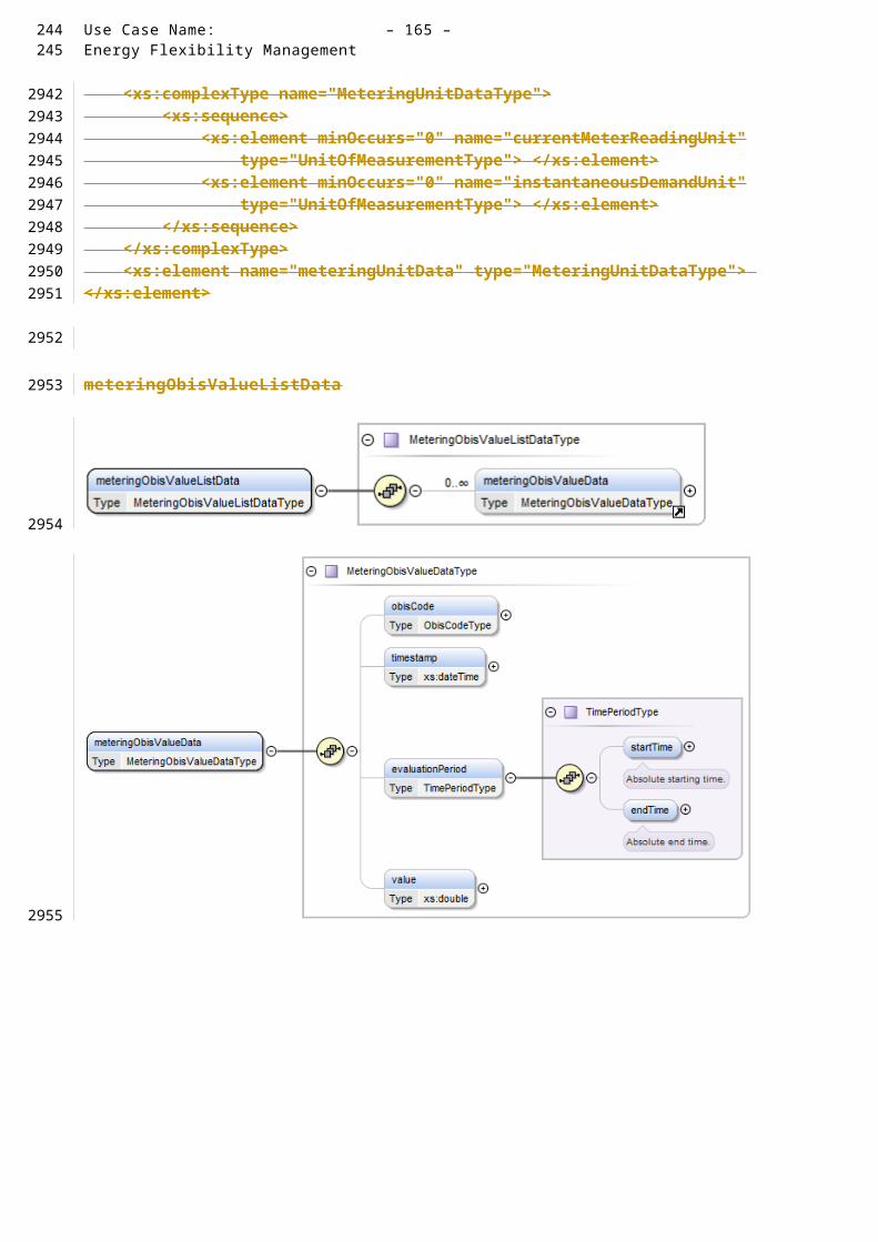
Use Case Name: – 165 –Energy Flexibility Management
A.2.3 The grid recognizes (severe) stability issues
The grid sends a load control message, requesting the CEM to adjust the load (by either increasing or decreasing consumption or generation). The load control message may include
an incentive value and/or time frame for answering to the request
an incentive value and/or time frame for acting on the request
Depending on user configurations, several options are possible, e.g.:
The user allows the Customer Energy Manager to adjust the load of some of his devices (e.g. of the freezer for a defined/maximum time). The support of these capabilities may usually be part of a contract between Energy Supplier and customer. After receiving the request from the grid, the CEM checks the status of attached Smart Devices checking on the possibility of e.g. reducing consumption by xW, x% of consumption or alternatives which leads into a change in consumption / generation The Smart Device may react so and may respond with the achieved details
The CEM may send the response back to the grid. The CEM checks the status and may recalculate (e.g. postpone) the starting time of already planned upcoming cycles ( see x.x.x, y.y.y ) The CEM updates starting time o f Smart Devices
CEM feeds own battery pack energy into own network or into the grid The CEM checks s tatus of battery pack In case t he battery pack can provide enough energy the CEM can decide to start feeding process
CEM stores additional energy from the grid into own battery pack The CEM checks status of battery pack In case the battery pack has enough capacity and if the energy price plus the incentive value is better than the average cost of stored energy, the CEM starts feeding process
To be updated: is this a real user story
232233
2944
29452946
2947
2948
2949
2950295129522953295429552956
2957295829592960
2961296229632964
2965296629672968
2969

– 166 – publication no./stage(CDV,FDIS...) IEC:201X
A.2.4 Limitation to fixed amount of power power - The user wants to limit his consumption to his own local production (e.g. PV)
The user instructs the CEM to limit power consumption up to amount of own decentralized power. Along with this command, several additional parameters may be set, for example:
At which time of the day this limit applies
Which devices are exempt from this limit
…
The CEM is kept informed on total power consumption and generation through the smart meter.
When managing power consumption in the house, the CEM takes into account the above limits and parameters.
If the user wants to start a smart device, then the CEM is notified by the smart device and receives, amongst others, a load profile (see 3.1.1).
If, when based on the load profile and other parameters, the CEM concludes that the power limit will be exceeded, then it may send a warning message to the relevant device and to a display if one is available.
Based on the warning message, the user may decide to postpone his consumption or to manually overrule the power limit.
Furthermore there is the possibility that premises go in isolated (island) operation from the distribution system. Such premises will be isolated or "switch of" by the network operator or by premises own control facilities based on appropriate monitoring arrangements. The ability of island operation comes from the fact that they are able to cover their own power demand by premises own "distributed" generator and/or storage facilities, i.e. batteries. In such situations the distribution network can be in operation or out of service due to emergency situations and/or planned maintenance and/or repair activities. Premises with their own generation and storage facilities can cover their total demand or at least part of their total demand controlled by a Customer Energy Management system with or without being connected to the distribution network. In normal situations surplus of energy generated by the premises can be delivered back to the distribution system. Reconnecting the premises to the distribution system after a period of island operation has to be arranged in a safe and coordinated manner. That can be arranged by a synchronizing facility/unit with build-in monitoring and control arrangements; the latter can be part of the fore-mentioned CEM.
1.4.1 CEM manages Simple Devices
1.4.1.1 Switch on/off simple devices, dim simple devices
Examples are turning on/off simple devices such as lighting, smart plugs and dimming lighting etc.
234
29702971
29722973
2974
2975
2976
2977
29782979
29802981
298229832984
29852986
29872988298929902991299229932994299529962997299829993000
3001
3002
3003

Use Case Name: – 167 –Energy Flexibility Management
A.2.5 The Customer wants to sell his flexibility to the grid
Based on information on:
Current consumption (received from smart meter)
Currently running devices and their load profiles
Device assignments to be ran and their load profile
Tariff information
Information on power limitations
the CEM may identify opportunities for flexibility.
The user may have set constraints on the flexibility that may be offered to the grid. These constraints may be:
Which loads (or generators) and user specified conditions are available for providing flexibility
Start time of the flexibility (start time within a certain time period)
Duration of the flexibility
Amount of flexible power at a point in time
Amount of flexible energy
The CEM proposed this flexibility to the grid, by providing the following information:
Start time of the flexibility (start time within a certain time period)
Duration of the flexibility
Amount of flexible power at a point in time
Amount of flexible energy
These offerings are negotiated by a process of offering, accepting or rejecting, possibly. Reasons for accepting and rejecting include suitability of the offered flexibility (the expected value of the flexibility in e.g. a portfolio) and financial aspects.
If the grid wants to accept the offer, it sends a message indicating this and with the incentive that is related to the acceptance (this is the Flexibility Offer Acceptance)
A second message from the grid indicates how the flexibility should be allocated. This message comes in the form of a load profile, but stays within the constraints of the flexibility offer.
The CEM implements the flexibility allocation by adjusting the (time of the) consumption / generation of devices on the premise.
235236
3004
3005
3006
3007
3008
3009
3010
3011
30123013
3014
3015
3016
3017
3018
3019
3020
3021
3022
3023
302430253026
30273028
30293030
30313032

– 168 – publication no./stage(CDV,FDIS...) IEC:201X
A.2.6 The Customer wants to sell own decentralized energy (e.g. PV) to Smart Grid
When the consumer wants to sell his own decentralized energy to the grid, several options are possible:
Based on a price message or load/generation control message, CEM may instruct local generators / storage to adjust output (…...).
CEM offers to sell an amount of energy at a specified price, this corresponds to offering flexibility as described under…...
CEM releases stored energy (see …...)
Update necessary
EDITOR NOTE: NEED TO CONSIDER/CHECK COMBINING THESE WITH THE APPROPRIATE JAPANESE USER STORIES
A.2.7 Grid related Emergency Situations (Blackout prevention)
The grid is close to a black-out and will soon have to cut off sections of the grid.
As a means of preventing this by limiting the overall energy consumption to a certain minimum, the grid sends an emergency message to all connected households in order to instruct them to place their connected devices into “emergency connected off mode”.
Assumption: The CEM and smart devices are pre-configured with an “emergency connected off mode” profile. This profile defines which connected devices enter “emergency connected off mode” and what that mode entails (on a device by device basis). This profile is agreed by both the consumer and the energy provider and is likely to be included in a contract.
The CEM receives an emergency message (some low consumption, essential devices like gas boilers that require a minimum of electricity to run, may be allowed to stay operational – this will be defined within the profile).
This message may include the duration of the emergency period.
The CEM sends a message to all connected smart devices to switch to “emergency connected off mode”.
The devices switch to “emergency connected off mode”.
When the emergency period has ended (either because the predetermined emergency time has passed or because the grid sent a message that the emergency has passed), the CEM instructs the devices that they may resume operations as normal.
A.2.8 The customer wants to connect a new smart device to the CEM
Installer and/or “plug and play” consumer installation will be supported
Discovery, authentication etc. are handled by lower layers and are out of scope of this document
237
3033
30343035
30363037
30383039
3040
3041
30423043
3044
3045
3046
304730483049
3050305130523053
305430553056
3057
30583059
3060
306130623063
3064
3065
3066
3067

Use Case Name: – 169 –Energy Flexibility Management
Communication messages and data used between the CEM and Device concerning the capability (type and functionality) of the device are within the scope of this document
A.2.9 A smart device disconnects unexpectedly (failure)
The CEM and smart device exchange regular messages or status messages to keep each other informed of their connection (to the network) and of their operational status.
At a moment in time, the CEM does not receive such a message from a device when it expected one.
The CEM sends a status request to the device.
In case the CEM does not receive a response or when the device responds with an abnormal status, the CEM sends a warning message to an advanced display. The CEM may also send a warning to a third party (e.g. service provider) on the grid side.
A.2.10 The consumer wants to be informed on their historic and forecasted energy use
The consumer indicates on the CEM User Interface that they want information on their historic and forecasted energy use.
In case the CEM does not have the relevant historic information, it may request this data from the smart meter or other source.
Based on the information related to currently connected devices and their expected consumption and generation and based on the historic data, the CEM may build a short term energy forecast and informs the user.
A.2.11 The consumer wants to know an estimate of the yearly energy cost of a smart device
(This user story assumes that the CEM or the device stores information on time-of-use consumption of individual devices and that the CEM has a historic record of time-of-use buckets and their related tariffs in the relevant currency).
The consumer indicates on the CEM User Interface that they want information on the yearly cost of a specific device.
The CEM collects information of individual device’s consumption from its memory or requests this information from the device.
The CEM collects information related to historic time-of-use buckets and tariff information expressed in financial units from its memory.
The CEM combines (estimated) consumption information with tariff information and sends the response to the consumer’s query back to the CEM User Interface.
A.2.12 The consumer wants a storage device to feed energy to the grid once the tariff reaches a certain threshold
The consumer parameterizes the CEM to feed energy once the tariff for selling energy reaches a certain threshold. Additionally, the consumer may parameterize that local storage should not drop below a certain point
The CEM receives a new tariff from the grid (may be via the smart meter) and notices that this tariff exceeds the abovementioned threshold.
The CEM may check:
238239
30683069
3070
30713072
30733074
3075
307630773078
3079
30803081
30823083
308430853086
30873088
308930903091
30923093
30943095
30963097
30983099
31003101
310231033104
31053106
3107

– 170 – publication no./stage(CDV,FDIS...) IEC:201X
Whether the amount of stored energy is not below a user specified point
Whether releasing stored energy to the grid would be inconsistent with other user commands / settings (e.g. electric vehicle that must be charged by a specific time, flexibility assignments, load control messages requesting to increase consumption or lower generation, etc…)
When there is no conflict with the abovementioned points, the CEM instructs the storage device to feed energy in the grid.
A.2.13 Manage energy consumption of smart devices by Smart Grid
This user story explains how on July 15th, a premises customer allows the supplier (or energy service provider) to raise the temperature setting of his air-conditioner in a defined range so as to curtail power demand for a specific time.
On the 14 th of July, the supplier requests a reduction of power consumption by tomorrow, July 15, from 10:00 am to 2:00pm.
The customer finds the request and confirms that he is willing to comply by e.g.
Setting the temperature range to a specific one.
Turning on the air-conditioner
In the morning of July 15, the supplier analyzes the power consumption data continuously delivered through data collectors which accumulate the power consumed by all customers via smart meters, and reconfirms the high demand forecast during the peak period considering the metrological data sent from the weather forecast system.
At 11:00am, given the estimated power demand for the coming hours, the supplier sends messages to the CEM and asks for the possibility to reduce power consumption by 300 W (Power I) from 12:00 am to 2:00 pm.
The CEM informs the air-conditioner about the target of reduction including timeframe.
At 12:00 am the air-conditioner reduces power consumption and communicates this to the CEM. If the requested settings cannot be reached, the air conditioner informs what can be achieved.
240
3108
310931103111
31123113
3114
311531163117
31183119
3120
3121
3122
3123312431253126
312731283129
3130
31313132

Use Case Name: – 171 –Energy Flexibility Management
A.2.14 Manage in- premises Battery System
This user story explains how a battery owned by premises customers charges (buys) electricity during off-peak period, from 11:00 pm to 5:00 am, and discharges power to use appliances in the house during peak period, 10:00 am to 2:00 pm.
The customer prepares the setting of the battery through the CEM:
o Prioritizing the reduction of electricity cost by charging cheaper electricity at off-peak time and discharging power during the peak-period.
The CEM calculates the operation plan based on:
o Tariff information, for example;
XX.XX cent/kWh, cheaper electricity, from 11:00 pm to 5:00 am
XX.XX cent/kWh, expensive, from 10:00 am to 2:00 pm.
o Expected power consumption based on;
The past power consumption records;
The owner’s today’s schedule
o The remaining battery charge
Based on this operation plan, the CEM instructs the battery to charge and discharge in the most optimal way.
A.2.15 Manage Distributed Energy Resources (DER)
Alternative 1: this user story describes how a DER owned by a premises customer generates electricity in peak periods, from 10:00 am to 2:00 pm, to reduce electricity cost.
The customer prepares the setting of the DER through the CEM:
o Select the plan that utilizes DER to generate electricity during peak period in a day.
The CEM checks the status of the DER.
The CEM starts the DER at 10:00 am and stop it at 2:00 pm.
Alternative 2: this user story describes how a DER owned by a premises customer generates electricity when a dynamic pricing message is provided from the supplier to the customer.
The customer prepares the setting of the DER through the CEM:
o Select the plan, which initiates the DER operation when a tariff of XX.XX cent/kWh or more of electricity price is offered.
The CEM checks the messages from the supplier and status of the DER.
At 10:30am, the supplier offers XX.XX cent/kWh from 11:00 am to 2:00pm.
The CEM receives the message and compares the price with the set value.
The CEM starts the DER if both that the price is equal to or higher than the set value and that the DER is ready are confirmed.
The DER generates electricity from 11:00 am to 2:00 pm.
If after 2:00 pm the tariff no longer exceeds the abovementioned threshold, the CEM instructs the DER to stop generation.
241242
3133
313431353136
3137
31383139
3140
3141
3142
3143
3144
3145
3146
3147
31483149
3150
3151
31523153
3154
3155
3156
3157
3158
31593160
3161
31623163
3164
3165
3166
31673168
3169
31703171

– 172 – publication no./stage(CDV,FDIS...) IEC:201X
A.2.16 Peak Shift Contribution by Battery Aggregation
The customer likes to participate in the Peak Shift Contribution of Battery Aggregation (PSCBA) according to the conditions such as the maximum and minimum value of Customer’s Battery output power that are specified by the customer. Under the contract between the electric company and the customer, battery SCADA and the CEM communicate with each other.
The customer lets CEM participate in the PSCBA.
Battery SCADA sends “request for Schedule” to the CEM.
The CEM sends the requested schedule to Battery SCADA. This includes Detail Schedule/ Outline Schedule/ Surplus Schedule of Customer’s Battery.
Battery SCADA calculates the total surplus potential and the schedule of batteries.
According to the plan for PSCBA set by Gird Operator, Battery SCADA calculates the schedule of each battery for the plan.
Battery SCADA sends “inquiry” command to CEM. This includes the plan for PSCBA corresponding to Customer’s Battery.
CEM sends the response of “inquiry” message to Battery SCADA. This includes “inquiry rejection” or “inquiry acceptance”
In case of “inquiry acceptance”, Battery SCADA sends “execution notification” to CEM.
CEM sends charging/discharging command to Customer’s Battery according to the Customer’s detail schedule and the plan for PSCBA corresponding to Customer’s Battery.
A.2.17 Control of Smart home appliances based on price information by time slot
The user likes to use a water heater, air conditioner and other appliances such that total electricity charges are relatively less.
The user instructs the CEM to program the water heater, air conditioner and other appliances following a number of conditions.
The user inputs operating conditions of each appliance at CEM, e.g.:
o Water heater temperature 90C, water level 50%
o Air conditioner mode: cooling down, wind: auto, temperature: 27C
The user inputs time conditions (desirable start time, desirable finish time) of each appliance at CEM, e.g.:
o Water heater finish by AM7
o Air conditioner finish cooling down by AM10
The electricity tariff information is issued at noon every day for the following 24 hours.
Based on the input conditions, time conditions and tariff, the user lets CEM calculate a program for the following day such that total electricity charges are relatively less
CEM calculates an operating plan for those appliances considering operation time, power consumption during operation, electricity charges and so forth
The user confirms the calculation results and commits the operating plan to be executed
o CEM controls each appliance as programmed according to conditions of operating plan
243
3172
3173317431753176
3177
3178
31793180
3181
31823183
31843185
31863187
3188
31893190
3191
31923193
31943195
3196
3197
3198
31993200
3201
3202
3203
32043205
32063207
3208
32093210

Use Case Name: – 173 –Energy Flexibility Management
A.2.18 Control of Smart home appliances in response to power saving request from Electric power supplier
The user likes to use a Water heater, Air conditioner and other appliances such that power saving request from electric power supplier is satisfied if possible.
The user instructs the CEM to program the water heater, air conditioner and other appliances following a number of conditions.
The user inputs operating conditions of each appliance at CEM, e.g.:
o Water heater temperature 90C, water level 50%
o Air conditioner mode: cooling down, wind: auto, temperature: 27C
The user inputs time conditions (desirable start time, desirable finish time) of each appliance at CEM, e.g.:
o Water heater finish by AM7
o Air conditioner finish cooling down by AM10
At AM7, the CEM receives a request for power saving from PM1 to PM5.
The user lets CEM calculate a program at AM8 with input conditions such that power saving request is satisfied as possible
CEM calculates to program an operating plan for those appliances before, during and after the requested power saving, considering operation time, power consumption while in operation, electricity charges and so forth
The user confirms calculation results and commits the operating plan to be executed
The user activates the execution of operating plan at CEM
o CEM controls each appliance as programmed according to conditions of operating plan
A.2.19 Control of Smart home appliance before power cut
The user likes to use a Water heater, Air conditioner and other appliances before power cut takes place
The user instructs the CEM to program the water heater, air conditioner and other appliances following a number of conditions.
The user inputs operating conditions of each appliance at CEM, e.g.:
o Water heater temperature 90C, water level 50%
o Air conditioner mode: cooling down, wind: auto, temperature: 27C
The user inputs time conditions (desirable start time, desirable finish time) of each appliance at CEM, e.g.:
o Water heater finish by AM7
o Air conditioner finish cooling down by AM10
The information is issued at AM7 that a power cut will occur from PM1 to PM5.
The user lets CEM calculate a program at AM8 with input conditions considering power cut informed by electric power supplier
CEM calculates to program an operating plan for those appliances before, during and after the scheduled power cut, considering operation time, power consumption while in operation and so forth
The user confirms calculation results and commits the operating plan to be executed
The user activates the execution of operating plan at CEM
o CEM controls each appliance as programmed according to conditions of operating plan
244245
32113212
32133214
32153216
3217
3218
3219
32203221
3222
3223
3224
32253226
322732283229
3230
3231
32323233
3234
32353236
32373238
3239
3240
3241
32423243
3244
3245
3246
32473248
324932503251
3252
3253
32543255

– 174 – publication no./stage(CDV,FDIS...) IEC:201X
A.2.20 Control of Smart home Appliances in case of natural disaster
The user likes to use a Water heater and Storage battery at the highest priority in case that unstable electric power supply and/or power cut is expected due to natural disaster
The user presets Water heater and storage battery at CEM to program an emergency operation plan
The user inputs operating conditions of each appliance at CEM
o Water heater temperature 90C, water level: 50%
o Storage battery mode: quick charge
The user lets CEM calculates a program with input conditions in case CEM receives power alert from electric power supplier
CE¨M calculates an operating plan for Water heater, Storage battery and all other appliances when CEM receives power alert. Such an operating plan could look like the following:
o confirm the operating status of all appliances connected to CEM
o execute normal shutdown process to all appliances in operation except Water heater and Storage battery
o execute operation of Water heater and Storage battery with conditions set by the user
The user inputs auto-execution of emergency operating plan as programmed at CEM in case CEM receives power alert from electric power supplier
CEM receives power alert from electric power supplier at AM10
CEM commences at AM10 + n to control each appliance as programmed according to conditions of operating plan, an example of which is:
o continue operating Water heater and Storage battery and execute normal shutdown process to finish as far as CEM does not receive a message to call off power alert;
o execute normal shutdown process of Water heater to finish, and continue operating Storage battery in case that CEM receives power saving request;
o continue operating Water heater and Storage battery till start time of power cut and execute normal shutdown process to finish operating before start time of power cut in case that CEM receives power cut information;
o execute normal shutdown process to Water heater and Storage battery to finish in case that CEM receives a message to call off power alert
246
3256
32573258
32593260
3261
3262
3263
32643265
32663267
3268
32693270
32713272
32733274
3275
32763277
32783279
32803281
328232833284
32853286

Use Case Name: – 175 –Energy Flexibility Management
A.2.21 Bilateral Demand Response (N egawatt Transaction= Japanese related requirement)
This user story describes how an energy supplier asks for a demand responsive load from consumer on the day when tightness of electricity supply and demand is expected.
On the day before the event day (at which a supply tightness is expected), the energy supplier indicates a specification of demand reduction, requesting flexibility from the connected consumers / CEMs. The specification/flexibility request contains:
o The date,
o Time window (event start and event end),
o Amount in control area.
Based on information on forecasted energy use and user settings, the CEM proposed flexibility as described under Error: Reference source not found . The consumer can also input this information manually. The resulting bid contains:
o Amount of demand responsive load (kW) and
o Bidding price (price/kWh).
The energy supplier ranks bids from consumers according to “merit order” and notifies execution results.
Consumers, who made a successful bid, reduce their load in the time window on the specified day..
247248
3287
32883289
329032913292
3293
3294
3295
329632973298
3299
3300
33013302
33033304

– 176 – publication no./stage(CDV,FDIS...) IEC:201X
A.3 Use Case mapping (User Stories – Use Cases)
Insert Table
Use cases indicated in BLACK are directly contributing towards the fulfillment of the user story
Use cases indidated in GREY are supporting the user story
Use cases indicated with "GAP" still have to be developed
249
3305
3306
3307
3308
3309
3310
3311
3312
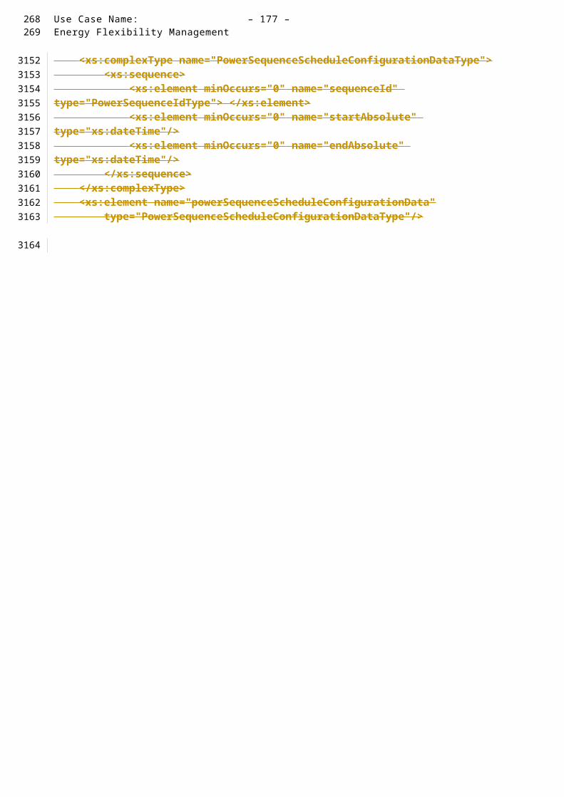
Use Case Name: – 177 –Energy Flexibility Management
A.4 Use Case descriptions
A.4.1[A.2.1] Introduction
The following use cases are based on the above user stories and the architecture defined earlier in this Technical Report. Note that the use cases only describe communication between Actor A/B, the CEM, the smart meter and the smart devices. For sake of simplicity, these use cases do not represent the energy management gateway and the smart metering gateway - when developing the use cases we assumed that the gateways do not provide functionalities contributing towards the goals of the use cases. In reality, the gateway may provide functionality in terms of routing information, translation of protocols, device management, security and service capabilities .
Note that several use case scenarios may work together in an iterative way. E.g. there might be a negotiation which uses the price (WGSP2112) to get a forecast (WGSP2111), then adapting the price, which might be binding from there on.
Also note that information can be transferred via different channels to actor A, B and to the consumer or in-home devices. This implies that the use case could effectively be split up into several sub-use cases, each with its own goal.
For the definition of the use cases in this document, the already referenced SGCG architecture model has been used as a basis.
Note that the actors in the above architecture are functional entities, which means that some of them may be part of the same physical device (e.g. CEM functionality may be part of a smart device, the smart meter might also encompass the smart metering gateway and CEM, etc…)
CEM Smart Device*
Simple external consumer
display
Actor AEnergy
management gateway (EMG)
Smart Metering gateway (LNAP )
Smart meter functionalityActor B
Energy Management / Providing Flexibility (M490)
M441 architecture
Market communication
* e.g. HBES device, smart appliances, storage, generator, domestic charger for EV, complex display
Smart Grid Connection
Point
Functional metering reference architecture according the SM-CG (TR50572)
250251
3313
3314
33153316331733183319332033213322332333243325
33263327
33283329
3330
33313332
3333
333433353336
3337

– 178 – publication no./stage(CDV,FDIS...) IEC:201X
A.4.2 JWG1100-HLUC Flexible start of a Smart Device (SD)
A.4.2.1 Description of the Use Case
Name of Use Case
Use Case IdentificationID Domain(s)/
Zone(s)Name of Use Case
JWG1100
Domain: Customer Premises, DER
Zones:Process, Field, Station
SD consumes / generates energy on a flexible basis (High Level Use Case or Generic Use Case)
Version Management
Version ManagementChanges / Version
Date Name Author(s) or Committee
Domain Expert
Area of Expertise / Domain / Role
Title/Changes Approval Statusdraft, for comments, for voting, f inal
0.1 Nov.04, 2013
Stephan Fertig (CLC TC59x WG7)
Editor Initial Draft Draft
0.2 Dec.06, 201
Stephan Fertig (CLC TC59x WG7)
Editor Updated Version after CLC TC59x discussions
Draft
0.3 Jan.06, 2014
Stephan Fertig (CLC TC59x WG7)
Editor Update HLUC to fit Joint Use Case Workshop description
Draft
0.4 Mar 07, 2014
Stephan Fertig (CLC TC59x WG7)
Editor Added JWG-ID Draft
252
33383339
3340
3341
3342
3343
3344
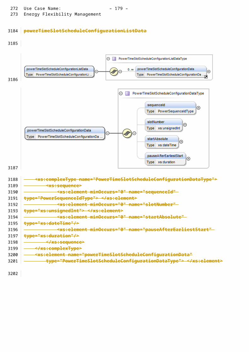
Use Case Name: – 179 –Energy Flexibility Management
Scope and Objectives of Use Case
Scope and Objectives of Use Case
Scope In some cases Smart Devices provide flexibility towards their time. The device can manage its flexible running times by itself and communicates them to the CEM on a negotiation basis.
Utilizing flexibility by a CEM must be negotiated and confirmed with the smart device. The flexible operation of a Smart Device does not imply a specific optimization strategy. It depends on the control algorithm which the customer defines for its Smart Device and the CEM.
The scope of that High Level Use Case deals with the basic information exchange between a Smart Device and the CEM to allow a flexible start. Also it covers the information exchange on the energy consumption during operation to allow an energy scheduling within the CEM.
Objective(s) This use case defines the basic information which is required to offer flexible start of Smart Devices.
There are various optimization targets possible for setting a flexible start time.
Related business case(s)
- Demand Response (DR)
- Demand Side Management (DSM)
Narrative of Use Case
Narrative of Use CaseShort descriptionThe User activates a specific profile on the Smart Device that allows a flexible start. The Smart Device then starts a negotiation process with the CEM to find the most suitable start time. The interaction between the SD and the CEM does not require user interaction and operates autonomously. The SD fulfils the job according to the activated profile and might ask the user for final confirmation. After job completion the end customer might get notified on successful or failed commissioning.
A Smart Device might have two basic operational modes:
- Power Consumption by using electricty
- Power Producing by generating electricity
Complete descriptionThe User activates a specific action profile on the Smart Device. The Smart Device then negotiates a start time with the CEM based on the selected specifification. Such specification might include user specific requirements like pre-defined end-time, maximum energy consumption, or something else and device specific capabilities. Such a profile can be very simple and defines a setting for a specific purpose.
The interaction between the SD and the CEM does not require user interaction and operates autonomously. It is up to the SD to find the best possible solution according to the user defined operational mode. The SD visualizes relevant information to the User if possible and starts action in cooperation with the CEM. Once the User activates a profile on flexible start time of a smart device, the User hands over the control to the CEM or Smart Device.
The SD fulfils the job according to the activated profile of the user and notifies the User on successful or failed commissioning. A notification and visualization method of relevant information varies on the appliances that are used.
This Use Case comprises three primary use cases:
1. JWG1101 : SD informs CEM about flexible start
The Smart Device informs the CEM about its flexibility and limitations.
253254
3345
3346
3347

– 180 – publication no./stage(CDV,FDIS...) IEC:201X
2. JWG1102 : CEM informs SD about starting time
The CEM coordinates an optimized starting according to the selected operational strategy. It might require consideration of more than one smart device for calculating a suitable start time.
3. JWG 1103 : CEM informs SD about slot shift
The calculated start which had been sent to the Smart Device by the CEM requires an update. There might be a change in the environment which requires the CEM to recalculate a new start time (within the pre-defined limits of the affected Smart Devices).
General Remarks
General RemarksThis High Level Use Case or Generic Use Case considers smart devices like home appliances (white goods, brown goods and consumer electronics).
Any communication between SD and CEM must provide acknowledge handling on application level and basic failure detection. A broken communication link shall not lead to an unsecure and critical situation. Therefore, Smart Devices must provide device specific fail-safe mechanisms to prevent danger from the customer (e.g. a cleaning process of an oven with very high temperatures shall not lead to a critical situation in the home if communication fails).
A.4.2.2 Diagrams of Use CaseDiagram of Use Case
See detailed description of use cases
255
3348
3349
3350
3351
3352

Use Case Name: – 181 –Energy Flexibility Management
A.4.2.3 Technical Details
Actors: People, Systems, Applications, Databases, the Power System, and Other Stakeholders
For the definition of this use case, the following architecture has been used as a basis.
Note that the actors in the above architecture are functional entities, which means that some of them may be part of the same physical device (e.g. CEM functionality may be part of a smart device, the smart meter might also encompass the smart metering gateway and CEM, etc…).
Please consider that the scope of this high level use does not require all actors shown on the figure above. Following table shows involved actors.
ActorsGrouping (Community) Group Description Actor Namesee Actor List
Actor Type see Actor List
Actor Description see Actor List
Further information specific to this Use Case
Customer Energy Manager
InternalThe CEM is a logical function optimising energy consumption and or production based on messages received from the grid, consumer’s settings and contracts, and devices minimum performance standards. The Customer Energy Manager collects messages sent to and received from connected devices; especially the in-home/building sector has to be mentioned. It can handle general or dedicated load and generation management commands and then forwards these to the connected devices. It provides vice versa information towards the “grid / market”. Note that multiple loads/generation resources can be combined in the CEM to be mutually controlled.
When the CEM is integrated with communication functionalities it is called a Customer Energy Management System or CEMS
Smart deviceExternal
A smart device may be an appliance, generator or storage device (Local storage devices include direct and functional electricity storages such as electrochemical batteries, heat pumps and micro CHP such as fuel cells with heat buffers,
CEM Smart Device*
Simple external consumer
display
Actor AEnergy
management gateway (EMG)
Smart Metering gateway (LNAP )
Smart meter functionalityActor B
Energy Management / Providing Flexibility (M490)
M441 architecture
Market communication
* e.g. HBES device, smart appliances, storage, generator, domestic charger for EV, complex display
Smart Grid Connection
Point
Functional metering reference architecture according the SM-CG (TR50572)
256257
3353
33543355
3356
3357
3358335933603361336233633364

– 182 – publication no./stage(CDV,FDIS...) IEC:201X
air conditioning and cooling devices with thermal inertia, etc…) . The smart device can receive data directly from the grid, though an interface with the CEM and can react to commands and messages from the grid in an intelligent way.
Since the smart device is outside the scope of the SGCG, it must be seen as an external actor
Smart appliance (white goods)
ExternalAn example of a smart device is a smart white goods appliance which is an appliance that has the capability to act in response to a message from the grid and thereby optimize its behaviour towards the energy supply network. The message can be received from a utility or a third party energy service provider directly or via a home energy management system,
The message can be information like the cost of energy or the amount of available renewable energy, or it can be a Demand Respond message (delay load message or other related information) that the appliance must receive, interpret and react upon based on pre-set or active consumer input. The smart appliance is not guaranteed to respond, but will do so based on its status and user settings in order to ensure the expected performance.
The consumer has the ultimate control of the appliance and can override any specific mode (e.g. override a delay to allow immediate operation, limit delays to no more than a certain number of hours, or maintain a set room temperature).
Any appliance operation settings or modes shall be easy for an average, non-technical consumer to activate or implement.
Actor AExternal
External actor (Smart Grid Market Role) interacting with the system functions and components in the home or home automation network through the energy management communication channel.. Examples of such market roles are the Energy Provider, the Energy Services Provider, the aggregator, etc…
Actor BExternal
External actor (Smart Grid Market Role) interacting with the system functions and components in the home or home automation network through the metering communication channel. This actor is responsible for collecting metering data. Examples of such market roles are the DSO, metering company, etc.
UserExternal
The end customer who has acquired a smart device. The end customer is responsible for configuring and setting operation mode of the Smart Device.
258
3365

Use Case Name: – 183 –Energy Flexibility Management
Triggering Event, Preconditions, Assumptions
Use Case ConditionsActor/System/Information/Contract
Triggering Event Pre-conditions Assumption
SD
Activation Message SD is active and operational.
User has created or selected a profile before creating the event. SD starts negotiations with CEM based on the profile.
References
ReferencesNo. Referenc
es TypeReference Status Impact on
Use CaseOriginator / Organisation Link
1 Guideline Basic definitions and common procedures
Final Terms and definitions
SG-CG Sustainable Processes WG
ftp://ftp.cen.eu/EN/EuropeanStandardization/HotTopics/SmartGrids/Sustainable Processes.pdf
2 Technical Report
User Story and Sequence diagrams
Draft Major impact on Scenario
IEC TC57 / CLC TC205 / CLC /TC59x
-
3 Standard Use Case Template
Draft (FDIS)
Template desctription
IEC TC8 -
Further Information to the Use Case for Classification / Mapping
Classification InformationRelation to Other Use Cases Level of Depth
High Level Use Case
Prioritisation Generic, Regional or National Relation
Generic High Level Use Case which can be applied to any kind of Smart Device.
Viewpoint
This High Level Use Case has the User perspective and the interaction of the SD with an overall energy management system. It does not consider market mechanisms for flexibility offering or power grid specific implementations.
Further Keywords for Classification
Generic High Level Use Case
259260
3366
3367
3368
3369
3370
3371

– 184 – publication no./stage(CDV,FDIS...) IEC:201X
A.4.2.4 Step by Step Analysis of Use Case
Steps – Scenario Name
Scenario ConditionsNo. Scenario
NamePrimary Actor Triggering Event Pre-Condition Post-Condition
Steps – Scenarios
Scenario JWG1100 Flexible Start SDScenario Name :
No. 1 - Flexible start time of appliance
Step No.
Event Name of Process/ Activity
Description of Process/ Activity
Service Information Producer (Actor)
Information Receiver (Actor)
Information Requirements , R-ID Exchanged
1 - Preparation User prepares SD for operation.
Preparation
User SD Device Specific (Door Closed, Water tap connected, Gas burner connected, electrical heating connected, …)
2 - Operation mode preparation
User enters settings for operational mode
Profile Generation/Selection
User SD Device and Customer Specific Data
3 Activation Message
Operation Mode Activation
Pre-defined or manually entered setting become active on SD
Service Activation
User SD General Device Data (Activation)
4 SD Notification
SD informs CEM
SD sends activation profile to CEM.
Notification of User request to CEM
SD CEM Profile
5 Negotiation
CEM/SD Negotiation
CEM and SD negotiate on flexible start time
Schedule Planning
SD/CEM CEM/SD Device and Customer Specific Data
6 User Information
Visualization
SD notifies the User on the schedule
Information delivery
SD User Profile
261
3372
3373
3374
3375
3376

Use Case Name: – 185 –Energy Flexibility Management
A.4.2.5 Information ExchangedInformation Exchanged
Name of Information (ID)
Description of Information Exchanged Requirements to information data
Device Specific Data (DSD)
Device specific data can be classified to each product family like dish washer, washing machine, heating unit, etc.
This set of data is specific to the category of the SD. A SD might have multiple device specific data sets when combining multiple features.
Such information is sensitive in a way that any modification might change certain behaviour of a SD. That is crucial for CEM-SD negotiations.
Therefore, the communication must be protected from misuse and external influences.
Customer Specific Data (CSD)
The user who operates might be able to create a profile for customer specific information. Depending on the SD the data set might contain SLAs with energy providers, comfort settings, Customer habits, etc.
A SD can maintain one or more customer specific data sets.
CSD contains sensitive information. Such a data set might contain SLAs and privacy relevant information. Therefore, such information must be handled with care and shall be accessible to relevant actors only. That includes, that the CEM shall not be able to access contract specific information which belong to third party service providers.
General Device Data (GDD)
Common information which is required from each SD like an ID, communication address, status information, etc.
This set of data is not specific to white, brown, or consumer goods.
GDD provide common standardized functionalities which are the lower limit for enabling
Such information is sensitive in a way that any modification might turn on or off a SD.
Therefore, the communication must be protected from misuse and external influences.
Energy Profile An energy profile defines characteristics towards s specific operational mode which is applicable to the Smart Device.
Such information can be used for power consumption but also power generation.
The energy profile does not contain sensitive data in a way that it gives indication on the used Energy for a specific operational mode.
A.4.2.6 Requirements (optional)
262263
3377
3378
3379

– 186 – publication no./stage(CDV,FDIS...) IEC:201X
A.4.2.7 Common Terms and DefinitionsCommon Terms and Definitions
Term Definition
Energy Profile An energy profile defines the power consumption/generation over time. The power might vary on the smart device which will be captured and visualized by the energy profile.
An energy profile might be split into multiple time slots. Such time slots have a fix amount of power to get a discrete power consumption/generation profile. A simple energy profile will contain only one power value and its duration.
A.4.2.8 Custom Information (optional)Custom Information (optional)
Key Value Refers to Section
264
3380
3381
3382

Use Case Name: – 187 –Energy Flexibility Management
A.4.3 SPECIFIC USE CASE (JWG1101) SD informs CEM about flexible start
A.4.3.1 Description of the Use Case
Name of Use Case
Use Case IdentificationID Domain(s)/
Zone(s)Name of Use Case
JWG1101
Domain: Customer Premises, DER
Zones:Process, Field, Station
SD informs CEM about flexible start (Specific Use Case or Primary Use Case)
Version Management
Version ManagementChanges / Version
Date Name Author(s) or Committee
Domain Expert
Area of Expertise / Domain / Role
Title/Changes Approval Statusdraft, for comments, for voting, f inal
0.1 Jan.06, 2014
Stephan Fertig (CLC TC59x WG7)
Editor Initial Draft Draft
0.2 Mar 07, 2014
Stephan Fertig (CLC TC59x WG7)
Editor Added Use Case ID
Draft
Scope and Objectives of Use Case
Scope and Objectives of Use Case
Scope After a Smart Device was able to register at the CEM and works properly, it informs the CEM about its flexible start time.
Objective(s) This use case defines the basic information which is required to inform the CEM on a flexible start time.
Related business case(s)
- Demand Response (DR)
- Demand Side Management (DSM)
Narrative of Use Case
Narrative of Use CaseShort description
Complete description
265266
33833384
3385
3386
3387
3388
3389
3390
3391
3392

– 188 – publication no./stage(CDV,FDIS...) IEC:201X
General Remarks
General Remarks
A.4.3.2 Diagrams of Use CaseDiagram of Use Case
267
3393
3394
3395
3396
3397

Use Case Name: – 189 –Energy Flexibility Management
A.4.3.3 Technical Details
Actors: People, Systems, Applications, Databases, the Power System, and Other Stakeholders
For the definition of this use case, the following architecture has been used as a basis.
Note that the actors in the above architecture are functional entities, which means that some of them may be part of the same physical device (e.g. CEM functionality may be part of a smart device, the smart meter might also encompass the smart metering gateway and CEM, etc…).
Please consider that the scope of this high level use does not require all actors shown on the figure above. Following table shows involved actors.
ActorsGrouping (Community) Group Description Actor Namesee Actor List
Actor Type see Actor List
Actor Description see Actor List
Further information specific to this Use Case
Customer Energy Manager
InternalThe CEM is a logical function optimising energy consumption and or production based on messages received from the grid, consumer’s settings and contracts, and devices minimum performance standards. The Customer Energy Manager collects messages sent to and received from connected devices; especially the in-home/building sector has to be mentioned. It can handle general or dedicated load and generation management commands and then forwards these to the connected devices. It provides vice versa information towards the “grid / market”. Note that multiple loads/generation resources can be combined in the CEM to be mutually controlled.
When the CEM is integrated with communication functionalities it is called a Customer Energy Management System or CEMS
Smart deviceExternal
A smart device may be an appliance, generator or storage device (Local storage devices include direct and functional electricity storages such as electrochemical batteries, heat pumps and micro CHP such as fuel cells with heat buffers,
CEM Smart Device*
Simple external consumer
display
Actor AEnergy
management gateway (EMG)
Smart Metering gateway (LNAP )
Smart meter functionalityActor B
Energy Management / Providing Flexibility (M490)
M441 architecture
Market communication
* e.g. HBES device, smart appliances, storage, generator, domestic charger for EV, complex display
Smart Grid Connection
Point
Functional metering reference architecture according the SM-CG (TR50572)
268269
3398
33993400
3401
3402
3403340434053406340734083409

– 190 – publication no./stage(CDV,FDIS...) IEC:201X
air conditioning and cooling devices with thermal inertia, etc…) . The smart device can receive data directly from the grid, though an interface with the CEM and can react to commands and messages from the grid in an intelligent way.
Since the smart device is outside the scope of the SGCG, it must be seen as an external actor
Triggering Event, Preconditions, Assumptions
Use Case ConditionsActor/System/Information/Contract
Triggering Event Pre-conditions Assumption
SD
Activation Message SD is active and operational.
User has created or selected a profile before creating the event. SD starts negotiations with CEM based on the profile.
References
ReferencesNo. Referenc
es TypeReference Status Impact on
Use CaseOriginator / Organisation Link
1 Guideline Basic definitions and common procedures
Final Terms and definitions
SG-CG Sustainable Processes WG
ftp://ftp.cen.eu/EN/EuropeanStandardization/HotTopics/SmartGrids/Sustainable Processes.pdf
2 Generic Use Case
Additional Information
Final Additional information on Market communication
Smart Grid Coordination Group (SG-CG) Sustainable Processes WGSP2128
-
3 High Level Use Case
Direct relevance
Draft Terms and definitions
Joint Use Case Working Group (IEC TC57 WG21/ CLC TC205 WG18 / CLC TC59x WG7)
Further Information to the Use Case for Classification / Mapping
Classification InformationRelation to Other Use Cases Level of Depth
Specific Level Use Case
Prioritisation Generic, Regional or National Relation
Specific High Level Use Case which can be applied to any kind of Smart Device.
Viewpoint
This Specific Use Case has the User perspective and the interaction of the SD with an overall energy management system. It does not consider market mechanisms for flexibility offering or power grid specific implementations.
270
3410
3411
3412
3413
3414
3415

Use Case Name: – 191 –Energy Flexibility Management
Further Keywords for Classification
Specific Use Case
A.4.3.4 Step by Step Analysis of Use Case
Steps – Scenario Name
Scenario ConditionsNo. Scenario
NamePrimary Actor Triggering Event Pre-Condition Post-Condition
Steps – Scenarios
ScenarioScenario Name :
No. 1 - Flexible start time of appliance
Step No.
Event Name of Process/ Activity
Description of Process/ Activity
Service Information Producer (Actor)
Information Receiver (Actor)
Information Requirements , R-ID Exchanged
1 Activation Message
Operation mode preparation
The CEM or the User activate a specific operational mode on a Smart device.
Preparation
User/CEM SD Device Specific (Button Pressed, Request from CEM to ask for flexibility, Timer on the SD, SD internal state change, …)
2 - SD calculates its capabilities
There might be various possibilities depending on the state and its operational mode which must be evaluated of the SD.
Preparation
SD SD -
3 SD Notification
SD informs CEM
SD sends the information of the flexible start to the CEM.
Flexibility Service offering
SD CEM Start Time, End Time Energy Profile (estimated energy consumption)
271272
3416
3417
3418
3419
3420

– 192 – publication no./stage(CDV,FDIS...) IEC:201X
A.4.3.5 Information ExchangedInformation Exchanged
Name of Information (ID)
Description of Information Exchanged Requirements to information data
Customer specific virtual energy counter.
Customer Specific Data (CSD) As defined for CSD within JWG-HLUC1.1 .
Customer Identification
Customer Specific Data (CSD) As defined for CSD within JWG-HLUC1.1 .
Latest possible end time
General Device Data (GDD) As defined for GDD within JWG-HLUC1.1 .
Latest possible start time
General Device Data (GDD) As defined for GDD within JWG-HLUC1.1 .
Estimated Energy Consumption
Energy Profile As defined for the Energy Profile within JWG-HLUC1.1 .
A.4.3.6 Common Terms and DefinitionsCommon Terms and Definitions
Term DefinitionEnergy Profile An energy profile defines the power consumption/generation over time.
The power might vary on the smart device which will be captured and visualized by the energy profile.
An energy profile might be split into multiple time slots. Such time slots have a fix amount of power to get a discrete power consumption/generation profile. A simple energy profile will contain only one power value and its duration.
A.4.3.7 Custom Information (optional)Custom Information (optional)
Key Value Refers to Section
273
3421
3422
3423
3424
3425
3426
Katsuyoshi Naka, 09/03/14,
This information equals to CSD, is it right ? Same comments for the other Information defined in this table.
Stephan Fertig, 09/03/14,
Yes, It contains flexibility in energy consumption (power value) and time of use (duration)
Katsuyoshi Naka, 09/03/14,
The energy profile includes both estimated energy consumption per each slot and amount of flexibility per each slot, is it right ?
Stephan Fertig, 09/03/14,
This information is part of the CSD (customer specific data set). To capture customer specific information, CSD is like a container for any of these information. The virtual customer specific energy counter came up through following example scenario:A shared washing machine captures energy consumption by each user. That implies no real dedicated meter and does not have impact on the classic utility owned meter. Each user of an apartment can then identify its energy costs.

Use Case Name: – 193 –Energy Flexibility Management
A.4.4 SPECIFIC USE CASE (JWG-SPUC1.2) CEM informs SD about starting time
A.4.4.1 Description of the Use Case
Name of Use Case
Use Case IdentificationID Domain(s)/
Zone(s)Name of Use Case
JWG1102
Domain: Customer Premises, DER
Zones:Process, Field, Station
CEM informs SD about flexible start time (Specific Use Case or Primary Use Case)
Version Management
Version ManagementChanges / Version
Date Name Author(s) or Committee
Domain Expert
Area of Expertise / Domain / Role
Title/Changes Approval Statusdraft, for comments, for voting, f inal
0.1 Jan.06, 2014
Stephan Fertig (CLC TC59x WG7)
Editor Initial Draft Draft
0.2 Mar 07, 2014
Stephan Fertig (CLC TC59x WG7)
Editor Added Use Case ID
Draft
Scope and Objectives of Use Case
Scope and Objectives of Use Case
Scope The CEM coordinates and calculates a best possible start time if a Smart Device offers flexibility. The strategy on how the optimization is not within the scope of this use case.
Once a CEM has identified a suitable start time for a Smart Device, that information must be shared.
Objective(s) The objective of that use case is to determine the required information exchange related to a start time delivery from CEM to SD.
Related business case(s)
- Demand Response (DR)
- Demand Side Management (DSM)
274275
34273428
3429
3430
3431
3432
3433
3434
3435

– 194 – publication no./stage(CDV,FDIS...) IEC:201X
Narrative of Use Case
Narrative of Use CaseShort description
The information exchange to tell a Smart Device when to start has limited options. Therefore, the information exchange on the expected start time is limited to transmitting a timestamp with the corresponding.
Complete description
The Smart Device had sent all flexibility related information already to the CEM. The CEM coordinates with other devices and has the capability to optimize according to the user’s need.
The expected start time shall be enough in the future that the CEM can ensure proper operation. In case of having a CEM somewhere on the internet, delay times must be considered and fail safe operation shall not be harmed.
The expected time to be transmitted might have absolute time format or relative time format. However, time synchronization is an important issue and the implementation has to take care that safety and security constraints are met.
General Remarks
General Remarks
A.4.4.2 Diagrams of Use CaseDiagram of Use Case
276
3436
3437
3438
3439
3440
3441

Use Case Name: – 195 –Energy Flexibility Management
A.4.4.3 Technical Details
Actors: People, Systems, Applications, Databases, the Power System, and Other Stakeholders
For the definition of this use case, the following architecture has been used as a basis.
Note that the actors in the above architecture are functional entities, which means that some of them may be part of the same physical device (e.g. CEM functionality may be part of a smart device, the smart meter might also encompass the smart metering gateway and CEM, etc…).
Please consider that the scope of this high level use does not require all actors shown on the figure above. Following table shows involved actors.
ActorsGrouping (Community) Group Description Actor Namesee Actor List
Actor Type see Actor List
Actor Description see Actor List
Further information specific to this Use Case
Customer Energy Manager
InternalThe CEM is a logical function optimising energy consumption and or production based on messages received from the grid, consumer’s settings and contracts, and devices minimum performance standards. The Customer Energy Manager collects messages sent to and received from connected devices; especially the in-home/building sector has to be mentioned. It can handle general or dedicated load and generation management commands and then forwards these to the connected devices. It provides vice versa information towards the “grid / market”. Note that multiple loads/generation resources can be combined in the CEM to be mutually controlled.
When the CEM is integrated with communication functionalities it is called a Customer Energy Management System or CEMS
Smart deviceExternal
A smart device may be an appliance, generator or storage device (Local storage devices include direct and functional electricity storages such as electrochemical batteries, heat pumps and micro CHP such as fuel cells with heat buffers,
CEM Smart Device*
Simple external consumer
display
Actor AEnergy
management gateway (EMG)
Smart Metering gateway (LNAP )
Smart meter functionalityActor B
Energy Management / Providing Flexibility (M490)
M441 architecture
Market communication
* e.g. HBES device, smart appliances, storage, generator, domestic charger for EV, complex display
Smart Grid Connection
Point
Functional metering reference architecture according the SM-CG (TR50572)
277278
3442
34433444
3445
3446
3447344834493450345134523453
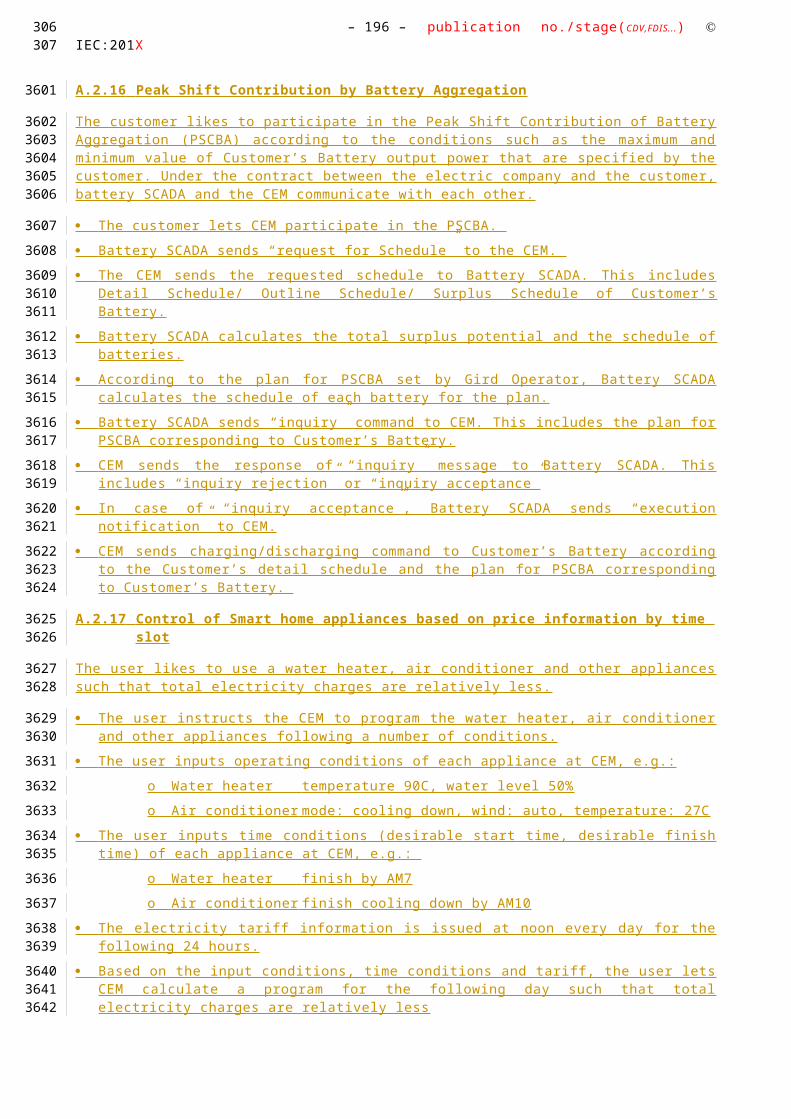
– 196 – publication no./stage(CDV,FDIS...) IEC:201X
air conditioning and cooling devices with thermal inertia, etc…) . The smart device can receive data directly from the grid, though an interface with the CEM and can react to commands and messages from the grid in an intelligent way.
Since the smart device is outside the scope of the SGCG, it must be seen as an external actor
Triggering Event, Preconditions, Assumptions
Use Case ConditionsActor/System/Information/Contract
Triggering Event Pre-conditions Assumption
References
ReferencesNo. Referenc
es TypeReference Status Impact on
Use CaseOriginator / Organisation Link
1 Guideline Basic definitions and common procedures
Final Terms and definitions
SG-CG Sustainable Processes WG
ftp://ftp.cen.eu/EN/EuropeanStandardization/HotTopics/SmartGrids/Sustainable Processes.pdf
2 Generic Use Case
Additional Information
Final Additional information on Market communication
Smart Grid Coordination Group (SG-CG) Sustainable Processes WGSP2128
-
3 High Level Use Case
Direct relevance
Draft Terms and definitions
Joint Use Case Working Group (IEC TC57 WG21/ CLC TC205 WG18 / CLC TC59x WG7)
Further Information to the Use Case for Classification / Mapping
Classification InformationRelation to Other Use Cases Level of Depth
Specific Level Use Case
Prioritisation Generic, Regional or National Relation
Specific High Level Use Case which can be applied to any kind of Smart Device.
Viewpoint
This Specific Use Case has the User perspective and the interaction of the SD with an overall energy management system. It does not consider market mechanisms for flexibility offering or power grid specific implementations.
Further Keywords for Classification
Specific Use Case
279
3454
3455
3456
3457
3458
3459

Use Case Name: – 197 –Energy Flexibility Management
A.4.4.4 Step by Step Analysis of Use Case
Steps – Scenario Name
Scenario ConditionsNo. Scenario
NamePrimary Actor Triggering Event Pre-Condition Post-Condition
Steps – Scenarios
ScenarioScenario Name :
No. 1 - Flexible start time of appliance
Step No.
Event Name of Process/ Activity
Description of Process/ Activity
Service Information Producer (Actor)
Information Receiver (Actor)
Information Requirements , R-ID Exchanged
1 Activation Message
Operation mode preparation
The CEM or the User activates a specific operational mode on a Smart device.
Preparation
User/CEM SD Device Specific (Button Pressed, Request from CEM to ask for flexibility, Timer on the SD, SD internal state change, …)
2 - SD calculates its capabilities
There might be various possibilities depending on the state and its operational mode which must be evaluated of the SD.
Preparation
SD SD -
3 SD Notification
SD informs CEM
SD sends the information of the flexible start to the CEM.
Flexibility Service offering
SD CEM Start Time, End Time Energy Profile (estimated energy consumption)
280281
3460
3461
3462
3463
3464

– 198 – publication no./stage(CDV,FDIS...) IEC:201X
A.4.4.5 Information ExchangedInformation Exchanged
Name of Information (ID)
Description of Information Exchanged Requirements to information data
Assigned start time General Device Data (GDD) As defined for GDD within JWG-HLUC1.1 .
A.4.4.6 Common Terms and DefinitionsCommon Terms and Definitions
Term Definition
A.4.4.7 Custom Information (optional)Custom Information (optional)
Key Value Refers to Section
282
3465
3466
3467
3468
3469
3470

Use Case Name: – 199 –Energy Flexibility Management
A.4.5 SPECIFIC USE CASE (JWG1103) CEM informs SD about slot shift
A.4.5.1 Description of the Use Case
Name of Use Case
Use Case IdentificationID Domain(s)/
Zone(s)Name of Use Case
JWG1101
Domain: Customer Premises, DER
Zones:Process, Field, Station
CEM informs SD about slot shift by sending an upated energy profile.
Version Management
Version ManagementChanges / Version
Date Name Author(s) or Committee
Domain Expert
Area of Expertise / Domain / Role
Title/Changes Approval Statusdraft, for comments, for voting, f inal
0.1 Mar 07, 2014
Stephan Fertig (CLC TC59x WG7)
Editor Initial Draft Draft
Scope and Objectives of Use Case
Scope and Objectives of Use Case
Scope After a Smart Device was able to register at the CEM and works properly, it received a schedule from the CEM. The SD is configured properly and the CEM knows about it.
Objective(s) This use case defines the basic information which is required to inform the SD about a change in its running schedule. The CEM might recalculate the schedule due to whatever reason and might inform the SD on this outcome.
Related business case(s)
- Demand Response (DR)
- Demand Side Management (DSM)
Narrative of Use Case
Narrative of Use Case
Short description
This Use Case shifts the running time of a Smart Deice by updating the Energy Profile. The SD will the reconfigure and modify according to the information provided within the energy profile.
283284
34713472
3473
3474
3475
3476
3477
3478
3479
3480

– 200 – publication no./stage(CDV,FDIS...) IEC:201X
Complete description
The CEM receives from any external source information, which triggers a recalculation of the overall energy schedule. Triggering information can be a new selected energy optimization scheme selected by the User, updated tariff information, a demand response request from an external actor, or anything else.
The overall energy schedule that the CEM manages includes all registered Smart Devices. Some of these devices might offer flexibility to the CEM. That capability must be available at the CEM to shuffle around power consumption at customer premises.
After the CEM has estimated energy profiles for each Smart Device that has been registered to the CEM, it will send an update of the energy profile. The energy profile contains one or more slots which indicate a device specific running mode of each device. That specific running mode must not be known by the CEM but the power consumption shall not be exceeded.
The Smart Device confirms the new energy profile after verifying its schedule.
General Remarks
General Remarks
A.4.5.2 Diagrams of Use CaseDiagram of Use Case
A.4.5.3 Technical Detais
Actors: People, Systems, Applications, Databases, the Power System, and Other Stakeholders
For the definition of this use case, the following architecture has been used as a basis.
Note that the actors in the above architecture are functional entities, which means that some of them may be part of the same physical device (e.g. CEM functionality may be part of a smart device, the smart meter might also encompass the smart metering gateway and CEM, etc…).
CEM Smart Device*
Simple external consumer
display
Actor AEnergy
management gateway (EMG)
Smart Metering gateway (LNAP )
Smart meter functionalityActor B
Energy Management / Providing Flexibility (M490)
M441 architecture
Market communication
* e.g. HBES device, smart appliances, storage, generator, domestic charger for EV, complex display
Smart Grid Connection
Point
Functional metering reference architecture according the SM-CG (TR50572)
285
3481
3482
3483
3484
3485
34863487
3488
3489
349034913492

Use Case Name: – 201 –Energy Flexibility Management
Please consider that the scope of this high level use does not require all actors shown on the figure above. Following table shows involved actors.
ActorsGrouping (Community) Group Description Actor Namesee Actor List
Actor Type see Actor List
Actor Description see Actor List
Further information specific to this Use Case
Customer Energy Manager
InternalThe CEM is a logical function optimising energy consumption and or production based on messages received from the grid, consumer’s settings and contracts, and devices minimum performance standards. The Customer Energy Manager collects messages sent to and received from connected devices; especially the in-home/building sector has to be mentioned. It can handle general or dedicated load and generation management commands and then forwards these to the connected devices. It provides vice versa information towards the “grid / market”. Note that multiple loads/generation resources can be combined in the CEM to be mutually controlled.
When the CEM is integrated with communication functionalities it is called a Customer Energy Management System or CEMS
Smart deviceExternal
A smart device may be an appliance, generator or storage device (Local storage devices include direct and functional electricity storages such as electrochemical batteries, heat pumps and micro CHP such as fuel cells with heat buffers, air conditioning and cooling devices with thermal inertia, etc…) . The smart device can receive data directly from the grid, though an interface with the CEM and can react to commands and messages from the grid in an intelligent way.
Since the smart device is outside the scope of the SGCG, it must be seen as an external actor
Triggering Event, Preconditions, Assumptions
Use Case ConditionsActor/System/Information/Contract
Triggering Event Pre-conditions Assumption
CEM
Rescheduling event SD and CEM are active and operational.
User has created or selected a profile before creating the event. CEM starts negotiations with SD based on the profile.
References
ReferencesNo. Referenc
es TypeReference Status Impact on
Use CaseOriginator / Organisation Link
286287
3493349434953496
3497
3498
3499
3500

– 202 – publication no./stage(CDV,FDIS...) IEC:201X
1 Guideline Basic definitions and common procedures
Final Terms and definitions
SG-CG Sustainable Processes WG
ftp://ftp.cen.eu/EN/EuropeanStandardization/HotTopics/SmartGrids/Sustainable Processes.pdf
2 Generic Use Case
Additional Information
Final Additional information on Market communication
Smart Grid Coordination Group (SG-CG) Sustainable Processes WGSP2128
-
3 High Level Use Case
Direct relevance
Draft Terms and definitions
Joint Use Case Working Group (IEC TC57 WG21/ CLC TC205 WG18 / CLC TC59x WG7)
Further Information to the Use Case for Classification / Mapping
Classification InformationRelation to Other Use Cases Level of Depth
Specific Level Use Case
Prioritisation Generic, Regional or National Relation
Specific High Level Use Case which can be applied to any kind of Smart Device.
Viewpoint
This Specific Use Case has the User perspective and the interaction of the SD with an overall energy management system. It does not consider market mechanisms for flexibility offering or power grid specific implementations.
Further Keywords for Classification
Specific Use Case
A.4.5.4 Step by Step Analysis of Use Case
Steps – Scenario Name
Scenario ConditionsNo. Scenario
NamePrimary Actor Triggering Event Pre-Condition Post-Condition
Steps – Scenarios
ScenarioScenario Name :
No. 1 - Flexible start time of appliance
Step No.
Event Name of Process/ Activity
Description of Process/ Activity
Service Information Producer (Actor)
Information Receiver (Actor)
Information Requirements , R-ID Exchanged
1 Activation Message
Recalculation of an operational schedule
The CEM received an event on which it recalculates an optimal schedule for the Smart
Preparation
User/Actor A/Actor B/SD
CEM Device Specific (Button Pressed, DR event coming from the Grid, Tariff information,
288
3501
3502
3503
3504
3505
3506
3507

Use Case Name: – 203 –Energy Flexibility Management
Devices that are registered to the CEM.
emergency signal,…)
2 Update CEM send an updated schedule to the SD
The updated schedule is included in the energy profile.
Update Request
CEM SD -
3 Confirmation
SD confirms new schedule
Since the CEM knows about the flexibility of the SD, the new proposed energy profile shall be accepted by the SD.
Confirmation
SD CEM Confirmed Energy Profile (estimated energy consumption, slots, etc.)
Information Exchanged
Information ExchangedName of Information (ID)
Description of Information Exchanged Requirements to information data
Updated Energy Profile
Energy Profile As defined for the Energy Profile within JWG1100 .
Common Terms and Definitions
Common Terms and DefinitionsTerm Definition
Energy Profile An energy profile defines the power consumption/generation over time. The power might vary on the smart device which will be captured and visualized by the energy profile.
An energy profile might be split into multiple time slots. Such time slots have a fix amount of power to get a discrete power consumption/generation profile. A simple energy profile will contain only one power value and its duration.
Custom Information (optional)
Custom Information (optional)Key Value Refers to Section
289290
3508
3509
3510
3511
3512
3513
3514
Stephan Fertig, 09/03/14,
Yes, It contains flexibility in energy consumption (power value) and time of use (duration)
Katsuyoshi Naka, 09/03/14,
The energy profile includes both estimated energy consumption per each slot and amount of flexibility per each slot, is it right ?

– 204 – publication no./stage(CDV,FDIS...) IEC:201X
A.4.6 HIGH LEVEL USE CASE (JWG 1110 ) Temperature Control of Smart appliances based on price information
A.4.6.1 Description of the Use Case
Name of Use Case
Use Case IdentificationID Domain(s)/
Zone(s)Name of Use Case
JWG1110
Domain: Customer Premises, DER
Zones:Process, Field, Station
Con tr ol of Smart home appliances based on price information by time slot
Version Management
Version ManagementChanges / Version
Date Name Author(s) or Committee
Domain Expert
Area of Expertise / Domain / Role
Title/Changes Approval Statusdraft, for comments, for voting, f inal
0.1 Mar 07, 2014
Stephan Fertig (CLC TC59x WG7)
Home Appliances
Use Cases
Initial Draft Draft
291
35153516
3517
3518
3519
3520
3521

Use Case Name: – 205 –Energy Flexibility Management
Scope and Objectives of Use Case
Scope and Objectives of Use Case
Scope With proper management/instruction by CEM, Simple Device such as water heater, air conditioner and other appliances can act Smart. Smart Device which react to some limited simple commands and messages or Simple Device which equips sophisticated thermostat, adopter (e.g. on/off tap) etc. fall within the scope of this Use Case.
Objective(s) This Use Case defines the basic Message which is required to manage simple devices by CEM such that total electricity charges are relatively less.
Related business case(s)
- Demand Response (DR)
- Demand Side Management (DSM)
Narrative of Use Case
Narrative of Use CaseShort description The user inputs operating conditions of each appliance at CEM .
The electricity tariff information is issued at noon every day for the following 24 hours.
Based on the input conditions, time conditions and tariff, the user lets CEM calculate a program for the following day such that total electricity charges are relatively less
CEM controls each appliance as programmed according to conditions of operating planComplete description
The user likes to use a water heater, air conditioner and other appliances such that total electricity charges are relatively less.
The user instructs the CEM to program the water heater, air conditioner and other appliances following a number of conditions.
The user inputs operating conditions of each appliance at CEM, e.g.:
o Water heater temperature 90C, water level 50%
o Air conditioner mode: cooling down, wind: auto, temperature: 27C
The user inputs time conditions (desirable start time, desirable finish time) of each appliance at CEM, e.g.:
o Water heater finish by AM7
o Air conditioner finish cooling down by AM10
The electricity tariff information is issued at noon every day for the following 24 hours.
Based on the input conditions, time conditions and tariff, the user lets CEM calculate a program for the following day such that total electricity charges are relatively less
CEM calculates an operating plan for those appliances considering operation time, power consumption during operation, electricity charges and so forth
The user confirms the calculation results and commits the operating plan to be executed
o CEM controls each appliance as programmed according to conditions of operating plan
General Remarks
General Remarks
292293
3522
3523
3524
3525
3526
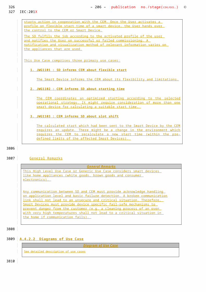
– 206 – publication no./stage(CDV,FDIS...) IEC:201X
Diagrams of Use Case
Diagram of Use Case
294
3527
3528
3529

Use Case Name: – 207 –Energy Flexibility Management
A.4.6.2 Technical Details
Actors: People, Systems, Applications, Databases, the Power System, and Other Stakeholders
For the definition of this use case, the following architecture has been used as a basis.
Note that the actors in the above architecture are functional entities, which means that some of them may be part of the same physical device (e.g. CEM functionality may be part of a smart device, the smart meter might also encompass the smart metering gateway and CEM, etc…).
Please consider that the scope of this high level use does not require all actors shown on the figure above. Following table shows involved actors.
ActorsGrouping (Community) Group Description Actor Namesee Actor List
Actor Type see Actor List
Actor Description see Actor List
Further information specific to this Use Case
Customer Energy Manager
InternalThe CEM is a logical function optimising energy consumption and or production based on messages received from the grid, consumer’s settings and contracts, and devices minimum performance standards. The Customer Energy Manager collects messages sent to and received from connected devices; especially the in-home/building sector has to be mentioned. It can handle general or dedicated load and generation management commands and then forwards these to the connected devices. It provides vice versa information towards the “grid / market”. Note that multiple loads/generation resources can be combined in the CEM to be mutually controlled. When the CEM is integrated with communication functionalities it is called a Customer Energy Management System or CEMS
Smart ThermostatExternal
Using a Smart or programmable thermostat, one can adjust the temperature settings or the times turn on the heating or air-conditioning according to a pre-set schedule. Smart or programmable thermostats can store and repeat multiple daily settings (six or more temperature settings a day) that one can
CEM Smart Device*
Simple external consumer
display
Actor AEnergy
management gateway (EMG)
Smart Metering gateway (LNAP )
Smart meter functionalityActor B
Energy Management / Providing Flexibility (M490)
M441 architecture
Market communication
* e.g. HBES device, smart appliances, storage, generator, domestic charger for EV, complex display
Smart Grid Connection
Point
Functional metering reference architecture according the SM-CG (TR50572)
295296
3530
35313532
3533
3534
3535353635373538353935403541
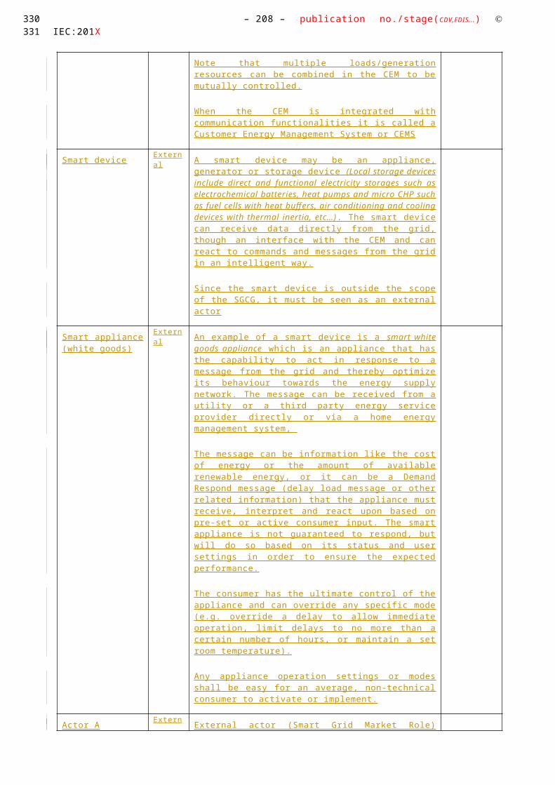
– 208 – publication no./stage(CDV,FDIS...) IEC:201X
manually override without affecting the rest of the daily or weekly program.
One can access it via the web using your tablet, smart phone or computer . The Smart Thermostat can be a device which is connected to the CEM and is programmed its settings from the CEM.
Smart deviceExternal
A smart device may be an appliance, generator or storage device (Local storage devices include direct and functional electricity storages such as electrochemical batteries, heat pumps and micro CHP such as fuel cells with heat buffers, air conditioning and cooling devices with thermal inertia, etc…) . The smart device can receive data directly from the grid, though an interface with the CEM and can react to commands and messages from the grid in an intelligent way.
Since the smart device is outside the scope of the SGCG, it must be seen as an external actor
Smart appliance (white goods)
ExternalAn example of a smart device is a smart white goods appliance which is an appliance that has the capability to act in response to a message from the grid and thereby optimize its behaviour towards the energy supply network. The message can be received from a utility or a third party energy service provider directly or via a home energy management system,
The message can be information like the cost of energy or the amount of available renewable energy, or it can be a Demand Respond message (delay load message or other related information) that the appliance must receive, interpret and react upon based on pre-set or active consumer input. The smart appliance is not guaranteed to respond, but will do so based on its status and user settings in order to ensure the expected performance.
The consumer has the ultimate control of the appliance and can override any specific mode (e.g. override a delay to allow immediate operation, limit delays to no more than a certain number of hours, or maintain a set room temperature).
Any appliance operation settings or modes shall be easy for an average, non-technical consumer to activate or implement.
Actor AExternal
External actor (Smart Grid Market Role) interacting with the system functions and components in the home or home automation network through the energy management communication channel.. Examples of such market roles are the Energy Provider, the Energy Services Provider, the aggregator, etc…
Actor BExternal
External actor (Smart Grid Market Role) interacting with the system functions and components in the home or home automation network through the metering communication channel. This actor is responsible for collecting metering data. Examples of such market roles are the DSO, metering company, etc.
UserExternal
The end customer who has acquired a smart device. The end customer is responsible for configuring and setting
297

Use Case Name: – 209 –Energy Flexibility Management
operation mode of the Smart Device.
Triggering Event, Preconditions, Assumptions
Use Case ConditionsActor/System/Information/Contract
Triggering Event Pre-conditions Assumption
Tariff Information. CEM controls each appliance as programmed according to conditions of operating plan or CEM controls appliance by setting profile (e.g. temperature profile, Timer) defined according to conditions of operating plan
References
ReferencesNo. Referenc
es TypeReference Status Impact on
Use CaseOriginator / Organisation Link
1 Guideline Basic definitions and common procedures
Final Terms and definitions
SG-CG Sustainable Processes WG
ftp://ftp.cen.eu/EN/EuropeanStandardization/HotTopics/SmartGrids/Sustainable Processes.pdf
2 Technical Report
User Story and Sequence diagrams
Draft Major impact on Scenario
IEC TC57 / CLC TC205 / CLC /TC59x
-
3 Standard Use Case Template
Draft (FDIS)
Template desctription
IEC TC8 -
Further Information to the Use Case for Classification / Mapping
Classification InformationRelation to Other Use Cases Level of Depth
High Level Use Case
Prioritisation Generic, Regional or National Relation
High Level Use Case which can be applied to any kind of Smart Device. Once the regions agreed and confirmed correctness, that high level use case becomes a generic use case.
Viewpoint
This High Level Use Case has the User perspective and the interaction of the SD with an overall energy management system. It does not consider market mechanisms for flexibility offering or power
298299
3542
3543
3544
3545
3546
3547
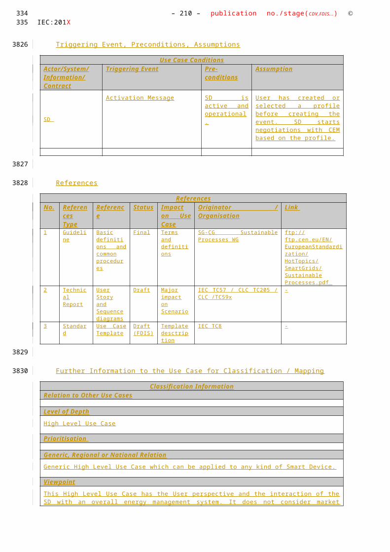
– 210 – publication no./stage(CDV,FDIS...) IEC:201X
grid specific implementations.
Further Keywords for Classification
Generic High Level Use Case
A.4.6.3 Step by Step Analysis of Use Case
Steps – Scenario Name
Scenario ConditionsNo. Scenario
NamePrimary Actor Triggering Event Pre-Condition Post-Condition
Steps – Scenarios
ScenarioScenario Name :
No. 1 - Flexible start time of appliance
Step No.
Event Name of Process/ Activity
Description of Process/ Activity
Service Information Producer (Actor)
Information Receiver (Actor)
Information Requirements , R-ID Exchanged
1 Issued at noon every day
Tariff information
The CEM receives Tariff information .
Preparation
External Actor
CEM Tariff
2 User preference
The user inputs operating conditions of SD
Preparation
User/CEM CEM/User
3 - CEM calculates an operating plan
The CEM calculates an operating plan based on the Tariff information and User input .
Preparation
CEM CEM -
3 CEM Notification
CEM sets profile to SD
CEM set s the simple command or profile (e.g. temperature profile) to SD .
Simple SD management
CEM SD S et On/Off/Start/Stop/Pause/Resume/Abort/DimSet Profile
300
3548
3549
3550
3551
3552

Use Case Name: – 211 –Energy Flexibility Management
A.4.6.4 Information ExchangedInformation Exchanged
Name of Information (ID)
Description of Information Exchanged Requirements to information data
Simple Commands On/Off/Start/Stop/Pause/Resume/Abort/DimTimerA ir conditioner mode:
cooling down, heating up, mode 1-nW ind: auto, high, low, etcOther settings:
Such information is sensitive in a way that any modification might turn on or off a SD
Therefore, the communication data must be protected from misuse and external influences.
Temperature Profile A temperature profile defines the temperature set point over time (e.g. set point of each room temperature). A temperature profile might be split into multiple time slots. Such time slots have a fix amount of temperature to set a discrete temperature profile. A simple temperature profile will contain only one temperature value and its duration and there might be weekly temperature profiles each of which contains weekdays (Monday to Friday) / weekend profile.
Temperature Profile is sensitive in a way that any modification might affect drastic room temperature change.
Therefore, the communication data must be protected from misuse and external influences.
A.4.6.5 Requirements (optional)
A.4.6.6 Common Terms and DefinitionsCommon Terms and Definitions
Term DefinitionTemperature Profile A temperature profile defines the temperature set point over time (e.g.
set point of each room temperature). A temperature profile might be split into multiple time slots. Such time slots have a fix amount of temperature to set a discrete temperature profile. A simple temperature profile will contain only one temperature value and its duration and there might be weekly temperature profiles each of which contains weekdays (Monday to Friday) / weekend profile.
A.4.6.7 Custom Information (optional)Custom Information (optional)
Key Value Refers to Section
301302
3553
3554
3555
3556
3557
3558

– 212 – publication no./stage(CDV,FDIS...) IEC:201X
A.4.7 HIGH LEVEL USE CASE (JWG 1110 ) Fuel Cell Operation with Fixed Tariff Profile
A.4.7.1 Description of the Use Case
Name of Use Case
Use Case IdentificationID Domain(s)/
Zone(s)Name of Use Case
JWG1111
Domain: Customer Premises, DER
Zones:Process, Field, Station
Control of Fuel Cell (FC) operation according to a fixed tariff schedule (profile).
Version Management
Version ManagementChanges / Version
Date Name Author(s) or Committee
Domain Expert
Area of Expertise / Domain / Role
Title/Changes Approval Statusdraft, for comments, for voting, f inal
0.1 Mar 07, 2014
Stephan Fertig (CLC TC59x WG7)
Home Appliances
Use Cases
Initial Draft Draft
303
35593560
3561
3562
3563
3564
3565

Use Case Name: – 213 –Energy Flexibility Management
Scope and Objectives of Use Case
Scope and Objectives of Use Case
Scope This use case describes the control of a fuel cell by a home Energy Management System (EMS) based upon tariff schedule (a profile of price for a given set of intervals) information received from an Energy Supplier. The objective is to minimise the amount of electrical energy imported from the grid.
Objective(s) Optimum operation (for energy efficiency and minimising carbon emissions) requires knowledge of forecast pricing for future tariff intervals, building characteristics (e.g. thermal mass), current conditions (e.g. temperature) and the occupant’s desired system behaviour (e.g. future temperature profile). This may be considered in other compound/elaborated used cases.
Related business case(s)
- Demand Response (DR)
- Demand Side Management (DSM)
Narrative of Use Case
Narrative of Use CaseShort description
This use case describes the control of a domestic fuel cell by a home Energy Management System (EMS) based upon tariff schedule (a profile of price for a given set of intervals) information received from an Energy Supplier. The EMS requests the fuel to turn on/increase output or turn off/decrease output depending upon both the tariff schedule information received from the Energy Supplier and a tariff (price) threshold set by the Home Customer.
Complete description
This use case assumes that the EMS receives tariff schedule (a profile of price for a given set of intervals) information from the Energy Supplier.
In this use case, an EMS sends requests to, and receives notifications from, a Fuel Cell Controller. The fuel cell controller has responsibility for controlling the operation of the Fuel Cell sub-system and may override the requests from the EMS if necessary.
This use case assumes that the Home Customer has set a threshold for the real-time tariff (price) value, above which the fuel cell will normally be turned on.
The Home Customer ’s EMS receives tariff schedule information from the energy supplier. The tariff schedule may be valid for a given period or until a new tariff schedule is provided.
If the price of that interval exceeds the threshold, then at the beginning of that interval the EMS controller sends a fuel cell turn on request or a fuel cell increase output by x Watt request to the Fuel Cell Controller in order to turn on the Fuel Cell, or to increase the Fuel Cell output, for that interval. The Fuel Cell Controller sends a status message to the EMS controller in order to indicate that the command has been successfully implemented or not.
If the price for an interval is below or equal to the threshold set by the Home Customer, then at the beginning of that interval the EMS controller sends a fuel cell turn off request or a fuel cell decrease output by y Watt request to the Fuel Cell Controller in order to turn off the Fuel Cell, or to decrease the Fuel Cell output, for that interval. The Fuel Cell Controller sends a status message to the EMS controller in order to indicate that the command has been successfully implemented or not.
304305
3566
3567
3568
3569

– 214 – publication no./stage(CDV,FDIS...) IEC:201X
General Remarks
General Remarks
A.4.7.2 Diagrams of Use CaseDiagram of Use Case
306
3570
3571
3572
3573

Use Case Name: – 215 –Energy Flexibility Management
A.4.7.3 Technical Details
Actors: People, Systems, Applications, Databases, the Power System, and Other Stake -holders
For the definition of this use case, the following architecture has been used as a basis.
Note that the actors in the above architecture are functional entities, which means that some of them may be part of the same physical device (e.g. CEM functionality may be part of a smart device, the smart meter might also encompass the smart metering gateway and CEM, etc…).
Please consider that the scope of this high level use does not require all actors shown on the figure above. Following table shows involved actors.
ActorsGrouping (Community) Group Description Actor Namesee Actor List
Actor Type see Actor List
Actor Description see Actor List
Further information specific to this Use Case
Customer Energy Manager
InternalThe CEM is a logical function optimising energy consumption and or production based on messages received from the grid, consumer’s settings and contracts, and devices minimum performance standards. The Customer Energy Manager collects messages sent to and received from connected devices; especially the in-home/building sector has to be mentioned. It can handle general or dedicated load and generation management commands and then forwards these to the connected devices. It provides vice versa information towards the “grid / market”. Note that multiple loads/generation resources can be combined in the CEM to be mutually controlled. When the CEM is integrated with communication functionalities it is called a Customer Energy Management System or CEMS
Smart ThermostatExternal
Using a Smart or programmable thermostat, one can adjust the temperature settings or the times turn on the heating or air-conditioning according to a pre-set schedule. Smart or programmable thermostats can store and repeat multiple daily settings (six or more temperature settings a day) that one can
CEM Smart Device*
Simple external consumer
display
Actor AEnergy
management gateway (EMG)
Smart Metering gateway (LNAP )
Smart meter functionalityActor B
Energy Management / Providing Flexibility (M490)
M441 architecture
Market communication
* e.g. HBES device, smart appliances, storage, generator, domestic charger for EV, complex display
Smart Grid Connection
Point
Functional metering reference architecture according the SM-CG (TR50572)
307308
3574
357535763577
3578
3579358035813582358335843585

– 216 – publication no./stage(CDV,FDIS...) IEC:201X
manually override without affecting the rest of the daily or weekly program.
One can access it via the web using your tablet, smart phone or computer . The Smart Thermostat can be a device which is connected to the CEM and is programmed its settings from the CEM.
Smart deviceExternal
A smart device may be an appliance, generator or storage device (Local storage devices include direct and functional electricity storages such as electrochemical batteries, heat pumps and micro CHP such as fuel cells with heat buffers, air conditioning and cooling devices with thermal inertia, etc…) . The smart device can receive data directly from the grid, though an interface with the CEM and can react to commands and messages from the grid in an intelligent way.
Since the smart device is outside the scope of the SGCG, it must be seen as an external actor
Smart appliance (white goods)
ExternalAn example of a smart device is a smart white goods appliance which is an appliance that has the capability to act in response to a message from the grid and thereby optimize its behaviour towards the energy supply network. The message can be received from a utility or a third party energy service provider directly or via a home energy management system,
The message can be information like the cost of energy or the amount of available renewable energy, or it can be a Demand Respond message (delay load message or other related information) that the appliance must receive, interpret and react upon based on pre-set or active consumer input. The smart appliance is not guaranteed to respond, but will do so based on its status and user settings in order to ensure the expected performance.
The consumer has the ultimate control of the appliance and can override any specific mode (e.g. override a delay to allow immediate operation, limit delays to no more than a certain number of hours, or maintain a set room temperature).
Any appliance operation settings or modes shall be easy for an average, non-technical consumer to activate or implement.
Actor AExternal
External actor (Smart Grid Market Role) interacting with the system functions and components in the home or home automation network through the energy management communication channel.. Examples of such market roles are the Energy Provider, the Energy Services Provider, the aggregator, etc…
Actor BExternal
External actor (Smart Grid Market Role) interacting with the system functions and components in the home or home automation network through the metering communication channel. This actor is responsible for collecting metering data. Examples of such market roles are the DSO, metering company, etc.
UserExternal
The end customer who has acquired a smart device. The end customer is responsible for configuring and setting
309
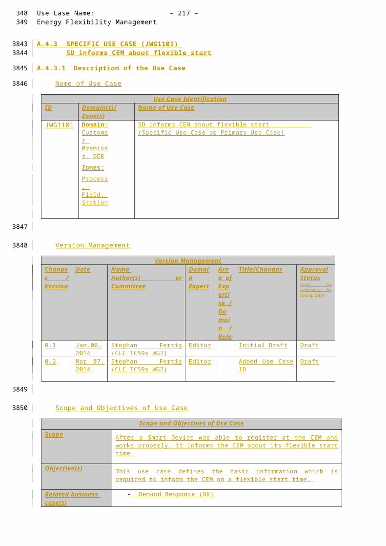
Use Case Name: – 217 –Energy Flexibility Management
operation mode of the Smart Device.
A.4.7.4 Triggering Event, Preconditions, AssumptionsUse Case Conditions
Actor/System/Information/Contract
Triggering Event Pre-conditions Assumption
Tariff Information. CEM controls each appliance as programmed according to conditions of operating plan or CEM controls appliance by setting profile (e.g. temperature profile, Timer) defined according to conditions of operating plan
References
ReferencesNo. Referenc
es TypeReference Status Impact on
Use CaseOriginator / Organisation Link
1 Guideline Basic definitions and common procedures
Final Terms and definitions
SG-CG Sustainable Processes WG
ftp://ftp.cen.eu/EN/EuropeanStandardization/HotTopics/SmartGrids/Sustainable Processes.pdf
2 Technical Report
User Story and Sequence diagrams
Draft Major impact on Scenario
IEC TC57 / CLC TC205 / CLC /TC59x
-
3 Standard Use Case Template
Draft (FDIS)
Template desctription
IEC TC8 -
Further Information to the Use Case for Classification / Mapping
Classification InformationRelation to Other Use Cases Level of Depth
High Level Use Case
Prioritisation Generic, Regional or National Relation
High Level Use Case which can be applied to any kind of Smart Device. Once the regions agreed and confirmed correctness, that high level use case becomes a generic use case.
Viewpoint
This High Level Use Case has the User perspective and the interaction of the SD with an overall energy management system. It does not consider market mechanisms for flexibility offering or power grid specific implementations.
310311
3586
3587
3588
3589
3590
3591

– 218 – publication no./stage(CDV,FDIS...) IEC:201X
Further Keywords for Classification
Generic High Level Use Case
A.4.7.5 Step by Step Analysis of Use Case
Steps – Scenario Name
Scenario ConditionsNo. Scenario
NamePrimary Actor Triggering Event Pre-Condition Post-Condition
Steps – Scenarios
ScenarioScenario Name :
No. 1 - Flexible start time of appliance
Step No.
Event Name of Process/ Activity
Description of Process/ Activity
Service Information Producer (Actor)
Information Receiver (Actor)
Information Requirements , R-ID Exchanged
1 Issued at noon every day
Tariff information
The CEM receives Tariff information .
Flexible Tariff
External Actor
CEM Tariff
2 - Calculate schedule for Smart Device
Calculate the optimal running time for the Smart Device
Preparation
CEM CEM
3 New command for SD available
Turn on/off Smart Device
The CEM send a command to the SD to turn it on/off/pause/etc.
Response to new tariff signal
CEM SD S et On/Off/Start/Stop/Pause/Resume/Abort/DimSet Profile
3 - SD confirms command
The SD confirms the command by responding accordingly
Confirmation
SD CEM -
312
3592
3593
3594
3595
3596

Use Case Name: – 219 –Energy Flexibility Management
A.4.7.6 Information ExchangedInformation Exchanged
Name of Information (ID)
Description of Information Exchanged Requirements to information data
Simple Commands On/Off/Start/Stop/Pause/Resume/Abort/DimTimerA ir conditioner mode:
cooling down, heating up, mode 1-nW ind: auto, high, low, etcOther settings:
Such information is sensitive in a way that any modification might turn on or off a SD
Therefore, the communication data must be protected from misuse and external influences.
Tariff Information Tariff information might be split into multiple time slots. Such time slots have a fix value for a certain period of time to set a discrete profile. A simple temperature profile will contain only one temperature value and its duration and there might be weekly temperature profiles each of which contains weekdays (Monday to Friday) / weekend profile.
Temperature Profile is sensitive in a way that any modification might affect drastic room temperature change.
Therefore, the communication data must be protected from misuse and external influences.
A.4.7.7 Requirements (optional)
A.4.7.8 Common Terms and DefinitionsCommon Terms and Definitions
Term Definition
A.4.7.9 Custom Information (optional)Custom Information (optional)
Key Value Refers to Section
313314
3597
3598
3599
3600
3601
3602

– 220 – publication no./stage(CDV,FDIS...) IEC:201X
A.4.8 HIGH LEVEL USE CASE (JWG 1111 ) Fuel Cell Operation with Fixed Tariff Profile
A.4.8.1 Description of the Use Case
Name of Use Case
Use Case IdentificationID Domain(s)/
Zone(s)Name of Use Case
JWG1111
Domain: Customer Premises, DER
Zones:Process, Field, Station
Control of Fuel Cell (FC) operation according to a fixed tariff schedule (profile).
Version Management
Version ManagementChanges / Version
Date Name Author(s) or Committee
Domain Expert
Area of Expertise / Domain / Role
Title/Changes Approval Statusdraft, for comments, for voting, f inal
0.1 Mar 07, 2014
Stephan Fertig (CLC TC59x WG7)
Home Appliances
Use Cases
Initial Draft Draft
315
36033604
3605
3606
3607
3608
3609

Use Case Name: – 221 –Energy Flexibility Management
Scope and Objectives of Use Case
Scope and Objectives of Use Case
Scope This use case describes the control of a fuel cell by a home Energy Management System (EMS) based upon tariff schedule (a profile of price for a given set of intervals) information received from an Energy Supplier. The objective is to minimise the amount of electrical energy imported from the grid.
Objective(s) Optimum operation (for energy efficiency and minimising carbon emissions) requires knowledge of forecast pricing for future tariff intervals, building characteristics (e.g. thermal mass), current conditions (e.g. temperature) and the occupant’s desired system behaviour (e.g. future temperature profile). This may be considered in other compound/elaborated used cases.
Related business case(s)
- Demand Response (DR)
- Demand Side Management (DSM)
Narrative of Use Case
Narrative of Use CaseShort description
This use case describes the control of a domestic fuel cell by a home Energy Management System (EMS) based upon tariff schedule (a profile of price for a given set of intervals) information received from an Energy Supplier. The EMS requests the fuel to turn on/increase output or turn off/decrease output depending upon both the tariff schedule information received from the Energy Supplier and a tariff (price) threshold set by the Home Customer.
Complete description
This use case assumes that the EMS receives tariff schedule (a profile of price for a given set of intervals) information from the Energy Supplier.
In this use case, an EMS sends requests to, and receives notifications from, a Fuel Cell Controller. The fuel cell controller has responsibility for controlling the operation of the Fuel Cell sub-system and may override the requests from the EMS if necessary.
This use case assumes that the Home Customer has set a threshold for the real-time tariff (price) value, above which the fuel cell will normally be turned on.
The Home Customer ’s EMS receives tariff schedule information from the energy supplier. The tariff schedule may be valid for a given period or until a new tariff schedule is provided.
If the price of that interval exceeds the threshold, then at the beginning of that interval the EMS controller sends a fuel cell turn on request or a fuel cell increase output by x Watt request to the Fuel Cell Controller in order to turn on the Fuel Cell, or to increase the Fuel Cell output, for that interval. The Fuel Cell Controller sends a status message to the EMS controller in order to indicate that the command has been successfully implemented or not.
If the price for an interval is below or equal to the threshold set by the Home Customer, then at the beginning of that interval the EMS controller sends a fuel cell turn off request or a fuel cell decrease output by y Watt request to the Fuel Cell Controller in order to turn off the Fuel Cell, or to decrease the Fuel Cell output, for that interval. The Fuel Cell Controller sends a status message to the EMS controller in order to indicate that the command has been successfully implemented or not.
316317
3610
3611
3612
3613

– 222 – publication no./stage(CDV,FDIS...) IEC:201X
General Remarks
General Remarks
A.4.8.2 Diagrams of Use CaseDiagram of Use Case
318
3614
3615
3616
3617

Use Case Name: – 223 –Energy Flexibility Management
A.4.8.3 Technical Details
Actors: People, Systems, Applications, Databases, the Power System, and Other Stake -holders
For the definition of this use case, the following architecture has been used as a basis.
Note that the actors in the above architecture are functional entities, which means that some of them may be part of the same physical device (e.g. CEM functionality may be part of a smart device, the smart meter might also encompass the smart metering gateway and CEM, etc…).
Please consider that the scope of this high level use does not require all actors shown on the figure above. Following table shows involved actors.
ActorsGrouping (Community) Group Description Actor Namesee Actor List
Actor Type see Actor List
Actor Description see Actor List
Further information specific to this Use Case
Customer Energy Manager
InternalThe CEM is a logical function optimising energy consumption and or production based on messages received from the grid, consumer’s settings and contracts, and devices minimum performance standards. The Customer Energy Manager collects messages sent to and received from connected devices; especially the in-home/building sector has to be mentioned. It can handle general or dedicated load and generation management commands and then forwards these to the connected devices. It provides vice versa information towards the “grid / market”. Note that multiple loads/generation resources can be combined in the CEM to be mutually controlled. When the CEM is integrated with communication functionalities it is called a Customer Energy Management System or CEMS
Smart ThermostatExternal
Using a Smart or programmable thermostat, one can adjust the temperature settings or the times turn on the heating or air-conditioning according to a pre-set schedule. Smart or programmable thermostats can store and repeat multiple daily settings (six or more temperature settings a day) that one can
CEM Smart Device*
Simple external consumer
display
Actor AEnergy
management gateway (EMG)
Smart Metering gateway (LNAP )
Smart meter functionalityActor B
Energy Management / Providing Flexibility (M490)
M441 architecture
Market communication
* e.g. HBES device, smart appliances, storage, generator, domestic charger for EV, complex display
Smart Grid Connection
Point
Functional metering reference architecture according the SM-CG (TR50572)
319320
3618
361936203621
3622
3623362436253626362736283629

– 224 – publication no./stage(CDV,FDIS...) IEC:201X
manually override without affecting the rest of the daily or weekly program.
One can access it via the web using your tablet, smart phone or computer . The Smart Thermostat can be a device which is connected to the CEM and is programmed its settings from the CEM.
Smart deviceExternal
A smart device may be an appliance, generator or storage device (Local storage devices include direct and functional electricity storages such as electrochemical batteries, heat pumps and micro CHP such as fuel cells with heat buffers, air conditioning and cooling devices with thermal inertia, etc…) . The smart device can receive data directly from the grid, though an interface with the CEM and can react to commands and messages from the grid in an intelligent way.
Since the smart device is outside the scope of the SGCG, it must be seen as an external actor
Smart appliance (white goods)
ExternalAn example of a smart device is a smart white goods appliance which is an appliance that has the capability to act in response to a message from the grid and thereby optimize its behaviour towards the energy supply network. The message can be received from a utility or a third party energy service provider directly or via a home energy management system,
The message can be information like the cost of energy or the amount of available renewable energy, or it can be a Demand Respond message (delay load message or other related information) that the appliance must receive, interpret and react upon based on pre-set or active consumer input. The smart appliance is not guaranteed to respond, but will do so based on its status and user settings in order to ensure the expected performance.
The consumer has the ultimate control of the appliance and can override any specific mode (e.g. override a delay to allow immediate operation, limit delays to no more than a certain number of hours, or maintain a set room temperature).
Any appliance operation settings or modes shall be easy for an average, non-technical consumer to activate or implement.
Actor AExternal
External actor (Smart Grid Market Role) interacting with the system functions and components in the home or home automation network through the energy management communication channel.. Examples of such market roles are the Energy Provider, the Energy Services Provider, the aggregator, etc…
Actor BExternal
External actor (Smart Grid Market Role) interacting with the system functions and components in the home or home automation network through the metering communication channel. This actor is responsible for collecting metering data. Examples of such market roles are the DSO, metering company, etc.
UserExternal
The end customer who has acquired a smart device. The end customer is responsible for configuring and setting
321
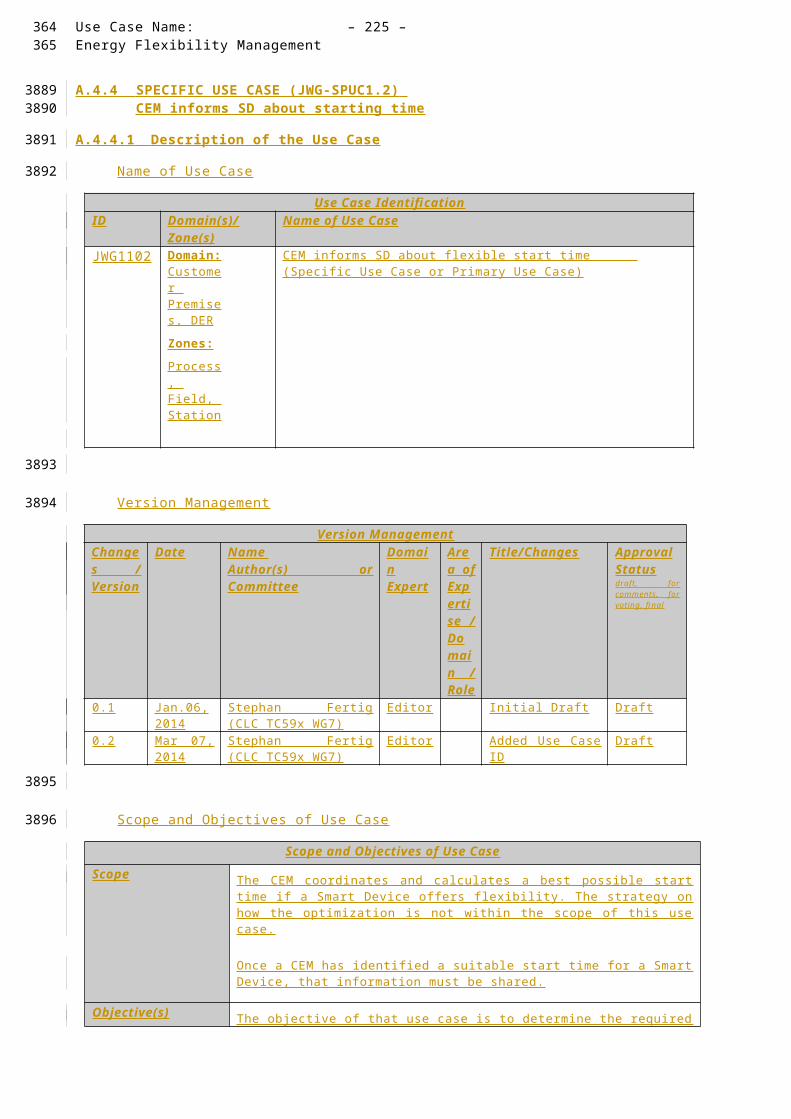
Use Case Name: – 225 –Energy Flexibility Management
operation mode of the Smart Device.
Triggering Event, Preconditions, Assumptions
Use Case ConditionsActor/System/Information/Contract
Triggering Event Pre-conditions Assumption
Tariff Information. CEM controls each appliance as programmed according to conditions of operating plan or CEM controls appliance by setting profile (e.g. temperature profile, Timer) defined according to conditions of operating plan
References
ReferencesNo. Referenc
es TypeReference Status Impact on
Use CaseOriginator / Organisation Link
1 Guideline Basic definitions and common procedures
Final Terms and definitions
SG-CG Sustainable Processes WG
ftp://ftp.cen.eu/EN/EuropeanStandardization/HotTopics/SmartGrids/Sustainable Processes.pdf
2 Technical Report
User Story and Sequence diagrams
Draft Major impact on Scenario
IEC TC57 / CLC TC205 / CLC /TC59x
-
3 Standard Use Case Template
Draft (FDIS)
Template desctription
IEC TC8 -
Further Information to the Use Case for Classification / Mapping
Classification InformationRelation to Other Use Cases Level of Depth
High Level Use Case
Prioritisation Generic, Regional or National Relation
High Level Use Case which can be applied to any kind of Smart Device. Once the regions agreed and confirmed correctness, that high level use case becomes a generic use case.
Viewpoint
This High Level Use Case has the User perspective and the interaction of the SD with an overall energy management system. It does not consider market mechanisms for flexibility offering or power
322323
3630
3631
3632
3633
3634
3635

– 226 – publication no./stage(CDV,FDIS...) IEC:201X
grid specific implementations.
Further Keywords for Classification
Generic High Level Use Case
A.4.8.4 Step by Step Analysis of Use Case
Steps – Scenario Name
Scenario ConditionsNo. Scenario
NamePrimary Actor Triggering Event Pre-Condition Post-Condition
Steps – Scenarios
ScenarioScenario Name :
No. 1 - Flexible start time of appliance
Step No.
Event Name of Process/ Activity
Description of Process/ Activity
Service Information Producer (Actor)
Information Receiver (Actor)
Information Requirements , R-ID Exchanged
1 Issued at noon every day
Tariff information
The CEM receives Tariff information .
Flexible Tariff
External Actor
CEM Tariff
2 - Calculate schedule for Smart Device
Calculate the optimal running time for the Smart Device
Preparation
CEM CEM
3 New command for SD available
Turn on/off Smart Device
The CEM send a command to the SD to turn it on/off/pause/etc.
Response to new tariff signal
CEM SD S et On/Off/Start/Stop/Pause/Resume/Abort/DimSet Profile
3 - SD confirms command
The SD confirms the command by responding accordingly
Confirmation
SD CEM -
324
3636
3637
3638
3639
3640

Use Case Name: – 227 –Energy Flexibility Management
Information Exchanged
Information ExchangedName of Information (ID)
Description of Information Exchanged Requirements to information data
Simple Commands On/Off/Start/Stop/Pause/Resume/Abort/DimTimerA ir conditioner mode:
cooling down, heating up, mode 1-nW ind: auto, high, low, etcOther settings:
Such information is sensitive in a way that any modification might turn on or off a SD
Therefore, the communication data must be protected from misuse and external influences.
Tariff Information Tariff information might be split into multiple time slots. Such time slots have a fix value for a certain period of time to set a discrete profile. A simple temperature profile will contain only one temperature value and its duration and there might be weekly temperature profiles each of which contains weekdays (Monday to Friday) / weekend profile.
Temperature Profile is sensitive in a way that any modification might affect drastic room temperature change.
Therefore, the communication data must be protected from misuse and external influences.
A.4.8.5 Requirements (optional)
A.4.8.6 Common Terms and DefinitionsCommon Terms and Definitions
Term Definition
A.4.8.7 Custom Information (optional)Custom Information (optional)
Key Value Refers to Section
325326
3641
3642
3643
3644
3645
3646

– 228 – publication no./stage(CDV,FDIS...) IEC:201X
A.4.9 HIGH LEVEL USE CASE (JWG 112x ) Mixed Energy System like heat pumps with PV, Storage Battery.
A.4.9.1 Description of the Use Case
Name of Use Case
Use Case IdentificationID Domain(s)/
Zone(s)Name of Use Case
JWG112x
Domain: Customer Premises, DER
Zones:Process, Field, Station
Use Cases that have various energy related devices like heat pumps and energy storage (taken from TR 62746-2 version 0.5.1).
Version Management
Version ManagementChanges / Version
Date Name Author(s) or Committee
Domain Expert
Area of Expertise / Domain / Role
Title/Changes Approval Statusdraft, for comments, for voting, f inal
0.1 Mar 07, 2014
Stephan Fertig (CLC TC59x WG7)
Home Appliances
Use Cases
Initial Draft (taken from TR 62746-2 version 0.5.1)
Draft
327
36473648
3649
3650
3651
3652
3653

Use Case Name: – 229 –Energy Flexibility Management
Scope and Objectives of Use Case
Scope and Objectives of Use Case
Scope With proper management/instruction by CEM, Simple Device such as water heater, air conditioner and other appliances can act Smart. Smart Device which react to some limited simple commands and messages or Simple Device which equips sophisticated thermostat, adopter (e.g. on/off tap) etc. fall within the scope of this Use Case.
Objective(s) This Use Case defines the basic information exchange which is required to heat up the water using a heat pump.
Related business case(s)
- Demand Response (DR)
- Demand Side Management (DSM)
Narrative of Use Case
Narrative of Use CaseShort descriptionThis use case describes the operation of the Heat pump controller in different scenarios.Complete description
JWG1121 – Request for extra hot water using a heat pumpThe Customer has the request to turn on the heat pump for heating up water. As long there is no emergency situation the customer overrules an existing configuration if active. Therefore, the user interface forwards the request to the CEM which then informs the heat pump controller. The heat pump controller activates the hot water generation and informs the CEM accordingly.
JWG1122 - Request for extra hot water using a heat pump and storage batteryThis use case describes the operation of the Heat Pump, EMS and Storage Battery controllers when the customer requests additional hot water in an ad hoc manner (not a scheduled operation).The Heat Pump controller initiates operation of the heat pump to heat water and broadcasts its operation status. The EMS receives this information and requests the Storage Battery controller to initiate storage battery discharge.
JWG1123 - Request for extra hot water using a heat pump and storage batteryThis use case describes the operation of the Heat Pump, EMS and Storage Battery controllers when the customer requests additional hot water in an ad hoc manner (not a scheduled operation).The Heat Pump controller initiates operation of the heat pump to heat water and broadcasts its operation status. The EMS receives this information and requests the Storage Battery controller to initiate storage battery discharge.
JWG1124 - Heat Pump Operation with Real-Time TariffThis use case describes the control of a domestic heat pump by a home Energy Management System (EMS) based upon real time tariff (price) information received from an Energy Supplier. The EMS requests the heat pump to either turn on/increase operating power or turn off/decrease operating power depending upon both real time tariff (price) information received from the Energy Supplier and a tariff (price) threshold set by the Home Customer.
JWG1125 - Heat pump and Photovoltaic Operation with Real-Time TariffThis use case describes the control of a domestic heat pump by a home Energy Management System (EMS) based upon real time tariff (price) information received from an Energy Supplier, when a Photovoltaic (PV) system is in operation. The EMS requests the heat pump to turn on or turn off depending upon both real time tariff (price) information received from the Energy Supplier and a tariff (price) threshold set by the Home Customer. The operation of the PV system does not affect the interaction of the EMS and Heat Pump Controller.
328329
3654
3655
3656
3657
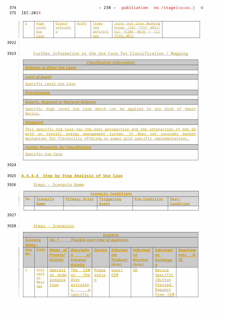
– 230 – publication no./stage(CDV,FDIS...) IEC:201X
General Remarks
General Remarks
A.4.9.2 Diagrams of Use CaseDiagram of Use Case
330
3658
3659
3660

Use Case Name: – 231 –Energy Flexibility Management
JWG1121 – Request for extra hot water using a heat pump
JWG1122 - Request for extra hot water using a heat pump and storage battery
331332

– 232 – publication no./stage(CDV,FDIS...) IEC:201X
JWG1123 - Request for extra hot water using a heat pump and storage battery
JWG1124 - Heat Pump Operation with Real-Time Tariff
JWG1125 - Heat pump and Photovoltaic Operation with Real-Time Tariff
333

Use Case Name: – 233 –Energy Flexibility Management
334335
3661

– 234 – publication no./stage(CDV,FDIS...) IEC:201X
A.4.9.3 Technical Details
Actors: People, Systems, Applications, Databases, the Power System, and Other Stakeholders
For the definition of this use case, the following architecture has been used as a basis.
Note that the actors in the above architecture are functional entities, which means that some of them may be part of the same physical device (e.g. CEM functionality may be part of a smart device, the smart meter might also encompass the smart metering gateway and CEM, etc…).
Please consider that the scope of this high level use does not require all actors shown on the figure above. Following table shows involved actors.
ActorsGrouping (Community) Group Description Actor Namesee Actor List
Actor Type see Actor List
Actor Description see Actor List
Further information specific to this Use Case
Customer Energy Manager
InternalThe CEM is a logical function optimising energy consumption and or production based on messages received from the grid, consumer’s settings and contracts, and devices minimum performance standards. The Customer Energy Manager collects messages sent to and received from connected devices; especially the in-home/building sector has to be mentioned. It can handle general or dedicated load and generation management commands and then forwards these to the connected devices. It provides vice versa information towards the “grid / market”. Note that multiple loads/generation resources can be combined in the CEM to be mutually controlled. When the CEM is integrated with communication functionalities it is called a Customer Energy Management System or CEMS
Smart ThermostatExternal
Using a Smart or programmable thermostat, one can adjust the temperature settings or the times turn on the heating or air-conditioning according to a pre-set schedule. Smart or programmable thermostats can store and repeat multiple daily settings (six or more temperature settings a day) that one can
CEM Smart Device*
Simple external consumer
display
Actor AEnergy
management gateway (EMG)
Smart Metering gateway (LNAP )
Smart meter functionalityActor B
Energy Management / Providing Flexibility (M490)
M441 architecture
Market communication
* e.g. HBES device, smart appliances, storage, generator, domestic charger for EV, complex display
Smart Grid Connection
Point
Functional metering reference architecture according the SM-CG (TR50572)
336
3662
36633664
3665
3666
3667366836693670367136723673

Use Case Name: – 235 –Energy Flexibility Management
manually override without affecting the rest of the daily or weekly program.
One can access it via the web using your tablet, smart phone or computer . The Smart Thermostat can be a device which is connected to the CEM and is programmed its settings from the CEM.
Smart deviceExternal
A smart device may be an appliance, generator or storage device (Local storage devices include direct and functional electricity storages such as electrochemical batteries, heat pumps and micro CHP such as fuel cells with heat buffers, air conditioning and cooling devices with thermal inertia, etc…) . The smart device can receive data directly from the grid, though an interface with the CEM and can react to commands and messages from the grid in an intelligent way.
Since the smart device is outside the scope of the SGCG, it must be seen as an external actor
Smart appliance (white goods)
ExternalAn example of a smart device is a smart white goods appliance which is an appliance that has the capability to act in response to a message from the grid and thereby optimize its behaviour towards the energy supply network. The message can be received from a utility or a third party energy service provider directly or via a home energy management system,
The message can be information like the cost of energy or the amount of available renewable energy, or it can be a Demand Respond message (delay load message or other related information) that the appliance must receive, interpret and react upon based on pre-set or active consumer input. The smart appliance is not guaranteed to respond, but will do so based on its status and user settings in order to ensure the expected performance.
The consumer has the ultimate control of the appliance and can override any specific mode (e.g. override a delay to allow immediate operation, limit delays to no more than a certain number of hours, or maintain a set room temperature).
Any appliance operation settings or modes shall be easy for an average, non-technical consumer to activate or implement.
Actor AExternal
External actor (Smart Grid Market Role) interacting with the system functions and components in the home or home automation network through the energy management communication channel.. Examples of such market roles are the Energy Provider, the Energy Services Provider, the aggregator, etc…
Actor BExternal
External actor (Smart Grid Market Role) interacting with the system functions and components in the home or home automation network through the metering communication channel. This actor is responsible for collecting metering data. Examples of such market roles are the DSO, metering company, etc.
UserExternal
The end customer who has acquired a smart device. The end customer is responsible for configuring and setting
337338

– 236 – publication no./stage(CDV,FDIS...) IEC:201X
operation mode of the Smart Device.
Triggering Event, Preconditions, Assumptions
Use Case ConditionsActor/System/Information/Contract
Triggering Event Pre-conditions Assumption
Tariff Information. CEM controls each appliance as programmed according to conditions of operating plan or CEM controls appliance by setting profile (e.g. temperature profile, Timer) defined according to conditions of operating plan
References
ReferencesNo. Referenc
es TypeReference Status Impact on
Use CaseOriginator / Organisation Link
1 Guideline Basic definitions and common procedures
Final Terms and definitions
SG-CG Sustainable Processes WG
ftp://ftp.cen.eu/EN/EuropeanStandardization/HotTopics/SmartGrids/Sustainable Processes.pdf
2 Technical Report
User Story and Sequence diagrams
Draft Major impact on Scenario
IEC TC57 / CLC TC205 / CLC /TC59x
-
3 Standard Use Case Template
Draft (FDIS)
Template desctription
IEC TC8 -
Further Information to the Use Case for Classification / Mapping
Classification InformationRelation to Other Use Cases Level of Depth
High Level Use Case
Prioritisation Generic, Regional or National Relation
High Level Use Case which can be applied to any kind of Smart Device. Once the regions agreed and confirmed correctness, that high level use case becomes a generic use case.
Viewpoint
This High Level Use Case has the User perspective and the interaction of the SD with an overall energy management system. It does not consider market mechanisms for flexibility offering or power
339
3674
3675
3676
3677
3678
3679

Use Case Name: – 237 –Energy Flexibility Management
grid specific implementations.
Further Keywords for Classification
Generic High Level Use Case
A.4.9.4 Step by Step Analysis of Use Case
Steps – Scenario Name
Scenario ConditionsNo. Scenario
NamePrimary Actor Triggering Event Pre-Condition Post-Condition
Steps – Scenarios
A.4.9.5 Information ExchangedInformation Exchanged
Name of Information (ID)
Description of Information Exchanged Requirements to information data
Simple Commands On/Off/Start/Stop/Pause/Resume/Abort/DimTimerA ir conditioner mode:
cooling down, heating up, mode 1-nW ind: auto, high, low, etcOther settings:
Such information is sensitive in a way that any modification might turn on or off a SD
Therefore, the communication data must be protected from misuse and external influences.
Temperature Profile A temperature profile defines the temperature set point over time (e.g. set point of each room temperature). A temperature profile might be split into multiple time slots. Such time slots have a fix amount of temperature to set a discrete temperature profile. A simple temperature profile will contain only one temperature value and its duration and there might be weekly temperature profiles each of which contains weekdays (Monday to Friday) / weekend profile.
Temperature Profile is sensitive in a way that any modification might affect drastic room temperature change.
Therefore, the communication data must be protected from misuse and external influences.
Tariff Information An external actor send some tariff information to the CEM which then further processes this information.
Storage Battery Commands
The storage battery system can feed in power to the local power network or can be charged. That information must be exchanged between the CEM and the SD.
A.4.9.6 Requirements (optional)
A.4.9.7 Common Terms and DefinitionsCommon Terms and Definitions
Term Definition
340341
3680
3681
3682
3683
3684
3685
3686
3687
3688

– 238 – publication no./stage(CDV,FDIS...) IEC:201X
A.4.9.8 Custom Information (optional)Custom Information (optional)
Key Value Refers to Section
342
3689
3690
3691

Use Case Name: – 239 –Energy Flexibility Management
A.4.10 HIGH LEVEL USE CASE (JWG 113x ) Log System Events
A.4.10.1 Description of the Use Case
Name of Use Case
Use Case IdentificationID Domain(s)/
Zone(s)Name of Use Case
JWG112x
Domain: Customer Premises, DER
Zones:Process, Field, Station
Use Cases that have various energy related devices like heat pumps and energy storage (taken from TR 62746-2 version 0.5.1).
Version Management
Version ManagementChanges / Version
Date Name Author(s) or Committee
Domain Expert
Area of Expertise / Domain / Role
Title/Changes Approval Statusdraft, for comments, for voting, f inal
0.1 Mar 07, 2014
Stephan Fertig (CLC TC59x WG7)
Home Appliances
Use Cases
Initial Draft (taken from TR 62746-2 version 0.5.1)
Draft
343344
36923693
3694
3695
3696
3697
3698

– 240 – publication no./stage(CDV,FDIS...) IEC:201X
Scope and Objectives of Use Case
Scope and Objectives of Use Case
Scope With proper management/instruction by CEM, Simple Device such as water heater, air conditioner and other appliances can act Smart. Events might cause state changes and system behavior might depend on direct interaction. This use cases describe different scenarios for system logging.
Objective(s) This Use Case defines the basic information exchange which is required to track evenets and system changes for various needs.
Related business case(s)
- Demand Response (DR)
- Demand Side Management (DSM)
Narrative of Use Case
Narrative of Use CaseShort descriptionThis use case describes various logging and status, event capturing scenarios.Complete description
345
3699
3700
3701

Use Case Name: – 241 –Energy Flexibility Management
JWG1131 – Display status and log information: Storage BatteryThis use case describes the request for status and logged information from the customer EMS controller to a storage battery controller and the display of the received information. The EMS controller requests status or log information from the Storage Battery Controller. After the information is received from the Storage Battery controller it is displayed by the EMS controller.
Log information may include measured cumulative charge/discharge electric power (Wh) and history of momentarily measured charge/discharge electric power (W), current (A), voltage (V) etc.
Status information may include cumulative charge/discharge electric power (Wh), remaining electric power (kWh, %) and momentary charge/discharge electric power (W), current (A), voltage (V), etc..
JWG1132 - Display status and log information: Heat PumpThis use case describes the request for status and logged information from the customer EMS controller to a heat pump controller and the display of the received information. The EMS controller requests status or log information from the heat pump controller. After the information is received from the heat pump controller it is displayed by the EMS controller.
Log information may include measured cumulative power consumption (Wh) and history of momentarily measured hot water temperature (C), hot water remaining value (l), electric power (W) etc.
Status information may include momentary hot water temperature (C), hot water remaining value (l), electric power (W)) to the Customer EMS Controller etc.
JWG1133 - Display status and log information: Fuel CellThis use case describes the request for status and logged information from the customer EMS controller to a fuel cell controller and the display of the received information. The EMS controller requests status or log information from the fuel cell controller. After the information is received from the fuel cell controller it is displayed by the EMS controller.
Log information may include measured cumulative generated electric power (Wh), measured momentary gas consumption (m3), measured cumulative gas consumption (m3) and history of momentarily measured hot water temperature (C), heat quantity in the water tank (MJ), hot water remaining value (L), generated electric power (W)
Status information may include momentary hot water temperature (C), heat quantity in the water tank (MJ), hot water remaining value (L), generated electric power (W), measured cumulative generated electric power (Wh), measured momentary gas consumption (m3), measured cumulative gas consumption (m3).
JWG1134 - Display status and log information: PhotovoltaicThis use case describes the request for status and logged information from the customer EMS controller to a PV controller and the display of the received information. The EMS controller requests status or log information from the PV controller. After the information is received from the PV controller it is displayed by the EMS controller.
Log information may include measured cumulative generated power (Wh), measured cumulative exported power (Wh) and history of momentarily measured generated power (W), measured momentary exported power (W) etc.
Status information may include momentary generated power (W), momentary exported power (W), measured cumulative generated power (Wh), measured cumulative exported power (Wh) etc.
346347
3702

– 242 – publication no./stage(CDV,FDIS...) IEC:201X
General Remarks
General Remarks
A.4.10.2 Diagrams of Use CaseDiagram of Use Case
348
3703
3704
3705

Use Case Name: – 243 –Energy Flexibility Management
JWG1131 – Display status and log information: Storage Battery
JWG1132 - Display status and log information: Heat Pump
JWG1133 - Display status and log information: Fuel Cell
349350

– 244 – publication no./stage(CDV,FDIS...) IEC:201X
JWG1134 - Display status and log information: Photovoltaic
351
3706

Use Case Name: – 245 –Energy Flexibility Management
A.4.10.3 Technical Details
Actors: People, Systems, Applications, Databases, the Power System, and Other Stakeholders
For the definition of this use case, the following architecture has been used as a basis.
Note that the actors in the above architecture are functional entities, which means that some of them may be part of the same physical device (e.g. CEM functionality may be part of a smart device, the smart meter might also encompass the smart metering gateway and CEM, etc…).
Please consider that the scope of this high level use does not require all actors shown on the figure above. Following table shows involved actors.
ActorsGrouping (Community) Group Description Actor Namesee Actor List
Actor Type see Actor List
Actor Description see Actor List
Further information specific to this Use Case
Customer Energy Manager
InternalThe CEM is a logical function optimising energy consumption and or production based on messages received from the grid, consumer’s settings and contracts, and devices minimum performance standards. The Customer Energy Manager collects messages sent to and received from connected devices; especially the in-home/building sector has to be mentioned. It can handle general or dedicated load and generation management commands and then forwards these to the connected devices. It provides vice versa information towards the “grid / market”. Note that multiple loads/generation resources can be combined in the CEM to be mutually controlled. When the CEM is integrated with communication functionalities it is called a Customer Energy Management System or CEMS
Smart ThermostatExternal
Using a Smart or programmable thermostat, one can adjust the temperature settings or the times turn on the heating or air-conditioning according to a pre-set schedule. Smart or programmable thermostats can store and repeat multiple daily settings (six or more temperature settings a day) that one can
CEM Smart Device*
Simple external consumer
display
Actor AEnergy
management gateway (EMG)
Smart Metering gateway (LNAP )
Smart meter functionalityActor B
Energy Management / Providing Flexibility (M490)
M441 architecture
Market communication
* e.g. HBES device, smart appliances, storage, generator, domestic charger for EV, complex display
Smart Grid Connection
Point
Functional metering reference architecture according the SM-CG (TR50572)
352353
3707
37083709
3710
3711
3712371337143715371637173718

– 246 – publication no./stage(CDV,FDIS...) IEC:201X
manually override without affecting the rest of the daily or weekly program.
One can access it via the web using your tablet, smart phone or computer . The Smart Thermostat can be a device which is connected to the CEM and is programmed its settings from the CEM.
Smart deviceExternal
A smart device may be an appliance, generator or storage device (Local storage devices include direct and functional electricity storages such as electrochemical batteries, heat pumps and micro CHP such as fuel cells with heat buffers, air conditioning and cooling devices with thermal inertia, etc…) . The smart device can receive data directly from the grid, though an interface with the CEM and can react to commands and messages from the grid in an intelligent way.
Since the smart device is outside the scope of the SGCG, it must be seen as an external actor
Smart appliance (white goods)
ExternalAn example of a smart device is a smart white goods appliance which is an appliance that has the capability to act in response to a message from the grid and thereby optimize its behaviour towards the energy supply network. The message can be received from a utility or a third party energy service provider directly or via a home energy management system,
The message can be information like the cost of energy or the amount of available renewable energy, or it can be a Demand Respond message (delay load message or other related information) that the appliance must receive, interpret and react upon based on pre-set or active consumer input. The smart appliance is not guaranteed to respond, but will do so based on its status and user settings in order to ensure the expected performance.
The consumer has the ultimate control of the appliance and can override any specific mode (e.g. override a delay to allow immediate operation, limit delays to no more than a certain number of hours, or maintain a set room temperature).
Any appliance operation settings or modes shall be easy for an average, non-technical consumer to activate or implement.
Actor AExternal
External actor (Smart Grid Market Role) interacting with the system functions and components in the home or home automation network through the energy management communication channel.. Examples of such market roles are the Energy Provider, the Energy Services Provider, the aggregator, etc…
Actor BExternal
External actor (Smart Grid Market Role) interacting with the system functions and components in the home or home automation network through the metering communication channel. This actor is responsible for collecting metering data. Examples of such market roles are the DSO, metering company, etc.
UserExternal
The end customer who has acquired a smart device. The end customer is responsible for configuring and setting
354

Use Case Name: – 247 –Energy Flexibility Management
operation mode of the Smart Device.
Triggering Event, Preconditions, Assumptions
Use Case ConditionsActor/System/Information/Contract
Triggering Event Pre-conditions Assumption
Tariff Information. CEM controls each appliance as programmed according to conditions of operating plan or CEM controls appliance by setting profile (e.g. temperature profile, Timer) defined according to conditions of operating plan
References
ReferencesNo. Referenc
es TypeReference Status Impact on
Use CaseOriginator / Organisation Link
1 Guideline Basic definitions and common procedures
Final Terms and definitions
SG-CG Sustainable Processes WG
ftp://ftp.cen.eu/EN/EuropeanStandardization/HotTopics/SmartGrids/Sustainable Processes.pdf
2 Technical Report
User Story and Sequence diagrams
Draft Major impact on Scenario
IEC TC57 / CLC TC205 / CLC /TC59x
-
3 Standard Use Case Template
Draft (FDIS)
Template desctription
IEC TC8 -
Further Information to the Use Case for Classification / Mapping
Classification InformationRelation to Other Use Cases Level of Depth
High Level Use Case
Prioritisation Generic, Regional or National Relation
High Level Use Case which can be applied to any kind of Smart Device. Once the regions agreed and confirmed correctness, that high level use case becomes a generic use case.
Viewpoint
This High Level Use Case has the User perspective and the interaction of the SD with an overall energy management system. It does not consider market mechanisms for flexibility offering or power
355356
3719
3720
3721
3722
3723
3724

– 248 – publication no./stage(CDV,FDIS...) IEC:201X
grid specific implementations.
Further Keywords for Classification
Generic High Level Use Case
A.4.10.4 Step by Step Analysis of Use Case
Steps – Scenario Name
Scenario ConditionsNo. Scenario
NamePrimary Actor Triggering Event Pre-Condition Post-Condition
Steps – Scenarios
A.4.10.5 Information ExchangedInformation Exchanged
Name of Information (ID)
Description of Information Exchanged Requirements to information data
Status Information and Events
Events that indicate system or Smart Device behaviour might be exchanged. In general, system relevant information shall be exchanged.
Such information is sensitive in a way that any modification might customer specific and confidential information. Therefore, the communication data must be protected from misuse and external influences.
A.4.10.6 Requirements (optional)
A.4.10.7 Common Terms and DefinitionsCommon Terms and Definitions
Term Definition
A.4.10.8 Custom Information (optional)Custom Information (optional)
Key Value Refers to Section
357
3725
3726
3727
3728
3729
3730
3731
3732
3733
3734
3735
3736

Use Case Name: – 249 –Energy Flexibility Management
A.4.11 JWG1200-HLUC Flexible start of a Smart Device (SD)
A.4.11.1 Description of the Use Case
Name of Use Case
Use Case IdentificationID Domain(s)/
Zone(s)Name of Use Case
JWG1100
Domain: Customer Premises, DER
Zones:Process, Field, Station
SD consumes / generates energy on a flexible basis (High Level Use Case or Generic Use Case)
Version Management
Version ManagementChanges / Version
Date Name Author(s) or Committee
Domain Expert
Area of Expertise / Domain / Role
Title/Changes Approval Statusdraft, for comments, for voting, f inal
0.1 Nov.04, 2013
Stephan Fertig (CLC TC59x WG7)
Editor Initial Draft Draft
0.2 Dec.06, 201
Stephan Fertig (CLC TC59x WG7)
Editor Updated Version after CLC TC59x discussions
Draft
0.3 Jan.06, 2014
Stephan Fertig (CLC TC59x WG7)
Editor Update HLUC to fit Joint Use Case Workshop description
Draft
0.4 Mar 07, 2014
Stephan Fertig (CLC TC59x WG7)
Editor Added JWG-ID Draft
358359
37373738
3739
3740
3741
3742
3743

– 250 – publication no./stage(CDV,FDIS...) IEC:201X
Scope and Objectives of Use Case
Scope and Objectives of Use Case
Scope In some cases Smart Devices provide flexibility towards their time. The device can manage its flexible running times by itself and communicates them to the CEM on a negotiation basis.
Utilizing flexibility by a CEM must be negotiated and confirmed with the smart device. The flexible operation of a Smart Device does not imply a specific optimization strategy. It depends on the control algorithm which the customer defines for its Smart Device and the CEM.
The scope of that High Level Use Case deals with the basic information exchange between a Smart Device and the CEM to allow a flexible start. Also it covers the information exchange on the energy consumption during operation to allow an energy scheduling within the CEM.
Objective(s) This use case defines the basic information which is required to offer flexible start of Smart Devices.
There are various optimization targets possible for setting a flexible start time.
Related business case(s)
- Demand Response (DR)
- Demand Side Management (DSM)
Narrative of Use Case
Narrative of Use CaseShort descriptionThe User activates a specific profile on the Smart Device that allows a flexible start. The Smart Device then starts a negotiation process with the CEM to find the most suitable start time. The interaction between the SD and the CEM does not require user interaction and operates autonomously. The SD fulfils the job according to the activated profile and might ask the user for final confirmation. After job completion the end customer might get notified on successful or failed commissioning.
A Smart Device might have two basic operational modes:
- Power Consumption by using electricty
- Power Producing by generating electricity
Complete descriptionThe User activates a specific action profile on the Smart Device. The Smart Device then negotiates a start time with the CEM based on the selected specifification. Such specification might include user specific requirements like pre-defined end-time, maximum energy consumption, or something else and device specific capabilities. Such a profile can be very simple and defines a setting for a specific purpose.
The interaction between the SD and the CEM does not require user interaction and operates autonomously. It is up to the SD to find the best possible solution according to the user defined operational mode. The SD visualizes relevant information to the User if possible and starts action in cooperation with the CEM. Once the User activates a profile on flexible start time of a smart device, the User hands over the control to the CEM or Smart Device.
The SD fulfils the job according to the activated profile of the user and notifies the User on successful or failed commissioning. A notification and visualization method of relevant information varies on the appliances that are used.
This Use Case comprises three primary use cases:
4. JWG1101 : SD informs CEM about flexible start
The Smart Device informs the CEM about its flexibility and limitations.
360
3744
3745
3746
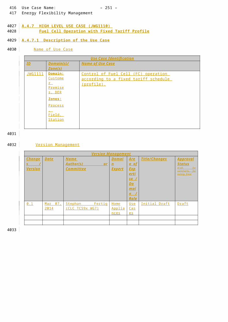
Use Case Name: – 251 –Energy Flexibility Management
5. JWG1102 : CEM informs SD about starting time
The CEM coordinates an optimized starting according to the selected operational strategy. It might require consideration of more than one smart device for calculating a suitable start time.
6. JWG 1103 : CEM informs SD about slot shift
The calculated start which had been sent to the Smart Device by the CEM requires an update. There might be a change in the environment which requires the CEM to recalculate a new start time (within the pre-defined limits of the affected Smart Devices).
General Remarks
General RemarksThis High Level Use Case or Generic Use Case considers smart devices like home appliances (white goods, brown goods and consumer electronics).
Any communication between SD and CEM must provide acknowledge handling on application level and basic failure detection. A broken communication link shall not lead to an unsecure and critical situation. Therefore, Smart Devices must provide device specific fail-safe mechanisms to prevent danger from the customer (e.g. a cleaning process of an oven with very high temperatures shall not lead to a critical situation in the home if communication fails).
A.4.11.2 Diagrams of Use CaseDiagram of Use Case
See detailed description of use cases
361362
3747
3748
3749
3750
3751

– 252 – publication no./stage(CDV,FDIS...) IEC:201X
A.4.11.3 Technical Details
Actors: People, Systems, Applications, Databases, the Power System, and Other Stakeholders
For the definition of this use case, the following architecture has been used as a basis.
Note that the actors in the above architecture are functional entities, which means that some of them may be part of the same physical device (e.g. CEM functionality may be part of a smart device, the smart meter might also encompass the smart metering gateway and CEM, etc…).
Please consider that the scope of this high level use does not require all actors shown on the figure above. Following table shows involved actors.
ActorsGrouping (Community) Group Description Actor Namesee Actor List
Actor Type see Actor List
Actor Description see Actor List
Further information specific to this Use Case
Customer Energy Manager
InternalThe CEM is a logical function optimising energy consumption and or production based on messages received from the grid, consumer’s settings and contracts, and devices minimum performance standards. The Customer Energy Manager collects messages sent to and received from connected devices; especially the in-home/building sector has to be mentioned. It can handle general or dedicated load and generation management commands and then forwards these to the connected devices. It provides vice versa information towards the “grid / market”. Note that multiple loads/generation resources can be combined in the CEM to be mutually controlled.
When the CEM is integrated with communication functionalities it is called a Customer Energy Management System or CEMS
Smart deviceExternal
A smart device may be an appliance, generator or storage device (Local storage devices include direct and functional electricity storages such as electrochemical batteries, heat pumps and micro CHP such as fuel cells with heat buffers,
CEM Smart Device*
Simple external consumer
display
Actor AEnergy
management gateway (EMG)
Smart Metering gateway (LNAP )
Smart meter functionalityActor B
Energy Management / Providing Flexibility (M490)
M441 architecture
Market communication
* e.g. HBES device, smart appliances, storage, generator, domestic charger for EV, complex display
Smart Grid Connection
Point
Functional metering reference architecture according the SM-CG (TR50572)
363
3752
37533754
3755
3756
3757375837593760376137623763

Use Case Name: – 253 –Energy Flexibility Management
air conditioning and cooling devices with thermal inertia, etc…) . The smart device can receive data directly from the grid, though an interface with the CEM and can react to commands and messages from the grid in an intelligent way.
Since the smart device is outside the scope of the SGCG, it must be seen as an external actor
Smart appliance (white goods)
ExternalAn example of a smart device is a smart white goods appliance which is an appliance that has the capability to act in response to a message from the grid and thereby optimize its behaviour towards the energy supply network. The message can be received from a utility or a third party energy service provider directly or via a home energy management system,
The message can be information like the cost of energy or the amount of available renewable energy, or it can be a Demand Respond message (delay load message or other related information) that the appliance must receive, interpret and react upon based on pre-set or active consumer input. The smart appliance is not guaranteed to respond, but will do so based on its status and user settings in order to ensure the expected performance.
The consumer has the ultimate control of the appliance and can override any specific mode (e.g. override a delay to allow immediate operation, limit delays to no more than a certain number of hours, or maintain a set room temperature).
Any appliance operation settings or modes shall be easy for an average, non-technical consumer to activate or implement.
Actor AExternal
External actor (Smart Grid Market Role) interacting with the system functions and components in the home or home automation network through the energy management communication channel.. Examples of such market roles are the Energy Provider, the Energy Services Provider, the aggregator, etc…
Actor BExternal
External actor (Smart Grid Market Role) interacting with the system functions and components in the home or home automation network through the metering communication channel. This actor is responsible for collecting metering data. Examples of such market roles are the DSO, metering company, etc.
UserExternal
The end customer who has acquired a smart device. The end customer is responsible for configuring and setting operation mode of the Smart Device.
364365
3764

– 254 – publication no./stage(CDV,FDIS...) IEC:201X
Triggering Event, Preconditions, Assumptions
Use Case ConditionsActor/System/Information/Contract
Triggering Event Pre-conditions Assumption
SD
Activation Message SD is active and operational.
User has created or selected a profile before creating the event. SD starts negotiations with CEM based on the profile.
References
ReferencesNo. Referenc
es TypeReference Status Impact on
Use CaseOriginator / Organisation Link
1 Guideline Basic definitions and common procedures
Final Terms and definitions
SG-CG Sustainable Processes WG
ftp://ftp.cen.eu/EN/EuropeanStandardization/HotTopics/SmartGrids/Sustainable Processes.pdf
2 Technical Report
User Story and Sequence diagrams
Draft Major impact on Scenario
IEC TC57 / CLC TC205 / CLC /TC59x
-
3 Standard Use Case Template
Draft (FDIS)
Template desctription
IEC TC8 -
Further Information to the Use Case for Classification / Mapping
Classification InformationRelation to Other Use Cases Level of Depth
High Level Use Case
Prioritisation Generic, Regional or National Relation
Generic High Level Use Case which can be applied to any kind of Smart Device.
Viewpoint
This High Level Use Case has the User perspective and the interaction of the SD with an overall energy management system. It does not consider market mechanisms for flexibility offering or power grid specific implementations.
Further Keywords for Classification
Generic High Level Use Case
366
3765
3766
3767
3768
3769
3770

Use Case Name: – 255 –Energy Flexibility Management
A.4.11.4 Step by Step Analysis of Use Case
Steps – Scenario Name
Scenario ConditionsNo. Scenario
NamePrimary Actor Triggering Event Pre-Condition Post-Condition
Steps – Scenarios
Scenario JWG1100 Flexible Start SDScenario Name :
No. 1 - Flexible start time of appliance
Step No.
Event Name of Process/ Activity
Description of Process/ Activity
Service Information Producer (Actor)
Information Receiver (Actor)
Information Requirements , R-ID Exchanged
1 - Preparation User prepares SD for operation.
Preparation
User SD Device Specific (Door Closed, Water tap connected, Gas burner connected, electrical heating connected, …)
2 - Operation mode preparation
User enters settings for operational mode
Profile Generation/Selection
User SD Device and Customer Specific Data
3 Activation Message
Operation Mode Activation
Pre-defined or manually entered setting become active on SD
Service Activation
User SD General Device Data (Activation)
4 SD Notification
SD informs CEM
SD sends activation profile to CEM.
Notification of User request to CEM
SD CEM Profile
5 Negotiation
CEM/SD Negotiation
CEM and SD negotiate on flexible start time
Schedule Planning
SD/CEM CEM/SD Device and Customer Specific Data
6 User Information
Visualization
SD notifies the User on the schedule
Information delivery
SD User Profile
367368
3771
3772
3773
3774
3775
3776
3777
3778

– 256 – publication no./stage(CDV,FDIS...) IEC:201X
A.4.11.5 Information ExchangedInformation Exchanged
Name of Information (ID)
Description of Information Exchanged Requirements to information data
Device Specific Data (DSD)
Device specific data can be classified to each product family like dish washer, washing machine, heating unit, etc.
This set of data is specific to the category of the SD. A SD might have multiple device specific data sets when combining multiple features.
Such information is sensitive in a way that any modification might change certain behaviour of a SD. That is crucial for CEM-SD negotiations.
Therefore, the communication must be protected from misuse and external influences.
Customer Specific Data (CSD)
The user who operates might be able to create a profile for customer specific information. Depending on the SD the data set might contain SLAs with energy providers, comfort settings, Customer habits, etc.
A SD can maintain one or more customer specific data sets.
CSD contains sensitive information. Such a data set might contain SLAs and privacy relevant information. Therefore, such information must be handled with care and shall be accessible to relevant actors only. That includes, that the CEM shall not be able to access contract specific information which belong to third party service providers.
General Device Data (GDD)
Common information which is required from each SD like an ID, communication address, status information, etc.
This set of data is not specific to white, brown, or consumer goods.
GDD provide common standardized functionalities which are the lower limit for enabling
Such information is sensitive in a way that any modification might turn on or off a SD.
Therefore, the communication must be protected from misuse and external influences.
Energy Profile An energy profile defines characteristics towards s specific operational mode which is applicable to the Smart Device.
Such information can be used for power consumption but also power generation.
The energy profile does not contain sensitive data in a way that it gives indication on the used Energy for a specific operational mode.
A.4.11.6 Requirements (optional)
369
3779
3780
3781

Use Case Name: – 257 –Energy Flexibility Management
A.4.11.7 Common Terms and DefinitionsCommon Terms and Definitions
Term Definition
Energy Profile An energy profile defines the power consumption/generation over time. The power might vary on the smart device which will be captured and visualized by the energy profile.
An energy profile might be split into multiple time slots. Such time slots have a fix amount of power to get a discrete power consumption/generation profile. A simple energy profile will contain only one power value and its duration.
A.4.11.8 Custom Information (optional)Custom Information (optional)
Key Value Refers to Section
370371
3782
3783
3784

– 258 – publication no./stage(CDV,FDIS...) IEC:201X
A.4.12 HIGH LEVEL USE CASE (JWG 120x ) Provide local power managing capabilities.
A.4.12.1 Description of the Use Case
Name of Use Case
Use Case IdentificationID Domain(s)/
Zone(s)Name of Use Case
JWG113x
Domain: Customer Premises, DER
Zones:Process, Field, Station
Local energy management (taken from TR 62746-2 version 0.5.1).
Version Management
Version ManagementChanges / Version
Date Name Author(s) or Committee
Domain Expert
Area of Expertise / Domain / Role
Title/Changes Approval Statusdraft, for comments, for voting, f inal
0.1 Mar 07, 2014
Stephan Fertig (CLC TC59x WG7)
Home Appliances
Use Cases
Initial Draft (taken from TR 62746-2 version 0.5.1)
Draft
Scope and Objectives of Use Case
Scope and Objectives of Use Case
Scope Local energy management can be implemented when combining loads with generators. There are various power generation devices possible and and power consuming device represnets a load.
Objective(s) This Use Case defines the basic information exchange which is required to provide local energy management.
Related business case(s)
- Demand Response (DR)
- Demand Side Management (DSM)
Narrative of Use Case
Narrative of Use CaseShort description Complete description
372
37853786
3787
3788
3789
3790
3791
3792
3793
3794

Use Case Name: – 259 –Energy Flexibility Management
JWG1201 – Exported power control from Photovoltaic using a loadThis use case describes the operation of the PV and EMS controllers and loads when the PV is being used to export power and the energy supplier requests a reduction of exported power. The energy supplier monitors the exported power and requests the home customer's EMS to reduce the exported power level. The EMS responds by using a proportion of the PV output to power loads which it turns on.
JWG1202 - Exported power control from Fuel Cell using a loadThis use case describes the operation of the fuel cell and EMS controllers and loads when the fuel cell is being used to export power and the energy supplier requests a reduction of exported power. The energy supplier monitors the exported power and requests the home customer's EMS to reduce the exported power level. The EMS responds by using a proportion of the fuel cell output to power loads which it turns on.
JWG1203 - Exported power control from PV using Heat PumpThis use case describes the operation of the PV, EMS and heat pump controllers when the PV is being used to export power and the energy supplier requests a reduction of exported power. The energy supplier monitors the exported power and requests the home customer's EMS to reduce the exported power level. The EMS responds by using a proportion of the PV output to power the heat pump, by requesting the heat pump controller to either increase operating power or turn on and optionally requesting the heat pump controller to modify thermostat settings.
JWG1204 - Exported power control from PV using Heat Pump and Load(s)This use case describes the operation of the PV, EMS and heat pump controllers when the PV is being used to export power and the energy supplier requests a reduction of exported power. The energy supplier monitors the exported power and requests the home customer's EMS to reduce the exported power level. The EMS responds by using a proportion of the PV output to power the heat pump and by optionally requesting the heat pump controller to modify thermostat settings, additionally requesting that one or more loads turn on in the case that the heat pump storage tank is already at capacity.
General Remarks
General Remarks
A.4.12.2 Diagrams of Use CaseDiagram of Use Case
373374
3795
3796
3797
3798

– 260 – publication no./stage(CDV,FDIS...) IEC:201X
JWG1201 – Exported power control from Photovoltaic using a load
JWG1202 - Exported power control from Fuel Cell using a load
JWG1203 - Exported power control from PV using Heat Pump
375
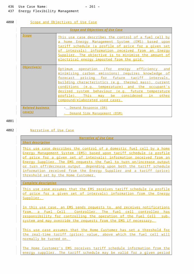
Scenario 10_1 (HP+PV) : PV and HP operation according to control over reverse power flow
Energy SupplierEnergy
Management System
Heat Pump Controller
Exported power reduction requestTurn on Heat Pump request ()
Status ReportsGenerate
PV Controller
Status message (success/failure)
Thermostatic radiator valve
Monitor exported power level and quality
opt Room Temperature set request ()
Status message (success/failure)
Room Temperature set request ()
Status message (success/failure)
WGSP 2121 Specific Use Case: Exported power control from photovoltaic using a heat pump
Increa se Ope ra t ing Power o rTurn on Hea t Pump reques t ( )
Use Case Name: – 261 –Energy Flexibility Management
JWG1204 - Exported power control from PV using Heat Pump and Load(s)
376377

– 262 – publication no./stage(CDV,FDIS...) IEC:201X
A.4.12.3 Technical Details
Actors: People, Systems, Applications, Databases, the Power System, and Other Stakeholders
For the definition of this use case, the following architecture has been used as a basis.
Note that the actors in the above architecture are functional entities, which means that some of them may be part of the same physical device (e.g. CEM functionality may be part of a smart device, the smart meter might also encompass the smart metering gateway and CEM, etc…).
Please consider that the scope of this high level use does not require all actors shown on the figure above. Following table shows involved actors.
ActorsGrouping (Community) Group Description Actor Namesee Actor List
Actor Type see Actor List
Actor Description see Actor List
Further information specific to this Use Case
Customer Energy Manager
InternalThe CEM is a logical function optimising energy consumption and or production based on messages received from the grid, consumer’s settings and contracts, and devices minimum performance standards. The Customer Energy Manager collects messages sent to and received from connected devices; especially the in-home/building sector has to be mentioned. It can handle general or dedicated load and generation management commands and then forwards these to the connected devices. It provides vice versa information towards the “grid / market”. Note that multiple loads/generation resources can be combined in the CEM to be mutually controlled. When the CEM is integrated with communication functionalities it is called a Customer Energy Management System or CEMS
Smart ThermostatExternal
Using a Smart or programmable thermostat, one can adjust the temperature settings or the times turn on the heating or air-conditioning according to a pre-set schedule. Smart or programmable thermostats can store and repeat multiple daily settings (six or more temperature settings a day) that one can
CEM Smart Device*
Simple external consumer
display
Actor AEnergy
management gateway (EMG)
Smart Metering gateway (LNAP )
Smart meter functionalityActor B
Energy Management / Providing Flexibility (M490)
M441 architecture
Market communication
* e.g. HBES device, smart appliances, storage, generator, domestic charger for EV, complex display
Smart Grid Connection
Point
Functional metering reference architecture according the SM-CG (TR50572)
378
3799
38003801
3802
3803
3804380538063807380838093810

Use Case Name: – 263 –Energy Flexibility Management
manually override without affecting the rest of the daily or weekly program.
One can access it via the web using your tablet, smart phone or computer . The Smart Thermostat can be a device which is connected to the CEM and is programmed its settings from the CEM.
Smart deviceExternal
A smart device may be an appliance, generator or storage device (Local storage devices include direct and functional electricity storages such as electrochemical batteries, heat pumps and micro CHP such as fuel cells with heat buffers, air conditioning and cooling devices with thermal inertia, etc…) . The smart device can receive data directly from the grid, though an interface with the CEM and can react to commands and messages from the grid in an intelligent way.
Since the smart device is outside the scope of the SGCG, it must be seen as an external actor
Smart appliance (white goods)
ExternalAn example of a smart device is a smart white goods appliance which is an appliance that has the capability to act in response to a message from the grid and thereby optimize its behaviour towards the energy supply network. The message can be received from a utility or a third party energy service provider directly or via a home energy management system,
The message can be information like the cost of energy or the amount of available renewable energy, or it can be a Demand Respond message (delay load message or other related information) that the appliance must receive, interpret and react upon based on pre-set or active consumer input. The smart appliance is not guaranteed to respond, but will do so based on its status and user settings in order to ensure the expected performance.
The consumer has the ultimate control of the appliance and can override any specific mode (e.g. override a delay to allow immediate operation, limit delays to no more than a certain number of hours, or maintain a set room temperature).
Any appliance operation settings or modes shall be easy for an average, non-technical consumer to activate or implement.
Actor AExternal
External actor (Smart Grid Market Role) interacting with the system functions and components in the home or home automation network through the energy management communication channel.. Examples of such market roles are the Energy Provider, the Energy Services Provider, the aggregator, etc…
Actor BExternal
External actor (Smart Grid Market Role) interacting with the system functions and components in the home or home automation network through the metering communication channel. This actor is responsible for collecting metering data. Examples of such market roles are the DSO, metering company, etc.
UserExternal
The end customer who has acquired a smart device. The end customer is responsible for configuring and setting
379380

– 264 – publication no./stage(CDV,FDIS...) IEC:201X
operation mode of the Smart Device.
Triggering Event, Preconditions, Assumptions
Use Case ConditionsActor/System/Information/Contract
Triggering Event Pre-conditions Assumption
References
ReferencesNo. Referenc
es TypeReference Status Impact on
Use CaseOriginator / Organisation Link
1 Guideline Basic definitions and common procedures
Final Terms and definitions
SG-CG Sustainable Processes WG
ftp://ftp.cen.eu/EN/EuropeanStandardization/HotTopics/SmartGrids/Sustainable Processes.pdf
2 Technical Report
User Story and Sequence diagrams
Draft Major impact on Scenario
IEC TC57 / CLC TC205 / CLC /TC59x
-
3 Standard Use Case Template
Draft (FDIS)
Template desctription
IEC TC8 -
Further Information to the Use Case for Classification / Mapping
Classification InformationRelation to Other Use Cases Level of Depth
High Level Use Case
Prioritisation Generic, Regional or National Relation
High Level Use Case which can be applied to any kind of Smart Device. Once the regions agreed and confirmed correctness, that high level use case becomes a generic use case.
Viewpoint
This High Level Use Case has the User perspective and the interaction of the SD with an overall energy management system. It does not consider market mechanisms for flexibility offering or power grid specific implementations.
Further Keywords for Classification
Generic High Level Use Case
A.4.12.4 Step by Step Analysis of Use Case
Steps – Scenario Name
Scenario Conditions
381
3811
3812
3813
3814
3815
3816
3817
3818
3819

Use Case Name: – 265 –Energy Flexibility Management
No. Scenario Name
Primary Actor Triggering Event Pre-Condition Post-Condition
Steps – Scenarios
A.4.12.5 Information ExchangedInformation Exchanged
Name of Information (ID)
Description of Information Exchanged Requirements to information data
Status Information and Events
Events that indicate system or Smart Device behaviour might be exchanged. In general, system relevant information shall be exchanged.
Such information is sensitive in a way that any modification might customer specific and confidential information. Therefore, the communication data must be protected from misuse and external influences.
Simple Commands On/Off/Start/Stop/Pause/Resume/Abort/DimTimerA ir conditioner mode:
cooling down, heating up, mode 1-nW ind: auto, high, low, etcOther settings:
Such information is sensitive in a way that any modification might turn on or off a SD
Therefore, the communication data must be protected from misuse and external influences.
A.4.12.6 Requirements (optional)
A.4.12.7 Common Terms and DefinitionsCommon Terms and Definitions
Term Definition
A.4.12.8 Custom Information (optional)Custom Information (optional)
Key Value Refers to Section
382383
3820
3821
3822
3823
3824
3825
3826
3827
3828
3829
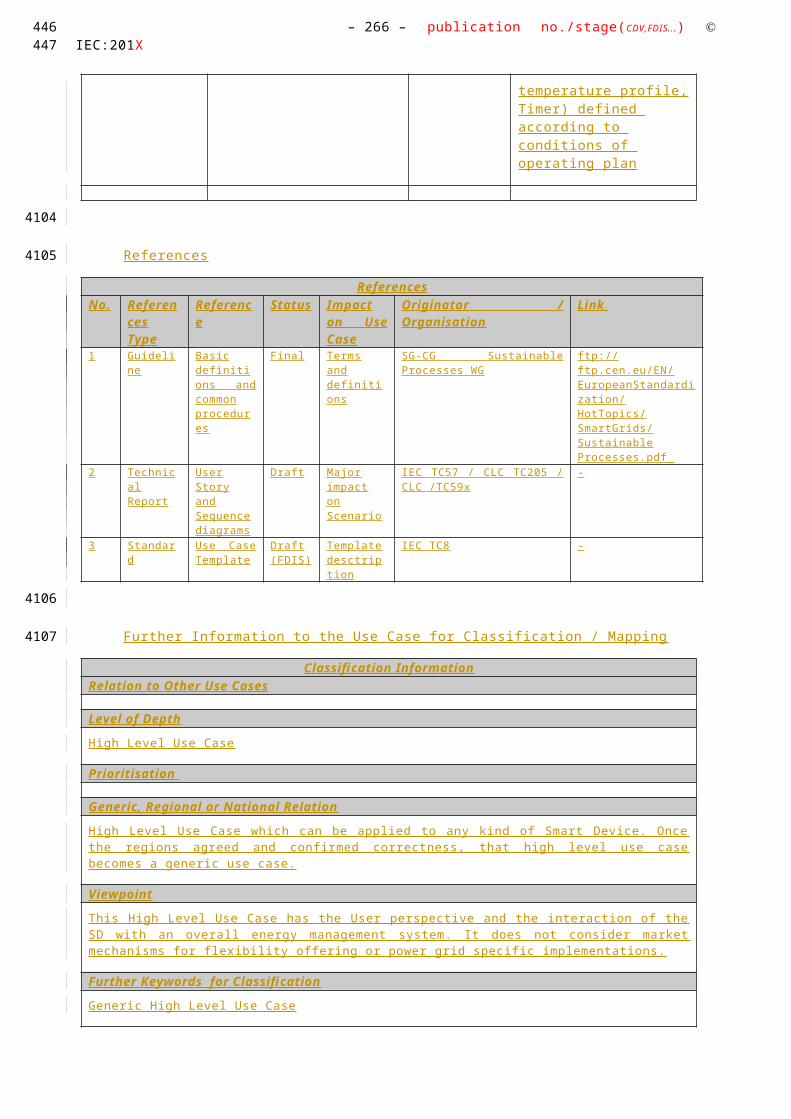
– 266 – publication no./stage(CDV,FDIS...) IEC:201X
A.4.13 HIGH LEVEL USE CASE (JWG 121x ) Provide local power managing capabilities.
A.4.13.1 Description of the Use Case
Name of Use Case
Use Case IdentificationID Domain(s)/
Zone(s)Name of Use Case
JWG121x
Domain: Customer Premises, DER
Zones:Process, Field, Station
Local energy management (taken from TR 62746-2 version 0.5.1).
Version Management
Version ManagementChanges / Version
Date Name Author(s) or Committee
Domain Expert
Area of Expertise / Domain / Role
Title/Changes Approval Statusdraft, for comments, for voting, f inal
0.1 Mar 07, 2014
Stephan Fertig (CLC TC59x WG7)
Home Appliances
Use Cases
Initial Draft (taken from TR 62746-2 version 0.5.1)
Draft
Scope and Objectives of Use Case
Scope and Objectives of Use Case
Scope Providing local energy management to the power grid can be implemented with various energy devices.This Use Case captures various energy sources.
Objective(s) This Use Case defines the basic information exchange which is required to provide local energy to the grid.
Related business case(s)
- Demand Response (DR)
- Demand Side Management (DSM)
Narrative of Use Case
Narrative of Use CaseShort description Complete description
384
38303831
3832
3833
3834
3835
3836
3837
3838
3839

Use Case Name: – 267 –Energy Flexibility Management
JWG1211 – Exported power control from Fuel CellThis use case describes the operation of the fuel cell and EMS controllers when the fuel cell is being used to export power and the energy supplier requests a reduction of exported power. The energy supplier monitors the exported power and requests the home customer's EMS to reduce the exported power level. The EMS responds by requesting the fuel cell controller to turn off the fuel cell.
JWG1212 - Exported power control from a photovoltaic systemThis use case describes the operation of the PV and EMS controllers when the PV system is being used to export power and the energy supplier requests a reduction of exported power. The energy supplier monitors the exported power and requests the home customer's EMS to reduce the exported power level. The EMS responds by requesting the PV controller to turn off the PV system.
JWG1213 - Exported power control from fuel cell and photovoltaic systemsThis use case describes the operation of the fuel cell, PV and EMS controllers when fuel cell and PV systems are being used to export power and the energy supplier requests a reduction of exported power. The energy supplier monitors the exported power and requests the home customer's EMS to reduce the exported power level. The EMS responds by requesting the fuel cell and PV controllers to turn off the PV system.
General Remarks
General Remarks
A.4.13.2 Diagrams of Use CaseDiagram of Use Case
385386
3840
3841
3842
3843

– 268 – publication no./stage(CDV,FDIS...) IEC:201X
JWG1211 – Exported power control from Fuel Cell
JWG1212 - Exported power control from a photovoltaic system
JWG1213 - Exported power control from fuel cell and photovoltaic systems
387
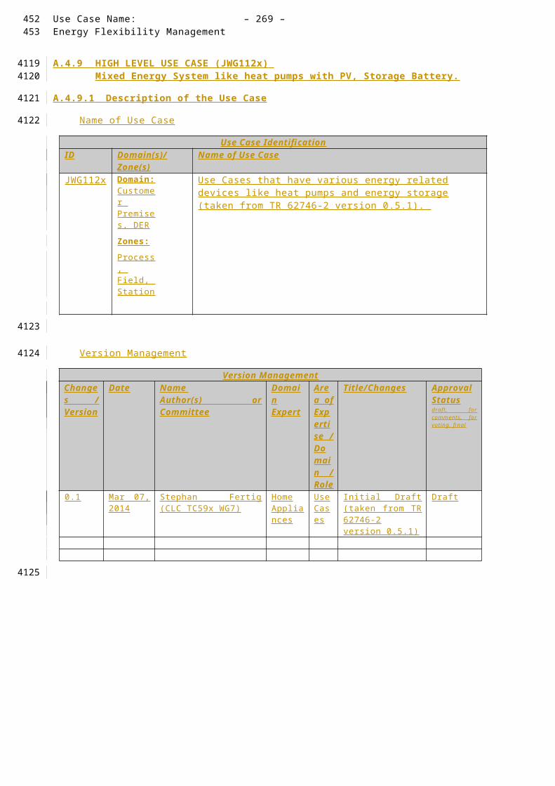
Use Case Name: – 269 –Energy Flexibility Management
388389
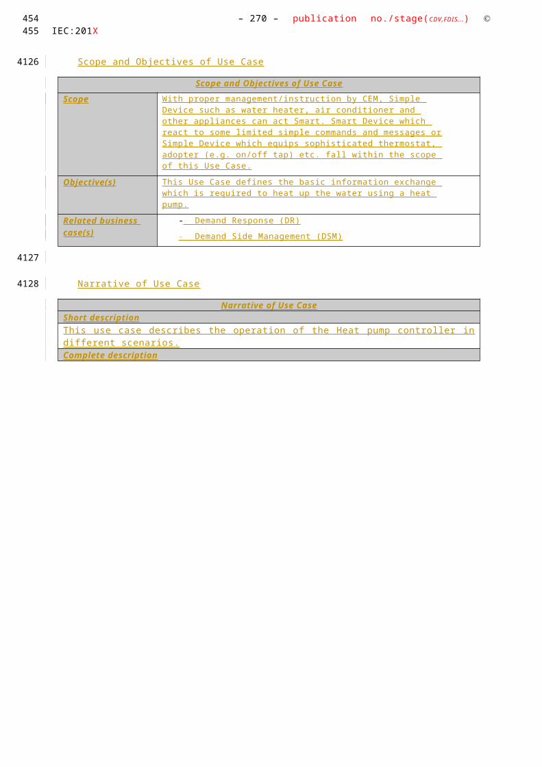
– 270 – publication no./stage(CDV,FDIS...) IEC:201X
A.4.13.3 Technical Details
Actors: People, Systems, Applications, Databases, the Power System, and Other Stakeholders
For the definition of this use case, the following architecture has been used as a basis.
Note that the actors in the above architecture are functional entities, which means that some of them may be part of the same physical device (e.g. CEM functionality may be part of a smart device, the smart meter might also encompass the smart metering gateway and CEM, etc…).
Please consider that the scope of this high level use does not require all actors shown on the figure above. Following table shows involved actors.
ActorsGrouping (Community) Group Description Actor Namesee Actor List
Actor Type see Actor List
Actor Description see Actor List
Further information specific to this Use Case
Customer Energy Manager
InternalThe CEM is a logical function optimising energy consumption and or production based on messages received from the grid, consumer’s settings and contracts, and devices minimum performance standards. The Customer Energy Manager collects messages sent to and received from connected devices; especially the in-home/building sector has to be mentioned. It can handle general or dedicated load and generation management commands and then forwards these to the connected devices. It provides vice versa information towards the “grid / market”. Note that multiple loads/generation resources can be combined in the CEM to be mutually controlled. When the CEM is integrated with communication functionalities it is called a Customer Energy Management System or CEMS
Smart ThermostatExternal
Using a Smart or programmable thermostat, one can adjust the temperature settings or the times turn on the heating or air-conditioning according to a pre-set schedule. Smart or programmable thermostats can store and repeat multiple daily settings (six or more temperature settings a day) that one can
CEM Smart Device*
Simple external consumer
display
Actor AEnergy
management gateway (EMG)
Smart Metering gateway (LNAP )
Smart meter functionalityActor B
Energy Management / Providing Flexibility (M490)
M441 architecture
Market communication
* e.g. HBES device, smart appliances, storage, generator, domestic charger for EV, complex display
Smart Grid Connection
Point
Functional metering reference architecture according the SM-CG (TR50572)
390
3844
38453846
3847
3848
3849385038513852385338543855

Use Case Name: – 271 –Energy Flexibility Management
manually override without affecting the rest of the daily or weekly program.
One can access it via the web using your tablet, smart phone or computer . The Smart Thermostat can be a device which is connected to the CEM and is programmed its settings from the CEM.
Smart deviceExternal
A smart device may be an appliance, generator or storage device (Local storage devices include direct and functional electricity storages such as electrochemical batteries, heat pumps and micro CHP such as fuel cells with heat buffers, air conditioning and cooling devices with thermal inertia, etc…) . The smart device can receive data directly from the grid, though an interface with the CEM and can react to commands and messages from the grid in an intelligent way.
Since the smart device is outside the scope of the SGCG, it must be seen as an external actor
Smart appliance (white goods)
ExternalAn example of a smart device is a smart white goods appliance which is an appliance that has the capability to act in response to a message from the grid and thereby optimize its behaviour towards the energy supply network. The message can be received from a utility or a third party energy service provider directly or via a home energy management system,
The message can be information like the cost of energy or the amount of available renewable energy, or it can be a Demand Respond message (delay load message or other related information) that the appliance must receive, interpret and react upon based on pre-set or active consumer input. The smart appliance is not guaranteed to respond, but will do so based on its status and user settings in order to ensure the expected performance.
The consumer has the ultimate control of the appliance and can override any specific mode (e.g. override a delay to allow immediate operation, limit delays to no more than a certain number of hours, or maintain a set room temperature).
Any appliance operation settings or modes shall be easy for an average, non-technical consumer to activate or implement.
Actor AExternal
External actor (Smart Grid Market Role) interacting with the system functions and components in the home or home automation network through the energy management communication channel.. Examples of such market roles are the Energy Provider, the Energy Services Provider, the aggregator, etc…
Actor BExternal
External actor (Smart Grid Market Role) interacting with the system functions and components in the home or home automation network through the metering communication channel. This actor is responsible for collecting metering data. Examples of such market roles are the DSO, metering company, etc.
UserExternal
The end customer who has acquired a smart device. The end customer is responsible for configuring and setting
391392

– 272 – publication no./stage(CDV,FDIS...) IEC:201X
operation mode of the Smart Device.
Triggering Event, Preconditions, Assumptions
Use Case ConditionsActor/System/Information/Contract
Triggering Event Pre-conditions Assumption
References
ReferencesNo. Referenc
es TypeReference Status Impact on
Use CaseOriginator / Organisation Link
1 Guideline Basic definitions and common procedures
Final Terms and definitions
SG-CG Sustainable Processes WG
ftp://ftp.cen.eu/EN/EuropeanStandardization/HotTopics/SmartGrids/Sustainable Processes.pdf
2 Technical Report
User Story and Sequence diagrams
Draft Major impact on Scenario
IEC TC57 / CLC TC205 / CLC /TC59x
-
3 Standard Use Case Template
Draft (FDIS)
Template desctription
IEC TC8 -
Further Information to the Use Case for Classification / Mapping
Classification InformationRelation to Other Use Cases Level of Depth
High Level Use Case
Prioritisation Generic, Regional or National Relation
High Level Use Case which can be applied to any kind of Smart Device. Once the regions agreed and confirmed correctness, that high level use case becomes a generic use case.
Viewpoint
This High Level Use Case has the User perspective and the interaction of the SD with an overall energy management system. It does not consider market mechanisms for flexibility offering or power grid specific implementations.
Further Keywords for Classification
Generic High Level Use Case
A.4.13.4 Step by Step Analysis of Use Case
Steps – Scenario Name
Scenario ConditionsNo. Scenario
NamePrimary Actor Triggering Event Pre-Condition Post-Condition
393
3856
3857
3858
3859
3860
3861
3862
3863
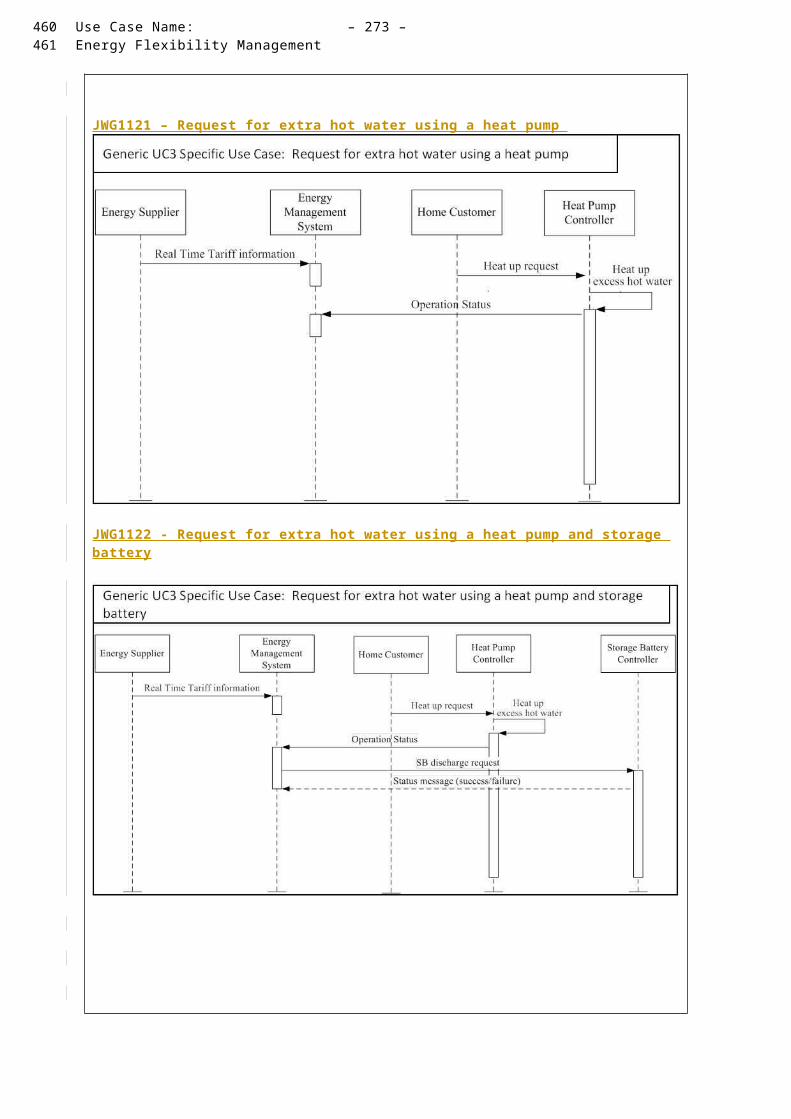
Use Case Name: – 273 –Energy Flexibility Management
Steps – Scenarios
A.4.13.5 Information ExchangedInformation Exchanged
Name of Information (ID)
Description of Information Exchanged Requirements to information data
Status Information and Events
Events that indicate system or Smart Device behaviour might be exchanged. In general, system relevant information shall be exchanged.
Such information is sensitive in a way that any modification might customer specific and confidential information. Therefore, the communication data must be protected from misuse and external influences.
Simple Commands On/Off/Start/Stop/Pause/Resume/Abort/DimTimerA ir conditioner mode:
cooling down, heating up, mode 1-nW ind: auto, high, low, etcOther settings:
Such information is sensitive in a way that any modification might turn on or off a SD
Therefore, the communication data must be protected from misuse and external influences.
Energy Profile An energy profile defines characteristics towards s specific operational mode which is applicable to the Smart Device.
Such information can be used for power consumption but also power generation.
The energy profile does not contain sensitive data in a way that it gives indication on the used Energy for a specific operational mode.
A.4.13.6 Requirements (optional)
A.4.13.7 Common Terms and DefinitionsCommon Terms and Definitions
Term Definition
A.4.13.8 Custom Information (optional)Custom Information (optional)
Key Value Refers to Section
394395
3864
3865
3866
3867
3868
3869
3870
3871
3872
3873
3874

– 274 – publication no./stage(CDV,FDIS...) IEC:201X
A.4.14 JWG2000- HLUC Demand-supply Adjustment of Cooperation between Supplier and Customer
A.4.14.1 Description of the Use Case
Name of Use Case
Use Case IdentificationID Area /
Domain(s)/ Zone(s)
Name of Use Case
JWG2000
Area : Energy SystemDomain : Customer PremisesZones : Operation, Station, Field, Process
Demand-supply Adjustment of Cooperation between Supplier and Customer
Version Management
Version ManagementVersion No.
Date Name of Author(s)
Changes Approval Status
0.1 23 /0 2 /201 4 Takashi Noguchi (IEC TC57 WG21)
Initial Creation Draft
0.2 06 / 03 /201 4 Takashi Noguchi (IEC TC57 WG21)
Minor Modifications towards style
Draft
0.3 Mar 07, 2014 Stephan Fertig (CLC TC59x)
Added Use Case ID Draft
Scope and Objectives of Use Case
Scope and Objectives of Use Case
Scope The scope of this Use Case is the communication between the CEM and upstream actors. The communication between CEM, the consumer and smart devices is officially not in this scope of this report, but will be included in the Use Case description for the sake of clarity. Smart devices cover also smart appliances, generators and storage.
When the consumer has a price dependent energy tariff and/or a time dependent distribution tariff, price based demand response is enabled by creating an incentive for load management by consumers or a CEM in response to price changes (RTP, CPP, ToU).
That is consumer suppresses energy consumption when a price is high and also increase consumption when a price is cheap on the basis of price incentive. However, if many consumers took same consumption of energy, demand will be suppressed more than necessary and increase more than expected (See Figure A). In order to avoid such problems, it is sufficient to assign a different energy price for each consumer. If prices among consumers were different, it is possible to disperse energy consumption and distribute demands (See Figure B). A supply cost is reduced if we adjust the informed price to customers for getting closer to the optimal demand curve with the minimum supply cost. Reduced supply cost can be repaid to consumers through a cut in electric rates. 1
1 Difference with other Use Cases
396
38753876
3877
3878
3879
3880
397

Use Case Name: – 275 –Energy Flexibility Management
The diagram below shows the SGCP in its environment.
Objective(s) The objective of this Use Case is to exchange information between external actors and the premise in order to:
- Enable consumers or their Energy Management System to react on (changes in) energy prices, thus supporting consumers to optimize their consumption to use cheaper energy (depending on personal preferences)
- Enable consumers to reduce the electricity tariff by receiving an appropriate price alert to avoid suppression of excessive energy use and the concentration of energy consumption 2
- Enable external actors to retrieve the state of in smart devices
Related business case(s)
This Use Case is one of the generic Use Cases of the demand response services for the buildings using in some utilities, BEMS(Building Energy Management System) aggregators, domestic projects in Japan.(This Use Case is independent from the national or regional market design. It should be agreed on the 62746-2Use Case & Requirement discussion.)
Narrative of Use Case
Narrative of Use CaseShort descriptionThis Use Case describes how information regarding price is sent from a upstream actor to CEM and how information regarding energy consumption or generation as well as smart device statuses is sent back to a upstream actor.
2 Difference with other Use Cases
398399
3881
3882
3883
400

– 276 – publication no./stage(CDV,FDIS...) IEC:201X
Complete descriptionThis Use Case is intended to achieve lower total energy cost by means of cooperation between more than one consumer and an energy supplier. Every consumer makes a profile of energy consumption with reference to initial information on prices (e.g. Hourly prices in a day) from the energy supplier. The energy supplier aggregates a profile of energy consumption from each consumer and fixes the prices again with reference to a difference between an aggregate d profile and a target profile of the energy supplier. Every consumer receives renewed price information from the energy supplier and reviews a power profile . By performing several times exchanging the information mentioned above, an aggregate d profile gets closer to a target profile of the energy supplier. Thus the energy supplier can reduce total supply cost. An electricity charge of every consumer is discounted by a reduction of the total supply cost.
ProcedureAn energy supplier determines prices after confirming a supply & demand situation and market① prices.
② A CEM receives price information from the energy supplier.③ Smart devices receive price information for planning a power profile.④ The energy supplier receives a power profile from each consumer.⑤ The energy supplier reviews the prices by reference to the received power profiles .⑥ Go back to ① .⑦ Is performed multiple times from ① to ⑥ and each consumer receive s final pric e information from
the supplier.
In addition, t his Use Case comprises two different primary Use Cases:
1. WGSP 2111: Information regarding power consumption or generation
2. WGSP 2112: Price and/or environmental information
General Remarks
General Remarks
A.4.14.2 Diagrams of Use CaseDiagram(s) of Use Case
401
3884
3885
3886
3887
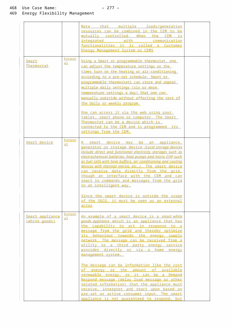
Use Case Name: – 277 –Energy Flexibility Management
A.4.14.3 T echnical Details
Actors
ActorsGrouping Group Description Actor Namesee Actor List
Actor Type see Actor List
Actor Description see Actor List
Further information specific to this Use Case
Customer Energy Manager (CEM)
Internal The CEM is a logical function optimising energy consumption and or production based on signals received from the grid, consumer’s settings and contracts, and devices minimum performance standards. The Customer Energy Manager collects messages sent to and received from connected devices; especially the in-home/building sector has to be mentioned. It can handle general or dedicated load and generation management commands and then forwards these to the connected devices. It provides vice versa information towards the “grid / market”. Note that multiple loads/generation resources can be combined in the CEM to be mutually controlled.
When the CEM is integrated with communication functionalities it is called a Customer Energy Management System or CEMS.
Smart deviceSmart appliance (white goods)
External A smart device may be an appliance, generator or storage device (Local storage devices include direct and functional electricity storages such as electrochemical batteries, heat pumps and micro CHP such as fuel cells with heat buffers, air conditioning and cooling devices with thermal inertia, etc…). The smart device can receive data directly from the grid, th r ough an interface with the CEM and can react to commands and signals from the grid in an intelligent way.
Actor A via SGCP
External External actor (Smart Grid Market Role) is interacting with the system functions and components in the home/building through the energy management communication channel. Examples of such market roles are the Energy Provider, the Energy Services Provider, the aggregator, etc…
Triggering Event, Preconditions, Assumptions
Use Case ConditionsActor/System/Information/Contract
Triggering Event
Pre-conditions Assumption
Actor AConsumer
A mutual agreement in advance(Information content, fee settlement method)
Actor ABefore price alert to a consumer from a supplier
In advance, Actor A determines prices by taking into consideration supply and demand situation, plans of energy consumption , an asking price from other suppliers and market.In order to correctly bill demand/generation flexibility, the smart meter and CEM need to be time synchronized
References
ReferencesNo. References
TypeReference Status Impact
on Use Case
Originator / Organisation
Link
Example Use Cases to WGSP2111
SG-CG Sustainable Processes WG
Example Use SG-CG
402403
3888
3889
3890
3891
3892

– 278 – publication no./stage(CDV,FDIS...) IEC:201X
Cases to WGSP2112
Sustainable Processes WG
Further Information to the Use Case for Classification / Mapping
Classification InformationRelation to Other Use CasesDistribution Management SystemLevel of DepthHigh Level Use CasePrioritisation HighGeneric, Regional or National RelationGeneric (This Use Case is independent from the national or regional market design. It should be agreed on the 62746-2Use Case & Requirement discussion.)ViewpointTechnicalFurther Keywords for ClassificationCooperation , D emand response, Smart Grid
A.4.14.4 Step by Step Analysis of Use Case
Overview of Scenarios
Scenario ConditionsNo. Scenario
NamePrimary Actor
Triggering Event
Pre-Condition Post-Condition
1 Determine initial prices
Actor A has a schedule instructing it before s end ing price information to the CEM.
Actor A stores the determined prices.
WGSP 2112
Price information
Actor A P rice information is available in Actor A .
Communication connection between all consumer s is established
Price information is received by Smart Devices
WGSP 2111
Information regarding energy consumption / generation
Smart devise
A power profile ( consumption / power output / storage for each time) is available in the CEM.
Communication connection between all actors is establishedThe smart device has a schedule instructing it when to send a power profile to the CEM.The CEM has a schedule instructing it when to send a power profile to the external actor.
A power profile is received by A ctor A
2 Aggregate power profiles and review prices
CEM Power profiles are available in Actor A.
Actor A receives a power profile from each CEM.
Actor A stores the reviewed prices.
3 Loop from No.1 to No.2 3
An aggregated profile gets close to a target profile.
WGSP 2112
Final Price information
Actor A An aggregated profile gets close to a target profile.
Communication connection between all consumer s is established
Final p rice information is received by CEM or Smart Devices
Steps – Scenarios
ScenarioScenario Name : No. 1 Price informationSt Event Name Description of Servi Informa Informat Information Req
3 Difference with other Use Cases
404
3893
3894
3895
3896
3897
3898
3899
405

Use Case Name: – 279 –Energy Flexibility Management
ep No.
of Process/ Activity
Process/ Activity ce tion Producer (Actor)
ion Receiver (Actor)
uirements , R-ID
Exchanged
1 CEM receives initial price information .
Actor A determines prices by taking into consideration supply and demand situation, plans of energy consumption , an asking price from other suppliers and market.Actor A sends price information to CEM .
Actor A CEM Price information( The price information has prices for each time in a period in order to make a plan of energy consumption. )
3 Smart Device receives initial price information .(In case of planning at CEM, it isn’t necessary to send to Smart Devices )
CEM sends price information to Smart Devices .
CEM Smart Devices
Price information
ScenarioScenario Name : No. 2 Information regarding energy consumption / generationStep No.
Event Name of Process/ Activity
Description of Process/ Activity
Service
Information Producer (Actor)
Information Receiver (Actor)
Information Requirements , R-ID
Exchanged
1 CEM or SD creates a power profile .
CEM or SD create s a power profile by using the received price information.
CEM / SD
2 CEM receives a power profile .(In case of planning a power profile at SD)
SD sends a power profile to CEM.
SD CEM Power profile( The power profile has consumption / power output / storage for each time in a period. )
3 Actor A receives power profiles.
CEM aggregates a power profile from each SD and sends a power profile of a consumer.to Actor A.
CEM Actor A Power profiles
ScenarioScenario Name : No. 3 Aggregate profiles and review pricesStep No.
Event Name of Process/ Activity
Description of Process/ Activity
Service
Information Producer (Actor)
Information Receiver (Actor)
Information Requirements , R-ID
Exchanged
1 Actor A a ggregate s power profile s and review s prices .
Actor A a ggregate s a power profile from each consumer.Actor A fixes prices again with reference to a difference between an aggregated profile and a target profile of Actor A.Actor A review s prices .
Scenario
406407
3900
3901
3902

– 280 – publication no./stage(CDV,FDIS...) IEC:201X
Scenario Name : No. 4 Loop 4 Step No.
Event Name of Process/ Activity
Description of Process/ Activity
Service
Information Producer (Actor)
Information Receiver (Actor)
Information Requirements , R-ID
Exchanged
1 Actor A and CEM exchan ge information.
Actor A and CEM exchan ge price information and a power profile several times until an aggregate d profile gets closer to a target profile of Actor A .
Price informationPower profile
ScenarioScenario Name : No. 5 Final p rice informationStep No.
Event Name of Process/ Activity
Description of Process/ Activity
Service
Information Producer (Actor)
Information Receiver (Actor)
Information Requirements , R-ID
Exchanged
1 CEM receives final price information .
Actor A sends price information to CEM .
Actor A CEM Final price information
2 Smart Device receives final price information .(In the case of planning a power profile at CEM, it isn’t necessary to send to Smart Devices )
CEM sends price information to Smart Devices .
CEM Smart Device
Final price information
A.4.14.5 Information ExchangedInformation Exchanged
Name of Information (ID)
Description of Information Exchanged
Requirements to information data
Price information (M1-1) Prices for each time in a period (e.g. Hourly prices in a day) 5
Power profile (M1-2) Consumption / power output / storage for each time in a period 6
A.4.14.6 Requirements (optional)Requirements (optional)
Categories for Requirements
Category Description
Requirement ID Requirement Description
4 Difference with other Use Cases
5 Difference with other Use Cases
6 Difference with other Use Cases
408
3903
3904
3905
3906
3907
3908
409
410
411

Use Case Name: – 281 –Energy Flexibility Management
A.4.14.7 Common Terms and DefinitionsCommon Terms and Definitions
Term Definition
A.4.14.8 Custom Information (optional)Custom Information (optional)
Key Value Refers to Section
412413
3909
3910
3911
3912

– 282 – publication no./stage(CDV,FDIS...) IEC:201X
A.4.15 HIGH LEVEL USE CASE (JWG 2001 ) “ Building Energy Management ( Model 2 ) ”
A.4.15.1 Description of the Use Case
Name of Use Case
Use Case IdentificationID Area /
Domain(s)/ Zone(s)
Name of Use Case
JWG2001 Smart Grid/Customer
“ Building Energy Management ( Model 2 ) ”Energy saving, Demand-supply control for individual buildings
Version Management
Version ManagementVersion No.
Date Name of Author(s)
Changes Approval Status
0.1 Feb. 24, 2014
Takashi Noguchi (IEC TC57 WG21)
Initial Draft Draft
0.2 Mar. 07, 2014
Stephan Fertig (CLC TC59x WG7)
Added Use Case ID Draft
Scope and Objectives of Use Case
Scope and Objectives of Use Case
Scope The scope of this use case is the communication between Actor A and CEM. The CEM has the priority information as the triage information defined by the user who manages the f acilit ies.
In this case, SGCP is located between the Actor A and the CEM.
Objective(s) The objective of this use case is the Energy saving, Demand-supply control for individual buildings.
For the demand reduction requested by the Supplier, the Service Provider (Actor A) saves energy, and adjusts the energy usage plan based on these, below.
- uses of individual Smart Devices - physical positions of individual Smart Devices - degrees of importance allocated to individual distribution line - priorities allocated to individual equipment - “consumption/generation schedules “ and
“trends of consumption/consumption result”
Related business case(s)
This Use Case is one of the generic Use Cases of the demand response services for the buildings using in some utilities, BEMS(Building Energy Management System) aggregators, domestic projects in Japan.(This Use Case is independent from the national or regional market design. It should be agreed on the 62746-2Use Case & Requirement discussion.)
Narrative of Use Case
Narrative of Use CaseShort descriptionIn advance, the building EMS (CEM) sends the estimated amount of curtailment, the priorities of Smart Devices and the area information of the building to the Actor A. So, the Actor A can perform the optimum suppression control.The Actor A calculates the consumption and generation of the electricity in individual buildings. Then
414
39133914
3915
3916
3917
3918
3919
3920
3921

Use Case Name: – 283 –Energy Flexibility Management
Actor A executes energy suppression control to perform load reduction effectively. The Actor A adjusts the energy usage plan based on above energy suppression control.
Complete description The Actor A received information of the degrees of importance, priorities and consumption/generation schedules from CEM.T he Actor A calculates the consumption and generation of the electricity in individual buildings. When s uppression power control is needed, the Actor A executes energy suppression control to perform load reduction effectively. The Actor A adjusts the energy usage plan based on above energy suppression control.
(1) The user puts degrees of importance, priorities and consumption/generation schedules into
terminal of the CEM.
(2) The CEM registers these to Actor A.
(3) The Actor A creates power profile based on uses of individual Smart Devices, physical positions of individual Smart Devices, consumption/generation schedules and trends of consumption/consumption result. Each power profile includes an operation plan of Smart Devices and incentive.And the Actor A displays power profile with incentive information to the CEM.
In case of the emergency, the Actor A creates power profile for the triage control based on “degrees of importance” and “priorities” on the above process. (4) The user selects the power profile based on the operation plan of Smart Devices and the incentive.
(5) The Actor A sends the request of reduce consumption to the CEM based on the power profile .
(6) Then the CEM adjusts the power profile based on suppression the request of reduce consumption.
General Remarks
General Remarks
A.4.15.2 Diagrams of Use CaseDiagram(s) of Use Case
Actor A(Energy supplier, SPEM)
CEM(Building EMS)
User(Facility Manager)
Estimated power profile
Power profile (with incentive information)
Smart device(Equipment)
When reduce consumption is needed
Createsadjustment plans
Emergency power profiles for the triage control (based on “degrees of importance” and “priorities”with incentive information ) Emergency power profiles for the triage
control (based on “degrees of importance” and “priorities” )
Selected emergency power profile
Request of reduce consumption Adjusts the usage plan based on the selected emergency power profile
Control
SGCP
Priority information
Estimated power profilePriority information
Selected emergency power profile
Energy suppression performance reportEnergy suppression performance report
415416
3922
3923
3924
3925
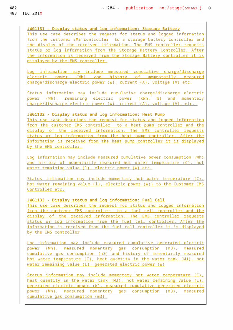
– 284 – publication no./stage(CDV,FDIS...) IEC:201X
A.4.15.3 Technical Details
Actors
ActorsGrouping Group Description Actor Namesee Actor List
Actor Type see Actor List
Actor Description see Actor List
Further information specific to this Use Case
Actor A External A company that delivers electricity to end use customers. the Energy Provider, the Energy Services Provider, the aggregator, etc…
Customer Energy Manager (CEM)
Internal The CEM is a logical function optimising energy consumption and or production based on signals received from the grid, consumer’s settings and contracts, and devices minimum performance standards. The Customer Energy Manager collects messages sent to and received from connected devices; especially the in-home/building sector has to be mentioned. It can handle general or dedicated load and generation management commands and then forwards these to the connected devices. It provides vice versa information towards the “grid / market”. Note that multiple loads/generation resources can be combined in the CEM to be mutually controlled.
User Internal Role Person
Person responsible for the maintenance and operation of the facility. In the Residential market, this is the home owner, landlord, or building superintendent.(Facility Manager)
Smart device External A smart device may be an appliance, generator or storage device (Local storage devices include direct and functional electricity storages such as electrochemical batteries, heat pumps and micro CHP such as fuel cells with heat buffers, air conditioning and cooling devices with thermal inertia, etc…). The smart device can receive data directly from the grid, though an interface with the CEM and can react to commands and signals from the grid in an intelligent way.Since the smart device is outside the scope of the SGCG, it must be seen as an external actor
Triggering Event, Preconditions, Assumptions
Use Case ConditionsActor/System/Information/Contract
Triggering Event
Pre-conditions
Assumption
Actor A Request reduce consumption
When reduce consumption is needed
References
417
3926
3927
3928
3929
3930
3931
3932

Use Case Name: – 285 –Energy Flexibility Management
ReferencesNo. References
TypeReference Status Impact on Use
CaseOriginator / Organisation
Link
1 Example use cases to the reduce control in Model 2
WGSP212 0: Direct load / generation management
Further Information to the Use Case for Classification / Mapping
Classification InformationRelation to Other Use CasesJapanese Use Case Model 3Level of DepthHigh Level Use CasePrioritisation HighGeneric, Regional or National RelationGeneric (This Use Case is independent from the national or regional market design. It should be agreed on the 62746-2Use Case & Requirement discussion.)ViewpointTechnicalFurther Keywords for ClassificationDemand side management, direct load control, Smart Grid , Building Energy Management
A.4.15.4 Step by Step Analysis of Use Case
Overview of Scenarios
Scenario ConditionsNo. Scenario
NamePrimary Actor Triggering Event Pre-Condition Post-Condition
1 “Building Energy Management ( Model 2 ”)Energy saving, Demand-supply control for individual buildings
Actor A Request of reduce consumption
Communication connection between all actors is established
The user configured the CEM and/or the participating Smart Devices. The user set the priorities of Smart Devices to the CEM.
Information on total consumption or consumption per device is notified to the CEM
The power profile is negotiated between Actoer A and CEM.
The Smart D evice s are controlled by the CEM based on the negotiated power profile.
Steps – Scenarios
ScenarioScenario Name :
“Building Energy Management ( Model 2 ”)Energy saving, Demand-supply control for individual buildings
Step No.
Event Name of Process/ Activi
Description of Process/ Activity
Service Information Producer (Actor)
Information Receiver (Actor)
Information Require-ments , R-ID
Exchanged
418419
3933
3934
3935
3936
3937
3938
3939
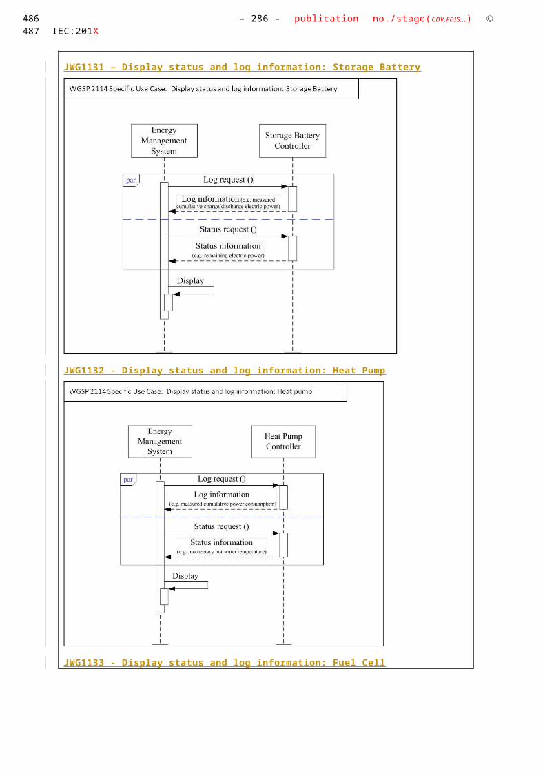
– 286 – publication no./stage(CDV,FDIS...) IEC:201X
ty1 Set
degrees of importance, priorities to the CEM
The User sets the degrees of importance, priorities to the CEM.
Field/ Building
User CEM degrees of importance, priorities for individual Smart Devices
2 Set estimated power profile to the CEM
The User sets the estimated power profile to the CEM.
Field/ Building
User CEM estimated power profile
3 Set degrees of importance, priorities to the Actor A
The CEM sets the degrees of importance, priorities to the Actor A.
Field/ Building
CEM Actor A degrees of importance, priorities for individual Smart Devices
4 Set estimated power profile to the Actor A
The CEM sets the estimated power profile to the Actor A.
Field/ Building
CEM Actor A estimated power profile
5 Create power profile
Actor A creates power profile in consideration of degrees of importance, priorities and estimated power profile.
Field -- -- --
6 Send power profile to the CEM
Actor A sends power profile with a incentive information..
Field/ Building
Actor A CEM power profile with a incentive information
7 Detect the need for reduce consumption
Actor A detects the need for reduce consumption.
Field -- -- --
8 Notify the emergency power profiles
Actor A sends the Emergency power profiles for the triage control based on “degrees of importance” and “priorities” to the CEM.
Field/ Building
Actor A CEM Emergency power profiles for the triage control based on “degrees of importance” and “priorities”
9 Notify the emergency power profiles
CEM sends the emergency power profiles for the triage control based on “degrees of importance” and “priorities” to User.
Building CEM User Emergency power profiles for the triage control based on “degrees of importance” and “priorities”
10 Selects the emergen
User sends the selected emergency
Building User CEM Selected emergency power profile
420

Use Case Name: – 287 –Energy Flexibility Management
cy power profiles
power profile to the CEM.
11 Selects the emergency power profiles
CEM sends the selected emergency power profile to the Actor A.
Field/ Building
CEM Actor A Selected emergency power profile
12 Request of reduce consumption
Actor A sends the request of reduce consumption to the CEM.
Field/ Building
Actor A CEM Request of reduce consumption
13 Load control
CEM controls to the equipment
Building CEM Smart Devices
Smart Device control signal
14 Report Smart Devices reports suppression performance
Building Smart Devices
CEM Energy suppression performance report
15 Report CEM reports suppression performance
Field/ Building
CEM Actor A Energy suppression performance report
A.4.15.5 Information ExchangedInformation Exchanged
Name of Information (ID)
Description of Information Exchanged Requirements to information data
Priority information(M2-1)
Priority information ( degrees of importance, priorities ) of the each smart devices ( load s) in the customer building for triage control.
Estimated Power Profile (M2-2)
Individual Smart Device consumption/Generation information estimated by the user.
Power Profile (M2-3) Power profile includes incentive and re-created plans of consumption schedules, generation schedules of the customer’s building.
Request of reduce consumption (M2-4)
Emergency Notification includes the request information to reduce the power consumption in the customer building.
Emergency Power Profile for the triage control (M2-5)
Adjusted Power Profile for the triage control includes the re-calculated power consumption/control plan based on the triage control with incentive information
Selected Power Profile (M2-6)
Response to the Emergency Power Profile for the triage control, including the power profile selected by user.
Request of reduce consumption (M2-7)
Request of reduce consumption is the suppression signal which is the request information to start suppression control of Smart Devices in the building based on the Selected Power Profile.
C ontrol (M2-8) This signal is the control signal for the Smart Devices in the building.
Energy suppression performance report (M2-9)
Report of energy suppression performance.
421422
3940
3941
3942

– 288 – publication no./stage(CDV,FDIS...) IEC:201X
A.4.15.6 Requirements (optional)Requirements (optional)
Categories for Requirements
Category Description
Requirement ID Requirement Description
A.4.15.7 Common Terms and DefinitionsCommon Terms and Definitions
Term Definition
A.4.15.8 Custom Information (optional)Custom Information (optional)
Key Value Refers to Section
A.4.16 HIGH LEVEL USE CASE (JWG 2 0 02 ) “ Energy Management of Groups of Building in the District ( Model 3 ) ”
A.4.16.1 Description of the Use Case
Name of Use Case
Use Case IdentificationID Area /
Domain(s)/ Zone(s)
Name of Use Case
JWG2002
Smart Grid/Customer
“ Energy Management of Groups of Building in the District ( Model 3 ) ”Energy saving, Demand-supply control for group of buildings
Version Management
Version ManagementVersion No.
Date Name of Author(s)
Changes Approval Status
0.1 Feb. 21, 2014
Takashi Noguchi (IEC TC57 WG21)
Initial Draft Draft
0.2 Mar. 07, 2014
Stephan Fertig (CLC TC59x WG7)
Added Use Case ID Draft
Scope and Objectives of Use Case
Scope and Objectives of Use Case
Scope The scope of this Use Case is the communication between the District Service Provider EMS (D-SPEM) and the Groups of Building EMS (G-CEM). The Groups of Building EMS (G-CEM) has the group information (e.g. town block) in the district with gather energy information of each buildings defined by the f acility manager.
423
3943
3944
3945
3946
3947
39483949
3950
3951
3952
3953
3954
3955

Use Case Name: – 289 –Energy Flexibility Management
In this case, SGCP is located between the District Service Provider EMS (D-SPEM) and the Groups of Building EMS (G-CEM).
EMS: Energy Management SystemObjective(s) The objective of this Use Case is the Energy saving, Demand-supply control
for groups of buildings. For the demand reduction request by the Energy Supplier, the District
Service Provider EMS (D-SPEM) saves energy, and adjusts “demands of the district” based on these, below. -uses of individual equipment
-District Service Provider EMS (D-SPEM) creates “proposal for adjustment plans” based on the priority, the power usage plan and the consumption of buildings and equipment.
-“consumption/generation schedules “and “trends of consumption/consumption result”
-calculates the demand curtailment ability of the district.
Energy usage optimization - such as demand suppression, energy saving, emission reduction, renewable energy usage promotion - can be achieved by energy management of group of buildings (town block). So user benefits are obtained as follows: -Scalability: The amount of adjustable energy consumption can be
Increases because of a total amount of energy consumption increases. -Diversity: Mutually complementary energy operation is attained by many
Kinds of distributed energy resources and loads. It is easy to take energy balance.
Related business case(s)
This Use Case is one of the generic Use Cases of the demand response services for the buildings using in some utilities, BEMS(Building Energy Management System) aggregators, domestic projects in Japan.(This Use Case is independent from the national or regional market design. It should be agreed on the 62746-2Use Case & Requirement discussion.)
Narrative of Use Case
Narrative of Use CaseShort descriptionThe energy supplier calculates the consumption and generation of the electricity in a district with
gathering each building energy information. Then energy supplier executes energy suppression control to perform load reduction effectively. The district service provider EMS (D-SPEM) adjusts the energy usage plan based on above energy suppression control.
Complete descriptionThe district service provider (D-SEPM) receives priority and power usage plan of the building, then
creates power usage plan and equipment operation plan for group of the building. The energy supplier calculates the consumption and generation of the electricity in a district. Then energy supplier executes energy suppression control to perform load reduction effectively. The district service provider (D-
District Service Provider EMS (D-SPEM)
Groups of Building EMS (G-CEM)
Building EMS
BuildingBuilding
BuildingBuildingBuilding
District ServiceProvider EMS
Energy Supplier
Group of Buildings
EMS
SGCP
Group of Buildings
EMS
Building
Groups of Buildings Energy Management
Town Block(Group)
424425
3956
3957

– 290 – publication no./stage(CDV,FDIS...) IEC:201X
SPEM) adjusts the energy usage plan based on above energy suppression control. (1)The facility manager inputs the priority and the power usage plan of the building into the Building EMS.
G-CEM aggregates these information and add building information (e.g. apartment house, commercial building, public facilities, factory, ..).Then, the G-CEM registers these to the D-SPEM and Energy Supplier.
(2)The D-SPEM creates the “power usage plan” and the “equipment operation plan” for the Town Block (a group of buildings based on a contract). G-CEM decomposes these information for each building and then registers these to his Building EMS.
(3)When a suppression control of power is needed, the supplier calculates the demand curtailment ability of the district. Then the Supplier creates a new power usage plan of the district. Next, the supplier sends it to the D-SPEM. After the D-SPEM receives it, he creates “proposal for adjustment plans” based on the priority, the power usage plan and the consumption of buildings and equipment. Each of these proposals includes an “equipment operation plan” and an incentive. Then the D-SPEM sends these proposals to G-CEM. Then G-CEM decomposes them for each building and sends them to Building EMS.
(4)The Facility manager checks these proposals at the Building EMS terminal in the Customer’s building. Then the Facility manager selects one of these proposals based on the “equipment operation plan” and incentive. The Building EMS sends the selected proposal to G-CEM. G-CEM aggregates these proposals and sends to D-SPEM.
(5)After the D-SPEM receives the proposal selected by the Customer, the D-SPEM sends signals according to the proposal.
(6)The Building EMS adjusts the power usage plan based on signals received, and control equipments.
(7)The Equipment reports energy suppression performance to Building EMS, G-CEM, D-SPEM and Energy Supplier.
General Remarks
General Remarks
A.4.16.2 Diagrams of Use CaseDiagram(s) of Use Case
426
3958
3959
3960
3961

Use Case Name: – 291 –Energy Flexibility Management
A.4.16.3 Technical Details
Actors
ActorsGrouping Group Description Actor NameSee Actor List
Actor Type see Actor List
Actor Description see Actor List
Further information specific to this Use Case
Actor A External External actor (Smart Grid Market Role) interacting with the system functions and components in the home/building or home/building automation network through the energy management communication channel.. Examples of such market roles are the Energy Provider, the Energy Services Provider, the aggregator, etc…
In addition in this Use Case Actor A consists of Energy Supplier and District Service Provider EMS (D-SPEM).Energy Supplier is a company that
delivers electricity to end use customers.D-SPEM manages energy saving
and demand-supply for the Groups of Buildings (e.g. town block) in the district.
CEM Internal The CEM is a logical function optimising energy consumption and or production based on signals received from the grid, consumer’s settings and contracts, and devices minimum performance standards. The Customer Energy Manager collects messages sent to and received from connected devices; especially the in-home/building sector has to be mentioned. It can handle general or dedicated load and generation management commands and then forwards these to the connected
427428
3962
3963
3964

– 292 – publication no./stage(CDV,FDIS...) IEC:201X
devices. It provides vice versa information towards the “grid / market”. Note that multiple loads/generation resources can be combined in the CEM to be mutually controlled.
When the CEM is integrated with communication functionalities it is called a Customer Energy Management System or CEMS.
In addition in this Use Case CEM consists of Group of Buildings EMS (G-CEM) and Building EMS.
G-CEM manages energy saving and demand-supply for the Group of Buildings.
Building EMS is a system used to monitor and control the energy consuming devices in a building.
User InternalRole Person Facility manager responsible for the
maintenance and operation of the facility. In the Residential market, this is the home owner, landlord, or building superintendent.
Smart Device External A smart device may be an load , generator or storage device/equipment (Local storage devices include direct and functional electricity storages such as electrochemical batteries, heat pumps and micro CHP such as fuel cells with heat buffers, air conditioning and cooling devices with thermal inertia, etc…) . The smart device can receive data directly from the grid, though an interface with the CEM and can react to commands and signals from the grid in an intelligent way.
Since the smart device is outside the scope of the SGCG, it must be seen as an external actor
Triggering Event, Preconditions, Assumptions
Use Case ConditionsActor/System/Information/Contract
Triggering Event
Pre-conditions
Assumption
Actor A (Energy Supplier)Request of Suppression power control
References
ReferencesNo. References
TypeReference Status Impact on Use
CaseOriginator / Organisation
Link
429
3965
3966
3967
3968
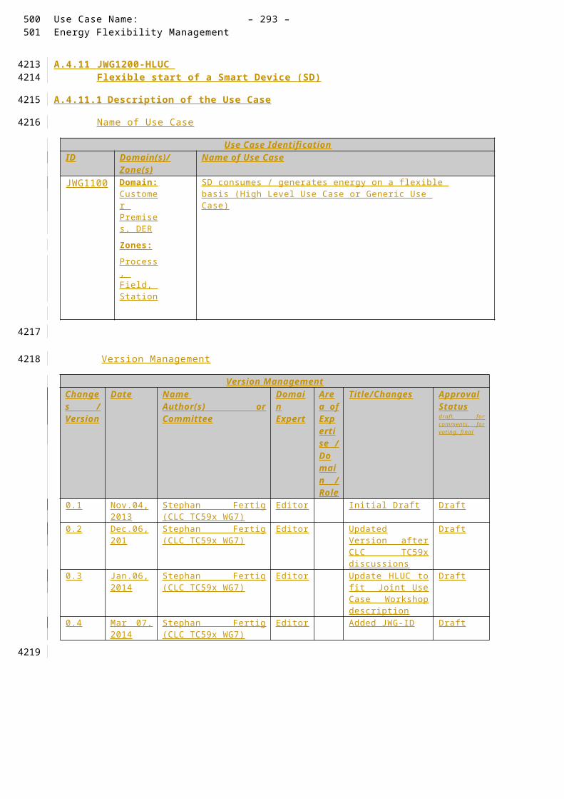
Use Case Name: – 293 –Energy Flexibility Management
Further Information to the Use Case for Classification / Mapping
Classification InformationRelation to Other Use CasesJapanese Use Case Model 2, Model 4Level of DepthHigh Level Use CasePrioritisation HighGeneric, Regional or National RelationGeneric (This Use Case is independent from the national or regional market design. It should be agreed on the 62746-2Use Case & Requirement discussion.)ViewpointTechnicalFurther Keywords for ClassificationDemand side management, Smart Grid, Building Energy Management. District
A.4.16.4 Step by Step Analysis of Use Case
Overview of Scenarios
Scenario ConditionsNo. Scenario
NamePrimary Actor Triggering Event Pre-Condition Post-Condition
“Group of Building s in the District ( Model 3 ) ”Energy saving, Demand- supply adjustment for the district
Actor A ( Energy Supplier )
Request of Suppression power control
Steps – Scenarios
ScenarioScenario Name :
Energy saving, Demand-supply adjustment for the district
Step No.
Event Name of Process/ Activity
Description of Process/ Activity
Service
Information Producer (Actor)
Information Receiver (Actor)
Information Require-ments , R-ID Exchange
d
1 Facility manager inputs the priority and the power usage plan of the building into the Building EMS.
G-CEM aggregates these information and add building information (e.g. apartment house, commercial building , public facilit y, factory , ..).Then, the G-CEM
registers these to the
User(Facility Manager)
CEM(Building EMS, Group of Buildings EMS (G-CEM))
CEM(Building EMS)
Actor A(District Service Provider EMS (D-SPEM), Energy Supplier)
Aggregated Priority information (M3-1)
Aggregated Power usage plan of the building (M3-2)
Aggregated Building information(M3-3)
430431
3969
3970
3971
3972
3973
3974
3975

– 294 – publication no./stage(CDV,FDIS...) IEC:201X
D-SPEM and Energy Supplier.
2 The D-SPEM creates the “power usage plan” and the “equipment operation plan” for the Town Block (a group of buildings based on a contract).
G-CEM decompose these information for each building and then registers these to his Building EMS .
Actor A(District Service Provider EMS (D-SPEM))
CEM(Group of Buildings EMS (G-CEM),Building EMS (CEM))
Power usage plan for the Group of Buildings (M3-4)
3 When a suppression control of power is needed,
T he energy supplier calculates the demand curtailment ability of the district. Then the energy s upplier creates a new power usage plan of the district. Next, the energy supplier sends it to the D-SPEM Provider.
After the D-SPEM receives it, he creates “proposal for adjustment plans” .. Then the D-SPEM sends these proposals to G-CEM.
Then G-CEM decompose s them for each building and send s them to Building EMS and Facility manager .
Actor A(Energy Supplier,District Service Provider EMS (D-SPEM))
CEM(Group of Buildings EMS (G-CEM),Building EMS)
User(Facility manager)
Proposals for adjustment plan (M3-7)
4 The Facility manager checks these proposals at the Building EMS terminal in the Customer’s building. Then the Facility manager selects one of these proposals based on the “equipment operation
plan” and incentive. The Building EMS
sends the selected proposal to G-CEM. G-CEM aggregates
these proposals and sends to D-SPEM.
User(Facility manager),
CEM(Building EMS,Group of Buildings EMS (G-CEM))
Actor A(District Service Provider EMS (D-SPEM))
Aggregated Selected proposal (M3-8)
5 After the D-SPEM receives the proposal selected by the Customer, the D-SPEM sends suppression signals for groups of building according to the proposal.
Actor A(District Service Provider EMS (D-SPEM))
CEM(Group of Buildings EMS (G-CEM),Building EMS)
Suppression signal for group of building (M3-9)
6 The Building EMS adjusts the power usage plan based on suppression signals received.
CEM(Building EMS)
Smart Device(Equipment)
Equipment operation schedule (M3-10)
432

Use Case Name: – 295 –Energy Flexibility Management
Then Building EMS sends Equipment operation schedule and/or control to the equipment
7 The Equipment reports the energy suppression performance
Smart Device(Equipment)
CEM, (Building EMS,Group of Buildings EMS (G-CEM)
Actor A(District Service Provider EMS (D-SPEM), Energy Supplier).
Aggregated report (M3-11)
A.4.16.5 Information ExchangedInformation Exchanged
Name of Information (ID)
Description of Information Exchanged Requirements to information data
Aggregated Priority information (M3-1)
Aggregated Priority information for the group of building.Priority information is a power supply priority level for each equipment in a building (e.g. lighting, office equipment, air conditioner, .. ). Priority level may be categorized such as Critical, Curtailable, and so on.
Aggregated Power usage plan of the building (M3-2)
Time series of power consumption plan in the future (e.g. day ahead, week ahead, .. ) for the group of building by aggregating each building declaration.
Aggregated B uilding information (M3-3)
Aggregated Building information for the group of building. B uilding information includes building category and characteristic such as apartment house, store, public facilities, and so on.
Power usage plan for the Group of Buildings (M3-4)
Time series of power consumption plan in the future (e.g. day ahead, week ahead, .. ) for the group of building given by Actor A (District service provider EMS (D-SPEM)). Power usage plan includes equipment operation schedule (e.g. on/off, set-point, .. ) correspondence with each power consumption plan.
Demand curtailment ability of the District (M3-5)
Power consumption curtailment margin for the district.
[Not Applicable, Information within Actor A at Step No.3]
Power usage plan of the district (M3-6)
Time series of power consumption plan in the future (e.g. day ahead, a week ahead, .. ) for the district.
[Not Applicable, Information within Actor A at Step No.3]
Proposals for adjustment plan (M3-7)
Proposals for adjustment plan are created based on priority, power usage plan and consumption of buildings and equipments. These proposals include equipment operation plan and incentive.
Aggregated Selected proposal (M3-8)
Aggregated selected proposal for group of building.Selected proposal is facility manager’s selection of proposals for each building offered by CEM.
Suppression signals for Groups of Building (M3-9)
Power consumption requirement to the group of building given by Actor A (District service provider EMS (D-SPEM)).
Equipment operation schedule (M3-10)
Equipment operation schedule for each equipment in a building according with Actor A’s Suppression signals for group of building.
Aggregated report (M3- Aggregated energy suppression performance
433434
3976
3977

– 296 – publication no./stage(CDV,FDIS...) IEC:201X
11) report of group of building.
A.4.16.6 Requirements (optional)Requirements (optional)
Categories for Requirements
Category Description
Requirement ID Requirement Description
A.4.16.7 Common Terms and DefinitionsCommon Terms and Definitions
Term Definition
A.4.16.8 Custom Information (optional)Custom Information (optional)
Key Value Refers to Section
435
3978
3979
3980
3981
3982
3983
3984

Use Case Name: – 297 –Energy Flexibility Management
A.4.17 HIGH LEVEL USE CASE (JWG 2010 ) Acceleration of producing power by REs
A.4.17.1 Description of the Use Case
Name of Use Case
Use Case IdentificationID Area /
Domain(s)/ Zone(s)
Name of Use Case
JWG2010 DER, Customer Premises
Acceleration of producing power by REs
Version Management
Version ManagementVersion No.
Date Name of Author(s)
Changes Approval Status
0.1 Feb. 18, 2014
Takashi Noguchi (IEC TC57 WG21)
Initial Draft Draft
0.2 Mar. 07, 2014
Stephan Fertig (CLC TC59x WG7)
Added Use Case ID Draft
Scope and Objectives of Use Case
Scope and Objectives of Use Case
Scope The scope of this Use Case is the communication among the D istrict S ervice P rovider E nergy M anagement S ystem(D-SPEM), the” C ommunity E nergy S upplier owning Renewable sources(CES) / C ommunity E nergy saving service P rovider (CEP)” Energy Management System (C-EMS) and the Building Energy Management System.
In this case, SGCP is located among the D-SPEM, the C-EMS and the Building Energy Management System.
EMS: Energy Management SystemObjective(s) The objective of this Use Case is the acceleration of producing power by
Renewable sources of Energy. This is achieved by registration of information
D-SPEM
C-EMS
Building-EMSBuilding
District ServiceProvider EMS
Energy Supplier
SGCP
CES/CEPEMS
Building
436437
39853986
3987
3988
3989
3990
3991
3992

– 298 – publication no./stage(CDV,FDIS...) IEC:201X
regarding the bulding and the Community Energy Supplier owning Renewabe sources of Energy (CES) / Community Energy saving service Provider (CEP).
Related business case(s)
This Use Case is one of the generic Use Cases of the demand response services for the buildings using in some utilities, BEMS (Building Energy Management System) aggregators, domestic projects in Japan.(This Use Case is independent from the national or regional market design. It should be agreed on the 62746-2Use Case & Requirement discussion.)
Narrative of Use Case
Narrative of Use CaseShort descriptionT he District Service Provider EMS (D-SPEM) calculates the ratio of energy contribution to the district
by Customers owning Renewable sources of Power ( R E s ) . Then the District Service Provider EMS (D-SPEM) gives Customers owning REs an incentive based on their individual energy contribution to the district.Complete description(1)The CEM (Building EMS, C-EMS) registers “the building id and e stimated energy profile with respect to each power classification 7 of Smart Devices ” to the Actor A(Energy supplier&D-SPEM).(2) The Actor A (Energy supplier&D-SPEM) estimates the power produced by REs and the consumption of Customers.(3) The Actor A (Energy supplier&D-SPEM) create s the plan for the distribution to Customers .(4) The Actor A (Energy supplier&D-SPEM) sends the plan for the distribution.(5) The CEM (Building EMS, C-EMS) receives confirmation from his terminal, and sends control signals to the SmartDevice.(6) The Smart Device sends results to the CEM(Building EMS, C-EMS).(7) The CEM (Building EMS, C-EMS] sends amount of the power produced by REs to the Actor A (Energy supplier&D-SPEM).(8) The Actor A (Energy supplier&D-SPEM) calculate incentive.(9) The Actor A (Energy supplier&D-SPEM) sends incentive information to the CEM (Building EMS, C-EMS).(10) The CEM (Building EMS, C-EMS) receives confirmation from his terminal.
General Remarks
General Remarks
A.4.17.2 Diagrams of Use CaseDiagram(s) of Use Case
7 i.e. RE, non-RE, Load
438
3993
3994
3995
3996
3997
3998
439

Use Case Name: – 299 –Energy Flexibility Management
A.4.17.3 Technical Details
Actors
ActorsGrouping Group Description Actor Namesee Actor List
Actor Type see Actor List
Actor Description see Actor List
Further information specific to this Use Case
Actor A External External actor (Smart Grid Market Role) interacting with the system functions and components in the home /building or home /building automation network through the energy management communication channel.. Examples of such market roles are the Energy Provider, the Energy Services Provider, the aggregator, etc…
In addition in this Use Case, Actor A consists of Energy Supplier and District Service Provider EMS ( D-SPEM) .Energy Supplier is a company that delivers electricity to end use customers.D-SPEM manages energy saving
and demand-supply for Self-sastaining District/Disaster Recovery.
CEM Internal The CEM is a logical function optimising energy consumption and or production based on signals received from the grid, consumer’s settings and contracts, and devices minimum performance standards. The Customer Energy Manager collects messages sent to and received from connected devices; especially the in-
Actor A(Energy supplier&D-SPEM)
CEM(Building EMS)
Smart Device(REs, non-REs, Load)
-control signals
-estimate the power produced using REs and the consumption of Customers-create the plan for the distribution to Customers
-plan for the distribution -confirmation
-results
-amount of the power produced using REs
-confirmation
SGCP
-incentive infromation
-building id, power classification-estimated power profile
-calculate incentive
Building
-In case of CES/CEP, CEM consists of C-EMS-And Smart Device consists of REs, non-REs)
CES/CEP
CES : Community Energy Supplier owning REs (e.g. Biomass Business), CEP : Community Energy saving service ProviderD-SPEM: District Service Provider EMS, C-EMS: CES/CEP EMSPower classif ication : i.e. RE, non-RE, Load, RE : Renewable source of Energy (e.g. Solar Photovoltaic)
440441
3999
4000
4001

– 300 – publication no./stage(CDV,FDIS...) IEC:201X
home/building sector has to be mentioned. It can handle general or dedicated load and generation management commands and then forwards these to the connected devices. It provides vice versa information towards the “grid / market”. Note that multiple loads/generation resources can be combined in the CEM to be mutually controlled.
When the CEM is integrated with communication functionalities it is called a Customer Energy Management System or CEMS .
In addition in this Use Case, CEM consists of CES/CEP EMS(C-CEM) and Building EMS.C-CEM manages “adjustment of
energy production & consumption in normal conditions” and “Energy accommodation in disaster conditions.”Building EMS is a system used to
monitor and control Smart Dvices
Smart Device External A smart device may be an appliance, generator or storage device (Local storage devices include direct and functional electricity storages such as electrochemical batteries, heat pumps and micro CHP such as fuel cells with heat buffers, air conditioning and cooling devices with thermal inertia, etc…). The smart device can receive data directly from the grid, though an interface with the CEM and can react to commands and signals from the grid in an intelligent way.Since the smart device is outside the scope of the SGCG, it must be seen as an external actor
In addition in this Use Case, Smart Device consists of “REs, non-REs and load.”
442

Use Case Name: – 301 –Energy Flexibility Management
Triggering Event, Preconditions, Assumptions
Use Case ConditionsActor/System/Information/Contract
Triggering Event
Pre-conditions
Assumption
CEM
Registration of information regarding the bulding and the Community Energy Supplier owning REs/Community Energy saving service Provider (CES/CEP)
References
ReferencesNo. References
TypeReference Status Impact on Use
CaseOriginator / Organisation
Link
Further Information to the Use Case for Classification / Mapping
Classification InformationRelation to Other Use CasesJapanese Use Case Model2, Model3Level of DepthHigh Level Use CasePrioritisation HighGeneric, Regional or National RelationGeneric (This Use Case is independent from the national or regional market design. It should be agreed on the 62746-2Use Case & Requirement discussion.)ViewpointTechnicalFurther Keywords for ClassificationSmart Grid, Self-sustaining District, Disaster Recovery
A.4.17.4 Step by Step Analysis of Use Case
Overview of Scenarios
Scenario ConditionsNo. Scenario
NamePrimary Actor Triggering Event Pre-Condition Post-Condition
1 Acceleration of producing power by REs
CEM registration of information regarding the bulding.
443444
4002
4003
4004
4005
4006
4007
4008
4009
4010

– 302 – publication no./stage(CDV,FDIS...) IEC:201X
Steps – Scenarios
ScenarioScenario Name :
No. 1 Acceleration of producing power by REs
Step No.
Event Name of Process/ Activity
Description of Process/ Activity
Service Information Producer (Actor)
Information Receiver (Actor)
Information Require-ments , R-ID Exchange
d1 The CEM
(Building EMS, C-EMS) registers “the building id and e stimated energy profile with respect to each power classification 8 of Smart Devices ” to the Actor A(Energy supplier&D-SPEM).
CEM(Building EMS, C-EMS)
Actor A(Energy supplier&D-SPEM)
building id
e stimated energy profile with respect to each power classification 9 of Smart Devices
2 The Actor A (Energy supplier&D-SPEM) estimates the power produced by REs and the consumption of Customers.
Actor A(Energy supplier&D-SPEM)
3 The Actor A (Energy supplier&D-SPEM) create s the plan for the distribution to Customers .
The Actor A(Energy supplier&D-SPEM)
4 The Actor A (Energy supplier&D-SPEM) sends the plan for the distribution.
The Actor A (Energy supplier&D-SPEM)
CEM (Building EMS, C-EMS)
plan for the distribution
5 The CEM (Building EMS, C-EMS) receives confirmation from his
CEM (Building EMS, C-EMS)
SmartDevice control signals
8 i.e. RE, non-RE, Load
9 i.e. RE, non-RE, Load
445
4011
4012
446
447

Use Case Name: – 303 –Energy Flexibility Management
terminal, and sends control signals to the SmartDevice.
6 The Smart Device sends results to the CEM(Building EMS, C-EMS).
SmartDevice
CEM (Building EMS, C-EMS)
results
7 The CEM (Building EMS, C-EMS] sends amount of the power produced by REs to the Actor A (Energy supplier&D-SPEM).
CEM (Building EMS, C-EMS)
Actor A (Energy supplier&D-SPEM)
amount of the power produced by REs
8 The Actor A (Energy supplier&D-SPEM) calculate incentive.
- -
9 The Actor A (Energy supplier&D-SPEM) sends incentive information to the CEM (Building EMS, C-EMS)
Actor A (Energy supplier&D-SPEM)
CEM (Building EMS, C-EMS)
Incentive information
10 The CEM (Building EMS, C-EMS) receives confirmation from his terminal
- -
A.4.17.5 Information ExchangedInformation Exchanged
Name of Information (ID)
Description of Information Exchanged Requirements to information data
building id (M4-1-1) The building id is information to identify indivisual building.
e stimated energy profile with respect to each power classification 10 of Smart Devices (M4-
The estimated energy profile consists of energy profile with respect to each power classification of Smart Devices.
10 i.e. RE, non-RE, Load
448449
4013
4014
450

– 304 – publication no./stage(CDV,FDIS...) IEC:201X
1-2)plan for the distribution (M4-1-3)
The plan is planning information to distribute electrical power to Customers.
control signals (M4-1-4)
The control signals consists signals for control Smart Devices.
results (M4-1-5) The results includes results of controlling Smart Device.
amount of the power produced by REs (M4-1-6)
The amount of power is created by CEM as results of controlling Smart Device that produce power by REs.
Incentive information (M4-1-7)
The information is calculated by Actor A(Energy supplier&D-SPEM)
A.4.17.6 Requirements (optional)Requirements (optional)
Categories for Requirements
Category Description
Requirement ID Requirement Description
A.4.17.7 Common Terms and DefinitionsCommon Terms and Definitions
Term Definition
A.4.17.8 Custom Information (optional)Custom Information (optional)
Key Value Refers to Section
451
4015
4016
4017
4018
4019
4020
4021
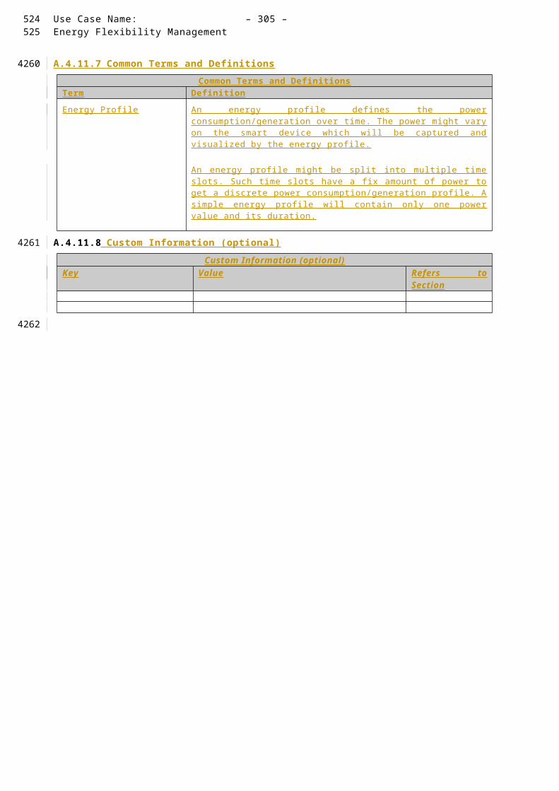
Use Case Name: – 305 –Energy Flexibility Management
A.4.18 High Level Use Case Adjustment of energy production & consumption in normal conditions
A.4.18.1 Description of the Use Case
Name of Use Case
Use Case IdentificationID Area /
Domain(s)/ Zone(s)
Name of Use Case
JWG2011 DER, Customer Premises
Adjustment of energy production & consumption in normal conditions
Version Management
Version ManagementVersion No.
Date Name of Author(s)
Changes Approval Status
0.1 Feb. 18, 2014
Takashi Noguchi (IEC TC57 WG21)
Initial Draft Draft
0.2 Mar. 07, 2014
Stephan Fertig (CLC TC59x WG7)
Added Use Case ID Draft
Scope and Objectives of Use Case
Scope and Objectives of Use Case
Scope The scope of this Use Case is the communication among the D istrict S ervice P rovider E nergy M anagement S ystem(D-SPEM), the” C ommunity E nergy S upplier owning Renewable sources(CES) / C ommunity E nergy saving service P rovider (CEP)” Energy Management System (C-EMS) and the Building Energy Management System.
In this case, SGCP is located among the D-SPEM, the C-EMS and the Building Energy Management System.
EMS: Energy Management SystemObjective(s) The objective of this Use Case is the acceleration of producing power by
Renewable sources of Energy. This is achieved by registration of information
Building-EMS
C-EMS
D-SPEM
Building
District ServiceProvider EMS
Energy Supplier
SGCP
CES/CEPEMS
Building
452453
40224023
4024
4025
4026
4027
4028
4029

– 306 – publication no./stage(CDV,FDIS...) IEC:201X
regarding the bulding and the Community Energy Supplier owning Renewabe sources of Energy (CES) / Community Energy saving service Provider (CEP).
Related business case(s)
This Use Case is one of the generic Use Cases of the demand response services for the buildings using in some utilities, BEMS (Building Energy Management System) aggregators, domestic projects in Japan.(This Use Case is independent from the national or regional market design. It should be agreed on the 62746-2Use Case & Requirement discussion.)
Narrative of Use Case
Narrative of Use CaseShort descriptionThe District Service Provider EMS (D-SPEM) manages the production of electricity using Renewable
sources of Energy (REs) owned by Customers. Then, the District Service Provider EMS (D-SPEM) sends a signal to the CEM in order to accelerate the production or decelerate the production.Then, the CES/CEP EMS (C-CEM) updates the production plan.Complete description(1) The Actor A (D-SPEM) estimates the future production of electricity using the weather information. Then, the Actor A (D-SPEM) decides that the production of electricity will be insufficient for the demand or exceed the demand in the near future.(2) T he Actor A (D-SPEM) sends the signal for accelerating the production(production plan) or decelerating the production(production plan) to the CEM (C-CEM).(3) T he CEM (C-CEM) updates the production plan. Then, The CEM (C-CEM) sends the control request (Smart device ID-power profile) to the CEM (Building CEM).(4) The CEM (Building CEM) receives confirmation from its terminal. Then, The CEM (Building CEM) sends the reply to the CEM (C-CEM).(5) The CEM (C-CEM) updates the production plan. Then,the CEM (C- CEM) sends the control signal (Smart device ID-power profile) to the CEM (Building CEM).(6) The CEM (Building CEM) sends the control signal (power profile) to the Smart Device.(7) The Smart Device sends the results to the CEM (Building EMS).(8) The CEM sends the results to the CEM (C- CEM).(9) The CEM (C- CEM) sends the control signal(pwer profile) to the Smart Device.(10) The Smart Device sends the results to the CEM (C- CEM).(11) The CEM (C- CEM) sends the results to the Actor A (D-SPEM).
General Remarks
General Remarks
A.4.18.2 Diagrams of Use CaseDiagram(s) of Use Case
454
4030
4031
4032
4033
4034
4035

Use Case Name: – 307 –Energy Flexibility Management
A.4.18.3 Technical Details
Actors
ActorsGrouping Group Description Actor Namesee Actor List
Actor Type see Actor List
Actor Description see Actor List
Further information specific to this Use Case
Actor A External External actor (Smart Grid Market Role) interacting with the system functions and components in the home /building or home /building automation network through the energy management communication channel.. Examples of such market roles are the Energy Provider, the Energy Services Provider, the aggregator, etc…
In addition in this Use Case, Actor A consists of District Service Provider EMS ( D- SPEM) .The D-SPEM manages energy
saving and demand-supply for Self-sastaining District/Disaster Recovery.
CEM Internal The CEM is a logical function optimising energy consumption and or production based on signals received from the grid, consumer’s settings and contracts, and devices minimum performance standards. The Customer Energy Manager collects messages sent to and received from connected devices; especially the in-home/building sector has to be mentioned. It can handle general or dedicated load and generation management commands and then forwards these to the connected devices. It provides vice versa information towards the “grid / market”. Note that multiple loads/generation resources can be
-results
CEM(C-CEM)
CEM(Building EMS)
-decides that the production of electricity will be insufficient for the demand or exceed the demand in the near future
-updates the production plan
-confirmation
-control request (Smart device ID-power profile)
-reply
SGCP
Smart Device(Res, non-REs)
-results
-control signal(Smart device ID-power profile)
-result
CES/CEP
Actor A(D-SPEM)
-signal for accelerating the production(production plan) or decelerating the production(production plan)
-updates the production plan
-control signal(power profile)
-results
Smart Device(REs, non-Res, Load)
-estimates future production of electricity using the weather information
-control signal(power profile)
Building
CES : Community Energy Supplier owning REs (e.g. Biomass Business), CEP : Community Energy saving service ProviderD-SPEM: District Service Provider EMS, C-EMS: CES/CEP EMSPower classif ication : i.e. RE, non-RE, Load, RE : Renewable source of Energy (e.g. Solar Photovoltaic)
455456
4036
4037
4038

– 308 – publication no./stage(CDV,FDIS...) IEC:201X
combined in the CEM to be mutually controlled.
When the CEM is integrated with communication functionalities it is called a Customer Energy Management System or CEMS .
In addition in this Use Case, CEM consists of CES/CEP EMS(C-CEM) and Building EMS.C-CEM manages “adjustment of
energy production & consumption in normal conditions” and “Energy accommodation in disaster conditions.”Building EMS is a system used to
monitor and control Smart Dvices
Smart Device External A smart device may be an appliance, generator or storage device (Local storage devices include direct and functional electricity storages such as electrochemical batteries, heat pumps and micro CHP such as fuel cells with heat buffers, air conditioning and cooling devices with thermal inertia, etc…). The smart device can receive data directly from the grid, though an interface with the CEM and can react to commands and signals from the grid in an intelligent way.Since the smart device is outside the scope of the SGCG, it must be seen as an external actor.
In addition in this Use Case, Smart Device consists of “REs, non-REs and load.”
457

Use Case Name: – 309 –Energy Flexibility Management
Triggering Event, Preconditions, Assumptions
Use Case ConditionsActor/System/Information/Contract
Triggering Event
Pre-conditions
Assumption
Actor A
decides that the production of electricity will be insufficient for the demand or exceed the demand in the near future
References
ReferencesNo. References
TypeReference Status Impact on Use
CaseOriginator / Organisation
Link
Further Information to the Use Case for Classification / Mapping
Classification InformationRelation to Other Use CasesJapanese Use Case Model2, Model3Level of DepthHigh Level Use CasePrioritisation HighGeneric, Regional or National RelationGeneric (This Use Case is independent from the national or regional market design. It should be agreed on the 62746-2Use Case & Requirement discussion.)ViewpointTechnicalFurther Keywords for ClassificationSmart Grid, Self-sustaining District, Disaster Recovery
A.4.18.4 Step by Step Analysis of Use Case
Overview of Scenarios
Scenario ConditionsNo. Scenario
NamePrimary Actor Triggering Event Pre-Condition Post-Condition
1 Adjustment of energy production & consumption in normal conditions
Actor A decides that the production of electricity will be insufficient for the demand or exceed the demand in the near future
458459
4039
4040
4041
4042
4043
4044
4045
4046
4047

– 310 – publication no./stage(CDV,FDIS...) IEC:201X
Steps – Scenarios
ScenarioScenario Name :
No. 1 Adjustment of energy production & consumption in normal conditions
Step No.
Event Name of Process/ Activity
Description of Process/ Activity
Service Information Producer (Actor)
Information Receiver (Actor)
Information Require-ments , R-ID Exchange
d1 The Actor
A (D-SPEM) estimates the future production of electricity using the weather information. Then, the Actor A (D-SPEM) decides that the production of electricity will be insufficient for the demand or exceed the demand in the near future.
Actor A - -
2 The Actor A(D-SPEM) sends the signal for accelerating the production(production plan) or decelerating the production(production plan) to the CEM (C-CEM).
Actor A (D-SPEM)
CEM (C-CEM)
signal for accelerating the production(production plan) or decelerating the production(production plan)
3 The CEM (C-CEM) updates the production plan. Then, The CEM (C-CEM) sends the control request (Smart device ID-power profile) to the CEM
CEM (C-CEM)
CEM (Building CEM)
control request (Smart device ID-power profile)
460
4048
4049

Use Case Name: – 311 –Energy Flexibility Management
(Building CEM).
4 The CEM (Building CEM) receives confirmation from its terminal. Then, The CEM (Building CEM) sends the reply to the CEM (C-CEM).
CEM (Building CEM)
CEM (C-CEM)
reply
5 The CEM (C-CEM) updates the production plan. Then,the CEM (C- CEM) sends the control signal (Smart device ID-power profile) to the CEM (Building CEM).
CEM (C-CEM)
CEM (Building CEM)
control signal (Smart device ID-power profile)
6 The CEM (Building CEM) sends the control signal (power profile) to the Smart Device.
CEM (Building CEM)
Smart Device
control signal(power profile)
7 The Smart Device sends the results to the CEM (Building EMS).
Smart Device
CEM (Building EMS)
results
8 The CEM sends the results to the CEM (C- CEM).
CEM (Building EMS)
CEM (C- CEM)
results
9 The CEM (C- CEM) sends the control signal(pwer profile) to the Smart Device.
CEM (C- CEM)
Smart Device
control signal
10 The Smart Device sends the results to
Smart Device
CEM (C- CEM)
results
461462

– 312 – publication no./stage(CDV,FDIS...) IEC:201X
the CEM (C- CEM).
11 The CEM (C- CEM) sends the results to the Actor A (D-SPEM).
CEM (C- CEM)
Actor A (D-SPEM)
resutls
A.4.18.5 Information ExchangedInformation Exchanged
Name of Information (ID)
Description of Information Exchanged Requirements to information data
signal for accelerating the production (M4-2-1)
The signal includes production accelerating signal and production plan.
signal for decelerating the production (M4-2-2)
The signal includes production decelerating signal and production plan.
control request (M4-2-3)
The signal includes the request for control, the Smart Device id and the power profile.
reply (M4-2-4) The reply is the answer for the control request.
control signa l(M4-2-5)
The signal consist of “the Smart Device id and the power profile” or only power profile.
results (M4-2-6) The results are created by the Smart Deivce as a result of controlling the CEM (Building EMS) or CEM (C-CEM).
A.4.18.6 Requirements (optional)Requirements (optional)
Categories for Requirements
Category Description
Requirement ID Requirement Description
A.4.18.7 Common Terms and DefinitionsCommon Terms and Definitions
Term Definition
A.4.18.8 Custom Information (optional)Custom Information (optional)
Key Value Refers to Section
463
4050
4051
4052
4053
4054
4055
4056
4057
4058

Use Case Name: – 313 –Energy Flexibility Management
A.4.19 HIGH LEVEL USE CASE (JWG 2012 ) Energy accommodation in disaster conditions
A.4.19.1 Description of the Use Case
Name of Use Case
Use Case IdentificationID Area /
Domain(s)/ Zone(s)
Name of Use Case
JWG2012 DER, Distribution, Customer Premises
Energy accommodation in disaster conditions
Version Management
Version ManagementVersion No.
Date Name of Author(s)
Changes Approval Status
0.1 Feb. 18, 2014
Takashi Noguchi (IEC TC57 WG21)
Initial Draft Draft
0.2 Mar. 07, 2014
Stephan Fertig (CLC TC59x WG7)
Added Use Case ID Draft
Scope and Objectives of Use Case
Scope and Objectives of Use Case
Scope The scope of this Use Case is the communication among the D istrict S ervice P rovider E nergy M anagement S ystem(D-SPEM), the” C ommunity E nergy S upplier owning Renewable sources(CES) / C ommunity E nergy saving service P rovider (CEP)” Energy Management System (C-EMS) and the Building Energy Management System.
In this case, SGCP is located among the D-SPEM, the C-EMS and the Building Energy Management System.
EMS: Energy Management SystemObjective(s) The objective of this Use Case is the acceleration of producing power by
Building-EMS
C-EMS
D-SPEM
Building
District ServiceProvider EMS
Energy Supplier
SGCP
CES/CEPEMS
Building
464465
40594060
4061
4062
4063
4064
4065
4066

– 314 – publication no./stage(CDV,FDIS...) IEC:201X
Renewable sources of Energy. This is achieved by registration of information regarding the bulding and the Community Energy Supplier owning Renewabe sources of Energy (CES) / Community Energy saving service Provider (CEP).
Related business case(s)
This Use Case is one of the generic Use Cases of the demand response services for the buildings using in some utilities, BEMS (Building Energy Management System) aggregators, domestic projects in Japan.(This Use Case is independent from the national or regional market design. It should be agreed on the 62746-2Use Case & Requirement discussion.)
Narrative of Use Case
Narrative of Use CaseShort descriptionIn case of a disaster, the Community Energy Supplier owning Renewable sources of Energy ( CES ) /
Community Energy saving service Provider ( CEP) changes the “power supply plan for normal situations” to the “power supply plan for disaster situations,” in order to keep providing power to “disaster control centers.” On the “power supply plan for disaster situations,” the CES/CEP supplies the electrical and the thermal power to the “Disaster Control Center”.Complete description(1) The CEM (Building EMS) sends the power profile for disaster situation to the CEM (C-CEM).(2) The CEM (C-CEM) sends the aggregated power profile for disaster situation to the Actor A (Energy supplier&D-SPEM).(3) The Actor A (Energy supplier&D-SPEM) adjust the the aggregated power profiles for disaster situation. Then, the Actor A (Energy supplier&D-SPEM) sends the aggregated power profile for disaster situation to the CEM (C-CEM).(4) The CEM (C-CEM) sends the power profile for disaster situation to the CEM (Building EMS).(5) The CEM (C-CEM) and the CEM (Building EMS) send the status report to the Actor A (Energy supplier&D-SPEM).(6) The Actor A (Energy supplier&D-SPEM) sends disaster signal to the CEM (C-CEM).(7) The CEM (C-CEM) changes the plan (to power profile for disaster situation). Then, the CEM (C-CEM) sends discharge signal to the Smart Device.(8) The CEM (C-CEM) sends -accommodation report to the CEM (Building EMS).(9) The Smart Device sends the results to the CEM (Building EMS).(10) The CEM (Building EMS) sends the results to the CEM (C-CEM).
General Remarks
General Remarks
A.4.19.2 Diagrams of Use CaseDiagram(s) of Use Case
Smart Device(REs, non-Res, Load)
CEM(C-CEM)
Building
Smart Device(Res, non-REs)
-status report
-discharge signal
-power profile for disaster situations
-adjustment of the aggregated power profiles for disaster situation
-aggregated power profile for disaster situation-power profile for disaster situation
-status report
-disaster signal
-accommodation report
SGCP
CES/CEP
Actor A(Energy supplier&D-SPEM)
- changes the plan (to power profile for disaster situation)
CEM(Building EMS)
-results -results
-aggregated power profile for disaster situations
466
4067
4068
4069
4070
4071
4072

Use Case Name: – 315 –Energy Flexibility Management
A.4.19.3 Technical Details
Actors
ActorsGrouping Group Description Actor Namesee Actor List
Actor Type see Actor List
Actor Description see Actor List
Further information specific to this Use Case
Actor A External External actor (Smart Grid Market Role) interacting with the system functions and components in the home /building or home /building automation network through the energy management communication channel.. Examples of such market roles are the Energy Provider, the Energy Services Provider, the aggregator, etc…
In addition in this Use Case, Actor A consists of District Service Provider EMS ( D- SPEM) .The D-SPEM manages energy
saving and demand-supply for Self-sastaining District/Disaster Recovery.
CEM Internal The CEM is a logical function optimising energy consumption and or production based on signals received from the grid, consumer’s settings and contracts, and devices minimum performance standards. The Customer Energy Manager collects messages sent to and received from connected devices; especially the in-home/building sector has to be mentioned. It can handle general or dedicated load and generation management commands and then forwards these to the connected devices. It provides vice versa information towards the “grid / market”. Note that multiple loads/generation resources can be combined in the CEM to be mutually controlled.
When the CEM is integrated with communication functionalities it is called a Customer Energy Management System or CEMS .
In addition in this Use Case, CEM consists of CES/CEP EMS(C-CEM) and Building EMS.C-CEM manages “adjustment of
energy production & consumption in normal conditions” and “Energy accommodation in disaster conditions.”Building EMS is a system used to
monitor and control Smart Dvices
Smart Device External A smart device may be an appliance, generator or storage device (Local storage devices include direct and functional electricity storages such as electrochemical batteries, heat pumps
CES : Community Energy Supplier owning REs (e.g. Biomass Business), CEP : Community Energy saving service ProviderD-SPEM: District Service Provider EMS, C-EMS: CES/CEP EMSPower classif ication : i.e. RE, non-RE, Load, RE : Renewable source of Energy (e.g. Solar Photovoltaic)
467468
4073
4074
4075

– 316 – publication no./stage(CDV,FDIS...) IEC:201X
and micro CHP such as fuel cells with heat buffers, air conditioning and cooling devices with thermal inertia, etc…). The smart device can receive data directly from the grid, though an interface with the CEM and can react to commands and signals from the grid in an intelligent way.Since the smart device is outside the scope of the SGCG, it must be seen as an external actor.
In addition in this Use Case, Smart Device consists of “REs, non-REs and load.”
469

Use Case Name: – 317 –Energy Flexibility Management
Triggering Event, Preconditions, Assumptions
Use Case ConditionsActor/System/Information/Contract
Triggering Event
Pre-conditions
Assumption
CEM (Building EMS)
sends the power profile for disaster situation to the CEM (C-CEM)
References
ReferencesNo. References
TypeReference Status Impact on Use
CaseOriginator / Organisation
Link
Further Information to the Use Case for Classification / Mapping
Classification InformationRelation to Other Use CasesJapanese Use Case Model2, Model3Level of DepthHigh Level Use CasePrioritisation HighGeneric, Regional or National RelationGeneric (This Use Case is independent from the national or regional market design. It should be agreed on the 62746-2Use Case & Requirement Meeting)ViewpointTechnicalFurther Keywords for ClassificationSmart Grid, Self-sustaining District, Disaster Recovery
Classification InformationRelation to Other Use CasesJapanese Use Case Model2, Model3Level of DepthHigh Level Use CasePrioritisation HighGeneric, Regional or National RelationGeneric (This Use Case is independent from the national or regional market design. Of cause, it should be agreed on the 62746-2Use Case & Requirement discusstion.)ViewpointTechnicalFurther Keywords for ClassificationSmart Grid, Self-sustaining District, Disaster Recovery
A.4.19.4 Step by Step Analysis of Use Case
Overview of Scenarios
Scenario ConditionsNo. Scenario
NamePrimary Actor Triggering Event Pre-Condition Post-Condition
1 Energy CEM (Building sends the power
470471
4076
4077
4078
4079
4080
4081
4082
4083
4084

– 318 – publication no./stage(CDV,FDIS...) IEC:201X
accommodation in disaster conditions
EMS) profile for disaster situation to the CEM (C-CEM)
Steps – Scenarios
ScenarioScenario Name :
No. 1 Energy accommodation in disaster conditions
Step No.
Event Name of Process/ Activity
Description of Process/ Activity
Service Information Producer (Actor)
Information Receiver (Actor)
Information Require-ments , R-ID Exchange
d1 The CEM
(Building EMS) sends the power profile for disaster situation to the CEM (C-CEM).
CEM (Building EMS)
CEM (C-CEM) power profile for disaster situation
2 The CEM (C-CEM) sends the aggregated power profile for disaster situation to the Actor A (Energy supplier&D-SPEM).
CEM (C-CEM)
Actor A (Energy supplier&D-SPEM)
aggregated power profile for disaster situation
3 The Actor A (Energy supplier&D-SPEM) adjust the the aggregated power profiles for disaster situation. Then, the Actor A (Energy supplier&D-SPEM) sends the aggregated power profile for disaster situation to the CEM (C-CEM).
Actor A (Energy supplier&D-SPEM)
CEM (C-CEM) aggregated power profile for disaster situation
4 The CEM (C-CEM) sends the power profile for disaster situation to the CEM (Building EMS).
CEM (C-CEM)
CEM (Building EMS)
power profile for disaster situation
5 The CEM (C-CEM) and the CEM (Building EMS) send the status report to the Actor A (Energy
CEM (C-CEM)
CEM (Building EMS)
status report
472
4085
4086
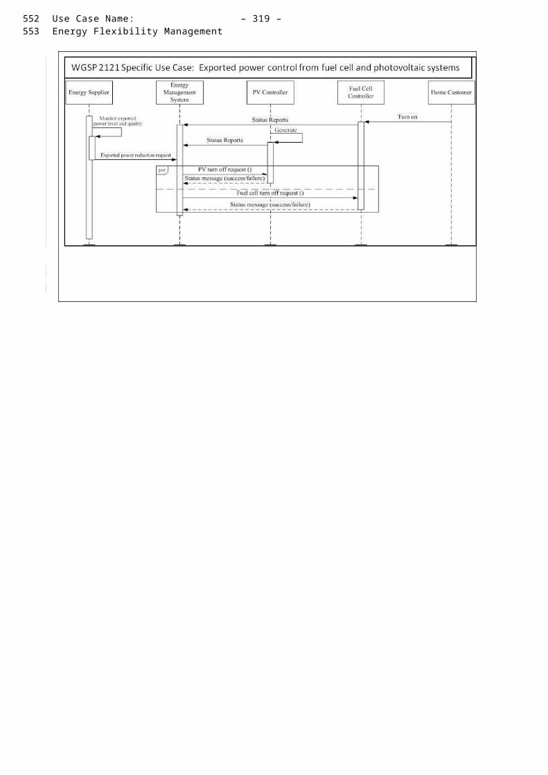
Use Case Name: – 319 –Energy Flexibility Management
supplier&D-SPEM)
6 The Actor A (Energy supplier&D-SPEM) sends disaster signal to the CEM (C-CEM).
Actor A (Energy supplier&D-SPEM)
CEM (C-CEM) disaster signal
7 The CEM (C-CEM) changes the plan (to power profile for disaster situation). Then, the CEM (C-CEM) sends discharge signal to the Smart Device.
CEM (C-CEM)
Smart Device discharge signal
8 The CEM (C-CEM) sends -accommodation report to the CEM (Building EMS).
CEM (C-CEM)
CEM (Building EMS)
accommodation report
9 The Smart Device sends the results to the CEM (Building EMS).
Smart Device
CEM (Building EMS)
results
10 The CEM (Building EMS) sends the results to the CEM (C-CEM).
CEM (Building EMS)
CEM (C-CEM) results
A.4.19.5 Information ExchangedInformation Exchanged
Name of Information (ID)
Description of Information Exchanged Requirements to information data
power profile for disaster situations (M4-3-1)
The profile consists of the power profiles of each disastersituation.
aggregated power profile for disaster situation (M4-3-2)
First, the profile is created by aggregating the power profile for disaster situations ofbuildings.Second, the profile is adjusted by the Actor A (Energy supplier&D-SPEM) .
status report (M4-3-3) The report is the status of the CEM (C-CEM) or the CEM (Building EMS).
disaster signal (M4-3-4)
The signal is created by the Actor A (Energy supplier&D-SPEM).
discharge signal (M4-3-5)
The signal is created by the CEM (C-CEM) for the accommodation of power to the Building.
results (M4-3-6) The results is created by Smart Devices for repoting of accommodation.
473474
4087
4088

– 320 – publication no./stage(CDV,FDIS...) IEC:201X
A.4.19.6 Requirements (optional)Requirements (optional)
Categories for Requirements
Category Description
Requirement ID Requirement Description
A.4.19.7 Common Terms and DefinitionsCommon Terms and Definitions
Term Definition
A.4.19.8 Custom Information (optional)Custom Information (optional)
Key Value Refers to Section
475
4089
4090
4091
4092
4093
4094
4095

Use Case Name: – 321 –Energy Flexibility Management
A.4.20 JWG30xx - SP UC Energy Flexibility Management
A.4.20.1 Description of the Use Case s
Name of Use Case
ID Domainsee Annex A Selection List
Name of Use Case Level of DepthCluster, High Level Use Case, Detailed Use Case
JWG30xx Smart Building in Smart Grid
Energy Flexibility Management High level Use Cases
Version Management
Changes / Version
Date Name Author(s) or Committee
Domain Expert Area of Expertise / Domain / Role
Title Approval Statusdraft, for comments, for voting, f inal
0.9 29.11.12 Rolf Apel (IEC TC8)
Smart Grid draft
1.0 08.01.13 Rolf Apel (IEC TC8)
Smart Grid 1 st review
1.1 21.01.13 Rolf Apel (IEC TC8)
Smart Grid Final draft version (content)
2.0 25.02.14 Rolf Apel (IEC TC8)
Smart Grid Allignment for IEC TC57 JWG use case
2.1 March 07, 2014
Stephan Fertig (TC57 JWG)
Home Appliances Use Cases
Integration into JWG activity:
‘- Use Case IDs‘- Basic information section
Draft
Basic Information to Use Case
ReferencesNo. Referenc
es TypeReference Status Impact on
Use CaseOriginator / Organisation Link
1 Guideline Basic definitions and common procedures
Final Terms and definitions
SG-CG Sustainable Processes WG (SGTF EG1)
http://ec.europa.eu/energy/gas_electricity/smartgrids/doc/xpert_group1_sustainable_processes.pdf
2 Technical Report
User Story and Sequence diagrams
Draft Major impact on Scenario
IEC TC57 / CLC TC205 / CLC /TC59x
-
3 Standard Use Case Template
Draft (FDIS)
Template desctription
IEC TC8 -
4 Guideline Smart Grid Reference Architecture
Final Terms and definitions
SG-CG Architecture Working Group (SGTF EG1)
http://ec.europa.eu/energy/gas_electricity/smartgrids/doc/xpert_group1_reference_architecture.pdf
Relation to Higher Level Use Case
476477
40964097
4098
4099
4100
4101
4102
4103
41044105
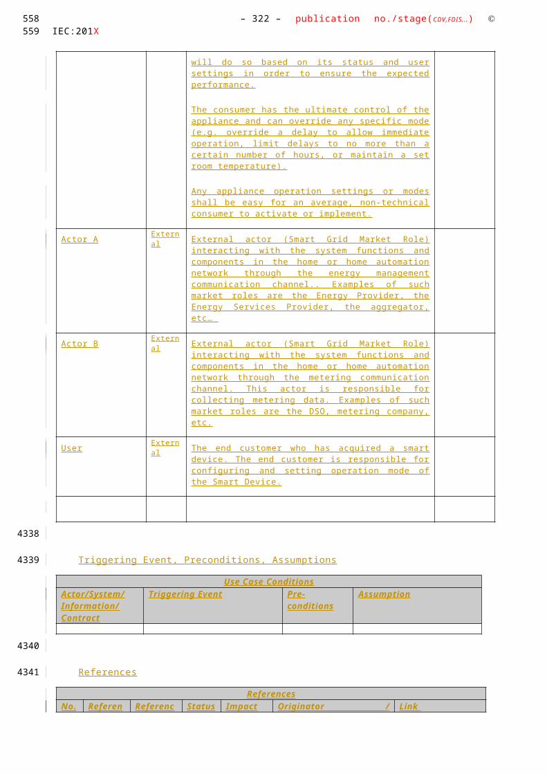
– 322 – publication no./stage(CDV,FDIS...) IEC:201X
Cluster Higher Level Use Case
Maturity of Use Case – in business operation, realized in demonstration project, , realised in R&D, in preparation, visionary
Prioritisation Generic, Regional or National Relation View - Technical / Business
Further Keywords for Classification
Scope and Objectives of Use Case
Scope and Objectives of Function
The purpose of this document is to define the Use Cases for the automated operation of demand side management in the area of Smart Buildings in Smart Grids
Narrative of Use Case
Narrative of Use CaseShort description – max 3 sentences
A demand response event may be initiated by a power system operator in response to a reliability event, e.g., loss of a generating station causing a lack of supply to meet demand, or an uncontrolled set of PEVs overloading of a distribution transformer. A demand response event may also be initiated by system based on economic considerations, e.g., reducing or shifting peak load at the system level or at specific feeder or facility. Demand response may also be initiated by a customer in response to a market pricing signal or information about the “green index” of the supplied energy. The green index specifies the share of renewable energy in the actual energy mix.
Complete descriptionDemand Response is deployed for economic or a reliability purposes. At high penetration levels, demand response has to be integrated with the power supply scheduling process, and it may impact the distribution grid operation and reliability, and perhaps the transmission grid operation and reliability. Thus it is important to include the required considerations for the grid and system level operations when developing DR Use Cases and DR signal standards. Such impacts may not be significant at low penetration levels; however, proper considerations must be given to support scalability and expandability for future deployments. Power system operates based on a real-time balancing of supply and demand. To economically schedule the supply, an accurate load forecast is needed. Traditionally, load forecast was generated using the historical consumption patterns, weather forecast and other similar parameters. With the potential of high-penetration of DR, it will be necessary to incorporate the planned or forecasted DR levels into the load forecast. Also, DR capabilities can be used to support the power system capacity or emergency supply (ancillary service) needs. Such services require proper scheduling and monitoring capabilities.A demand response event may be initiated by a power system operator in response to a reliability event, e.g., loss of a generating station causing a lack of supply to meet demand, or an uncontrolled set of PEVs overloading of a distribution transformer. A demand response event may also be initiated by system based on economic considerations, e.g., reducing or shifting peak load at the system level or at specific feeder or facility. Demand response may also be initiated by a customer in response to a market pricing signal.Considering that the distribution grid in a number of countries is a three-phase imbalance circuit, i.e., many customers are on a single-phase or two-phase of the three-phase system. Thus significant changes in customer load patters could result in undesirable imbalanced conditions on a feeder. Also, load pickup following the termination of a major DR event could possibly cause overloads and other operational problems, if the load pickup is not properly scattered/managed.
Dynamic Price-based DR or Real-Time Pricing (RTP)Traditionally, retail tariff has based on a fixed or tiered rate structure with possible considerations of static rates for pre-established time of use (TOU) conditions. Real time or dynamic pricing (RTP) represent retail electricity rate that could vary as a function of time and is intended to modify demand. It requires interval metering for accurate billing based on time-varying prices. A number of countries have implemented RTP or other dynamic pricing tariffs for large customers. With a broader deployment of advanced meters, RTP rates may become more common world-wide also for smaller customers.The scenario presented here includes the case where a location-dependent real-time retail pricing for energy is established based on the wholesale Locational Marginal Price (LMP) for that location. LMP values are typically established by an ISO (for regions covered by an ISO/RTO) on a day-ahead (hourly resolution) and real-time basis, typically on a five minute resolution. For the RTP, it will be appropriate to use the real-time LMP as the basis for computing the retail dynamic tariff. However, decisions should be made on the time and the spatial resolution of the RTP. For example, an hourly RTP averaging the five minute pricing values, or a Critical Peak Pricing model to reflect the extreme conditions only, may be adopted. In addition to the wholesale energy price,
478
4106
4107
4108
4109
4110

Use Case Name: – 323 –Energy Flexibility Management
the retail RTP rate may also include the appropriate uplift charges to cover for distribution wire/services charges and for the power loss compensations. Note that the uplift charges are typically subject to a regulatory review and approval.Special care must be given to the RTP rate design to ensure customer acceptance and adaptation. Also grid operational issues may have to be addressed. For example, during low LMP (RTP) periods (e.g., at night), certain distribution circuits may get over loaded (congested), with customers shifting consumption, e.g., charging PEVs, to that period. This improves the overall system economy, but may cause circuit congestion. To combat this, some have proposed use of demand charges or an additional incentive payment for load reduction, a locational incentive to relief congestion.
Notification Based DR ExecutionNotification-based DR is mostly used for economic purposes based on a day-ahead or hour-ahead basis. Notification-based DR may also be used for reliability events when the system operator expects a contingency or operating condition (e.g., congestion or planned outage) on the distribution or the transmission grid that requires a reduction (or an increase in case of too much distributed generation) on the load at a given location.Considering that the business processes for demand response have not yet been standardized across the nations, the following is a representative scenario that captures some of the interactions between the key stakeholders (actors).At high penetration levels, the DR operation, especially on a day-ahead or hour ahead basis, need to be coordinated with the overall operations and supply scheduling process. This may require a timely update of the “locational” load forecast and an up-to-date nomination of the DR capabilities. This information may be supplied to the “system” and/or market operator to be incorporated in the overall supply and demand scheduling process. The DR capabilities are specified by the DR Provider (VPP operator) to the System Operator based on a DR Program, a price curve, or other nomination protocol. The DR Provider may also inform the energy retailer of the locational available DR capabilities.The notification-based DR dispatch process is typically initiated by the System or Market Operator; the process may also be initiated by the retailer or the DSO. It is also possible that the DR Provider (VPP operator) be the initiator of the DR process based on a market opportunity (economic operation) or based on a pre-established program.At high DR penetration levels, it is expected that the DR provider will need to clear the DR schedule with the Distribution Grid Operator. This is to insure that the high penetration DR has no adverse impact on the distribution grid reliability and power quality, e.g., cause of excessive imbalances, voltage violation, or an overload during load pickup period. The DSO, in a timely fashion, will inform the DR Provider, if the schedule is cleared or requires an adjustment. Please note that if the DR deployed by a utility company that includes both, retailer and DSO functions, such coordination is performed within the company’s operational systems (e.g., DRMS, DMS, etc.), or it can be an integral part of the DR scheduling application.Following the clearing the DR schedule, notifications are sent to customers for DR operation. Under this scenario, the Market Operator and the retailer are also informed of the final DR schedule.
Direct Load Control (DLC)Direct-Load Control is typically used for reliability-based events such as contingency and emergency support, supply of balancing energy or other ancillary service. Many of these programs require quick response time, e.g., five minutes or faster, that is practically only possible through a DLC capability. Direct-Load Control may also be used for economic operations, e.g., water heater programs to reduce or shift peak load. Considering that the business processes for demand response have not yet been standardized across the nations, the following is a representative DLC scenario that captures the interactions between the key stakeholders (actors).Direct Load Control is typically called by a system operator, a transmission or distribution operator. It could be also issued by a Market Operator based on an ancillary service DR award, or by a retailer or DR operator (VPP operator) for an economic purpose. At high penetration levels, DLC operation needs to be coordinated with the distribution grid operator.The customer DR capabilities are aggregated by location and specified/nominated to the Distribution Grid Operator, retailer, and/or to the System/Market Operator. In addition to location, the capabilities may also be aggregated by the DR response time, e.g., four seconds, five minutes, 30 minutes, etc. The DLC Dispatch process is typically initiated by the Transmission or Distribution Operator. The process may also be initiated by the Market Operator of the retailer. The actual control of the DR resources may be done by the DR provider (VPP provider) based on the dispatch signal received.At high DR penetration levels, it is expected that the DLC activation schedule to be coordinated with the Distribution Grid Operator. This is to insure that there are no adverse impact on the distribution grid reliability and power quality, e.g., voltage violation, excessive phase imbalances, or an overload during load pickup period. If the DLC deployed by a utility company such coordination can be accomplished within the company’s DR and distribution management systems, or performed as an integral part of the DR control functions. For a “fast” DR, e.g., provision of ancillary services, a telemetry capability is required to enable the real-time monitoring of the resource condition and its response to the DR control signal.
Taking the above described base principles into consideration, the following use cases will be described in this document.Some of these use cases are split in a planning an a operational phase, the corresponding mapping is shown in the table below:
Use case: Phases: Long term demand planning JWG3011 Energy trade through day-ahead market JWG3012a,b Energy trade through intra-day market JWG3021 Providing secondary / tertiary reserves at the control reserve market JWG3013, JWG3022 Reaction on grid congestions (emergencies) JWG3014, JWG3031-3
JWG3011-SPUC Long term energy procurement: This scenario describes the process with the retailer business to procure a certain amount of energy needed by
479480

– 324 – publication no./stage(CDV,FDIS...) IEC:201X
his customers with longer lasting contract (1 week up to multiple years). The energy prices of such contract are typically lower than the process on the day-ahead market. To determine the optimal amount of energy to procure with long term contracts, the retailer might be supported by load forecast information from his customers.
JWG3012-SPUC Day ahead planning: Scenario a – Building TriggeredThis scenario describes the process to procure the remaining amount of energy which is needed on top of the already procured energy by long term contracts (see JWG3011). Therefore the customers (practically the building automation/management systems) are providing an updated forecast for the next day. This forecast contains either only the delta to the initial long term forecast or an updated total forecast. Than the retailer has to deduce the delta to obtain the energy amount for procurement. The retailer buys the needed energy at the market and sends the information about the achieved energy prices back to the customer.
Scenario a – Market triggered This scenario describes a pure price driven process. The retailer receives the energy price schedule from the market, adds price information of eventually available long term contracts and forwards this information to his customers. The building automation/management system of the customers will consider the price information for a cost minimization.
JWG3013-SPUC Reserve energy market: This scenario prepares the participation in the reserve energy markets. Based on a prediction of available energy flexibility starting at the device level, the VPP operator may over a certain amount of flexibility to the reserve energy markets. Since reacting on demands from the reserve energy market my cause unpredicted deviations from the energy plans derived in the scenarios JWG3011 & 2, special commercial consideration needs to be done to avoid losses from the retailer for reacting on reserve energy market requests.
JWG3014-SPUC Grid congestion management: This scenario describes the announcement of a grid congestion by the distribution grid operator due to a planned grid outage. Typically the regional regulations grant the distribution grid operator to overrule any commercial planning during grid emergencies. The regulations might define commercial compensation for this intervention.
JWG3021-SPUC Intra-day market offer: This scenario describes the process when someone detects a major deviation from the planned energy scheduled. This might occur on generation as well as on the consumption side. The responsible party will place an offer to compensate the deviation at the intraday market. In the scenario it is assumed the offer is awarded to the retailer and he is using the available energy flexibility to fulfil the commitments. Depending on thir contracts with the retailer some customers might have the right to deny (opt out) a change in their energy consumption schedule.
JWG3022-SPUC Provision of committed reserve energy: This scenario is the operational continuation of JWG3013. The transmission system operator who bought the reserve energy may at any time give a trigger signal to the VPP operator that he needs reserve energy. Depending on the kind of procured reserve energy (secondary or tertiary), this might be a set point signal for a certain amount of reserve energy transmitted by communication means (SCR) or the trigger to provide a predefined amount of energy (plus or minus) typically transmitted by a telephone call (TCR). The VPP operator than issued the needed commands to his customers to supply the demanded reserve energy.
JWG3031-SPUC, JWG3032-SPUC, JWG3033-SPUC: Grid emergency: These scenarios describe the ad hoc triggering of predefined measures to relief the grid during emergency situations. These measures may include also voltage stabilization by providing a suitable amount of reactive power. Depending on regional regulations and existing infrastructure the trigger signal may send via different ways.
Actors: People, Systems, Applications, Databases, the Power System, and Other Stakeholders
Actor Namesee Annex A Selection List
Actor Type see Annex A Selection List
Actor Description see Annex A Selection List
Further information specific to this Use Case
Market Operator Role Market operator is the authority which manages the energy markets
In the generic M490/M441 architecture the market is considered as an internal part of Actor B
Transmission System Operator (TSO)
Role The Transmission System Operator is responsible for the transport of electricity on the extra high or high voltage network with a view to its delivery to final customers or to
In the generic M490/M441 architecture the market is considered as an internal part of Actor B
481
4111
41124113

Use Case Name: – 325 –Energy Flexibility Management
distributors. Operation of transmission includes as well the tasks of system operation concerning its management of energy flows, reliability of the system and availability of all necessary system services”.
Distribution System Operator (DSO)
Role Distribution System Operator have the responsibility for a faultless delivery of energy from suppliers to end-users and to maintain the distribution networks. DSOs also have to enable competitive retail markets by facilitating transparent and non-discriminatory access to network and customer information.
In the generic M490/M441 architecture the market is considered as an internal part of Actor A
Energy retailer Role The energy retailer has a supply contracts with customers, e.g. building operator, building tenants and is responsible to procure sufficient energy at the wholesale energy market to satisfy the energy demand of its customers
In the generic M490/M441 architecture the market is considered as an internal part of Actor B
Flexibility operator Role A company that offers to reduce a client’s energy cost, often by taking a share of such reduced costs as repayment for installing and financing such upgrades.
In the generic M490/M441 architecture the market is considered as an internal part of Actor B
Building operator Role Operates a building and is responsible to assure the agreed comfort level for the building users
Building user Role Lives/works in a buildingEnergy Management Gateway (EMG)
System An access point (functional entity) sending and receiving smart grid related information and commands between actor A and the CEM, letting the CEM decide how to process the events. The communication is often achieved through an internet connection of through a wireless connection.This gateway may also provide services including protocol conversion, device management, security and service capabilities.
In the following use case the EMG is considered as transparent, i.e. the content of the transmitted information is not altered, there might only a translation between different communication protocols.
Smart Meter Gateway (SMG)
System An access point (functional entity) that allows access to one or more metering end devices and, when equipped with an interface, to advanced display / home automation end devices connected to the local network.A LNAP also may allow data exchange between different functional entities connected to the same LN. The LNAP may act simply as a router transferring messages between the metering end device and/or display/home automation devices and the Neighbourhood network of wide area network.It may also provide services including protocol conversion, device management, security and service capabilities. Services may be provided as functions of the LNAP itself or provide proxy services on behalf of limited capability devices connected to the local network
In the generic M490/M441 architecture the Smart Meter Gateway is also known as Local Network Access Point (LNAP)
Customer Energy Manager (CEM)
System The CEM is a logical function optimising energy consumption and or production based on signals received from the grid, consumer’s settings and contracts, and devices minimum performance standards. The Customer Energy Manager
482483

– 326 – publication no./stage(CDV,FDIS...) IEC:201X
collects messages sent to and received from connected devices; especially the in-home/building sector has to be mentioned. It can handle general or dedicated load and generation management commands and then forwards these to the connected devices. It provides vice versa information towards the “grid / market”. Note that multiple loads/generation resources can be combined in the CEM to be mutually controlled.When the CEM is integrated with communication functionalities it is called a Customer Energy Management System or CEMS.
Energy Management System (EMS)
System A TSO operated system in charge of energy management within the transmission grid
In the generic M490/M441 architecture the market is considered as an internal part of Actor A
Distribution Management System (DMS)
System A DSO operated system in charge of distribution management.
In the generic M490/M441 architecture the market is considered as an internal part of Actor B
Virtual Power Plant (VPP)
System A system operated by a flexibility operator to manage distributed energy resources.
In the generic M490/M441 architecture the market is considered as an internal part of Actor A
Smart Device (SD) Component A primary devices controlled by the CEM which can be used to perform load management. Might have so local intelligence.
For simplicity the smart devices in this context may also represent smart applications
Simple external consumer display (ExD)
Component Dedicated display screen in connection with the smart meter/SGCP available to the customer to check power consumption, planned load reductions and load reductions historical. Other not dedicated means also exist to deliver consumption information to the customer, such as the personal computer, the mobile phone or the TV set.
Smart Meter (SM) Component Revenue grade meter device capable to perform interval metering
Issues: Legal Contracts, Legal Regulations, Constraints and others
Issue – here specific ones
Impact of Issue on Use Case Reference – law, standard, others
Preconditions, Assumptions, Post condition, Events
Actor/System/Information/Contract Triggering Event Pre-conditions Assumption - - - -
Referenced Standards and / or Standardization Committees (if available)
484
4114
4115
4116
4117
4118
4119

Use Case Name: – 327 –Energy Flexibility Management
Relevant Standardization Committees Standards supporting the Use Case Standard Status
General Remarks
General RemarksSee related cluster document
485486
4120
4121
4122

– 328 – publication no./stage(CDV,FDIS...) IEC:201X
A.4.20.2 Drawing or Diagram of Use CaseDrawing or Diagram of Use Case – recommended “context diagram” and “sequence diagram” in UML
Use case context diagram
Mapping of the detailed architecture to the generic M490/M441 architecture
487
4123
4124

Use Case Name: – 329 –Energy Flexibility Management
Use cases sequence diagrams for planning phase
Use cases sequence diagrams for operational phase
488489

– 330 – publication no./stage(CDV,FDIS...) IEC:201X
Use cases sequence diagrams for grid emergency situation
490
4125

Use Case Name: – 331 –Energy Flexibility Management
A.4.20.3 Step by Step Analysis of Use Case
S.No Primary Actor
Triggering Event
Pre-Condition
Post-Condition
JWG3011
Retailer Long term energy procurement by retailer
Retailer knowstypical energy consumption behaviour (forecast) of his customers
Retailer has procured a certain percentage of the expected customer consumption using long term energy contracts. The remaining demand must be satisfied by procuring at the day-ahead or intra-day market.
JWG3012a
CEM Day ahead planning phase triggered by building automation/management
Energy consumption for the next day determined
Energy consumption plan calculated by CEM and distributed within building automation
JWG3012b
Market Day ahead planning phase triggered by energy market
Energy price schedule for next day settled
Energy consumption plan calculated by CEM and distributed within building automation
JWG3013
CEM CEM determines available energy flexibility for the next day or week
Building is qualified for participation at the reserve energy market via a VPP
Available energy flexibility is sold either at the secondary or tertiary energy market.
JWG3014
DSO DSO detects congestion when verifying energy flow schedules for next day
Energy flow schedules known by DSO
Energy consumption plan calculated by CEM and distributed within building automation
JWG3021
CEM Cyclic execution Energy flexibility is available to be offered to the intra-day market
The available energy flexibility is sold at the market and the current consumption adjusted accordingly
JWG3022
TSO Cyclic execution Build has contract to provide energy flexibility on demand
The building has fulfilled its committed energy flexibility response
JWG3031
DSO DSO’s grid monitoring detects unexpected congestion
The DSO has the right (either bought or by regulation) to send out emergency requests
The available energy flexibility is used to mitigate congestion
JWG3032
DSO DSO’s grid monitoring detects unexpected congestion
The DSO has the right (either bought or by regulation) to send out emergency requests
The available energy flexibility is used to mitigate congestion
JWG3033
DSO DSO’s grid monitoring detects unexpected congestion
The DSO has the right (either bought or by regulation) to send out emergency requests
The available energy flexibility is used to mitigate congestion
491492
41264127
4128

– 332 – publication no./stage(CDV,FDIS...) IEC:201X
Steps – Normal Sequence
Scenario Name : JWG3011 Long term energy procurement
Step No.
Event Description of Process/Activity
Information Producer
Information Receiver
Information Exchanged Technical Requirements ID
1a Determination of long term energy demand
Smart device devices determine their long term energy demand
SD CEM Energy demand forecast schedule
1b The CEM calculates a forecast of the long term energy demand of the whole building
2 Sending forecast information
The CEM sends the calculated forecast information to the retailer
CEM Retailer Energy demand forecast schedule
3 Optimizing energy procurement
The retailer aggregates the energy demand for his customer and derives an optimal procurement strategy
4 Procurement at long term energy markets or similar
The retailer procures a certain amount of energy by long term energy supply contracts
Retailer/ Market
Market/Retailer Long term energy contract information
5a Information of long term energy contract
The retailer informs his customers about the conditions of the long term energy contracts
Retailer CEM Long term energy contract information
5b The energy procurement information is forwarded to the intelligent loads
CEM SD Long term energy contract information
Scenario Name : JWG3012a Day ahead planning (building triggered)
Step No.
Event Description of Process/Activity
Information Producer
Information Receiver
Information Exchanged Technical Requirements ID
1a Determination of energy demand
Smart device devices determine their energy demand for the next day
SD CEM Energy demand forecast schedule
1b The building automation system determines the total energy demand forecast for the next day
CEM Retailer Energy demand forecast schedule
2a Procurement of energy at day ahead market
The retailer places a energy order at the day ahead market to cover the gap between the real demand and the long term supply contracts
Retailer Market Energy order information
2b The retailer gets the awards for his energy orders from the market
Market Retailer Energy award information
3a Energy dispatch
The retailer dispatches the available energy to
Retailer CEM Energy schedule including price information
493494
4129
4130
4131

Use Case Name: – 333 –Energy Flexibility Management
his customers3b Retailer sends the
energy consumption plan to DSO
Retailer DMS Energy schedule
4 Energy optimization
The CEM optimizes the building operation according to the received energy schedule and distributes the energy plan
CEM SD Energy consumption plan
5a Energy plan visualization
CEM visualizes energy plan for building user
CEM ExD Energy consumption plan visualization
5b Building user notices energy plan
ExD Building user Rendered Energy consumption plan visualization
Scenario Name : JWG3012b Day ahead planning(energy market triggered)
Step No.
Event Description of Process/Activity
Information Producer
Information Receiver
Information Exchanged Technical Requirements ID
1 Announcement of market energy prices
Market distributes wholesale energy prices schedule to market participants
Market Retailer Wholesale energy price schedule
2 Distribution of customer energy prices
Retailer distributes end customer energy prices to his customer
Retailer VPP (Flexibility operator)
Customer energy price schedule
3 Distribution of VPP internal incentive information
VPP distributes internal incentive information to its participants
VPP (Flexibility operator)
CEM Incentive information schedule
4 CEM optimization
CEM optimizes energy consumption profile(s) according to given criteria (Economical, ecological, …)
5 Energy consumption profile distribution
CEM send out optimized energy consumption profile to loads under control
CEM SD Energy consumption profile
6a Energy plan visualization
CEM visualizes energy plan for building user
CEM ExD Energy consumption plan visualization
6b Building user notices energy plan
ExD Building user Rendered Energy consumption plan visualization
Scenario Name : JWG3013 Reserve energy market
Step No.
Event Description of Process/Activity
Information Producer
Information Receiver
Information Exchanged Technical Requirements ID
1 Collection of individual energy demands
All devices under control of CEM send their own energy demand and flexibility to CEM
SD CEM Energy consumption and flexibility profile
2 Sending of aggregated energy demand and flexibility
CEM send the aggregated energy demand profile to VPP
CEM VPP (Flexibility operator)
Energy flexibility profile
3 Offering of available energy flexibility
Flexibility operator offers available energy flexibility at the market
VPP (Flexibility operator)
Market Energy flexibility schedule
4 Award of energy flexibility
Market sends award for offered energy flexibility to Flexibility operator
Market VPP (Flexibility operator)
Energy flexibility award information
495496
4132
4133

– 334 – publication no./stage(CDV,FDIS...) IEC:201X
5 Demand response dispatching
Flexibility operator dispatches awarded energy consumption change to its participants
VPP (Flexibility operator)
CEM Energy consumption change schedule
6 CEM optimization
CEM optimizes energy consumption profile(s) according to change request
7 Energy consumption profile distribution
CEM send out optimized energy consumption profile to loads under control
CEM SD Energy consumption profile
8a Energy plan visualization
CEM visualizes energy plan for building user
CEM ExD Energy consumption plan visualization
8b Building user notices energy plan
ExD Building user Rendered Energy consumption plan visualization
Scenario Name : JWG3014 Grid congestion management
Step No.
Event Description of Process/Activity
Information Producer
Information Receiver
Information Exchanged Technical Requirements ID
1 DSO detect scongestion
DSO sends out information about detected congestion
DSO VPP (Operator) Congestion information (schedule)
2 VPP determines suitable participants
The VPP checks which of its participants might help to mitigate the grid problem
3 Grid emergency notification
VPP sends out grid emergency signal to selected participants
VPP (Operator)
CEM Emergency notification (schedule)
4 CEM optimization
CEM optimizes energy consumption profile(s) according to emergency request
5 Energy consumption profile distribution
CEM send out optimized energy consumption profile to loads under control
CEM SD Energy consumption profile
6a Energy plan visualization
CEM visualizes energy plan for building user
CEM ExD Energy consumption (emergency) plan visualization
6b Building user notices energy plan
ExD Building user Rendered energy (emergency) consumption plan visualization
Scenario Name : JWG3021 Intra-day market offer
Step No. Event Description of Process/Activity
Information Producer
Information Receiver
Information Exchanged
Technical Requir-ments ID
1a Ongoing The current consumption is metered
SM SMG Energy consumption
1b The current consumption is monitored
SMG CEM Energy consumption
1c The current consumption is visualized
SMG ExD Energy consumption
1d Additional energy consumption information is vizualized
CEM ExD Energy situation report
1e The building user notices the current
ExD Building user Rendered energy consumption and
497498
4134
4135

Use Case Name: – 335 –Energy Flexibility Management
energy situation situation report2 Cyclic Smart device send
current available energy flexibility to CEM
SD CEM Energy flexibility information (incl. costs)
3 Cyclic CEM controls current consumption according to the exiting plan and derives remaining energy flexibility
4 Cyclic CEM send information about current available energy flexibility to VPP
CEM VPP (Flexibility operator)
Energy flexibility information (incl. costs)
5 Cyclic VPP aggregates current available energy flexibility of its participants and sends corresponding offer to the market
VPP (Flexibility operator)
Market
6 Flexibility request from TSO or other utility
The TSO or another utility with balancing responsibility places an energy flexibility request at the market
TSO Market
7 Flexibility demand at market, e.g. tertiary reserve
The market sends an award for energy flexibility to the VPP
Market VPP (Flexibility operator)
Energy flexibility award information (incl. price)
8 VPP determines suitable participants
The VPP determines which of its participants can satisfy the demand according given criteria (Economical, ecological, …)
9 Flexibility event notification
VPP sends out Flexibility event signal to selected participants
VPP (Flexibility Operator)
CEM Flexibility event notification
10 CEM optimization
CEM adapts energy consumption setpoints according to Flexibility request
11a Flexibility event visualization
CEM visualizes emergency event actions to building user
CEM ExD Impact on building functionality caused be executing flexibility event
11b Building user notices emergency event actions
ExD Building user Rendered impact on building functionality caused be executing DR event
12 Emergency event acceptance
Building user has no objections against flexibility event action
13 Energy consumption setpoint distribution
CEM send out consumption setpoints to loads under control
CEM SD Energy consumption schedule/setpoint
14 Achievement feedback
CEM send back achieved flexibility response to VPP
CEM VPP (Flexibility operator)
Energy consumption change
Scenario Name : JWG3022 Provision of committed reserve energy
Step No. Event Description of Information Information Information Technical
499500
4136

– 336 – publication no./stage(CDV,FDIS...) IEC:201X
Process/Activity Producer Receiver Exchanged Requirements ID1 TSO requests
reserve energyThe TSO notifies the contracted reserve energy provider about the actual the demand
DSO VPP (Flexibility Operator)
Reserve energy demand information
2 VPP determines suitable participants
The VPP determines which of its participants can mitigate the congestion according its obligations
3 Reserve event notification
VPP sends out reserve event signal to selected participants
VPP (Flexibility Operator)
CEM Reserve event notification
4 CEM reaction CEM adapts energy consumption setpoints according to DR request
5 Energy consumption setpoint distribution
CEM send out consumption setpoints to loads under control
CEM SD Energy consumption setpoint
6a Reserve event visualization
CEM visualizes reserve event actions to building user
CEM ExD Impact on building functionality caused be executing reserve event
6b Building user notices reserve event actions
ExD Building user Rendered impact on building functionality caused be executing reserve event
Scenario Name : JWG3031 Grid emergency-event send to VPP (Operator)
Step No. Event Description of Process/Activity
Information Producer
Information Receiver
Information Exchanged
Technical Requirements ID
1 Grid problem detected
The DSO notifies the VPP about an detected congestion in the grid
DSO VPP (Flexibility Operator)
Grid congestion information
2 VPP determines suitable participants
The VPP determines which of its participants can mitigate the congestion according its obligations
3 Emergency event notification
VPP sends out emergency event signal to selected participants
VPP (Flexibility Operator)
CEM Emergency event notification
4 CEM reaction CEM adapts energy consumption setpoints according to DR request
5 Energy consumption setpoint distribution
CEM send out consumption setpoints to loads under control
CEM SD Energy consumption setpoint
6a Emergency event visualization
CEM visualizes emergency event actions to building user
CEM ExD Impact on building functionality caused be executing emergency event
6b Building user notices emergency event actions
ExD Building user Rendered impact on building functionality caused be executing emergency event
7 Grid problem cleared
The DSO notifies the grid user about an emergency clearance
DSO VPP (Flexibility Operator)
Grid congestion clearance information
8 VPP determines
The VPP determines which of
501502
4137

Use Case Name: – 337 –Energy Flexibility Management
suitable participants
its participants were involved to mitigate the congestion
9 Emergency event notification
VPP sends out DR clearance signal to selected participants
VPP (Flexibility Operator)
CEM Emergency clearance notification
10 CEM reaction CEM adapts energy consumption setpoints according to normal operation
11 Energy consumption setpoint distribution
CEM send out consumption setpoints to loads under control
CEM SD Energy consumption setpoint
12a Emergency event visualization
CEM visualizes DR event clearance to building user
CEM ExD Emergency clearance information
12b Building user notices DR event clearance
ExD Building user Rendered emergency clearance information
Scenario Name : JWG3032 Grid emergency-event sent directly to CEM
Step No.
Event Description of Process/Activity
Information Producer
Information Receiver
Information Exchanged Technical Requirements ID
1 Grid problem occurs
DSO sends out emergency command
DSO CEM DLC command
2 CEM response The CEM derives necessary/possible emergency counteractions
3 Local response DMS sends out emergency command
CEM SD DLC command
4a Emergency visualization
CEM visualizes emergency for building user
CEM ExD Emergency visualization
4b Building user notices emergency
ExD Building user Rendered emergency visualization
5 Grid problem cleared
DSO sends out emergency clearance command
DSO CEM DLC command
6 CEM response The CEM determines turn back to normal operation
7 Local response CEM forwards DLC command to inhouse device
CEM SD DLC command
8a Emergency clearance visualization
CEM visualizes emergency clearance for building user
CEM ExD Emergency clearance visualization
8b Building user notices emergency clearance
ExD Building user Rendered emergency clearance visualization
Scenario Name : JWG3033 Grid emergency event-sent directly to dedicated smart device via smart meter
Step No.
Event Description of Process/Activity
Information Producer
Information Receiver
Information Exchanged Technical Requirements ID
1 Grid problem occurs
DSO sends out emergency command
DSO SMG DLC command
2 Local response SMG forwards DLC command to dedicated smart device
SMG SD DLC command
3a Emergency visualization
SMG visualizes emergency for building user
SMG ExD Emergency visualization
503504
4138
4139

– 338 – publication no./stage(CDV,FDIS...) IEC:201X
3b Building user notices emergency
ExD Building user Rendered emergency visualization
4 Grid problem cleared
DSO sends out emergency clearance command
DSO SMG DLC command
5 Local response SMG forwards DLC command to dedicated smart device
SMG SD DLC command
6a Emergency clearance visualization
SMG visualizes emergency clearance for building user
BACS ExD Emergency clearance visualization
6b Building user notices emergency clearance
ExD Building user Rendered emergency clearance visualization
505506
4140

Use Case Name: – 339 –Energy Flexibility Management
Steps – Alternative, Error Management, and/or Maintenance/Backup Scenario
Scenario Name : JWG3021a with building user objection against DR event action Intra-day market offer
Step No. Event Description of Process/Activity
Information Producer
Information Receiver
Information Exchanged
Technical Requir-ments ID
1-11 Same as base scenario.
A1a DR event disagreement
Building user enters his objections against flexibility event action at the ExD
Building user ExD User input
A1b ExD sends user input to CEM
ExD CEM User input
A2 CEM re-optimization
CEM looks for alternative energy consumption adaptation to satisfy flexibility request
A3a Flexibility event visualization
CEM visualizes alternative flexibility event actions to building user
CEM ExD Impact on building functionality caused be executing flexibility event
A3b Building user notices alternative flexibility event actions
ExD Building user Rendered impact on building functionality caused be executing flexibility event
A4 Flexibility event acceptance
Building user has no objections against alternative flexibility event action
13-14 Same as base scenario.
507508
4141
4142
4143
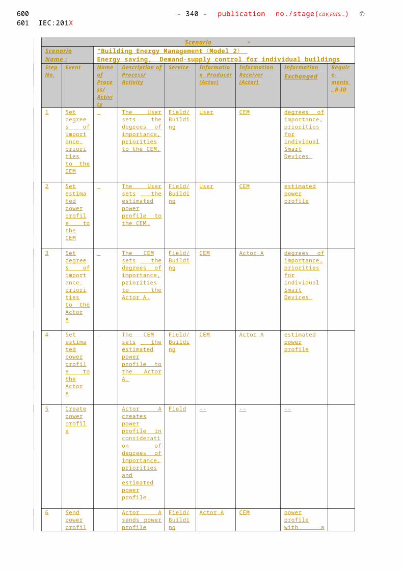
– 340 – publication no./stage(CDV,FDIS...) IEC:201X
A.4.21
HIGH LEVEL USE CASE (WGSP211x) Exchanging information on consumption, price and warnings with external actors and within the home
Description of the Use Case
Name of Use Case
Use Case Identification
ID Domain(s) Name of Use Case
WGSP 2110
Smart Grid Exchanging information on consumption, price and warnings with external actors and within the home
Version Management
Version Management
Changes / Version
Date NameAuthor(s) or Committee
Domain Expert
Area of Expertise / Domain / Role
Title Approval Status
draft, for comments, for voting, f inal
0.2 01/03/2012
Willem Strabbing - The European Smart Meter Industry Group (ESMIG)
Tim Sablon - The European Smart Meter Industry Group (ESMIG)
Various contributions from Smart Grid Coordination Group members (version history will be included in the next version).
Domain expert
Editor
Initial draft
Draft
509510
4144
4145
4146
4147
4148
414941504151
4152
4153
4154
4155

Use Case Name: – 341 –Energy Flexibility Management
0.4 11/07/2012
Tim Sablon - The European Smart Meter Industry Group (ESMIG)
Editor Reviewed version
Version after commenting phase
0.5 12/11/2012 Tim Sablon - The European Smart Meter Industry Group (ESMIG)
Editor Reviewed version
Version for final commenting
Scope and Objectives of Use Case
Scope and Objectives of Use Case
Related business case A combination of the functions described in this use support “Demand Response”, following the definition of Eurelectric, which is referenced in the Sustainable Processes workgroup’s report.
Scope The scope of this use case is the communication between the CEM and "upstream"11 actors. The communication between CEM, the consumer and (in-home) smart devices is officially not in this scope of this report, but will be included in the use case description for the sake of clarity. Smart devices cover also smart appliances, generators and storage (see table with actors).
When the consumer has a price dependent energy tariff and/or a time dependent distribution tariff, price based demand response is enabled by creating an incentive for load management by consumers or a CEM in response to price changes (RTP, CPP, ToU). Note that multiple loads/generation resources (even from multiple premises) can be combined in the CEM to be mutually controlled.
From an architectural point of view the Smart Grid Coordination Group introduced the "Smart Grid Connection Point" (SGCP) entity as an interface between Smart Grid actors (applications and/or organizations) and in-home/building systems or devices. The diagram below shows the SGCP in its environment.
11 Upstream in this context means towards actor A or B (see actor definitions)
511512
4156
4157
513

– 342 – publication no./stage(CDV,FDIS...) IEC:201X
Please note that the boxes in the diagram above are functional. The Smart Meter and CEM can be one or two separate physical boxes. The CEM can also be integrated in Smart in-home devices. The communication with the Grid market/applications can be through one or through separate infrastructures.
Objective The objective of this use case is to exchange information between external actors and the premise in order to:
Make consumers aware of their energy consumption
Providing external market roles with information on (forecasted) energy consumption
Enable consumers or their Energy Management System to react on (changes in) energy prices, thus supporting consumers to optimize their consumption to use cheaper or greener energy (depending on personal preferences)
Send warnings to the consumer to keep consumption below a certain (contracted) level
Enable external actors to retrieve the state of in home smart devices
514515
4158

Use Case Name: – 343 –Energy Flexibility Management
Narrative of Use Case
Narrative of Use Case
Short description – max 3 sentences
This use case describes how information regarding price and environmental aspects is sent from upstream actors to CEM and how information regarding energy consumption or generation as well as smart device statuses are being sent back to the consumer and upstream actors.
Complete description
This high level use case comprises four different primary use cases:
WGSP 2111: Information regarding power consumption or generation
The Smart Meter makes available the information on total power consumption or generation in the house. The CEM receives this information but can also receive consumption / generation information per smart device. 12 The rate of update of the information must be proportional to the rate of change in the power drawn.
This use case scenario consists of two scenarios:
Sending information regarding (future) power consumption or generation of individual smart devices. This information is provided by the smart device to CEM, which may aggregate it and use it to forecast consumption/generation and send this to the display and external actors. As the CEM can be a function integrated in smart devices in the customer premises, more than one CEM in the house may execute this scenario. In this case, one CEM does not have the total house consumption, but only partial information.
Sending information regarding total power consumption or generation. This information is provided by the smart meter, sent to the CEM that may use it to make a forecast of consumption/generation and forward this to the display and external actors.
Note that several use case scenarios may work together in an iterative way. E.g. there might be a negotiation which uses the price (WGSP2112) to get a forecast (WGSP2111), then adapting the price, which might be binding from there on.
Also note that the consumption information can be transferred via different channels to actor A, B and to the consumer or in-home devices. This implies that the use case could effectively be split up into three sub-use cases, each with its own goal (sending the information to Actor A, sending the information to Actor B and sending the information to the Simple External Consumer Display).
WGSP 2112: Price and/or environmental information
Actor A will send information (e.g. price, meteorological, environmental, cost related information, warning signals) to the consumer or his smart devices via the Energy management gateway; Actor B may do the same via the Smart Metering gateway. The goal is to make the consumer or his devices aware of the amount and cost of consumed energy and the amount and income for selling energy back to the grid, or of other elements relevant to energy management (e.g.: the percentage amount of green power). The consumer can also receive a notification that the tariff has been changed.
12 Note that the CEM may be a function embedded in the Smart device (having thus access to only partial consumption information), in which case the information on total consumption is provided to the CEM by a communication with a gateway or the smart meter
516517
4159
518519520

– 344 – publication no./stage(CDV,FDIS...) IEC:201X
To move out peak loads, an external actor can propose a tariff of electricity higher during certain periods of the day or during certain days in order to invite his customers to delete or shift various uses or lower their consumptions in its housing during these periods. These periods and days may not be fixed in advance, but rather determined on the flexibility needs of the smart grid. When such a higher cost period occurs, the customers are notified in advance, so that they can be ready to react to these price signal s. Smart devices can be parameterised or managed by the CEM to start when the energy costs less or when the relative amount of green energy is over a set level or to temporarily lowers its power consumption and/or shifts its operation before or after a peak consumption period. The parameterization of the CEM and smart devices are the responsibility of the consumer.
The price information can be either real-time price, real time combined price and volume signal s or a fixed tariff schedule. Note that dynamic pricing requires a metering system that is able to provide the information for, or to calculate the cost of energy based on, a flexible tariff scheme. This implies that price related changes in the CEM by actor A or B may be combined with a tariff update in the smart meter; this is described in use case BI.03. of the Smart Meters Coordination Group use case repository.
The communication functionalities described in this use case may also be used to send warning messages from an external actor to the consumer, warning him that emergency load control will happen within a certain period of time, unless changes in consumption / generation take place.
Note that several use case scenarios may work together in an iterative way. E.g. there might be a negotiation which uses the price (WGSP2112) to get a forecast (WGSP2111), then adapting the price (WGSP2112), which might be binding from there on.
Also note that the information may be provided by Actor A or Actor B alternatively, which implies that this use case could be effectively split up in two sub-use cases.
WGSP 2113: Warning signal s from CEM / Smart Device
This primary use case scenario consists of two scenarios:
A warning signal is generated by the smart device after estimating that the power consumed during its next operation will exceed maximum contracted power.
The Smart Device receives information from the CEM on total house consumption and maximum contracted power. The Smart Device estimates the maximum power that will be consumed during its next operation (ex: cycle). If there is a risk to exceed the threshold of the maximum contracted power, a warning is generated and displayed on the smart device or other customer interfaces (e.g. other devices or the simple external consumer display). The threshold is based on limits received from the CEM, which can be limits for instant power or accumulated energy consumption.
The warning signal is generated by the CEM after noticing that contracted power is exceeded, based on information from the smart meter. Note that the CEM may also take action to lower the consumption of smart devices; since these actions are not in scope of this use case and the work of the SG-CG, this scenario only describes how the warning signal s are being sent.
The limits (for instant power) can include not only upper limits (for example, when the customer is close to the limit of his contracted power) but also lower limits (for example, the remaining usual instant power consumption when the customer is out or during night time).
521522

Use Case Name: – 345 –Energy Flexibility Management
WGSP 2114: Retrieve status of smart devices
This use case describes how an external actor retrieves the state of a smart device directly from the CEM. This real time information may be retrieved by en external actor who has a business relationship to the customer, having guaranteed that some of his smart devices are (exclusively) controlled by the external actor.
Another alternative is that the customer himself retrieves the state of smart devices via the display, in which case the information is not necessarily sent to actor A or B.
General Remarks
General Remarks
Diagrams of Use Case
Diagram of Use Case
See detailed description os use cases
Technical Details
Actors: People, Systems, Applications, Databases, the Power System, and Other Stakeholders
For the definition of this use case, the following architecture has been used as a basis.
523524
4160
4161
4162
4163
4164
41654166
4167
4168
4169

– 346 – publication no./stage(CDV,FDIS...) IEC:201X
Note that the actors in the above architecture are functional entities, which means that some of them may be part of the same physical device (e.g. CEM functionality may be part of a smart device, the smart meter might also encompass the smart metering gateway and CEM, etc…)
Actors
Grouping (Community) Group Description
Actor Name
see Actor List
Actor Type
see Actor List
Actor Description
see Actor List
Further information specific to this Use Case
Customer Energy Manager (CEM)
Internal The CEM is a logical function optimising energy consumption and or production based on signal s received from the grid, consumer’s settings and contracts, and devices minimum performance standards. The Customer Energy Manager collects messages sent to and received from connected devices; especially the in-home/building sector has to be mentioned. It can handle general or dedicated load and generation management commands and then forwards these to the connected devices. It provides vice versa information towards the “grid / market”. Note that multiple loads/generation resources can be combined in the CEM to be mutually controlled.
When the CEM is integrated with communication functionalities it is called a Customer Energy Management System or CEMS.
Energy management gateway
Internal An access point (functional entity) sending and receiving smart grid related information and commands between actor A and the CEM, letting the CEM decide
CEM Smart Device*
Simple external consumer
display
Actor AEnergy
management gateway (EMG)
Smart Metering gateway (LNAP )
Smart meter functionalityActor B
Energy Management / Providing Flexibility (M490)
M441 architecture
Market communication
* e.g. HBES device, smart appliances, storage, generator, domestic charger for EV, complex display
Smart Grid Connection
Point
Functional metering reference architecture according the SM-CG (TR50572)
525526
4170
417141724173
4174
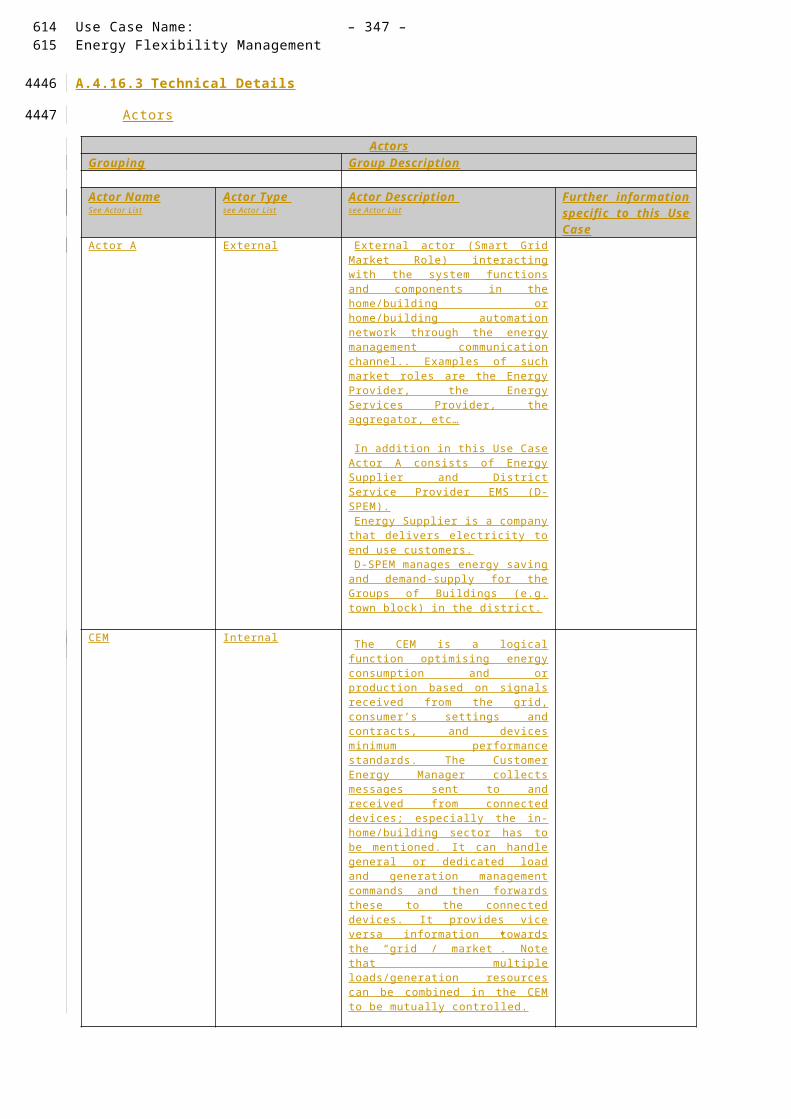
Use Case Name: – 347 –Energy Flexibility Management
how to process the events. The communication is often achieved through an internet connection of through a wireless connection.
This gateway may also provide services including protocol conversion, device management, security and service capabilities.
Smart Metering gateway (LNAP)
Internal An access point (functional entity) that allows access to one or more metering end devices and, when equipped with an interface, to advanced display / home automation end devices connected to the local network.
A LNAP also may allow data exchange between different functional entities connected to the same LN. The LNAP may act simply as a router transferring messages between the metering end device and/or display/home automation devices and the Neighbourhood network of wide area network.
It may also provide services including protocol conversion, device management, security and service capabilities. Services may be provided as functions of the LNAP itself or provide proxy services on behalf of limited capability devices connected to the local network.
Smart meter Internal The metering end device is a combination of the following meter-related functions from the Smart Metering reference architecture:
Metrology functions including the conventional meter display (register or index) that are under legal metrological control. When under metrological control, these functions shall meet the essential requirements of the MID;
One or more additional functions not covered by the MID. These may also make use of the display;
Meter communication functions.
NNAP Internal The Neighbourhood Network Access Point is a functional entity that provides access to one or more LNAP’s, metering end devices, displays and home automation end devices connected to the neighbourhood network (NN). It may allow data exchange between different functional entities connected to the same NN.
Simple external consumer display
External
Dedicated display screen in connection with the smart meter/SGCP available to the customer to check power consumption, planned load reductions and load reductions historical. Other not dedicated means also exist to deliver consumption information to the customer, such as the personal computer, the mobile phone or the TV set.
Smart device External
A smart device may be an appliance, generator or storage device (Local storage devices include direct and functional electricity storages such as electrochemical batteries, heat pumps and micro CHP such as fuel cells with heat buffers, air conditioning and
527528

– 348 – publication no./stage(CDV,FDIS...) IEC:201X
cooling devices with thermal inertia, etc…). The smart device can receive data directly from the grid, though an interface with the CEM and can react to commands and signal s from the grid in an intelligent way.
Since the smart device is outside the scope of the SGCG, it must be seen as an external actor
Smart appliance (white goods)
External
An example of a smart device is a smart white goods appliance which is an appliance that has the capability to act in response to a signal from the grid and thereby optimize its behaviour towards the energy supply network. The signal can be received from a utility or a third party energy service provider directly or via a home energy management system,
The signal can be information like the cost of energy or the amount of available renewable energy, or it can be a Demand Respond signal (delay load signal or other related information) that the appliance must receive, interpret and react upon based on pre-set or active consumer input. The smart appliance is not guaranteed to respond, but will do so based on its status and user settings in order to ensure the expected performance.
The consumer has the ultimate control of the appliance and can override any specific mode (e.g. override a delay to allow immediate operation, limit delays to no more than a certain number of hours, or maintain a set room temperature).
Any appliance operation settings or modes shall be easy for an average, non-technical consumer to activate or implement.
Actor A External
External actor (Smart Grid Market Role) interacting with the system functions and components in the home or home automation network through the energy management communication channel.. Examples of such market roles are the Energy Provider, the Energy Services Provider, the aggregator, etc…
HES Internal Responsible for acquiring the reads from meters and/or from data concentrators
Delivers the raw meter reads to MDM
Repeats the reading for any missing reads
Is the short-term interim data storage (1-3 months) for meter reads
Pushes the event information upwards to MDM
Supports the specific protocols of the concentrators and meters
Contains some topology information and aggregation functionality for plug & play solutions
MDM Internal Is the single meter data repository for all metering data
529530

Use Case Name: – 349 –Energy Flexibility Management
Is the long-term storage for the metering data
Ensures the data quality by VEE for the higher level business processes
Connects all head-end systems
Is the connection point for other systems to reach the smart meters i.e. a gateway to HES and back
Delivers the meter reads to other business systems for further usage
Acts as the critical security firewall between business and operational systems and the advanced metering infrastructure.
Contains some topology information and aggregation functionality
Actor B External
External actor (Smart Grid Market Role) interacting with the system functions and components in the home or home automation network through the metering communication channel. This actor is responsible for collecting metering data. Examples of such market roles are the DSO, metering company, etc.
Preconditions, Assumptions, Post condition, Events
Use Case Conditions
Actor/System/Information/Contract Triggering Event Pre-conditions Assumption
In order to correctly bill demand/generation flexibility, the smart meter and CEM need to be time synchronized
531532
4175
4176
4177
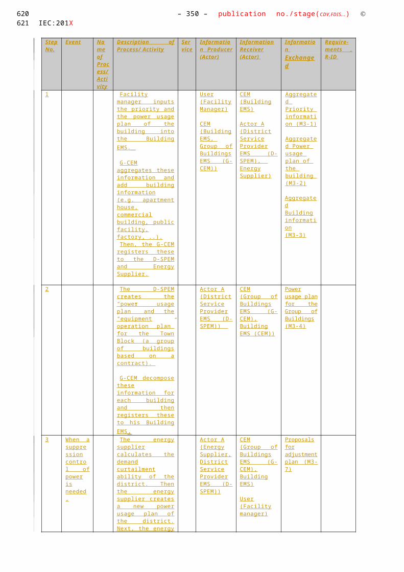
– 350 – publication no./stage(CDV,FDIS...) IEC:201X
References / Issues
References
No. References Type Reference Status Impact on Use Case
Originator / Organisation
Link
1 Example use cases to WGSP2111
EDF-0023, EDF-0024, EDF-0025, EDF-0026, CECED0003, ESMIG-0001, FINS0048 (3.4.2 p 25-26), FINS0077, FINS0081, FINS0082, FINS0089, FINS0090, TC205-0043, AK716.0.1_UC4, AK716.0.1_UC5
The original Use Cases that served as a basis for this Use Case
2 Example use cases to WGSP2112
CECED-0001, CECED-0002, CECED-0003, DKE-0014, EDF-0003, EDF-0016, EDF-0021, EDF-0027, ESMIG-0006, ESMIG0013, ESMIG-0014, FINS-0070, FINS-0071, PMA-0001, SCE-0001, TC205-0002 through -0012, AK716.0.1_UC4, AK716.0.1_UC5
The original Use Cases that served as a basis for this Use Case
3 Example use cases to WGSP2113
FINS0088 The original Use Cases that served as a basis for this Use Case
Further Information to the Use Case for Classification / Mapping
Classification Information
Relation to Other Use Cases
Flexibility cluster
Level of Depth
Primary use case
Prioritisation
1
533534
4178
4179
4180
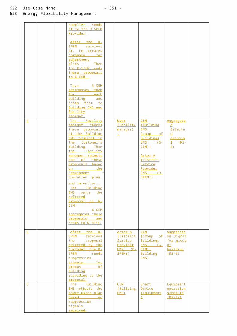
Use Case Name: – 351 –Energy Flexibility Management
Generic, Regional or National Relation
Generic
View
Technical
Further Keywords for Classification
Demand side management, demand response, Smart Grid
535536
4181

– 352 – publication no./stage(CDV,FDIS...) IEC:201X
Step by Step Analysis of Use Case
WGSP 2111: Use case scenario 1: Information regarding power consumption / generation / storage of individual smart devices
Scenario Conditions
No. Scenario Name
Primary Actor Triggering Event Pre-Condition Post-Condition
2111.1
Information regarding power consumption / generation / storage of individual smart devices
Smart device New consumption / generation / storage information is available in the smart device
Communication connection between all actors is established
The smart device has a schedule instructing it when to send consumption information to the CEM.
The CEM has a schedule instructing it when to send consumption information to the external actor / display.
(forecasted) consumption / generation is received by actor A and/or actor B and/or display
Diagram of use case
Diagram of Use Case
Actor B Actor A Smart deviceEnergy Management
Gateway
Information regarding power consumption / generation of individual smart devices
CEMSmart Metering Gateway (LNAP)
Display
Individual appliance consumption / generation information
Total or partial (forecasted) house consumption / generation
Total or partial (forecasted) house consumption / generation
Total or partial (forecasted) house consumption / generation
Total or partial (forecasted) house consumption / generation
Total or partial (forecasted) house consumption / generation
Alternative
Smart Meter
Total or partial (forecasted) house consumption / generationOptional
537538
4182
41834184
4185
4186

Use Case Name: – 353 –Energy Flexibility Management
Actor B Actor A Smart deviceEnergy Management
Gateway
Information regarding power consumption / generation of individual smart devices
CEMSmart Metering Gateway (LNAP)
Display
Individual appliance consumption / generation information
Total or partial (forecasted) house consumption / generation
Total or partial (forecasted) house consumption / generation
Total or partial (forecasted) house consumption / generation
Total or partial (forecasted) house consumption / generation
Total or partial (forecasted) house consumption / generation
Alternative
Smart Meter
Total or partial (forecasted) house consumption / generationOptional
539540
4187

– 354 – publication no./stage(CDV,FDIS...) IEC:201X
Steps – Normal
Scenario
Scenario Name
Provide flexibility:
Step No.
Event Name of Process/ Activity
Description of Process/ Activity
Zones / Domains
Information Producer (Actor)
Information Receiver (Actor)
Information Requirements , R-ID
Exchanged
1 New consumption / generation / storage information is available in the smart device
Smart device sends information regarding consumption to the CEM
Field / Customer premise
Smart device
CEM Individual device consumption / generation / storage
2 CEM received consumption / generation information per individual smart device
The CEM aggregates and/or forecasts consumption and sends this information to the Energy Management Gateway
Field / Customer premise
CEM Energy Management Gateway
Total or partial (forecasted) house consumption / generation / storage
3a Energy Management Gateway received (forecasted) consumption / generation
Energy Management Gateway forwards information Smart Metering Gateway (alternative)
Field / Customer premise
Energy Management Gateway
Smart Metering Gateway
Total or partial (forecasted) house consumption / generation / storage
3b Energy Management Gateway received (forecasted) consumption / generation
Energy Management Gateway forwards information to Actor A
(alternative)
Field - Enterprise / Customer premise
Energy Management Gateway
Actor A Total or partial (forecasted) house consumption / generation / storage
4 Smart Metering Gateway (LNAP) receives (forecasted) consumption / generation
Smart Metering Gateway (LNAP) sends information to the Smart Meter (optional)
Field / Customer premise
Smart Metering Gateway (LNAP)
Smart Meter
Total or partial (forecasted) house consumption / generation / storage
5 Smart Meter receives (forecasted) consumption / generation
Smart Meter sends information to the Display (optional)
Field / Customer premise
Smart Meter
Simple external consumer display
Total or partial (forecasted) house consumption / generation / storage
541542
4188

Use Case Name: – 355 –Energy Flexibility Management
6 Smart Metering Gateway (LNAP) receives (forecasted) consumption / generation
Smart Metering Gateway (LNAP) forwards information to Actor B (via the metering channel)
Field-Enterprise/Customer premise
Smart Metering Gateway (LNAP)
Actor B Total or partial (forecasted) house consumption / generation / storage
543544
4189

– 356 – publication no./stage(CDV,FDIS...) IEC:201X
WGSP 2111: Use case scenario 2: Information regarding total power consumption or generation
Scenario Conditions
No. Scenario Name
Primary Actor Triggering Event
Pre-Condition Post-Condition
2111.2
Information regarding total power consumption / generation
Smart Meter New consumption / generation information is available in the Smart Meter
Communication connection between all actors is established
The smart meter has a schedule instructing it when to send consumption information to the CEM.
The CEM has a schedule instructing it when to send consumption information to the external actor / display.
(forecasted) consumption/generation information is received by actor A and/or or Actor B and/or display
Diagram of use case
Diagram of Use Case
545546
41904191
4192
4193

Use Case Name: – 357 –Energy Flexibility Management
Actor A Smart deviceEnergy Management
Gateway
CEMSmart Metering Gateway (LNAP)
Display
Information regarding total power consumption
Forecased house consumption
Total and/or forecased house consumption
Total and/or forecased house consumption
Total and/or forecased house consumption
Alternative
Total house consumption
Total house consumption
Smart Meter
Total and/or forecased house consumption
Actor B
Total house consumption
Optional
547548
4194

– 358 – publication no./stage(CDV,FDIS...) IEC:201X
Steps – Normal
Scenario
Scenario Name
Provide flexibility:
Step No.
Event Name of Process/ Activity
Description of Process/ Activity
Zones / Domains
Information Producer (Actor)
Information Receiver (Actor)
Information Requirements , R-ID
Exchanged
1 New consumption/ generation information is available in the Smart Meter
The Smart Meter forwards the consumption information to the Smart Metering Gateway (LNAP)
Field / Customer premise
Smart Meter
Smart Metering Gateway (LNAP)
Consumption information
2 Smart Metering Gateway (LNAP) receives the information
Smart Metering Gateway (LNAP) forwards the consumption information to Energy Management Gateway
Field / Customer premise
Smart Metering Gateway (LNAP)
Energy Management Gateway
Consumption information
3 Energy Management Gateway receives the information
Energy Management Gateway forwards the consumption information to CEM
Field / Customer premise
Energy Management Gateway
CEM Consumption information
4 New consumption information is available in the CEM
The CEM may forecast total consumption and sends (forecasted) consumption information to the Energy Management Gateway
Field / Customer premise
CEM Energy Management Gateway
Total and/or forecasted house consumption
5a Energy Management Gateway received (forecasted) consumption
Energy Management Gateway forwards information to Actor A (alternative)
Field - enterprise/ Customer premise
Energy Management Gateway
Actor A Total and/or forecasted house consumption
5b Energy Management Gateway received (forecasted) consumption
Energy Management Gateway forwards information to Smart Metering Gateway (LNAP) (alternative)
Field / Customer premise
Energy Management Gateway
Smart Metering Gateway (LNAP)
Total and/or forecasted house consumption
6 Smart Metering Gateway (LNAP)
Smart Metering Gateway (LNAP) forwards information to Smart Meter
Smart Metering Gateway (LNAP)
Smart Meter
Total and/or forecasted house
549550
4195

Use Case Name: – 359 –Energy Flexibility Management
receives (forecasted) consumption
(optional) consumption
7 Smart Meter receives (forecasted) consumption
Smart Meter forwards information to Display (optional)
Smart Meter
Simple external consumer display
Total and/or forecasted house consumption
8 Smart Metering Gateway (LNAP) receives (forecasted) consumption
Smart Metering Gateway (LNAP) forwards information to Actor B (via metering channel)
Field-Enterprise / Customer premise
Smart Metering Gateway (LNAP)
Actor B Total and/or forecasted house consumption
551552
4196

– 360 – publication no./stage(CDV,FDIS...) IEC:201X
WGSP 2112: Price and environmental information
Scenario Conditions
No. Scenario Name
Primary Actor Triggering Event Pre-Condition Post-Condition
2112
Price and environmental information
Actor A or actor B New price and environmental information is available in Actor A or Actor B
Communication connection between all actors is established
Price and environmental information is received by Smart Devices
Diagram of use case
Diagram of Use Case
Steps – Normal
Scenario
Scenario Name
Provide flexibility:
Step No.
Event Name of Process/
Description of Process/ Activity
Zones / Domains
Information Producer (Actor)
Information Receiver (Actor)
Information Requirements , R-
Exchanged
Actor B Actor A Smart Devices
Energy Management
Gateway
CEMSmart Metering Gateway (LNAP)
Display
Price & environmental information
Price and environmental information
Price and environmental information
Price and environmental information
Price and environmental information
New price and environmental information
Alternative
New price and environmental information
Smart Meter
Price and environmental information
Alternative
Optional
553554
4197
4198
4199
4200
4201

Use Case Name: – 361 –Energy Flexibility Management
Activity
ID
1a New price and/or environmental is available in actor B (alternative)
Actor B sends price and/or environmental information to Smart Metering Gateway (LNAP) (via metering channel)
Enterprise - Field/ Customer premise
Actor B Smart Metering Gateway (LNAP)
Price and/or environmental information
1b Smart Metering Gateway (LNAP) receives information
Smart Metering Gateway (LNAP) forwards price and/or environmental information to Energy Management Gateway
Field / Customer premise
Smart Metering Gateway (LNAP)
Energy Management Gateway
Price and/or environmental information
1c Smart Metering Gateway (LNAP) receives information
Smart Metering Gateway (LNAP) forwards price and/or environmental information to Smart Meter
Field / Customer premise
Smart Metering Gateway (LNAP)
Smart Meter
Price and/or environmental information
1d Smart Meter receives information
Smart Meter forwards price and/or environmental information to Display
Field / Customer premise
Smart Meter
Simple external consumer display
Price and/or environmental information
2 New price and/or environmental is available in actor A (alternative)
Actor A sends information to Energy Management Gateway
Enterprise – field /customer premise
Actor A Energy Management Gateway
Price and/or environmental information
3 Energy Management Gateway received information
Energy Management Gateway forwards price and/or environmental information to CEM
Field/ customer premise
Energy Management Gateway
CEM Price and/or environmental information
4 CEM received new price and/or environmental information
CEM identifies relevant Smart Devices and forwards the new price and/or environmental information to the Smart Devices
Field / Customer premise
CEM Smart Appliciances
Price and/or environmental information
WGSP 2113: use case scenario 1: Warning signal s from Smart devices
Scenario Conditions
No. Scenario Name
Primary Actor Triggering Event Pre-Condition Post-Condition
555556
4202
4203

– 362 – publication no./stage(CDV,FDIS...) IEC:201X
2113.1
Warning signal s based on individual devices consumption
Smart device The CEM received information on a new operation to be executed
The subscribed power limits are made known to the smart device
Information on total consumption is available in the CEM
Warning signal is received by display and/or smart devices
557558
4204

Use Case Name: – 363 –Energy Flexibility Management
Diagram of use case
Diagram of Use Case
Steps – Normal
Scenario
Scenario Name
Provide flexibility:
Step No.
Event Name of Process/ Activity
Description of Process/ Activity
Zones / Domains
Information Producer (Actor)
Information Receiver (Actor)
Information Requirements , R-ID
Exchanged
1 The CEM received information on a new operation to be executed
The CEM sends information on total house consumption and subscribed power to the device involved
Field / Customer premise
CEM Smart device
Total house consumption and subscribed power
2 The smart device received information on total house consumption and subscribed power to the device
The smart device estimates the maximum power tobe consumed for the operation and deducts this from the available power. In case there is insufficient power available, it displays a warning message and sends a warning message to the
Field / Customer premise
Smart Device
CEM Warning message
CEM Smart Devices Smart Meter
Warning signals based individual appliances consumption
Warning signal
Information on total consumption& subscribed power
Warning signal
Display
Warning signal
Smart MeteringGateway (LNAP)
Warning signal
Warning signalParallel
Energy management gateway
Warning signal
Optional
559560
4205
4206
4207

– 364 – publication no./stage(CDV,FDIS...) IEC:201X
CEM
3a The CEM received a warning message
The CEM sends the warning message to (other) smart devices
Field / Customer premise
CEM Smart Device
Warning message
3b The CEM received a warning message
The CEM sends the warning message to the Energy Management Gateway
Field / Customer premise
CEM Energy Management Gateway
Warning message
4 Energy Management Gateway receives the warning message
Energy Management Gateway forwards message to the Smart Metering Gateway (LNAP)
Field / Customer premise
Energy Management Gateway
Smart Metering Gateway (LNAP)
Warning message
5 The Smart Metering Gateway (LNAP) receives the warning message
Smart Metering Gateway (LNAP) forwards message to the Smart Meter
Field / Customer premise
Smart Metering Gateway (LNAP)
Smart Meter
Warning message
6 The Smart Meter receives the warning message
Smart Meter sends the message to the Display
Field / Customer premise
Smart Meter
Simple external consumer display
Warning message
WGSP 2113: use case scenario 2: Warning signal s from the CEM
Scenario Conditions
No. Scenario Name
Primary Actor Triggering Event Pre-Condition Post-Condition
2113.2
Warning signal s based on total house consumption from smart meter
Smart meter Smart meter is triggered to send consumption information to CEM
The subscribed power limits are know to the CEM
Smart meter has a schedule indicating when to send consumption information to CEM
Warning signal is received by display and/or smart devices
Diagram of use case
Diagram of Use Case
561562
4208
4209
4210
4211

Use Case Name: – 365 –Energy Flexibility Management
CEM Smart Devices Smart Meter
Warning signals based total house consumption information from smart meter
Warning signal
Display
Warning signal
Smart MeteringGateway (LNAP)
Warning signal
Warning signalParallel
Energy management gateway
Warning signal
Total house consumption
Total house consumption
Total house consumption
Optional
563564
4212

– 366 – publication no./stage(CDV,FDIS...) IEC:201X
Steps – Normal
Scenario
Scenario Name
Provide flexibility:
Step No.
Event Name of Process/ Activity
Description of Process/ Activity
Zones / Domains
Information Producer (Actor)
Information Receiver (Actor)
Information Requirements , R-ID
Exchanged
1 Smart meter is triggered to send consumption information to CEM
Smart meter sends information on total house consumption to smart metering gateway (LNAP)
Field / Customer premise
Smart meter
Smart metering gatway (LNAP)
Total house consumption
2 Smart metering gateway receives total house consumption
Smart metering gateway (LNAP) forwards information to energy management gateway
Field / Customer premise
Smart metering gatway (LNAP)
Energy management gateway
Total house consumption
3 Energy management gateway receives total house consumption
Energy management gateway forwards information to CEM
Field / Customer premise
Energy management gateway
CEM Total house consumption
4a CEM receives total house consumption and notices that maximum contracted power is being exceeded
The CEM sends warning message to smart devices
Field / Customer premise
CEM Smart Device
Warning message
4b CEM receives total house consumption and notices that maximum contracted power is being exceeded
The CEM sends warning message to the Energy Management Gateway
Field / Customer premise
CEM Energy Management Gateway
Warning message
5 Energy Management Gateway receives the warning message
Energy Management Gateway forwards message to the Smart Metering Gateway (LNAP)
Field / Customer premise
Energy Management Gateway
Smart Metering Gateway (LNAP)
Warning message
6 The Smart Metering Gateway (LNAP)
Smart Metering Gateway (LNAP) forwards message to the Smart Meter
Field / Customer premis
Smart Metering Gateway
Smart Meter
Warning message
565566
4213

Use Case Name: – 367 –Energy Flexibility Management
receives the warning message
e (LNAP)
7 The Smart Meter receives the warning message
Smart Meter sends the message to the Display
Field / Customer premise
Smart Meter
Simple external consumer display
Warning message
567568
4214

– 368 – publication no./stage(CDV,FDIS...) IEC:201X
WGSP 2114: Retrieve status of smart devices
Scenario Conditions
No. Scenario Name
Primary Actor Triggering Event Pre-Condition Post-Condition
4 Retrieve status of smart devices
Actor A or actor B Actor A or Actor B want to retrieve the state of a smart device
The external actor is authorized to retrieve the state of the selected smart device(s)
The external actor received the requested information
Diagram of use case
Diagram of Use Case
Steps – Normal
Scenario
Scenario Name
Provide flexibility:
Step No.
Event Name of Process/ Activity
Description of Process/ Activity
Zones / Domains
Information Producer (Actor)
Information Receiver (Actor)
Information
Requirements , R-ID Exchang
ed
Actor B Actor A Smart Devices
Energy Management
Gateway
CEMSmart Metering Gateway (LNAP)
Retrieve device status
Device state request
Device state request
Device status
Device state request
Device state request
Device status
Device state request
Device status
Device status
Device status
Alternative
569570
4215
4216
4217
4218
4219

Use Case Name: – 369 –Energy Flexibility Management
1a Actor A wants to retrieve the state of a smart device (Alternative)
Actor A sends a device state request to the energy management gateway
Enterprise – field /customer premise
Actor A Energy management gateway
Device state request
1b Actor B wants to retrieve the state of a smart device (Alternative)
Actor B sends a device state request to the Smart Metering Gateway (LNAP) (via metering channel)
Enterprise - Field / Customer premise
Actor B Smart Metering Gateway (LNAP)
Device state request
2 Smart Metering Gateway (LNAP) receives device state request
Smart Metering Gateway (LNAP) forwards device state request to Energy management gateway
Field / Customer premise
Smart Metering Gateway (LNAP)
Energy management gateway
Device state request
3 Energy management gateway receives device state request
Energy management gateway forwards device state request to CEM
Field/ customer premise
Energy management gateway
CEM Device state request
4 CEM receives device state request
The CEM retrieves the device state from its memory and sends it to the energy managent gateway
Optionally,the CEM may interrogate the relevant appliances on their current status
Field / Customer premise
CEM Energy management gateway
Device status
5a Energy management gateway receives device status
Energy management gateway forwards device status to Actor A (Alternative)
Field - Enterprise /customer premise
Energy management gateway
Actor A Device status
5b Energy management gateway receives device status
Energy management gateway forwards device status to A Smart Metering Gateway (LNAP) (Alternative)
Field - Enterprise /customer premise
Energy management gateway
Smart Metering Gateway (LNAP
Device status
6 Smart Metering Gateway (LNAP) receives device status
Smart Metering Gateway (LNAP) forwards device status to Actor B (via metering channel)
Field – Enterprise / customer premise
Smart Metering Gateway (LNAP)
Actor B Device status
571572
4220

– 370 – publication no./stage(CDV,FDIS...) IEC:201X
Steps – Alternative, Error Management, and/or Maintenance/Backup Scenario
Scenario
Scenario Name :
Provide flexibility:
Step No.
Event Name of Process/Activity
Description of Process /Activity
Service
Information Producer
Information Receiver
Information
Requirements, R-ID
Exchanged
573574
4221
4222

Use Case Name: – 371 –Energy Flexibility Management
Information Exchanged
Information Exchanged
Name of Information Exchanged Description of Information Exchanged
Requirements to information data R-ID
Consumption / generation / storage information
Total or partial, actual or forecasted
Price and/or environmental information
Confirmation
Information regarding subscribed power
Warning message
Device state request
Device status
Common Terms and Definitions
Common Terms and Definitions
Term Definition
Notes and open issues
Notes and open issues
Nr Note
1. This high level use case may in the future be split up in two high level use cases:
-upstream communication (consumption, device status)
- downstream and within home communication (price)
2. Where relevant all primary use case (scenarios) may be split up according to external actors
3. There is not yet a use case covering the situation where there would be multiple CEMs and the aggregation takes place in the grid side of the SGCP. (e.g. how is the user being informed that he is (going to) exceed his contractual power). Closing this gap would be a next step
575576
4223
4224
4225
4226
4227

– 372 – publication no./stage(CDV,FDIS...) IEC:201X
4. Next step: define additonal use cases using the top down method, considering the functional architecture as a black box and identifying which messages would go in / come out
577578
4228

Use Case Name: – 373 –Energy Flexibility Management
HIGH LEVEL USE CASE (JWG-HLUC1.1 )Flexible start of a Smart Device (SD)
Description of the Use Case
Name of Use Case
Use Case Identification
ID Domain(s)/ Zone(s)
Name of Use Case
JWG-HLUC1.1
Domain: Customer Premises, DER
Zones:
Process, Field, Station
SD consumes / generates energy on a flexible basis (High Level Use Case or Generic Use Case)
Version Management
Version Management
Changes / Version
Date NameAuthor(s) or Committee
Domain Expert
Area of Expertise / Domain / Role
Title/Changes Approval Status
draft, for comments, for voting, f inal
0.3 Jan.06, 2014
Stephan Fertig (CLC TC59x WG7)
Editor Update HLUC to fit Joint Use Case Workshop description
Draft
0.2 Dec.06, 201
Stephan Fertig (CLC TC59x WG7)
Editor Updated Version after CLC TC59x discussions
Draft
0.1 Nov.04, 2013
Stephan Fertig (CLC TC59x WG7)
Editor Initial Draft Draft
579580
42294230
4231
4232
4233
4234
4235
Stephan Fertig, 17/01/14,
Correct – see my comment in my email.
Katsuyoshi Naka, 17/01/14,
Is the JWG-HLUC1.1 high level description of JWG-UC1 shown in 7.3.2 ?

– 374 – publication no./stage(CDV,FDIS...) IEC:201X
Scope and Objectives of Use Case
Scope and Objectives of Use Case
Scope In some cases Smart Devices provide flexibility towards their time. The device can manage its flexible running times by itself and communicates them to the CEM on a negotiation basis.
Utilizing flexibility by a CEM must be negotiated and confirmed with the smart device. The flexible operation of a Smart Device does not imply a specific optimization strategy. It depends on the control algorithm which the customer defines for its Smart Device and the CEM.
The scope of that High Level Use Case deals with the basic information exchange between a Smart Device and the CEM to allow a flexible start. Also it covers the information exchange on the energy consumption during operation to allow an energy scheduling within the CEM.
Objective(s) This use case defines the basic information which is required to offer flexible start of Smart Devices.
There are various optimization targets possible for setting a flexible start time.
Related business case(s)
Demand Response (DR)
Demand Side Management (DSM)
Narrative of Use Case
Narrative of Use Case
Short description
The User activates a specific profile on the Smart Device that allows a flexible start. The Smart Device then starts a negotiation process with the CEM to find the most suitable start time. The interaction between the SD and the CEM does not require user interaction and operates autonomously. The SD fulfils the job according to the activated profile and might ask the user for final confirmation. After job completion the end customer might get notified on successful or failed commissioning.
A Smart Device might have two basic operational modes:
Power Consumption by using electricty
Power Producing by generating electricity
Complete description
The User activates a specific action profile on the Smart Device. The Smart Device then negotiates a start time with the CEM based on the selected specifification. Such specification might include user specific requirements like pre-defined end-time, maximum energy consumption, or something else and device specific capabilities. Such a profile can be very simple and defines a setting for a specific purpose.
The interaction between the SD and the CEM does not require user interaction and operates
581582
4236
4237
4238
Stephan Fertig, 01/17/14,
Yes – the user is a customer. I will modify the term and shorten the description to three sentences.
Katsuyoshi Naka, 01/17/14,
I guess that “User” and “Customer” is same Actor. It had better use same Actor name.
Katsuyoshi Naka, 17/01/14,
According to IEC TC8 templete, short description of each use case is limited to sentences to maximum 3 sentences, I guess.
Stephan Fertig, 17/01/14,
See my comment in the email I have sent to you.
Katsuyoshi Naka, 17/01/14,
The scope of this HLUC does not deal with the information between grid and customer premises, is it right?

Use Case Name: – 375 –Energy Flexibility Management
autonomously. It is up to the SD to find the best possible solution according to the user defined operational mode. The SD visualizes relevant information to the User if possible and starts action in cooperation with the CEM. Once the User activates a profile on flexible start time of a smart device, the User hands over the control to the CEM or Smart Device.
The SD fulfils the job according to the activated profile of the user and notifies the User on successful or failed commissioning. A notification and visualization method of relevant information varies on the appliances that are used.
This Use Case comprises three primary use cases:
JWG- SPUC 1.1 : SD informs CEM about flexible star t
The Smart Device informs the CEM about its flexibility and limitations.
JWG-SPUC1.2 : CEM informs SD about starting time
The CEM coordinates an optimized starting according to the selected operational strategy. It might require consideration of more than one smart device for calculating a suitable start time.
JWG-SPUC1. 3 : CEM informs SD about slot shift
The calculated start which had been sent to the Smart Device by the CEM requires an update. There might be a change in the environment which requires the CEM to recalculate a new start time (within the pre-defined limits of the affected Smart Devices).
General Remarks
General Remarks
This High Level Use Case or Generic Use Case considers smart devices like home appliances (white goods, brown goods and consumer electronics).
Any communication between SD and CEM must provide acknowledge handling on application level and basic failure detection. A broken communication link shall not lead to an unsecure and critical situation. Therefore, Smart Devices must provide device specific fail-safe mechanisms to prevent danger from the customer (e.g. a cleaning process of an oven with very high temperatures shall not lead to a critical situation in the home if communication fails).
Diagrams of Use Case
Diagram of Use Case
See detailed description of use cases
583584
4239
4240
4241
4242
4243
Stephan Fertig, 01/17/14,
It is described earlier in the document and mean “specialized use case”.
Katsuyoshi Naka, 01/17/14,
What is SPUC? (Specific Primary Use Cases?)

– 376 – publication no./stage(CDV,FDIS...) IEC:201X
Technical Details
Actors: People, Systems, Applications, Databases, the Power System, and Other Stakeholders
For the definition of this use case, the following architecture has been used as a basis.
Note that the actors in the above architecture are functional entities, which means that some of them may be part of the same physical device (e.g. CEM functionality may be part of a smart device, the smart meter might also encompass the smart metering gateway and CEM, etc…).
Please consider that the scope of this high level use does not require all actors shown on the figure above. Following table shows involved actors.
Actors
Grouping (Community) Group Description
Actor Name
see Actor List
Actor Type
see Actor List
Actor Description
see Actor List
Further information specific to this Use Case
Customer Energy Manager
Internal The CEM is a logical function optimising energy consumption and or production based on signal s received from the grid, consumer’s settings and contracts, and devices minimum performance standards. The Customer Energy Manager collects messages sent to and received from connected devices; especially the in-home/building sector has to
CEM Smart Device*
Simple external consumer
display
Actor AEnergy
management gateway (EMG)
Smart Metering gateway (LNAP )
Smart meter functionalityActor B
Energy Management / Providing Flexibility (M490)
M441 architecture
Market communication
* e.g. HBES device, smart appliances, storage, generator, domestic charger for EV, complex display
Smart Grid Connection
Point
Functional metering reference architecture according the SM-CG (TR50572)
585586
4244
42454246
4247
4248
424942504251
4252
42534254
4255

Use Case Name: – 377 –Energy Flexibility Management
be mentioned. It can handle general or dedicated load and generation management commands and then forwards these to the connected devices. It provides vice versa information towards the “grid / market”. Note that multiple loads/generation resources can be combined in the CEM to be mutually controlled.
When the CEM is integrated with communication functionalities it is called a Customer Energy Management System or CEMS
Smart device External
A smart device may be an appliance, generator or storage device (Local storage devices include direct and functional electricity storages such as electrochemical batteries, heat pumps and micro CHP such as fuel cells with heat buffers, air conditioning and cooling devices with thermal inertia, etc…). The smart device can receive data directly from the grid, though an interface with the CEM and can react to commands and signal s from the grid in an intelligent way.
Since the smart device is outside the scope of the SGCG, it must be seen as an external actor
Smart appliance (white goods)
External
An example of a smart device is a smart white goods appliance which is an appliance that has the capability to act in response to a signal from the grid and thereby optimize its behaviour towards the energy supply network. The signal can be received from a utility or a third party energy service provider directly or via a home energy management system,
The signal can be information like the cost of energy or the amount of available renewable energy, or it can be a Demand Respond signal (delay load signal or other related information) that the appliance must receive, interpret and react upon based on pre-set or active consumer input. The smart appliance is not guaranteed to respond, but will do so based on its status and user settings in order to ensure the expected performance.
The consumer has the ultimate control of the appliance and can override any specific mode (e.g. override a delay to allow immediate operation, limit delays to no more than a certain number of hours, or maintain a set room temperature).
Any appliance operation settings or modes shall be easy for an average, non-technical consumer to activate or implement.
Actor A External
External actor (Smart Grid Market Role) interacting with the system functions and components in the home or home automation network through the energy management communication channel.. Examples of such market roles are the Energy Provider, the Energy Services Provider, the aggregator, etc…
Actor B External
External actor (Smart Grid Market Role) interacting with the system functions and components in the home or home automation network through the metering communication channel. This actor is responsible for collecting metering data. Examples of such market
587588

– 378 – publication no./stage(CDV,FDIS...) IEC:201X
roles are the DSO, metering company, etc.
User External
The end customer who has acquired a smart device. The end customer is responsible for configuring and setting operation mode of the Smart Device.
589590
4256

Use Case Name: – 379 –Energy Flexibility Management
Triggering Event, Preconditions, Assumptions
Use Case Conditions
Actor/System/Information/Contract
Triggering Event Pre-conditions Assumption
SD
Activation Signal SD is active and operational.
User has created or selected a profile before creating the event. SD starts negotiations with CEM based on the profile.
References
References
No. References Type
Reference Status Impact on Use Case
Originator / Organisation Link
1 Guideline Basic definitions and common procedures
Final Terms and definitions
SG-CG Sustainable Processes WG
ftp://ftp.cen.eu/EN/EuropeanStandardization/HotTopics/SmartGrids/Sustainable Processes.pdf
2 Technical Report
User Story and Sequence diagrams
Draft Major impact on Scenario
IEC TC57 / CLC TC205 / CLC /TC59x
-
3 Standard Use Case Template
Draft (FDIS)
Template desctription
IEC TC8 -
Further Information to the Use Case for Classification / Mapping
Classification Information
Relation to Other Use Cases
Level of Depth
High Level Use Case
Prioritisation
591592
4257
4258
4259
4260
4261
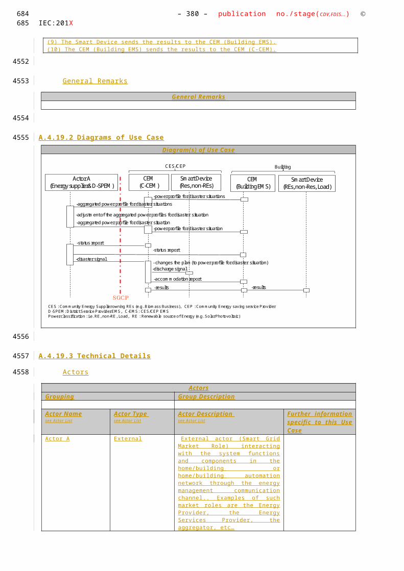
– 380 – publication no./stage(CDV,FDIS...) IEC:201X
Generic, Regional or National Relation
Generic High Level Use Case which can be applied to any kind of Smart Device.
Viewpoint
This High Level Use Case has the User perspective and the interaction of the SD with an overall energy management system. It does not consider market mechanisms for flexibility offering or power grid specific implementations.
Further Keywords for Classification
Generic High Level Use Case
593594
4262
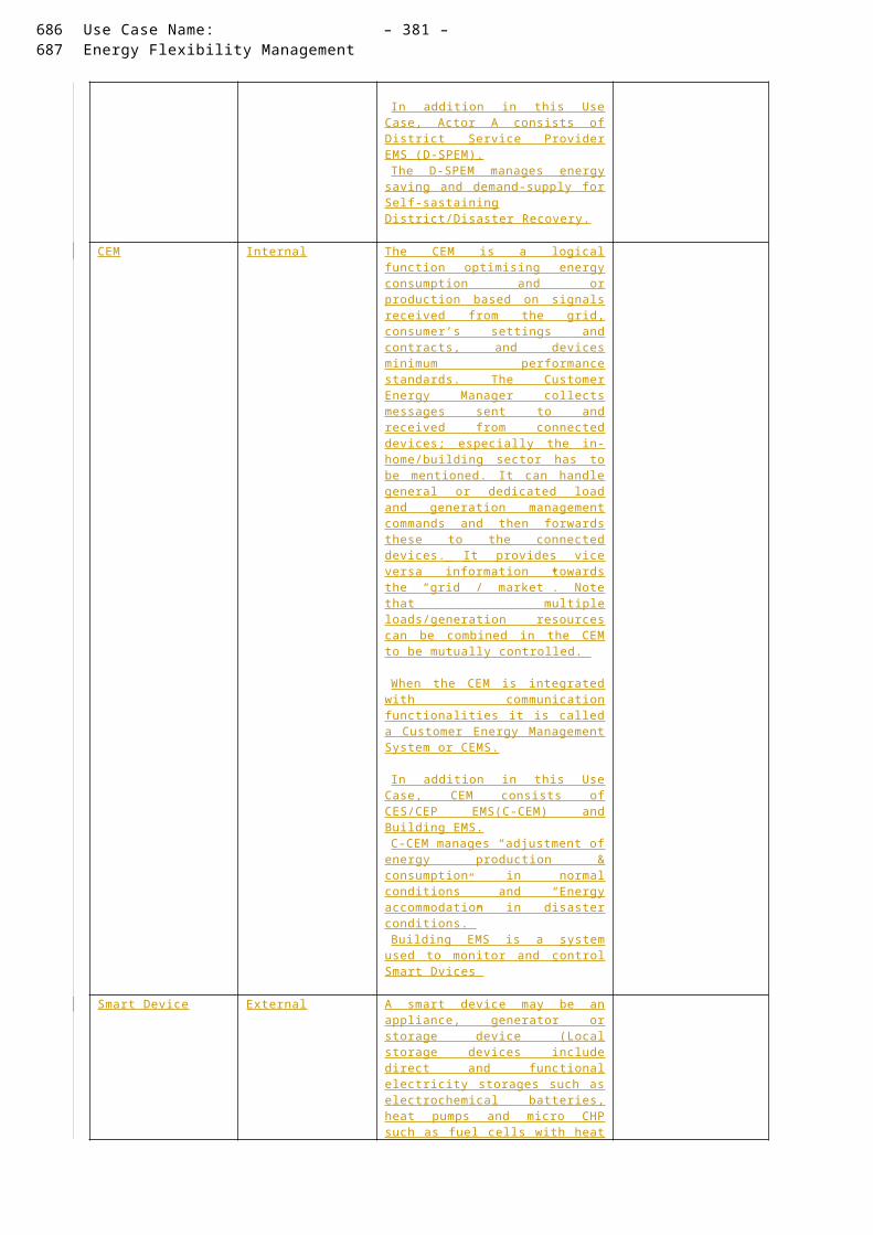
Use Case Name: – 381 –Energy Flexibility Management
Step by Step Analysis of Use Case
Steps – Scenario Name
Scenario Conditions
No. Scenario Name
Primary Actor Triggering Event Pre-Condition Post-Condition
Steps – Scenarios
Scenario
Scenario Name :
No. 1 - Flexible start time of appliance
Step No.
Event Name of Process/ Activity
Description of Process/ Activity
Service Information Producer (Actor)
Information Receiver (Actor)
Information Requirements , R-ID
Exchanged
1 - Preparation
User prepares SD for operation.
Preparation
User SD Device Specific (Door Closed, Water tap connected, Gas burner connected, electrical heating connected, …)
2 - Operation mode preparation
User enters settings for operational mode
Profile Generation/Selection
User SD Device and Customer Specific Data
3 Activation Signal
Operation Mode Activation
Pre-defined or manually entered setting become active on SD
Service Activation
User SD General Device Data (Activation)
4 SD Notification
SD informs CEM
SD sends activation profile to CEM.
Notification of User request to CEM
SD CEM Profile
5 Negotiation
CEM/SD Negotiatio
CEM and SD
Schedule
SD/CEM CEM/SD Device and Customer
595596
4263
4264
4265
4266

– 382 – publication no./stage(CDV,FDIS...) IEC:201X
n negotiate on flexible start time
Planning
Specific Data
6 User Information
Visualization
SD notifies the User on the schedule
Information delivery
SD User Profile
597598
4267

Use Case Name: – 383 –Energy Flexibility Management
Information Exchanged
Information Exchanged
Name of Information (ID)
Description of Information Exchanged Requirements to information data
Device Specific Data (DSD)
Device specific data can be classified to each product family like dish washer, washing machine, heating unit, etc.
This set of data is specific to the category of the SD. A SD might have multiple device specific data sets when combining multiple features.
Such information is sensitive in a way that any modification might change certain behaviour of a SD. That is crucial for CEM-SD negotiations.
Therefore, the communication must be protected from misuse and external influences.
Customer Specific Data (CSD)
The user who operates might be able to create a profile for customer specific information. Depending on the SD the data set might contain SLAs with energy providers, comfort settings, Customer habits, etc .
A SD can maintain one or more customer specific data sets.
CSD contains sensitive information. Such a data set might contain SLAs and privacy relevant information. Therefore, such information must be handled with care and shall be accessible to relevant actors only. That includes, that the CEM shall not be able to access contract specific information which belong to third party service providers.
General Device Data (GDD)
Common information which is required from each SD like an ID, communication address, status information, etc.
This set of data is not specific to white, brown, or consumer goods.
GDD provide common standardized functionalities which are the lower limit for enabling
Such information is sensitive in a way that any modification might turn on or off a SD.
Therefore, the communication must be protected from misuse and external influences.
Energy Profile An energy profile defines characteristics towards s specific operational mode which is applicable to the Smart Device.
Such information can be used for power consumption but also power generation.
The energy profile does not contain sensitive data in a way that it gives indication on the used Energy for a specific operational mode.
Requirements (optional)
599600
4268
4269
4270
Stephan Fertig, 17/01/14,
Yes.
Katsuyoshi Naka, 17/01/14,
What is “SLAs” ? Service Level Agreement?
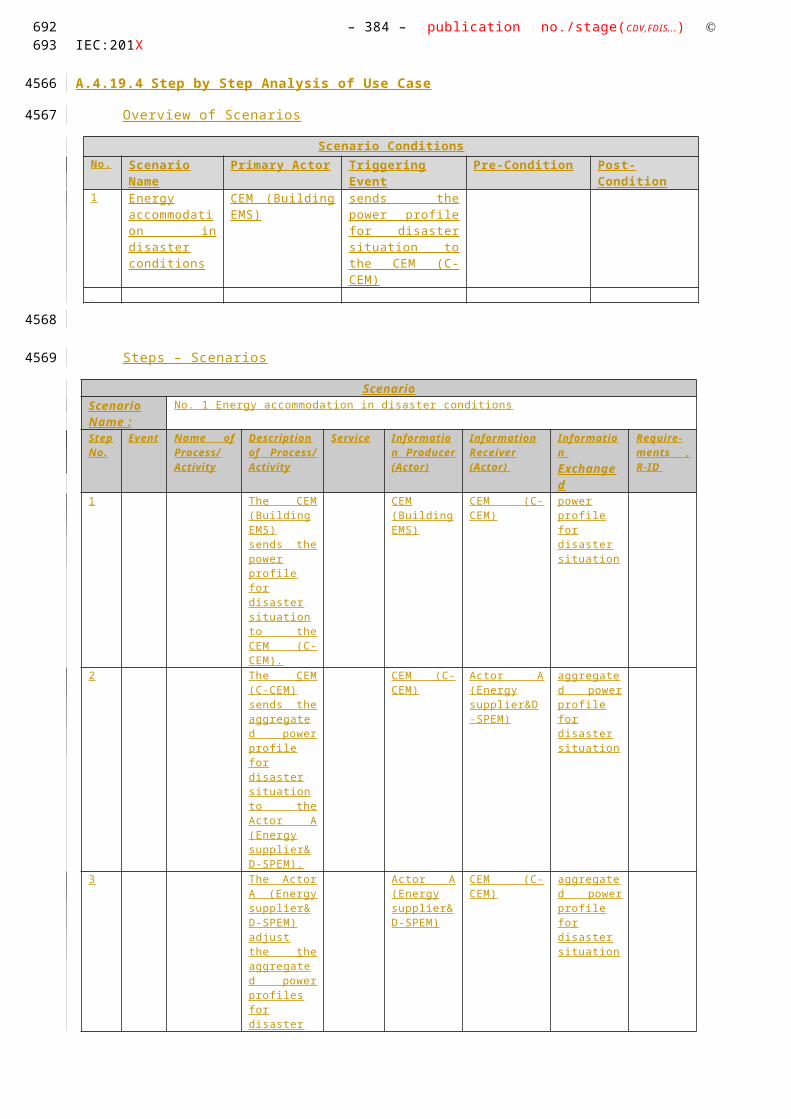
– 384 – publication no./stage(CDV,FDIS...) IEC:201X
Common Terms and Definitions
Common Terms and Definitions
Term Definition
Energy Profile An energy profile defines the power consumption/generation over time. The power might vary on the smart device which will be captured and visualized by the energy profile.
An energy profile might be split into multiple time slots. Such time slots have a fix amount of power to get a discrete power consumption/generation profile. A simple energy profile will contain only one power value and its duration.
Custom Information (optional)
Custom Information (optional)
Key Value Refers to Section
601602
4271
4272
4273

Use Case Name: – 385 –Energy Flexibility Management
SPECIFIC USE CASE (JWG-SPUC1.1) SD informs CEM about flexible start
Description of the Use Case
Name of Use Case
Use Case Identification
ID Domain(s)/ Zone(s)
Name of Use Case
JWG-SPUC1.1
Domain: Customer Premises, DER
Zones:
Process, Field, Station
SD informs CEM about flexible start (Specific Use Case or Primary Use Case)
Version Management
Version Management
Changes / Version
Date NameAuthor(s) or Committee
Domain Expert
Area of Expertise / Domain / Role
Title/Changes Approval Status
draft, for comments, for voting, f inal
0.1 Jan.06, 2014
Stephan Fertig (CLC TC59x WG7)
Editor Initial Draft Draft
Scope and Objectives of Use Case
Scope and Objectives of Use Case
Scope After a Smart Device was able to register at the CEM and works propoerly, it informs the CEM about its flexible start time.
Objective(s) This use case defines the basic information which is required to inform the CEM on a flexible start time.
Related business case(s)
Demand Response (DR)
603604
42744275
4276
4277
4278
4279
4280
4281

– 386 – publication no./stage(CDV,FDIS...) IEC:201X
Demand Side Management (DSM)
Narrative of Use Case
Narrative of Use Case
Short description
Complete description
General Remarks
General Remarks
Diagrams of Use Case
Diagram of Use Case
605606
4282
4283
4284
4285
4286
4287
4288

Use Case Name: – 387 –Energy Flexibility Management
Technical Details
Actors: People, Systems, Applications, Databases, the Power System, and Other Stakeholders
For the definition of this use case, the following architecture has been used as a basis.
Note that the actors in the above architecture are functional entities, which means that some of them may be part of the same physical device (e.g. CEM functionality may be part of a smart device, the smart meter might also encompass the smart metering gateway and CEM, etc…).
Please consider that the scope of this high level use does not require all actors shown on the figure above. Following table shows involved actors.
Actors
Grouping (Community) Group Description
Actor Name
see Actor List
Actor Type
see Actor List
Actor Description
see Actor List
Further information specific to this Use Case
Customer Energy Manager
Internal The CEM is a logical function optimising energy consumption and or production based on signal s received from the grid, consumer’s settings and contracts, and devices minimum performance standards. The Customer Energy Manager collects messages sent to and received from connected devices; especially the in-home/building sector has to
CEM Smart Device*
Simple external consumer
display
Actor AEnergy
management gateway (EMG)
Smart Metering gateway (LNAP )
Smart meter functionalityActor B
Energy Management / Providing Flexibility (M490)
M441 architecture
Market communication
* e.g. HBES device, smart appliances, storage, generator, domestic charger for EV, complex display
Smart Grid Connection
Point
Functional metering reference architecture according the SM-CG (TR50572)
607608
4289
42904291
4292
4293
429442954296
4297
42984299
4300

– 388 – publication no./stage(CDV,FDIS...) IEC:201X
be mentioned. It can handle general or dedicated load and generation management commands and then forwards these to the connected devices. It provides vice versa information towards the “grid / market”. Note that multiple loads/generation resources can be combined in the CEM to be mutually controlled.
When the CEM is integrated with communication functionalities it is called a Customer Energy Management System or CEMS
Smart device External
A smart device may be an appliance, generator or storage device (Local storage devices include direct and functional electricity storages such as electrochemical batteries, heat pumps and micro CHP such as fuel cells with heat buffers, air conditioning and cooling devices with thermal inertia, etc…). The smart device can receive data directly from the grid, though an interface with the CEM and can react to commands and signal s from the grid in an intelligent way.
Since the smart device is outside the scope of the SGCG, it must be seen as an external actor
Triggering Event, Preconditions, Assumptions
Use Case Conditions
Actor/System/Information/Contract
Triggering Event Pre-conditions Assumption
SD
Activation Signal SD is active and operational.
User has created or selected a profile before creating the event. SD starts negotiations with CEM based on the profile.
References
References
No. References Type
Reference Status Impact on Use Case
Originator / Organisation Link
1 Guideline Basic definitions and common procedures
Final Terms and definitions
SG-CG Sustainable Processes WG
ftp://ftp.cen.eu/EN/EuropeanStandardization/HotTopics/SmartGrids/Sustainable Processes.pdf
2 Generic Use Case
Additional Information
Final Additional information on
Smart Grid Coordination Group (SG-CG) Sustainable
-
609610
4301
4302
4303
4304

Use Case Name: – 389 –Energy Flexibility Management
Market communication
Processes WGSP2128
3 High Level Use Case
Direct relevance
Draft Terms and definitions
Joint Use Case Working Group (IEC TC57 WG21/ CLC TC205 WG18 / CLC TC59x WG7)
Further Information to the Use Case for Classification / Mapping
Classification Information
Relation to Other Use Cases
Level of Depth
Specific Level Use Case
Prioritisation
Generic, Regional or National Relation
Specific High Level Use Case which can be applied to any kind of Smart Device.
Viewpoint
This Specific Use Case has the User perspective and the interaction of the SD with an overall energy management system. It does not consider market mechanisms for flexibility offering or power grid specific implementations.
Further Keywords for Classification
Specific Use Case
Step by Step Analysis of Use Case
Steps – Scenario Name
Scenario Conditions
No. Scenario Name
Primary Actor Triggering Event Pre-Condition Post-Condition
Steps – Scenarios
Scenario
611612
4305
4306
4307
4308
4309

– 390 – publication no./stage(CDV,FDIS...) IEC:201X
Scenario Name :
No. 1 - Flexible start time of appliance
Step No.
Event Name of Process/ Activity
Description of Process/ Activity
Service Information Producer (Actor)
Information Receiver (Actor)
Information Requirements , R-ID
Exchanged
1 Activation Signal
Operation mode preparation
The CEM or the User activate a specific operational mode on a Smart device.
Preparation
User/CEM SD Device Specific (Button Pressed, Request from CEM to ask for flexibility, Timer on the SD, SD internal state change, …)
2 - SD calculates its capabilities
There might be various possibilities depending on the state and its operational mode which must be evaluated of the SD.
Preparation
SD SD -
3 SD Notification
SD informs CEM
SD sends the information of the flexible start to the CEM.
Flexibility Service offering
SD CEM Start Time, End Time Energy Profile (estimated energy consumption)
Information Exchanged
Information Exchanged
Name of Information (ID)
Description of Information Exchanged
Requirements to information data
Customer specific virtual energy counter.
Customer Specific Data (CSD) As defined for CSD within JWG-HLUC1.1 .
Customer Identification
Customer Specific Data (CSD) As defined for CSD within JWG-HLUC1.1 .
613614
4310
4311
Stephan Fertig, 17/01/14,
This information is part of the CSD (customer specific data set). To capture customer specific information, CSD is like a container for any of these information. The virtual customer specific energy counter came up through following example scenario:A shared washing machine captures energy consumption by each user. That implies no real dedicated meter and does not have impact on the classic utility owned meter. Each user of an apartment can then identify its energy costs.
Katsuyoshi Naka, 17/01/14,
This information equals to CSD, is it right ? Same comments for the other Information defined in this table.

Use Case Name: – 391 –Energy Flexibility Management
Latest possible end time
General Device Data (GDD) As defined for GDD within JWG-HLUC1.1 .
Latest possible start time
General Device Data (GDD) As defined for GDD within JWG-HLUC1.1 .
Estimated Energy Consumption
Energy Profile As defined for the Energy Profile within JWG-HLUC1.1 .
Common Terms and Definitions
Common Terms and Definitions
Term Definition
Energy Profile An energy profile defines the power consumption/generation over time. The power might vary on the smart device which will be captured and visualized by the energy profile.
An energy profile might be split into multiple time slots. Such time slots have a fix amount of power to get a discrete power consumption/generation profile. A simple energy profile will contain only one power value and its duration.
Custom Information (optional)
Custom Information (optional)
Key Value Refers to Section
615616
4312
4313
4314
4315
4316
4317
Stephan Fertig, 17/01/14,
Yes, It contains flexibility in energy consumption (power value) and time of use (duration)
Katsuyoshi Naka, 17/01/14,
The energy profile includes both estimated energy consumption per each slot and amount of flexibility per each slot, is it right ?

– 392 – publication no./stage(CDV,FDIS...) IEC:201X
SPECIFIC USE CASE (JWG-SPUC1.2) CEM informs SD about starting time
Description of the Use Case
Name of Use Case
Use Case Identification
ID Domain(s)/ Zone(s)
Name of Use Case
JWG-SPUC1.2
Domain: Customer Premises, DER
Zones:
Process, Field, Station
CEM informs SD about flexible start time (Specific Use Case or Primary Use Case)
Version Management
Version Management
Changes / Version
Date NameAuthor(s) or Committee
Domain Expert
Area of Expertise / Domain / Role
Title/Changes Approval Status
draft, for comments, for voting, f inal
0.1 Jan.06, 2014
Stephan Fertig (CLC TC59x WG7)
Editor Initial Draft Draft
Scope and Objectives of Use Case
Scope and Objectives of Use Case
Scope The CEM coordinates and calculates a best possible start time if a Smart Device offers flexibility. The strategy on how the optimization is not within the scope of this use case.
Once a CEM has identified a suitable start time for a Smart Device, that information must be shared.
Objective(s) The objective of that use case is to determine the required information exchange related to a start time delivery from CEM to SD.
617618
43184319
4320
4321
4322
4323
4324
4325

Use Case Name: – 393 –Energy Flexibility Management
Related business case(s)
Demand Response (DR)
Demand Side Management (DSM)
619620
4326

– 394 – publication no./stage(CDV,FDIS...) IEC:201X
Narrative of Use Case
Narrative of Use Case
Short description
The information exchange to tell a Smart Device when to start has limited options. Therefore, the information exchange on the expected start time is limited to transmitting a timestamp with the corresponding.
Complete description
The Smart Device had sent all flexibility related information already to the CEM. The CEM coordinates with other devices and has the capability to optimize according to the user’s need.
The expected start time shall be enough in the future that the CEM can ensure proper operation. In case of having a CEM somewhere on the internet, delay times must be considered and fail safe operation shall not be harmed.
The expected time to be transmitted might have absolute time format or relative time format. However, time synchronization is an important issue and the implementation has to take care that safety and security constraints are met.
General Remarks
General Remarks
Diagrams of Use Case
Diagram of Use Case
621622
4327
4328
4329
4330
4331

Use Case Name: – 395 –Energy Flexibility Management
623624
4332

– 396 – publication no./stage(CDV,FDIS...) IEC:201X
Technical Details
Actors: People, Systems, Applications, Databases, the Power System, and Other Stakeholders
For the definition of this use case, the following architecture has been used as a basis.
Note that the actors in the above architecture are functional entities, which means that some of them may be part of the same physical device (e.g. CEM functionality may be part of a smart device, the smart meter might also encompass the smart metering gateway and CEM, etc…).
Please consider that the scope of this high level use does not require all actors shown on the figure above. Following table shows involved actors.
Actors
Grouping (Community) Group Description
Actor Name
see Actor List
Actor Type
see Actor List
Actor Description
see Actor List
Further information specific to this Use Case
Customer Energy Manager
Internal The CEM is a logical function optimising energy consumption and or production based on signal s received from the grid, consumer’s settings and contracts, and devices minimum performance standards. The Customer Energy Manager collects messages sent to and received from connected devices; especially the in-home/building sector has to
CEM Smart Device*
Simple external consumer
display
Actor AEnergy
management gateway (EMG)
Smart Metering gateway (LNAP )
Smart meter functionalityActor B
Energy Management / Providing Flexibility (M490)
M441 architecture
Market communication
* e.g. HBES device, smart appliances, storage, generator, domestic charger for EV, complex display
Smart Grid Connection
Point
Functional metering reference architecture according the SM-CG (TR50572)
625626
4333
43344335
4336
4337
433843394340
4341
43424343
4344

Use Case Name: – 397 –Energy Flexibility Management
be mentioned. It can handle general or dedicated load and generation management commands and then forwards these to the connected devices. It provides vice versa information towards the “grid / market”. Note that multiple loads/generation resources can be combined in the CEM to be mutually controlled.
When the CEM is integrated with communication functionalities it is called a Customer Energy Management System or CEMS
Smart device External
A smart device may be an appliance, generator or storage device (Local storage devices include direct and functional electricity storages such as electrochemical batteries, heat pumps and micro CHP such as fuel cells with heat buffers, air conditioning and cooling devices with thermal inertia, etc…). The smart device can receive data directly from the grid, though an interface with the CEM and can react to commands and signal s from the grid in an intelligent way.
Since the smart device is outside the scope of the SGCG, it must be seen as an external actor
Triggering Event, Preconditions, Assumptions
Use Case Conditions
Actor/System/Information/Contract
Triggering Event Pre-conditions Assumption
References
References
No. References Type
Reference Status Impact on Use Case
Originator / Organisation Link
1 Guideline Basic definitions and common procedures
Final Terms and definitions
SG-CG Sustainable Processes WG
ftp://ftp.cen.eu/EN/EuropeanStandardization/HotTopics/SmartGrids/Sustainable Processes.pdf
2 Generic Use Case
Additional Information
Final Additional information on Market communication
Smart Grid Coordination Group (SG-CG) Sustainable Processes WGSP2128
-
627628
4345
4346
4347
4348

– 398 – publication no./stage(CDV,FDIS...) IEC:201X
3 High Level Use Case
Direct relevance
Draft Terms and definitions
Joint Use Case Working Group (IEC TC57 WG21/ CLC TC205 WG18 / CLC TC59x WG7)
Further Information to the Use Case for Classification / Mapping
Classification Information
Relation to Other Use Cases
Level of Depth
Specific Level Use Case
Prioritisation
Generic, Regional or National Relation
Specific High Level Use Case which can be applied to any kind of Smart Device.
Viewpoint
This Specific Use Case has the User perspective and the interaction of the SD with an overall energy management system. It does not consider market mechanisms for flexibility offering or power grid specific implementations.
Further Keywords for Classification
Specific Use Case
Step by Step Analysis of Use Case
Steps – Scenario Name
Scenario Conditions
No. Scenario Name
Primary Actor Triggering Event Pre-Condition Post-Condition
Steps – Scenarios
Scenario
629630
4349
4350
4351
4352
4353
4354
4355

Use Case Name: – 399 –Energy Flexibility Management
Scenario Name :
No. 1 - Flexible start time of appliance
Step No.
Event Name of Process/ Activity
Description of Process/ Activity
Service Information Producer (Actor)
Information Receiver (Actor)
Information Requirements , R-ID
Exchanged
1 Activation Signal
Operation mode preparation
The CEM or the User activates a specific operational mode on a Smart device.
Preparation
User/CEM SD Device Specific (Button Pressed, Request from CEM to ask for flexibility, Timer on the SD, SD internal state change, …)
2 - SD calculates its capabilities
There might be various possibilities depending on the state and its operational mode which must be evaluated of the SD.
Preparation
SD SD -
3 SD Notification
SD informs CEM
SD sends the information of the flexible start to the CEM.
Flexibility Service offering
SD CEM Start Time, End Time Energy Profile (estimated energy consumption)
631632
4356

– 400 – publication no./stage(CDV,FDIS...) IEC:201X
Information Exchanged
Information Exchanged
Name of Information (ID)
Description of Information Exchanged
Requirements to information data
Assigned start time
General Device Data (GDD) As defined for GDD within JWG-HLUC1.1 .
Common Terms and Definitions
Common Terms and Definitions
Term Definition
Custom Information (optional)
Custom Information (optional)
Key Value Refers to Section
633634
4357
4358
4359
4360
4361
4362
4363

Use Case Name: – 401 –Energy Flexibility Management
SPECIFIC USE CASE (JWG-SPUC1.1) CEM informs SD about slot shift
To be added
635636
43644365
4366

– 402 – publication no./stage(CDV,FDIS...) IEC:201X
HIGH LEVEL USE CASE (WGSP2120) Direct load / generation management
Description of the Use Case
Name of Use Case
Use Case Identification
ID Domain(s) Name of Use Case
WGSP 2120
Smart Grid Direct load / generation management
Version Management
Version Management
Changes / Version
Date NameAuthor(s) or Committee
Domain Expert
Area of Expertise / Domain / Role
Title Approval Status
draft, for comments, for voting, f inal
0.2 01/03/2012
Willem Strabbing - The European Smart Meter Industry Group (ESMIG)
Tim Sablon - The European Smart Meter Industry Group (ESMIG)
Various contributions from Smart Grid Coordination Group members (version history will be included in the next version).
Domain expert
Editor
Initial draft
Draft
0.4 11/07/2012
Tim Sablon - The European Smart Meter Industry Group (ESMIG)
Editor Reviewed version
Version after commenting phase
0.5 13/11/2012
Tim Sablon - The European Smart Meter Industry Group (ESMIG)
Editor Reviewed version
Version for final commenting
637638
43674368
4369
4370
4371
4372
4373

Use Case Name: – 403 –Energy Flexibility Management
Scope and Objectives of Use Case
Scope and Objectives of Use Case
Related business case Demand Side Management signal s are sent to the Consumer Energy Manager (CEM) to trigger a program that manages load by interacting with a number of in-home smart devices connected to the CEM.
T he functions described below can be labeled as a “Direct load control” use case, following the definition of Eurelectric, which is referenced in the Sustainable Processes Workgroup’s report
The difference with Use Case 2110 (supporting Demand Response) is that the operator responsible for managing the load/generation flexibility actively asks to change consumption/generation with a specific amount. The consumer’s reaction to this request, however is depending on the contract between the consumer and the organisation sending out the signal and the final decision made by the consumer or the device receiving the signal .
Scope The scope of this use case is the communication between the CEM and "upstream"13 actors. The communication between CEM, the consumer and (in-home) smart devices (e.g. appliances / generators / storage) is officially not in this scope of this report, but will be included in the Use Case description for the sake of clarity. Smart devices cover also smart appliances, generators and storage (see table with actors).
Note that multiple loads/generation resources (even from multiple premises) can be combined in the CEM to be mutually controlled.
From an architectural point of view the Smart Grid Coordination Group introduced the "Smart Grid Connection Point" (SGCP) entity as an interface between Smart Grid actors (applications and/or organizations) and in-home/building systems or devices. The diagram below shows the SGCP in its environment.
Please note that the boxes in the diagram above are functional. The Smart Meter and CEM can be one or two separate physical boxes. The
13 Upstream in this context means towards actor A or B (see actor definitions)
639640
4374
641

– 404 – publication no./stage(CDV,FDIS...) IEC:201X
CEM can also be integrated in Smart in-home devices. The communication with the Grid market/applications can be through one or through separate infrastructures.
Objective The objective of this use case is to manage in-home devices in order to control power consumption or generation resources for example to:
Avoid the risk of black out
React to real time peak power signal s
Balance the load between consumption and local production
Optimize the consumption to use cheaper and/or greener energy (depending on personal preferences)
Maintain power quality
642643
4375

Use Case Name: – 405 –Energy Flexibility Management
Narrative of Use Case
Narrative of Use Case
Short description – max 3 sentences
Signal s and metrological information are provided to the home/building via an interface called the Smart Grid Connection Point (SGCP). The following signal s can be distinguished:
Direct - load / generation / storage management
Emergencies
Emergency load control
Announce end of emergency load control
T he functions described below can be labeled as a “Direct load control” use case, following the definition of Eurelectric, which is referenced in the Sustainable Processes workgroup’s report.
Complete description
This Use Case comprises three primary use cases:
WGSP 2121 : Load / generation / storage management
A load/generation management signal is sent by an upstream actor to increase, reduce or limit the load, generation or stored energy.
A load/generation management signal is sent from actor A or B to the CEM. The CEM can forward the signal directly to the appliance/generator/storage or it may (based on a number of parameters) translate it into individual control signal s to the smart devices that were found to best suited to fulfill the operation. A smart device may be an appliance, generator or storage device (e.g. storage batteries, heat pumps, fuel cells, etc... ).
Based on the load management signal from the CEM, the smart device may change the power consumption, generation or storage depending on the kind of device, what the device is currently doing and the consumer settings. The start of the device may also be shifted in order to avoid taking energy during the peak time or to avoid exceeding a set power limit or may shift the activation of certain features.
The CEM may provide feedback to the external actor requesting the load/generation change, so this actor can have an idea of which change in consumption/generation to expect and to update his demand/generation forecast. The feedback may also be used for billing purposes
WGSP 2122: Emergencies
When there is a risk of a blackout in a given area, an emergency signal from actor A or B can request Smart devices to turn to network standby according to a safe procedure set by the manufacturer. The signal may or may not contain predefined time duration. The grid may also provide a signal notifying the end of the emergency and the return to normal status.
This use case describes the functionalities involved with emergencies from the home perspective. It shows how an emergency signal is sent to the home and how the CEM reacts to this. Use case “WGSP-2300 Emergency Demand Signal s - Load shedding” describes the emergency from the perspective of the external actor (e.g. DSO).
644645
4376

– 406 – publication no./stage(CDV,FDIS...) IEC:201X
Use case WGSP-2112 describes how warning messages may be sent from an external actor to the consumer, warning that emergency load control will happen within a certain period of time, unless changes in consumption / generation take place. This may typically precede WGSP-2122.
The primary use cases consist of two scenarios:
“Emergency load control” describes how a load control signal is sent through the CEM, to the devices. In case the emergency load control signal already contains the duration of the load control period, the CEM may instruct the smart devices at the right moment that the emergency period has passed. This last instruction is not in scope of this use case and is not described in the detailed analysis. Confirmations may optionally be sent from the CEM to Actor A/B so this actor can have an idea of which change in consumption/generation to expect and to update his demand/generation forecast. The feedback may also be used for billing purposes.
“Announce end of emergency load control” describes how an external actor instructs the CEM that the emergency period is ended. Confirmation from the CEM may be requested by the external actor to ensure that all CEM’s have received the message.
General Remarks
General Remarks
Diagrams of Use Case
Diagram of Use Case
See detailed description of use cases
Technical Details
Actors: People, Systems, Applications, Databases, the Power System, and Other Stakeholders
For the definition of this use case, the following architecture has been used as a basis.
646647
4377
4378
4379
4380
4381
4382
43834384
4385
4386

Use Case Name: – 407 –Energy Flexibility Management
Note that the actors in the above architecture are functional entities, which means that some of them may be part of the same physical device (e.g. CEM functionality may be part of a smart device, the smart meter might also encompass the smart metering gateway and CEM, etc…)
Actors
Grouping (Community) Group Description
Actor Name
see Actor List
Actor Type
see Actor List
Actor Description
see Actor List
Further information specific to this Use Case
Customer Energy Manager
Internal The CEM is a logical function optimising energy consumption and or production based on signal s received from the grid, consumer’s settings and contracts, and devices minimum performance standards. The Customer Energy Manager collects messages sent to and received from connected devices; especially the in-home/building sector has to be mentioned. It can handle general or dedicated load and generation management commands and then forwards these to the connected devices. It provides vice versa information towards the “grid / market”. Note that multiple loads/generation resources can be combined in the CEM to be mutually controlled.
When the CEM is integrated with communication functionalities it is called a Customer Energy Management System or CEMS
Energy management gateway
Internal An access point (functional entity) sending and receiving smart grid related information and commands between actor A and the CEM, letting the CEM decide
CEM Smart Device*
Simple external consumer
display
Actor AEnergy
management gateway (EMG)
Smart Metering gateway (LNAP )
Smart meter functionalityActor B
Energy Management / Providing Flexibility (M490)
M441 architecture
Market communication
* e.g. HBES device, smart appliances, storage, generator, domestic charger for EV, complex display
Smart Grid Connection
Point
Functional metering reference architecture according the SM-CG (TR50572)
648649
4387
438843894390
4391
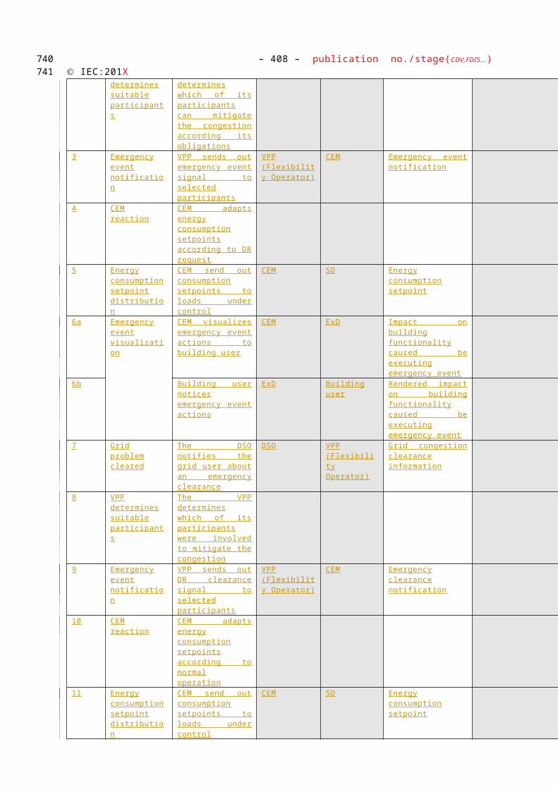
– 408 – publication no./stage(CDV,FDIS...) IEC:201X
how to process the events. The communication is often achieved through an internet connection of through a wireless connection.
This gateway may also provide services including protocol conversion, device management, security and service capabilities.
Smart Metering gateway (LNAP)
Internal An access point (functional entity) that allows access to one or more metering end devices and, when equipped with an interface, to advanced display / home automation end devices connected to the local network.
A LNAP also may allow data exchange between different functional entities connected to the same LN. The LNAP may act simply as a router transferring messages between the metering end device and/or display/home automation devices and the Neighbourhood network of wide area network.
It may also provide services including protocol conversion, device management, security and service capabilities. Services may be provided as functions of the LNAP itself or provide proxy services on behalf of limited capability devices connected to the local network.
Smart meter Internal The metering end device is a combination of the following meter-related functions from the Smart Metering reference architecture:
Metrology functions including the conventional meter display (register or index) that are under legal metrological control. When under metrological control, these functions shall meet the essential requirements of the MID;
One or more additional functions not covered by the MID. These may also make use of the display;
Meter communication functions.
NNAP Internal The Neighbourhood Network Access Point is a functional entity that provides access to one or more LNAP’s, metering end devices, displays and home automation end devices connected to the neighbourhood network (NN). It may allow data exchange between different functional entities connected to the same NN.
Simple external consumer display
External
Dedicated display screen in connection with the smart meter/SGCP available to the customer to check power consumption, planned load reductions and load reductions historical. Other not dedicated means also exist to deliver consumption information to the customer, such as the personal computer, the mobile phone or the TV set.
Smart device External
A smart device may be an appliance, generator or storage device (Local storage devices include direct and functional electricity storages such as electrochemical batteries, heat pumps and micro CHP such as fuel cells with heat buffers, air conditioning and
650651

Use Case Name: – 409 –Energy Flexibility Management
cooling devices with thermal inertia, etc…). The smart device can receive data directly from the grid, though an interface with the CEM and can react to commands and signal s from the grid in an intelligent way.
Since the smart device is outside the scope of the SGCG, it must be seen as an external actor
Smart appliance (white goods)
External
An example of a smart device is a smart white goods appliance which is an appliance that has the capability to act in response to a signal from the grid and thereby optimize its behaviour towards the energy supply network. The signal can be received from a utility or a third party energy service provider directly or via a home energy management system,
The signal can be information like the cost of energy or the amount of available renewable energy, or it can be a Demand Respond signal (delay load signal or other related information) that the appliance must receive, interpret and react upon based on pre-set or active consumer input. The smart appliance is not guaranteed to respond, but will do so based on its status and user settings in order to ensure the expected performance.
The consumer has the ultimate control of the appliance and can override any specific mode (e.g. override a delay to allow immediate operation, limit delays to no more than a certain number of hours, or maintain a set room temperature).
Any appliance operation settings or modes shall be easy for an average, non-technical consumer to activate or implement.
Actor A External
External actor (Smart Grid Market Role) interacting with the system functions and components in the home or home automation network through the energy management communication channel.. Examples of such market roles are the Energy Provider, the Energy Services Provider, the aggregator, etc…
HES Internal Responsible for acquiring the reads from meters and/or from data concentrators
Delivers the raw meter reads to MDM
Repeats the reading for any missing reads
Is the short-term interim data storage (1-3 months) for meter reads
Pushes the event information upwards to MDM
Supports the specific protocols of the concentrators and meters
Contains some topology information and aggregation functionality for plug & play solutions
MDM Internal Is the single meter data repository for all metering data
652653

– 410 – publication no./stage(CDV,FDIS...) IEC:201X
Is the long-term storage for the metering data
Ensures the data quality by VEE for the higher level business processes
Connects all head-end systems
Is the connection point for other systems to reach the smart meters i.e. a gateway to HES and back
Delivers the meter reads to other business systems for further usage
Acts as the critical security firewall between business and operational systems and the advanced metering infrastructure.
Contains some topology information and aggregation functionality
Actor B External
External actor (Smart Grid Market Role) interacting with the system functions and components in the home or home automation network through the metering communication channel. This actor is responsible for collecting metering data. Examples of such market roles are the DSO, metering company, etc.
654655
4392

Use Case Name: – 411 –Energy Flexibility Management
Preconditions, Assumptions, Post condition, Events
Use Case Conditions
Actor/System/Information/Contract Triggering Event Pre-conditions Assumption
In order to correctly bill demand/generation flexibility, the smart meter and CEM need to be time synchronized
References / Issues
References
No. References Type Reference Status Impact on Use Case
Originator / Organisation
Link
1 Example use cases to WGSP2121
DKE-0015, DKE0019 through DKE0021,EDF-0002, EDF-0003, EDF-0007, EDF0008, EDF-0009, EDF-0017, EDF-0022, ESMIG-0012, ESMIG-0013, ESMIG-0014, ESMIG-0017, FINS0048, FINS0074, FINS0078, FINS0080, FINS0083, FINS0084, FINS0085, FINS0086, FINS0087, PMA-0001, TC205-0019 through 0038, TC205-0044 through 0046, TC205-0048, AK716.0.1_UC1, AK716.0.1_UC3; CECED load shedding.
The original Use Cases that served as a basis for this Use Case
2 Example use cases to WGSP2122
FINS0048, FINS0085 The original Use Cases that served as a basis for this Use Case
Further Information to the Use Case for Classification / Mapping
Classification Information
Relation to Other Use Cases
Flexibility cluster
Level of Depth
656657
4393
4394
4395
4396
4397

– 412 – publication no./stage(CDV,FDIS...) IEC:201X
Primary use case
Prioritisation
1
Generic, Regional or National Relation
Generic
View
Technical
Further Keywords for Classification
Demand side management, direct load control, Smart Grid
658659
4398

Use Case Name: – 413 –Energy Flexibility Management
Step by Step Analysis of Use Case
WGSP 2121- Direct - load / generation / storage management
Scenario Conditions
No. Scenario Name Primary Actor Triggering Event Pre-Condition Post-Condition
2121 Direct - load / generation / storage management
Actor A or Actor B
Actor A or Actor B wants to send a load management signal to the market
Communication connection between all actors is established
The consumer configured the CEM and/or the participating devices. The consumer configured the device settings and thresholds
Information on total consumption or consumption per device is available in the CEM
The Smart device 14 executed the load management signal and Actor A or Actor B received feedback with a load curve recorded for this period
14 Smart device may be an appliance, generator or storage device (e.g. battery)
660661
4399
4400
4401
662

– 414 – publication no./stage(CDV,FDIS...) IEC:201X
Diagram of use case
Diagram of Use Case
Steps – Normal
Scenario
Scenario Name
Provide flexibility:
Step No.
Event Name of Process/ Activity
Description of Process/ Activity
Zones / Domains
Information Producer (Actor)
Information Receiver (Actor)
Information Requirements , R-ID
Exchanged
1a Actor A wants to send a load management signal to the market (alternative)
Actor A sends a load management signal to Energy Management Gateway
Enterprise – field / Customer premise
Actor A Energy Management Gateway
Load management signal
Actor B Actor A Smart devices
Energy Management
Gateway
DIRECT LOAD MANAGEMENT – smart device has end-decision about its load adjustmentCEMSmart Metering
Gateway (LNAP)Smart Meter
Load management signal
Start of load adjustment notification
Order of load adjustment
End of load adjustment
End of load adjustment notification
End of load adjustment period + sending load curve recorded for this period
Feedback status
Expected change in consumption
Load management signal
End of load adjustment period + sending load curve recorded for this period
Expected change in consumption
Display
Start of load adjustment notification
Load curve
Load curve
Load management signalLoad management signal
End of load adjustment notification
Load curve
Alternative
Optional
Alternative
Optional
Alternative
663664
4402
4403
4404

Use Case Name: – 415 –Energy Flexibility Management
1b Actor B wants to send a load management signal to the market (alternative)
Actor B sends a load management signal to Smart Metering Gateway (LNAP)
(via the metering channel)
Enterprise – Field / Customer premise
Actor B Smart Metering Gateway (LNAP)
Load management signal
2 Smart Metering Gateway (LNAP) receives the load management signal
Smart Metering Gateway (LNAP) forwards the load management signal to the Energy Management Gateway
Field/ Customer premise
Smart Metering Gateway (LNAP)
Energy Management Gateway
Load management signal
3 Energy Management Gateway receives a load management signal
Energy Management Gateway forwards the load management signal to CEM
Field/ Customer premise
Energy Management Gateway
CEM Load management signal
4 CEM receives load management signal
Optionally, when a notification needs to be displayed on the simple external consumer display, the CEM sends a notification to the Energy Management Gateway
Field/ Customer premise
CEM Energy Management Gateway
Start of load adjustment notification
5 Energy Management Gateway receives the load management signal
Energy Management Gateway sends the notification to Smart Meter
Field/ Customer premise
Energy Management Gateway
Smart Metering Gateway (LNAP
Start of load adjustment notification
6 Smart Metering Gateway (LNAP) receives the load management signal
Smart Metering Gateway (LNAP) sends the notification to Smart Meter
Field/ Customer premise
Smart Metering Gateway (LNAP
Smart Meter
Start of load adjustment notification
7 Smart Meter receives the load management signal
Smart Meter sends the start of load management notification to the Display
Field/ Customer premise
Smart Meter
Simple external consumer display
Start of load adjustment notification
8 CEM received the load management signal
CEM decides which smart devices need to be adjusted and sends an order of load adjustment to them
Field/ Customer premise
CEM Smart devices
Order of load adjustment
9 Smart devices receive the order of load adjustment
The Smart devices decide to switch on/off based on the consumer’s settings
Field/ Customer premis
Smart devices
CEM Load adjustment feedback
665666

– 416 – publication no./stage(CDV,FDIS...) IEC:201X
and send feedback to CEM
e
10 CEM receives feedback from smart devices
CEM informs Energy Management Gateway on which change in consumption to expect.
Field/ Customer premise
CEM Energy Management Gateway
Change in consumption
11a
Energy Management Gateway receives the change in consumption
Energy Management Gateway forwards the change in consumption to Actor A (alternative)
Field - enterprise/ Customer premise
Energy Management Gateway
Actor A Change in consumption
11b
Energy Management Gateway receives the change in consumption
Energy Management Gateway forwards the change in consumption to Smart Metering Gateway
Field - enterprise/ Customer premise
Energy Management Gateway
Smart Metering Gateway (LNAP)
Change in consumption
12 Smart Metering Gateway receives the change in consumption
Smart Metering Gateway forwards the change in consumption to Actor B (via the metering channel)
Field – Enterprise/ Customer premise
Smart Metering Gateway (LNAP)
Actor B Change in consumption
13 Load adjustment period is finished
CEM sends an end of load adjustment to Smart devices
Field/ Customer premise
CEM Smart devices
End of load adjustment
14 Smart devices receive the end of load adjustment from CEM
The Smart devices switch on/off and send feedback to CEM
Field/ Customer premise
Smart devices
CEM End of load adjustment feedback
15 CEM receives the feedback from Smart devices
CEMS sends load adjustment notification to the Energy Management Gateway
Field/ Customer premise
CEM Energy Management Gateway
End of load adjustment feedback
16 Energy Management Gateway receives feedback
Energy Management Gateway sends the end of load adjustment notification to the Smart Metering Gateway (LNAP)
Field/ Customer premise
Energy Management Gateway
Smart Metering Gateway (LNAP)
End of load adjustment notification
17 Smart Metering Gateway (LNAP) received notification
Smart Metering Gateway (LNAP) sends end of load adjustment notification to Smart Meter
Field/ Customer premise
Smart Metering Gateway (LNAP)
Smart Meter
End of load adjustment notification
18 Smart Meter received notification
Smart Meter sends the end of load adjustment
Field/ Customer
Smart Meter
Display End of load adjustment
667668

Use Case Name: – 417 –Energy Flexibility Management
notification to Display
premise
notification
19 Smart Meter received notification
Smart Meter sends the load curve recorded for this period to Smart Metering Gateway (LNAP)
Field/ Customer premise
Smart Meter
Smart Metering Gateway (LNAP)
Load curve
20 Smart metering gateway (LNAP) receives load curve
Smart metering gateway (LNAP) sends load curve to Energy Management Gateway
Field/ Customer premise
Smart Metering Gateway (LNAP)
Energy Management Gateway
Load curve
21 Energy Management Gateway receives load curve
Energy Management Gateway sends load curve to CEM
Field/ Customer premise
Energy Management Gateway
CEM Load curve
22 CEM receives load curve from smart meter
CEM sends the end of load adjustment period to Energy Management Gateway and sends a load curve recorded for this period
Field/ Customer premise
CEM Energy Management Gateway
Load adjustment feedback
23a
Energy Management Gateway receives the feedback
Energy Management Gateway forwards the feedback to Actor A (alternative)
Field - enterprise/ Customer premise
Energy Management Gateway
Actor A Load adjustment feedback
23b
Energy Management Gateway receives the feedback
Energy Management Gateway forwards the feedback to Smart Metering Gateway (LNAP) (alternative)
Field/ Customer premise
Energy Management Gateway
Smart Metering Gateway (LNAP)
Load adjustment feedback
24 Smart Metering Gateway (LNAP) receives the feedback
Smart Metering Gateway (LNAP) forwards the feedback to Actor B
(via the metering channel)
Field –- Enterprise/ Customer premise
Smart Metering Gateway (LNAP)
Actor B Load adjustment feedback
WGSP 2122: Use case scenario 1: Emergency load control
Scenario Conditions
No. Scenario Name
Primary Actor Triggering Event Pre-Condition Post-Condition
2122.1
Emergency load control
Actor A or Actor B
The need for an emergency
Communication between all actors
The CEM ordered all
669670
4405
4406
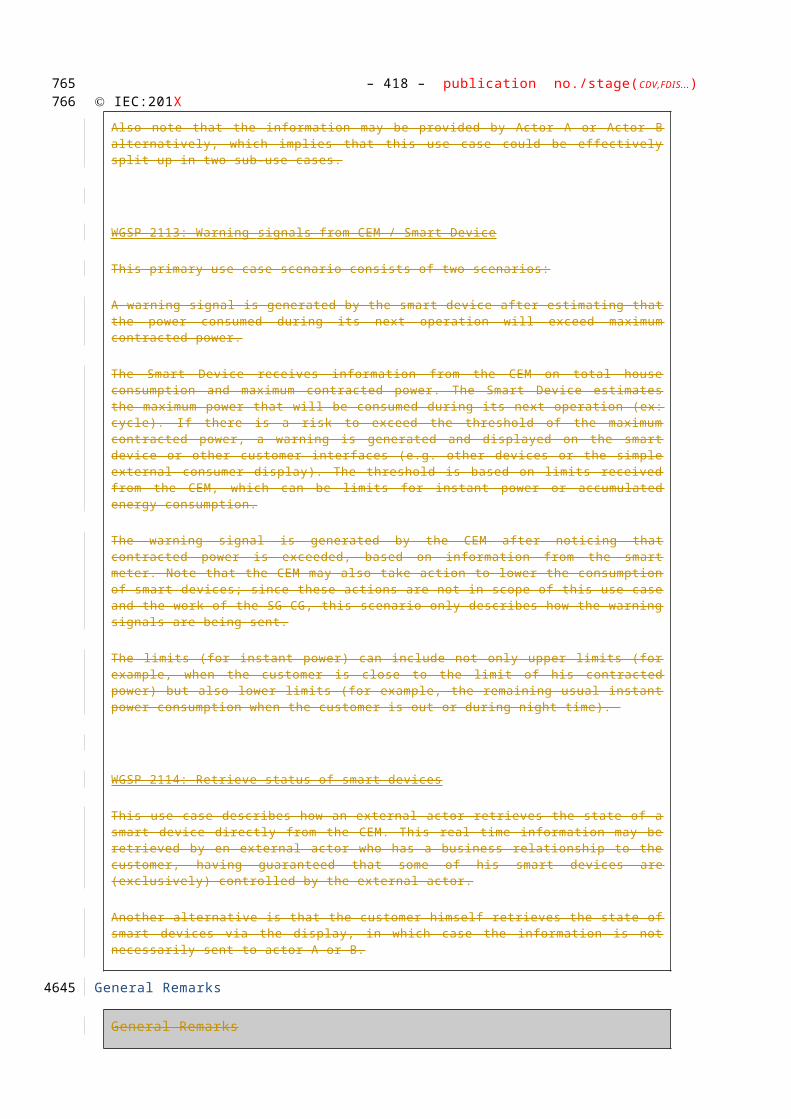
– 418 – publication no./stage(CDV,FDIS...) IEC:201X
reduction of power consumption / feed-in is identified
can be established smart devices to switch off and sent confirmation back to actor A or to the HES
Diagram of use case
Diagram of Use Case
Actor A Smart Devices
Energy Management
Gateway
Emergency load control
CEMSSmart Metering Gateway (LNAP)
Emergency load control command
ConfirmationConfirmation
Confirmation
ConfirmationConfirmation
Emergency signalEmergency signal
Emergency signalEmergency signal
Actor B
Alternative
Alternative
671672
4407
4408
4409

Use Case Name: – 419 –Energy Flexibility Management
Steps – Normal
Scenario
Scenario Name
Provide flexibility:
Step No.
Event Name of Process/ Activity
Description of Process/ Activity
Zones / Domains
Information Producer (Actor)
Information Receiver (Actor)
Information Requirements , R-ID
Exchanged
1a The need for an emergency reduction of power consumption / feed-in is identified
Actor A sends an emergency signal to the Energy Management Gateway (alternative)
Enterprise - field/ Customer premise
Actor A Energy Management Gateway
Emergency signal
1b The need for an emergency reduction of power consumption is identified
Actor B sends an emergency signal to the Smart metering gateway (LNAP (alternative) (via the metering channel)
Enterprise - Field/ Customer premise
Actor B Smart metering gateway (LNAP
Emergency signal
2 Smart Metering Gateway (LNAP) receives the emergency signal
Smart Metering Gateway (LNAP) sends emergeny signal to Energy Management Gateway
Field/ Customer premise
Smart metering gateway (LNAP)
Energy Management Gateway
Emergency signal
3 Energy Management Gateway receives the emergency signal
Energy Management Gateway forwards the emergency signal to CEM
Field/ Customer premise
Energy Mangement Gateway
CEM Emergency signal
4 CEM receives the emergency signal
CEM orders all smart devices to switch to network standby
Field/ Customer premise
CEM Smart devices
Emergency load management signal
5 Smart devices received emergency signal
Smart devices switch to network standby and optionally send confirmation back to CEM
Field/ Customer premise
Smart devices
CEM Confirmation (optional)
6 CEM receives confirmation
CEM optionally sends confirmation to Energy Management Gateway
Field/ Customer premise
CEM Energy Management Gateway
Confirmation (optional)
673674
4410

– 420 – publication no./stage(CDV,FDIS...) IEC:201X
5a Energy Management Gateway receives confirmation
Energy Management forwards confirmation to Actor A (Alternative)
Field - enterprise/ Customer premise
Energy Management Gateway
Actor A Confirmation (optional)
5b Energy Management Gateway receives confirmation
Energy Management forwards confirmation to Smart metering gateway (LNAP) (Alternative)
Field - enterprise/ Customer premise
CEM Smart metering gateway (LNAP)
Confirmation (optional)
6 Smart Metering Gateway (LNAP) receives confirmation
Smart metering gateway forwards confirmation to Actor B (Alternative) (via the metering channel)
Field - Enterprise/ operation Customer premise
Smart metering gateway (LNAP)
Actor B Confirmation (optional)
675676

Use Case Name: – 421 –Energy Flexibility Management
WGSP 2122: Use case scenario 2: Announce end of emergency load control
Scenario Conditions
No. Scenario Name
Primary Actor Triggering Event Pre-Condition Post-Condition
2122.2
Announce end of emergency load control
Actor A or Actor B
There is no more need for an emergency reduction of power consumption / feed-in
Communication between all actors can be established
The CEM informed all smart devices that the emergency load control period has ended and sent confirmation back to actor A or to the HES
Diagram of use case
Diagram of Use Case
Scenario
Scenario Name
Provide flexibility:
Step
Event Na Description of Zones / Informa Informati Information Re
Actor A Smart Devices
Energy Management
Gateway
Announce end of emergency load control
CEMSSmart Metering Gateway (LNAP)
End of emergency signal
Confirmation
Confirmation
ConfirmationConfirmation
End of emergency signalEnd of emergency signal
End of emergency signalEnd of emergency signal
Actor B
Alternative
Alternative
677678
4411
4412
4413
4414

– 422 – publication no./stage(CDV,FDIS...) IEC:201X
No. me of Process/ Activity
Process/ Activity Domains
tion Producer (Actor)
on Receiver (Actor)
quirements , R-ID
Exchanged
1a There is no more need for an emergency reduction of power consumption / feed-in
Actor A sends an end of emergency signal to the Energy Management Gateway (alternative)
Enterprise - field/ Customer premise
Actor A Energy Management Gateway
End of e mergency signal
1b There is no more need for an emergency reduction of power consumption / feed-in
Actor B sends an end of emergency signal to the Smart metering gateway (LNAP (alternative) (via the metering channel)
Enterprise - Field/ Customer premise
Actor B Smart metering gateway (LNAP
End of e mergency signal
2 Smart Metering Gateway (LNAP) receives the signal
Smart Metering Gateway (LNAP) sends end of emergeny signal to Energy Management Gateway
Field/ Customer premise
Smart metering gateway (LNAP)
Energy Management Gateway
End of e mergency signal
3 Energy Management Gateway receives the emergency
Energy Management Gateway forwards the end of emergency signal to CEM
Field/ Customer premise
Energy Mangement Gateway
CEM End of e mergency signal
4 CEM receives the end of emergency signal
CEM sends a message to smart devices, allowing them to operate in normal mode
Field/ Customer premise
CEM Smart devices
End of e mergency signal
5 CEM receives the end of emergency signal
CEM optionally onizationing a warning signal , initiator is smart meter tly in use to CEMSsends confirmation to Energy Management Gateway
Field/ Customer premise
CEM Energy Management Gateway
Confirmation (optional)
6a Energy Management Gateway receives confirmation
Energy Management forwards confirmation to Actor A (Alternative)
Field - enterprise/ Customer premise
Energy Management Gateway
Actor A Confirmation (optional)
6b Energy Management Gateway receives confirmation
Energy Management forwards confirmation to Smart metering gateway (LNAP) (Alternative)
Field - enterprise/ Customer premise
CEM Smart metering gateway (LNAP)
Confirmation (optional)
7 Smart Metering
Smart metering gateway forwards
Field - Enterpri
Smart meterin
Actor B Confirmation
679680

Use Case Name: – 423 –Energy Flexibility Management
Gateway (LNAP) receives confirmation
confirmation to Actor B (Alternative) (via the metering channel)
se/ operation Customer premise
g gateway (LNAP)
(optional)
681682
4415

– 424 – publication no./stage(CDV,FDIS...) IEC:201X
Steps – Alternative, Error Management, and/or Maintenance/Backup Scenario
Scenario
Scenario Name :
Provide flexibility:
Step No.
Event Name of Process/Activity
Description of Process /Activity
Service
Information Producer
Information Receiver
Information
Requirements, R-ID
Exchanged
Information Exchanged
Information Exchanged
Name of Information Exchanged Description of Information Exchanged
Requirements to information data R-ID
Load management signal This may include an economic value for the flexibility requested by Actor A/B
Start of load adjustment notification
Announcement of load adjustment
Order of load adjustment
Load adjustment feedback
Change in consumption
End of load adjustment
End of load adjustment feedback
End of load adjustment notification
Load curve
Load adjustment feedback
Emergency signal
683684
4416
4417
4418
4419

Use Case Name: – 425 –Energy Flexibility Management
Emergency load management signal
Confirmation A confirmation sent back to an external actor after receiving a load management signal may include:
an indication of the amount of load / generation that will be shifted
an indication that the CEM will comply with the request, without an estimate
End of emergency signal
Common Terms and Definitions
Common Terms and Definitions
Term Definition
Notes and open issues
Notes and open issues
Nr Note
1. A possible new primary use case on direct load control could describe how the grid asks which CEMs are willing to change consumption; grid receives offers and chooses which ones to accept. Developing this further may be a next step.
2. Where relevant all primary use case (scenarios) may be split up according to external actors
3. There is not yet a use case covering the situation where there would be multiple CEMs and the aggregation takes place in the grid side of the SGCP. (e.g. how is the user being informed that he is (going to) exceed his contractual power). Closing this gap would be a next step
4. Next step: define additonal use cases using the top down method, considering the functional architecture as a black box and identifying which messages would go in / come out
685686
4420
4421
4422
4423
4424
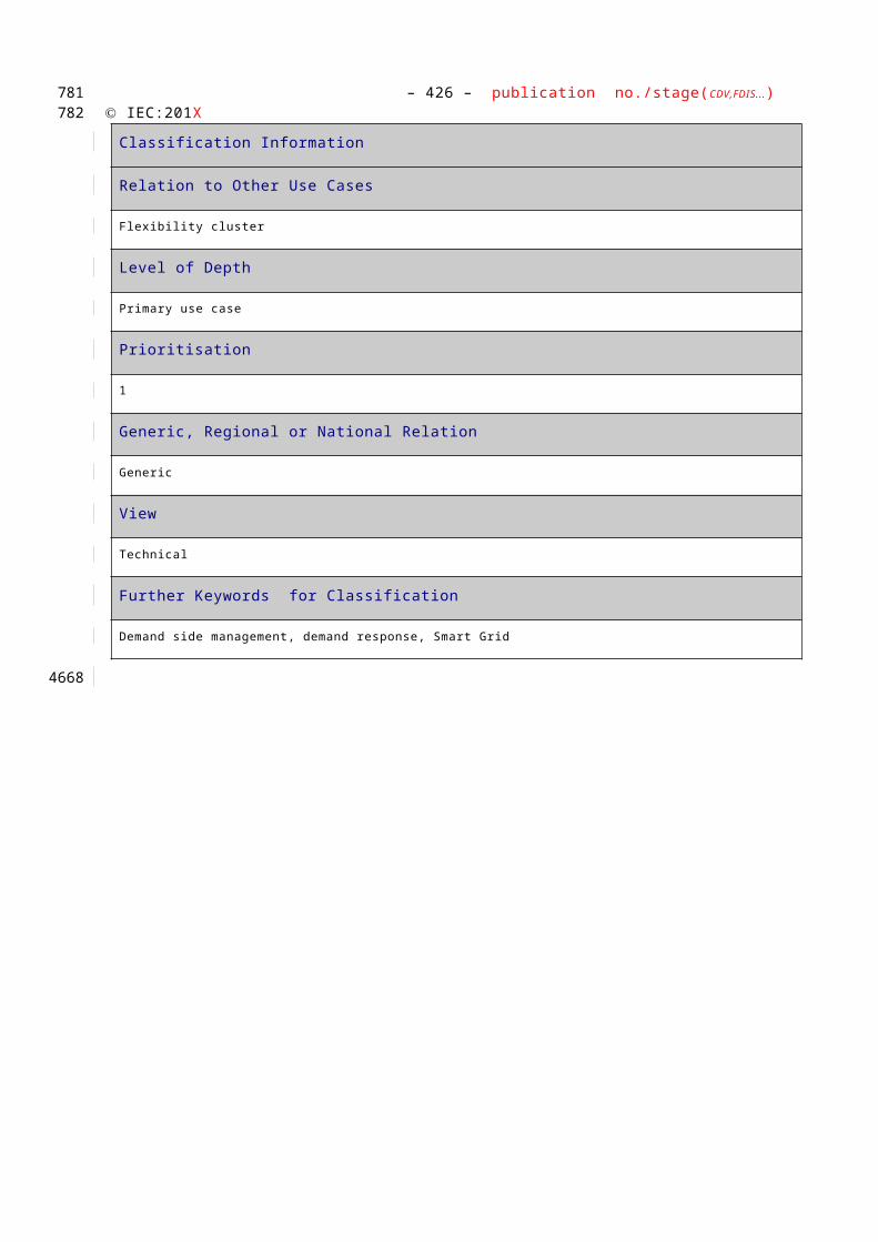
– 426 – publication no./stage(CDV,FDIS...) IEC:201X
HIGH LEVEL USE CASE (WGSP2140) Tariff synchronization
Description of the Use Case
Name of Use Case
Use Case Identification
ID Domain(s) Name of Use Case
WGSP 2140
Smart Grid Time synchronization
Version Management
Version Management
Changes / Version
Date NameAuthor(s) or Committee
Domain Expert
Area of Expertise / Domain / Role
Title Approval Status
draft, for comments, for voting, f inal
0.1 27/08/2012
Willem Strabbing - The European Smart Meter Industry Group (ESMIG)
Tim Sablon - The European Smart Meter Industry Group (ESMIG)
Various contributions from Smart Grid Coordination Group members (version history will be included in the next version).
Domain expert
Editor
Initial draft
Draft
0.5 12/11/2012
Tim Sablon - The European Smart Meter Industry Group (ESMIG)
Editor Initial draft
Draft
Scope and Objectives of Use Case
Scope and Objectives of Use Case
Related business case Time synchronization between the CEM and the Smart meter is a prerequisite for billing of the CEM’s response to flexible tariffs.
687688
44254426
4427
4428
4429
4430
4431
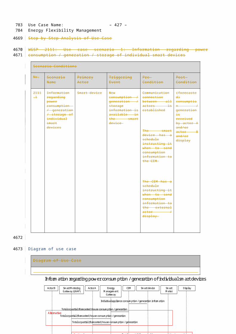
Use Case Name: – 427 –Energy Flexibility Management
Scope The scope of this use case is the communication between the CEM and "upstream"15 actors. The communication between CEM, the consumer and (in-home) smart devices is officially not in this scope of this report, but will be included in the Use Case description for the sake of clarity. Smart devices cover also smart appliances, generators and storage (see table with actors).
From an architectural point of view the Smart Grid Coordination Group introduced the "Smart Grid Connection Point" (SGCP) entity as an interface between Smart Grid actors (applications and/or organizations) and in-home/building systems or devices. The diagram below shows the SGCP in its environment.
Please note that the boxes in the diagram above are functional. The Smart Meter and CEM can be one or two separate physical boxes. The CEM can also be integrated in Smart in-home devices. The communication with the Grid market/applications can be through one or through separate infrastructures.
Objective The objective of this use case is to exchange information between the CEM and smart meter in order the keep the active tariff in the CEM and smart meter synchronized.
Narrative of Use Case
Narrative of Use Case
Short description – max 3 sentences
This use case describes how tariff synchronization between a CEM and a smart meter takes place
Complete description
15 Upstream in this context means towards actor A or B (see actor definitions)
689690
4432
4433
691

– 428 – publication no./stage(CDV,FDIS...) IEC:201X
Since the CEM can manage local consumption / generation based on flexible tariffs while the billing will take place based on information in the smart meter, both the smart meter and the CEM need to have the same tariff schedule and need to know when a new tariff applies. This can be achieved by:
Time synchronicity between the CEM and the smart meter;
The smart meter notifying the CEM when the active tariff changes.
WGSP 2112 describes how this tariff schedule (price information) is sent from an external actor to the CEM and to the smart meter.
WGSP-2141 describes how time synchronicity between CEM and Smart Meter is maintained.
The CEM may get time-stamped messages from the smart meter on regular intervals. Based on the time information in these messages, the CEM will keep its clock synchronized with the smart meter. The above process is not described in a separate use case since it works on top of existing information exchanges.
Next to the process described above, WGSP-2141 consists of two scenarios describing how time synchronization may also be achieved:
The CEM may request the time from the smart meter, based on which the CEM will synchronize its clock. Such a request may be sent on a regular basis (e.g. when there would be no other regular communication between smart meter and CEM) or it may be sent after the CEM has noticed that it may be out of synch (e.g. after an event like a power outage).
Based on time stamped messages from the CEM, the smart meter may notice the former is out of synch, after which the smart meter will send a synchronization parameters to the CEM, forcing it to synchronize.
This use case assumes that the smart meter has the correct time. A use case from the Smart Meters Coordination Group (INCO.02) describes how the time in the smart meter may be synchronized with the LNAP / NNAP / HES.
If the time difference between smart meter and CEM exceeds a certain level an alarm can be raised as described in in primary use case WGSP2142. In this case, a manual intervention will often be required since these larger variations from the time standard may indicate a faulty time clock which may need follow-up.
Another way to maintain tariff synchronicity if for the CEM and the Smart Meter to have the same tariff list, where the tariff list in the CEM contains the tariff identifier and the price, but does not contain a schedule indicating which tariff is applicable at which time. In this case the smart meter will send a notification to the CEM when the active tariff has changed. This notification identifies the active tariff. WGSP 2143 describes how the Smart Meter notifies the CEM when the active tariff changes..
General Remarks
General Remarks
692693
4434
4435

Use Case Name: – 429 –Energy Flexibility Management
Diagrams of Use Case
Diagram of Use Case
See detailed description os use cases
694695
4436
4437
4438

– 430 – publication no./stage(CDV,FDIS...) IEC:201X
Technical Details
Actors: People, Systems, Applications, Databases, the Power System, and Other Stakeholders
For the definition of this use case, the following architecture has been used as a basis.
Note that the actors in the above architecture are functional entities, which means that some of them may be part of the same physical device (e.g. CEM functionality may be part of a smart device, the smart meter might also encompass the smart metering gateway and CEM, etc…)
Actors
Grouping (Community) Group Description
Actor Name
see Actor List
Actor Type
see Actor List
Actor Description
see Actor List
Further information specific to this Use Case
Customer Energy Manager (CEM)
Internal The CEM is a logical function optimising energy consumption and or production based on signal s received from the grid, consumer’s settings and contracts, and devices minimum performance standards. The Customer Energy Manager collects messages sent to and received from connected devices; especially the in-home/building sector has to be mentioned. It can handle general or dedicated load
CEM Smart Device*
Simple external consumer
display
Actor AEnergy
management gateway (EMG)
Smart Metering gateway (LNAP )
Smart meter functionalityActor B
Energy Management / Providing Flexibility (M490)
M441 architecture
Market communication
* e.g. HBES device, smart appliances, storage, generator, domestic charger for EV, complex display
Smart Grid Connection
Point
Functional metering reference architecture according the SM-CG (TR50572)
696697
4439
44404441
4442
4443
4444
4445
444644474448
4449

Use Case Name: – 431 –Energy Flexibility Management
and generation management commands and then forwards these to the connected devices. It provides vice versa information towards the “grid / market”. Note that multiple loads/generation resources can be combined in the CEM to be mutually controlled.
When the CEM is integrated with communication functionalities it is called a Customer Energy Management System or CEMS.
Energy management gateway
Internal An access point (functional entity) sending and receiving smart grid related information and commands between actor A and the CEM, letting the CEM decide how to process the events. The communication is often achieved through an internet connection of through a wireless connection.
This gateway may also provide services including protocol conversion, device management, security and service capabilities.
Smart Metering gateway (LNAP)
Internal An access point (functional entity) that allows access to one or more metering end devices and, when equipped with an interface, to advanced display / home automation end devices connected to the local network.
A LNAP also may allow data exchange between different functional entities connected to the same LN. The LNAP may act simply as a router transferring messages between the metering end device and/or display/home automation devices and the Neighbourhood network of wide area network.
It may also provide services including protocol conversion, device management, security and service capabilities. Services may be provided as functions of the LNAP itself or provide proxy services on behalf of limited capability devices connected to the local network.
Smart meter Internal The metering end device is a combination of the following meter-related functions from the Smart Metering reference architecture:
Metrology functions including the conventional meter display (register or index) that are under legal metrological control. When under metrological control, these functions shall meet the essential requirements of the MID;
One or more additional functions not covered by the MID. These may also make use of the display;
Meter communication functions.
NNAP Internal The Neighbourhood Network Access Point is a functional entity that provides access to one or more LNAP’s, metering end devices, displays and home automation end devices connected to the neighbourhood network (NN). It may allow data exchange between different functional entities connected to the same NN.
698699

– 432 – publication no./stage(CDV,FDIS...) IEC:201X
Simple external consumer display
External
Dedicated display screen in connection with the smart meter/SGCP available to the customer to check power consumption, planned load reductions and load reductions historical. Other not dedicated means also exist to deliver consumption information to the customer, such as the personal computer, the mobile phone or the TV set.
Smart device External
A smart device may be an appliance, generator or storage device (Local storage devices include direct and functional electricity storages such as electrochemical batteries, heat pumps and micro CHP such as fuel cells with heat buffers, air conditioning and cooling devices with thermal inertia, etc…). The smart device can receive data directly from the grid, though an interface with the CEM and can react to commands and signal s from the grid in an intelligent way.
Since the smart device is outside the scope of the SGCG, it must be seen as an external actor
Smart appliance (white goods)
External
An example of a smart device is a smart white goods appliance which is an appliance that has the capability to act in response to a signal from the grid and thereby optimize its behaviour towards the energy supply network. The signal can be received from a utility or a third party energy service provider directly or via a home energy management system,
The signal can be information like the cost of energy or the amount of available renewable energy, or it can be a Demand Respond signal (delay load signal or other related information) that the appliance must receive, interpret and react upon based on pre-set or active consumer input. The smart appliance is not guaranteed to respond, but will do so based on its status and user settings in order to ensure the expected performance.
The consumer has the ultimate control of the appliance and can override any specific mode (e.g. override a delay to allow immediate operation, limit delays to no more than a certain number of hours, or maintain a set room temperature).
Any appliance operation settings or modes shall be easy for an average, non-technical consumer to activate or implement.
Actor A External
External actor (Smart Grid Market Role) interacting with the system functions and components in the home or home automation network through the energy management communication channel.. Examples of such market roles are the Energy Provider, the Energy Services Provider, the aggregator, etc…
HES Internal Responsible for acquiring the reads from meters and/or from data concentrators
Delivers the raw meter reads to MDM
Repeats the reading for any missing reads
Is the short-term interim data storage (1-3 months) for
700701

Use Case Name: – 433 –Energy Flexibility Management
meter reads
Pushes the event information upwards to MDM
Supports the specific protocols of the concentrators and meters
Contains some topology information and aggregation functionality for plug & play solutions
MDM Internal Is the single meter data repository for all metering data
Is the long-term storage for the metering data
Ensures the data quality by VEE for the higher level business processes
Connects all head-end systems
Is the connection point for other systems to reach the smart meters i.e. a gateway to HES and back
Delivers the meter reads to other business systems for further usage
Acts as the critical security firewall between business and operational systems and the advanced metering infrastructure.
Contains some topology information and aggregation functionality
Actor B External
External actor (Smart Grid Market Role) interacting with the system functions and components in the home or home automation network through the metering communication channel. This actor is responsible for collecting metering data. Examples of such market roles are the DSO, metering company, etc.
Preconditions, Assumptions, Post condition, Events
Use Case Conditions
Actor/System/Information/Contract Triggering Event Pre-conditions Assumption
References / Issues
References
702703
4450
4451
4452
4453

– 434 – publication no./stage(CDV,FDIS...) IEC:201X
No. References Type Reference Status Impact on Use Case
Originator / Organisation
Link
1. Use case SMCG use case: INCO.02 – Time synchronization
Draft Smart Meters Coordination Group
Further Information to the Use Case for Classification / Mapping
Classification Information
Relation to Other Use Cases
Flexibility cluster
Level of Depth
Primary use case
Prioritisation
1
Generic, Regional or National Relation
Generic
View
Technical
Further Keywords for Classification
Demand side management, demand response, Smart Grid
Step by Step Analysis of Use Case
WGSP 2141 – scenario 1: CEM requests time
Scenario Conditions
No. Scenario Name
Primary Actor Triggering Event Pre-Condition Post-Condition
2141
CEM requests time
CEM CEM is triggered to request time from smart meter
Communication between all actors can be established
There is a rule base laying down the rules based on which the CEM will be triggered to
CEM received the correct time and has synchronized its clock
704705
4454
4455
4456
4457

Use Case Name: – 435 –Energy Flexibility Management
request the time
Diagram of use case
Diagram of Use Case
706707
4458
4459
4460

– 436 – publication no./stage(CDV,FDIS...) IEC:201X
Steps – Normal
Scenario
Scenario Name
Provide flexibility:
Step No.
Event Name of Process/ Activity
Description of Process/ Activity
Zones / Domains
Information Producer (Actor)
Information Receiver (Actor)
Information
Requirements , R-ID Exchang
ed
1 CEM is triggered to request time from smart meter
CEM requests time from smart meter CEM
Energy manegement gateway
Time request
2 Energy management gateway receives time request
Energy management gateway forwards request to smart metering gateway
Energy management gateway
Smart metering gateway
Time request
3 Smart metering gateway receives time request
Smart metering gateway forwards request to smart meter
Smart metering gateway
Smart meter
Time request
4Smart meter receives time request
Smart Meter sends synchronization parameters to the smart metering gateway
Smart meter
Smart metering gateway
Synchronization parameters
5Smart metering gateway receives synchronization parameters
Smart metering gateway sends the synchronization parameters to the energy management gateway
Smart metering gateway
Energy management gateway
Synchronization parameters
6 Energy management gateway receives synchronization parameters
Energy management gateway sends the synchronization parameters to the CEM.
Energy management gateway
CEM
Synchronization parameters
WGSP 2141 – scenario 2: Smart meter sends time
Scenario Conditions
No. Scenario Name
Primary Actor Triggering Event Pre-Condition Post-Condition
214 Smart meter Smart meter Smart meter Communication CEM received
708709
4461
4462
4463

Use Case Name: – 437 –Energy Flexibility Management
1 sends time notices that CEM is out of synch
between all actors can be established
There is a rule base laying down the rules based on which the Smart meter will be triggered to send the time
the correct time and has synchronized its clock
710711
4464
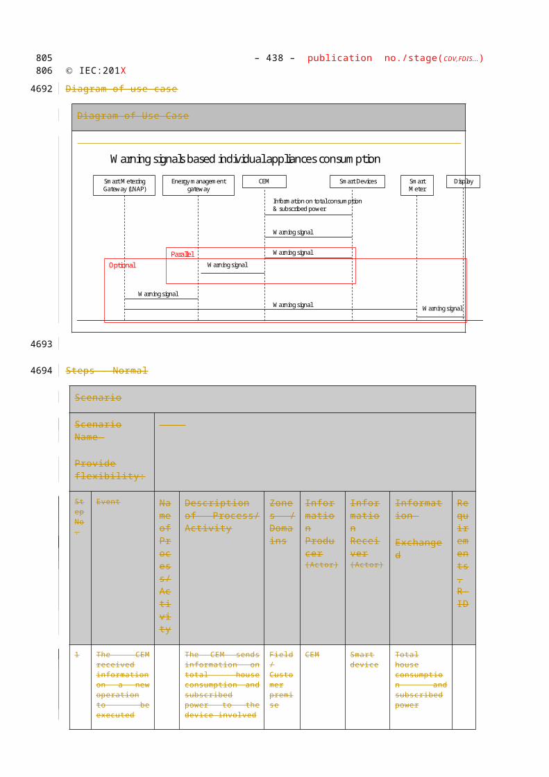
– 438 – publication no./stage(CDV,FDIS...) IEC:201X
Diagram of use case
Diagram of Use Case
Steps – Normal
Scenario
Scenario Name
Provide flexibility:
Step No.
Event Name of Process/ Activity
Description of Process/ Activity
Zones / Domains
Information Producer (Actor)
Information Receiver (Actor)
Information
Requirements , R-ID Exchang
ed
1 Smart meter notices that CEM is out of synch
Smart meter sends synchronization parameters
Smart Meter
Smart metering gateway
Synchronization parameters
2 Smart metering management gateway receives information
Smart metering gateway forwards information to energy management gateway
Smart metering gateway
Energy management gateway
Synchronization parameters
3 Energy management gateway receives information
Energy management gateway forwards synchronization parameters to CEM
Energy management gateway
CEM
Synchronization parameters
WGSP 2142: CEM sends out-of-synch alarm
Scenario Conditions
No. Scenario Primary Actor Triggering Event Pre-Condition Post-
712713
4465
4466
4467
4468
4469

Use Case Name: – 439 –Energy Flexibility Management
Name Condition
2142
CEM sends out of synch alarm
CEM The CEM notices a time difference exceeding the alarm level
Communication between all actors can be established
There is a rule base laying down thresholds identifying what to do depending on the time difference that has been identified
The alarm has been received by an external actor
Diagram of use case
Diagram of Use Case
Steps – Normal
Scenario
Scenario Name
Provide flexibility:
Step No.
Event Name of Process/ Activity
Description of Process/ Activity
Zones / Domains
Information Producer (Actor)
Information Receiver (Actor)
Information
Requirements , R-ID Exchang
ed
1 The CEM notices a time difference exceeding the alarm level
CEM sends alarm to energy management gateway
CEM
Energy management gateway
Alarm (large time difference)
2a Energy management gateway receives alarm
Energy management gateway forwards alarm to actor A
Energy management gateway
Actor A Alarm (large time differenc
Actor A CEMS
CEM sends out-of-synch alarm
Energy Management Gateway
Smart MeteringGateway
Smart Meter
Alarm (time out of synch)
Alarm (time out of synch)
Actor A
Alarm (time out of synch)
Alarm (time out of synch)
Alternative
714715
4470
4471
4472

– 440 – publication no./stage(CDV,FDIS...) IEC:201X
e)
2b Energy management gateway receives alarm
Energy management gateway forwards alarm to smart metering gateway
Energy management gateway
Smart metering gateway
Alarm (large time difference)
3Smart metering gateway receives alarm
Smart metering gateway forwards alarm to actor B
Smart metering gateway
Actor B
Alarm (large time difference)
WGSP 2143: Smart meter notifies active tariff change
Scenario Conditions
No. Scenario Name
Primary Actor Triggering Event Pre-Condition Post-Condition
2143
Smart meter notifies active tariff change
Smart Meter The smart meter changed the active tariff
Communication between all actors can be established
The CEM is informed of the new active tariff
716717
4473
4474
4475

Use Case Name: – 441 –Energy Flexibility Management
Diagram of use case
Diagram of Use Case
Steps – Normal
Scenario
Scenario Name
Provide flexibility:
Step No.
Event Name of Process/ Activity
Description of Process/ Activity
Zones / Domains
Information Producer (Actor)
Information Receiver (Actor)
Information
Requirements , R-ID Exchang
ed
1 The smart meter changed the active tariff
Smart meter sends an active tariff notification to the smart metering gateway
Smart Meter
Smart metering gateway
Active tariff notification
2Smart metering gateway receives notification
Smart metering gateway sends notification to energy management gateway
Smart metering gateway
Energy management gateway
Active tariff notification
Energy management gateway receives notification
Energy management gateway sends notification to CEM
Energy management gateway
CEM
Active tariff notification
Steps – Alternative, Error Management, and/or Maintenance/Backup Scenario
Scenario
Actor A CEMS
Smart meter sends time
Energy Management Gateway
Smart MeteringGateway
Smart Meter
Active tariffnotification
Active tariffnotification
Active tariffnotification
718719
4476
4477
4478
4479
4480
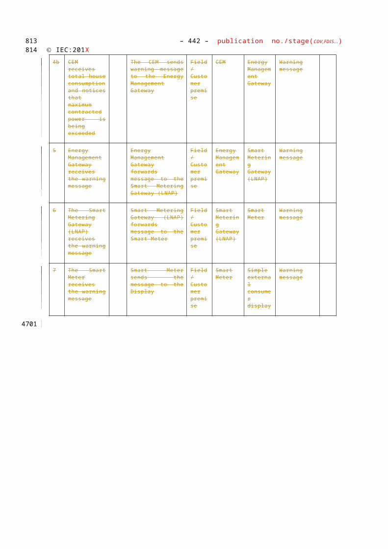
– 442 – publication no./stage(CDV,FDIS...) IEC:201X
Scenario Name :
Provide flexibility:
Step No.
Event Name of Process/Activity
Description of Process /Activity
Service
Information Producer
Information Receiver
Information
Requirements, R-ID
Exchanged
720721
4481
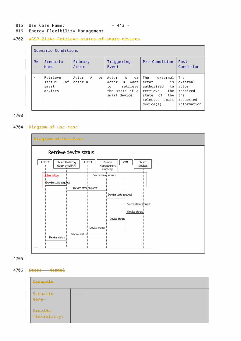
Use Case Name: – 443 –Energy Flexibility Management
Information Exchanged
Information Exchanged
Name of Information Exchanged Description of Information Exchanged
Requirements to information data R-ID
Time request
Synchronization parameters
The COSEM Clock Object provides the means to set and synchronize the clock.
Parameters may be:
Absolute time
Time relative to tariff schedule
Alarm (large time difference)
Active tariff notification
Common Terms and Definitions
Common Terms and Definitions
Term Definition
Notes and open issues
Notes and open issues
Nr Note
1. Where relevant all primary use case (scenarios) may be split up according to external actors
2. Next step: define additonal use cases using the top down method, considering the functional architecture as a black box and identifying which messages would go in / come out
722723
4482
4483
4484
4485
4486
4487

– 444 – publication no./stage(CDV,FDIS...) IEC:201X
Management & Monitoring
Simple Smart Device management
Set On / Off / Start / Stop / Pause / Resume / Abort / Dim
Set Timer
Set Temperature
On/off: actuatorSwitchData
Dim: actuatorLevelData
Use case description with Message Sequence Charts
Data requirements within Use Case:
CEM Smart Device Program Status request / notification
Off
Ready / Idle
Flexible start programmed / waiting for start
Running
Pause
Operation on Hold / Waiting Mode
Finished
Error status
On/off: actuatorSwitchData
Dim: actuatorLevelData
Use case description with Message Sequence Charts
Data requirements within Use Case:
CEM Smart Device Information request / Alerts / Notifications
724725
4488
4489
4490
4491
4492
4493
4494
4495
4496
4497
4498
4499
4500
4501
4502
4503
4504
4505
4506
4507
4508
4509
4510
4511
4512
4513
4514
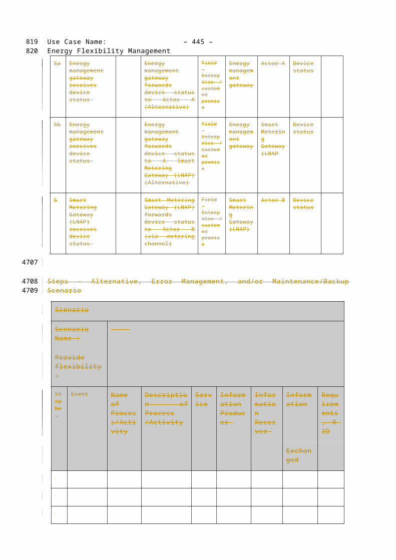
Use Case Name: – 445 –Energy Flexibility Management
Device capabilities
Time info
Temperature
Door / contact status info
Error message
Use case description with Message Sequence Charts
Data requirements within Use Case:
SG CP CEM Information request / Alerts / Notifications
Warning signals
Use case description with Message Sequence Charts
Data requirements within Use Case:
Registration
Use case description with Message Sequence Charts
Data requirements within Use Case:
Deregistration
Use case description with Message Sequence Charts
Data requirements within Use Case:
726727
4515
4516
4517
4518
4519
4520
4521
4522
4523
4524
4525
4526
4527
4528
4529
4530
4531
4532
4533
4534
4535
4536
4537
4538
4539
4540
4541

– 446 – publication no./stage(CDV,FDIS...) IEC:201X
728729
4542
4543


![OASIS Specification Template · Web view[ISO/IEC Part 2] ISO/IEC Directives, Part 2, Rules for the structure and drafting of International Standards (2011, 6th edition) [OASIS]](https://static.fdocuments.net/doc/165x107/5b38cfb77f8b9abd438daf8b/oasis-specification-template-web-viewisoiec-part-2-isoiec-directives-part.jpg)