IEA Solar Heating and Cooling Programme · The Solar Heating and Cooling Programme was one of the...
209
Transcript of IEA Solar Heating and Cooling Programme · The Solar Heating and Cooling Programme was one of the...

IEA Solar Heating and Cooling Programme
The International Energy Agency (IEA) was established in 1974 as an autonomous agency within the framework ofthe Organization for Economic Cooperation and Development (OECD) to carry out a comprehensive program of energycooperation among its 24 member countries and the Commission of the European Communities.
An important part of the Agency's program involves collaboration in the research, development and demonstration ofnew energy technologies to reduce excessive reliance on imported oil, increase long-term energy security and reducegreenhouse gas emissions. The IEA's R&D activities are headed by the Committee on Energy Research andTechnology (CERT) and supported by a small Secretariat staff, headquartered in Paris. In addition, three WorkingParties are charged with monitoring the various collaborative energy agreements, identifying new areas for cooperationand advising the CERT on policy matters.
Collaborative programs in the various energy technology areas are conducted under Implementing Agreements, whichare signed by contracting parties (government agencies or entities designated by them). There are currently 41Implementing Agreements covering fossil fuel technologies, renewable energy technologies, efficient energy end-usetechnologies, fusion technology and energy technology information centers.
The Solar Heating and Cooling Programme was one of the first IEA Implementing Agreements to be established. Since1977, its 21 members have been collaborating to advance active solar, passive solar and photovoltaic technologies andtheir application in buildings.
Australia Finland Netherlands TurkeyAustria France New Zealand United KingdomBelgium Germany Norway United StatesCanada Greece SpainDenmark Italy SwedenEuropean Commission Japan Switzerland
A total of 22 Tasks have been initiated, 17 of which have been completed. Each Task is managed by an OperatingAgent from one of the participating countries. Overall control of the program rests with an Executive Committeecomprised of one representative from each contracting party to the Implementing Agreement. In addition, a numberof special ad hoc activities--working groups, conferences and workshops--have been organized.
The Tasks of the IEA Solar Heating and Cooling Programme, both completed and current, are as follows:
Completed Tasks:
Task 1 Investigation of the Performance of Solar Heating and Cooling SystemsTask 2 Coordination of Solar Heating and Cooling R&DTask 3 Performance Testing of Solar CollectorsTask 4 Development of an Insolation Handbook and Instrument PackageTask 5 Use of Existing Meteorological Information for Solar Energy ApplicationTask 6 Performance of Solar Systems Using Evacuated CollectorsTask 7 Central Solar Heating Plants with Seasonal StorageTask 8 Passive and Hybrid Solar Low Energy BuildingsTask 9 Solar Radiation and Pyranometry StudiesTask 10 Solar Materials R&DTask 11 Passive and Hybrid Solar Commercial BuildingsTask 12 Building Energy Analysis and Design Tools for Solar ApplicationsTask 13 Advance Solar Low Energy BuildingsTask 14 Advance Active Solar Energy SystemsTask 16 Photovoltaics in BuildingsTask 17 Measuring and Modeling Spectral RadiationTask 20 Solar Energy in Building Renovation
Current Tasks and Working Groups
Task 18 Advanced Glazing Materials for Solar ApplicationsTask 19 Solar Air SystemsTask 21 Daylight in BuildingsTask 22 Solar Building Energy Analysis ToolsTask 23 Sustainable Solar Buildings: The Optimization of Solar Energy Use in Larger Buildings (Project
Definition Phase)Working Group Materials for Solar Thermal Collectors
Task reports and ordering information can be found in the IEA Solar Heating and Cooling Programme publications list.For additional information contact the SHC Executive Secretary, Pamela Murphy Kunz, Morse Associates Inc., 1808Corcoran Street, NW, Washington, DC 20009, USA, Telephone : +1/202/483-2393, Fax: +1/2021265-2248, E-mail:[email protected].

Report #T.14.DHW.1
Advanced Solar Domestic Hot
Water Systems
Editor - William Duff (United States)
October 1996
Additional Copies may be ordered from:
Professor William DuffSolar Energy Applications LaboratoryColorado State UniversityDepartment of Mechanical EngineeringFort Collins, Colorado 80523
Distribution Category: Unrestricted

TABLE OF CONTENTS
Chapter Page
LIST OF FIGURES .......................................................................................................
LIST OF TABLES .................................................................................................... viii
1. EXECUTIVE SUMMARY ......................................................................................... 1-1
1.1. Collector and Load ......................................................................................... 1-11.2. Solar Storage, Heat Exchanger, and Auxiliary ............................................... 1-21.3. Pump and Controller ...................................................................................... 1-31.4. Piping .............................................................................................................. 1-41.5. Other Low-Flow Considerations .................................................................... 1-51.6. Dream Systems ................................................................................................ 1-5
2. INTRODUCTION ....................................................................................................... 2-1
3. JUSTIFICATION FOR LOW FLOW ......................................................................... 3-1
3.1. Introduction .................................................................................................... 3-13.2. Low-Flow Cost Impact .................................................................................. 3-13.3. Low-Flow Performance Impact ...................................................................... 3-23.4. Low Flow, Tank Stratification, and Performance .......................................... 3-23.5. System Design Considerations ...................................................................... 3-3
4. COMPONENT REPORT: COLLECTORS, ABSORBERS, AND LOADS .......... 4-1
4.1. Absorber/Collector ......................................................................................... 4-14.1.1. Introduction ......................................................................................... 4-14.1.2. Design Guidelines ............................................................................... 4-14.1.3. Test Results ......................................................................................... 4-24.1.4. Insulation ............................................................................................. 4-34.1.5. Conclusions ......................................................................................... 4-3
4.2. Load Influence ................................................................................................ 4-34.2.1. Introduction ......................................................................................... 4-34.2.2. Load Profiles ...................................................................................... 4-44.2.3. Rationale ............................................................................................. 4-44.2.4. Results .................................................................................................. 4-44.2.5. Conclusions ......................................................................................... 4-4
i
5. COMPONENT REPORT: HEAT STORAGES, HEAT EXCHANGERS,6.AND AUXILIARIES .................................................................................................. 5-1
5.1. Introduction .................................................................................................... 5-15.2. Market and Regulatory Issues in Participating Countries ............................ 5-1
5.2.1. Canada ................................................................................................ 5-15.2.2. Denmark .............................................................................................. 5-25.2.3. The Netherlands .................................................................................. 5-35.2.4. Spain .................................................................................................... 5-45.2.5. Switzerland ......................................................................................... 5-55.2.6. United States ....................................................................................... 5-5
5.3. Thermal Performance of Low-Flow Systems with DifferentlyDesigned Heat Storages .................................................................................. 5-65.3.1. Heat Storages With Built-In Auxiliary Energy Supply ................... 5-65.3.2. Heat Storages Without Built-In Auxiliary Energy Supply .............. 5-8
5.4. Auxiliary Energy Supply System .................................................................... 5-95.5. Conclusions .................................................................................................. 5-11
7. COMPONENT REPORT: PUMPS AND CONTROLLERS ................................... 6-1
6.1. Introduction .................................................................................................... 6-16.1.1. Overview .............................................................................................. 6-16.1.2. Centrifugal Pumps ................................................................................ 6-16.1.3. Positive Displacement Pumps ............................................................. 6-3
6.2. Comparison of Different Concepts .................................................................. 6-46.3. Design Criteria for Low-Flow Pumps and Controls ...................................... 6-4
6.3.1. Pumps .................................................................................................. 6-46.3.2. Controls ................................................................................................ 6-4
6.4. Development of a New Low-Flow Pump ...................................................... 6-56.4.1. Project .................................................................................................. 6-56.4.2. Purpose .............................................................................................. 6-56.4.3. Description of Work ........................................................................... 6-56.4.4. Control ................................................................................................ 6-7
6.5. Future Developments ....................................................................................... 6-76.6. Conclusions .................................................................................................... 6-8
6.6.1. Common Conclusions ......................................................................... 6-86.6.2. Specific Conclusions (Canadian Pump) ............................................. 6-86.6.3. Direct Comparison with Other Pump Designs ................................... 6-8
8. COMPONENT REPORT: PIPING ........................................................................... 7-1
7.1. Introduction .................................................................................................... 7-17.2. Comparison of Flexible Piping for Low-Flow DHW Systems
to Fixed Piping in Traditional DHW Systems ............................................... 7-2
7.3. Design of Different Concepts ......................................................................... 7-37.3.1. Fixed Tubing ....................................................................................... 7-3
ii

7.3.2. Flexible Tubing Swiss Flextube® ........................................................ 7-47.3.3. Flexible Tubing Canadian Life-Line® ....................................................................... 7-5
7.4. Pressure Drop of Different Concepts ............................................................. 7-67.4.1. Discussion of Results ......................................................................... 7-6
7.5. Heat Loss ....................................................................................................... 7-107.5.1. Results of Heat Loss Measurements ............................................... 7-127.5.2. Analysis of Heat Losses in Flexible Piping Bundles ..................... 7-12
7.6. Materials and Requirements ......................................................................... 7-137.6.1. Results of Aging Tests, Experiences in the Field .......................... 7-14
7.7. Conclusion .................................................................................................... 7-14
8. LOW-/HIGH-FLOW TEST ......................................................................................... 8-1
8.1. Introduction .................................................................................................... 8-18.2. Description of the Tested Systems .................................................................. 8-18.3. Test Procedure ................................................................................................ 8-38.4. Test Results .................................................................................................... 8-58.5. Conclusions .................................................................................................... 8-78.6. Final Remarks .................................................................................................. 8-8
9. COUNTRY INFORMATION AND STATISTICS .................................................... 9-1
9.1. Introduction .................................................................................................... 9-19.2. Tables .............................................................................................................. 9-1
10. BASE CASE AND DREAM SYSTEM .................................................................. 10-1
10.1. Introduction .................................................................................................. 10-110.2. System Diagrams ......................................................................................... 10-110.3. Tables ........................................................................................................... 10-1
11. CONCLUSIONS AND FINAL REMARKS ........................................................... 11-1
12. ACKNOWLEDGEMENTS AND CONTACTS ...................................................... 12-1
12.1. Acknowledgements ...................................................................................... 12-1
12.2. Contacts ......................................................................................................... 12-2
APPENDIX A. BASE CASE AND DREAM SYSTEM COUNTRYCONTRIBUTIONS ......................................................................... A-1
A1. CANADA ........................................................................................... A-3A2. DENMARK ...................................................................................... A-13
A3. GERMANY ...................................................................................... A-23
A4. THE NETHERLANDS .................................................................... A-43
A5. SWITZERLAND ............................................................................. A-53A6. UNITED STATES ........................................................................... A-63
iii

APPENDIX B. COUNTRY REPORTS .................................................................... B-1B 1. CANADA ....................................................................... B-3B2. DENMARK ................................................................... B-13B3. GERMANY ................................................................... B-19B4. THE NETHERLANDS ..................................................... B-23B5. SWITZERLAND ............................................................ B-27B6. UNITED STATES .......................................................... B-29
REFERENCES .............................................................................................................. 1

LIST OF FIGURES
Figure Page
1-1 Canadian Dream System Diagram ............................................................................. 1-6
1-2 Danish Dream System Diagram .................................................................................. 1-6
1-3 German Dream System Diagram ............................................................................... 1-7
1-4 The Netherlands Dream System Diagram .................................................................. 1-7
1-5 Swiss Dream System SOLKIT ® .................................................................................. 1-8
1-6 United States Dream System for Freezing Climates .................................................. 1-8
5-1 Schematic Illustration of Four Low-Flow Solar Heating Systems Investigatedin Denmark with Differently Designed Heat Storages ............................................. 5-7
5-2 Schematic Illustration of the Five Investigated Heat Storages .............................. 5-10
6-1 Grundfos UPS 25-40 Pump Performance (Source: Grundfos) ................................. 6-2
6-2 Bosch Impeller Pump Performance (Source: TNO, NL) .......................................... 6-2
6-3 PTFE Diaphragm KNF ND 1.100 KT Pump Performance (Source:KNF data sheets via SPF/ITR , Rapperswil) ............................................................... 6-3
6-4 Canadian Nanopump First Prototype Performance (Source:Negentropy Inc. in-house tests) .................................................................................. 6-6
7-1 Scheme of the Traditional and Low-Flow Systems .................................................. 7-2
7-2 Cross Section of the Typical Fixed Tubing ............................................................... 7-3
7-3 Cross Section of the Swiss Flextube® ...................................................................... 7-4
7-4 A Diagram of the Fittings Connecting the Collector / Flextube®and the Storage / Flextube ® .................................................................................................................................. 7-5
7-5 Cross Section of the Canadian Life-Line® ............................................................... 7-5
7-6 Comparison of the Pressure Drop for Different TubingDesigns and Flow Rates ............................................................................................. 7-7

7-7 Typical Operation of a Low-Flow and a Traditional Systemon a Sunny Day ....................................................................................................... 7-11
8-1 Scheme of the Tested DHW Pre-heat Systems ......................................................... 8-2
8-2 Weather Data for the Three-Day Test Period ........................................................... 8-4
10-1 Canadian Base Case System Diagram .................................................................... 10-2
10-2 Canadian Dream System Diagram ........................................................................... 10-2
10-3 Danish Base Case System Diagram ......................................................................... 10-3
10-4 Danish Dream System Diagram ................................................................................ 10-3
10-5 German Base Case System Diagram ....................................................................... 10-4
10-6 German Dream System Diagram ............................................................................. 10-4
10-7 The Netherlands Base Case System Diagram ......................................................... 10-5
10-8 The Netherlands Dream System Diagram ................................................................ 10-5
10-9 Common Domestic Hot Water System in Switzerland ........................................... 10-6
10-10 Swiss Dream System SOLKIT ® 10-6
10-11 United States Base Case System for Freezing Climates ........................................ 10-7
10-12 United States Dream System for Freezing Climates ............................................... 10-7
A1-1 Canadian Base Case System Diagram ....................................................................... A-3
A1-2 Canadian Dream System Diagram .............................................................................. A-6
A2-1 Danish Base Case System Diagram ......................................................................... A-13
A2-2 Danish Dream System Diagram ................................................................................ A-16
A3-1 German Base Case System Diagram ....................................................................... A-23
A3-2 German Dream System Diagram .............................................................................. A-28
A3-3 Storage-Installation-Kit and Bracket ......................................................................... A-28
A3-4 Absorber Flow Design .............................................................................................. A-29
vi
A3-5 Flextube® System .................................................................................................... A-30
A4-1 The Netherlands Base Case System Diagram ........................................................ A-43
A4-2 Base Case System Collector Efficiency Curve ........................................................ A-44
A4-3 The Netherlands Dream System Diagram ............................................................... A-46
A4-4 Dream System Collector Efficiency Curve ............................................................. A-47
A5-1 Common Domestic Hot Water System in Switzerland .......................................... A-53
A5-2 Swiss Dream System SOLKIT ® A-56
A6-1 United States Base Case System for Freezing Climates ........................................ A-63
A6-2 United States Dream System for Freezing Climates ............................................... A-66
B1-1 Hot Water Usage for a Typical Canadian Household (ℓ/hr) . B-4
B1-2 Average Daily Radiation on Surface at Tilt = Latitude for Various lEAMember Countries (MJ/m2/day) .................................................................................. B-5
B1-3 Comparison of Total Solar Radiation at Tilt = Latitude for VariousCanadian Locations (MJ/m2/day) ............................................................................... B-6
B1-4 Solar Resource for Toronto at Tilt = Latitude (kWh/m2/day) ................................... B-7
B1-5 Projected Electricity and SDHW Costs ...................................................................... B-9
B1-6 Projected SDHW Installations in Canada by Province in Year 2000 ................... B -10
B2-1 Number of Installed Solar Heating Systems in Denmark ...................................... B-17
B3-1 Climatic Map for Germany ...................................................................................... B-22
vii

LIST OF TABLES
Table Page
1-1 Costs, Performance, and Comparisons ...................................................................... 1-9
7-1 Materials .................................................................................................................. 7-13
8-1 Main Characteristics of the Tested DHW Pre-Heat Systems ................................... 8-3
8-2 Hot Water Consumption During the Test Period ...................................................... 8-5
8-3 Tapped Energy Quantities for the Helix System, Both for Highand Low Flow .............................................................................................................. 8-6
8-4 Tapped Energy Quantities for the Mantle System, Both for Highand Low Flow .............................................................................................................. 8-6
9-1 Climate ....................................................................................................................... 9-2
9-2 Infrastructure and Demographics ................................................................................ 9-2
9-3 Statistics ....................................................................................................................... 9-3
9-4 Manufacturers' Workshops Held in Conjunction with Task Meetings ..................... 9-4
10-1 Base Case Description ............................................................................................. 10-8
10-2 Dream System Description .................................................................................... 10-10
10-3 Costs, Performance, and Comparisons .................................................................. 10-12
A1-1 Thermal Performance of Canadian Base Case System .......................................... A-10
A1-2 Thermal Performance of Canadian Dream System ................................................. A-12
A3-1 Radiation and Annual Performance for the German Base CaseSystem ....................................................................................................................... A-36
A3-2 Annual Values for Friedrichshafen, the Location With the Highest AnnualSolar Insolation in Germany (4523 MJ/m2yr; 1256.4 kWh/m2yr) . A-36
A3-3 Radiation and Annual Performance for the German Dream System ..................... A-38
viii

A 3-4 Annual Values for Friedrichshafen, the Location With the Highest AnnualSolar Insolation in Germany (4523 MJ/m2yr; 1256.4 kWh/m2yr) .......................... A-39
A 3-5 Cost Performance Comparison ................................................................................ A-40
B 1-1 Canadian Water Heater Market Data (# in 000's) .................................................... B-3
B 1-2 Monthly Average Horizontal Radiation and Daytime High Temperaturefor Selected Canadian Cities ...................................................................................... B-8
B 1-3 Typical Canadian Energy Prices ($94/output GJ) ...................................................... B-9
B 2-1 Weather Data From the Danish Test Reference Year ............................................. B-14
B 3-1 SDHW - Sales Development .................................................................................... B-19
B 3-2 Climatic Data for Germany ...................................................................................... B-21
B 5-1 Switzerland Weather Data ...................................................................................... B-28
B 6-1 United States Weather Data .................................................................................... B-29

Task 14 - Advanced Active Solar Systems
Task 14 was initiated to advance the state-of-the-art in active solar energy systems. Manyfeatures developed during the few years before the start of the Task, when used alone or incombination, had the potential to significantly improve the performance of these systems. It wasthe objective of Task 14 to analyze, design, evaluate and, in some cases, construct and monitora number of different systems incorporating one or more of these features.
The work of the Task was divided into three Working Groups, based on the type of systemsstudied, and one Sub Task dealing with dynamic testing. The goal of the Working Groups wasto facilitate interaction between participants with similar projects. Participants were able toidentify and address issues of common interest, exchange knowledge and experience andcoordinate collaborative activities.
Domestic Hot Water (DHW) Systems - Working Group
The focus of this Working Group was the development of advanced DHW systems using the"low flow" concept. Participating countries contributed expertise related to different systemcomponents. The collaborative work in the Task brought this expertise together to allowparticipants from each country to design systems which show a significant cost/performanceimprovement (as high as 48%) over systems on the market in their respective countries when theTask began.
Air Systems - Working Group
Task work concentrated on further development of a commercially available concept for thepreheating of ventilation air in industrial and commercial buildings. This concept is a speciallydesigned cladding system to capture the air heated by solar radiation on the south wall of abuilding. Four projects, two in Canada, one in the USA and one in Germany, were constructedusing a perforated version of the wall. The German project adapted the concept to preheatcombustion air for a district heating plant. The practical work of these projects wascomplemented by theoretical work conducted at the University of Waterloo in Canada and theNational Renewable Energy Laboratory (NREL) in the United States. Task work demonstratedthat the cost/performance of the perforated wall is over 35% greater than earlier versions of thedesign.
Large Systems - Working Group
The Task also examined large scale heating systems involving temperatures under 200°C. Fivelarge systems were studied. They were all very different but each represented importantapplications of active solar systems. District heating, the subject of the Swedish project, can beused in most IEA member countries to provide space and water heating for communities. The

German project also involved district heating but with no storage. A tulip bulb drying installationin The Netherlands explored the staggered charging and discharging of long term storage, astrategy which may fmd many uses, especially in agricultural applications. Solar desalination,the subject of the Spanish project, has wide application in water starved areas of the world andcould represent a major export opportunity for IEA countries. Industrial process heat wasrepresented by a project in Switzerland. Since virtually all large systems are custom designed,cost/performance improvements for this Group was not a meaningful measure of achievement.Documentation of lessons learned is the most important product of the work.
Dynamic System Testing Sub Task
The work of this Sub Task within Task 14 provided a continuation of work completed earlier bythe IEA Dynamic Systems Testing Group. That Group established that dynamic fitting was asuitable tool in processing laboratory tests and in-situ monitoring of solar domestic hot watersystems. The objective of the new sub-task in Task 14 is the continued development andevaluation of dynamic testing of solar energy systems, subsystems and components for predictionof long term system performance from short term tests.
Task 14 activities began in 1989 and were completed in 1995.
The following countries participated in this Task:
Canada The Netherlands SwitzerlandDenmark Spain United StatesGermany Sweden
xi

1. EXECUTIVE SUMMARY
The Task 14 Advanced Solar DHW Working Group set a goal of a greater than 15percent increase in the cost and performance of solar DHW systems over current practice. Thisgoal is interpreted as achieving designs that have an initial cost to annual energy delivered ratioimprovement (dollars/GJ) greater than 15 percent.
Actual cost performance gains ranged from 20-48 percent. These gains were a result ofmultiple improvements in heat exchangers, storage design, modularization, absorbers and piping.
Because regulations and practices regarding the design and construction of solar DHWsystems differed markedly from country to country, it was not possible to propose one universalTask 14 system. Instead, each country developed its own individual "Dream System." In orderto measure how well the goal was achieved, one of the most commonly available systems beingsold in each country at the time the Task began was selected as a comparative "Base Case."
Despite this lack of commonality, most specific system design features and componentscould still be made applicable to each country's improved designs. Thus the Working Group'scommon efforts were focused on compiling and developing design features and componentswhich would improve solar DHW system performance and lower system cost. In this regard, asystem design approach termed "low or matched flow," was determined to be the most promisingdirection for improvements. Thus, from the beginning, Task Working Group efforts weredirected primarily toward low-flow design elements.
Many Working Group developments have been implemented by solar industry in severalcountries. The Dream System of Switzerland and Denmark are currently being commercialized.
Before discussing the Dream System of each country and comparisons with the BaseCases, this summary will address design features and components that were identified by theWorking Group to provide improvements in either cost, performance, or both.
1.1. Collector and Load
Often in comparing high- and low-flow designs it was found that good practice in a low-flow design was good practice in a high-flow design. For example: 1) The use of currentimprovements in top insulation was not cost-effective in either low- or high-flow collectors. 2)When a typical daily load profile was used to size the system for the load, both the low- andhigh-flow systems showed about the same degree of sensitivity to variations in both daily loadprofile and day-to-day loads. Variations in the daily load profile had only a small effect onsystem performance. Task investigations indicate a somewhat greater, but still small, effect forday-to-day load variations. There was some evidence that a larger solar storage would increaseannual performance somewhat. Further study in this area is warranted.
1-1

For low-flow systems, the following load matching principles should be followed:
• The flow in the collector loop should be approximately 2 to 4 grams/sec-m2.•
Flow into the solar storage or integral heat exchanger design should be such thatoptimal stratification is maintained.
•
Total flow volume through the collector for an average day should be matched tothe volume supplied to the load for an average day.
•
The collector and load flow rates should be optimally matched.
Since loads and ambient conditions of Task 14 countries are different, application of theseprinciples will result in different optimized designs for each country.
The Task found that absorber design improvement was one area where collector costs canbe reduced. And, low flow provides some of the opportunities for absorber cost reduction.Though most current well designed high-flow collectors also perform well in low-flow systems,lower collector cost can be obtained by an absorber optimized for low flow. Costs of low-flowfm-tube absorbers can be reduced substantially by reducing the amount of material that isnecessary for the tubes and fins.
Serpentine flow configurations are desirable for low-flow systems since there is a potentialfor uneven flow distribution in riser/header configurations. Riser/header configurations can beused, but care needs to be exercised in design and construction, especially with horizontal risers,to insure even flow distribution.
Both drainback and glycol/water closed-loop systems can be used for low-flow collectorfreeze protection. In serpentine drainback systems, a five degree minimum slope, in piping isneeded to assure complete drainback.
1.2. Solar Storage, Heat Exchanger, and Auxiliary
The main performance advantage of low-flow systems is due to extensive thermalstratification in solar storage. Solar storage design and the design and interaction with storageby heat exchangers and auxiliary system can effect stratification. Therefore, all three of thesecomponents are key components in low-flow systems and they are often considered together asa solar storage system.
These three components in combination with the fluids used are the elements mostprofoundly affected by differences in regulatory issues and design practices among differentcountries. For example, some countries have only small manufacturers of DHW tanks andtherefore these tanks are relatively expensive as solar storages. In these countries it is morelikely that you will find a built-to-order optimized solar storage in a DHW system, rather than
1-2

a solar storage made by incorporating less than optimum modifications into a standard availableDHW tank. In countries with a few large manufacturers of DHW tanks, the opposite is true.
It is likely that less expensive solar storages will be developed based on standard DHWtanks in more countries or that new storages based on system designs that can make use ofinexpensive materials, like a cheap unpressurized plastic tank for a drainback system, willeventually emerge.
An optimum solar storage system should have the following characteristics:
• The volume of a tank reserved for solar storage (not auxiliary) should besufficiently large, depending on solar fraction and economics.
• Temperature differences in the tank should be equalized as slowly as possible.
• The capacitance of the collector side heat exchanger should be sufficiently large,about 50 W/K-m2.
• The storage should be carefully insulated and thermal bridges, such as pipeconnections, should be avoided in the upper part of the tank.
Several solar storage systems were evaluated including a mantle tank, side arm heatexchangers, built in helical heat exchangers, stratification manifolds, tank in tanks, two tanksystems, internal auxiliaries, and external auxiliaries. Of the several low-flow system storagesexperimentally evaluated, there was little difference in thermal performance at high solarfractions. Therefore, cost considerations should predominate in selection of storage system type.Only at lower solar fractions, on the order of 20-30 percent, did performance differences becomesignificant.
1.3. Pump and Controller
Though many solar DHW systems take advantage of thermosyphoning in various ways,most require a collector circulation pump. Several classes of small pumps (centrifugal, positivedisplacement, and thermal self-pumping) were investigated. None of these had a thoroughlyacceptable blend of cost, performance, and durability.
A small light weight high speed electronically driven centrifugal pump with the requisitecharacteristics (called the Task 14 pump in the Dream Systems specifications) is being developedby a Task participant. High durability was gained by keeping the pump simple and shifting mostof the pump complexity to the silicon chip. The pump provides the required flow rates for low-flow systems and sufficient start-up pressure for operating drainback systems. The designprovides low operating cost with a target power consumption of five watts and can potentiallybe manufactured, given sufficient sales volume, at a cost lower than that of current competingpumps.
1-3

To optimize storage stratification, proportional control of collector flow rate is needed toprovide low-flow systems with a fixed delivery temperature equal to the load temperature.Photovoltaic powering of the pump is highly desirable as it can provide a proportional controlthat can be integrated into the pump itself. However, cost needs to also be considered.
Overheat prevention and, in the case of drainback, freeze protection are other functionsof the solar energy system controller.
1.4. Piping
Low flow makes possible compact all-in-one solutions to piping choice, such as havingboth collector supply and return tubes and control sensor wiring in one envelope. The smallerdiameter piping that can be used in low flow also opens possibilities for use of flexible non-metallic materials or easy to bend copper tubing.
Long material lifetime is required in a solar energy installation and therefore thefollowing durability requirements should be noted:
• Piping and insulation must be resistant to temperatures up to 200°C and pressuresup 4 bars.
• Piping must be resistant to deterioration by a water-glycol mixture.
• The envelope, insulation, and/or piping must be resistant to ultraviolet radiation.
This approach has many cost and performance benefits, such as:
• Installation of piping and electrical wiring is fast and easy, lowering installationcosts.
• Heat losses from the smaller diameter piping and insulated envelope are reducedby a factor of two or more.
• Cost of piping and insulation materials can be reduced by minimizing pipingdiameter and wall thickness.
• Delivery and handling costs are reduced.
Disadvantages of this approach can be:
• The piping bundles can only be used for smaller solar low-flow DHWinstallations.
• Some bundle designs have shown a tendency to be damaged during installation.
• There may be a higher pressure drop with the smaller piping diameters.
1-4

• There may be additional increases in pressure drop if the piping is bent in a tightradius during installation.
• Too small piping diameters may prevent proper draining in drain-down systems.Problems may occur for inner diameters less than 10 mm.
•
There may be a greater risk of a blockage in the collector loop with the smallpiping diameters.
1.5. Other Low-Flow Considerations
In current practice, lowered cost is the most apparent benefit of the low-flow approach.Performance increases of two to nine percent which were due solely to low flow were measuredin two Working Group systems that were not specifically designed for low flow. Over the longterm, larger performance increases seem probable for low-flow systems by properly integratingcomponents that have been optimized for maximum system performance in low-flow use.Additional work is warranted here.
1.6. Dream Systems
The Dream Systems of the six Working Group countries are shown in Figures 1-1 through1-6. As may be seen, there are many common elements, such as piping and sensor wire bundles,combined solar and auxiliary storages, and tank-in-tank storages. Many of the systems use theTask 14 pump. There are also differences which reflect both local regulations and practice, aswell as individual preferences.
Table 1-1 provides a summary of Base Case and Dream System cost, performance, andcost to annual energy delivery ratio for each country, as well as the location and ambientconditions on which each country's performance estimates are based. Cost reductions,performance increases, and improvements in the cost to annual energy delivery ratio are alsoshown. As can be seen, each country has exceed the 15 percent goal.
Significantly, two of the Dream Systems will be introduced as commercial products bythe time the Advanced Solar DHW Working Group activities are complete.
1-5

Figure 1-1. Canadian Dream System Diagram.
Figure 1-2. Danish Dream System Diagram.
1-6

Figure 1-3. German Dream System Diagram.
Figure 1-4. The Netherlands Dream System Diagram.
1-7

Figure 1-5. Swiss Dream System SOLKIT®.
Figure 1-6. United States Dream System for Freezing Climates.
1-8

1-9

1-10

2. INTRODUCTION
This is the final report of the International Energy Agency (IEA) Solar Heating andCooling Program Task 14 Advanced Solar DHW Systems Working Group. The Working Groupis made up of experts from seven countries: Canada, Denmark, the Netherlands, Germany, Spain,Switzerland, and the United States. Since its start in 1989, the Working Group has been led bythe United States.
Since participation of the solar industry was an important planned feature of Task 14, eachcountry sent an industry representative and researcher to the Working Group meetings.
The Working Group's goal was a fifteen or greater percent system cost/performanceimprovement compared to existing state-of-the-art systems in common use in 1989. The WorkingGroup achieved this goal through lowered costs and increased performance of the system and itscomponents as compared to current practice.
This report is designed to make it easy for a solar equipment manufacturer or marketerto locate information on a particular system or component, including associated cost andperformance data, and evaluate how that information may be of benefit.
The Solar DHW Systems Working Group chose to focus its activities on low-flow design,since this approach was judged to hold the greatest promise for near-term performanceimprovements and cost reductions. The Working Group low-flow activities continued thepromising low-flow research and development direction started in the late 1970s and early 1980sby a number of researchers, most notably by Terry Hollands [2-1] and Chris van Koppen [5-1].
Canada, Denmark, Germany, the Netherlands, Switzerland, and the United Statesparticipated in the low-flow activities. Denmark, Germany, the Netherlands, and Switzerlandconducted extensive side-by-side experimentation of state-of-the-art reference and advancedlow-flow DHW systems. Results of these activities may be found in [4-1, 4-6, 5-3, 5-8, and 7-1].
The Netherlands, Spain, and the United States also chose to identify a second path andexamined the integral collector storage DHW system. The integral collector storage DHWsystem holds significant promise for cost performance improvements. This alternative was notexplored substantively because priority was given to low-flow.
Each of the seven countries followed different paths to accomplishing the Working Groupgoal. Each followed various mixtures of system modeling, system testing, system improvement,and component improvement.
Prior research and concurrent research from outside the Working Group were incorporatedinto the systems of the Working Group when appropriate. Much research and development workgenerated or stimulated by the Advanced Solar DHW Systems Working Group activity is stillongoing.
2-1

As Working Group efforts matured, interaction among the participants evolved the conceptof an universal "Dream System." The Working Group soon realized that each country's notionof a Dream System was different because each country's interpretation depended on a unique setof national circumstances, involving regulations, market conditions, the structure of the solarindustry, energy policy, component prices, solar design approaches, and traditions. Thus, eachcountry evolved its own "Dream System."
Effects of extraneous factors were explicitly avoided when assessing the value of WorkingGroup accomplishments. This was accomplished by having each country define a "Base Case"that could be compared to its Dream System. Each country selected as its Base Case a solarDHW system typical of those that existed in the country in 1989-90 as the work of the WorkingGroup began. A consistent approach was then used to estimate costs and evaluate theperformance of both the Base Case and Dream System.
As the work of the Advanced Solar DHW Systems Working Group progressed, a numberof heat exchanger/storage designs were identified as promising low-flow components. In the laterstages of the Working Group activities, two of the most promising designs were singled out tobe experimentally evaluated in the highly controlled environment of Canada's National TestFacility solar simulator. A series of experiments provided a comparison of the two point designsin a low- and a high-flow mode. This experiment substantiated the advantage of using low flowfor the given two systems.
2-2

3. JUSTIFICATION FOR LOW FLOW
3.1. Introduction
Over the past 10 or 12 years, the designers of small solar systems, primarily domesticwater heaters, have come to realize that lowering the collector loop fluid flow rate (hereafterabbreviated to "low flow") can improve system cost effectiveness. A significant part of thisunderstanding has come about through five years of discussion and study within Task 14.
Though the low-flow strategy typically lowers the cost of the system, the degree ofperformance enhancement depends very much on the base design chosen for comparison. It isgenerally agreed that tank thermal stratification is the major contributor to better performance.High-flow systems can have varying degrees of stratification, depending on aspects such aswhether there is a heat exchanger, and if so, its design and location. Particular types ofexchangers, such as the internal, full-height mantle or spiral, generate gentle, natural convectionin the tank with minimum mixing (i.e. plume entrainment), and give some stratification even athigh collector flow. Side-arm heat exchangers can minimize plume entrainment using particularauxiliary input and pump control strategies. However, there may be further performance benefitsto be gained through a fully integrated low-flow system design.
The low-flow regime can be characterized as follows. "Single pass" is a reference to thequantity of fluid flowing through the collector loop being equal to the load. For typicalcollectors, this will either be a rate in the range of 2 to 4 grams per square meter-second (waterequivalent) or that the total of the collector flow (as water) over the day equals the storage tankvolume. If the tank volume equals the daily load (draw-off), then these two are equivalent.High-flow rates have been 5 to 10 times higher than this range.
3.2. Low-Flow Cost Impact
Lower collector flow rates have some immediate and longer-term cost advantages. Mostdirectly, the pump can be made smaller and less expensive, and consume less electricity. Also,the piping to the collectors can be of smaller diameter. This makes it more flexible, easier toinstall, and less expensive. Smaller tubes lower the thickness, and cost, of the insulation becausethe R-value is dependent only on the ratio of the insulation's outer-to-inner diameters, not theabsolute thickness. Of course, the thinner overall diameter further reduces stiffness. All of thisadds up to significantly less piping installation time and costs.
In the longer run, new lightweight, low-flow absorber designs could further reduce thesystem cost. Since they would also improve performance, they are discussed below.
3-1

3.3. Low-Flow Performance Impact
It may be possible to develop lighter weight absorbers having somewhat higher thermalperformance. In an overall system design emphasizing low-flow and low pump power, the flowin the absorber tubes should be laminar. It is well known that in fully developed laminar flowthe heat transfer rate to the fluid in a length of tube is independent of diameter, and so a smallerbore tube and a narrower fin will have a higher fin effectiveness. Alternatively, the fin can bemade proportionately thinner while maintaining the original fm effectiveness. If the tube boreis much smaller than, 8 mm, the two-collector serpentine configuration becomes more difficultto manage with low power pumps, because of excessive hydraulic pressure drop. It then maybecome advantageous to switch to a parallel riser and horizontal header design. The flowvelocity in each vertical tube is low enough to allow natural convection to help to assure uniformflow across the collector, assuming of course that the cool fluid inlet is at the bottom header. Thevertical risers will also improve the collectors' drainback capability. Of course, the smaller fin-tubes imply a larger number of tubes for a given size of absorber, and increase the amount oflabor needed to assemble it, unless the manufacturer is able and willing to invest in some degreeof automation. The choice between the larger tube serpentine and smaller tube parallelconfigurations is thus very dependent on the costs to each manufacturer in his local environmentand at a given production volume.
In the near term, low flow allows existing absorber products, such as copper/aluminumfm-tube, to be connected in a serpentine pattern in the collector without significant hydraulic orthermal penalties. Two large serpentine collectors connected in series (doubling collector pressuredrop) plus the losses of the connecting piping, could make the total loss too high for a very lowpower pump, even under low-flow conditions. However, it may be relatively inexpensive tooptimize the bores of both the collector and interconnecting tubing to keep the pump power lowenough.
Parallel connected collectors with serpentine absorbers would result in a lower pressuredrop but with perhaps poorer heat transfer to the slower fluid, unless the absorber tube bore wasreduced.
3.4. Low Flow, Tank Stratification, and Performance
Although some high-flow designs give some degree of tank thermal stratification, lowflow will further enhance its usefulness via three effects:
First, the charged tank will be stratified more sharply, making more of the energy inthe tank available closer to the desired load temperature. This will increase the solar fraction.
Second, starting the day with a partially charged tank, during subsequent hours ofcharging, low flow will provide higher water temperatures at the top of the tank. Clearly, highflow from the heat exchanger at the bottom of a cold tank will not deliver water to the top of thetank at a sufficiently high temperature. If a draw must be made this early in the charge cycle,water heated by auxiliary energy must be available somewhere in the system. So low flow will
3-2

lead to faster recovery for small, but hopefully usable, volumes of hot water. Depending uponthe high flow draw profile chosen for comparison, low flow might offer a higher solar fractionby minimizing auxiliary input to these early draws. It is to be noted, though, that variations inthe low flow draw profile itself have little effect on low-flow system performance.
Third, for storage tanks with internal auxiliary heaters occupying a top fraction of thetank, excessively strong mixing due to high collector flow rates or high local tank velocities mayallow auxiliary heat to reach the solar heat exchanger, and hence, pass that heat to the collectorinlet and reduce collector efficiency.
3.5. System Design Considerations
Most important, the tank must be thermally stratified, with the top of the solar portionclose to the desired load temperature. Whatever mechanism is used to add heat to the tank, thereshould be as little mixing as possible. As a corollary, the auxiliary input should be provided soas not to interfere with the operation of the solar part of the tank.
The collector flow rate should be such that fluid is always delivered to the tank attemperatures commensurate with the desired load temperature, while considering the current levelof insolation. The best algorithm to control this flow is not yet known, but low fixed-flow worksquite well if attention is paid to plume entrainment in the tank. (Better combined solar/auxiliaryalgorithms could almost eliminate entrainment.)
Too small a heat exchanger will raise both the collector supply and return temperatures,even with an adequate level of collector flow. And if there is mixing with colder water in thetank or in a tempering valve installed at its outlet, either the collector must run hotter or moreauxiliary energy must be added to achieve the desired water temperature. These last two effectsboth lose energy at the hotter collector, create entropy by lessening availability, and so demandmore auxiliary energy to make up for it.
3-3


4. COMPONENT REPORT: COLLECTORS, ABSORBERS, AND LOADS
4.1. Absorber/Collector
4.1.1. Introduction Low-flow collectors will be designed to deliver temperaturesclose to the delivered load temperatures. The main operating parameters which distinguishlow-flow collectors from high-flow collectors are determined by flow configurations andhydraulics in the absorber tubes. There has been much debate over the way theseparameters would influence the overall efficiency of a solar system using the low-flow/matched-flow principle. Specially designed low-flow collectors have been introducedin Canada, Denmark, the Netherlands and Switzerland.
Existing solar collectors can be used for low-flow solar heating systems. Danishinvestigations [4-1, 4-2] show that the efficiency of Danish solar collectors used fortraditional high-flow solar heating systems is not significantly influenced by a reduction ofthe flow rate. Therefore solar collectors currently marketed can be suitable both for low-flow solar heating systems and for traditional high-flow solar heating systems.
Basic information which was available before Task 14 work began was obtainedthrough two studies conducted at the University of Waterloo in Canada. These studiesshowed the advantages of material reduction in general for absorbers used under low-flowconditions [4-3]. The studies also demonstrated that drastic reductions in absorber materialcan be made and that absorber fins have an optimal thickness profile of zero at the tip andtheir maximum thickness at the base [4-4].
Information obtained on solar energy systems by Task 14 and numerous otherstudies have provided good insights into the effects of the above mentioned parameters.The product development and manufacture of high-performing, low-flow collectors maynow result in a lowered product cost compared to the previous generation of collectors.
Computer models to determine the collector efficiency factor F' for sheet and tubesolar collectors use the following expression:
(from Duffie and Beckman [4-5, page 2711). The dependencies in this expression on flowrate are a subject of the Task 14 Dynamic Testing Subtask. A simpler analysis can becarried out by considering the dependence of the heat-removal factor F R on the flow-rate.This analysis can be performed without a complicated computer model.
4.1.2. Design Guidelines The absorber design for low-flow conditions must beoptimized for a typical flow rate and heat-removal factor. This will lead to an optimal
4-1

absorber design. Design options must be evaluated with respect to manufacturingpossibilities and material availability and cost. At some point, thinner material may getmore expensive than thicker material, while efficiency changes are minimal.
Under steady-state conditions, the dependence of the heat-removal factor on theflow rate is determined by the equation:
(from Duffle and Beckman [4-5, page 277]).
The fin thickness in relation to the inner diameter of the tube is determined bytheoretical optimization and technical limitations in the manufacturing technique. Studiesconducted at Waterloo University have determined that the fins do not necessarily need tobe rectangular in shape. A step change in fin thickness, so that the fin gets thinner as it isfarther from the tube, permits a reduction in material content. Roll-form manufacturingprocesses, like Sunstrip®, can achieve this type of material reduction [4-6]. A Swiss design(2-shaped tube), combines roll-form and welding techniques in order to optimize thematerial content in the absorber.
The choice of serpentine or header/riser absorber configurations is determined by anumber of factors:
■ System design (drainback or closed-loop);
■ Velocity in the tubes dependent on tube diameter; and,
■ Equal flow distribution in the header/riser configuration.
In general, it is believed that horizontal riser/vertical header construction creates adisadvantage in low-flow conditions because of the difficulty in maintaining equal flowdistribution for horizontal mounting. Flow distribution in vertical riser/horizontal headerconstructions is not a problem because of natural convection
The serpentine configuration requires special consideration in drainback systems inorder to allow the tubes to drain completely. When designing low-flow absorbers, theseconditions need further investigation. A Dutch study [4-7] demonstrated that a low-flowserpentine absorber with 6 mm ID tubes was still able to drain completely, provided theabsorber is mounted at least at a 5° angle to the horizontal.
4.1.3. Test Results A Dutch investigation of four different low-flow serpentineabsorbers showed comparable results [4-7]. All absorbers performed almost equally, asexpected, under high-flow conditions. However, variations occurred at low-flow conditionsbelow 6 percent.
4-2

4.1.4. Insulation The effects of top insulation on the collector were investigated bya Canadian group [4-8]. The study showed a slight change in performance if the top (hotside) of the collector is insulated better than the bottom. In general, the change inperformance is considered modest and the study results do not favor investment in thickerinsulation materials for the top of the collector. Extra insulation is recommended only if itrequires minimal time and cost expenditures.
4.1.5. Conclusions If we consider the effects of the collector and the absorber inrelation to a low-flow situation, there is very little evidence that improvements in collectordesign (apart from the absorber) are cost effective. On the other hand, an absorberdesigned especially for low-flow conditions is highly advantageous. Drastic materialreductions can be accomplished with the absorber. Fin and tube absorbers are preferablefor low-flow applications due to their strong potential in reducing the material content. It isbelieved, from a practical point of view, that serpentine configurations are more reliablethan header/riser constructions, since the flow distribution pattern in the absorber is criticalunder low-flow conditions.
Horizontal mounted serpentine absorbers, used for drainback systems, should allowa slope of the tubes of a minimum 5° angle to drain the tubes completely.
4.2. Load Influence
4.2.1. Introduction The principles involved when using systems with a low-flowcollector loop to a heat exchanger/tank are:
■ Low flow in the collector loop (approximately 2-4 grams/sec-m2);
■ Optimal stratification in the tank;
■ Total volume through-put for the collector on an average day equals the totalaverage load in such a day; and,
■ Optimization of the flow rate for a specific collector.
Variations in the load and the effects on the system efficiency have been thesubject of several previous studies.
One problem is the lack of consistency in the daily load. It is unknown how theindividual loads in a household will differ from the original design specifications for asystem. Since systems will be designed for the "average" load, variations in each individualhousehold will exist. There is a need to gather more information on the effects of loadvariations on system performance.

Since the basic principle assumes a match between the load and the total flowthrough a collector, one can understand that variations in the load on a day-to-day basiswould affect the efficiency of the system if flow is kept constant.
These effects were studied by TNO-NL and the United States in [4-9] and [4-10].The TNO-NL study indicated that variations in load pattern over the day, with a constantcollector flow, showed no significant difference between the thermal performance of low-flow and high-flow systems.
The reference load pattern throughout all of the countries involved in Task 14 aredifferent. This implies a system design which will be optimized on the specific averageload pattern in each country.
4.2.2. Load Profiles In the studies, three types of analyses have been carried out:
■ Variations in the yearly draw with a constant daily load and profile;
■ Variations in the daily draw with a constant profile, obtained with a randomgenerator so that the yearly load is comparable with that for a constant dailyload; and
■ Variations in the daily draw by fixed typical loads for different days so that theload for the week is equal to the average.
4.2.3. Rationale The effects on the yearly system efficiency will be limited tocertain periods throughout the year. Typical solar hot water systems are designed to supplyenough hot water for a household during the summer. In many cases, the yearly solarfraction will be between 50 and 75 percent. This means that there will be a need forauxiliary heating in the winter. The most critical periods, therefore, are the spring andautumn when the system could on some days meet a 100 percent solar fraction (like in thesummer), and on others require auxiliary heating.
Since the effects of load profile on system efficiency are primarily of concernduring the autumn and spring, one can rationalize that the effects of load variation arelimited to roughly half the year. This, of course, will limit the effects on a yearly basis.
4.2.4. Results The Task 14 studies demonstrate that variations in the load have aneffect on the daily efficiency of the system compared to the "average" design load.However, varying the flow rate in the collector loop to achieve a better matched flow maynot significantly affect performance. In other words, if the collector loop is designed tooperate under optimal low-flow conditions, the effect of the load on a day-to-day variation(both in profile and in total draw-off) is likely to be small.
4.2.5. Conclusions This study concludes that variations in load pattern have aminimal effect on the yearly efficiency. However, it is important to choose an optimal flowrate for a specific system and corresponding solar fraction. The solar fraction relates to the
4-4

storage volume. A storage volume larger than the daily load will make the system lesssensitive to the load and will lead to a higher performance. An economic evaluation shouldbe made to match the extra storage cost to the higher performance.
The fact that the optimum collector flow rate is relatively insensitive to variationsin the load and profile is very important for practical applications. A solar energy system,once tuned to the optimum collector flow, is unlikely to need adjustment to maintain highperformance when the draw changes.
4-5

4-6

5. COMPONENT REPORT: HEAT STORAGES, HEAT EXCHANGERS, ANDAUXILIARIES
5.1. Introduction
Work on low-flow solar heating systems has been carried out at universities and researchinstitutes in various countries since 1979 [5-1].
The main reason for the thermal advantage of low-flow solar heating systems is theextensive thermal stratification inside the heat storage during the operation of the system. Thethermal advantage of the system increases with increasing thermal stratification in the heatstorage. The mechanism that transfers heat from the solar collector fluid to storage shouldtherefore ensure maximum thermal stratification. Further, the storage design should ensure thattemperature differences are equalized as slowly as possible.
The heat storage, the collector side heat exchanger, and the auxiliary energy supplysystem are therefore key components for low-flow systems.
The suitability of differently designed heat storages, heat exchangers and auxiliary energysupply systems are described in this section.
5.2. Market and Regulatory Issues in Participating Countries
Regulatory issues concerning hot water tanks and design traditions differ betweencountries. In addition, in some countries few manufacturers of hot water tanks exist while inother countries many manufacturers are marketing hot water tanks.
Therefore, the designs of standard hot water tanks and standard solar tanks vary from onecountry to another. Short descriptions of market and regulatory issues in the participatingcountries follow.
5.2.1. Canada The majority of solar water heating systems in Canada consist of a solarpreheat tank connected to an electric auxiliary water heater. Electric water heater tanks arewidely available at a low cost and are therefore predominantly used for the solar preheat tank.
5.2.1.1 Tank design. The design and performance of tanks commercially available inCanada are generally dictated by requirements specified by the Canadian Standards Association(CSA). The following are noted:
• Construction: Tanks are typically of glass-lined steel construction with anodicprotection and include thermal insulation and outer metal jacket. Nominal capacitiesare 175 and 270 liters. A hydrostatic pressure test to 2.1 MPa is required, in additionto other structural tests. Tanks must be installed with a 98°C/1.0 MPatemperature/pressure relief valve.
5-1

• Diffusion Ratio: The tank design must provide means to minimize mixing of the inletwater with water stored in the tank. The diffusion ratio, as determined by test,requires at least 90% of the tank capacity to be delivered before the water temperaturedrops more than 17°C.
• Energy Efficiency Requirement (Standby Loss): The standby energy loss of tanksranging in sizes from 50 to 270 liters shall not exceed the standby loss as calculatedby the following formula:
Standby Loss (Watts) = 61 + 0.20 Volume (liters)
5.2.1.2. Heat exchanger. The use of standard electric water heater tanks for the solarpreheat tank dictates the use of an external collector side heat exchanger. The most commonexternal heat exchanger is a copper shell and coil, single-wall design with thermosyphonoperation on the potable water side.
5.2.1.3. Heat transfer fluid. The most common heat transfer fluid is a 50/50 mixture ofpropylene glycol and distilled water. The propylene glycol is typically Dowfrost HD whichincludes additives for corrosion protection at high temperatures (up to 165°C).
5.2.2. Denmark Two types of hot water tanks are commonly used: A hot water tank witha built-in heat exchanger spiral and a hot water tank with a mantle welded around the surface ofthe tank. Solar collector fluid is circulated through the heat exchanger spiral or the mantle.
The auxiliary energy supply system, either an electric heating element or a heat exchangerspiral, is normally built into the top of the tank. Therefore, one tank provides storage for thesolar heating system and the auxiliary energy system.
For systems with a single separation between the solar collector loop and the public watersupply, an approved solar collector fluid must be used. If pure water or BP Termovæ ske S isnot used, an approved tracer must be added to the fluid. At present, the following heat transferfluids and tracers are approved:
Heat transfer fluids: Water and propylene glycol.
Tracers: Brilliant Blue, Green S.
The solar collector loop is normally a pressurized loop with a security valve opening at2.5 bar.
The minimum material thickness of the tank Smin is normally determined by the equation:
5-2

where Dy is the outer diameter of the tank in mm, k is a constant determined as the ratio betweenthe modulus of elasticity of steel at 20°C and the modulus of elasticity of the tank material atthe maximum tank temperature, and p is the design pressure in bar equal to 16 bar.
Hot water tanks are normally made of steel St 37-2 or stainless steel.
The hot water tank and any heat exchanger spirals in the tank must be protected againstcorrosion. If St 37-2 steel is used for the tank and the spiral material, both are normallyenamelled. Tanks with enamelling are equipped with an anode. Alternatively, steel tanks canalso be protected against corrosion by means of coating with an approved synthetic material. Atpresent only rilsan coating is approved.
A shut-off valve, a one-way valve, and a safety valve must be installed on the cold waterinlet pipe to the tank.
At present, all marketed heat storages are tested at the Danish Solar Energy TestingLaboratory. Thermal characteristics of the heat storage are measured. A data sheet for each heatstorage is prepared. The data sheet includes: The heat storage capacity, the thermal losscoefficient of the heat storage and the heat exchange rate.
5.2.3. The Netherlands Both traditional and solar domestic hot water production mustcomply with regulations as formulated in Dutch working documents from VEWIN (associationof water authorities in the Netherlands).
These working documents are presently being reformulated. The new documents willinclude a section on solar hot water systems. It is expected that the new working documents willbe finished in 1995. 1
The present working document VEWIN WB 5.4b states the following:
"Hot water apparatus using indirect heating sources must use a double-wall heatexchanger between the heat transfer medium and the drinking water."
As a result of these regulations, water authorities will generally approve use of drinkingwater from solar energy systems, using a single-wall heat exchanger if they operate under apressureless condition.
Any addition to the drinking water is prohibited. Recently one water authority allowedaddition of a glycol solution with an ATA approval. However, this is disputed by other waterauthorities, especially since the pressure in the system is not controlled.
'Available from: KIWA n.v.; Certification and Inspection, Sir Winston Churchill-laan273, P.O. Box 70, NL-2280 AB Rijswijk, the Netherlands, Phone: + 31 70 395 3477, Fax:+ 31 70 395 3420
5-3

Present solar systems are developed based on these working documents, resulting indrainback systems filled with potable water, in a closed loop.
The majority of hot water tanks are made of copper. For solar tanks, 316 Ti stainlesssteel the predominant choice, although a few glass-lined tanks are on the market.
5.2.3.1. Conclusion. Since the status of regulations governing the use of glycol solutionsas a circulating fluid are currently unresolved, the potential use of these solutions in the futureis uncertain. At the present time, regulations prohibit their use with a single-walled heatexchanger. Therefore, water-filled drainback systems or ICS systems which use potable waterin the storage are the only systems allowed on the market.
5.2.4. Spain Solar hot water systems in Spain utilize one of three types of tanks: tankswith an external jacket around a part of the surface (with or without an electric heater inside themantle), tanks with a built-in heat exchanger spiral, and tanks without any exchanger element.
The tanks must be manufactured in accordance with the Regulations of PressurizedEquipments, Instrucción Téc nica Complementaria MJAP11. They must be tested with a pressuredouble that of the working pressure of the tank, and must be approved by Ministerio de Industriay Energia.
The technical specifications of collector fluids and tanks are as follows:
Potable water is commonly used in the solar collector loop. In some cases, additives areused depending on climatic conditions and the kind of water. In places without any risk offreezing, only water or demineralized water with anti-corrosives can be used. In places withfreezing, demineralized water with antifreeze and nontoxic corrosion inhibitors are used. Thecommonly used antifreeze is propylene glycol.
Spanish tanks are typically constructed of:
• Galvanized steel for any size
• Stainless steel
• Vitrified steel for small sizes (with anodes for cathodic protection)
• Copper
Tank insulation materials must provide thermal conductivity less than 0.52 W/mK andtemperature resistance higher than 80°C. The minimum thicknesses for insulation are 30 mm forless than 300 ℓ and 50 mm for more than 300 In case of outside tanks bigger than 2,000a minimum thickness of 100 mm is required.
The hot water inlet from the solar loop is located at the top of the tank, except in tankswith an electric element located at the top in which the inlet is always below the auxiliary
5-4

volume. In systems where the heat exchanger is a built-in helix, the helix is located in the lowestpart of the tank.
5.2.5. Switzerland
5.2.5.1. Tank concept. DHW systems in Swiss single-family houses employ a single tankwith a 400 to 500 ℓ volume. The heat exchanger spiral is located in the lower part of the tankand an auxiliary energy system is located in the middle of the tank.
In addition to the SDHW systems, systems are often combined with space heating. Morethan half of the systems are tank-in-tank designs, where a DHW tank is incorporated into a largertank for space heating. Typical volumes are 200 to 400 ℓ hot water tanks in 1,500 to 3,000 ℓtanks of water for space heating.
5.2.5.2. Tank design. There exists a number of rules and test procedures for domestic hotwater tanks. The responsible organization Schweizerischer Verein der Gas und Wasserfachleute(SVGW) has the authority to test new products before they can be sold on the market. Themaximum test pressure is 12 bars and the maximum pressure under operation is 6 bars.Corrosion protection is not incorporated into the test procedures. Cold water inlet equipment issimilar to that on non-solar tanks, usually consisting of a shut-off valve, a non-return valve,pressure reduction including a filter (from 6 bars mains pressure to 3 bars tank operationpressure), and a safety valve.
5.2.5.3. Auxiliary energy supply. Often electrical energy is used for night heating due tolower electricity prices during night hours. A number of systems with an oil- or gas-fired furnacehave a second heat exchanger spiral in the upper part of the tank, in addition to the electricalheating element, to supply auxiliary heat during the winter.
5.2.5.4. Collector loop. The collector loop is closed and protected from freezing bywater-glycol mixtures. All of the components, such as the pump, expansion vessel, security valve(3 bars), etc., are similar to ordinary heating systems.
5.2.5.5. Heat transfer fluid. Freeze protection as well as corrosion resistance is ensuredby use of water-glycol mixtures. A number of water-glycol products are marketed by differentproducers such as Hoechst or BASF etc. (Single-walled heat exchangers are allowed and thereis no restriction as to the use of either propylene- or ethylene-glycol.)
5.2.6. United States There are two types of solar storage tanks commonly used in theUnited States. Both tanks are commercially available and are made by one of the country'slargest hot water heater manufacturers. The primary reasons for the use of these tanks are costand immediate availability.
5.2.6.1. Tank design. Commercial tanks are glassline steel with a volume of 200 to 400ℓ with optional top electrical heating elements. While both tanks appear identical, one tank hasa wrap-around heat exchanger made of copper which is 40 to 50 meters long. This tank can beused in either a closed-loop glycol or drainback system. The tank without the heat exchanger
5-5

is the most common tank found in the United States. Most are open-loop systems located in non-freezing climates. This tank is also used for side-arm heat exchanger systems and drainbacksystems, which have separate drainback tanks. These storage tanks are tested to 30 bars and havean operating pressure rating of 15 bars.
5.2.6.2. Heat exchangers. The United States uses all types except the mantel and in-tankheat exchangers. The main reason for not using the in-tank or mantel design is that one codelisting group, I.A.P.M.O. (International Association of Plumbing and Mechanical Officials), whichis strong in the western United States, requires double-wall, vented heat exchangers for anypotable-, non-potable transfer. While industry has repeatedly requested allowance of non-toxicfluids, such as propylene glycol, to be used with a single-wall exchanger, I.A.P.M.O. has resistedany change.
5.2.6.3. Heat transfer fluid. United States systems usually use propylene glycol with aclosed-loop design and demineralized water with a drainback design.
5.3. Thermal Performance of Low-Flow Systems with Differently Designed HeatStorages
Heat storage types used in small, low-flow systems employ different heat exchangeprinciples for transferring heat from the solar collector fluid to the domestic water. The auxiliaryenergy supply system, which heats the water to the required temperature, can also be designedin different ways. Consequently, system types with several designs can be used as low-flowDHW systems.
The thermal performance of the various system types depends on the design of the system.Consequently, before the desirability of each system type is judged, the design and operationmode must first be optimized. This process will result in optimum designs which differ betweencountries, since the system costs are highly influenced by regulatory issues, common practices,and so forth.
Thermal performance of the system is influenced by the design of the auxiliary energysupply. Therefore, the thermal performance of each system is presented both with and withouttop-heating by an auxiliary energy supply.
In Denmark, the thermal performance of top-heated systems has been investigated at theThermal Insulation Laboratory [5-2], [5-3]. The results of these investigations are summarizedin Section 5.3.1.
In the Netherlands, the thermal performance of systems without auxiliary top-heating hasbeen investigated at Level Energy Technology [5-4], [5-5] and at TNO Building and ConstructionResearch [5-6]. The results of these investigations are summarized in Section 5.3.2.
5.3.1. Heat Storage With Built-In Auxiliary Energy Supply In Denmark, low-flowsystems with four different heat storage/heat exchanger designs have been investigated [5-2], [5-
5-6

3]. Figure 5-1 shows a schematic of the four low-flow systems. For simplicity, the auxiliaryenergy supply systems are not included in the figure.
Figure 5-1. Schematic Illustration of Four Low-Flow Solar Heating Systems Investigatedin Denmark with Differently Designed Heat Storages.
The first system consists of a hot water tank with a built-in heat exchanger spiral goingfrom the top to the bottom of the tank. Solar collector fluid is circulated through the helical heatexchanger.
The second system consists of a hot water tank and heat exchanger loop with an externalheat exchanger placed below the tank. Solar collector fluid is circulated through the heatexchanger. Water from the bottom of the tank is circulated through the heat exchanger to the topof the tank by natural convection.
The design of the third system is similar to the design of the second. This system alsomakes use of an external heat exchanger. Water is circulated from the bottom of the tank throughthe heat exchanger back to the hot water tank through a stratification manifold. The stratificationmanifold ensures thermal stratification inside the hot water tank. Water is circulated by naturalconvection.
The fourth system uses a mantle hot water tank as the heat storage.
Side-by-side tests with the four systems were carried out under realistic conditions. Thehot water tanks of all four systems had electric heating elements located at the top of the tanksas the auxiliary energy sources. Therefore, the design of the auxiliary energy supply system didnot influence the results of the investigations.
5-7

The detailed designs of the systems and the measured results are provided in [5-2] and[5-3].
The measurements showed little difference at high solar fractions in the thermalperformance of the various low-flow systems. The differences between the thermal performanceof the four systems are more pronounced during periods of low solar fraction. During theseperiods, the mantle heat storage system performs better than the other systems.
Differences between the yearly thermal performance of the various systems show upclearly only for relatively small solar fractions.
5.3.2. Heat Storages Without Built-In Auxiliary Energy Supply
5.3.2.1. A Dutch storage concept study. The results of the Dutch study [5-6] for newstorage concepts provided a basis for the development of the future Dutch advanced solar energyDHW systems. The subject of this study was short-term thermal storage, the central componentin a solar energy DHW system. The work embodied the selection of promising storage concepts,testing them at low-flow condition and analyzing the measurements. To support the results ofthe measurements, numerical simulations for both low-flow conditions and standard-flowconditions were carried out.
5.3.2.2. Storage selection and description. Storage selection was based on a number ofconditions:
• The selection was made from currently marketed storage systems, as well as moreexperimental storage systems. As a reference case, a marketed storage system wasused.
• Both collector circuit heat exchange and potable water heat exchange wereconsidered.
• Collector circuit heat exchangers were located at the storage bottom or, for superiorperformance, run from bottom to top of the storage, being either a mantle or a helix.
• Potable water heat exchange by means of a finned helix or by means of a smallpotable water tank was considered.
Five storage types that satisfied these criteria were selected. (See Figure 5-2.) Storage1 and 2 were currently marketed systems. Storages 3, 4 and 5 were experimental systems.
5.3.2.3. The storage tests. Five storage tests, based on [5-7] were conducted. First acollector circuit charge step test was carried out. This test was followed by a mix, or diffusor,test. After reheating, a heat-loss test was carried out, followed by a discharge step test. Finallya simulation of "realistic" operating conditions was achieved with a 50% "noon" draw and acomplete tank draw after 8 hours.
5-8

5.3.2.4. Results of the Dutch study.
• The perforated, tube inlet diffuser did not function properly. The absence of flowrestrictors inside the tube may have caused poor performance. However, themalfunctioning diffusor had little influence on the system performance.
•
Storage 4, with the collector inlet at mid-height, maintained heat in the upper part ofthe tank if colder collector water entered storage. When colder water entered tiltmantle, this inlet configuration functioned better than the tested inlet diffuser becauseit kept the upper section hot. However, during charging, the plume inlet caused auniform temperature rise in the upper part of the storage because the plume of hoiwater was mixed before it reached the top of the mantle. In this situation, the inletdiffusor functioned better.
•
Storage 1 did not utilize its capacity. The collector heat exchanger should be extenderto the bottom of the storage.
•
Quality of storage insulation varied. One of the marketed storages had the largest healloss of 1.86 W/K, although all connections were located at the bottom, whereas oneexperimental storage had the lowest heat loss, 0.93 W/K, although all connectionswere at the top of the storage.
•
Storage 3, with the potable water heat exchanger, was a typical standard flow systemThe entire heat exchange area of the helix should be utilized for maximumperformance. The dynamic test showed that the bottom part of the storage was still ala low temperature. Consequently the heat exchange performance was poor. Standardcollector flow would have provided a more uniform storage temperature andconsequently, a larger useful heat exchange area for the helix.
•
One general conclusion is that the numerical simulations showed the draw pattern haca much larger influence on storage performance than the primary choice of storageconcept.
5.4. Auxiliary Energy Supply System
The auxiliary energy supply system can either be an integrated part of heat storage or ican be separate.
If the system is integrated into heat storage, it is important that the volume of the heastorage reserved for the solar collectors be sufficiently large [5-8]. Also, the auxiliary energysupply system must not heat the water to a temperature higher than required for comfort, healthand safety. Finally, it is extremely important that the auxiliary energy supply system be locatedinstalled, and insulated in such a way that the extra heat loss from the heat storage caused by theauxiliary energy supply is held to a minimum [5-9].
5-9

5-10

5.5. Conclusions
The suitability of various DHW low-flow systems with different heat storage designs hasbeen investigated, revealing little difference in thermal performance. Only at low solar fractionsare there performance differences of importance.
Therefore, cost, rather than performance considerations, is likely to influence decisionson heat storage design.
In order to design an optimum heat storage, the following should be taken intoconsideration:
• The volume of heat storage reserved for the solar collector should be sufficientlylarge, depending on solar fraction and economics. A rule of thumb for dwellingsis about 50 ℓ/m 2solar collector.
• The capacity of the heat exchanger used to transfer heat from the solar collectorloop to the heat storage should be sufficiently large, about 50 W/K per m2 solarcollector.
• The heat loss of the heat storage should be reduced to a minimum by insulatingcarefully. Thermal bridges caused by pipe connections should be avoided in theupper part of the heat storage. The total heat loss coefficient should not exceedthat corresponding to a perfect insulation with about 5 cm of mineral wool.
In some countries, relatively expensive solar heat storage types are used. These heatstorages are manufactured in relatively small numbers. In other countries, inexpensive standardhot water tanks manufactured in large numbers are already used as solar heat storage.
In the future, inexpensive solar heat storage will most likely be developed based onstandard hot water tanks and/or utilization of design principles allowing use of inexpensivematerials and techniques. For example, the drainback approach makes it possible to use a cheap,unpressurized plastic tank.
5-11

5-12

6. COMPONENT REPORT: PUMPS AND CONTROLLERS
6.1. Introduction
6.1.1. Overview There are few low-power, low-flow, moderately-high pressure pumpsavailable for "microflow" solar water heaters. Most existing low power and low cost centrifugalpumps do not have a sufficient pressure rating to start drainback systems or to run systems withsmall bore tubing. Also, some pumps are designed primarily for higher flow and do not easilyprovide the proper flow rate specified in the system design, necessitating adjustment on site.
Positive displacement pumps readily control flow rate, but tend to be bulky and expensive.
Compared to 100W pumps once in use, a system's net thermal rating could be raisedabout 10% if 5W pumps were available. Since the start of this Task, 20W to 30W pumps havecome into wider use, so the power saving of switching to even lower power pumps is somewhatdiminished. However, the capital cost savings could still be substantial. Also, very low poweroperation would make PV power attractive for off-grid sites now, and for all sites if the price ofPV modules dropped sufficiently.
6.1.2. Centrifugal Pumps A number of European participants, including the Dutch, usea Grundfos pump, model UPS 25-40, that uses 30W at its lowest speed and is priced atapproximately US$40. Its maximum head of about 1 meter at this speed is marginal for smallbore tubing. It can perform a drainback start-up only for systems with up to a 4-m elevation.Its 60 ℓ/minute maximum flow at the maximum speed indicates that the pump is much largerthan necessary. (See Figure 6-1.)
Another possibility, being examined by the Dutch team, is a small automotive windshieldwasher pump, powered by a 12V DC brush-type motor. It has a seal between the motor andpump sections, and motor bushings instead of ball bearings.
At 12V the pump can pump 1 ℓ/minute at an 8 meter head, and consumes 37W of power.The test lifetime at this voltage is 24 hours. By reducing the voltage to 6V, for example, thehead drops to 3 meters at 1 ℓ/minute, the power drops to 8.4W, and the test lifetime increasesto 2,000 hours (but with significant wear). At 4V, the flow drops to 0.67 ℓ/minute at 1.7 meterhead, but the extrapolated lifetime might rise to between 9,000 and 25,000 hours. (See Figure6-2.)
The Canadian team is developing a small, high-speed centrifugal pump of potentially lowcost, with enough pressure to start a drainback system. The design concept emphasizes minimumwear, and hence maximum durability. The variable speed design inherent in the electronic driveallows automatic flow regulation, assuring that the system operates as designed.
Note that closed loop systems (non-drainback, usually with glycol antifreeze) do not needan increased pressure rating at start-up, other than to overcome cold glycol viscosity. This easesthe pump ratings and expands the selection available.
6-1

Figure 6-1. Grundfos UPS 25-40 Pump Performance (Source: Grundfos).
Figure 6-2. Bosch Impeller Pump Performance (Source: TNO, NL).
6-2

6.1.3. Positive Displacement Pumps The Swiss participants at SPF/ITR Rappersvil areevaluating a PTFE ("Teflon") diaphragm pump (KNF ND 1.100) requiring 20 to 24W. At onebar it can pump 40 ℓ/hr, or 0.67 ℓ/minute. Start-up pressure can reach 3 bars. Durability isexpected to be 20,000 hours. The price in 1000 quantity is about 270 Sfr, or about US$186.(See Figure 6-3.)
Figure 6-3. PTFE Diaphragm KNF ND 1.100 KT Pump Performance (Source: KNF datasheets via SPF/ITR, Rapperswil).
The pump used in many existing Canadian low-flow systems is a Procon vane pump,powered by an AC motor, or a DC motor with either a transformer/rectifier or a 17 to 20W PVpanel. The DC pump is priced at about US$175, and the PV module is about the same. At 1.38ℓ/minute and 145 kPA (1.43 bar), this pump requires 12.8W of PV power, for an overallefficiency of 26%. As a relatively high-power capacity, positive displacement pump (about 7 barand many ℓ/minute), a pressure-flow performance curve is not relevant to the present application.
Both of these pumps are much more expensive than desired for solar DHW systems.
6-3

6.2. Comparison of Different Concepts
The nature of centrifugal pumps is such that low speed pumps (i.e. 3,000-3,600 RPM) willhave either too little pressure or too much flow, or both, for single-family, SDHW low-flowsystems.
Positive displacement pumps have piston, gear, vane, and/or valve wear points that makethe pump sensitive to fine debris in the fluid. Diaphragm pumps eliminate sliding contact, butstill have valves which are subject to wear.
Two of the known "thermal pumps" are quite complex, both to build and to install, andare expensive. This type of pump was judged by Dutch evaluators to offer no cost/performancebenefit
6.3. Design Criteria for Low-Flow Pumps and Controls
6.3.1 Pumps The desired operating characteristics for a pump for solar collector loopsdepend on the system design. Lower latitude sites may not need a pump at all, the tank beinginstalled on a roof above the collectors to allow the heated water to thermosyphon to the tank.
For the higher latitudes where freeze protection is required, a closed loop can be used,with a water-antifreeze mixture. This approach can use a low-pressure, centrifugal pump becausethe supply and return fluid columns are always filled and the only pressure demand comes fromfluid viscosity. This can be high during a cold start, but a small flow will occur and eventuallywarm up the loop. Thus operating pump pressure, and hence power, can be fairly low.
Drainback systems can use plain water without antifreeze if the piping and pump designensures that the water can drain from the outdoor loop. Because the liquid is replaced with air,the pump must refill the loop, starting with the supply side. This results in a static head that maywell exceed the running pressure. Centrifugal pumps must run at higher speeds (or have largerimpellers) to reach higher pressures. This usually produces flow rate too high for a cost effectivesystem design.
Development of easy-to-install, flexible, pre-insulated tubing bundles has made it desirableto use smaller tubes, raising the pumping pressure even at low-flow rates. If a higher pressurepump can be made inexpensive enough not to use up all the cost savings on the tubing, a bettersystem results.
6.3.2. Controls The most common controller is the fixed delta-T type that turns on thepump (at either a fixed speed, or two speeds including a high speed for drainback start-up) whenthe collector is warmer than the bottom of the tank. For stability, there is hysteresis between the"on" and "off' temperature differences, the "off' being lower. The pump is turned off if the tanktemperature rises too high. Such a device is simple and readily available.
6-4

Photovoltaic power for the pump can provide an alternative control strategy. The pumpwill run only when the sun is shining, and the speed will increase with the level of insolation.All that needs to be added is over-heating protection for the tank. If the pump is already DCpowered, the electronics design can be very simple. On the other hand, the cost of electronicsis decreasing so complexity (e.g. brushes, commutator) may be shifted from the mechanical pumpto an electronic circuit. The present, somewhat high, cost of the PV array can in some cases beoffset by the cost savings in not having to install a mains cable and outlet in the vicinity of thepump.
Another control device is the so-called "light switch" (a photo-detector), which, like PVpowering, runs the pump when the sun shines, although usually at a fixed speed. Power isbrought from the mains, as usual.
As low-flow systems have improved, there appears to be a diminishing additional energybenefit to be gained by using variable flow, probably no more than a few percent. Furtherstudies are required before variable flow could be proposed as a significant energy producer. Butif the pump is electronically driven, variable flow will add almost no cost, so the additionalbenefit might be gained for free. On the other hand, variable flow may significantly enhancetank stratification under fluctuating conditions, by minimizing the strength of, or eliminating,thermal inversions.
6.4. Development of a New Low-Flow Pump
The best pump concept is one that is inherently simple, making it possible to avoidmechanical contact and its attendant wear.
6.4.1. Project The project was to design, build, and test a low-flow centrifugal pump,following the above criteria.
6.4.2. Purpose The purpose was to develop a pump with the special characteristics neededin low-flow solar water heaters, including drainback systems with the collectors 20 meters abovethe pump.
6.4.3. Description of Work A small high-speed centrifugal pump was designed and built.To achieve the speed necessary (up to 40,000 RPM) to break free of the pressure-flow limits ofmains-driven pumps, the motor power was provided with electronic frequencies in the 2 to 3 kHzrange. The pump weighs about 30 g, of which the rotor contributed two grams.
The pump was designed to minimize parasitic losses within the constraints of physicalsize (limited by the precision of the smallest components the present tooling can produce).Dimensional inaccuracies in the first prototype appeared to cause hydraulic losses higher thanthose predicted.
6-5

The motor has no brushes, allowing it to be immersed in the fluid. Because of this, thepump has no shaft penetrations and hence no seals to the outside. Being centrifugal, it has novalves. The result offers low friction, low complexity, and potentially high durability.
The target flow and pressure were 1.3 ℓ/minute at 0.9 atm, with a pressure maximum of2 atm at start-up. One set of tests at 13.2W of DC input achieved target pressure and flow, witha maximum pressure of 2.2 atm (no flow), and a maximum flow of 1.9 ℓ/minute (no pressure).(See Figure 6-4.)
Figure 6-4. Canadian Nanopump First Prototype Performance (Source: Negentropy Inc.in-house tests).
The target power consumption was 5W. The pump was tested at power levels from0.75W to 16.7W, and at speeds from 12,000 to 43,000 RPM. It did not achieve target flow andpressure at 5W.
The pump drawing cannot be supplied until the patent application has been filed.
The pump was initially intended to be grid powered (by means of a small AC adapter),with PV power as an option.
6-6

The bearings are hydrodynamically lubricated with water. There was momentary lowspeed rubbing contact at a two gram load on these bearings as the pump started, but none duringoperation.
No corrosion is expected. Exposed parts will be of ceramic, plastic, or stainless steel.Since the total weight is only 30 grams, corrosion resistant materials do not appreciably affectcost.
The pump is not intended for applications involving a continuous throughput of hardwater. Small internal clearances have little tolerance for lime build-up. The normal use of thepump is in closed systems only, where the sole source of lime is the initial charge of water, plusany replacement over the life of the system. These charges normally consist of an antifreezemixture, and can economically be made with distilled water since the total fluid volume is onlya few liters in the full microflow design.
How much filtering the pump inlet will require is unknown as yet. Small internalclearances would suggest a 25-micron filter.
There are no restrictions on the location of the pump. It is designed for the start-up ofdrainback systems up to 20 meters in height.
The system connections are as simple as possible for a pump having inlet and outletconnections. A simpler, slightly less expensive option is to use the pump in its submersibleversion installed in the fluid reservoir, saving a reservoir-to-pump connection.
6.4.4 Control The pump is inherently capable of variable flow, but the initial controlalgorithm will incorporate fixed flow for grid-connected systems. The PV-powered option willnaturally exhibit variable flow.
Integrated auxiliary control is planned for the controller but is not part of the presentprototype power driver. When in-line-auxiliary control is implemented, the tank stratification canbe guaranteed, and more electricity consumption can be shifted to off-peak.
Boiling protection will be the responsibility of the controller, by draining the collectorswhen they cannot be cooled. It is suggested that microflow systems use antifreeze due to small-bore pipe (Life-Line®) draining considerations under freezing conditions, so the controller is notstrictly necessary for freeze protection. The collector loop would still be drained during freezingconditions, or when there is no energy to collect, but mostly to save energy and reduce viscosityduring initial fluid heating on re-start.
6.5. Future Developments
Further developments could reduce the size and increase the efficiency of the pump. Themotor electromagnetic efficiency is currently 85%, including electronics, but the overallefficiency is only 14%. All of the parasitic hydraulic losses are surface area dependent, and both
6-7

the motor and the impeller could be made smaller with the right manufacturing equipment.Future bearing designs could eliminate all wear. The present 12V control chip uses bipolartransistor technology, and about 0.7W could be saved using a CMOS chip.
6.6. Conclusions
6.6.1. Common Conclusions Some low cost centrifugal pumps may prove to have enoughdurability and pressure rating to be competitive. Usually, though, they have too much flowcapacity and are not easily regulated to provide predictable flow at lesser rates.
Most existing positive displacement pumps are too expensive, although some are lowpower. Their durability may not always be adequate. They do, however, provide good flow ratecontrol.
6.6.2. Specific Conclusions (Canadian Pump) It appears possible to develop and buildefficient, low cost, high reliability pumps weighing 30 grams or less. A major cost is in theelectronics, and is amenable to dramatic reduction with volume production.
The basic motor design works well. The pump needs further technical development inthe fabrication of hydraulic components to achieve maximum efficiency. The commercialelectronic 12V control chip works reasonably well, once the original circuit design was severelymodified to overcome chip limitations, but that chip consumes nearly 3/4W. A new (andsmaller) circuit board with a lower power 5V chip is in final development, and with minorhydraulic improvements, lOW power consumption is anticipated. Ultimately, a more sophisticatedcontrol chip is needed.
There is no real manufactured cost data yet, but the pump is expected to be priced atperhaps US$50 or less in large volume, more likely US$150 in preliminary low volume. Theinitial cost of parts and materials is about US$15.
The pump is expected to save between 0.15 GJ/an (compared to a 20W alternative) and0.95 GJ/an (compared to 100W). The former figure is a bit more than 1% of system output. Atan estimated median price of US$100, plus US$50 for the PV panel, the pump lowers theCanadian base system cost by about US$140, for a system cost/performance reduction of 9%. IfPV costs do not drop soon, there may be further interim cost savings in using a small 12V ACadapter instead of the panel. For these non-PV systems, the main benefits of the pump may bein higher pressure for drainback operation and for small-bore piping, and ultimately an evenlower price due to its small size.
6.6.3. Direct Comparison with Other Pump Designs Compared to positive displacementpumps, this pump is expected to be more durable, have lower power consumption, and be lessexpensive.
Compared to more conventional centrifugal pumps, it should be no more expensive,consume less power, and have a higher pressure rating relative to the flow rating.
6-8

Compared to thermally driven pumps, it will offer more net system output and, be lessexpensive, less complex, and easier to install.

6-10

7. COMPONENT REPORT: PIPING
7.1. Introduction
Today the piping of the solar domestic hot water system collector loop is usually builtwith copper, steel or stainless steel tubes. Return and feeding pipe from and to the storage areseparately insulated. The expense of materials and the installation costs of the rigid pipes andinsulation are substantial.
The low-flow principle makes it possible to reduce the system flow rate by a factor of5-10. Therefore, much smaller tubes with inner diameters in the range of 5 to 8 mm can beused. To optimize the advantages of smaller diameter piping we can introduce more compactall-in-one solutions, such as both tubes and the electrical wiring for temperature sensors inone envelope. The use of smaller diameter piping also lends itself to the use of flexible non-metallic materials or easy-to-bend copper tubing.
To ensure a long material lifetime, the following requirements for tubing materialsshould be considered:
• Durability at temperature and pressures up to 200°C and 4 bars
• Durability using water-glycol mixture
• Durability when exposed to UV-radiation
An overview of the different concepts concerning the use of flexible tubing for "low-flow" DHW systems is presented in this chapter. This chapter also includes discussions on thetypes of piping materials, pressure drop and heat losses.
The potential benefits of the use of flexible tubing are:
• Reduction of installation cost by the use of flexible tubing (fast and easyinstallation) including electrical wiring
• Reduction of heat losses by the use of smaller tube diameters and combining theinsulation of the "hot" and "cold" tubing
• Reduction of used row materials by minimizing tube diameter and wall thickness
• Easy handling and delivery of the complete tubing
The disadvantages of using flexible tubing are:
• To be used only for "low-flow" concepts in small DHW-installations
7-1

• Some designs of flexible tubing with factory fitted insulation show a tendencytoward mechanical damaging of the insulation during installation
• Small bend radius might lead to additional, undesired pressure drop due toreduction of the diameter
• Small diameter may cause problems for proper draining of drain-down systems(inner diameters below 10 mm are critical)
• Larger risk of blocking up the solar collector loop
7.2. Comparison of Flexible Piping for Low-Flow DHW Systems to FixedPiping in Traditional DHW Systems
Figure 7-1. Scheme of the Traditional and Low-Flow Systems.
Figure 7-1 illustrates the differences in fixed and flexible tubing. In the flexibletubing the return and feeding pipes from and to the storage are both in one envelope. Thetubes are separately insulated to reduce heat transfer between them. In a low-flow system thetemperature difference between in and outlet of the solar collector could be as high as 40 -50°C when maximum insolation occurs. In the improved design shown in Figures 7-3 and 7-5, the "hot" tube is more heavily insulated than the cold. The flexible system also includes awire for the temperature sensor and/or photovoltaic module. The flexible tubing is easilyconnected to the collector via special fittings.
7-2

7.3. Design of Different Concepts
The most obvious difference between the fixed and flexible tubing in these examplesis the diameter of the tubes. The typical inner diameter for traditional systems of 12 to 15mm relates to the necessary flow rate of 200 to 400 ℓ/hr. By using the low-flow principle,the flow rate is reduced to 30 to 60 ℓ/hr, leading to typical inner tube diameter of 4.5 to 8mm. The use of rigid tubing in low-flow systems seems as unlikely as using flexible tubingin traditional systems. Nevertheless, a Dutch approach provides an interesting compromise: asemi-flexible copper tube with an inner diameter of 10 mm leads to an acceptable flow raterange of 60 to 200 9/hr regarding pressure drop. For this diameter, pipes need to be correctlyinstalled (sloped) to drain properly.
7.3.1 Fixed Tubing
Design:
Figure 7-2. Cross Section of the Typical Fixed Tubing.
7-3
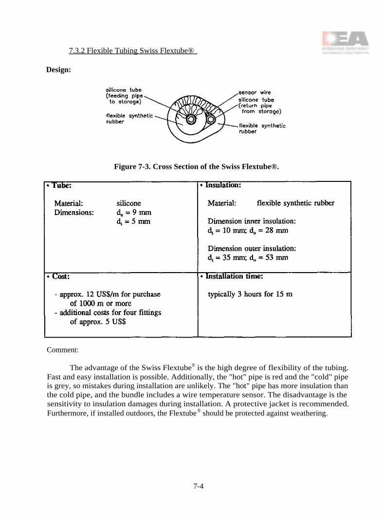
7.3.2 Flexible Tubing Swiss Flextube®
Design:
Figure 7-3. Cross Section of the Swiss Flextube®.
Comment:
The advantage of the Swiss Flextube® is the high degree of flexibility of the tubing.Fast and easy installation is possible. Additionally, the "hot" pipe is red and the "cold" pipeis grey, so mistakes during installation are unlikely. The "hot" pipe has more insulation thanthe cold pipe, and the bundle includes a wire temperature sensor. The disadvantage is thesensitivity to insulation damages during installation. A protective jacket is recommended.Furthermore, if installed outdoors, the Flextube® should be protected against weathering.
7-4

Fittings:
The fittings shown in Figure 7-4 are part of both the collector and the storage tank(refer to Figure 7-1). Rubber tubing can be mounted by sliding the tube onto the nippleportion of the fitting and securing it with the spring loaded clip shown.
Figure 7-4. A Diagram of the Fittings Connecting the Collector / Flextube® and theStorage / Flextube®.
7.3.3. Flexible Tubing Canadian Life-Line®
Design:
Figure 7-5. Cross Section of the Canadian Life-Line®.
7-5

Comment
The Canadian Life-Line® consists of a 1/4 in. copper feeding pipe, a 3/8 in. copper supplypipe, two sensor wires, non-hygroscopic glass fibre insulation, and an exterior PVC jacket.Hot solar collector fluid flows through the small pipe towards the centre of the Life-Line®while the cold solar collector fluid from the heat storage flows in the larger pipe locatedcloser to the outside of the Life-Line®.
Fittings:
Compression fittings (3/8 in. and 1/4 in.) on soldered copper couplings
7.4. Pressure Drop of Different Concepts
Figure 7-6 shows a comparison of calculated pressure drop curves with the fixedtubing, Swiss Flextube®, and Canadian Life-Line® at volume flow rates of 20, 40, and 80Whr. Calculation of pressure drop based on a mixture of 1/3-vol.% Ethyleneglycol and 2/3-vol.% water and one meter length of either supply or feeding pipe.
7.4.1. Discussion of Results Figure 7-6 shows large differences in the pressure dropbetween the fixed and the flexible tubings.
7-6

7-7

7-8

7-9

During system operation, the maximum pressure drop occurs when the fluid in thecold tube is near cold water temperature of the storage and the pump begins to run. At thismoment the temperature of the hot tube is nearly the same as the cold tube.
The following example shows values for a flow rate of 40 Or, a mean temperature of10°C for the return pipe, a mean temperature of 12°C for the feeding pipe and 15 m length ofpiping:
On a sunny day, the cold tube in a low-flow system operates near cold watertemperature of the storage while the hot tube is often in the range of 50 to 70°C. Therefore,the pressure drop of the return pipe from the storage is higher than the pressure drop of thehot feeding pipe.
The following example shows values for a flow rate of 40 9/hr, a mean temperature of10°C for the return pipe, a mean temperature of 60°C for the feeding pipe and 15 m length ofpiping:
These two examples show pressure drop for typical operating conditions. Largedifferences in the pressure drop between the three concepts could be seen.
7.5. Heat Loss
There is a large difference between the operation of a low-flow system and atraditional system. Figure 7-7 shows the radiation and temperatures over time for a typicalsunny day for a low-flow system and a traditional system.
7-10

7-11

The cold tube in the low-flow system operates near ambient air temperatures while thehot tube is often in the range of 50 to 70°C. Therefore, the use of the Canadian and the Swissflexible tubing can result in losses from the hot tube to the environment or heat transfer fromthe hot to the cold tube. In the traditional system, both tubes are operating at the sametemperature range (temperature differences from 5 to 15 K). Both are above the ambient airtemperature, and therefore both have heat losses to the environment.
7.5.1. Results of Heat Loss Measurements Measurements of different tubing underdifferent conditions were taken at various laboratories. The fixed piping and the SwissFlextube® were measured at the Solar Energy Laboratory in Rapperswil/CH while theCanadian Life-Line® and the Swiss Flextube® were measured at the Thermal InsulationLaboratory at the Technical University of Denmark.
The Swiss measurements were taken during the testing of complete systems. The inletand outlet tubing temperatures (return and supply) were measured during the operation of thesystems. Therefore, dynamic and system operation effects, as well as changing weatherconditions, might influence the results. Nevertheless, the values presented show how thedifferent concepts perform under realistic conditions. The mean piping losses for traditionalsystems range from 0.5 to 0.9 WK-1m-1 ; however, most of the values vary over a wide rangein the order of 0.8 WK-1
m-1. The values include losses for both return and supply tubes.Losses for the Swiss Flextube® in a low-flow system are much lower, in the range of 0.35 to0.5
WK -1m-1
.
The investigations done by Denmark were conducted in the laboratory. Values aremuch lower than shown by the Swiss measurements. The losses for either the Canadian Life-Line® or the Swiss Flextube® are in the range of 0.2 to 0.3 WK -1m-1 . The results from thesimulations done by Canada [7-2], [7-4] and Denmark [7-1] show a very good agreement tothe laboratory results from Denmark [7-1].
Due to the different testing conditions of the Swiss and the Danish investigations, theresults are difficult to compare. Nevertheless, the Swiss results show for the flexible tubing ina low-flow system lower losses by a factor of two compared to ordinary piping in aconventional system.
However, the heat loss and the heat exchange between the cold and the hot tube canbe calculated. These calculations can be used for the optimization of insulation of flexibletubing. In the reports [7-1] from Denmark and [7-2] to [7-4] from Canada, calculations ofheat loss coefficient are presented and compared with measurements performed in Denmark[7-1].
7.5.2. Analysis of Heat Losses in Flexible Piping Bundles An analysis of the heattransfer taking place between the components of flexible tubing bundles has been carried outin Canada [7-2, 7-4, 7-5]. In DHW systems employing such tubing bundles, there is athermal performance penalty caused by heat transfer from the hot tube to the cold tube. Thepenalty in system performance happens because the cross heat transfer results in highercollector inlet temperatures, lower collector efficiency, and lower solar energy being delivered
7-12

to the DHW storage system. The Canadian work has shown that the standard Hottel-Whillier-Bliss (HWB) equation can be modified to simultaneously take into account both the pipe heatlosses to the ambient environment and the cross heat transfer between the hot and coldstreams. Parameters in these equations are the thermal resistances between the fluids in thetwo tubes, and between each fluid and the ambient air. Methods are presented in reference[7-5] for both calculating and measuring these thermal resistances.
The parameters in the modified HWB equation were calculated for the case of arepresentative solar D11W system (delivering about 50% of the energy required to supply 300liters/day of water at 60°C) equipped with either of two different flexible tubing bundles:Life-Line-C®, and one consisting of two Nylon-11 tubes inside a PVC cover that contained nothermal insulation. The thermal effects of the tube bundles reduce the net delivered solarenergy by 6 to 14%. The loss in system performance due to cross heat transfer was found tobe practically independent of the loss in performance due to heat losses from the tubes to theambient air. Moreover, heat loss to the ambient air was found to be more detrimental tosystem performance than is heat transfer from the hot to the cold conduit.
7.6. Materials and Requirements
Materials used and requirements for their use are given in Table 7-1.
Table 7-1. Materials.
*Component costs only includes raw material costs without marketing, selling and distribution costs (not theend price to the user)
**To install outdoors UV-protection is needed
7-13
7.6.1. Results of Aging Tests, Experiences in the Field The most important aspectregarding new tubing materials such as plastics or rubber is their durability! Short lifetimeshave been reported in Canada with Nylon-11 tubing. Besides the lifetime of the tubingmaterial itself, the fittings and connecting tubing material are of great importance.Compression fitting leaks in combination with some tubing materials (e.g. Teflon or Nylon)have been reported in Canada [7-3], and 0-ring fittings rather than compression fittings shouldbe used on all plastic tubing connections.
The use of silicone rubber hoses for automotive application is well known. Also,silicone hoses have been used in solar applications for collector couplings for more than 15years. The fittings and clips used to connect the silicone tubing to the collector and storagetank have also been used for many years in similar applications without any problems.
More work is needed to find other suitable materials which are cheaper than thepresent silicone rubber tubes.
7.7. Conclusion
Integrated flexible tubing is of great interest to the development of better domesticsolar water heaters for low-flow applications for the following reasons:
The heat losses are lower by a factor of two or more compared to fixed piping.
Installation time is shorter and therefore cost of installation is lower.
In addition, the cost of silicone hoses with an inner diameter of 10 mm or more fortraditional high-flow systems is very high and the copper alternative for these diameters ismore difficult to install because of its poor flexibility. Therefore, the advantage of flexibletubing is mainly realized in combination with low-flow systems, where smaller diameters areneeded.
Further developments are required to achieve the ideal tubing including:
Finding more appropriate production techniques for lower cost products.
Finding new non-metallic materials with lower prices for the tubes, as well as forthe insulation.
7-14

8. LOW-/HIGH-FLOW TEST
8.1. Introduction
Both experimental and theoretical investigations which compare the thermal performanceof low-flow systems and of traditional high-flow systems have been carried out [8-1], [8-2], [8-3],[8-4].
The designs of the systems, as well as the test conditions, influence the relativeperformances of the systems in experiments. The relative performances of the systems determinedby means of simulation programs are influenced by the suitability of the programs and by theinput data. Therefore, it is extremely difficult to draw general conclusions about the thermalperformance of low-flow and high-flow solar heating systems that are valid for a large varietyof solar heating systems under many operating conditions from a small number of tests orcalculations.
In an experimental comparison of low-flow and high-flow solar heating systems twoapproaches can be followed:
1. Detailed tests of the systems are conducted and the results used for verification ofcalculation models. That is, information about the system properties is collected,followed by performance calculations with the models. In this case, tests will beperformed under extreme conditions in order to characterize the various systemproperties. Subsequent calculation then produces the desired annual system perfor-mance under normal operating conditions.
2. A less thorough investigation of the systems is conducted that does not reveal detailedinformation on system properties or long-term system performance. In this case, testsare performed for normal conditions. A comparison is made only for those conditionsand no extrapolation to yearly performances is made.
Inevitably, the first approach is more extensive and it can reveal much more informationthan the second approach.
In this study the second approach was followed to make results more quickly available.Two different solar DHW systems were tested under the same conditions in an indoor solarsimulator. Both systems were preheating systems. A high- and a low-flow rate was used in thesolar collector loop.
8.2. Description of the Tested Systems
There were two solar pre-heat systems with remote heat storages tested. One used a helixand the other a mantle heat exchanger. For both systems, the solar collector, collector pump andpump control system were the same. The collector circuit was always filled with water, alsoduring periods without sufficient solar irradiation. A check valve prevented undesirable
8-1

backwards thermosiphoning. Both systems are made as suitable as possible for low flow.However, piping and pump are conventional. Figure 8-1 shows both systems and Table 8-1 liststheir main characteristics.
Figure 8-1. Scheme of the Tested DHW Pre-heat Systems.
8-2

Table 8-1. Main Characteristics of the Tested DHW Pre-Heat Systems.
8.3. Test Procedure
The two systems were tested in an indoor solar simulator test facility, [8-6].
Each system was tested at a high-flow rate of about 2.3 //minute corresponding to about0.9 //minute per m2 solar collector and at a low-flow rate of about 0.5 //minute correspondingto about 0.2 //minute per m2 solar collector in the solar collector loop.
The duration of each test was about 3 days. Figure 8-2 shows the total irradiance on thesolar collector and the ambient air temperature of the collector during the 3-day test. The weatherdata were changed every half hour. The irradiance profile was derived from the Test ReferenceYear for De Bilt, the Netherlands.
The ambient air temperature of the heat storage was about 20°C.
8-3


Table 8-2 shows the hot water consumption during the test. The cold water temperaturewas about 15°C and the hot water temperature was 65°C at maximum, i.e. if the temperature ofthe tapped water was above 65°C in the 36.7 ℓ tappings, a smaller water volume was tapped. Inthis case, an energy quantity corresponding to 36.7 ℓ of water, heated from 15°C to 65°C, wastapped. Tappings no. 11 and 12 reveal the energy left in the storage after the three-day period.
Table 8-2. Hot Water Consumption During the Test Period.
8.4. Test Results
The tests and the test results are described in detail in [8-7]. An overview of the resultsis given below. Table 8-3 shows the volumes and energy quantities of the various tap waterdraw-offs for the system with the helix heat exchanger, both for the high and low-flow regime.For every day, subtotals of the volume and energy draw-offs have been made. For the third day,the energy contents in the final large draw-offs have been summed additionally. Moreover, sumshave been made for the draw-offs of all days. Table 8-4 presents the same overview for thesystem with the mantle heat exchanger.
8-5

Table 8-3. Tapped Energy Quantities for the Helix System, Both for High and Low Flow.
Table 8-4. Tapped Energy Quantities for the Mantle System, Both for High and Low Flow.
* A power failure at the test facility on the beginning of Day 3 resulted in a 38-minute delay to the start of the solar irradiance schedule.Test time was extended to accommodate the difference. The first draw for Day 3 scheduled for 8 a.m. was carried out at 11 a.m. Theeffect on the thermal performance of the system is considered to be minor.
8-6

Other test results:
• For the low-flow regime, higher tap water temperatures were measured than with highflow. This result was most pronounced for the mantle system at the midday draw-off,i.e., after a relatively cold start for the top level of the heat storage in the morning. Inthat case, differences in tap water temperatures of over 10 K were observed.
• During the first day, for low flow, the collector pump was in operation for a longerperiod, about half an hour. For the other days, it was about the same. This wasobserved for the helix as well as the mantle system.
Discussion of the results:
• In the discussion of the results below, no comparison is made between the thermalperformance of the helix and mantle system as this was not the aim of the tests. Theaspect under investigation is the difference in thermal performance between low-flowand high-flow operation. This difference has been determined for two specific solarDHW systems.
• For the helix system, the solar fractions for high- and low-flow operation are 46% and47%, respectively, for the draw-offs 2-10. For the mantle system, these fractions are47% and 51%, respectively. These solar fractions correspond well with the annual solarfraction calculated for similar systems in the tests using meteorological data of TRY -De Bilt, Netherlands, for a demand of 110 liters per day, heated from 15°C to 65°C.
• For the helix system, the measured difference in thermal performance between low-flow and high-flow operation is 1 - 3%, depending on whether energy left over in thestorage after draw-off of 330 liters is taken into account and whether draw-off no. 10is considered. Notice the measuring error is about the same.
• For the mantle system, this difference is greater, 6 - 9%.
• Once again, notice that the differences in thermal performance between low-flow andhigh-flow operation as discussed above are valid for the conditions during the three-daytest, and cannot be extrapolated to predict the annual system performance.
8.5. Conclusions
For well-designed, high-flow systems such as the two tested, low-flow operation can obtainslightly greater thermal performance than that of high flow for a choice of realistic meteorologi-cal and draw conditions. The difference in thermal performance between high-flow and low-flowoperation appears to be larger for the tested mantle system.
8-7

8.6. Final Remarks
When designing a system, comparison testing with high and low flow can provideguidance for the choice of flow regime. In this regard, improvement of thermal stratification bychanging from high flow to low flow is of major interest. Valuable information can be obtainedwith respect to the flow regime by these comparative tests without the use of computer models.
In the tests, two different solar pre-heat systems which closely match those on the Dutchmarket have been investigated for specific meteorological and tap water draw-off conditions. Theresults are specific to the systems and the test conditions. Broader conclusions cannot be drawnfor other solar DHW systems and conditions.
Both tested systems had well-stratified heat storages for high-flow as well as for low-flowoperation. Therefore, the thermal advantage of low-flow operation was relatively small.
The difference in thermal performance between low- and high-flow operation is larger ifthe difference in the thermal stratification in the heat storage is greater. In the investigations,thermal stratification was most improved for the tested mantle system.
Furthermore, if a system is optimally designed for low-flow operation, the extra thermalperformance obtained by reducing the flow rate would be greater than found in the tests.
For extensive research on a vast variety of solar DHW system types under differentmeteorological and tap water draw-off conditions, the first approach mentioned in Section 1 mustbe used. Through verification of mathematical models and subsequent calculation of systemperformance annual system performance can be predicted as well. With this approach, modelsneed to be verified on a rather detailed level, which requires considerable effort.
8-8

9. COUNTRY INFORMATION AND STATISTICS
9.1. Introduction
This chapter presents a common set of statistics and other information about each country.A tabular presentation makes it easy to contrast country activities and approaches. Theinformation provided illustrates that circumstances vary widely from country to country andprovides insight into why each country took a different approach to task activities.
9.2. Tables
The country information is organized into four tables.
Table 9-1 provides information on the climate factors that are most relevant to solar DHWsystem performance. As shown, these conditions can vary greatly between and within countries.Although conditions vary only slightly within smaller countries, within larger countries they canvary dramatically.
Table 9-2 lists information on government and utility initiatives, regulations, andconsumer characteristics that can influence solar DHW system design and development paths.
Table 9-3 gives key statistics about the solar industry, consumers, and the economicenvironment in which solar must compete.
Some of the Task 14 Solar DHW Systems Working Group meetings have included a solarDHW industry workshop in which the industries of the host country and Task 14 industryrepresentatives made presentations, exchanged information, and discussed issues and commoninterests. Table 9-4 provides information on these workshops.
For further details on the information presented see Appendix B.

9-2

9-3

9-4

10. BASE CASE AND DREAM SYSTEM
10.1. Introduction
This chapter provides pertinent attributes, key reference quantities, and cost andperformance results for the Base Case and Dream Systems of each country. A tabularpresentation makes it easy to contrast and compare the Base Case and Dream System of eachcountry.
10.2. System Diagrams
Figures 10-1 through 10-12 show each country's Base Case and Dream System. A widevariety in system selection, as well as some common elements, is apparent.
10.3. Tables
Base Case and Dream System information is arranged into three tables.
Table 10-1 provides information for the country Base Cases. The table is organized bysolar DHW system component, and values have been provided for the key attributes of eachcomponent and for the DHW load. The table also gives the rationale for each country's BaseCase selection. A typical system can be quite different in type and size from one country to thenext.
Table 10-2 provides the same information for the Dream System as was given for theBase Case in Table 10-1. It also provides a justification as to why the particular type of solarDHW system was chosen for the Dream System. As can be seen, the Dream Systems vary intype and size from country to country.
Table 10-3 displays cost, performance, and combined cost and performance of the variousBase Case and Dream Systems. It also provides some key reference quantities to enable thereader to gain context for the cost and performance evaluations of each country. The basis forcost estimates are stated. These are applied to the Base Case and Dream System so that resultingcost estimates reflect the real differences between the Base Case and the Dream System, and notinfluences of different production rates, automation, etc. The task goal of fifteen percent or betterfor cost/delivered energy improvement has been achieved for all countries.
For further details on the information presented in the tables see Appendix A.
10-1

Figure 10-1. Canadian Base Case System Diagram.
Figure 10-2. Canadian Dream System Diagram.
10-2

Figure 10-3. Danish Base Case System Diagram.
Figure 10-4. Danish Dream System Diagram.
10-3

Figure 10-5. German Base Case System Diagram.
Figure 10-6. German Dream System Diagram.
10-4

Figure 10-7. The Netherlands Base Case System Diagram.
Figure 10-8. The Netherlands Dream System Diagram.
10-5

Figure 10-9. Common Domestic Hot Water System in Switzerland.
Figure 10-10. Swiss Dream System SOLKIT®.
10-6
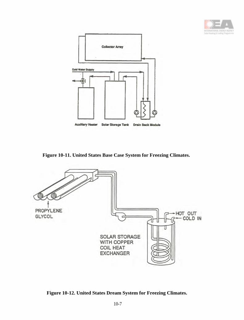
Figure 10-11. United States Base Case System for Freezing Climates.
Figure 10-12. United States Dream System for Freezing Climates.
10-7

10-8

10-9

10-10

10-11

10-12

10-13

10-14

11. CONCLUSIONS AND FINAL REMARKS
The Working Group began its work in 1989 with the purpose of advancing the state-of-the-art in solar DHW systems. The Working Group assembled and developed many designfeatures and components. They analyzed, designed, evaluated, constructed, monitored, andcommercialized different systems incorporating these features and components.
The Working Group's goal of a 15 percent increase in the initial cost to annualperformance ratio (cost/performance), as compared to 1989 practice, was exceeded by allcountries. The Working Group exceeded their cost/performance goal by both lowering cost andincreasing performance. Though the Working Group's chosen primary focus was low-flowsystems, in many cases the improved components also provided similar gains for high-flowsystems. In fact, most of the Working Group's advances can be classified as generalimprovements to solar DHW systems, and not just for low flow.
Cost/performance gains ranged from 20 to 48 percent, depending on the country. Thesegains are a collective result of multiple improvements, including the following:
• Using mantle, in-tank helical, and other improved heat exchangers.
• Using tank-in-tank storages with an inexpensive unpressurized outer drainback tank.
• Using single tanks that combine solar and auxiliary storage.
• Using external auxiliary heaters.
• Modularizing several components, such as pump, controller, heat exchanger, andauxiliary.
• Selecting inexpensive low power consumption pumps.
• Making use of stratification enhancement devices.
• Using lower cost low-flow absorber designs and materials.
• Using easy to install Life-Line® type piping products that have lower net installedcosts.
• Designing CPC reflectors to reduce the number of currently expensive evacuatedtubes.
These components and other features were well designed or logically selected within a systemsoptimization context. All optimization was constrained, often substantially, by the regulationsand practices of each country. Many of these features are the subject of continuing research inthe Working Group countries.
11-1

Other Working Group results were
• For high solar fraction low-flow systems different designs of solarstorage/auxiliary/heat exchanger systems performed about equally. For low solarfractions, there were clear differences. (See Chapter 5 references.)
• Working Group load variability studies have indicated that daily and day-to-dayvariation in DHW load does not significantly impact performance of low-flow systemswith set flow rates.
• Many of the Solar DHW Working Group systems developments have beenimplemented by industry or are gaining acceptance in Task 14 countries. Two of theDream Systems, those of Switzerland and Denmark, are currently beingcommercialized.
• In the near term, improvements from lowering collector flow rates have accumulatedmore on the cost side than on the performance side. However, over the longer termbetter systems may result when all components are designed specifically for low-flowand are properly integrated into the system.
In addition to sharing components and features there was a general and very productiveexchange of ideas. This took place as a matter of course in the meetings and conduct of theTask, as well as more formally through
• exchange of component development information
• comparison of simulation and test results
• study trips and technical tours of installations
• organization of solar industry/Task 14 workshops as a part of nearly all Task meetings.
The Netherlands and Denmark entered into joint model validation and experimentationto resolve a storage/heat exchanger performance issue. The two most promising designs wereexperimentally evaluated in Canada's National Test Facility solar simulator. This resulted in anexacting comparison of the two point designs in a low and a high flow mode and substantiatedthe advantage of using low-flow for the given two systems.
In general the partnership of researcher and industry representative worked well as a taskstructure. The general feeling within the Working Group was that the international collaborationamong researchers and industry has spawned long term relationships which will benefit theworldwide market situation. There was also a general opinion that more was accomplishedcollectively and more was achieved in each country than would have been the case without theWorking Group collaboration.
11-2

12. ACKNOWLEDGEMENTS AND CONTACTS
12.1. Acknowledgements
The low-flow concept explanation chapter was contributed by Canada. The Netherlandscontributed the chapter on collectors, absorbers, and loads. Denmark contributed the chapter onthermal storages, heat exchangers, and auxiliaries. Switzerland contributed the chapter on piping,and Canada contributed the pumps and controller chapter. Denmark and The Netherlandscontributed the chapter on the low-flow/high-flow experiment. The material in the appendiceswas contributed by the various countries.
The editor (United States) refined and assembled the report contributions, including theappendicies and wrote the Base Case and Dream System summary chapter, the summary chapteron country information, the Executive Summary, the Introduction, and the Conclusions.
The following persons contributed material to the report:
Canada Mr. Anthony CaffellMr. Doug McClenahanMr. Allen Carpenter
Denmark Mr. Simon FurboMr. Emanual Brender
Germany Mr. Christian FünfgeldDr. Michael MackDr. Klaus VanoliMr. Uwe Viertel
Netherlands Mr. Teun P. BokhovenMr. Aart de GeusMr. Huib VisserMr. Jeroen van der Linden
Spain Ms. Carmen Granados
Sweden Mr. Per Isakson
Switzerland Mr. Ueli FreiMr. Rene Frey
United States Dr. William DuffMr. Arthur BrooksDr. Pat Burns
12-1

12.2. Contacts
Researchers -- Advanced DHW Systems Working Group
Canada Mr. Anthony CaffellNegentropy Inc.64 Bellhaven RoadToronto, OntarioCANADA M4L 3J61 416 461 8861 Telephone1 416 466 1904 Facsimile
Denmark Mr. Simon FurboThermal Insulation LaboratoryTechnical University of DenmarkBuilding 118DK-2800 LyngbyDENMARK45 45 93 44 77 or 45 45 25 18 57 Telephone45 45 93 17 55 Facsimile
Germany Dr. Klaus Vanoli and Dr. Michael MackISFHInstitute für SolarenergieforschungHameln-EmmerthalAm Ohrberg 11860 EmmerthalGERMANY49 5151 999 523 Telephone49 5151 999 400 Facsimile
Netherlands Mr. Aart de GeusTNO-BOUWP.O. Box 4992600 AA DelftTHE NETHERLANDS31 15 2 608 468 or 31 15 2 608 427 Telephone31 15 2 608 432 FacsimileA.deGeus@ BOUW.TNO.nl
Switzerland Mr. Ueli FreiSPF-ITR
Solarenergie Prut-und ForschungsstelleCH-8640 Rapperswil
12-2

SWITZERLAND41 55 23 46 22 Telephone41 55 222 4400 [email protected]. ch
Spain Ms. Carmen GranadosDpto Energía SolarCampo experimental de El ArenosilloCtra Huelva-MatalascañasKm 27.221130 MazagónHuelvaSPAIN34 59 536003 Telephone34 59 536064 or 34 59 376294 Facsimile
United States Dr. William DuffSolar Energy Applications LaboratoryColorado State UniversityDepartment of Mechanical EngineeringFort Coffins, Colorado 80523USA1 970 493-1321 or 1 970 491-6558 Telephone1 970 491-1055 or 1 970 491-8544 [email protected]
Industry Representatives -- Advanced DHW Systems Working Group
Canada Dr. Peter AllenThermo Dynamics Ltd.81 Thornhill Dr.Dartmouth, N.S.CANADA B3B 1R9902 468 1001 Telephone902 468 1002 Facsimile
Denmark Mr. Emanuel BrenderBatecDanmarksvej 8DK-4681 HerfølgeDENMARK45 56 27 50 50 Telephone45 56 27 67 87 Facsimile
12-3

Germany Mr. Uwe ViertelSolvis EnergiesystemeMarienberger Strasse 13300 BraunschweigGERMANY49 531 2890410 Telephone49 531 874147 Facsimile
Netherlands Mr. Teun P. BokhovenSolair Systems b.v.Middelbok 2102831 BR. GouderakTHE NETHERLANDS31 182 51 0111 Telephone31 182 52 1170 [email protected]
Switzerland Mr. Ueli Frei (address above)
Spain Ms. Carmen Granados (address above)
United States Mr. Arthur BrooksThe Art of Solar9559-A Center AvenueRancho Cucamonga, CA 91730USA1 909 483 2495 Telephone1 909 483 2499 Facsimile
Country Contact Persons
Canada Mr. Doug McClenahanAlternative Energy DivisionNatural Resources Canada580 Booth St.Ottawa, OntarioCANADA K1A 0E4613 996 6078 Telephone613 996 9416 [email protected]
Denmark Mr. Simon Furbo (address above)
Germany Dr. Klaus Vanoli (address above)
12-4

Netherlands Mr. Teun Bokhoven (address above)
Sweden Mr. Per IsaksonRoyal Institute of TechnologyS-100 44 StockholmSWEDEN46 8 790 8422 Telephone46 8 411 8432 [email protected]
Switzerland Mr. Ueli Frei (address above)
Spain Dr. Jose I. AjonaIER-CIEMATAvda Complutense 22, MadridMadrid 28040SPAIN34 1 346 6146 or 34 1 346 6053 Telephone34 1 346 6037 Facsimile
United States Dr. Chuck KutscherNational Renewable Energy Laboratory1617 Cole Blvd.Golden, CO 80401-3393USA1 303 384-7521 Telephone1 303 384-7540 [email protected]
12-5

12-6

APPENDIX A
BASE CASE AND DREAM SYSTEM COUNTRY CONTRIBUTIONS
A-1

A-2

A1. CANADA
A1.1. Base Case System Description
The Base Case system consists of a pair of solar collectors connected together in series,a "Boiler Module," and a solar storage tank. The auxiliary tank is separate. The hydraulicconfiguration is drainback with a propylene glycol antifreeze solution. The collectors areconnected to the heat exchanger and pump module via Life-Line ® tubing, which integrates thesupply and return Nylon tubes with a pair of wires for the delta-T controller. One insulationjacket covers the hot return line, and a second covers the whole assembly. An outer vinyl sleeveprovides environmental protection. The pump is AC powered.
Solar energy is transferred from the heat exchanger to the tank via natural convection inthe sidearm loop connecting the module to the tank. See Figure Al-1.
Figure A1-1. Canadian Base Case System Diagram.
Operating Modes:
The pump is off if the collector is cooler than the tank bottom,or if the solar tank is over temperature.
A-3

The pump is on if the collector is warmer than the tank bottom,and the tank is not over temperature.
Rationale for Choice of Base Case System:
This system has been the one most commonly installed in Canada over the last few years.It was first marketed in late 1988.
A1.1.1. Collector
A1.1.1.1. Collector geometry. The are two collectors connected in series. Internally, thereare eight fin-tubes connected in a series (serpentine) arrangement. Each collector has a singleglazing.
A1.1.12. Collector cover material. The cover is pebble-surface, low-iron glass.
A1.1.13. Absorber material. The absorber consists of a two-layer aluminum fin roll-bonded over a copper tube, which is inflated with air after rolling. The optical surface is analuminum anodized layer impregnated with black nickel to impart selectivity.
A1.1.1.4. Absorber fin/flow design. The 143 mm wide, roll-bond, fin tubes have an 8 mm(hydraulic) bore to facilitate the total design flow rate. Eight such units are connected in seriesin each collector.
A1.1.1.5. Drainback design. The solar collector loop is designed to drainback wheneverthe pump stops.
A1.1.1.6. Frame materials. The frame is fabricated from pieces of aluminum extrusion.
A1.1.1.7. Insulation material. The back of the collector is insulated with a layer of semi-rigid low-outgas fiberglass.
A1.1.1.8. Dimensions, specifications, and properties. Each collector is 2.47 m long by1.20 m wide. The second order efficiency equation follows. This was produced by a numericalmodel whose input was adjusted to make the output fit a graphed test result that reported dT/Gonly to 0.10, for an actual collector.
η = 0.645 - (3.93 + .0070* dT) * dT/G
A1.1.2. Piping Runs
A1.1.2.1. Piping material. The piping material is Nylon.
A1.1.2.2. Insulation material. The pipe insulation material is non-hygroscopic fiberglass.
A-4

A1.1.2.3. Configuration, dimensions, and specifications. The Life-Line®piping consistsof a 6.4 mm outside diameter (OD) (4.8 mm inside diameter (ID)) supply tube wrapped ininsulation and paralleled with the 6.4 mm OD return tube and the two sensor feed wires. Thewhole bundle is wrapped in another layer of insulation, plus an outer PVC environmental jacket.
A1.1.3. Solar Storage and Heat Exchanger
A1.1.3.1. Tank dimensions and specifications. The standard solar tank has a capacity of273 ℓ.
A1.1.3.2. Heat exchanger type and location. The heat exchanger has a coil-in-shellconfiguration, and is incorporated in the "Boiler Module."
A1.1.3.3. Heat exchanger specifications. The heat exchanger has a rating of 380 W/K.
For the current heat exchanger the UA value varies from 100 to 300 W/K as the sidearmflow rate varies.
A1.1.4. Auxiliary
A1.1.4.1. Tank dimensions and specifications. Not applicable. (Separate tank--notincluded in system.)
A1.1.4.2. Auxiliary element location and specifications. Not applicable. (See above.)
A1.1.5. Pump
A1.1.5.1. Flow rates and specifications. The pump is a Model 1521 Procon positivedisplacement, driven by a 120 W GE AC motor. The flow is assumed to be 1.3 ℓ/minute.
A1.1.6. Load
A1.1.6.1. Specifications. The total hot water load is 300 ℓ/day at 50°C.
A1.1.7. Controls
A1.1.7.1. Controller specifications. The controller is a delta-T model DTT84 made byHeliotrope, dT = 10/2 K.
A1.1.7.2. Operating modes.
The pump is off if the collector is cooler than the tank bottom,or if the solar tank is over temperature.
A-5

The pump is on if the collector is warmer than the tank bottom,and the tank is not over temperature.
A1.2. Dream System Description
The Dream System is essentially the same as the Base Case, with the followingexceptions:
• The pump is powered by a 5 W PV panel.
• The collectors have a light-weight absorber design with narrow, small-bore, fm tubesconnected in parallel, and a PTFE convection bather (inner glazing).
• The tubing in the Life-Line® lines is polymeric rather than copper.
• The pump/heat exchanger module is below the solar tank to maximize the flow in thesidearm thermosyphon near the end of a charge cycle.
• The pump is much smaller, cheaper, and more efficient.
• The auxiliary electric element is installed in the outlet header of the heat exchanger,and the auxiliary storage shares the solar tank, which is larger. See Figure A1-2.
Figure A1-2. Canadian Dream System Diagram.
A-6

Operating Modes:
Pump off, due to:
a) Low delta-T.b) Tank at or above temperature limit. (Collector loop drains whenever pump stops.)
Pump on, due to:
c) High delta-T, with pump start-up at high speed (to fill drainback syphon loop).d) High delta-T; normal operation at medium speed and fixed flow.
Auxiliary:
The auxiliary control algorithm is not yet determined. Options include off-peak heating,and in-line boost of solar input during periods of weak insolation to guaranteestratification.
A1.2.1. Collector
A1.2.1.1. Collector geometry. There are two collectors in parallel, with parallel-riser fintubes and headers.
A1.2.1.2. Collector cover material. The outer cover is low-iron tempered glass, with aPTFE inner glazing with a compliant mounting for stress and sag control.
A1.2.1.3. Absorber material. The absorber material is a copper alloy, welded into anintegral, fin-tube shape. The optical surface is a high performance sputtered coating such as theUniversity of Sydney "stainless steel carbide." The surface absorptivity is 0.95, and theemissivity 0.05.
A1.2.1.4. Absorber fin/flow design. The absorber fm tubes have a small bore (2-3 mm),and are connected in parallel between upper and lower horizontal headers.
Drainback design. The collector parallel risers facilitate drainback.
A1.2.1.6. Frame materials. The outside frame will be fabricated in one piece from roll-formed, pre-painted sheet steel or aluminum.
A1.2.1.7. Insulation material. The back and sides will be insulated with isocyanuratefoam or fiberglass.
A1.2.1.8. Dimensions, specifications, and properties. Each collector is about 2.3 m longby 1.15 m wide. The efficiency equation is predicted to be (using the same model as for the BaseCase collectors):
A-7

η = 0.765 - (2.91+ .0024*dT) * dT/G.
A1.2.2. Piping Runs
A1.2.2.1. Piping material. The piping material will be a thermoplastic. It is possible thata proposed newer Nylon composition will be adequate for pressure and temperature.Alternatively, a custom-designed, custom-built, thin-wall PTFE tube with fibre reinforcement mayprove low enough in cost if the PTFE content can be reduced.
A1.2.2.2 . Insulation material. The insulation material will be fiberglass, or polymer foamif its temperature rating can be consistent with the higher temperature ratings of the collectorsand of the PTFE tubing. The pipe heat loss is calculated to be 0.5 W/m 2K, referred to collectorarea.
A1.2.2.3 . Configuration, dimensions, and specifications. The Life-Line® collectorconnection bundle is expected to have 6-7 mm ID supply and return tubes (above), and PVpower and sensor wires, all in an insulated jacket 35-40 mm OD.
A1.2.3. Solar Storage and Heat Exchanger
A1.2.3.1. Tank dimensions and specifications. There will be one tank about 1.5 m highby 0.6 m diameter, and having a capacity of 270 ℓ, about one day's load. The insulation will befiberglass, about 70 mm thick.
A1.2.3.2. Heat exchanger type and location.The heat exchanger will have a fin/tube-in-shell configuration, with potable water on the shell side, antifreeze in the tube side. Its locationwill be external to, and underneath, the tank. The tank-side flow will be by naturalthermosyphon.
A1.2.3.3. Heat exchanger specifications. 300 W/K at 1.3ℓ/minute.
A1.2.4. Auxiliary
A1.2.4.1. Tank dimensions and specifications. None. Auxiliary storage will be integratedwith the solar tank.
A1.2.4.2. Auxiliary element location and specifications. The auxiliary element will belocated, in-line, in the top of the shell of the solar heat exchanger, and have a rating of about 1kW. This location is to enhance thermal stratification, particularly when coupled with innovativeauxiliary control strategies.
A-8

A1.2.5. Pump
A1.2.5.1. Flow rates and specifications. The pump's flow and pressure ratings atoperating speed are 1.3 ℓ/minute at 0.9 atm at 5W. The pump is to be driven at higher speedon system start-up to achieve two atmospheres of pressure to fill the drainback syphon.
A1.2.6. Load
A1.2.6.1. Specifications. The total design load for the system is 300 ℓ/day at 50°C, andis insensitive to the time-of-day due to the high degree of thermal stratification in the tank, aslong as the tank is sized for about one day's load.
A1.2.7. Controls
A1.2.7.1. Controller specifications. The controller is expected to have an on-off delta-Tof 5 K, and includes a 5 W 3-phase driver for the pump.
A1.3. Justification for Dream System Choice
The Dream System will have higher performance due to the lower power pump, moreefficient collector glazing and absorber, and, to some extent, more uniform sidearm flow.
Lower cost will result primarily from the pump price reduction and the small PV panel.There will be an additional saving by not having to buy an auxiliary tank in new installations.
Like the Base Case system, it will be easy to install, reliable and durable.
A1.4. Cost of the Base System
A-9

Solar Energy System Piping $122Solar Energy System Fittings - N/A
A1.4.2. Installation Cost $260
A1.4.3. Operating and Maintenance Costs N/A
A1.5. Performance of the Base Case System
A1.5.1. Thermal Performance. See Table A1-1.
Location for Simulation: TorontoLatitude: 43 °Collector slope: 45 °Collector Aperture Area: 5.67 m2
Table A1-1. Thermal Performance of Canadian Base Case System.
A1.5.2. Reliability and Durability Not available.
A-10


Table A1-2. Thermal Performance of Canadian Dream System.
A1.7.2. Reliability and Durability Not known.
A1.8. Cost Performance Comparisons
Cost Improvement over Base Case: -22%Performance Improvement over Base Case: +48%
Base Case Cost/Performance Ratio $214 / (GJ/an)
Dream System Cost/Performance Ratio: $112 / (GJ/an)
Improvement over the Base Case: 48%
A-12

A2. DENMARK
A2.1. Base Case System Description
A2.1.1. System Diagram/Description of Operating Modes The Base Case system isdesigned as were all Danish marketed systems when the Task began. The solar collector loopis a pressurized loop with an expansion tank and security valve opening at 2.5 bar. Aglycol/water mixture is used as the solar collector fluid.
A diagram of the system is shown in Figure A2-1.
Figure A2-1. Danish Base Case System Diagram.
A2.1.2. Collector
A2.1.2.1. Collector geometry. Each system employs two standard flat-plate solar collectorpanels. The panel has 50 mm of insulation on the back and an air gap of 25 mm in the front.The overall dimensions are: 2.070 m x 1.120 m x 0.090 m. The aperture area of one panel is2.19 m2. The aperture area of the system's solar collectors is 4.38 m2.
A2.1.2.2 Collector cover material. The collector cover consists of 4 mm of temperediron-free glass.
A-13

A2.1.1.3 Absorber material. The absorber consists of Sunstrip® tube plates with a blacknickel selective surface. The tubes are made of copper and the plate of aluminum.
A2.1.2.4 Absorber fins/flow design. The dimensions of the Sunstrip®tube plate are 0.5mm x 143 mm and the tube dimensions are 8 mm x 12 mm. The thickness of the tubes is 0.35mm.
Manifold pipes are located at the bottom and top of the collector. The two pipes areconnected through eight lengthwise parallel Sunstrips ®. An inlet pipe branch is located at thebottom of the collector and is directly connected to the lower manifold pipe. An outlet pipebranch is located at the top of the collector and is directly connected to the upper manifold pipe.
Solar collector fluid enters the absorber through the lower manifold pipe and is pumpedthrough eight Sunstrips® to the upper manifold pipe and out the outlet pipe branch.
A2.1.2.5 Insulation material. To insulate the solar collector panels, a 50 mm thicknessof mineral wool is applied to the back and 15 mm to the edges.
A2.1.2.6 Dimensions/specifications. The measured efficiency of the solar panel, mountedat a tilt of 45° and with an aperture area of 2.19 m 2, is calculated by:
The measured effective heat capacity of the collector is 7 kJ/K/m2.
The empty panel weight is 39 kg.
The volume of solar collector fluid in the panel is 1.9 ℓ .
A2.1.3. Piping Runs
A2.1.3.1. Piping material. Standard 15/13 mm copper pipes are used.
A2.1.3.2. Insulation material. The insulation material is 10 mm PUR foam with a thermalconductivity of 0.03 W/mK.
A2.1.4. Solar Storage and Heat Exchanger
A2.1.4.1 Tank dimensions and specifications. The storage is a hot water tank with twobuilt-in heat exchanger spirals. The lower spiral is connected to the solar collector loop and theupper spiral to the auxiliary energy source.
A-14

The volume of the hot water tank is 295 ℓ, the tank material is St 37-2 steel, the diameteris 500 mm, the height is 1600 mm and the thickness of the tank material is 3 mm. The bottom,sides and top of the tank are insulated with PUR foam. The top is insulated with additionalmineral wool.
The heat storage is enclosed in a cabinet with dimensions 600 mm x 600 mm x 1900 mm.The weight of the empty heat storage is 125 kg and the heat loss coefficient is 2.8 W/K at50°C.
A2.1.4.2. Heat exchanger type and specifications. The bottom heat exchanger spiralconsists of three 6 meter long stainless steel tubes. The heat exchange capacity rate for typicaloperating conditions is approximately 200 W/K.
A2.1.5. Auxiliary Two auxiliary energy supply systems are integrated into the storage.The upper heat exchanger spiral is connected to the auxiliary energy source and heatsapproximately 95 ℓ of water. The heat exchange capacity rate of the auxiliary system duringtypical operating conditions is approximately 300 W/K. The auxiliary heat exchanger spiral isnormally in operation during the winter.
An electric heating element, which heats about 60 ℓ water, is built into the top of the hotwater tank and is normally in operation during summer months.
A2.1.6. Pump
A2.1.6.1. Flow rate and specifications. The circulation pump is a Grundfos UPS 25-40180. Power consumption at normal speed (1) is 30 W, which circulates the solar collector fluidat a volume flow rate of 4 ℓ/minute.
A2.1.7. Load
A2.1.7.1. Specifications. The Danish standard load for determining the state subsidy is200 ℓ water per day heated from 10°C to 45°C.
A2.1.8. Controls
A2.1.8.1 Controller specifications. The differential controller starts and stops thecirculation pump. Both the start and stop temperature differences are adjustable.
A2.1.8.2 Operating modes. Normally, the start temperature difference between the topof the absorber and the bottom of the heat storage is set at 10 K and the stop temperaturedifference is at 2 K.
A-15

A2.2. Dream System Description
A2.2.1. System Diagram and Description of Operating Modes The Dream System is adrainback design, which utilizes water as the solar collector fluid. During operation, an airpocket forms at the top of the mantle. Otherwise the air is located in the solar collector andpipes.
A diagram of the Dream System is shown in Figure A2-2.
Figure A2-2. Danish Dream System Diagram.
A2.2.2. Collector
A2.2.2.1. Collector geometry. One new standard flat-plate solar collector panel is usedas the solar collector for the system. The panel has a 50 mm thick layer of insulation on theback and an air gap of 25 mm in the front. The overall dimensions are 2.820 m x 1.125 m x0.090 m. The aperture area of the panel is 2.99 m2.
A2.2.2.2. Collector cover material. The collector cover consists of 4 mm thick tempered,iron-free glass.
A2.2.1.3. Absorber material. The absorber consists of Sunstrip® tube plates with a blacknickel selective surface. The tubes are made of copper and the plates of aluminum.
A-16

A2.2.2.4. Absorber fins/flow design. The Sunstrip®tube plate dimensions are 0.5 mm x143 mm and the tube dimensions are 8 mm x 12 mm. The thickness of the copper tubes is 0.35mm.
Pipes are located at the bottom and top of the collector manifold pipes. These twomanifold pipes connect eight lengthwise parallel Sunstrips ®. An inlet pipe branch is located atthe bottom of the collector and directly connected to the lower manifold pipe. An outlet pipebranch is located at the top of the collector and is directly connected to the upper manifold pipe.
Solar collector fluid thus enters the absorber through the lower manifold pipe and ispumped through the Sunstrips® to the upper manifold pipe and out the outlet pipe branch.
A2.2.2.5 Drainback design. The collector design makes it possible to drain the absorberin periods of no solar gain. A separate drainback vessel is not part of the system, since themantle serves as the drainback vessel.
A2.2.2.6. Insulation material. The back and edge of the collector are insulated withmineral wool at thicknesses of 50 mm and 15 mm, respectively.
A2.2.2.7. Dimensions/specifications. The measured efficiency of the panel, mounted ata tilt of 45° and with an aperture area of 3.00 m2, is calculated by:
The calculated effective heat capacity of the collector is 7 kJ/K/m2.The empty panel weight is 50 kg.The volume of solar collector fluid in the panel is 2.3 ℓ.
A2.2.3. Piping Runs
A.2.2.3.1. Piping material. A new flexible tubing has been developed. The pipingmaterial consist of a 18/8 mm EPDM pipe and a 18/10 mm EPDM pipe. The smaller pipe isused to transport the solar collector fluid from the solar collector to the heat storage and thelarger pipe is used to transport the solar collector fluid from the heat storage to the solarcollector. The pipes are adjacent and a wire for the control system is placed between the pipes,which are jointly insulated.
A2.2.3.2. Insulation material. The insulation material is a 14 mm thickness of trocellenwith a thermal conductivity of 0.045 W/mK.
A-17

A2.2.4. Solar Storage and Heat Exchanger
A2.2.4.1. Tank dimensions and specifications. The heat storage is a mantle hot water tank.The inlet from the solar collector loop to the mantle is located at the top of the mantle and theoutlet is located at the bottom of the mantle.
The volume of the hot water tank is 150 ℓ, the volume of the mantle is 25 ℓ and the tankmaterial is St 37-2.
The heat storage is insulated with a 5-cm thick layer of PUR foam. The heat losscoefficient of the heat storage at 50°C is 0.9 W/K.
The diameter of the hot water tank is 415 mm and the height is 1200 mm. The diameterof the mantle is 465 mm and the height is 835 mm. The mantle surrounds the bottom of the hotwater tank.
In periods of pump operation, the upper part of the mantle is filled with air. When thepump is not operating, water fills this space.
A2.2.4.2. Heat exchanger type and specifications. The mantle is a part of the solarcollector loop and surrounds a large part of the solar storage tank. This design allows for abuild-up of thermal stratification in the solar storage. The heat exchange capacity rate is highlyinfluenced by the conditions in the solar collector loop and in the heat storage. The heatexchange capacity rate is located in the interval from 60 W/K to 310 W/K.
A2.2.5. Auxiliary Two auxiliary energy supply systems are integrated into the heatstorage of the solar heating system. The upper part of the hot water tank is equipped with a heatexchanger spiral connected to an auxiliary energy source. The heat exchange capacity rate fortypical operating conditions is approximately 300 W/K. The heat exchanger spiral is normallyin operation during the winter.
An electric heating element is located in a pipe connected to the upper part of the mantle.Heat is transferred from the electric heating element to the upper part of the mantle bythermosyphoning. The electric heating element is normally in operation during the summer.
Both auxiliary energy supply systems can heat about 60 ℓ water at the top of the tank.
A2.2.6. Pump
A2.2.6.1. Flow rate and specifications. The circulation pump is a Grundfos 25-40 180.Power consumption in the short start-up periods, at speed 3, is 80 W. During normal operation,at speed 1, the power consumption is 30 W. The volume flow rate of the solar collector fluidis approximately 0.5 ℓ/m.
A-18

A2.2.7. Load
A2.2.7.1. Specifications. The Danish standard load for determining the state subsidy is200ℓ water per day heated from 10°C to 45°C.
A2.2.8. Controls
A2.2.8.1. Controller specifications. The controller has an advanced differentialtemperature control to start and stop the circulation pump.
A2.2.8.2. Operating modes. Normally, the start temperature difference between the topof the absorber and the bottom of the heat storage is 10 K, and the stop temperature differenceis 5 K. When the pump is started, speed 3 is used for a short period in order to fill the solarcollector with water from the mantle. When circulation has started, the speed of the pump isreduced from speed 3 to speed 1.
If the temperature of the solar collector reaches 100°C, the pump speed is increased fromspeed 1 to speed 3.
The pump can be stopped if the water temperature at the top of the tank becomes toohigh. In this way, scalding temperatures may be avoided. The control system will also indicatea lack of fluid in the system or a lack of circulation in periods when circulation is intended.
A2.3. Justification of the Dream System Choice
Utilization of the low-flow and drainback principles makes it possible to reduce the costsof the system, since a number of components can be saved. Additionally, the use of theseprinciples increases the thermal performance of the system.
The design and control system ensures against boiling of the solar collector fluid duringthe summer. The installation of this system is somewhat easier than for the Base Case systemsince glycol is not used as the circulation fluid.
Furthermore, the smaller solar collector area avoids an oversized system for users withlesser hot water needs.
A2.4. Cost of the Base Case System
The costs are:
1 US$ – 6.7 DKK
A-19

A2.5. Performance of the Base Case System
A2.5.1. Thermal Performance The calculated overall yearly performance of a system witha south-facing solar collector tilted at 45°, using data from the Danish Test Reference Year, is5070 MJ. The yearly electric operating needs for the pump and control system are 200 MJ. Thethermal performance is based on detailed tests and on calculations by means of a detailedsimulation program.
A2.5.2. Reliability and Durability The system has been on the market for several yearswithout significant problems, and both reliability and durability have been excellent.
A2.6. Cost of the Dream System
The costs are determined by the manufacturer, who also determined the costs of the BaseCase system.
A-20

A2.6.2. Installation Costs The installation costs for a typical house are about 567US$.
A2.7. Performance of the Dream System
A2.7.1. Thermal Performance The calculated overall yearly performance for a systemwith a south-facing solar collector tilted at 45°, using data from the Danish Test Reference Year,is 5040 MJ. The yearly electric operating needs for the pump and control system are 230 MJ.The thermal performance is determined by means of calculations with a detailed simulationmodel.
A2.7.2. Reliability and Durability Both the reliability and durability of the Dream Systemare expected to be excellent.
A2.8. Cost Performance Comparison
Cost reduction: 3098 US$ - 1892 US$ = 1206 US$
Performance decrease: 5070 MJ/year - 5040 MJ/year = 30 MJ/year
Operating and maintenance cost reduction:~ 20 US$ - 15 US$ = 5 US$
Base Case cost/performance ratio: 611 US$/GJ/year
Dream System cost/performance ratio: 375 US$/GJ/year
Cost/performance improvement: 236 US$/GJ/year ~ 39%
A-21

A-22

A3. GERMANY
A3.1. Base Case Description
A3.1.1. Scheme and Operation Mode Base Case for this evaluation is a SDHW systemdesigned according to the state of the art and public demand during the year 1990 (Figure A3-1).The system layout is based on high demand for quality and durability expected by the Germanpublic and was designed by SOLVIS, the project partner of ISFH in the long-term, low-flowsystem evaluation. Customers expected solar fractions of 100 percent in late spring and earlyfall. The Base Case design reduces surplus energy in summer and, therefore, reduces systemcosts.
Typical specifications are aflat-plate collector, forcedcirculation of antifreeze in thesolar loop, pressurized tank andtwo internal finned, copper pipeheat exchangers for solar andauxiliary energy input.
A3.1.2. Collector Onesingle FPC module with selectivefinned-tube absorber (6 m2), backinsulation 70 mm thick and lowiron glazing is used. Othermanufacturers suggest the use of anumber of standardized smallmodules for the same requiredcollector aperture. To facilitateinstallation, the collector glazing ismounted on site. Figure A3-1. German Base Case System Diagram.
• Collector Geometry
* Overall: 4.76 x 1.45 m26.9 m2
* Absorber 6.03 m2* Mass 60 kg, without glazing* Fluid contents 7.0 ℓ* Heat Capacity 41 kJ/K, with fluid
• Collector Cover Material
* low-iron glazing, structured and tempered (SOLITE from AFG, USA)
* Global transmission 0.91
A-23

• Absorber Material
* Selective, finned tube, copper absorber (MTI, USA)* Galvanic black-chrome layer, α = 0.96 ±.02 , ε = 0.11±0.02
• Absorber Fin/Flow Design
* Fin Cu, 4472 x 112 x 0.3 mm3* Tube Cu, 12.6 x 0.4 mm* Flow Design 12 Fins connected in 2 groups of 6 parallel tubes* Connection Fittings at collector in- and outlet
• Freeze Protection/Corrosion Protection
* 40 percent by volume propylene glycol (greater where necessary).
• Frame Material
* Aluminum
• Insulation Material
* Back 1. layer: 30 mm thickness of PUR foam (CFC-free)2. layer: 40 mm thickness of Mineral Wool
* Side Thermally insulated air gap
• Specifications
• Overheat Protection
* This feature is not necessary because the collector is not damaged by stagnationand the expansion vessel is oversized to accommodate the entire fluid content ofcollector and piping.
A3.1.3. Piping Fairly large copper tube with low pressure drop and rather highinstallation costs is standard.
* Material Cu* Dimensions 18 x 1 mm
A-24

• Insulation
* Temperature and UV- resistant closed cell foam.* Thickness 24 mm* Conductivity 0.04 W/(m•K)
• Specifications
* Typical length 20 m each way* Heat capacity 40 kJ/K* Heat loss 8 W/K
A3.1.4. Solar Storage and Heat Exchanger
• Storage Dimensions and Specifications:
* 400 ℓ cylindrical storage tank designed for use in SDHW systems.* Heat loss reduction by:
All solar and load piping to the storage enters through a flange fromunderneath the storage tank.Closed insulation hood, PUR-foam, CFC-free
* Extended longevity by double-enamel inner coating and active corrosion protectionvia electric current.
Data
* Volume 400 ℓ* Diameter 620 mm, without insulation* Aspect-ratio H/D = 2.4* Insulation λ= 0.04 W/mK
side and bottom: 10 cm thicktop: 15 cm thick
* Mass 93 kg, without HX* Heat Loss UL = 2.1 W/K
• Heat Exchanger
* Internal heat exchanger of finned copper tubing in the bottom of the storage tank.
Data
* U 180 W/K* AHX 1.8 m2* Mass 6.7 kg
A-25
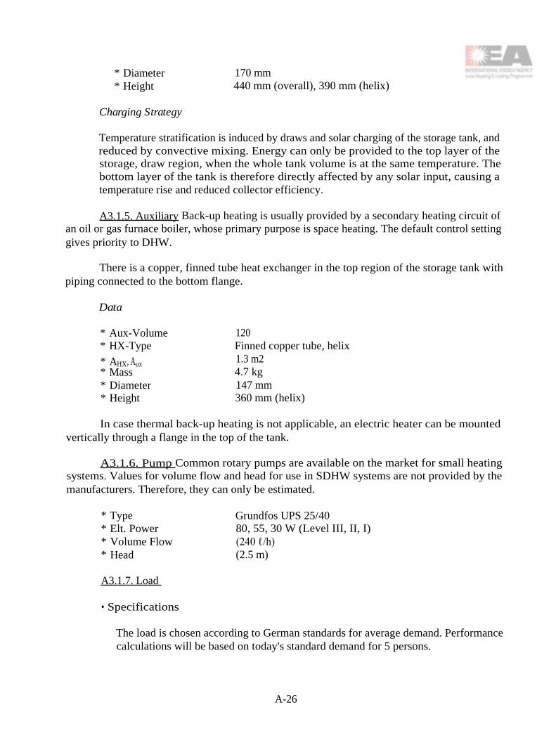
* Diameter 170 mm* Height 440 mm (overall), 390 mm (helix)
Charging Strategy
Temperature stratification is induced by draws and solar charging of the storage tank, andreduced by convective mixing. Energy can only be provided to the top layer of thestorage, draw region, when the whole tank volume is at the same temperature. Thebottom layer of the tank is therefore directly affected by any solar input, causing atemperature rise and reduced collector efficiency.
A3.1.5. Auxiliary Back-up heating is usually provided by a secondary heating circuit ofan oil or gas furnace boiler, whose primary purpose is space heating. The default control settinggives priority to DHW.
There is a copper, finned tube heat exchanger in the top region of the storage tank withpiping connected to the bottom flange.
Data
* Aux-Volume 120* HX-Type Finned copper tube, helix
* AHX, Aux 1.3 m2* Mass 4.7 kg* Diameter 147 mm* Height 360 mm (helix)
In case thermal back-up heating is not applicable, an electric heater can be mountedvertically through a flange in the top of the tank.
A3.1.6. Pump Common rotary pumps are available on the market for small heatingsystems. Values for volume flow and head for use in SDHW systems are not provided by themanufacturers. Therefore, they can only be estimated.
* Type Grundfos UPS 25/40* Elt. Power 80, 55, 30 W (Level III, II, I)* Volume Flow (240 ℓ/h)* Head (2.5 m)
A3.1.7. Load
• Specifications
The load is chosen according to German standards for average demand. Performancecalculations will be based on today's standard demand for 5 persons.
A-26

Demand per 5-Person-Household
* Load 250 ℓ/d* Temperature 45°C* Energy 36.0 MJ/d (10.0 kWh/d)
A3.1.8. Controls
Specifications
Differential temperature control uses absorber and bottom storage temperatures. Storageoverheat protection is achieved by setting the maximum temperature at the lower storageT-sensor and turning off the pumps when the limit is reached.
Operation Mode
*ΔT 5K*ΔT 2K*TSTO, max 95°C
A3.1.9. Rationale for Choice of Base Case The Base Case system is a well-designed,high-performance SDHW system, based on a widely marketed system in Germany in 1990.
A3.2. Dream System Description
A3.2.1. Scheme and Operation Mode The proposed Dream System for one- and two-family houses in Germany is a pump-driven SDHW system with a pressurized tank, Life-Line®piping, and storage stratification, as shown in Figure A3-2. Propylene glycol is used in the solarcircuit as antifreeze and corrosion protection.
• Easy and inexpensive installation
The one-module, flat-plate collector is connected to Flextube® Swiss lifeline-design andmay be installed in or on the roof. On-roof installation is suggested for easy and cheapretrofitting. The premanufactured Solar-Installation-Kit (SIE), as an interface between theFlextube® and storage, integrates all peripheral components such as the circulation pump, control-box, expansion vessel and safety devices. SIE is easily attached to the storage connection pipesthat are brought to the front of the tank and mounted on an installation bracket as shown inFigure A3-3.
A-27

The storage tank is charged by an internal heat exchanger combined with a stratificationmanifold, as it is known from the ISFH long-term, low-flow system evaluation. The heatexchanger and manifold assembly was originally developed for this type of low-flow application(see Section A3.2.4).
A3.2.2. Collector A single-glazed, flat-plate collector with a selective, finned tubeabsorber and a back layer of insulation 70 mm thick is built in one unit for easy installation andreduced thermal losses. To facilitate installation, the collector glazing is to be mounted directlyon site.
• Collector Geometry
* Overall: 3.81 x 1.45 m2, 5.5 m2* Absorber 4.9 m2* Mass 55 kg, without glazing* Fluid content 1.3 ℓ* Heat Capacity 7 kJ/K, with fluid
• Collector Cover Material
* Iron-free glazing, structured and tempered (SOLITE from AFG, USA)* Global transmittance 0.91
A-28
Figure A3-2. German Dream System Diagram.
Figure A3-3. Storage-Installation-Kit and Bracket.

• Absorber Material
* Copper* Sputtered selective layer, α = 0.95, ε = 0.08* Optimized thermal contact between fluid pipe and absorber plate, therefore
increased G value.
• Absorber Fin/Flow Design
* Fin Cu, 3577 x 137 x 0.3 mm3
* Tube Cu, 5 x 0.5 mm* Flow Design 10 fins, connected in 2 groups of 5 parallel fins (See
Figure A3-4)* Connection Internal connection to Flextube®
Figure A3-4. Absorber Flow Design.
• Freeze Protection/Corrosion Protection
* 40 % by volume of propylene glycol (more where necessary)
A-29

Figure A3-5. Flextube® System.
• Frame Material
* Aluminum
• Insulation Material
* Back:
first layer: 30 mm thick PUR Foam (CFC-free)
second layer: 40 mm thick mineral wool* Side Thermally insulated air gap
• Specifications
• Overheat Protection
Overheat protection is not necessary because the collector is stagnation proof and theexpansion vessel is large enough to accommodate the entire fluid content of thecollector and piping.
A3.2.3. Piping The Swiss Flextube® system(Figure A3-5), as presented by SPF-ITR in theirDream System, is well-designed for small solardomestic hot water systems and should be used in theGerman Dream System as well.
Flextube® is fully insulated, consists of twosilicon hoses (di = 5 mm, do = 9 mm) and the wiringfor the absorber T-Sensor. It may be installed in asingle long piece. For trouble-free installation, thehoses are colored grey and red.
The connection to either the collector orSolar-Installation-Kit can be made by a simple nipplefitting and a clip. The durability of this installation,particularly its hoses and fitting clips, must beexamined at collector stagnation temperatures.
• Insulation
The type of insulation used was temperature-resistant, closed-cell foam, which is UV-protected by an outer coating.
A-30

* Conductivity 0.04 W/(m•K)* Collector Inlet 10 mm thickness* Outlet 10 + 10 mm thickness (Refer to Figure A3-5)
• Configuration and Specifications
* Typical length 20 m each wayHeat capacity: ~ 9 kJ/KHeat loss: ~ 7 W/K
* Recc. length < 10 m for loft installation of the storage tank
A3.2.4. Solar Storage and Heat Exchanger
• Storage Dimensions and Specifications
The 300 ℓ storage tank has been developed for use in SDHW systems and, therefore,matches solar application requirements.
Advantages of the Selected Design are:
* Storage stratification is supported by the high aspect ratio.* Heat losses are reduced by:
- All solar and load piping to the storage entering through a flange fromunderneath the storage tank.- A closed insulation hood that is PUR foam, CFC-free.
* Extended longevity by double-enamel inner coating and active corrosion protectionby an external current.
* Easy connection to the SIE by mounting of all pipe connections on theinstallation-bracket.
Data
* Volume 300 ℓ* Diameter 500 mm, without insulation* Aspect-ratio H/D = 3* Insulation λ = 0.04 W/m•K)
side and bottom: 10 cmtop: 15 cm
* Mass 70 kg, without HX* Heat Loss UL= 1.6 W/K
• Heat Exchanger/Storage Management
The chosen heat exchanger, developed by Klaus Lorenz from the Solar EnergyResearch Center (SERC), Sweden, and presented in Sevilla in 1994, is well designedfor low-flow application without the need of an additional pump in the storage loop.
A-31

The design consists of an internal HX with a forced flow of glycol in the solar loop.It has a very low pressure drop and therefore can thermosyphon in the DHW storageloop.
Data
* UHX 600-700 W/K at a solar flow rate of 60-120 ℓ/h* Mass 4 kg* ΔTlog, 5K
Charging Strategy
The storage loop of the heat exchanger leads directly into a stratification manifold thatis specially designed for very low volume flow. Cold water enters the heat exchangerand the tank bottom, and rises by natural convection into the flap valve-operatedmanifold. The silicon flap valves are operated by the density which is induced bytemperature differences between the inside and outside of manifold. Where thistemperature difference diminishes, the valve closest to the tank layer opens and thesolar-heated water is stored in a nearly isothermal region of the tank. Hot water isstored at the top and colder water at the bottom layer of the storage tank. This strictsuppression of thermosyphoning mixing increases the overall efficiency and enablesthe direct use of solar-heated water by charging to or drawing from the top of thetank. Enhanced storage stratification also ensures the reduction in collector inlettemperature necessary for best collector performance at low-flow operation.
A3.2.5. Auxiliary A bare-tube heat exchanger is installed into the top layer of the storagetank, and mounted on the side wall of the tank with piping running inside the insulation downto the installation bracket (Figures A3-2 and A3-3).
Data
* Aux-Volume 85 ℓ (28 percent of storage volume)* HX-Type Bare copper tube, helix
* AHX, Aux1 m2
In case thermal back-up heating is not applicable, an electric heater can be installedhorizontally through a flange in the tank side wall.
A3.2.6. Pump The German Dream System uses a special low-flow, high-head pump,which meets or exceeds the following specifications:
* Volume Flow 60-120 ℓ/h* Maximum Head 20 m* Elt. Power Not exceeding 33 W* ηhydrodynamic 20 percent
A-32

In Task 14, promising work in pump development is currently being conducted by AntonyCaffell of Canada, Ueli Frey of Switzerland, and Klaus Lorenz of Sweden, in order to meet thesespecifications.
A3.2.7. Load
• Specifications
The Dream System load is based on German standards for average demand. Basedon the increased use of water-saving devices in German households, a review of thesestandards is in progress. Performance calculations are based on current demand for5 persons.
Current Standard Demand per 5-Person-Household
* Load 250 ℓ/d* Temperature 45°C* Energy 36.0 MJ/d (10.0 kWh/d)
Recommended Standard Demand per 5-Person-Household
* Load 225 ℓ/d* Temperature 45°C* Energy 32.5 MJ/d (9.0 kWh/d)
A3.2.8. Controls
Specifications
Differential temperature control uses absorber and bottom storage temperatures.Due to a high degree of storage stratification, storage overheat protection must be basedon an evaluation of the storage top temperature, possibly combined with storage bottomtemperature.
Compared to the Base Case system, the Dream System uses fairly high controlthresholds to reduce operating time at low insolation levels, thus reducing tankrecirculation during the day.
Operation Mode
ΔTon
8K* ΔToff 3 K* TSTO, max 95°C
A-33

A3.2.9. Rationale for the Choice of the Dream System
* Increased storage stratification
* Use of special low-flow components for the collector, Life-Line ® piping, pump, heatexchanger, and stratification manifold.
* Ecologically based production of the sputtered selective layer and lowered toxic waste.
* Reduced component and installation costs.
A3.3. Justification of Dream System Choice
The German Dream System combines the advantages of low-flow operation with advancedstorage management economic incentives, and a high annual solar fraction. The Dream Systemis designed for approximately the same solar fraction as the Base Case system but with moreadvanced and reliable components.
Rotary pumps commonly used for space heating and DHW circulation systems aredesigned for high-volume flow and low head, and therefore are not particularly applicable tosmall, low-flow DHW systems. The Dream System will utilize a special low-flow pump withadvanced specifications.
The Dream System also employs a reduced piping diameter in the collector and the Life-Line® piping. Thus, a very small expansion vessel will accommodate the entire volumecirculating in the solar loop (< 5 ℓ with 20 m piping).
Some unique features of the Dream System are:
• High-performance, low-flow absorber with a greatly reduced fluid volume
• Enhanced storage stratification through optimizing tank geometry and the stratificationmanifold
• High performance heat exchanger with thermosyphon storage circuit
• Low-flow pump with optimized hydraulic features and reduced electrical powerconsumption
• Temperature-resistant Life-Line® piping with stagnation-proof installation technology
Major advantages of the Dream System are:
• Decreased collector area for the same annual solar fraction through utilization of ahigh-performance, low-flow collector
A-34

• Enhanced low-flow performance of solar storage through design advancements
• Reduced storage losses through increased insulation and a piping installation flangelocated underneath the tank
• Reduced piping and installation costs through the use of Life-Line ® piping
• Enhanced pump performance and low power consumption in the collector circuit byuse of a low-flow, high-head pump
• Simplified installation due to premanufactured and fewer components
• Extended durability through high component quality
• Reduced pollution during manufacture of the absorber through an improved sputteringprocess, the effect of which increases with production volume
A3.4. Cost of Base Case System
The estimated market price of the components, installation, and maintenance of a BaseCase system in 1994 US$ is outlined below. Marketing and distribution are not included.
A3.4.1. Component Costs
Collector and installation-kit 1,680 $
Storage and both heat exchangers 1,453 $
Solar installation kit, control, pump 625 $
Piping, insulated 300 $
Total component costs 4,058 $
A3.4.2. Typical Installation Costs
Installation material 150 $
Labor 2,400 $
Total installation costs 2,550 $
A-35

A3.4.3. Operating and Maintenance Costs
Operation (180 kWh/a) 31 $
Maintenance 20-100 $
Total 51-131 $
A3.5. Performance of Base Case System
A3.5.1. Thermal Performance The thermal performance of the Base Case system wascalculated with the ISFH program, Version 5.94, extended mode, using a collector slope in therange of a typical roof slope in Germany.
• Specifications
* Location Hannover*Ann. Insolation 953.4 kWh/m2-year, on the horizontal
*
Latitude 52.5° North
*
Absorber Area 6.03 m2
*
Collector Slope 38°, facing south
*
Average Load 36.0 MJ/d (10.0 kWh/d)
*
Demand Profile US Random Profile
*
TCW-Variation Average: 11°C, Maximum: 17°C in August
*
Piping Length 20 m
Table A3-1. Radiation and Annual Performance for the German Base Case System.
A-36

Table A3-2. Annual Values for Friedrichshafen, the Location With the Highest AnnualSolar Insolation in Germany (4523 MJ/m 2yr; 1256.4 kWh/m2yr).
H100 Solar insolation on the collectorQ102 Solar energy delivered to storageQ332 Q102 - Auxiliary (storage losses are solar)SF Solar Fraction, Q332 / QNet Demand
A3.5.2. Reliability and Durability The Base Case system is a high quality system and allof its components have been on the market for a long time. If installed with care, the system isexpected to last over 20 years, just as long as conventional heating systems in Germany. Theflow volume and antifreeze/anticorrosion properties of the solar fluid should be checked regularly.The storage tank is more heavily corrosion protected than ordinary DHW systems. It should betested for proper operation of the active protection system at the same frequency as ordinaryDHW systems. The durability of this system is excellent.
A3.6. Cost of Dream System
The following figures represent the estimated market price of the components, installation,and maintenance of the Dream System in 1994 US$, not including marketing and distribution,assuming the sale of 1000-1500 identical systems per year.
A3.6.1. Component Costs
Collector and installation-kit 1,428 $
Storage and both heat exchangers 1,095 $
Solar installation kit, control, pump 570 $
Piping, insulated 100 $
Total component costs 3,193 $
A3.6.2. Typical Installation Cost
Installation material 150 $
Labor 2,050 $
Total installation costs 2,200 $
A-37

A3.6.3. Operating and Maintenance Costs
Operation (100 kWh/a) 17 $
Maintenance 20-100 $
Total 37-117 $
A3.7. Performance of Dream System
A3.7.1. Thermal Performance The thermal performance of the Dream System has beencalculated with the ISFH Program, Version 5.94, extended mode, using a collector slope in therange of a typical roof slope in Germany.
Specifications
* Location Hannover* Ann. Insolation 953.4 kWh/m2-year, on the horizontal* Latitude 52.5° North* Absorber Area 4.90 m2* Collector Slope 38° facing south* Average Load 36.0 MJ/d (10.0 kWh/d)* Demand Profile US Random Profile* Tcw-Variation Average: 11°C, Maximum: 17°C in August* Piping Length 20 m
Table A3-3. Radiation and Annual Performance for the German Dream System.
A-38

Table A3-4. Annual Values for Friedrichshafen, the Location With the Highest AnnualSolar Insolation in Germany (4523 MJ/m 2yr; 1256.4 kWh/m2yr).
H100 Solar insolation on the collectorQ102 Solar energy delivered to storageQ332 Q102 - Auxiliary (storage losses are solar)SF Solar Fraction, Q332/QNet. Demand
A3.7.2. Reliability and Durability The Dream System is designed and manufactured withthe same quality as the Base Case system. The low-flow collector and storage are of advanceddesign, as are the Base Case system components. The stratification manifold was tested andshowed no excessive degrading for several years.
The durability of the newly designed, low-flow components will be tested before theDream System is marketed. It is believed that these system components will easily pass thestandard durability test.
Problems to be Watched
* Durability of the heat exchanger, expected to be good.* Temperature durability of the silicon piping in case of collector stagnation.* Durability of the Life-Line® piping connection after collector stagnation
The durability of the Dream System is expected to be 20 years, similar to that of the BaseCase system. Routine periodic checking of the solar fluid and active corrosion protection in thestorage tank should be conducted at the same interval as for the Base Case system.
A3.8. Cost Performance Comparison
The total component costs are reduced by 21 percent compared to the Base Case system,with major savings in collector and storage costs. The estimated high volume sales of thestandardized Dream System mainly affects the storage costs (-25 percent), whereas the decreasein collector costs (-15 percent) is due to current differences between the Base Case system 6-m2collector module and the Dream System 5-m2 collector module.
The reduction in installation costs is primarily due to the easy installation of the DreamSystem and is based on current installation costs. The marketing of standardized,premanufactured, easy-to-install Dream Systems stimulates growth of the do-it-yourself consumermarket.
A-39

Table A3-5 shows a cost/performance ratio comparison of the Base Case and DreamSystems at locations in Hannover and Friedrichshafen, Germany. The results indicate that forthe annual overall solar output of the DHW system (Q332 •Ac and system costs, the price ofthe Dream System is 1.73 US$ per saved kWh/yr and 2.23 US$ per saved kWh/yr for the BaseCase system: A savings of .50 US$ per kWh/yr saved (-22 percent). With respect to thecomponent, labor, and sales costs, the relative advantages are about the same for both systems.
Compared with the Base Case system, there is slightly less overall solar energy deliveredby the Dream System in Friedrichshafen, Germany. However, this does not affect the relativecost reduction. Regarding component costs, the savings are .36 US$ per saved kWh/yr, basedon a 1.67 for the Base Case and 1.31 for the Dream System US$ per saved kWh/yr.
Table A3-5. Cost Performance Comparison.
Operating costs are slightly reduced due to a decreased power consumption by the low-flow, high-head pump. Savings, however, are marginal compared to the other cost factors.
A3.9. Conclusions
• The advanced technology and expected market penetration of the Dream Systemprovides a significant reduction in system costs with the same annual solar fraction.
• Low-flow is perhaps too much of a hi-tech solution for small SDHW systems.However, for large multi-user systems, low-flow is the Dream mode of operation.Incorporating the Dream System collector will result in significant savings.
• The simplified installation of the Dream System may open new consumer markets forsystem distribution. Future consumers may be able to purchase a Solar-Energy-Kit
A-40

from a neighborhood building supply store. However, several hurdles impede thedevelopment of this idea: the manufacture of a fool-proof installation and adjustmentkit, testing to determine the reliability of the system, and manufacturer warranty andliability. These are key factors for market sustainability of a Dream System SolarEnergy Kit in Germany. Therefore, any price reduction of residential SDHW systemswithin the German market will be influenced by these factors.
A-41

A-42

Figure A4-1. The Netherlands Base CaseSystem Diagram.
A4. THE NETHERLANDS
A4.1. Base Case System Description
A4.1.1. System Diagram and Description of Operating Modes For the base case weconsidered two Dutch systems on the market at the time of the definition phase of the Task.One system uses a Sunstrip® absorber and a mantle heat exchanger and is still on the market.The other system uses a steel absorber and heat storage with a helix heat exchanger. Both aredrainback systems. The price performance ratio at the time was more or less equal. Becausethe Sunstrip® system did not change much in this past period, we decided to use this systemas the base case.
The diagram of the system isshown in Figure A4-1.
A4.1.2. Collector
A4.1.2.1. Collector geometry.The flat plate collector had 40 mm thickinsulation on the back and an air gap of40 mm in the front. The overalldimensions are 1740 by 1740 mm. Theaperture area is 2.83 m2.
A4.1.2.2. Collector covermaterial. The collector cover consists of3.2 mm low-iron, tempered glass,produced by AFG, USA.
A4.1.2.3. Absorber material. TheSunstrip® absorber is mounted in aparallel configuration. The opticalproperties are α 0.84 and c 0.16-0.18
A4.1.2.4. Absorber fins/flow design. The parallel-strip configuration is mounted ontwo parallel headers. In this way, there is a more or less equal flow distribution.
A4.1.2.5. Drainback design. The drainback design is necessary under present Dutchregulations, in which antifreeze additives require a double-walled heat exchanger. Theperformances of drainback systems in general are even better than closed loop systems withadditives, while the maintenance is easier and cheaper. In general, the drainback vessel isintegrated in the tank, either in the double wall of the tank or in a separate integrated unit inthe storage.
A4.1.2.6. Insulation material. The base case system has 40 mm thick insulation on theback, consisting of polyurethane.
A-43

A4.1.2.7. Dimensions/specifications. The collector efficiency curve is shown in FigureA4-2.
Figure A4-2. Base Case System Collector Efficiency Curve.
A4.1.3. Piping Runs
A4.1.3.1. Piping material. For the piping, normal 12/15 mm copper tubing is used.This material is readily available from every heating installer.
A4.1.3.2. Insulation material. The insulation material applied to the piping is 12 mmSOLFLEX, a heat resistant flexible piping insulation.
A4.1.4. Solar Storage and Heat Exchanger
A4.1.4.1. Tank dimensions and specifications. Various tank designs are being used.Most of the systems are connected to a so-called combi-central heating system. Thesefurnaces supply the central heating system, while at the same time they supply hot water as a"go-through-heater." Because of the cheap and generally available natural gas supply, all aux-iliary heat is supplied by natural gas.
The tank capacity of 110 liters is based on the average Dutch load for a four-personhousehold of 110 liters at 15-65°C/day. The helix heat exchanger is integrated in the tank.
A-44

The tank is made of stainless steel, due to the high mineral content of the average water(DIN. 1.4510).
The test pressure is 13 bar, while the operating pressure of the drinking water sectionis 8 bar.
A4.1.4.2. Heat exchanger type and specifications. The helix heat exchanger is alsomade of stainless steel, 300 W/K. In case the mantle tank is used, it is also made of stainlesssteel.
A4.1.5. Auxiliary
A4.1.5.1. Tank dimensions and specifications. The auxiliary is separated from thesolar system. The solar system operates as a preheater.
A4.1.5.2. Auxiliary element location and specifications. Generally the back-up furnace(combi-heating unit) is located next to the solar system. These systems normally operateunder 20-30 KW.
A4.1.6. Pump
A4.1.6.1. Flow rate and specifications. The pump is a three speed Grundfos pumptype UPS 25/40. The average flow rate is 4 ℓ per minute, with a power consumption ofapproximately 30 W.
Because of the drainback function, the pump is automatically switched to high speedduring the first three minutes of operation in order to pump water to the (empty) collector.After three minutes, the control unit automatically switches the pump to its lowest mode.
A4.1.7. Load
A4.1.7.1. Specifications. The general load under which Dutch SDHW-systems aretested is: 110 ℓ at 15-65°C.
A4.1.8 Controls
A4.1.8.1. Controller specifications. The control unit is a ΔT-controller with thefollowing functions:
Measures temp. difference between the collector and storage. Δ 10°K will switch thepump on its highest mode. Δ2°K will switch the pump off, in order to facilitate the drainbackfunction. The control unit also protects the storage from overheating by switching the pumpoff when it detects a 90°C temperature in the storage.
A4.1.82. Operating modes. See A4.1.8.1.
A-45

Figure A4-3. The Netherlands DreamSystem Diagram.
A4.2. Dream System Description
A4.2.1. System Diagram and Description of Operating Modes The Dream System isan optimization of the Base Case system. The improvements made in the system do have aneffect on the system performance, both under high- and low-flow conditions. The primarybenefits from the design of the Dream System are related to cost effects, as well asperformance improvement. The performance for variations in flow rate are within the limitsof measurement accuracy. See Figure A4-3.
A4.2.2. Collector
A4.2.2.1. Collector geometry. Theflat plate collector has a 55 mm thickness ofinsulation on the back and an air gap of 20mm in the front. The overall dimensionsare 1776 x 1751 x 105 mm. The aperturearea is 2.71 m2.
A4.2.2.2. Collector cover material.The collector cover consist of 3.2 mm low-iron, tempered glass, produced by AFG,USA.
A4.2.2.3. Absorber material. Thecopper absorber is made out of spectralselective material on which the serpentinecopper tubing is soldered. The opticalproperties are: α 96 and ε 12-14.
A4.2.2.4. Absorber fins/flow design.The distance between the tubes of theserpentine configuration is 100 mm. Eachabsorber consists of 4 equal absorber plates, which are interconnected.
A4.2.2.5. Drainback design. The drainback design is needed under present Dutchregulations, in which antifreeze additives require a double-walled heat exchanger. Theperformances of drainback systems in general are even better than closed loop systems withadditives, while the maintenance is easier and cheaper. In general, the drainback vessel isintegrated in the tank, either in the double wall of the tank or in a separate integrated unit inthe storage.
A4.2.2.6. Insulation material. The Dream System, which is resistant to high stagnationtemperatures, has a 55 mm thickness of insulation on the back, consisting of 30 mm CFK-freePUR-foam-board and 25 mm foam-glass.
A-46

A4.2.2.7. Dimensions/specifications. The collector efficiency curve is shown in FigureA4-4.
Figure A4-4. The Netherlands Dream System Collector Efficiency Curve.
A4.2.3. Piping Runs
A.4.2.3.1. Piping material. Normal 8/10 mm copper tubing is used for the piping.Life-Line® is used if the price is reasonable.
A4.2.3.2. Insulation material. The pipe insulation material is 15 mm fiberglass.
A4.2.4. Solar Storage and Heat Exchanger
A4.2.4.1. Tank dimensions and specifications. The optimal tank design consist of aplastic container of approximately 100 liters, with a stainless steel tap water tank. See reportnumber TNO BBI-R0777.
The test pressure is 13 bar, while the operating pressure of the drinking water sectionis 8 bar.
A-47

A4.2.4.2. Heat exchanger type and specifications. There is no heat exchanger in thesystem. The tank itself will function as the drainback vessel. The tap water tank itself is theheat exchanger.
A4.2.4.3. Note:The tank described showed the best results, although the differenceswere of the same order as the accuracy of measurements. Therefore, it is not necessary toactually choose this tank. It is proven that other tanks, provided they are well designed, canperform on an equal basis. In this respect, it is more important to take practical experiences,cost, and regulations into account.
A4.2.5. Auxiliary
A42.5.1. Tank dimensions and specifications. As mentioned under A4.1.4.1 theauxiliary is separated from the solar system. The solar system operates as a preheater.
A4.2.5.2. Auxiliary element location and specifications. Generally, the back-upfurnace (combi-heating unit) is located next to the solar system. These systems normallyoperate at 20-30 KW.
A4.2.6. Pump
A4.2.6.1. Flow rate and specifications. The pump is presumed to be the Canadianlow-flow pump, adapted to drainback conditions. Because of the drainback function, thepump is automatically switched on high speed during the first three minutes of operation, inorder to pump water to the empty collector. After three minutes, the control unitautomatically switches the pump to its lowest mode.
A4.2.7. Load
A4.2.7.1. Specifications. The general load under which Dutch SDHW-systems aretested is 110 liter heated from 15-55°C.
A4.2.8. Controls
A4.2.8.1. Controller specifications. The control unit is a ΔT-controller with thefollowing functions: It measures temperature difference between the collector and storage. Δ10°K will switch the pump to its highest mode. A temperature difference of 1°K will switchthe pump off, in order to facilitate the drainback function. The control unit also protects thestorage from overheating by switching the pump off when it detects a 90°C temperature in thestorage.
A4.2.8.2. Operating modes. See A4.2.8.1.
A-48

A4.3. Justification of Dream System Choice
The Dream System has been developed based on information available directly orindirectly as a result of research carried out in matched-flow systems. It should be mentionedthat a great deal of the improvements do not have a direct impact on the flow of the collectorloop. However, the information generated as a result of the research, led to systemperformance improvements in general. In that sense, the results of the research havesurpassed the original goal, which was to show the effects of low flow. In any case, thejustification of the Dream System is based on the results which came out of the researchcarried out to increase insight about matched- and low-flow principles.
As shown later, the Dream System meets the requirements of cost reduction, as wellas system performance improvement. However, we emphasize the fact that it is not thematched-flow itself which is responsible for the system performance improvements, but thesystem improvements that are the result of the research carried out, which shows performanceimprovements both for low-flow, as well as high-flow, systems.
A4.4. Cost of the Base Case System (US$) (1 US$ Df 1.86)
The cost of the system described is defined as factory costs of the system hardware,including factory overhead and profit. We have not integrated cost for sales, distribution andmarketing into this price analysis. Those costs are considered equal for both the Base Casesystem, and the Dream System.
A4.4.1. Component Costs
The component costs are:
Collector 700 US$Tank 420 US$Pump/control 195 US$Miscellaneous 75 US$
Total system components 1,390 US$
A4.4.2. Installation Costs For the installation costs, we averaged the cost for installingthe systems on an individual basis and installing the systems in a project of more than 10houses in a series. The installation cost are 670 US$.
A4.4.3. Operating and Maintenance Costs The average operating and maintenancecost are:
A-49

Operating cost: 60 KWh 7 US$Maintenance contracts: 10 US$
Total for operating and maintenance: 17 US$
A4.5. Performance of the Base Case System
A4.5.1. Thermal Performance The thermal performance is calculated with the VABI-SDHW (TNO-model) program, using standard tanks and Sunstrip® collectors from 1989. Theoverall yearly performance is 3700 MJ. The electrical operating needs are 60 KWh.
A4.5.2. Reliability and Durability The Base Case system proved to be reliable. Thedurability is questioned for the Sunstrip® absorber in a number of studies. However, practicalexperiences so far have not shown significant problems with systems as installed in the period1985-1990. One manufacturer used an open, drainback loop in the system. This proved to bea source of extra corrosion.
A4.6. Cost of the Dream System (US$)
A4.6.1. Component costs. The component costs are:
Collector 550 US$Tank 385 US$Pump/control 145 US$Miscellaneous 60 US$
Total system components 1,140 US$
Note: This cost is the result of improvements in the components, as well as a pricereduction as a result of the growing number of systems produced. The market situationduring the Base Case was only a few hundred systems a year, while the present marketconsists of a few thousand per year. This implies a partial price reduction based on highvolume effects during production. A major Dutch manufacturer estimates the effects of pricereduction of 50 percent due to high volume effects, while the other 50 percent is caused bymaterial and component improvements.
For these reasons, we define the component costs of the Dream System at 1,265 US$.
A4.6.2. Installation Costs For the installation costs, we have averaged the cost forinstalling systems on an individual basis and installing systems in a project of more than 10houses in a series. The installation cost is 460 US$.
In the same way that we corrected the cost of the components, the reduction ofinstallation costs is not only the result of simpler installation. It is also partly the result of a
A-50

better understanding by installers of solar systems. This is the result, not only of moresystems being installed and more experience, but also of intensive training programs. For thatreason, we also corrected the installation cost with 50 percent of the reduction. The totalinstallation cost of the Dream System is 565 US$.
A4.6.3. Operating and Maintenance Costs The average operating and maintenancecosts are:
Operating cost: 9 KWh 1 US$Maintenance contracts: 10 US$
Total for operating and maintenance: 11 US$
A4.7. Performance of the Dream System
A4.7.1. Thermal Performance The Dream System is evaluated with the VABI-SDHW-program. The yearly performance is calculated at 4160 MJ.
A4.7.2. Reliability and Durability In general, the concept of the Dream Systemincorporates the experience of 15 years of SDHW-applications. Therefore, it is more reliableand durable. Although the pump still has to be tested for durability, it is expected to fulfillthe requirements. The absorber is now made of copper and is very durable.
A4.8. Cost Performance Comparison
If we evaluate the cost/performance information of the Base Case and the DreamSystems, we can conclude that the price has dropped 11.2 percent, while the performance ofthe system has improved by 12.4 percent. The cost for operating and maintenance has beenreduced by almost 30 percent. We conclude that the overall improvement incost/performance is approximately 20 percent, which is more than the target of 15 percent.
Note 1: This evaluation takes into account the effects which come from larger marketvolumes and better installation skills.
Note 2: The effects on the price and performance are to a large extent the result ofresearch carried out on the effects of matched- and low-flow. However, the studies showedno considerable dependence on the flow rate in the system. Therefore, we have labelled theimprovements in price/performance as spin-off effects of the matched flow research.
A-51

A-52

A5. SWITZERLAND
A5.1. Base Case Description
A5.1.1. Scheme and Modes of Operations The common domestic hot water system ispresented in Figure A5-1. The pressurized solar collector loop has forced circulation. Ethyleneor propylene glycol with inhibitors is used for freeze and corrosion protection. The pressurerelief valve opens at 3 bars.
Figure A5-1. Common Domestic Hot Water System in Switzerland.
A5.1.2. Collector
A5.1.2.1. Collector geometry. The standard size of flat-plate collectors used inSwitzerland is about 1.5 to 2 m2. The collector presented here has the following dimensions:
A-53
Overall dimensions 2.027 m x 0.861 mOverall area 1.745 m2
Absorber dimensions 1.877 m x 0.77 m + connectionsAbsorber area 1.48 m2
A5.1.22. Collector cover material. The collector cover material is SOLITE produced byAFG (USA). It is a tempered and structured low-iron glass with a solar transmittance of τ =0.91.
A5.1.23. Absorber material. The black chrome absorber coating is plated by MTI, whilethe fins are roll formed by Northstar. Both companies are in the United States.
Typical performance values: α > 0.94; ε < 0.15
A5.1.2.4. Absorber fins and flow design. The flow design is a grid pattern including 2manifolds (copper tube 18 mm/16 mm) and 7 all-copper fins, 112 mm wide, with a thickness of0.22 mm. The finned tubes have an inner diameter of 11.8 mm, a wall thickness ofapproximately 0.4 mm, and there is just one inlet and outlet per collector (crosswise).
A5.1.2.5. Insulation material. The insulation consists of a 50 mm layer of rockwool onthe back of the collector and a 30 mm layer of rockwool on the sides and edges.
A5.1.2.6. Specifications. The measured efficiency for an absorber area of 1.48 m2:
The weight of the empty collector is 50 kg. The volume of the heat transfer fluid is1.8 ℓ.
A5.1.3. Piping
A5.1.3.1. Piping material. Copper tubes 15/13 mm are used.
A5.1.3.2. Insulation material. The insulation material is synthetic rubber with a thicknessof 16 mm. The synthetic rubber is protected against UV by a special paint.
A5.1.4. Solar Storage and Heat Exchanger
A5.1.4.1. Tank dimensions and specifications. The storage tank holds 500 ℓ. The singleheat exchanger built into the bottom of the storage tank and an electrical backup heater is locatedin the middle. Due to the availability of cheaper electricity during the night, half the tankvolume may be heated at night to ensure enough hot water for the following day.
A-54

The insulation is 100 mm PUR foam on the sides and on the top. The total weight is 130kg. The heat loss coefficient is around 2.5 W/K if the whole storage tank is at 60°C.
A5.1.4.2. Heat exchanger type and specifications. The heat exchanger in the solarcollector loop consists of a smooth tube copper spiral (15/13 mm) with an area of about 1 m 2.The heat exchanger capacity rate is approximately 300 W/K.
A5.1.5. Auxiliary The tank's electric heater, located in the middle of the tank, providesabout 3 kW of power. It operates only at night due to cheaper off-peak electricity and duringthe day only if solar energy is unavailable.
A5.1.6. Pump
A5.1.6.1. Flow rate and specifications. The pump used is a Grunfos UPS 25-40/180, witha power consumption of approximately 60 W on speed 2 and a flow rate of about 30 ℓ/m2/h.
A5.1.7. Freeze Protection Freeze protection is guaranteed by the use of ethylene glycolmixtures as the heat transfer fluid (1 part ethylene glycol to 2 parts water).
A5.1.8. Load
A5.1.8.1. Load specification. The Swiss standard (SIA) asks for 50 ℓ per day of 50°Chot water. Therefore, about 2.5 kWh of energy are needed per person per day.
A5.1.9. Controls
A5.1.9.1. Controller specifications. A differential controller starts and stops the circulationpump. An additional thermostat prevents overheating. Start and stop temperature differences (0-20°C), as well as the maximum temperature (60-90°C), are adjustable.
A5.1.9.2. Operating modes. The start temperature difference is set to about 5°C, whilethe stop temperature is set to 2°C. If the storage tank temperature is above 80°C (adjustable 60-95°C), then the pump does not stop working in the evening until this temperature has decreasedto 80°C.
A5.2. Dream System Description
A5.2.1. Scheme and Modes of Operations The Swiss Dream System is a highly stratified,low-flow system. It consists of a single element collector with only one opening for the inlet andoutlet. The advanced Flextube® tubing connects easily to the collector and storage tank. Thestorage tank is a tank-in-tank design. A stratification device inside the heat exchanger mantleprovides excellent stratification. The solar loop is unpressurized but connected to a smallexternal fluid vessel. The auxiliary heater is introduced in the outer tank. Therefore, depositionof lime is reduced, due to lower specific heating power. See Figure A5-2.
A-55

Figure A5-2. Swiss Dream System SOLKIT ®.
A5.2.2. Collector
A5.2.2.1. Collector geometry. The system has a single collector with about 4.5 m2absorber area. The dimensions are:
Overall dimensions 3.0 m x 1.6 mOverall area 4.8 m2
Absorber dimensions 2.87 m x 1.53 mAbsorber area 4.4 m2
The inlet and outlet use just one opening.
A5.2.2.2. Collector cover material. The cover material used is SOLITE produced by AFG(USA). It is a tempered and structured low-iron glass with a solar transmittance of τ = 0.91.
A-56

A52.2.3. Absorber material. The black chrome absorber coating is plated by MTI, whilethe fins are formed by a newly founded Swiss Company "Innovar." The advantage of this a-fin,is that the tube is formed from a copper strip with a selective coating and, therefore, no tube isneeded.
Typical performance values are α > 0.94; ε < 0.15.
A5.2.2.4. Absorber fins and flow design. The flow design is a serpentine flow pattern.The fans are 110 mm wide, with a thickness of 0.22 mm. The formed tubes have an innerdiameter of 8 mm.
A5.2.2.5. Insulation material. Two layers of insulation are used on the backside of thecollector 30 mm PUR foam and 20 mm rockwool. The sides and edges are insulated with 35mm of rockwool.
A5.2.2.6. Specifications of the collector.
0=0.8-3.5*x-0.010*G*x2
where x = ((Tcoll,in + Tcoll, out) / 2 - Tamb) / G.
The weight of the empty collector without cover is 50 kg. The cover is put on thecollector during installation of the system. The volume of the heat transfer fluid for 4.5 m 2 is2.5 1.
A5.2.3. Piping
A5.2.3.1. Piping material. A new flexible tubing, Flextube®, is developed. Silicon rubberhoses with an inner diameter of about 5 mm are used.
A5.2.3.2. Insulation material. The insulation material is synthetic rubber with a thicknessof 10 mm for the return tube from the collectors. An additional 10 mm thickness is used aroundboth the previously insulated "hot" tube and the "cold" tube. The synthetic rubber is protectedagainst UV by a special paint.
A5.2.4. Solar Storage and Heat Exchanger
A5.2.4.1. Tank dimensions and specifications. The newly designed and manufacturedstorage tank is made of stainless steel. It is basically a tank-in-tank design where the outer tankis equipped with a stratification device. The stratification device leads to a much betterstratification than an ordinary mantle tank. The inner tank meets all necessary Swiss standardrequirements regarding service and maximum pressure or maintenance etc. The outer tank isunpressurized and, therefore, open to the environment.
A-57

Total volume 400 ℓ
Inner Tank volume 300 ℓ
Outer Tank volume 100 ℓ
The side insulation is a 100 mm thickness of soft PUR foam, a 150 mm thickness on top,a 50 mm thickness on the bottom (no FCKW), and a cotton cover.
A5.2.4.2. Heat exchanger type and specifications. The heat exchanger is the area of theinner tank. Including the top, bottom and mantle, it has an area of about 3 m 2. Depending onthe actual temperature, the heat transfer coefficient might reach much higher values than the heatexchanger spiral in the Base Case system.
A5.2.5. Auxiliary Half of the tank volume can be heated by electricity or through anadditional heat exchanger. The position of the electric heater can be adjusted.
A5.2.6. Pump
A5.2.6.1. Flow rate and specifications. An ordinary circulation pump is not able to fulfillthe requirements of a low-flow pump. The flow rate is far too high, while the achievablemaximum pressure is too low. Therefore, a different design, the membrane pump, was chosen.It is capable of delivering the optimal flow rate over a wide range of pressure differences. Thispump is able to reach about 8 bars; however, the rated maximum pressure is 4 bars and thus iscontrolled by a bypass valve. The power consumption is about 20 W.
A5.2.7. Freeze Protection Freeze protection is guaranteed by the use of an ethylene glycolmixture as the heat transfer fluid. (The ratio of ethylene glycol to water is 1:2.)
A5.2.8. Load
A5.2.8.1. Load specifications. The Swiss standard (SIA) is 50 ℓ per person per day of50°C hot water. Therefore, about 2.5 kWh of energy are needed per person per day. The systemis designed for a family of 4-5 people.
A5.2.9. Controls
A5.2.9.1. Controller specifications. A differential controller starts and stops the circulationpump. An additional thermostat in the collector prevents overheating. Start and stop temperaturedifference (0-20°C) are adjustable.
A5.2.9.2. Operating modes. The start temperature difference is set to about 5°C, whilethe stop temperature is set to 2°C. If the collector temperature is above 100°C, the pump stopsworking until the temperature is decreased to about 95°C. During this procedure, the heattransfer fluid in the collector (2.5 ℓ) is evaporated and transported to the tank. At this time, no
A-58
additional fluid enters the collector. Therefore, the collector remains empty during highstagnation temperature, and the heat transfer fluid is not affected by high temperatures.
A5.3. Justification of the Dream System
The SOLKIT project, is under a contract within the official program "Energy 2000," isa technology transfer project to bring new ideas for DHW systems to industry. The aim issimply to reduce the costs of small DHW systems. The approach of the SOLKIT® system iscompletely different from the current state of the art.
The following basic ideas are incorporated in the Dream System design:
• Make use of the low-flow ideas
• The solar fraction for a 4-person family under Swiss conditions (basis Kloten) shouldbe around 50 percent
• All components (including storage tank, collector, advanced tubing etc.) are speciallydesigned and optimized
• A minimum series of 1,000 systems per year is the basis for the production facilitychosen
• The overall costs per kilowatt-hour should be in the same order of magnitude as forelectrical water heaters
• The lifetime of all components should be more than 10 years
• The system should be very easy to install
A5.4. Cost of the Base Case System
A5.4.1. Component Costs (US$)
(Prices without marketing distribution and sales)
Collectors 1200 US$Solar storage unit 1667 US$Pump/Control 267 US$Piping 333 US$Fittings, valves 333 US$Fluids, others 333 US$
Total system components 4,133 US$
A-59

A5.4.2. Installation Costs The installation costs are in the order of 3,000 US$, dependingon the structure of the building.
A5.4.3. Operating and Maintenance Costs
Operating cost 125 kWh/Year at 0.13 US$ per kWh; Total 16 US$
Maintenance cost typically about 84 to 150 US$ per year(this includes one visit from a specialist every 5 years)
A5.5. Performance of the Base Case System
A5.5.1. Thermal Performance The thermal performance of the system is analyzed by thedynamic system testing procedure "DST":
System key parameter Base Case, 6 m2 collector area, 500 Q storage tankWeather data Kloten 1968Collector installation tilt: 45°; azimuth: south, no obstructions.Draw off profile Swiss profile, 10 kWh/daySolar fraction (SFO) 0.50
A5.5.2. Reliability and Durability Excellent, > 20 years!
A5.6. Cost of the Dream System
A5.6.1. Component Costs (US$)
(Prices without marketing, distribution and sales)
Collectors 853Solar storage unit 800Pump/Control 300Piping, fittings 280Fluids, others 233
Total system components 2,466
A5.6.2. Installation Costs The installation costs are in the order of 2,000 US$, dependingon the building type.
A-60

A5.6.3. Operating and Maintenance Costs
Operating costs 50 kWh/Year at 0.13 US$ per kWh; Total 6.50 US$
Maintenance costs typically about 84 to 150 US$ per year(this includes one visit from a specialist every 5 years)
A5.7. Performance of the Dream System
A5.7.1. Thermal Performance The thermal performance of the system is analyzed by thedynamic system testing procedure "DST":
System key parameter SOLKIT® system, 4.5 m2 collector area, 430 Q storage tankWeather data Kloten 1968Collector installation tilt: 45°; azimuth: south, free horizonDraw off profile Swiss profile, 10 kWh/daySolar fraction (SFO) 0.48
A5.7.2. Reliability and Durability The reliability and durability are similar to that ofconventional systems.
A5.8. Cost Performance Comparison
For the above-described conditions, the performance of the Base Case and Dream Systemsis about the same. However, the costs of the Dream System are reduced by more than 30 percentover the Base Case system.
A-61

A-62

A6. UNITED STATES
A6.1. Base Case System Description
A6.1.1. System Diagram and Description of Operating Modes The Base Case system forfreezing climates is shown in Figure A6-1. This system, typical in the United States, consistsof separate solar and auxiliary tanks and a small drainback tank with a helical heat exchangercoil.
Figure A6-1. United States Base Case System for Freezing Climates.
A6.1.2. Collector
A6.1.2.1. Collector geometry. The collector geometry is a conventional, single-glazed flatplate.
A6.1.2.2. Collector cover material. The collector cover is low-iron soda lime glass witha transmittance of 0.91.
A6.1.2.3. Absorber material. Copper with black chrome 0.95/0.15 selective coating isused as the absorber material.
A6.1.2.4. Absorber fin/flow design. A copper fin-tube design with parallel risers is used.The tube inner diameters are 10 mm and the riser tube pitch is 127 mm.
A-63

A6.1.2.5. Freeze protection. A drainback system provides freeze protection.
A6.1.2.6. Frame materials. The frame materials are aluminum.
A6.1.2.7. Insulation material. There is 51 mm of fiberglass on the back of the collectorand 32 mm on the edges.
A6.1.2.8. Dimensions, specifications, and properties.
Number of modules 1Length 2.32 mWidth 1.22 mHeight 0.127 mGross area 2.84 m2Aperture area 2.56 m2Cover transmittance 0.91
The efficiency curve used in the TRNSYS program is
= 0.70 - 3.97T* - 0.0G[T*]2
where T* = [(Tcol,in + Tcol,out)/2 -T amb] / G.
A6.1.2.9. Overheat protection. Collector pump stops when the collector temperature isgreater than 95°C.
A6.1.3. Piping Runs
A6.1.3.1. Piping material. The system uses copper piping.
A6.1.3.2. Insulation material. Piping is insulated with 19 mm polyethylene, closed-cellfoam.
A6.1.3.3. Configuration, dimensions, and specifications.
Specified outer diameter 18 mmTypical length 7.6 m each way
A6.1.4. Solar Storage and Heat Exchanger
A6.1.4.1. Tank dimensions and specifications. There is a glass-lined, steel storage tankhas a volume of 0.189 m3. The tank is insulated with a 51 mm thickness of fiberglass on thesides and bottom, and with foam insulation on top.
A-64

A6.1.4.2. Heat exchanger type and location. In non-freezing climates, no heat exchangeris used. In freezing climates, a helix heat exchanger is located in a small, separate, drainbacktank.
A6.1.5. Auxiliary and Heat Exchanger
A6.1.5.1. Tank dimensions and specifications. A glass-lined, steel storage tank has avolume of 0.189 m3.
The tank is insulated with a 51 mm thickness of fiberglass on the sides and bottom, andwith foam insulation on top.
A6.1.5.2. Auxiliary element location and specifications. There are two 4500-W electricauxiliary U-tube elements, one located approximately 5 cm from the bottom and the otherapproximately 35 cm from the top of the tank.
A6.1.6. Pumps
A6.1.6.1. Flow rates and specifications.
collector side storage side
Type Grunfos UPS 25-40 Grunfos UPS 25-40Flow 6 ℓ/mm 4 ℓ /mmPower 60 W 30 W
A6.1.7. Load
A6.1.7.1. Specifications. The load specifications are 0.265 m3 per day at 55°C in threeequal draws at 8:00, 13:00, and 17:30.
A6.1.8. Controls
A6.1.8.1. Controller specifications. A differential controller is used. Turn-on occurs at2.8°C, turn-off occurs at 0° and where the collector fluid temperature exceeds 95°C.
A6.1.9. Rationale for Choice of Base Case The system type was widely sold in theUnited States.
A6.2. Dream System Description
A6.2.1. System Diagram and Description of Operating Modes The Dream System forfreezing climates is shown in Figure A6-2. Two collector tubes are used with reflectors, ratherthan the four collector tubes, as is currently the case. Since collector storage is smaller,proportionally less fluid is circulated to the auxiliary to avoid overheating.
A-65

Figure A6-2. United States Dream System for Freezing Climates.
A6.2.2. Collector
A6.2.2.1. Collector geometry. The collector geometry consists of integrated collectorstorage evacuated tubes with CPC reflectors.
A6.2.2.2. Collector cover material. Collector covers are soda lime glass cylinders.Reflectors are anodized aluminum with a reflectance of .80.
A6.2.2.3. Absorber material. Stainless steel with black chrome 0.93/0.11 selective coatingis used as the absorber material.
A6.2.2.4. Absorber finIflow design. The absorber fin/flow design consists of a 114 mmcylindrical, integral, collector storage tanks.
A6.2.2.5. Freeze protection. In non-freezing climates, DHW system water is circulatedthrough the collector. In freezing climates, the system is redesigned using propylene glycol inthe collector storage, piping, and the helical heat exchanger of the auxiliary storage.
A6.2.2.6. Frame materials. The frame is constructed of steel.
A6.2.2.7. Insulation material. Insulation is achieved through a vacuum in the evacuatedcollector tubes and a 25 mm thickness of fiberglass in the manifolds.
A-66

A6.2.2.8. Dimensions, specifications, and properties.
Number of tube/reflector units 2Pitch 0.356 mGross area 1.76 m2Aperture area 1.49 m2Heat capacity 2.5 kJ/m2-K
Efficiency curve based on gross area.
= 0.5331 - 1.650T* - 0.0[T*]2
where T* = [(Tcol,in + Tcol ,out)/2 -Tamb] / G.
A6.2.2.9. Overheat protection. Fluid is pumped between the collector and auxiliarystorage at timed intervals and when the high temperature limit is exceeded.
A6.2.3. Piping Runs
A6.2.3.1. Piping material. Pipes are made of thermoplastic.
A6.2.3.2. Insulation material. Piping is insulated with a 9.5 mm thick layer ofpolyethylene, closed-cell foam.
A6.2.3.3. Configuration, dimensions, and specifications.
Specified diameter 20 mmTypical length 8.0 m each way
A6.2.4. Solar Storage and Heat Exchanger
A6.2.4.1. Tank dimensions and specifications. A portion of solar storage is integral toeach collector tube. Each has a volume of 0.197 m 3, with a total volume of 0.384 m 3. Thisintegral storage is connected, via a copper coil heat exchanger with a glass-lined steel storagetank with a volume of 151 m3. The tank is insulated with 51 mm fiberglass on the sides andbottom, and with foam insulation on the top.
A6.2.5. Auxiliary and Heat Exchanger
A6.2.5.1. Tank dimensions and specifications.
Collector Solar Storage Tank material stainless steel glass-lined steelHeight 2.04 m 1.20 mDiameter 0.114 m 0.42 mVolume 0.0189 m3 x 2 0.151
A-67

The tank is insulated with a 5.1-cm thick layer of fiberglass on the sides and bottom andwith foam insulation on top.
A6.2.5.2. Auxiliary element location and specifications. There are two 4500-W electricauxiliary U-tube elements, one located approximately 5 cm from the bottom and the otherapproximately 35 cm from the top of the tank.
A6.2.5.3. Heat exchanger type and location. In non-freezing climates, no heat exchangeris used. In freezing climates, a helix heat exchanger is located in the bottom of the solar storagetank.
A6.2.5.4. Heat exchanger specifications. None.
A6.2.6. Pump
A6.2.6.1. Flow rates and specifications.
Type Task 14 PumpFlow 1.3 //minutePower 5-10 W
A6.2.7. Load
A6.2.7.1. Specifications. The load specifications are 0.265 m3 per day in three equaldraws at 8:00, 13:00, and 17:30.
A6.2.8. Controls
A6.2.8.1. Controller specifications. A photovoltaic driven proportional control is used.Differential control is used for overheating conditions.
Turn-on occurs when collector temperature exceeds 95°C.
A6.3. Justification for Dream System Choice
A high-performance system is used that improves performance and reduces costs.
A6.4. Costs of the Base Case System (1993 US$)
A6.4.1. Component Costs
Collector $350Solar Storage $325Pump/Controls $650
A-68

System Piping/Fittings $300Fluids/Other 0
A6.4.2. Typical Installation Costs $300
A6.4.3. Annual Operating and Maintenance Costs $10
A6.5. Performance of the Base Case System
A6.5.1. Thermal Performance The thermal performance of the system is 7.05 GJ per year.
Location or basis Sacramento, CaliforniaLatitude 38.5°Collector slope 28.5°
A6.5.2. Reliability and Durability According to experience thus far, the reliability anddurability has been excellent.
A6.6. Costs of the Dream System (1993 US$)
A6.6.1. Component Costs
Collector $650Solar Storage integral + $250Pump/Controls $125Solar Energy System Piping/Fittings $125Fluids/Overheat and Over-pressure Prevention/Other $50
A6.6.2. Typical Installation Costs $300
A6.6.3. Annual Operating and Maintenance Costs $10
A6.7. Performance of the Dream System
A6.7.1. Thermal Performance The thermal performance of the system is 8.51 GJ per year.
Location or basis Sacramento, CaliforniaLatitude 38.5°Collector slope 28.5°
A6.7.2. Reliability and Durability The reflector may deteriorate some before the end ofthe system's useful life. Otherwise, the reliability and durability is expected to be about the sameas for the Base Case system.
A-69

A6.8. Cost/Performance Comparisons
The costs for the Dream System have been reduced by $415, or 22%, over that of theBase Case.
The annual performance of the Dream System has been increased by 1460 MJ per year,or 21 percent, over that of the Base Case system.
The annual cost/performance ratio of the Dream System has been improved by 35% overthat of the Base Case system, exceeding the 15 percent Task goal.
A-70

APPENDIX B
COUNTRY REPORTS
B-1

B-2

B1. CANADA
B1.1. Market Overview
Energy consumption by the residential sector accounts for approximately one-fifth of totalenergy use in Canada. Of this, approximately 17 per cent is used to heat water, making waterheating one of the most energy-intensive, domestic, end-use applications.
Eighty per cent of this load, the equivalent of 52 million MWh, is attributed to single-family residences. Of the estimated 6.7 million single-family homes in Canada, 53% rely onelectricity for water heating, with 42% using gas and an additional 4% consuming oil. Table B 1-1provides an overview of the single-family residential water heater market, including province-by-province and national values of water heater installations by fuel type and associated growthrates. It is estimated that a modest number 15,000 homes, currently use solar energy to heatwater.
Table B1-1. Canadian Water Heater Market Data (# in 000's).
Source: Statistics Canada 1993
The average Canadian household consumes 240 ℓ of hot water each day. Althoughwidely varied between individual households, the diversified profile is as shown below in FigureB1-1. In terms of temperature, city 'mains' supplies undergo large seasonal variations that can
B-3

range from a few degrees above zero in February up to 20°C or higher in September. Waterstorage tanks are typically maintained at 55°C to 60°C.
Figure B1-1. Hot Water Usage for a Typical Canadian Household (ℓ/hr).
B1.2. The Solar Industry in Canada
The Canadian solar industry is not as large as it once was due, in large part, to thetermination of federal subsidies and demonstration programs. Nevertheless, there are a couple ofCanadian companies that are producing and/or selling equipment without government subsidies.
Thermo Dynamics of Dartmouth, N.S. is the largest supplier of solar DHW systems inCanada. It produces a micro-flow system with collectors using Sunstrip® absorber technology.
Thermomax in Victoria B.C. supplies solar collectors and systems using evacuated tubesfor DHW, space heating and high-temperature applications. The manufacturing of the tubes takesplace at Thermomax's main production facility in the UK. Other SDHW system manufacturersinclude Solcan of London, Ontario, producing a thermosyphon SDHW system, and PowermatManufacturing of Vancouver, which produces SDHW systems based on an unglazed collectordesign.
B-4

B1.3. Solar Resource
The solar industry's ability to capture a share of the heating market depends on manyfactors which have been addressed by NRCan/Canmet in a recently completed technology andmarket potential assessment for solar thermal applications. One of these factors is the availablesolar radiation which varies significantly both by season and by location within Canada's vastland mass. To get a full appreciation for the solar resource in Canada relative to other lEAmember countries, Figure B 1-2 was constructed showing daily average solar radiation on asurface with tilt equal to latitude. In most cases, a range is also indicated to represent thegeographic variability of the resource within each country. The figure shows a Canadian solarresource which is lower than that for the sunniest climates, such as Australia and the US, yethigher than that of virtually all Northern European climates. For the southern regions of Canada,it varies from a high of 17.4 MJ/m2/day in western Canada to a low of 12.1 MJ/m 2/day inNewfoundland as shown in Figure B1-3.
Figure B1-2. Average Daily Radiation on Surface at Tilt = Latitude for Various lEAMember Countries (MJ/m2-day).
B-5

Figure B1-3. Comparison of Total Solar Radiation at Tilt = Latitude for Various CanadianLocations (MJ/m2/day).
Because of the northerly latitude of Canada, there is a significant variation in solar radiation fromsummer to winter. Figure B1-4 shows the variation in monthly average solar radiation in Torontofor a collector tilt equal to latitude to maximize total yearly radiation.
B-6

Figure B1-4: Solar Resource for Toronto at Tilt = Latitude (kWh/m2/day).
While solar radiation data on a tilted surface is a more useful measure of solar availabilityfor solar heating systems, horizontal radiation measurement is the most common method ofcollecting solar radiation data in many areas of the world. The Atmospheric Environment Serviceof Environment Canada maintains an extensive network of monitoring sites throughout thecountry. Month-by-month average daily values of solar radiation on the horizontal and daytimehigh temperatures are shown in Table B 1-2 for three geographically diverse population centersto indicate typical seasonal climate characteristics.
B-7

Table B1-2. Monthly Average Horizontal Radiation and Daytime High Temperature forSelected Canadian Cities.
B1.4. Energy Costs
The cost of competing conventional sources of energy is another important factor whichdirectly impacts the market potential for residential solar water heaters. Table B1-3 presentsCanadian energy prices as tabulated by Natural Resources Canada (NRCan). The prices aregiven for four geographic areas to account for regional variations: Atlantic Canada, Quebec,Ontario and the West. Provincial energy prices are averaged for the two regions representingmore than one province, and energy prices are not given for those regions where a fuel isunavailable or rarely used.
Table B1-3 also includes estimates of what the fuel prices will be in the year 2010 basedon departmental projections. Electricity prices are projected to increase by roughly 6% in realterms, and residential oil and natural gas prices to increase by 2% and 16%, respectively. Thissharper increase in gas prices is attributed to the high cost of exploration and development of
B-8

new gas sources, and recently depressed prices due to excess gas supply. It should be noted thatall prices are given in dollars per output gigajoule, and that conversion efficiencies were assumedto be 100% for electricity and 50% for both oil and gas heating.
Table B1-3. Typical Canadian Energy Prices ($94/output GJ).
Note: Conversion efficiency of 50% applied to #2 oil and gas
These projected energy price increases, coupled with forecasted reductions in SDHW costs(shown in Figure B1-5), should significantly enhance the market potential for SDHW in Canada.A recent study by CANMET has shown that of the numerous solar end-use applications on themarket today, residential water heating is among the most promising based on its potential energycontribution over the next 20 years. The study identifies a market potential of over 100,000systems for Canada over this time period.
Figure B1-5: Projected Electricity and SDHW Costs (¢/kWh).
B-9

Over 10,000 of these systems are expected to be in place by the year 2000, mainly asback-up to existing electric water heaters. The market is expected to be greatest in provinces witha high residential demand for electricity or high cost, namely Ontario, followed by Quebec andNova Scotia as shown in Figure B 1-6. The market in the remaining provinces is comparativelysmaller, due mainly to the availability of low-cost natural gas or hydro-electricity.
Figure B1-6. Projected SDHW Installations in Canada by Province in Year 2000.
B 1.5. S-2000 Program
The market projections shown above comprise the goals of NRCan/CANMET's S-2000program. Administered by CANMET's Alternative Energy Division, S-2000 is a multi-facetedprogram which supports the R&D needed to realize technology cost/performance improvements,and market development initiatives to introduce solar water heaters to electric utilities andhomeowners. These include workshops for utility officials, and pilot projects with electric utilitiesto finance, install, and monitor SDHW systems. Specific S-2000 program goals include:
• Peak load reduction, cost-effective energy savings and environmental improvementsthrough the installation of residential solar water heaters.
• The transfer of information on SDHW technology and performance to utilities andother technology users.
B-10

• Promoting the development of the SDHW industry, fostering cost and performanceimprovements, and helping to ensure high reliability and service standards forequipment.
CANMET, Nova Scotia Sustainable Economic Development and Thermo Dynamics Ltd.of Halifax are currently cooperating in a field trial to evaluate the aggregate energy, demand andeconomic benefits of Canadian SDHW technology in 60 homes in one Nova Scotia community.Based on results to date, it is estimated that the solar systems being demonstrated will reduce theamount of energy consumed for water heating by about half in a typical NS household,representing savings of $275 in annual energy costs. B.C. Hydro and West Kootenay Power haveinstalled eight systems throughout British Columbia, and Hydro Quebec is close to completinga pilot project to evaluate multi-family residential systems in the Montreal area. BC Hydro isnow considering a larger scale program targeted at the non-integrated areas in its service region,and Hydro Quebec is assessing SDHW for new single-family residential construction.
More recent S-2000 developments include the initiation of pilot projects with two separatemunicipal electric utilities in Ontario, the largest potential Canadian market. In cooperation withCANMET, Guelph Hydro is in the process of installing 100 SDHW systems and low levelmonitoring hardware in its service area to evaluate load-side benefits, customer savings, andprogram take-up when long-term, low-interest fmancing is offered. London Hydro, on its owninitiative, has also conducted a study of a SDHW rental program for its customers with veryfavorable results. More recently, the utility has joined forces with the S-2000 program toimplement a pilot project geared towards validating its feasibility study results. The primaryobjective of this work is to convince its regulatory board of the benefits of a full-scale SDHWsystem rental program based on its existing marketing and distribution channels.
B-11

B-12

B2. DENMARK
B2.1. Introduction
In the period prior to the beginning of the Task 14 project in 1989, only a few hundredsolar water heating systems were installed yearly in Denmark, and only 5 Danish solar collectormanufacturers marketed solar heating systems.
During the progress of the Task 14 project, the number of solar water heating systemsinstalled yearly and the number of solar collector manufacturers have both increased markedlyin Denmark. In 1993, 18 different Danish companies marketed solar heating systems andapproximately 2,500 solar heating systems, with a total solar collector area of 25,000 m2, wereinstalled in Denmark.
The solar water heating market includes a combination of large and small systems.
B2.2. Country Information
The most commonly used energy sources in Denmark are oil, natural gas, and electricity.
The energy prices in US $ are as follows:
• Electricity approx. 0.15US$/kWh• Natural gas approx. 0.65US$/m3• Oil approx. 0.64US$/liter
The use of renewable energy in Denmark is supported by the government, which supportsthe use of biomass (straw, trees etc.), wind energy, and solar energy. The government's aim isto encourage the use of clean energy sources. Some of the most important initiatives are:
• Tax on conventional energy sources• Tax on CO2 emissions• Implementation of the Energy Plan 2000, aiming for an 80% reduction of CO2
emissions• Tax on consumption of water to protect the environment and improve the
quality of water
The combined electrical energy production with biomass is the most accentuated.
In order to decrease the total use of energy in Denmark, regulations have beenimplemented. The most important one is the building code BR 94, which calls for increasinginsulation, making houses air-tight, and decreasing window area.
The primary consumers of solar energy in Denmark are private households and institutionssuch as schools, homes for elderly people, etc. In Denmark, solar energy is an attractive solution
B-13
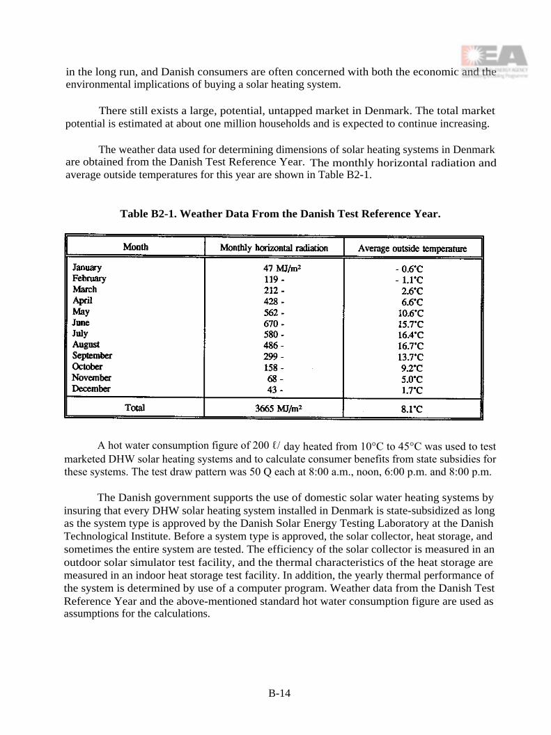
in the long run, and Danish consumers are often concerned with both the economic and theenvironmental implications of buying a solar heating system.
There still exists a large, potential, untapped market in Denmark. The total marketpotential is estimated at about one million households and is expected to continue increasing.
The weather data used for determining dimensions of solar heating systems in Denmarkare obtained from the Danish Test Reference Year. The monthly horizontal radiation andaverage outside temperatures for this year are shown in Table B2-1.
Table B2-1. Weather Data From the Danish Test Reference Year.
A hot water consumption figure of 200 ℓ/ day heated from 10°C to 45°C was used to testmarketed DHW solar heating systems and to calculate consumer benefits from state subsidies forthese systems. The test draw pattern was 50 Q each at 8:00 a.m., noon, 6:00 p.m. and 8:00 p.m.
The Danish government supports the use of domestic solar water heating systems byinsuring that every DHW solar heating system installed in Denmark is state-subsidized as longas the system type is approved by the Danish Solar Energy Testing Laboratory at the DanishTechnological Institute. Before a system type is approved, the solar collector, heat storage, andsometimes the entire system are tested. The efficiency of the solar collector is measured in anoutdoor solar simulator test facility, and the thermal characteristics of the heat storage aremeasured in an indoor heat storage test facility. In addition, the yearly thermal performance ofthe system is determined by use of a computer program. Weather data from the Danish TestReference Year and the above-mentioned standard hot water consumption figure are used asassumptions for the calculations.
B-14

The state subsidy until June 1990 was 30% of the consumer price of the system. SinceJune 1990, the state subsidy for a marketed solar water heating system has been determined bythe equation:
Q1 is found from:110 kWh/year for solar heating systems with a built-in electric heating element.190 kWh/year for solar heating systems with a built-in heat exchanger spiral.300 kWh/year for solar heating systems with both a built-in electric heating
element and a built-in heat exchanger spiral.
A typical DHW solar heating system has a solar collector area of about 4-6 m 2 and a hotwater tank of approximately 200-300 ℓ. The yearly solar fraction of a typical Danish marketedsolar heating system is approximately 60%. The system's cost-inclusive VAT is about 25,000-40,000 DKK. The state subsidy varies from approximately 7,000-11,000 DKK.
The typical DHW solar heating system in Denmark is based on a hot water tank installedwith an auxiliary energy supply system, or systems. An electric heating element and/or a heatexchanger spiral is commonly built into the top of the hot water tank. The heat storage of thesolar heating system and the auxiliary energy system use the same tank.
Prior to the beginning of the Task 14 project, all Danish marketed solar heating systemswere based on the same design, a hot water tank with a built-in heat exchanger spiral situatedat the bottom of the tank. The solar collector fluid is circulated through the heat exchanger spiralwith a volume flow rate of about 1 ℓ/minute per m2solar collector.
B -15

B2.3. Utilization of Knowledge Developed in the Task
The work of the Task 14 project has strongly influenced the development of Danish DHWsolar heating systems. In January 1992, a workshop on the market situation for active solarheating systems was organized by the Danish ISES Section in Lyngby in conjunction with anexpert meeting. Presentations on the market situation in 7 countries were provided by: Teun P.Bokhoven of Solar Systems, b.v. for the Netherlands; Pierre Bremer of Sede SA, for Switzerland;Michael Mack of ISFH Hannover, for Germany; Peter Allen of Thermo Dynamics Ltd, forCanada; Svend Erik Mikkelsen of CowiConsult, for Denmark; Göran Hulima& of Andersen &Hultmark, for Sweden; and Emanuel Brender of Batec A/S, for Denmark. The workshop wasa great inspiration for the 35 participants, mainly Danish solar collector manufactures andconsultants. Most Danish work in the Task 14 project has been concentrated on low-flowsystems and drainback systems.
In 1989, a low-flow system was first introduced to the Danish market by one Danishproducer. This low-flow system consisted of a hot water tank with a mantle welded around aportion of the tank's surface. The solar collector fluid was circulated through the mantle.
The number of solar heating systems installed annually and the sale of Danish low-flowsystems have increased rapidly since the inception of the project. See Figure B2-1.
Today, two manufacturers are marketing low-flow systems, and an additional companyis developing a low-flow system.
Recently, several Danish companies have begun development of DHW solar heatingsystems based on both the low-flow and the drainback principles. Their work is stronglyinfluenced by the work carried out within the Task 14 project. Some of the systems are currentlybeing tested at the Thermal Insulation Laboratory. Others will be tested in the future. In thisway, the testing experience gained from the Task 14 project will be utilized as well.
B2.4. Cost/Performance Improvement
It is expected that the cost/performance ratios for DHW systems based on the low-flowand drainback principles will be about 35% better than the cost/performance ratios for traditionalDanish solar DHW systems.
B-16

Figure B2-1. Number of Installed Solar Heating Systems in Denmark.
B-17


Table B3-1. SDHW - Sales Development.
B3. GERMANY
B3.1. Introduction
In Germany, the market for SDHW systems was greatly influenced by political promotionand the oil crises of 1973/74 and 1978/79. Between 1974 and 1979, the market for solardomestic hot water systems started to boom, resulting in –40,000 m2 of installed collector areaby 1979. In 1980, there was a total of –120,000 m2 of collector area installed. Between 1981and 1987, the solar market dropped to between 15,000 and 25,000 m 2, but it significantlyrebounded after mid-1986 because of the public's growing ecological awareness. Since then, thequestion of energy resources has become more and more a political issue with the onset ofgovernmental subsidy programs in 1986 and 1989.
Sales of SDHW systems haveincreased in Germany since 1980, as shown inTable B3-1, with an approximate share of 15-20 percent for vacuum collectors.
• Total system costs:1,200 - 1,500 US$/m2 (FPC)–2,300 US$/m2 (ETC)
• Today's installation costs:–400 US$/m2
• Average system size: 6-7 m2
• Home-owner installed systems: –40%, decreasing slightly since 1992.
By 1993, there were approximately 6 manufacturers of SDHW systems in Germany andabout 5 companies selling systems with imported collectors.
B3.2. Country Information
• Population
• Area
• Private residences
• One-family houses
• Two-family houses
• Three-family houses and larger
• Average hot water usage
80.7 million 1
357,000 km2
33.7 million 1
7.7 million2
2.6 million2
2.1 million2
45-50 ℓ/Person/d
B-19

• Typical demand temperature 45°C
• Residential electric DHW installations 26.6%price3 0.175 US$/kWh4
• Residential gas DHW installations 38.6%price3 0.036 US$/kWh4
• Residential oil DHW installations 29.5%price3 0.031 US$/kWh4
• Residential district heating DHW inst. 4.5%price3 0.047 US$/kWh4
• Residential solar DHW installations –100,000 systems
1 BMWi, Energiedaten 92/93, Table 12 Germany before unification in 19903 Typical household consumption price, without infrastructure and connection to grids4 BMWi, Energiedaten 92/93, Table 24
B3.2.1. Government Policies A national law, in effect between 1986 and 1991, whichcalled for income tax deductions for energy saving investments in one- and two-family houses.Depending on an individual's income tax rate, this added up to a governmental subsidy of 20-30percent of SDHW system costs.
B3.2.2. State and Utility Programs
• In 1994:
The national program for residential solar DHW systems offers a subsidy of 147US$/m2 collector area up to 882 US$ per system. Due to a limited budget, theprogram collapsed after the first month of operation.
• There has been a regional state subsidy since 1989 with different rates of subsidydecreasing again since 1992. In some counties, the subsidy for solar systems has asmuch as 65 percent of the solar invested costs. In such cases, the budget has beenstrictly limited so that the governmental budget corresponds directly to the size of theSDHW market in that county. Now that the main pilot and demonstration programfor SDHW systems is history, the county subsidy is in the range of 0-25 percent ofthe solar investment costs. The year 1992 had the year with the highest regionalcoverage of subsidy programs at an average level of 25-30 percent subsidy.
• There were a few regional utility programs.
B-20

• Every year the German SDHW Manufacturers Society (DFS) calls for a 48 millionUS$ (0.6 US$ per capita) governmental subsidy program and re-introduction of theincome-tax deduction program.
B3.2.3. Regulations
• All DHW systems with more than 400 9 storage volume without regard to the energysource must undergo Legionnaires Disease prevention cycle by the national board ofsanitary engineering. The whole system must be heated to 60°C once a day.
• The national board of sanitary engineering and the technical supervision council(TUV) stipulates some common safety regulations regarding the operation of DHWsystems.
Table B3-2. Climatic Data for Germany.
B-21

Figure B3-1. Climatic Map for Germany.
B-22

B4. THE NETHERLANDS
B4.1. Introduction
The solar domestic hot water market in the Netherlands has been growing since 1990.This market growth can be explained by three major factors:
a. The Dutch government announced a clear target for the numbers of solar DHWsystems to be installed by the year 2010. In order to meet this target, a marketstimulation program has been started which includes subsidies and advertisingcampaigns aimed at public awareness.
b. Utility companies are actively involved in a larger scale introduction of solar systemsby innovative lease and rental programs as part of their role in environmental actionprograms.
c. The solar industry committed itself to invest in further research and development inorder to bring down the price levels of the installed product to avoid subsidy-dependence.
These three interrelated factors are defined in a "three-party-agreement." The objectiveof the agreement is to reduce the price of SDHW systems by 1998 to a level at which marketmechanisms, without subsidy involvement of any kind, will guarantee a substantial amount ofsolar systems in the hot-water market.
One way in which the research institutes and industry work together towards a betterprice/performance ratio is through implementing the low-flow/matched-flow principles. Theoverall objective is to work towards a 40 percent improvement in price/performance by 1998, ascompared to 1991. This must be accomplished by the research and development of cheapersystems, while maintaining the performance and quality standards, as well as higher marketvolumes with subsequently lower prices. Moreover, the subsidy system will change in 1994towards a subsidy-on-performance, instead of one based on collector area.
B4.2. Country Information
B4.2.1. Statistical Information
Population 1993: 15.5 millionPercent of private homes: Approximately 60%Percent of rental homes: Approximately 40%Average daily hot water demand: 110 ℓ/65°CYearly DHW market: 350,000 systemsNumber of solar manufacturers: 6Current back-up energy source: Over 75% natural gasLatitude: 52 N
B-23

Average hours of sun/yr: 1,500Average hours of sun/day: 4.2Total solar radiation (horiz): 3.9 GJ/m2Climate: Mild Summer/Cold WinterEnergy Prices:
Natural Gas (including VAT): $0.26/m3Electricity (including VAT): $0.12/KWh
B4.2.2. System-Related Conditions Domestic hot water production, both traditional andsolar system-generated, must comply with water authority regulations as formulated the in theDutch working documents from VEWIN (an association of water authorities in the Netherlands).
The current regulation, VEWIN WB 4.4b, states the following:
"Hot water units using indirect heating sources must use a double-walled heatexchanger between the heat transfer medium and the drinking water."
and:
"It is prohibited to use a heat transfer medium in the double-walled heat exchangerwhich is toxic. If a fluid is used as a heat transfer medium, it must be eitherdrinking water or a fluid with a non-toxic ATA certification, which states that itis allowed to be used for this purpose."
In practice, this implies that only low- or no-pressure water drainback systems are allowed.Regulations concerning the use of antifreeze additives may change in the future. All solar DHWsystems must be supplied with the following directions:
B4.3. Utilization of Knowledge Developed in the Task
The results of the work in Task 14 has been implemented to produce a number ofimprovements in solar DHW systems.
B4.3.1. Absorber Based on the work of K.G.T. Hollands et al., a new absorber has beendeveloped to meet both low-flow and high-flow conditions. A number of test units have been
B-24

examined. The one determined to be best was a serpentine copper absorber with 8 mm tubingand 100 fins.
B4.3.2. Load Profiles/Tank Design A discussion on the effect of the load profile and therationale for stratification in the tank led to a few modifications in the tank design. However,it is believed that both mantle and helix heat exchangers can perform equally well, provided theyare designed properly. The work in the Task has greatly improved knowledge in this area.
B4.3.3. Pump/Control The pump defined in the dream system is modeled after theCanadian pump, which is not yet on the market. Some systems use other small pumps whichwere tested as part of the Task work. A control strategy has not been implemented yet. Due tothe high costs, PV power is not yet cost effective under Dutch conditions.
B4.3.4. Flexible Piping Strong interest has created a demand for flexible piping. Thepresent problems of low supply and high prices are expected to be overcome shortly.
B4.4. Cost/Performance Improvement as a Result of Task Work
The cost/performance ratio of solar DHW systems, as indicated in Chapter 8, hasdecreased approximately 20 percent as a result of the implementation of low-flow principles anduse of special components. Another 15 percent price reduction is expected from largerproduction volumes. These price reductions are a necessary condition for further marketpenetration of solar DHW systems in the Netherlands.
B-25

B-26

B5. SWITZERLAND
B5.1. Introduction
The market for thermal solar energy systems in Switzerland is very small. In 1993 just1,000 systems (hot water, space heating and industrial applications) were built.
The common difficulties are a poor economic situation, high and rapidly changing interestrates and very low energy prices.
B5.2. Country Information
The most commonly used energy sources are:
For domestic hot water electricity, oil and natural gas
For space heating oil, natural gas and electricity
The energy prices in US$ are as follows:
Oil 10 US $/GJ
Natural Gas 12 US$/GJ
Electricity, night-time 40 US$/GJ
Electricity, daytime 80 US $/GJ
The use of renewable energy is supported by some Canton governments and also by thefederal government. The federal program called "Energy 2000," has a very broad program toreduce energy needs in general. The thermal solar energy program includes a subsidy fordomestic hot water installations in multiple family houses with more than 5 apartments. Thesubsidy is 200 US$ per square meter of collector area. In the field of small domestic hot watersystems the development of a new low-flow system called SOLKIT (Swiss Dream System seeSection A5) was financed by this program.
The weather data used mostly are based on 3 typical meteorological regions:
Kloten Low lands
Davos Alps
Locarno Southern
B-27

Table B5-1. Switzerland Weather Data.
Hot water consumption is indicated by a "SIA"-standard (SIA: Schweizerischer Ingenieur-und Architekten-Verein):
58 ℓ per person per day heated from 10 to 55°C, or approximately 2.5 kWh per personper day.
B-28

B6. UNITED STATES
B6.1. Introduction
The United States solar industry peaked in 1985, when over 200 collector manufacturersexisted and thousands of systems were being installed each month. From 1985 to 1989, theindustry declined to 12 manufacturers installing 3,500 solar domestic hot water systems per year.
Since the beginning of Task 14, the number of manufacturers has not increased.Approximately 12 companies are currently marketing solar systems, which are being installed ata rate of 4,500 per year.
B6.2. Country Information
United States weather data is provided in Table B6-1. Four locations were chosen totypify the range of weather types throughout the country.
Table B6-1. United States Weather Data.
Hot water consumption in Sacramento is 255 ℓ/day. However, U.S. testing is based onthree equal draws totaling 375 ℓ/day, drawn at 8:00 a.m., noon, and 5:00 p.m.
The U.S. government provides no subsidies or tax credits for solar DHW use, althoughsome states do provide tax credits.
B-29

Most areas of the U.S. require some form of testing of solar equipment. This testing iseither a collector test (ASHRAE 93), a system test (ASHRAE 95), or system-modeledperformance by the Solar Rating and Certification Corporation (SRCC 0G-300). The two U.S.certification groups are SRCC and the Florida Solar Energy Center (FSEC).
State tax credits do not require any specific performance level. However, the SacramentoMunicipal Utility District (SMUD) rebate in that California city is performance-based.
The typical DHW system in Sacramento consists of a four-square-meter collector and a300 ℓ tank. The yearly solar fraction of this type of system is 65 percent and the cost is 2,950US$. SMUD will rebate $800 to the purchaser, leaving a net cost to the purchaser of $2,150.
Sacramento systems are typically of closed-loop design employing either a mantle heatexchanger or a wrap-around heat exchanger on the storage tank. The U.S. requires a double-walled, vented heat exchanger, eliminating in-tank exchangers.
Most systems now installed are two-tank systems, since single-tank system elements onlyheat the top 130 liters of the tank, which doesn't supply sufficient hot water on cloudy days.
B6.3. Utilization of Knowledge Developed in the Task
The work of Task 14 has not yet been utilized by U.S. manufacturers. However, somemanufacturers are considering Life-Lines piping, some aspects of low-flow design, and pumpingvariations. These manufacturers are waiting for more long-term exposure to these techniquesbefore they make a firm commitment such changes. Since the beginning of Task 14, the numberof installations has increased. However, low-flow design has not produced any of this increase.
B6.4. Cost Performance Improvement
It is expected that the work being done on heat exchanger development, low-flow piping,and a new low-flow pump will increase performance and lower costs by 25 percent.
B-30

REFERENCES
[2-1] "Reengineering DHW Systems for Low Flow." K.G.T. Hollands, and D.R. Mandelstam,Proceedings of the 1985 ISRS Congress, p. 544-548.
[4-1] "Low Flow Test Procedure and Results." S. Svendsen, Thermal Insulation Laboratory(DK), Report no. 92-22, August 1992.
[4-2] "Efficiencies of Danish Marketed Solar Collectors for Low Flow Rates." S. Furbo,Thermal Insulation Laboratory (DK), Report no. 92-36, December 1992.
[4-3] "Optimization of the Flat Plate Absorber for Low Flow." K.G.T. Hollands, A.P. Brungerand P.G. Charalambous, University of Waterloo (CAN), 1989.
[4-4] "Optimization of an Absorber Plate Fin Having a Step Change in Local Thickness."K.G.T. Hollands and B.A. Stedman, University of Waterloo (CAN), 1992.
[4-5] "Solar Engineering of Thermal Processes." J.A. Duffie and W.A. Beckman, 2nd edition,John Wiley & Sons, Inc., 1991.
[4-6] "The Thin-fm Flat Plate Collector." P.G. Charalambous, University of Waterloo (CAN),1989.
[4-7] "Low-flow Collector Test Results." J.v.d. Linden and A.C. de Geus, TNO-Bouw (NL),1992.
[4-8] "Variable Plate to Glass Spacing for Solar Collectors." G. Moore, University of Waterloo(CAN), 1986.
[4-9] "Sensitivity of a Single Pass Typical Dutch SDHW System Performance AgainstVariations in Hot Tap Water Load and Profile." A.C. de Geus, TNO-Bouw (NL), 1992.
[4-10] "Sensitivity of Solar Performance of a Typical U.S. SDHW System Versus Variations ofDay to Day Load Profile." W.S. Duff, United States T14 Status Report, 1992.
[5-1] "The Actual Benefits of Thermally Stratified Storage in a Small and Medium Size SolarSystem." C.W.J. van Koppen, J.P.X. Thomas and W.B. Veltkamp, Sun II, ProceedingsISES Biennal Meeting, Atlanta, 1979.
[5-2] "Low Flow Solvarmeanlæg Med en Varmtvandsbeholder og en Ekstern Varmeveksler."P. Carlsson and S. Furbo, Thermal Insulation Laboratory, Technical University ofDenmark, Report no. 91-21, December 1991.
[5-3] "The Suitability of Differently Designed Small DHW Low Flow Solar Heating Systems."S. Furbo, Thermal Insulation Laboratory, Technical University of Denmark, Report no.92-34, December 1992.
1

[5-4] "Thermal Behavior of a Heat Exchanger Coil in a Stratified Storage." J. van Berkel,W.B. Veltkamp and A.B. Schaap, Level Energy Technology, the Netherlands, 1992.
[5-5] "Heat Transfer Phenomena in a Thermally Stratified Energy Storage with Integrated HeatExchanger Coils." J. van Berkel, Level Energy Technology, Report no. 92.12, December1992.
[5-6] "Research Into the Optimal Low Flow Storage and Heat Exchange Combination." J. vander Linden, A.B. Schaap, P. Kratz, TNO-report 93-BBI-R0777, October 1993.
[5-7] "Test Procedures for Short Term Thermal Storages." H. Visser, H.A.L. van Dijk, CEC-report EUR 13118, ISBN 0-7923-1131-0, Kluwer Academic Publishers, 1993.
[5-8] "The Thermal Performance of Small Low Flow Solar Heating Systems." S. Furbo and P.Carlsson, Thermal Insultion Laboratory, Technical University of Denmark, Report no. 91-22, November 1991.
[5-9] "Test Procedures for Heat Storage for Solar Heating Systems." S. Furbo, Int. J. SolarEnergy, Vol. 1, No. 6, 1983.
[7-1] "Tests of the Components of the Solar Boiler System from Thermo Dynamics Ltd." S.Furbo, Technical University of Denmark, Thermal Insulation Laboratory, July 1993.
[7-2] "Modelling the Effects of Life-Line Heat Loss on Flat-Plate Solar Collector Performance."M.A. Anthony, University of Waterloo, Department of Mechanical Engineering, SolarThermal Research Lab Report number ME482.94-1, 25 pp., January 1994.
[7-3] "Development of Flexible Conduit for Solar Domestic Water Heater Systems." Allen,CANMET, Energy Mines and Resources Canada, October 1993.
[7-4] "Analysis of the Heat Transfer in the Life-Line of Solar DHW Systems." K.G.T.Hollands and M.A. Anthony. In McGregor K. Portous C (Eds.) North Sun '94: SolarEnergy at High Latitudes, Sept. 7-9, 1994, Glasgow, Scotland, James & James Press,London, pp. 25-30.
[7-5] "Performance Penalties Caused by Thermal Coupling in SDHW Piping Loops." A.P.Brunger, K.G.T. Hollands, M.A. Anthony, D. Ziolonko, and C. Liang. Presented at ISESSolar World Congress 1995, Harare, Zimbabwe, and submitted for publication in Solar
Energy.
[8-1] "The Actual Benefits of Thermally Stratified Storage in a Small and Medium Size SolarSystem." C.W.J. van Koppen, J.P.S. Thomas and W.B. Veltkamp, In K.W. Boer andB.H. Glenn (Ed.), Sun II Proceedings of the International Solar Energy Society SilverJubilee Congress, Vol. 1, Pergamon Press, New York, 1979.
2

[8-2] "Recent Developments in Low-Flow, Stratified-Tank Solar Water Heating Systems."K.G.T. Hollands, In L. Broman and M. Rönnelid (Ed.), North Sun '88 Proceedings,Swedish Council for Building Research, Stockholm, 1988.
[8-3] "Small Low Flow DHW Solar Heating Systems Status." S. Furbo, Thermal InsulationLaboratory, Technical University of Denmark, Report no. 90-13, 1990.
[8-4] "The Thermal Performance of Small Low Flow Solar Heating Systems." S. Furbo andP.F. Carlsson, Thermal Insulation Laboratory, Technical University of Denmark, Reportno. 91-22, 1991.
[8-5] "Test en Evaluatie van een Collector, Speciaal Ontworpen en Geschikt Voor Low-FlowCondities." ("Test and Evaluation of a Collector Specifically for Low Flow Conditions.")J. van der Linden, TNO report no. B-92-0742, TNO Building and Construction Research,Delft, 1992.
[8-6] "Canada's National Solar Test Facility." G. Norgate, Solar World Forum Conference,Brighton, U.K., 1981.
[8-7] "SDHW High/Low Flow Comparison Testing for IEA Task 14." P. Geisberger and L.E.West, ORTECH Report # 95-E37-B001802-A0524, National Solar Test Facility, ORTECHCorporation, Toronto, Canada, 1995.
3