IEA-ECBCS ANNEX 48 Reversible Air-Conditioning ...
50
IEA-ECBCS ANNEX 48 Reversible Air-Conditioning Overview of cases studies and demonstrations of heat pump systems for tertiary buildings Authors : Marco MASOERO, Politecnico di Torino, Italy Chiara SILVI, Politecnico di Torino, Italy Jacopo TONOLIO, Politecnico di Torino, Italy Internal Reviewer : Philippe ANDRE, Université de Liège, Belgium Date : 2011-05-24
Transcript of IEA-ECBCS ANNEX 48 Reversible Air-Conditioning ...

IEA
-EC
BC
S A
NN
EX
48
Rev
ersi
ble
Air-
Con
ditio
ning
Overview of cases studies and demonstrations of heat pump systems for
tertiary buildings
Authors :
Marco MASOERO, Politecnico di Torino, Italy Chiara SILVI, Politecnico di Torino, Italy
Jacopo TONOLIO, Politecnico di Torino, Italy
Internal Reviewer :
Philippe ANDRE, Université de Liège, Belgium
Date : 2011-05-24
2
Foreword
This document reports on a piece of work carried out in Subtasks 3 “Global performances evaluation and commissioning methods” and 4 “Case studies and demonstration” of IEA Annex 48 and is based upon the contribution of the participating countries. This publication is an official Annex Report. It focuses on the presentation of the case studies analysed by the Annex participants and including reversibility or recovery-based heat pumping solutions. A second part of the report addresses the specific issue of commissioning this kind of technical solutions. It is aimed at building and HVAC designers and operators as well as at researchers in the field. Philippe ANDRE Editor
Operating agents : Jean LEBRUN, Laboratoire de thermodynamique – Campus du Sart-Tilman B49 (P33) B-4000 Liège ([email protected]) Philippe ANDRE, Département des sciences de l’environnement – Avenue de Longwy, 185 B6700 Arlon ([email protected]) Subtask leader : Marco MASOERO, Politecnico di Torino, Corso Duca degli Abruzzi 24, I-10129 Torino, Italy ([email protected])

3
Preface International Energy Agency The International Energy Agency (IEA) was established in 1974 within the framework of the Organization for Economic Co-operation and Development (OECD) to implement an international energy program. A basic aim of the IEA is to foster cooperation among the twenty-five IEA participating countries and to increase energy security through energy conservation, development of alternative energy sources and energy research, development and demonstration (RD&D). Energy Conservation in Buildings and Community Systems The IEA sponsors research and development in a number of areas related to energy. The mission of one of those areas, the ECBCS - Energy Conservation for Building and Community Systems Program, is to facilitate and accelerate the introduction of energy conservation, and environmentally sustainable technologies into healthy buildings and community systems, through innovation and research in decision-making, building assemblies and systems, and commercialization. The objectives of collaborative work ithin the ECBCS R&D program are directly derived from the on-going energy and environmental challenges facing IEA countries in the area of construction, energy market and research. ECBCS addresses major challenges and takes advantage of opportunities in the following areas:
• exploitation of innovation and information technology;
• impact of energy measures on indoor health and usability;
• integration of building energy measures and tools to changes in lifestyles, work environment alternatives, and business environment.
The Executive Committee Overall control of the program is maintained by an Executive Committee, which not only monitors existing projects but also identifies new areas where collaborative effort may be beneficial. To date the following projects have been initiated by the executive committee on Energy Conservation in Buildings and Community ((*) indicates work is completed): Annex 1: Load Energy Determination of Buildings (*) Annex 2: Ekistics and Advanced Community Energy Systems (*) Annex 3: Energy Conservation in Residential Buildings (*) Annex 4: Glasgow Commercial Building Monitoring (*) Annex 5: Air Infiltration and Ventilation Centre Annex 6: Energy Systems and Design of Communities (*) Annex 7: Local Government Energy Planning (*) Annex 8: Inhabitants Behaviour with Regard to Ventilation (*) Annex 9: Minimum Ventilation Rates (*) Annex 10: Building HVAC System Simulation (*) Annex 11: Energy Auditing (*) Annex 12: Windows and Fenestration (*) Annex 13: Energy Management in Hospitals (*) Annex 14: Condensation and Energy (*) Annex 15: Energy Efficiency in Schools (*) Annex 16: BEMS 1- User Interfaces and System Integration (*) Annex 17: BEMS 2- Evaluation and Emulation Techniques (*)

4
Annex 18: Demand Controlled Ventilation Systems (*) Annex 19: Low Slope Roof Systems (*) Annex 20: Air Flow Patterns within Buildings (*) Annex 21: Thermal Modelling (*) Annex 22: Energy Efficient Communities (*) Annex 23: Multi Zone Air Flow Modelling (COMIS) (*) Annex 24: Heat, Air and Moisture Transfer in Envelopes (*) Annex 25: Real time HEVAC Simulation (*) Annex 26: Energy Efficient Ventilation of Large Enclosures (*) Annex 27: Evaluation and Demonstration of Domestic Ventilation Systems (*) Annex 28: Low Energy Cooling Systems (*) Annex 29: Daylight in Buildings (*) Annex 30: Bringing Simulation to Application (*) Annex 31: Energy-Related Environmental Impact of Buildings (*) Annex 32: Integral Building Envelope Performance Assessment (*) Annex 33: Advanced Local Energy Planning (*) Annex 34: Computer-Aided Evaluation of HVAC System Performance (*) Annex 35: Design of Energy Efficient Hybrid Ventilation (HYBVENT) (*) Annex 36: Retrofitting of Educational Buildings (*) Annex 37: Low Exergy Systems for Heating and Cooling of Buildings (LowEx) (*) Annex 38: Solar Sustainable Housing (*) Annex 39: High Performance Insulation Systems (*) Annex 40: Building Commissioning to Improve Energy Performance (*) Annex 41: Whole Building Heat, Air and Moisture Response (MOIST-ENG) (*) Annex 42: The Simulation of Building-Integrated Fuel Cell and Other Cogeneration Systems (FC+COGEN-SIM) (*) Annex 43: Testing and Validation of Building Energy Simulation Tools (*) Annex 44: Integrating Environmentally Responsive Elements in Buildings Annex 45: Energy Efficient Electric Lighting for Buildings Annex 46: Holistic Assessment Tool-kit on Energy Efficient Retrofit Measures for Government Buildings (EnERGo) Annex 47: Cost Effective Commissioning of Existing and Low Energy Buildings Annex 48: Heat Pumping and Reversible Air Conditioning Annex 49: Low Exergy Systems for High Performance Buildings and Communities Annex 50: Prefabricated Systems for Low Energy Renovation of Residential Buildings Annex 51: Energy Efficient Communities Annex 52: Towards Net Zero Energy Solar Buildings Annex 53: Total Energy Use in Buildings: Analysis & Evaluation Methods Annex 54: Analysis of Micro-Generation & Related Energy Technologies in Buildings Working Group - Energy Efficiency in Educational Buildings (*) Working Group - Indicators of Energy Efficiency in Cold Climate Buildings (*) Working Group - Annex 36 Extension: The Energy Concept Adviser (*) Participating countries in ECBCS: Australia, Austria, Belgium, Canada, P.R. China, Czech Republic, Denmark, Finland, France, Germany, Greece, Italy, Japan, Republic of Korea, the Netherlands, New Zealand, Norway, Poland, Portugal, Spain, Sweden, Switzerland,Turkey, United Kingdom and the United States of America.

5
What is Annex 48? Environmental concerns and the recent increase of energy costs open the door to innovative techniques to provide heating and cooling in buildings. Among these techniques, heat pumps represent an area of growing interest. Heat pumping is probably today one of the quickest and safest solutions to save energy and to reduce CO2 emissions. Substituting a heat pump to a boiler may save more than 50% of primary energy, if electricity is produced by a modern gas-steam power plant. The heat pump market was, till now, concentrated on residential buildings. A growing attention is now given to new and existing non-residential buildings where heating and cooling demands co-exist. In many non-residential buildings, an attractive energy saving opportunity consists in using the refrigeration machine for heat production. This can be done by condenser heat recovery whenever there is some simultaneity between heating and cooling demands. When there is no simultaneity, reversibility has to be looked for. What are the main aims of Annex 48 ? The aim of the project is to promote the most efficient combinations of heating and cooling techniques in air-conditioned buildings, thanks to heat recovery and reversible systems. The main goals are: - To allow a quick identification of heat pumping potentials in existing buildings; - To help designers in preserving the future possibilities and in considering “heat pumping” solutions; - To document the technological possibilities and heat pumping solutions; - To improve commissioning and operation of buildings equipped with heat pump systems; - To make available a set of reference case studies.
Which tasks are covered by Annex 48 ? Five tasks are being performed : Subtask 1 : Analysis of building heating and cooling demands and of equipment performances.
- Classification and characterization of existing building stock; - Characterization of existing HVAC systems; - Evaluation of the potential of heat recovery and heat pumping systems, in order to save energy and reduce CO2 emissions; - Development and use of simulation models to identify the heating and cooling demands and the best heat pumping potentials.
Subtask 2 : Design - Development of a design handbook for heat pump systems. - Development of innovative design tools addressed to architects, consulting engineers and installers, in such a way to reach a global optimisation of the whole HVAC system.
Subtask 3 : Global performances evaluation and commissioning methods - Development of evaluation methods devoted to heat pump solutions - Tests with synthetic data and with measured data - Development of computer-based tool for heat pump system operation
Subtask 4 : Case studies and demonstration - Documentation of reference case studies - Use of case studies to test the methods and tools developed in the annex - Conversion of most successful case studies into demonstration projects.
Subtask 5: Dissemination - website - paper work (leaflet, handbooks), - workshops, seminars and conferences.
6
Participants: Université de Liège, Belgique
CEA – INES, France
Ecole des Mines de Paris, France
Greth, France
J.Lebrun Co-operating Agent
S.Bertagnolio Laboratoire de
Thermodynamique Campus du Sart-Tilman B49
(P33) B-4000 Liège
mail : [email protected] [email protected] web : www.labothap.ulg.ac.be
P.André
Co-operating Agent Département des sciences de
l’environnement Avenue de Longwy, 185
B-6700 Arlon mail : [email protected]
web : http://www.dsge.ulg.ac.be/ar
lon/
D. Corgier, V; Renzi Co - Leader of Subtask 1
CEA – INES RDI Laboratoire d'Intégration
Solaire Savoie Technolac - BP 332 50 Avenue du Lac Léman
F - 73377 Le Bourget du Lac mail : [email protected]
[email protected] web : www.cea.fr
D.Marchio, P.Stabat Co - Leaders of Subtask 1
Centre Énergétique et Procédés -
École des Mines de Paris 60 Bd St Michel
F - 75272 Paris Cedex 06 mail :
[email protected] [email protected]
web : www.cep.ensmp.fr
B. Thonon Leader of Subtask 5
Greth Savoie Technolac - BP 302 50 Avenue du Lac Léman
F - 73377 Le Bourget du Lac mail : [email protected]
web : www.greth.fr
Fachhochschule Nürnberg, Germany
HLK Stuttgart GmbH, Germany
TEB GmbH, Germany Politecnico di Torino, Italy
W. Stephan Co – Leader of Subtask 2
Ieg Intstitut für Energie and Gebäude
Kesslerplatz 12 D – 90489 Nürnberg
mail : [email protected]
J. Schmid Co – Leader of Subtask 2
HLK Stuttgart GmbH Pfaffenwaldring 6A D – 70569 Stuttgart
mail : [email protected]
web : www.hlk-stuttgart.de
M. Madjidi, T. Dippel Co – Leaders of Subtask 2
Transferzentrum Energieeffizientes
Bauen GmbH Kehlstr. 27/1
D – 71665 Vaihingen/Enz mail : [email protected] [email protected]
web : www.teb-online.de
M. Masoero Leader of Subtasks 3, 4 Politecnico di Torino
Dipartimento di Energetica C.so Duca degli Abruzzi 24
I - 10129 Torino mail : [email protected]
web : www.polito.it
INSA Rennes, France
P. Byrne Laboratoire de Génie Civil et de Génie Mécanique Equipe Matériaux et Thermo-Rhéologie 20, Avenue des Buttes de Coësmes CS 70839 F - 35708 Rennes Cedex 7 mail: [email protected] web: www.insa-rennes.fr

7
Table of contents
I. INTRODUCTION ....................................................................................................................................... 9
II. CASE STUDIES OVERVIEW............................................................................................................. 11
III. HP SYSTEM COMMISSIONING....................................................................................................... 17
1 GENERAL ASPECTS OF COMMISSIONING..................................................................................... 17
2 CONTRACTUAL ASPECTS OF COMMISSIONING ......................................................................... 18
3 INSTRUMENTATION ............................................................................................................................. 19
4 BUILDING CONDITIONS FOR COMMISSIONING.......................................................................... 21
5 DATA COLLECTION AND STORAGE................................................................................................ 21
6 THE COMMISSIONING PROCEDURE ............................................................................................... 22
IV. CONCLUSIONS.................................................................................................................................... 25
V. REFERENCES........................................................................................................................................... 27
VI. APPENDIX: SUMMARY OF THE CASE STUDIES ....................................................................... 28

8
GLOSSARY ABBREVIATIONS ACB Active Chilled Beam BEMS Building Energy Monitoring System BMS Building Monitoring System Cx Commissioning Cx-P Commissioning Process DX Direct Expansion FCU Fan Coil Unit GSHP Ground Source Heat Pump HP Heat Pump HX Heat exchanger HVAC Heating, Ventilating, Air conditioning I-Cx Initial Commissioning On-Going-Cx On-Going Commissioning PCM Phase Change Material Re-Cx Re- Commissioning Retro-Cx Retro- Commissioning TABS Thermally Activated Building Systems VRF Variable Refrigerant Flow (heat pump system)
9
I. Introduction The aim of the project is to promote efficient solutions of heat pumping in commercial buildings in order to save primary energy and reduce CO2 emissions. The project targets the retrofit of existing buildings and also new buildings.
In the original Annex 48 workplan, Canada was expected to be the lead country of Subtask 3 Global performances evaluation and commissioning methods. Following the Canadian decision not to join the project, it was established to merge Subtask 3 with Subtask 4 Case studies and demonstration under the same task leader (Politecnico di Torino). As a result, findings about performance evaluation and commissioning were mostly obtained from the case studies developed by the individual project partners as part of ST 4. This Umbrella Document summarizes the main results of the two subtasks.
In total, 13 case studies (7 retrofitted systems, 5 new buildings, one prototype installation) have been completed, as summarized in Table 1, with the following geographic distribution:
• B (Belgium): 3 • F (France): 3 • G (Germany): 1 • I (Italy): 5 • C (China): 1
The following system types are covered by the case studies:
Reversible systems
• Reversible air-to-water HP system F1, B1, B2 • Reversible water-to-water HP system I4 • Reversible water-to-brine ground-coupled HP system G1, I3 • Reversible groundwater HP system I4 • Reversible surface water HP system I1 • DX ground-coupled HP system • Exhaust air HP system • Air-to-air HP system B2
Reversible systems with heat recovery
• Reversible air-to-water HP system F1, B3 • Ground coupled HP system with heat recovery F2, B2 • Groundwater HP system with heat recovery • Surface water HP system with heat recovery • Split / multi-split / VRF I2, C1 • Water-loop HP system I5, B2
System with heat recovery
• Water-cooled chiller with heat recovery • Dual condenser chiller B1, B2 • Temperature amplifier
Some case studies (like B2) led to the comparison, by simulation, of several solutions. A synthesis of the results is provided in the appendix to this report, in the form of two-page summaries of each case study. More detailed reports on the case studies are collected in a separate document.

10
n. Country Location Building System type Contact Notes and References [in brackets]
B1 Belgium Liège Laboratory + office
Gas-fired boiler + water chiller. HVAC: All-air (Labs); Air-water with 4-pipe FCU (Offices)
Ulg Built 2003. Monitored since 2005. Several retrofit options evaluated by simulation: rev. HP, exhaust air heat recovery, humidification, variable flow fans [1, 2, 3, 4, 12]
B2 Belgium Charleroi Office Gas-fired boiler + water chiller. HVAC: Air-water with 4-pipe FCU
Ulg Built 1980s. Monitored since 2005. Retrofit options to be evaluated by further monitoring and simulation
B3 Belgium Brussels Office Heat recovery potential study Ulg Built in 1995. Building simulation to estimate heat recovery potential.
C1 China Beijing Office Chiller used for cooling and DH for heating. Retrofit: change chiller to VRF
Tsinghua Retrofitted Office building built in the 1980s.
F1 France Lyon Office Air-water HP + gas-fired boiler. 2-pipe FCU. Single flow ventilation with nightime free cooling option
INES Retrofit of existing building for ALLP headquarters
F2 France Annecy Office GSHP with radiant ceiling heating / cooling. Mechanical ventilation with exhaust air heat recovery
INES CAUE74 office building
F3 France Rennes Hotel Reversible HP with heat recovery INSA Experimental prototype developed at INSA Rennes [6] G1 Germany Muenster Office GSHP with hot/cold water storage. Radiant
floor heating / cooling. Naturally ventilated TEB New LVM building under construction during the project;
occupation started June 2008 I1 Italy Brasimone Office +
conf. room Open-loop (lake) water-to-water reversible HP. Air and water HVAC with FCU. BMS
PoliTO ENEA – ENEL information center [8]
I2 Italy Torino Office Reversible VRF (2-pipes / 3-pipes) Mechanical ventilation in some areas
PoliTO Regione Piemonte headquarters. 18th century partially rebuilt after WW2. VRF system installed 2002. Monitored since 2006 [10, 11]
I3 Italy Chieri Office GSHP with PCM storage. Air-water HVAC (FCU or ACB)
PoliTO EIDOS headquarters completed in the Fall of 2007. Operation and monitoring started in February 2008 [9]
I4 Italy Milano Office, showroom, restaurant
Water to water HP with heat recovery (four pipe)
PoliTO Refurbished industrial building [5]
I5 Italy Piemonte Shopping centers
Conventional gas boiler + air cooled chiller vs water loop HP
PoliTO Two identical shopping centers in similar climate locations with different HVAC systems [7]

11
II. Case Studies overview Belgium CS n. 1: Laboratory Building in Liège
The building, erected in 2003 near Liège (Belgium), is occupied by a pharmaceutical company. The two main building zones are offices (1600 m²) and laboratories (1500 m²). The HVAC system consists mainly of CAV AHUs supplying conditioned air to the different zones through a duct network; 4-pipes fan coil units are installed at the office floor for local temperature control. A building energy management system (BEMS) handles all necessary data and implements the control strategies. The heating system is composed of 2 condensing gas boilers (300 kW each). A scroll air cooled chiller is used for chilled water production, for a total cooling capacity of 400 kW.
The aim of this study was first to analyze the heat recovery potential of the building. Two heat pumping solutions were studied and compared in terms of energy savings. Simulation models have been developed and implemented in order to be simulated on a typical year:
� actual installation; � use of a heat recovery system using extracted air as heat source for hot water production; � substitution of existing passive air-to-air heat recovery with active HP recovery system.
It appeared that, in the office zone, an adaptation of the re-starting schedule is sufficient to satisfy to the comfort conditions during occupied periods. In the laboratories, a “change over” technique was used on the AHU coils to allow operating with hot water at low temperature (50°C) instead of high temperature (80°C). This technique takes advantage of the already installed and available heat transfer surfaces (as cooling coils) and uses them as additional heating coils. The series assembly of the two coils has to be preferred. The coupling of these two adaptations (modification of re-starting strategy and change over technique) allows the plant to operate with low temperature hot water and to meet the comfort conditions. The major cost related to this first retrofit options are due to the modification of the piping work and the replacement of the chiller by a dual-condenser chiller.
While no modification of the water circuit is needed to implement the second retrofit option (direct air-to-air heat pump), this solution requires more important work on the ventilation system and the duct work and cause additional overcosts. In terms of primary energy, both solutions offer interesting performance and primary energy savings (around 9%).
Belgium CS n. 2: Office building in Charleroi
This office building was built in Charleroi (Belgium) at the end of the 1980s. Out of the 9 floors of the construction, only 4, for which the energy balance could be worked out, were studied. The HVAC system consists mainly of an AHU that supplies conditioned air to the different offices through a duct network. Air can be re-heated with 31 local coils distributed over the 4 floors. Local comfort temperature set points can independently be adjusted by occupants within a range of +/- 3°C around a fixed value (21°C). A building energy management system (BEMS) handles all necessary data and implements the control strategies. The heating system is composed of 3 conventional gas boilers (318 kW each). There are also 2 chillers with piston compressors, for a total cooling capacity of 245 kW.
The aim of the audit and monitoring was first to understand the real operation of the HVAC system of the building. It also proved very useful in verifying some simulation work done before the monitoring phase (“calibration” of the models). Of course the monitoring was necessary to point out the main energy savings opportunities, and in the end evaluate the reversibility potential of the chiller.
This case study was very instructive on many points:
• The monitoring is very important to cross-check the information given by the management and/or the BEMS. Wrong hypotheses about the system lead to very different energy consumptions.
• If necessary, adaptations to the system and/or the building can bring huge energy savings, before evaluating reversible systems. In our case, a reversible system in the building as such would have been a non-sense.

12
• Even with a very good cooperation with people in charge, it is not always easy to propose and apply changes to a system that is working (risks for comfort conditions…)
• The economical aspects are always essential. Investments need to be carefully thought, even more nowadays, given the actual economical context.
• The evaluation of the reversible systems consumptions, even theoretical, remains crucial. Future new or retrofit projects could take advantage of these results.
• A detailed dynamic simulation including the primary plant, the secondary system as well as the control system was developed, which allow to analyze in great details the interaction between those components
Belgian Case Study N°3: Ministry Building in Brussels The European Council building was built in 1995 on a 40 000 m² ground area, with about 54 000 m² of useful area, distributed on 10 floors. The whole building is composed of two main parts: the Conference building (25 000 m²) and the General Secretariat (29 000 m²). The Conference building is the highest part of the site, being distributed on 7 floors and 3 mezzanines. It mainly includes meeting rooms with interpreter cabins, conference and ceremonial rooms and delegation offices, but also three restaurants and one cafeteria. Its maximal occupancy is about 3 500 persons. The investigated building is characterized by simultaneous heating and cooling demands during part of the year. The aim of this study was to quantify the heat recovery potential and to identify a heat recovery technology. By recovering heat, the fuel consumption of the boilers could be reduced, yielding a decrease in CO2 emissions. In order to evaluate the potential of heat recovery and of decrease in CO2 emissions, a simulation model of the cooling plant was developed. The simulation results predict a limited decrease in the CO2 production (18%), which can be explained by the fact that only 36% of the total heating demand is produced by de heat recovery heat pump. The profiles of the cooling and heating demands limit the use of the heat recovery heat pump. Buildings characterized by a constant high cooling demand through the year (cooling demand associated to computer room for instance) would be more appropriate for such heat recovery heat pumps. China CS n. 1: Retrofitted office building in Beijing with VRF system
This Summary provides field monitoring result of a medium size office building in Beijing (China). There’re totally 8 floors including an underground floor, with the total building area 15797 m2. About 50 people occupy each of these floors from 8 am to 6 pm, 5 days a week. After the retrofit in 2003, 24 VRF systems and 1 fresh air handling system were installed in this building, which are mainly used for cooling, while also for heating as the supplementary of a boiler hot water system. The nominal total cooling capacity of VRF systems are 480HP (kW?). There’re totally 263 indoor units distributed over the 8 floors and the set temperatures can independently be adjusted by occupants around a suggested value (26°C). For most systems there’s no fresh air handling units and fresh air is directly introduced through opening windows.
The aim of the audit and monitoring of this building was to examine the energy efficiency of the building, especially HVAC systems, after the retrofit in 2003. This is an typical example of VRF systems used in medium size office building, and it’s necessary to audit the operation of the system and to point out necessary further retrofit measures to improve the energy efficiency of this building in a further step.
French CS n. 1: Retrofitted office building in Lyon with air-water HP
The building has been in operation since 1974. The ALLP association settled down in the premises in 2004. A new 350 kW gas boiler was notably installed. The annual final energy consumption for

13
heating was about 140 kWh/m², but one of the main problems underlined by the new building owner was summer discomfort (a temperature of 34 °C was for instance measured in June 2005 in an office of the first floor oriented towards the South).
The main goals of the retrofitting was to reach a value of 50 kWh/m² of annual primary energy for heating and cooling supply, and a reduction of the CO2 emissions by a factor of 4, while improving indoor climate and user acceptance. Sensitivity studies based on dynamic simulations directed the technical choices, and a monitoring program of energy use and indoor climate after refurbishment served to control the efficiency of the operation.
An air-water reversible heat pump was coupled with the existing gas boiler. It was sized at about 100 kW which corresponds to the cooling needs. The boiler provides heating as soon as the heat pump becomes unable to ensure heat production (when external temperature is too low). The existing radiators were replaced by fan coil units integrated in false ceilings. This allows a lower distribution temperature and also a greater efficiency of the heat pump.
French CS n. 2: Office building with GSHP
This case study presents a simulation for a new building with Ground Source water heat pump.
The gross floor area is 550 square meters, the construction is in concrete, formed by typical skeleton with posts, beams and slabs. An underground water heat pump coupled with radiant ceiling is designed.
French CS n. 3: Prototype HP for simultaneous heating and cooling
This case study deals with the design, construction, testing and simulation of a prototype heat pump for simultaneous heating and cooling (HPS – Heat Pump System). Apart from producing hot and cold water with the same energy consumed by the compressor, the HPS can work in heating only or cooling only modes, using air as a free source. In heating mode, some energy recovered by subcooling is first stored in a water tank and used subsequently as a source for evaporation. This enables to increase the average performance during winter and to run an innovative defrosting sequence at the air evaporator.
A R407C prototype has been build to validate these concepts. A simulation study based on TRNSYS enabled to evaluate the annual performance for application to a 45-bedroom hotel for different locations and occupancy: savings in electric energy consumption vary from 15 to 50% and the annual performance improvement can reach 19%.
The experimental study focused on the validation of the concepts. The two-phase thermosyphon defrosting technique and the transitions between the operating modes were successfully tested. The performance of the plant was measured and compared to the data given by the selection software of the compressor manufacturer. Good accordance was found between experimental and theoretical data. The non optimization of certain components of the plant (water evaporator, air coil) implied non significant results concerning seasonal performance.
A second prototype is to be built to evaluate the experimental annual performance and to characterize deeply the two-phase thermosyphon defrosting technique. An optimized control strategy has to be defined to save energy. This prototype goes further than reversibility in heat pumping technology since it produces thermal energy simultaneously for heating and cooling. The study concludes that some research is still to be accomplished in designing more efficient systems for future buildings.
Germany CS n. 1: New / retrofitted office buildings with GSHP for heating and cooling
The LVM office building is a combination of a new building (10 000 m² floor area, completed in August 2008) with a retrofit (4 000 m² floor area, completed in February 2010). A ground-source reversible heat pump system (with 500 kW heating and 450 kW cooling output) provides hot and cold water to the thermally-activated floor system (TABS). For simultaneous heating and cooling in different sections of the building, a supply system consisting of 3 pipes was installed.

14
The ground heat exchanger consists of 91 double U-shaped probes, each 100 m deep, located under the underground car park. The boreholes were filled with a highly heat-conductive material in order to guarantee a good soil contact. The probes are filled with a water- glycol mixture and are connected via two manifolds to the heat pump.
A new control strategy for the TABS was used. The building, the TABS, the control and the geothermal bore hole heat exchanger were simulated. To verify the energetic behaviour of the building, energy consumption and thermal comfort, a monitoring system was installed.
Due to the completion of the overall system with the commissioning of the retrofit building in February 2010, the monitoring provides reliable and complete data only since a few months. First results from the analyses show stable temperature conditions in the ground and a large period of free cooling in summer.
Italy CS n. 1: Small building with surface water reversible HP for heating and cooling
The Brasimone research centre was established in the early 1960s by CNEN (National Committee for Nuclear Energy) – later to become ENEA (Italian National Agency for New Technologies, Energy and the Environment) - on the eastern shore of an artificial water basin, serving a nearby ENEL (National Electric Utility) hydroelectric power station. The Centre is located in the Appennine mountain range, halfway between Bologna and Firenze, at 846 m above sea level. The case study concerns a small building (1800 m3) hosting offices, a conference room, and an exhibition area.
In 2005, the HVAC system of the building has been completely renovated. This case study presents the results of the system monitoring campaign, carried out in its first summer of operation (May – September 2006). The AC system is of the air-and-water type (primary air and two-pipe fan coils). Hot and chilled water is produced with a water-to-water reversible heat pump, using treated lake water as the heat source / sink. A newly installed BEMS allows continuous monitoring of the main performance parameters of the system.
The reversible water-to-water heat pump delivers a maximum thermal power of 60 kW (cooling @ 7-12°C) and 68 kW (heating @ 40-45°C). Condensation heat recovery in cooling mode is performed with a dedicated condenser. A water-glycol solution is used in the secondary circuit to avoid the risk of freezing. The existing oil boiler was maintained for emergency use.
Based on the measured data, the daily performance of the heat pump was analysed in the April – September 2006 period. The seasonal average COP was equal to 3.9 and a good correlation between daily cooling energy and outdoor dry-bulb air temperature was identified. The statistical distribution of heat pump load factor was also considered, which turned out to be quite low, mainly because of the limited utilisation of the conference room in the investigated period.
Italy CS n. 2: Reversible air-air VRF HP system in a refurbished 19th Century office building
The Regione Piemonte Headquarters are located in a XIX century building that was almost entirely rebuilt after World War II. In 2006, a radical refurbishment of the building services has been completed by the ESCO in charge of the energy service contract. The A/C system monitored in this building is a air-air VRF (Variable refrigerant flow) reversible heat pump system with fan coil indoor units. Mechanical ventilation is provided to some areas only. Air cooled water chillers and condensing gas fired boilers supply hot/cold water to AHUs.
A BEMS provides complete monitoring and management of the building services (HVAC, fire prevention, security, lighting); in particular the lighting system includes daylight and PIR control. The modular VRF system employs 16 roof-mounted air-cooled external units. An inverter drives one of the two scroll compressors present in each module, in order to continuously vary the cooling output according to the actual demand.
Rated power values are:
• heating: 600 kWt (VRF system); 505 kWt (condensing boiler for AHU, DHW)

15
• cooling: 550 kWf (VRF system); 223 kWf (water chiller for AHU)
• electrical: 258 kW (VRF external units)
Consumption seasonal data acquired indicates that improvement are possible by changing the control strategy of the system.
Italy CS n. 3: Office / industrial building with GSHP with phase-change hot and cold storage
The case study examines a recently completed 8805 m2 office /industrial building, owned by a private company, located in NW Italy 25 km SE of Torino. The building has a concrete frame structure, ventilated facades, high performance windows, and a green roof.
Two water-to-water reversible heat pumps (94 kW heating and 137 kW cooling each) provide hot water for winter AC and chilled water + hot water from the HP condenser for summer AC. The winter heat source / summer heat sink is a geothermal field consisting of 32 borehole (vertical) single pipe heat exchangers, 100 m deep. Both the hot and cold hydronic circuits include a phase-changing storage tank in eutectic salts (hot storage: V = 44 m3 T = 46°C ; cold storage V = 35 m3 T = 13°C)
HVAC is provided by an air-and-water system, with four pipe active chilled beams in the office areas and ceiling-mounted fan coils in the production and storage areas. All pumps are of the variable flow type with inverter control.
Consumption seasonal data acquired indicates that the system consume even less than expected, in part due to a constant optimization of strategy control.
Italy CS n. 4: Multi-purpose heat pumps for simultaneous heating and cooling
The Santa Giulia district comprises 5 buildings and is located in the South part of Milano, where the aquifer is very close to the ground surface. The overall treated area comprises approximately 4,500 m2 of offices, showrooms, restaurants, meeting rooms. The data collected on-site concern a unit serving an area of approximately 1,500 m2; a further two multi-purpose units and two reversible heat pumps serve the other 4 buildings in the Santa Giulia complex.
The system has an open circuit, with direct use of ground water. It adopts a simple but effective solution which noticeably limits the use of underground water: the tank of the fire-fighting system is used as a large inertial storage tank; a dedicated sensor constantly controls its temperature and if this falls outside an optimal range the tank is drained and then re-filled with fresh water from the well, thus restoring optimal conditions. The system comprises 2 wells (at an approximately constant temperature of 15 °C throughout the year, at an average depth of 10-12 m) from which water at 30 L/s is pumped to a storage tank.
The storage system is contained in the reserve tank for the fire-fighting system. The same tank is used even for irrigation. There is a certain analogy with the philosophy of the water loop systems: the opposing (positive / negative) loads relative to individual buildings are satisfied by each multi-purpose unit, while at global level the energy imbalances of the individual chillers enter the tank and offset each other if they are opposed. This further reduces the need to replenish the tank with ground water.
The objective of this Case study was threefold. The first was to demonstrate, by analysing the data measured on an existing system operating at full capacity, that simultaneous opposing thermal loads in office buildings are frequent occurrences. The second objective concerned the evident convenience of adopting multi-purpose units for these applications, as they are capable of exploiting both the heat exchanges present in the refrigeration cycle, without any waste of energy. The third target was to demonstrate the effect of technology development in the air conditioning field; technical developments in the last 5 years, in fact, have fostered the introduction in the market of new units with screw compressors, high-performing heat exchangers and advanced control logics which have allowed these units to be much more efficient and, as a consequence, much more convenient.

16
Italy CS n. 5: A shopping mall with a water loop HP system
This case study compares two different HVAC systems installed in two buildings of similar destination (shopping centre), size (14.000 m2 of conditioned area), and design loads (4500 kW heating, 2330 kW cooling). In both cases, the large supermarket area is conditioned with an all-air system, while the stores in the shopping mall area served by dedicated units.
In the conventional “base case”, hot water is produced with two gas-fired boilers, while chilled water is produced with two electrical water chillers with screw compressors. The hot / cold water is distributed to the AHUs of the all-air system and to the dedicated units of the shops, which may be either roof-top units or small ducted units depending on size and location.
In the “optimized case”, a water loop HP system is present. Heat input to the water loop is provided by heat recovered from the food refrigeration equipment condensers, or by a backup gas fired boiler; heat rejection from the water loop is achieved with evaporative cooling towers. The water loop is connected to 62 distributed HP units, which again may be either AHUs with DX decks, roof-top units, or small ducted units (depending on size and location).
Comparison of consumption data of the two shopping centres for the same heating and cooling season (year 2007) demonstrate that the gas consumption of the optimised case was about 50% less than the base case; for total electric consumption, the savings were on the order of 20%. Based on such data, the extra cost of the water loop installation has a simple payback of 3.5 years.

17
III. HP System Commissioning
Emphasis in Annex 48 has been placed on the commissioning of HP systems; therefore, detailed aspects on secondary systems (e.g. air handling units, air distribution, water terminals, etc.) have not been specifically addressed, unless strictly related to HP operation. The fundamental goal of system commissioning is to complete the overall process, which begins with planning and ends with system installation. The responsibility is now shifted to the building owner, who wants to know whether he got what he ordered. This reduces or minimizes the surprises at the end of the process.
1 General aspects of commissioning
Commissioning of HVAC systems has been the subject of IEA-ECBCS Annex 40 “Commissioning of Building HVAC Systems for Improved Energy Performance” and of its continuation Annex 47 “Cost-effective Commissioning for Existing and Low Energy Buildings”. Therefore, a reference is made to terminology, approach, tools and findings of the above projects.
The definition of Commissioning given in the final document of Annex 40 is:
Commissioning means clarifying building system performance requirements set by the owner, auditing different judgments and actions by the commissioning-related parties in order to realize the performance, writing necessary and sufficient documentation, and verifying that the system enables proper operation and maintenance through functional performance testing. Commissioning should be applied through the whole life of the building. Commissioning is performed under the supervision of a qualified Commissioning Agent (CA) for the purpose of ensuring that building systems are designed, installed and functionally tested, and are capable of being operated and maintained to meet OPR from viewpoints of environment, energy and facility usage. These viewpoints mean to maintain the indoor environment in healthy and comfortable conditions, to minimize the amount of energy consumed and discharged, to conserve the urban/global environment, to keep maintainability of the building systems and to give a long life to the building systems.
The document of Annex 40 also distinguishes between four distinct types of commissioning activities:
Initial Commissioning (I-Cx): I-Cx is a systematic process applied to production of a new building and/or an installation of new systems that begins with the program step and ends with the post-acceptance step. In cases where new equipment is installed in an existing building (e.g., installing a cooling system in an existing building which previously had only a heating system), it should be referred to as I-Cx. Basically, the range of the commissioning process (CxP) implemented depends on the owner’s desires and can be defined in a contract between the owner and a commissioning authority (CA). Retro-Commissioning (Retro-Cx): Retro-Cx is the first time commissioning in an existing building in which a documented CxP was not previously implemented. In many cases, design documents of the existing building have been lost or they don’t match the current situation. Therefore, the Retro-Cx process may or may not include verification of the design shown in the I-Cx. Re-Commissioning (Re-Cx): Re-Cx is a CxP implemented after the I-Cx or the Retro-Cx process when the owner hopes to verify, improve and document the performance of building systems. Reasons to re-commission a building are diverse. It could result from a modification in the user requirements, the discovery of poor system performance, the desire to fix faults found during the I-Cx, etc. Periodic Re-Cx ensures that the original performance persists. Re-Cx is the event that reapplies the original Commissioning in order to maintain the building systems’ performance. On-Going Commissioning (On-Going Cx): On-Going Cx is a CxP conducted continually for the purpose of maintaining, improving and optimizing the performance of building systems after I-Cx or Retro-Cx. The large difference between On-Going Cx and periodic Re-Cx is that the Re-Cx refers to the original building systems performance, while On-Going Cx lays emphasis on the performance

18
optimization. The On-Going Cx is a successive CxP during the Operation & Maintenance Stage to resolve operational problems, improve comfort, optimize energy use, and recommend retrofits if necessary.
One of the key factors of commissioning – possibly the most important one – is the availability of reliable measured data of system performance. This leads to the concept of “system monitoring” which may be considered as an integral part of the CxP. There are basically two approaches to system monitoring:
• Permanent monitoring, which can be practically achieved by using the existing BMS, provided its HW (Hardware) and SW (Software) characteristics are suitable for the purpose; this is obviously the only viable approach for On-going Cx
• Limited-time monitoring, using dedicated instrumentation installed for specific purposes, depending on system characteristics and on the goals of the CxP.
The main requirements for instrumentation will be further discussed in this document.
Another important aspect of the CxP is system operation optimisation. This is particularly relevant to innovative, complex plants – as HP-based systems often are – in which the actual energy performance depends primarily on the efficacy of the control strategy being implemented.
2 Contractual aspects of commissioning
Submission
Legally speaking, the Commissioning Process (CxP) starts with the submission. The CxP should be mentioned in the submission contract, in order to clarify the responsibilities and the possible additional costs for the procedure. Therefore a detailed description of the expected functions and characteristics of the technical system, and for the accepted testing equipment to check the guaranteed features, is necessary. For HP-systems, special emphasis is laid on:
• reaction in transient states; • behaviour in extreme conditions; • interfacing to control equipment.
The description of the CxP comprises the conditions of the HP system that have to be established in order to check the correct operation, including the emulation of summer and winter conditions, and a transition period. For the desired testing procedure, it might be advantageous to have a control system with the possibility of emulation (simulated sensor data, designed operation cycle). This could be an additional external control system, just for the CxP, or included as a special mode in the normal control system, which can be used also for later-on testing.
Standards
In respect to national laws, a certain quality of commissioning is fixed, but in addition to the interaction of building and technical design and the demands of the owner, this might not be sufficient for high-quality projects. Therefore, to avoid misunderstandings on both sides, the CxP must be described in detail in the contract.
At present, in the countries participating to Annex 48 (namely in Italy and Germany), the CxP is seldom specified in the design documents; generally, commissioning is performed by the installer, independently on the contract’s requirements, sometimes under the supervision of the design team.
Responsibility and support of the designer and manufacture
Within the CxP, guaranteed features of the equipment (especially the HP) should be checked under different conditions as water temperatures, pressures, flow rates, hydraulic changeover situations, etc. In most cases, these equipments are handled as black-box systems: neither the planner nor the installation engineers have in fact the knowledge and detailed information on inner functions. A special theme is the operation of the control software, which checks inner states for safety reasons, or

19
just to follow a certain operation strategy of the manufacturer. Sometimes, this information is not accessible earlier and the manufacturer is not willing to share this information. In the CxP, such kind of information from the inner of the “black box” is necessary to evaluate the performance of the whole installation. The manufacturer comes into the play, when for normal operation or even for optimisation a manipulation in software or hardware is absolutely necessary.
Documentation completeness
As a part of the CxP, the complete documentation of the technical system including the protocol of the CxP is handed over to the owner. Besides the standard documentation of the technical design this mean especially:
• the control system: concept, input, output, parameters; • interfacing solutions; • hydraulic adjustments; • electrical signal path.
The commissioning protocol should contain:
• a description of the test procedures; • possible additional test equipment; • a scheme of the whole system with hydraulic and electrical components and measuring
points; • detailed hydraulic and thermodynamic data as: temperature, power, flow rates; • quality of operation: pressure drop, temperature shift, accuracy of the control, energy
efficiency; • comparison to reference values from the design.
3 Instrumentation
Fixed vs. hand instruments
Fixed instruments should be specified during the design phase in the system schemes. Their function may be purely for monitoring purposes (e.g. electrical meters), or may be part of the system control logics (e.g. temperature sensors in thermostatic control). In the latter case, instruments may sometimes be provided by the HP manufacturers, and the possibility of exporting data from them should be ascertained.
As far as portable instruments are concerned, the CA should verify the practical aspects of installation in the existing system; examples of possible problems are:
• Access to the supply board for metering the electric consumption of the main system components (refrigerating compressors, fans, pumps, etc.)
• Existence of pressure taps on refrigerant circuit of the HP for condensation / evaporation pressure monitoring
• Existence of insertion points for fluid temperature sensors on pipes (alternatively, a lower accuracy measurement may be achieved with contact thermometers)
Electricity meters
There are basically three types of electric meters that may be used in monitoring and commissioning:
• Power analysers are multi-function instruments, equipped with an internal memory and with dedicated SW for data processing, which may perform a wide range of analyses such as: load analysis (instantaneous active and reactive electric power absorption), energy analysis over specified time periods (day, week, month, year), power quality analysis (harmonic distortion), etc. They are usually installed in the main electrical board and connected to the power cables by clamps of suitable size, depending on the absorbed power of the equipment being monitored.

20
• Energy loggers are simpler instruments, to be installed in the electric board, equipped with a digital display that indicates the instantaneous electric power absorption; they do not usually include an internal memory, but may be interfaced to an external data logger
• Even simpler instruments are on-off monitors that record the running time of an electric device; they may be useful for monitoring constant consumption devices such as constant speed electric motors
In HP systems, electric meters are needed to measure the electric consumption of:
• Refrigerating compressor (in all types of HPs) • Evaporator / condenser fan of air heat pumps (in air-to-air or air-to-water HPs) • Water circulation pumps on the primary side (e.g. well water in open-loop systems, borehole
water / brine in closed loop GSHP, etc.) • Hot / chilled water circulation pumps on the secondary side
Flow meters
Fluid flow measurements are an essential step for assessing the performance of any HP system. While a reliable measurement of air flow in air HPs is often virtually impossible (unless the air flow is achieved through ductwork, which is however a rather uncommon circumstance), water flow measurements may be carried out either with permanently installed instrumentation or with portable flow meters.
Permanent flow meters are sometimes prescribed in the design stage for thermal energy measuring purposes, in conjunction with water temperature sensors on the supply and return sides of a given hydraulic loop (typically on the secondary side). Flow meter types that are mostly suitable for this application belong to the following categories:
• Turbine type meters, in which a rotating device is inserted in the pipe; the flow rate is measured by a pulse counter which determines the rotation speed of the sensor; this type of meter has a typical accuracy of 1 % at full scale.
• Restricted section meters (e.g. Venturi tubes, calibrated diaphragms, etc.); the output of the instrument is the differential pressure between the full and restricted sections of the pipe, from which the water flow rate can be determined based on a calibration curve determined by laboratory tests; this type of meter has different accuracy, depending on type.
Both the above described meter types are invasive and their installation should therefore be preferably decided at the system design or construction stages.
Non-invasive sensors are also available in the market that may be employed either as permanent or as purpose-provided instrumentation for the commissioning procedure. Such devices may be based on ultrasonic sensors, consisting of two transducers mounted on the outside of the tube, measures the flow velocity by recording the ultrasonic runtime, which depends on the speed of the fluid. This type of meter has a typical accuracy of 2 % at full scale.
Air flow rate measurements are seldom foreseen as a permanent monitoring feature. During commissioning, air flow may be measured with different types of instruments, depending on the practical circumstance:
Flow rates in ductworks are typically measured with Pitot tubes, or hot wire anemometer probes inserted inside the duct; the measurement should be made in a straight section of the ductwork, at a distance of at least three equivalent diameters from any turbulence-inducing singularity (fan exhaust, curves, branches, balancing dampers, fire dampers, re-heat coils, etc.); at least 3-5 measurement points should be taken and the value averaged.
Flow rates at supply or extract diffusers / grilles of simple geometry (e.g. rectangular) may be made by taking a suitable number of point measurements with pitot, hot wire or fan-type anemometers. Better results, specifically for complex geometry diffusers, are achieved with hoods that collect the air flow to a suitable measuring section.
Fluid temperature sensors

21
Water temperature sensors should preferably be provided in the design / construction stage and installed in such a way to achieve a very good thermal contact with the fluid flow. Sensor types may be Thermocouples, PRT (Platinum Resistance Thermometers), or Thermistors (solid-state integrated circuits), with typical accuracy of ± 0.3°C (PT-100), ± 1.5°C (Thermocouples) and ± 0.3°C (Thermistors). A lower-accuracy procedure, which is however the most practical solution for measurements on existing pipework, is to install a contact thermometer directly on the outer surface of the metal pipe.
Air temperature sensor installation is much easier in practice, but care should be taken in order to minimise errors due to radiative effects.
Sensor emulations
To test the performance of the HVAC system in a first step, one has to be sure that especially a complex control strategy is working correctly. Therefore the inputs of the control are connected to emulated, simulated signals like weather data (temperature, radiation) or hydraulic data (temperature, flow). During a test, the answer, output of the control, can be compared to the theoretical values (and this not only in a static, but also in a dynamic way).
In the next step, the reaction of the whole HVAC system can be tested with simulated control data. The critical point is the load of the building. If it is necessary for the CxP, a thermal building load for cooling and heating has to be simulated too (cooling tower, heater).
4 Building conditions for commissioning
Indoor environment condition
Monitoring the indoor environmental parameters is essential in order to evaluate the effective performance of any HVAC system. Simple, self powered loggers with internal memory capacity are readily available on the market for long-term monitoring of ambient temperature and relative humidity. CO2 sensors may also be employed for estimating the effectiveness of the ventilation system. Global comfort parameters, such as the PMV and PPD indices adopted by the EN ISO 7730 standard for thermally moderate environments, may be measured with ad-hoc instrumentation, if necessary for specific commissioning requirements.
Outdoor climate condition
Outdoor weather stations typically include temperature, relative humidity, atmospheric pressure, wind speed and direction, and sometimes solar irradiation on the horizontal surface. Knowledge of such data (particularly temperature and R.H.) is of particular help for interpreting the energy performance data using well established tools such as the energy signature, carpet plots, etc.
Building occupancy / schedules
Present-day tendency towards high-performance building envelopes is determining an ever increasing importance of internal loads in the thermal balance of tertiary buildings: internal-load dominated conditions are already normal in the warm-hot seasons, but will become more and more usual even in winter. Monitoring of internal loads (due to lighting, appliances and occupancy) is therefore an important feature of any monitoring system and should not be overlooked during the commissioning process.
5 Data collection and storage
Data format
The data points have to be explained:
• Short but expressive comment; • Measuring points: where located in the technical plan, which sensor, meter etc.;

22
• Calculated points: what is the equation behind; • Data in standard SI units; • Logical data with the corresponding range; • Accuracy.
The Data points consist of:
• Unique name; • Time mark; • Value.
The time mark has to be of constant step width, maximum time step 15 minutes, without gaps. Any breakdown of the data collection has to be reported. The data can be stored on any standard data storage medium. All data of the same type must have the same data format, i.e. time, temperature, flow, pressure, etc. A readable data format should be used: text-format *.csv or excel-format.
BMS functions
If the BMS is used for data collection and storage, it must have the capability and capacity to handle a small monitoring system. This implies the possibility for the user to easily program a sequence for real time data acquisition, handle the additional traffic on the local net, and manage the data storage and transfer. The HW and SW interfaces from the sensors to the BMS must be suitable, and the electrical transfer must be protected against unwanted disturbance (electrical noise).
Stand-alone data logger
If a separate stand-alone system for data collection and storage is installed, this equipment should exhibit the quality of:
• Commercial equipment, with operating manual, hotline, etc.; • Easy programming; • Build for endurance test situation, safety for interference; • High accuracy, calibrated; • Extensible; • Remote control.
6 The commissioning procedure
Planning the commissioning procedure
Normally, commissioning is planned in the construction phase, when calibration and measurement devices are provided to assist the CxP. A detailed program of the tests is generally prepared according to general commissioning procedure, including checklists and data gathering forms, which are adapted each time to the specific system to be commissioned.
Checking installation quality
The following aspects should be controlled during system construction:
• Conformity checks between project and execution, compliance with design specifications (e.g., pipe diameter, insulation thickness, condensate drainage, hydraulic lay out, instrumentation, etc.)
• Hydraulic tightness tests on all primary and secondary water circuits • Well water flow rate and quality (hardness, purity, temperature) • General functional and performance checks on main components
It should also be checked that the system components are installed in such a way that future maintenance and substitution actions will be easily achieved.
23
Heat pump start-up
Normally, the initial start-up is performed by the HP manufacturer customer assistance service, according to manufacturer’s instructions. The presence and operation of all safety equipment is checked, and the operation parameters of the HP are verified:
• Refrigerant thermodynamic properties (temperature and pressure) on the low-pressure and high-pressure side of the refrigerant circuit, particularly at compressor start / stop;
• Temperature and flow rate of the secondary fluid (air or water) and of the heat carrier fluid (from heat source);
• Electrical absorption of the compressor and auxiliaries; • Noise level; • Electrical absorption, working pressures, fluid flow rates of pumps and fans; • Correct installation of hydraulic components; • Correct interfacing with the general control system, electrical connections of sensors and
actuators to the main power supply or control board; • Field check of actuators and sensor readings; • Safety devices intervention and communication.
Heat pump tuning
Once the control strategy has been defined, the control laws are programmed and inserted in the CPU of the digital controllers. Then, the correct wiring of all sensors and actuators are individually checked.
Calibration of specific controllers is generally performed by the system manufacturer in a latter phase, since this is a very specific type of job. It is generally advisable to check and calibrate the PID controllers of the HP (thermostatic valve, part load control / thermostatic controllers, condenser maximum pressure control).
As far as the system is concerned, problems are mostly related to incorrect water flow rates, absence of storage and / or insufficient water volume with respect to the HP power, air duct geometry (excessive losses).
An aspect worth of attention is the usage of HP systems with heat recovery. An example may be a GSHP providing heating, cooling and SHW. When such equipment is adopted, particular care should be taken in verifying the interaction between the internal control logics of the HP and the overall control strategy of the system and of other components, in order to avoid conflicts.
System control issues
The overall system control strategy has several functions; the implementation should be checked carefully while commissioning:
• Adaptation to ambient situations (weather) and internal loads (user profiles), the control interacts with the HVAC system to establish the desired room condition;
• Minimization of the energy consumption ; • Safety monitoring.
In the case of a heat pump system, the HP is normally equipped with its own, independent control system with proprietary software. It is essential to integrate the control of the HP in the global system, to have an adapted interface module, to communicate to the key functions of the HP, and to allow the overall control to act in master mode. The internal safety monitoring of the HP will not be overruled; any fault signals will be passed to the overall control system and handled there.
Data analysis
The analysis of the collected data can help understanding the behaviour of the complex system: control – HVAC – building. In comparison with the calculated or simulated data, the installation can

24
be tuned, or modified, to the expected performance. The recorded data are part of the commissioning documentation.
The critical and of most interesting data are:
• control � correct programming, parameters � working under dynamic conditions
• heat pump � temperature, pressure � power, energy, COP � function under transition states
• storage � temperature stratification
• bore hole heat exchanger � temperature distribution � temperature change � power
• hydraulic � heat exchanger, pipe, valve, pump, mixer � temperature � flow
• building � room indoor conditions
Commissioning development
Depending on system size and on the encountered problems, the commissioning phase may last from a few days up to several months (if serious problems are encountered, it is necessary to suspend the activity, try to solve the problem and then re-start). Furthermore, commissioning should cover both the heating season and the cooling seasons. After initial verification, regular long-term monitoring is performed with the BMS or using remote data acquisition by ADSL protocols and dedicated websites.
Specific problems may be encountered with open-loop water systems (e.g. clogging of intermediate heat exchanger, submerged pumps operation, authorisation procedure for extraction and return wells, etc.) Filtration is the main problem. Generally, no other specific problems are encountered.
Normally, no treatments are applied to ground water other then filtration, also because the water must be returned to the water table without physical / chemical alterations and with a maximum temperature difference of 5°C. Based on water quality, a decision is made about the hydraulic loop design (with or without intermediate HX); filter maintenance is a key factor in preventing operation problems.
The commissioning report
In the commissioning report, ongoing or final, the state of the installation is documented, in detail and summarized. This report is communicated with the building owner.
• Compliance with contract requirements; • Compliance with the planning; • Checking of the manufacturers data; • Check of the system under a dynamic test procedure; • Hydraulic testing procedures; • General performance; • HP performance (COP); • Potentials for energetic optimisation; • Checkpoints for maintenance and inspections.
25
IV. Conclusions The case studies completed within Annex 48 have allowed focusing a number of important aspects of HP system design, construction, commissioning, operation, and monitoring. When the project was launched, a number of obstacles were clearly present on the road of disseminating heat pumps in tertiary buildings:
• Lack of knowledge;
• Lack of good design practice;
• Lack of specific and efficient commissioning practice;
• Lack of dedicated evaluation tools.
The case studies analysed in the course of the project totally confirmed the existence of these obstacles. However, even if not all the case studies have achieved the same degree of accomplishment, it was still possible to cover a fairly wide range of system typologies, building destinations, and context of application (i.e. new or retrofitted buildings). The following conclusions may be drawn from the case studies:
• Numerical simulation is an important tool in assisting the designer in the feasibility study phase, when a cost-benefit analysis is typically required to convince the customer in accepting the higher first costs in view of substantial energy and money savings over the expected system operating life. Detailed simulation tools are also very helpful for selecting optimal system control strategies.
• In many cases the decision to select a HP system, instead of a traditional boiler-based heating plant, was supported by factors such as environmental concern, image reasons, favourable electricity rates, fiscal incentives, or normative constraints (e.g. fire safety).
• Co-operation with the HP manufacturers proved to be very important in selecting the best equipment for any given application; it is in fact not at all granted that any commercial HP will deliver satisfactory results when coupled to a HVAC system for which the reversible HP is not the optimal solution for producing hot and cold water. The support of the manufacturer is also essential during commissioning and system start-up. Conversely, some case studies have revealed that specific types of terminals (e.g. TABS) are not feasible for all types of building.
• Water heat pump systems present a good degree of operation flexibility; for example, change over in the water circuit or adding a second water cooled condenser may be effective ways of achieving satisfactory system performance
• A complete and carefully planned commissioning procedure is essential for making sure that the system will actually deliver the expected results, both in terms of comfort and energy performance. The commissioning procedure should be specified in the design documents, that should clearly define responsibilities, goals, and technical equipment (e.g., instrumentation) needed for the purpose.
• On-going commissioning allows resolving operational problems, improving comfort, optimizing energy use and recommending retrofits, if necessary. To this aim, system monitoring with the BMS, possibly supplemented with dedicated instrumentation, is necessary.
• In order to use the BMS for energy monitoring purposes, its characteristics should be clearly specified in the design phase in terms of: types and number of sensors / measurement equipment, data transfer protocols (via internet, wireless networks, UMTS / GPRS, etc.), data acquisition frequency (programmable by the user), data storage (time coding, sensor identification, handling of missing data, etc.), and data processing (i.e. calculation of energy performance indexes, graphical presentation of results, etc.).

26
• In order to use HP systems the building performance has to be improved, especially for those buildings characterized by high thermal losses.
• Generally, heat pumps manufacturers are specialized in refrigeration equipment. Units should be optimized for heating, especially in cold climatic zones.
• Multi-purpose units should be used only in buildings characterized by simultaneous thermal loads of different sign, while in standard applications such units may not be cost-effective.
• VRF systems present a high degree of installation flexibility. Their modularity allows easy installation for total or partial refurbishment in existent buildings. VRF installation in new buildings may represent controversial arguments, about environmental impacts of its refrigerant fluid large amount and LCA connected to the large number of small size units.
• Finally, a heat pump system, no matter how technological, is not sufficient to guarantee satisfactory energy savings: Initial Commissioning, On-going Commissioning and prepared technicians are essential to achieve optimal operation of the system.

27
References
1. Bertagnolio, S. 2007. Study modeling and analysis of heat pymping solutions in
a commercial building. Master Thesis University of Liège.
2. Bertagnolio, S., Lebrun, J., Aparecida Silva, C., Hannay, J. 2007. Heat pumping
and reversible air conditioning: Retrofit opportunities in a laboratory Building.
Proceedings of the 5th International Symposium on Heating, Ventilating and Air
Conditioning, Beijing, China
3. Bertagnolio, S., Lebrun, J., Andre, P., Moureau, F. 2008. Heat pumping and
reversible air conditioning : how to make the best use of HVAC equipment. 9th
IEA Heat Pump Conference, Zurich, Switzerland.
4. Fabry B.; André, Ph. ; Bertagnolio, S. ; Lebrun, J. ; Stabat P. Simulation Based
Assessment of Heat Pumping Potential in Non-Residential Buildings – Part 3:
Application to a typical office building in Belgium. Proc. of 10th REHVA
World Congress Clima2010, Antalya, Turquie, 9-12 May 2010
5. Busnardo E., De Rossi L., Basso L. Unit for four-pipes systems. Energy
metering study on a four-pipes plant of a multi purpose building. Proc. of 10th
REHVA World Congress Clima2010, Antalya, 9-12 May 2010.
6. Byrne P., Miriel J., Lénat Y., Design and simulation of a heat pump for
simultaneous heating and cooling using HFC or CO2 as a working fluid.
International Journal of Refrigeration, Vol. 32, pp. 1711-1723, November 2009
7. Gianni G., Oliva M. Water loop heat pump system integrated with heat recovery
system. Technical and economical comparison with a traditional system. Proc.
International AICARR Conference Systems, energy and built environment
towards a sustainable comfort. Tivoli, 8-9 October 2009, pp. 657-668 (in
Italian).
8. Masoero M., Silvi C. Field monitoring of air conditioning systems: Italian case
studies in Auditac project. Proc. Climamed 2007. Genova, 5-7 September 2007,
pp. 913-930.
9. Masoero M., Silvi C., Pellegrini G. Energy conservation in buildings: design and
monitoring of an office building with GSHP and phase-change thermal storage
system. Proc. Climamed 2009. Lisbon, 17-18 April 2009.
10. Masoero M., Silvi C., Toniolo J. Assessing the energy performance of HVAC
systems in the tertiary building sector by on-site monitoring. Proc. IEECB’10.
Frankfurt, 13-14 April 2010.
11. Masoero M., Silvi C., Toniolo J. Energy performance assessment of HVAC
systems by inspection and monitoring, Proc. of 10th REHVA World Congress
Clima2010, Antalya 09-12 May 2010.
12. Moureau, F. 2008. Energy retrofit potentials in building HVAC. Focus on heat
recovery. Master Thesis University of Liège.

28
V. APPENDIX: Summary of the Case Studies

ANNEX 48: HEAT PUMPING AND REVERSIBLE AIR CONDITIONING
CASE STUDY REPORT
Belgium case study N° 1
March 2010
Laboratory Building
Liège, Belgium
S. Bertagnolio, J. Lebrun, J. Hannay, C. Aparecida Silva, P.
André
University of Liège, Belgium
SITE AND CLIMATIC CONDITIONS
Location Liège, Belgium
Latitude; Longitude; Altitude 50°N, 5°E
Mean annual temperature
Mean winter temperature
Winter design temperature -12 °C
Summer design temperature 35°C
Summer design daily temperature excursion
PRESENT BUILDING DESCRIPTION
Conditioned floor area 3700 m²
Conditioned building volume 11100 m³
Numbers of conditioned floors 2
Building use Offices (1600 m²) and laboratories (1500 m²)
Mean number of occupants 130
Period of construction 2003
Structure and envelope typology Glazed frontages (offices) – opaque and glazings
(laboratories)
Occupation schedule 8:00 – 18:00 (offices) and 0:00 – 24:00 (laboratories)
PRESENT PLANT DESCRIPTION
Plant typology 2 gas condensing boilers + one dual condenser heat pump
Heating power 2 x 300 kW (boilers) + 1 x 420 kW (heat pump)
Cooling power 320 kW
Electrical power 100 kW
Mechanical ventilation CAV Air Handling Units (offices : 5000 m³/h fresh air;
laboratories : 33000 m³/h fresh air)
4-pipes FCU (offices)
Other important plant characteristics Electrical steam humidification in laboratories (90kW)
RETROFIT CONCEPT
Renovation work (period, contract, etc.) 2007 – 2009

Intervention on building services
Intervention on building structure and envelope No intervention
Renovation costs unknown
PREVIOUS BUILDING / PLANT DESCRIPTION
2 gas condensing boilers (2 x 300 kW) and 1 air cooled chiller (400 kW)
ENERGY MONITORING
Monitoring period Not yet planned
Monitored quantities None
Instrumentation used None
Main results None
ENERGY SIMULATION
Model / code used EES model (ULG, Laboratoire de Thermodynamique) and
TRNSYS (ULG, Département des sciences de gestion de
l’environnement)
Goals of the simulation Retrofit opportunities assessment
Main results Selection of the dual condenser heat pump system using
exhaust ventilation air as heat source
LESSONS LEARNED
System Design Change over on cooling coils in AHU to increase heat
transfer surface and allow air heating with low temperature
hot water (max. 55°C)
System Operation and Maintenance Control of change over has to be studied
Energy performance Exhaust ventilation air is a fair heat source in some
particular cases / Exhaust ventilation air should also be
envisaged as a heat sink for heat rejection
Comfort level good
Occupants evaluation none
Missing points
Future developments Control of change over / Low temperature steam production
KEY SUBJECTS
Change over on water coils in AHUs.
Use of exhaust ventilation air as heat source for heat pumping.
Use of a dual-condenser heat pump.
REFERENCES
Bertagnolio, S. 2007. Study modeling and analysis of heat pymping solutions in a commercial building. Master
Thesis University of Liège.
Bertagnolio, S., Lebrun, J., Aparecida Silva, C., Hannay, J. 2007. Heat pumping and reversible air conditioning:
Retrofit opportunities in a laboratory Building. Proceedings of the 5th International Symposium on Heating,
Ventilating and Air Conditioning, Beijing, China
Moureau, F. 2008. Energy retrofit potentials in building HVAC. Focus on heat recovery. Master Thesis
University of Liège.
Bertagnolio, S., Lebrun, J., Andre, P., Moureau, F. 2008. Heat pumping and reversible air conditioning : how to
make the best use of HVAC equipment. 9th IEA Heat Pump Conference, Zurich, Switzerland.

ANNEX 48: HEAT PUMPING AND REVERSIBLE AIR CONDITIONING CASE STUDY REPORT
Belgium case study N° 2
July 2008
Offices Building Charleroi, Belgium (S. Bertagnolio, J. Lebrun, J. Hannay, C. Aparecida Silva, P. André, P-Y. Frank, S.Gramdi, University of Liège, Belgium)
SITE AND CLIMATIC CONDITIONS Location Charleroi, Belgium
Latitude; Longitude; Altitude 50°25N, 4°27E, 306m
Mean annual temperature 9,7°C
Mean winter temperature 3,1°C
Winter design temperature -10 °C
Summer design temperature 30°C
Summer design daily temperature excursion
PRESENT BUILDING DESCRIPTION Conditioned floor area 7220 m²
Conditioned building volume 25270 m³
Numbers of conditioned floors 9
Building use Offices
Mean number of occupants 300
Period of construction End of the eighties
Structure and envelope typology Glazed frontages
Occupation schedule 8:00 – 18:00
PRESENT PLANT DESCRIPTION Plant typology 3 classical gas boilers and 2 chillers
Heating power 3x 318 kW
Cooling power 245 kW
Electrical power 120 kW
Mechanical ventilation VAV Air Handling Units (32000m3/h)
Other important plant characteristics None
RETROFIT CONCEPT
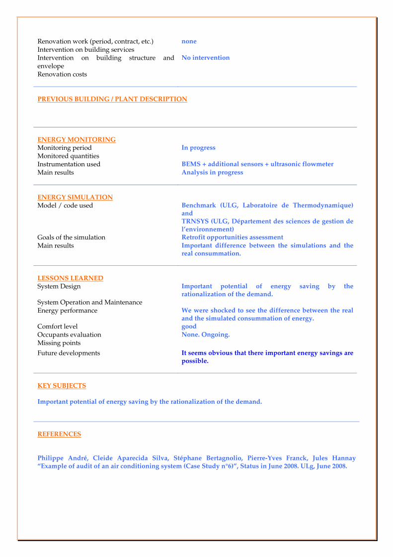
Renovation work (period, contract, etc.) none
Intervention on building services
Intervention on building structure and envelope
No intervention
Renovation costs
PREVIOUS BUILDING / PLANT DESCRIPTION
ENERGY MONITORING Monitoring period In progress
Monitored quantities
Instrumentation used BEMS + additional sensors + ultrasonic flowmeter
Main results Analysis in progress
ENERGY SIMULATION Model / code used Benchmark (ULG, Laboratoire de Thermodynamique)
and TRNSYS (ULG, Département des sciences de gestion de l’environnement)
Goals of the simulation Retrofit opportunities assessment
Main results Important difference between the simulations and the real consummation.
LESSONS LEARNED System Design Important potential of energy saving by the
rationalization of the demand. System Operation and Maintenance
Energy performance We were shocked to see the difference between the real and the simulated consummation of energy.
Comfort level good
Occupants evaluation None. Ongoing.
Missing points
Future developments It seems obvious that there important energy savings are possible.
KEY SUBJECTS Important potential of energy saving by the rationalization of the demand.
REFERENCES Philippe André, Cleide Aparecida Silva, Stéphane Bertagnolio, Pierre-Yves Franck, Jules Hannay “Example of audit of an air conditioning system (Case Study n°6)”, Status in June 2008. ULg, June 2008.

ANNEX 48: HEAT PUMPING AND REVERSIBLE AIR CONDITIONING
CASE STUDY REPORT
FRANCE case study N° 1
May 2008
ALLP building
Lyon, FRANCE
David CORGIER, INES
SITE AND CLIMATIC CONDITIONS
Location Lyon, FRANCE
Latitude; Longitude; Altitude 45°N, 8.5°E, 176 m
Mean annual temperature 12.3°C
Mean winter temperature 6°C
Winter design temperature - 9°C
Summer design temperature
Summer design daily temperature excursion
PRESENT BUILDING DESCRIPTION
Conditioned floor area 2250 m²
Conditioned building volume 8114 m3
Numbers of conditioned floors 3
Building use Offices and storage (food and oxygen)
Mean number of occupants 90
Period of construction 1974
Structure and envelope typology concrete skeleton structure consisting in posts, beams and
slabs
Occupation schedule From Monday to Friday (7 am to 19 pm)
PRESENT PLANT DESCRIPTION
Plant typology Air / water heat pump (100 kW) + Gas boiler
Heating power 100 + 350 kW
Cooling power 100 kW
Electrical power
Mechanical ventilation HVAC Air water w/2 pipes FCU
Other important plant characteristics
RETROFIT CONCEPT
Renovation work (period, contract, etc.) 6 months of work (2007 may to December)
Intervention on building services
Intervention on building structure and envelope External insulation of walls & roof, performing glazing
Renovation costs €

PREVIOUS BUILDING / PLANT DESCRIPTION
Initially, the building was equipped with a gas boiler. Comfort conditions in summer time were not acceptable
for occupants.
A first energy audit was performed to evaluate the air conditioning plant to be installed without envelope
retrofitting. The results were :
• Chiller power : 284 kW
• Estimated energy consumption :
ENERGY MONITORING
Monitoring period 3 years (minimum)
Monitored quantities 100 variables
Instrumentation used BEMS extension
Main results Energy consumption, Heat Pump efficiency and comfort
evaluation and verification
ENERGY SIMULATION
Model / code used TRNSYS 16
Goals of the simulation Materials choice and system architecture validation
Main results Heat pump sizing on the basis of cooling need
Energy consumption evaluation for economical payback
study
LESSONS LEARNED
System Design
System Operation and Maintenance
Energy performance
Comfort level
Occupants evaluation
Missing points
Future developments
KEY SUBJECTS

ANNEX 48: HEAT PUMPING AND REVERSIBLE AIR CONDITIONING
CASE STUDY REPORT
FRANCE case study N° 2
May 2008
CAUE74 building
Annecy, FRANCE
David CORGIER, INES
SITE AND CLIMATIC CONDITIONS
Location Annecy, FRANCE
Latitude; Longitude; Altitude xx°N, 8xx°E, 176 m
Mean annual temperature °C
Mean winter temperature 6°C
Winter design temperature - 9°C
Summer design temperature
Summer design daily temperature excursion
PRESENT BUILDING DESCRIPTION
Conditioned floor area 550 m²
Conditioned building volume xxxx m3
Numbers of conditioned floors 4
Building use Offices
Mean number of occupants 20
Period of construction 2008
Structure and envelope typology concrete skeleton structure consisting in posts, beams and
slabs
Occupation schedule From Monday to Friday (7 am to 19 pm)
PRESENT PLANT DESCRIPTION
Plant typology GSHP with radiant ceiling heating / cooling.
Heating power 30 kW
Cooling power 40 kW
Electrical power
Mechanical ventilation Mechanical ventilation with exhaust air heat recovery
Other important plant characteristics
RETROFIT CONCEPT
Renovation work (period, contract, etc.)
Intervention on building services

Intervention on building structure and envelope
Renovation costs
PREVIOUS BUILDING / PLANT DESCRIPTION
ENERGY MONITORING
Monitoring period 3 years (minimum)
Monitored quantities 30 variables
Instrumentation used BEMS extension
Main results Energy consumption, Heat Pump efficiency and comfort
evaluation and verification
ENERGY SIMULATION
Model / code used TRNSYS 16
Goals of the simulation Materials choice and system architecture validation
Main results Heat pump sizing on the basis of cooling need
Energy consumption evaluation for economical payback
study
LESSONS LEARNED
System Design
System Operation and Maintenance
Energy performance
Comfort level
Occupants evaluation
Missing points
Future developments
KEY SUBJECTS

ANNEX 48: HEAT PUMPING AND REVERSIBLE AIR CONDITIONING
CASE STUDY REPORT
FRANCE case study N° 3
January 2010
Heat pump prototype
for simultaneous heating and cooling
Rennes, FRANCE
Paul BYRNE, INSA Rennes
SET UP CONDITIONS
Location Laboratory of MTRheo research team,
LGCGM Rennes, FRANCE
Ambient temperature 18-23°C
Programmable controller Used for measurements and command of the plant
Temperature sensors Thermocouples type K
Hot and cold water tanks volume 300 l
Fan coil units cooling // heating power 1.5 kW 7/12°C // 3.9 kW 80/70°C
TYPE OF BUILDINGS TARGETTED
Special characteristics Simultaneous needs in heating and cooling:
Cooling + DHW production during summer
Cooling needs in rooms facing south and heating needs in
rooms facing north during spring and autumn
Building use Hotels and office buildings
Number of occupants From 30 to 100
Structure and envelope typology In conformity with French standard RT 2010
Occupation schedule All year
PRESENT PLANT DESCRIPTION
Plant typology Three modes of operation
Heating: ambient air at evaporation / water at condensation
Cooling: water at evaporation / ambient air at condensation
Simultaneous: water at evaporation / water at condensation
Heating power 15 kW
Cooling power 12 kW
Electrical power 4 kW
Other important plant characteristics Simultaneous production of heating and cooling energy
Thermosiphon defrosting technique During winter, some energy recovered by subcooling of the refrigerant
is stored at first in a cold water tank that is not used for cooling. This
energy is used subsequently as a cold source at the water evaporator in
order to improve the average coefficient of performance and to run a
thermosiphon defrosting sequence at the air evaporator.
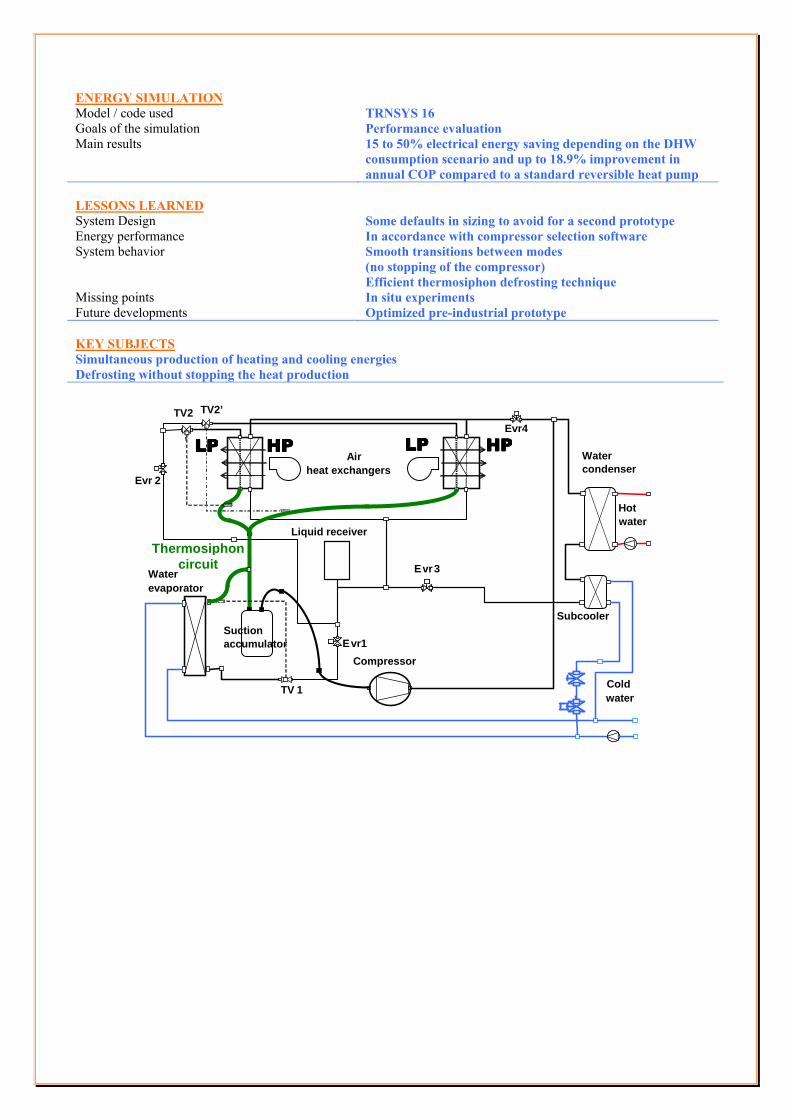
ENERGY SIMULATION
Model / code used TRNSYS 16
Goals of the simulation Performance evaluation
Main results 15 to 50% electrical energy saving depending on the DHW
consumption scenario and up to 18.9% improvement in
annual COP compared to a standard reversible heat pump
LESSONS LEARNED
System Design Some defaults in sizing to avoid for a second prototype
Energy performance In accordance with compressor selection software
System behavior Smooth transitions between modes
(no stopping of the compressor)
Efficient thermosiphon defrosting technique
Missing points In situ experiments
Future developments Optimized pre-industrial prototype
KEY SUBJECTS
Simultaneous production of heating and cooling energies
Defrosting without stopping the heat production
Compressor
Water evaporator
Air
heat exchangers
Subcooler
E vr1
TV 1
Evr 2
Water condenser
Cold water
Hot water
Suction accumulator
’ Evr4
E vr 3
TV2 TV2’
Liquid receiver
HPHPHPHP LPLPLPLP HPHPHPHP LPLPLPLP
Thermosiphon circuit
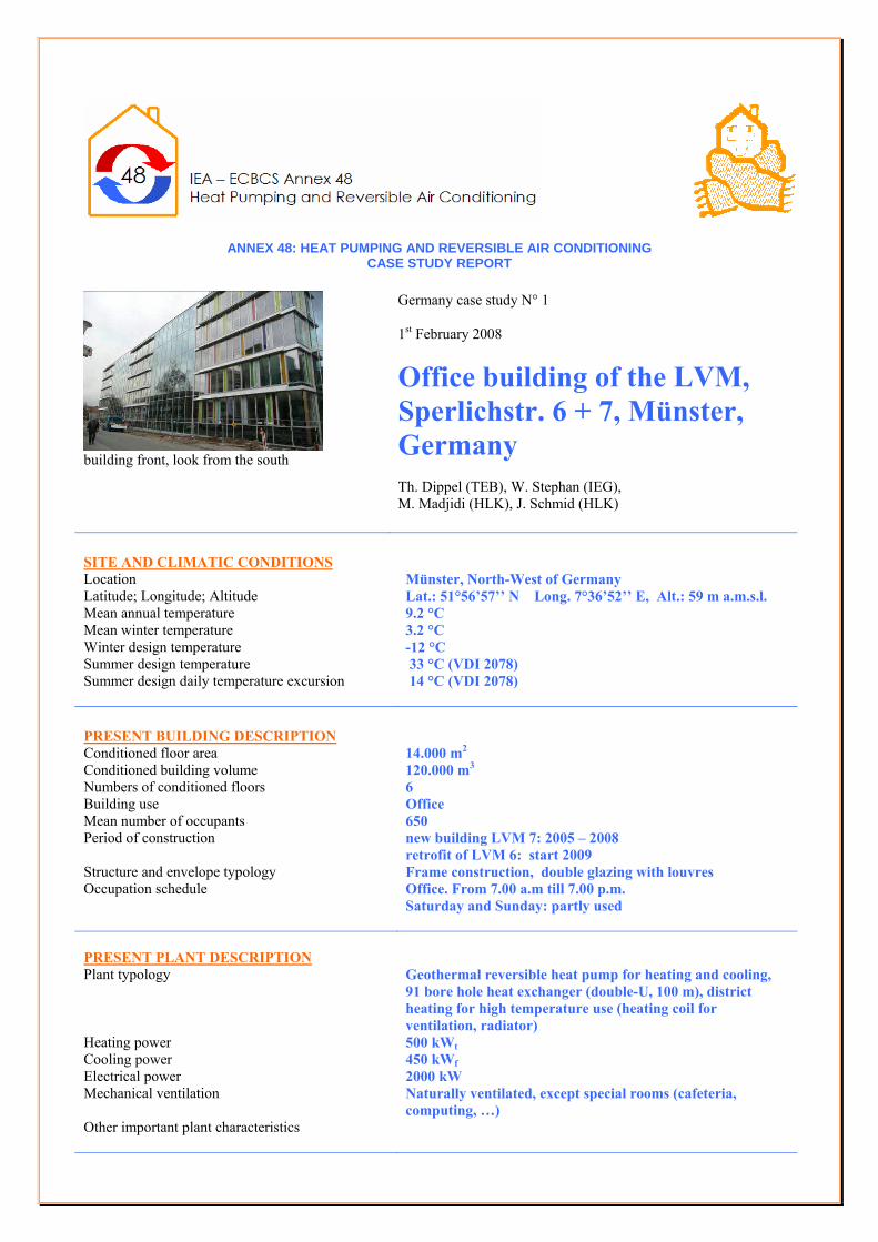
ANNEX 48: HEAT PUMPING AND REVERSIBLE AIR CONDITIONING CASE STUDY REPORT
building front, look from the south
Germany case study N° 1
1st February 2008
Office building of the LVM,
Sperlichstr. 6 + 7, Münster,
Germany
Th. Dippel (TEB), W. Stephan (IEG),
M. Madjidi (HLK), J. Schmid (HLK)
SITE AND CLIMATIC CONDITIONS
Location Münster, North-West of Germany
Latitude; Longitude; Altitude Lat.: 51°56’57’’ N Long. 7°36’52’’ E, Alt.: 59 m a.m.s.l.
Mean annual temperature 9.2 °C
Mean winter temperature 3.2 °C
Winter design temperature -12 °C
Summer design temperature 33 °C (VDI 2078)
Summer design daily temperature excursion 14 °C (VDI 2078)
PRESENT BUILDING DESCRIPTION
Conditioned floor area 14.000 m2
Conditioned building volume 120.000 m3
Numbers of conditioned floors 6
Building use Office
Mean number of occupants 650
Period of construction new building LVM 7: 2005 – 2008
retrofit of LVM 6: start 2009
Structure and envelope typology Frame construction, double glazing with louvres
Occupation schedule Office. From 7.00 a.m till 7.00 p.m.
Saturday and Sunday: partly used
PRESENT PLANT DESCRIPTION
Plant typology Geothermal reversible heat pump for heating and cooling,
91 bore hole heat exchanger (double-U, 100 m), district
heating for high temperature use (heating coil for
ventilation, radiator)
Heating power 500 kWt
Cooling power 450 kWf
Electrical power 2000 kW
Mechanical ventilation Naturally ventilated, except special rooms (cafeteria,
computing, …)
Other important plant characteristics

RETROFIT CONCEPT
Renovation work (period, contract, etc.)
Intervention on building services
Intervention on building structure and envelope
Renovation costs
PREVIOUS BUILDING / PLANT DESCRIPTION
ENERGY MONITORING
Monitoring period From 01/09/2008 to 01/09/2010
Monitored quantities Temperature, power
Instrumentation used Sensors connected to the building control system
Main results Temperatures and power consumption of: heating and
cooling system, heat pump, ground heat exchanger
ENERGY SIMULATION
Model / code used TRNSYS simulation: building, energy equipment and
ground heat exchanger, control strategy
Goals of the simulation Optimization of: thermal comfort, energy consumption
Main results Design of heat pump and size of ground heat exchanger in
relation to the building behavior
LESSONS LEARNED
System Design Seasonal efficiency of the geothermal system: ground + heat
pump.
System Operation and Maintenance
Energy performance Free cooling, simultaneous heating and cooling
Comfort level
Occupants evaluation
Missing points
Future developments
KEY SUBJECTS
Geothermal heating and cooling system, large ground loop field with 91 bore hole heat exchanger
Reversible heat pump system in a two machine cascade, free cooling, simultaneous heating and cooling
heating and cooling with concrete core activation with a new control strategy,
monitoring

ANNEX 48: HEAT PUMPING AND REVERSIBLE AIR CONDITIONING CASE STUDY REPORT
Building façade
Italy case study N° 1 December 2007 ENEA research center Brasimone, Italy M. Masoero, C.Silvi, J.Toniolo Politecnico di Torino – Dipartimento di Energetica
SITE AND CLIMATIC CONDITIONS Location Brasimone, Italy Latitude; Longitude; Altitude Lat.: 44°05’ N Long.: 11°06’ E, Alt.: 746 m a.m.s. l. Mean annual temperature 14.2 °C Mean winter temperature 5.7 °C Winter design temperature -8 °C Summer design temperature 33.0 °C (UNI 10349) Summer design daily temperature excursion 12 °C (UNI 10349) PRESENT BUILDING DESCRIPTION Conditioned floor area 300 m2 Conditioned building volume 1800 m3 Numbers of conditioned floors 2 Building use Research Institution Mean number of occupants 120 (when conference room is in use) Period of construction 1985 (refurbishment of HVAC system in 2005) Structure and envelope typology Small concrete framed building. Rectangular floor pl an.
Tilted roof (17° tilt angle) Occupation schedule Office. From 7.00 a.m till 7.00 p.m.
Saturday and Sunday: partly used PRESENT PLANT DESCRIPTION Plant typology Water-to-water reversible heat pump, using treated lake
water as the heat source / sink. Oil boiler as a ba ckup HVAC: air-water with fan coils
Heating power 68 kW t (HP) + 70 kW t (Oil boiler) Cooling power 60 kW f Electrical power 16.2 kW (max HP compressor input) Mechanical ventilation Mechanically ventilated; AHU with air-to-air heat r ecovery Other important plant characteristics BEMS monitoring and control RETROFIT CONCEPT Renovation work (period, contract, etc.) Renovation work, completed in 2005, was carried out by the
building owner Intervention on building services BEMS installation Intervention on building structure and envelope N.A. (no intervention) Renovation costs N.A.

PREVIOUS BUILDING / PLANT DESCRIPTION The original HVAC system provided just heating, wit h a 70 kW oil boiler. The existing oil boiler was m aintained for emergency use DESIGN CONCEPT Main reasons for plant selection Energy saving; Money saving; Cost/benefit balance Heating load calculation Cooling load calculation System sizing criteria ENERGY MONITORING Monitoring period From 01/04/2006 to 30/09/2006 Monitored quantities Temperature, power Instrumentation used Sensors connected to the building control system Main results Temperatures and power consumption of: heating and
cooling system, heat pump KEY SUBJECTS Reversible heat pump system Surface water heating and cooling system
SECONDARY CIRCUIT
AHU
FAN COIL
HEAT PUMP
TO LAKE
FROM LAKE
PRIMARY CIRCUIT

ANNEX 48: HEAT PUMPING AND REVERSIBLE AIR CONDITIONING CASE STUDY REPORT
Italian case study N° 1 March 2010
Regione Piemonte Headquarters Torino, Italy M. Masoero, M. Serraino, C. Silvi, J. Toniolo Politecnico di Torino – Dipartimento di Energetica
SITE AND CLIMATIC CONDITIONS Location Turin, North-West of Italy
Latitude; Longitude; Altitude Lat.: 45°07’ N; Long. 07°43’ E; Alt.: 239 m a.m.s.l.
Mean annual temperature 12.4 °C
Mean winter temperature 5.5 °C
Winter design temperature -8 °C
Summer design temperature 30.7 °C (UNI 10349)
Summer design daily temperature excursion 11 °C (UNI 10349)
PRESENT BUILDING DESCRIPTION Conditioned floor area 11.500 m2
Conditioned building volume 35.500 m3
Numbers of conditioned floors 6
Building use Office (main use), regional treasury, keeper’s lodging
Mean number of occupants 800
Period of construction 18th century façade; mostly rebuilt after WW2
Structure and envelope typology Concrete and masonry structure; not insulated walls; single glass windows
Occupation schedule Office. From 7.00 a.m till 7.00 p.m. Saturday and Sunday: closed
PRESENT PLANT DESCRIPTION Plant typology Variable refrigerant flow reversible heat pump system
with fan coils + primary air. Air cooled water chillers and condensing gas fired boilers supply hot/cold water to AHUs.
Heating power 600 kWt (VRF system); 505 kWt (condensing boiler)
Cooling power 550 kWf (VRF system); 223 kWf (water chiller)
Electrical power 259 kWe (VRF ext. units); 6 kWe (VRF ext. units); n.a. (water chiller)
Mechanical ventilation Air flow rate: 27.780 m3/h

heat recovery efficiency: 60 % Other important plant characteristics A BEMS provides complete monitoring and
management of the building services (HVAC, lighting, fire prevention, etc.)
RETROFIT CONCEPT Renovation work (period, contract, etc.) Renovation work, completed in 2002, was carried out by the
ESCO within a multi-annual energy service contract Intervention on building services Installation of a central HVAC system; lighting sys tem
retrofit; fire prevention plant reconstruction; BEM S installation
Intervention on building structure and envelope Roof modification to allow installation of chillers and external condensing / evaporating units of the HVAC system
Renovation costs n.a. PREVIOUS BUILDING / PLANT DESCRIPTION The building was originally equipped with a central hydronic heating syst em; all-air conditioning was present in limited areas; several room air conditioners of different characteristics had been installed at different times; oil-fired central boilers provi ded hot water. ENERGY MONITORING Monitoring period From 01/10/2005 to 31/09/2006
Monitored quantities VRF system electrical consumption
Instrumentation used BEMS
Main results Hourly / Daily HVAC electricity consumption 65 kWh/m2 present annual consumption
ENERGY SIMULATION Model / code used Spreadsheet
Goals of the simulation Evaluate potential energy savings associated to retrofits
Main results
LESSONS LEARNED System Design No significant problems were identified
System Operation and Maintenance BEMS output was complete and informative. Significant margins for operation improvement were identified (load management, on/off schedule, free cooling with outdoor air, etc.)
Energy performance
Comfort level No specific monitoring was performed
Occupants evaluation No specific monitoring was performed
Missing points
Future developments
KEY SUBJECTS
New plant installed in an historical building
Large-scale VRF reversible heat pump system
Detailed electricity consumption monitoring possible with BEMS
BEMS control based on actual building occupation

ANNEX 48: HEAT PUMPING AND REVERSIBLE AIR CONDITIONING CASE STUDY REPORT
Building façade, East side
Italy case study N° 3 April 2008 EIDOS office building Chieri, Italy M. Masoero, C.Silvi, J. Toniolo Politecnico di Torino – Dipartimento di Energetica
SITE AND CLIMATIC CONDITIONS Location Chieri, Piemonte, NW Italy Latitude; Longitude; Altitude Lat.: 45°04’ N Long.: 07°95’ E, Alt.: 283 m a.m.s. l. Mean annual temperature 12.3 °C Mean winter temperature 5.5 °C Winter design temperature -8 °C Summer design temperature 30.7 °C (UNI 10349) Summer design daily temperature excursion 11 °C (UNI 10349) PRESENT BUILDING DESCRIPTION Conditioned floor area 8805 m2 Conditioned building volume 22,335 m3 Numbers of conditioned floors 3 Building use Office Mean number of occupants 650 Period of construction 2006 – 2007 Structure and envelope typology Concrete columns on piling foundations; hollow-core
concrete slabs. Ventilated façade; double glazing; green roof
Occupation schedule Office. From 7.00 a.m till 7.00 p.m. Saturday and Sunday: partly used
PRESENT PLANT DESCRIPTION Plant typology Geothermal reversible heat pump for heating and coo ling,
31 borehole heat exchanger (single pipe GHX, 100 m d eep) HVAC: air-water with fan coils (storage and service areas) or active chilled beams (offices)
Heating power 94 kW t (HP) + 95-200 kW t (storage) Cooling power 137 kW f + 75-190 kW f (storage) Electrical power 28.5 kW (max HP compressor input) Mechanical ventilation Mechanically ventilated; AHU with air-to-air heat r ecovery Other important plant characteristics Hot/cold PCS (Phase-Change Storage), PCM cost 2160 €/ m 3:
- Hot storage: volume 48 m 3; thermal capacity: 950 kWh; thermal extraction rate: 95 kW (ave. 10 hrs) to 200 kW (max 4.5 hrs)
- Cold storage: volume 39 m 3; thermal capacity: 750 kWh; thermal extraction rate: 75 kW (ave. 10 hrs) to 190 kW (max 4 hrs)
Variable flow water pumps; BEMS monitoring and control

RETROFIT CONCEPT Renovation work (period, contract, etc.) N.A. (new building) Intervention on building services N.A. Intervention on building structure and envelope N.A. Renovation costs N.A. PREVIOUS BUILDING / PLANT DESCRIPTION N.A. N.A. DESIGN CONCEPT Main reasons for plant selection Energy saving; Money saving; Cost/benefit balance;
Reduction of O&M costs Heating load calculation According to Italian standard UNI 7357 Cooling load calculation According to ASHRAE Handbook methodologies System sizing criteria HP + PCS allows reduction of installed power and init ial
costs ENERGY MONITORING Monitoring period From 01/10/2007 onwards Monitored quantities Temperature, power Instrumentation used Sensors connected to the building control system Main results Temperatures and power consumption of: heating and
cooling system, heat pump, ground heat exchanger ENERGY SIMULATION Model / code used TRNSYS simulation: building, energy equipment and grou nd
heat exchanger, control strategy Goals of the simulation Optimization of: thermal comfort, energy consumptio n Main results Design of heat pumps, storage and ground heat excha nger
in relation to the building behavior LESSONS LEARNED System Design System Operation and Maintenance Energy performance Comfort level Occupants evaluation Missing points Future developments KEY SUBJECTS Reversible heat pump system hot and cold PCM storage Geothermal heating and cooling system, ground loop field with 31 bore hole heat exchanger

ANNEX 48: HEAT PUMPING AND REVERSIBLE AIR CONDITIONING CASE STUDY REPORT
Multi-purpose heat pump
Italian case study N° 4 April 2010
Santa Giulia commercial district Milano, Italy M. Masoero, C.Silvi, J. Toniolo Politecnico di Torino – Dipartimento di Energetica
SITE AND CLIMATIC CONDITIONS Location Milan, North-West of Italy
Latitude; Longitude; Altitude Lat.: 45°28’ N; Long. 09°10’ E; Alt.: 122 m a.m.s.l.
Mean annual temperature 13.7 °C
Mean winter temperature 5.2 °C
Winter design temperature -5 °C
Summer design temperature 31.9 °C (UNI 10349)
Summer design daily temperature excursion 12 °C (UNI 10349)
PRESENT BUILDING DESCRIPTION Conditioned floor area 1.500 m2
Conditioned building volume 6.000 m3
Numbers of conditioned floors 3
Building use Offices, showrooms, restaurants
Mean number of occupants n.a.
Period of construction 2004
Structure and envelope typology Concrete structure
Occupation schedule Office. From 7.00 a.m till 7.00 p.m. (Sat and Sun closed) Restaurants and showrooms: 9.30 a.m till 11.00 p.m. (Mon closed)
PRESENT PLANT DESCRIPTION Plant typology multi-purpose heat pumps (4- refrigerant pipes unit),
with fan coils + primary air. Water to water system with condenser feed by two 12 meters depth wells
Heating power 300 kWt (292 in multi-purpose mode)
Cooling power 261 kWf (209 in multi-purpose mode)
Electrical power N.A.
Other important plant characteristics A BEMS provides complete monitoring and management of the HVAC system
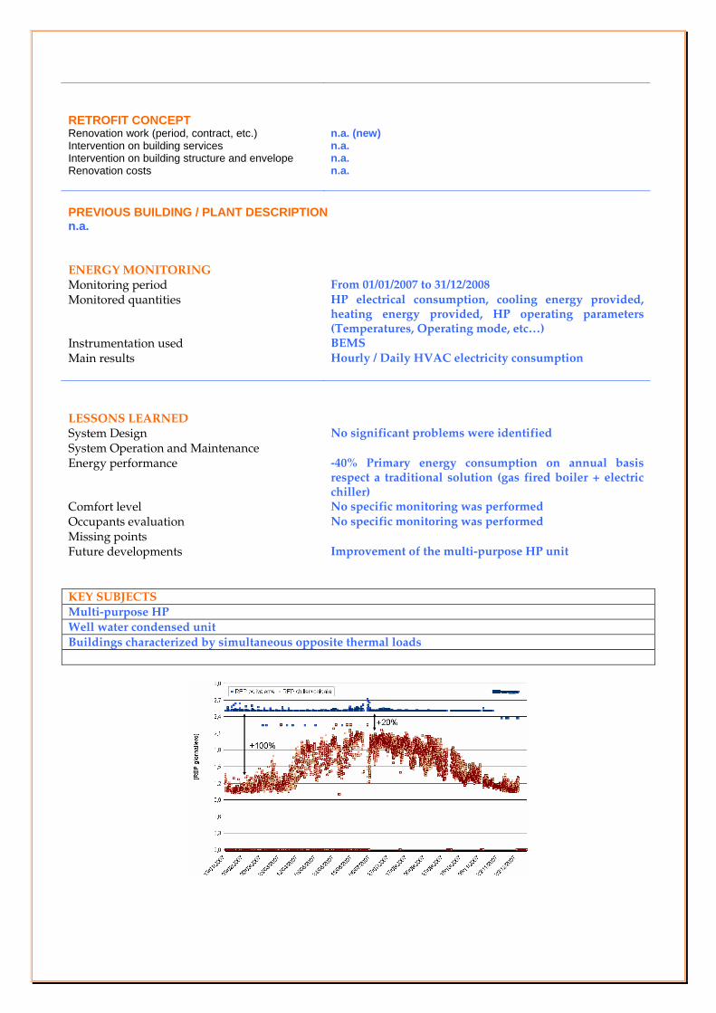
RETROFIT CONCEPT Renovation work (period, contract, etc.) n.a. (new) Intervention on building services n.a. Intervention on building structure and envelope n.a. Renovation costs n.a. PREVIOUS BUILDING / PLANT DESCRIPTION n.a. ENERGY MONITORING Monitoring period From 01/01/2007 to 31/12/2008
Monitored quantities HP electrical consumption, cooling energy provided, heating energy provided, HP operating parameters (Temperatures, Operating mode, etc…)
Instrumentation used BEMS
Main results Hourly / Daily HVAC electricity consumption
LESSONS LEARNED System Design No significant problems were identified
System Operation and Maintenance
Energy performance -40% Primary energy consumption on annual basis respect a traditional solution (gas fired boiler + electric chiller)
Comfort level No specific monitoring was performed
Occupants evaluation No specific monitoring was performed
Missing points
Future developments Improvement of the multi-purpose HP unit
KEY SUBJECTS
Multi-purpose HP
Well water condensed unit
Buildings characterized by simultaneous opposite thermal loads

ANNEX 48: HEAT PUMPING AND REVERSIBLE AIR CONDITIONING CASE STUDY REPORT
Air-Water heat pump
Italian case study N° 5 April 2010
Shopping center with water loop M. Masoero, C.Silvi, J.Toniolo Politecnico di Torino – Dipartimento di Energetica
SITE AND CLIMATIC CONDITIONS Location Caselle (Turin), North-West of Italy
Latitude; Longitude; Altitude Lat.: 45°07’ N; Long. 07°43’ E; Alt.: 239 m a.m.s.l.
Mean annual temperature 12.4 °C
Mean winter temperature 5.5 °C
Winter design temperature -8 °C
Summer design temperature 30.7 °C (UNI 10349)
Summer design daily temperature excursion 11 °C (UNI 10349)
PRESENT BUILDING DESCRIPTION Conditioned floor area 14.360 m2
Conditioned building volume 63.510 m3
Numbers of conditioned floors 2
Building use Shopping center, shops
Mean number of occupants --
Period of construction 2005
Structure and envelope typology Reinforced concrete structure; insulated walls; double glass windows
Occupation schedule Shopping centre. From 9.30 a.m till 21.00 p.m. from Monday to Saturday.
PRESENT PLANT DESCRIPTION Plant typology All air supplied by all-in-one units. Water loop and 4
pipes fan coils. Heating power supplied by gas fired boilers and heat recovery from food refrigeration.
Heating power 2508 kWt
Cooling power 2126 kWf
Electrical power
Mechanical ventilation Air flow rate: 392.040 m3/h

heat recovery efficiency: 60 % Other important plant characteristics A BEMS provides complete monitoring and
management of the building services (HVAC, lighting, fire prevention, etc.)
RETROFIT CONCEPT Renovation work (period, contract, etc.) n.a. new installation Intervention on building services n.a. Intervention on building structure and envelope n.a. Renovation costs n.a. PREVIOUS BUILDING / PLANT DESCRIPTION n.a. ENERGY MONITORING Monitoring period From 01/01/2007 to 31/12/2007
Monitored quantities Global electrical income, HVAC gas and electricity consumption
Instrumentation used BEMS
Main results Hourly / Daily HVAC electricity consumption 22% saved on HVAC electricity consumption due to installation of water loop
ENERGY SIMULATION Model / code used Spreadsheet
Goals of the simulation
Main results
LESSONS LEARNED System Design No significant problems were identified
System Operation and Maintenance Water loop improves system operation and maintenance schedule, due to the functioning stability of the whole system
Energy performance Water loop improves system efficiency, its cost has a simple payback period of 3.5 year
Comfort level No specific monitoring was performed
Occupants evaluation No specific monitoring was performed
Missing points
Future developments
KEY SUBJECTS
Water loop heat pumps
Heat pumps providing simultaneous heating and cooling