IDEC ø22mm Flush Mount CW Series Switches & Pilot Devices
24
IDEC ø22mm Flush Mount CW Series Switches & Pilot Devices
Transcript of IDEC ø22mm Flush Mount CW Series Switches & Pilot Devices

IDEC ø22mm Flush Mount CW Series Switches & Pilot Devices

Safety
Third-generation Safety Construction
Two-action removal of contact blocks
IDEC’s original two-action push-turn locking lever provides a higher level of safety by preventing unexpected release of the locking lever. In addition, the position of the locking lever can be used to verify if the contact block was installed securely by chec-ing from the back of the panel.
Locking lever integrated with guard
Prevents locking lever from unexpected release or damage by trapped wires.
IP20 Finger-safe Terminals
Finger-safe, IP20 terminals prevent electrical shock.
Bezel Black or metallic
Illuminated Pushbuttons - Page 6• Round flush and extended• Illumination colors: amber, blue,
green, white, red, yellow
Non-illuminated Pushbuttons - Page 8• Round flush and extended• Button colors: black, blue, green,
red, yellow, white
Pilot Lights - Page 9• Round flush and extended• Illumination colors: amber, blue,
green, white, red, yellow
Safety, Style and Flexibility
kTurn Guard
j Push
2
800.262.4332www.IDEC.com/switches
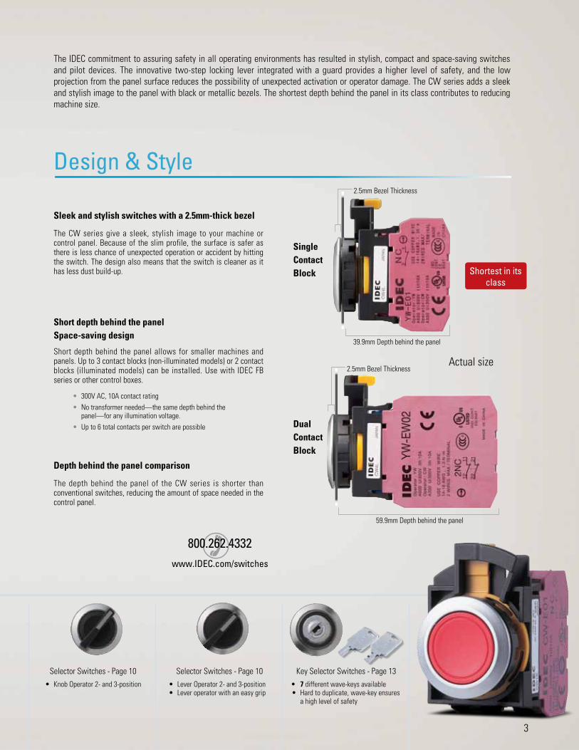
Safety, Style and FlexibilityThe IDEC commitment to assuring safety in all operating environments has resulted in stylish, compact and space-saving switches and pilot devices. The innovative two-step locking lever integrated with a guard provides a higher level of safety, and the low projection from the panel surface reduces the possibility of unexpected activation or operator damage. The CW series adds a sleek and stylish image to the panel with black or metallic bezels. The shortest depth behind the panel in its class contributes to reducing machine size.
Design & Style
Sleek and stylish switches with a 2.5mm-thick bezel
The CW series give a sleek, stylish image to your machine or control panel. Because of the slim profile, the surface is safer as there is less chance of unexpected operation or accident by hitting the switch. The design also means that the switch is cleaner as it has less dust build-up.
Actual size
Short depth behind the panel Space-saving design
Short depth behind the panel allows for smaller machines and panels. Up to 3 contact blocks (non-illuminated models) or 2 contact blocks (illuminated models) can be installed. Use with IDEC FB series or other control boxes.
• 300V AC, 10A contact rating• No transformer needed—the same depth behind the
panel—for any illumination voltage. • Up to 6 total contacts per switch are possible
Selector Switches - Page 10 Selector Switches - Page 10• Knob Operator 2- and 3-position • Lever Operator 2- and 3-position
• Lever operator with an easy grip
Shortest in its class
Key Selector Switches - Page 13• 7 different wave-keys available• Hard to duplicate, wave-key ensures
a high level of safety
2.5mm Bezel Thickness
39.9mm Depth behind the panel
The depth behind the panel of the CW series is shorter than conventional switches, reducing the amount of space needed in the control panel.
Depth behind the panel comparison
2.5mm Bezel Thickness
59.9mm Depth behind the panel
Single Contact Block
Dual Contact Block
3

Flush bezel projects only 2.5mm from front of panel and as little as 39.9mm behind the panel!
• ø22.3mm mounting hole compliant with IEC 60947-5-1• 3.5mm operator travel for pushbuttons ensures comfortable and reliable
operation• Up to 6 contacts per switch are possible with use of dual contact blocks• Black and metallic bezels available• Illuminated pushbuttons, pushbuttons, pilot lights, selector switches and key
selector switches are available• Direct opening NC contact • Seven different keys can be chosen for key selector switches• 10A contact rating; up to three contact blocks for non-illuminated and two
contact blocks for illuminated models can be connected• Contact blocks can be removed by using the locking lever• IP20 finger-safe screw terminals• UL Type 4X rating Applicable Standards Mark File No. or Organization
UL508CSA C22.2 No.14 UL/c-UL File No. E68961
EN60947-5-1TÜV SÜD
EC Low Voltage Directive
Contact RatingsRated Insulation Voltage (Ui) 300V
Rated Thermal Current (Ith) 10A
Rated Operating Voltage (Ue) 24V 120V 240V
Rated Operating Current (Ie)
Electrical Life 50,000 operations
AC 50/60 Hz
Resistive Load (AC-12) 10A 10A 6A
Inductive Load (AC-15) 10A 6A 3A
DC
Resistive Load (DC-12) 8A 2.2A 1.1A
Inductive Load (DC-13) 4A 1.1A 0.55A
Electrical Life 100,000 operations
AC 50/60 Hz
Resistive Load (AC-12) 5A 5A 3A
Inductive Load (AC-15) 5A 3A 1.5A
DC
Resistive Load (DC-12) 4A 1.1A 0.55A
Inductive Load (DC-13) 2A 0.55A 0.27A
Contact Material Silver
1. Minimum applicable load (reference value): 3V AC/DC, 5 mA (Applicable range is subject to the operating conditions and load.)
2. The operational current represents the classification by making and breaking currents (IEC 60947-5-1).
3. UL, c-UL rating: A300
Weights
Illuminated Pushbutton 46g (CW1L-M1E02QH, 2 contacts)62g (CW1L-M1E22QH, 4 contacts)
Pushbutton 45g (CW1B-M1E03, 3 contacts)52g (CW1B-M1E22, 4 contacts)
Pilot Light 27g (CW1P-1EQH)
Selector Switch 48g (CW1S-2E03, 3 contacts)55g (CW1S-2E22, 4 contacts)
Key Selector Switch 61g (CW1K-2AE03, 3 contacts)68g (CW1K-2AE22, 4 contacts)
Specifications
Operating Temperature Non-illuminated: –25 to +60°C (no freezing)LED illuminated: –25 to +55°C (no freezing)
Operating Humidity 45 to 85% RH (no condensation)
Storage Temperature –40 to +80°C
Contact Resistance 50 mΩ maximum (initial value)Insulation Resistance 100 MΩ minimum (500V DC megger)Overvoltage Category II (IEC 60664-1)Impulse Withstand Voltage 2.5 kV (IEC60664-1/60947-5-1)
Pollution Degree 3 (IEC60947-5-1)Vibration Resistance Operating extremes: 5 to 55Hz, amplitude 0.5 mm
Shock Resistance Operating extremes: 100 m/s2
Damage limits: 1000 m/s2
Mechanical Life(minimum operations)
Pushbutton, illuminated pushbutton: 2,000,000Selector switch: 250,000Key selector switch: 250,000
Electrical Life(minimum operations)
50,000 (see Contact Ratings)100,000 (see Contact Ratings)(switching frequency 1800 operations/h)
Degree of Protection (IEC60529)
Panel front: IP65, IP66, IP67 (see chart on page 5)Terminals: IP20Type 4X
Short-circuit Protection 250V/10A fuse, (Type aM IEC60269-1, IEC602069-2)Electrical Shock Protection Class II (IEC61140)
Terminal Style Screw terminal (M3.5 slotted Phillips screw)Bezel Material Polyamide
Applicable Wire SizeUp to 2 wires of 2 mm2 (solid wire ø1.6) maximum (AWG14 to 16) (Ring terminal cannot be used)
Recommended Tightening Torque
Terminal: 1.0 to 1.3 N·mLocking ring: 1.2 N·m
Direct Opening of Key Selector Switch 2-position (3NC) 3-position (2NC)
Operator Angle for Direct Opening Action 90° 45°Minimum Operator Torque for Direct Opening Action 0.2 N·m 0.3 N·m
Maximum Operator Angle 90° 45°
4
ø22mm Flush Mount CW Switches & Pilot Devices
4

800.262.4332www.IDEC.com/switches
LED ModuleRated Insulation Voltage (Ui) 250V
Rated Operating Voltage (Ue) 6V AC/DC 12V AC/DC 24V AC/DC 100/120V AC 230/240V AC
Operating Voltage Range 6V AC/DC±10% 12V AC/DC±10% 24V AC/DC±10% 100/120V AC±10% 230/240V AC +/-10%Illumination Color Code k A (amber), G (green), PW (white), R (red), S (blue)LED Module Part Number CW-EAQ2k CW-EAQ3k CW-EAQ4k CW-EAQHk CW-EAQM4kCurrent Draw 15 mA 15 mA 16.5 mA 18 mA 18 mALife (reference value) Approx. 30,000 hours
Internal CircuitZener DiodeResistor
Rectifying Diode
LED Chip
R
R
X2
X1
CapacitorC
R
X1
X2
R
R
LED ChipRectifying Diode
ResistorZener Diode
1. Specify an illumination color code in place of k in the part number.2. Use the white (PW) LED module for yellow illumination.
Note: Determine mounting centers to ensure proper spacing.
Mounting Hole Layout
IEC 60947-5-1 compliant
R0.8 max.
0+0.4
+0.4
0
+0.20
30
50
ø22.3
3.2
24.1
Contact BlocksContact Block Single Contact Block Double Contact Block
Contact 1NO 1NC 2NO 2NC 1NO-1NC
Part No. YW-E10R YW-E01 YW-EW2R0 YW-EW02 YW-EW1R1
Shape
Housing Color Blue/Black Reddish Purple Blue/Black Reddish Purple Reddish Purple/Blue
Push Rod Color Black Red Black Red Gray
Terminal No. 3-4 1-2 1st tier: 13-142nd tier: 23-24
1st tier: 11-122nd tier: 21-22
1st tier: (NO) 13-142nd tier: (NC) 21-22
Weight (approx.) 11g 19g
Degree of ProtectionRating IP65 IP66 IP67 UL Type 4X
Illuminated Pushbutton Yes Yes * Yes * Yes *
Pilot Light Yes Yes No Yes
Pushbutton Yes Yes * Yes * Yes *
Selector Switch Yes Yes Yes Yes
Key Selector Switch Yes Yes No Yes
*When used with rubber boot (CW9Z-D11, -D12)
5

Illuminated Pushbuttons (Assembled)
Shape Operating Voltage
Contact Configuration Black Bezel Metallic Bezel Illumination Color
Code k
Round FlushCW0L-01
(black bezel)
(metallic bezel)
6V AC/DC
1NO1NC
1NO-1NC2NO2NC
2NO-2NC
CW1L-1E10Q2kCW1L-1E01Q2kCW1L-1E11Q2kCW1L-1E20Q2kCW1L-1E02Q2kCW1L-1E22Q2k
CW4L-1E10Q2kCW4L-1E01Q2kCW4L-1E11Q2kCW4L-1E20Q2kCW4L-1E02Q2kCW4L-1E22Q2k
A: amberG: greenPW: whiteR: redS: blue Y: yellow
12V AC/DC
1NO1NC
1NO-1NC2NO2NC
2NO-2NC
CW1L-1E10Q3kCW1L-1E01Q3kCW1L-1E11Q3kCW1L-1E20Q3kCW1L-1E02Q3kCW1L-1E22Q3k
CW4L-1E10Q3kCW4L-1E01Q3kCW4L-1E11Q3kCW4L-1E20Q3kCW4L-1E02Q3kCW4L-1E22Q3k
24V AC/DC
1NO1NC
1NO-1NC2NO2NC
2NO-2NC
CW1L-1E10Q4kCW1L-1E01Q4kCW1L-1E11Q4kCW1L-1E20Q4kCW1L-1E02Q4kCW1L-1E22Q4k
CW4L-1E10Q4kCW4L-1E01Q4kCW4L-1E11Q4kCW4L-1E20Q4kCW4L-1E02Q4kCW4L-1E22Q4k
100/120V AC
1NO1NC
1NO-1NC2NO2NC
2NO-2NC
CW1L-1E10QHkCW1L-1E01QHkCW1L-1E11QHkCW1L-1E20QHkCW1L-1E02QHkCW1L-1E22QHk
CW4L-1E10QHkCW4L-1E01QHkCW4L-1E11QHkCW4L-1E20QHkCW4L-1E02QHkCW4L-1E22QHk
230/240V AC
1NO1NC
1NO-1NC2NO2NC
2NO-2NC
CW1L-1E10QM4kCW1L-1E01QM4kCW1L-1E11QM4kCW1L-1E20QM4kCW1L-1E02QM4kCW1L-1E22QM4k
CW4L-1E10QM4kCW4L-1E01QM4kCW4L-1E11QM4kCW4L-1E20QM4kCW4L-1E02QM4kCW4L-1E22QM4k
Round ExtendedCW0L-02
(black bezel)
(metallic bezel)
6V AC/DC
1NO1NC
1NO-1NC2NO2NC
2NO-2NC
CW1L-2E10Q2kCW1L-2E01Q2kCW1L-2E11Q2kCW1L-2E20Q2kCW1L-2E02Q2kCW1L-2E22Q2k
CW4L-2E10Q2kCW4L-2E01Q2kCW4L-2E11Q2kCW4L-2E20Q2kCW4L-2E02Q2kCW4L-2E22Q2k
A: amberG: greenPW: whiteR: redS: blueY: yellow
12V AC/DC
1NO1NC
1NO-1NC2NO2NC
2NO-2NC
CW1L-2E10Q3kCW1L-2E01Q3kCW1L-2E11Q3kCW1L-2E20Q3kCW1L-2E02Q3k CW1L-2E22Q3k
CW4L-2E10Q3kCW4L-2E01Q3kCW4L-2E11Q3kCW4L-2E20Q3kCW4L-2E02Q3kCW4L-2E22Q3k
24V AC/DC
1NO1NC
1NO-1NC2NO2NC
2NO-2NC
CW1L-2E10Q4kCW1L-2E01Q4kCW1L-2E11Q4kCW1L-2E20Q4kCW1L-2E02Q4kCW1L-2E22Q4k
CW4L-2E10Q4kCW4L-2E01Q4kCW4L-2E11Q4kCW4L-2E20Q4kCW4L-2E02Q4kCW4L-2E22Q4k
100/120V AC
1NO1NC
1NO-1NC2NO2NC
2NO-2NC
CW1L-2E10QHkCW1L-2E01QHkCW1L-2E11QHkCW1L-2E20QHkCW1L-2E02QHkCW1L-2E22QHk
CW4L-2E10QHkCW4L-2E01QHkCW4L-2E11QHkCW4L-2E20QHkCW4L-2E02QHkCW4L-2E22QHk
230/240V AC
1NO1NC
1NO-1NC2NO2NC
2NO-2NC
CW1L-2E10QM4kCW1L-2E01QM4kCW1L-2E11QM4kCW1L-2E20QM4kCW1L-2E02QM4kCW1L-2E22QM4k
CW4L-2E10QM4kCW4L-2E01QM4kCW4L-2E11QM4kCW4L-2E20QM4kCW4L-2E02QM4kCW4L-2E22QM4k
1. Specify an illumination color code in place of k in the Part Number2. Specify function code in place of in the Part Number. M: momentary, A: maintained3. See page page 16 for dimensions.4. See next page for replacement LED modules.5. A dummy block is installed when one contact block is used.6. Additional contact configurations available, contact IDEC for more details.
Illuminated Pushbuttons
6

800.262.4332www.IDEC.com/switches
Illuminated Pushbuttons (Sub-assembled)
Contact Block LED Module Mounting Adaptor Operator Lens Completed Unit
+ + + + =
Contact Block
Style Contacts Contact Block
Contact Configuration
Part Number
Finger-safe Screw terminal
Single1NO YW-E10R
1NC YW-E01
Double
2NO YW-EW2R0
2NC YW-EW02
1N0-1NC YW-EW1R1
Dummy block CW-DB
LED Module
Style Part Number
CW-EAQ kj
1. In place of j, specify the Lens/LED Color Code from table.2. In place of k, specify the Voltage Code from table.
Contact Block Mounting Adaptor
Style Part Number
CW-CN
Operator
Style Black Bezel Metallic Bezel
Momentary
Round flush CW1B-M10 CW4B-M10
Round extended CW1B-M20 CW4B-M20
Maintained
Round flush CW1B-A10 CW4B-A10
Round extended CW1B-A20 CW4B-A20
Lens
Style Part number
Round flush CW9Z-L11j
Round extended CW9Z-L12j
1. In place of j, specify the Lens/LED Color Code from table.
j Lens/LED Color Code
Color Code
Amber A
Green G
Red R
Blue S
White* PW or C
Yellow Y
*Use PW for LED module, use C for lens.
k Voltage Code
Voltage Code
6V AC/DC 2
12V AC/DC 3
24V AC/DC 4
100/120V AC H
230/240V AC M4
Illuminated Pushbuttons
7

800.262.4332www.IDEC.com/switches
Non-illuminated Pushbuttons (Assembled)
Shape Contact Configuration Black Bezel Metallic Bezel Button Color Code j
Round FlushCW0B-01
(black bezel)
1NO1NC
1NO-1NC2NO2NC
2NO-1NC*1NO-2NC*
3NO*3NC*
2NO-2NC
CW1B-1E10jCW1B-1E01jCW1B-1E11jCW1B-1E20jCW1B-1E02jCW1B-M1E21jCW1B-M1E12jCW1B-M1E30jCW1B-M1E03jCW1B-1E22j
CW4B-1E10jCW4B-1E01jCW4B-1E11jCW4B-1E20jCW4B-1E02jCW4B-M1E21jCW4B-M1E12jCW4B-M1E30jCW4B-M1E03jCW4B-1E22j
B: blackG: greenR: redS: blueW: whiteY: yellow
Round ExtendedCW0B-02
(metallic bezel)
1NO1NC
1NO-1NC2NO2NC
2NO-1NC*1NO-2NC*
3NO*3NC*
2NO-2NC
CW1B-2E10jCW1B-2E01jCW1B-2E11jCW1B-2E20jCW1B-2E02jCW1B-M2E21jCW1B-M2E12jCW1B-M2E30jCW1B-M2E03jCW1B-2E22j
CW4B-2E10jCW4B-2E01jCW4B-2E11jCW4B-2E20jCW4B-2E02jCW4B-M2E21jCW4B-M2E12jCW4B-M2E30jCW4B-M2E03jCW4B-2E22j
1. Specify a button color code in place of j in the part number.2. Specify function code in place of in the Part Number. M: momentary, A: maintained3. See page page 17 for dimensions.4. Two or one dummy block is installed when one or two contact blocks are used, respectively.5. *These contact configurations are not available in maintained action.6. Additional contact configurations available; contact IDEC for more details.
Non-illuminated Pushbuttons (Sub-assembled)
Contact Block Mounting Adaptor Operator* Completed Unit
+ + =
Contact Block
Style Contacts Contact Block
Contact Configuration
Part Number
Finger-safe Screw terminal
Single1NO YW-E10R
1NC YW-E01
Double
2NO YW-EW2R0
2NC YW-EW02
1N0-1NC YW-EW1R1
Dummy block CW-DB
Contact Block Mounting Adaptor
Style Part Number
CW-CN
j Button Color Code
Color Code
Black B
Green G
Red R
Blue S
White W
Yellow Y
Operator*
Style Black Bezel
Metallic Bezel
Mom
enta
ry Roun
d flu
sh CW1B-M1j CW4B-M1j
Roun
d ex
tend
ed
CW1B-M2j CW4B-M2j
Mai
ntai
ned
Roun
d flu
sh CW1B-A1j CW4B-A1j
Roun
d ex
tend
ed
CW1B-A2j CW4B-A2j
1. Specify a button color code in place of j.2. *Operator button is not removable from operator.
Non-illuminated Pushbuttons
8

Pilot Lights (Assembled)
Shape Operating Voltage Black Bezel Metallic Bezel Illumination Color Code k
Round Flush LensCW0P-1
(black bezel)
6V AC/DC CW1P-1EQ2k CW4P-1EQ2k
A: amberG: greenR: redS: bluePW: white Y: yellow
12V AC/DC CW1P-1EQ3k CW4P-1EQ3k
24V AC/DC CW1P-1EQ4k CW4P-1EQ4k
100/120V AC CW1P-1EQHk CW4P-1EQHk
230/240V AC CW1P-1EQM4k CW4P-1EQM4k
Round Dome LensCW0P-2
(metallic bezel)
6V AC/DC CW1P-2EQ2k CW4P-2EQ2k
12V AC/DC CW1P-2EQ3k CW4P-2EQ3k
24V AC/DC CW1P-2EQ4k CW4P-2EQ4k
100/120V AC CW1P-2EQHk CW4P-2EQHk
230/240V AC CW1P-2EQM4k CW4P-2EQM4k
1. Specify an illumination color code in place of k in the Part Number2. See page page 17 for dimensions.3. See page page 21 for replacement LED modules.4. Two dummy blocks are installed.
Pilot Lights (Sub-assembled)
Contact Block* LED Module Mounting Adaptor Operator Lens Completed Unit
+ + + + =
*2 dummy blocks are required for each completed pilot light.
Contact Block
Style Part Number
Dummy block CW-DB
LED Module
Style Part Number
CW-EAQ kj
1. In place of j, specify the Lens/LED Color Code from table.
2. In place of k, specify the Voltage Code from table.
Contact Block Mounting Adaptor
Style Part Number
CW-CN
Operator
Style Black Bezel
Metallic Bezel
CW1P-00 CW4P-00
Lens
Style Part Number
Round flush CW9Z-L11j
Round dome CW9Z-L15j
1. In place of j, specify the Lens/LED Color Code from table.
j Lens/LED Color Code
Color Code
Amber A
Green G
Red R
Blue S
White* PW or C
Yellow Y
* Use PW for LED module, use C for lens.
k Voltage Code
Voltage Code
6V AC/DC 2
12V AC/DC 3
24V AC/DC 4
100/120V AC H
230/240V AC M4
Pilot Lights
9

800.262.4332www.IDEC.com/switches
Shape
CW0S (Knob Operator)
No. of PositionsContact
Configuration(Code)
Contact Block Operator Position L R
Maintained
L R
Spring return from right
Mounting Position Contact L R
90° 2-position
1NO (10)
1 NOCW0S-2E10 CW0S-21E102 — Dummy
3 — Dummy
1NC (01)
1 — DummyCW0S-2E01 CW0S-21E012 — Dummy
3 NC
1NO-1NC (11)
1 NOCW0S-2E11 CW0S-21E112 — Dummy
3 NC
2NO (20)
1 NOCW0S-2E20 CW0S-21E202 — Dummy
3 NO
2NC (02)
1 NCCW0S-2E02 CW0S-21E022 — Dummy
3 NC
2NO-1NC (21)
1 NOCW0S-2E21 CW0S-21E212 NO
3 NC
1NO-2NC (12)
1 NOCW0S-2E12 CW0S-21E122 NC
3 NC
3NO (30)
1 NOCW0S-2E30 CW0S-21E302 NO
3 NO
3NC (03)
1 NCCW0S-2E03 CW0S-21E032 NC
3 NC
2NO-2NC (22)
1 NO/NC
NO
CW0S-2E22 CW0S-21E22NC
2 — Dummy
3 NO/NC
NONC
4NO (40)
1 2NONO
CW0S-21E40 CW0S-21E40NO
2 — Dummy
3 2NONONO
1. Specify a bezel color code in place of 0 in the part number: 1 (black bezel), 4 (metallic bezel).2. Lever operator is also available. For dimensions, see page page 18.3. To order a lever operator selector switch, insert L before E in the knob operator part number.Example: Knob Operator part number CW1S-2E10 becomes CW1S-2LE10 for Lever Operator.
Selector Switches (Assembled)
(metallic bezel)(black bezel)
CW1S-0L (black bezel)
Contact Block Mounting Position
CW4S-0L (metallic bezel)
Lever Operator
Left Center Right
L C R1 NO2 NC3 NC
Operator Position
1 2 3
Selector Switches
10

800.262.4332www.IDEC.com/switches
No. of Positions
Contact Configuration
(Code)
Contact Block Operator Position CL R
Maintained
CL R
Spring return from right
CL R
Spring return from left
CL R
Spring return two-way
Mounting Position Type L C R
45° 3-position
1NO-1NC (11)
1 NOCW0S-3E11 CW0S-31E11 CW0S-32E11 CW0S-33E112 — Dummy
3 NC
1NO-1NC (11N1)
1 NCCW0S-3E11N1 CW0S-31E11N1 CW0S-32E11N1 CW0S-33E11N12 — Dummy
3 NO
1NO-1NC (11N2)
1 NOCW0S-3E11N2 CW0S-31E11N2 CW0S-32E11N2 CW0S-33E11N22 NC
3 — Dummy
1NO-1NC (11N3)
1 — DummyCW0S-3E11N3 CW0S-31E11N3 CW0S-32E11N3 CW0S-33E11N32 NC
3 NO
1NO-1NC (11N4)
1 — DummyCW0S-3E11N4 CW0S-31E11N4 CW0S-32E11N4 CW0S-33E11N42 NO
3 NC
2NO (20)
1 NOCW0S-3E20 CW0S-31E20 CW0S-32E20 CW0S-33E202 — Dummy
3 NO
2NO (20N1)
1 — DummyCW0S-3E20N1 CW0S-31E20N1 CW0S-32E20N1 CW0S-33E20N12 NO
3 NO
2NC (02)
1 NCCW0S-3E02 CW0S-31E02 CW0S-32E02 CW0S-33E02
1. Specify a bezel color code in place of 0 in the Part Number, 1 (black bezel), 4 (metallic bezel)
2. For the contact block mounting position, see page 10.
3. Lever operator is also available. For dimensions, see page page 18.
4. To order a lever operator selector switch, insert L before E in the knob operator part number.
Example: Knob Operator part number CW1S-3E11 becomes CW1S-3LE11 for Lever Operator.
2 — Dummy3 NC
2NC (02N1)
1 — DummyCW0S-3E02N1 CW0S-31E02N1 CW0S-32E02N1 CW0S-33E02N12 NC
3 NC
2NO-1NC (21)
1 NOCW0S-3E21 CW0S-31E21 CW0S-32E21 CW0S-33E212 NO
3 NC
2NO-1NC (21N1)
1 NOCW0S-3E21N1 CW0S-31E21N1 CW0S-32E21N1 CW0S-33E21N12 NC
3 NO
1NO-2NC (12)
1 NOCW0S-3E12 CW0S-31E12 CW0S-32E12 CW0S-33E122 NC
3 NC
1NO-2NC (12N1)
1 NCCW0S-3E12N1 CW0S-31E12N1 CW0S-32E12N1 CW0S-33E12N12 NO
3 NC
3NO (30)
1 NOCW0S-3E30 CW0S-31E30 CW0S-32E30 CW0S-33E302 NO
3 NO
3NC (03)
1 NCCW0S-3E03 CW0S-31E03 CW0S-32E03 CW0S-33E032 NC
3 NC
2NO-2NC (22)
1 NO/NC
NO
CW0S-3E22 CW0S-31E22 CW0S-32E22 CW0S-33E22NC
2 — Dummy
3 NO/NC
NONC
4NO (40)
1 2NONO
CW0S-3E40 CW0S-31E40 CW0S-32E40 CW0S-33E40NO
2 — Dummy
3 2NONONO
2NO-2NC (22N2)
1 2NCNC
CW0S-3E22N2 CW0S-31E22N2 CW0S-32E22N2 CW0S-33E22N2NC
2 — Dummy
3 2NONCNC
Selector Switches
11

800.262.4332www.IDEC.com/switches
Selector Switches (Sub-assembled)
Contact Block Mounting Adaptor Operator Completed Unit
+ + =
Contact Block
Style Contacts Contact Block
Contact Configuration
Part Number
Finger-safe Screw terminal
Single1NO YW-E10R
1NC YW-E01
Double
2NO YW-EW2R0
2NC YW-EW02
1N0-1NC YW-EW1R1
Dummy block CW-DB
Contact Block Mounting Adaptor
Style Part Number
CW-CN
Operator
Style Position Handle Description Black Bezel Metallic Bezel
(knob operator shown)
2 position
KnobMaintained CW1S-2 CW4S-2
Spring return from right CW1S-21 CW4S-21
Lever Maintained CW1S-2L CW4S-2L
Spring return from right CW1S-21L CW4S-21L
3 position
Knob
Maintained CW1S-3 CW4S-3
Spring return from right CW1S-31 CW4S-31
Spring return from left CW1S-32 CW4S-32
Spring return two-way CW1S-33 CW4S-33
Lever
Maintained CW1S-3L CW4S-3L
Spring return from right CW1S-31L CW4S-31L
Spring return from left CW1S-32L CW4S-32L
Spring return two-way CW1S-33L CW4S-33L
Lever or knob is supplied with operator
Selector Switches
12

Shape
CW0K
No. of Positions Contact Configuration
Contact Block Operator Position L R
Maintained
L R
Spring return from right
Mounting Position Type L R
90° 2-position
1NO (10)
1 NOCW0K-2AE10 CW0K-21BE102 — Dummy
3 — Dummy
1NC (01)
1 — DummyCW0K-2AE01 CW0K-21BE012 — Dummy
3 NC
1NO-1NC (11)
1 NOCW0K-2AE11 CW0K-21BE112 — Dummy
3 NC
2NO (20)
1 NOCW0K-2AE20 CW0K-21BE202 — Dummy
3 NO
2NC (02)
1 NCCW0K-2AE02 CW0K-21BE022 — Dummy
3 NC
2NO-1NC (21)
1 NOCW0K-2AE21 CW0K-21BE212 NO
3 NC
1NO-2NC (12)
1 NOCW0K-2AE12 CW0K-21BE122 NC
3 NC
3NO (30)
1 NOCW0K-2AE30 CW0K-21BE302 NO
3 NO
3NC (03)
1 NCCW0K-2AE03 CW0K-21BE032 NC
3 NC
2NO-2NC (22)
1 NO/NCNO
CW0K-2AE22 CW0K-21BE22NC
2 — Dummy
3 NO/NCNONC
4NO (40)
1 2NONO
CW0K-2AE40 CW0K-21BE40NO
2 — Dummy
3 2NONONO
1. Specify a bezel color code in place of 0 in the Part Number: 1 (black bezel), 4 (metallic bezel).
2. On the spring-returned models, the key can be released only from the maintained position. On the maintained models, the key can be released from any position. Key retained positions are also available. See below.
3. Two keys are supplied.4. Key cylinder material: Metal
5. Besides the standard key (key number 0H), six other keys are also available. See below.
6. For the contact block mounting position, see page 14.7. For dimensions, see page page 19.8. When ordering an optional key or optional key retained positions, specify
designation codes as shown below:
Key removal position code2-position
A: Removable in all positions B: Removable in left only C: Removable in right only
3-position A: Removable in all positions B: Removable in left and center C: Removable in right and center D: Removable in center only E: Removable in right and left G: Removable in left only H: Removable in right only
blank): Standard key (0H, reversible)1H to 2H: Reversible key3H to 6H: Non-reversible keyy
Note: Key number is indicated on the key cylinder. Standard keys do not have a key number indication.
Example: CW1K-2AE10-1H
Key Selector Switches (Assembled)
(metallic bezel)(black bezel)
Key Selector Switches
13

No. of Positions
Contact Configuration
Contact Block Operator Position
CL R
Maintained
CL R
Spring return from right
CL R
Spring return from left
CL R
Spring return two-way
Mounting Position Type L C R
45° 3-position
1NO-1NC (11)
1 NOCW0K-3AE11 CW0K-31BE11 CW0K-32CE11 CW0K-33DE112 — Dummy
3 NC
1NO-1NC (11N1)
1 NCCW0K-3AE11N1 CW0K-31BE11N1 CW0K-32CE11N1 CW0K-33DE11N1
Mounting Position
1 2 3
Left Center Right
OperatorPosition
L C R
1 NO2 NC3 NC
2 — Dummy3 NO
1NO-1NC (11N2)
1 NOCW0K-3AE11N2 CW0K-31BE11N2 CW0K-32CE11N2 CW0K-33DE11N22 NC
3 — Dummy
1NO-1NC (11N3)
1 — DummyCW0K-3AE11N3 CW0K-31BE11N3 CW0K-32CE11N3 CW0K-33DE11N32 NC
3 NO
1NO-1NC (11N4)
1 — DummyCW0K-3AE11N4 CW0K-31BE11N4 CW0K-32CE11N4 CW0K-33DE11N42 NO
3 NC
2NO (20)
1 NOCW0K-3AE20 CW0K-31BE20 CW0K-32CE20 CW0K-33DE202 — Dummy
3 NO
2NO (20N1)
1 — DummyCW0K-3AE20N1 CW0K-31BE20N1 CW0K-32CE20N12 NO
3 NO
2NC (02)
1 NCCW0K-3AE02 CW0K-31BE02 CW0K-32CE022 — Dummy
3 NC
2NC (02N1)
1 — DummyCW0K-3AE02N1 CW0K-31BE02N1 CW0K-32CE02N12 NC
3 NC
2NO-1NC (21)
1 NOCW0K-3AE21 CW0K-31BE21 CW0K-32CE212 NO
3 NC
2NO-1NC (21N1)
1 NOCW0K-3AE21N1 CW0K-31BE21N1 CW0K-32CE21N12 NC
3 NO
1NO-2NC (12)
1 NOCW0K-3AE12 CW0K-31BE12 CW0K-32CE12
1. Specify a bezel color code in place of 0 in the Type No.: 1 (black bezel), 4 (metallic bezel)
2. On the spring-returned types, the key can be released only from the maintained position. On the maintained types, the key can be released from every position. Key retained positions are also available. See page 13.
3. Two keys are supplied.4. Key cylinder material:
Metal5. Besides the standard
key (key number 0H), six other keys are also available. See page 13.
6. For the contact block mounting position, see above
7. For dimensions, see page 19.
2 NC3 NC
1NO-2NC (12N1)
1 NCCW0K-3AE12N1 CW0K-31BE12N1 CW0K-32CE12N1 CW0K-33DE12N12 NO
3 NC
3NO (30)
1 NOCW0K-3AE30 CW0K-31BE30 CW0K-32CE30 CW0K-33DE302 NO
3 NO
3NC (03)
1 NCCW0K-3AE03 CW0K-31BE03 CW0K-32CE03 CW0K-33DE032 NC
3 NC
2NO-2NC (22)
1 NO/NC
NO
CW0K-3AE22 CW0K-31BE22 CW0K-32CE22 CW0K-33DE22NC
2 — Dummy
3 NO/NC
NONC
4NO (40)
1 2NONO
CW0K-3AE40 CW0K-31BE40 CW0K-32CE40 CW0K-33DE40NO
2 — Dummy
3 2NONONO
2NO-2NC (22N2)
1 2NCNC
CW0K-3AE22N2 CW0K-31BE22N2 CW0K-32CE22N2 CW0K-33DE22N2NC
2 — Dummy
3 2NCNCNC
Key Selector Switches
14

Key Selector Switches (Sub-assembled)
Contact Block Mounting Adaptor Operator Completed Unit
+ + =
Contact Block
Style Contacts Contact Block
Contact Configuration
Part Number
Finger-safe Screw terminal
Single1NO YW-E10R
1NC YW-E01
Double
2NO YW-EW2R0
2NC YW-EW02
1N0-1NC YW-EW1R1
Dummy block CW-DB
Operator
Style Position Description Black Bezel Metallic Bezel
2 position
Maintained, key removable all positions CW1K-2A CW4K-2A
Maintained, key removed left only CW1K-2B CW4K-2B
Maintained, key removed right only CW1K-2C CW4K-2C
Spring return from right CW1K-21B CW4K-21B
3 position
Maintained, key removable all positions CW1K-3A CW1K-3A
Maintained, key removed left and center only CW1K-3B CW4K-3B
Maintained, key removed right and center only CW1K-3C CW4K-3C
Maintained, key removed center only CW1K-3D CW4K-3D
Maintained, key removed left and right only CW1K-3E CW4K-3E
Maintained, key removed left only CW1K-3G CW4K-3G
Maintained, key removed right only CW1K-3H CW4K-3H
Spring return from right, key removed left and center only CW1K-31B CW4K-31B
Spring return from right, key removed center only CW1K-31D CW4K-31D
Spring return from right, key removed left only CW1K-31G CW4K-31G
Spring return from left, key removed right and center only CW1K-32C CW4K-32C
Spring return from left, key removed center only CW1K-32D CW4K-32D
Spring return from left, key removed right only CW1K-32H CW4K-32H
Spring return two-way, key removed center only CW1K-33D CW4K-33D
2 keys supplied with operator.
Contact Block Mounting Adaptor
Style Part Number
CW-CN
800.262.4332www.IDEC.com/switches
Key Selector Switches
15

Dimensions (mm)
Illuminated Pushbuttons1 to 2 ContactsRound Flush Round Extended
800.262.4332www.IDEC.com/switches
1010
10
2.5
41.4
28.5
30
0.5
LOCK
M3.5 Terminal ScrewContact Block
M3.5 Terminal ScrewLED Module
Panel Thickness 0.8 to 3.2
Locking Ring Gasket
Momentary: 39.9Maintained: 44.6
ø28
ø19.
5(L
ens
Dia
met
er)
0.5
1010
10
2.5
5.2
41.4
28.5
30
12
3
LOCK
M3.5 Terminal ScrewContact Block
M3.5 Terminal ScrewLED Module
Panel Thickness 0.8 to 3.2
Locking Ring Gasket
Momentary: 39.9Maintained: 44.6
ø28
ø19.
5
(Len
s D
iam
eter
)
LOCK
1010
10
2nd-tiercontact block (NC)
1st-tiercontact block (NO)
0.5
2.5
41.4
28.5
30
M3.5 Terminal ScrewContact Block
Panel Thickness 0.8 to 3.2
Locking Ring Gasket
Momentary: 59.9Maintained: 64.6
ø28
ø19.
5(L
ens
Dia
met
er)
LOCK
0.5
2.5
5.2
28.5
41.4
1010
10
30
M3.5 Terminal ScrewContact Block
Panel Thickness 0.8 to 3.2
Locking Ring Gasket
Momentary: 59.9Maintained: 64.6
ø28
ø19.
5
(Len
s D
iam
eter
)
2nd-tiercontact block (NC)
1st-tiercontact block (NO)
4 ContactsRound Flush Round Extended
16

Pilot LightsRound Flush Round Dome
Pushbuttons1 to 2 ContactsRound Flush Round Extended
Dimensions (mm)
0.5
10
2.539.9
41.4
ø19.
5
ø28
28.5
30
1010
M3.5 Terminal ScrewLED Module
Panel Thickness 0.8 to 3.2
Locking Ring Gasket
(Len
s D
iam
eter
)
LOCK
0.5
1010
10
4.139.9
41.4
ø19.
5
ø28
28.5
30
2.5
M3.5 Terminal ScrewLED Module
Panel Thickness 0.8 to 3.2
Locking Ring Gasket
(Len
s D
iam
eter
)
LOCK
2.5
0.5
30 30
LOCKLOCK
M3.5 Terminal ScrewContact Block
Panel Thickness 0.8 to 3.2
Momentary MaintainedLocking Ring Gasket
Momentary: 39.9Maintained: 44.6
ø28
1010
41.4
28.5
28.5
10
ø19.
5(B
utto
n D
iam
eter
)
2.5
0.5
5.2 30 30
LOCKLOCK
M3.5 Terminal ScrewContact Block
Panel Thickness 0.8 to 3.2
Momentary MaintainedLocking Ring Gasket
Momentary: 39.9Maintained: 44.6
ø28
1010
1041
.4
28.5
28.5
ø19.
5(B
utto
n Di
amet
er)
LOCKLOCK
M3.5 Terminal ScrewContact Block
Panel Thickness 0.8 to 3.2
Momentary MaintainedLocking Ring Gasket
2.5
0.5
30 30Momentary: 59.9Maintained: 64.6
28.5
1010
1041
.4
28.5
ø28
ø19.
5(B
utto
n Di
amet
er)
2nd-tiercontact block (NC)
1st-tiercontact block (NO)
0.5
28.5
28.5
M3.5 Terminal ScrewContact Block
Panel Thickness 0.8 to 3.2
Locking Ring Gasket
2.530 305.2Momentary: 59.9
Maintained: 64.6
ø28
ø19.
5
41.4
1010
10
(But
ton
Diam
eter
)
2nd-tiercontact block (NC)
1st-tiercontact block (NO)
LOCKLOCK
Momentary Maintained
4 ContactsRound Flush Round Extended
17

Selector Switches1 to 3 ContactsKnob Operator Lever Operator
0.5
1010
28.5
10
2.5
3039.9 13.1
45º 45ºLOCK
Panel Thickness 0.8 to 3.2
41.4
M3.5 Terminal ScrewContact Block
Locking Ring Gasket
Operator Angle
ø28
0.5
28.5
1010
10
2.5
3039.9
45º 45ºLOCK
Panel Thickness 0.8 to 3.2
41.4
Locking Ring Gasket
Operator Angle
ø28
M3.5 Terminal ScrewContact Block
28.5
41.4
1010
10
3059.9
2.5
0.5
13.1
45º 45º
Panel Thickness 0.8 to 3.2M3.5 Terminal ScrewContact Block
Locking Ring Gasket
Operator Angle
ø28
2nd-tiercontact block (NC)
1st-tiercontact block (NO)
LOCK
3059.9
2.5
17.1
45º 45º
Panel Thickness 0.8 to 3.2M3.5 Terminal ScrewContact Block
Locking Ring Gasket
0.5
Operator Angle
2nd-tiercontact block (NC)
1st-tiercontact block (NO)
LOCK28
.5
ø28
41.4
1010
10
4 ContactsKnob Operator Lever Operator
Dimensions (mm)
18

Dimensions (mm)
www.IDEC.com/switches
Key Selector Switches 1 to 3 Contacts
KeysReversible Key
Non-reversible Key
800.262.4332
22
Logo Stamping
Key No. Stamping
Key No.
8.8
14
228.8
14
6.3
Logo Stamping
Key No. Stamping
0 H3 H
Key No.
22
Logo Stamping
Key No. Stamping
Key No.
8.8
14
228.8
14
6.3
Logo Stamping
Key No. Stamping
0 H3 H
Key No.
28.5
10.4
31.5
2.5
3059.9
41.4
1010
10
Locking Ring Gasket 45º 45ºLOCK
Operator Angle
ø28
0.5
Panel Thickness 0.8 to 3.2M3.5 Terminal ScrewContact Block
2nd-tiercontact block (NC)
1st-tiercontact block (NO)
0.5
28.5
1010
10
10.4
31.5
31.5
2.5
3039.9
45º 45ºLOCK
Panel Thickness 0.8 to 3.2
41.4
M3.5 Terminal ScrewContact Block
Locking Ring
Key No: 0H to 2H (reversible key)
Key No: 3H to 6H (non-reversible key)
Gasket
Operator Angle
ø28
4 Contacts
19

AccessoriesShape Material Part Number Package
Quantity Remarks
Locking Ring Wrench
Brass MW9Z-T1 1
•Used to tighten the locking ring when installing the CW series control unit in a panel cut-out.
•Weight: Approx 150g ø28110
Mounting Hole Plug
Polyamide(black) LW9Z-BP1 1
•Used to plug an unnecessary ø22.3mm hole in the panel.•Degree of protection: IP65•Panel thickness: 0.8 to 6.0 mm
Replacement Parts
Shape Material Part Number Remarks
Lens1 3
2
1 Round Flush Polyalylate CW9Z-L11k Color code k: A (amber), C (clear), G (green), R (red), S (blue), Y (yellow)
Use a clear (C) lens for white (PW) illumination.1: For illuminated pushbutton, pilot light2: For illuminated pushbutton3: For pilot light
2 Round Extended Polyalylate CW9Z-L12k
3 Round Dome Polyalylate CW9Z-L15k
Single Contact Block
Push rod Housing
1NO YW-E10RPush rod color: BlackHousing color: Blue/blackTerminal No.: 3-4
1NC YW-E01Push rod color: RedHousing color: Reddish purpleTerminal No.: 1-2
Double Contact Block
Push rodHousing
2NO YW-EW2R0Push rod color: blackHousing color: blue and blackTerminal No. 1st tier: 13-14, 2nd tier: 23-24
2NC YW-EW02Push rod color: redHousing color: reddish purpleTerminal No. 1st tier: 11-12, 2nd tier: 21-22
1NO, 1NC YW-EW1R1Push rod color: grayHousing color: reddish purple/blueTerminal No. 1st tier: 13-14, 2nd tier: 21-22
Rubber Boot(clear)
RoundFlush
RoundExtended
CW9Z-D11
CW9Z-D12
Dummy Block Polyamide
(black) CW-DB
Locking Ring Polyamide
(black) CW9Z-LN
Gasket
Nitrile rubber CW9Z-WM Waterproof gasket between CW control unit bezel and the mounting panel.
Nameplate
Plastic CWAM-OB
Spare Key
Reversible
Non-reversible
Zinc (nickel-plated) LA9Z-SK-0
Specify a key No. in place of 0.0H: Standard key (reversible)1H to 2H: Reversible key3H to 6H: Non-reversible keyFor dimensions, see page 17.
Acccessories/Parts
20
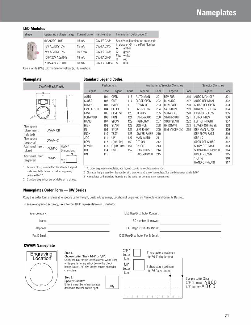
LED Modules
Shape Operating Voltage Range Current Draw Part Number Illumination Color Code k
6V AC/DC±10% 15 mA CW-EAQ2k Specify an illumination color code in place of k in the Part NumberA: amberG: greenPW: whiteR: redS: blue
12V AC/DC±10% 15 mA CW-EAQ3k
24V AC/DC±10% 16.5 mA CW-EAQ4k
100/120V AC±10% 18 mA CW-EAQHk
230/240V AC±10% 18 mA CW-EAQM4k
Use a white (PW) LED module for yellow (Y) illumination.
Nameplate Standard Legend Codes
CWAM–Black Plastic Pushbuttons Pushbuttons/Selector Switches Selector Switches
Legend Code Legend Code Legend Code Legend Code Legend Code
AUTOCLOSEDOWNEMERG.STOPFASTFORWARDHANDHIGHININCHJOGLOWLOWEROFFON
101102103104105106107108109110111112113114115
OPENOUTRAISERESETREVERSERUNSLOWSTARTSTOPTESTUPI (Int’l On)O (Int’l Off)EMO
116117118119120121122123125126127150151152
AUTO-MANCLOSE-OPENDOWN-UPFAST-SLOWFOR-REVHAND-AUTOHIGH-LOWJOG-RUNLEFT-RIGHTLOWER-RAISEMAN-AUTOOFF-ONON-OFFOPEN-CLOSERAISE-LOWER
201202203204205206207208209210211212213214215
REV-FORRUN-JOGRUN-SAFESAFE-RUNSLOW-FASTSTART-STOPSTOP-STARTUP-DOWNOI (Int’l OFF ON)
216217218219220221222223250
AUTO-MAN-OFFAUTO-OFF-MANCLOSE-OFF-OPENDOWN-OFF-SLOWFAST-OFF-SLOWFOR-OFF-REVLEFT-OFF-RIGHTLOWER-OFF-RAISEOFF-MAN-AUTOOFF-SLOW-FASTOFF-1-2OPEN-OFF-CLOSESLOW-OFF-FASTSUMMER-OFF-WINTERUP-OFF-DOWN1-OFF-2HAND-OFF-AUTO
301302303304305306307308309310311312313314315316317
1. To order engraved nameplates, add legend code to nameplate part number.2. Character height based on the number of characters and size of nameplate. Standard character size is 3/16”.3. Nameplates with standard legends are the same list price as blank nameplates.
Nameplate (blank insert included)
CWAM-OB
Nameplate (engraved)
CWAM-j
Additional Insert (blank)
HWNP-OHWNP Dimensions
27
12
Additional Insert (engraved)
HWNP-j
1. In place of j, insert either the standard legend code from table below or custom engraving delimited by “ “.
2. Standard engravings are available at no charge.
Nameplates Order Form — CW Series
Copy this order form and use it to specify Letter Height, Custom Engravings, Location of Engraving on Nameplate, and Quantity Desired.
To ensure engraving accuracy, fax it to your IDEC representative or Distributor.
Your Company: IDEC Rep/Distributor Contact:
Name: PO number (if known):
Telephone: IDEC Rep/Distributor Phone:
Fax & Email: IDEC Rep/Distributor Fax & Email:
CWAM Nameplate
Engraving Location
Step 1. Choose Letter Size - 7/64” or 1/8”.Check the box for the letter size you want. Then write your lettering in box below the check boxes. Note: 1/8” size letters cannot exceed 9 characters.
7/64”Letter Size
11 characters maximum(for 7/64” size letters)
1/8”Letter Size
9 characters maximum(for 7/8” size letters)
Step 2. Specify Quantity. Enter the number of nameplatesdesired in the box on the right.
Sample Letter Sizes7/64” Letters: A B C D1/8” Letters: A B C DQty
1 2 3 4 5 6 7 8 9 10 11
Nameplates
21

Precautions & Instructions
Operating Instructions
Safety PrecautionsTurn off the power to CW series switches before installation, removal, wiring and maintenance. Failure to turn power off may cause electrical shocks or fire hazard.
When wiring, use wires of a proper size to meet the voltage and current requirements. Tighten the M3.5 terminal screws to a tightening torque of 1.0 to 1.3 N·m. Failure to tighten the terminal screws may cause over-heating and fire.
Notes for Operation
When using the CW series switches in a safety-related circuit of a control system, observe safety rules and regulations of each country concerning particular applica-tions of the actual machines and facilities. Perform risk assessment before operation to ensure safety.
Operating Conditions
In corrosive gas or high-temperature, high-humidity environments, contact failure due to corrosion or color change or breakage of the housing may occur.Main parts of the CW series switches are made of plastic. Do not scratch the surface with a sharp object or apply excessive electric shock or load, otherwise the switches may be damaged. In particular, keep the button, lens and bezel from such damage, otherwise ap-pearance and function may be impaired.Do not apply detergents, cutting oils, or chemicals which may impair the function and appearance of the CW series switches.
Panel MountingFirst remove the contact block and then the locking ring from the operator. Insert the operator into the panel cut-out from the front, tighten the locking ring from the back, then install the contact block to the operator.
Mounting Hole1. Mounting hole dimensions are in compli-
ance with IEC60947-5-1.2. If the anti-rotation projection is removed
from the bezel, CW series switches can be mounted in ø22.3mm mounting holes. To remove the anti-rotation projection, remove the gasket and use cutting pliers to break the projection.
Illuminated Pushbuttons and Pilot LightsRemoving the LensTo remove the lens from an illuminated pushbutton or pilot light, insert a flat screwdriver under the flange of the lens at 90° from the TOP marking and twist the screwdriver.Do not insert the screwdriver too far and do not ap-ply excessive force to the lens, otherwise the bezel surface may be damaged.
Screwdriver Insertion DirectionTOP MarkingTOP Marking
Screwdriver Insertion Angle
Approx. 30°
Panel Surface
Installing the LensTurn the groove in the lens to the TOP marking on the operator housing. With the groove aligned with the ridge, press the lens in.
TOP Marking
Groove in the Lens
Ridge
MarkingMarking film can be applied for inscriptions or identification.
Applicable Marking Film Size Illuminated Pushbutton (Round Flush)Pilot Light (Round Flush, Round Extended)
Illuminated Pushbutton (Round Extended)
ø15.9
13.8 12.6
ø15.9
Thickness: 0.2 mm maximumFilm material: Polyester (recommended)Note: Film is not supplied and must be provided by the user.
Removing and Installing the Contact Unit1. To remove the contact block from the opera-
tor, push the yellow locking lever and turn it to the left.
Locking Lever
2. To install, align the TOP marking on the operator with the TOP marking on the contact block mounting adaptor, and turn the locking lever to the right.
Installation in Panel Cut-outRemove the locking ring from the operator. With the anti-rotation projection on the opera-tor aligned with the recess in the mounting hole, insert the operator into the mounting hole. Tighten the locking ring from the rear of the panel.
Note for Panel MountingWhen installing the operator in a panel cut-out, use the optional locking ring wrench (MW9Z-T1) to tighten the locking ring to a recommended tightening torque of 1.2 N·m. Do not use pliers and do not tighten excessively, otherwise the operator may be damaged.
TOP marking on selector and key selector switches
Locking Ring
Panel
TOP marking on illuminated pushbuttons, pushbuttons and pilot lights
Anti-rotation projectionRecess in mounting hole
22

Precautions & Instructions
800.262.4332www.IDEC.com/switches
Operating Instructions con’t
PushbuttonsPushbutton caps cannot be removed. Do not tamper with the cap using a screwdriver or pliers, otherwise it may be damaged.
Selector SwitchesTurn the selector operator or key to the detent positions.
Key Selector Switches
To prevent malfunction and damage, take the following precautions.
•Completely insert the key before turning.•Do not remove the key while turning.•Besides the standard key (0H), six other keys
are available. Use only a key with a number that matches the number on the switches’ key cylinder. (The standard key does not have a key number.)
•Keys are available in two shapes. -0H (standard), 1H, 2H: reversible keys -3H, 4H, 5H, 6H: non-reversible keys Make sure of correct insertion direction.
Contact Blocks and LED ModulesTo remove the contact block from the operator, insert a flat screwdriver under the latch and push the screwdriver down as shown below. Before removing the LED module, first remove all contact blocks, and then remove the LED module in the same manner.
WiringApplicable WiresStranded wire: 2.0 mm2 maximum (14AWG) Solid wire: ø1.6 mm maximum
8.0 max.
ø1.6
max
.
One or two wires can be connected to the terminal.
Applicable Crimping TerminalsSpade terminalWhen using crimping terminals, be sure to use insulating tubes or insulated crimping termi-nals.
11.5 max.
8.1 max.
6.9
max
.
3.6
min
.
0.5 min.
Crimping TerminalWire
Insulation Tube
FerruleWhen connecting two ferrules to one terminal, use ferrules without insulation.
8.0 max.
�1.
7 m
ax.
Insulation
8.0 max.
�1.
7 m
ax.
When using spade terminals or ferrules, ensure that they are inserted completely. Ring terminals cannot be used.
Screw Tightening TorqueTighten the M3.5 terminal screws to a recom-mended torque of 1.0 to 1.3 N·m.
23

©2013 IDEC Corporation. All Rights Reserved. Catalog No. CW9Y-B100-1 09/11 (PDF updated 08/13) 7.5K
www.IDEC.com
Think Automation and beyond...
Specifications and other descriptions in this catalog are subject to change without notice.
800.262.4332www.IDEC.com/switches
16mm LB Series Miniature Switches
With a choice of metallic or black plastic bezels, and flush or standard mounting, our newest miniature flush mount switches add style and safety to any application. All LB switches are UL recognized, TUV approved, CSA certified and CE marked, as well as provide an IP65 degree of protection. Available in illuminated pushbuttons, pushbuttons, pilot lights, selector switches and key selector switches, these switches are perfect for use with instrumentation, communication equipment, computer peripheral, telecom, medical equipment, food and beverage processing equipment, semi-conductor equipment, non-industrial applications (train cab, parking machines, audio/visual equipment), panels and more!
USAIDEC CorporationTel: (408) [email protected]
CanadaIDEC Canada Ltd.Tel: (905) [email protected]
AustraliaIDEC Australia Pty. Ltd.Tel: [email protected]
JapanIDEC CorporationTel: +81-6-6398-2571 [email protected]
United KingdomIDEC Electronics Ltd.Tel: +44-1256-321000 [email protected]
GermanyIDEC Elektrotechnik GmbHTel: [email protected]
Hong KongIDEC (H.K.) Co., Ltd.Tel: +852-2803-8989 [email protected]
China/BeijingIDEC (Beijing) CorporationTel: +86-10-6581-6131
China/ShanghaiIDEC (Shanghai) CorporationTel: [email protected]
China/ShenzhenIDEC (Shenzhen) CorporationTel: +86-755-8356-2977
SingaporeIDEC Asia Pte. Ltd.Tel: +65-6746-1155 [email protected]
TaiwanIDEC Taiwan CorporationTel: +886-2-2698-3929 [email protected]