Idaho National Investigation of Low-Cost LNG Vehicle Fuel...
45
Idaho National Engineering Laboratory IN EEUEXT-98-00214 February 1998 Investigation of Low-Cost LNG Vehicle Fuel Tank Concepts J. E. O’Brien A. Siahpush LOCKHEED MARTIN *
Transcript of Idaho National Investigation of Low-Cost LNG Vehicle Fuel...

Idaho National
Engineering Laboratory
IN EEUEXT-98-00214
February 1998
Investigation of Low-Cost LNG Vehicle Fuel Tank Concepts
J. E. O’Brien A. Siahpush
L O C K H E E D M A R T I N *

.-
'- I
INEEL/EXT-98-00214
Investigation of Low-Cost LNG Vehicle Fuel Tank Concepts
. Final Report
(GFU-98/0015)
Prepared by
J. E. O'Brien and A. Siahpush
January, 1998
Idaho National Engineering and Environmental Laboratory P. 0. Box 1625
Idaho Falls, ID 83415
for Gas Research Institute
Contract No. 5096 940 3732
GFU Contract Manager Alissa Oppenheimer
R Technical Manager, Natural Gas Vehicles
WTRBUTtON OF THIS DOCUMENT IS UNtlMiEQ /.
This work was performed under the auspices of the U.S. Department of Energy, DOE Operations Office contract DE-AC07-94ID13223

DISCLAIMER 3
This report was prepared as an account of work sponsored by an agency of the United States Government Neither the United States Government nor any agency thmof. nor any of their employees, makes any warranty, express or implied, or assumes any legal liabiiity or responsibility for the accuracy, completeness, or use- fulness of any information, apparatus, product, or proass disclosed, or represents that its use would not infringe privately owned rights. Reference hmin to any spe- cific commercial product, process, or d c c by trade name, trademark, manufac- turer, or otherwise does not necessarily constitute or imply its endorsement, mom- mendation, or favoring by the United States Government or any agency thmof. The vim and opinions of authors expressed herein do not n d y state or reflect those of the United States Government or.any agency thmof.
.

Research Summarv
Title
Contractor
GRI Contract No.
Principal Investigators
Project Manager
Report Period
Objective
Technical Perspective
Results
Investigation of Low-Cost LNG Vehicle Fuel Tank Concepts
Idaho National Engineering and Environmental Laboratory Lockheed Martin Idaho Technologies
50969403732
J. E. O’Brien, Ali Siahpush
Bruce Wilding
October, 1996 to October, 1997
The objective of this study was to investigate development of a low-cost liquid natural gas (LNG) vehicle fuel storage tank with low fie1 boil-off, low tank pressure, and high safety margin.
One of the largest contributors to the cost of converting a vehicle to LNG is the cost of the LNG fie1 tank. To minimize heat leak fiom the surroundings into the low-temperature fuel, these tanks are designed as cryogenic dewars with double walls separated by an evacuated insulation space containing multi-layer insulation. The cost of these fuel tanks is driven by this double-walled construction, both in terms of materials and labor. The primary focus of the analysis was to try to devise a fuel tank concept that would allow for the elimination of the double-wall requirement.
Results of this study have validated the benefit of vacuum/MLI insulation for LNG fuel tanks and the difficulty in identifying viable alternatives. The thickness of a non-vacuum insulation layer would have to be unreasonably large to achieve an acceptable non-venting hold time. Reasonable hold times could be achieved by using an auxiliary tank to accept boil-off vapor from a non-vacuum insulated primary tank, if the vapor in the auxiliary
.. 11
tank can be stored at high pressure. High pressure can be realized in the auxiliary tank either through the use of a small compressor located between the primary and auxiliary tanks or by allowing the primary tank to achieve a high pressure prior to venting. The first option is expensive and the second option is inconsistent with one of the primary objectives of the study, which is to develop a low-cost LNG fuel tank while maintaining low- pressure. The effect of incorporation of a reasonable thickness of phase- change material into the thickness of a LNG-tank insulation layer was analyzed. A hold-time extension of approximately one day is achievable, assuming the phase-change material is fully frozen at the onset of venting. Refreezing of the phase-change material requires approximately 6 hours of engine operation.
Technical Approach The primary focus of the analysis was to try to devise a fuel tank concept that allowed for the elimination of the double-wall requirement. Thermodynamic relations were developed for analyzing the fuel tank transient response to heat transfer, venting of vapor, and out-flow of either vapor or liquid. A review of vacuum and non-vacuum insulation systems was performed and case studies were presented. Several hold-time- extension concepts were considered including the use of conventional non- evacuated insulation, the use of a phase-change thermal energy storage material imbedded in a conventional insulation layer, and the use of an auxiliary storage tank to accept the boil-off from the primary fuel tank. Consideration was also given to the possibility of using alternate materials such as aluminum or composites for tank fabrication.
Project Implications One of the major costs associated with conversion of a vehicle to LNG fuel is the cost of the LNG fuel tank. The cost of these tanks is driven by the cryogenic nature of the fuel and by the fundamental design requirements of long non-venting hold times and low storage pressure. This report provides analysis of several concepts for LNG fuel storage in single-walled tanks. In addition, tools for general thermodynamic analysis of LNG fuel tanks are provided.
... 111

......
Table of Contents
...................................................................................................................... .. Research Summary ll
List of Figures V Nomenclature vi
............................................................................................................................
............................................................................................................................
...........................................................................................................................
V List of Tables '.
1 . 0 Introduction and Background ............................................................................................... 1
2.0 Thermodynamic behavior of cryogenic storage tanks ............................................................. 2 2.1 Relationship between Pressurization Rate and Heat Leak rate ................................... 3 2.2 Venting Rates for Idle Tanks ..................................................................................... 6 2.3 Pressure Drop Associated with Liquid Fuel Delivery ................................................. 7 2.4 Pressure Drop Associated with Vapor Fuel Delivery ................................................. 8
3.0 Thermal Insulation Options for Small Cryogenic Tanks ........................................................ 10
3.1.1 Vacuum Insulation Performance ................................................................ 10 3.1.2 Case Study ................................................................................................ 11
3.2 Review of Non-Vacuum Insulation Technologies ..................................................... 12
3.1 Review of current vacuum/MLI technology ............................................................. 10
3.2.1 Effect of Pressure and Temperature on Thermal Conductivity .................... 16 3.2.2 Relationship of Insulation Thickness to Hold Time .................................... 17
4.0 Concepts for Hold-time Extension for LNG Fuel Tanks ..................................................... 19 4.1 Auxiliary Tank Concept .......................................................................................... 19 4.2. Incorporation of a Phase-Change Thermal Energy Storage ..................................... 24
Material in a Non-Vacuum-Insulation System
5.0 Alternative Tank Materials ................................................................................................. 28 5.1 Composite Materials for Cryogenic Tanks ................................................................ 28 5.2 Aluminum vs . Stainless Steel for Cryogenic Tanks ................................................... 30
6.0 Use of Hydrates for LNG Fuel Storage ............................................................................... 32 6.1 Advantages ofthe Use of Hydrates .......................................................................... 32 6.2 Disadvantages ofthe Use of Hydrates ...................................................................... 33
7.0 Summary and Conclusions .................................................................................................. 33
References .......................................................................................................................... 35

... _-.- ... . . . . . . . . . . . ....... I.._ ..... ”.
List of Tables
Table 3.1 Heat transfer due to radiation in hard vacuum .......................................................... 11 Table 3.2 Molecular conduction heat transfer at different levels of vacuum .............................. 12 Table 3.3 Table 3.4 Heat transfer comparison ......................................................................................... 14 Table 3.5
Apparent thermal conductivity of various insulation materids ................................... 13
Cornparkon of several cryogenic insulation systems ................................................. 14 Table 4.1. Representative Pressure-Rise Rates for 70-gallon LNG tank, .................................. 21
initially 2/3 liquid-full Table 4.2 Vent Flow Rates for Super-critical Methane ............................................................ 22 Table 4.3. Hold-time estimates for auxiliary tank concept ......................................................... 24
Table 5.1 Stainless steel sizes and price ................................................................................... 31 Table 5.2 Sizes and price of aluminum sheets ........................................................................... 31
Table 4.4. Candidate Phase-Change Thermal Energy Storage Materials .................................... 26
List of Figures
Figure 2.1 LNG tank pressurization test ..................................................................................... 6 Figure 3.1 Effect of Pressure and temperature on thermal conductivity
of fiber glass blanket insulation ................................................................................. 16 Figure 3.2 Insulation thickness as a hnction of hold time for several
nonevacuated insulation systems .............................................................................. 18 Figure 4.1 Tank pressure vs . time for 2-tank concept ................................................................ 23 Figure 4.2 Schematic of insulation layer with phase-change material ......................................... 25
V

Nomenclature
thermal conductivity temperature dependence factor (K-1)
specific heat
accommodation factor
a
CP
Fa
HCW total enthalpy of control volume (Jkg)
enthalpy (Jkg) specific enthalpy of saturated liquid (Jkg)
specific enthalpy of saturated vapor (Jkg)
enthalpy of vaporization (Jkg)
enthalpy of hsion (Jkg)
thermal conductivity (W/m K)
total mass of LNG inside tank (kg)
mass flow rate (kg/s)
mass of liquid (kg)
k
m
m
mf
mass of vapor (kg)
pressure (Pa) rate of saturation pressure rise inside tank due to heat leak ( P a l s )
P dp
dt
Q SA
rl
heat leak rate (W)
heat transfer rate per unit length (W/m)
outer radius of the inner tank (m)
inner radius of the outer tank (m) r2
ri inner radius of insulation layer (m)
outer radius of insulation layer (m)
specific gas constant (Jkg K)
Stefan-Boltzmann constant (W/m2 K4) gas temperature (K)
R
temperature (K) T
vi

’ 4
temperature difference (K)
time(s)
total internal energy of control volume (Jkg)
specific volume (m3kg)
specific volume of saturated liquid (m3kg)
specific volume of saturated vapor (m3kg)
change in specific volume with vaporization (m3kg)
total volume of liquid plus vapor (m3)
work rate or power (W)
mg/m thermodynamic quality of two-phase he1
derivatives of saturation-state properties with respect to pressure
volumetric thermal expansion coefficient (K-1)
surface emissivity
specific heat ratio
density (kg/m3)
vii

1.0 Introduction and Background
This report is the result of a study which was performed at the Idaho National Engineering and Environmental Laboratory (INEEL) under contract with the Gas Research Institute (GN), contract No. 5096 940 3732. The objective of this study was to investigate development of a low-cost (capital and maintenance) LNG vehicle fuel storage tank with low &el boil-off, low tank pressure, and high safety margin. The LNG fuel tank represents one of the major expenses associated with conversion of a vehicle to LNG. LNG vehicle fuel tanks are necessarily designed to minimize heat transfer fkom the surroundings to the cryogenic fuel, which is stored in the fuel tanks as a saturated liquid at a pressure of 580 - 1700 kPa (70 - 250 psig). Corresponding saturation temperatures are in the 137-to 160 K (-208 to -172" F) range. During time periods of fuel storage, heat which leaks fiorn the surroundings to the LNG fuel will cause the fuel saturation pressure to increase, eventually leading to venting of vaporized &el. The low temperature of the LNG fuel and the desire to minimize fuel venting necessitates a &el tank design, which incorporates low heat leak rate as a primary design feature. Currently available LNG vehicle fuel tanks utilize a cryogenic dewar design in which an inner fuel storage tank is surrounded by an outer tank with an evacuated space between the inner and outer tanks. Multi-layer insulation is located in the space between the tanks in order to reduce radiation heat transfer. The inner tank is a pressure vessel, which must be designed to withstand a pressure determined by the set point value on the venting and pressure-relief valves, with an appropriate factor of safety, at cryogenic temperatures. The outer tank must be able to withstand atmospheric pressure (with vacuum on the inside) plus be rugged enough to survive moderate abuse. Currently available commercial LNG vehicle &el storage tanks are fabricated from stainless steel for both the inner and outer tanks, with minimal inter-tank support structure. All fluid transport piping penetrations must be sized to allow reasonable flows in and out. The penetrations should provide a minimal heat leak path, must be fully sealed at both the inner and outer tank walls, and must be flexible enough to withstand significant differential thermal expansiodcontraction that results fiorn temperature swings during refueling and vehicle operation. These tank thermal, structural and materials issues all contribute to the high cost of LNG fuel tanks and were therefore all taken into consideration in this study, while attempting to identifl some logical alternatives for the development of a low-cost tank.
A literature search on LNG vehicle fuel tanks produced surprisingly few relevant technical articles. Standards for tank construction, heat leak, structural integrity, etc. are spelled out in NFPA 57 [l]. A description of tank design features for LNG vehicular fuel systems is provided in reference [2], including details on structural supports, vacuum insulation, fuel flow systems,
. . . . . i . . . ..
vaporizer, and pressure control. A useful thermodynamic analysis of pressure response to heat leaks, stirring, and venting of cryogenic storage tanks is provided in [3]. Safety issues related to both CNG and LNG fuel tanks for automobile usage are addressed in references [4 - 61. Guidelines for testing and evaluation of the durability of LNG fuel storage tanks are provided in reference [4]. Safety issues discussed in [SI include fie and explosion, venting in enclosed spaces, accidents, component failure, tank filling, and tank repair. Reference [6] is a comprehensive report prepared by SAIC for GRI which includes a section on fuel storage and transfer, and another section on LNG vehicle operation. Several papers were found which provided technical descriptions of vehicle conversions to LNG he1 performed by university engineering students. This program, which involved about 25 universities, was sponsored by General Motors. A discussion of LNG fuel characteristics, tank boil-off rates, and fuei weathering effects is provided in reference [8]. An overview of LNG economics and infiastructure issues for vehicle fleet operations is presented in reference [9]. Heat-leak-driven venting of %el from small storage tanks can cause changes in he1 composition, which can affect engine performance. Issues and test results related to LNG fuel weathering in vehicle %el storage tanks are presented in [ 101.
An example is provided in reference [7].
The four main sections (2 - 5) of this report reflect the technical tasks, which were performed as a part of this study. Section 2 deals with the fbndmental thermodynamic behavior of cryogenic storage tanks subjected to heat leaks, inflows, and outflows. Section 3 provides a review of insulation systems, both vacuum and non-vacuum, with applications focused on small cryogenic tanks. The possibility of achieving significant cost reduction by elimination of the double-walled evacuated design is examined. Section 4 explores some concepts for increasing the hold-time of non-vacuum-insulated cryogenic fuel storage tanks. Section 5 is focused on possible alternate tank materials such as aluminum or composites.
2.0 Thermodynamic Behavior of Cryogenic Storage Tanks
A cryogenic fuel storage tank can be modeled as an insulated tank containing saturated liquid and saturated vapor, an inlet penetration and two outlet penetrations, one from the vapor space and one from the liquid space. Based on this simple model, the thermodynamic behavior of these tanks in various situations can be analyzed. These analyses will be use l l in assessing the performance of proposed low-cost fuel tank concepts and in evaluating test results. The calculations presented in this report allow for the estimation of tank heat leak rate based on the rate of pressure increase prior to venting, constant-pressure venting rate for a specified heat-leak, pressure drop rate associated with liquid fuel delivery during vehicle operation, vapor backfill
2
. . . .. ..A . . . - . . _ . , . . . . . . . . . . I . . . . . ,
flow rate required to maintain constant tank pressure during vehicle operation, and the pressure drop rate associated with withdrawal of vapor from the tank. Consideration of these various phenomena leads directly to an understanding of the reasons for the various design features incorporated into currently available commercial fuel tanks. The symbols used in this report are all defined in the Nomenclature section at the beginning of the report.
2.1 Relationship between Pressurization Rate and Heat Leak rate
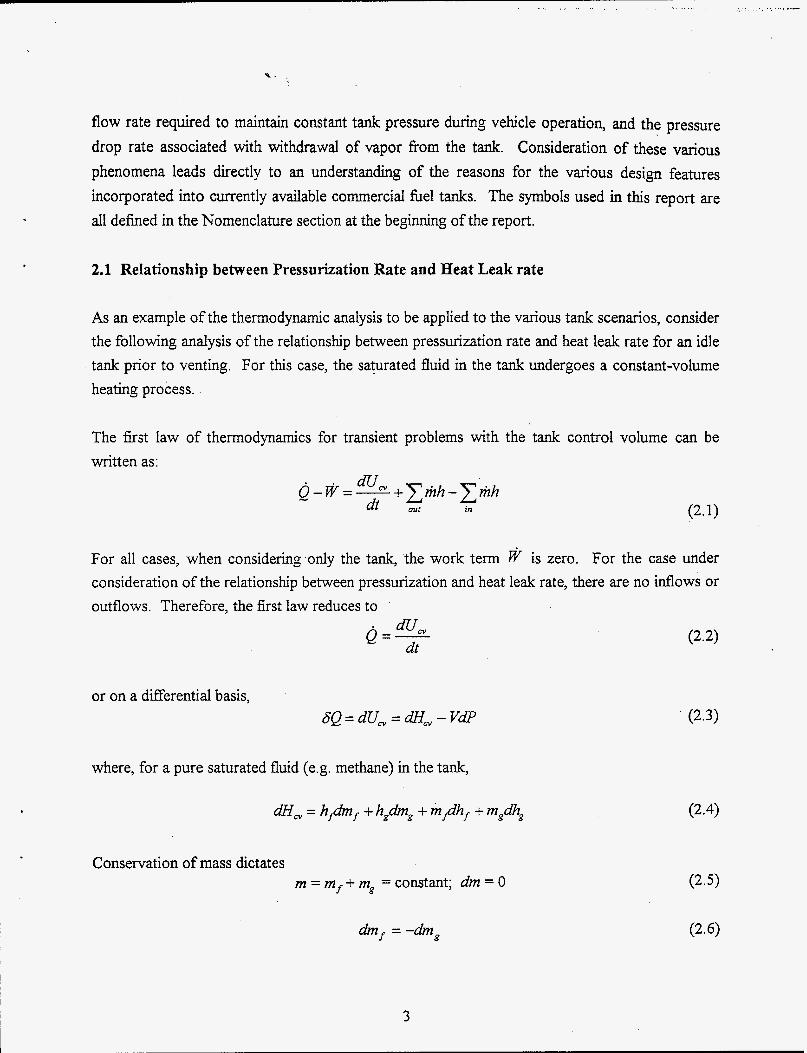
As an example of the therinodynamic analysis to be applied to the various tank scenarios, consider the following analysis of the relationship between pressurization rate and heat leak rate for an idle tank prior to venting. For this case, the saturated fluid in the tank undergoes a constant-volume heating process.
The first law of thermodynamics for transient problems with the tank control volume can be written as:
For all cases, when considering.only the tank, the work term @ is zero. For the case under consideration of the relationship between pressurization and heat leak rate, there are no inflows or outflows. Therefore, the first law reduces to
. dU, e=,
or on a differential basis,
where, for a pure saturated fluid (e.g. methane) in the tank,
= h#m + hgdmg + m/hf + m,dhg
Conservation of mass dictates m = inf + mg = constant; dm = 0
dm = -dmg
3

So therefore a'H, = h/,din, + m dhf + m,dh,
and from the constant-volume constraint:
Y = m v + mgv, = constant
dV=O=mfdvf +m,dvg+vfdinf +vgd2n,
which yields mfdvf + m,&, .
vfg dm, =,
Substituting the expressions for and din, into the first law, eqn. (2.3), yields
hfg SQ = -- (mf dv, + mgdvg )+ m dhf + mgdhg - V i v f g
which can be expressed on a rate basis as
and finally noting that 5 x = A ; l - x =
m
m m
the desired result is obtained
(2.10)
(2.11)
(2.12)
(2.13)
(2.14)
This result relates the rate of pressure increase in a non-venting LNG fuel storage tank to the heat leak rate. It can be used to estimate the heat leak rate for a tank when the pressure-rise rate is known or alternately it can be used to estimate the pressure-rise rate when the heat leak rate is known. Note that the derivatives of thermodynamic saturation-state properties with respect to
4

saturation pressure must be evaluated. These derivatives are state hnctions and are not constant with respect to pressure.
Available commercial on-board-vehicle LNG fuel storage tanks are double-walled stainless-steel vacuum-insulated tanks with very low heat-leak rates such that the non-venting he1 retention time is approximately 7 days for a 70-gallon tank. During this 7-day period, tank pressure increases f7om the typical operating pressure of 80 psi to 240 psi at which time a venting pressure-relief valve opens. This hold-time information is suflicient to estimate the heat leak rate into the tanks by applying eqn. (14). Application of eqn. (14) to the case of a 2/3-liquid-full70-gallon LNG &el tank (methane properties are assumed to be representative) undergoing the 7-day non-venting hold time predicts a heat-leak rate of approamately 12 W, which is consistent with manufacturer data and operational exierience at INEEL. Assuming a 2-inch inter-tank spacing, this heat leak rate corresponds to an overall tank effective thermal conductivity of 0.0013 W/m K. The actual thermal conductivity of the evacuated multi-layer insulation is probably about an order of magnitude smaller than this, but the overall value includes the heat leaks associated with the various tank penetrations. The best non-evacuated insulation systems provide a thermal conductivity approaching that of air, approximately 0.026 W/m K. This is a factor of twenty higher than the overall effective conductivity associated with the 7-day non-venting hold time described above. Clearly it would be difficult to devise a he1 tank having a reasonable hold time without using an evacuated double-walled tank design. However, it is premature to conclude that this is an impossible goal. More carehl consideration of the primary sources of heat leaks in existing tanks is required. For example, if the penetrations contribute a sigdicant fraction of the heat leak on existing tanks, it may be possible to improve the thermal design of the penetrations such that a higher effective conductivity insulation scheme (perhaps with an increased insulation thickness) could be adopted for the remainder of the tank.
Equation (2.14) can also be applied during testing of prototype tank designs to estimate heat leak rates. The relationship shows that it is not necessary to allow venting of the tank in order to determine the heat leak rate from mass loss measurements associated with boil-oE It is only
necessary to monitor the pressure rise rate of a non-venting tank. For example, tests were performed at INEEL on a 17-gallon LNG tank as part of a separate study. For these tests, tank pressure was monitored over a 2-day period, yielding the results presented in Fig. 2.1. The results indicate an average pressure rise rate of 2.47 psi/hr or 4.73 Pa/s. This pressure rise rate corresponds to a heat leak rate of 6.3 W for this tank. Note that the hold time for this 17-gallon tank would only be about 2.5 days (compared to 7 days for the 70-gallon tank) since the pressure
5

would rise ii-om 80 psi to 230 psi in that time. Smaller tanks exhibit shorter hold times due to their inherently higher surface area-to-volume ratio.
200
180
160 M
a .r(
v1
120
100
80
I E I I Y = MO + Ml*X
-- R 0.99816
L I I
t
= 4.73 Pals
Corresponds to a 6.3 W heat leak rate For a 17-gallon tank
0 5 10 15 20 25 30 35 time, hrs
Figure 2.1. LNG tank pressurization test.
2.2 Venting Rates for Idle Tanks
When a vehicular LNG fuel storage tank is idle for a period exceeding its hold time, the tank pressure will reach a level of approximately 230 psi at which time a pressure-relief valve will open and venting will occur in order to assure that tank over-pressurization does not occur. Application of the first law of thermodynamics yields an expression for the rate of venting during this constant-pressure process:
Q mvenr = -) (2.15)
.
_ _ _ _
\ I
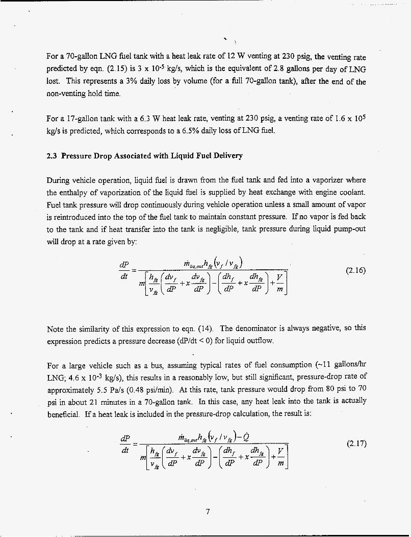
For a 70-gallon LNG fuel tank with a heat leak rate of 12 W venting at 230 psig, the venting rate predicted by eqn. (2.15) is 3 x kg/s, which is the equivalent of 2.8 gallons per day of LNG lost. This represents a 3% daily loss by volume (for a full 70-gdlon tank), after the end of the non-venting hold time.
For a 17-gdon tank with a 6.3 W heat leak rate, venting at 230 psig, a venting rate of 1.6 x 10⁵ kg/s is predicted, which corresponds to a 6.5% daily loss of LNG fuel.
2.3 Pressure Drop Associated with Liquid Fuel Delivery
During vehicle operation, liquid fuel is drawn from the fuel tank and fed into a vaporizer where the enthalpy of vaporization of the liquid fuel is supplied by heat exchange with engine coolant. Fuel tank pressure will drop continuously during vehicle operation unless a small amount of vapor is reintroduced into the top of the fuel tank to maintain constant pressure. If no vapor is fed back to the tank and if heat transfer into the tank is negligible, tank pressure during liquid pump-out will drop at a rate given by:
(2.16)
Note the similarity of this expression to eqn. (14). The denominator is always negative, so this expression predicts a pressure decrease (dP/dt < 0) for liquid outflow.
For a large vehicle such as a bus, assuming typical rates of fuel consumption (-11 gallonsh LNG; 4.6 x kg/s), this results in a reasonably low, but still significant, pressure-drop rate of approximately 5.5 Pals (0.48 psi/min). At this rate, tank pressure would drop from 80 psi to 70 psi in about 21 minutes in a 70-gallon tank. In this case, any heat leak into the tank is actually beneficial. If a heat leak is included in the pressure-drop calculation, the result is:
7
(2.17)

..- . . . . . . . . .
,
Assuming a typical heat leak rate of 12 W, the pressure drop rate is reduced 25% to 4.1 P d s (0.36 psi/min). In order to avoid this loss of tank pressure, a small amount of vaporized fuel exiting the vaporizer can be reintroduced to the top of the fuel tank to maintain the desired operating pressure. The ratio of mass flow rate of saturated vapor to liquid outfIow required to maintain constant fuel tank pressure for adiabatic conditions is given by the simple expression:
(2.18)
For methane at 650 kPa (about 80 psig), this ratio is 0.027, which means that avapor mass flow equal to 2.7% of the liquid mass flow leavhg the tank should be reintroduced to the top of the fuel tank as vapor (from the outlet side of the vaporizer) in order to maintain a constant tank pressure. This pressure control can be accomplished using a passive design with a pressure regulator. This feature also allows fuel outflow to be driven by tank pressure [2].
An alternative pressure maintenance method would, be to somehow supply additional thermal energy to the tank contents during vehicle operation to supply the required enthalpy of vaporization of liquid to vapor associated with the falling liquid level inside the tank. The necessary thermal energy is obtained by setting dP/dt = 0 in eqn. (2.17):
(2.19)
For the 70-gallon bus tank-with a liquid he1 outflow rate of 4.6 x 10⁻³ kg/s, a total of 50 W of thermal energy addition would be required to maintain constant pressure. Thermal energy could be added using a small electric heater located in the fuel volume or it could be added via a heat exchanger in which warm vaporized fuel passes through a coiled tube located inside the fuel volume [ 1 11.
2.4 Pressure Drop Associated with Vapor Fuel Delivery
If an LNG fuel tank has been idle for a long period, tank pressure may be well above the desired operating pressure due to heat leaks into the tank. In order to quickly return the tank pressure to the desired lower pressure, it is advantageous to draw fuel directly from the top of the tank as vapor until the pressure has returned to the desired operating level. This is typically achieved
8
through the use of an pressure control valve [7]. The rate of pressure drop associated with this process is given by:
(2.20)
Note that this result is very similar in form to the result shown in Eqn. (2.16) for pumping liquid out of the tank. However, the numerator now includes the factor (1 + vf /vk) instead of vf I vg . Consequently, the magnitude of the pressure-drop rate for a specified fuel mass flow rate is much higher when drawing vapor from the tar$ than when drawing liquid. In particular, 'for an operating tank pressure of 80 psig, the rate of pressure drop when drawing vapor from the tank is a factor of 42 higher than when drawing liquid from the tank. After the tank pressure has returned to the desired operating level, the passive control system should once again begin drawing liquid from the bottom of the tank, with a small return feed of vapor to the top of the tank to maintain tank pressure, as discussed earlier.
Results of the above analyses lead directly to an understanding of the motivation for several typical design and control features of current LNG vehicle fuel tanks. These features include the double-walled vacuum-insulated design with all its associated complications, the incorporation of a control system which allows for vapor backfill of the tank in order to maintain constant tank pressure during vehicle operation, and the ability to draw vapor from the tank instead of liquid if the tank pressure is too high (such as after a long idle period) in order to quickly return the tank pressure to the desired operating level. Long periods of tank idleness lead to pressure increase and eventual venting, which for a typical heat leak rate leads to a loss of fuel inventory of about 4% per day for a 70-gallon tank. The necessity to vent an idle tank precludes the usage of LNG for personal vehicles unless some passive method such as a catalytic converter can be developed to process the vented fuel such that only carbon dioxide and water are ultimately released to the atmosphere.
9

. . . .. . . . . - .. . .
3.0 Thermal Insulation Options for Small Cryogenic Tanks
3.1 Review of current vacuum/MLI technology
A critical component of any cryogenic system is the manner in which the low-temperature fluid is stored. Cryogenic storage vessels are designed to contain saturated fluid at an appropriate pressure and temperature while minimizing the heat leak into the vessel. Heat leak gives rise to an increase in temperature and pressure and eventual loss of fluid through a pressure relief valve. Cryogenic storage vessel design has become standardized as a result of the wide use and application of cryogenic fluids. Storage vessels for these fluids range in size fiom 1-liter flasks used in the laboratory for liquid nitrogen to 160,000 m3 double-walled tanks for temporary storage of liquefied natural gas (LNG). These cryogenic storage vessels range in type &om low- performance containers, insulated with rigid foam, cork, or fibrous insulation to high-performance containers, insulated with evacuated multilayer insulation (MLI). The overriding factors in determining the type of container chosen for a particular application are economics and safety. Large tanks have a large surface-area-to-volume ratio and can effectively utilize a non-evacuated double-walled design with perlite insulation, with low percentage fluid loss rates. For small tanks, a high-performance container utilizing a double-walled vacuum-insulation strategy is often required.
In this section, various insulation concepts are considered for use in small-scale cryogenic storage systems. The performance of these concepts will be compared and summarized,
3.1.1 Vacuum Insulation Performance ,
With vacuum insulation, the evacuation of the gas between the inner and outer tank walls vastly reduces the number of gas molecules available to transport thermal energy from the warm surface to the cold surface, thereby greatly reducing overall heat transfer rates. In the vacuum system, depending on the degree of vacuum, gaseous convection is essentially eliminated and conduction through the residual gas is significantly reduced. Consequently, thermal radiation from the warm surface to the cold surface becomes the dominant heat transfer mode. It can be estimated for two parallel walls by
2nr,a(1;4 - T;) (4 J k d =
‘ I
where subscripts 1 and 2 refer to first and second surfaces.
10

Heat transfer due to fiee molecular conduction is not significant in high-vacuum systems. For soft vacuums, however, it may be significant and can be evaluated using the following relation.
# of shields 0 1 qll (Wlm) 15.89 7.53
. _...r,+cI . , ._ ..
2 3 4 4.21 2.92 2.23
To reduce thermal radiation, it is advantageous to locate several radiation shields of highly reflective material between the warm and cold surfaces. For N identical shields located between the hot and cold surfaces, the heat transfer rate is given as
where E~ is the emissivity of the identical shields. Obviously, as more shields are added, the heat
transfer rate per unit length decreases.
3.1.2 Case Studv
For this sample analysis, a typical on-board-vehicle LNG fuel tank is considered. The tank is fabricated from double-walled stainless steel inner and outer tanks with rl = 0.203 m (8'7, r2 =
0.254 m (lo"). Inner and outer tank wall temperatures are assumed to be TI = 138.5 K, and T2 =
300 K, respectively. This inner tank temperature corresponds to the saturation temperature of methane at 582 kPa (84 psia). Several hard-vacuum cases have been analyzed and results are shown in Table 3.1 . It should be noted that the heat transfer associated with structural supports and piping penetrations has not been considered here.
Results indicate that the effectiveness of the radiation shielding will decrease significantly once the number of shields is greater than about 3 . Nevertheless, most small cryogenic tanks have at least 7 layers of radiation shielding located in the vacuum space between the inner and outer tanks.
11
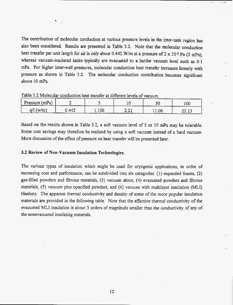
The contribution of molecular conduction at various pressure levels in the inter-tank region has also been considered. Results are presented in Table 3.2. Note that the molecular conduction heat transfer per unit length for air is only about 0.442 W/m at a pressure of 2 x 10⁻³ Pa (2 e a ) , whereas vacuum-insulated tanks typically are evacuated to a harder vacuum level such as 0.1 @a. For higher inter-wall pressures, molecular conduction heat transfer increases linearly with pressure as shown in Table 3.2. The molecular conduction contribution becomes significant above 10 @a.
Pressure (mPa)
qA (w/m) 2 5 10 50 100
0.442 1.106 2.21 11.06 22.13
Based on the results shown in Table 3.2, a soft vacuum level of 5 or 10 mPa may be tolerable. Some cost savings may therefore be realized by using a soft vacuum instead of a hard vacuum. More discussion of the effect of pressure on heat transfer will be presented later.
3.2 Review of Non-Vacuum Insulation Technologies.
The various types of insulation which might be used for cryogenic applications, in order of increasing cost and performance, can be subdivided into six categories: (1) expanded foams, (2) gas-filled powders and fibrous materials, (3) vacuum alone, (4) evacuated powders and fibrous materials, (5) vacuum plus opacified powders, and (6) vacuum with multilayer insulation (MLI) blankets. The apparent thermal conductivity and density of some of the more popular insulation materials are provided in the following table. Note that the effective thermal conductivity of the evacuated MLI insulation is about 3 orders of magnitude smaller than the conductivity of any of the nonevacuated insulating materials.
12

Table 3.3 Apparent thermal conductivity of various insulation materials. Insulation
Nitrogen (0.101 MPa) Foam insulation
Polystyrene Polyurethane Glass
Perlite Silica Aerogel Fiberglass
Perlite Silica Aerogel Fiberglass
50150 wt. % AVSantocel
Al foil and Fiberglass (30 to 60 layers per cm) Al foil and nylon net (3 1 layers per cm) Al crinkled, Mylar film (35 layers per cm)
Nonevacuated powders
Evacuated powders and fibers (0.13 mPa)
Opacified powders (0.13 mPa)
Multilayer Insulation Blanket ( 1 . 3 ~ 1 O4 mPa)
Density (kg/m3>
1.12
46 11 140
50 80 110
50 80 50
160
Thermal conductivity at 190 K
(rnW/m K) 17
26 33 35
26 19 25
1 1-2 7-2.1 1.7
0.35
0.017 0.035 0.042
A comparison of the effectiveness of vacuum insulation (with or without radiation shielding) to the effectiveness of non-vacuum systems is provided in the following table. The typical on-board- vehicle LNG fuel tank is again considered with the same inner-tank dimensions and overall temperature difference as considered previously. The calculations indicate the thickness of insulation required to achieve the same heat leak rate per unit length as for (a) hard vacuum without shielding (15.89 W/m) and for (b) hard vacuum with 2 radiation shields (4.21 W/m). In case (a), the insulation layer is considered to be non-evacuated. In case (b), the insulation layer is assumed to be evacuated to a soft vacuum level (0.13 Pa). Insulation material thermal conductivities at 300 K were used for this comparison, so no credit is taken for the fact that the thermal conductivities decrease with temperature.
.
13

Thickness of wt (kg) insulation thermal cond., Density
(a) non-evacuated insulation compared with hard vacuum and no radiation shields
145 11 1.577 108
300K (Wlm K) (kg/m3) insulation (m)
Polystyrene foam 0.026 46 0.817 Polyurethane foam 0.035
Silica aerogel (b) insulation in soft vacuum (0.13 pa) compared with hard vacuum and 2 radiation shields
13.3 Silica aerogel 0.0019 80 0.104 fiberglass
50150 wt% AVSantocel
Results shown in Table 3.4 indicate that, regardless of the type of non-evacuated insulation system used, if there is a constraint on available space and mass, a hard vacuum with radiation shields provides the only viable insulation solution. For example, a thickness of polystyrene foam of 0.814 m would be required to provide the same insulation effectiveness as a hard vacuum with no radiation shields. The thermal conductivity of a non-evacuated insulation would have to be less than 0.002 W/m K in order to provide an effective insulation with a reasonable thickness.
0.0017 50 0.091 7 0.00035 160 0.016 3.4
Data related to several cryogenic insulation materials has been obtained. Advantages and
Advantages
disadvantages of these insulation materials are described in the following table.
1. Expanded Perlite: Other names: Brelite, Cecaperl, Perlox, Pulvinsul, Ryolex. Low thermal conductivity, low density, low cost, readily available, nonflammable, nontoxic, can be produced on site, easy to install, easy to evacuate, usefid in vacuum insulation, and easy to apply to irregular shapes. 2. Fiberrrlass Low thermal conductivity, easy to handle, recoverable after water contact, and readily available.
ition systems. Disadvantages
Easily damaged during handling, dusty, abrasive, can not be used on moving parts, conductivity may change with time, high thermal contraction; requires protection from atmosphere.
Expensive, required careful packing for best result, difficult to use with vacuum, requires protection from atmosphere.
14

~
3. Mineral or Rock Wood Other names: Banroc, Eldorite, Fluffex, Insulwool, Rocksil, Stillite. Relatively inexpensive, readily available, and free from h e dust. 4. Silica Aeroeel Other names: Aerosoil, Cab-0-Sil, Santocel. No settling, and easy to use in vacuum.
5 . Basic Magnesium Carbonate Relatively inexpensive, readily available, and good performance in vacuum.
6. Vermiculite Relatively inexpensive, readily available, lightweight, not toxic, and good structural . properties. 7. Foam idass Strong, readily available, closed pores, not permeable to water, useful as support for inner tank, and nonflammable. 8. Foamed plastics Lightweight, low thermal conductivity, relatively inexpensive, readily available, closed pores, and not permeable to water. 9. Fiberglass paper-Aluminum Foil Combination Very low thermal conductivity, easy to handle, and nonflammable.
10. Synthetic fiber net-Aluminum foil Combination Very low thermal conductivity, easy to handle, resists vibration, can be heated for out-gassing, and readily available. 1 1. Multi laver insulation (super insulation) (Alternate layers of Double Alumhized Mylar and Dacron net.) The most effective insulation in high vacuum, very low thermal conductivity, can be heated for out gassing, resist vibration, and easily evacuated. 12. Aluminized Mvlar Only single layer needed, very low thermal conductivity, strong, easy to handle, low lateral heat flow, and easily evacuated.
More expensive than Expanded Perlite, unpleasant to handle, requires experienced labor to install, requires protection from atmosphere.
Ten times more expensive than Expanded Perlite, after water contact, requires protection from atmosuhere.
Difficult to evacuate because of high moisture content, dissolves in acidic media, requires protection from atmosphere.
High thermal conductivity, large convective heat transfer rate, requires protection from atmosphere.
Expensive, requires skilled labor for proper installation, high conductivity, requires protection from atmosphere.
Requires skilled labor for proper installation, large thermal expansion, flammable, requires nitrogen purge if used below 90 K.
Requires high vacuum for best performance, diffcult to apply to complex geometries, easily torn, cannot handle vibration.
Requires high vacuum for best performance, difficult to apply to complex geometries, flammable, restricted to nonoxidizing materials.
Very expensive, difficult to apply to complex geometries, time consuming to build, if number of layers per unit thickness is not optimized, thermal conductivity will increase sigmficantly, and thermal conductivity will increase with compression for layered insulation.
Does not resist compression, has greatest increase of conductivity with compression for layered insulation, requires high vacuum for effective performance, nonflammable.
15

. . . ...___ &.+ . . .. ... .
3.2.1 Effect of Pressure and Temperature on Thermal Conductivity
For nonevacuated thermal insulation systems, the insulation properties result primarily from the trapping of air or other gases in the numerous small volumes located between solid fibers or cell walls. Consequently, the best performance that can be expected out of these systems is to approach the thermal conductivity of still air. In this section, the effects of pressure, temperature, and insulation thickness of several non-vacuum systems are investigated.
Since the thermal conductivity of gases decreases with both pressure and temperature, insulation systems typically have lower thermal conductivity at low pressure and low temperature. The temperature effect can be significantly advantageous at cryogenic temperatures. The variation of thermal conductivity of a fiberglass blanket' material over a wide range of pressures and at three different temperatures is shown in Figure 3.1. At 1 atmosphere (760 mm-Hg) pressure, the thermal conductivity decreases almost linearly with temperature such that the value at 95 K is less than 1/3 of the 300 K value. The decrease of thermal conductivity with pressure is also quite
0.035
0.03
0.025
E 0.02
a 0.015
0.01
0.005
0
9 s W
0.0001' 0.001 0.01 0.1 1 10 100 1000 Pressure (mm-Hg)
Figure 3.1. Effect of Pressure and temperature on thermal conductivity of fiber glass blanket insulation.
- 1
16
sigmficant, especially in the range fiom 10 TOK down to 0.1 Ton. Below this pressure, the drop- ' off in conductivity is much less pronounced, indicating again that a soft vacuum is adequate for
most applications.
For this fiber glass insulation, if the temperature dependence of the conductivity at atmospheric pressure is expressed as:
k(T) = b ( l + a T) (3 -4)
the value of a is .0330 and shell whose temperature-dependent thermal conductivity is expressed as in Eqn. (3.4) is given by:
is 0.00310. The heat transfer rate per unit length for a cylindrical
4=-27rk0 L (3.5)
Therefore, if the fiberglass insulation of Fig. 3.1 is used in the insulation space of the previously considered LNG fuel tank without evacuation, the thickness of insulation required to match the vacuum-insulation (no shields) heat leak rate would be 0.8 m, even accounting for the temperature dependence of the conductivity. This thickness is four times larger than the tank radius! An insulation thickness of 1.5 m would be required if the temperature dependence of the conductivity is not taken into account.
3.2.2 Relationship of Insulation Thickness to Hold Time
An important consideration in the design of a cryogenic fuel tank is the hold time. Hold time is the length of time (during non-use) that the tank can hold the saturated fuel without venting. During this time, tank pressure rises from the operating pressure to the venting pressure (pressure relief valve set point) due to tank heat leak. Current 70-gallon double-walled vacuum-insulated cryogenic fuel tanks have hold times on the order of 7 days. If hold time is treated as a variable, the insulation thickness required to provide a specified hold time can be calculated. For this calculation, a heat leak rate of 3.5 W/m is assumed to be representative of a double-walled vacuum-insulated tank with an inner tank radius of 8 inches (0.203 m) and a hold time of 7 days. Allowable heat leak rate is inversely proportional to desired hold time. Consequently, if a hold time of 3.5 days is acceptable, the corresponding allowable heat leak rate for this tank would be 7 W/m. Three non-evacuated insulation cases were considered, corresponding to three different average thermal conductivity values. The average thermal conductivities are evaluated at a temperature of 150 K, which is midway between the LNG temperatures and the outside ambient
17

temperature. Results of the analysis are presented in Figure 3.2. In the figure, the horizontal axis is the allowable hold time and the vertical axis is the corresponding required insulation thickness. Note that the vertical axis is a logarithmic scale and that the insulation thickness numbers for a 7- day hold time are huge. This is due to the exponential dependence of outer insulation radius on hold time which is characteristic of any insulated cylindrical vessel [see Eqn. ( 3 3 1 . The desirable region on the figure is the lower right: large hold times and small thicknesses. The only data point on the figure in this desirable region is the single data point corresponding to the double- walled vacuum-insulated tank. It is clear fkom this figure that long hold times are completely impractical with non-evacuated insulations. Even the very best non-vacuum insulation material, silica aerogel (which is very expensive), would require more than 1 meter of insulation thickness to achieve a 3-day hold time.
With the current technology of cryogenic insulation, vacuum insulation is clearly the most effective form of insulation for small cryogenic fuel tanks. For this application, long hold times of fuel are required. Even accounting for the advantageous temperature dependence of typical non- vacuum thermal insulation materials, large insulation thicknesses would be required to achieve a reasonably low heat leak rate for most small cryogenic tanks. Some cost savings may be achieved through the use of a soft vacuum in the insulation space rather than a hard vacuum.
1000
100
0.01 0 1 2 3 4 5 6 7
Hold Time (days)
Figure 3.2. Insulation hckness as a function of hold time for several nonevacuated insulation systems.
18
4.0 Concepts for Hold-time Extension for LNG Fuel Tanks
4.1 Auxiliary Tank Concept
One hold-time-extension concept, which has been considered, is the usage of an uninsulated auxiliary tank designed to store the vented LNG vapor separate fiom the primary LNG tank. When the pressure in the primary tank reaches the pressure-relief set point value, the LNG boil- off vapor flows into the auxiliary tank. Two cases have been considered: (a) completely passive venting from the primary tank to a secondary tank via an pressure control valve, (b) pressurization of the vented vapor from the primary tank pressure relief valve set point (typically 230 psig) to a pressure of 3 600 psig using a small positiGe-displacement compressor located between the two tanks for secondary storage in a CNG tank.
For a vacuum-insulated bus-sized LNG tank (70 gallon) with an auxiliary tank of equal volume, and a heat leak of 10 W the venting rate given by eqn. (2.15) is 2.5 x kg/s (0.075 SCFM). For this flow rate, the passive-venting strategy increases tank hold time by 23 hours, or one additional day beyond the typical 7-day hold time. Note that the final auxiliary tank pressure is only 230 psig for this case, so that a conformable auxiliary tank could be used. If a small compressor is added between the primary and auxiliary tanks, such that the final pressure in the auxiliary tank is 3600 psig, the hold time would be increased by 457 hours or 19 days! Based on the low flow rate and the overall pressure difference, the compressor would require only 20 W of power for the maximum pressure difference (i.e., at the beginning of the compression cycle). Actual power consumption would be lower than 20 W for most of the fill cycle. The combination of very low flow rate and high pressure ratio represents an unusual compressor application.
The more interesting case is the case of a foam-insulated 70-gallon tank with a heat loss of approximately 80 W and a corresponding venting flow rate of 2.0 x 10⁻⁴ kg/s (0.60 SCFM). The base hold time for this tank would be less than 1 day and the hold-time extension through the use of passive venting would only be 2.9 hrs. However, a hold-time extension of 57 hrs or 2.4 days is achievable using compression to 3600 psi and storage in a 70-gallon-capacity auxiliary CNG-style tank. Total hold time for this case would be approximately 3.2 days, which may be acceptable for fleet operations. An additional advantage of this system is that the vehicle could be operated as a CNG vehicle in situations where only CNG is available. Due to the higher vent flow rate, the compressor would have to be rated for about 430 W in this case, but again the actual power consumption would be lower than this value for most of the cycle.
19

. . . . . . . . . ... ., . ,... . .... ....,-I ...._.. . .
We have investigated possible suppliers for the compressor, which would be required for this application. It is an unusual application in that the flow rate is quite low and the pressure ratio is fairly high. This supplier manufactures "metallic diaphragm compressors'' over a wide range of flow rates and pressures. Unfortunately, these compressors are quite expensive.
One potential supplier has been identified (PDC).
In order to eliminate the compressor and simpliQ the system, while enabling high-pressure storage of the boil-off vapor, the primary tank could be designed to vent at a higher pressure, thereby delaying venting from the primary tank and allowing for passive storage of the boil-off at higher pressure. To analyze this situation, consider a 70-gallon LNG fuel tank (assume methane properties) which is initially 2/3 liquid-fill' with an initial pressure of 80 psia. The pressure-rise rate for this tank due to heat leak prior to venting can be calculated using eqn. (2.14) as long as the fuel in the tank remains in the two-phase region. However, the initial thermodynamic quality of the fuel for the situation under consideration is very low (-0.01). Consequently, if the tank is designed for reasonably high pressures, the constant-volume state path of the fuel crosses the saturated liquid line as the pressure increases and eventually enters the supercritical fluid regime for tank pressures greater than the critical pressure (4.6 MPa for methane). In order to estimate the pressure-rise rate for the liquid and supercritical phase regions for this constant-volume process, the following first-law equation can be used:
Note that the denominator in this expression is always positive since (dhl 8P)v > (a / #) always and (3h/ t!) = v from Maxwell's relations. The partial derivative in the denominator must be evaluated from graphical or tabulated data or from a computer program of thermodynamic properties. For large values of (ah I a!>,, the pressure-rise rate is low and vice- versa. The magnitude of this partial derivative always decreases with pressure along an isochore. Consequently, the pressure-rise rate always increases with increasing pressure for constant volume heating. The increase is modest within the vapor dome, but dramatic when passing from the vapor dome into a single-phase region due to a discontinuous decrease in (ah / S),, along the saturated liquid and saturated vapor lines. Typical magnitudes of pressure-rise rates for the case under consideration are presented in Table 4.1 for two heat-leak rates. Values are tabulated for three states within the vapor dome and one state in the supercritical region. The 12 W heat leak
20
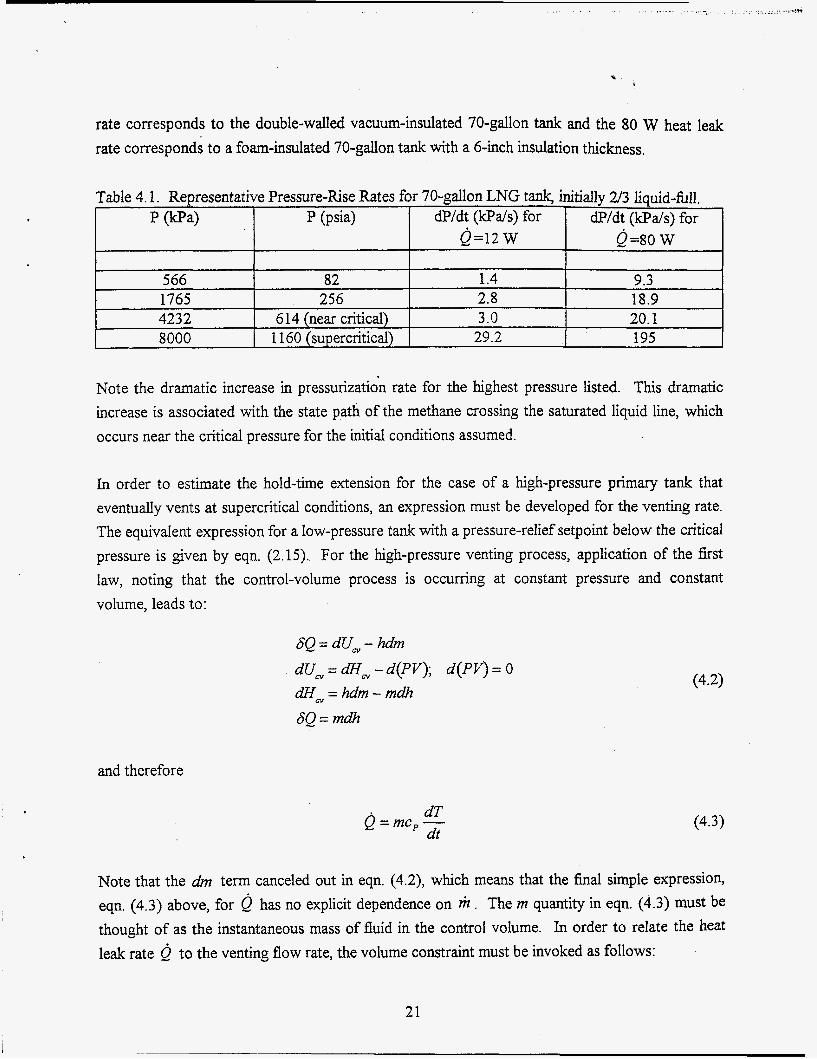
rate corresponds to the double-walled vacuum-insulated 70-gallon tank and the 80 W heat le& rate corresponds to a foam-insulated 70-gallon tank with a 6-inch insulation thickness.
p (@a) P (psia) dP/dt (kPa/s) for dP/dt (kpds) for Q=12 w &=so w
566 1765 423 2 8000
Note the dramatic increase in pressurization rate for the highest pressure listed. This dramatic increase is associated with the state path of the methane crossing the saturated liquid line, which occurs near the critical pressure for the initial conditions assumed.
82 1.4 9.3 256 2.8 18.9
614 (near critical) 3.0 20.1 1160 (supercritical) 29.2 195
In order to estimate the hold-time extension for the case of a high-pressure primary tank that eventually vents at supercritical conditions, an expression must be developed for the venting rate. The equivalent expression for a low-pressure tank with a pressure-relief setpoint below the critical pressure is given by eqn. (2.15). For the high-pressure venting process, application of the first law, noting that the control-volume process is occurring at constant pressure and constant volume, leads to:
SQ = dU, - hdm dU, = dH, - d(PV); d(PV) = 0 dH, = hdm - mdh SQ= rndh
and therefore
dT Q=mc,- dt (4.3)
Note that the dm term canceled out in eqn. (4.2), which means that the final simple expression, eqn. (4.3) above, for has no explicit dependence on r ) t . The m quantity in eqn. (4.3) must be thought of as the instantaneous mass of fluid in the control volume. In order to relate the heat leak rate Q to the venting flow rate, the volume constraint must be invoked as follows:
21

.... .-.- . . . . . . . . . I . . . . . .. ..
Qo
V =. mv = const
12 36 80
d( mv) = 0 = mdi + vdm
f i (kg/s)
V
1.98 x 10⁻⁵ 5.94 x 10⁻⁵ 1.32 x lo4
and therefore
k o u , = v 6 T
finally, substituting from eqn. (4.3) for (dT/dt) yields:
where
(4.4)
(4.5)
is the isobaric thermal expansion coefficient for the fluid, which is a state hnction that must be evaluated from property data at each state point of interest. The desired relationship between heat leak rate and venting flow rate for a super-critical fluid is provided by eqn. (4.6). Venting flow rates for methane venting in the super-critical region have been calculated using eqn. (4.6) as a hnction of heat leak rate. These values are listed in Table 4.2.
Table 4.2 Vent Flow Rates for Super-critical Methane r
Total hold times associated with allowing a foam-insulated primary tank to passively vent at a higher pressure to an uninsulated auxiliary tank have been estimated. Total hold times include pressurization time plus venting time. Pressurization time is the time required for the primary tank pressure to rise from an initial pressure (determined by the operating pressure of the tank) to a final venting pressure time during which the
determined by tank design and relief valve setpoint. Venting time is the primary tank is venting passively (no intermediate compressor) to the
22

auxiliary tank and the auxiliary tank pressure is rising fiom an initial pressure to the primary tank venting pressure. Results of the hold time calculations are listed in Table 4.3 as a knction of the primary-tank design pressure for an assumed initial pressure of 450 kPa (65 psia), primary and auxiliary tank volumes of 70 gallon (0.265 m3). In addition, a plot of tank pressures versus time for a PEgh value of 24.9 MPa is presented in Fig. 4.1. The plot shows the pressurization time and venting time for the primary tank and the pressurization of the auxiliary CNG tank.
The total hold times listed in Table 4.3 become quite acceptable for primary-tank pressures higher than about 3400 W a (493 psia). Furthermore, the hold-time values listed in Table 4.3 are conservative since they do not account for the reduced heat leak rate, which will occur as the primary tank pressure and temperature increase. For example, at 24900 H a , the primary tank temperature would be around 255 K, which'means that the driving temperature difference for heat leak would be significantly reduced compared to the low-pressure situation. In addition, to extend hold time even further, the vent gas could be exhausted fiom the primary tank via a coil surrounding the primary tank to further reduce the heat leak rate from the surroundings.
There are some serious drawbacks to this concept, however. In order to realize the hold times tabulated in Table 4.3 and in order to be able to refuel at low pressure, the vehicle must always be used for a long enough time that the pressures in both the auxiliary and primary tanks are reduced to the 450 W a level before the end of each duty cycle. Also in terms of economics, the material
25000
20000 P (kPa)
15000
10000
5000
0 0 50 100 150 200
t (hrs)
Figure 4.1. Tank pressures vs. time for 2-tank concept.
23

cost of the primary tank will increase almost linearly with pressure for higher pressure ratings since the required wall thickness is nearly a linear fbnction of pressure. Therefore the material
PEgh (kpa)
1700 3400 10000 24900
cost for a tank rated at 3000 psi would be approximately ten times the cost of a tank rated at 300
Pxgh (psia) Pressurization time Venting time Total Hold Time (hrS, Pi to &gh) (hrs, PA = phi&)
247 25 2.9 28 493 49 5.4 54 1450 59 34 93 3611 80 87 167
psi. Since material costs represent a major fraction of overall tank cost, the high-pressure concept may not result in cost savings, even if the cost of the auxiliary tank is not included.
The cases considered above indicate the necessity to consider the LNG tank as an integral part of the vehicle system rather than as a stand-alone component. Once this approach is adopted, a variety of additional possibilities are presented. Venting of methane vapor from a low-cost foam- insulated fuel tank is acceptable as long as there is something useful that can be done with the vapor. One concept to consider would be the usage of the methane boil-off in a fuel cell, which would serve to charge the vehicle batteries, which in turn, could provide power for the small compressor discussed above. Alternatively, the he1 cell could be used to charge a large bank of batteries as part of a hybrid vehicle concept.
4.2. Incorporation of a Phase-Change Thermal Energy Storage Material in a Non-Vacuum-Insulation System
Incorporation of a phase-change thermal energy storage material in a non-vacuum insulation system has also been considered. This hold-time-extension concept would involve incorporating a certain thickness of plastic-encapsulated phase-change material (PCM) into the insulation layer of a non-vacuum-insulated tank at an appropriate intermediate radius in order to reduce the heat leak rate to the inner tank. The value of the radius at which the PCM should be located depends on the melting point of the material. The melting point must always be higher than the temperature at which the cryogenic fuel is vented, otherwise it would not be possible to refreeze the material during venting and/or engine operation. If the melting point is close to, but somewhat higher than, the saturation temperature of methane at the set-point pressure of the pressure-relief valve (typically -1 11" C at 230 psig or 1.69 m a ) , the heat leak rate to the LNG can be reduced to very
24

, , . _ . .-- . I . . , . , . ..... ...., . . , ,,. .-.--- -c . . . ..
low values during the PCM thaw cycle, especially as the tank pressure approaches the venting pressure and the saturation temperature approaches the PCM melting point’temperature,
A schematic of an insulated tank with PCM is shown in Fig. 4.2 with a qualitative plot of temperature profiles for the two cases of PCM active and PCM inactive (thawed). Note that during the time period that the PCM is active, the temperature gradient between the PCM layer and the inner tank radius is very shallow, indicating the sigmficantly reduced heat leak rate to the LNG while the PCM is active, During this same time period, however, the heat leak rate into the PCM layer from the ambient is actually higher than when the PCM is inactive. When the PCM is
pcM\
foam insulation
LNG
TO
. TPCM TLNG
- - 4c.l- PCM inactive
- - - - - 1 1 1 I
r
- - - -
Figure 4.2 Schematic of insulation layer with phase-change material.
25
. . . . . . . . . . . . . . ., ., . . .. .._ ... .^_ . . . . . . . . . . . . . . , .. . .. .... ,.....,_....-k3 . . . .
fblly thawed, the "PCM inactive" profile occurs and the heat leak rate into the LNG increases dramatically. During vehicle operation, LNG drawn from the tank as either vapor or liquid flows through a coil imbedded in the PCM layer causing the PCM to refreeze. The PCM can also be refrozen during venting time periods.
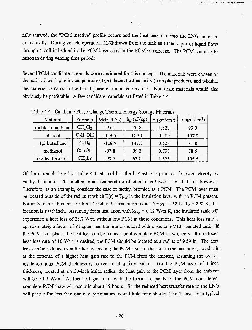
Several PCM candidate materials were considered for this concept. The materials were chosen on the basis of melting point temperature (Tw), latent heat capacity (high phif product), and whether the material remains in the liquid phase at room temperature. Non-toxic materials would also obviously be preferable. A few candidate materials are listed in Table 4.4.
Of the materials listed in Table 4.4, ethanol has the highest phif product, followed closely by methyl bromide. The melting point temperature of ethanol is lower than -111" C, however. Therefore, as an example, consider the case of methyl bromide as a PCM. The PCM layer must be located outside of the radius at which T(r) = T M ~ in the insulation layer with no PCM present. For an 8-inch-radius tank with a 14-inch outer insulation radius, TLNG = 162 K, To = 290 K, this location is r = 9 inch. Assuming foam insulation with kavg = 0.02 W/m K, the insulated tank will experience a heat loss of 28.7 W/m without any PCM at these conditions. This heat loss rate is approximately a factor of 8 higher than the rate associated with a vacuum/MLI-insulated tank. If the PCM is in place, the heat loss can be reduced until complete PCM thaw occurs. If a reduced heat loss rate of 10 W/m is desired, the PCM should be located at a radius of 9.59 in. The heat leak can be reduced even further by locating the PCM layer further out in the insulation, but this is at the expense of a higher heat gain rate to the PCM from the ambient, assuming the overall insulation plus PCM thickness is to remain at a fixed value. For the PCM layer of l-inch thickness, located at a 9.59-inch inside radius, the heat gain to the PCM layer from the ambient will be 54.9 W/m. At this heat gain rate, with the thermal capacity of the PCM considered, complete PCM thaw will occur in about 19 hours. So the reduced heat transfer rate to the LNG will persist for less than one day, yielding an overall hold time shorter than 2 days for a typical
26

. . . . - .--..A
bus-sized tank. Greater thicknesses of PCM and greater outer insulation thicknesses were &O
considered.
Another issue to be considered with this concept is the time period of vehicle operation that must occur in order to refreeze the PCM after it has hlly thawed. This time may be estimated by considering the heat transfer from the cold he1 (liquid or vapor) to the PCM. The actual transient heat transfer problem with phase change, which must be solved to accurately predict the freeze time is quite complex, but an approximate time may be obtained from the following:
or
mmGcP ATt = mpW hf = (pV>,,, h,
(4.9)
where hif is the enthalpy of fusion for the PCM and cp is the specific heat of the liquid fuel. The temperature difference AT -between the LNG fuel at its operating pressure and temperature and the melting point temperature of the PCM can be determined as follows. For LNG firel at a typical operating pressure of 650 H a , the saturation temperature is 141 K. For the case of methyl bromide, the melting point temperature of the PCM is 162 K. Therefore the maximum driving temperature difference for heat transfer between the fuel and the PCM is 21 K. If a typical fuel flow rate is assumed to be 4.6 x 10⁻³ kg/s (see section 2.3), and using values of density, p, and h s listed in Table 4.4, a refreeze time of 6.6 hrs is predicted. Actual refieeze times would be somewhat longer since heat gain from the surroundings during refreeze has been neglected and since the actual average driving temperature difference for heat transfer from the PCM to the LNG fuel will be smaller than 21 K.
The overall conclusion is that the phase-change thermal energy storage concept has some merit, but that the combination of conventional non-vacuum insulation plus PCM still provides a significantly shorter hold time than vacuum/MLI systems. The cost of implementing the PCM concept may also be significant.
27
.. .
5.0 Alternative Tank Materials
5.1 Composite Materials for Cryogenic Tanks
The concept of utilizing an LNG tank fabricated fiom composite materials was investigated. Currently, LNG tanks are made fiom stainless steel or aluminum depending on the application. However, several companies involved in the composites industry have looked into developing LNG tanks. They are eager to develop and produce a composite tank for LNG but they have not procured the project development finding. Project development funding is required to overcome several obstacles.
1. As the LNG fuel is consumed the temperature of certain portions of the tank increases. Potentially, the tank could experience a temperature cycle greater than 300°F. This thermal cycling causes at least two problems. First, the resin can crack and strength of the tank will decrease. Composite LNG tanks will have shorter lifetimes when compared to the standard stainless steel LNG tanks.
_ _ A graphite epoxy composite tank successklly underwent simulated flight testing on the DC-XA rocket. The composite tank did not leak its liquid hydrogen contents. It is not clear if resin cracking would eventually be a problem for this tank. In this example the composite tank would be thoroughly inspected before its next trip. It is unlikely that a consumer would inspect their fuel tank before each fill up.
Second, thermal expansion problems are produced at penetration points. A seal must be placed at each penetration point. The seals can have composite, metal, andor plastic components. Each material will have a distinct coefficient of thermal expansion. Throughout the temperature cycle each component will expand or contract at a different rate. It is dficult to design a seal that remains effective as its components expand and contract at different rates.
2. The composite tank configuration must be different from the double walled stainless steel LNG tank design. The inner tank could be formed of composite material, The difficulty lies in creating the insulating gap between the tank walls. A composite must be formed around a mandrel or a mold. It is not possible to form a composite around air. A single-piece outer tank could not be formed around the inner tank and air gap. This is not an exclusive reason for abandoning the composite LNG tank concept. The tank design could be modified to allow a completely composite tank. The inner tank could be vapor-shielded and then insulated with a stiff foam
28

insulation. M e r the insulation had set up the outer tank could be wrapped around it. Alternately, the inner tank could be made of aluminum. Then a vapor jacket and insulation could be placed around the aluminum tank. The outer tank could be a composite. Engineers at Thiokol are optimistic that there is a good chance of developing a similar tank for low cost.
3. If the
development costs are transferred to a single tank it will likely cancel out any benefit (such as weight reduction) gained by using a composite tank. Ifthis cost is split between 50 to 100 tanks it may not be prohibitive. Amalga Composites estimated the tooling costs for a single wall cylindrical tank with hemispherical ends would be several thousand dollars.
High design and tooling expenses will be incurred by a small production run.
A search of possible suppliers of composite tanks was performed. This search turned up several companies that might be able to supply a composite tank for LNG. These manufacturers are listed below.
Tankinetics: Chuck Hoffman 1-800-624-2698 50 1-741-3580
_ - ASME Section 10 (class I and 11) certified fiberglass tanks
maximum pressure 150 psi fiberglass tanks used for flammable gasoline (likely ok for LNG) up to 125 R diameter
-65F to 150F
Amalga Composites Mike Hable 1-800-394-9545 414-453 -9555 filament wound composite tubes for cryogenics strength increases at lower temperatures (slow down resin molecule motion) tooling several thousand dollars
(they are looking into the best manufacturing method for small run and the temperature cycling concerns but felt they could make a workable composite tank)
Taylor Wharton 3 3 4-443 -8680 make LNG vehicle tanks (specific to each vehicle) 304 SS 100+ tank production volumes to be cost effective did not feel that a double wall tank was feasible from the production point of view
,
29

. . . . ._ ..._.__ . . , .... .. . . .. . .
. Thiokol Corporation
Larry Johnson 801-863-8942 Mike Blair (marketing manager) Currently:
* high pressure storage of CNG in composite tanks * propane tanks for Chrysler vehicle square design (common walls for cylindrical tanks) hold 30 gal (-$2300) and -70 gal (-3000) 5083 Al
Thiokol is considering converting their 70 gal aluminum propane tank to an LNG tank. Aluminum 5083 can be used for LNG storage with an added outside liner and insulation. Of course, costs will decrease as production increases but no cost estimates were given for converting the propane tank to LNG. Thiokol has also spent more fime on the idea of using composite materials for LNG tanks than any other company (or at least they were the most willing to consider the concept of a composite LNG tank). They were concerned about the temperature cycling, cracking resin, and CTE problems. It sounded like they would initially use the aluminum tank as an inner tank, add an insulation space, and a composite exterior before they would develop a solely composite LNG tank. This would reduce development and tooling costs because half of the tank is already designed and tooled.
5.2 Aluminum Vs Stainless Steel for Cryogenic Tanks
In this section, properties of aluminum and stainless steel are compared and the most suitable material for the cryogenic tank is recommended. Several cryogenic tank manufacturers have been contacted, and as mentioned earlier, all current tanks are double-walled vacuum-insulated with multi layer insulation (MLI). For smaller tanks (on board vehicles), the tank is fabricated from double-walled stainless steel inner and outer tanks. The very small tanks, one- to five-gallon laboratory “jugs,” are fabricated from double-walled aluminum. For very large tanks, over 5000 gallons, the inner tank is fabricated from stainless steel and the outer tank from carbon steel. It should be mentioned that, for space applications, more cryogenic tanks are fabricated from aluminum than stainless steel since aluminum is much lighter than stainless steel. Aluminum and stainless steel tanks are fabricated from sheets of material that are rolled and then welded. Tables 5.1 and 5.2, respectively, provide information related to sizes and price of both candidates.
. I
30

. . . ..... ... ..... /.”
Table 5.1 Stainless steel sizes
The mechanical, physical, and thermal properties of both metals are readily available in any strength-of-materials textbook or mechanical engineering handbook. M e r studying these properties and consulting with material science experts at INEEL, we believe that stainless steel is a better candidate to use in a cryogenic environment.
A summary of the advantages of stainless steel over aluminum is presented below:
1) better mechanical properties 2) ease of fabrication (austenitic stainless steel would not need a post-weld heat treatment to restore properties, 6061 T-6 would) 3) better ductility (as welded 6061 T-6 is 4% at -253C, where 304L stainless steel is 33%)
31

4) better fiacture mechanical properties at cryogenic temperatures (Le., the critical stress intensity factor for 6061 T-6 is 37.9 ksi(in)'" at -196C, while it is 236 ksi(in)l/2 for austenitic stainless steel at -253C).
6.0 Use of Hydrates for LNG Fuel Storage
The usage of water-methane hydrates as a form of fuel storage for liquid natural gas was also investigated. The potential advantage of this technique is that fuel storage temperatures could be much higher than for pure LNG, thereby possibly eliminating the need for a vacuum-insulated fuel tank.
Water-methane hydrates exist as a dodecahedral (twelve-faced) cell having hydrogen or oxygen atoms of the water molecules at the vertices and a trapped methane molecule in the interior. In the theoretical maximum concentration there are six water molecules per methane molecule. Natural hydrates are known to be stable at ocean depths greater than 300 m (pressures > 3.02 MPa or 425 psi, temperatures near 0" C), though experiments at lower temperatures have shown the hydrates to be stable at lower pressures. In the hydration process, solid-phase ice-like hydrates are formed by contact of natural gas and water at temperatures above the freezing point of pure water up to 60 F and at pressures from 380 to 2000 psig.
The possibility of utilizing this process for vehicle fuel storage was investigated. Adding a small amount of propane (approximately 1 percent) improves the pressure and temperature requirements for formation of hydrates, increasing the storage quantity of fuel in the fuel tank and improves fuel storage capability in the fuel tank at lower pressures.
Disassociation of natural gas from the hydrate is achieved by increasing the temperature of the solid hydrate by circulating waste heat from the engine, causing a controlled pressure drop. Free excess natural gas in the tank during and after completion of the hydrate formation process is used to start and run the engine during warm-up.
6.1 Advantages of the Use of Hydrates
Hydrates are solids that can be stored at moderate pressure (about 50 psi) and at temperatures (about 10 F) at which conventional insulating materials, such as perlite or foam, are sufficient. These conditions contrast with CNG, which is stored at room temperature, but at pressure of
32

.
. . .., ,.. _.....
3600 psi or LNG, which is stored at moderate pressure 200 psi, but at temperatures of -260° to - 200" F.
In addition, the methane is released slowly when the hydrate is exposed to air. Thus failue of the storage tank or piping does not result in a catastrophic release of methane into the atmosphere. The crystalline structure of water surrounding the gas in the solid phase stabilizes the gas while on-board and makes it safer for transportation. Accordingly, if the pressure is suddenly reduced, the natural gas will still be slowly released fiom solid hydrate at a controlled rate. Natural gas encased in ice in storage makes natural gas more acceptable to consumers because of the added safety. Release of the methane is slow.
6.2 Disadvantages of the Use of Hydrates
Methane hydrates contain only about one sixth the energy density of diesel &el. The hydrate weight of a 200 gallon diesel-equivalent tank is about 9200 pounds. Correspondingly, the hydrate weight for a 15 gallon gasoline-equivalent tank would be 625 pounds, imposing a' sigmficant penalty in the loss of usable cargo capacity. This penalty may be acceptable for stationary storage applications, but is unacceptable for vehicle applications. The use of hydrates as a storage medium for locomotive fuel may suffer less from the weight penalty.
7.0 Summary and Conclusions
This report is the result of a study, which was performed at the Idaho National Engineering and Environmental Laboratory (INEEL), under contract with the Gas Research Institute (GRI). The objective of this study was to investigate development of a low-cost (capital and maintenance) LNG vehicle fuel storage tank with low fuel boil-off, low tank pressure, and high safety margin. These objectives are driven by the fact that one of the largest contributors to the cost of converting a vehicle to LNG is the cost of the LNG fuel tank. To minimize heat leak from the surroundings into the low-temperature fuel, these tanks are designed as cryogenic dewars with double walls and an evacuated insulation space containing multi-layer insulation. The primary focus of the analysis was to try to devise a fuel tank concept that allowed for the elimination of the double-wall requirement. Thermodynamic relations were developed for analyzing the fuel tank transient response to heat transfer, venting of vapor, and out-flow of either vapor or liquid. A review of vacuum and non-vacuum insulation systems was performed and case studies were presented. Several hold-time-extension concepts were considered conventional non-evacuated insulation, the use of a phase-change thermal
including the use of energy storage material
33

imbedded in a conventional insulation layer, and the use of an auxiliary storage tank to accept the boil-off fiom the primary fuel tank. Consideration was also given to the possibility of using alternate materials such as aluminum or composites for tank fabrication.
Results of this study have validated the benefit of vacuum/MLI insulation for LNG &el tanks and the difficulty in identifLing viable alternatives. The thickness of a non-vacuum insulation layer would have to be unreasonably large to achieve an acceptable non-venting hold time. Reasonable hold times could be achieved by using an auxiliary tank to accept boil-off vapor from a non- vacuum insulated primary tank, if the vapor in the auxiliary tank can be stored at high pressure. High pressure can be realized in the auxiliary tank either through the use of a small compressor located between the primary and auxiliary tanks or by allowing the primary tank to achieve a high pressure prior to venting. The first option is expensive and the second option is inconsistent with one of the primary objectives of the study, which is to develop a low-cost LNG fuel tank while maintaining low-pressure. The effect of incorporation of a reasonable thickness of phase-change material into the thickness of an LNG-tank insulation layer was analyzed. A hold-time extension of approximately one day is achievable, assuming the phase-change material is hlly fiozen at the onset of venting. Refreezing of the phase-change material requires approximately 6 hrs. of engine operation. With regard to alternate tank materials, stainless steel is preferable to aluminum due to its superior low-temperature properties. The usage of composite materials for cryogenic fuel storage is a current research topic. Several problems must be addressed before it can be considered.
34

. ..
References
( 1) W A 57 Standard for Liquefied Natural Gas (LNG) Vehicular Fuel Systems, NFPA 1996.
( 2) Hibl, J. J., "Cryogenic Fuel Systems for Motor Vehicles," Achtances in Cryogenic Engineering, Vol. 21, 1975, pp. 180-186. 7
( 3) Lin, C. S., Van Dresar, N. T., and Hasa, M. M., "A Pressure Control Analysis of Cryogenic 8 Storage Systems," NASA TM 104409, June, 1991.
( 4) Ripling, E. J., Crosley, P. B., and Geiger, R. J., "A Suggested Method for Evaluating the Safety and Durability of Vehicle LNG Containment Systems," GRI Report No. GRI- 94/0002, May 1994.
( 5) Jennings, F. A., and Studhalter, W. R.; "Natural Gas Fuel Tanks for Automobiles: Safety Problems," ASME Paper No. 71-PVP-62, May, 1971.
( 6) Bratvold, D., Friedman, D., Chernoff, H., Farhondehpay, D., and Comay, C., "Introduction to LNG Vehicle Safety," GRI Report No. GRI-92/0465, March, 1994.
( 7) Loper, G. A., and Davis, D. M., "Liquefied Natural Gas Conversion of a GMC Truck," SAE Special Publication no. 894, pp. 167-173, 1992.
( 8) Liss, W. E., Okazaki, S., Acker, G. H., and Moulton, D. S., "Fuel Issues for Liquefied Natural Gas Vehicles," SAE Technical Paper 922360, 1992.
( 9) Constable, G. A., Gibson, C. J., and Gram, A., YJse of LNG in Heavy-Duty Vehicles," S A E Technical Paper No. 891670, August, 1989.
(10) Acker, G. H., and Moulton, S, "LNG Weathering Effects - Theoretical and Empirical," GRI Technical Report No. GRI-92/0464, Topical Report GETA 92-02, December, 1992.
(1 1) McIntosh, G. E., Leonard, K. R., Bliss, T.D., "LNG Tank for Heavy Duty Trucks," presented at the Cryogenic Engineering Conference, Portland, 1997.
35
M98052559 IllllllllIIIlllllllllllllllllllllllll%1lllllIll1lll1
Report Number
Publ. Date (11) E- ,i N= Sponsor Code (18) -
UC Category (1 9) uc-ycn ,o o€ IER
DOE