
ID3D-R - rfidaccesscontrol.comrfidaccesscontrol.com/images/Biometrics/SCHLAGE... · This Class A...
62
i Terminal User’s Guide ID3D-R
Transcript of ID3D-R - rfidaccesscontrol.comrfidaccesscontrol.com/images/Biometrics/SCHLAGE... · This Class A...

i
Terminal User’s GuideID3D-R

ii
Table of Contents1.0 Introduction ...................................................................................................................... 11.1 About the Manual .............................................................................................................. 11.2 ID3D-R General Description .............................................................................................. 11.3 Specifications .................................................................................................................... 2
2.0 Unpacking ........................................................................................................................ 52.1 Inspection .......................................................................................................................... 52.2 List of Materials ................................................................................................................. 52.3 Enclosure Key .................................................................................................................... 52.4 Bench Check ..................................................................................................................... 5
3.0 ID3D-R HandKey Functional Capabilities ...................................................................... 73.1 Identity Verification ............................................................................................................. 73.2 The ID3D-R HandKey ........................................................................................................ 73.3 ID3D-R HandKey Functional Capabilities .......................................................................... 83.3.1 Operating Modes ............................................................................................................ 83.3.2 ID Number Entry ............................................................................................................. 93.3.3 Keypad ID Entry ............................................................................................................. 93.3.4 Card Reader ID Entry ..................................................................................................... 93.3.5 Card Reader Emulation .................................................................................................. 93.3.6 Duress Code ................................................................................................................... 93.3.7 Time and Attendance Code .......................................................................................... 103.3.8 Time Zones ................................................................................................................... 103.3.9 Host System Interface .................................................................................................. 113.3.10 Status Monitoring ....................................................................................................... 113.3.11 Door and Auxiliary Circuit Control .............................................................................. 123.3.12 Serial I/O Channels .................................................................................................... 123.4 Memory Capacity ............................................................................................................ 12
4.0 Installation ...................................................................................................................... 134.1 Mechanical Installation .................................................................................................... 134.1.1 Table Top Installation .................................................................................................... 134.1.2 Wall Mount Installation .................................................................................................. 144.2 Electrical Installation ........................................................................................................ 144.2.1 Power Connections ....................................................................................................... 154.2.2 Door Status Switch Wiring ............................................................................................ 164.2.3 Request to Exit Switch Wiring ...................................................................................... 164.2.4 Auxiliary Alarm Monitor Wiring ..................................................................................... 164.2.5 Lock Wiring ................................................................................................................... 164.2.6 Auxiliary Control Circuit Wiring ..................................................................................... 164.2.7 RS-485/422 Network Wiring ......................................................................................... 174.2.8 Card Access System Interface ..................................................................................... 174.2.9 Printer Connection ........................................................................................................ 184.3 Serial Channel Dip Switch Settings ................................................................................. 184.4 System Turn-On ............................................................................................................... 18

ID3D-R Manual
iii
5.0 Operation-Access Control Mode .................................................................................. 215.1 Using the Hand Reader to Gain Access .......................................................................... 215.2 Ready Display ................................................................................................................. 225.3 Central Printer ................................................................................................................. 22
6.0 System Operation-Command Mode ............................................................................. 236.1 Command Mode Overview .............................................................................................. 236.2 Important Background Information .................................................................................. 246.2.1 Passwords and Authority Levels ................................................................................... 246.3 Entering and Exiting the Command Mode ....................................................................... 256.4 Set User Data .................................................................................................................. 256.4.1 Set User’s Data............................................................................................................. 266.4.1.1 Set User Authority Level ............................................................................................ 266.4.1.2 Set User’s Reject Level.............................................................................................. 266.4.1.3 Set User’s Time Zone ................................................................................................ 276.4.2 Time Zone and Holiday Table Commands .................................................................... 276.4.2.1 Editing the TIme Zone Table ...................................................................................... 276.4.2.2 Printing the Time Zone Table ..................................................................................... 286.4.2.3 Clearing the Time Zone Table .................................................................................... 286.4.2.4 Editing the Holiday Table ........................................................................................... 286.4.2.5 Printing the Holiday Table .......................................................................................... 286.4.2.6 Clearing the Holiday Table ......................................................................................... 286.4.2.7 Setting the Time Zone for Auto Unlock ...................................................................... 286.4.3 Set Identity Reject Threshold........................................................................................ 296.4.4 Set Passwords .............................................................................................................. 296.4.5 Clear All Hand Data ...................................................................................................... 296.4.6 Create “No Handread” ID Number ................................................................................ 306.5 Enrollment Group Commands ......................................................................................... 306.5.1 Enrolling a User ............................................................................................................ 306.5.2 Remove User ................................................................................................................ 316.6 Management Group Commands ..................................................................................... 326.6.1 Set Time and Date ........................................................................................................ 326.6.2 List User Information .................................................................................................... 326.6.3 Send Data to Network .................................................................................................. 326.6.4 Receive Data From Network ......................................................................................... 326.7 Setup Group Commands ................................................................................................. 336.7.1 Set Print Options .......................................................................................................... 336.7.2 Set ID Mode .................................................................................................................. 336.7.2.1 ID Length ................................................................................................................... 336.7.2.2 Set T&A Mode (Time and Attendance) ...................................................................... 336.7.2.3 Set Duress Code Mode ............................................................................................. 346.7.3 Set Reader Mode ......................................................................................................... 346.7.4 Set Output Mode .......................................................................................................... 356.7.5 Set Lock/Shunt Time .................................................................................................... 356.7.6 Auxiliary Output Setup .................................................................................................. 356.7.7 Set Site Code ............................................................................................................... 366.7.8 Set Serial Baud Rate .................................................................................................... 36
iv
6.7.9 Set Beeper Mode .......................................................................................................... 366.8 Service Group Commands .............................................................................................. 366.8.1 Check and Calibrate ..................................................................................................... 376.8.2 System Status Display .................................................................................................. 376.8.3 Network Status ............................................................................................................. 38
7.0 Maintenence ................................................................................................................... 397.1 Cleaning .......................................................................................................................... 397.2 Top Panel Removal .......................................................................................................... 397.3 Setup and Hand Memory Reset ...................................................................................... 397.4 Memory Battery Replacement ......................................................................................... 407.5 Output Circuit Driver Replacement .................................................................................. 407.6 Serial Channel Driver Replacement ................................................................................ 407.7 Power Converter Replacement ........................................................................................ 417.8 Prom Chip Replacement ................................................................................................. 41
Appendix D ........................................................................................................................... 42
Index ..................................................................................................................................... 53

ID3D-R Manual
v
LIMITED WARRANTY
Schlage Biometrics, Inc. (the “Company”) warrants to the original user the products manufactured by the Company (the “Product”) to be free of defects in material and workmanship for a period of one year from the date of purchase by such user or 15 months from the date of shipment from the factory, whichever is sooner, provided:
1. The Company has been notified within such period by return of any alleged defective product, free and clear of all liens and encumbrances, to the Company or its authorized dealer, transportation prepaid; and
2. The Product has not been abused, misused or improperly maintained and/or repaired during such period; and
3. Such defect has not been caused by ordinary wear and tear; and
4. Such defect is not the result of voltage surges/brownouts, lightning, water damage/flooding, fire, explosion, earthquakes, tornadoes, acts of aggression/war or similar phenomenon; and
5. Accessories used as integral to the Product have been approved by the Company.
The Company shall, at its option, either repair or replace, free of charge, the Product found, upon the Company’s inspection, to be so defective, or if agreed upon, refund the purchase price, less a reasonable allowance for depreciation, in exchange for the Product.
THE COMPANY MAKES NO OTHER WARRANTY AND ALL IMPLIED WARRANTIES INCLUDING ANY WARRANTY OF MERCHANTABILITY OR FITNESS FOR A PARTICULAR PURPOSE ARE LIMITED TO THE DURATION OF THE EXPRESSED WARRANTY PERIOD AS SET FORTH ABOVE.
THE COMPANY’S MAXIMUM LIABILITY THEREUNDER IS LIMITED TO THE PURCHASE PRICE OF THE PRODUCT, IN NO EVENT SHALL THE COMPANY BE LIABLE FOR ANY CONSEQUENTIAL, INDIRECT, INCIDENTAL OR SPECIAL DAMAGES OF ANY NATURE ARISING FROM THE SAME OR THE USE OF THE PRODUCT.
Schlage Biometrics reserves the right to make changes in the design of any of its products without incurring any obligation to make the same change on units previously purchased.
Note: This equipment has been tested and found to comply with the limits for a Class A digital device, pursuant to part 15 of the FCC Rules. These limits are designed to provide reasonable protection against harmful interference when the equipment is operated in a commercial environment. This equipment generates, uses, and can radiate radio frequency energy and, if not installed and used in accordance with the instruction manual, may cause harmful interference to radio communicatins. Operation of this equipment in a residential area is likely to cause harmful interference in which case the user will be required to correct the interference at his own expense.
This Class A digital apparatus meets all requirements of the Canadian Interference-Causing Equipment Regulations.
Cet appareil de la classe A respecte touts les exigences du Reglement sur le materiel brouilleur du Canada.

vi

1
1.0 Introduction1.1 About the Manual
This manual describes the function, installation, operation, and maintenance of the ID3D-R HandKey Three Dimensional Hand Geometry identity verifier, and the IS-400 Power Supply. It provides important information for the user, installer, and security system designer. This manual applies to E6 Versions and later of the HandKey firmware. This version includes significant functional enhancements over earlier versions.
Before attempting to operate the unit, please review at least sections five and six.
1.2 ID3D-R General Description
The ID3D-R HandKey is the latest in Schlage Biometrics’ line of Hand Geometry Biometric Identifiers. The ID3D-R can be operated as a complete stand-alone access control station or it can be networked with other HandKeys to provide a simple network of biometric identity verification stations with centralized enrollment and event recording or it can be used to a PC and Schlage Biometrics HandNet software package to provide a complete centrally controlled system. A completely specified communications protocol for the ID3D-R is provided so that connections to a host computer is simply a matter of proper host software configuration.
Whether used stand-alone or networked, the ID3D-R will control a lock and auxiliary alarm signalling circuit directly, or can be configured to provide verified code data output in emulation of standard Wiegand or Magnetic Stripe card readers. The availability of this card reader emulation output enables the hand reader to be connected directly into standard card type access control systems.
When used as a stand-alone access control station, the ID3D-R provides RS-232 output to a standard serial type printer. All system activity can be printed. Each printed line shows the time, date, location, activity, and users ID number where applicable.
When used in a networked configuration, up to 31 Access Control Hand Readers can be connected to a central Enrollment Reader or host computer using a two wire RS-485 network or a four wire RS-422 network of up to 4,000 feet in length. The card reader emulation capability of the ID3D-R can also be used to integrate the HandKey into an existing Wiegand or Magnetic Stripe card access control system with no change required to the existing system hardware or software.
When an ID3D-R network is used without a host computer, the ID3D-R as an enrollment reader (master unit), must be used to enroll new users on to the system and remove users. The enrollment reader has the capability to broadcast enrollment data to allother hand readers on the network. There may be only one enrollment reader per network. When used as the network enrollment reader, the ID3D-R still maintains its capability to act as an access control station, verifying identity, controlling a door lock and emulating a card reader.

1.0 Introduction
2
ID3D-R’s also serve as the network access control remote readers. There may be up to 32 remote readers installed per network. The remote readers receive user enrollment data from the network master, verifies user identity each time a user ID is entered via the keypad or card reader, and transmits the verified card or keypad data to an optional host access control system via the card reader emulation output port. The controlled door lock may be operated directly by the ID3D-R if card reader emulation is not used, or from the optional host sytem.
ID numbers may be entered either using the built-in keypad, or Magnetic Stripe or Wiegand card readers. ID numbers may be up to ten digits long. Wiegand and Magnetic Stripe card reader emulation outputs are provided so that interface with many existing access control systems is simply a matter of connecting the hand reader in place of a card reader. ID length may be limited by Wiegand format when using the Wiegand interface.
In addition to entering the user’s ID number from the keypad, the HandKey can also be programmed to request an account code. This account code wil then be data logged along with the ID number and may be used in time and attendance and labor tracking applications.
The HandKey has the capability to control access by time as well as users ID number. 62 programmable time zones (1-60) are available for assignment to users. Special time zones may be assigned to holidays. The lock and auxiliary control outputs can be programmed to operate by time zone as well.
A duress code mode of operation may be set. With this mode, the entry of a programmed “duress digit” will cause an alarm. This feature provides a useful method for creating an alarm if the user is being forced to operate the HandKey.
Alarm monitoring capability is provided for a door switch, an auxiliary alarm monitoring circuit, and tamper. An auxiliary output control circuit can be programmed to activate in response to any combination of the above alarms, as well as in response to invalid access attempts or a duress code entry from the keypad. This auxiliary output can be used to control local or remote alarm enunciators.
The ID3D-R has a standard internal memory capacity for 256 users. An expanded memory version of 3,328 or 9,728, or 27,904 users are also available. An internal lithium battery provides five years of memory retention for hand template and system setup data.
The ID3D-R HandKey can be table or wall mounted. An optional wall mount kit facilitates either flush or recessed wall mounting.
1.3 Specifications
SPECIFICATIONSID3D-R HANDKEY
POWER REQUIREMENTS:
Input Voltage............12 to 14 VDC. Input Current............0.450 Amps Min. -0.5 Amps Max. Input Power...............7 Watts Max.
LOCK and AUXILIARY:
Switched 12 VDC at 0.1 Amp maximum for operating a control relay or low current actuation device. Schlage Biometrics recommends the use of an isolation relay for this application.

ID3D-R Manual
3
ALARM MONITORING CIRCUITS:
Door switch, auxiliary input circuit, and tamper. 0.5 Ma. current loops. Breaking circuit produces alarm.
COMMUNICATION PORTS:
Two serial ports:
CH-0................RS-422 or RS-485 CH-1................RS-232 (Printer only)
IDENTIFICATION NUMBER INPUT DEVICE:
A keypad for ID number entry is built in. Wiegand and Magnetic Stripe card reader input are also available.
ID NUMBER SIZE:
ID numbers may be one to ten digits in length.
WIEGAND OUTPUT:
Wiegand compatible output is available for host system interface. Upon verification of identity, the entered ID number along with the site code, is transmitted in 26 bit Wiegand with eight bit site code format to the optional Wiegand compatible host. Other formats and Magnetic Stripe (ABA/ANSI track two) compatible outputs are also available in a +5 VDC = data high or a 0VDC = data high format.
STANDARD WIEGAND FORMAT:
A 26 bit Wiegand format is standard. The first bit transmitted or received is even parity over the next 12 bits. The last bit is odd parity over the preceding 12 bits. The second through ninth bits are the assigned facility code with the second bit most significant. The tenth through twenty-fifth bits are the ID number entered at the keypad, with the tenth bit most significant. The card reader emulation port transmits Wiegand data with a pulse width of 100 microseconds and an interpulse period of 1,200 microseconds. Other code formats can easily be accommodated, but the factory must be consulted first.
MEMORY CAPACITY:
Memory is available to store hand data for a minimum of 256 users. This is expandable to 3,328 or 9,728 or 27,904 users. Transaction data log buffering is also available for networked systems. Up to 3,405 transactions are buffered in a fifo buffer until transmission of stored data is requested by the host computer.
REQUEST TO EXIT INPUT:
A request to exit switch or keypad (KP-103) may be connected for secure side exit.
HANDKEY SIZE:
6.50 in. (16.5 cm) wide 8.38 in. (21.3 cm) high 7.38 in. (18.7 cm) deep
OPERATING TEMPERATURE:
32 to 110 F. limited by platen temperature.

1.0 Introduction
4
RELATIVE HUMIDITY:
95% Max. non-condensing.
HAND READ AND VERIFICATION TIME:
Less than two seconds.
THROUGHPUT:
15 per minute.
VERIFICATION THRESHOLD:
User programmable on system and individual user basis.
AUXILIARY ALARM CONDITIONS:
User programmable.

5
2.0 Unpacking2.1 Inspection
Carefully unpack the ID3D-R. Remove protective packing material and inspect each item for damage. Report any damage to the carrier and to Schlage Biometrics, Inc. Retain the container and packing material for use in transporting the equipment to the job site.
2.2 List of Materials
The ID3D-R Hand Reader shipping container should contain:
1 ea. ID3D-R hand reader assembly
1 ea. ID3D-R installation and operating manual
1 ea. Enclosure key envelope
The IS-400 hand reader power unit shipping container should contain:
1 ea. IS-400 power supply
The WM-200 wall mount kit shipping container should contain:
1 ea. wall mount enclosure assembly
1 ea. enclosure key envelope
2.3 Enclosure Key
Shipped with each hand reader or wall mount kit is an envelope containing the key which unlocks the enclosure. This envelope must only be opened by a person authorized and cleared to do so.
2.4 Bench Check
Upon completion of the unpacking, it is useful to connect the hand reader and test its operation. The only connections required for an operational test are two wires to the power supply. These connections are made to the ID3D-R terminal strip as per the wiring diagram in Appendix “D” of this manual. The hand reader can then be turned on and tested by verifying that it operates in accordance with the operating instructions.
Before applying power, be sure that the correct power supply voltage will be applied and that the power supply polarity is correct. Otherwise, serious damage may result. Refer to the connection diagrams at the rear of this manual for proper hook-up.
When first powering up the hand reader, the camera exposure is automatically set. In order for this to function properly, be sure that the platen and mirrors are clean and free of foreign objects. The hand reader is ready for operation when the front panel display shows.
**IMPORTANT**

2.0 Unpacking
6
**READY**
Remember that any changes to the system setup made using the command mode will be permanently stored. Particular care should be taken if passwords are changed as it is possible to lock oneself out of the command mode if a password is forgotten. If this happens, consult Section 7 of this manual for memory reset instructions.
During bench check is a good time to review the operating instructions, performing each operations as it is described.

7
3.0 ID3D-R HandKey Functional Capabilities3.1 Identity Verification
There is a fundamental rule of access control that is often overlooked.
CARD READERS CANNOT IDENTIFY PEOPLE,neither canKEYPADS
PIN CODESBRASS KEYSDOCUMENTS
PEOPLE CAN IDENTIFY PEOPLE.DOGS CAN IDENTIFY PEOPLE.
BIOMETRICS CAN IDENTIFY PEOPLE.
And Biometrics does it best!!!
Biometric access control has brought a new dimension to access control security systems. Biometric access control devices use key characteristics such as hand geometry that are unique to the individual. For the first time true automatic access control is possible. With hand geometry, it is the authorized person who is granted access, not merely the keyholder.
3.2 The ID3D-R HandKey
The ID3D-R is a biometric identification device that uses a three-dimensional image of the hand to uniquely verify a person’s identity. This image is acquired by a television-like camera. The system is small, simple, quick, and uses no moving parts.
The ID3D-R contains a digital camera which records an image of the hand, and a microprocessor which extracts identity discriminating characteristics from the hand image. During the inital enrollment process three hand measurements are made and the results averaged. This forms a template of the user’s hand which is stored for later use in identity verification. The stored template is automatically updated with each successful use. This assures that changes in the hand that occur over a period of time are accommodated for.
To use the system, the enrolled user enters an ID number via a keypad or by presenting a standard access control card. The system prompts for the hand to be placed on the measuring surface (platen), and once the hand is detected to be properly positioned, takes a TV-like picture. The identity discriminating characteristics are extracted from the picture and compared to the previously stored template. The results of the comparison are displayed, in the form of a score, in about a second. The results can be used to operate an access control device, such as a door lock, or to signal a higher level system device that identity has been verified or rejected.

3.0 ID3D-R HandKey Functional Capabilities
8
3.3 ID3D-R HandKey Functional Capabilities
The ID3D-R HandKey hand reader provides-in one compact, low cost package-fast and accurate biometric identification and access control. It can store up to 27,904 nine-byte hand templates locally. It has lock and auxiliary control outputs, and alarm monitoring input circuits. A HandKey can control access by time as well as by individual users. Communication ports provide for audit trail information and networked system operation. The HandKey has a local keypad for PIN entry and can accept ID information from most commonly used card readers as well as from a host computer. System management functions are all controllable from the front panel of the hand reader, or by central host computer.
3.3.1 Operating Modes
The ID3D-R HandKey can be operated as a stand-alone access control station, as a network master enrollment station or as a networked access control station which receives and processes commands from a network host or a master unit. Operating mode selection is made by menu selections using the hand reader keypad.
When operated as a stand-alone access control station the ID3D-R provides complete capability for access control of a single door. In addition to controlling the door lock, it will also monitor door status and auxiliary alarm switches and signal a local or remote alarm enunciator. It datalogs all activity to a serial printer. Users can be enrolled or removed from the system without the need for an additional programmer or enrollment unit.
When used as a networked access control station, the ID3D-R can be controlled by the network master in a wide variety of ways. The network master may be a host computer or another HandKey. Communication between the networked hand readers and the host is via RS-485 or RS-422 data link. This data lnk may extend up to 4,000 feet, and up to 31 hand readers can be connected to it in addition to the network master. If your network will exceed the 4,000 feet maximum length, a RS-422 network should be used with either short haul or dial-up modems installed.
When another HandKey is used as a network master the networked hand readers operate in essentially the same manner as the stand-alone reader described above, with the exception that the enrollment or removal of users must be handled by the master HandKey and all datalogs are transmitted to the master for printing by its printer.
The network master HandKey functions as the central enrollment and datalogging unit for a network of up to 32 HandKeys. The enrollment master provides for central data logging by sending data logs from all of the hand readers on the network to its local printer. The enrollment master can also function as an access control station when not being used for enrollments. In this configuration, only user’s hand data, and the time and date is transmitted from the master HandKey to the other readers on the network. All setup information such as lock operate times, time zone tables, passwords, and so on, are set locally at each HandKey so each can be different.
A host computer can also serve as the network master. The complete network communications protocol is documented in the software manual. With a computer as the network host, complete central control of all hand reader functions is possible. Schlage Biometrics has available host software for PC compatible computers.

ID3D-R Manual
9
3.3.2 ID Number Entry
The ID3D-R uses a keypad or card reader for ID number entry. Wiegand type card readers input and output circuits are standard with the HandKey. The ID3D-R is also compatible with Magnetic Stripe card readers that provide TTL level clock and data signals. Suitable readers will read ANSI encoded data from track two. If both a card reader and keypad are installed, either may be used for ID number entry.
Versions of the ID3D-R which accommodate Wiegand or Magnetic Stripe formats other than described above are available. Consult the factory for details.
3.3.3 Keypad ID Entry
ID numbers up to ten digits in length may be used. Shorter ID numbers may also be used if they are ended by pressing the # key. The maximum ID length may be set so that pressing the # key is not required.
3.3.4 Card Reader ID Entry
Wiegand type card readers may also be used for ID number entry. The ID3D-R provides a Wiegand compatible interface to accomplish this. The ID3D-R comes configured as standard for 26-bit Wiegand format cards. The required card format is as follows: the first bit transmitted must be even parity over the next 12 bits; the last bit transmitted must be odd parity over the preceding 12 bits. The second through ninth bits must be the assigned facility code with the second bit most significant. The tenth through twenty-fifth bits must be the ID number, with the tenth bit most significant.
Other Wiegand, proximity, and Magnetic Stripe card formats can be provided for. For proper interfacing, consult with the factory.
3.3.5 Card Reader Emulation
The ID3D-R HandKey provides output signals which can be used to emulate Wiegand or, optionally, Magnetic Stripe card readers. Thus, the HandKey can be used with any access control system that is compatible with such card readers. Data is transmitted from the card reader emulation port only in the case of a successful identity verification. If the verification is the result of an ID number entered from a card reader, then the complete bit pattern read from the card is transmitted from the emulation port. If the ID number was entered from the keypad, then a Wiegand compatible card image is constructed from the entered ID number and the hand reader facility code (user defined), and transmitted as described below.
The host interface to the ID3D-R is the same as for a Wiegand or Magnetic Stripe card reader. In the case of Wiegand reader emulation the data is transmitted from the hand reader via DATA1 and DATA0 signal lines. In the case of a Magnetic Stripe reader emulation, clock and data signals are provided.
Wiegand data is transmitted using a 26-bit format. The first bit transmitted is even parity over the next 12 bits. The last bit transmitted is odd parity over the preceding 12 bits. The second through ninth bits are the assigned facility code with the second bit most significant. The tenth through twenty-fifth bits are the ID number with the tenth bit most significant. See Section 4.2.8 for setup.
3.3.6 Duress Code
A duress code mode of operation may also be programmed for the HandKey. In this mode the entry of a pre-selected single digit code as a first additional digit of and ID number will cause a duress alarm to be given. The alarm will be sent to the printer or host computer, and the auxiliary output can be programmed to operate in response to this alarm.

3.0 ID3D-R HandKey Functional Capabilities
10
3.3.7 Time and Attendance Code
A time and attendance code entry mode of operation is available on the HandKey. When this mode is selected, entry of an ID number is followed by a request for account code entry. The user may enter an account code of up to ten digits in length. When the user’s identity is verified, the account code will be sent to the datalogging device (printer or host computer), along with the user’s ID number, the time, date, and reader number. This operating mode is especially useful for time and attendance applications. The account code can be as simple as a single digit number to indicate clocking in or out, or a more extensive code to indicate transfer from department to department, and so on.
The ability to specify the maximum ID number length can be used in conjunction with account code entry to provide for time keeping operation. Consider the case where the ID length is set to four, and the account code mode is set. To clock in a user would enter xxxx1, to clock out xxxx2, to exit without changing clock status xxxx3, and so on (where xxxx is the user’s ID number). These transactions would be recorded for ID number xxxx with transaction codes one, two, and three, respectively.
3.3.8 Time Zones
A time zone specifies at which time a user may be granted access. Up to 62 time zones may be defined, any one of which may be assigned to a user. Time zones 0 and 61 are special. Time zone 0 is Always, and time zone 61 is Never. The other 60 time zones may be defined, as described below, to provide the required time control.
Additionally, both the lock and the auxiliary outputs can be automatically operated under the control of an assigned time zone. These outputs will then activate whenever their assigned time zone becomes active, and deactivate whenever their time zone becomes inactive. Note that the lock and auxiliary outputs are activated or deactivated only when the controlling time zone becomes valid or invalid. For example, if the auxiliary output is turned on by its associated time zone, and then turned off by the host computer in a networked system. Then it will remain off until its associated time zone next becomes valid or some other event turns it on.
Time zones are made up of four time intervals. Each time interval consists of a start time, a stop time and the days of the week the time zone will be valid.
The start and stop times are specified on six minute boundaries. The days of the week include the seven days plus a holiday selection. A separate table allows any days of the year to be specified as holidays.
The table below shows the definition for a single time zone. Up to 60 such time zones, plus the two special zone 0 and 61, that can be established for a system.
Time Zone 1
Su Mo Tu We Th Fr Sa HolON: 08:00 OFF: 18:00 2 3 4 5 6 7 8ON: 13:00 OFF: 14:00 7 8ON: 00:00 OFF: 00:00ON: 00:00 OFF: 00:00
This time zone permits access from 8:00 am to 6:00 pm on Monday through Friday, and from 1:00 pm to 2:00 pm on Saturday or on any day designated as a holiday in the holiday table. Note that if any time interval is valid, the time zone is valid.

ID3D-R Manual
11
A single time zone can be assigned to each user at enrollment, and later changed if required. One use of the special time zone 61 can be used to deny a user access at all times while maintaining the hand template data in memory. That user can then be reinstated at a later time by assigning another valid time zone.
3.3.9 Host System Interface
The ID3D-R can be interfaced to a central host computer via a serial communication link. When so interfaced, all hand reader operations are under the control of the central computer. Hand data may be added to, or removed from the hand reader, verification cycles can be initiated from the computer host, the hand reader lock circuits can be activated, and so on. The host communication protocol and operation are described in the software manual.
The host computer is connected to the hand reader using a shielded two-wire RS-485 or a shielded four-wire RS-422 data link. Data converters are readily available that convert the common RS-232 computer interface to RS-485 and/or RS-422 such as a DC-101. Up to 31 hand readers can be connected in multi-drop fashion to the host computer.
3.3.10 Status Monitoring
In addition to providing access control functions as described above, the ID3D-R also provides extensive status monitoring capability. Conditions that are monitored are:
1. HandKey tamper circuit.2. Door switch. Door opened or closed.3. Auxiliary input circuit. Auxiliary circuit opened or closed.4. Request to Exit switch.
Circuits one through four are energized with a 0.5 mA current loop. Except for the request to exit circuit, the circuits are triggered to the alarm state if the current loop is broken. Request to exit is activated when the current loop is completed.
The tamper circuit is completely contained within the HandKey and is activated by attempts to gain access to the internals of the HandKey.
The door switch circuit is intended to be connected to a magnetic type door switch. This switch will be closed when the door is closed and open when the door is opened. A door alarm is signaled only if the door switch is open when the door is locked and the door alarm shunt timer has timed out. This prevents door alarms when the door is unlocked and opened in response to a valid access request, and assures alarms if the door is forced open or held open too long after a valid opening. If a request to exit switch is used, the door alarm is inhibited in the same manner as described above. If the door switch is closed while the lock time is counting down, the HandKey lock output will lock the door automatically.
The auxiliary input circuit can be connected to any alarm initiating device, such as a common series burglar alarm loop, microwave or infrared intrusion detectors, and so on. These devices should be connected such that the auxiliary alarm circuit is broken in the event of an alarm condition.

3.0 ID3D-R HandKey Functional Capabilities
12
3.3.11 Door and Auxiliary Circuit Control
Two output control circuits are provided. One is for controlling an electrified unlocking device, and the other is a general purpose control output that can be programmed to activate in response to certain alarm conditions or at pre-programmed times. These outputs are only available when the unit is configured for lock output control. The alternate card reader emulation configuration is defined via the “Set Output Mode” command in the setup menu in the hand reader or HandNet software.
Both of these circuits are 12 VDC outputs which switch to ground when activated. They can switch currents up to 0.1 amps. In the typical case they will be used to drive a control relay which operates the ultimate device such as a lock or alarm indicator.
In the case of a door lock, it is recommended that the control relay be located either at the door or at the lock power supply, thus minimizing the length of the high current lock circuit wiring.
The auxiliary output circuit can be set to activate in response to any combination of the alarm conditions or at programmed times. This allows for local or remote signaling of alarm conditions using lights, sirens, or other devices. Deactivation can be set to occur after a specified time period, after a valid access has occurred, or after either of these two events.
3.3.12 Serial I/O Channels
The ID3D-R has two serial I/O channels. Channel One is an RS-232 channel with only transmit and receive data signals available. It is used to communicate with a serial printer. Channel Zero can be configured by jumper selection to operate as an RS-422 or RS-485 port. Channel Zero is used for network communications. Baud rates are individually defined from 600 to 19.2K baud. RS-485 communications are half-duplex which must be taken into account in system design and software.
3.4 Memory Capacity
The HandKey memory is divided into two major areas: user memory, and transaction memory. User memory contains ID numbers, enrollment templates and user status information. Memory is provided for at least 256 users in all cases, with expanded memory options increasing the capacity to 3,328 or 9,728 or 27,904 users. In host controlled networks, the user capacity is limited only by the capacity of the host computer if using custom software. If HandNet software is utilized the memory capacity is equal to the installed memory on the HandKey.
Transaction memory is used to buffer transaction data logs in networked systems. There is capacity to buffer 3,405 transactions. Printer messages are not buffered.

13
4.0 Installation4.1 Mechanical Installation
The hand reader should be located conveniently close to the portal being controlled. It should be placed so that it will not be in direct sunlight, and will be free from exposure to rain, dust, or other contaminants.
The base of the hand reader should be mounted so that it is 40 inches above the floor if it is to be used while standing, or at normal desk height if used while seated. If the surface mount option is being used, at least three inches of clear space should be provided at the rear of the hand reader to assure access to the enclosure lock.
4.1.1 Table Top Installation
When the hand reader is used without the wall mount kit, it can be placed directly on a table. Rubber feet are provided to protect the table surface.
The HandKey can be securely mounted to a table using the four 6-32 threaded female fasteners provided on the bottom surface. These are located at the center of the rubber mounting feet. Be sure to remove the rubber feet before mounting the hand reader.
To fasten the hand reader to its mounting table, use the hand reader outline drawing in Appendix D of this manual to locate the mounting holes and drill four holes through the mounting surface. The holes should be of a diameter to clear the Z\v” spacers on the hand reader bottom.
Use four pieces of 6-32 threaded rod C\,” longer than the thickness of the mounting table. Thread the rod into the four holes on the bottom of the hand reader a maxiimum of four turns and pass the rods through the mounting table. Secure the assembly to the table using a flat washer, a lock washer, and a 6-32 nut on each rod.
When the wall mount kit is not used, electrical connections can be brought out the hole in the back panel. This is a M\,” hole which accepts standard Z\x” conduit fittings. Conduit cable clamps should be used to provide proper strain relief for the wiring. If armored cable is used, the proper Z\x” armored cable fittings must be used.
For an easy and safe installation the terminal strip bodies can be unplugged from the hand reader and the hand reader moved to a safe location until all external wiring is connected. To unplug the terminal strip, pull down on the terminal strip gently, until it is free from its mate. The field wiring can then be attached to the plugin terminal strip bodies.

4.0 Installation
14
4.1.2 Wall Mount Installation
The wall mount kit provides a secondary hand reader enclosure and brackets which greatly facilitates recessed or flush wall mounting of the hand reader. Wall mount kit dimensions, cutout and hole location/dimensions are located in Appendix D of this manual. Please note that the rear door of the hand reader is NOT used with the wall mount kit. The hand reader slides into the wall mount enclosure and is locked in place by the enclosure lock.
Electrical connections can be brought into the wall mount enclosure using the conduit knockouts located in the bottom and sides. The wiring runs up the rear of the enclosure to the plugin terminal strip at the rear of the hand reader. The use of a plugin terminal strip allows all field wiring to be connected while the hand reader is removed to a safe location. Once the wiring is completed, the terminal strip holding the field wiring is plugged into the hand reader.
4.2 Electrical Installation
Electrical work must be performed strictly in accordance with all applicable electrival, fire, and building codes. If there is a conflict between the instructions given herein and an applicable code, the code is to take precedence.
Drawings showing typical electrical hook-up are located in Appendix D of this manual. Please refer to these drawings in conjunction with the instructions given on the next page.
Electrical connections to the hand reader are made to a plugin strip within the reader enclosure. This terminal strip is shown on the following page.

ID3D-R Manual
15
HAND READER PLUGIN FIELD WIRING TERMINAL STRIPS
1 ..... +13.8 VDC--------------) POWER2 ..... GROUND---------------) INPUT
3 ..... RXD----------------------)4 ..... GROUND---------------) CH-1 RS-2325 ..... TXD----------------------)6 ..... -RT )----------------------) RS-7 ..... +RT )---------------------) 4858 ..... -TX------------------------) CH-0 RS-422/4859 ..... +TX-----------------------)
10 ..... D0/DAT/AUX-----------)11 ..... GROUND---------------) OUTPUT12 ..... D1/CLK/LOCK---------)
13 ..... DOOR SWITCH14 ..... GROUND15 ..... AUX IN16 ..... GROUND17 ..... REX SWITCH
18 ..... +5 VOLTS OUT--------)19 ..... D0/DATA-----------------) CARD20 ..... CARD PRESENT-----) READER21 ..... D1/CLOCK-------------) INPUTS22 ..... GROUND---------------)
4.2.1 Power Connections
The input power requirements of the hand reader are:
Input Voltage 12 to 14 VDCInput Current 0.450 Amps Minimum, 0.5 Amps MaximumInput Power 7 Watts Maximum
This power can be supplied by the Schlage Biometrics IS-400 power supply or any other source meeting the above requirements. While the ID3D-R will accommodate a wide range of input voltage, it is intended to be powered from a source that is compatible with float charged Gel Cell type batteries. In this case the battery can be connected directly to the power supply, thus providing simple and automatic power standby capability. A battery of 2.0 amp hour capacity will provide for several hours of operation in the event of mains power failure. Larger or smaller batteries may be used depending upon the particular requirements of the installation. The required float charge voltage is 13.5 to 13.8 VDC. Power from the power source should be connected directly to the +13.8 VDC (1) and power ground (2) terminals of the hand reader.
The wiring distance between the hand reader and the power supply and battery should be kept as short as reasonably practicable. The minimum wire diameter is 16 AWG.

4.0 Installation
16
The negative terminal of the power supply must be connected to a good earth ground. This connection is to be made at the power supply, not at the hand reader. Failure to provide an adequate earth ground can result in unreliable operation of the unit.
4.2.2 Door Status Switch Wiring
A door status switch is required if unauthorized door openings are to be signaled. The door status switch must be of the type that is closed when the door is closed, and opens when the door is opened. It must be capable of reliably switching a 0.5 Milliamperes 5 Volt DC circuit.
The door switch should be connected to the door switch (13) and ground (14) terminals of the hand reader. Number AWG 22 or larger twisted-pair wire should be used.
4.2.3 Request to Exit Switch Wiring
A Request to Exit switch can be installed on the secure side of the controlled door to facilitate exit without causing the ID3D-R to signal an intrusion alarm. When the request to exit switch is activated, the door is unlocked for the specified unlock time and the door alarm is disabled for the specified alarm shunt time.
The request to exit switch must be a normally opened momentary action type switch that closes when pressed and then opens when released. It must be capable of reliably switching a 0.5 Milliamperes 5 Volt DC circuit. The request to exit switch is to be connected to the hand reader REX (17) and ground (16) terminals using number 22 AWG or larger twisted-pair wire.
4.2.4 Auxiliary Alarm Monitor Wiring
An auxiliary alarm circuit can be monitored by the hand reader, and the alarm condition of this circuit signaled. This alarm circuit should contain no voltage or current sources, and should consist of a closed circuit in the normal state, and change to an open circuit in the alarm state. It must be capable of reliably switching a 0.5 Milliamperes 5 Volt DC circuit.
The auxiliary alarm switch contacts are to be connected to the aux in (15) and ground (14) terminals of the hand reader.
4.2.5 Lock Wiring
The lock output of the hand reader is shared with the card reader emulation output. If a lock is to be controlled by the hand reader, the reader operating mode must be programmed for lock/aux output and not card reader emulation.
The lock control output fo the ID3D-R is rated for 12 VDC and a load requiring 0.1 Amperes or less.
It is always recommended that if a lock control relay is to be used, it must have a coil requiring 12 VDC at less than 0.1 Amperes. The lock control relay coil should be connected to the 13.8 VDC (1) and lock (12) terminals of the ID3D-R using number 18 AWG or larger wire. The lock is then connected to its power supply through a normally open set of contacts of the lock control relay.
4.2.6 Auxiliary Control Circuit Wiring
An auxiliary output control circuit is provided. This circuit can be used to control local alarms or lighting, or to signal remote alarm monitoring devices. This output provides 12 VDC at 0.1 Amps maximum for control of the auxiliary circuit.
**IMPORTANT**

ID3D-R Manual
17
For installations using the aux output a control relay must be used. The control relay must have a coil requiring 12 VDC at less than 0.1 Amperes. The control relay coil should be connected to the Aux Out (10) and +13.8 VDC (1) terminals using number 18 AWG or larger wire. The auxiliary circuit to be controlled is then connected to the relay contacts as required.
If the auxiliary output control is to be used, the hand reader operating mode must be programmed for lock/aux output and not card reader emulation.
4.2.7 RS-485/422 Network Wiring
When used in a network configuration, the hand readers are interconnected via the RS-485 or a RS-422 communication link.This consists of a single twisted-pair for RS-485 or two twisted pairs for RS-422 that run from hand reader to hand reader. The hand readers are connected to this pair with no break in the twisted-pair(s) run. Color coded wire of AWG 22 or larger should be used. In electrically noisy environments shielded twisted-pair(s) should be used. In this case, the shield should be broken at every reader, one side of the shield connected to reader ground terminal (4), and the other side left open. In no case should the shield between two readers be connected at both readers.
The RS-485 twisted-pair connects to RT+ terminal (7) and RT-terminal (6) of the hand reader terminal strip. Color code must be maintained throughout the system, such that all R+ terminals in the system are connected together, and all R- terminals are likewise connected together.
The RS-422 twisted-pairs connect to RT- terminal (6) and RT+ terminal (7) of the hand reader terminal strip to TX- and TX+, respectively, on the data converter. Connect TX- terminal (8) and TX+ terminal (9) of the hand reader to RX- and RX+, respectively, on the data converter. Color code must be maintained throughout the system, such that all R+ terminals between the hand readers are connected together, and all R- terminals as well as the T- and T+ are likewise connected together between the hand readers.
If your network is configured for RS-422 communications, 510 ohm pull up reisistors may be needed, especially if modems will be installed in the network. See drawing labeled “Pull up resistor Location” in Appendix “D” of this manual.
The hand reader(s) at the extreme end(s) of the RS-485 network must have a network termination or “End of Line” resistor installed. This is accomplished by placing dip switch #2 in the on position. If a RS-422 network is installed dip switch #1 must also be in the on position. See the “RS-422 or RS-485 End of Line Resistor Location” drawing in Appendix D of this manual. All network hand readers must have dip switch #3 in the on position for RS-485 communications. RS-422 communications require the dip switch #3 to be in the off position on all hand readers. The dip switch location is described on the drawing labeled “Parts Location, Replaceable Parts, Dip Switch Location” in Appendix D of this manual.
The total length of the twisted-pair(s) run must be less than 4,000 feet.
4.2.8 Card Access System Interface
Card reader emulation enables HandKey to be connected into an existing access control system as if it were a card reader. To set a HandKey for card reader emulation the following steps must be taken:
1. Ensure that the HandKey’s outputs, “Data0” (pin 10), “Ground” (pin 11), and “Data1” (pin 12), are connected to the Wiegand data inputs of the host system. See “Typical Wiring Diagram, Card System Interface, Wiegand” drawing in Appendix D of this manual.
**IMPORTANT**
4.0 Installation
18
2. Set the HandKey output mode for card reader output. See Section “6.7.4” for procedures on setting the output mode.
3. Set site code. The factory default site code is “0”. If the site code is other than “0”, the site code must be set to match the site code of the host system. The range fror site codes is from 0 to 255 on the standard HandKey. See Section “6.7.7” for procedures on setting the site code.
The card reader emulation outputs are shared with the lock and auxiliary output control. Therefore, when card reader emulation is selected, lock and auxiliary control functions are no longer available.
4.2.9 Printer Connection
A serial printer can be connected to the ID3D-R via Channel One. The printer will use the RS-232 interface. The cables must be made or purchased to connect printer to the hand reader terminal strip as shown in Appendix D of this manual.
4.3 Serial Channel Dip Switch Settings
Serial Channel 0 can be selected to operate as an RS-422 or RS-485 communication network. For RS-422 operation, dip switch #3 must be placed in the off position.
The location of dip switch #3 is shown in the drawing labeled “Parts Location, Replaceable Parts, Dip Switch Location” in Appendix “D” of this manual.
4.4 System Turn-On
Once the hand readers have been installed and connected as described above, power can be applied and the installation tested.
Before applying power, be sure that the correct power supply voltage will be applied and that the power supply polarity is correct. Otherwise, serious damage may result.
When first powering up the hand reader, the camera exposure is automatically set. In order for this to function properly, be sure that the platen and mirrors are clean and free of foreign objects. The hand reader is ready for operation when the front panel display shows:
**READY**
Remember that any changes to the system setup made using the command mode will be permanently stored. Particular care should be taken if passwords are changed as it is possible to lock oneself out of the command mode if a password is forgotten. If this happens, consult Section 7 of this manual.
Test each reader by verifying that it operates as described in the operating section. This is best accomplished with the ID-Net connections removed from terminals six and seven so that the reader is not connected to the network. Once each reader has been individually checked out, connect the Enrollment Unit to the network by completing the connections to terminals six and seven. Be sure that the reader has been configured as an enrollment reader. Then enter the command mode setup group and select the network status command. The enrollment unit display will show the status of the network as readers are brought online.
**IMPORTANT**

ID3D-R Manual
19
Proceed to bring one access control reader online at a time. Set the reader address to an address in the range 0-31 and connect the reader to the network by completing the connections to terminals six and seven. Remember, all readers must be set to a different address for the network to function properly. Using the enrollment unit network status display, verify that network communications have been established between the enrollment unit and the access control reader.
Once all readers have been connected, test the network by enrolling several individuals using the enrollment readers and verifying that they are then enrolled on all access control stations. This is a good time to completely check out the system and become familar with its operation by testing all of the system commands.

4.0 Installation
20
Identity Verification Procedures
1. If wearing a ring, rotate until stone is facing up.2. Enter ID number at keypad. 3. Slide hand firmly against web pin.4. Close fingers against finger pins until lights on top panel go out.5. Hold fingers and palm flat against platen.6. Remove hand when HandKey prompts “Remove Hand” or “ID Verified”.

21
5.0 Operation-Access Control ModeThe acces control mode is the normal operating mode of the hand reader. It is this mode that is used for identity verification and control of a door lock.
5.1 Using the Hand Reader to Gain Access
Using the hand reader is a matter of entering your ID number, placing your hand on the hand reader, and observing the results. Use the instruction sheet on the previous page as a guide to proper operation. It may be a good idea to post a copy of this guide near the hand reader(s).
Whenever READY is displayed on the hand reader LCD, the hand reader is ready to accept entry of an ID number. ID numbers are entered on the hand reader using the keypad or card reader. In the discussion below it is assumed that the hand reader has not been set for the account code mode of operation. If it were, the user would be prompted to enter an account code immediately after the ID number was entered.
Once the ID number has been entered, it is registered in the hand reader by pressing the # key. You may think of this as an enter key. If a mistake is made when entering a number on the keypad, the entry can be cleared by pressing the * key. Once a valid ID number has been entered, **PLACE HAND** will appear on the display and the four finger position indicator lamps will turn on.
If you enter your ID number and **PLACE HAND** does not appear, this indicates that the ID number was not accepted. This may be due to an error in entry, or because someone before you had entered a digit into the keypad. This sort of problem can be prevented by clearing the keypad with the * key prior to entering your ID number.
When **PLACE HAND** appears in the display, place hand as directed below. This must be done promptly as the reader will time out after several seconds and READY will again be displayed. If this happens, just enter your ID number again.
CORRECT HAND PLACEMENT RULES
1. Slide your hand forward on the platen, bumping the web between the middle and index finger up against the tall web pin.
2. Close all fingers together so that they touch their respective guide pins. The index and middle fingers should touch the large pin and the ring and little finger the smaller pins. The finger position indicator lights will then go out.
3. The balls of the finger tips should be against the platen surface, and the hand should be as flat as is comfortable. Cupping of the hand should be avoided.
4. If large rings are worn, care should be taken to see that the ring is rotated so that the stone is up in the normal position.
5. The left hand may be used by placing it palm up on the platen. If this method is used, enrollment must also be done with the left hand palm up.

5.0 Operation-Access Control Mode
22
If the finger position lights located at the hand outline drawing do not go out, the fingers are not properly positioned at the indicated pin. A hand reading will not be made unless the fingers are in the proper position. Remember to close all fingers on their guide pins.
The hand is to remain held on the platen for a brief moment, until the **PLACE HAND** message no longer is shown. The results of the verification attempt will then be indicated on the display. If the verification was successful, **ID VERIFIED** will be displayed and the system will take appropriate action such as unlocking the door. If it was not, **TRY AGAIN** will be displayed.
If **TRY AGAIN** is displayed, and you are in fact authorized access, it may mean that an error was made in entering your ID number or in placing your hand for measurement. In any case, re-enter your ID number and try again, taking care to achieve correct hand placement. If rings are worn, be sure that the stone is rotated up in normal position.
If after three attempts identity is not verified, that ID number will no longer be accepted, and the system will take appropriate action, such as sounding an alarm. This is called a lockout. Before the rejected number can be used again, a valid acceptance must be recorded at the hand reader.
If an ID number is entered, but the hand is not correctly placed for measurement, the unit will time out in about 25 seconds. An ID number must again be entered to initiate a new identity verification sequence.
5.2 Ready Display
When the hand reader is ready to receive an ID number for identity verification its display show READY. The READY displays for various operating modes of the reader are different. This makes it easy to determine the operating mode at a glance. The different displays are shown in the table below.
Network Master ===READY===
Network Remote ---READY---
Stand-Alone ***READY***
5.3 Central Printer
As described in Section four of this manual, a printer can be connected to the hand reader for the recording of system activity. The printer line format is shown below.
cnnn rrr hh:mm:ss MM-DD-YY DLM (ID) (AC)
c Is a * if the message is an alarm, otherwise it is a blank.nnn Is a sequential printer line number.rrr Is the reader address for the message. It will be 255 for the Network
Master.hh:mm:ss Time in hours, minutes, and seconds.MM-DD-YY Date in month, day, and year.DLM Data Log Message. A text message that indicates the nature of the activity
being printed. Eg:ACCESS GRANTED
ACCESS DENIEDDOOR FORCED OPEN
(ID) Is the ID number which is included if appropriate.(AC) Is the account code which is included if appropriate.

23
6.0 System Operation-Command ModeThe command mode is used to add and remove users from the system and perform other important system management and service operations. This section of the manual describes the command mode, gives some important information required to use the command mode, and then gives specific instructions for use of each of the commands.
6.1 Command Mode Overview
The command mode is entered from the identity verification mode by first performing an identity verifying hand read and then entering an appropriate password. Access authorization to the command mode can be controlled on an individual enrolled user basis with five levels of authorization available.
The command mode is broken down into five different groups of commands. Access to each group is controlled by an individual password and authority level. The commands contained in each of the five groups are listed in the following:
Command Mode Structure

6.0 System Operation-Command Mode
24
The drawing on the previous page depicts the structure of all of the commands which are available in the HandKey firmware version 5.07 and later. This section of the manual will present more detailed instructions for the commands shown here. The numbers directly above each of the command groups are the factory set passwords to access each group. The command mode is accessed by pressing the # key immediately after being verified, while the display shows ID VERIFIED. If the unit has no hand data stored, i.e. a demo unit, the command mode is accessed by pressing the # key after power up, when the display shows READY.
6.2 Important Background Information
This section provides information about passwords, system memory, and memory backup that is very important for a successful system configuration and operation.
6.2.1 Passwords and Authority Levels
Access to the various command mode commands is controlled by password and user authority levels. A unique password may be assigned to each of the five command groups. Only the command choices for the group whose password has been entered will be available for use. Groups can be combined by assigning them the same password. In this case, the command choices for the combined groups will be available when that password is entered.
In addition to knowing the correct password, authority levels can be assigned to restrict command mode operations to specific users. In this case, not only must the user know the required password for a command group, but must also have an authority level high enough for that group. In many cases, however, the passwords, which can be up to ten digits in length, provide adequate security, and authority levels need not be used.
Table 6.2.1 Authority Levels
Required Authority LevelSECURITY GROUP 5 or H*ENROLLMENT GROUP 4 or H*MANAGEMENT GROUP 3 or H*SETUP GROUP 2 or H*SERVICE GROUP 1 or H*
*H is the highest authority level assigned to any user.
In the table above, note that the required authority level H is the highest level assigned to any user. Consequently, if users are enrolled, but no authority levels are assigned, then the default authority level of zero will be the highest level assigned, and any user can access any command group, provided that the appropriate password is known. Once any user is assigned an authority level greater than zero, users with authority level zero (the enrollment default) will not have access to any of the commands, and only users specifically given command level authorization will have access according to the table above.
When passwords and authority levels are set they are stored in permanent memory. Consequently, if the password for the security group is forgotten, it will not be possible to change any of the passwords, and system command mode operations may be seriously inhibited. It is recommended that procedures be put in place to prevent this. At a minimum, more than one person should be given access to the security group. If the passwords are lost or forgotten, see Section 7 of this manual for corrective action.

ID3D-R Manual
25
In many cases, all that is required during system setup is for new passwords to be assigned. For installations without complex security control requirements, there is often no need to set individual user authority levels.
When the unit is shipped from the factory the passwords are all set according to the table below.
Table 6.2.2 Factory Password Settings
SECURITY GROUP 5ENROLLMENT GROUP 4MANAGEMENT GROUP 3SETUP GROUP 2SERVICE GROUP 1
6.3 Entering and Exiting the Command Mode
If no users are enrolled on the system, simply press the # key, and you will be prompted to enter a password. If there are enrolled users, a valid hand reading must first be obtained, and then, while **ID VERIFIED** is displayed, press the # key to bring up the password prompt. NOTE: If the system is in the time and attendance mode, press the # key twice when the display shows 1-IN, 2-OUT, 3-BACK, 4-JOB. Enter the password of the desired command group. This must be done promptly as there is a security time out for entering the code. Remember to once again press the ENTER (#) key after entering the last digit of the password. If the password is correct, and if the identified user carries an authority level high enough for the selected group, then the display will present the commands for the selected group.
Once the command mode has been entered, the display will show one command at a time in the top line. Shown in the second line will be the prompt:
* NO YES #
Pressing the # (Yes) key will select the displayed command. Prompts will then appear as appropriate for the selected command.
Pressing the * (No) key will cause the next command in turn to be displayed. Repeatedly pressing the * key will bring the display back to the first displayed command.
When the * NO YES # prompt is shown on the display, pressing any number will exit the command mode and return control to the identity verification mode. The **READY** display will reappear.
In the detailed descriptions of the various commands the second line * NO YES # will not be repeated each time the panel display is referred to.
6.4 Set User Data
The security group commands are the most sensitive commands of all. Access to these commands should, in general, be severely limited. These commands require an authority level of five.

6.0 System Operation-Command Mode
26
6.4.1 Set User’s Data
To change an enrolled user’s authority level, reject level, or time zone data, enter the command mode security group as described in Section 6.3 of this manual, and make the USER DATA selection. The prompt SET USER AUTH? will then be displayed. If you press # (Yes), you will be prompted to change a user’s authority as described below.If you press * (No), the SET USER REJECT? will be displayed. If you again press * (No), the SET USERS TZ? prompt will be displayed. Pressing * (No) one more time will take you back to the SET USER AUTH? prompt. If you press any key other than # or * you will leave the user data function.
6.4.1.1 Set User Authority Level
To set a user’s authority level, when the SET USER AUTH? is displayed as described in Section 6.4.1 above, press the # (Yes) key. You will then be prompted for an ID number. Enter the ID number followed by the # key. You will then be prompted for the authority level. Enter an authority level from zero to five, followed by the # key.
If an ID number is not accepted, it means that the ID number entered was not that of an enrolled user and an authority leve cannot be set. Simply re-enter a valid ID number.
The authority level of each user can be displayed or printed using the =LIST USERS= command.
Mistakes in entry can be erased by pressing the * key. To leave this command, simply enter # in response to the ID number prompt.
Changes made at a network master reader using this command are transmitted to all readers on the network. Changes made using readers set as stand-alone or network remotes affect only those readers.
6.4.1.2 Set User’s Reject Level
Under normal circumstances, whether a hand is accepted as valid or not is determined by the system reject threshold setting as described below. In special circumstances it may be desirable to change the reject level for a given individual. The availability of individual threshold settings allows the overall system threshold to be set to accommodate the average user, with individual threshold settings available to accommodate the exceptional case. For example, an individual with a physical impairment that finds difficulty in successfully verifying could be given a larger reject threshold. The individual would then have little problem in using the system with slight effect on system security.
To set an individual reject threshold, when the SET USER REJECT? is displayed as described in Section 6.4.1 above, press the # (Yes) key. You will then be prompted for an ID number. Enter the ID number followed by the # key. You will then be prompted for the reject level. Enter a threshold (see Section “6.4.3 Set Identity Reject Threshold”) up to a maximum of 200, followed by the # key. Entering a threshold of zero will cause the system level threshold to be in effect for that user. To leave this command simply enter # in response to the ID number prompt. Then, to leave the command mode, press any number key.
If an ID number is not accepted it means that the ID number entered was not that of an enrolled user and a reject level cannot be set. Simply re-enter a valid ID number. Mistakes in entry can be erased by pressing the * key.
The reject level for each user can be displayed or printed using the =LIST USERS= command.

ID3D-R Manual
27
Changes made at a network master reader using this command are transmitted to all readers on the network. Changes made using readers set as stand-alone or network remotes affect only those readers.
6.4.1.3 Set User’s Time Zone
When the prompt SET USER TZ? is displayed as described in Section 6.4.1, enter # (Yes). You will then be prompted to enter the user’s ID number. Once this has been entered the current time zone will be displayed, and you will be prompted to enter a new time zone. Simply press # to keep the displayed value or enter a new value. Remember, time zone 0 is the special zone Always and time zone 61, the special zone, Never. The highest authority level should always be given zone 0.
6.4.2 Time Zone and Holiday Table Commands
To set, examine, print, or clear the time zone or holiday table, or to specify a time zone to automatically unlock the door, enter the command mode security group as described in Section 6.3 of the HandKey manual, and make the TIME ZONE TABLE selection. The prompt EDIT TZ? will then be displayed. If you press # (Yes) the time zone edit screen will be displayed as described below. If you press * (No), the PRINT TZ? option will be displayed. If you press any other key, you will leave the time zone table function. Repeatedly pressing the * (No) key will cycle you amongst the choices of EDIT TIME ZONE, PRINT TIME ZONE, CLEAR HOLIDAY, and SET UNLOCK TZ. Pressing the # key will select the displayed choice. Pressing any other key will leave the time zone table function.
6.4.2.1 Editing the TIme Zone Table
Pressing the # (Yes) key when EDIT TZ? is displayed as described in Section 6.4.2 above, will allow you to set, change, or view the time zone table. The prompt ENTER TIME ZONE will be displayed. If you just enter the # key you will leave the time zone edit function. If you enter a valid time zone and press the # key, the current setting of the selected time zone will be displayed on the HandKey display as shown below.
TZ1-1 23456 8ON 8:00 OFF 17:00
The first line of the display shows that the information is for time zone one, time interval one, and that the valid days of the week are Monday through Friday. Note that the days of the week are numbered in sequence with Sunday=1 and Saturday=7. Day eight is the holiday specification. The second line of the display shows the start and stop times for this time zone and interval.
When the above display is first shown, the blinking cursor will be located on the top line, just before the days of the week display. When the cursor is in this position you have the following options:
1. Press any number key from one to eight to change the day of the week selection. Pressing the number of a day will reverse its selection.
2. Pressing the * key will cause the display of the next time interval for this time zone, until all intervals have been displayed.

6.0 System Operation-Command Mode
28
3. Pressing the # key will move the cursor to the bottom line of the display so that you may enter the ON and OFF times. When both the ON and OFF times have been entered, the blinking cursor will disappear. Pressing any key will cause the display to show the next time interval or request another time zone when all time intervals have been shown.
On and off times are entered in 24 hour format. For example, 3:00 am is entered as 3:00, while 3:00 pm is entered as 15:00. When minutes are entered, they are rounded to the nearest six minutes. For example, if 3:14 is entered, it would be displayed as 3:12 once the # key is pressed. To enter times so that an interval is valid throughout the day, set the on time to 00:00 and the off time to 23:59. The system will round the off time up to 24:00.
Once the edit of a time zone has been completed, the display will again show EDIT TIME ZONE #. You can enter the number of a time zone to edit or simply press the # key to leave the time zone edit function.
6.4.2.2 Printing the Time Zone Table
Pressing the # (Yes) key when CLEAR TIME TZ? is displayed, as described in Section 6.4.2, will cause the complete time zone table to be printed on the HandKey printer. Only time zones that may be valid are printed. That is, if a time zone has no valid days of the week assigned, or all time intervals have the same on and off times, it will not be printed.
6.4.2.3 Clearing the Time Zone Table
Pressing the # (Yes) key when CLEAR TIME TZ? is displayed, as described in Section 6.4.2, will allow you to clear the time zone table. Before the table is cleared, the display will prompt to CLEAR ENTER 123#. In order for the table to be cleared you must enter 123#. Anything else will not clear the table.
6.4.2.4 Editing the Holiday Table
Pressing the # (Yes) key when EDIT HOLIDAY? is displayed, as described in Section 6.4.2, will allow you to enter or remove holidays from the holiday table. You will then be prompted to select the month. Enter a number from 1 to 12 for the desired month. The display will then show the holidays selected for that month. To change the holiday selection, enter the day of the month (1-31), followed by the # key. That will change the holiday selection for that date.
6.4.2.5 Printing the Holiday Table
Pressing the # (Yes) key when PRINT HOLIDAY? is displayed as described in Section 6.4.2, will cause the complete holiday table to be printed on the HandKey printer.
6.4.2.6 Clearing the Holiday Table
Pressing the # (Yes) key when CLEAR HOLIDAY? is displayed, as described in Section 6.4.2, will allow you to clear the holiday table. Before the table is cleared, the display will prompt TO CLEAR ENTER 123# In order for the table to be cleared you must enter 123#. Anything else will not clear the table.
6.4.2.7 Setting the Time Zone for Auto Unlock
Pressing the # (Yes) key when UNLOCK TZ? is displayed, as described in Section 6.4.2, will produce a request to enter a time zone number. The door will automatically unlock whenever the entered time zone is valid. If you do not want the door to automatically unlock, enter time zone 61(Never). You may not enter time zone 0 (Always).

ID3D-R Manual
29
6.4.3 Set Identity Reject Threshold
Upon delivery from the factory, the identity reject threshold is set to a value of 100. If the difference between the measured hand geometry and the hand template stored for an ID number differ by more than this amount, the identity is rejected. This threshold is such that an equal number of false reject and false accept errors on a single try basis can be expected.
The reject threshold can be made smaller, making it more difficult for an imposter to fool the system, but at the same time increasing the probability that a valid user will be falsely rejected. A threshold value of 60 will provide a significant increase in security with only a marginal increase in inconvenience due to false rejects. Likewise, the threshold could be made larger, increasing the false accept rate, but reducing the false reject rate.
To change the reject threshold setting, enter the command mode security group as described in Section 6.3 and make the REJECT THRESHOLD selection. The current reject threshold will be displayed, followed by a prompt to enter the new threshold. Enter the new threshold, or simply press the # key to leave the threshold unchanged.
6.4.4 Set Passwords
When the unit is shipped from the factory, the passwords are all set according to the table below.
Table 6.5.1 Factory Password Settings
SECURITY GROUP 5ENROLLMENT GROUP 4MANAGEMENT GROUP 3SETUP GROUP 2SERVICE GROUP 1
To change the assigned passwords, enter the command mode security group as described in Section 6.3 and select the =SET PASSWORDS= command. You will then be prompted to enter a new password for each of the five command groups in sequence. When prompted, you can enter a new password or simply press nothing but # to leave the password unchanged. Mistakes can be deleted by pressing the * key before the # key is pressed. Once a new password has been entered it will be permanently stored in memory until it is changed using this command. Passwords may be up to ten digits in length.
Great care should be taken when the security group password is entered, as a valid security group password is required to change passwords. If this password is entered improperly or is subsequently lost, it will not be possible to gain access to the security group commands to correct the situation. In this case, consult Section 7 of this manual.
6.4.5 Clear All Hand Data
This command will clear all hand data from the hand reader memory and should be used with great caution.
To clear memory, enter the command mode security group as described in Section 6.3 and choose the =CLEAR MEMORY= command. You will then be prompted to enter 123# to clear the memory. Entering anything else will cause the command to end without clearing memory. While memory is being cleared the display will show CLEARING.
**IMPORTANT**

6.0 System Operation-Command Mode
30
6.4.6 Create “No Handread” ID Number
In certain rare cases a person may be unable to use the hand reader because of some severe physical deformity of the hand, for example, loss of fingers, or extreme arthritis. The “No Handread” mode allows this person to be enrolled with an ID number that grants access without a valid hand read having been obtained. For a user so enrolled, when the ID number is entered, the PLACE HAND prompt appears as usual. However, it is only necessary for the person to place their hand so that it is against the web pin and along at least one of the finger pins. The reader then grants access and display ID VERIFIED as if it were a normal hand read.
Be advised that security is totally dependent upon the ID number when a user is enrolled under the no handread mode, therefore that user should be given special instructions to keep the ID number secret. In addition it may be wise to assign a longer ID number. Since this enrollment option should be rarely used, the overall impact on system security is minimal. If possible you may wish to try increasing the reject threshold for the individual user as described in Section 6.4.1.2 to overcome problems before creating a no handread ID number. In our experience with tens of thousands of enrollments, this feature would have been useful only two or three times.
To enroll a user in this mode, enter the command mode security group as described in Section 6.3 and choose the =NO HANDREAD= command by pressing the # key. You will then be prompted to enter an ID number. Enter an ID number up to ten characters and press the # key when finished. If the ID number is already in use, the system will not allow the ID number to be entered and will display SORRY, CAN’T ADD. You will then be prompted to enter a time zone for the user. Enter an appropriate time zone (default is zero), then press the # key. No hand readings will be requested. A “no handread” user can be removed by using the standard REMOVE USER command described in Section 6.5.2.
6.5 Enrollment Group Commands
These commands are used to enroll and remove users. System security can be easily compromised if the enrollment process is not secure. The number of users authorized to enroll should be kept to a minimum.
A new user’s first exposure to the hand reader usually occurs during the enrollment process. To ensure optimum system operation, enrollers should be well trained in hand reader operation and should take care to assure that the new users are properly indoctrinated in the proper hand placement and hand reader use.
6.5.1 Enrolling a User
In order for a person to use the system they must first go through an enrollment process whereby a record of the identity discriminating characteristics of their hand is obtained and recorded. To accomplish this an ID number must be assigned and three hand readings taken.
To enroll a person, enter the command mode enrollment group as described in Section 6.3 and follow the operations listed in the following:
LCD DISPLAYS ACTION REQUIRED=ENROLL= Press # (Yes) keyENTER ID Enter ID number (10 digit max.)
followed by # (Ref. note 1 below).PLACE HAND
1/3Place hand for reading 1. Hand must be removed to continue.
REMOVE HAND Remove hand.
**IMPORTANT**

ID3D-R Manual
31
LCD DISPLAYS ACTION REQUIREDPLACE HAND
2/3Place hand for reading 2.
REMOVE HAND Remove hand.PLACE HAND
3/3Place hand for reading 3.
REMOVE HAND Remove hand.TIME ZONE (0)? Enter the time zone for this user.
Just press the # key to select the special time zone of 0.
(ALWAYS). Otherwise enter the desired time zone from 1 to 61. Remember time zone 61 is the special zone (Never). (Ref. note
2 below).=ENROLL= This person is now enrolled. To
enroll another person press # (Yes) and repeat the procedure.
Press any numbered key to return to the ID verification mode.
NOTE 1: If an ID number is not accepted it is already in use and another number must be chosen. The display will say SORRY, CAN’T ADD.NOTE 2: If the PLACE HAND display is shown three hand readings have been made. This means that one or more hand readings were not accepted and another hand reading is being requested to replace the rejected one. This procedure will continue until three acceptable hand readings have been enrolled. This request for additional hand readings rarely occurs.
The enrollment process can be terminated at any time by pressing the * key several times. Mistakes in entry can be erased by pressing the * key.
When all users have been enrolled, simply press any number key when the * NO YES # prompt is displayed and operation will revert to the identity verification mode.
Changes made at a network master reader using this command are transmitted to all readers on the network. Changes made using readers set as stand-alone or network remotes affect only those readers.
6.5.2 Remove User
To remove a user, enter the command mode enrollment group as described in Section 6.3 and choose the =REMOVE= command. You will then be prompted to enter the ID number of a user to be removed. If, after the ID number is entered, the number is replaced by ????. It means that the ID number entered was not that of an enrolled user. Re-enter a valid ID number. Mistakes in entry can be erased by pressing the * key.
When the users have been removed, press any number key when the * NO YES # prompt is displayed and operation will revert to the identity verification mode.
Changes made at a network master reader using this command are transmitted to all readers on the network. Changes made using readers set as stand-alone or network remotes affect only those readers.

6.0 System Operation-Command Mode
32
6.6 Management Group Commands
The management group commands are used for general system management operations.
6.6.1 Set Time and Date
The time and date is displayed in the second line of the display when the hand reader is in the identity verification mode.
To se the time and date, enter the command mode management group as described in Section 6.3 and choose the =SET TIME & DATE= command. Then enter the time and date when prompted.
6.6.2 List User Information
The ID numbers, individual reject thresholds, and assigned authority levels of enrolled users may be displayed on the hand reader display panel or printed
To display or print user information, enter the command mode management group as described in Section 6.3 and choose the =LIST USERS= command. You will then be prompted to choose the printer or hand reader display.
When user information is displayed or printed, the ID number is followed by the users reject threshold, authority level and time zone. A reject threshold of 000 means that the system reject level will be used for that user. For example:
1234 000 201
is the display for user ID 1234. The system reject threshold is used (000) and the user 1234’s authority level is 2 and time zone is 01.
4567 120 000
is the display for user ID 4567. An individual reject threshold level of 120 has been assigned and 4567’s authority level is 0 and time zone is 0.
6.6.3 Send Data to Network
This function is used to restore enrollment data to the network remote hand readers in the event of data loss. Data must first be restored to the network master reader using the BackHand software as described above. It is then downloaded to the network remote readers using this function. You may download to all readers at once, or to a selected reader. This command is available only for readers configured as a network master.
To send hand data to network remote readers, enter the command mode management group as described in Section 6.3 and choose the =DATA TO NETWORK= command.You will then be given the choice of sending the hand data to all of the readers on the network, or a selected reader.
6.6.4 Receive Data From Network
This function is used to restore the network master reader data from one of the network remote readers. When this function is selected, the user data stored in the specified reader will be transferred to the master reader. This function is available only for readers configured as a network master.

ID3D-R Manual
33
To retrieve hand data from a network remote reader, enter the command mode management group as described in Section 6.3 and choose the =DATA FROM NETWORK= command. You will then be asked to enter the reader number from which the hand data is to be retrieved.
6.7 Setup Group Commands
The setup group commands are used to set certain operating parameters.
6.7.1 Set Print Options
The set print option command allows you to enable or disable printing of valid accesses. If valid access printing is disabled only invalid access, alarms, and command mode operations will be printed.To enable or disable the printing of valid access messages, enter the command mode management group as described in Section 6.3 and choose the =SET PRINT OPTIONS= command. You will then be prompted to enable or disable the printing of valid access messages.
6.7.2 Set ID Mode
The “Set ID Mode” command is used to set the maximum length of the ID number, whether an account code will be requested, and whether a duress code can be used. To set these parameters, enter the command mode management group as described in Section 6.3 and choose the =SET ID MODE= command. You will then be prompted for the ID length, account code mode, and duress code mode as described in the three sections below. Simply enter the desired configuration.
6.7.2.1 ID Length
To set the ID length, enter the set ID mode as described in Section 6.7.2 above, and enter the desired length when so prompted.
The ID3D-R hand readers have a capacity for ID numbers up to ten digits long. Any number of digits from a single digit to the full capacity of ten can be used. Because of the capability to use a variable number of digits, it is in general necessary to press the # (Enter) key to indicate that the ID number has been entered. The set ID length command allows you to specify a lesser number of digits for the ID number. In this case, the # key need not be pressed to enter the ID number. After the specified number of digits have been entered, the ID number will be immediately processed. This feature is generally used when all or most of the ID numbers are of the same length. System throughput and operating convenience is then improved.
As an example, if the ID length were set to four, entering the valid ID number 1234 would cause the PLACE HAND prompt to appear immediately with no need to press the # key. With the ID length set to four, shorter ID numbers could be used, but the # key would have to be pressed. ID numbers longer than four digits could not be used.
6.7.2.2 Set T&A Mode (Time and Attendance)
To set the “T&A” mode and on or off, enter the set ID mode as described in Section 6.7.2 above. When the prompt SET T&A MODE is given, answer by pressing the # (Yes) key to enable this mode or the * (No) key to disable it.
When the “T&A” mode is enabled and a valid hand read is obtained, the hand reader display shows the following prompt:
1-IN 2-OUT
3-BACK 4-JOB

6.0 System Operation-Command Mode
34
Clocking in or out is now accomplished just by pressing the one or two key. Coming back from break, lunch, or being called back can be entered by pressing the three key. In this case the following sub-menu is presented:
1-LUNCH 2-BREAK3-CALL
Pressing the appropriate single digit logs the chosen transaction.
Job or department transfers can be recorded by pressing four at the first time and attendance menu. You will then be given the option of entering a job or department code. After selecting the desired option, you may enter any code up to nine digits long.
Time and attendance input as described above is sent to the hand reader printer and written to the hand reader datalog buffer for later retrieval by the host system. The time and attendance data is encoded as a ten digit number. The leftmost digit indicates the nature of the transaction as listed in the table below. The remainder of the digits are used for job or department numbers.
TIME AND ATTENDANCE CODES
0000000000 No T&A Data1000000000 In2000000000 Back From Lunch3000000000 Out4xxxxxxxxxx Department Transfer5000000000 Back From Break6xxxxxxxxxx Job Class Transfer7000000000 Call Back
xxxxxxxxxx is Department or Job Code
When the time and attendance mode is enabled, the command mode can be entered by pressing the # key twice when the first time and attendance mode menu is presented. This will bring up the display of the password prompt. Entry of a valid password will access the command mode assigned that password.
6.7.2.3 Set Duress Code Mode
To set the duress code mode and duress character, enter the “Set ID” mode as described in Section 6.7.2. When the prompt DURESS CODE is given, enter the desired duress character as described below. If the duress code is to be disabled, press the * key. Press the # key when finished.
With the “Duress Code” mode enabled, an alarm is sounded if a user enters a prescribed single digit duress character as the first digit of the ID number. The alarm is printed and the auxiliary output can be programmed to operate in response to this alarm.
The chosen duress charcter may not be used as the first digit of an assigned ID number. For example, if the chosen duress character were eight, no ID numbers beginning with eight would be permitted. Zero is a convenient duress character.
6.7.3 Set Reader Mode
This command is used to set the operating mode of the reader to stand-alone, network master, or network remote. The functioning of each of these modes is described elsewhere in this manual.
**IMPORTANT**

ID3D-R Manual
35
To set the reader mode, enter the command mode management group as described in Section 6.3 and choose the =SET READER MODE= command. You will then be given a choice of modes. Answer # (Yes) to the desired choice, or * (No) to skip to the next choice.
If you select remote as the reader mode, you will then be prompted to set the remote address for the reader. All remote hand readers on a network must have their address set to a different number. If another hand reader is used as the network master, then the remote addresses must all be in the range 0 to 30.
The ready display is different for each of the operating modes as shown below. This makes it easy to tell at a glance the current operating mode of any reader.
Stand-Alone ***READY***Network Master ===READY===Network Remote ---READY---
6.7.4 Set Output Mode
The “Set Output Mode” command allows the output mode of the reader to be set for either card reader emulation or lock and auxiliary output control. When you select this option you will be asked to choose either one of these modes. Only one mode is available at a time.
If the hand reader is interfaced to a host access control system using card reader emulation, then select the card reader output mode. If the hand reader is to control a lock directly, choose the lock and auxiliary mode.
To set the output mode, enter the command mode management group as described in Section 6.3 and choose the =SET OUTPUT MODE= command. You will then be given a choice of modes. Answer # (Yes) to the desired choice, or * (No) to skip to the next choice.
6.7.5 Set Lock/Shunt Time
The “Lock/Shunt Time” command is used to set the unlock time and the alarm shunt time. The unlock time determines how long the door lock will remain unlocked in response to a valid access request. The door shunt time determines how long the door alarm circuits will be disabled in response to a valid access request.
To select this command, enter the command mode setup group as described in Section 6.3, and choose the lock/shunt time command. You will then be prompted to enter new unlock and alarm shunt times. The currently set times will be displayed. Simply enter the new time in seconds, or just press # for no change.
6.7.6 Auxiliary Output Setup
This command is used to specify those conditions that will cause the auxiliary output circuit to activate and clear. This command is effectively only if the output mode is set to lock and auxiliary. This command has no effect if the output mode is set for card reader emulation. The circuit can be activated by the following:
Time Zone, Duress Alarm, Door Alarm, Auxiliary Input, Activation, Invalid Access Attempt, Tamper Alarm
The circuit can be cleared by:
Timer and Valid Access

6.0 System Operation-Command Mode
36
To select this command, enter the command mode setup group as described in Section 6.3, and choose the AUX OUT CONTROL command. Prompts which must be answered with a # (Yes) or * (No) will appear for the activation conditions. The current state of each of these will also be displayed. Simply press # (Yes) or * (No) at each prompt to select the desired activation conditions. Next you will be similarly prompted for the conditions that will reset the auxiliary output.
6.7.7 Set Site Code
This command is used to set the site (facility) code. The site code will be transmitted from the card reader emulation port when the hand reader is used in its card reader emulation mode and the ID number is entered from the keypad. In this case, the emulated card data that is transmitted includes a site code field and an ID number field. The value entered using this command is placed in the site code field and the ID number entered on the keypad is placed in the ID number field. If a card reader is used, then whatever site code is on the card is transmitted as read.
To select this command, enter the command mode setup group as described in Section 6.3, and choose the set site code command. The display will show the current site code and you will be prompted to enter a new one. To keep the site code, simply press the # (Enter) key. Enter a new site code followed by the # key.
6.7.8 Set Serial Baud Rate
This command is used to set the baud rate of the serial channels. The baud rate for Channel Zero must always be set the same for all readers on the network. Typically this is set to 9,600 baud (baud code two). The baud rate for Channel One must be set to whatever baud rate is required by the printer.
To select this command, enter the command mode setup group as described in Section 6.3 and select the set serial command. You will be prompted for the baud rate code. Enter a single digit for the desired baud rate according to the table below.
Table 6.8.4 Baud Rate Codes
BAUD RATE CODE BAUD RATE CODE38.4 K 0 19.2 K 19600 2 4800 32400 4 1200 5600 6 300 7
6.7.9 Set Beeper Mode
The HandKey hand readers contain an audible beeper which produces a short tone whenever a key is pressed, and several different distinctive tone patterns when a hand read is complete, or a second hand read is required, or some operating error is made. If desired, this tone can be turned on or off using this command.
To select this command, enter the command mode setup group as described in Section 6.3, and choose the ==SET BEEPER== command. You will be prompted to change the current beeper mode. Simply press # (Yes) to change the mode or * (No) to leave it the same. Changing the mode will turn the beeper off if it was on or if it was off.
6.8 Service Group Commands
The service group commands are used for service and diagnostic functions

ID3D-R Manual
37
6.8.1 Check and Calibrate
Proper camera alignment is important for accurate identification, as is proper setting of the camera exposure time. The camera exposure is automatically set when power is first applied.
The camera alignment can be checked, and the exposure time re-calibrated by entering the service mode setup group as described in Section 6.3, and choosing the ==CALIBRATE== command. When using this command the measuring surface and mirrors should be clean and ree from foreign objects.
When the calibrate command is chosen, the row (r=) and column (c=) calibration error will be displayed, along with the exposure time (e=). The row and column error should be zero, plus or minus four or damage to the unit is indicated in which case, the factory should be consulted. The exposure should be a positive number. If the exposure is a negative number, the factory should be notified.
On the second line of the display the prompt
recal (Y#/N*)?:_
will be displayed. If the # (Yes) key is pressed, the camera exposure will be re-calibrated. Any other key will exit the command. If the re-calibrate option is chosen, the platen must be clean and free from all foreign objects.
6.8.2 System Status Display
The system status display is useful in checking out an installation. When this selection is made the status of all input monitoring circuits is shown. The systems status display can be enabled by entering the service mode setup group as described in Section 6.3 and choosing the =STATUS DISPLAY= command. You will then be prompted to turn the status display on or off.
With the system status display turned on, the second line of the display will show the system status code whenever
***READY***
is displayed in the verification mode.
***READY***OCCO 14
The system status code indicates the status of all monitored circuits by displaying a C for closed or an O for open for each of the circuits. From left to right in the display, the circuits are:
Tamper Switch, Door Switch, Auxiliary Input, Request to Exit Switch
The numerical indication on the right is the hand measurement deviation (score) from the enrollment value for the most recent hand reading. If this number exceeds the reject threshold, the person will be denied access. Consistently high scores (greater than 50) may indicate that the enrollment was not properly performed or that the user is not following proper hand placement procedure. In this case, re-enroll the user paying particular attention to hand placement.
The status display is updated twice per second.
NOTE: Depending on firmware version, other numbers or symbols may be displayed on the status line. These should be ignored.

6.0 System Operation-Command Mode
38
6.8.3 Network Status
Selecting this function will cause the display to show the status of the network. The top line of the display will indicate whether the display is for network remote readers 0-15 or readers 16-31. The bottom line of the display will show a string of 16 characters, each character either an O or a period. The 16 characters represent the state of the 16 indicated network remote readers. The leftmost character represents the first remote, the next character the second, and so on. If the remote is online, the character displayed will be an O; if it’s not, the period is displayed. The display is refreshed twice per second. This display is useful during initial system setup.
When this command is selected, the first line of the display will indicate that the status is being displayed for readers 0-15. Pressing any key on the keypad will advance the display to readers 16-31. Pressing a key again will exit the network status display.

39
7.0 Maintenence7.1 Cleaning
The only routine maintenence required for the ID3D-R is cleaning. The platen surface upon which the hand is placed, the side view mirror and the overhead blue window should be cleaned with reasonable frequency. As the hand reader is used, oil from hands builds up on the platen surface, and, at a certain point, becomes objectionable from the standpoint of both hygiene and function. These surfaces should be cleaned with a soft cloth moistened with a simple glass cleaner such as Windex®. Do not spray the cleaner directly on the hand reader. The hand reader should be cleaned about once a week.
7.2 Top Panel Removal
In order to replace failed parts, it is necessary to remove the top (display) panel from the hand reader. To do this, follow the steps below.
1. Remove power from the unit.
2. If a wall mount kit is used, remove unit from wall mount enclosure; otherwise, remove back cover.
3. Locate the two fastening nuts inside of the unit at the rear edge of the top panel and remove.
4. Gently pry up the rear edge of the top panel until access is gained to the printed circuit card.
5. Use the location chart at the rear of this manual to locate the desired items.
7.3 Setup and Hand Memory Reset
Most system setup values such as passwords and door unlock times are stored in a special non-volatile memory. Users’ enrolled hand data is stored in battery protected memory which is retained even in the event of power loss. At certain times it may be required that the setup memory be restored to factory default conditions, or that all users hand data be cleared from memory. This is most often the case with demonstration hand readers as passwords may be inadvertently changed and forgotten, or users who are no longer present may be the only enrolled users, preventing others from using the system.
A circuit card dip switch (SW1) is provided which allows both the setup memory to be reset and the user’s hand data memory to be cleared when power is applied to the hand reader. If this dip switch #4 is in the on position and the tamper switch is also depressed, the reader setup data along with the users hand data will be cleared when power is applied. This can be accomplished by holding the tamper switch closed or closing the rear door. If the tamper switch is not depressed, the hand data memory is not cleared. For demonstration systems, it is recommended that the memory reset dip switch be left in the on position so that the HandKey is always restored to the factory default conditions upon turning power on.
7.0 Maintenence
40
1. Turn off power to the unit. Remove rear door or remove from wall mount housing.
2. Locate the memory reset dip switch and move the switch to the on position. The memory reset dip switch location is shown on the “Parts Location” drawing in Appendix D of this manual.
3. Restore power to the hand reader. Hold tamper switch closed if hand memory is to be cleared.
4. When the display shows READY, remove power.
5. Move the SW #4 to the off position.
6. Replace the back cover or place unit into wall mount enclosure.
7. Restore power.
7.4 Memory Battery Replacement
Removing the battery will cause all hand data to be erased. Be sure that the hand data is backed up on disk before removing the battery.
Remove the top panel as described above. Locate and romove the battery. When removing the battery, DO NOT PRY UP THE BATTERY RETAINING CLIP. Push the battery out of its holder using a small screw driver or other object, pushing from the closed end of the retaining clip. Slide the new battery into the holder with the + SIDE OF THE BATTERY UP.
Do not operate the HandKey with the battery out of the battery holder on the circuit board as this will damage the circuit board and render the HandKey inoperable.
7.5 Output Circuit Driver Replacement
In the event that the lock or auxiliary output, or the card reader emulation output does not function, the problem may be due to a bad output driver circuit. Such a failure may be caused by a short circuit or other overload of the driver circuit. This circuit consists of a single socketed integrated circuit.
To replace this circuit, first secure a suitable replacement part. The part type is shown on the parts locator chart at the rear of this manual. Locate the driver circuit, remove, and replace. Be sure that the replacement circuit is inserted in the socket in the correct orientation.
7.6 Serial Channel Driver Replacement
In the event that a serial communications channel does not work, the problem may be due to a defective serial transmitter or receiver circuit.
To replace these components, first secure suitable replacement parts. The part type is shown on the “Parts Location, Replaceable Parts, Jumper Block Location” drawing in Appedix “D” of this manual. Remove the top cover as described above, and locate the component to be replaced. Remove the defective component and replace. Be sure that the component is inserted in the socket in the correct orientation.
**IMPORTANT**
**IMPORTANT**
ID3D-R Manual
41
7.7 Power Converter Replacement
The power converter provides plus and minus voltage for the operation of the camera and serial communication circuits. A check of the functioning of the power converter can be made by measuring the voltage at the RS-232 TXD terminal five of the terminal strip. The voltage at terminal five should be about eight volts negative with respect to ground.
To replace this component, first secure a suitable replacement part.The part type is shown on the “Parts Location, Replaceable Parts, Jumper Block Location” drawing in Appendix D of this manual. Remove the top cover as described above and locate the component to be replaced. Remove the defective component and replace. Be sure that the component is inserted in the socket in the correct orientation.
7.8 Prom Chip Replacement
The PROM chip contains the firmware program for the hand reader and thus determines its complete function. The PROM may be changed to upgrade to a later version or a different model.
To change this component, remove the top cover as described before and locate the PROM chip using the “Parts Location, Replaceable Parts, Jumper Block Location” drawing in Appendix D of this manual. Remove the chip and replace. Be sure that the PROM is inserted in the socket in the correct orientation, exactly the same as the chip that is being removed. Before removing the chip, note that one end is notched in the middle. The notch end of the replacement chip must be positioned the same.
It is also necessary to reset the setup memory following the procedure given above. Once this is done, the setup values required for your installation should be re-entered.

42
Appendix D
Contents:
“ID3D-R Outline Dimensions”
“ID3D-RW Enclosure Mounting”
“ID3D-R/WM-201 Mounting”
“Parts Location, Replaceable Parts, Dip Switch Location”
“HandKey System Wiring Diagram - RS-485 Multidrop”
“HandKey System Wiring Diagram - RS-422 Multidrop”
“RS-485 Network, End of Line Resistor Location”
“RS-422 Network, End of Line Resistor Location”
“Typical Wiring Diagram Stand-Alone”
“Typical Wiring Diagram Card System Interface”

ID3D-R Manual
43
ID3D-R Outline Dimensions

Appendix D
44
ID3D-RW Enclosure Mounting

ID3D-R Manual
45
ID3D-R/WM-201 Mounting

Appendix D
46
Parts Location, Replaceable Parts, Dip Switch Location

ID3D-R Manual
47
HandKey System Wiring Diagram - RS-485 Multidrop
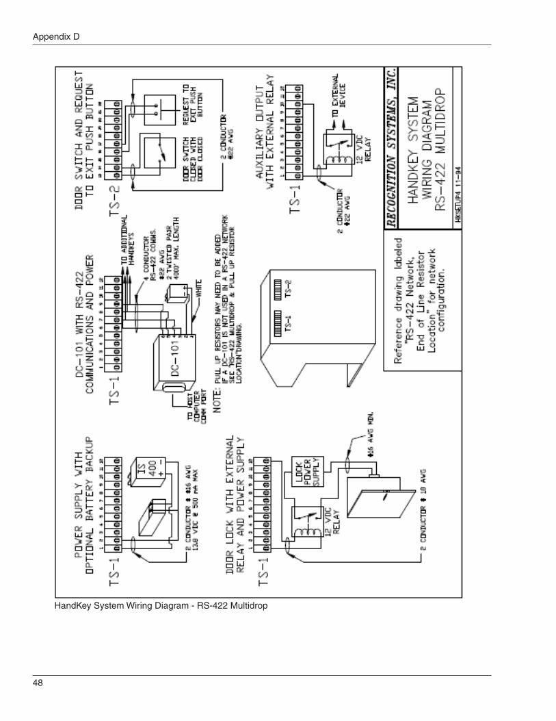
Appendix D
48
HandKey System Wiring Diagram - RS-422 Multidrop

ID3D-R Manual
49
RS-485 Network, End of Line Resistor Location

Appendix D
50
RS-422 Network, End of Line Resistor Location

ID3D-R Manual
51
Typical Wiring Diagram Stand-Alone

Appendix D
52
Typical Wiring Diagram Card System Interface

53
Index
A
Alarm duress ......................................................... 9Alarm monitoring ................................................... 3Authority Levels ................................................... 24Authorization levels .............................................. 23Automatically unlock ............................................ 28Auxiliary alarm ..................................................... 16
B
BackHand ............................................................ 32Battery backup ..................................................... 15Baud rate
SerialSetting ............................................................ 36
BeeperModes ............................................................... 36
BufferDatalog .................................................... 3, 10, 12Datalog(s) ......................................................... 34Transaction ........................................ 3, 10, 12, 34
C
Calibrate .............................................................. 37Camera ............................................................ 7, 37Capacity
Memory ......................................................... 3, 12Transaction .......................................................... 3User ................................................................ 3, 8
CardFormat(s) ............................................................ 1Reader ................................................................ 2
Interface ............................................................ 9Reader emulation ........................................ 17, 36Readers
Magnetic Stripe ................................................ 9Channel(s)
Communication ........................................... 12, 36One ................................................................... 12Zero ................................................................... 12
Circuit(s)Auxiliary input .................................................... 11
Cleaning .............................................................. 39Communication line shield ................................... 17Current draw .................................................... 2, 15
D
Data1 and Data0 ................................................. 17Datalog(s) .............................................................. 8
Buffer ........................................................... 10, 34Dimension .............................................................. 3Doors switch ........................................................ 37Door status ............................................................ 7Door switch ...................................................... 2, 11Duress code ................................................ 2, 9, 33
ModesSetting ............................................................ 34
E
Electrical hook-up ................................................ 14Enrollment ............................................................. 7
No hand ............................................................ 30Restoring data ................................................... 32User .............................................................. 9, 30
F
Finger position ..................................................... 21Format(s)
Card .................................................................... 1Input .................................................................... 9Output ............................................................. 3, 9Wiegand .............................................................. 3
FormatsInput .................................................................... 9Output ................................................................. 9
G
Ground ................................................................. 16
H
HandKeyMaster ................................................................. 8
Hand placement .................................................. 21Holiday ................................................................. 10Holiday table ........................................................ 27
Clearing ............................................................. 28Editing ............................................................... 28Printing .............................................................. 28
Host computer ....................................................... 8Host system interface .......................................... 11
I
IDLength ................................................................. 9Verification .......................................................... 7

Index
54
IdentityVerification
Procedures ..................................................... 20ID entry .................................................................. 2ID length .................................................. 2, 3, 9, 33Input
Auxiliary .............................................................. 2Formats ............................................................... 9Power .................................................................. 3Request to Exit .................................................... 3Voltage ................................................................ 2
Input(s)Auxiliary ...................................................... 16, 37Power ................................................................ 15Voltage .............................................................. 15Wiegand data .................................................... 17
Installation ........................................................... 13Electrical ........................................................... 14Table top ............................................................ 13Wall mount ........................................................ 14
J
Jewelry ................................................................ 21
K
Key ...................................................................... 5
L
Lock control relay ................................................. 16Lockout ................................................................ 22
M
Magnetic Stripe ................................................. 3, 9Memory
Battery replacement .......................................... 40Capacity .................................................... 2, 3, 12Reset ................................................................. 39Transaction ........................................................ 12User .............................................................. 8, 12
ModesAccess control ................................................... 21Beeper
Setting ............................................................ 36Command ......................................................... 23Duress code
Setting ............................................................ 34Output
Setting ............................................................ 35Reader ................................................................ 8
Setting ............................................................ 34Time and Attendance
Setting ............................................................ 33Mounting height ................................................... 13Mount(s)
Wall ..................................................................... 2
N
Network ..................................................... 1, 18, 32Receiving data from .......................................... 32Status ................................................................ 38
Notes of Concern ........ 5, 16, 17, 18, 29, 30, 34, 40
O
OperatingHumidity .............................................................. 4Temperature ........................................................ 3
Output Circuit Driver Replacement ...................... 40Output(s)
Auxiliary ............................................ 2, 10, 12, 16Setup .............................................................. 35
Auxiliary control ................................................... 2Current ................................................................ 2Formats ........................................................... 3, 9Lock ............................................................ 12, 16Lock Control ........................................................ 2Lock timer .......................................................... 35Setting modes ................................................... 35Voltage ................................................................ 2
P
Parts replacement ............................................... 39Password ....................................................... 23, 25
Default ............................................................... 25Setting ............................................................... 29
PortsCommunication ................................................... 3
PowerConnections ...................................................... 15Input .................................................................. 15
Power converter ................................................... 41Printer(s) ............................................................ 1, 8
Central .............................................................. 22Serial ................................................................... 8Setting options .................................................. 33
ProceduresIdentity
Verification ...................................................... 20PROM chip .......................................................... 41
R
ReaderCard .................................................................... 2Modes ................................................................. 8
Setting ............................................................ 34Ready display ...................................................... 35Reject override .................................................... 26Reject threshold ............................................... 4, 29Remote ................................................................ 27

ID3D-R Manual
55
ReplacementOutput circuit driver ........................................... 40Power converter ................................................ 41PROM chip ........................................................ 41Serial channel driver ......................................... 40
Request to Exit .................................... 3, 11, 16, 37Rings ................................................................... 21RS-232 ................................................................ 18RS-422 .......................................................... 17, 18RS-485 .......................................................... 17, 18
S
Score ....................................................................... 37
Service group commands .................................... 36Setup .......................................................................
39Shunt time ........................................................... 16Site code ................................................................ 9
Setting ............................................................... 18Site/facility code ............................................... 9, 36Specifications ........................................................ 2System status display .......................................... 37
T
Tamper alarm ...................................................... 11Template(s) ............................................................ 7
Hand ................................................................... 8Terminal connectors ............................................ 14Testing ................................................................. 18Throughput ............................................................ 4Time and Attendance ...................................... 2, 25
Setting mode ..................................................... 33Time and date
Setting ............................................................... 32Time intervals ...................................................... 10Time(s)
Start and stop ................................................... 10Time zone(s) .................................. 2, 10, 26, 27, 28
Auxiliary control outputs ...................................... 2Lock control Outputs ........................................... 2Table
Clearing .......................................................... 28Editing ............................................................. 27Printing ........................................................... 28
TransactionBuffer ..................................................... 10, 12, 34Capacity .............................................................. 3Memory ............................................................. 12
Try Again ............................................................. 22
U
UserAuthority level .................................................... 26Capacity .......................................................... 3, 8
Enrollment ..................................................... 9, 30Information
Printing ........................................................... 32Memory ......................................................... 8, 12Reject level ........................................................ 26Removing .......................................................... 31Time zone ......................................................... 27
V
Verification time ..................................................... 4Voltage
Input .............................................................. 2, 15Output ................................................................. 2
W
Wiegand ............................................................ 3, 9Data inputs ........................................................ 17
Wire gauge .................................................... 15, 16Wiring
Auxiliary alarm monitor ..................................... 16Door status switch ............................................. 16Request to Exit switch ....................................... 16RS-485/422 Network ......................................... 17

www.schlage.com
Ingersoll Rand’s Security Technologies Sector is a leading global provider of products and services that make environments safe, secure, and productive. The Sector’s market-leading products include electronic and biometric access control systems; time and attendance and personnel scheduling systems; mechanical locks and portable security, door closures and exit devices, steel doors and frames, architectural hardware and technologies and services for global security markets.
408.341.4110 www.ingersollrand.com
©2009 Ingersoll-Rand Company Limited P/N 70100-6008 Rev. 3.0 08/09
Schlage Biometric SolutionsIngersoll Rand Security Technologies1520 Dell AvenueCampbell, CA 95008Office: 866-861-2480/512-712-1413 (international)Fax: 866-303-1794/408-341-4111E-mail: [email protected]