DTIC · I ,.' L. . , .,,.. .... q,, , . .. .. . -, ...-. :...,...-.. :.--.L ..
I=D-RI2B SIB BRIDGE WOUND WEB NODULEMU EDO CORP SALT LAKE CITY UT 1/2FIBER SCIENCE DIV 1983
UNCLASSIFIED F/6 13/013
111f 10 L612 1250
mu 1.1 I~124
MICRCOP REOUIO ET HRNIONUE AUO TADRS-16-
j DOCUMENT NUNBER
SA 3032J0003
BRIDGE WOUND WE3 i40DULE
FINikL R. PORW.
APPROVED FOR PUBLIC RELEASE;
DISTRIBUTION UNILIMITED
OTTO"
MAY 12 1983
co, i..
L.L J (;OREflaIO
DISCLAIMER NOTICE
THIS DOCUMENT IS BEST QUALITYPRACTICABLE. THE COPY FURNISHEDTO DTIC COITAINED A SIGNIFICANTNUMBER OF PAGES WHICH DO NOTREPRODUCE LEGIBLY.
1
Ii
REVISIONS
IZONE LTR DESCRIPTION DATE APPD
DOCUMENT NUMBER
SA 3032J0003
BRIDGE WOUND WEB MODUJLE
FINAL REPORT
APPROVED FOR PUBLIC RELEASE S A 1i: ,DISTRIBUTION UNLIMITEDA
REV STATUS REV
OF SHEEfTS SHIEET~ *~ EEEEEEIDNA".___ FIBER
slums __ CORPON4RATIOP DIVSION* GUT____ TITLE
wDEN ENO
1M~tA 32500RE____________ I RELEASE DATE SCALE: UNTW lT O
r7
The views, opinions, and/or
findings contained in the report are
those of the authors and should not
be construed as an official Depart-
ment of the Army position, policy, or
a decision, unless so designated by
other communication.
:4
-2-
. . : i . . o . .: . . . . i - . . . . . ..
1.0 INTRODUCTION
This effort was undertaken in order that feasibility, design and
fabrication methods may be established for the manufacture of two wound web
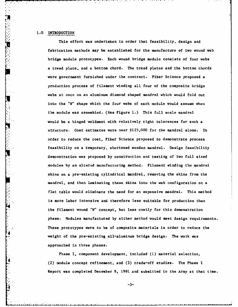
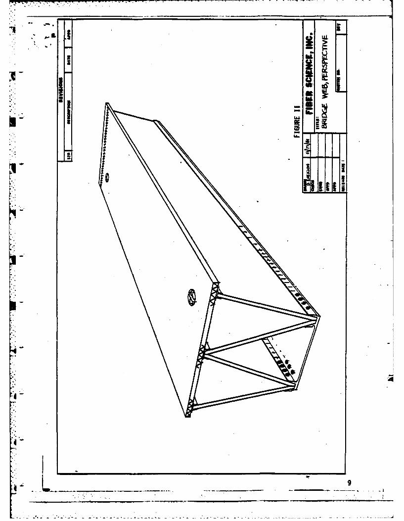
bridge module prototypes. Each wound bridge module consists of four webs
a tread plate, and a bottom chord. The tread plates and the bottom chords
were government furnished under the contract. Fiber Science proposed a
production process of filament winding all four of the composite bridge
webs at once on an aluminum diamond shaped mandrel which would fold out
into the "W" shape which the four webs of each module would assume when
the module was assembled. (See Figure 1.) This full scale mandrel
would be a hinged weldment with relatively tight tolerances for such a
structure. Cost estimates were near $125,000 for the mandrel alone. In
order to reduce the cost, Fiber Science proposed to demonstrate process
feasibility on a temporary, shortened wooden mandrel. Design feasibility
demonstration was proposed by construction and testing of two full sized
modules by an altered manufacturing method. Filament winding the mandrel
skins on a pre-existing cylindrical mandrel, removing the skins from the
mandrel, and then laminating these skins into the web configuration on a
flat table would eliminate the need for an expensive mandrel. This method
is more labor intensive and therefore less suitable for production than
the filament wound "W" concept, but less costly for this demonstration
phase. Modules manufactured by either method would meet design requirements.
These prototypes were to be of composite materials in order to reduce the
weight of the pre-existing all-aluminum bridge design. The work was
approached in three phases.
Phase I, component development, included (1) material selection,
(2) module concept refinement, and (3) trade-off studies. The Phase I
Report was completed December 8, 1981 and submitted to the Army at that time.
V-3-
z>
mj
II
434
Phase II, engineering design and documentation, included the creation
of engineering drawings, manufacturing procedures, and test samples which
were representative of the bridge module design. The samples were tested
to failure to provide confidence in the wound web design. Design drawings,
manufacturing procedures, and tests were completed and submitted with the
Phase II Report on 13 August 1982.
Phase III of the effort consists of fabrication of eight wound bridge
webs in full scale and the assembly of the webs with hardware for one
complete interior bridge bay. The fabrication details for the wound
bridge webs and associated hardware are included in this report.
II. RESULTS AND CONCLUSIONS
"--4-,-2The filament wound process for the manufacture of a bridge web was
demonstrated to be both feasible and practical. This program identified
some process modifications that are required for low cost production.
(Se -Ft 3) The modified process will retain the attractive features
of the "wound W" process (sae-Figures 4 and 5), but will greatly reduce
tooling costs and improve producibility resulting in lower labor
costs.
2. The winding angle may be modified from 45' to 50* to improve the
winding pattern without impacting the structural integrity, but
should be left at 45 for maximum strength at minimum thickness. (See
Addendum IV.)
'3. The design requirements for edge filler are met by the syntactic foam
which Fiber Science used. This foam reduced the weight by an average
of eight pounds per web over the weight of solid epoxy resin edge
*Q filler. Tests of the syntactic foam compressive strength, although
high enough to meet design requirements, were not as high as anticipated.-
6 -5-
- -- - PV.C FOAM II~
- - - 14M)( NOM0,) w.c
F-, 7 7 R 5052 ALUM W.C
-t I URETHANE FOAM COfRE
ACG 4.,05 ALUM WC
1400E GLASS F4CI
S2 GLASS FACES
C EL.I o K 6000 F'AC.F
4
IL)
T T-I
WEE PAS W IP ITOT E- I I L . 5
FIGUR 2.19I P ,A ,S
*ENGR. T7-LjTNELL. 7jj/ REVISED DATE REPORT'DU FIBERCHECK EDSCIENCE PAGE
CURPORA TWA DIVISION
4 -6-
The compressive test result was 3900 psi avg. 3M Company "Scotchply"
XP-241 syntactic foam conforming to MIL-S-24154A Type I with a foam
density of 38 pounds per cubic foot is reported* to have a yield strength
of 5000 psi. Foam conforming to the same Mil spec in a 44 pound per
"c cubic foot density is reported* to have a compressive yield strength
of 10,000 psi. Unfilled epoxy resin has a density of 72.63 pounds per
cubic foot. The foam used by Fiber Science was 39 pounds per cubic
foot. It is recommended that the density of the foam be increased to
44 pounds per cubic foot in order to obtain higher compressive strength.
4. Results and conclusions from Phases I and II may be found in Addenda
I, II and III.
III. PERFORMANCE
Fiber Science Division has complied with the requirements of
Section C of the contract. The work required by Contract Section
C.2.a, Concept Development, was performed and reported as Phase I of
the effort. The Army response to the Phase I Report with its attendant
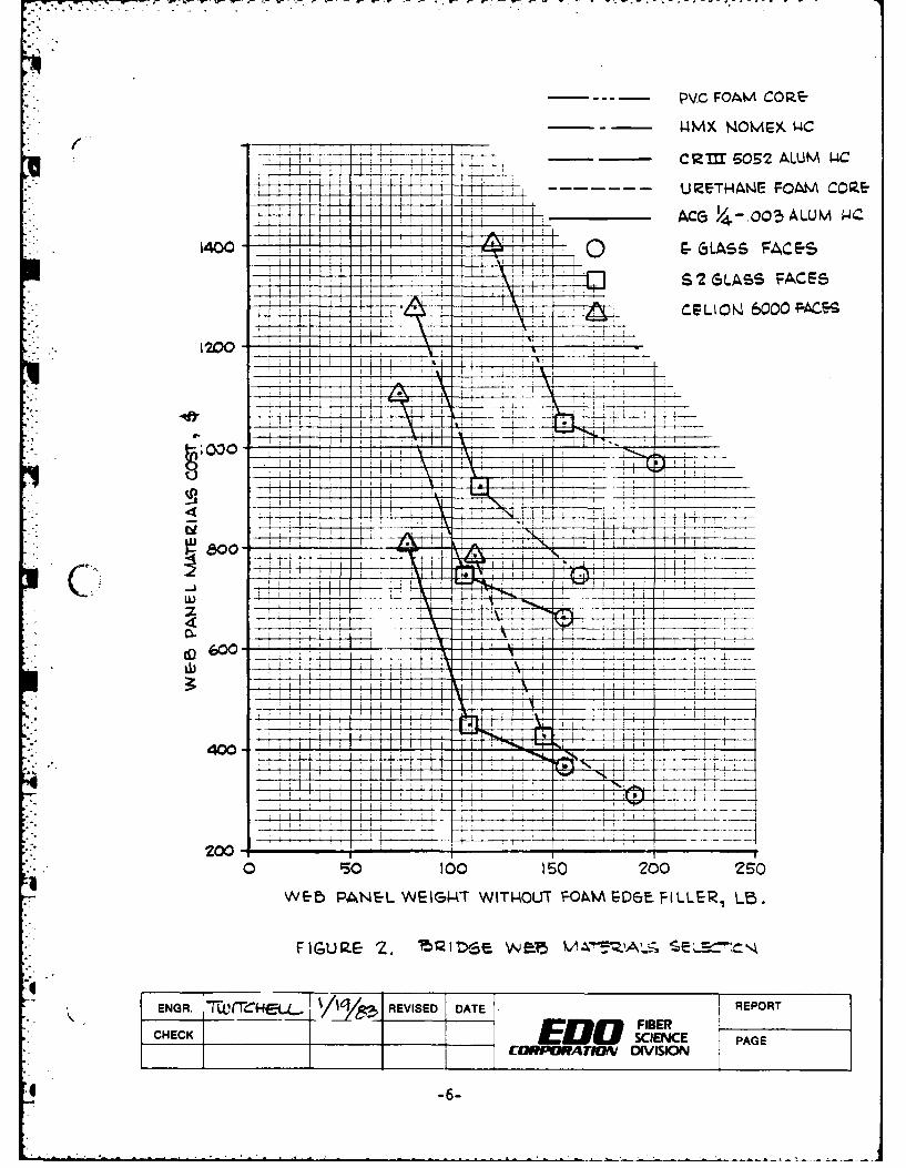
instructions may be found in Addendum II of this report. Figure 1, of
the Phase I Report, has been modified at Army request to show web
panel cost and weight, with costs for graphite-epoxy representative
of the materials used in Phase III. The revised Figure 1 is included
as Figure 2 in this report. The Phase II effort as required by Contract
Section C.2.b, Engineering Design and Documentation, may be found in
Addendum III of this report. The Phase III effort as required by
Contract Section C.2.c, Hardware Fabrication, is reported in this
section.
*Testing reported in "Scotchply" KP-241 Syntactic Foam Technical Data
Sheet #11, dated January 1969.
-7-
IV. PHASE III REPORT, HARDWARE FABRICATION
This phase of the contracted effort was defined as the manufacture
of the bridge module in full scale as defined by the design resultiL,;
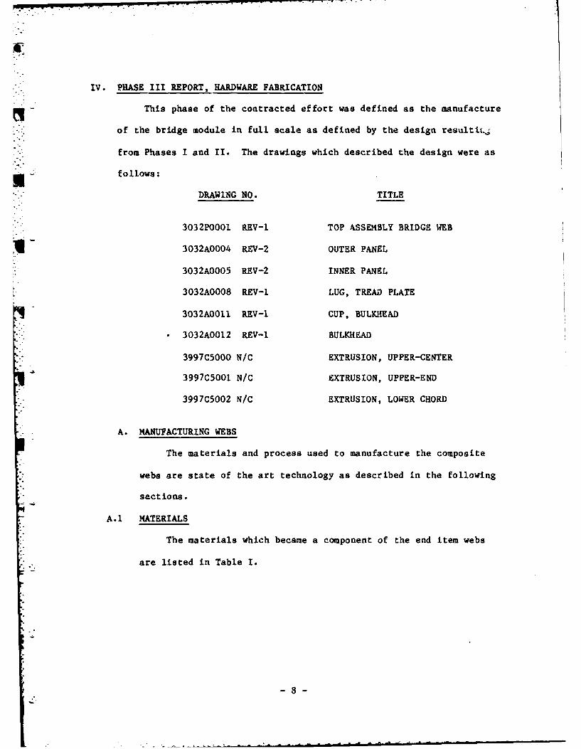
from Phases I and II. The drawings which described the design were as
fofllows:
DRAWING NO. TITLE
3032P0001 REV-I TOP ASSEMBLY BRIDGE WEB
3032A0004 REV-2 OUTER PANEL
3032A0005 REV-2 INNER PANEL
3032AG008 REV-I LUG, TREAD PLATE
3032A0011 REV-i CUP, BULKHEAD
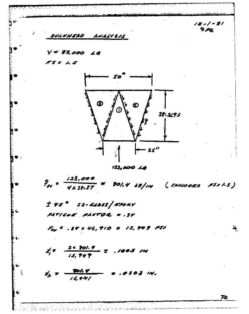
3032A0012 REV-1 BULKHEAD
3997C5000 N/C EXTRUSION, UPPER-CENTER
3997C5001 N/C EXTRUSION, UPPER-END
3997C5002 N/C EXTRUSION, LOWER CHORD
A. MANUFACTURING WEBS
The materials and process used to manufacture the composite
webs are state of the art technology as described in the following
sections.
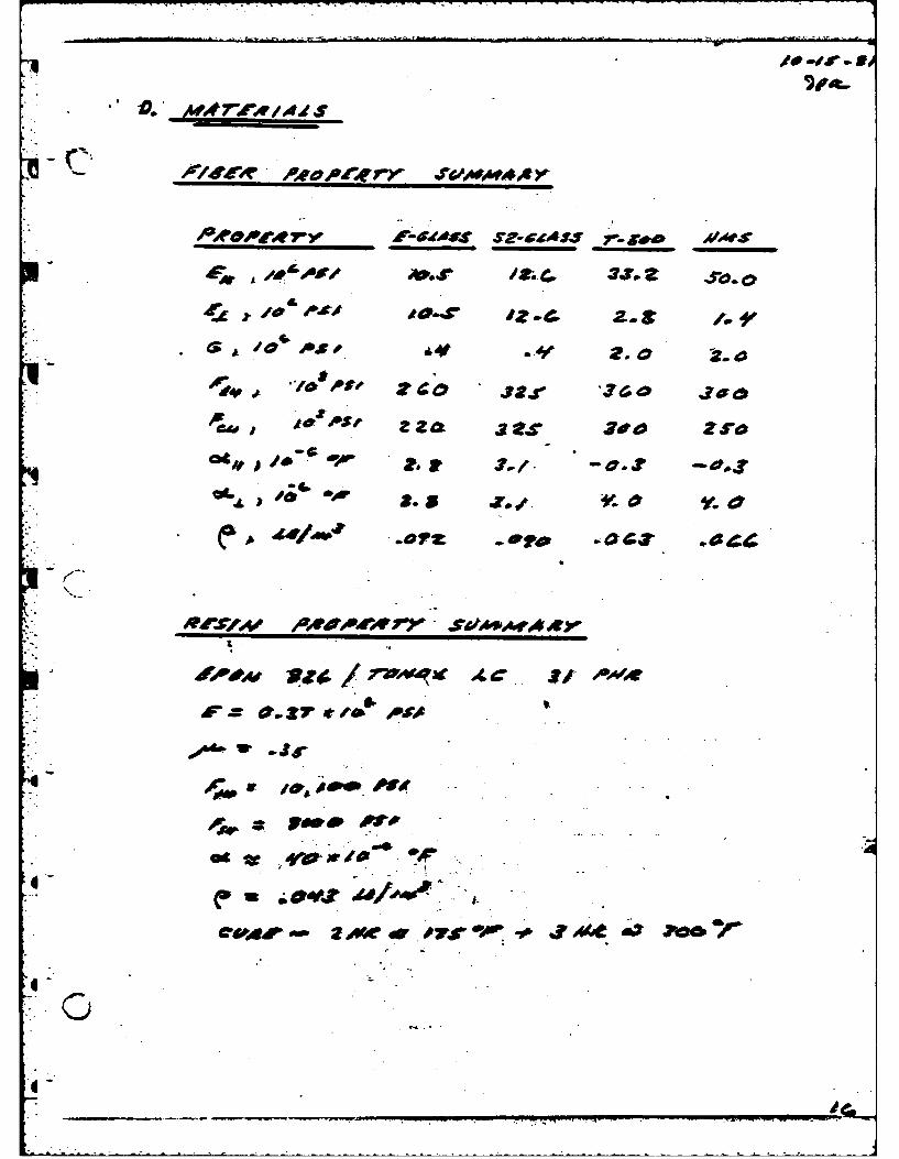
A.i MATERIALS
The materials which became a component of the end item webs
are listed in Table I.
-8-
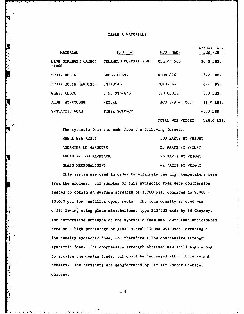
TABLE I MATERIALS
APPROX WT.
MATERIAL MFG. BY MFG. NAME PER WEB
HIGH STRENGTH CARBON CELANESE CORPORATION CELION 600 30.8 LBS.FIBER
EPOXY RESIN SHELL CHEM. EPON 826 15.2 LBS.
EPOXY RESIN HARDENER UNIROYAL TONOX LC 6.7 LBS.
GLASS CLOTH J.P. STEVENS 120 CLOTH 3.0 LBS.
ALUM. HONEYCOMB HEXCEL ACG 3/8 - .003 31.0 LBS.
SYNTACTIC FOAM FIBER SCIENCE 41.3 LBS.
TOTAL WEB WEIGHT 128.0 LBS.
The sytactic foam was made from the following formula:
SHELL 826 RESIN 100 PARTS BY WEIGHT
ANCAMINE LO HARDENER 25 PARTS BY WEIGHT
ANCAMINE LOS HARDENEK 25 PARTS BY WEIGHT
GLASS MICROBALLOONS 42 PARTS BY WEIGHT
This system was used in order to eliminate one high temperature cure
from the process. Six samples of this syntactic foam were compression
tested to obtain an average strength of 3,900 psi, compared to 9,000 -
10,000 psi for unfilled epoxy resin. The foam density as used was
0.023 lb/in, using glass microballoons type B23/500 made by 3M Company.
The compressive strength of the syntactic foam was lower than anticipated
because a high percentage of glass microballoons was used, creating a
low density syntactic foam, and therefore a low compressive strength
syntactic foam. The compressive strength obtained was still high enough
to survive the design loads, but could be increased with little weight
€" penalty. The hardeners are manufactured by Pacific Anchor Chemical
Company.
j - 9 -
The aluminum extrusions used to attach the webs to the tread plate
and to the bottom chord were extruded by Kaiser Aluminum from 6061
aluminum stock in the "0" condition and subsequently heat treated to the
T-6 condition.
Bulkheads were manufactured from the same resins as the web, but
the reinforcement was high strength carbon woven fabric Style W-133,
made by Fiberita Corporation. The honeycomb used in the bulkhead was
ALH-CG/3003 commercial grade honeycomb by Unicel Corporation, witb a
thickness of 0.50 inches.
Glass cloth insulation was bonded to the composite faces where
intimate contact was expected between aluminum and carbon. The intent
of this design feature is to break up any galvanic cell which might
corrode the aluminum in contact with carbon. Further corrosion prevention
was provided by installing stainless steel fasteners wet with a strontium
chromate primer coating. The sacrificial primer was purchased to military
specifications MIL-P-23377 Type I.
A.2. WEB MANUFACTURING PROCESS
The bridge web manufacturing process was studied in Phase I of this
project. The recommendation made on page 7 of Phase I Report was to hand
layup the entire web from "Knytex" a brand name of commercially preplied
broadgoods. The government position taken in response to the Phase I
Report requeseted determination of the actual cost of the "Knytex" fabric
made with low cost graphite fiber. Careful comparison of graphite "Kyntex"
was made with the filament wound "W" process to determine which is less
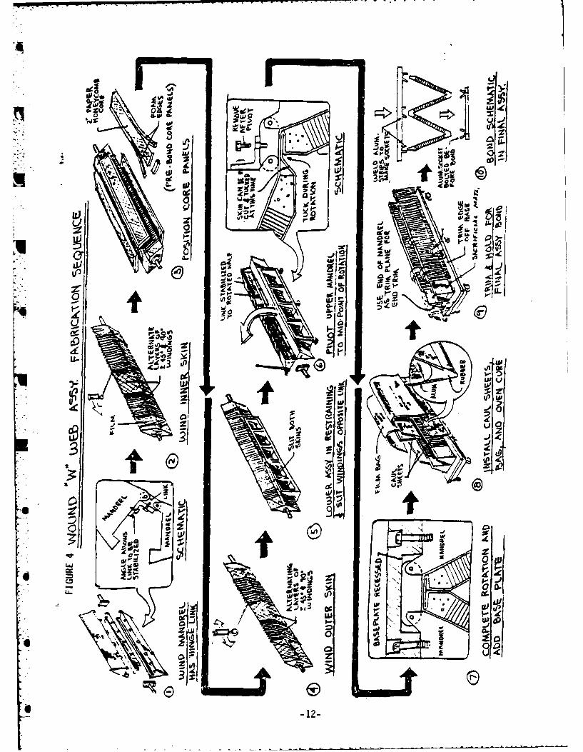
costly. The "W" process (see Figure 4 and 5) which was first presented
in the Fiber Science proposal for this work, is direct filament winding
-- - - -
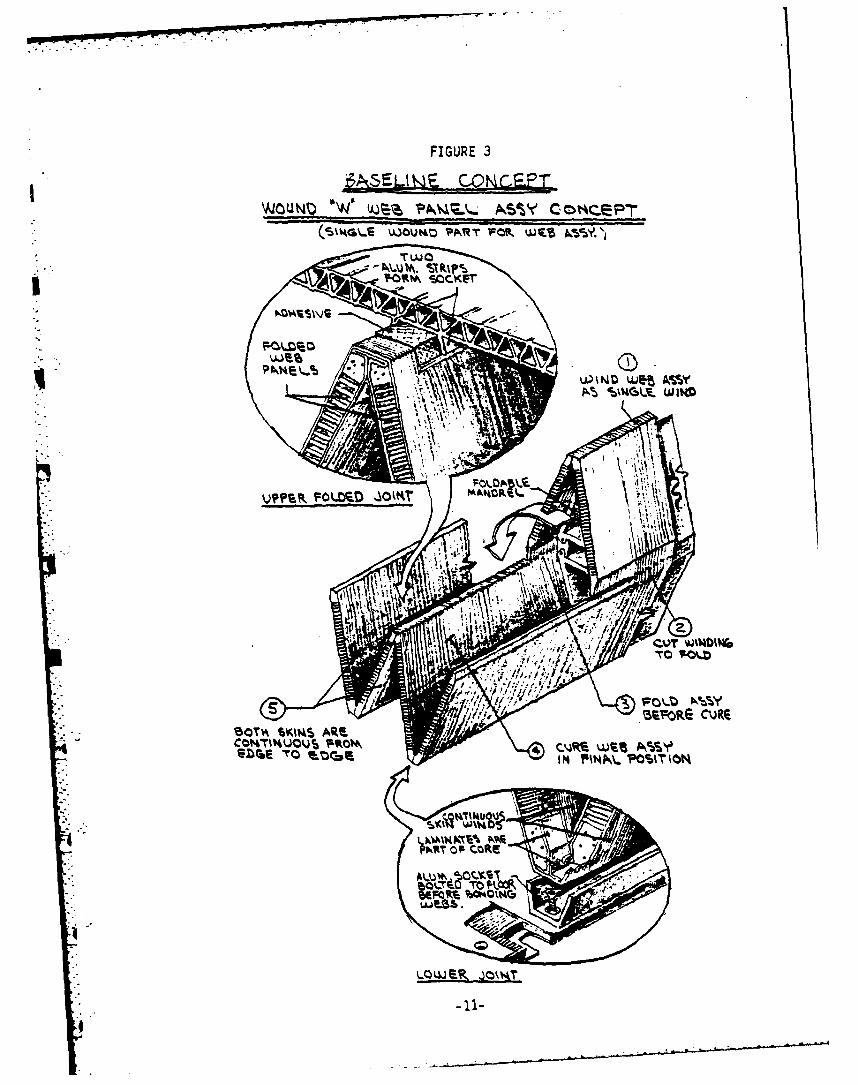
FIGURE 3
WOUNM) 'W"~ 4 cotQcep-r
(7v=S UMG WART FMR WE'S A4Csy.
Tw
/AW SIMPST~Ub&(
T*010A SOCKET ~
C4~JO~~ F\is
~WN AR!. ASSY u~
r0W6.R .k4T
- 1itI I
01
OCIO
01
e 30
0. -ud§ e
1 (9
E~Lo
6 6j
X L4
upon a diamond shaped mandrel. In that process the windings were slit
along one side and folded out into a "W" after the windings were "B"
staged.
During the Phase II work, more detailed cost estimates revealed that
knitting machine setup and material waste charges would indeed make the
"Knytex" process more expensive that the "W" process The latter process
was, therefore, selected for the production process. Cost estimates for
a full scale mandrel to be used for fabrication of the eight webs funded
on the contract ranged near $125,000. This cost was not included in the
Fiber Science proposal, which only contained $6,808 for tool materials
and construction labor. The mandrel proposed was a shortened wooden
mandrel as discussed in the introduction. To make a full size mandrel
twenty-three feet long which does not sag in the middle requires stiffer,
less dense materials than wood and results in the high price. The demon-
stration winding manufacturing process used to evaluate the two approaches
was as follows;
1. Phase III web skins were filament wound on a large
existing cylindrical mandrel, cut and laminated into the
web configuration complete with honeycomb core.
2. A scaled down wooden mandrel was fabricated to demonstrate
both winding techniques for the diamond shaped mandrel and
the slitting and folding operation. The demonstration mandrel
* was full sized in cross section but the length was reduced to
six feet from the twenty-three feet required for a full scale
web.
-13-
.. . . . . . .
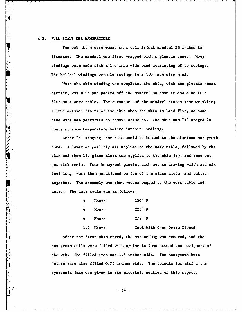
A.3. FULL SCALE WEB MANUFACTURE
The web skins were wound on a cylindrical mandrel 38 inches in
diameter. The mandrel was first wrapped with a plastic sheet. Hoop
windings were made with a 1.0 inch wide band consisting of 13 rovings.
The helical windings were 16 rovings in a 1.0 inch wide band.
When the skin winding was complete, the skin, with the plastic sheet
carrier, was slit and peeled off the mandrel so that it could be laid
flat on a work table. The curvature of the mandrel causes some wrinkling
- in the outside fibers of the skin when the skin is laid flat, so some
hand work was performed to remove wrinkles. The skin was "B" staged 24
hours at room temperature before further handling.
After "B" staging, the skin could be bonded to the aluminum honeycomb.
core. A layer of peel ply was applied to the work table, followed by the
skin and then 120 glass cloth was applied to the skin dry, and then wet
out with resin. Four honeycomb panels, each cut to drawing width and six
feet long, were then positioned on top of the glass cloth, and butted
together. The assembly was then vacuum bagged to the work table and
cured. The cure cycle was as follows:
4 Hours 1500 F
4 Hours 2250 F
4 Hours 2750 F
1.5 Hours Cool With Oven Doors Closed
After the first skin cured, the vacuum bag was removed, and the
honeycomb cells were filled with syntactic foam around the periphery of
the web. The filled area was 1.5 inches wide. The honeycomb butt
*4 joints were also filled 0.75 inches wide. The formula for mixing the
syntactic foam was given in the materials section of this report.
-14-
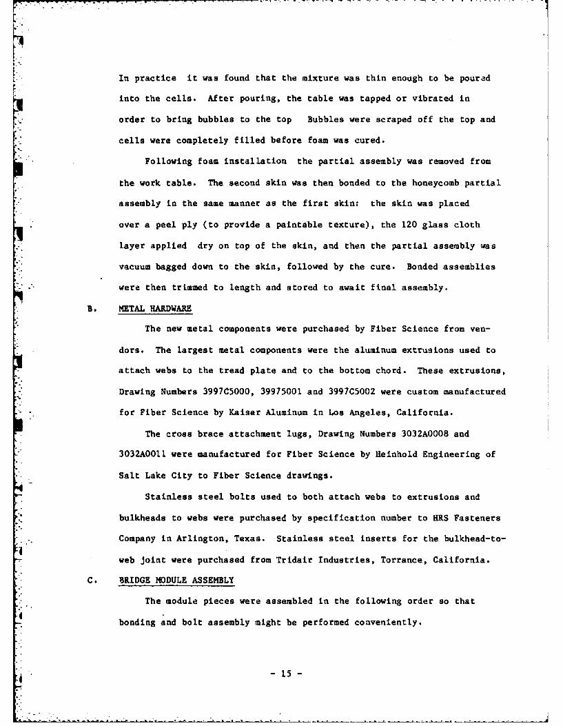
In practice it was found that the mixture was thin enough to be poured
into the cells. After pouring, the table was tapped or vibrated in
order to bring bubbles to the top Bubbles were scraped off the top and
cells were completely filled before foam was cured.
Following foam installation the partial assembly was removed from
the work table. The second skin was then bonded to the honeycomb partial
assembly in the same manner as the first skin: the skin was placed
over a peel ply (to provide a paintable texture), the 120 glass cloth
layer applied dry on top of the skin, and then the partial assembly was
vacuum bagged down to the skin, followed by the cure. Bonded assemblies
were then trimmed to length and stored to await final assembly.
B. METAL HARDWARE
The new metal components were purchased by Fiber Science from ven-
dors. The largest metal components were the aluminum extrusions used to
attach webs to the tread plate and to the bottom chord. These extrusions,
Drawing Numbers 3997C5000, 39975001 and 3997C5002 were custom manufactured
for Fiber Science by Kaiser Aluminum in Los Angeles, California.
The cross brace attachment lugs, Drawing Numbers 3032A0008 and
3032A0011 were manufactured for Fiber Science by Heinhold Engineering of
Salt Lake City to Fiber Science drawings.
Stainless steel bolts used to both attach webs to extrusions and
bulkheads to webs were purchased by specification number to HRS Fasteners
*Company in Arlington, Texas. Stainless steel inserts for the bulkhead-to-
web joint were purchased from Tridair Industries, Torrance, California.
C. BRIDGE MODULE ASSEMBLY
The module pieces were assembled in the following order so that
bonding and bolt assembly might be performed conveniently.
d -'51-
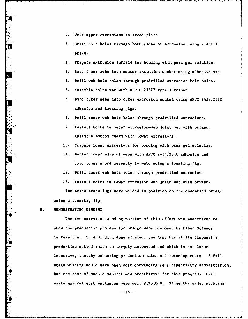
1. Weld upper extrusions to tread plate
2. Drill bolt holes through both sides of extrusion using a drill
press.
3. Prepare extrusion surface for bonding with pasa gel solution.
4. Bond inner webs into center extrusion socket using adhesive and
5. Drill web bolt holes through predrilled extrusion bolt holes.
6. Assemble bolts wet with MLP-P-23377 Type J Primer.
7. Bond outer webs into outer extrusion socket using APCO 2434/2310
adhesive and locating jigs.
8. Drill outer web bolt holes through predrilled extrusions.
9. Install bolts in outer extrusion-web joint wet with primer.
Assemble bottom chord with lower extrusions.
10. Prepare lower extrusions for bonding with pasa gel solution.
11. Butter lower edge of webs with APCO 2434/2310 adhesive and
bond lower chord assembly to webs using a locating jig.
12. Drill lower web bolt holes through predrilled extrusions
13. Install bolts in lower extrusion-web joint wet with primer.
The cross brace lugs were welded in position on the assembled bridge
using a locating jig.
D. DEMONSTRATING WINDING
The demonstration winding portion of this effort was undertaken to
show the production process for bridge webs proposed by Fiber Science
is feasible. This winding demonstrated, the Army has at its disposal a
production method which is largely automated and which is not labor
intensive, thereby enhancing production rates and reducing costs A full
scale winding would have been most convincing as a feasibility demonstration,
but the cost of such a mandrel was prohibitive for this program. Full
scale mandrel cost estimates were near $125,000. Since the major problems
- 16 -
°.
were expected in turnaround (a form attached to the ends of filament
winding mandrels to facilitate fiber direction reversal) design and
mandrel folding, a shorter mandrel was considered to be a reasonable
compromise. The turnaround problem would not be diminished by a short
mandrel of full sized cross section but folding a short nandrel would be
easier. As the demonstration winding progressed, the anticipated problems
were found to be real but solvable. A discussion of the problems and
problem solutions follow.
D.1 TURNAROUNDS
Several turnaround designs were tried before one was found which
brought reasonable results. This turnaround design was obtained by
calculating the perimeter length of the diamond portion of the mandrel and
then determining the diameter of a circle which has the same circumference
as the mandrel perimeter. The circle was cut from plywood and used as
the end piece of the turnaround. The remainder of the turnaround contour
was calculated. An existing mandrel stand was used which offered 28 inches
on each end for turnaround. More distance, approximately 36 inches,
would be required to provide a uniform winding pattern to the end of the
mandrel at the ±450 winding angle designed in the web skin laminate.
As a result, the ±450 winding in the inside skin of the demo piece
were poorly distributed due to bridging and slipping of fibers during
winding. A satisfactory winding pattern was obtained on the outer skin
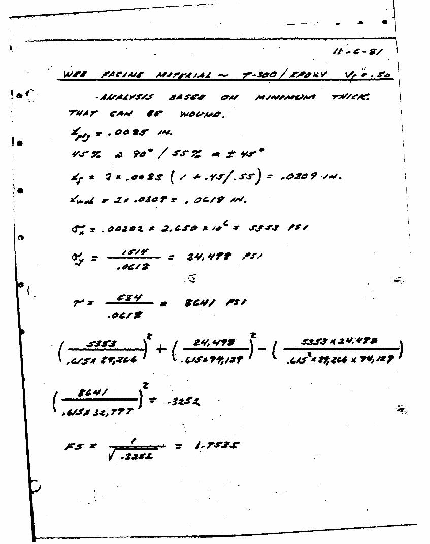
by changing the helical winding angle to 550. Analysis reveals, however,
that the winding angle should not be increased beyond 500 because of
decreasing composite shear strength (see Addendum 1). A completely
satisfactory turnaround would be achieved with proper tooling
- 17 -
D.2. MANDREL FOLDING
The difficulties with the folding operation began as soon as the
slit was made (Figure 4). The skins and the honeycomb tended to fall
away from the mandrel. Elastic cords were fastened around the mandrel
halves to secure the webs to the mandrel, and still the webs sagged away
from the mandrel between cords stretching the skins and causing
wrinkles. As a result, it was decided that the cut shown in the Figure 2,
Step 6 schematic would be deleted. The weight of the six foot long
wooden mandrel made the tuck operation so awkward that it was poorly
done and became a lump which crushed the honeycomb. The honeycomb has
not been dimensionally stabilized and stretched during handling and
folding so that it was caught and crushed as the fold was made. None of
these problems was so serious that it could not be overcome with proper
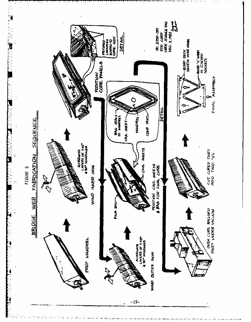
tooling and procedure After considering this process, Fiber Science
has concluded that a variation of the wound "W" concept would require
much less tooling and probably fewer manhours (see Figure 5), while
+* retaining the most desirable features of the previous version, namely,
low labor intensity and producibility.
- 18 -
-2 0
IL
4C
* IlI
Idp
V!A10LC<
T MLL.-
4L c3
4 w
iiL
4 - -19
.2 . -- -. - - ~ ....... ~ -....-..- A......... ..Z..: - ..
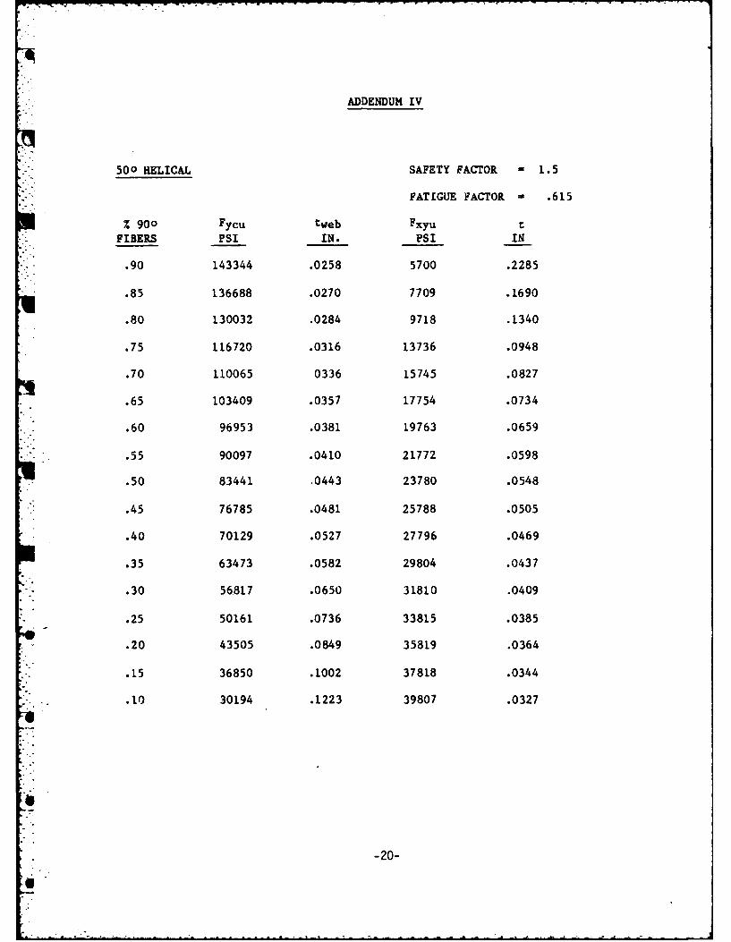
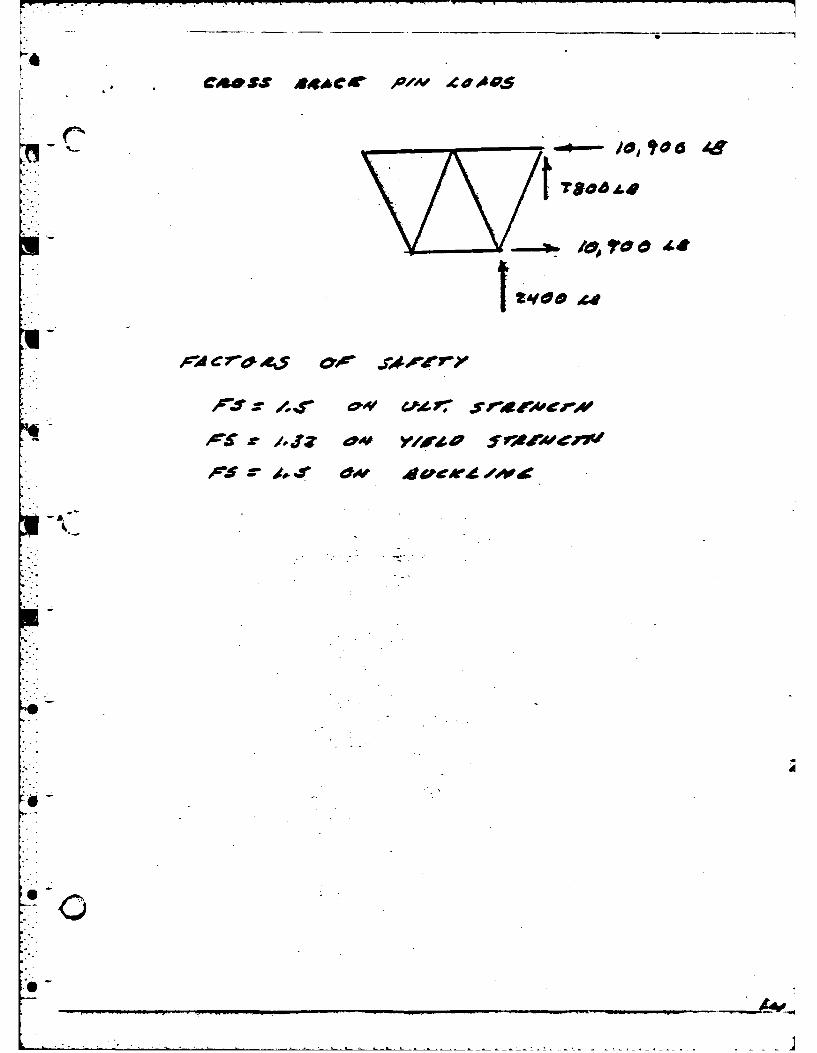
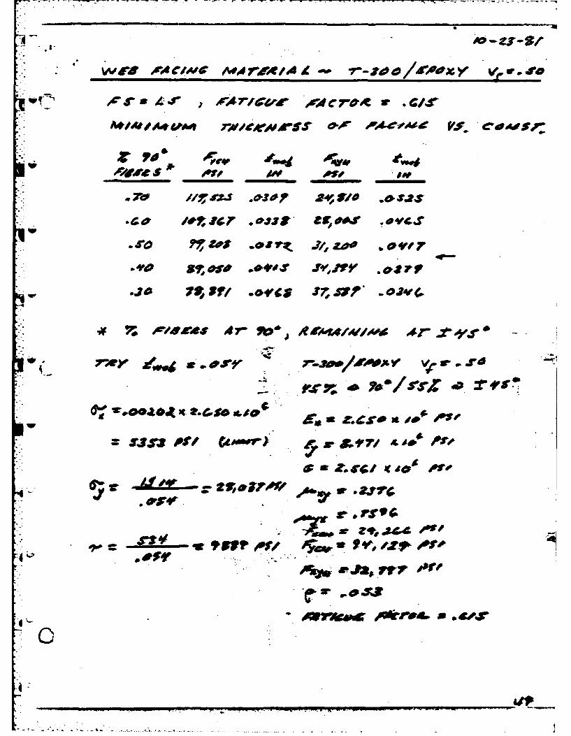
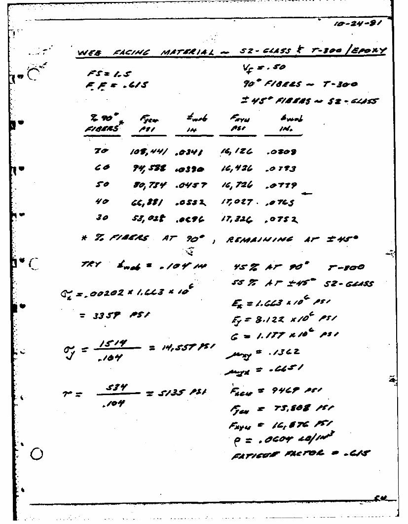
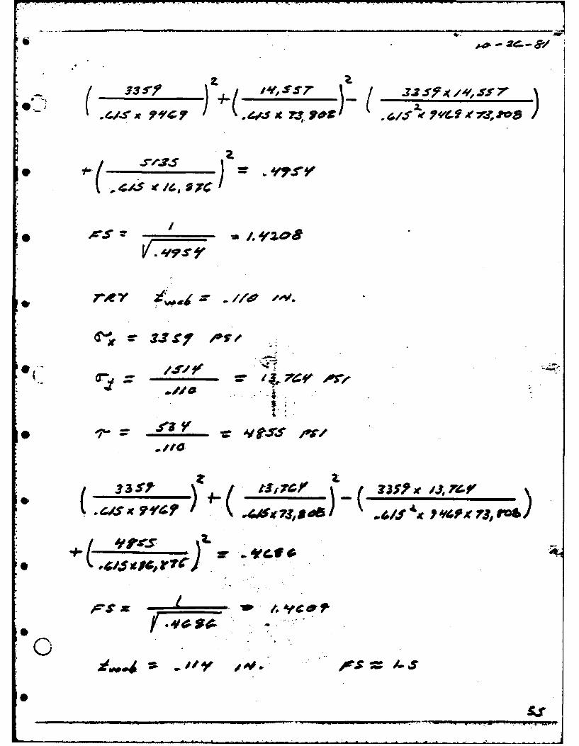
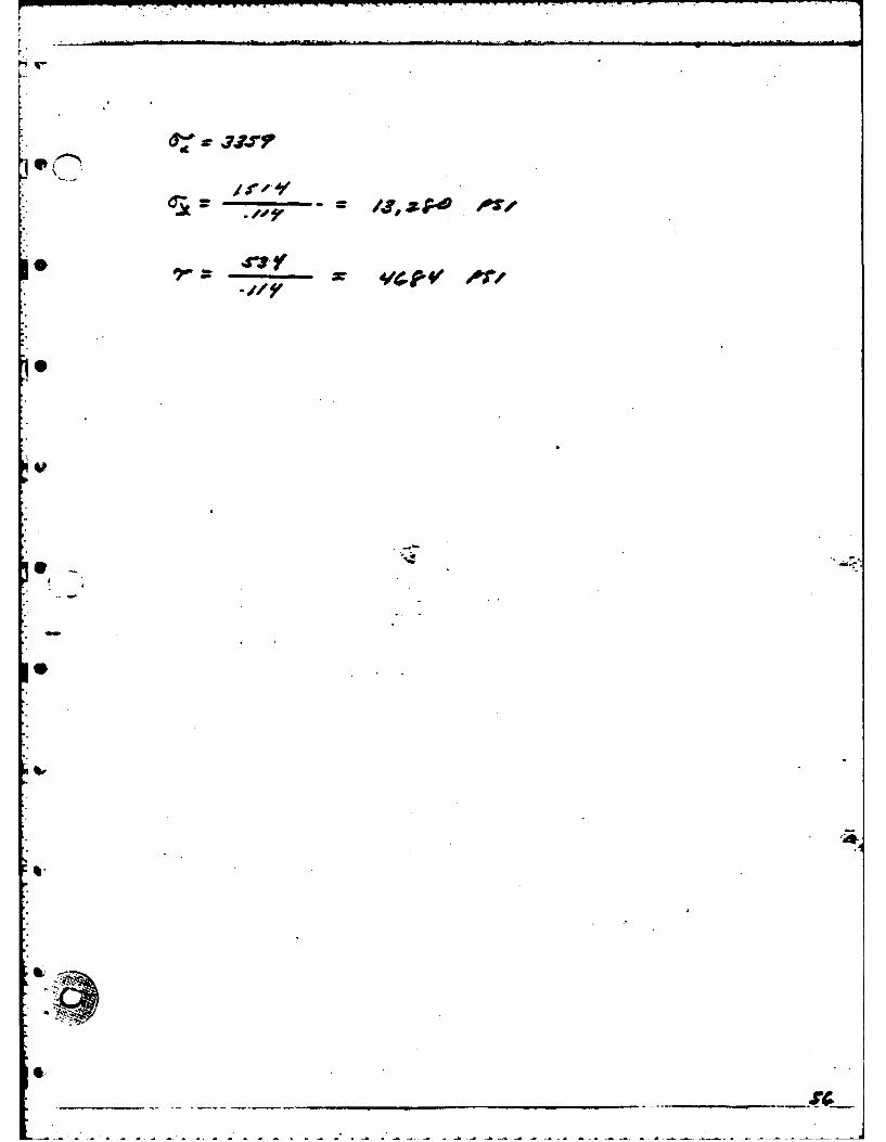
ADDENDUM IV
500 HELICAL SAFETY FACTOR - 1.5
FATIGUE FACTOR - .615
% 900 Fycu tweb Fxyu tFIBERS PSI IN. PSI IN
- .90 143344 .0258 5700 .2285
.85 136688 .0270 7709 .1690
.80 130032 .0284 9718 .1340
.75 116720 .0316 13736 .0948
.70 110065 0336 15745 .0827
.65 103409 .0357 17754 .0734
.60 96953 .0381 19763 .0659
.55 90097 .0410 21772 .0598
.50 83441 .0443 23780 .0548
.45 76785 .0481 25788 .0505
.40 70129 .0527 27796 .0469
.35 63473 .0582 29804 .0437
.30 56.817 .0650 31810 .0409
.25 50161 .0736 33815 .0385
.20 43505 .0849 35819 .0364
.15 36850 .1002 37818 .0344
.10 30194 .1223 39807 .0327
-20-
-
E7
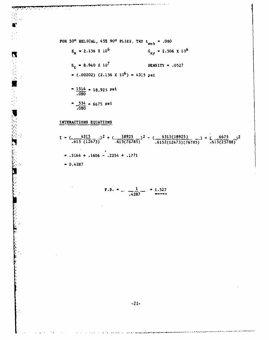
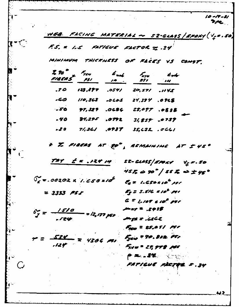
FOR 500 HELICAL, 45% 900 PLIKS, TRY tweb "- .080
Ex = 2.136 X 10⁶ Giy W 2.506 X 10⁶
Et - 8.940 X 10⁷ DENSITI - .0527
" , (.00202) (2.136 X 10⁶) , 4315 psi
-1514 18,925 psi.080
S34 6675 psi1• .080
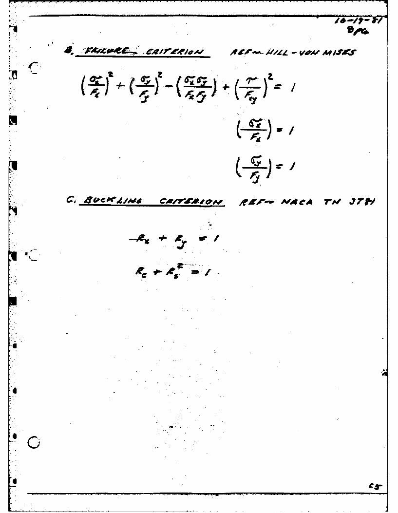
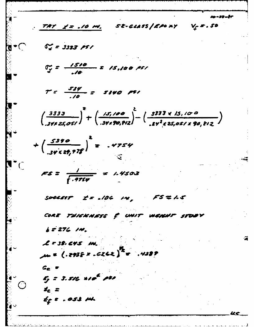
INTERACTIONS EQUATIONS
L. 4315 _)2 + ( 18925 _)2 - ( 4315(18925) __) + L 6675 _)2.615 (12473) .615(76785) .6152(12473)(76785) .615(25788)
, .3164 + .1606 - .2254 + .1771
S-" " = 0.4287
F.S.- 1 - 1.527
.45
-21-
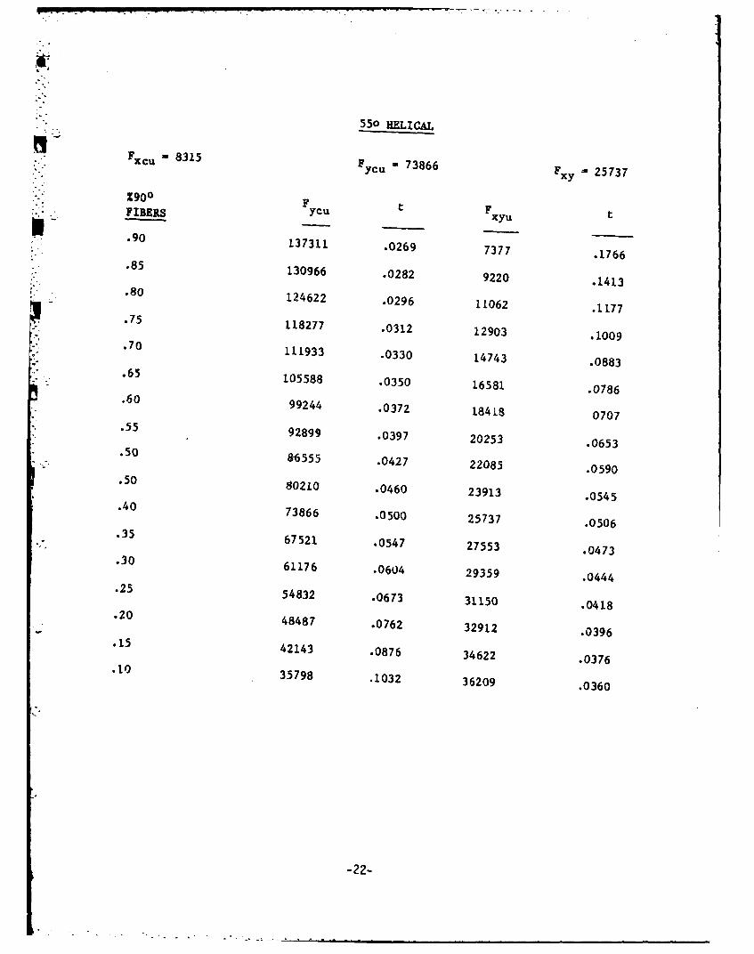
550 HELICAL,_Fxc u -8315F
736,.-.5-ycu
73866 Fxy = 25737
%900 F tFFIBERS ycu xyu
.90 137311 .0269 7377 .1766.85 130966 .0282 9220 .1413.80 124622 .0296 11062 .1177.75 118277 .0312 12903 .1009.70 111933 .0330 14743 .0883.65 105588 .0350 16581 .0786.60 99244 .0372 18418 0707.55 92899 .0397 20253 .0653.50 86555 .0427 22085 .0590.50 80210 .0460 23913 .0545.40 73866 .0500 25737 .0506.35 67521 .0547 27553 .0473.30 61176 .0604 29359 .0444.25 54832 .0673 31150 .0418.20 48487 .0762 32912 .0396.15 42143 .0876 34622 .0376.10 35798 .1032 36209 .0360
-22-
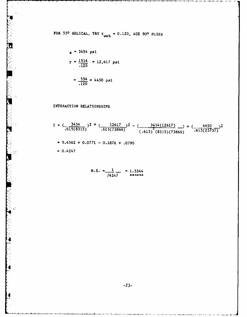
FOR 550 HELICAL, TRY tweb 0.120, 40% 900 PLIES
x 3454 psi
y 1 5 14 12,617 psi.120
534 =4450 psi.120
INTERACTION RELATIONSHIPS
(_ 3454 )2 + ( 12617 )2 _ 3454(12617) ) + ( 4450
.615(8315) .615(73866) (.615) (8315)(73866) .615(25737)
- 0.4562 + 0.0771 - 0.1876 + .0790
=0.4247
M.S. -- 1 1.5344/4247
-23-
4 .
ADDENDUM I
REVISIONSKIZONE LTR jDescitirrON IDATE IAPPO
DOCUMENT NUMBER
SA 3032-J-0001
TITLE
BRIDGE WOUND WEB MODULEPHASE I REPORT
____ _ -FIBER SCIENCE, INC._________SALT LAKE CITY, UTAH 64116
TITLEIT -MM( '!mcz : t* M -!.IEm ij IC iP~sm I amc
______ COD IDE z rSZ 0NT a-NO Rev
________ uuium /:-9 5,/ as: UNWWTr hulSNT I OF 78
"The views, opinions, and/or findings contained inthe report are those of the author(s) and shouldnot be construed as an official Department of theAmy position, policy, or decision, unless so des-ignated by other documentation."
I
2-2
I-,
1. INTRODUCTION
The Wound Bridge Web contract is an effort tO reduce the weightof the existing bridge. The wound bridge web contract, which providesfor the determination of contract feasibility, design, fabrication,test and assembly of two bridge web modules, was received at FiberScience on September 28, 1981.
Phase I of the contract, Component Development, includes(1) material selection, (2) module concept refinement, and (3)trade off studies. Phase II of the contract will consist ofengineering design and documentation. Phase III will be fabricationof hardware for one complete interior bridge bay and assembly ofparts.
,. This is the final report under Phase I of the contract.
3
~3Il
. t .
6
MI- AIMS AND OBJECTIVES OF PHASE I
, 1. Determine weight versus cost for various material combinationsand physical configurations which meet the requirements ofAttachment I to the Statement of Work.
2. Determine cost of labor and materials for each of the candidatemanufacturing methods proposed for large scale manufacture ofthe bridge webs.
3. Prepare recommendations based on cost, weight, fatigue strength,ease of manufacture and efficient material usage.
4. Prepare preliminary designs for bridge web, web attachments,bulkheads, and redesign cross braces if necessary.
* 5. Determine weight and cost of the recommended preliminarydesign in large scale production.
II.
0.
0"!
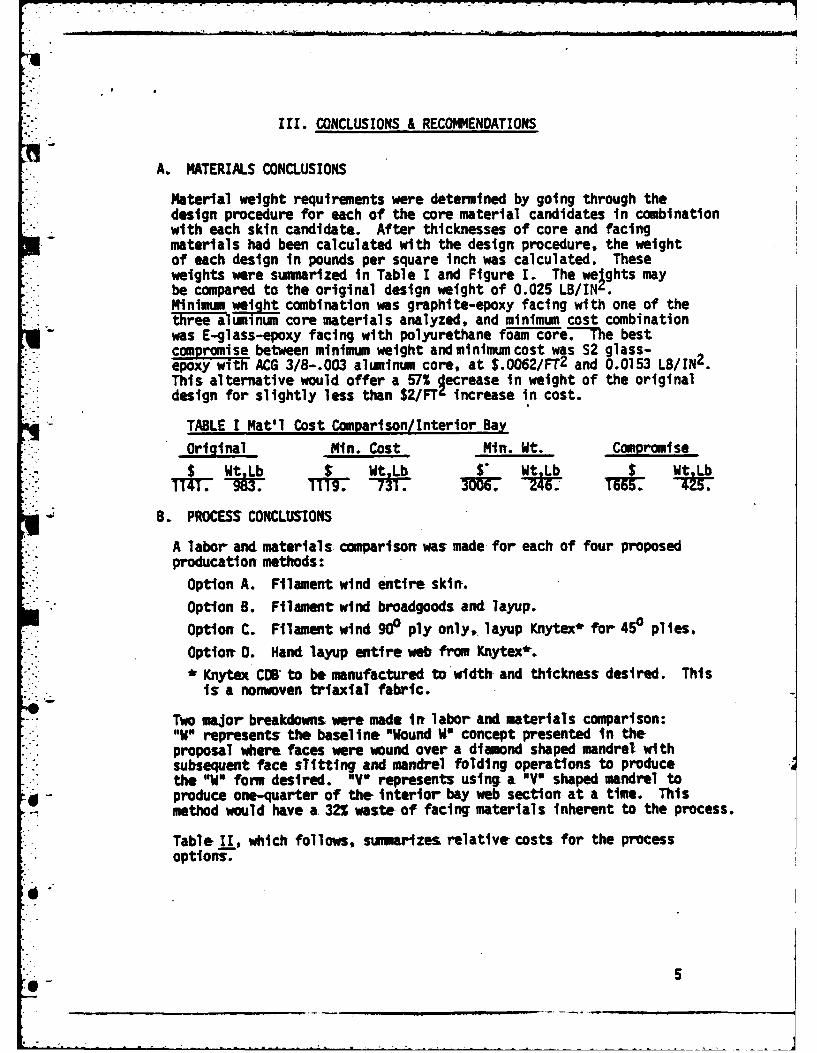
II. CONCLUSIONS & RECOMMENDATIONS
A. MATERIALS CONCLUSIONS
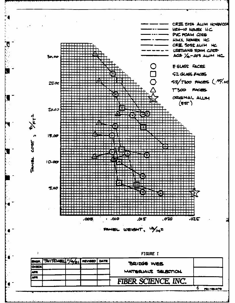
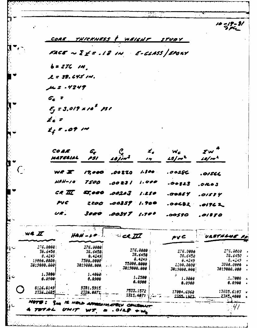
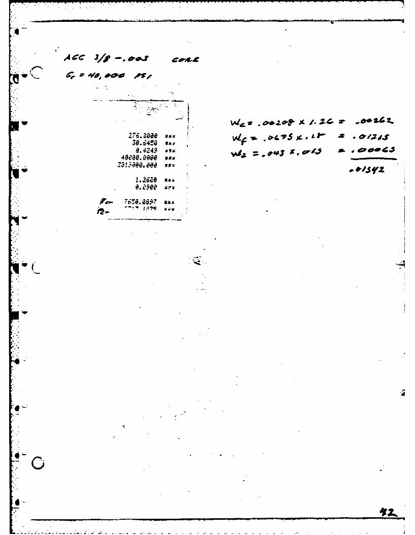
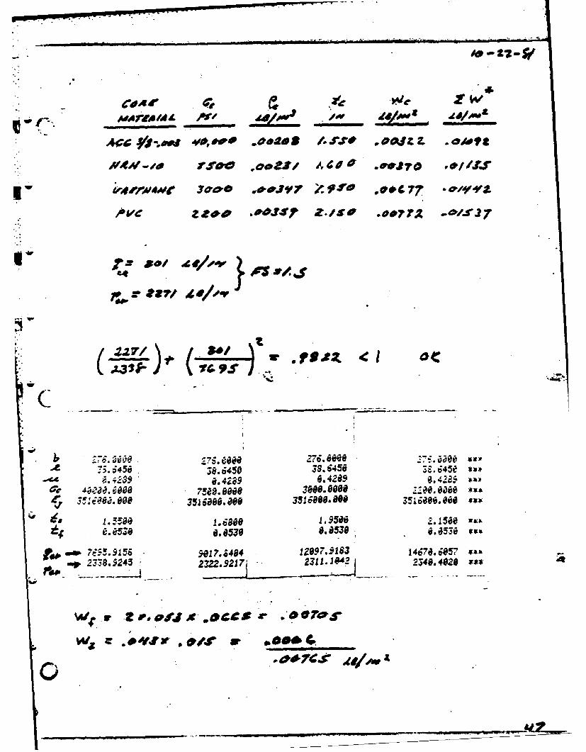
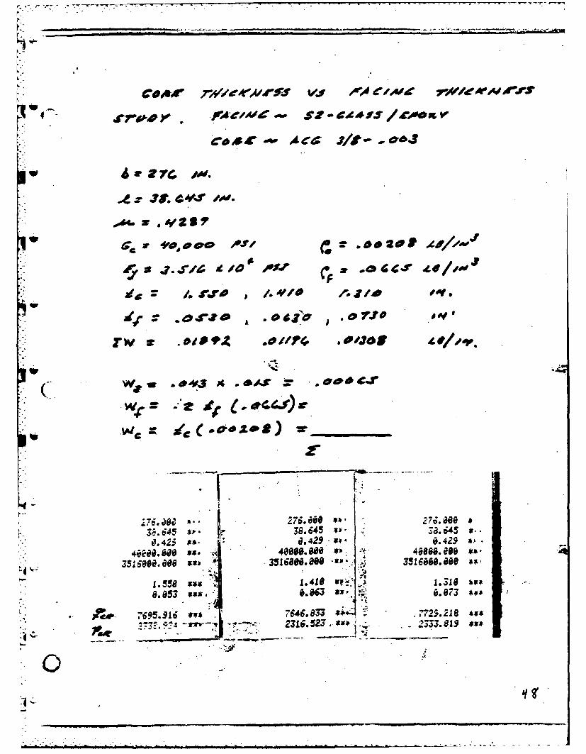
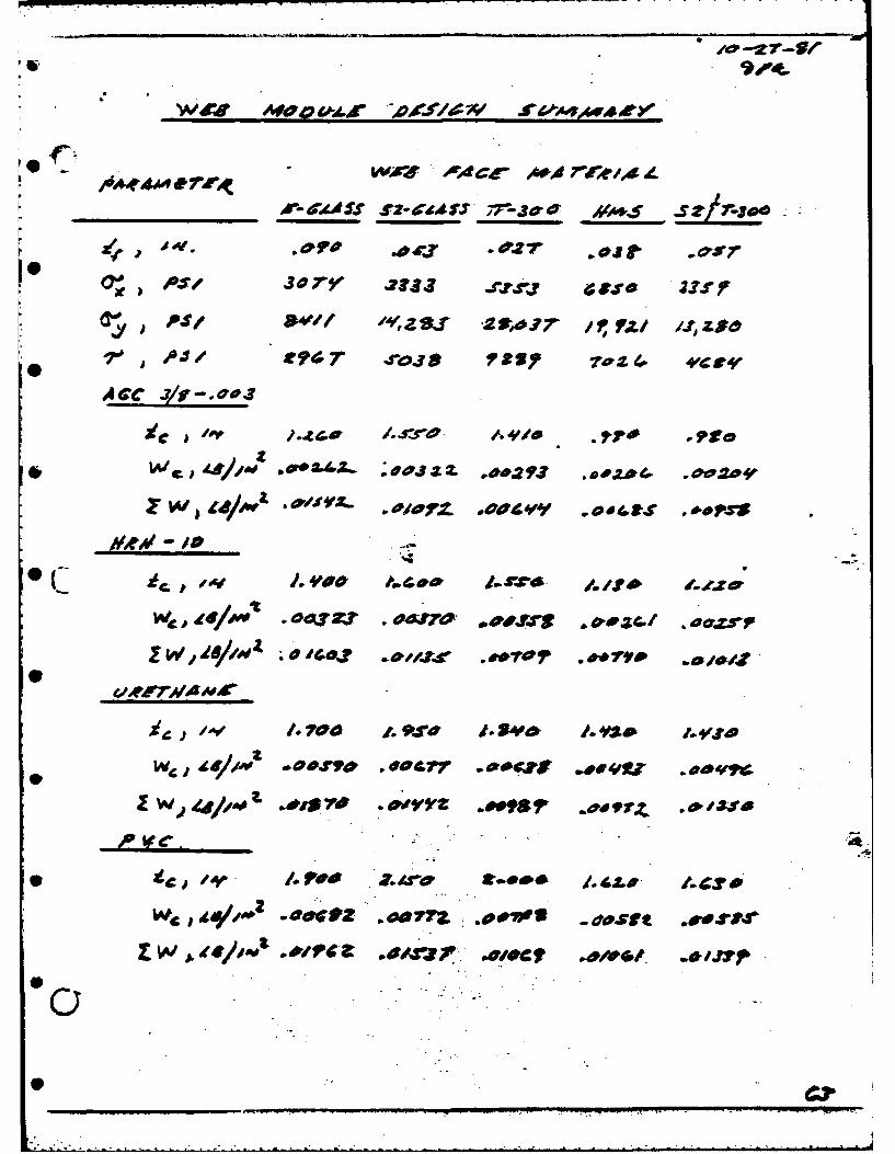
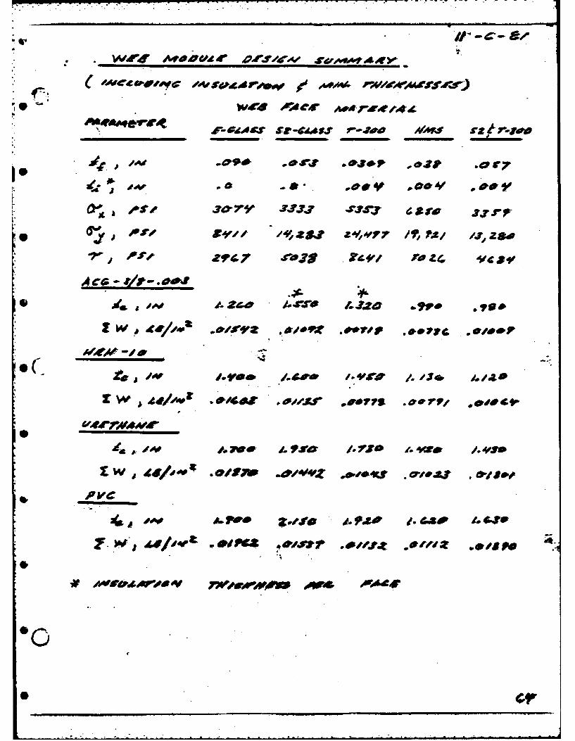
Material weight requirements were determined by going through thedesign procedure for each of the core material candidates in combination
* . with each skin candidate. After thicknesses of core and facingmaterials had been calculated with the design procedure, the weightof each design in pounds per square inch was calculated. Theseweights were summarized in Table I and Figure 1. The welghts maybe compared to the original design weight of 0.025 LB/IN'.inimum weight combination was graphite-epoxy facing with one of thethree aPuminum core materials analyzed, and minimum cost combinationwas E-glass-epoxy facing with polyurethane foam core.The bestcompromise between minimum weight and minimum cost was S2 glass-epoxy with ACG 3/8-.003 aluminum core, at S.0062/FT2 and 0.0153 LB/IN 2.This alternative would offer a 57% decrease in weight of the originaldesign for slightly less than $2/FTf increase in cost.
TABLE I Mat'l Cost Comparison/Interior Bay
Original Min. Cost Min. Wt. Compromise
S Wt Lb S Wt Lb $* Wt Lb S Wt Lb
B. PROCESS CONCLUSIONS
A labor and materials comparison was made for each of four proposedproducatlon methods:
Option A. Filament wind entire skin.
- Option B. Filament wind broadgoods and layup.
Option C. Filament wind 900 ply only, layup Knytex* for 450 plies.
Option 0. Hand layup entire web from Knytex*.* Knytex CMB to be manufactured to uidth and thickness desired. Thisis a nonwoven triaxial fabric.
Two major breakdowns were made in labor and materials comparison:'IWO represents the baseline "Wound WO concept presented in the
" proposal where faces were wound over a diamond shaped mandrel withsubsequent face sTitting and mandrel folding operations to produce
* the "WO form desired. "V3 represents using a "V" shaped mandrel toproduce one-quarter of the interior bay web section at a time. This
- method would have a 32% waste of facing materials inherent to the process.
Table 1I, which follows, summarizes relative costs for the processoptions.
:iS
C -- -C931 ZZ4- ALUM IACNWCC
- 0~P- POAM Coags
- CXL 50%J ALUM W.
AC& 4 q-O AWA4 WCm.
E- SLASC ;ACUS
Z7:oc C) 4'"Vroo FA
IIt
H *
* Is
0.L- Ir I 11V-
-" I _ _
0~ I [ _ __ _ _ _ __E_ _
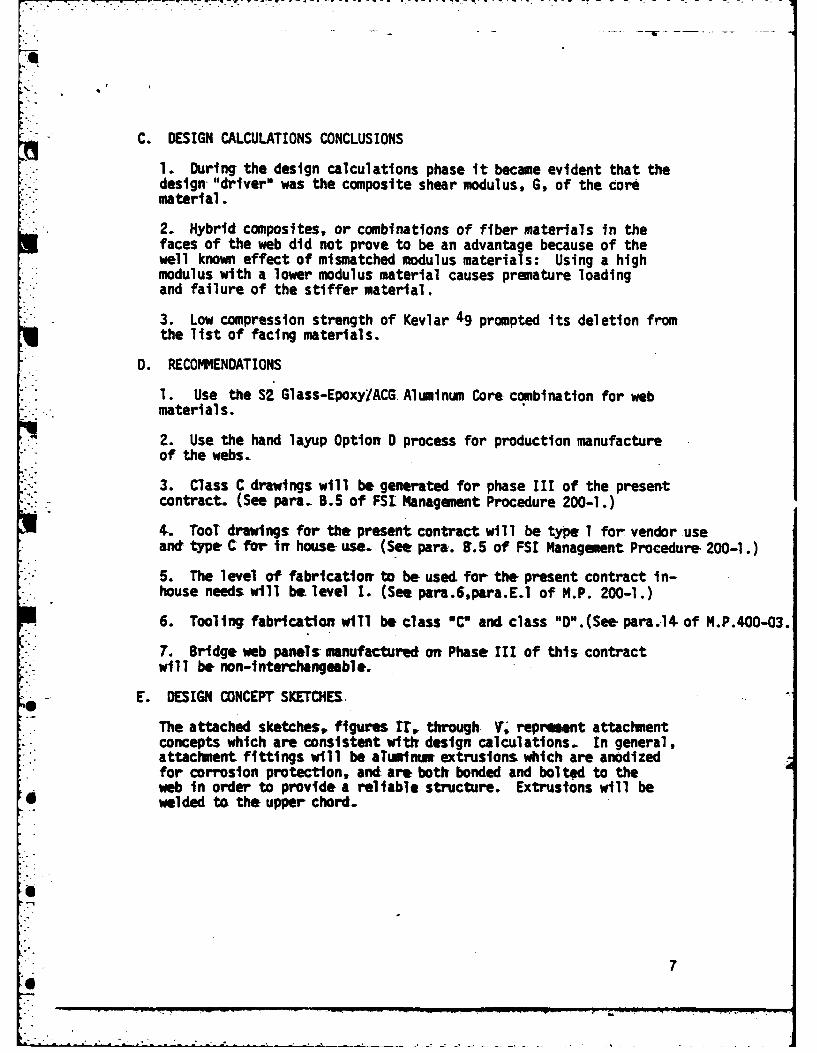
C. DESIGN CALCULATIONS CONCLUSIONS
1. During the design calculations phase it became evident that thedesign "drlver" was the composite shear modulus, G, of the corematerial.
2. Hybrid composites, or combinations of fiber material's in thefaces of the web did not prove to be an advantage because of thewell known effect of mismatched modulus materials: Using a highmodulus with a lower modulus material causes premature loadingand failure of the stiffer material.
3. Low compression strength of Kevlar 49 prompted its deletion from
the list of facing materials.
0. RECOMMENDATIONS
1. Use the S2 Glass-Epoxy/ACG Aluminum Core combination for webmaterials.
2. Use the hand layup Option D process for production manufactureof the webs.
3. Class C drawings will be generated for phase III of the presentcontract. (See para. B.5 of FSL Management Procedure 200-1.)
t. Tool drawlngs for the present contract will be type I for vendor useand type C for in house use. (See para. 1.5 of FSI Management Procedure 200-1.)
S. The level of fabrication to be used. for the present contract in-house needs will be level I. (See para.6,para.E.l of M.P. 200-1.)
6. Tooling fabrication will be class "C" and class "O".(See para.14- of M.P.400-03.
7. Bridge web panels manufactured on Phase III of this contractwill be non-interchangeable.
* E. DESIGN CONCEPT SKETCHES.
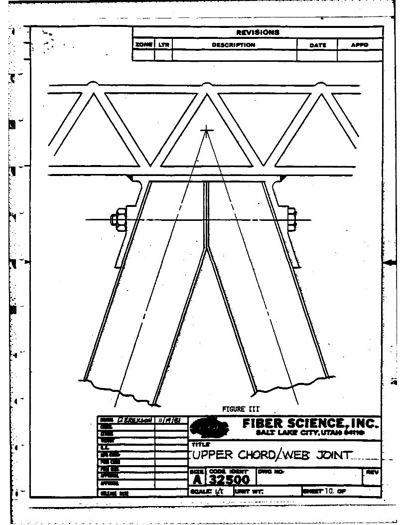
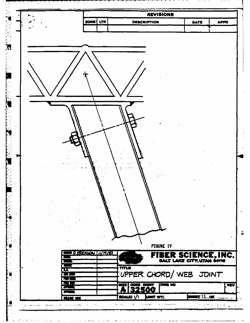
The attached sketches, figures rr, through V. repraent attachmentconcepts which are consistent witk design calculations. In general,attachment fittings will be altuinu extrusions which are anodizedfor corrosion protection, and are both bonded and bolted to theweb in order to provide a reliable structure. Extrusions will bewelded to the upper chord.
7
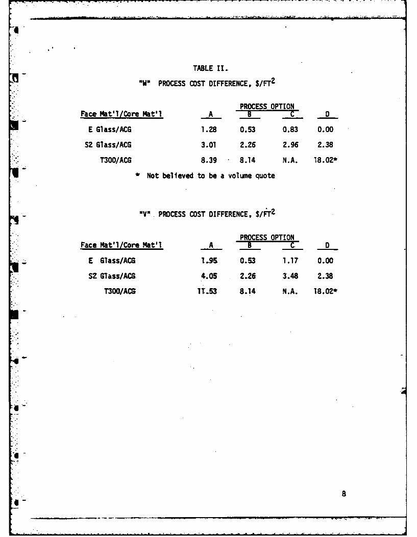
TABLE 11.
76 W PROCESS COST DIFFERENCE, $/FlT2
PROCESS OPTIONFace Mat'l/Core Mat'1 A B C D
E Glass/ACG 1.28 0.53 0.83 0.00
S2 Glass/ACG 3.01 2.26 2.96 2.38
T300/ACG 8.39 8.14 N.A. 18.02*
*Not believed to be a volumae quote
'IV". PROCESS MOST DIFFERENCE, $/FTZ
PROCESS OPTION
Face Mat'lICore Mat'l A B C. D
E Glass/ACS 1.95 0.53 1.17 0.00
*SZ Glass/ACS 4.05 2.26 3.48 2.38
T300/ACG: TT.53 8.14 N.A. 18.02*
8
* . - - -
I ELLL
p3 lb.)
pIII
ta.LI . s~.mia
3LI~
aS
I
1111i
-l
4-
4-
* I____ ____- -. -:
REVISION6
* *ZONE LTR DESCRIPTION.DT APPO
4 LL
UPPE~R CHORD/WES INU minuv
- m~ - ND-i w w wv O a
- REVISION&M oNe. LiTRDg~ os tow DATE ApPO
FIBER SCIENCINC._____ SA&X LAM Crfl'AFM 6411
'UPPER CHORD/ WEB %J"OINTr
Caa

'1l RELVISIONS
MWN L-E DESCRIPTION- OATE APO
4-
FIBER SCIENCE INC.TITLW
=' LOWER CHORD/ WEB INT
L t_ sow=,I __r_._. I/wr 12 or
-- - - -- - - - - - -- ----.....--. *~..A ~ .
WAU -4#04 -CWA 4f~ O.W.
.r1v4r4V 0 .vtro** /002' 40&7' WAC-
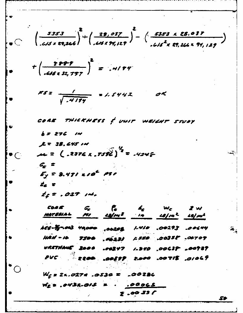
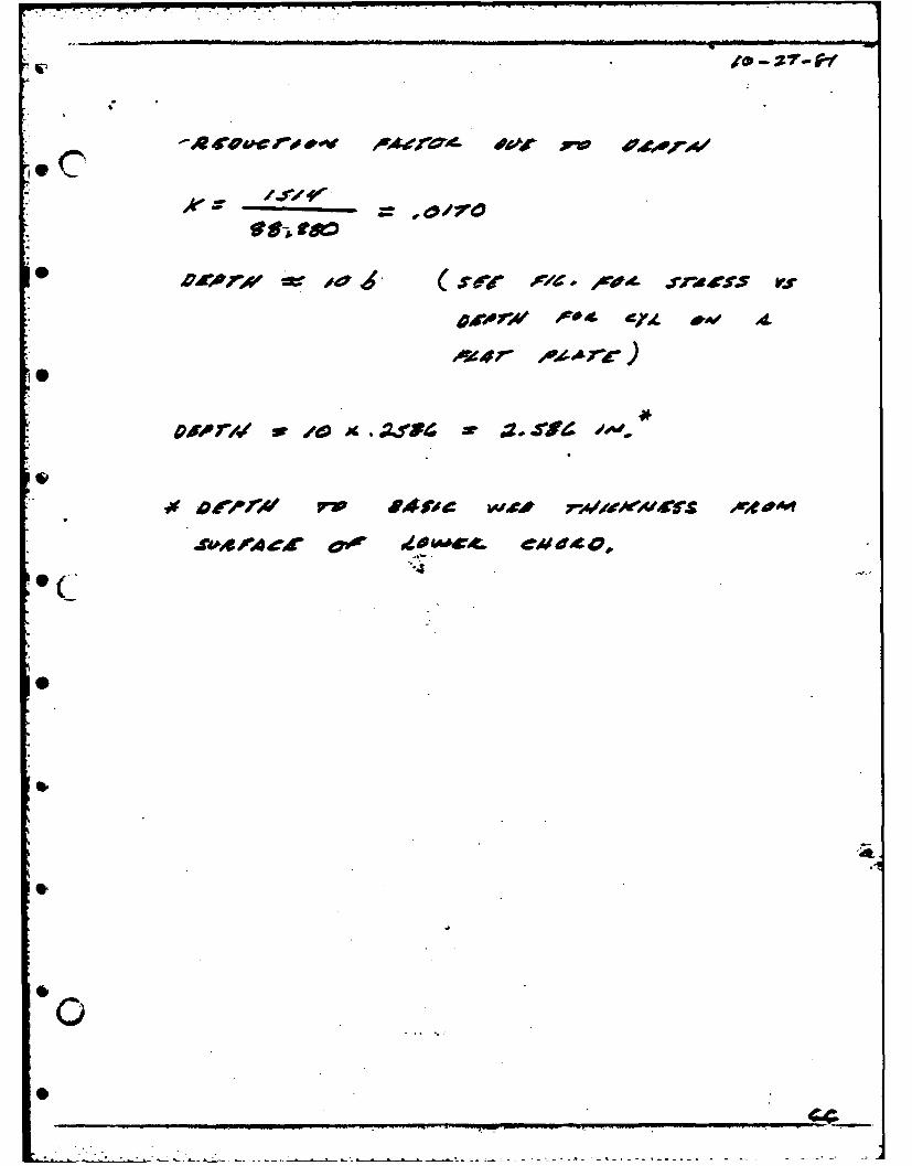
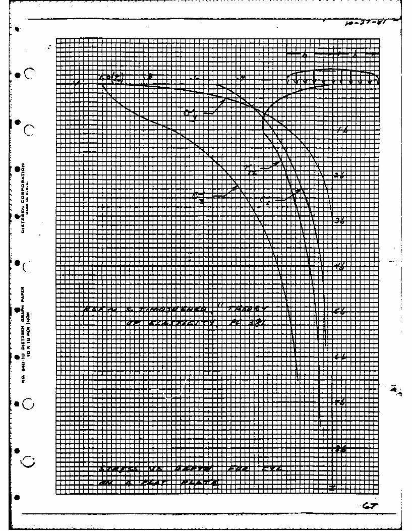
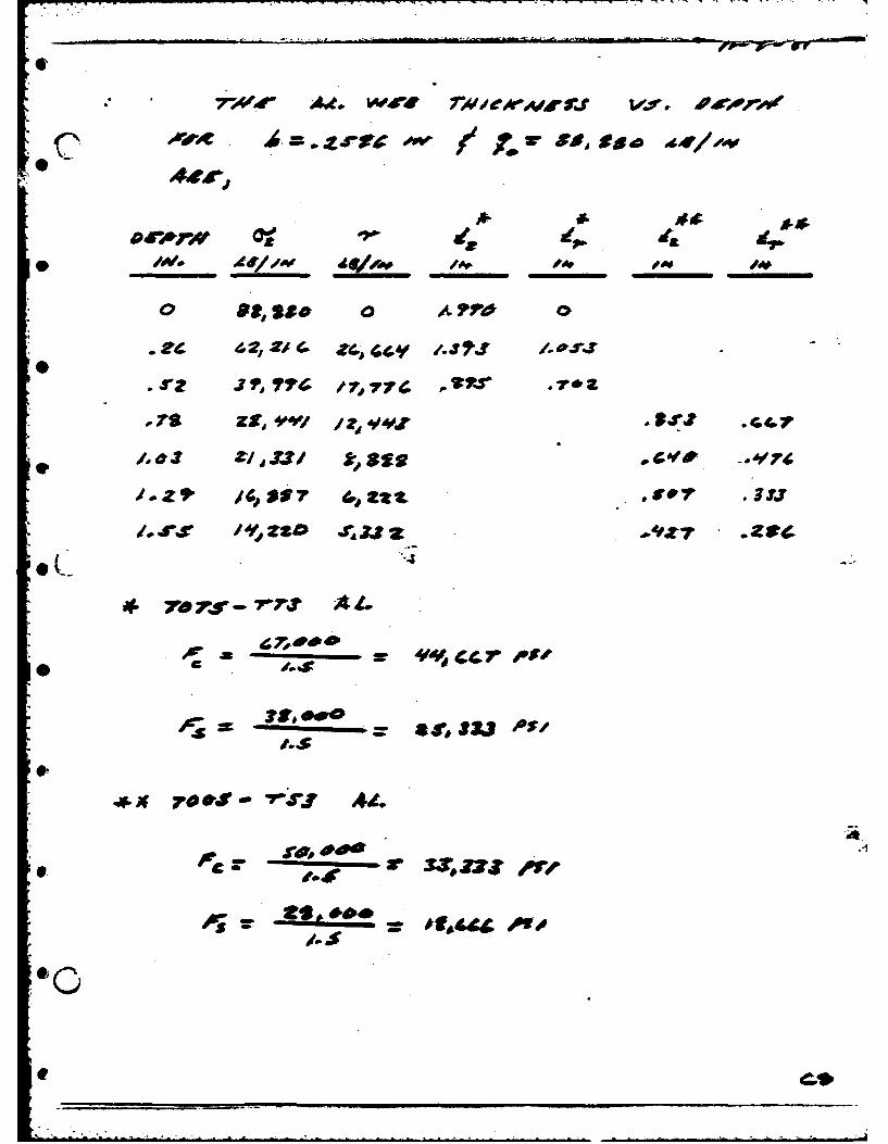
.S4#d4E -C D2 d EC e.Ur~PAAg,ce-A9*rr#iA a A49 A41O -#az
At C ?idOP4 t 7*b4~* .L~pd G/ fS C
-e&Zt i1C Ad~tO 4170 ASV A&.i
4-4
CaKS~ _9AA _A ___ A
caess 4~c' .IlaC
)CO .4 owv 40CAps, ev
A
4"-,
OU. elfolo Aeo#J'- A//li Z VO.41 M/IOX
ZA. 0 7",-doe
d~JrAI
A M~frW~/j
2Zv jzr 2V
aat
3 F-.PSA
m 4'W4/ AMP
oc VE 7 ~ 'J4' 2 ~
?,Cd-AO
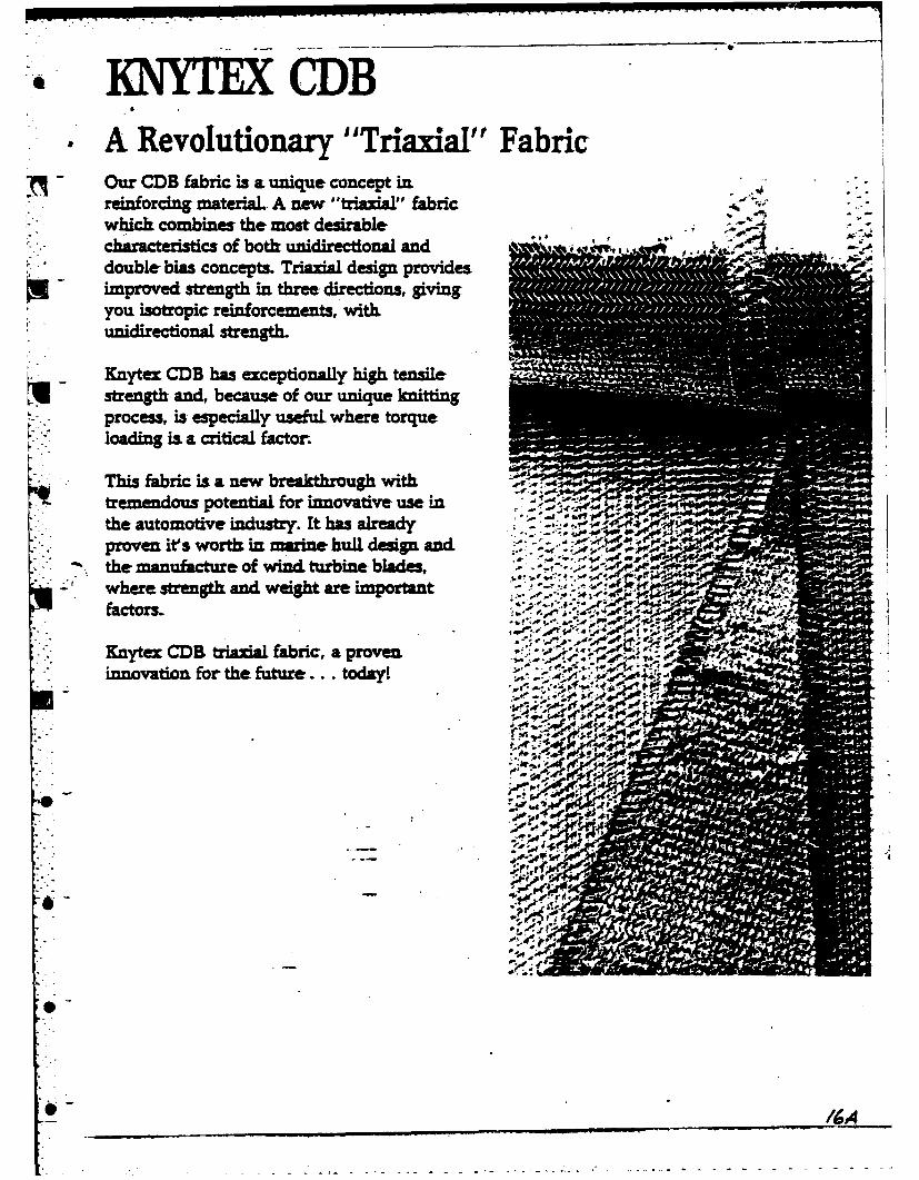
10=TECDB-. A Revolutionary "Triaxial" Fabric
Our CDB fabric is a unique concept in.reinforcing material. A new "triaial" fabricwhich. combines the most desirable
chaactrisicsof both unidirectional anddouble bias concepts. TrIauia design provides .improved strength in three directions, givingyou isotropic reinforcements, with
uniirctina strength.
~ - Knytex CDB has exceptionally high tensilestrength and, because of our unique knittingprocess, is especially useful where torqueloading is a critical factor.
This fabric is a new breakthrough withtremendous potential. for innovative use inthe automotive industry. It has alreadyproven it' worth mn marine hull design andthe manufacture of wind turbine blades,
-' where strength and weigh are important:~
* Knytex CDR triazial faric, a proven
f44.' F ~innoatio forthe u~ur... oday ;*. Vv.
J 0
* :16 A
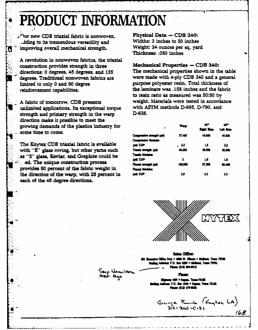
,PRODUCT INFORMATIONO w'~r new CDB triaxial fabric is nonwoven, Physical Data - CDB 340:..Jding to its tremendous versatility and Widths: 3 inches to 50 inchesimproving overall mechanical strength. Weight 34. ounces per sq. yard
Thicknes: .050 inchesA revolution in nonwoven fabrics, the triaxialconstruction provides strength in three Mechanical Properties - CDB 340:directions: 0 degrees, 45 degrees, and. 135 The mechanical properties shown in the tabledegrees. Traditional nonwoven fabrics are were made with 4-ply CDB 340 and a generallimited to only 0 and 90 degree purpose polyester resin. Total thickness ofreinforcement capabilities, the laminate was .158 inches and the fabric
to resin ratio as measured was 50:50 byA fabric of tomorrow, CDB presents weight. Materials were tested in accordanceulimited applications. Its. exceptional torque with ASTM methods D-695, D-790, andstrength and primary strength in the warp D-638.direction make it possible to meet thegrowing demands of the plastics industry for Wair *" Usome time to come.
CMPUiweil0 (1 S7.400 40160 *,Solcmpuiw Ns&VO
The Knytex CDB triaxial fabric is available (P no, * u. LS zwith, "E" glass roving, but other yams such TIemh w wo *As 315K A50
as "S" glass, Kevlar, and Graphite could be T.-,,-.,,m.1.ed. The unique construction process nol,- .* *4
provides 50 percent of the fabric weight in. _,._
the directiof of the warpr, with 25 percent in jpXl0 2x U Ueach of the 45 degree directions.
At Ma fuk *4M1 W. Mhink* Mho Tm M3WPis
--- AM= P.O. In 100, * q Tn mS
~ ~ LA)
-------- _________ . --- . R--
L l I
II
I o 1T ----
0..z
U
Ui i
?,o re 74' Z. zJt
* ~ p ia Je £
Wze 4ra SOP
3t Z&- Z,, OWA J
- O4A'P1t aJ 4Z 6
"I r
44 St
IL
iisit
w =w
tapaAU,
Lip
I0-~'a. S/
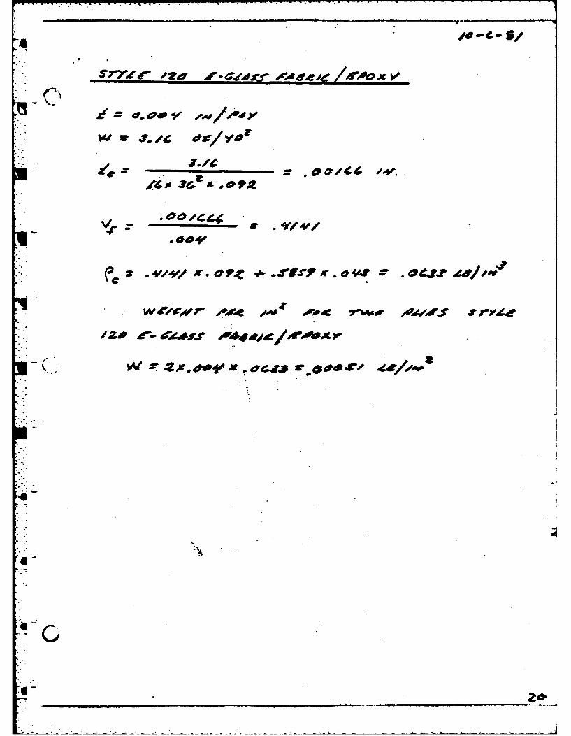
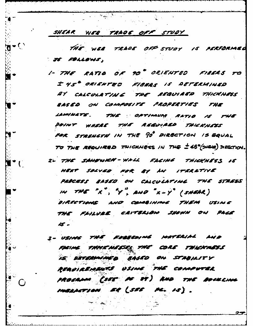
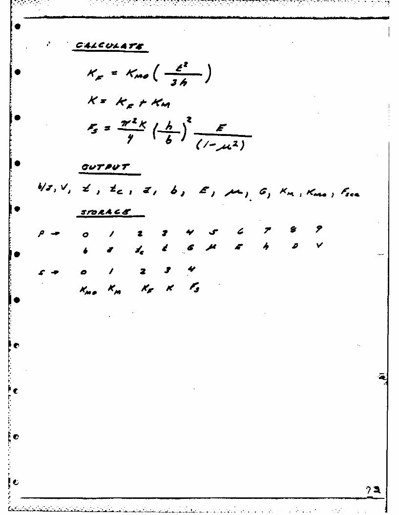
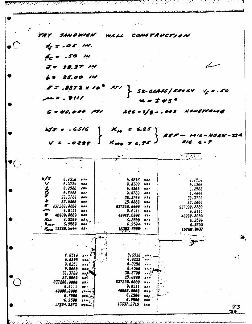
S7VZ ( /ia r- C(d.s-r "444 ie /drD0 X ~
C'- 'U.
i Z U.~.*
* * W ~ L,6
I,.,' - .4Sj~Jt~. Ad.14 a
.1~ z j~f4#f
.004'
W4~~9f 4~e "4' ~ 1'&4~d j~'dJ in rv~e
IZP £- dZ~jg V
~Ats~ ~ * * d4J3 ~
A. -
*0
6~
- . -. -U -. - ------.. ~~- U ---- ~ -- * - U
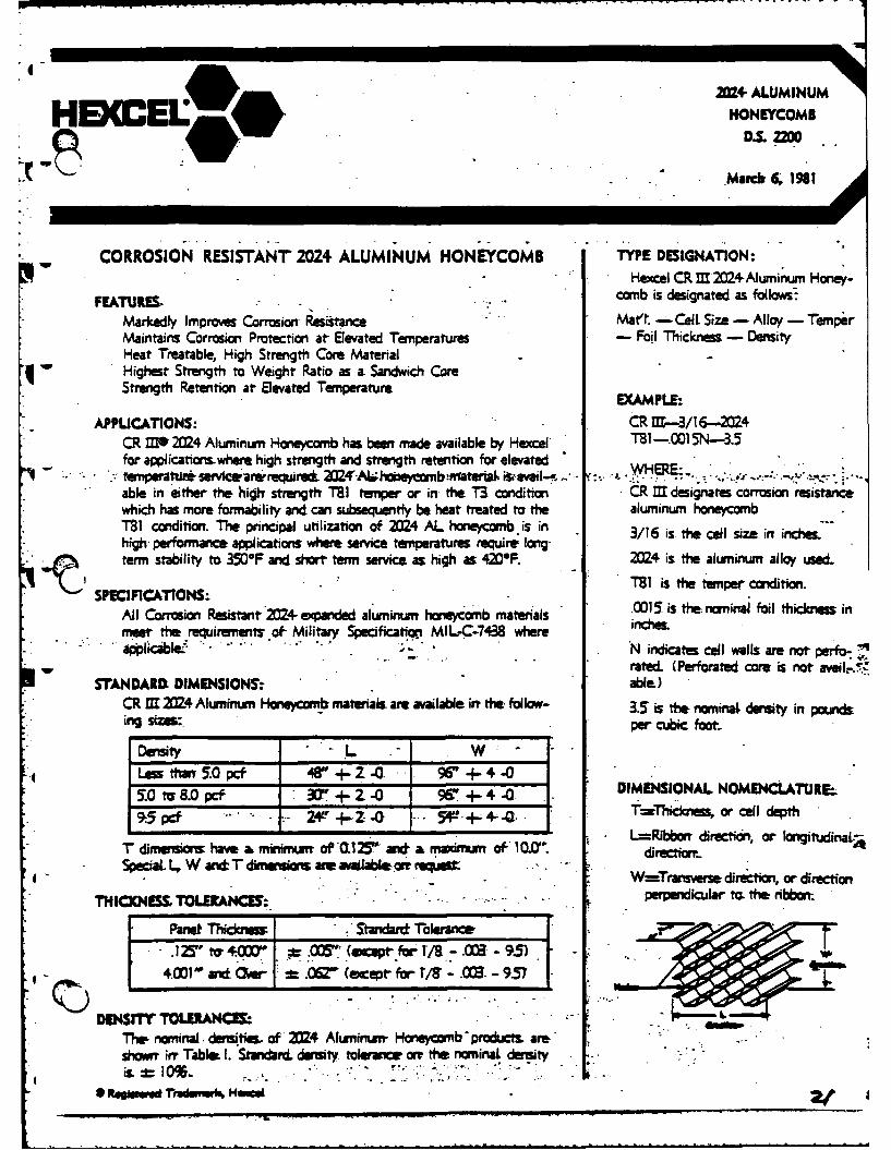
=+4 ALUMINUM
HBCCEL HONECMD.S.fO
CORROSION RESISTANT 2024 ALUMINUM HONEYCOMB: TYPE DESIGNATION:Hexcel CR, M 2024Aluminumn Honey-
FATURES, obi designated as flosMarkedly Impr-am Corrosion Resistance Mart - Cell. Size - Allay - TemperMaintains Corrosion Protection at Elevated Temperatures -Foil Thickness - DensityHeat Treatable, High Strength Core Materialq Highest Strength to Weight Ratio as a Sandwich CoreStrength Retention at Elevated Temperature
EXAMPLE.-APPLICATIONS: CR M-3/16-..2024
CR M*22 Aluminum Honeycomb has been mae available by Hexcel' T81- 1N-3.5- ~for applicationtswhere high strength and strength retention for elevated ~-~*.
.l emperai* servcearerreqWr -Alhobey mbtwraterta vl-w .,,WHE. .able in either fth highv strength TSI tempe or in the T3 condition CR M designates corrosion resistancewhich has more formability and can subsequently be heat treated to the, aluminum honeycombT81 condition. The pnincipal utilization of 24 AL honeycomb, is in 3/16 is the cell size in inches.high- performance applications where service temperatures. require long-term stability to 350F and short term service, as high as 4209F. 2M24 is the aluminum alloy use&.
T81 is t tempe condition.
All Corrosion Resistant 024 expanded aluminum honeycomb materials.01,ithnmalfltices;nmneet the requiremets of- Military Specificatopi MIL-C-7438 where ice
ippl~cabe. -- -N indicates cell walls are not perfo)-- - rated. (Perforated core is not avil
SrANDARDL DIMENSIONS.-. able)* CR M 24 Aluninumn Haweycomb materials amt available int the. follow- 3.5 is the nominal density in pounds
ing sies:, per cubic foot.
Density -L -W -
Lessthan 5.0pct 48'+ -G 9UPU ++4.-0
50 tor 8.0 pef -V.- + a09 - - DIMENSIONAL NOMENCLATURE:
915 pCt 24e +-Z - 5 ~ 4- Q T=Thcioiessor calldepth
r dimerifins hav a inimroe 03t"C2 and nmd.mn of- 10.0. L=-Ribbon- direction, or longitudinaL~i
SpecaL -. W=Transwrse, direction, or direction
TCN ESSTOLERANCE. .- * - perpendicular to. the ri bbon.
3 Z' top 00 ~ (ecept- for T/a - -013 - 95)
DENSIT TOLERANM .WThea nominal .dteus, of ZI4 Alwrninuwr Honeycomb -produCts. are.show inr Table 1. Stvxrcn density tolsurice om the nominal. densityis :L-0%.* - --.
-. .ewo . . - .-me"
*~~~~~~~ OIL~r~tad~es~M
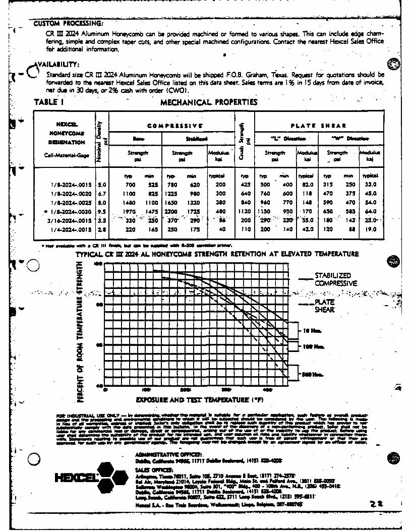
- CUSTOM PROCESSING:CR I 2024 Aluminum Honeycomb can be provided machined or formed to various sham. This can Include edge cham-fering, simple and complex taper cuts, and other special machined configurations. Contact the nearest Hexcel Sales Officefe additional information.
AVAILABILITY: 0Standard size CR M 2M24 Aluminum Honeycomb will be shipped F.O.S. Graham, Texas. Request for quotations should beforwarded to the nearest Hewel Sales Office listed on this data sheet. Sales tens are 1% in I5 days from date of invoice,net due in 30 days, or 2% cash with order (CWO).
TABLE I MECHANICAL PROPERTIES
HECLCOM PRLISSIV r PLATE SHEARHONrYcoME A ... ______ -- . . DI.,ue. 'w' Um,,,w
now kesio orW DkessONUIGNATION _ _ _ _ _ _ _ _ _ _ _ _ __ _ _ _
CuII..Matsrl-GWg & Woodig Si 00 Moduks i& "191ng Modulu Sivmigth - ic~s
RI m t w mm typal t rnL4 typical t mm t
1/8-2024-.0015 5.0 700 525 780 620 200 425 500 400 82.0 315 250 33.0
1/8-2024-.0020 6.7 1100 825 1225 960 300 640 760 600 118 470 375 45.Q
1/8-2024..0025 8.0 1460 1100 1630 1320 380 840 960 770 148 590 470 54,0I -I.8-2024-.0030 9.5 1970 1475 2300 1725 480 1120 1150 950 170 650 585 64.0
3/16-2024-.001 3.5 '330' 250 370-" 290 8 200 "P': 2 S'S.O 18 023
1/4-2024-.0015 2.8 220 165 250 175 40 110 200 140 42.0 120 8 19.0
• Not egedomw wiWt & " Ul fII & 1k l Owco be iw i wilt ft-NO nwml" R tnm o.
TYPICAL CC E 2024 AL HONEYCOMI STRENGTH RETENTION AT ELEVATED TEMPERATURE
- - a- -- - --- ---- STAB IU ZED
- -COPRIVE-l " " -, -.. - a -• - - -
IMU
---, .a a * a - * - - O..._. . ..T. .-
- af 1-" HEA
i ~~ ~ EW ,-R•E l AND Tff TEMPERAURE (OF)
do~~ ao "W -www an -wao aon -v WO a o 130 a-W &W -- ~~db Mu. 80 - isds
aw* *ff aw aM - a af aulo I* aWOew-" - - f a AM a~ d"ab
M aa aa=..-aa aa
a w a k aw* a114 Lasi F.w 11- aos aL a" -~e avs (31 a Waa
t , Sp 8NA,- Q 45 5441t
OP6fUINIskr ITTIMRATUR (11- o ,ulkiue* i401 SAh'sgy ib, Iul et riuin0 A a it. 1817y * w m4tW.1a lm71ew.
Lnnk , CWW&M 11t&M1 1 OLw* km*m~i Wtv(23511
MO gn ra . l j k~ Wdhower Usem kkiss 0174004F- UWU lnel R- ... "4 -e ii ldj i aoi"ll aie m
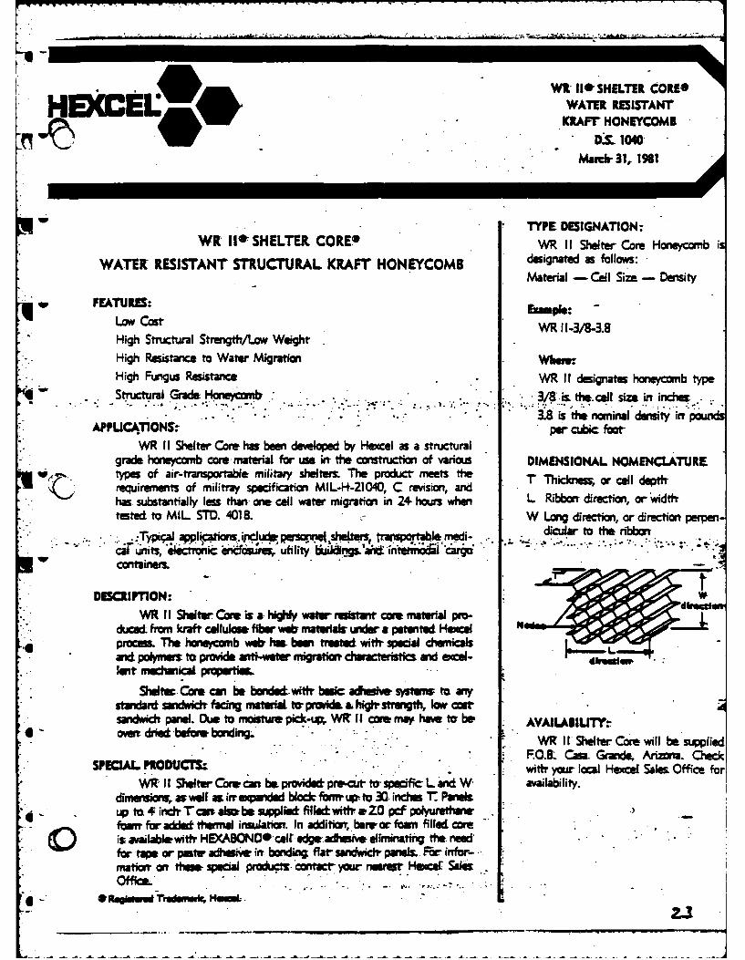
"'If ISHELTER CORE*
HEKC(EL WATER REISTANTARAFT HONEYCOMB
TYEOESGNATON:
WK IIWSHELTER. CORE WR 1 Shelter Core Honeycomb is
WATER RESISTANT STRUCTURAL KRAFT HONEYCOMB deignate as follows:Material - Cell Siza -Density
wFEATURES: Eape
Low~ostWR 11-3/8-3.8High Structural Strength/Low, WeightHigh Resistance to Water Migration Whava:High Funigus Resistance .WR It designates honeycomb type
St uctral .... -/8is the. cell size int inches.aa he o~inaldenity iwfpud
AFPUIC4T1ONS~ per cubic footWR I I Shelter Core haff been deeloped by Hexcel as a structural
grade honeycomb core material for use irr the construction of various DIMENSIONAL NOMENCLATUREtypes of air-transportable military stieltets. The product- meets fth 'r Thickness; or cull dett-requirements of militray specification MIL-14-21040, C revision, andhas substantially less than- one cell water migration in 2+ hours when L Ribbort direction, or widtthtested to M IL STD. 4018IL W Long directi, or direction perpert
I* meddicular to the. ribbont.Typi;alapplicatiui. ipciud pwsuI *shefes trisportabe mei-
cal units, icr~ c iieifsutes, utility ii;"dgs d i~~~ caro
DESCM1PTION: WWR I I Shelter Came is a highly wawteion! core material pro-
duced from kraft cellulose fiber veb, miate ra wder a petented Hemeel of* process. The honeycomb weir ha bewetreated with. special chemicals
and polymers tot prAove anti-water migation characteristcs aid scal-len mecal prpea
Sheltec Cars can be bde.wi*f bole adheshe systema to anysts drdu sndwidchfngmateraLt provide, aht-ightegth, loas Atsandwich pae. Due to moalde, pik-up, WIZ II core may hae tar be AVANLAgIUTrrho4 oEdried bfna boding.'
W1R ILI Shelter Core will be supplied~ PROUCI ~. . .P0.8 Casa. Graide, Arizona. Cluck
WIZ I I Shelter Corer can be. provided pie-cur to- spe~af L and W ailcal Hc alsOfie odimeruioru. as walt a irr w;endd blo& fbmup-~to 30.inches t Panelsup~ to 4 inr Tcw &I=be upplib& filhd with, &ZO pcf polyuirehanefoarrr for added themial insuation. In additiar, berreor foami filWed CamCis, availablewitl HSCABONOcelr edge adhesive elimtinating tt edfor tape or posts, adhuise int bondit-4 flar sandwich paniel. Fr infor-matia" on ttmw -pca products contact- your neaer Hecer SalesOffice....
I ~ ~ ~ - - - - -----t~n~r H
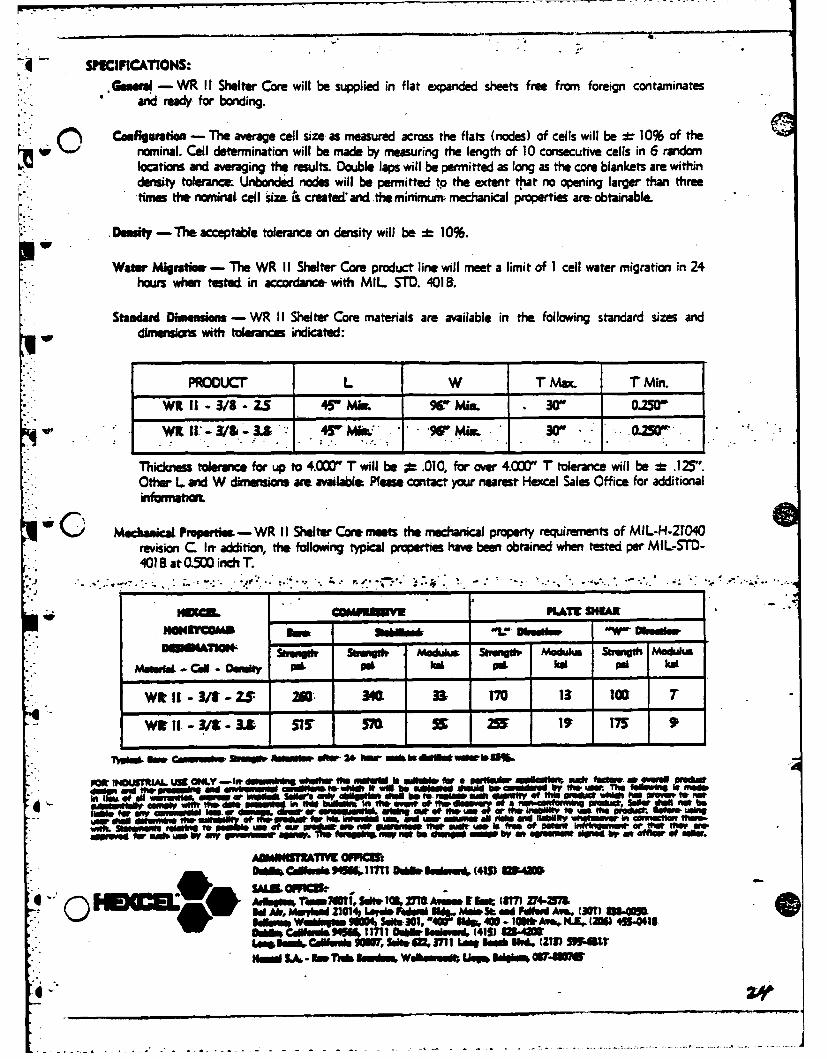
4 SPCIFICATIONS:Genwu - WRItI Shelter Care will be supplied in flat expanded sheets free from foreign contaminates
and ready for bonding.
~jComfiguratien - The average cell size. as measured across the flats (nodes) of cells will be :g 10% of the~ w "-'nominal. Cell determination will be made by measuring t length of 10 consecutive cells in 6 random
locations and averaging the results. Double laps will be permitted as long as the core blankets are withindensity toleracL Unbonded nodes will be permitted to the extent- thiat no opening larger than threetim the nominal cell size & create& and the minimum, mechanical properties are- obtainabhl
Denity - The acceptable tolerance on density will be- *b 10%.W
Water Migratiwu - The WR I I Shelter Core product line will meet a limit of I cell water migration in 24hours when tested in accordance- with MIL STD. 4018S.
Standard Dhmeasious - WR I I Shelter Core materials are available in the following standard sizes anddirnwaon wfth tolerances indicated:
PRODUCr L W T Max. T min.
WK 11-3/9-Z.5 45 Mim 9 min . X30 0.250
Thicknms tolerance, for up to 4.0=0 T will be ;P .010, for over 4.0(r" T tolerance will be :L .125".Other L and W dimensici are available: Please contact your nearest Hexccel Sales Office for additionalinformn~a
~~ C Mechanical P*Merie - WR IIShelterCoremeet the mechanical property requirements of MIL-H-2T040revision C len addition, the following typical properties have been obtained when tested per MIL-STD-401 El.at 0=0 ich T
Ham=mw KLATZ SNEAE
-o"TO -vi Mo" 51woogd Mam Swt Modu
Molr- -el - -ON -I -e -41 O dP o
wt I-W9 - ZS 20' 340L 3& T70 13 100 7wi- -t-/ - -. -15 -S -59 15
rjiminea CmSW~ 200100 404OW 2+w VO 91@ b IN ~ tW~Iget53-
PW *40IJIIA6L U1 ONLY -I* Ids Isihrli ~W or fa alkn a= e'uw a' A w * moffame, W 1 guei
Wt dullVA" ofsoh' temUl eraw letW Mto W~ 9MUM, - § we Mo It ftWStEW i l Of~ht ukoMENWur "WP m "utue WW
wud,. Setm~e ul~W woCmu Thns& MI e 10 MA ma~ - t f Cut (87 iu-Mfvn~u-o etmr* ave~~in let md ~ a Ak WV iss eiiuo 2114 Lavie re bsdhee muse 5L an Fiediim M46 m UQD a, slM o
D~~~~ Cmbsumi DII. Iedsuev46 (415) 91942
Hoo L, ra~uf is 1 5. Waksve im @19 (30% z4.aT
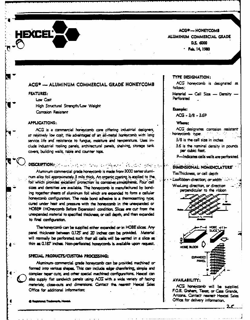
ACG*'- HONEYCOMBHECE L9* ALUMINUM COMMERCIAL GRADE
W DML 6000Feb. 14, 196
w TYPE DESIGNATION:
ACGO ALUMINUM COMMERCIAL GRADE_ HONEYCOMB ACG honeycomb is designated asfollows:
FEATURE: Material - Coll Size Densty -LOW CatPerforated
q ~High Structural Strenigth/Low, Weight Bape
Corrmon ~tantACS - 3/8 - 3.6P
APPLICATIONS- whaw.ACG is. a comnwiecial honeycomb. core offering industrial designers, ACG designates corrosiont resistant,
at relatively lwcf, f-advait fa l-nea o~c wittf I~' -tpservice life adresistance to fuigis, moisture aid tunperature Uses in- 3/8 is the cell size in inchesdlude industrial tooling panels, architectural panels, shelving, storage tank 3.6 is the nomninal density int poundscovers, building walls, table'and couniter tops. peiC.bic four-
P-4ndicates culls walls areperfarated.
DESC1PTIN~.- . ~ . tDIMENSIONAL NOMEN4CLATURE'Aluminum commercial grade honeycomb is made f raiw 3000 series-alum'n- Thdeorcldet
nuni al loy foil apprm~xirately3 mils thick. An og=4c atifiis applied to the, .hcns, rcl et
* ~ ~ ~ ~ k wdrrod le protecion'ta caosuiw atnispheraL., ~rcallsizes and densities'areavailabl& .The honeycmb .ismnfactu~red by bod W=Log -direction, or directionrig, together sheets of akmnmnurn foil which are acpandied to. form & cellular perpendicular to the ribbon
honeycomnb configurationm The node: bond adhesive, it. a theirme!tin type;cured wideir heat and pressue with the honeycom in thet uneipnde orHOSEP (HOnwfcomb. Refore ipuin) coidifion Srice ame cut fromt theuneianded material ta specifiled thkicknss, or cell depth, and then spandedto final connfiguratkim
The I a eyw omE cani be suppied either eiparided or irt HOSE slicm Aeuiyr- NNSE -~* paiel. thicknessr betwme O11Z and X indwe carr be Pvide& Material
will normally be Per forate sudr that alt cells~ wIl b& vwited iwr a slime as4thin Q.L19rindie Non-perfoarated' honey=6m is avalaWl u~porr requestA ;Z e.
SIPEJAL PRODUCFS,'CUSTOM PROCUSSINQAluinumn conmercaL grade honieycomir carr bir provided madineif or-
* formred intar varlas shapes Ths cw include edge- dufrng simple andcomnpl taper cuti,. anti othew secal machined contfigiurations HecanC also supply flat sandwich panels usin ACG with. a wide. variety oF- facing VIABLT-materfais cloe-outs andf dimensions; Contact the. nearest Hecel Sales - honeymbwlbespieOffice for additional informnation: F.OB.Gr n will~ o e asupGlid
Arizona. Contact- nearest- Hexcet SalesOffice for delivery information.

* Standard Dinwasise:Hexcel's aluminum commercial grade materials are available in the following standard size:
Unexpahded L (HOBE): Expanded Dimensions: Sc:T Ft lPer Panel:6 I" ,18-+Z'-0"L x I"+Z'-6"W "
One of the. major advantages: of the- ACG product line is the availability of a structural metallic honey-comb at low cost. This is posible because the product is made in only one panel size and is shipped un-trimmed as exganded While variations in '" are available, the "'" and 'W' dimensions will only be suppliedin the expanded dimensions shown above. Special 't. and 'W" requirements or pieces cut to size can besuplied upon request but may carry a. premium charge, depending on volume.
Tickess Tlrance:Tolerance on cut thickness are as follows:
P"Thickness Standard Tolerance
.1;5S to 4.=:D .008"v 4.001" and Ovw- ! .0sZ"
Density Tolerace:The standard density oerance on the nominal density is : 15%.
Me . .ieo --tI ,str oO. ". -., ,
ACG honeycomb has bee teted per MIL Std. 401. The following typical properties apply:
NEN .* POMIISSIV9 . PLAt SHI A&
OW COPS lo. ... " :.DUINAT@W -ho, 5Wo OA -O1h -ok lo-
• ,.. - siosdu I ~i , ,.
AC1/,4.~ SW* --T. 340t * 4 . 241& *241tt .. 1 31ziAM e 2/86 3A m 340 . 2 2106 * u 2W
AM3/4,M 1., 96 Ila 24 45 ts 1,, St OrACM .W 1 A W1 P.4 2 Ul 2 S " 1. 441P 7
Tested at M5 inich'tdme. p- prelmina y values
SFOC INDUSTIAL USE ONLY* The following Is made lt Hem of alL wazzanUW pn or hmplied: Sellers only obilh l ot shall
be to replace s& quan~t this produft which, has novm to not s ay coply with the-. his beMla fL tho. evmt of the discoar of a n onf-orl g produc, I e ll,
sha not beUablk for my-commerial. I= or damage diet or u al, ahd out of theum of orthe ibil~t u to u*th pauu g uaw shall detmne the siitabil of the
fproduct for big. Intlded u aand uumm Ual. k and. liability whatsoeve in connectionthwwih.Statemaits~ reletfne to pWONbl usm o oa= product are not Suarantees. that such use is
fme of patmt inthi ne t or that the- ae a ved for such useby any gem ent gene. Theforgoing may not be chagWe29d pt bCEO agemnt signed by an e o se .
ADMINSIAT1E OFI MD4MhF&C'"f_:k HUfo.11711 DOiDh ldms, (415) 04L
I ~,T m md it, 5 idb I D 11~~m £ l iiiii (317 3,,dill3d Au Mym 11,L'I ~d Mobe St~ Wd FulON Ane, (301) 30-055......... 108Wa USmh31.--~ Am$., NJ., (20)14941%
I~ I Calmuls 305"d 4M 3711 Lim9e@ u *,, (231) 35.611N" L,,A. -iTuuk ImN...WlOMdut U"% k M W107i
* 2$
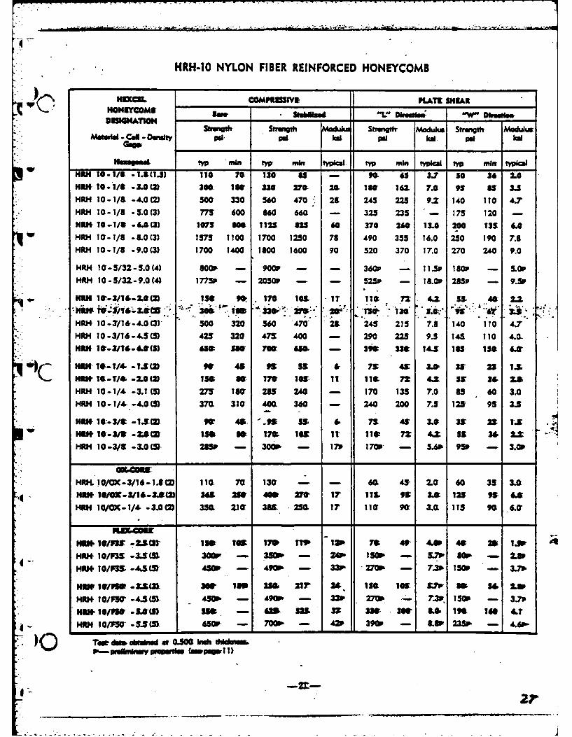
HRH-1o NYLON FIBER REINFORCED HONEYCOMB
HIXCI COMPSUSWI PLATE SHEARSNCms Shabwd -W DkHONeEwc S W DkesebwDIGiATION.
Sirmig Strength Modul S!vigth- Modulus Strength ModulusMoi.4d - cll - Oety o pal r a pl hd Pat al
Ntyp mrin tw min kilw tyv min typical typ miw typicalHiJl 10-1/1 -1.3(1.1) 110 70. 130 85 - 90- 6S 3.7 50 36 2.0
HER 1O- 11 -3. O(2) 30S 1W 330 270. 20- 150 161 7.A 95 a S.5
HRH 10-1/9 -4.0 (2) 500 330 560 470 28 245 225 9.2 140 110 4.7'HRH 10-1/8 -5.0(3) 775 600 660 660 - 325 235 '- 175 120 -
HPl 10-1/S -6.9(3) 1075 301 1125 625 60 370 260 13.0 200 135 6.0w HRH 10-1/8 - 8.0 (3) 1375 1100 1700 1250 78 490 355 16.0 250 190 7.8
HRH 10-1/8 -9.0(3) 1700 1400 1800 1600 90 520 370 17.0 270 240 9.0
HRH I0- 5/32 -5.0 (4) 800P - 900P - - 360p - I 1.5p 180P - UP
HRH 10-5/31-9.0(4) 1775P - 2050P - - 525P - 18.0P 285p - 9.5P
HIU 1W-3/14-24() 1 9ISO 170 105 It 1 72 4.2 S. 49 .
no x2~f 306 ia 33W~2 20' 7 130 .@. ~ 6 .HRJ 10-3/16'-4.00) 500 320 560 470" 28 245 215 7.8 140 110 4.7HRH 10-3/16-435(5) 425 320 473 400 - 290 225 9.5 145 110 4.0-HEN I -3/T-6.(S) 65: S0 70W 6S& - 396 336 14.5 185 ISO 6Z
.4c %RK- 160-1/4 -Ts(, 9w 45 99 59 6 7V 49 3W 39 23 IX
HI1U -19-T/4 -2.0)() I& - 171W lO' it 110 72 4.Z St 34 r,
HRH 10-1/4 -3.1(5) 275 180 285 240 - 170 135 7.0 85 60 3.0HRH 10- 1/4. -4.0 (5) 37(L 310 400L 360 - 240 200 7.5 125 95 3.5
SHm 10"-3/t1 -1-. (= ft 45 '.95 55 6 7$ 3. 3W 22 I'. .
iRt 10'-3/S -Z(5 ISS I0 17& 105 It li 72: 46 55 33 2.HRH 10-3/8 -3.0(5 235 - 3009. - 179 17W- - 5. 95P - 3.P
HRI 01/C- 3/16 - . 10L 70 130 - - 60 45 2.0 60 35 3.
Hill IG@- 3/1-34() 365 2W 400 27 IT 115 9 3Le 125 99 6.
HRH 10/CDC-1/4 -3.0(2 350L 210 3W0 250 17 I10 90" 3. 115 90 6.0
INUN l/P -Z(3) 1M I16 170 IP I 7& 4- 4.0 4: 2 1.
HRi+ 10/P3= -3.(5 3009 - 3 - UP9 150P 5.71, 80 - U
HRII 10/03 -44(5 4809 - 490P - 33P 270 - 7.3 150 - 3.73
Hiw Uf/PUS -5( 366 18o 256 OrI 24.. ISL I M 9 M 5 4 1.Mm+ 10/F50 -4.5() . 450P - 490P - 33F 270P - 7.3p T50 - 3.70
Nll H I1/vW Ld.0(v SUS - 62& 525 3Z W 336 LO6 I.S 1"16 4.t
S... HUHI 101F' -S. (5) 659 - 7009 - 42 390P - 3.1 235P - 4.6,-
Tw dam bnd at 0.00 inch -I I
(), - _ulin (ap_ 1
-
4 -- A -r)
A,,. SfI.. opo * 'd W )
4~P~~D~DD* #4t (ub/dJ,)
4w I dJ * i/0 opse
4 i"
'JL
t~zt
7~~fo4ov-r~t AL trlAsO.
IrI
, L?/Ous
heyh
- A.CoA
4-o
0WA
A"A rj M",2,
* AMA1AMO
w ~ AA r~*WJ cPiO.0- COV*,rX jJ#j 4 ,0 W
A4~ A S 4rA c r# foeV w
-A-,ds
wLF2.
14.VC 0"
/40
2,V
n /S~fI JTZ9fwf/41Z4' COS$ft
,FOG A4X1A
* ( *4P.e*4 *74~ia*TC.MD
A*A#4mw Ojfr)V9AA* WS"w S '4h*C* pI
~r ~ p44d 4*.3r#
Ar 14 r~m ldod8po
Cu..
,4t ~~ ~ ~ A /P4oo* og*0 4 C bAA fIA. L
2"o~ ~ ~ ~ 49r/* APn FA
C C40rAA 4.#4-C OeAAP IC -AP)
2- -;r
7~~~ ~ ~ 2s'f -- t 4' fo r
IDr
JA
C-ftIdCAs. C0,4Aot"A Ao49 rSjp,*A dvcCjoAoj
di4 SA I fI
.04..
J~4tflCOP"
.0 i o r
:AO At.~J(
C P*~ ~*44'W~ ~4 ~( 7'"lamb"-
rd O *'sOf " 1
- 4ZA-fP %4 X4O._AJ-.C%'4~rA rO& ~l
4 WaRCri" 7IdZW~V Ai .v
~t$~4 ofo1-vc4P jo#4*V
*e A#* C,*'of -90*-J
A :zo 45
*~rtwD* -A00
4x27'q7 pa a,~ raw..~~ir
6 ~ ~ OO~OO.or ~ V VL 7.~
7~~' ~'J7;At C,&;e4 lowr '
MIN 7wr~ Or477W*1o OD4ov Av 7--AWA $ 7IV
OIAOWV4V. *.~ 9VA **7 4 *'*"-
Pd'~ ~ ~~40V r1- wV* -d %45 */Z rA~g2
AUVO v
~C . i~'r 9 p~aC~iOJ / Bq''AL
..'**.~*- . . . .. ..--
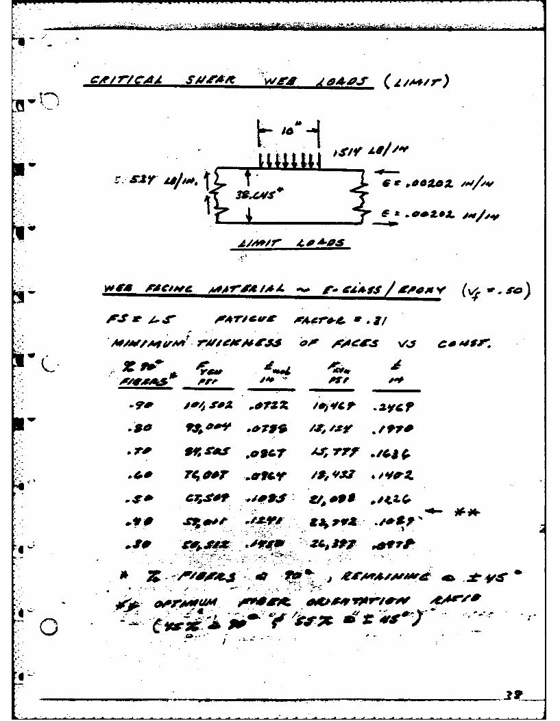
c4'/77c4 ~wi'~ wj06WsIII e,'.'r
Aollov.
**o 1404
W " r~wtv * A /MAe1 r C.44P s sx/ #00ev (V' ro
AfV1frTr~~O4A iPrA4. . oASF
pr 1
04Wo OR$ vol vo eA
......... ...
70R Y /Jr I-VCd A Sf /Z-,000
7,CZ 7
2'9.
1*0 2 4 7 /f/ r?
+___ C J, 72 2
3G-f __A_____*&#f o 4 A
ow3
'c rm/P ~ d
A$W J.
- ~ ~ '5:.~ - .-- - . - - - -- - -- ~ -- ~ ~
- -
"#4WC.
I -
~J L*fj*u \ cJ-~ £24~
V
1~3'0
V eaer~~A' d~p ~If v~5. 4~
7~. C~ ( Z27/ / S/o : VUt, c ~I .4/
I
~ ~
e I.~ ~'
e;~G .~..
V~.-.J.~LZi85dflcAI
I-.
- CPM/r wavg.*'f CA4C~~4At/D#S$
dVACtJ~~~ *OG74g'./S x ~ Sg/~*,*t
C.', - .#e~4f..f~
* ~ r
,D/5'7 4 */.qt
4-
6-
()
a
coder rAeO4,vAft $ V I/dMP t f If
pA -
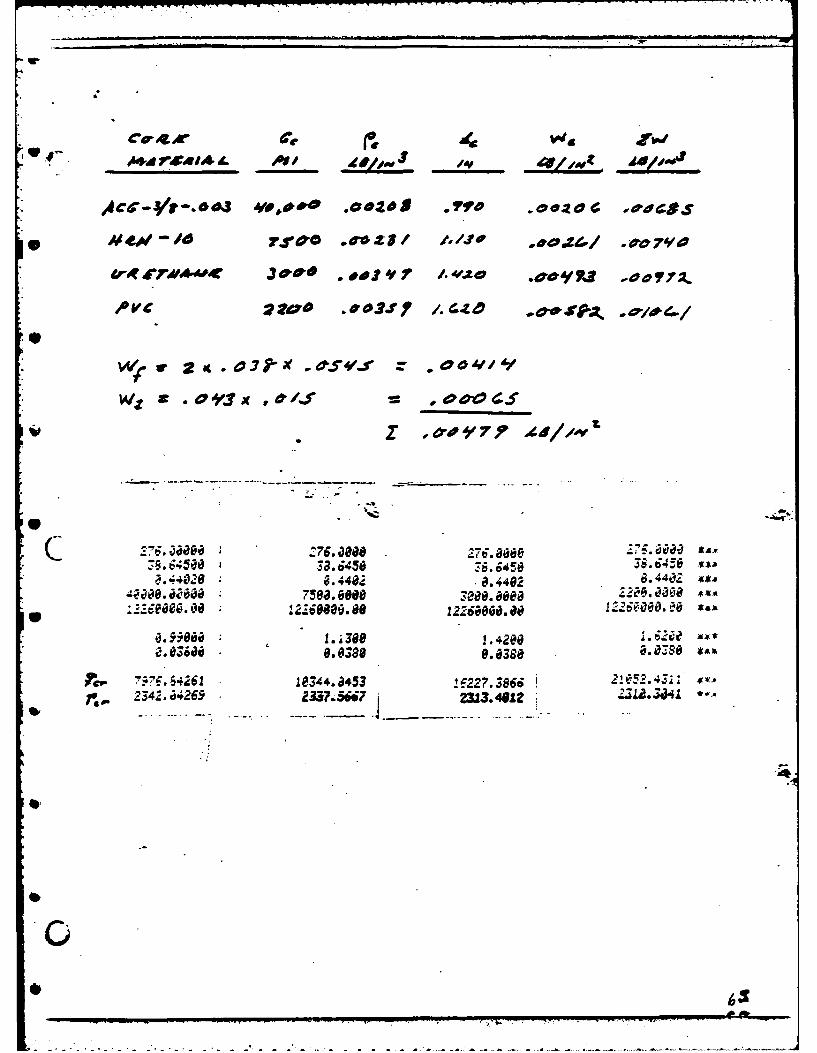
PVEC- Z'i ZOO .03SP1 *
. ' #Ail -',1? A s
Iv MOOO . 3 088 7,0.88 . 5 Co . ., .45 a,.11 2
.7.
3090".0 309"s BOO M8.8' " 700 000 '.io " -- rfe
. _ . -060...
2 80. 150. "0.0900. 9e00• . ,4540, . 6,45849 38. 6450 'e 4 8,645C
' 1.41 e I r,: 75 06:0 0 }. 424 . 249 ." "4
"38198#8, eee 39Zi# 0o#eeo 3019000. 000
.30.1.400' 159 . ... aoeeae. 9" 0.0900 0. 0908
7526..1495 981.91. 170 .6968 I 85. 6193,
. .,... Z._. - 8,
4 P V*. 6'r wr -r . /~
II
*:rx
)fc 76va388j17 *4.,
MAO&~ ~ ~ ~ ~ ~~~I 4eo 7WeAMrdY,* rAitl, M
a0s
Pro AtS.Iv .0404 ,' JOS7 WS #s
9w
?4*6J/ OPJr JS42AL dp04/
*J . g gj4 *
ly~ otc AVA

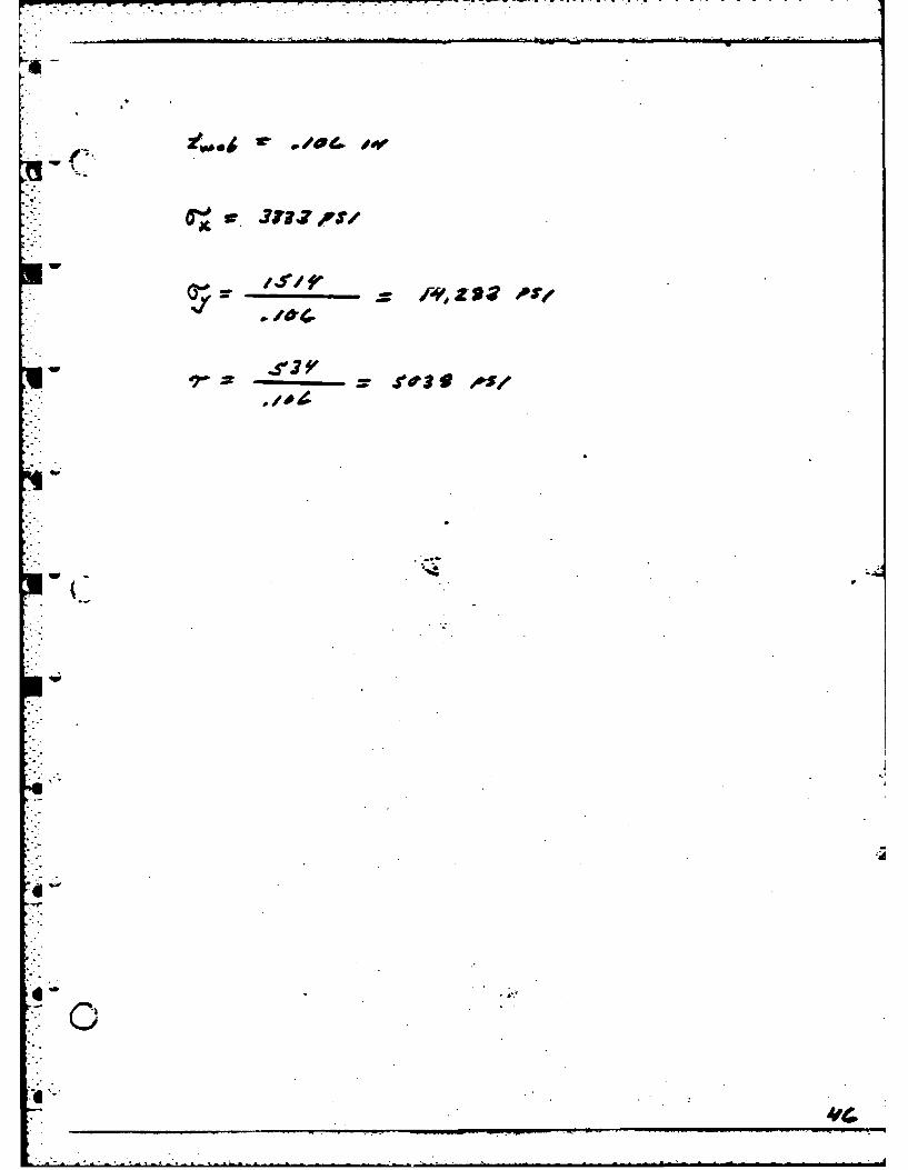
I-33T3 i"
z .4 AU -7J37 E~
VI
-ai
r= 3/ ,?rpi 7*7
. ......
7~t j~ .~#.v~$tuC4fS/auk"~
* Cejer-
Aree ,V
700~
_______~3 ,4 15, )op( 3lv/ oO
JP CO AOV.. ~ .
SfciF '
4.s4# z .90 4
'r 37uals/
qw
-. 444
11Ao - -4 - -
Y09PO -&aJVY 04~~ c~*g /*74 011f.Z l
Ave ~ .,o.*,44-rpJ~,G/t
* . i._ cas-e
775.6456 38.6450 4E,45 345t *v#.4 3 6 .4289 6.4289 0.42B$
0.093516e. a#& 3.516000.099 3!iiaeo.eaf ;;
' d 1~n8a 1.690 1.95092.50~538 89536 90539 .0538 *
ma 91 .9017.S484 12097.9?183 16-7. 6#rf23A. 245 2MI..!17J 231.540.4020 s
W 7401r M
.p
p 4#40# /A*
wA
4 S
27i.. 6~ a 0a/ 7.
3.6450 /.v/D 38.Sa.429 it6.Q.
086 200~ w690 e 3sis.9 P7 356As
1.1 r(.5 1.1
76483-4
Z3165232;3.819
Il-l. . . , -- - - .__ . . . ... ..-
Mod -rt gx
AJ s arr',dr~US/
"',.'t .D - 4 f' o*po
4-60 /JC JT A 4J
.f. Of1/ .o S, "7f .O.OV
PI
it. *T,,f a&,*• A'o- . re
-- * V .*
a *loto
"W
*~.,V7 4# *4#
coO~r 7W0AIO~r #,~OJq AW P -rVV
a rc c ri
c#lI7p~i~rM'ff PP AI4P ~ P
OL
- - - - - - - - -
76.0002 6.00Me 276.80 276.08628.38 .8.i458 38.6450 38.6458 Wig*
;.248 0. 4246! . 6.4248 I0.4248 *- 5136. Joe# MO.8800 4800000O
7 fWC. 900 84760.0 8471803. 800 8471083.8ae
2.'0008.58 1.64,31 i.4100 *-
1.0279 0.627a 0.0278 0.0270 '
At
W*V~~jn ArAeope Mmd w4 jlrao o~
2wW~ .CJdO r * 0 f-
0" : o g4dyfo 'ox
4A4
.DC/
ws
LIP,
.WA r . +-"s
W4
48M. " . OJ"P -iv.
84700.00 e47886 0" 847189. 0"/ 94,780.000
A*- 7.o a 'O,.ef .L*. /.jU'a .oo J.., ."oo 7
0.070-9o 0$ . .aS. 8..0 0.03,09,s ,a
(: a'*4J)7d'4 4 DDo .o=iI /, T$# .oe. Op
PVC" tz,,0- .' 90.47 1.1*D31D? ./oS/
S1.
-. 4 .. 4.. .O .-4 .428 ,,
274.680. BO 7;'6.e BO . 24760800 84 6.608 B *O*r
3 I.6458 3.458 * . OI.;O
7725.0599 9 302.4739 13197.313! 162,-7.1019 -.- 341.1768L 2328.4928 -- 677 231.7221 *.
70 /,. *
ors 9J, 7 gg - Z
*~~~0 '#J7 0~S CSa 0
7;Cz Y't 7~.4 ,T2
*~~~ 44S*,~fA dM.V 9
V (7 7'Y S *.V~in4afpi
f z~% ~'-p$
33$? jb-f
ArIhlP
VieJ~
Air
./Oy sod *oor.t
z 4-
.4'4* 9
aw co
Z .3 0 40 y tovA
94 0~=' I?~~#'ps's
4
"-6 *2I ,We'4A$ vCd~ '~ d r
4r 3D.:.'I
-,A4 . A df/OW
*r 40=
• .o€r
Wi f** OW__ _____ASw 4 j e/
* ~ ~ ~ ~ ~ ~ 0 -. AI#'0 jt 2rr
2i7 000 6.06,96
,PVC *?'-.'. .ooo .aooto .4 *eo.so .OIJJ,),
8 60 8 .,O$aD9 38.. 645 3.. 64158
W O .= o 0..o$ ., a . a 38 a
•. - .. . .--
*276. 000 276.880 267. 0800 Z76 .08 ,.*ees
38.6 58 38.6 450e 38. 6450 36. 6450v9.8.1e8 6. $010 9. 380 0 .30
49M6.9890 7509.6800 U068.8889 2200.990812208.8"9 8122900.88 8122008.80M 8122080.800
*.9see 1.128 1.439a 1.i3N7 0 0570 8.085708.6579 8.8570!
-79?.3405 918987.6142324J"7 231.96 2344.2379 23 75Z( -'
Ar' A7JACS
C .:t~9* ,~ig~t4 ,~-2-hAJ
7c 902Oj 1.~ Solr 0= q~eZ.S p/ 9.f.~ v
-. ~ 769 ,rZ ,
/Si 400TJ? ,edP
Sob
, " IB -2 - f/
ee.
bD6Y
• (o.W 77, 1*%
tj4'
.iVt )$I6/ 71W Y 47J 4*
a rg r vjo
i - 24
2.* Al J' ^
* (y* .41*ZDVy) (4.0[-7)
4a f2
6/fxzo Ag7, a
ArJ /. e.
di0.5cy*.G*d'g,
SO
co
'MW
C4e~rM ~
ACC-31/,dA3 V0,00'a .*I, -Fro .40400 4 woooco
0V Ad DDJ /.6.o ~./C
40A
= .Oj'3c ,O/6 ovoel_
0.440. 4a . 44022 *.
75199 2 8.8#1a 0 .i
1.391.42800.60e *a 8.0380 0.0380 Cl *A
S ;.64261 103'4.8453 2.' -2!..36661~ 342. j4265 3?.672313.4912
W44r A0044-44- VX44-W C00-ofoW OJ *
$ACC~ hJ - A - -
4c , OwA V/
S O~3fa / t).P/ jz .9 e y a t o~
4 IV/70 AAr I.s 1.4'1o
* ( ~ AS'D P6,0'i
Ao . OdCIZ7 ..o0'7O poS~t~*SG ~.
w e
* WJ'd AotDUU* 4'04 AOXA-40 rwopA~A*cv
W4~~~e s'*4 ro ret t
AA4e £'O -i~ St- . sdJtAAj zI -
&/*
* love
1"~Iw PtAP A,4 "0J jf~
Acs.d0'V -0~r
CfC,4 'A4 A .dAA AZP749 l r* C4 Of rWOAL CdA*Z* e.
*44AC Ar 14,,70 ol
(--t.
'-4'
,4#N' 0,0r Aff T~C //4 *',f
laJ4
I. I -
Sw~j~Il ~'~'~ .zsP~ L
-er, A .j
A4~AeA o .~eCC. Ci.4r40,
I A
I I.
IL
I-t
Za
I.0
*1-
I t I
fil
fil
I i
JA"II6 1i0 +1 ii~
* 7.EAd. WdE d4j94-
eI-n, " . is. '
I i.
o toto A MAO##* 44P I". #'1 l #J . -.- €.
Z r.2r j P.- T74 t7077 a 'i /t-
-
.4 asg
o DDSe 042©/i ---~'/.?
i.t
a! PS€ =" ,.it /777 i,7i ~
* Tw ...7'? A
• ,_-i=i"!, irld 0ef p , .SC-
O-AI28 6±6 BRIDGE WOUND WEB MODULEiU) EDO CORP SALT LAKE CITY UT 2/2FIBER SCIENCE DIV 1983
UNCLASSIFIED F/G 03/13IIIIIIIIIhIIIIIIIIII|IIIIIMESA
m
%- -7* -
'. .4
I2.
1111 11j3.02la 12.2
WO 12.0
•. EE.
1151
,... lu- ,=..... ,
MICROCOPY RESOLUTION TEST CHART
NATIONAL BUREAU OF STANDARDS-]9e3-A
I
'- " " -. . . .'- " . -' . ' . -" ' " - " - . " ' , . i l " . - - . *- -" " " " i . . . -
* 7*~ AArdW,*-A4C. * ACbO
..0. r .v~&,* %frrr A- A- A~r 7w 4elho
0.79 it
00,4~~~~/*. A0Al7/, WdV$
£1 SOA' '% ~ .Y
dm A
V~tIVA 4
Irs
POI pot f9 3/
(4 Ole 9?-i'
now-
M// 11/
Ai/OCA WS PA14 r
16 AC'0 A#~AAefW,,
4 ce dc~vs
22
Arm T E~r'A
CI, ($r J
4A C4CAA 24r
* dr ft
Kwe
A ___
.. . . . . . . .
Ca
*A /w me~ ,'
4KO,# 0'00 OorO ACO'
*Er' es.i *DEj' orSA4
E .N7ZP-4
*63e 3F .7!*
S572eo. Nei44- 83729.89 ** 937:21eaacl
S4e9000e eNeOoe 4000e.U8 Oz 8M 88*w 6.2588 AA 6.259 ~e.1eoo
P/lw 18329.5i44 m.S, -*17.43
M.298 a.< .79032a ..
e~seoo 9.U50
38.3789 wu( 78.3799.0 .
8372e9:9e9: . 25.809 .
83-200000 o37.s.oee *
6.79ff 6.25ff0 . i6.95mo~e 6.95ff**
* s1754.5.27, ' .Z: 337.2719 $XS
Wv#vIelg ^20D.A4 #*f4 1A a-, eA Al. #M,
I.Lo o
- -- '-t - -~ -
. .. .. * . -
- -.. ~- .- .
'-I"'-
0*. . - J s~u
I m . I
I'4'
IImm m, -. in-in . . - - - I
.mmmm m m.minm mmmm~f~uumm1z.m......m...w, K0 ~
~
I
* 1
4 ~1
* I k --
N qhL
*i~4
* a
I
4
eq
I','I'
*1~~mum. mm. mm .mE m
0
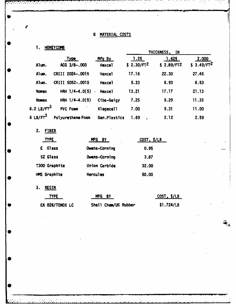
G MATERIAL COSTS
1. HONEYCOMB
THICKNESS, IN
Type Mfg By 1.25 1.625 2.000Alum. ACG 3/8-.003 Hexcel $ 2.30/FT2 $ 2.89/FT2 $ 3.49/FT2
Alum. CR111 2024-.0015 Hexcel 17.16 .22.30 27.45
Alum. CRII 5052-.0015 Hexcel 5.33 6.93 8.53
Nomex HRH 1/4-4.0(5) Hexcel 13.21 17.17 21.13
Nomex HRH 1/4-4.0(5) Ciba-Geigy 7.25 9.29 11.33
6.2 LB/FT3 PVC Foam Klegecell 7.00 9.31 11.00
6 LB/FT3 Polyurethane Foam Gen.Plastics 1.69 . 2.12 2.59
2. FIBER
TYPE -MFG BY COST, S/LB
E Glass Owens-Corning 0.95
S2 Glass Owens-Corning 3.87
T300 Graphite Union Carbide 32.00
HMS Graphite Hercules 50.00
3. RESIN
TYPE MFG BY COST, $/LB
* EA 826/TONOX LC Shell Chem/US Rubber $1.724/LB
0
ADDENDUM II
0
0
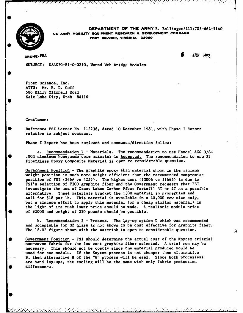
DEPARTMENT OF THE ARMY B. Ballinger/l1/703-664-5140US ARMY MOBILITY EQUIPMENT RESEARCH & DEVELOPMENT COMMANO
FORT SELVOIR, VIRGINIA 22060
DRODME- PEAS ;
SUBJECT: DAAK70-81-C-0210, Wound Web Bridge Modules
Fiber Science, Inc.ATTN: Mr. H. D. Goff506 Billy Mitchell RoadSalt Lake City, Utah 84116
Gentlemen:
* Reference FSI Letter No. 112236, dated 10 December 1981, with Phase I Reportrelative to subject contract.
Phase I Report has been reviewed and comments/direction follow:
a. Recommendation 1 - Materials. The recommendation to use Hexcel ACG 3/8-* .003 aluminum honeycomb core material is Accepted. The recommendation to use S2
Fiberglass Epoxy Composite Material is open to considerable question.
Government Position - The graphite epoxy skin material shown in the minimumweight position is much more weight efficient than the recommended compromiseposition of FSI (246# vs 425#). The higher cost ($3006 vs $1665) is due to
* FSI's selection of T300 graphite fiber and the Government requests that FSIinvestigate the use of Great Lakes Carbon Fiber Fortafil 3T or 4T as a possiblealternative. These materials bracket the T300 material in properties andsell for $18 per lb. This material is available in a 40,000 tow size only,but a sincere effort to apply this material (or a cheap similar material) inthe light of its much lower price should be made. A realistic module price
* of $2000 and weight of 250 pounds should be possible.
b. Recommendation 2 - Process. The lay-up option D which was recommendedand acceptable for S2 glass is not shown to be cost effective for graphite fiber.The 18.02 figure shown with the asterisk is open to considerable question.
* Government Position - FSI should determine the actual cost of the Knytex triaxialnon-woven fabric for the low cost graphite fiber selected. A trial run may benecesary. This should not be costly since the material produced would beused for one module. If the Knytex process is not cheaper than alternativeB, then alternative B of the 'V" process will be used. Since both processessare hand lay-ups, the tooling will be the same with only fabric production
• differencos.
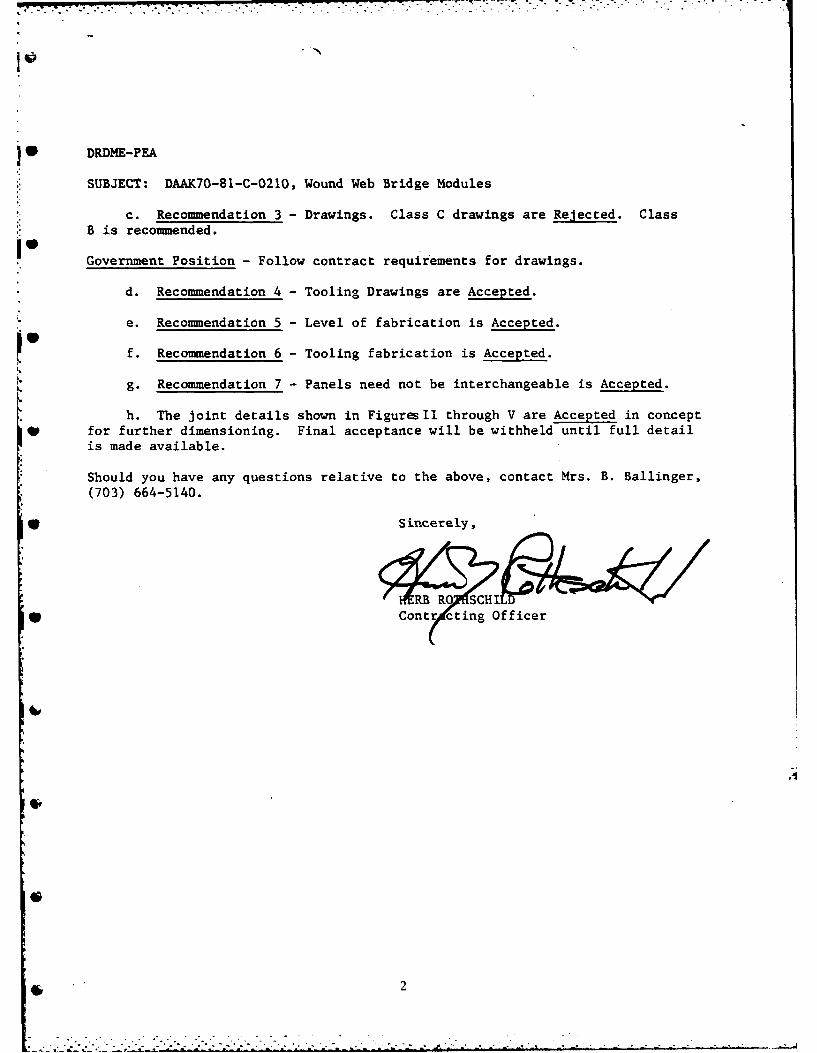
DRDME-PEA
SUBJECT: DAAK70-81-C-0210, Wound Web Bridge Modules
c. Recommendation 3 - Drawings. Class C drawings are Rejected. ClassB is recommended.
Government Position - Follow contract requirements for drawings.
d. Recommendation 4 - Tooling Drawings are Accepted.
e. Recommendation 5 - Level of fabrication is Accepted.
f. Recommendation 6 - Tooling fabrication is Accepted.
g. Recommendation 7 - Panels need not be interchangeable is Accepted.
h. The joint details shown in Figures l through V are Accepted in conceptfor further dimensioning. Final acceptance will be withheld until full detailis made available.
Should you have any questions relative to the above, contact Mrs. B. Ballinger,
(703) 664-5140.
* Sincerely,
Con r ctn fficer
* 2
I.
I.
I. ADDENDUM 111
I.S
S
ZownE LTR DESCRIPTION IDATE APPO
TITLBRDEWUDWBMDL
-IM - FIE -
"The views, opinions, and/or findings containedin the report are those of the author(s) andshould not be construed as an official Depart-ment of the Army position, policy or decision,
* unless so designated by other documentation."
0o
1. INTRODUCTION
The Wound Bridge Web contract is an effort to reduce the weight of theexisting bridge. The wound bridge web contract, which provides forthe determnation of contract feasibility, design, fabrication, testand assemb~ly of two bridge web modules, was received at Fiber Science onSeptember 28, 1981.
Phase II of the contract, entitled "ENGINEERING DESIGN AND DOCUMENTATION",includes (1) manufacture and test of samples to verify properties used
l in the design, (2) production drawings and specification, and (3) detaileddescription of production methods including quality assurance provisions.
This is the final report under Phase II of the contract.
V
U
.
S
MO
II. AIMS AND OBJECTIVES OF PHASE II
1. Perform physical testing of the bridge web design materials toverify design allowables.
2. Re-evaluate safety margin of bridge web design based upon test
results.
3. Develop Engineering drawings of bridge web components.
4. Detailed description of production methods.
* 5. Order materials for Phase III.
6. Design tooling for Phase III.
0w
4.
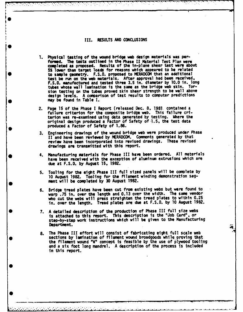
III. RESULTS AND CONCLUSIONS
1. Physical testing of the wound bridge web design materials was per-formed. The tests outlined in the Phase II Material Test Plan werecompleted as proposed. Results of the in-plane shear test were about5S lower than target loads for reasons which appeared to be related
• to sample geometry. F.S.C. proposed to MERADCOI4 that an additionaltest be run on the web materials. After approval had been received,F.S.O. manufactured and tested three 3.5 in. diameter by 10.0 in. longtubes whose wall lamination is the same as the bridge web skin. Tor-sion testing on the tubes proved skin shear strength to be well abovedesign levels. A comparison of test results to computer predictions
* may be found in Table 1.
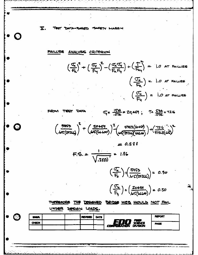
2. Page 15 of the Phase I Report (released Dec. 8, 1981. contained afailure criterion for the composite bridge web. This failure cri-terion was re-examined using data generated by testing. Where theoriginal design produced a Factor of Safety of -1.5, the test dataproduced a Factor of Safety of 1.86.
3. Engineering drawings of the wound bridge web were produced under Phase11 and have been reviewed by MERADCOM. Comments generated by thatreview have been incorporated into revised drawings. These reviseddrawings are transmitted with this report.
* 4. Manufacturing materials for Phase III have been ordered. All materialshave been received with the exception of aluminum extrusions which aredue at F.S.D. by August 15, 1982.
5. Tooling for the eight Phase Ill full sized panels will be complete by10 August 1982. Tooling for the filament winding demonstration seg-ment will be completed by 30 August 1982.
6. Bridge tread plates have been cut from existing webs but were found towarp .75 in. over the length and 0.13 over the width. The same vendorwho cut the webs will press straighten the tread plates to within 0.25in. over the length. Tread plates are due at F.S.D. by 10 August 1982.
* 7. A detailed description of the production of Phase III full size websis attached to this report. This description is the "Job Card", orstep-by-step work instructions which will be given to the ManufacturingDepartment.
8. The Phase III effort will consist of fabricating eight full scale web* sections by lamination of filament wound broadgoods while proving that
the filament wound "W" concept is feasible by the use of plywood toolingand a six foot long mandrel. A description of the process is includedin this report.
0
0
lim
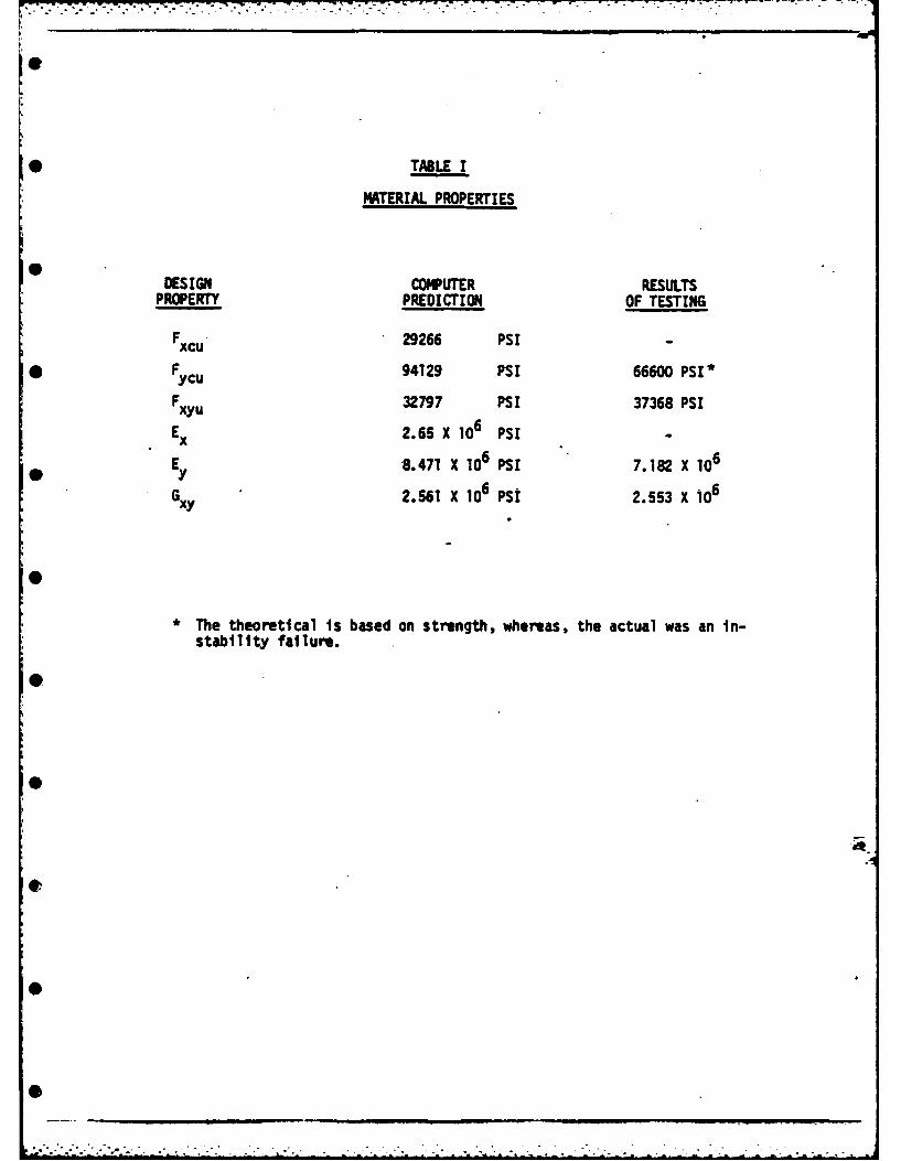
* TABLE I
MATERIAL PROPERTIES
DESIGN COMPUTER RESULTSPROPERTY PREDICTION OF TESTING
FC 29266 PSI
*F yu94129 PSI 66600 PSI*
FXU32797 PSI 37368 PSI
Ex2.65 X 10 PSI
E y8.471 X 16PSI 7.182 X 10⁶
G XY2.561 X 106 PSI 2.553 X 10⁶
*The theoretical is based on strength, whereas, the actual was an in-stability failure.
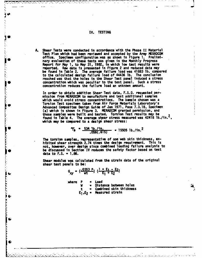
IV. TESTING
I
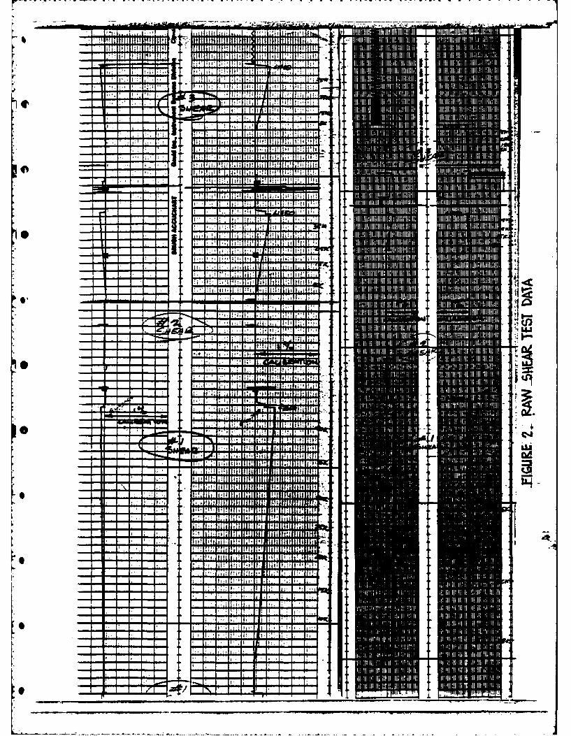
A. Shear Tests were conducted in accordance with the Phase 1I MaterialTest Plan which had been reviewed and accepted by the Army MERADCOMoffice. Specimen configuration-was as shown in Figure 1. Prelimi-I. nary evaluation of these tests was given in the Monthly ProgressReport for May 1, to May 31, 1982, in which low test results werereported. Raw data is presented in Figure 2 and reduced data maybe found in Table 2. The average failure load was 41883 lb. comparedto the calculated design failure load of 44436 lb. The conclusionreached was that the holes in the Shear Test panel induced a stress
1 concentration which was peculiar to the test panel. Such a stressconcentration reduces the failure load an unknown amount.
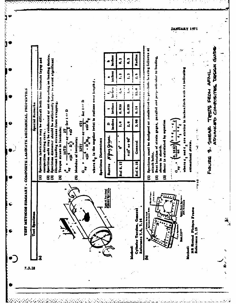
In order to obtain addition Shear Test data, F.S.D. requested per-mission from MERADCOM to manufacture and test additional sampleswhich would avoid stress concentrations. The sample chosen was aTorsion Test specimen taken from Air Force Materials Laboratory'sAdvanced Composites Design Guide of Jan 1971, Paqe 7.3.18. Specimen(a) which is shown in Figure 3. MERADCOM granted permission, andthese samples were built and tested. Torsion Test results may befound in Table 4. The average skear stress measured was 42418 lb./in.,z
which may be compared to a design shear stress:• 3 15505 lb./in.2
The torsion samples, representative of one web skin thickness, ex-hibited shear strength 2.74 times the design requirement. This isnot, however, over design since combined loading failure analysis to
0 be discussed In Section IV reduces the safety factor based on testdata to F.S. - 1.86.
Shear modulus was calculated from the strain data of the originalshear test panels to be:
Gp 035 PL i (1 +Ei -E2
.where P w LoadW - Distance between holest a Combined skin thicknessE1,E2 a Measured strain
. . . . . . .

Va -24 aOLT ON 2" CENTERS PLCE
4. 1. 40LP- 'T4U 4
4 PLACM .
* GRANITE e PK'X 4
+ ALUM WJ/C SAMOW104~9D) 7.0r -sr
44-
0+
0+ +. +a + + +R
soK A
LODN
IPI
-i~ I;:;~; I j:11:
U_' I
0' OA4
i ! IA
Il : 1 :
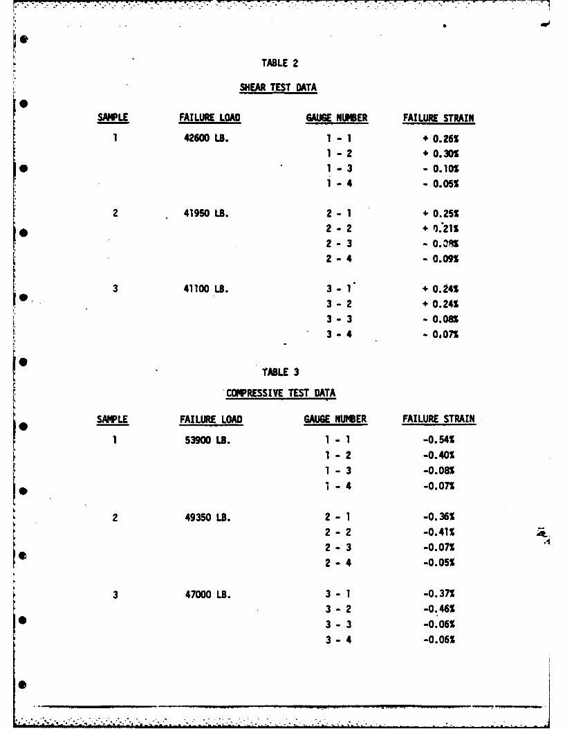
TABLE 2
SHEAR TEST DATA
SAMPLE FAILURE LOAD GAUGE NUMBER FAILURE STRAIN
1 42600 LB. 1 -1 + 0.26%1 - 2 + 0.30%
S1- 3 - 0.10%
1 - 4 -0.05%
2 41950 LB. 2 -1 + 0.25%
2 2 + 1.21%
2- 3 - 0. 0 R2-4 -0.09
3 41100 LB. 3- 1 + 0.24%
3 -2 + 0.24%
3- 3 - 0.08%
3 -4 - 0,07
TABLE 3
COMPRESSIVE TEST DATA
SAMPLE FAILURE LOAD GAUGE NUMBER FAILURE STRAIN
1 53900 LB. 1 - 1 -0.54%
1 - 2 -0.40%
1 - 3 -0.08%
•-4 -0.07%
2 49350 LB. 2 - 1 -0.36%
2 - 2 -0.41%
2 - 3 -0.07%
2 - 4 -0.05%
3 47000 LB. 3 - 1 -0.37%
3 - 2 -0.46%
S3- 3 -0.06%
3 - 4 -0.06%
0i
. ,- .. .- ". --. -
b ,
e
ifi'S l a v
low ka .4 A
am a a - - -
2 ._ 0 •
E-" .: ,- ; a - ; : .-
' I i- =, ' j2* .' , -=
I .; .. ,_ * I " @°I Ia I
I IVr, : " . . n . . n - . , -l .
-%- o; --
-30 U .S , - , .Ui ! 1 i o, -U' ' _6.I I Wa _.g - m. Im _,!. ._, , .,,. . 0. . o.. _ .
-" "- " * V"AdI i "" -1 N- lol- .'
" ]Ill - _ U
'S S• .. f ;-i.
7'.s0- 0"-
. -. * j. .. .. .. .I A
..-- .0 I~ .. . " . . . -. ,W.
-Of,*,
* - ~ x
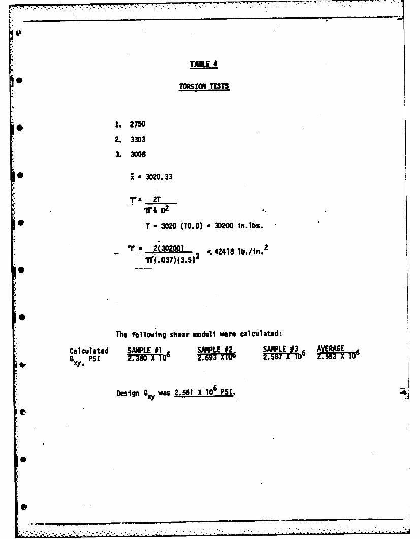
TABLE 4
TORSION TESTS
1. 2750
2. 3303
3. 3008
* ; ,,3020.33
'- 2T
ir+ 2
0 T - 3020 (10.0) - 30200 tn.lbs.
S2(30200) lb.
Tr(.037)(3.5)2
The following shear moduli were calculated:
Calculated SAMPLE #1 SAMPLE #2, SAMPLE 13 6 AVERAGEG XY' PSI 2.380 X 10r2T!TMU 237 6 2.53iD0
Design Gxy was 2.561 X 10⁶ PSI.
t
• ~~~..-.-.. .. .. .. ....-........ ....... •:-.. . ".-..... .-..• -. ,_".",,"-".- ," ,"".",' ," ,.:,
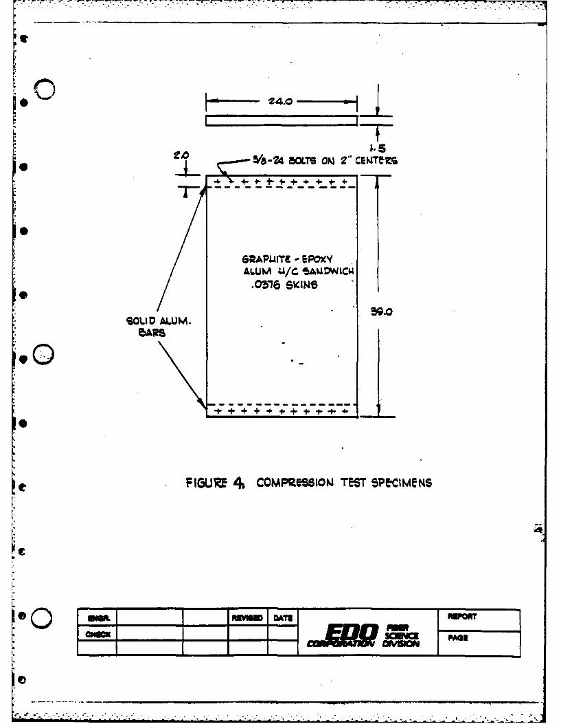
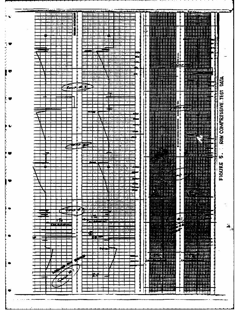
B B. Compression Tests were conducted as outlined by the Phase II MaterialTest Plan. Specimen configuration is shown in Figure 4. Raw testdata may be found in Figure 5, and reduced data appears in Table 1.
While the test results exceeded design requiresmnts, they were lowerthan computer predictions because they failed in a different mode thananticipated.
Test data recorded on the narrow chart is unaccountably low, about 1/5the expected level of strain. It is suspected that a calibration er-ror occurred.
0
®4
r1t
10.A/6-24 BOLTS ON 2"CIZ
+C + +
GRAPUITE - EPOXY'ALUM 44/C 'SAUDWLCIA
.O3,76 SKINS
SOLID AL.UM.5ARS
90
F-IG(URE 4COMPRESSION T%7T SPE-CIMeNS
1 jm ATI Er
pm~
ONONDEE
p. i: .- -.
4i 4-
- - -3F
5'
FAILVIM ANiALYSIS CRTeM
1.0 A ~w
* (......)~.. .0 'Ar FAILUZG5
FeCM~~ ~ ~ ~ Laro 1:'A-Ir 7
0 _ _.
--
r- 0.5
T~~mpMim 'r4-4 We we oLb. Nor aL
Ome amRW DT AORT
CHECKSCEY PAG
VI. FILAMENT WINDING PROCESS DEMONSTRATIONlg
1. Tooling
The mandrel will be made from 1/2 inch plywood with piano type hinges,about six feet long, with full width webs.
2. Demonstration winding will be with graphite fiber, epoxy resin andaluminum honeycomb. Winding sequence will be as follows:
a. Winif inner skin (900, ! 450)
* b. Apply 120 glass cloth
c. Apply honeycombd. Apply 120 glass cloth
e. Wind outer skin (t 450, 900)
Sf. "SO stage to formable, tacky resin consistency
g. Cut skin and fold mandrel into "k" configuration
h. Secure into proper position
i. Cure
0
44
4,f
im I
4A4
4114
.4 or
RA,'