ICU TRACKLESS SLIDING DOOR -...
16
ICU TRACKLESS SLIDING DOOR Subject to change without notice DORMA AUTOMATICS, Inc. 1 924 Sherwood Drive Toll-Free: 877-367-6211 Lake Bluff, IL 60044 Fax: 877-423-7999 E-mail:[email protected] Rev. 1/05 Installation Instructions 0 Interior View
-
Upload
truonghuong -
Category
Documents
-
view
217 -
download
1
Transcript of ICU TRACKLESS SLIDING DOOR -...

ICU TRACKLESS SLIDING DOOR
Subject to change without noticeDORMA AUTOMATICS, Inc. 1
924 Sherwood Drive Toll-Free: 877-367-6211Lake Bluff, IL 60044 Fax: 877-423-7999E-mail:[email protected] Rev. 1/05
Installation Instructions
0
Interior View

ICU TRACKLESS SLIDING DOOR
Tools Required:
Suggested Fasteners Required - (Not supplied)
ScrewdriversSmall Straight (Flat Blade) - for Terminal Block wiring#2 Phillips (Crosspoint) - for various #8, #10, and #14 screws
Wrenches / Sockets15/16" wrench - for carrier and anti-rise roller adjustment
Allen Wrenches1/8” - for “SO” arm stop & “SX” bottom pivot5/32” - for “SO” top pivot5mm (3/16”) - for “SO” arm pivot screw5/16" - for carrier and anti-rise roller adjustment
Electric Drill with the following drill bits -5/32" (or #22) - for installing #10 sheet metal screws into adjacent storefront13/64" (or #7) - for installing #14 sheet metal screws into adjacent storefront1/4" - for clearance holes in jambs82 degree Countersink
Impact Drill with the following masonry bits -1/4" - for #10 screw anchors5/16" - for #14 screw anchors
Level - suggested 4' minimumStep Ladder - 4' or 6'Tape MeasureCaulking and Application GunElectrical Wire Strippers /Cutters - for monitor wiringGrease [to hold “SX” bottom guide block on shaft]
Jamb Attachment Screws -#14 X 2-1/2" PHSMS (Pocket Jambs)#14 X 3" FHSMS (Tube Jambs)Optional Anchors for masonry
Basement Bearing Plate Attachment Screws#10 X 1-1/2" FHSMSOptional Anchors for masonry
Header Attachment Screws#14 X 1-1/2" HHSMS#14 Flat Washer
Construction Shims - for squaring door frame in opening
Subject to change without noticeDORMA AUTOMATICS, Inc. 2
924 Sherwood Drive Toll-Free: 877-367-6211Lake Bluff, IL 60044 Fax: 877-423-7999E-mail:[email protected] Rev. 1/05

ICU TRACKLESS SLIDING DOOR
Components (2 Leaf) - Overview
1
Subject to change without noticeDORMA AUTOMATICS, Inc. 3
924 Sherwood Drive Toll-Free: 877-367-6211Lake Bluff, IL 60044 Fax: 877-423-7999E-mail:[email protected] Rev. 1/05
1 Header2 Header Closeout Cover3 Jamb Tube4 Cover Extrusion
5 Sidelight6 Sliding Panel7 Positive Latch Pull8 Flush Bolts
9 Base Bearing Plate10 Floor Guide
1143
11
2
4 3
1
6
6
77
9
9
5
5
10
10
8
11 Bearing Pivot

ICU TRACKLESS SLIDING DOOR
Components (4 Leaf) - Overview
2
Subject to change without noticeDORMA AUTOMATICS, Inc. 4
924 Sherwood Drive Toll-Free: 877-367-6211Lake Bluff, IL 60044 Fax: 877-423-7999E-mail:[email protected] Rev. 1/05
1 Header2 Header Closeout Cover3 Outer Roller Track4 Jamb Tube
5 Sidelight6 “SX2” Sliding Panel7 “SX1” Sliding Panel8 Positive Latch Pull
9 Flush Bolts1011
Base Bearing PlateFloor Guide
4
5
41
5
7
7
10
10
88
12
12
6 6
12 Bearing Pivot
3
2
11
11
9

ICU TRACKLESS SLIDING DOOR
Header to Jamb AssemblyFasten the header unit to the jambs using (4) #10 x 1” phillips pan heads (2 per side). #2 Phillips screw driver required.
3
Subject to change without noticeDORMA AUTOMATICS, Inc. 5
924 Sherwood Drive Toll-Free: 877-367-6211Lake Bluff, IL 60044 Fax: 877-423-7999E-mail:[email protected] Rev. 1/05

ICU TRACKLESS SLIDING DOOR
1
2
3
22
The mounting of the unit to the rough opening must meetapplicable building codes and standards.
4
Assembly1 Place the header & jamb assembly into the rough opening.
2 Level all sides and shim as required.
3 Fasten assembly into rough opening, after verifying unit is level and plumb in all directions.
Find highest floor elevation and shim accordingly.
Subject to change without noticeDORMA AUTOMATICS, Inc. 6
924 Sherwood Drive Toll-Free: 877-367-6211Lake Bluff, IL 60044 Fax: 877-423-7999E-mail:[email protected] Rev. 1/05
4 Place Base Bearing Plate in position.
ICU TRACKLESS SLIDING DOOR
approx. 80°
90°
1
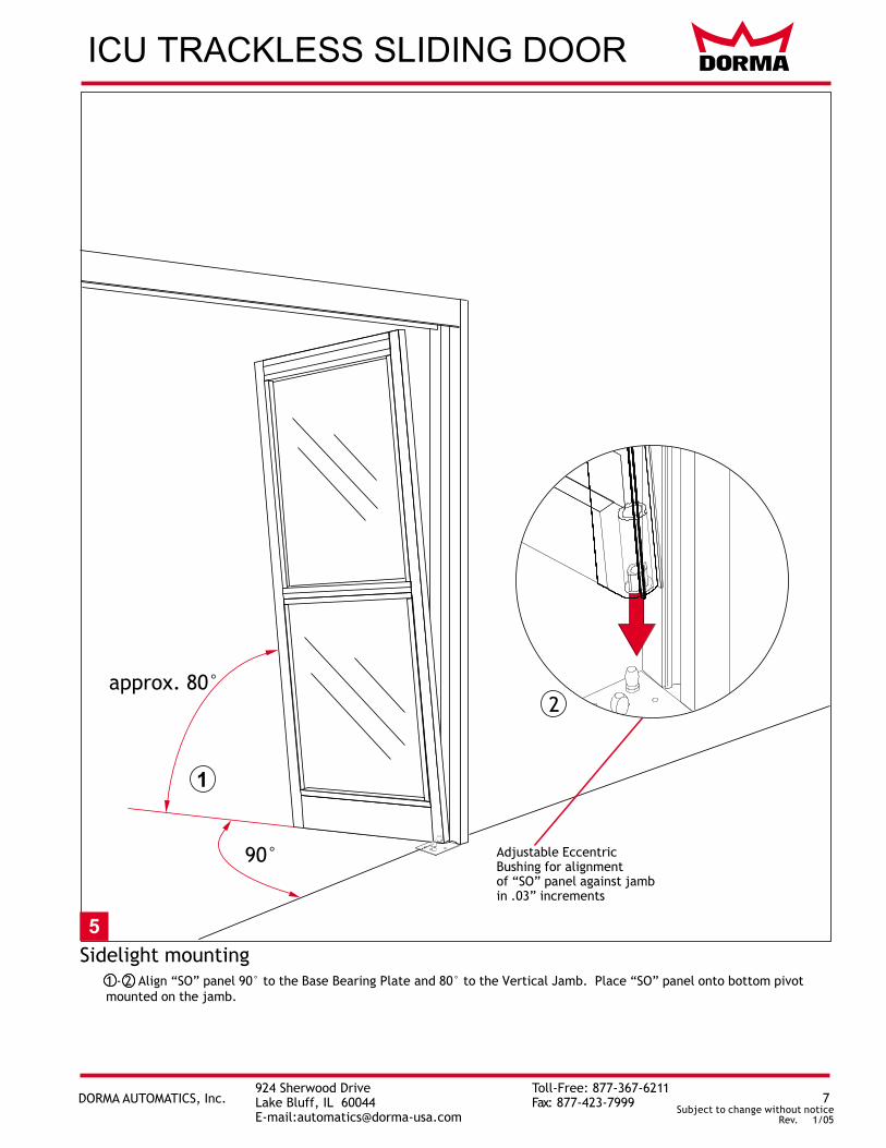
5Sidelight mounting
1 - 2 Align “SO” panel 90° to the Base Bearing Plate and 80° to the Vertical Jamb. Place “SO” panel onto bottom pivotmounted on the jamb.
2
in .03” increments
Adjustable EccentricBushing for alignmentof “SO” panel against jamb
Subject to change without noticeDORMA AUTOMATICS, Inc. 7
924 Sherwood Drive Toll-Free: 877-367-6211Lake Bluff, IL 60044 Fax: 877-423-7999E-mail:[email protected] Rev. 1/05

ICU TRACKLESS SLIDING DOOR
6
3
1
Securing the Sidelight2 Push “SO” Panel vertically to align with jamb. Rotate upper “SO” arm and lightly fasten to screw plate located in header.3 Align and plumb “SO” Panel.4 Tighten (3) 1/4-20 x 5/8 fasteners in “SO” top pivot, securing “SO” Panel to header using 5/32” allen wrench.
6 Loosen fastener. Close “SO” panel and align “SO” magnet/latch sub-assembly. Tighten fastener using ½”socket/wrench. For roller catch tension adjustment, see page 14.
24
5
5/16-18 x ½”
Subject to change without noticeDORMA AUTOMATICS, Inc. 8
924 Sherwood Drive Toll-Free: 877-367-6211Lake Bluff, IL 60044 Fax: 877-423-7999E-mail:[email protected] Rev. 1/05
5 Loosen 1/4-20 x 5/8 socket head screw. Adjust locking plate with flush bolt to align with anchoring hole in header.After tightening screw, close sidelite and test flush bolt for proper operation. (1/8”Allen required)
6
5
5
Flush BoltAdjustment Screw
1 -
Locking Plate
Flush Bolt
Locking Plate
1/4-20 x 5/8”screw

ICU TRACKLESS SLIDING DOOR
7Hanging the “SX” or “SX2” panel
12 Place “SX” or “SX2” panel rollers onto outer roller track by lifting panel in place.
Lift ”SX” or “SX2” panel over Bottom guide assembly located on bottom of “SO” panel.
Subject to change without noticeDORMA AUTOMATICS, Inc. 9
924 Sherwood Drive Toll-Free: 877-367-6211Lake Bluff, IL 60044 Fax: 877-423-7999E-mail:[email protected] Rev. 1/05
When installing a telescopic unit, you must adjust door height completely before proceding to next step
3
3 Adjust “SX” panel per page 11.
1
2

ICU TRACKLESS SLIDING DOOR
(1/8” Allen required).
2
1 Install outer roller track by fastening into masonary opening.
Hanging the “SX1” panel for telescopic 3 leaf and 6 leaf units8
Subject to change without noticeDORMA AUTOMATICS, Inc. 10
924 Sherwood Drive Toll-Free: 877-367-6211Lake Bluff, IL 60044 Fax: 877-423-7999E-mail:[email protected] Rev. 1/05
3 Place “SX1” panel rollers onto outer roller track by lifting “SX1” panel in place.2 Lift “SX1” panel over bottom guide assembly located on bottom of “SX2” panel.
4 Adjust “SX1” panel per page 11.
3
4
2
Outer roller track1

ICU TRACKLESS SLIDING DOOR
AW AW
CW CW
9Vertical Alignment for “SX1” and “SX2” panels
Using the eccentric carrier wheel (CW) and the anti-riser wheel (AW) level the sliding panel. Tighten hex nuts to secure the adjustment.
Adjustment of the anti-riser roller:The anti-riser roller should not contact the top track anywhere along the slide path of the door.
15/16” Wrench
5/16” Allen
Subject to change without noticeDORMA AUTOMATICS, Inc. 11
924 Sherwood Drive Toll-Free: 877-367-6211Lake Bluff, IL 60044 Fax: 877-423-7999E-mail:[email protected] Rev. 1/05
1/64”
3/16”

ICU TRACKLESS SLIDING DOOR
9
Glazing12
Remove the glass stops from exterior side (4 per opening).Center the glass in opening.
3 Properly block and/or cushion glass edges.4 Press the glass stops into place starting with the horizontal stops, then following with the vertical stops.
10
C
B
D
A
1
2
4
LOCKRAIL
PIVOTRAIL
LOCKRAIL
PIVOTRAIL
3
Subject to change without noticeDORMA AUTOMATICS, Inc. 12
924 Sherwood Drive Toll-Free: 877-367-6211Lake Bluff, IL 60044 Fax: 877-423-7999E-mail:[email protected] Rev. 1/05

ICU TRACKLESS SLIDING DOOR
Adjustment of the Breakout-Unit1. Loosen the set screws (a , b & c) to prevent interference while adjusting door. 7/32” Allen wrench required.
2. Use the adjustment screw (d) to lift (CW) or lower (CCW) the leading edge of door.
4. Tighten all set screws (a, b & c) until tight and secure.
Recheck the latched position alignment and readjust as necessary.
3. Continue adjustment until the re-latch profiles are properly aligned.
111
3
Note: It may be necessary to temporarily movedeadstop bracket out of the way to accessadjustment screw “d”.1/8” Allen wrench required.
a b cd
Subject to change without noticeDORMA AUTOMATICS, Inc. 13
924 Sherwood Drive Toll-Free: 877-367-6211Lake Bluff, IL 60044 Fax: 877-423-7999E-mail:[email protected] Rev. 1/05

ICU TRACKLESS SLIDING DOOR
1. Open “SX” & “SO” panels to 90°.
3. Secure stop blocks.
12
Subject to change without noticeDORMA AUTOMATICS, Inc. 14
924 Sherwood Drive Toll-Free: 877-367-6211Lake Bluff, IL 60044 Fax: 877-423-7999E-mail:[email protected] Rev. 1/05
“SO” Panel Breakout Adjustment
2. Move arm stop blocks to engage arm. 1/8” Allen wrench required.
90°
1/4-20 x ½”

ICU TRACKLESS SLIDING DOOR
1. Remove astragral on side of door.
4. Test door for proper Latch operation and Breakout function.
13
Subject to change without noticeDORMA AUTOMATICS, Inc. 15
924 Sherwood Drive Toll-Free: 877-367-6211Lake Bluff, IL 60044 Fax: 877-423-7999E-mail:[email protected] Rev. 1/05
Positive Latch Pull and Latch Pin Adjustment
3. Adjust nut to provide desired Postive Latch Pull Resistance.
PositiveLatch Pull
Adjust Nut HeightTo Change Latch Resistance
3
0.2”
2
Adjust Nut HeightTo Change Pin Engagement
1
2. Adjust nut to provide 0.2” (5mm) of Latch Pin Engagement

ICU TRACKLESS SLIDING DOOR
Subject to change without noticeDORMA AUTOMATICS, Inc. 16
924 Sherwood Drive Toll-Free: 877-367-6211Lake Bluff, IL 60044 Fax: 877-423-7999E-mail:[email protected] Rev. 1/05
Install Closeout Cover
Ensure proper operation of door before installing Closeout Cover. If door is latched shut without proper Positive Latch adjustment, door will not open and Closeout Cover will be difficult to remove.
14
Attach Closeout Cover using 1/4” - 20 screws, one on either end.