ICD Quick Installation - LauterbachICD Quick Installation 6 ©1989-2020 Lauterbach GmbH 2....
56
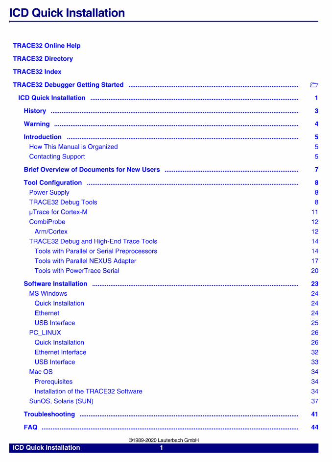
ICD Quick Installation 1 ©1989-2020 Lauterbach GmbH ICD Quick Installation TRACE32 Online Help TRACE32 Directory TRACE32 Index TRACE32 Debugger Getting Started .............................................................................................. ICD Quick Installation ................................................................................................................... 1 History ......................................................................................................................................... 3 Warning ....................................................................................................................................... 4 Introduction ................................................................................................................................ 5 How This Manual is Organized 5 Contacting Support 5 Brief Overview of Documents for New Users .......................................................................... 7 Tool Configuration ..................................................................................................................... 8 Power Supply 8 TRACE32 Debug Tools 8 μTrace for Cortex-M 11 CombiProbe 12 Arm/Cortex 12 TRACE32 Debug and High-End Trace Tools 14 Tools with Parallel or Serial Preprocessors 14 Tools with Parallel NEXUS Adapter 17 Tools with PowerTrace Serial 20 Software Installation .................................................................................................................. 23 MS Windows 24 Quick Installation 24 Ethernet 24 USB Interface 25 PC_LINUX 26 Quick Installation 26 Ethernet Interface 32 USB Interface 33 Mac OS 34 Prerequisites 34 Installation of the TRACE32 Software 34 SunOS, Solaris (SUN) 37 Troubleshooting ......................................................................................................................... 41 FAQ .............................................................................................................................................. 44
Transcript of ICD Quick Installation - LauterbachICD Quick Installation 6 ©1989-2020 Lauterbach GmbH 2....
ICD Quick Installation
TRACE32 Online Help
TRACE32 Directory
TRACE32 Index
TRACE32 Debugger Getting Started ..............................................................................................
ICD Quick Installation ................................................................................................................... 1
History ......................................................................................................................................... 3
Warning ....................................................................................................................................... 4
Introduction ................................................................................................................................ 5
How This Manual is Organized 5
Contacting Support 5
Brief Overview of Documents for New Users .......................................................................... 7
Tool Configuration ..................................................................................................................... 8
Power Supply 8
TRACE32 Debug Tools 8
µTrace for Cortex-M 11
CombiProbe 12
Arm/Cortex 12
TRACE32 Debug and High-End Trace Tools 14
Tools with Parallel or Serial Preprocessors 14
Tools with Parallel NEXUS Adapter 17
Tools with PowerTrace Serial 20
Software Installation .................................................................................................................. 23
MS Windows 24
Quick Installation 24
Ethernet 24
USB Interface 25
PC_LINUX 26
Quick Installation 26
Ethernet Interface 32
USB Interface 33
Mac OS 34
Prerequisites 34
Installation of the TRACE32 Software 34
SunOS, Solaris (SUN) 37
Troubleshooting ......................................................................................................................... 41
FAQ .............................................................................................................................................. 44
ICD Quick Installation 1 ©1989-2020 Lauterbach GmbH

Appendix A: Discontinued Products ........................................................................................ 45
ICD Quick Installation 2 ©1989-2020 Lauterbach GmbH
ICD Quick Installation
Version 21-Feb-2020
History
16-Dec-19 Details on power supplies added to chapter “Tool Configuration”.
15-Aug-18 Chapter “Tool Configuration” was updated.
ICD Quick Installation 3 ©1989-2020 Lauterbach GmbH
Warning
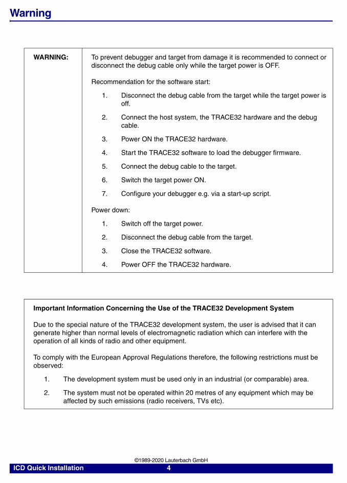
WARNING: To prevent debugger and target from damage it is recommended to connect or disconnect the debug cable only while the target power is OFF.
Recommendation for the software start:
1. Disconnect the debug cable from the target while the target power is off.
2. Connect the host system, the TRACE32 hardware and the debug cable.
3. Power ON the TRACE32 hardware.
4. Start the TRACE32 software to load the debugger firmware.
5. Connect the debug cable to the target.
6. Switch the target power ON.
7. Configure your debugger e.g. via a start-up script.
Power down:
1. Switch off the target power.
2. Disconnect the debug cable from the target.
3. Close the TRACE32 software.
4. Power OFF the TRACE32 hardware.
Important Information Concerning the Use of the TRACE32 Development System
Due to the special nature of the TRACE32 development system, the user is advised that it can generate higher than normal levels of electromagnetic radiation which can interfere with the operation of all kinds of radio and other equipment.
To comply with the European Approval Regulations therefore, the following restrictions must be observed:
1. The development system must be used only in an industrial (or comparable) area.
2. The system must not be operated within 20 metres of any equipment which may be affected by such emissions (radio receivers, TVs etc).
ICD Quick Installation 4 ©1989-2020 Lauterbach GmbH
Introduction
This manual introduces the typical configurations for the TRACE32 hardware-based debug and trace tools and provides guidance on installing the TRACE32 software for this product group.
How This Manual is Organized
• Brief Overview of Documents for New Users: Informs new users about important architecture-independent and architecture-specific documents.
• Tool Configuration: Provides information about and illustrations of the TRACE32 debug and trace tools.
• Software Installation: Describes the default installation of TRACE32 under MS Windows and PC Linux, Mac OS and SunOS.
Contacting Support
LAUTERBACH GmbHAltlaufstrasse 4085635 Hoehenkirchen-SiegertsbrunnGermany
Be sure to include detailed system information about your TRACE32 configuration.
1. To generate a system information report, choose TRACE32 > Help > Support > Systeminfo.
Phone (+49) 8102-9876-555
Fax (+49) 8102-9876-187
Internet https://www.lauterbach.com/tsupport.html or https://www.lauterbach.com/report.html Here you’ll find local and special support addresses.
E-mail [email protected] support address where your request will be answered within a short time if it is a basic support request or redirected to the appropriate address.
ICD Quick Installation 5 ©1989-2020 Lauterbach GmbH
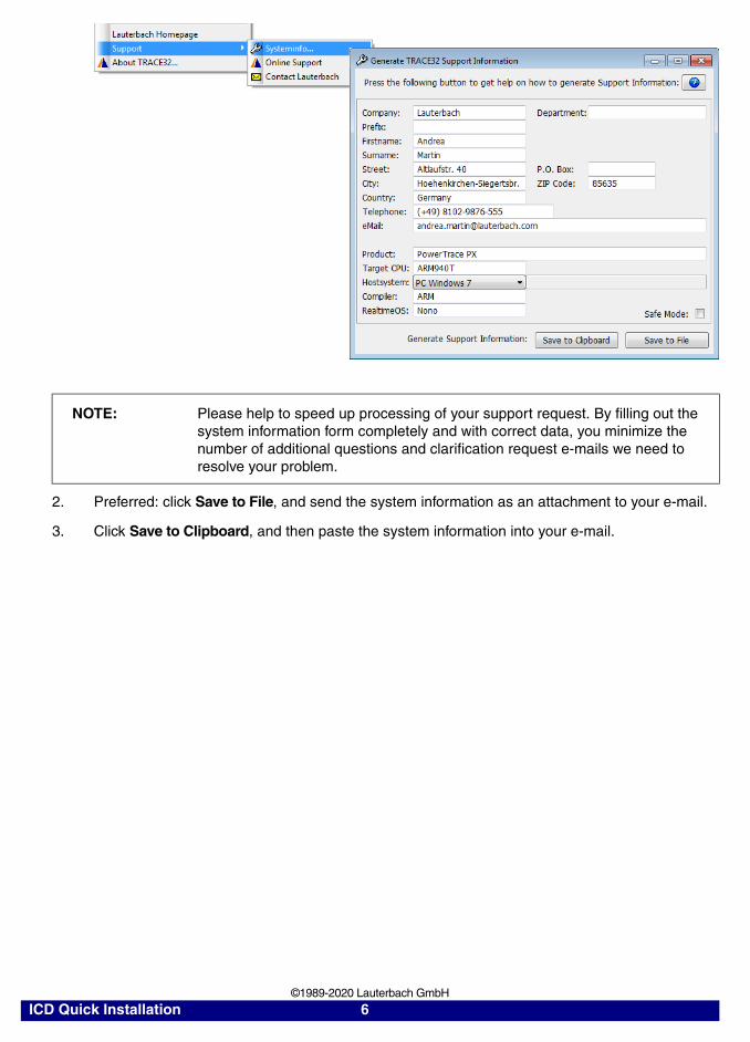
2. Preferred: click Save to File, and send the system information as an attachment to your e-mail.
3. Click Save to Clipboard, and then paste the system information into your e-mail.
NOTE: Please help to speed up processing of your support request. By filling out the system information form completely and with correct data, you minimize the number of additional questions and clarification request e-mails we need to resolve your problem.
ICD Quick Installation 6 ©1989-2020 Lauterbach GmbH
Brief Overview of Documents for New Users
Architecture-independent information:
• “Debugger Basics - Training” (training_debugger.pdf): Get familiar with the basic features of a TRACE32 debugger.
• “T32Start” (app_t32start.pdf): T32Start assists you in starting TRACE32 PowerView instances for different configurations of the debugger. T32Start is only available for Windows.
• “General Commands” (general_ref_<x>.pdf): Alphabetic list of debug commands.
Architecture-specific information:
• “Processor Architecture Manuals”: These manuals describe commands that are specific for the processor architecture supported by your debug cable. To access the manual for your processor architecture, proceed as follows:
- Choose Help menu > Processor Architecture Manual.
• “OS Awareness Manuals” (rtos_<os>.pdf): TRACE32 PowerView can be extended for operating system-aware debugging. The appropriate OS Awareness manual informs you how to enable the OS-aware debugging.
ICD Quick Installation 7 ©1989-2020 Lauterbach GmbH
Tool Configuration
This chapter gives a brief overview of typical TRACE32 tool configurations. Your final tool configuration can, of course, be more complex, especially if adapters or converters are needed.
Power Supply
When your TRACE32 hardware is delivered, you will receive one of the following power supplies:
• Wall Mount Power Supply
The Wall Mount Power Supply is delivered with the PowerDebug Module USB 3.0 and the uTrace.
• Desktop Power Supply
Please ONLY use the delivered power supplies. The following schematic drawings for the basic configuration always show the power supply to be used.
If you want to cascade several modules, please contact our support (https://www.lauterbach.com/tsupport.html) to find out which power supply must be used.
TRACE32 Debug Tools
A TRACE32 hardware-based debugger consists of:
• A universal debugger hardware
• A debug cable specific to the (main) processor architecture under debug;
The debug cable can contain a multicore license or debug licenses for further processor architectures if a multicore chip should be debugged. It can also contain traces licenses mainly used to decode core trace information stored in an onchip trace RAM.
ICD Quick Installation 8 ©1989-2020 Lauterbach GmbH
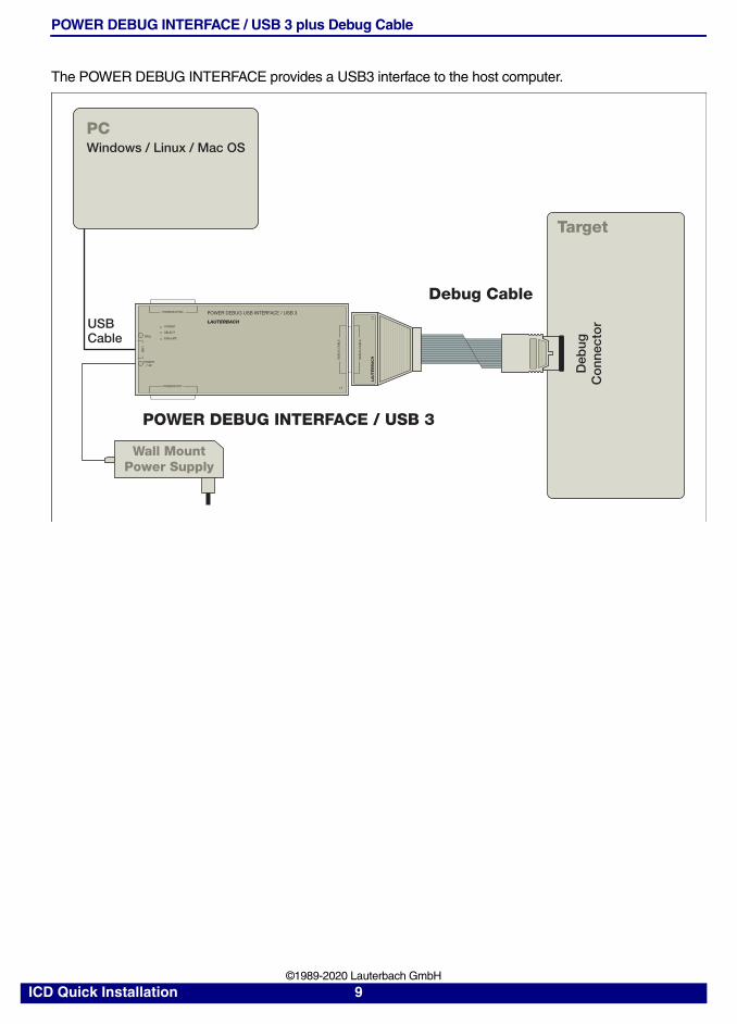
POWER DEBUG INTERFACE / USB 3 plus Debug Cable
The POWER DEBUG INTERFACE provides a USB3 interface to the host computer.
Target
DE
BU
G C
AB
LE
LA
UT
ER
BA
CH
Debug Cable
POWER DEBUG INTERFACE / USB 3
Wall MountPower Supply
PC
USBCable
LAUTERBACHPOWER
SELECT
EMULATE
PODBUS OUT
US
B
PODBUS SYNC
DE
BU
G C
AB
LE
POWER7-9V
TRIG
POWER DEBUG USB INTERFACE / USB 3
Deb
ugC
onn
ecto
r
Windows / Linux / Mac OS
ICD Quick Installation 9 ©1989-2020 Lauterbach GmbH
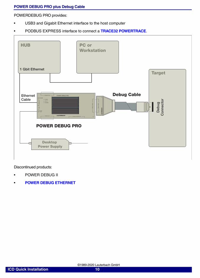
POWER DEBUG PRO plus Debug Cable
POWERDEBUG PRO provides:
• USB3 and Gigabit Ethernet interface to the host computer
• PODBUS EXPRESS interface to connect a TRACE32 POWERTRACE.
Discontinued products:
• POWER DEBUG II
• POWER DEBUG ETHERNET
Target
Debug Cable
POWER DEBUG PRO
Desktop Power Supply
EthernetCable
DE
BU
G C
AB
LE
LA
UT
ER
BA
CH
LAUTERBACH
POWER
SELECT
RUNNING
PODBUS OUT
ET
HE
RN
ET
US
B
PODBUS SYNC
DE
BU
G C
AB
LE
PODBUS EXPRESS OUT
POWER7-9V
TRIGGER
POWER DEBUG PRO
HUB PC orWorkstation
1 Gbit Ethernet
Deb
ugC
onn
ecto
r
ICD Quick Installation 10 ©1989-2020 Lauterbach GmbH
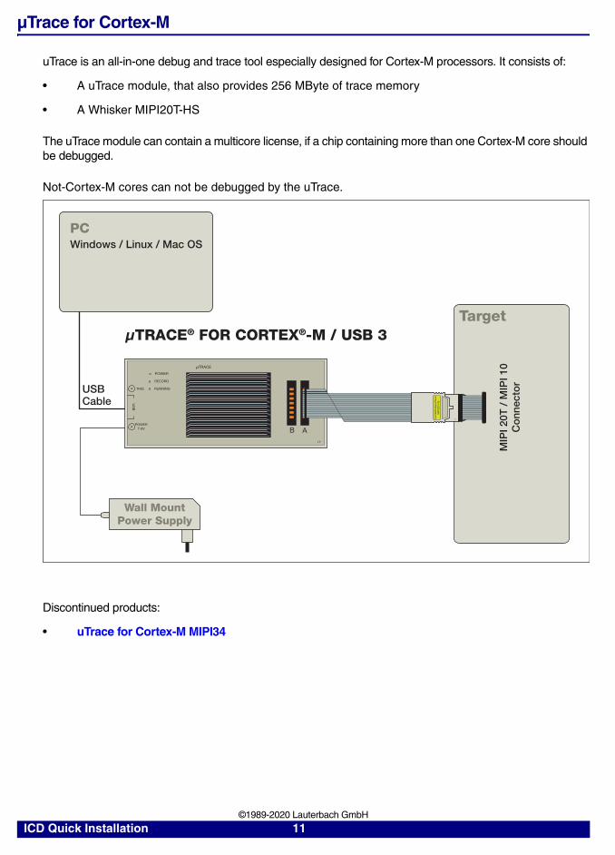
µTrace for Cortex-M
uTrace is an all-in-one debug and trace tool especially designed for Cortex-M processors. It consists of:
• A uTrace module, that also provides 256 MByte of trace memory
• A Whisker MIPI20T-HS
The uTrace module can contain a multicore license, if a chip containing more than one Cortex-M core should be debugged.
Not-Cortex-M cores can not be debugged by the uTrace.
Discontinued products:
• uTrace for Cortex-M MIPI34
Target
USBCable
μTRACE® FOR CORTEX®-M / USB 3
TRIG
POWER7-9V
POWER
RECORD
RUNNING
μTRACE
B A
US
B
PCWindows / Linux / Mac OS
MIP
I 20T
/ M
IPI 1
0C
onn
ecto
r
Com
biP
rob
e/μT
race
MIP
I20T
-HS
1
Wall MountPower Supply
ICD Quick Installation 11 ©1989-2020 Lauterbach GmbH
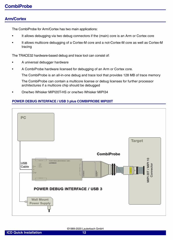
CombiProbe
Arm/Cortex
The CombiProbe for Arm/Cortex has two main applications:
• It allows debugging via two debug connectors if the (main) core is an Arm or Cortex core
• It allows multicore debugging of a Cortex-M core and a not-Cortex-M core as well as Cortex-M tracing
The TRACE32 hardware-based debug and trace tool can consist of:
• A universal debugger hardware
• A CombiProbe hardware licensed for debugging of an Arm or Cortex core.
The CombiProbe is an all-in-one debug and trace tool that provides 128 MB of trace memory
The CombiProbe can contain a multicore license or debug licenses for further processor architectures if a multicore chip should be debugged
• One/two Whisker MIPI20T-HS or one/two Whisker MIPI34
POWER DEBUG INTERFACE / USB 3 plus COMBIPROBE MIPI20T
Target
CombiProbe
POWER DEBUG INTERFACE / USB 3
PC
USBCable
LAUTERBACHPOWER
SELECT
EMULATE
PODBUS OUT
US
B
PODBUS SYNC
DE
BU
G C
AB
LE
POWER7-9V
TRIG
POWER DEBUG USB INTERFACE / USB 3
LA
UT
ER
BA
CH
LA
UT
ER
BA
CH
CO
MB
IPR
OB
E
MIP
I 20T
/ M
IPI 1
0C
onn
ecto
r
Com
biP
rob
e/μT
race
MIP
I20T
-HS
1
Wall MountPower Supply
ICD Quick Installation 12 ©1989-2020 Lauterbach GmbH
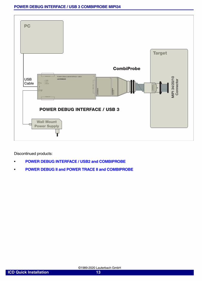
POWER DEBUG INTERFACE / USB 3 COMBIPROBE MIPI34
Discontinued products:
• POWER DEBUG INTERFACE / USB2 and COMBIPROBE
• POWER DEBUG II and POWER TRACE II and COMBIPROBE
Target
CombiProbe
POWER DEBUG INTERFACE / USB 3
PC
USBCable
Com
biP
rob
e
LAUTERBACHPOWER
SELECT
EMULATE
PODBUS OUT
US
B
PODBUS SYNC
DE
BU
G C
AB
LE
POWER7-9V
TRIG
POWER DEBUG USB INTERFACE / USB 3
LA
UT
ER
BA
CH
LA
UT
ER
BA
CH
CO
MB
IPR
OB
E
MIP
I 34/
20/1
0C
onn
ecto
r
Wall MountPower Supply
ICD Quick Installation 13 ©1989-2020 Lauterbach GmbH
TRACE32 Debug and High-End Trace Tools
Tools with Parallel or Serial Preprocessors
A TRACE32 hardware-based debug and trace tool can consist of:
• The universal debugger hardware POWER DEBUG PRO
• A debug cable specific to the (main) processor architecture under debug;
The debug cable can contain a multicore license or debug licenses for further processor architectures if a multicore chip should be debugged.
• A universal trace module POWER TRACE II with 1 GByte, 2 GByte or 4 GByte of trace memory or POWER TRACE II LITE with 512 MByte of trace memory
• A parallel or serial preprocessor specific to the processor architecture and its trace protocol
The preprocessor can contain trace licenses for further processor architectures if a multicore chip exports trace information in various trace protocols.
ICD Quick Installation 14 ©1989-2020 Lauterbach GmbH
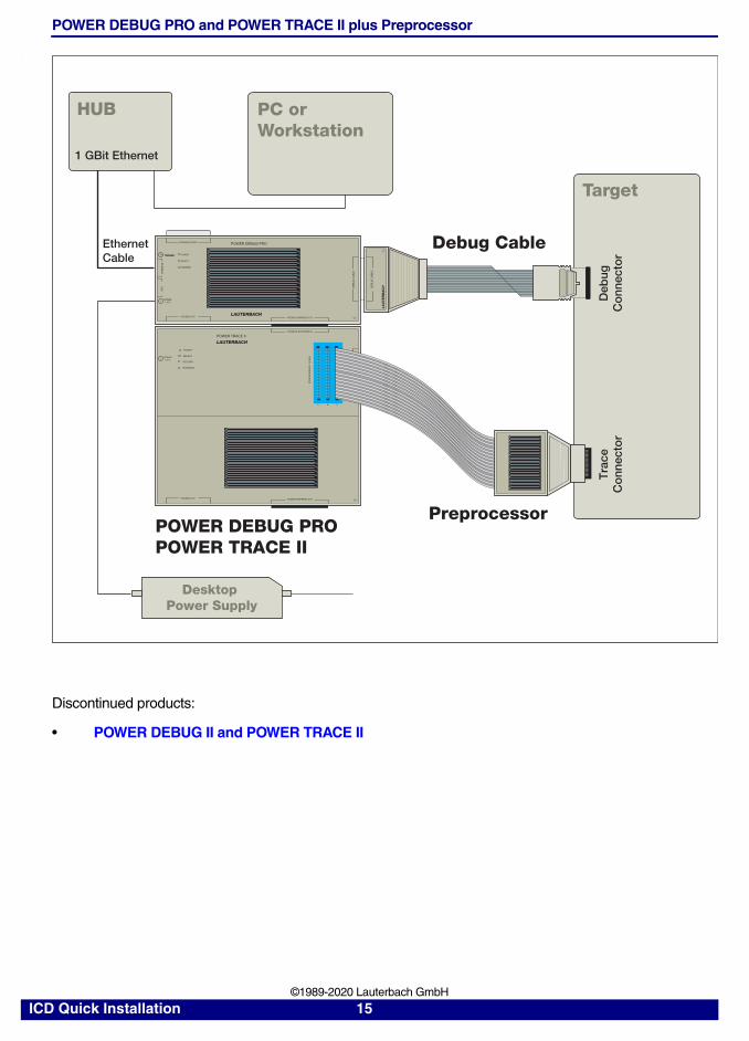
POWER DEBUG PRO and POWER TRACE II plus Preprocessor
.
Discontinued products:
• POWER DEBUG II and POWER TRACE II
Target
Debug Cable
Preprocessor
DE
BU
G C
AB
LE
LA
UT
ER
BA
CH
Deb
ugC
onn
ecto
rT
race
Co
nnec
tor
POWER DEBUG PRO
TRIGGERTRIGGER
DE
BU
G C
AB
LE
POWER7-9 V
PODBUS SYNC
PODBUS OUT
POWER
SELECT
RUNNING
PODBUS EXPRESS OUTLAUTERBACH
POWER7-9 V
PODBUS OUT PODBUS EXPRESS OUT
POWER
SELECT
RECORD
RUNNING
PODBUS EXPRESS IN
POWER TRACE II
LAUTERBACH
C B A
PR
EP
RO
CE
SS
OR
/ N
EX
US
POWER DEBUG PROPOWER TRACE II
EthernetCable
HUB PC orWorkstation
1 GBit Ethernet
LOG
IC A
NA
LYZ
ER
PR
OB
E
US
BE
THE
RN
ET
Desktop Power Supply
ICD Quick Installation 15 ©1989-2020 Lauterbach GmbH
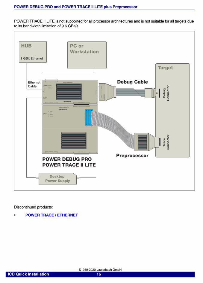
POWER DEBUG PRO and POWER TRACE II LITE plus Preprocessor
POWER TRACE II LITE is not supported for all processor architectures and is not suitable for all targets due to its bandwidth limitation of 9.6 GBit/s.
Discontinued products:
• POWER TRACE / ETHERNET
DE
BU
G C
AB
LE
LA
UT
ER
BA
CH
Target
POWER DEBUG PRO
TRIGGERTRIGGER
DE
BU
G C
AB
LE
POWER7-9 V
PODBUS SYNC
PODBUS OUT
POWER
SELECT
RUNNING
PODBUS EXPRESS OUTLAUTERBACH
POWER7-9 V
PODBUS OUT PODBUS EXPRESS OUT
POWER
SELECT
RECORD
RUNNING
PODBUS EXPRESS IN
POWER TRACE II LITE
LAUTERBACH
C B A
PR
EP
RO
CE
SS
OR
/ N
EX
US
POWER DEBUG PROPOWER TRACE II LITE
EthernetCable
Debug Cable
HUB PC orWorkstation
1 GBit Ethernet
LOG
IC A
NA
LYZ
ER
PR
OB
E
US
BE
THE
RN
ET
Deb
ugC
onn
ecto
rT
race
Co
nnec
tor
Preprocessor
Desktop Power Supply
ICD Quick Installation 16 ©1989-2020 Lauterbach GmbH
Tools with Parallel NEXUS Adapter
A TRACE32 hardware-based debug and trace tool can consist of:
• The universal debugger hardware POWER DEBUG PRO
• A universal trace module POWER TRACE II with 1 GByte, 2 GByte or 4 GByte trace memory or POWER TRACE II LITE with 512 MByte of trace memory
• A parallel NEXUS adapter specific for the processor architecture under debug and trace
The NEXUS adapter can contain debug/trace licenses for further processor architectures if a multicore chip is under debug
ICD Quick Installation 17 ©1989-2020 Lauterbach GmbH
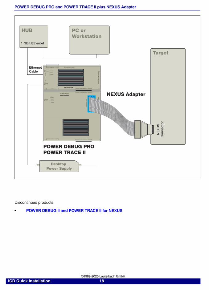
POWER DEBUG PRO and POWER TRACE II plus NEXUS Adapter
Discontinued products:
• POWER DEBUG II and POWER TRACE II for NEXUS
Target
NE
XU
SC
onn
ecto
r
POWER DEBUG PRO
TRIGGERTRIGGER
US
B DE
BU
G C
AB
LE
ETH
ER
NE
T
POWER7-9 V
PODBUS SYNC
PODBUS OUT
POWER
SELECT
RUNNING
PODBUS EXPRESS OUTLAUTERBACH
POWER7-9 V
PODBUS OUT PODBUS EXPRESS OUT
POWER
SELECT
RECORD
RUNNING
PODBUS EXPRESS IN
POWER TRACE II
LAUTERBACH
C B A
PR
EP
RO
CE
SS
OR
/ N
EX
US
POWER DEBUG PROPOWER TRACE II
EthernetCable
HUB PC orWorkstation
1 GBit Ethernet
LOG
IC A
NA
LYZ
ER
PR
OB
E
NEXUS Adapter
Desktop Power Supply
ICD Quick Installation 18 ©1989-2020 Lauterbach GmbH
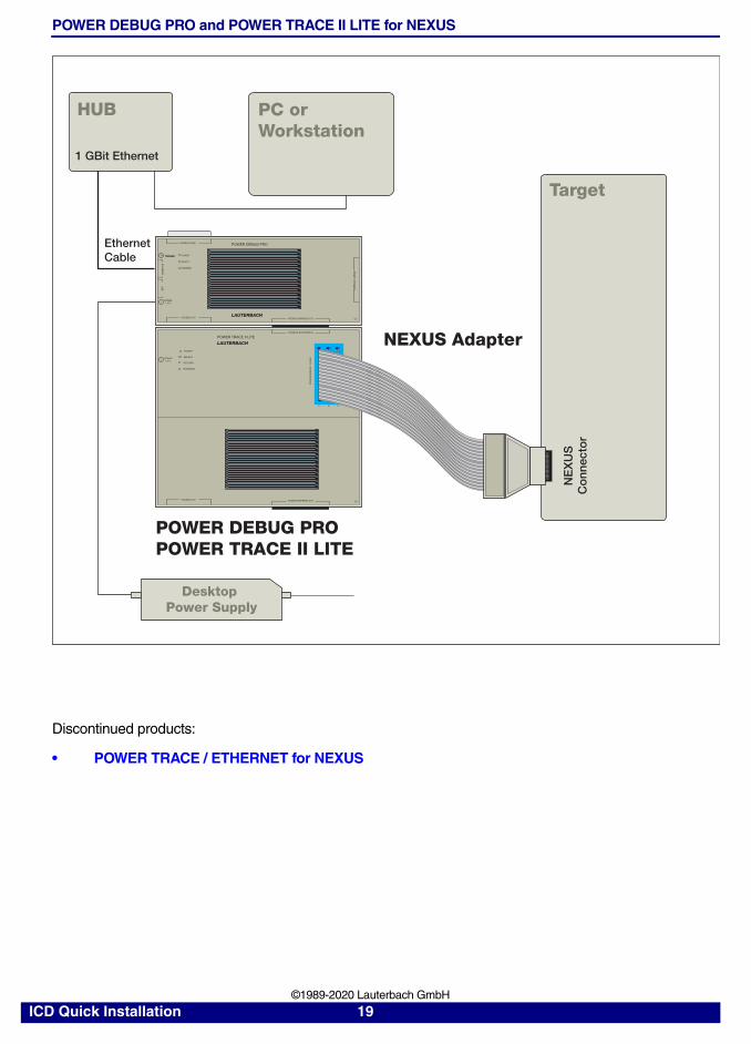
POWER DEBUG PRO and POWER TRACE II LITE for NEXUS
Discontinued products:
• POWER TRACE / ETHERNET for NEXUS
Target
NE
XU
SC
onn
ecto
r
TRIGGERTRIGGER
DE
BU
G C
AB
LE
POWER7-9 V
PODBUS OUT
POWER
SELECT
RUNNING
PODBUS EXPRESS OUTLAUTERBACH
POWER7-9 V
PODBUS OUT PODBUS EXPRESS OUT
POWER
SELECT
RECORD
RUNNING
PODBUS EXPRESS IN
POWER TRACE II LITE
LAUTERBACH
C B A
PR
EP
RO
CE
SS
OR
/ N
EX
US
POWER DEBUG PROPOWER TRACE II LITE
HUB PC orWorkstation
1 GBit Ethernet
NEXUS Adapter
POWER DEBUG PRO
US
BE
THE
RN
ET
PODBUS SYNCEthernetCable
Desktop Power Supply
ICD Quick Installation 19 ©1989-2020 Lauterbach GmbH
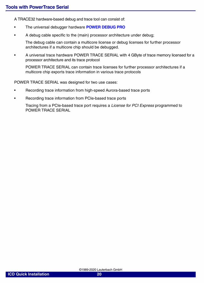
Tools with PowerTrace Serial
A TRACE32 hardware-based debug and trace tool can consist of:
• The universal debugger hardware POWER DEBUG PRO
• A debug cable specific to the (main) processor architecture under debug;
The debug cable can contain a multicore license or debug licenses for further processor architectures if a multicore chip should be debugged.
• A universal trace hardware POWER TRACE SERIAL with 4 GByte of trace memory licensed for a processor architecture and its trace protocol
POWER TRACE SERIAL can contain trace licenses for further processor architectures if a multicore chip exports trace information in various trace protocols
POWER TRACE SERIAL was designed for two use cases:
• Recording trace information from high-speed Aurora-based trace ports
• Recording trace information from PCIe-based trace ports
Tracing from a PCIe-based trace port requires a License for PCI Express programmed to POWER TRACE SERIAL
ICD Quick Installation 20 ©1989-2020 Lauterbach GmbH
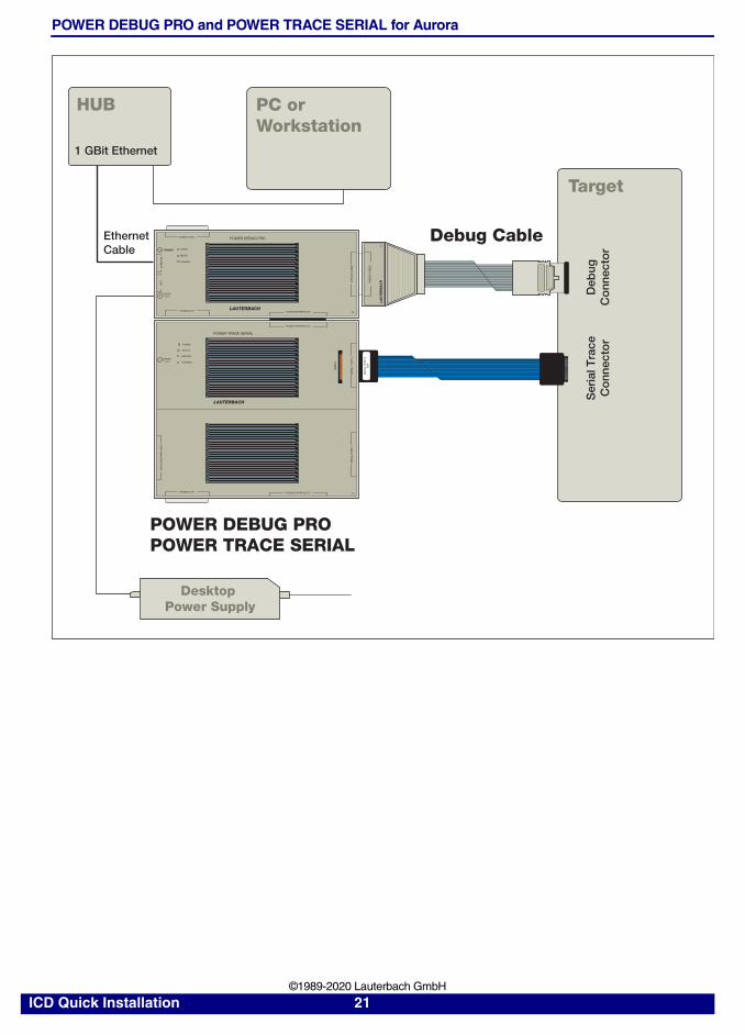
POWER DEBUG PRO and POWER TRACE SERIAL for Aurora
HUB PC orWorkstation
1 GBit Ethernet
EthernetCable
Target
POWER7-9 V
SE
RIA
L P
OR
T 0
DE
BU
G
SE
RIA
L P
OR
T 0
TOP
PODBUS OUT
LOG
IC A
NA
LYZ
ER
PR
OB
E
PODBUS EXPRESS OUT
POWER
SELECT
RECORD
RUNNING
POWER TRACE SERIAL
LAUTERBACH
SE
RIA
L P
OR
T 1
DE
BU
G C
AB
LE
LA
UT
ER
BA
CH
Deb
ugC
onn
ecto
rS
eria
l Tra
ceC
onn
ecto
r
Debug CablePOWER DEBUG PRO
TRIGGERTRIGGER
US
B
DE
BU
G C
AB
LE
ETH
ER
NE
T
POWER7-9 V
PODBUS SYNC
PODBUS OUT
POWER
SELECT
RUNNING
PODBUS EXPRESS OUTLAUTERBACH
POWER TRACE SERIAL
PODBUS EXPRESS OUT
POWER DEBUG PRO
Desktop Power Supply
ICD Quick Installation 21 ©1989-2020 Lauterbach GmbH
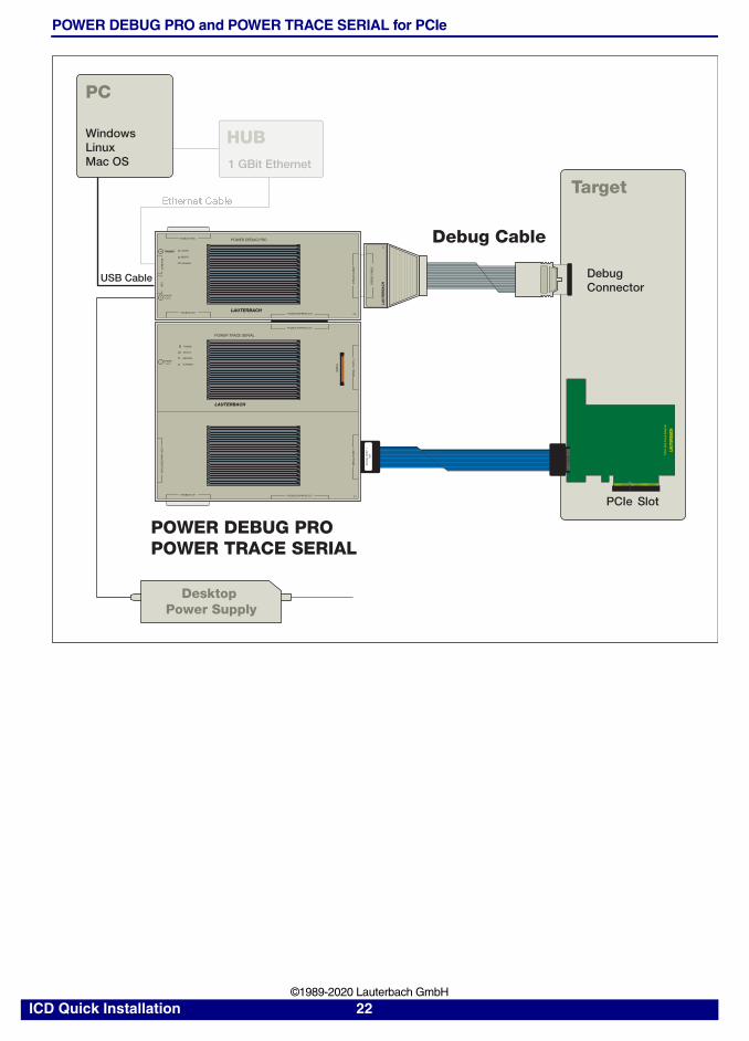
POWER DEBUG PRO and POWER TRACE SERIAL for PCIe
HUB
PC
1 GBit Ethernet
WindowsLinuxMac OS
USB Cable
Target
POWER7-9 V
SE
RIA
L P
OR
T 0
DE
BU
G
SE
RIA
L P
OR
T 1
TOP
PODBUS OUT
LOG
IC A
NA
LYZ
ER
PR
OB
E
PODBUS EXPRESS OUT
POWER
SELECT
RECORD
RUNNING
POWER TRACE SERIAL
LAUTERBACH
SE
RIA
L P
OR
T 1
DE
BU
G C
AB
LE
LA
UT
ER
BA
CH
DebugConnector
SlotPCIe
Debug CablePOWER DEBUG PRO
TRIGGERTRIGGER
US
B
DE
BU
G C
AB
LE
ETH
ER
NE
T
POWER7-9 V
PODBUS SYNC
PODBUS OUT
POWER
SELECT
RUNNING
PODBUS EXPRESS OUTLAUTERBACH
POWER TRACE SERIAL
PODBUS EXPRESS OUT
POWER DEBUG PRO
LAUT
ERBA
CHP
CIe
Slo
t-C
ard-
Ada
pter
Desktop Power Supply
ICD Quick Installation 22 ©1989-2020 Lauterbach GmbH
Software Installation
This chapter describes the installation of TRACE32 under:
• MS Windows
- Quick Installation
- Ethernet
- USB
• PC_Linux
- Ethernet
- USB
• Mac OS
• SunOS, Solaris (SUN), HP-UX
ICD Quick Installation 23 ©1989-2020 Lauterbach GmbH
MS Windows
Quick Installation
1. Insert the installation DVD into the DVD drive.
2. Install TRACE32 by double-clicking “setup.bat” or “files\bin\setup64\setup.exe” (WIN2000/XP/WIN Server 2003/WIN Vista/WIN7/WIN8/WIN10).
3. Follow the on-screen instructions.
4. Upon completion of the installation, start TRACE32 via the Windows Start button as described in “ICD Tutorial” (icd_tutorial.pdf).
In multicore/multiprocessor debug environments, it is recommended that Windows users start TRACE32 via the T32Start application.
1. Start T32Start via the Windows Start button.
2. Configure T32Start according to your requirements. See chapter “Quick Start” (app_t32start.pdf).
3. Configure the TRACE32 help system with a few mouse-clicks to display the PDF help files in your favorite PDF viewer; see “Configure the Help System” (ide_user.pdf).
Ethernet
First a new node must be created for TRACE32. The Ethernet address of the emulator is on a sticker located on the reverse side of the system. The administrator must add an entry containing the IP address and node name to the name server, or the following line must be added to the file HOSTS:
Note, the above used INTERNET address is an example only. Contact your network administrator for a new INTERNET address for TRACE32.
The INTERNET address is requested by a DHCP/RARP protocol by TRACE32. If no DHCP/RARP server is running, the address for the first connect must be set in the host table. After the first successful connect the INTERNET address is stored in the non-volatile memory within TRACE32. The following command sets the host translation table:
If the ARP command is not available, the internet address must be set by connecting the system via fiber optic link or parallel interface or USB.
192.9.200.5 t32
arp -s t32 0-c0-8a-0-0-0
NOTE: On Windows the ARP command is only available if you are logged in as an administrator.
ICD Quick Installation 24 ©1989-2020 Lauterbach GmbH

To use the network access, the net driver must be activated. The node name can be changed, when not identical to 't32'.
USB Interface
The USB driver must be selected. Windows 2000 / XP or Vista or Windows 7 or Windows 8 or Windows 10 is required.
When the device is first connected to the system, the hardware assistant detects a new USB device and asks for a driver directory.
If the TRACE32 software is already installed, the required file (t32usb.inf) can be found in the TRACE32 installation directory (e.g. c:\t32\). Otherwise please insert the TRACE32 installation DVD and navigate to the directory ~~/bin/windows/drivers or let the system search for it.
Configuration Com-mand:
PBI=NET
Used for controller-based debugging
NODE=<node_name> (default: t32)
PACKLEN=1024 Limits the size of the UDP packages to 1024
Configuration Command:
PBI=USB
Select PODBUS interface via USB connection
PBI=USBNODE=T32-ARM
Select PODBUS interface via named USB connection
The PODBUS interface is identified by a name (IFCONFIG).A name is required if several debug modules are connectedvia USB and used simultaneously.The manufacturing default device name is the serial numberof the debug module. e.g. NODE=E18110012345
ICD Quick Installation 25 ©1989-2020 Lauterbach GmbH
PC_LINUX
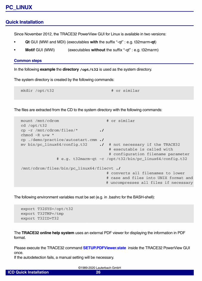
Quick Installation
Since November 2012, the TRACE32 PowerView GUI for Linux is available in two versions:
• Qt GUI (MWI and MDI) (executables with the suffix “-qt” : e.g. t32marm-qt)
• Motif GUI (MWI) (executables without the suffix “-qt” : e.g. t32marm)
Common steps
In the following example the directory /opt/t32 is used as the system directory.
The system directory is created by the following commands:
The files are extracted from the CD to the system directory with the following commands:
The following environment variables must be set (e.g. in .bashrc for the BASH-shell):
The TRACE32 online help system uses an external PDF viewer for displaying the information in PDF format.
Please execute the TRACE32 command SETUP.PDFViewer.state inside the TRACE32 PowerView GUI once.If the autodetection fails, a manual setting will be necessary.
mkdir /opt/t32 # or similar
mount /mnt/cdrom # or similarcd /opt/t32cp -r /mnt/cdrom/files/* ./chmod -R u+w *cp ./demo/practice/autostart.cmm ./mv bin/pc_linux64/config.t32 ./ # not necessary if the TRACE32 # executable is called with # configuration filename parameter # e.g. t32marm-qt -c /opt/t32/bin/pc_linux64/config.t32
/mnt/cdrom/files/bin/pc_linux64/filecvt ./ # converts all filenames to lower # case and files into UNIX format and # uncompresses all files if necessary
export T32SYS=/opt/t32export T32TMP=/tmpexport T32ID=T32
ICD Quick Installation 26 ©1989-2020 Lauterbach GmbH
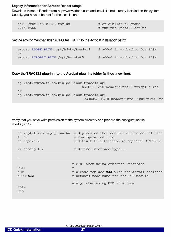
Legacy information for Acrobat Reader usage:
Download Acrobat Reader from http://www.adobe.com and install it if not already installed on the system. Usually, you have to be root for the installation!
Set the environment variable “ACROBAT_PATH” to the Acrobat installation path::
Copy the TRACE32 plug-in into the Acrobat plug_ins folder (without new line):
Verify that you have write permission to the system directory and prepare the configuration file config.t32:
tar -xvzf linux-508.tar.gz # or similar filename./INSTALL # run the install script
export ADOBE_PATH=/opt/Adobe/Reader8 # added in ~/.bashrc for BASHorexport ACROBAT_PATH=/opt/Acrobat5 # added in ~/.bashrc for BASH
cp /mnt/cdrom/files/bin/pc_linux/trace32.api $ADOBE_PATH/Reader/intellinux/plug_insorcp /mnt/cdrom/files/bin/pc_linux/trace32.api $ACROBAT_PATH/Reader/intellinux/plug_ins
cd /opt/t32/bin/pc_linux64 # depends on the location of the actual used# or # configuration filecd /opt/t32 # default file location is /opt/t32 ($T32SYS)
vi config.t32 # define interface type, …
…
# e.g. when using ethernet interfacePBI= #NET # please replace t32 with the actual assignedNODE=t32 # network node name for the ICD module
# e.g. when using USB interfacePBI=USB
ICD Quick Installation 27 ©1989-2020 Lauterbach GmbH
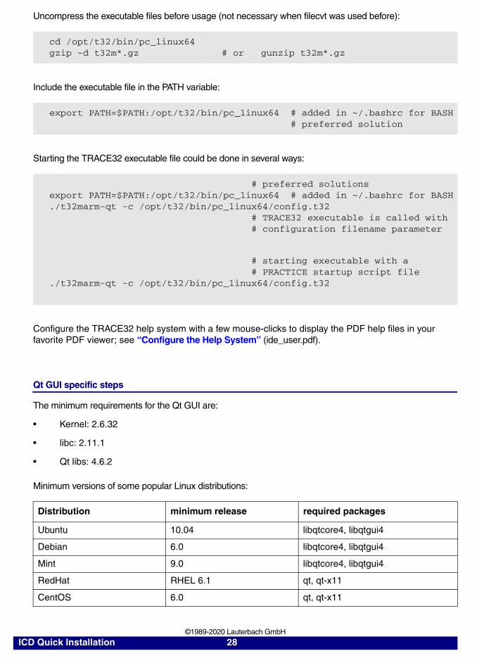
Uncompress the executable files before usage (not necessary when filecvt was used before):
Include the executable file in the PATH variable:
Starting the TRACE32 executable file could be done in several ways:
Configure the TRACE32 help system with a few mouse-clicks to display the PDF help files in your favorite PDF viewer; see “Configure the Help System” (ide_user.pdf).
Qt GUI specific steps
The minimum requirements for the Qt GUI are:
• Kernel: 2.6.32
• libc: 2.11.1
• Qt libs: 4.6.2
Minimum versions of some popular Linux distributions:
cd /opt/t32/bin/pc_linux64gzip -d t32m*.gz # or gunzip t32m*.gz
export PATH=$PATH:/opt/t32/bin/pc_linux64 # added in ~/.bashrc for BASH # preferred solution
# preferred solutionsexport PATH=$PATH:/opt/t32/bin/pc_linux64 # added in ~/.bashrc for BASH./t32marm-qt -c /opt/t32/bin/pc_linux64/config.t32 # TRACE32 executable is called with # configuration filename parameter
# starting executable with a # PRACTICE startup script file./t32marm-qt -c /opt/t32/bin/pc_linux64/config.t32
Distribution minimum release required packages
Ubuntu 10.04 libqtcore4, libqtgui4
Debian 6.0 libqtcore4, libqtgui4
Mint 9.0 libqtcore4, libqtgui4
RedHat RHEL 6.1 qt, qt-x11
CentOS 6.0 qt, qt-x11
ICD Quick Installation 28 ©1989-2020 Lauterbach GmbH
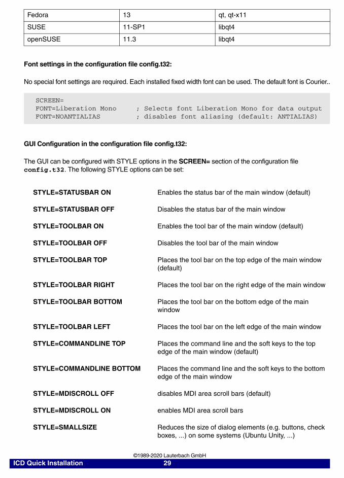
Font settings in the configuration file config.t32:
No special font settings are required. Each installed fixed width font can be used. The default font is Courier..
GUI Configuration in the configuration file config.t32:
The GUI can be configured with STYLE options in the SCREEN= section of the configuration file config.t32. The following STYLE options can be set:
Fedora 13 qt, qt-x11
SUSE 11-SP1 libqt4
openSUSE 11.3 libqt4
SCREEN=FONT=Liberation MonoFONT=NOANTIALIAS
; Selects font Liberation Mono for data output; disables font aliasing (default: ANTIALIAS)
STYLE=STATUSBAR ON Enables the status bar of the main window (default)
STYLE=STATUSBAR OFF Disables the status bar of the main window
STYLE=TOOLBAR ON Enables the tool bar of the main window (default)
STYLE=TOOLBAR OFF Disables the tool bar of the main window
STYLE=TOOLBAR TOP Places the tool bar on the top edge of the main window (default)
STYLE=TOOLBAR RIGHT Places the tool bar on the right edge of the main window
STYLE=TOOLBAR BOTTOM Places the tool bar on the bottom edge of the main window
STYLE=TOOLBAR LEFT Places the tool bar on the left edge of the main window
STYLE=COMMANDLINE TOP Places the command line and the soft keys to the top edge of the main window (default)
STYLE=COMMANDLINE BOTTOM Places the command line and the soft keys to the bottom edge of the main window
STYLE=MDISCROLL OFF disables MDI area scroll bars (default)
STYLE=MDISCROLL ON enables MDI area scroll bars
STYLE=SMALLSIZE Reduces the size of dialog elements (e.g. buttons, check boxes, ...) on some systems (Ubuntu Unity, ...)
ICD Quick Installation 29 ©1989-2020 Lauterbach GmbH
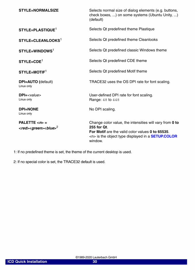
1: If no predefined theme is set, the theme of the current desktop is used.
2: If no special color is set, the TRACE32 default is used.
STYLE=NORMALSIZE Selects normal size of dialog elements (e.g. buttons, check boxes, ...) on some systems (Ubuntu Unity, ...) (default)
STYLE=PLASTIQUE1 Selects Qt predefined theme Plastique
STYLE=CLEANLOOKS1 Selects Qt predefined theme Cleanlooks
STYLE=WINDOWS1 Selects Qt predefined classic Windows theme
STYLE=CDE1 Selects Qt predefined CDE theme
STYLE=MOTIF1 Selects Qt predefined Motif theme
DPI=AUTO (default) Linux only
TRACE32 uses the OS DPI rate for font scaling.
DPI=<value> Linux only
User-defined DPI rate for font scaling.Range: 48 to 448
DPI=NONELinux only
No DPI scaling.
PALETTE <n> = <red><green><blue>2
Change color value, the intensities will vary from 0 to 255 for Qt.For Motif are the valid color values 0 to 65535.<n> is the object type displayed in a SETUP.COLOR window.
ICD Quick Installation 30 ©1989-2020 Lauterbach GmbH
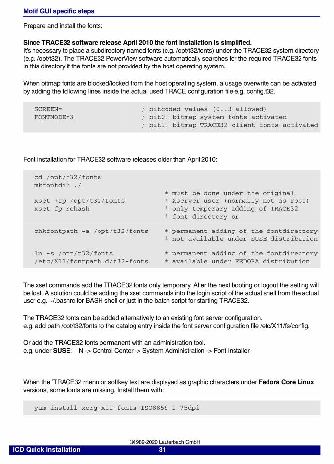
Motif GUI specific steps
Prepare and install the fonts:
Since TRACE32 software release April 2010 the font installation is simplified. It’s necessary to place a subdirectory named fonts (e.g. /opt/t32/fonts) under the TRACE32 system directory (e.g. /opt/t32). The TRACE32 PowerView software automatically searches for the required TRACE32 fonts in this directory if the fonts are not provided by the host operating system.
When bitmap fonts are blocked/locked from the host operating system, a usage overwrite can be activated by adding the following lines inside the actual used TRACE configuration file e.g. config.t32.
Font installation for TRACE32 software releases older than April 2010:
The xset commands add the TRACE32 fonts only temporary. After the next booting or logout the setting will be lost. A solution could be adding the xset commands into the login script of the actual shell from the actual user e.g. ~/.bashrc for BASH shell or just in the batch script for starting TRACE32.
The TRACE32 fonts can be added alternatively to an existing font server configuration.e.g. add path /opt/t32/fonts to the catalog entry inside the font server configuration file /etc/X11/fs/config.
Or add the TRACE32 fonts permanent with an administration tool.e.g. under SUSE: N -> Control Center -> System Administration -> Font Installer
When the ’TRACE32 menu or softkey text are displayed as graphic characters under Fedora Core Linux versions, some fonts are missing. Install them with:
SCREEN=FONTMODE=3
; bitcoded values (0..3 allowed); bit0: bitmap system fonts activated; bit1: bitmap TRACE32 client fonts activated
cd /opt/t32/fontsmkfontdir ./
xset +fp /opt/t32/fontsxset fp rehash
# must be done under the original# Xserver user (normally not as root)# only temporary adding of TRACE32# font directory or
chkfontpath -a /opt/t32/fonts # permanent adding of the fontdirectory# not available under SUSE distribution
ln -s /opt/t32/fonts /etc/X11/fontpath.d/t32-fonts
# permanent adding of the fontdirectory# available under FEDORA distribution
yum install xorg-x11-fonts-ISO8859-1-75dpi
ICD Quick Installation 31 ©1989-2020 Lauterbach GmbH

Ethernet Interface
Before the installation a new node must be created. The Ethernet address of the system is placed on the bottom side of the system. The following line must be added to the file /etc/hosts:
Note that the INTERNET address given here is an example only. Contact your network administrator for a new INTERNET address for TRACE32.
The Ethernet address of the system must be entered in the file /etc/ethers (not common - only when using a RARP server):
The INTERNET address is requested by a RARP protocol by TRACE32. If no RARP server is running, the address for the first connect must be set in the host table. After the first successful connect the INTERNET address is stored in nonvolatile memory within TRACE32. The following command sets the host translation table:
This command must be executed immediately before the first startup of the emulator. It is not required for future startups because the INTERNET address is stored in the emulator. The arp cache table should be checked just before the first startup with the command 'arp -a'.
NOTE: A ping will only work after the TRACE32 software was booted once and the new IP address was stored automatically during boot phase into the flash of the TRACE32 modul.
The net driver must be activated. The node name can be changed, when not identical to 't32'.
192.168.0.5 t32
0:c0:8a:0:0:0 t32
arp -s t32 0:c0:8a:0:0:0
Configuration Command:
PBI=NET
NODE=<node_name> Node name of TRACE32 (default: t32)
POOL=<node_name>, … Define a set of nodes, which are scanned for connection.
ICD Quick Installation 32 ©1989-2020 Lauterbach GmbH
USB Interface
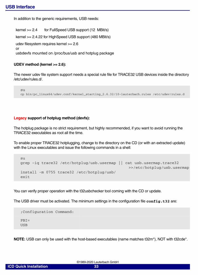
In addition to the generic requirements, USB needs:
UDEV method (kernel >= 2.6):
The newer udev file system support needs a special rule file for TRACE32 USB devices inside the directory /etc/udev/rules.d/.
Legacy support of hotplug method (devfs):
The hotplug package is no strict requirement, but highly recommended, if you want to avoid running the TRACE32 executables as root all the time.
To enable proper TRACE32 hotplugging, change to the directory on the CD (or with an extracted update) with the Linux executables and issue the following commands in a shell:
You can verify proper operation with the t32usbchecker tool coming with the CD or update.
The USB driver must be activated. The minimum settings in the configuration file config.t32 are:
NOTE: USB can only be used with the host-based executables (name matches t32m*), NOT with t32cde*.
kernel >= 2.4 for FullSpeed USB support (12 MBit/s)
kernel >= 2.4.22 for HighSpeed USB support (480 MBit/s)
udev filesystem requires kernel >= 2.6orusbdevfs mounted on /proc/bus/usb and hotplug package
sucp bin/pc_linux64/udev.conf/kernel_starting_2.6.32/10-lauterbach.rules /etc/udev/rules.d
sugrep -iq trace32 /etc/hotplug/usb.usermap || cat usb.usermap.trace32 >>/etc/hotplug/usb.usermapinstall -m 0755 trace32 /etc/hotplug/usb/exit
;Configuration Command:
PBI=USB
ICD Quick Installation 33 ©1989-2020 Lauterbach GmbH
Mac OS
Prerequisites
The TRACE32 debug software for the Mac requires OS X 10.7 or newer.
Installation of the TRACE32 Software
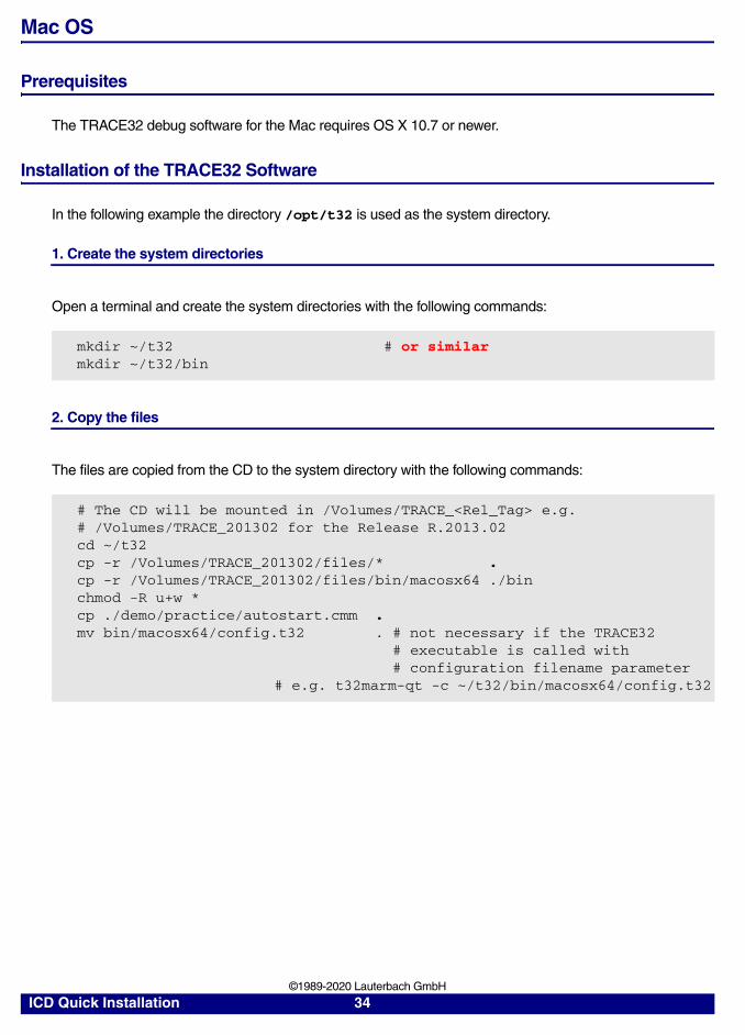
In the following example the directory /opt/t32 is used as the system directory.
1. Create the system directories
Open a terminal and create the system directories with the following commands:
2. Copy the files
The files are copied from the CD to the system directory with the following commands:
mkdir ~/t32 # or similarmkdir ~/t32/bin
# The CD will be mounted in /Volumes/TRACE_<Rel_Tag> e.g.# /Volumes/TRACE_201302 for the Release R.2013.02cd ~/t32cp -r /Volumes/TRACE_201302/files/* . cp -r /Volumes/TRACE_201302/files/bin/macosx64 ./binchmod -R u+w *cp ./demo/practice/autostart.cmm .mv bin/macosx64/config.t32 . # not necessary if the TRACE32 # executable is called with # configuration filename parameter # e.g. t32marm-qt -c ~/t32/bin/macosx64/config.t32
ICD Quick Installation 34 ©1989-2020 Lauterbach GmbH
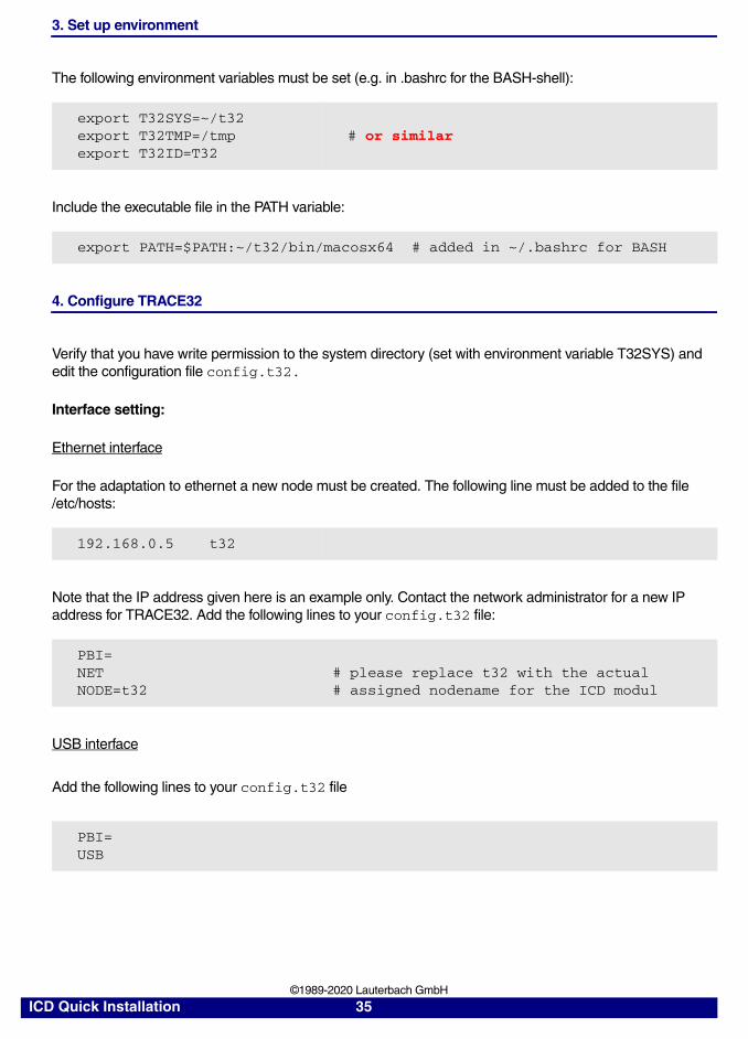
3. Set up environment
The following environment variables must be set (e.g. in .bashrc for the BASH-shell):
Include the executable file in the PATH variable:
4. Configure TRACE32
Verify that you have write permission to the system directory (set with environment variable T32SYS) and edit the configuration file config.t32.
Interface setting:
Ethernet interface
For the adaptation to ethernet a new node must be created. The following line must be added to the file /etc/hosts:
Note that the IP address given here is an example only. Contact the network administrator for a new IP address for TRACE32. Add the following lines to your config.t32 file:
USB interface
Add the following lines to your config.t32 file
export T32SYS=~/t32export T32TMP=/tmpexport T32ID=T32
# or similar
export PATH=$PATH:~/t32/bin/macosx64 # added in ~/.bashrc for BASH
192.168.0.5 t32
PBI=NET # please replace t32 with the actualNODE=t32 # assigned nodename for the ICD modul
PBI=USB
ICD Quick Installation 35 ©1989-2020 Lauterbach GmbH
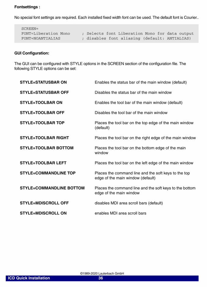
Fontsettings :
No special font settings are required. Each installed fixed width font can be used. The default font is Courier..
GUI Configuration:
The GUI can be configured with STYLE options in the SCREEN section of the configuration file. The following STYLE options can be set:
SCREEN=FONT=Liberation MonoFONT=NOANTIALIAS
; Selects font Liberation Mono for data output; disables font aliasing (default: ANTIALIAS)
STYLE=STATUSBAR ON Enables the status bar of the main window (default)
STYLE=STATUSBAR OFF Disables the status bar of the main window
STYLE=TOOLBAR ON Enables the tool bar of the main window (default)
STYLE=TOOLBAR OFF Disables the tool bar of the main window
STYLE=TOOLBAR TOP Places the tool bar on the top edge of the main window (default)
STYLE=TOOLBAR RIGHT Places the tool bar on the right edge of the main window
STYLE=TOOLBAR BOTTOM Places the tool bar on the bottom edge of the main window
STYLE=TOOLBAR LEFT Places the tool bar on the left edge of the main window
STYLE=COMMANDLINE TOP Places the command line and the soft keys to the top edge of the main window (default)
STYLE=COMMANDLINE BOTTOM Places the command line and the soft keys to the bottom edge of the main window
STYLE=MDISCROLL OFF disables MDI area scroll bars (default)
STYLE=MDISCROLL ON enables MDI area scroll bars
ICD Quick Installation 36 ©1989-2020 Lauterbach GmbH
SunOS, Solaris (SUN)
Please be aware that only network interfaces are supported (not USB).
Installation of the TRACE32 Debugger Software
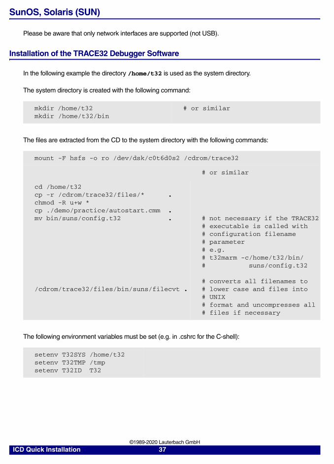
In the following example the directory /home/t32 is used as the system directory.
The system directory is created with the following command:
The files are extracted from the CD to the system directory with the following commands:
The following environment variables must be set (e.g. in .cshrc for the C-shell):
mkdir /home/t32 mkdir /home/t32/bin
# or similar
mount -F hsfs -o ro /dev/dsk/c0t6d0s2 /cdrom/trace32
# or similar
cd /home/t32cp -r /cdrom/trace32/files/* .chmod -R u+w *cp ./demo/practice/autostart.cmm .mv bin/suns/config.t32 .
/cdrom/trace32/files/bin/suns/filecvt .
# not necessary if the TRACE32# executable is called with# configuration filename# parameter# e.g. # t32marm -c/home/t32/bin/# suns/config.t32
# converts all filenames to# lower case and files into# UNIX# format and uncompresses all# files if necessary
setenv T32SYS /home/t32setenv T32TMP /tmpsetenv T32ID T32
ICD Quick Installation 37 ©1989-2020 Lauterbach GmbH
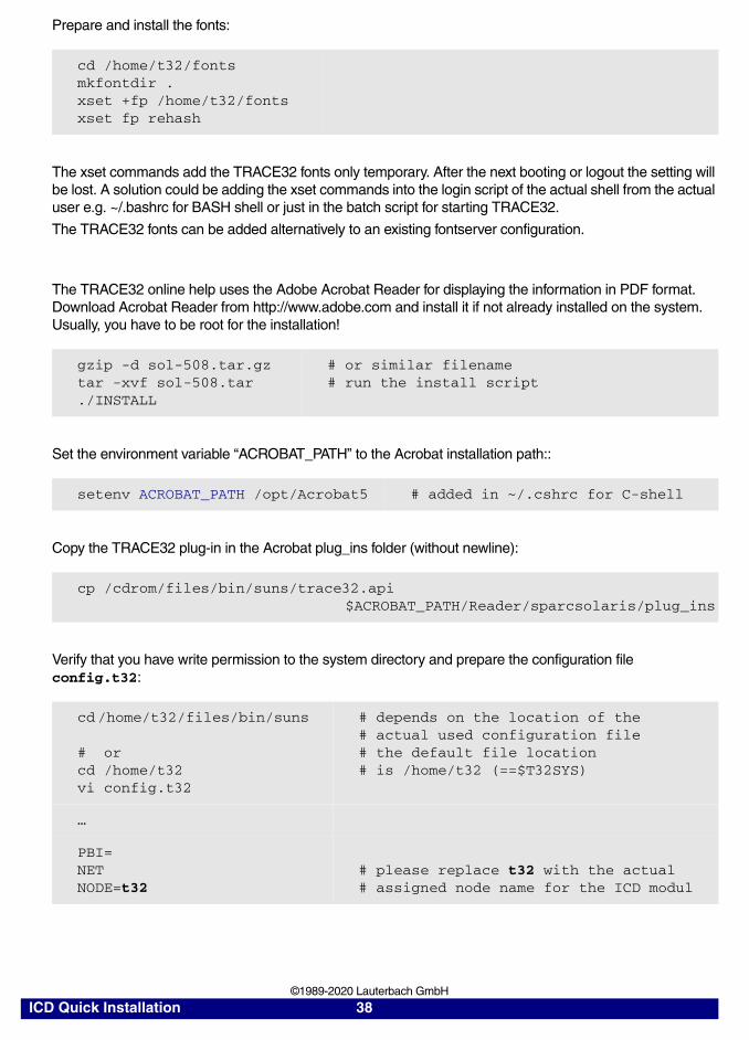
Prepare and install the fonts:
The xset commands add the TRACE32 fonts only temporary. After the next booting or logout the setting will be lost. A solution could be adding the xset commands into the login script of the actual shell from the actual user e.g. ~/.bashrc for BASH shell or just in the batch script for starting TRACE32.
The TRACE32 fonts can be added alternatively to an existing fontserver configuration.
The TRACE32 online help uses the Adobe Acrobat Reader for displaying the information in PDF format. Download Acrobat Reader from http://www.adobe.com and install it if not already installed on the system. Usually, you have to be root for the installation!
Set the environment variable “ACROBAT_PATH” to the Acrobat installation path::
Copy the TRACE32 plug-in in the Acrobat plug_ins folder (without newline):
Verify that you have write permission to the system directory and prepare the configuration file config.t32:
cd /home/t32/fontsmkfontdir .xset +fp /home/t32/fontsxset fp rehash
gzip -d sol-508.tar.gztar -xvf sol-508.tar./INSTALL
# or similar filename# run the install script
setenv ACROBAT_PATH /opt/Acrobat5 # added in ~/.cshrc for C-shell
cp /cdrom/files/bin/suns/trace32.api $ACROBAT_PATH/Reader/sparcsolaris/plug_ins
cd /home/t32/files/bin/suns
# orcd /home/t32vi config.t32
# depends on the location of the# actual used configuration file # the default file location# is /home/t32 (==$T32SYS)
…
PBI=NET NODE=t32
# please replace t32 with the actual# assigned node name for the ICD modul
ICD Quick Installation 38 ©1989-2020 Lauterbach GmbH
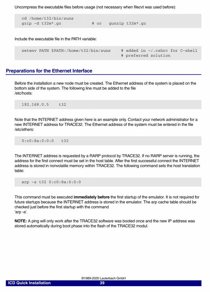
Uncompress the executable files before usage (not necessary when filecvt was used before):
Include the executable file in the PATH variable:
Preparations for the Ethernet Interface
Before the installation a new node must be created. The Ethernet address of the system is placed on the bottom side of the system. The following line must be added to the file /etc/hosts:
Note that the INTERNET address given here is an example only. Contact your network administrator for a new INTERNET address for TRACE32. The Ethernet address of the system must be entered in the file /etc/ethers:
The INTERNET address is requested by a RARP protocol by TRACE32. If no RARP server is running, the address for the first connect must be set in the host table. After the first successful connect the INTERNET address is stored in nonvolatile memory within TRACE32. The following command sets the host translation table:
This command must be executed immediately before the first startup of the emulator. It is not required for future startups because the INTERNET address is stored in the emulator. The arp cache table should be checked just before the first startup with the command 'arp -a'.
NOTE: A ping will only work after the TRACE32 software was booted once and the new IP address was stored automatically during boot phase into the flash of the TRACE32 modul.
cd /home/t32/bin/sunsgzip -d t32m*.gz # or gunzip t32m*.gz
setenv PATH $PATH:/home/t32/bin/suns # added in ~/.cshrc for C-shell# preferred solution
192.168.0.5 t32
0:c0:8a:0:0:0 t32
arp -s t32 0:c0:8a:0:0:0
ICD Quick Installation 39 ©1989-2020 Lauterbach GmbH
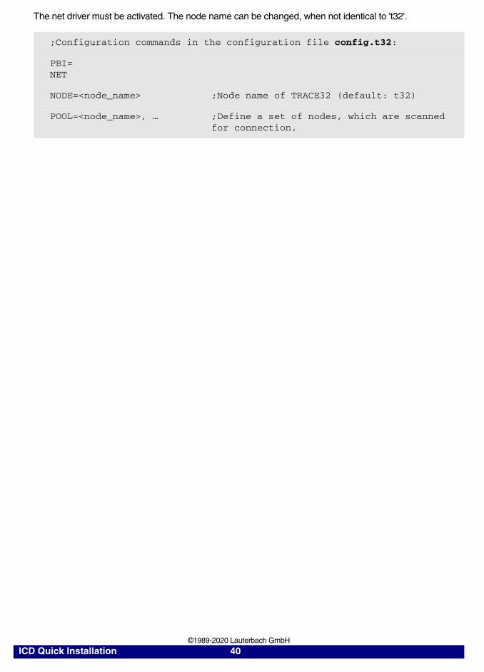
The net driver must be activated. The node name can be changed, when not identical to 't32'.
;Configuration commands in the configuration file config.t32:
PBI=NET
NODE=<node_name> ;Node name of TRACE32 (default: t32)
POOL=<node_name>, … ;Define a set of nodes, which are scanned for connection.
ICD Quick Installation 40 ©1989-2020 Lauterbach GmbH
Troubleshooting
If you can not solve your problem with the following hints contact our support line:
telephone: ++49 8102/9876-555facsimile: ++49 8102/9876-999e-mail: [email protected]
System doesn't response to ping on Ethernet
Internet address already setup in system, or arp used?
When arp is used, it must be used on the same workstation short before.
Ethernet address correct?
System on the correct subnet?
Cables and transceiver o.k.?
Ethernet software in host (PC) configured correctly?
xset +fp fontpath gives error 'bad value …'
Does the font directory exist?
Does the fonts.dir file exist (created by mkfontdir)?
Is the directory seen under the same name by the X-server?
Have all directories that lead to the font directory read and execute
permissions for everybody?
Executable program does not start or gives fatal error
When transferring between different OS-systems, files copied in binary mode?
Access rights to file in directory o.k.?
Configuration file contents o.k.?
Executable program displays 'FATAL ERROR selecting device-driver …
Using configuration file for MS-DOS for the WINDOWS-Driver?
WINDOWS and workstation drivers cannot load new drivers.
Environment variable 'T32CONFIG' and/or 'T32SYS' correctly set?
Executable program displays 'error reading config.t32:'
Configuration file contents o.k.?
Commands in file in uppercase?
Blanks inserted/not inserted?
Device specific commands placed after device header?
Device configuration blocks separated by empty lines?
Environment variable 'T32CONFIG' and/or 'T32SYS' correctly set?
Executable program stops without message, but with window opened
Access rights to directory o.k.?
On UNIX host, try with 'NOLOCK' feature.
When using the RS232 interface: Is a login process active on the tty?
ICD Quick Installation 41 ©1989-2020 Lauterbach GmbH
Program stops with message 'font xxxx not found'
Do fonts appear in the 'xlsfonts' command?
Can one font (e.g. t32-lsys-16) be displayed by 'xfd -fn t32-lsys-16'?
Fonts added to X-Windows FONTPATH?
Fonts converted, when required, and .bdf files removed?
Command to generate font directory executed with correct parameters?
Fonts installed on the X-Windows server, not client?
If using an X-Terminal, use the conversion programs for the X-Terminal?
Executable program displays 'boot.t32 not found'
Access rights to directory o.k.?
Read and write access to boot.t32 (write required on UNIX without NOLOCK)?
Configuration file contents o.k.?
Environment variable 'T32SYS' correctly set?
ICD Quick Installation 42 ©1989-2020 Lauterbach GmbH
Executable program stops after displaying 'error reading boot.t32'
When transferring between different OS-systems, files copied in binary mode?
Access rights granted?
Try again after switching off the TRACE32 system?
Executable program stops after displaying 'booting …' or 'finished.'
When transferring between different OS-systems, files copied in binary mode?
Packet size set correctly on Ethernet, handshake set when required?
Bootloader stops with message “fatal error …'”
When transferring between different OS-systems, files copied in binary mode?
Mixing different versions of the software, e.g. MCC.T32 and MCCxxx.t32?
Bootloader displays “cannot save image …”
Write access right on system directory?
Disk full?
Existing read-only file?
Software crashes or stops after booting is finished
Boot image file maybe destroyed, remove all boot0x.t32 files?
Connection of modules o.k., connector bend?
Software doesn't work stable
Boot image file maybe destroyed, remove all boot0x.t32 files?
Connection of modules o.k., connector bend?
Check connection of Fibre Optic, Ethernet or Parallel interface.
On Ethernet try with smaller packet size and/or handshake.
Emulation system doesn't work correctly
Check Emulation Probe Manual in “Targets” part of the manual.
ICD Quick Installation 43 ©1989-2020 Lauterbach GmbH

Parallel Port not working stable
Check that the port is on the correct mode. Choose either EPP 1.9 or compatible mode. The mode selection can usually be done in the BIOS setup (can be activated during booting).
USB debugger not detected at all by LINUX
There are a few reasons why this can happen:
• the running kernel does not support USB yet
• USB not enabled during kernel configuration
• USB enabled as modules in the kernel configuration, but module autoload did fail or isn't configured
• usbdevfs is not mounted
• usbdevfs is mounted, but not at /proc/bus/usb
• bad USB cable, use the original one or make sure it is at max. 3 meters longcable type lettering: 28AWG/1PR 24AWG/2C
• old debugger firmware - version V6.5 or later needed
Menu or softkey text is displayed wrong under LINUX
On systems which use a mixed set of 8bit and 16bit menu fonts, and have only *-iso10646-* system fonts installed, no meaningful glyphs are rendered in the menu or softkeys of TRACE32 main window.
If this happens, please install the additional iso8859 system font package(s).e.g. yum install xorg-x11-fonts-ISO8859-1-75dpi
Fixed width font t32sys not found under WINDOWS
When you start the TRACE32 executable the fonts are loaded. If a SW update will be done, which replaces the TRACE32 font file named t32font.fon, the new fonts will not be activated as long as the old fonts are loaded.
This happens even if both font files are identical.
Please reboot your Windows PC to solve this issue.
FAQ
Please refer to our Frequently Asked Questions page on the Lauterbach website.
ICD Quick Installation 44 ©1989-2020 Lauterbach GmbH
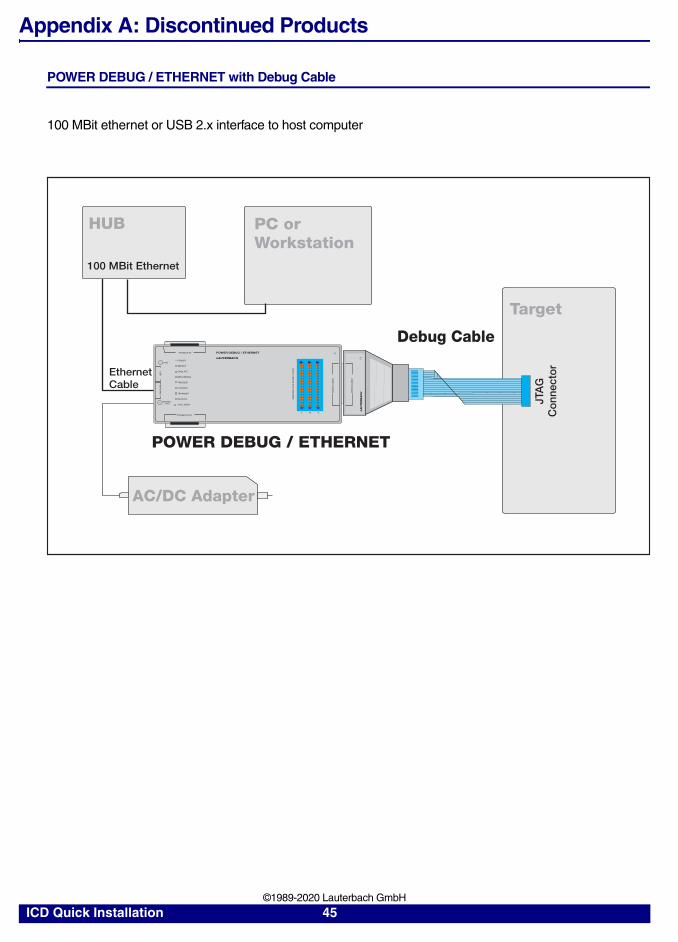
Appendix A: Discontinued Products
POWER DEBUG / ETHERNET with Debug Cable
100 MBit ethernet or USB 2.x interface to host computer
POWER DEBUG / ETHERNETPODBUS IN
TRIG
POWER7-9 V
US
B
LAUTERBACH
PODBUS OUT
DE
BU
G C
AB
LE
Target
PC orWorkstation
EthernetCable
POWER
SELECT
EMULATE
RECORDING
TRIGGER
ET
HE
RN
ET
CON ERR
TRANSMIT
RECEIVE
COLLISION
HUB
100 MBit Ethernet
Debug Cable
JTA
GC
onne
ctor
DE
BU
G C
AB
LE
LA
UT
ER
BA
CH
RE
SE
RV
ED
FO
R P
OW
ER
TR
AC
E
C B A
POWER DEBUG / ETHERNET
AC/DC Adapter
ICD Quick Installation 45 ©1989-2020 Lauterbach GmbH

POWER DEBUG II with Debug Cable
GBit ethernet or USB 2.x interface to host computer
POWER DEBUG IIPODBUS SYNC
TRIG
POWER7-9 V
US
B
LAUTERBACHPODBUS OUT
DE
BU
G C
AB
LE
Target
POWER DEBUG II
EthernetCable
POWER
SELECT
RUNNING
LINK
ACTIVITY
ET
HE
RN
ET
HUB
1 GBit Ethernet
Debug Cable
DE
BU
G C
AB
LE
JTA
GC
onn
ecto
r
LA
UT
ER
BA
CH
PODBUS EXPRESS OUT
PC orWorkstation
AC/DC Adapter
ICD Quick Installation 46 ©1989-2020 Lauterbach GmbH
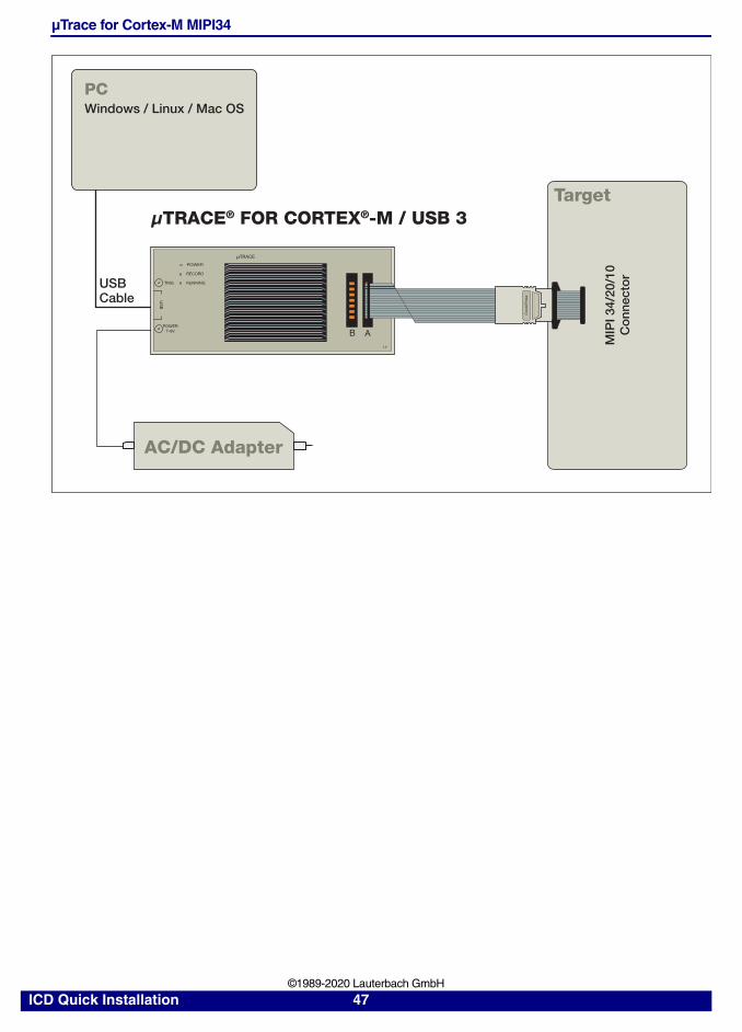
µTrace for Cortex-M MIPI34
Target
USBCable
AC/DC Adapter
μTRACE® FOR CORTEX®-M / USB 3
TRIG
POWER7-9V
POWER
RECORD
RUNNING
μTRACE
B A
US
B
PCWindows / Linux / Mac OS
MIP
I 34/
20/1
0C
onn
ecto
r
Com
biP
rob
e
ICD Quick Installation 47 ©1989-2020 Lauterbach GmbH
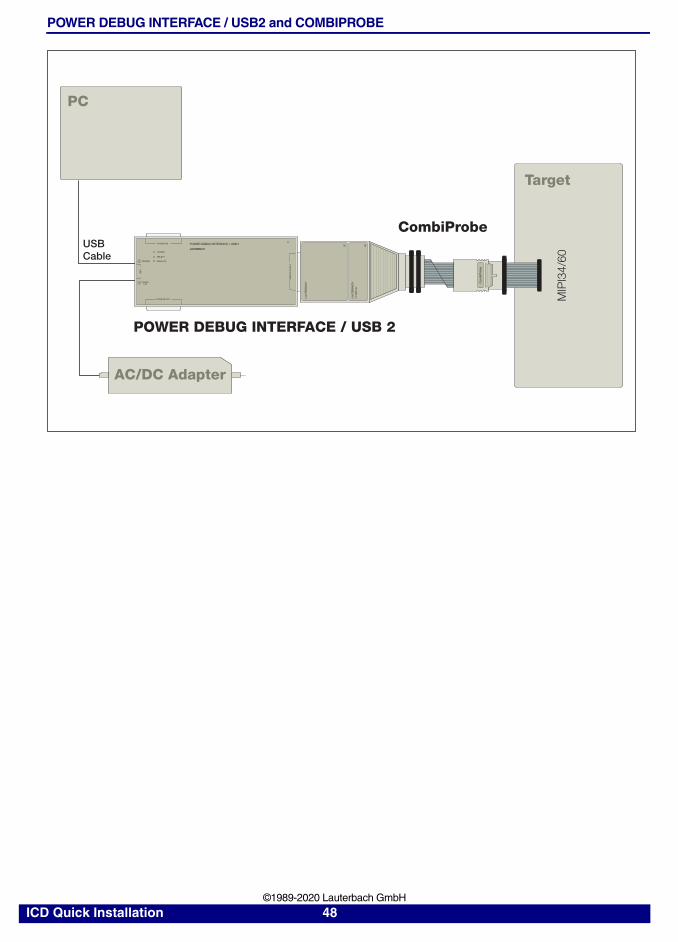
POWER DEBUG INTERFACE / USB2 and COMBIPROBE
MIPI34/60
Target
CombiProbe
POWER DEBUG INTERFACE / USB 2
AC/DC Adapter
PC
LAU
TER
BA
CH
LAU
TER
BA
CH
Com
biP
rob
e
Com
biP
rob
e
PODBUS IN
POWER
SELECT
EMULATETRIGGER
POWER7-9V
LAUTERBACH
PODBUS OUT
DE
BU
G C
AB
LE
US
B
POWER DEBUG INTERFACE / USB 2USBCable
ICD Quick Installation 48 ©1989-2020 Lauterbach GmbH
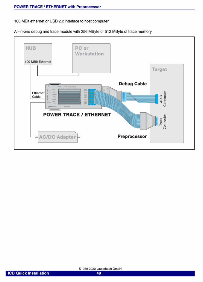
POWER TRACE / ETHERNET with Preprocessor
100 MBit ethernet or USB 2.x interface to host computer
All-in-one debug and trace module with 256 MByte or 512 MByte of trace memory
POWER TRACE / ETHERNETPODBUS IN
TRIG
POWER7-9 V
US
B
LAUTERBACHPODBUS OUT
DE
BU
G C
AB
LE
Target
AC/DC Adapter
PC orWorkstation
POWER TRACE / ETHERNET
EthernetCable
POWER
SELECT
EMULATE
RECORDING
TRIGGER
ET
HE
RN
ET
CON ERR
TRANSMIT
RECEIVE
COLLISION
HUB
100 MBit Ethernet
Debug Cable
JTA
GC
onn
ecto
r
DE
BU
G C
AB
LE
LA
UT
ER
BA
CH
LO
GIC
AN
ALY
ZE
R P
RO
BE
C B A
Trac
eC
onn
ecto
r
Preprocessor
ICD Quick Installation 49 ©1989-2020 Lauterbach GmbH
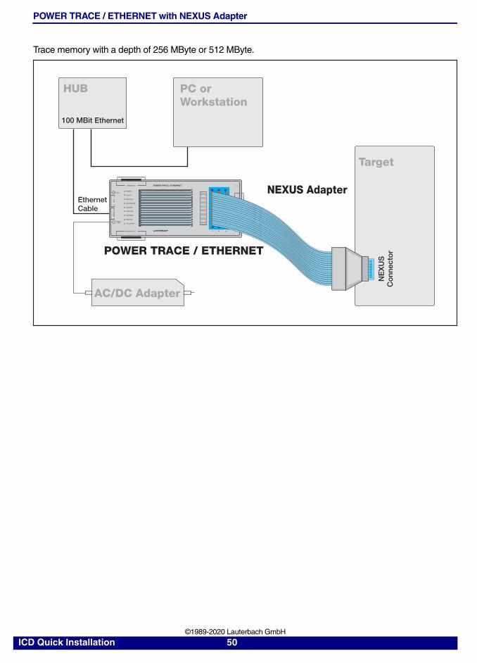
POWER TRACE / ETHERNET with NEXUS Adapter
Trace memory with a depth of 256 MByte or 512 MByte.
POWER TRACE / ETHERNETPODBUS IN
TRIG
POWER7-9 V
US
B
LAUTERBACHPODBUS OUT
DE
BU
G C
AB
LE
Target
POWER TRACE / ETHERNET
EthernetCable
POWER
SELECT
EMULATE
RECORDING
TRIGGER
ET
HE
RN
ET
CON ERR
TRANSMIT
RECEIVE
COLLISION
C B A
HUB
100 MBit Ethernet
NEXUS Adapter
NE
XU
SC
onn
ecto
r
LO
GIC
AN
ALY
ZE
R P
RO
BE
AC/DC Adapter
PC orWorkstation
ICD Quick Installation 50 ©1989-2020 Lauterbach GmbH
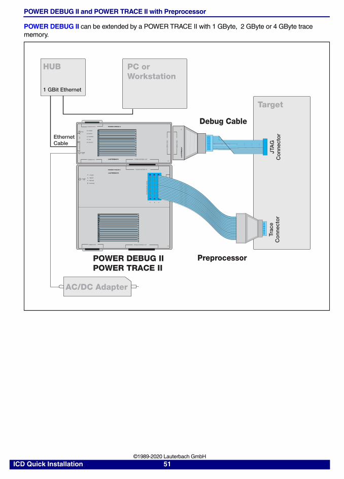
POWER DEBUG II and POWER TRACE II with Preprocessor
POWER DEBUG II can be extended by a POWER TRACE II with 1 GByte, 2 GByte or 4 GByte trace memory.
POWER TRACE II
POWER
SELECT
RECORD
RUNNING
POWER7-9V
LAUTERBACH
PODBUS OUT
POWER DEBUG IIPODBUS SYNC
TRIG
POWER7-9 V
US
B
LAUTERBACHPODBUS OUT
DE
BU
G C
AB
LE
Target
POWER DEBUG IIPOWER TRACE II
EthernetCable
POWER
SELECT
RUNNING
LINK
ACTIVITY
ET
HE
RN
ET
HUB
1 GBit Ethernet
Debug Cable
JTA
GC
onn
ecto
r
DE
BU
G C
AB
LE
LA
UT
ER
BA
CH
LO
GIC
AN
ALY
ZE
R P
RO
BE
C B A
Trac
eC
onn
ecto
r
Preprocessor
PODBUS EXPRESS OUT
PODBUS EXPRESS IN
PODBUS EXPRESS OUT
PR
EP
RO
CE
SS
OR
/ N
EX
US
PC orWorkstation
AC/DC Adapter
ICD Quick Installation 51 ©1989-2020 Lauterbach GmbH
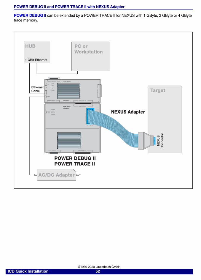
POWER DEBUG II and POWER TRACE II with NEXUS Adapter
POWER DEBUG II can be extended by a POWER TRACE II for NEXUS with 1 GByte, 2 GByte or 4 GByte trace memory.
POWER TRACE II
POWER
SELECT
RECORD
RUNNING
POWER7-9V
LAUTERBACH
PODBUS OUT
POWER DEBUG IIPODBUS SYNC
TRIG
POWER7-9 V
US
B
LAUTERBACHPODBUS OUT
DE
BU
G C
AB
LE Target
POWER DEBUG IIPOWER TRACE II
EthernetCable
POWER
SELECT
RUNNING
LINK
ACTIVITY
ET
HE
RN
ET
HUB
1 GBit Ethernet
LO
GIC
AN
ALY
ZE
R P
RO
BE
C B A
PODBUS EXPRESS OUT
PODBUS EXPRESS IN
PODBUS EXPRESS OUT
PR
EP
RO
CE
SS
OR
/ N
EX
US
PC orWorkstation
AC/DC Adapter
NE
XU
SC
onn
ecto
r
NEXUS Adapter
ICD Quick Installation 52 ©1989-2020 Lauterbach GmbH
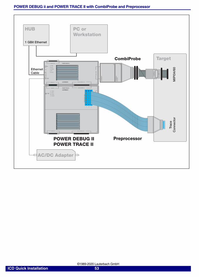
POWER DEBUG ii and POWER TRACE II with CombiProbe and Preprocessor
POWER TRACE IIPODBUS IN
POWER
SELECT
RECORD
RUNNING
POWER7-9V
LAUTERBACH
PODBUS OUT
POWER DEBUG IIPODBUS SYNC
TRIG
POWER7-9 V
US
B
LAUTERBACHPODBUS OUT
DE
BU
G C
AB
LE
Target
POWER DEBUG IIPOWER TRACE II
EthernetCable
POWER
SELECT
RUNNING
LINK
ACTIVITY
ET
HE
RN
ET
HUB
1 GBit Ethernet
LO
GIC
AN
ALY
ZE
R P
RO
BE
C B A
Trac
eC
onn
ecto
rM
IPI3
4/60
Preprocessor
PODBUS EXPRESS OUT
PODBUS EXPRESS IN
PODBUS EXPRESS OUT
PR
EP
RO
CE
SS
OR
/ N
EX
US
PC orWorkstation
AC/DC Adapter
CombiProbe
LAU
TER
BA
CH
LAU
TER
BA
CH
Com
biP
rob
e
Com
biP
rob
e
ICD Quick Installation 53 ©1989-2020 Lauterbach GmbH

POWER DEBUG II and POWER TRACE II and POWER INTEGRATOR II
POWER DEBUG II can be extended by a POWER TRACE II with 1 GByte, 2 GByte or 4 GByte trace memory, and a POWER INTEGRATOR II Logic Analyzer with a 1 GByte, 2 GByte or 4 GByte logic analyzer memory.
Target
JTA
GC
onn
ecto
rLo
gic
Ana
lyze
rC
onn
ecto
rT
race
Co
nnec
tor
POWER DEBUG II
TRIGGERTRIGGER
US
B
DE
BU
G C
AB
LE
ETH
ER
NE
T
LA
UT
ER
BA
CH
POWER7-9 V
DE
BU
G C
AB
LE
PODBUS SYNC
PODBUS OUT
POWER
SELECT
RUNNING
LINK
ACTIVITY
PODBUS EXPRESS OUTLAUTERBACH
POWER7-9 V
PODBUS OUT PODBUS EXPRESS OUT
POWER
SELECT
RECORD
RUNNING
PODBUS EXPRESS IN
POWER TRACE II
LAUTERBACH
C B A
PR
EP
RO
CE
SS
OR
/ N
EX
US
POWER DEBUG IIPOWER TRACE IIPOWER INTEGRATOR II
EthernetCable
Debug Cable
Preprocessor
POWER7-9 V
TRIG
GE
R O
UT
PODBUS OUT
PA
TTER
N O
UT
PODBUS EXPRESS OUT
POWER
SELECT
RECORD
RUNNING
PODBUS EXPRESS IN
A B C D E F
POWER INTEGRATOR II
LAUTERBACH
AC/DC Adapter
AC/DC Adapter
HUB PC orWorkstation
1 GBit Ethernet
LOG
IC A
NA
LYZ
ER
PR
OB
E
ICD Quick Installation 54 ©1989-2020 Lauterbach GmbH
NOTE: • For the first two devices, only one AC/DC adapter is required. Each additional device requires an additional AC/DC adapter.
• An additional device in a PODBUS device chain cannot be damaged if it is not connected to its required AC/DC adapter.
• In case of a missing AC/DC adapter, an error message is displayed in the AREA window. To view the error message, choose View menu > Message Area.Or type AREA at the TRACE32 command line.
ICD Quick Installation 55 ©1989-2020 Lauterbach GmbH
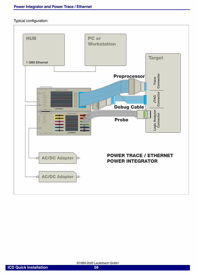
Power Integrator and Power Trace / Ethernet
Typical configuration:
Target
POWER TRACE / ETHERNETPODBUS IN
TRIGGER
US
B
LAUTERBACHPODBUS OUT
DE
BU
G C
AB
LE
POWER
SELECT
EMULATE
RECORDING
TRIGGER
ETH
ER
NE
T
CON ERR
TRANSMIT
RECEIVE
COLLISION
LA
UTE
RB
AC
H
C B A
POWER INTEGRATORPODBUS IN
POWER7-9 V
LAUTERBACHPODBUS OUT
POWER
SELECT
TRACE
TRIGGER
ERROR
TR
IGG
ER
OU
T
A
B
C
D
E
F
J
K
L
N
M
O
POWER7-9V
DE
BU
G C
AB
LE
AC/DC Adapter
AC/DC Adapter
HUB PC orWorkstation
1 GBit Ethernet
POWER TRACE / ETHERNETPOWER INTEGRATOR
Debug Cable
Probe
Preprocessor
JTA
GC
onn
ecto
rLo
gic
Ana
lyze
rC
onn
ecto
rT
race
Co
nnec
tor
ICD Quick Installation 56 ©1989-2020 Lauterbach GmbH