IBM i: Token ring · Related concepts: “Configuring token-ring support” on page 9 After...
54
IBM i Version 7.2 Networking Token ring IBM
Transcript of IBM i: Token ring · Related concepts: “Configuring token-ring support” on page 9 After...
IBM iVersion 7.2
NetworkingToken ring
IBM

IBM iVersion 7.2
NetworkingToken ring
IBM

NoteBefore using this information and the product it supports, read the information in “Notices” on page 43.
This document may contain references to Licensed Internal Code. Licensed Internal Code is Machine Code and islicensed to you under the terms of the IBM License Agreement for Machine Code.
© Copyright IBM Corporation 1998, 2013.US Government Users Restricted Rights – Use, duplication or disclosure restricted by GSA ADP Schedule Contractwith IBM Corp.
Contents
Token ring. . . . . . . . . . . . . . 1PDF file for Token ring . . . . . . . . . . . 1Token-ring overview. . . . . . . . . . . . 1
Supported token-ring functions . . . . . . . 2Connection establishment between LAN devices . 2
How LAN devices identify themselves . . . 3SNA exchange identifiers . . . . . . . 3
Which LAN device initiates the connection . . 4Dial mode (SNA) . . . . . . . . . . 4Answer mode (SNA) . . . . . . . . 5
SNA connections to LAN protocols . . . . . . 5Your SNA service access points . . . . . . 6
Maximum frame size of token ring . . . . . . 7Planning for token-ring support . . . . . . . . 7
Maximum LAN frame size . . . . . . . . 8LAN IOA addresses . . . . . . . . . . . 8
Configuring token-ring support . . . . . . . . 9Configuring TCP/IP over token ring . . . . . 9Configuring SNA over token ring . . . . . . 9
Creating the token-ring line description . . . 10Token-ring IOAs. . . . . . . . . . 12Selecting a LAN IOA . . . . . . . . 12
Creating the SNA controller description . . . 12Creating the SNA device description . . . . 14
Examples: Configuring SNA over token ring . . 15Example: Connecting a system to anothersystem . . . . . . . . . . . . . . 16Example: Connecting the system to itself . . 17Example: Connecting a system to a 3745 host 17
Example: Creating a host physicalconfiguration . . . . . . . . . . . 18Example: Creating a host logicalconfiguration . . . . . . . . . . . 19
Example: Connecting a system to a 3174Model 1L gateway . . . . . . . . . . 20
Example: Creating the NCP generation fora 3174 gateway . . . . . . . . . . 20Example: Connecting a system to a 3174subsystem control unit. . . . . . . . 21
Example: Creating parallel connections to ahost . . . . . . . . . . . . . . . 21
Example: Configuring the physical andlogical parallel connections on the hostsystem . . . . . . . . . . . . . 22
Managing token-ring support . . . . . . . . 24Changing the line descriptions to use token ring 24Assigning the token-ring line description to aTCP/IP interface . . . . . . . . . . . 26Enabling objects to accept connections . . . . 27Viewing the address of your LAN IOA . . . . 28Configuration object commands . . . . . . 28
Tuning token-ring performance . . . . . . . . 29Adjusting your LAN-frame size . . . . . . 29
Viewing the QSYSOPR message queue orother message queues . . . . . . . . . 30Bridges dropping frames . . . . . . . . 30Token-ring line description commands . . . 30
Timing . . . . . . . . . . . . . . . 31Timing parameters . . . . . . . . . . 31
The LANCNNTMR and LANCNNRTYparameters . . . . . . . . . . . 32The LANRSPTMR and LANFRMRTYparameters . . . . . . . . . . . 32The LANACKTMR and LANACKFRQparameters . . . . . . . . . . . 33The LANINACTMR parameter . . . . . 34The LANMAXOUT parameter . . . . . 34The LANWDWSTP parameter . . . . . 35The LANACCPTY parameter . . . . . 36
Changing timing parameters . . . . . . 36Troubleshooting token ring . . . . . . . . . 37
Troubleshooting LANs. . . . . . . . . . 37Why some LAN connections fail . . . . . . 37Why PCs do not connect to your system . . . 38Understanding the token-ring address format . . 39
Notices . . . . . . . . . . . . . . 43Programming interface information . . . . . . 45Trademarks . . . . . . . . . . . . . . 45Terms and conditions . . . . . . . . . . . 45
© Copyright IBM Corp. 1998, 2013 iii

iv IBM i: Token ring
Token ring
This topic collection can help you plan, configure, manage, tune, and troubleshoot token-ring support forTCP/IP and Systems Network Architecture (SNA).
Existing installations:
Users who have existing token-ring line descriptions can change them to take advantage of the 100 Mbpscard. If you use the line description with TCP/IP, you must also assign it to a TCP/IP interface.
Note: By using the code examples, you agree to the terms of the “Code license and disclaimerinformation” on page 40.Related tasks:“Changing the line descriptions to use token ring” on page 24To use an existing token-ring line description with System i® Navigator, you must first change the valuesfor these fields.“Assigning the token-ring line description to a TCP/IP interface” on page 26You can assign the token-ring line description to a new or an existing TCP/IP interface through System iNavigator.
PDF file for Token ringYou can view and print a PDF file of this information.
To view or download the PDF version of this document, select Token ring (about 590 KB).
Saving PDF files
To save a PDF on your workstation for viewing or printing:1. Right-click the PDF link in your browser.2. Click the option that saves the PDF locally.3. Navigate to the directory in which you want to save the PDF.4. Click Save.
Downloading Adobe Reader
You need Adobe Reader installed on your system to view or print these PDFs. You can download a free
copy from the Adobe Web site (www.adobe.com/products/acrobat/readstep.html) .
Token-ring overviewBefore you configure the system, you need to know what token-ring functions are supported by yoursystem, what determines a successful connection between local area network (LAN) devices, whatconnects Systems Network Architecture (SNA) to token ring, and what determines your maximum framesize of token ring.
Verify that your system enclosure supports your token-ring input/output adapter (IOA). To access thePCI adapter information that is documented in the IBM® Systems Hardware Information Center, followthis navigation path: IBM Systems Hardware Information > Installing hardware > Installing featuresand replacing parts > Select instructions by feature or part name > PCI adapter.
© Copyright IBM Corp. 1998, 2013 1
Related concepts:“Configuring token-ring support” on page 9After understanding and planning your token-ring support, you are ready to configure token ring on thesystem.
Supported token-ring functionsA range of token-ring technologies that support speeds of 4 Mbps, 16 Mbps, and 100 Mbps are supportedon the system.
These token-ring technologies support the IEEE 802.5 standard. The 100 Mbps token-ring input/outputadapter (IOA) supports the High-Speed Token-Ring IEEE 802.5 standard. This standard specifies 100Mbps operation.
The 100 Mbps token ring IOA:
Your system can use the Peripheral Component Interconnect (PCI) 100/16/4 Mbps Token-Ring Adapterto support faster networking. The IOA supports many protocols including TCP/IP and Systems NetworkArchitecture (SNA). It is compatible with earlier devices, but does not support token-pipes or multilink.The adapter is also known as the 2744 IOA. The functions that the IOA introduces are as follows:v Automatic ring-speed sensing (automatic sense) enables your system and the switch to find the
highest common ring speed to use between them. The destination does not need to match this speed,because the switch manages the differences in speed.
v Duplex mode negotiation enables your system and the switch to agree on the duplex mode to use(half or full duplex). The available duplexing modes are dependent on the ring speed that you use. At4 Mbps or 16 Mbps, you can use either half-duplex or full-duplex mode. At 100 Mbps, you must usefull-duplex mode (the speed for each transmitting or receiving channel is 100 Mbps).
Early token release:
Only 16 Mbps rings that use half-duplex mode can use the early token release function. This functionreduces the time that the next device on the same ring waits for a free token. Early token release enablesthe transmitting device to release the free token right after sending a frame. Thus, the next devicereceives the free token sooner and can thereby transmit a frame. This function is beneficial only in ringswhere the time to transmit a frame is shorter than the travel time of the frame.
Connection establishment between LAN devicesIf you use Systems Network Architecture (SNA) with a LAN protocol, follow these instructions toestablish a connection between the LAN devices.
The correct relationship between a line description and a controller description helps to ensure connectionestablishment. A controller description determines which line descriptions your system uses. Therefore,you must ensure that the controller description refers to the correct line description.
Also, a line description controls the number of active controllers that can access it. By making the numbertoo small, you might stop the controller description from accessing the line description. Therefore, youmust ensure a value that is large enough to allow the controller description to access the line description.
Besides the correct relationship between the line description and the controller description, thedescriptions must also contain the correct information to ensure connection establishment.Related concepts:“Why some LAN connections fail” on page 37Connection failures might be caused by various reasons. Sometimes an incorrectly configured controllerdescription can cause a connection failure.
2 IBM i: Token ring
Related tasks:“Creating the token-ring line description” on page 10You can use the Create Line Description (CRTLINTRN) command to create a token-ring line description.“Creating the SNA controller description” on page 12The controller description indicates the remote devices to which the system connects.
How LAN devices identify themselvesDuring the connection process, your system and the remote device exchange information with each otherto ensure connection to the correct system and device.
Your system sends information to the remote device, which the device uses to ensure the connection tothe correct system. The remote device also sends information to your system, which your system uses toensure the connection to the correct device. If the exchanged information matches the information that iscontained in the line and controller descriptions, and the other connection values are also correct, theconnection process continues. Likewise, the remote device performs a similar process.
Your system and the remote device use two verifications during the connection process to ensureconnection to the correct device. One verification (required), matches the line description information andthe controller description information with the connection information that the remote device sent. If amatch occurs, your system continues with the connection process.
This list shows the information that the remote device sends:v The address associated with the input/output adapter (IOA) on the remote device. This address is
either the preset address or the locally administered address.v The source service access point (SSAP) on the remote device.v The destination service access point (DSAP).
The other verification matches the exchange identifier values. For Advanced Program-to-ProgramCommunication (APPC), this verification is optional. Systems Network Architecture (SNA) hosts that useparallel connections require this verification.Related concepts:“SNA connections to LAN protocols” on page 5Systems Network Architecture (SNA) can be connected to a LAN protocol by using one or more serviceaccess points (SAPs).“Why some LAN connections fail” on page 37Connection failures might be caused by various reasons. Sometimes an incorrectly configured controllerdescription can cause a connection failure. Related tasks:“Creating the SNA controller description” on page 12The controller description indicates the remote devices to which the system connects.
SNA exchange identifiers:
To establish a connection, your system and the remote device exchange information that includes theexchange identification (XID).
Systems Network Architecture (SNA) hosts that use parallel connections require the XIDs. You define theXIDs in the controller description. Typically, during the connection process, your system conducts aninitial poll with NULL XIDs to determine whether the remote device is active or not. If the remote devicedoes not respond to the poll within the specified time period, your system can send another XID to thedevice. If the remote device responds to the poll, your system and the remote device exchange XIDs andestablish the link.
Token ring 3
The controller description for SNA hosts names the XID value as the local exchange identifier. TheAdvanced Program-to-Program Communication (APPC) controller description names the XID value asthe exchange identifier.Related tasks:“Creating the SNA controller description” on page 12The controller description indicates the remote devices to which the system connects.
Which LAN device initiates the connectionIn a Systems Network Architecture (SNA) environment, you can determine who initiates the connectionrequest and who waits for an incoming connection request.
To have your system initiate the connection, configure the controller description to dial the destination. Ifno connection is established, your controller description switches to answer mode (where it waits for adevice to dial into your system).
To have your system wait for incoming calls, configure the controller description to answer the incomingcalls. You use the dial mode to make connection requests and use the answer mode to have the systemwait for incoming connection requests. You specify one of these modes through the Initial connection(INLCNN) field of the controller description.Related concepts:“Why some LAN connections fail” on page 37Connection failures might be caused by various reasons. Sometimes an incorrectly configured controllerdescription can cause a connection failure. Related tasks:“Creating the SNA controller description” on page 12The controller description indicates the remote devices to which the system connects.
Dial mode (SNA):
To send a connection request to a remote device, use the dial mode, which is used by Systems NetworkArchitecture (SNA) controller descriptions.
Dial mode starts when you vary on the controller description. During the dialing process, the systempolls the remote device to determine if the device is ready to transmit. If the remote device is ready, theconnection process continues. Successful connection is still possible even if the local and remote devicesdial each other simultaneously.
These controller description fields control the frequency and duration of the polling:v The LAN connection retry (LANCNNRTY) parameter determines the number of times your system
polls the remote device.v The LAN connection timer (LANCNNTMR) parameter determines the length of time between each
poll.
If the remote device answers the poll within the time that these parameters specify, your system proceedswith establishing the connection. If not, your system sends an inquiry message (CPA58E0 or CPA57EF) tothe system operator message queue. This message indicates that a connection attempt failed and that thecontroller description is now in the answer mode.Related concepts:“The LANCNNTMR and LANCNNRTY parameters” on page 32Your Systems Network Architecture (SNA) controller description has two parameters: LAN connectiontimer (LANCNNTMR) and LAN connection retry (LANCNNRTY). They work together to define thefrequency and persistence of polling the remote station to establish a connection.
4 IBM i: Token ring
“Answer mode (SNA)”If you specify the answer mode, the input/output adapter (IOA) cannot send connection requests, butcan respond to incoming connection requests.Related tasks:“Creating the SNA controller description” on page 12The controller description indicates the remote devices to which the system connects.“Creating the SNA device description” on page 14The device description describes the communications device used by the remote device.
Answer mode (SNA):
If you specify the answer mode, the input/output adapter (IOA) cannot send connection requests, butcan respond to incoming connection requests.
Systems with controller descriptions that are configured with dial mode send the connection requests.The controller description must be varied on before the system can respond to a connection request.Related concepts:“Dial mode (SNA)” on page 4To send a connection request to a remote device, use the dial mode, which is used by Systems NetworkArchitecture (SNA) controller descriptions.Related tasks:“Creating the SNA controller description” on page 12The controller description indicates the remote devices to which the system connects.“Creating the SNA device description” on page 14The device description describes the communications device used by the remote device.
SNA connections to LAN protocolsSystems Network Architecture (SNA) can be connected to a LAN protocol by using one or more serviceaccess points (SAPs).
Multiple SAPs allow you to have multiple connections between SNA and a LAN protocol, thuspermitting multiple communication paths between independent applications.
You or the system specifies the SAPs to use in the line and controller descriptions. For SNA, the systemcan automatically create one SAP value (the default value). There might be cases where you want tochange this value or have additional SAPs:v The remote system does not use the default source service access point (SSAP).v You want parallel station-to-station connections between adapters. This might be what you want if you
link two applications that require different controller descriptions.v You want station-to-station connections to the same adapters. You might want to do this to configure
multiple SAPs to test an application on a single system.
SSAP and DSAP:
Local SAPs are known as source service access points (SSAPs). The remote SAPs are known asdestination service access points (DSAPs). Your system sends data from a SSAP to a DSAP.Related concepts:“How LAN devices identify themselves” on page 3During the connection process, your system and the remote device exchange information with each otherto ensure connection to the correct system and device.“Your SNA service access points” on page 6To change the default Systems Network Architecture (SNA) service access points (SAPs) or to add more
Token ring 5
SAPs, you must define them in the line and controller descriptions.“Example: Connecting a system to another system” on page 16This example shows how to create Advanced Program-to-Program Communication (APPC) over atoken-ring connection from your system to another system.“Example: Connecting a system to a 3174 Model 1L gateway” on page 20In this example, a 3174 Control Unit functions as a gateway to connect two systems that support differentnetwork architectures. You can also find an example to connect the gateway to your system at the end ofthis example.“Example: Creating parallel connections to a host” on page 21This example shows how to connect your system to a host system through a 3745 CommunicationsController by using parallel connections.“Why some LAN connections fail” on page 37Connection failures might be caused by various reasons. Sometimes an incorrectly configured controllerdescription can cause a connection failure. Related tasks:“Creating the token-ring line description” on page 10You can use the Create Line Description (CRTLINTRN) command to create a token-ring line description.“Creating the SNA controller description” on page 12The controller description indicates the remote devices to which the system connects.“Creating the SNA device description” on page 14The device description describes the communications device used by the remote device.“Changing the line descriptions to use token ring” on page 24To use an existing token-ring line description with System i Navigator, you must first change the valuesfor these fields.
Your SNA service access pointsTo change the default Systems Network Architecture (SNA) service access points (SAPs) or to add moreSAPs, you must define them in the line and controller descriptions.
You can specify up to 24 SSAPs per line description when you define the SAPs. The SSAPs that yourcontroller description uses must come from the line description that is associated with the controllerdescription.
Your controller description specifies the destination service access points (DSAPs) to which your linedescription can connect.
You need to remember this point when specifying your SSAPs and DSAPs: your DSAP is the SSAP of theremote device, and the DSAP of the remote device is your SSAP. For example, this table shows how todefine the SSAPs and DSAPs when your SSAP is 04 and the remote SSAP is 08:
Table 1. Local and remote SSAPs and DSAPs
Local device Remote device
SSAP = 04 SSAP = 08
DSAP = 08 DSAP = 04
For SNA, you must use certain SSAP values. You can find the help for selecting these values by pressingF1 (Help) while your cursor is on the SSAP list field of the line description.Related concepts:“SNA connections to LAN protocols” on page 5Systems Network Architecture (SNA) can be connected to a LAN protocol by using one or more serviceaccess points (SAPs).
6 IBM i: Token ring
Maximum frame size of token ringThe use of larger frame sizes can improve the performance of your system, because large frames requireless processing overhead than the same data that is divided up among many smaller frames.
However, the frame size that you select can be reduced if other entities within the communications pathcannot support the frame size.
Maximum frame size fields:
You can use these fields to specify the maximum frame size (the parentheses show location of the field):v Maximum frame size (line description) affects all devices that use the line description.v Source service access point (SSAP) maximum frame size (line description) affects only devices that use
the SSAP and line description.v Maximum frame size (controller description) affects all line descriptions that are associated with the
controller description.
If you specify a maximum frame size in two or more of these fields, the system selects the smallest size.To ease the frame size configuration of your line and controller descriptions, use these guidelines:v Use the largest possible frame size that the network connection supports.v Specify the maximum frame size only in the Maximum frame size field of the line description. The
system then uses this value for all other maximum frame size fields.v Specify a size smaller than the maximum frame size of the input/output adapter (IOA) if you receive a
frame rejection error.
Reduction of selected maximum frame size:
Other entities within the communications path can reduce your maximum frame size if they cannotsupport it. Some of these entities are:v Remote IOAs or other devices: Some support only smaller maximum frame sizes.v Line or controller description: These descriptions on the remote system sometimes specify a smaller
maximum frame size.v Devices: Some do not support maximum frame size negotiations.
Solution:
If negotiation does not produce a common frame size, a frame reject (FRMR) condition occurs, and yoursystem sends message CPA58E2 to message queue QSYSOPR. If you cannot change the frame size of theother entities, use an acceptable maximum frame size value in your line or controller description.Related tasks:“Changing the line descriptions to use token ring” on page 24To use an existing token-ring line description with System i Navigator, you must first change the valuesfor these fields.“Creating the token-ring line description” on page 10You can use the Create Line Description (CRTLINTRN) command to create a token-ring line description.
Planning for token-ring supportTo make the configuration of token-ring support easier, you need to make some decisions about how toconfigure your connections.Related concepts:“Configuring token-ring support” on page 9After understanding and planning your token-ring support, you are ready to configure token ring on the
Token ring 7
system.
Maximum LAN frame sizeTypically, you set the maximum frame size to the largest size that is supported by your input/outputadapter (IOA). However, make sure that the frame size can be supported by the device.
The larger your frame size, the more data your system can pack into it. Hence, your data throughput canincrease. However, a device drops the frame if it cannot support your frame size. If you cannot configurethe device to support your frame size, change your maximum frame size to a size that the device cansupport.
You can change one or more of these maximum frame size fields (the parentheses contain the location ofthe field) :v Source service access point (SSAP) maximum frame size (line description).v Maximum frame size (line descriptions for token ring and gigabit Ethernet networks).v Maximum frame size (controller description).
The maximum frame size used by your system during the connection process is the smallest of thesefields.
LAN IOA addressesIn a Systems Network Architecture (SNA) environment, you can determine the address for eachinput/output adapter (IOA).
You can use one of these two addresses:v The manufacturer-assigned address that is otherwise known as the burned-in address, preset address,
or universally administered address.v The locally administered address.
You define the locally administered address, and the system associates it with the adapter. Using a locallyadministered address minimizes the reconfiguration work when you replace the adapter.
For example, if you use the burned-in address of the adapter, you must configure this address into everydevice that communicates with the adapter. When you replace the adapter, you must go back to eachdevice and reconfigure them with the burned-in address of the new adapter. You cannot assign theburned-in address of the replaced adapter to the new adapter.
You can avoid the reconfiguration work by associating a locally administered address with the adapterand using this address in all devices that communicate with the adapter. When you replace the adapter,associate the locally administered address with the new adapter. Because the devices already have thelocally administered address, you do not need to reconfigure them.
Note: No two adapters can have the same address in the same network.Related tasks:“Creating the token-ring line description” on page 10You can use the Create Line Description (CRTLINTRN) command to create a token-ring line description.“Creating the SNA controller description” on page 12The controller description indicates the remote devices to which the system connects.“Assigning the token-ring line description to a TCP/IP interface” on page 26You can assign the token-ring line description to a new or an existing TCP/IP interface through System iNavigator.
8 IBM i: Token ring
Configuring token-ring supportAfter understanding and planning your token-ring support, you are ready to configure token ring on thesystem.
To configure token-ring support for TCP/IP or Systems Network Architecture (SNA), follow theseinstructions.Related concepts:“Token-ring overview” on page 1Before you configure the system, you need to know what token-ring functions are supported by yoursystem, what determines a successful connection between local area network (LAN) devices, whatconnects Systems Network Architecture (SNA) to token ring, and what determines your maximum framesize of token ring.“Planning for token-ring support” on page 7To make the configuration of token-ring support easier, you need to make some decisions about how toconfigure your connections.
Configuring TCP/IP over token ringYou can use System i Navigator to configure token-ring support for TCP/IP.
Follow these steps:1. Install System i Navigator, if you have not done so yet.2. Optional: Change the existing line descriptions to use token ring, because System i Navigator can use
an existing line description.3. From System i Navigator, expand the system that provides token-ring support for TCP/IP.4. Use the LAN Configuration wizard to configure a new TCP/IP interface to use token ring with
TCP/IP. When you create a new token-ring line for the 100 Mbps card while creating the interface,remember these items about the duplex modes:v At 4 Mbps or 16 Mbps, you can use half-duplex or full-duplex modes.v At 100 Mbps, you can only use full duplex.
5. If you did not start the TCP/IP interface, start it now by enabling it to accept connections.Related tasks:“Changing the line descriptions to use token ring” on page 24To use an existing token-ring line description with System i Navigator, you must first change the valuesfor these fields.“Enabling objects to accept connections” on page 27After configuring LAN support, you are ready to enable your configuration objects to accept connections.
“Creating the token-ring line description” on page 10You can use the Create Line Description (CRTLINTRN) command to create a token-ring line description.“Assigning the token-ring line description to a TCP/IP interface” on page 26You can assign the token-ring line description to a new or an existing TCP/IP interface through System iNavigator.Related information:Customizing TCP/IP with iSeries Navigator
Configuring SNA over token ringTo Configure Systems Network Architecture (SNA) over token ring, you need to create the token-ring linedescription, the controller description, and sometimes the device description.
To configure SNA over token ring, complete these steps:
Token ring 9
1. Create the token-ring line description. Ensure the correct configuration of these fields when you createthe line description:v If the system uses this line description to communicate with an SNA host through a parallel
connection, define a value other than *LIND in the Exchange identifiers field.v Advanced Peer-to-Peer Networking (APPN) and Advanced Program-to-Program Communication
(APPC) connections use fields Link speed through Autodelete controller. You can use the defaultsor press F1 (Help) for more information about each field.
v If you want the system to create the APPC controller description when a call comes in, specify *YESin the Autocreate controller field. If you specified *YES, skip to step 3.
2. Create the controller description.3. If your controller description does one of the following specification, create a device description:v Specify *NONE in the Autocreate device field.v Specify *NO in the APPN-capable field (this applies only to the APPC controller descriptions)
4. Enable the descriptions to accept connections.Related concepts:“Examples: Configuring SNA over token ring” on page 15These examples show the dependencies of a parameter or the required parameter values for variousSystems Network Architecture (SNA) network environments.Related tasks:“Enabling objects to accept connections” on page 27After configuring LAN support, you are ready to enable your configuration objects to accept connections.
Creating the token-ring line descriptionYou can use the Create Line Description (CRTLINTRN) command to create a token-ring line description.
The information assumes that you are not using a token-ring card with the Integrated xSeries Server(IXS).v TCP/IP: To use TCP/IP over token ring, see Configuring TCP/IP over token ring.v Systems Network Architecture (SNA): To configure a token-ring line description through the system
console, use the Create Line Description (Token Ring) (CRTLINTRN) command and complete thefollowing steps.
1. Select an input/output adapter (IOA) to use with your line description. If you are not familiar withthe capabilities of the IOA, see Token-ring IOAs.You are now at the Create Line Description (Token Ring) (CRTLINTRN) display. Notice that thesystem copies the name of the IOA to the Resource name field.
Note: Do not press Enter while at this display unless instructed to do so; otherwise, you might exitthe display. To move from field to field, move your cursor or press the Tab key.
2. Type a name for your line description into the Line description field.3. Press Enter twice, and then F10 (Additional fields).4. Indicate the appropriate number of active controller descriptions that can use the line description in
the Maximum controller field. See Connection establishment between LAN devices for moreinformation about accessing a line description through a controller description.
5. In the Line speed field, indicate the speed of the IOA.
Note: You enable automatic ring-speed sensing (automatic sense), which is discussed in theSupported token-ring functions topic, when specifying *AUTO or 100 Mbps. Automatic sense startsinitially at 100 Mbps. To use automatic sense successfully, you must enable it only on your system oron the switch to which your system connects. That is, do not enable both devices; otherwise, thecorrect speed might not be selected.
10 IBM i: Token ring
6. Select the duplex mode to use with your IOA.
Note: Duplex mode negotiation occurs when you specify *AUTO or *FULL. Duplex modenegotiation initially starts at full-duplex mode. The switch must support duplex negotiation beforeyou can successfully use this function.
7. Specify the largest possible frame size in the Maximum frame size field.8. Assign an address to the IOA by using the Local adapter address field.
To determine whether to use the burned-in address of the adapter or a locally administered address,see LAN IOA addresses. To use the burned-in address, accept the default value of *ADPT.To specify a locally administered address, find a valid address and enter it into the field. To find avalid address, move your cursor to the field and press F1 (Help) for more information.
9. List all the source service access points (SSAPs) that your controller should use in the Source serviceaccess point field. Accept the default value of *SYSGEN or specify your SSAPs. If you define theSSAP values, move the cursor to the field and press F1 (Help) to help determine what values to use.For more information about whether you or the system should define the service access points(SAPs), see SNA connections to LAN protocols.
10. Leave the SSAP maximum frame field blank unless you need to enter a value.11. If you use this line description with half-duplex mode and with a 16 Mbps ring, you can take
advantage of early token release, which is described in Supported token-ring functions. To do this,specify *YES in the Early token release field.
12. Press Enter to create the line description.13. If an error occurs, the system might present to you some options to correct the error. Select the
option that you want. You can also move your cursor to the error message and press F1 (Help) tosee the cause of the error and the possible fixes.
14. Press F3 (Exit).Related concepts:“Connection establishment between LAN devices” on page 2If you use Systems Network Architecture (SNA) with a LAN protocol, follow these instructions toestablish a connection between the LAN devices.“Supported token-ring functions” on page 2A range of token-ring technologies that support speeds of 4 Mbps, 16 Mbps, and 100 Mbps are supportedon the system. “Maximum frame size of token ring” on page 7The use of larger frame sizes can improve the performance of your system, because large frames requireless processing overhead than the same data that is divided up among many smaller frames.“LAN IOA addresses” on page 8In a Systems Network Architecture (SNA) environment, you can determine the address for eachinput/output adapter (IOA).“SNA connections to LAN protocols” on page 5Systems Network Architecture (SNA) can be connected to a LAN protocol by using one or more serviceaccess points (SAPs).Related tasks:“Configuring TCP/IP over token ring” on page 9You can use System i Navigator to configure token-ring support for TCP/IP.“Token-ring line description commands” on page 30These procedures show how to create, change, delete, and display your token-ring line description.
Token ring 11
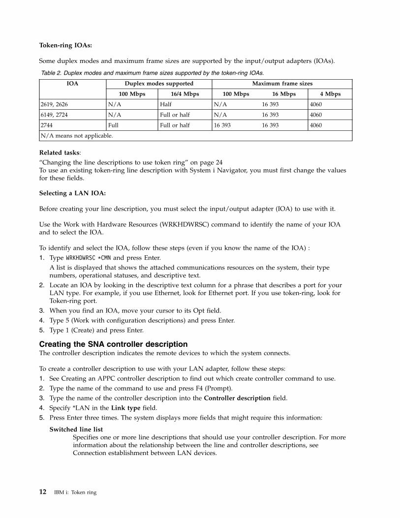
Token-ring IOAs:
Some duplex modes and maximum frame sizes are supported by the input/output adapters (IOAs).
Table 2. Duplex modes and maximum frame sizes supported by the token-ring IOAs.
IOA Duplex modes supported Maximum frame sizes
100 Mbps 16/4 Mbps 100 Mbps 16 Mbps 4 Mbps
2619, 2626 N/A Half N/A 16 393 4060
6149, 2724 N/A Full or half N/A 16 393 4060
2744 Full Full or half 16 393 16 393 4060
N/A means not applicable.
Related tasks:“Changing the line descriptions to use token ring” on page 24To use an existing token-ring line description with System i Navigator, you must first change the valuesfor these fields.
Selecting a LAN IOA:
Before creating your line description, you must select the input/output adapter (IOA) to use with it.
Use the Work with Hardware Resources (WRKHDWRSC) command to identify the name of your IOAand to select the IOA.
To identify and select the IOA, follow these steps (even if you know the name of the IOA) :1. Type WRKHDWRSC *CMN and press Enter.
A list is displayed that shows the attached communications resources on the system, their typenumbers, operational statuses, and descriptive text.
2. Locate an IOA by looking in the descriptive text column for a phrase that describes a port for yourLAN type. For example, if you use Ethernet, look for Ethernet port. If you use token-ring, look forToken-ring port.
3. When you find an IOA, move your cursor to its Opt field.4. Type 5 (Work with configuration descriptions) and press Enter.5. Type 1 (Create) and press Enter.
Creating the SNA controller descriptionThe controller description indicates the remote devices to which the system connects.
To create a controller description to use with your LAN adapter, follow these steps:1. See Creating an APPC controller description to find out which create controller command to use.2. Type the name of the command to use and press F4 (Prompt).3. Type the name of the controller description into the Controller description field.4. Specify *LAN in the Link type field.5. Press Enter three times. The system displays more fields that might require this information:
Switched line listSpecifies one or more line descriptions that should use your controller description. For moreinformation about the relationship between the line and controller descriptions, seeConnection establishment between LAN devices.
12 IBM i: Token ring
Remote control pointNames the local control point of the remote system. Use the Display Network Attributes(DSPNETA) command on the remote system to view its local control point name.
Exchange identifierContains the exchange identifier for your system. Advanced Program-to-ProgramCommunication (APPC) requires the ID. This ID has two parts. To determine the value for thefirst part, press F1 (Help) when your cursor is on this field. You can get the value for thesecond part from the line description on the remote system that is used to connect to yoursystem. To understand the purpose of exchange identifiers, see How LAN devices identifythemselves.
Local exchange identifierIdentifies your system to the host system. This field exists only in the host controllerdescription. Parallel connections between your system and a Systems Network Architecture(SNA) host require an exchange identifier.
Initial connectionDetermines whether the controller description initiates connection requests (*DIAL), or waitsfor incoming connection requests (*ANS).
If you specify *DIAL and want to adjust the polling duration or frequency, change the LANconnection retry (LANCNNRTY) or LAN connection timer (LANCNNTMR) field.
LAN remote adapter addressContains the address of the remote input/output adapter (IOA). To find this address, seeViewing the address of your LAN IOA. If you are using the preset address of the adapter, seeLAN IOA addresses to minimize your reconfiguration work.
LAN destination service access pointContains the source service access point (SSAP) value from the controller description that ison the remote device. For more information about service access points (SAPs), see SNAconnections to LAN protocols.
LAN source service access pointContains a value from the SSAP list of the line description that is associated with thiscontroller description.
6. Press Enter three times to create the description.Related concepts:“Connection establishment between LAN devices” on page 2If you use Systems Network Architecture (SNA) with a LAN protocol, follow these instructions toestablish a connection between the LAN devices.“SNA exchange identifiers” on page 3To establish a connection, your system and the remote device exchange information that includes theexchange identification (XID).“How LAN devices identify themselves” on page 3During the connection process, your system and the remote device exchange information with each otherto ensure connection to the correct system and device.“Which LAN device initiates the connection” on page 4In a Systems Network Architecture (SNA) environment, you can determine who initiates the connectionrequest and who waits for an incoming connection request.“Dial mode (SNA)” on page 4To send a connection request to a remote device, use the dial mode, which is used by Systems NetworkArchitecture (SNA) controller descriptions.“Answer mode (SNA)” on page 5If you specify the answer mode, the input/output adapter (IOA) cannot send connection requests, butcan respond to incoming connection requests.
Token ring 13
“The LANCNNTMR and LANCNNRTY parameters” on page 32Your Systems Network Architecture (SNA) controller description has two parameters: LAN connectiontimer (LANCNNTMR) and LAN connection retry (LANCNNRTY). They work together to define thefrequency and persistence of polling the remote station to establish a connection.“LAN IOA addresses” on page 8In a Systems Network Architecture (SNA) environment, you can determine the address for eachinput/output adapter (IOA).“SNA connections to LAN protocols” on page 5Systems Network Architecture (SNA) can be connected to a LAN protocol by using one or more serviceaccess points (SAPs).Related tasks:“Viewing the address of your LAN IOA” on page 28To configure a controller description, you must specify the address of the remote input/output adapter(IOA).Related information:Creating an APPC controller description
Creating the SNA device descriptionThe device description describes the communications device used by the remote device.
The device description contains no LAN-specific parameters.
To create the Systems Network Architecture (SNA) device description, follow these steps:1. Determine which create command to use in Creating device descriptions for APPC connections (this
information also has other commands for Advanced Peer-to-Peer Networking (APPN) devices, SingleNetwork Point (SNPT) devices, and so on).
2. Type the name of the command to use and press F4 (Prompt).3. Type the name of the device description into the Device description field.4. Complete these fields as described:
Remote locationThe name from the Local location field of the device description that is on the remote device.If the Local location field contains *NETATR, use the Display Network Attributes (DSPNETA)command at the remote device. Use this command to view the name that is specified by theDefault local location field.
Remote network identifierThe network identifier of the remote system. To find this value, use the Display NetworkAttributes (DSPNETA) command at the remote system to locate the Local network ID field.Advanced Program-Program Communication (APPC) device descriptions use the Remotenetwork identifier field.
5. Press Enter twice to create the description.Related concepts:“SNA connections to LAN protocols” on page 5Systems Network Architecture (SNA) can be connected to a LAN protocol by using one or more serviceaccess points (SAPs).“Dial mode (SNA)” on page 4To send a connection request to a remote device, use the dial mode, which is used by Systems NetworkArchitecture (SNA) controller descriptions.“Answer mode (SNA)” on page 5If you specify the answer mode, the input/output adapter (IOA) cannot send connection requests, butcan respond to incoming connection requests.Related information:
14 IBM i: Token ring
Creating device descriptions for APPC connections
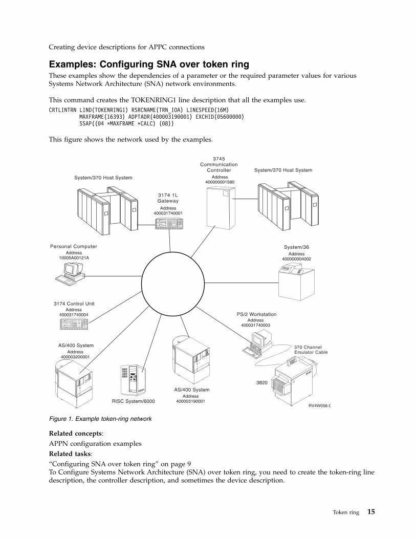
Examples: Configuring SNA over token ringThese examples show the dependencies of a parameter or the required parameter values for variousSystems Network Architecture (SNA) network environments.
This command creates the TOKENRING1 line description that all the examples use.CRTLINTRN LIND(TOKENRING1) RSRCNAME(TRN_IOA) LINESPEED(16M)
MAXFRAME(16393) ADPTADR(400003190001) EXCHID(05600000)SSAP((04 *MAXFRAME *CALC) (08))
This figure shows the network used by the examples.
Related concepts:APPN configuration examplesRelated tasks:“Configuring SNA over token ring” on page 9To Configure Systems Network Architecture (SNA) over token ring, you need to create the token-ring linedescription, the controller description, and sometimes the device description.
Figure 1. Example token-ring network
Token ring 15
Example: Connecting a system to another systemThis example shows how to create Advanced Program-to-Program Communication (APPC) over atoken-ring connection from your system to another system.
The name of the local system is LOCAL, and the name of the remote system is REMOTE.
Note: Because all the examples use the same token-ring line description, this example discusses only thecontroller and device descriptions.
Focus on these points in this example:v The service access points (SAPs) in the controller descriptions. For more information about SAPs, see
SNA connections to LAN protocols.v The adapter address used by a controller description must match the address that is used in the line
description on the remote device. This table shows the adapter addresses that are used by the line andcontroller descriptions on both systems.
Table 3. Local and remote adapter addresses
LOCAL REMOTE
Adapter address in the line description 400 003 190 001 400 003 200 001
Adapter address referred to by the controllerdescription
400 003 200 001 400 003 190 001
v The way a system identifies the other system to which it connects. Both sides must use the samemethod. These are the methods:– Only use the Remote exchange identifier parameter.– Use the Remote network identifier and the Remote control point name parameters.
In this example, each system uses the Remote network identifier and the Remote control point name(RMTCPNAME) parameters to indicate the system to which it connects.Note that within a system the remote network identifier must be the same in the controller and devicedescription. Because the example uses the default value of *NETATR for the Remote network identifierparameter, this parameter is not shown.Get the value for the Remote control point name parameter from the other system. To do this, use theDisplay Network Attributes (DSPNETA) command on the other system and locate the Local controlpoint name field.
TOKENRING2:
This example uses this line description on the remote system.CRTLINTRN LIND(TOKENRING2) RSRCNAME(TRN_IOA) LINESPEED(16M)
MAXFRAME(16393) ADPTADR(400003200001) EXCHID(05600000)SSAP((04 *MAXFRAME *CALC) (08 *MAXFRAME *CALC))TEXT(’Line description for 400003200001’)
Controller descriptions:
These examples show the controller descriptions that are used on the local and remote systems.CRTCTLAPPC CTLD(LOCAL_CD) LINKTYPE(*LAN) SWTLINLST(TOKENRING1)
RMTCPNAME(REMOTECP) ADPTADR(400003200001) DSAP(04)SSAP(08) TEXT(’Controller description on LOCAL’)
CRTCTLAPPC CTLD(REMOTE_CD) LINKTYPE(*LAN) SWTLINLST(TOKENRING2)RMTCPNAME(LOCALCP) ADPTADR(400003190001) DSAP(08)SSAP(04) TEXT(’Controller description on REMOTE’)
16 IBM i: Token ring
Device descriptions:
In the device descriptions, the Remote network identifier (RMTNETID) parameter needs to match thelocal network identifier of the remote system. You must use the Display Network Attributes (DSPNETA)command on the remote system to view the local network identifier.CRTDEVAPPC DEVD(LOCAL_DD) RMTLOCNAME(REMOTE) LCLLOCNAME(LOCAL)
CTL(LOCAL_CD) MODE(BLANK)TEXT(’APPC device description describing system REMOTE’)
CRTDEVAPPC DEVD(REMOTE_DD) RMTLOCNAME(LOCAL) LCLLOCNAME(REMOTE)CTL(REMOTE_CD) MODE(BLANK)TEXT(’APPC device description describing system LOCAL’)
Related concepts:“SNA connections to LAN protocols” on page 5Systems Network Architecture (SNA) can be connected to a LAN protocol by using one or more serviceaccess points (SAPs).
Example: Connecting the system to itselfThis example connects your system to itself. That is, the tokens travel around the local token-ringnetwork before returning to your system.
You can do the example to test an application within your system before testing it in the network.Because all the examples use the same token-ring line description, this example discusses only thecontroller and device descriptions.
Two sets of controller and device descriptions connect your system to itself. The first set dials (initiates) aconnection request, and the second set answers (accepts) the connection request.
In this example, focus on these points:v Use a different source service access point (SSAP) for each controller.v Use the same adapter address in both controller descriptions.v Use dial mode in one controller description and answer mode in the other.
Dial command set:CRTCTLAPPC CTLD(DIAL_CD) LINKTYPE(*LAN) APPN(*NO) INLCNN(*DIAL)
SWTLINLST(TOKENRING1) ADPTADR(400003190001)DSAP(08) SSAP(04)TEXT(’Link from SAP 04 to 08’)
CRTDEVAPPC DEVD(DIAL_DD) RMTLOCNAME(ANS) LCLLOCNAME(DIAL)CTL(DIAL_CD) MODE(BLANK) APPN(*NO)
Answer command set:CRTCTLAPPC CTLD(ANS_CD) LINKTYPE(*LAN) APPN(*NO) INLCNN(*ANS)
SWTLINLST(TOKENRING1) ADPTADR(400003190001)DSAP(04) SSAP(08)TEXT(’Link from SAP 08 to 04’)
CRTDEVAPPC DEVD(ANS_DD) RMTLOCNAME(DIAL) LCLLOCNAME(ANS)CTL(ANS_CD) MODE(BLANK) APPN(*NO)
Example: Connecting a system to a 3745 hostThis example shows how to connect your system to a 3745 host, and how you can configure the host.
Focus on these points for this example:v The controller description destination service access point (DSAP) must specify 04 to connect to the
host. The example does not show this parameter because 04 is the default.
Token ring 17
v The host can refer to only service access points (SAPs) 04 through 94; therefore, your service sourceaccess point (SSAP) must be within this range. The example does not show this parameter because ituses the default value of 04.
Controller description:CRTCTLHOST CTLD(TRLANHOST) LINKTYPE(*LAN) SWTLINLST(TOKENRING1)
RMTCPNAME(LANAPPN) LCLEXCHID(*LIND)ADPTADR(4000000001580) NODETYPE(*LENNODE)TEXT(’Controller description describing the 3745 host’)
Device descriptions:CRTDEVHOST DEVD(TRLANEML) LOCADR(01) RMTLOCNAME(HOST)
CTL(TRLANHOST) APPTYPE(*EML)TEXT(’3270 emulation over TOKENRING1’)
CRTDEVHOST DEVD(TRLANPRT) LOCADR(0C) RMTLOCNAME(HOST)CTL(TRLANHOST) APPTYPE(*EML) EMLDEV(3287)TEXT(’3270 printer emulation over TOKENRING1’)
CRTDEVDSP DEVD(TRLANDHCF) DEVCLS(*RMT) TYPE(3277) MODEL(*DHCF)LOCADR(02) CTL(TRLANHOST) TEXT(’DHCF over TOKENRING1’)
Host configuration:
On the host, you must generate a physical and a logical configuration before the system can connect to it.
Example: Creating a host physical configuration:
The network control program (NCP) generation produces the physical configuration that is necessary toconnect the 3745 Communication Controller to your system.
The system administrator creates the NCP generation for the GROUP and LINE macroinstructions.
You must ensure that the location address (LOCADD) parameter matches the Remote adapter address(ADPTADR) field of the controller description. This example shows the LOCADD parameter in bold:R1G006P GROUP ECLTYPE=PHYSICALR1080P LINE ADDRESS=(080,FULL),LOCADD=(400 000 001 580),PORTADD=01,
ISTATUS=INACTIVER1080PA PU ADDR=01,ISTATUS=INACTIVER1080PA1 LU LOCADDR=0,
LUDR=NOR1G006L GROUP ECLTYPE=LOGICAL,
PHYPORT=80R108000 LINER108000A PU MAXLU=32R108001 LINER108001A PU MAXLU=32R108002 LINER108002A PU MAXLU=32R108003 LINER108003A PU MAXLU=32R108004 LINER108004A PU MAXLU=32R108005 LINER108005A PU MAXLU=32R108006 LINER108006A PU MAXLU=32R108007 LINER108007A PU MAXLU=32
18 IBM i: Token ring
Note: This example is valid only on Network Control Program (NCP) Version 4.2 and VirtualTelecommunications Access Method (VTAM®) Version 3.1.1. Different NCP or VTAM levels might requiredifferent parameters.Related concepts:“Example: Creating a host logical configuration”The network control program generation (NCP) generation produces the logical configuration to connectthe 3745 Communication Controller to your system.
Example: Creating a host logical configuration:
The network control program generation (NCP) generation produces the logical configuration to connectthe 3745 Communication Controller to your system.
This example configuration is valid only on Network Control Program (NCP) Version 4.2 and VirtualTelecommunications Access Method (VTAM) Version 3.1.1. Different NCP or VTAM levels might requiredifferent parameters.
In this example, focus on these points:v Identifier block (IDBLK) and identifier number (IDNUM).v Dial number (DIALNO).
The concatenation of the IDBLK and IDNUM values must match the Local exchange identifier(LCLEXCHID) value of your controller description. In this example, because the controller descriptionspecifies *LIND in the LCLEXCHID field, the value comes from the Exchange identifier (EXCHID) fieldof the line description.
The DIALNO parameter specifies the source service access point (SSAP) and the adapter address of yoursystem. This is the format of DIALNO:aabb4000cccccccc
This is the explanation of the format:v aa is the value of the PORTADD parameter that is specified in the physical configuration.v bb is the SSAP value from your controller description.v 4000cccccccc is the address of your adapter that is specified in the line description. In this example, the
address is 400 003 190 001 (see the ADPTADR parameter of line description TOKENRING1).
This logical configuration example shows the IDBLK, IDNUM, and DIALNO parameters in bold:SW3270C VBUILD TYPE=SWNET, REQUIRED PARAMETER X
MAXNO=8, *MAXGRP=5
S3270C PU ADDR=C1, 8 BIT STATION UNIQUE ADDRESS XDISCNT=NO, ACCEPT DISCONTACT FROM PU (DEFAULT) XIDBLK=056, 12 BIT BLOCK NUMBER FOR STATION XIDNUM=00000, 20 BIT ID NUMBER FOR SYSTEM XMAXDATA=1994,MAXPATH=8, MAXIMUM OF 8 STATIONS MAY BE CALLED XNETID=AS400, LOCAL NETWORK ID ON System i XMAXOUT=7, 7 PIUS TO STATION BEFORE RESPONSE XPACING=7, NCP SENDS 7 TO LU AND MARKS FIRST XPASSLIM=7, MAXIMUM OF 7 CONTIGUOUS PIUS XPUTYPE=2, TYPE OF STATION CALLING IN XISTATUS=ACTIVE, ACTIVATE WITH MAJOR NODE XMODETAB=LOGMOD38, I/S DEFINED TABLE *SSCPFM=USSSCS, VTAM TO STRIP/ADD MEDIA CONTROL CHAR *VPACING=7 VTAM SENDS 7 TO NCP AND MARKS FIRST
S348L80 PATH GRPNM=R1G006L,DIALNO=0104400003190001,PID=1 319-R1080SW327C01 LU LOCADDR=1, System i LOCADDR VALUE X’01’ X
Token ring 19
ISTATUS=ACTIVE ACTIVATE WITH MAJOR NODESW327C02 LU LOCADDR=2, System i LOCADDR VALUE X’02’ X
ISTATUS=ACTIVE ACTIVATE WITH MAJOR NODESW327C12 LU LOCADDR=12, System i LOCADDR VALUE X’0C’ X
ISTATUS=ACTIVE ACTIVATE WITH MAJOR NODE
Related concepts:“Example: Creating a host physical configuration” on page 18The network control program (NCP) generation produces the physical configuration that is necessary toconnect the 3745 Communication Controller to your system.
Example: Connecting a system to a 3174 Model 1L gatewayIn this example, a 3174 Control Unit functions as a gateway to connect two systems that support differentnetwork architectures. You can also find an example to connect the gateway to your system at the end ofthis example.
Because all the examples use the same token-ring line description, this example discusses only thecontroller and device descriptions. This example does not show the source service access point (SSAP)and destination service access point (DSAP) parameters because they use the default values.
Controller description:CRTCTLHOST CTLD(TRLANHOST2) LINKTYPE(*LAN) SWTLINLST(TOKENRING1)
RMTCPNAME(*ANY) ADPTADR(400031740001)TEXT(’Controller description describing the 3174 Gateway’)
Device description:
Although this device description example is not specific to token-ring networks, you can use it toconfigure an emulation display:CRTDEVHOST DEVD(TRLANEML2) LOCADR(01) RMTLOCNAME(HOST2)
CTL(TRLANHOST2) APPTYPE(*EML)TEXT(’3270 emulation for Host2’)
Related concepts:“SNA connections to LAN protocols” on page 5Systems Network Architecture (SNA) can be connected to a LAN protocol by using one or more serviceaccess points (SAPs).
Example: Creating the NCP generation for a 3174 gateway:
The system administrator creates the network control program (NCP) generation to connect your systemto the 3174.
You must ensure that the address specified by the control-unit address (CUADDR) parameter is correct.The last two characters of this parameter must match the Control Unit Address value. This value isspecified in the Ring Address Assignment display and the Ring Transmission Definition display of the3174.
Note: This example is valid on Network Control Program (NCP) Version 4.2 and VirtualTelecommunications Access Method (VTAM) Version 3.1.1. Different NCP or VTAM levels might requiredifferent parameters.
This is the NCP GEN (the CUADDR parameter is in bold):R13B1 VBUILD TYPE=LOCALR13B0A PU CUADDR=3B1,
XDISCNT=(NO,F), XISTATUS=ACTIVE, XPUTYPE=2, X
20 IBM i: Token ring
SPAN=(SYSPGMR), XSSCPFM=USSSCS, XVPACING=7
R13B102 LU DLOGMOD=P6ES2, XENCR=NONE, XISTATUS=ACTIVE, XLOCADDR=2, XLOGAPPL=SAMON, XMODETAB=LOGMOD38, XSPAN=(SYSPGMR), XSSCPFM=USSSCS, XVPACING=7
Example: Connecting a system to a 3174 subsystem control unit:
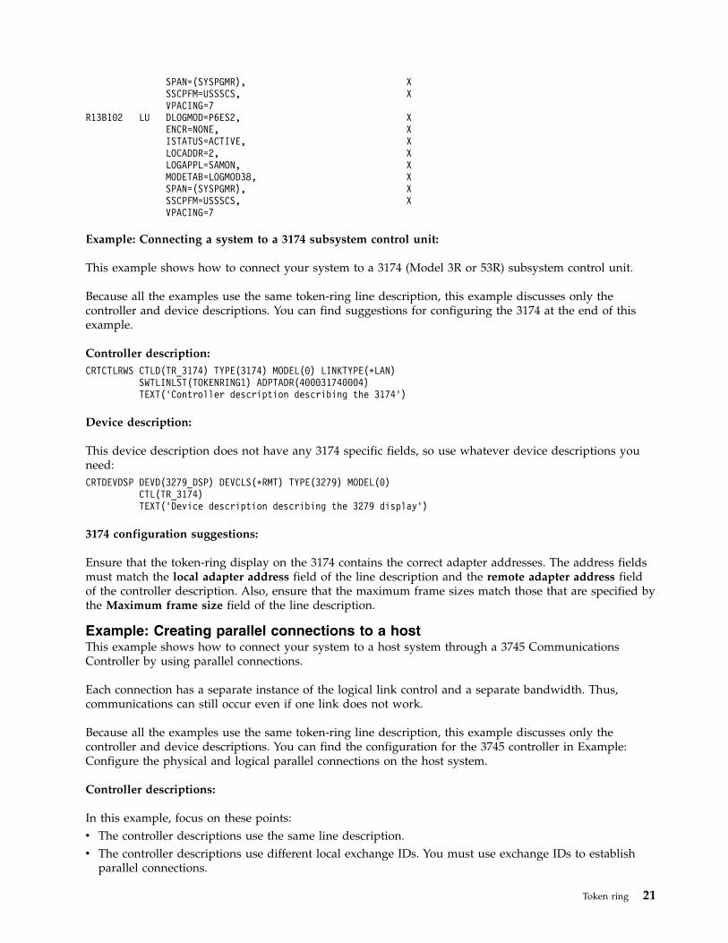
This example shows how to connect your system to a 3174 (Model 3R or 53R) subsystem control unit.
Because all the examples use the same token-ring line description, this example discusses only thecontroller and device descriptions. You can find suggestions for configuring the 3174 at the end of thisexample.
Controller description:CRTCTLRWS CTLD(TR_3174) TYPE(3174) MODEL(0) LINKTYPE(*LAN)
SWTLINLST(TOKENRING1) ADPTADR(400031740004)TEXT(’Controller description describing the 3174’)
Device description:
This device description does not have any 3174 specific fields, so use whatever device descriptions youneed:CRTDEVDSP DEVD(3279_DSP) DEVCLS(*RMT) TYPE(3279) MODEL(0)
CTL(TR_3174)TEXT(’Device description describing the 3279 display’)
3174 configuration suggestions:
Ensure that the token-ring display on the 3174 contains the correct adapter addresses. The address fieldsmust match the local adapter address field of the line description and the remote adapter address fieldof the controller description. Also, ensure that the maximum frame sizes match those that are specified bythe Maximum frame size field of the line description.
Example: Creating parallel connections to a hostThis example shows how to connect your system to a host system through a 3745 CommunicationsController by using parallel connections.
Each connection has a separate instance of the logical link control and a separate bandwidth. Thus,communications can still occur even if one link does not work.
Because all the examples use the same token-ring line description, this example discusses only thecontroller and device descriptions. You can find the configuration for the 3745 controller in Example:Configure the physical and logical parallel connections on the host system.
Controller descriptions:
In this example, focus on these points:v The controller descriptions use the same line description.v The controller descriptions use different local exchange IDs. You must use exchange IDs to establish
parallel connections.
Token ring 21
v The controller descriptions use different source service access points (SSAPs).v The 3745 Communications Controller requires that you specify 04 for the destination service access
point (DSAP).
Note: By using the code examples, you agree to the terms of the “Code license and disclaimerinformation” on page 40.CRTCTLHOST CTLD(CTL_1A) LINKTYPE(*LAN) APPN(*NO)
SWTLINLST(TOKENRING1) LCLEXCHID(056A001A)ADPTADR(400000001592) DSAP(04) SSAP(04)TEXT(’Controller for the first link’)
CRTCTLHOST CTLD(CTL_2A) LINKTYPE(*LAN) APPN(*NO)SWTLINLST(TOKENRING1) LCLEXCHID(056A002A)ADPTADR(400000001592) DSAP(04) SSAP(08)TEXT(’Controller for second link’)
Device descriptions for CTL_1A:
These commands create the device descriptions that are used with the CTL_1A controller description:CRTDEVDSP DEVD(DSPA001A02) DEVCLS(*RMT) TYPE(3279) MODEL(0)
LOCADR(02) CTL(CTL_1A) APPTYPE(*NRF)TEXT(’NRF device, LOCADDR 02’)
CRTDEVDSP DEVD(DSPA001A03) DEVCLS(*RMT) TYPE(3279) MODEL(0)LOCADR(03) CTL(CTL_1A) APPTYPE(*NRF)TEXT(’NRF device, LOCADDR 03’)
CRTDEVHOST DEVD(EMLA001A04) LOCADR(04) RMTLOCNAME(SWXIDA04)CTL(CTL_1A) APPTYPE(*EML)TEXT(’Emulation display, LOCADDR 04’)
CRTDEVPRT DEVD(PRTA001A05) DEVCLS(*RMT) TYPE(3287) MODEL(0)LOCADR(05) CTL(SWTRNCTL1A) APPTYPE(*NRF)LOGON(’LOGON APPLID(NRF2A07) LOGMODE(SCSTRYR)’)TEXT(’NRF printer, LOCADDR 05’)
Device descriptions for CTL_2A:
These commands create the device descriptions that are used with the CTL_2A controller description:CRTDEVDSP DEVD(DSPA002A02) DEVCLS(*RMT) TYPE(3279) MODEL(0)
LOCADR(02) CTL(CTL_2A) APPTYPE(*NRF)TEXT(’NRF device, LOCADDR 02’)
CRTDEVHOST DEVD(EMLA002A04) LOCADR(04) RMTLOCNAME(SWXIDB04)CTL(CTL_2A) APPTYPE(*EML)TEXT(’Emulation display, LOCADDR 04’)
CRTDEVPRT DEVD(PRTA002A05) DEVCLS(*RMT) TYPE(3287) MODEL(0)LOCADR(05) CTL(CTL_2A) APPTYPE(*NRF)LOGON(’LOGON APPLID(NRF2A07) LOGMODE(SCSTRYR)’)TEXT(’NRF printer, LOCADDR 05’)
Related concepts:“SNA connections to LAN protocols” on page 5Systems Network Architecture (SNA) can be connected to a LAN protocol by using one or more serviceaccess points (SAPs).
Example: Configuring the physical and logical parallel connections on the host system:
This example shows a network control program (NCP) generation created by a system administrator toconnect the 3745 Communication Controller to the system.
22 IBM i: Token ring
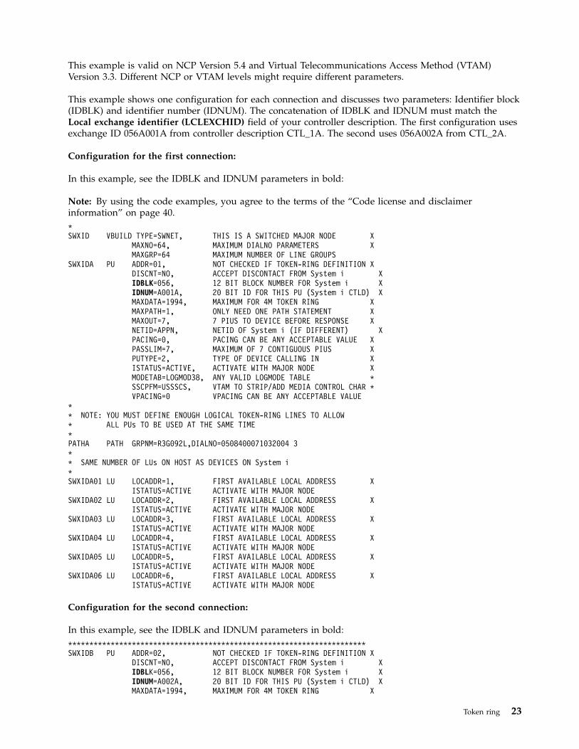
This example is valid on NCP Version 5.4 and Virtual Telecommunications Access Method (VTAM)Version 3.3. Different NCP or VTAM levels might require different parameters.
This example shows one configuration for each connection and discusses two parameters: Identifier block(IDBLK) and identifier number (IDNUM). The concatenation of IDBLK and IDNUM must match theLocal exchange identifier (LCLEXCHID) field of your controller description. The first configuration usesexchange ID 056A001A from controller description CTL_1A. The second uses 056A002A from CTL_2A.
Configuration for the first connection:
In this example, see the IDBLK and IDNUM parameters in bold:
Note: By using the code examples, you agree to the terms of the “Code license and disclaimerinformation” on page 40.*SWXID VBUILD TYPE=SWNET, THIS IS A SWITCHED MAJOR NODE X
MAXNO=64, MAXIMUM DIALNO PARAMETERS XMAXGRP=64 MAXIMUM NUMBER OF LINE GROUPS
SWXIDA PU ADDR=01, NOT CHECKED IF TOKEN-RING DEFINITION XDISCNT=NO, ACCEPT DISCONTACT FROM System i XIDBLK=056, 12 BIT BLOCK NUMBER FOR System i XIDNUM=A001A, 20 BIT ID FOR THIS PU (System i CTLD) XMAXDATA=1994, MAXIMUM FOR 4M TOKEN RING XMAXPATH=1, ONLY NEED ONE PATH STATEMENT XMAXOUT=7, 7 PIUS TO DEVICE BEFORE RESPONSE XNETID=APPN, NETID OF System i (IF DIFFERENT) XPACING=0, PACING CAN BE ANY ACCEPTABLE VALUE XPASSLIM=7, MAXIMUM OF 7 CONTIGUOUS PIUS XPUTYPE=2, TYPE OF DEVICE CALLING IN XISTATUS=ACTIVE, ACTIVATE WITH MAJOR NODE XMODETAB=LOGMOD38, ANY VALID LOGMODE TABLE *SSCPFM=USSSCS, VTAM TO STRIP/ADD MEDIA CONTROL CHAR *VPACING=0 VPACING CAN BE ANY ACCEPTABLE VALUE
** NOTE: YOU MUST DEFINE ENOUGH LOGICAL TOKEN-RING LINES TO ALLOW* ALL PUs TO BE USED AT THE SAME TIME*PATHA PATH GRPNM=R3G092L,DIALNO=0508400071032004 3** SAME NUMBER OF LUs ON HOST AS DEVICES ON System i*SWXIDA01 LU LOCADDR=1, FIRST AVAILABLE LOCAL ADDRESS X
ISTATUS=ACTIVE ACTIVATE WITH MAJOR NODESWXIDA02 LU LOCADDR=2, FIRST AVAILABLE LOCAL ADDRESS X
ISTATUS=ACTIVE ACTIVATE WITH MAJOR NODESWXIDA03 LU LOCADDR=3, FIRST AVAILABLE LOCAL ADDRESS X
ISTATUS=ACTIVE ACTIVATE WITH MAJOR NODESWXIDA04 LU LOCADDR=4, FIRST AVAILABLE LOCAL ADDRESS X
ISTATUS=ACTIVE ACTIVATE WITH MAJOR NODESWXIDA05 LU LOCADDR=5, FIRST AVAILABLE LOCAL ADDRESS X
ISTATUS=ACTIVE ACTIVATE WITH MAJOR NODESWXIDA06 LU LOCADDR=6, FIRST AVAILABLE LOCAL ADDRESS X
ISTATUS=ACTIVE ACTIVATE WITH MAJOR NODE
Configuration for the second connection:
In this example, see the IDBLK and IDNUM parameters in bold:**********************************************************************SWXIDB PU ADDR=02, NOT CHECKED IF TOKEN-RING DEFINITION X
DISCNT=NO, ACCEPT DISCONTACT FROM System i XIDBLK=056, 12 BIT BLOCK NUMBER FOR System i XIDNUM=A002A, 20 BIT ID FOR THIS PU (System i CTLD) XMAXDATA=1994, MAXIMUM FOR 4M TOKEN RING X
Token ring 23
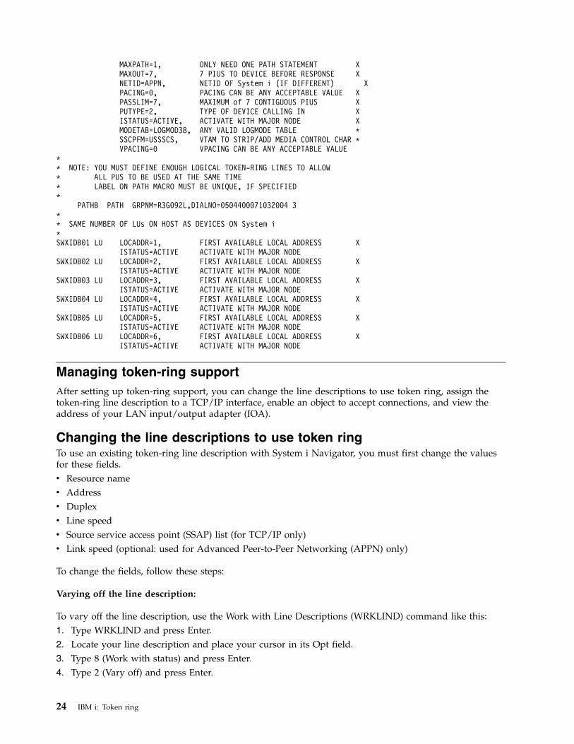
MAXPATH=1, ONLY NEED ONE PATH STATEMENT XMAXOUT=7, 7 PIUS TO DEVICE BEFORE RESPONSE XNETID=APPN, NETID OF System i (IF DIFFERENT) XPACING=0, PACING CAN BE ANY ACCEPTABLE VALUE XPASSLIM=7, MAXIMUM of 7 CONTIGUOUS PIUS XPUTYPE=2, TYPE OF DEVICE CALLING IN XISTATUS=ACTIVE, ACTIVATE WITH MAJOR NODE XMODETAB=LOGMOD38, ANY VALID LOGMODE TABLE *SSCPFM=USSSCS, VTAM TO STRIP/ADD MEDIA CONTROL CHAR *VPACING=0 VPACING CAN BE ANY ACCEPTABLE VALUE
** NOTE: YOU MUST DEFINE ENOUGH LOGICAL TOKEN-RING LINES TO ALLOW* ALL PUS TO BE USED AT THE SAME TIME* LABEL ON PATH MACRO MUST BE UNIQUE, IF SPECIFIED*
PATHB PATH GRPNM=R3G092L,DIALNO=0504400071032004 3** SAME NUMBER OF LUs ON HOST AS DEVICES ON System i*SWXIDB01 LU LOCADDR=1, FIRST AVAILABLE LOCAL ADDRESS X
ISTATUS=ACTIVE ACTIVATE WITH MAJOR NODESWXIDB02 LU LOCADDR=2, FIRST AVAILABLE LOCAL ADDRESS X
ISTATUS=ACTIVE ACTIVATE WITH MAJOR NODESWXIDB03 LU LOCADDR=3, FIRST AVAILABLE LOCAL ADDRESS X
ISTATUS=ACTIVE ACTIVATE WITH MAJOR NODESWXIDB04 LU LOCADDR=4, FIRST AVAILABLE LOCAL ADDRESS X
ISTATUS=ACTIVE ACTIVATE WITH MAJOR NODESWXIDB05 LU LOCADDR=5, FIRST AVAILABLE LOCAL ADDRESS X
ISTATUS=ACTIVE ACTIVATE WITH MAJOR NODESWXIDB06 LU LOCADDR=6, FIRST AVAILABLE LOCAL ADDRESS X
ISTATUS=ACTIVE ACTIVATE WITH MAJOR NODE
Managing token-ring supportAfter setting up token-ring support, you can change the line descriptions to use token ring, assign thetoken-ring line description to a TCP/IP interface, enable an object to accept connections, and view theaddress of your LAN input/output adapter (IOA).
Changing the line descriptions to use token ringTo use an existing token-ring line description with System i Navigator, you must first change the valuesfor these fields.v Resource namev Addressv Duplexv Line speedv Source service access point (SSAP) list (for TCP/IP only)v Link speed (optional: used for Advanced Peer-to-Peer Networking (APPN) only)
To change the fields, follow these steps:
Varying off the line description:
To vary off the line description, use the Work with Line Descriptions (WRKLIND) command like this:1. Type WRKLIND and press Enter.2. Locate your line description and place your cursor in its Opt field.3. Type 8 (Work with status) and press Enter.4. Type 2 (Vary off) and press Enter.
24 IBM i: Token ring
5. If your line description does not vary off, place your cursor on the error message and press F1 (Help)to view more information about the error.
6. If no error occurs, press F3 (Exit) to exit the command, and continue with the next step to change thefield values.
Changing the field values:
Now you must change the values in the fields by using the Change Line Description (Token Ring)(CRTLINTRN) command.
To do this, follow these steps:1. Record the name of the token-ring card by doing these steps:
a. Type WRKHDWRSC *CMN and press Enter.b. Search the Type column to locate the correct token-ring card.c. Record the name of the card that is found under the Resource column.d. Press F3 (Exit).
2. Type WRKLIND and press Enter.3. Locate the line description to change.4. Type 2 (Change) and press Enter.5. Type the name of the selected token–ring card into the Resource name field.6. In the Line speed field, indicate the speed of the input/output adapter (IOA).
Note: You can enable automatic ring-speed sensing when specifying *AUTO or 100M. Automaticsense starts initially at 100 Mbps. To use automatic sense successfully, you must ensure that yoursystem or the switch that the system connects to is enabled for ring-speed sensing. That is, youshould enable ring-speed sensing only on one device; otherwise, an incorrect speed might beselected.
7. Select the duplex mode to use with your IOA.
Note: Duplex mode negotiation occurs when you specify *AUTO or *FULL. The negotiation startsinitially at full-duplex mode. The switch must support this type of negotiation before you cansuccessfully use this function. If you are not familiar with the capabilities of the IOA, see Token-ringIOAs.
8. If you are using this line description with TCP/IP, ensure that source service access point (SSAP)X'AA' and its associated information are in the SSAP list field.
9. If needed, specify a maximum frame size.10. Press Enter to save your changes, and then press F3 (Exit).11. Continue with the next task. If you are using this line description with Systems Network
Architecture (SNA), enable the description to accept connections. If you are using this linedescription with TCP/IP, assign it to an interface.
Related concepts:“Token ring” on page 1This topic collection can help you plan, configure, manage, tune, and troubleshoot token-ring support forTCP/IP and Systems Network Architecture (SNA).“Supported token-ring functions” on page 2A range of token-ring technologies that support speeds of 4 Mbps, 16 Mbps, and 100 Mbps are supportedon the system. “Token-ring IOAs” on page 12Some duplex modes and maximum frame sizes are supported by the input/output adapters (IOAs).“SNA connections to LAN protocols” on page 5Systems Network Architecture (SNA) can be connected to a LAN protocol by using one or more service
Token ring 25
access points (SAPs).“Maximum frame size of token ring” on page 7The use of larger frame sizes can improve the performance of your system, because large frames requireless processing overhead than the same data that is divided up among many smaller frames.Related tasks:“Configuring TCP/IP over token ring” on page 9You can use System i Navigator to configure token-ring support for TCP/IP.“Enabling objects to accept connections” on page 27After configuring LAN support, you are ready to enable your configuration objects to accept connections.
“Assigning the token-ring line description to a TCP/IP interface”You can assign the token-ring line description to a new or an existing TCP/IP interface through System iNavigator.Related information:Troubleshooting
Assigning the token-ring line description to a TCP/IP interfaceYou can assign the token-ring line description to a new or an existing TCP/IP interface through System iNavigator.
After you change the existing line description that is used with the 100 Mbps adapter, you can assign thetoken-ring line description to a new or an existing TCP/IP interface through System i Navigator. You donot need to do this if you are using the line description with Systems Network Architecture (SNA).
Assigning the line description to a TCP/IP interface:
To assign the line description to a new interface, you must follow the procedure in Configuring TCP/IPover token ring to create the interface. During this creation process, you must choose your descriptionfrom a list of line descriptions.
Note: If other entities know the burned-in address of your old adapter, you must replace that addresswith the address of the 100 Mbps adapter. This is required if you want them to communicate with theadapter. You can use a locally administered address to avoid these kinds of changes in the future.
To associate your line description with an existing interface, do these steps:1. Install System i Navigator if you have not done so already.2. If this is the first time you are using System i Navigator to access your system, use the wizard to
configure TCP/IP on the system.3. In the navigation tree, expand the system that contains the changed line description.4. Select Network > Protocol.5. Right-click TCP/IP and select Interface.6. Double-click the interface to which you want to assign the line description.7. Click the Resource tab and select your line description from the Line name option.8. Click OK, and then click OK again.Related concepts:“Token ring” on page 1This topic collection can help you plan, configure, manage, tune, and troubleshoot token-ring support forTCP/IP and Systems Network Architecture (SNA).“LAN IOA addresses” on page 8In a Systems Network Architecture (SNA) environment, you can determine the address for eachinput/output adapter (IOA).
26 IBM i: Token ring
Related tasks:“Changing the line descriptions to use token ring” on page 24To use an existing token-ring line description with System i Navigator, you must first change the valuesfor these fields.“Configuring TCP/IP over token ring” on page 9You can use System i Navigator to configure token-ring support for TCP/IP.Related information:Customizing TCP/IP with iSeries Navigator
Enabling objects to accept connectionsAfter configuring LAN support, you are ready to enable your configuration objects to accept connections.
For Systems Network Architecture (SNA), you enable or vary on the line and controller descriptions. ForTCP/IP, you can enable or start the interface.
Varying on configuration objects:
To accept connections, you must vary on the configuration objects by using the Work with ConfigurationStatus (WRKCFGSTS) command as follows:1. Type WRKCFGSTS *LIN and press Enter.2. Locate your line description.3. Move your cursor to the Opt field of the line description, type 1 (Vary on), and press Enter.4. If the line description does not vary on successfully, press F3 (Exit). To view the error messages and to
find possible solutions, see Display message queues to solve communication problems.5. Press F3 (Exit).
If the line description varied on successfully, you need to do the same for the controller description if youcreated one. Vary on the controller description by using the same instructions for varying on the linedescription. Instead of specifying *LIN for the WRKCFGSTS command, you must specify *CTL.
Starting the TCP/IP interface:
To enable the interface, use System i Navigator to do these steps:1. From System i Navigator, expand the system that contains the TCP/IP interface to start.2. Select Network > Protocol.3. Right-click TCP/IP and select Interface.4. You can start the interface now, or every time TCP/IP starts.
a. To start the interface now:1) Select an inactive interface.2) Click Start.3) Click OK to close the dialog box.
b. To start the interface every time TCP/IP starts:
1) Double-click the interface.2) Select Start interface when TCP/IP is started.3) Click OK.
Related tasks:“Configuring TCP/IP over token ring” on page 9You can use System i Navigator to configure token-ring support for TCP/IP.
Token ring 27
“Configuring SNA over token ring” on page 9To Configure Systems Network Architecture (SNA) over token ring, you need to create the token-ring linedescription, the controller description, and sometimes the device description.“Changing the line descriptions to use token ring” on page 24To use an existing token-ring line description with System i Navigator, you must first change the valuesfor these fields.Related information:Displaying message queues to solve communication problemsTroubleshooting
Viewing the address of your LAN IOATo configure a controller description, you must specify the address of the remote input/output adapter(IOA).
On the remote system, use these procedures to view the locally administered address or the presetaddress:
Viewing the locally administered address:
To view the locally administered address, do these steps:1. Type DSPLIND description_name (where description_name is the name of the description to be
displayed) and press Enter.2. Locate the Local adapter address field to view the address of the adapter.3. Press F3 (Exit).
Viewing the preset address:
To view the preset address of the remote IOA, do these steps:1. Locate a line description that uses the IOA. This description must specify *ADPT in the Adapter
address field. If you cannot find such a line description, create it.2. Use the Work with Configuration Status (WRKCFGSTS) command to vary on the line description:
a. Type WRKCFGSTS *LIN and press Enter.b. Locate your line description and look for a status of varied on or active.c. If it is varied on or active, press F3 (Exit) and skip to step 3.d. Place your cursor on the Opt field of the line description, type 1 (Vary on), and press Enter.e. If your line description does not vary on, place your cursor on the error message and press F1
(Help) to view more information about the error.f. Press F3 (Exit).
3. Type DSPLIND description_name (where description_name is the name of your line description), andpress Enter.
4. Locate the Local adapter address field to view the preset address of the adapter.5. Press F3 (Exit).Related tasks:“Creating the SNA controller description” on page 12The controller description indicates the remote devices to which the system connects.
Configuration object commandsYou can view and use other commands that affect your line, controller, or device descriptions by usingthe GO command.
28 IBM i: Token ring
To view configuration objects, use these commands:v To view line description commands, type GO CMDLIND and press Enter.v To view controller description commands, type GO CMDCTLD and press Enter.v To view device description commands, type GO CMDDEVD and press Enter.
The following list shows other related commands that you can use with your descriptions. To use one ofthese commands, type the name of the command (that is shown in parentheses) and press F4 (Prompt):v Retrieve Configuration Status (RTVCFGSTS).v Vary Configuration (VRYCFG).v Save Configuration (SAVCFG).v Restore Configuration (RSTCFG).v Work with Configuration Status (WRKCFGSTS).
Tuning token-ring performanceTo improve the performance of your connections, you can adjust related token-ring parameters.v Adjust token-ring frame size.v Adjust token-ring timing.v Adjust token release timing. For 16 Mbps token-rings that use half duplex, you can increase
performance by changing the token-release value in the token-ring line description.
Other performance tips:
See this information for other tips that might improve the performance of the connection:
v You can find other tips about communication performance in Performance Management for IBM i .The Web site has PDF files that contain the Performance Capabilities Reference.
v See other tips for using Systems Network Architecture (SNA) over your LAN protocol in Improvinglocal area network performance.
Related concepts:“Supported token-ring functions” on page 2A range of token-ring technologies that support speeds of 4 Mbps, 16 Mbps, and 100 Mbps are supportedon the system. Related information:Improving local area network performance
Adjusting your LAN-frame sizeIf the remote bridge drops your frames, you might need to adjust your LAN-frame size.
When the remote bridge drops your frames, change your frame size:1. Determine the new frame size. The network administrator should know what your frame size should
be. You might also find that the frame size is contained within the QSYSOPR message queue inmessage CPF 5908.
2. Determine which configuration object and MAXFRAME parameter to change. To determine this, seeBridges dropping frames.
3. To change the parameter, see this information to determine which command to use:v Change line description commands:
– Use the CHGLINTRN command for token-ring line descriptions.v Change controller description commands:
– On an empty command line, type GO CMDCTL and press Enter.
Token ring 29
– Enter the appropriate command into the command line, and press Enter.– Type the name of your controller, and press Enter.
See Token-ring line description commands for instructions on how to use the change line descriptioncommands.
4. Press F9 to show all parameters.5. Locate the MAXFRAME parameter that you chose in step 2 on page 29.6. Specify the value that you found in step 1 on page 29.7. Press Enter to save your changes and exit the command.
Viewing the QSYSOPR message queue or other message queuesThe QSYSOPR message queue and other message queues contain messages that describe the error andmight contain possible solutions for the error. These messages are typically good places to begin yourtroubleshooting.
To view these messages, follow these steps:1. Type DSPMSG MSGQ (message_queue) on the command line and press Enter, where message queue is
QSYSOPR or the configured message queue.2. Locate the error messages created around the time the error occurred.3. Move your cursor to the error message of interest and press F1. The system displays more
information about the error.4. Note the cause code, the error description, and possible solutions. Also, record any message IDs, error
codes, reference codes, or reason codes.
Bridges dropping framesA remote bridge discards your frame if it does not support your frame size. Also, the network candiscard your frame if it does not support your frame size.
In a token-ring environment, the bridge informs the system that originated the connection of thesupported frame sizes. The system then automatically tries to reconnect with that frame size.
If you cannot configure the bridge to support your frame size or a larger frame size, adjust theMAXFRAME parameter to a value that is acceptable to the bridge. The system has these MAXFRAMEparameters that are shown in order of precedence:1. The source service access point (SSAP) MAXFRAME parameter in the line description.2. The MAXFRAME parameter in the line description (except Ethernet line descriptions).3. The MAXFRAME parameter in the controller description.
The SSAP MAXFRAME parameter affects only one device. That is, only that device uses a frame size ofSSAP MAXFRAME.
The MAXFRAME parameter that is in the line description affects all devices that use that description.
The MAXFRAME parameter that is in the controller description affects all lines and devices that use thatdescription.
You set the precedence when specifying a MAXFRAME value. If you define a value for the firstparameter (SSAP MAXFRAME) and then the second parameter, your system uses the value of the firstparameter. To use the value of the second parameter, you should not specify a value for the firstparameter.
Token-ring line description commandsThese procedures show how to create, change, delete, and display your token-ring line description.v To create your line description, see Creating the token-ring line description.
30 IBM i: Token ring
v To change or view your line description:1. Type CHGLINTRN on the command line, and press Enter.2. Type in the name of your description, and press Enter.3. Make your changes.4. Press Enter to save your changes, and exit the command.
v To delete your description use the Delete Line Description (DLTLIND) command. Type the statementbelow on the command line, and press Enter:DLTLIND (description)
Where description is the name of your description.v To display your line description, type the statement below on the command line, and press Enter:
DSPLIND LIND(description)
Where description is the name of your description.Related tasks:“Creating the token-ring line description” on page 10You can use the Create Line Description (CRTLINTRN) command to create a token-ring line description.
TimingTiming parameters are related to LAN performance. You can perform timing adjustments to improveLAN performance.
Timing parametersYou can make timing adjustments through the parameters of the Systems Network Architecture (SNA)controller description.
SNA controller descriptions (advanced program-to-program communication (APPC), SNA host, remoteworkstation, finance, and retail) have parameters that describe the behavior of the station. The parameterscan be used with all LAN protocols. The names of these parameters begin with the letters LAN.
The following table shows the LAN parameters and their default values (see the *CALC column). Youcan view all parameter values with the Display Controller Description (DSPCTLD) command when thecontroller is varied on.
Note: Reducing a parameter's value gives you quicker error detection, but it also reduces the time forerror recovery.
To change these parameters, see Changing timing parameters.
Parameter Description *CALC value
LANCNNTMR (LAN connection timer) The time to wait between requests toconnect.
seven seconds
LANCNNRTY (LAN connection retry) The number of times to poll forrequest to connect.
10
LANRSPTMR (LAN response timer) The time to wait before retransmittinga frame.
one second
LANFRMRTY (LAN frame retry) The number of times to retransmit aframe.
10
LANACKTMR (LAN acknowledge timer) The time to wait before sending anacknowledgment.
0.1 seconds
LANACKFRQ (LAN acknowledgment frequency) The number of frames toreceive before sending an acknowledgment.
one
Token ring 31
Parameter Description *CALC value
LANINACTMR (LAN inactivity timer) The time to wait before requesting aresponse from the remote station.
10 seconds
LANMAXOUT (LAN maximum outstanding) The number of outstandingframes allowed before requesting an acknowledgment fromthe remote station.
two
LANWDWSTP (LAN window step) An alternative to LANMAXOUT. UseLANWDWSTP to help alleviate network congestion.
*NONE
LANACCPTY (LAN access priority) The priority of the station. Stationswith higher priority have greater access to the token. (Usedfor token-ring only.)
zero
Related tasks:“Changing timing parameters” on page 36Changing timing parameters can help improve LAN performance.
The LANCNNTMR and LANCNNRTY parameters:
Your Systems Network Architecture (SNA) controller description has two parameters: LAN connectiontimer (LANCNNTMR) and LAN connection retry (LANCNNRTY). They work together to define thefrequency and persistence of polling the remote station to establish a connection.
LANCNNTMR specifies how long to wait before polling again. LANCNNRTY specifies how many timesto poll. If the system receives no response from the remote station after polling the number of timesspecified in the LANCNNRTY parameter, the following occurs:v The user is notified that contact with the station was unsuccessful.v The system places the controller description in answer mode.v If the remote station signals your system to try your connection inquiry again, your system attempts to
establish connection again.
Performance problems:
The default values of the parameters are designed for a single LAN and might cause a connection failurewhen you access a remote station through a remote bridge. The bridge might slow data traffic enoughthat the connection timer expires before the remote station's response reaches you. If this is the case, youshould increase the values of LANCNNTMR and LANCNNRTY.Related concepts:“Dial mode (SNA)” on page 4To send a connection request to a remote device, use the dial mode, which is used by Systems NetworkArchitecture (SNA) controller descriptions.Related tasks:“Creating the SNA controller description” on page 12The controller description indicates the remote devices to which the system connects.“Changing timing parameters” on page 36Changing timing parameters can help improve LAN performance.
The LANRSPTMR and LANFRMRTY parameters:
In your Systems Network Architecture (SNA) controller description, the LAN response timer(LANRSPTMR) and the LAN frame retry (LANFRMRTY) parameters work together to determine howsoon and how often the system retransmits a frame.
32 IBM i: Token ring
LANRSPTMR defines how long to wait before retransmitting a frame to the remote station. LANFRMRTYspecifies how many times to retransmit a frame. A system retransmits a frame when one of the followingsituations occurs:v A frame was lost or damaged.v The remote station does not respond because it is busy.v The remote station is waiting to acknowledge the frame with an information frame of its own. (See The
LANACKTMR and LANACKFRQ parameters for more information about the acknowledge timer).
After your system retransmits a frame a number of times (based on the number that is indicated by theLANFRMRTY parameter), the system notifies the user that an error occurred and disconnects itself fromthe remote station.
Performance problems:
The default values of the parameters are designed for a single LAN and can cause too many frameretransmissions when accessing a remote station through a remote bridge. The bridge might slow datatraffic enough that your retransmit timer expires before the remote station's acknowledgment reachesyou. Eventually, your system automatically disconnects itself because it retransmitted a frame too manytimes. If this is the case, you should increase the values of LANRSPTMR and LANFRMRTY.
Note: If you make the parameter values too large, your connection failure notices can be delayed.Related concepts:“The LANACKTMR and LANACKFRQ parameters”Your Systems Network Architecture (SNA) controller description includes the LAN acknowledgmenttimer (LANACKTMR) and the LAN acknowledgment frequency (LANACKFRQ) parameters. They worktogether to determine how often to send an acknowledgment to the remote station.Related tasks:“Changing timing parameters” on page 36Changing timing parameters can help improve LAN performance.
The LANACKTMR and LANACKFRQ parameters:
Your Systems Network Architecture (SNA) controller description includes the LAN acknowledgmenttimer (LANACKTMR) and the LAN acknowledgment frequency (LANACKFRQ) parameters. They worktogether to determine how often to send an acknowledgment to the remote station.
LANACKTMR specifies how long the system waits before sending an acknowledgment for the framesthat it received. LANACKFRQ specifies the maximum number of frames that your system receives beforesending an acknowledgment to the remote station (independent of timers or having data to send). Yoursystem has a greater chance of sending the acknowledgment in a data frame (rather than theacknowledgment by itself) if the LANACKFRQ value is large.
Performance problems:
Large values for LANACKTMR and LANACKFRQ might be what you want because smaller values cancause unnecessary acknowledgments and contribute to heavier LAN traffic. If you are connected to anetwork with traffic problems, you can increase the values of either parameter or both parameters.
However, in most cases where LAN traffic is not a problem and data tends to flow one way, largeparameter values can cause this to happen:v Introduce unnecessary delays when sending acknowledgments.v Slow response times.
LANACKTMR considerations:
Token ring 33
You should choose values for the LANACKTMR parameter by carefully considering the remote station'sresponse timer (LANRSPTMR) and maximum outstanding frame count (LANMAXOUT).
For example, assume that your system cannot send an acknowledgment before the remote station'sresponse timer expires. The remote station retransmits its frame because it does not receive youracknowledgment. To solve this problem, you must either shorten your system's timer or lengthen theremote system's timer.
LANACKFRQ considerations:
Similarly, you should choose values for LANACKFRQ by carefully considering the remote station'smaximum outstanding frame count (LANMAXOUT). If you do not correctly adjust the counters, yoursystem waits for more frames. However, the remote station does not transmit them because it is waitingfor an acknowledgment from your system.
To change these parameters, see Changing timing parameters.Related concepts:“The LANRSPTMR and LANFRMRTY parameters” on page 32In your Systems Network Architecture (SNA) controller description, the LAN response timer(LANRSPTMR) and the LAN frame retry (LANFRMRTY) parameters work together to determine howsoon and how often the system retransmits a frame.“The LANMAXOUT parameter”The Maximum outstanding data frames (LANMAXOUT) parameter of your Systems NetworkArchitecture (SNA) controller description specifies how many frames your system sends before waiting toreceive an acknowledgment.
The LANINACTMR parameter:
The LAN inactivity timer (LANINACTMR) parameter of your Systems Network Architecture (SNA)controller description determines how long your system waits before requesting a response from theremote station. Your system uses the request to test if the remote station is still accessible.
Performance problems:
Unnecessary traffic is created if the value that you specify for the LANINACTMR parameter is too small.This might lead to a performance throughput problem. If it is too large, your system might not find outas quickly whether the remote station is inaccessible.
LANINACTMR is sensitive to whether the remote station is on the same LAN or not. If the station isacross a bridge, you might need to increase this value. If the value is 0 (no time out), you will not beinformed if the connection fails until your system attempts a data transfer.Related tasks:“Changing timing parameters” on page 36Changing timing parameters can help improve LAN performance.
The LANMAXOUT parameter:
The Maximum outstanding data frames (LANMAXOUT) parameter of your Systems NetworkArchitecture (SNA) controller description specifies how many frames your system sends before waiting toreceive an acknowledgment.
The LANMAXOUT parameter is highly sensitive to the remote station's speed to copy and acknowledgeframes (speed is based on buffering capabilities and processing resource).
34 IBM i: Token ring
Note: The LAN window step (LANWDWSTP) parameter can influence the number of outstandingframes.
Performance problems:
For optimal performance, you must choose appropriate values for the LANMAXOUT and LANACKFRQparameters on both the sending and receiving stations.
These variables affect which LANMAXOUT and LANACKFRQ values provide the best performance:v The characteristics of the application.v The amount of data sent.v The rate that the application can present and accept data.v The data blocking characteristics.v The LAN adapter type.v The processing unit model.v The utilization of the line, the adapter, and the processing unit.v The internal buffering capabilities.
In most environments, the default value (*CALC) for LANACKFRQ and LANMAXOUT offers the bestperformance. However, for some environments, changing the values can improve performancesignificantly.Related concepts:“The LANACKTMR and LANACKFRQ parameters” on page 33Your Systems Network Architecture (SNA) controller description includes the LAN acknowledgmenttimer (LANACKTMR) and the LAN acknowledgment frequency (LANACKFRQ) parameters. They worktogether to determine how often to send an acknowledgment to the remote station.“The LANWDWSTP parameter”The LAN window step (LANWDWSTP) parameter of your Systems Network Architecture (SNA)controller description determines whether the number of outstanding frames are reduced during networkcongestion.Related tasks:“Changing timing parameters” on page 36Changing timing parameters can help improve LAN performance.
The LANWDWSTP parameter:
The LAN window step (LANWDWSTP) parameter of your Systems Network Architecture (SNA)controller description determines whether the number of outstanding frames are reduced during networkcongestion.
Parameter LANMAXOUT determines the initial value for the number of outstanding frames.
Performance problems:
If the value for LANWDWSTP parameter is too small or is *NONE, the network congestion takes longerto subside.Related concepts:“The LANMAXOUT parameter” on page 34The Maximum outstanding data frames (LANMAXOUT) parameter of your Systems NetworkArchitecture (SNA) controller description specifies how many frames your system sends before waiting toreceive an acknowledgment.Related tasks:
Token ring 35
“Changing timing parameters”Changing timing parameters can help improve LAN performance.
The LANACCPTY parameter:
The LAN access priority (LANACCPTY) parameter of your Systems Network Architecture (SNA)controller description determines a token's priority.
Performance problems:
The higher the priority, the greater the chances are that the remote station quickly receives the token. Thegreater the access priority value, the more tokens the remote station receives. The greater value alsoincreases your system's chances for sending its frame. These considerations are important if your systemaccesses a heavily used ring (that is, not many free tokens are available) and your application programneeds priority treatment.Related tasks:“Changing timing parameters”Changing timing parameters can help improve LAN performance.
Changing timing parametersChanging timing parameters can help improve LAN performance.
To change the LAN parameters, follow these steps:1. To view a list of commands that can change your controller description, type GO CMDCHG and press
Enter.2. From the displayed list of commands, choose a command to change your controller description.3. Type the command and press Enter.4. Change the LAN parameters that you have chosen.5. Press Enter to save your changes.Related concepts:“The LANRSPTMR and LANFRMRTY parameters” on page 32In your Systems Network Architecture (SNA) controller description, the LAN response timer(LANRSPTMR) and the LAN frame retry (LANFRMRTY) parameters work together to determine howsoon and how often the system retransmits a frame.“Timing parameters” on page 31You can make timing adjustments through the parameters of the Systems Network Architecture (SNA)controller description.“The LANCNNTMR and LANCNNRTY parameters” on page 32Your Systems Network Architecture (SNA) controller description has two parameters: LAN connectiontimer (LANCNNTMR) and LAN connection retry (LANCNNRTY). They work together to define thefrequency and persistence of polling the remote station to establish a connection.“The LANINACTMR parameter” on page 34The LAN inactivity timer (LANINACTMR) parameter of your Systems Network Architecture (SNA)controller description determines how long your system waits before requesting a response from theremote station. Your system uses the request to test if the remote station is still accessible.“The LANMAXOUT parameter” on page 34The Maximum outstanding data frames (LANMAXOUT) parameter of your Systems NetworkArchitecture (SNA) controller description specifies how many frames your system sends before waiting toreceive an acknowledgment.“The LANWDWSTP parameter” on page 35The LAN window step (LANWDWSTP) parameter of your Systems Network Architecture (SNA)controller description determines whether the number of outstanding frames are reduced during networkcongestion.
36 IBM i: Token ring
“The LANACCPTY parameter” on page 36The LAN access priority (LANACCPTY) parameter of your Systems Network Architecture (SNA)controller description determines a token's priority.
Troubleshooting token ringThe system provides some tools that help you locate and resolve the problems with token ring.
Connection problems when using the 2744 card:
If you have problems making a connection with the 2744 card, the automatic ring-speed sensing setting(see Supported token-ring functions) might be incorrectly configured. If this is the case, you need toverify that only the line description or the switch to which your system connects is enabled for automaticsensing. That is, only one device must be enabled for automatic sensing. The other device shouldmanually indicate the speed it can use.Related concepts:“Supported token-ring functions” on page 2A range of token-ring technologies that support speeds of 4 Mbps, 16 Mbps, and 100 Mbps are supportedon the system.
Troubleshooting LANsThe system provides some tools that help you quickly find the problem and find possible solutions.
For an overview of the tools of your system and instructions on how to use the tools, seeTroubleshooting.
Also, communications trace can be used to trace network data to locate a problem.
IBM also provides a Web site that might contain solutions for you, see Support
website.Related information:TroubleshootingCommunications trace
Why some LAN connections failConnection failures might be caused by various reasons. Sometimes an incorrectly configured controllerdescription can cause a connection failure.
The cases here involve the incorrect configuration of the adapter address, source service access point(SSAP), or destination service access point (DSAP) parameters. See SNA connections to LAN protocols fordetailed information about SSAP and DSAP.
For more information about how these parameters influence a successful connection, see How LANdevices identify themselves. For other causes of a connection failure, see Which device initiates theconnection.
The remote system does not connect:
If your controller description uses dial mode, it is not unusual for the system to receive messageCPA58E0 (Controller not replying) or CPA57EF (Contact not successful). Remote systems orcontroller descriptions that do not vary on can cause one of these messages to appear.
Your system does not connect:
Token ring 37
If your controller description uses answer mode, you might receive the message CPI591A (Controller isonline, varied off, or not recognized by the local system). The following situations can cause thesemessages to appear:v The connection requested by the remote system does not exist on the local system. The local system
searches for this connection (that is indicated by combining the local adapter address, the DSAP, andthe SSAP) in all varied-on controller descriptions.
v The controller description does not refer to the line description that can answer the call.
Solution:
To correct any of the above problems, do one or more of these steps:v On either side of the connection, verify that the controller description has the correct combination of
adapter address, SSAP, and DSAP.v Enter the line description that can accept the call into the Switched line list field of the controller
description. See Connection establishment between LAN devices for information about the relationshipbetween line descriptions and controller descriptions.
v Vary on the correct controller description (use the Work with Configuration Status (WRKCFGSTS)command to vary on the controller).
v Verify that the local and remote adapters are wired into the network correctly.Related concepts:“SNA connections to LAN protocols” on page 5Systems Network Architecture (SNA) can be connected to a LAN protocol by using one or more serviceaccess points (SAPs).“How LAN devices identify themselves” on page 3During the connection process, your system and the remote device exchange information with each otherto ensure connection to the correct system and device.“Which LAN device initiates the connection” on page 4In a Systems Network Architecture (SNA) environment, you can determine who initiates the connectionrequest and who waits for an incoming connection request.“Connection establishment between LAN devices” on page 2If you use Systems Network Architecture (SNA) with a LAN protocol, follow these instructions toestablish a connection between the LAN devices.
Why PCs do not connect to your systemIf the PCs cannot connect to your system, view the error log for messages about line descriptions andabout system reference code AF06.
The reasons why PCs do not connect to your system might be:v The remote device is polling your system.v The system operator message queue does not contain a message about the system being polled.v The connection is not established.
You can verify that the previous condition occurred by looking in the error log. Use the Start SystemService Tools (STRSST) command to look in your error log. To view this log, see Displaying the ProductActivity Log to solve communication problems.
The previous condition can occur if the remote device uses a destination service access point (DSAP) thatyour line description does not refer to. The condition can also occur if the line description that containsthe correct DSAP is not in the Switched line list field of the correct controller description. Even if theAF06 system reference code is absent, the error might have occurred. You can resolve this problem byverifying that the adapter address, source service access point (SSAP), and DSAP values at both ends ofthe connection are correct.
38 IBM i: Token ring
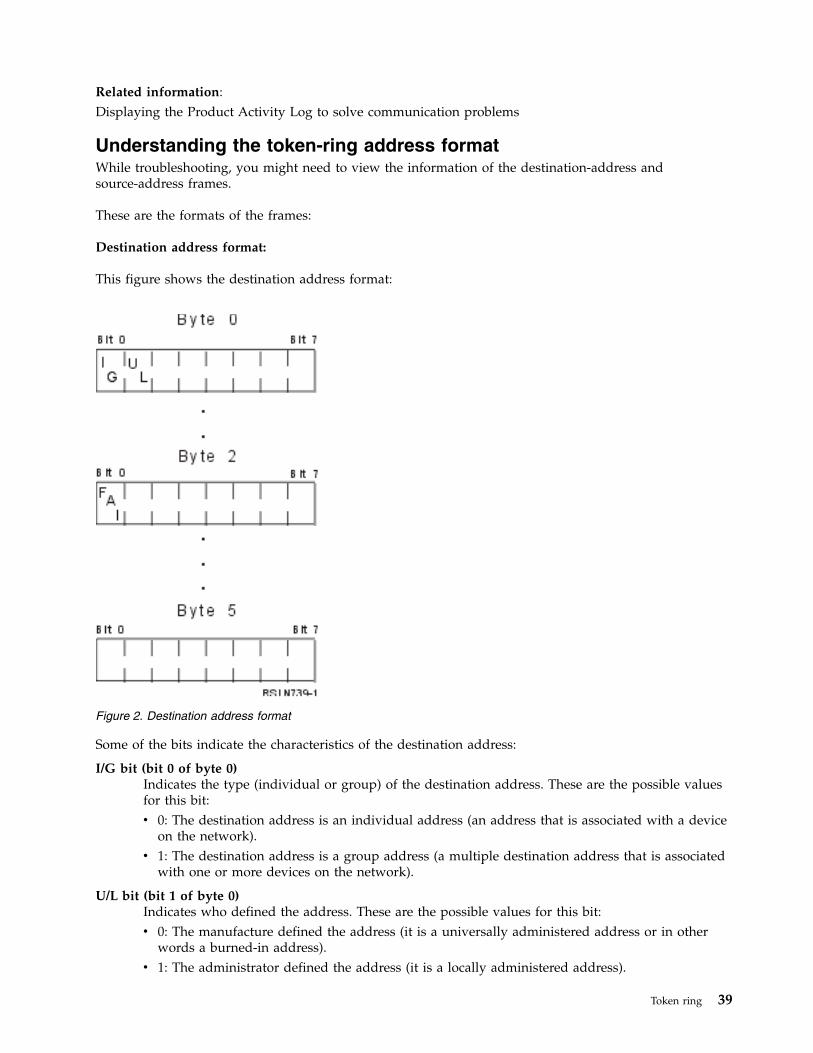
Related information:Displaying the Product Activity Log to solve communication problems
Understanding the token-ring address formatWhile troubleshooting, you might need to view the information of the destination-address andsource-address frames.
These are the formats of the frames:
Destination address format:
This figure shows the destination address format:
Some of the bits indicate the characteristics of the destination address:
I/G bit (bit 0 of byte 0)Indicates the type (individual or group) of the destination address. These are the possible valuesfor this bit:v 0: The destination address is an individual address (an address that is associated with a device
on the network).v 1: The destination address is a group address (a multiple destination address that is associated
with one or more devices on the network).
U/L bit (bit 1 of byte 0)Indicates who defined the address. These are the possible values for this bit:v 0: The manufacture defined the address (it is a universally administered address or in other
words a burned-in address).v 1: The administrator defined the address (it is a locally administered address).
Figure 2. Destination address format
Token ring 39
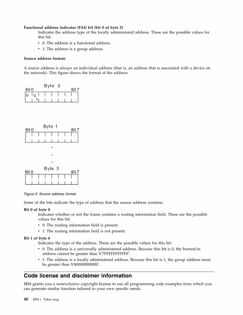
Functional address indicator (FAI) bit (bit 0 of byte 2)Indicates the address type of the locally administered address. These are the possible values forthis bit:v 0: The address is a functional address.v 1: The address is a group address.
Source address format:
A source address is always an individual address (that is, an address that is associated with a device onthe network). This figure shows the format of the address:
Some of the bits indicate the type of address that the source address contains:
Bit 0 of byte 0Indicates whether or not the frame contains a routing information field. These are the possiblevalues for this bit:v 0: The routing information field is present.v 1: The routing information field is not present.
Bit 1 of byte 0Indicates the type of the address. These are the possible values for this bit:v 0: The address is a universally administered address. Because this bit is 0, the burned-in
address cannot be greater than X'7FFFFFFFFFFF'.v 1: The address is a locally administered address. Because this bit is 1, the group address must
be greater than X'800000000000'.
Code license and disclaimer informationIBM grants you a nonexclusive copyright license to use all programming code examples from which youcan generate similar function tailored to your own specific needs.
Figure 3. Source address format
40 IBM i: Token ring

SUBJECT TO ANY STATUTORY WARRANTIES WHICH CANNOT BE EXCLUDED, IBM, ITSPROGRAM DEVELOPERS AND SUPPLIERS MAKE NO WARRANTIES OR CONDITIONS EITHEREXPRESS OR IMPLIED, INCLUDING BUT NOT LIMITED TO, THE IMPLIED WARRANTIES ORCONDITIONS OF MERCHANTABILITY, FITNESS FOR A PARTICULAR PURPOSE, ANDNON-INFRINGEMENT, REGARDING THE PROGRAM OR TECHNICAL SUPPORT, IF ANY.
UNDER NO CIRCUMSTANCES IS IBM, ITS PROGRAM DEVELOPERS OR SUPPLIERS LIABLE FORANY OF THE FOLLOWING, EVEN IF INFORMED OF THEIR POSSIBILITY:1. LOSS OF, OR DAMAGE TO, DATA;2. DIRECT, SPECIAL, INCIDENTAL, OR INDIRECT DAMAGES, OR FOR ANY ECONOMIC
CONSEQUENTIAL DAMAGES; OR3. LOST PROFITS, BUSINESS, REVENUE, GOODWILL, OR ANTICIPATED SAVINGS.
SOME JURISDICTIONS DO NOT ALLOW THE EXCLUSION OR LIMITATION OF DIRECT,INCIDENTAL, OR CONSEQUENTIAL DAMAGES, SO SOME OR ALL OF THE ABOVE LIMITATIONSOR EXCLUSIONS MAY NOT APPLY TO YOU.
Token ring 41

42 IBM i: Token ring
Notices
This information was developed for products and services offered in the U.S.A.
IBM may not offer the products, services, or features discussed in this document in other countries.Consult your local IBM representative for information on the products and services currently available inyour area. Any reference to an IBM product, program, or service is not intended to state or imply thatonly that IBM product, program, or service may be used. Any functionally equivalent product, program,or service that does not infringe any IBM intellectual property right may be used instead. However, it isthe user's responsibility to evaluate and verify the operation of any non-IBM product, program, orservice.
IBM may have patents or pending patent applications covering subject matter described in thisdocument. The furnishing of this document does not grant you any license to these patents. You can sendlicense inquiries, in writing, to:
IBM Director of LicensingIBM CorporationNorth Castle DriveArmonk, NY 10504-1785U.S.A.
For license inquiries regarding double-byte (DBCS) information, contact the IBM Intellectual PropertyDepartment in your country or send inquiries, in writing, to:
Intellectual Property LicensingLegal and Intellectual Property LawIBM Japan Ltd.1623-14, Shimotsuruma, Yamato-shiKanagawa 242-8502 Japan
The following paragraph does not apply to the United Kingdom or any other country where suchprovisions are inconsistent with local law: INTERNATIONAL BUSINESS MACHINES CORPORATIONPROVIDES THIS PUBLICATION "AS IS" WITHOUT WARRANTY OF ANY KIND, EITHER EXPRESS ORIMPLIED, INCLUDING, BUT NOT LIMITED TO, THE IMPLIED WARRANTIES OFNON-INFRINGEMENT, MERCHANTABILITY OR FITNESS FOR A PARTICULAR PURPOSE. Somestates do not allow disclaimer of express or implied warranties in certain transactions, therefore, thisstatement may not apply to you.
This information could include technical inaccuracies or typographical errors. Changes are periodicallymade to the information herein; these changes will be incorporated in new editions of the publication.IBM may make improvements and/or changes in the product(s) and/or the program(s) described in thispublication at any time without notice.
Any references in this information to non-IBM Web sites are provided for convenience only and do not inany manner serve as an endorsement of those Web sites. The materials at those Web sites are not part ofthe materials for this IBM product and use of those Web sites is at your own risk.
IBM may use or distribute any of the information you supply in any way it believes appropriate withoutincurring any obligation to you.
© Copyright IBM Corp. 1998, 2013 43
Licensees of this program who wish to have information about it for the purpose of enabling: (i) theexchange of information between independently created programs and other programs (including thisone) and (ii) the mutual use of the information which has been exchanged, should contact:
IBM CorporationSoftware Interoperability Coordinator, Department YBWA3605 Highway 52 NRochester, MN 55901U.S.A.
Such information may be available, subject to appropriate terms and conditions, including in some cases,payment of a fee.
The licensed program described in this document and all licensed material available for it are providedby IBM under terms of the IBM Customer Agreement, IBM International Program License Agreement orany equivalent agreement between us.
Any performance data contained herein was determined in a controlled environment. Therefore, theresults obtained in other operating environments may vary significantly. Some measurements may havebeen made on development-level systems and there is no guarantee that these measurements will be thesame on generally available systems. Furthermore, some measurements may have been estimated throughextrapolation. Actual results may vary. Users of this document should verify the applicable data for theirspecific environment.
Information concerning non-IBM products was obtained from the suppliers of those products, theirpublished announcements or other publicly available sources. IBM has not tested those products andcannot confirm the accuracy of performance, compatibility or any other claims related to non-IBMproducts. Questions on the capabilities of non-IBM products should be addressed to the suppliers ofthose products.
All statements regarding IBM's future direction or intent are subject to change or withdrawal withoutnotice, and represent goals and objectives only.
COPYRIGHT LICENSE:
This information contains sample application programs in source language, which illustrate programmingtechniques on various operating platforms. You may copy, modify, and distribute these sample programsin any form without payment to IBM, for the purposes of developing, using, marketing or distributingapplication programs conforming to the application programming interface for the operating platform forwhich the sample programs are written. These examples have not been thoroughly tested under allconditions. IBM, therefore, cannot guarantee or imply reliability, serviceability, or function of theseprograms. The sample programs are provided "AS IS", without warranty of any kind. IBM shall not beliable for any damages arising out of your use of the sample programs.
Each copy or any portion of these sample programs or any derivative work, must include a copyrightnotice as follows:
© (your company name) (year). Portions of this code are derived from IBM Corp. Sample Programs.
© Copyright IBM Corp. _enter the year or years_.
If you are viewing this information softcopy, the photographs and color illustrations may not appear.
44 IBM i: Token ring
Programming interface informationThis Token ring publication documents intended Programming Interfaces that allow the customer to writeprograms to obtain the services of IBM i.
TrademarksIBM, the IBM logo, and ibm.com are trademarks or registered trademarks of International BusinessMachines Corp., registered in many jurisdictions worldwide. Other product and service names might betrademarks of IBM or other companies. A current list of IBM trademarks is available on the Web at“Copyright and trademark information” at www.ibm.com/legal/copytrade.shtml.
Adobe, the Adobe logo, PostScript, and the PostScript logo are either registered trademarks or trademarksof Adobe Systems Incorporated in the United States, and/or other countries.
Other product and service names might be trademarks of IBM or other companies.
Terms and conditionsPermissions for the use of these publications is granted subject to the following terms and conditions.
Personal Use: You may reproduce these publications for your personal, noncommercial use provided thatall proprietary notices are preserved. You may not distribute, display or make derivative works of thesepublications, or any portion thereof, without the express consent of IBM.
Commercial Use: You may reproduce, distribute and display these publications solely within yourenterprise provided that all proprietary notices are preserved. You may not make derivative works ofthese publications, or reproduce, distribute or display these publications or any portion thereof outsideyour enterprise, without the express consent of IBM.
Except as expressly granted in this permission, no other permissions, licenses or rights are granted, eitherexpress or implied, to the publications or any information, data, software or other intellectual propertycontained therein.
IBM reserves the right to withdraw the permissions granted herein whenever, in its discretion, the use ofthe publications is detrimental to its interest or, as determined by IBM, the above instructions are notbeing properly followed.
You may not download, export or re-export this information except in full compliance with all applicablelaws and regulations, including all United States export laws and regulations.
IBM MAKES NO GUARANTEE ABOUT THE CONTENT OF THESE PUBLICATIONS. THEPUBLICATIONS ARE PROVIDED "AS-IS" AND WITHOUT WARRANTY OF ANY KIND, EITHEREXPRESSED OR IMPLIED, INCLUDING BUT NOT LIMITED TO IMPLIED WARRANTIES OFMERCHANTABILITY, NON-INFRINGEMENT, AND FITNESS FOR A PARTICULAR PURPOSE.
Notices 45

46 IBM i: Token ring


IBM®
Product Number: 5770-SS1
Printed in USA