ibis.org file · Web viewIBIS Specification Change Template, Rev. 1.2. IBIS Specification Change...
43
IBIS Specification Change Template, Rev. 1.2 BUFFER ISSUE RESOLUTION DOCUMENT (BIRD) BIRD NUMBER: Draft 11 12 13 September November 1030 18 , 2014 ISSUE TITLE: Interconnect Modeling Using IBIS-ISS REQUESTOR: Walter Katz, Signal Integrity Software, Inc. DATE SUBMITTED: {date you sent the original document, for new BIRDs} DATE REVISED: {date(s) you sent any revisions to the document} DATE ACCEPTED BY IBIS OPEN FORUM: { leave blank; for administrative use only} STATEMENT OF THE ISSUE: This BIRD enhances IBIS with interconnect models modeling features to supterminal support Broadband broadband and Coupled coupled package and on-die interconnect using IBIS-ISS and Touchstone models data . ANALYSIS PATH/DATA THAT LED TO SPECIFICATION: Definitions: Enhanced interconnect descriptions in IBIS, called hereinafter “ IBIS Interconnect modeling Models”, makes rely on several assumptions: 1. IBIS Interconnect Models can be described either be using IBIS-ISS subckts subcircuit files or Touchstone Files files 2. If two points in an IBIS Interconnect Model are “Connected”, then there is either a low resistance DC electrical path between the two points, or a small insertion loss at the Nyquist frequency between the two points. 1
-
Upload
phunghuong -
Category
Documents
-
view
220 -
download
0
Transcript of ibis.org file · Web viewIBIS Specification Change Template, Rev. 1.2. IBIS Specification Change...

IBIS Specification Change Template, Rev. 1.2
BUFFER ISSUE RESOLUTION DOCUMENT (BIRD)
BIRD NUMBER: Draft 11 12 13 September November 103018, 2014ISSUE TITLE: Interconnect Modeling Using IBIS-ISSREQUESTOR: Walter Katz, Signal Integrity Software, Inc.
DATE SUBMITTED: {date you sent the original document, for new BIRDs}DATE REVISED: {date(s) you sent any revisions to the document}DATE ACCEPTED BY IBIS OPEN FORUM: {leave blank; for administrative use only}
STATEMENT OF THE ISSUE:
This BIRD enhances IBIS with interconnect models modeling features to supterminal support Broadband broadband and Coupled coupled package and on-die interconnect using IBIS-ISS and Touchstone modelsdata.
ANALYSIS PATH/DATA THAT LED TO SPECIFICATION:
Definitions:
Enhanced interconnect descriptions in IBIS, called hereinafter “IBIS Interconnect modeling Models”, makes rely on several assumptions:
[1.] IBIS Interconnect Models can be described either be using IBIS-ISS subckts subcircuit files or Touchstone Filesfiles
1.[2.] If two points in an IBIS Interconnect Model are “Connected”, then there is either a low resistance DC electrical path between the two points, or a small insertion loss at the Nyquist frequency between the two points.
2.[3.] IBIS Components, and therefore IBIS Interconnect Models, contain terminals consisting of Pins, Die Pads, Buffer I/O Terminals, and Buffer Supply Terminals. Pins are defined under the [Pin] keyword, and may be I/O, POWER, GND, or NC.
3. For each I/O Pin, there is a single Die Pad and single Buffer I/O Terminal associated with it that are “Connected”.
[4.] Under [Pin], fFor each Signal_name associated with Model_name POWER or GND Signal_name, all pinsPins, die Die pads Pads and buffer Buffer supply Supply terminals Terminals that use that Signal_name are “Connected”
[5.] The Terminals (or Terminals) of Interconnect Models are Pins, Die Pads, Buffer I/O Terminals or Buffer supply Supply terminalsTerminals.
1
Author, 01/03/-1,
We should mention the 1:1 pin to pad assumption here. Are we making that assumption for signal paths only or power/gnd paths also?
Author, 01/03/-1,
... to each other and to the I/O Pin?
Author, 01/03/-1,
A tree diagram, preferably a vertical one, would be very handy here.
Author, 01/03/-1,
Let’s define “point” and “node” as synonymous.
Author, 01/03/-1,
Are the IBIS-ISS subcircuits only to be included in separate files? What is the relationship to BIRD125.1? Proposal: no inline Touchstone or IBIS-ISS subcircuits; everything shall be in separate files.

IBIS Specification Change Template, Rev. 1.2
[6.] There is an implicit assumptionIBIS assumes that one each I/O pin [Pin] is connected to one Die Pad and is connected to a one bufferBuffer I/O Terminal. Two differential I/O pins mustshall be connected to two differential die pads and either two single ended buffer Buffer I/O Terminals or a single true differential buffer Buffer I/O Terminal.
[7.] If mthere are joins, (defined as multiple buffer Buffer Terminals (Supply or I/O) are connected to a single pin) , then EMD should shall be used for the interconnect description EMD ….
4.[8.] An Interconnect Model may represent a single connection between Pins and Buffer Terminals (Supply and I/O), Pins and Die Pads, or Die Pads and Buffer Terminals (Supply and I/O). An Interconnect Model may also represent multiple connections between multiple Pins and multiple Buffer Terminals (Supply and I/O), multiple Pins and multiple Die Pads, or multiple Die Pads and multiple Buffer Terminals (Supply and I/O).
ANY OTHER BACKGROUND INFORMATION:
{These documents will be archived, so use this section to add any detail that is not part of the section above or the changed text itself , but should not be lost.}
2
Terminals
Pins
I/O
POWER
GND
NC
Die Pads Buffer Terminals
Buffer I/O Terminal
Buffer Supply Terminal
Author, 01/03/-1,
This is to distinguish from Define Package which is limited to single I/O interconnect models and does not support differentials
Author, 01/03/-1,
This seems to say the same thing for single and multiple connections. What is the difference? Also make sure this is not confused with the 1:1 mapping between pins and pads.
Author, 01/03/-1,
Are there buffers, from an interconnect perspective, or just Buffer Terminals?

IBIS Specification Change Template, Rev. 1.2
The following keywords should be added as their own Chapter. The current Chapter 7 should be modified with the existing text placed in a sub-section called “[PACKAGE MODEL]”._________________________________________________________________________7 PACKAGE MODELINGSeveral types of package modeling formats are available in IBIS. These include:
1. Lumped [Component]-level models for the entire [Component], using the [Package] keyword
2. Lumped [Component]-level modeling per-pin, using the [Pin] keyword3. [Package Model] (including [Alternate Package Models] and [Define Package Model])4. Interconnect Model Selectors
The lumped formats are described in the [Package] and [Pin] keyword defintions above. The [Package Model] format is described in this chapter, while Interconnect Model Selectors are described in Chapter 13.The order of precedence between the various formats is described in Chapter 12, “Rules of Precedence”. …________________________________________________________________________13 INTERCONNECT MODEL SELECTORSThis chapter defines an advanced format for interconnect descriptions that may be used for packages as well as other types of interconnect between buffer models and pins, for signal and power path modeling purposes.
Keyword: [Interconnect Model Selector]Required: NoDescription: Used to list available interconnect models pick select an a specific interconnect model for this the component.Usage Rules: Interconnect Models are described by IBIS-ISS subckts or ToucshstoneTouchstone files that are between the Pins, Die Pads and Buffer Terminals (Supply and I/O) of a Component.A component may have none, one or more than one [Interconnect Model] associated with it. If there are any [Interconnect Model]s exist for the Component, they mustshall be listed in this section. The section under the [Interconnect Model Selector] keyword mustshall have two fields per line, with each line defining the Interconnect Models associated with the Component. The fields mustshall be separated by at least one white space. The first field lists the [Interconnect Model] name (up to 40 characters long). The second field is the name of the file containing the [Interconnect Model]. If the [Interconnect Model] is in this IBIS file, then the second field mustshall be “*”. The first entry under the [Interconnect Model Selector] keyword shall be considered the default by the EDA tool. Each Interconnect Model name may only appear once under the [Interconnect Model Selector] keyword for a given Component.
3
Author, 01/03/-1,
We should try to make this more consistent with the [Alternate Package Models] keyword.
Author, 01/03/-1,
This assumes in-line IBIS-ISS and Touchstone data is permitted.
Author, 01/03/-1,
How long?
Author, 01/03/-1,
If there is only one [Interconnect Model] there is no need for a selector. “If there are any” includes one, so this doesn’t make sense.
Author, 01/03/-1,
We should have an “End” version of each keyword to make parsing and scopig easier.

IBIS Specification Change Template, Rev. 1.2
Example:[Interconnect Model Selector] QS-SMT-cer-8-pin-pkgs_iss * QS-SMT-cer-8-pin-pkgs_sNp QS-SMT-cer-8-pin-pkgs_sNp.ipkg[End Interconnect Model Selector]
Keyword: [Interconnect Model]Required: NoDescription: Marks the beginning of an interconnect model description.Usage Rules: The length of the interconnect model name mustshall not exceed 40 characters in length. Blank characters are not allowed. Example:[Interconnect Model] QS-SMT-cer-8-pin-pkgs_iss
Keyword: [Manufacturer] Allow or RequireKeyword: [Description] Allow or RequireSame requirements as in IBIS if separate file.
Keyword: [Begin Interconnect Model] <Interconnect Model Name>Subparameter: File_TS Typ_File Min_File Max_File Subparameter: File_ISS Typ|Min|Max File_Name Circuit_NameSubparameter: Param <name> Typ_Value Min_Value Max_Value
Subparameter: Unused_Terminal_Termination <resistance> Subparameter: Number_of_Terminals <# terminals> | Made into a SubparameterSubparameter: Terminal Terminal_number Location ID {Qualifiers}Keyword: [End Interconnect Model] The following subparameters are defined:
LanguageParamFile_TSFile_ISSUnused_Terminal_TerminationNumber_of_TerminalsTerminal
Unless noted below, no subparameter requires the presence of any other subparameter and e. Each subparameter is optional.
Language rules:
Unused_Terminal_Termination rules:This subparameter defines the termination that is to be applied to the Terminals of a subckt or Touchstone file that are not being used in each [Begin Interconnect Model]/[End Interconnect
4
Author, 01/03/-1,
This section is totally incorrect and does not reflect the changes made below
Author, 01/03/-1,
This is too confusing with the previous keyword being [Interconnect Model] These keyword names should be more distinct than this.

IBIS Specification Change Template, Rev. 1.2
Model] group. The subparameter name is followed by a single integer argument greater than zero on the same line, separated from the subparameter name by whitespace.If this subparameter is present, the EDA should connect the unused Terminals to GND through a resistor with the value of resistance in ohms provided in the argument. If this parameter is not defined and if Language is IBIS-ISS, then the EDA tool should connect the unused Terminals to GND through a 1 Meg ohm resistor. If Language is Touchstone, then the EDA tool should connect the unused Terminals to GND through a resistor with the Touchstone File reference resistance of the Terminal.
Only one Unused_Terminal_Termination subparameter may appear for a given [Begin Interconnect Model] keyword.
Number_of_Terminals rules: The Number_of_Terminals subparameter is required and defines the number of terminals associated with the Interconnect Model. The subparameter name is followed by a single integer argument greater than zero on the same line, separated from the subparameter name by whitespace. Only one Number_of_Terminals subparameter may appear for a given [Begin Interconnect Model] keyword.
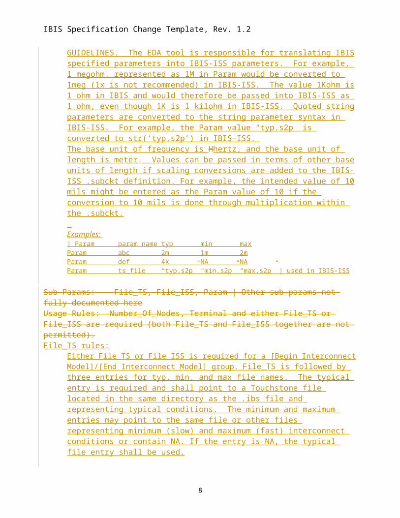
Param rules:The subparameter Param is optional and only legal for File_ISS references. Param shall be followed by a string argument and threefour arguments: a string argument, param_name, which is the name of the parameter to be passed into the IBIS-ISS; and three numerical values or three string values (surrounded by double quotes) located in the typ, min, and max columns. Several Param lines are permitted as long as each of the param_name entries is unique within that [Begin Model Interconnect] keyword. Each Param line shall have a typ entry. Either or both the min and max entries may be NA, in which cases the typ entry is used. The typ, min, and max parameters are, by default, associated with the corner_name Typ, Min, and Max files and their corresponding circuit_names. However, the EDA tool is expected to support passing any of the Param typ, min, or max values, as selected by the User or EDA tool, into any File_ISS corner_name file. The Param values associated with any param_name shall all be numerical or all string values (or NA). If possible, the Param min and max values should represent slow and fast interconnect conditions. Because of parameter interactions, this may not always be possible.Other Notes: The numerical value rules follow the scaling conventions in Section 3, GENERAL SYNTAX RULES AND GUIDELINES. The EDA tool is responsible for translating IBIS specified parameters into IBIS-ISS parameters. For example, 1 megohm, represented as 1M in Param would be converted to 1meg (1x is not recommended) in IBIS-ISS. The value 1Kohm is 1 ohm in IBIS and would therefore be passed into IBIS-ISS as 1 ohm, even though 1K is 1 kilohm in IBIS-ISS. Quoted string parameters are converted to the string parameter syntax in IBIS-ISS. For example, the Param value “typ.s2p” is converted to str(‘typ.s2p’) in IBIS-ISS. The base unit of frequency is Hhertz, and the base unit of length is meter. Values can be passed in terms of other base units of length if scaling conversions are added to the IBIS-ISS .subckt definition. For example, the intended value of 10 mils might be entered as the
5
Author, 01/03/-1,
This is really not done on the subckt definition, it might be supplied by the model author inside the subcircuit.
Author, 01/03/-1,
I would use different words. Saying “1Kohm is” makes it sound like that IBIS-ISS doesn’t understand “1kOhm” or “1kohm”, which I believe it does because it is case insensitive.I wouldl also watch out for spelling, there are no such things as kilohm or megohm, as far as I can tell and I would encourage proper spelling of the scaling factors by recommending the correct cases in the discussion and exaples.
Author, 01/03/-1,
I would copy the [External ***] parameter syntax here too. W ewill have to be careful about establishing “local rues” here for typ/min/max. It is not a good practice to have different rules on that for each keyword…
Author, 01/03/-1,
Yes
Author, 01/03/-1,
Please use the correct spelling for this
Author, 01/03/-1,
Are we allowing only one Touchstone or ISS model within these keyword pairs? If not, what if one needs a certain value, and another needs a different value? Also the wording of this sentence is not so good, because it seems to say unused subcircuit or Touchstone file, instead of unused terminal…

IBIS Specification Change Template, Rev. 1.2
Param value of 10 if the conversion to 10 mils is done through multiplication within the .subckt. Examples: | Param param_name typ min maxParam abc 2m 1m 2mParam def 4k NA NAParam ts_file “typ.s2p” “min.s2p” “max.s2p” | used in IBIS-ISS
Sub-Params: File_TS, File_ISS, Param | Other sub-params not fully documented hereUsage Rules: Number_Of_Nodes, Terminal and either File_TS or File_ISS are required (both File_TS and File_ISS together are not permitted).File_TS rules:
Either File_TS or File_ISS is required for a [Begin Interconnect Model]/[End Interconnect Model] group. File_TS is followed by three entries for typ, min, and max file names. The typical entry is required and shall point to a Touchstone file located in the same directory as the .ibs file and representing typical conditions. The minimum and maximum entries may point to the same file or other files representing minimum (slow) and maximum (fast) interconnect conditions or contain NA. If the entry is NA, the typical file entry shall be used.
Example: | file_type typ min maxFile_TS typ.s8p min.s8p max.s8p
or| file_type typ min maxFile_TS typ.s4p min.s4p NA
File_ISS rules:Either File_TS or File_ISS is required for a [Begin Interconnect Model]/[End Interconnect Model] group. The File_ISS subparameter is followed by three string arguments consisting of corner_name, file_name, and circuit_name (.subckt name) for that file and located in the same directory as the .ibs file. The corner_name shall be Typ, Min, or Max. File_ISS for the Typ corner_name is required, and File_ISS for the Min and Max corner_names are optional. If present, each File_ISS shall have a unique corner_name. If File_ISS for either the Min or Max corner_name is missing, the File_ISS for the Typ corner_name shall be used to describe the missing corner_name file reference. The Min and Max file_names should represent slow and fast interconnect conditions.
Example: | file_type corner_name file_name circuit_name (.subckt name)File_ISS Typ net.iss netlist_typFile_ISS Min net.iss netlist_min | in same file as net.spFile_ISS Max net_max.iss netlist_max | in separate file
Terminal rules:
6
Author, 01/03/-1,
Yes
Author, 01/03/-1,
This doesn’t match the text above, but this is what I had in mind…
Author, 01/03/-1,
Can we get more than three corners? Is this speed, or impedance, or something else?
Author, 01/03/-1,
Same comment as above. This is even more similar to [External ***]…
Author, 01/03/-1,
Can we get more than three corners? Is this speed, or impedance, or something else?
Author, 01/03/-1,
Can we get more than three corners?
Author, 01/03/-1,
We might want to put these on separate lines, like it is done for [External ***]. That would allow us later to add more corner variants if desired, and reduce the issues with long files names and the line length… It would also be more consistent with the rest of the spec., even if you hate those keywords…
Author, 01/03/-1,
So what is the name of the keyword? This seems to be the 3rd variant I read so far. [Interconnect Model], [Begin Interconnect Mdoel], [Begin Model]?
Author, 01/03/-1,
I blindly copied and pasted the suggestions from Bob. These need to be carefully reviewed with him.
Author, 01/03/-1,
Subparameters of which keyword? The last keyword I see above this is [End Interconnect Model], and “end” keywords usually have no subparameters…
Author, 01/03/-1,
So how would we distinguish between 2 meters and 2 millimeters (2m, or 2mm)if this was a length for a W-element? I know we can write 2 for meters and 2m for millimeters, but what if someone wants to write the unit meter to make sure people know it is not something else?

IBIS Specification Change Template, Rev. 1.2
One or more Terminal subparameters may appear under a given [Begin Interconnect Model] keyword. At least one Terminal subparameter is required. Each Terminal record contains information on a terminal of an IBIS-ISS subckt (or Touchstone file).
The Terminal subparameter is followed by three arguments: Terminal_number, Terminal_ID and Terminal_Location Terminal_number shall be a positive non-zero integer and less than or equal to the number of terminals in the Number_of_Terminals argument. The same Terminal_number shall not appear more than once for a given Interconnect Model. If any Terminals are not present for a given Interconnect Model, then those terminals are unused, and shall be terminated according to the Unused_Terminal_Termination_ Rules.
Terminal_ID is a string using either a [Pin] name, a Signal_name, a Model_name, or “Default”.
Terminal_Location is a string, and shall have one of the values Pin, Pad, Buf, Pin_Sig, Pad_Sig, Buf_Sig, Buf_PURef, Buf_PDRef, Buf_PCRef, Buf_GCRef or Buf_XRef.
Pin indicates this terminal connected to a specific pin, Terminal_ID shall be a Pin_name, Model_name or Default.
Pad indicates this terminal connected to a specific die pad, Terminal_ID shall be a Pin_name, Model_name or Default.
Buf indicates this terminal connected to a specific buffer model I/O or signal terminal, Terminal_ID shall be a Pin_name, Model_name or Default.
Pin_Sig indicates that this terminal is connected to all pins that have Signal_name Terminal_ID. Terminal_ID shall be a Signal_name on a Pin that has Model_name Power or GND. All pins that have Signal_name Terminal_ID are considered shorted together at the pin side of the package model.
Pad_Sig indicates that this terminal is connected to all die pads that have Signal_name Terminal_ID. Terminal_ID shall be a Signal_name on a Pin that has Model_name Power or GND. All die pads that have Signal_name Terminal_IDs are considered shorted together at the die pad side of the package model.
Buf_Sig indicates that this terminal is connected to all buffer model terminals Pullup Reference, Power Reference, Power Clamp Reference, Ground Clamp Reference or External Reference that have an Terminal_ID containing a Signal_name Terminal_ID shall be a Signal_name on a Pin that has Model_name Power or GND. All Buffer Terminals that have Signal_name Terminal_ID are considered shorted together at the buffer side of the package model.
Buf_PURef indicates this terminal connected to a specific buffer model pullup reference, Terminal_ID shall be a Pin_name, Model_name or Default.
Buf_PDRef indicates this terminal connected to a specific buffer model pulldown reference, Terminal_ID shall be a Pin_name, Model_name or Default.
Buf_PCRef indicates this terminal connected to a specific buffer model power clamp reference, Terminal_ID shall be a Pin_name, Model_name or Default.
Buf_GCRef indicates this terminal connected to a specific buffer model ground clamp reference, Terminal_ID shall be a Pin_name, Model_name or Default.
Buf_XRef indicates this terminal connected to a specific buffer model external reference, Terminal_ID shall be a Pin_name, Model_name or Default.
ID shall be a Pin_name, Signal_name, Model_name or Default.
7
Author, 01/03/-1,
Let’s be consistent with the spelling of similar reserved node names used for the [Esternal ***] keywords, such as “_puref” and “_pdref”, etc…
IBIS Specification Change Template, Rev. 1.2
Qualifiers may have the values Aggressor, Model_name, Default, Inverting, Non-Inverting and Connection(n). Qualifiers are optional, there may be zero, one or several qualifiers on each Terminal record. Qualifiers may appear in any order.
Aggressor, any Terminal may have the qualifier aggressor. It means that terminal does not have coupling from all aggressor sources, so can be treated as an aggressor and should not be treated as a victim. By default a connection is a Victim.
Model_name, means that the ID Terminal_ID on this terminal is a Model_name Default, means that the ID Terminal_ID on this terminal shall be Default. A terminal cannot have both Default and Model_name qualifiers. If a terminal is either qualifier Default or Model_name then the terminal is considered a
“Pre-Layout” terminal. If a “Pre-Layout” terminal is connected to a differential model, then the terminal shall
have either the Inverting or Non-Inverting qualifier. All terminals that have the same Connection(n) (where n is a positive integer) are
electrically connected. A single ended connection will have two terminals with Connection(n). A differential connection will have four terminals with Connection(n).` Connection(n) qualifiers are required if there are two or more Pre-Layout connections. Is a differential one connection or two connections (clarify).
Special differential rules for Pullup Reference, Power Reference, Power Clamp Reference, Ground Clamp Reference and External Reference.
o There can be only one terminal for each Pullup Reference, Power Reference, Power Clamp Reference, Ground Clamp Reference and External Reference on a true differential [External Model]. These can be referenced by either the Non-Inverting or Inverting Pin_name.
o There may be only one terminal for each Pullup Reference, Power Reference, Power Clamp Reference, Ground Clamp Reference and External Reference for each side of a legacy differential model that consists of two independent single ended models. These can be referenced by either the Non-Inverting or Inverting Pin_name.
o There may be two terminals for each Pullup Reference, Power Reference, Power Clamp Reference, Ground Clamp Reference and External Reference for each side of a legacy differential model that consists of two independent single ended models.
Other Notes:More than one [Interconnect Model] may be available for a specific simulation. The EDA tool may choose any of the available models but, in general, should prefer a model that matches by Pin_name, then Model_name and finally Default.
An Interconnect Model with File_TS with N Ports. N is either determined from the N in the .sNp file name extension for a Touchstone I file or from the [Number of Ports] record in a Touchstone II file. The [Number of Terminals] in the Interconnect Model shall be N+1. The Terminal Rules is described below:
[o The EDA tool shall use the Pin_name or Signal_name specified in the Terminal
“N+1” record as the reference node for each of the N ports.o Terminal/Port Mapping
Terminal Port
8
Author, 01/03/-1,
What is the definition of “record”? Is it one line (below) or the entire table?
Author, 01/03/-1,
I would combine these last two bullets into one
Author, 01/03/-1,
I would put the word “signal” between those two words.here too.
Author, 01/03/-1,
I would put the word “signal” between those two words.
Author, 01/03/-1,
This is confusing with the differential case, because it could imply that the diff pair is shorted together…
Author, 01/03/-1,
This really doesn’t tell me what “default” actually means…

IBIS Specification Change Template, Rev. 1.2
1 1 2 2 … N N N+1 reference
o If a Port is not connected, then it shall be terminated with a resistor to the node on Terminal N+1. The resistance shall be the Port Reference Impedance.
o It shall be an error if Terminal N+1 is not specified to a Pin, Pad, or Buffer that is not on a connection to a Signal_name that is POWER or GND
Examples:
9
Author, 01/03/-1,
What? (English)…
Author, 01/03/-1,
By whom? The model maker or the EDA tool?

IBIS Specification Change Template, Rev. 1.2
IBIS File[Pin] signal_name model_name R_pin L_pin C_pinA1 DQ1 DQ A2 DQ2 DQA3 DQ3 DQD1 DQS DQSD2 DQS DQSP1 VDD POWERP2 VDD POWERP3 VDD POWERP4 VDD POWERP5 VDD POWERG1 VSS GNDG2 VSS GNDG3 VSS GNDG4 VSS GND [Diff Pin] inv_pin vdiff tdelay_typ tdelay_min tdelay_maxD1 D2 NA NA NA NA[Die Supply Pads] VDD1 VDDVDD2 VDDVDD3 VDDVSS1 VSSVSS2 VSS[Pin Mapping] pulldown_ref pullup_ref gnd_clamp_ref power_clamp_ref ext_refA1 VSS VDD NC NC NC A2 VSS VDD NC NC NCA3 VSS VDD NC NC NCD1 VSS VDD NC NC NCD2 VSS VDD NC NC NC
• Single DQ (A1)– Terminal 1 Pin A1– Terminal 2 Buf A1
• Single DQS | There is a [Diff Pin] record “D1 D2 …”– Terminal 1 Pin D1– Terminal 2 Pin D2– Terminal 3 Buf D1– Terminal 4 Buf D2
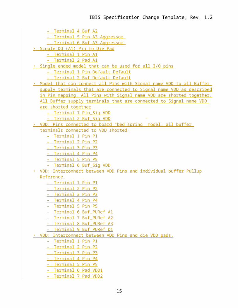
• One DQ (A2) victim, two DQ (A1 and A3) aggressors– Terminal 1 Pin A1 Aggressor – Terminal 2 Buf A1 Aggressor – Terminal 3 Pin A2– Terminal 4 Buf A2– Terminal 5 Pin A3 Aggressor – Terminal 6 Buf A3 Aggressor
• Single DQ (A1) Pin to Die Pad– Terminal 1 Pin A1– Terminal 2 Pad A1
• Single ended model that can be used for all I/O pins
10

IBIS Specification Change Template, Rev. 1.2
– Terminal 1 Pin Default Default– Terminal 2 Buf Default Default
• Model that can connect all Pins with Signal_name VDD to all Buffer supply terminals that are connected to Signal_name VDD as described in Pin_mapping. All Pins with Signal_name VDD are shorted together. All Buffer supply terminals that are connected to Signal_name VDD are shorted together
– Terminal 1 Pin_Sig VDD– Terminal 2 Buf_Sig VDD
• VDD: Pins connected to board “bed spring” model, all buffer terminals connected to VDD shorted
– Terminal 1 Pin P1– Terminal 2 Pin P2– Terminal 3 Pin P3– Terminal 4 Pin P4– Terminal 5 Pin P5– Terminal 6 Buf_Sig VDD
• VDD: Interconnect between VDD Pins and individual buffer Pullup Reference.
– Terminal 1 Pin P1– Terminal 2 Pin P2– Terminal 3 Pin P3– Terminal 4 Pin P4– Terminal 5 Pin P5– Terminal 6 Buf_PURef A1– Terminal 7 Buf_PURef A2– Terminal 8 Buf_PURef A3– Terminal 9 Buf_PURef D1
• VDD: Interconnect between VDD Pins and die VDD pads.– Terminal 1 Pin P1– Terminal 2 Pin P2– Terminal 3 Pin P3– Terminal 4 Pin P4– Terminal 5 Pin P5– Terminal 6 Pad VDD1– Terminal 7 Pad VDD2– Terminal 8 Pad VDD3
• VDD: Interconnect between die VDD pads and individual buffer Pullup Reference.
– Terminal 1 Pad VDD1– Terminal 2 Pad VDD2– Terminal 3 Pad VDD3– Terminal 4 Buf_PURef A1– Terminal 5 Buf_PURef A2– Terminal 6 Buf_PURef A3– Terminal 7 Buf_PURef D1
• Single DQ– Terminal 1 Pin DQ Model_name
11
Author, 01/03/-1,
How do you know which of these VDDx die pads belog to which [Model]’s upref terminal? I don’t see a way to trace that with this syntax.
Author, 01/03/-1,
This has to be reviewed carefully, because the [Pin Mapping] keyword doesn’t “observe” the 2nd column of the [Pin] keyword to make the connections on the pin side. As a consequence this “Terminal” syntax may have conflicts with [Pin Mapping] as writte here. I can see ways to make this work without such conflicts, but we need to discuss it and agree on it.

IBIS Specification Change Template, Rev. 1.2
– Terminal 2 Buf DQ Model_name• Single DQS
– Terminal 1 Pin DQS Model_name Non-Inverting – Terminal 2 Pin DQS Model_name Inverting– Terminal 3 Buf DQS Model_name Non-Inverting– Terminal 4 Buf DQS Model_name Inverting
• Single DQ victim, two DQ aggressors– Terminal 1 Pin DQ Model_name Aggressor Connection(1) – Terminal 2 Buf DQ Model_name Aggressor Connection(1)– Terminal 3 Pin DQ Model_name Connection(2)– Terminal 4 Buf DQ Model_name Connection(2)– Terminal 5 Pin DQ Model_name Aggressor Connection(3) – Terminal 6 Buf DQ Model_name Aggressor Connection(3)
• One DQ victim, two DQ aggressors, one DQS aggressor– Terminal 1 Pin DQ Model_name Aggressor Connection(1) – Terminal 2 Buf DQ Model_name Aggressor Connection(1)– Terminal 3 Pin A2– Terminal 4 Buf A2– Terminal 5 Pin DQ Model_name Aggressor Connection(2) – Terminal 6 Buf DQ Model_name Aggressor Connection(2)– Terminal 7 Pin DQS Model_name Aggressor Connection(3) Non-
Inverting – Terminal 8 Buf DQS Model_name Aggressor Connection(3)
Inverting– Terminal 9 Pin DQS Model_name Aggressor Connection(3)
Non-Inverting – Terminal 10 Buf DQS Model_name Aggressor Connection(3)
Inverting• One single ended victim, two single ended aggressors, one
differential aggressor– Terminal 1 Pin Default Default Aggressor Connection(1) – Terminal 2 Buf Default Default Aggressor Connection(1)– Terminal 3 Pin Default Default– Terminal 4 Buf Default Default – Terminal 5 Pin Default Default Aggressor Connection(2) – Terminal 6 Buf Default Default Aggressor Connection(2)– Terminal 7 Pin Default Default Aggressor Connection(3) Non-
Inverting – Terminal 8 Buf Default Default Aggressor Connection(3)
Inverting– Terminal 9 Pin Default Default Aggressor Connection(3)
Non-Inverting – Terminal 10 Buf Default Model_name Aggressor
Connection(3) Inverting
12
Author, 01/03/-1,
Is this a practical case? I don’t see how a user would be able to assign buffer models to this, or this to buffer models…

IBIS Specification Change Template, Rev. 1.2
13

IBIS Specification Change Template, Rev. 1.2
14
IBIS Specification Change Template, Rev. 1.2
Keyword: [End Interconnect Model]Required: Yes, to end the [Begin Interconnect Model] keywordDescription: Indicates the end of the interconnect model data. Other Notes: In between the [Begin Interconnect Model] and [End Interconnect Model] keywords is the package model data itself. The data is any number of interfaces to either IBIS-ISS models or Touchstone files.Example: [End Interconnect Model]
We need a careful discussion on how Pin Mapping is used in conjunction with Terminals that have Signal_name. (MM)
We need a carefull discussion on when package models are Pre-Layout only. (Walter)
We need a carefull discussion on precedence rules if more than one model can be used to represent interconnect. (Walter)
Interaction with Circuit Call and External Circuit? (Mutually Exclusive)
Interaction with Define Package Model, or are they mutually exclusive.Precedence Rules? Both allowed in a component but only one type can be used.
15
Author, 01/03/-1,
Plus the [Package] and [Pin] keyword based package models.
Author, 01/03/-1,
Are you referring to legacy package models together with this new package/interconnect model, or multiple new package/interconnect models?
Author, 01/03/-1,
Duplicate, please remove

IBIS Specification Change Template, Rev. 1.2
Sub-Params: File_TS, File_ISS, Param | Other sub-params not fully documented hereUsage Rules: Number_Of_Nodes, Terminal and either File_TS or File_ISS are required (both File_TS and File_ISS together are not permitted).
For referencing Touchstone files:
Subparameter: File_TS Typ_File Min_File Max_FileRequired: Either File_TS or File_ISS is required for a [Begin ModelBegin Interconnect Model]/[End ModelEnd Interconnect Model] groupDescription: File_TS is followed by three entries for typ, min, and max file names. The typical entry is required and mustshall point to a Touchstone file located in the same directory as the .ibs file and representing typical conditions. The minimum and maximum entries may point to the same file or other files representing minimum (slow) and maximum (fast) interconnect conditions or contain NA. If the entry is NA, the typical file entry shall be used.
Example: | file_type typ min maxFile_TS typ.s8p min.s8p max.s8p
or| file_type typ min maxFile_TS typ.s4p min.s4p NA
For referencing IBIS-ISS files:
Subparameter: File_ISS Typ|Min|Max File_Name Circuit_NameRequired: Either File_TS or File_ISS is required for a [Begin ModelBegin Interconnect Model]/[End ModelEnd Interconnect Model] groupDescription: File_ISS is followed by three entries consisting of corner_name, file_name, and circuit_name (.subckt name) for that file and located in the same directory as the .ibs file. The corner_name shall be Typ, Min, or Max. File_ISS for the Typ corner_name is required, and File_ISS for the Min and Max corner_names are optional. If present, each File_ISS mustshall have a unique corner_name. If File_ISS for either the Min or Max corner_name is missing, the File_ISS for the Typ corner_name shall be used to describe the missing corner_name file reference. The Min and Max file_names should represent slow and fast interconnect conditions.
Example: | file_type corner_name file_name circuit_name (.subckt name)File_ISS Typ net.iss netlist_typFile_ISS Min net.iss netlist_min | in same file as net.spFile_ISS Max net_max.iss netlist_max | in separate file
Subparameter: Param <name> Typ_Value Min_Value Max_Value Required: No, but legal only if Language is IBIS-ISS.Description:
16
Author, 01/03/-1,
This doesn’t match the text above, but this is what I had in mind…
Author, 01/03/-1,
Can we get more than three corners? Is this speed, or impedance, or something else?
Author, 01/03/-1,
Same comment as above. This is even more similar to [External ***]…
Author, 01/03/-1,
Can we get more than three corners? Is this speed, or impedance, or something else?
Author, 01/03/-1,
Can we get more than three corners?
Author, 01/03/-1,
We might want to put these on separate lines, like it is done for [External ***]. That would allow us later to add more corner variants if desired, and reduce the issues with long files names and the line length… It would also be more consistent with the rest of the spec., even if you hate those keywords…
Author, 01/03/-1,
So what is the name of the keyword? This seems to be the 3rd variant I read so far. [Interconnect Model], [Begin Interconnect Mdoel], [Begin Model]?
Author, 01/03/-1,
I blindly copied and pasted the suggestions from Bob. These need to be carefully reviewed with him.
Author, 01/03/-1,
Subparameters of which keyword? The last keyword I see above this is [End Interconnect Model], and “end” keywords usually have no subparameters…

IBIS Specification Change Template, Rev. 1.2
The subparameter Param is optional and only legal for File_ISS references. Param shall be followed by a param_name of the parameter to be passed into the IBIS-ISS and its numerical values or a string values (surrounded by double quotes) located in the typ, min, and max columns. Several Param lines are permitted as long as each of the param_name entries is distinct. Each Param line shall have a typ entry. Either or both the min and max entries can be NA, in which cases the typ entry is used. The typ, min, and max parameters are, by default, associated with the corner_name Typ, Min, and Max files and their corresponding circuit_names. However, the EDA tool is expected to support passing any of the Param typ, min, or max values, as selected by the User or EDA tool, into any File_ISS corner_name file. The Param values associated with any param_name mustshall all be numerical or all string values (or NA). If possible, the Param min and max values should represent slow and fast interconnect conditions. Because of parameter interactions, this may not always be possible.Other Notes: The numerical value rules follow the scaling conventions in Section 3, GENERAL SYNTAX RULES AND GUIDELINES. The EDA tool is responsible for translating IBIS specified parameters into IBIS-ISS parameters. For example, 1 megohm, represented as 1M in Param would be converted to 1meg (1x is not recommended) in IBIS-ISS. The value 1Kohm is 1 ohm in IBIS and would therefore be passed into IBIS-ISS as 1 ohm, even though 1K is 1 kilohm in IBIS-ISS. Quoted string parameters are converted to the string parameter syntax in IBIS-ISS. For example, the Param value “typ.s2p” is converted to str(‘typ.s2p’) in IBIS-ISS. The base unit of frequency is Hertz, and the base unit of length is meter. Values can be passed in terms of other base units of length if scaling conversions are added to the IBIS-ISS .subckt definition. For example, the intended value of 10 mils might be entered as the Param value of 10 if the conversion to 10 mils is done through multiplication within the .subckt. Examples: | Param param_name typ min maxParam abc 2m 1m 2mParam def 4k NA NAParam ts_file “typ.s2p” “min.s2p” “max.s2p” | used in IBIS-ISS
NOTES AND QUESTIONSSource Touchstone | IBIS-ISS is not necessary since the file format is recognized by File_TS or File_ISS. File_ISS captures both the file_name and circuit_name for each corner.For File_ISS, an alternative syntax could have been File_ISS_Typ, File_ISS_Min, File_ISS_Max to eliminate the corner_name column, where only File_ISS_Typ is required for file references to IBIS-ISS.Parameter is shorted to Param (.param is legal in IBIS-ISS) to differentiate it further from Parameters in the multi-lingual syntax. ( (Parameter has several meanings in IBIS/IBIS- and the AMIAlgorithmic Modeling Interface.)File_names are not quoted to be consistent with Corner in the multi-lingual syntax.For File_TS, all columns typ, min, and max are entered (or NA for either or both min and max) to follow the corner syntax convention used for most IBIS keywords and subparameters. The typ entry is required, and the typ entry value is used by the EDA tool for any NA entry. The same typ, min, max convention is used for the subparameter Param.Entries for strings in Param are surrounded by double quotes to be consistent with string_literal Parameters in the multi-lingual syntax (or where the AMI string_literal parameter surrounded by double quotes is passed into the multi-lingual Parameters
17
Author, 01/03/-1,
That may work for numbers, but not so much for file names, which can be arbitrarily(?) long. I would keep all file name syntax the same as far as possible.
Author, 01/03/-1,
Which is this differentiation necessary? Is there a technical reason? Any inconsistency makes it harder on the parser developer, and the model maker too…
Author, 01/03/-1,
Let’s try to be consistent with other existing keywords in the spec., as long as we are not running into technical limitations.
Author, 01/03/-1,
So how would we distinguish between 2 meters and 2 millimeters (2m, or 2mm)if this was a length for a W-element? I know we can write 2 for meters and 2m for millimeters, but what if someone wants to write the unit meter to make sure people know it is not something else?
Author, 01/03/-1,
This is really not done on the subckt definition, it might be supplied by the model author inside the subcircuit.
Author, 01/03/-1,
I would use different words. Saying “1Kohm is” makes it sound like that IBIS-ISS doesn’t understand “1kOhm” or “1kohm”, which I believe it does because it is case insensitive.I wouldl also watch out for spelling, there are no such things as kilohm or megohm, as far as I can tell and I would encourage proper spelling of the scaling factors by recommending the correct cases in the discussion and exaples.
Author, 01/03/-1,
I would copy the [External ***] parameter syntax here too. W ewill have to be careful about establishing “local rues” here for typ/min/max. It is not a good practice to have different rules on that for each keyword…

IBIS Specification Change Template, Rev. 1.2
reference). The EDA tool needs to convert string_literals into the parameter string syntax in IBIS-ISS.FBASE and FMAX are not defined in IBIS-ISS or Touchstone, so they are not documented here as reserved names for parameters.Interaction of Param entries was not discussed. For example, for a T-transmission line, TD and Z0 could each have max and min entries, but the EDA tool could make available combinations of min/min, min/max, max/min or max/max for any corner . Due to parameter interactions, some mixing of corner combinations might not be realistic. (E.g., Z0min or Z0max might not correlate with TDmin or TDmax values.) (, where TDmin=sqrt(LminCmin), Z0min=sqrt(Lmin/Cmax), etc.).How corners of File_ISS and Params are processed might be based on vendor supplied documentation. For example some, but not all, combinations are shown below:
1. One file_name for all corners, one .subckt name, and all corner settings controlled by Param settings
2. One file_name, three .subckts (with internal default .param settings), additional corner settings controlled by Param settings or Param is not used
3. Three file_names with the same .subckt name, but with distinct default .param settings, additional settings controlled by Param settings or Param is not used
4. Three file_names with three distinct .subckt name and with distinct default .param settings, additional corner settings controlled by Param settings or Param is not used
No interpretation is given for Param typ, min, and max values. It is possible to independently use typ, min, or max values for any of the Param names that have been defined (e.g., the max value of one parameter may be used with the min value of another parameter).
The following subparameters are defined:LanguageFileUnused_Terminal_TerminationNumber_of_TerminalsTerminal
Unless noted below, no subparameter requires the presence of any other subparameter and each subparameter is optional.
Language rules:
File rules:
Unused_Terminal_Termination rules:Keyword: Unused_Terminal_Termination <resistance> (Brad)Required: NoDescription: This subparameter Defines defines the termination that is to be applied to the Terminals of a subckt or Touchstone file that are not being used in each [Begin Interconnect Model]/[End Interconnect Model] group. The subparameter name is followed by a single
18
Author, 01/03/-1,
Are we allowing only one Touchstone or ISS model within these keyword pairs? If not, what if one needs a certain value, and another needs a different value? Also the wording of this sentence is not so good, because it seems to say unused subcircuit or Touchstone file, instead of unused terminal…
Author, 01/03/-1,
Lets see what Brad suggest for this section.
Author, 01/03/-1,
Is this a keyword or subparameter?
Author, 01/03/-1,
This contradicts your Z0 TD discussion/example above. There are parameters which are independent, but there are parameters which are strongly related. We need to find a way to mark them somehow. But that’s not easy either…

IBIS Specification Change Template, Rev. 1.2
integer argument greater than zero on the same line, separated from the subparameter name by whitespace.Other Notes: If this subparameter is definedpresent, the EDA should connect the unused Terminals to GND through a resistor<resistance> with the value of resistance in ohm sresistor provided in the argument. If this parameter is not defined and if Language is IBIS-ISS, then the EDA tool should connect the unused Terminals to GND through a 1 Meg ohm resistor. If Language is Touchstone, then the EDA tool should connect the unused Terminals to GND through a resistor with the Touchstone File reference resistance of the Terminal.Example: [Unused_Terminal_Termination] 50
Keyword: Number_of_Terminals <# terminals>rules: | Made into a Subparameter TRequired: Yes, for each [Begin Interconnect Model]/[End Interconnect Model] group
Description: The number of terminals of the IBIS-ISS subckt subcircuit or Touchstone file.
The Number_of_Terminals keyword subparameter is required and defines the number of terminals associated with the Interconnect Model. The subparameter name is followed by a single integer argument greater than zero on the same line, separated from the subparameter name by whitespace. Only one Number_of_Terminals subparameter may appear for a given a Other Notes:
Example: Number_of_Terminals 2
19
Author, 01/03/-1,
Yes
Author, 01/03/-1,
Keyword or subparameter?
Author, 01/03/-1,
Please use the correct spelling for this

IBIS Specification Change Template, Rev. 1.2
Subparameter: Terminal Terminal_number Location ID {Qualifiers}Required: An Interconnect Model mustshall have Terminal subparameter records for each [Begin Interconnect Model]/[End Interconnect Model] group. Description: Each Terminal record contains information on a terminal of an IBIS-ISS subckt (or Touchstone file).
Terminal_number mustshall be a positive integer number greater or equal to one and less than or equal to the number of terminals [Number of Terminals], of the IBIS-ISS subckt (or Toucshtone file). Two Terminal records may not have the same Terminal_number. If a Terminal Number does not exist in any of the [Terminal] records then the terminal is unused, and should be terminated according to the Unused_Terminal_Termination_ Rules.
Location shall be Pin, Pad, Buf, Pin_Sig, Pad_Sig, Buf_Sig, Buf_PURef, Buf_PDRef, Buf_PCRef, Buf_GCRef or Buf_XRef.
Pin indicates this terminal connected to a specific pin, ID mustshall be a Pin_name, Model_name or Default.
Pad indicates this terminal connected to a specific die pad, ID mustshall be a Pin_name, Model_name or Default.
Buf indicates this terminal connected to a specific buffer model I/O or signal terminal, ID mustshall be a Pin_name, Model_name or Default.
Pin_Sig indicates that this terminal is connected to all pins that have Signal_name ID. ID mustshall be a Signal_name on a Pin that has Model_name Power or GND. All pins that have Signal_name ID are considered shorted together at the pin side of the package model.
Pad_Sig indicates that this terminal is connected to all die pads that have Signal_name ID. ID mustshall be a Signal_name on a Pin that has Model_name Power or GND. All die pads that have Signal_name ID are considered shorted together at the die pad side of the package model.
Buf_Sig indicates that this terminal is connected to all buffer model terminals Pullup Reference, Power Reference, Power Clamp Reference, Ground Clamp Reference or External Reference that have an ID containing a Signal_name ID mustshall be a Signal_name on a Pin that has Model_name Power or GND. All Buffer terminal Terminalnodes that have Signal_name ID are considered shorted together at the buffer side of the package model.
Buf_PURef indicates this terminal connected to a specific buffer model pullup reference, ID mustshall be a Pin_name, Model_name or Default.
Buf_PDRef indicates this terminal connected to a specific buffer model pulldown reference, ID mustshall be a Pin_name, Model_name or Default.
Buf_PCRef indicates this terminal connected to a specific buffer model power clamp reference, ID mustshall be a Pin_name, Model_name or Default.
Buf_GCRef indicates this terminal connected to a specific buffer model ground clamp reference, ID mustshall be a Pin_name, Model_name or Default.
Buf_XRef indicates this terminal connected to a specific buffer model external reference, ID mustshall be a Pin_name, Model_name or Default.
ID shall be a Pin_name, Signal_name, Model_name or Default.
Qualifiers may have the values Aggressor, Model_name, Default, Inverting, Non-Inverting and Connection(n). Qualifiers are optional, there may be zero, one or several qualifiers on each Terminal record. Qualifiers may appear in any order.
20
Author, 01/03/-1,
Let’s be consistent with the spelling of similar reserved node names used for the [Esternal ***] keywords, such as “_puref” and “_pdref”, etc…

IBIS Specification Change Template, Rev. 1.2
Aggressor, any Terminal may have the qualifier aggressor. It means that terminal does not have coupling from all aggressor sources, so can be treated as an aggressor and should not be treated as a victim. By default a connection is a Victim.
Model_name, means that the ID on this terminal is a Model_name Default, means that the ID on this terminal mustshall be Default. A terminal cannot have both Default and Model_name qualifiers. If a terminal is either qualifier Default or Model_name then the terminal is considered a “Pre-
Layout” terminal. If a “Pre-Layout” terminal is connected to a differential model, then the terminal mustshall
have either the Inverting or Non-Inverting qualifier. All terminals that have the same Connection(n) (where n is a positive integer) are electrically
connected. A single ended connection will have two terminals with Connection(n). A differential connection will have four terminals with Connection(n).` Connection(n) qualifiers are required if there are two or more Pre-Layout connections. Is a differential one connection or two connections (clarify).
Special differential rules for Pullup Reference, Power Reference, Power Clamp Reference, Ground Clamp Reference and External Reference.
o There can be only one terminal for each Pullup Reference, Power Reference, Power Clamp Reference, Ground Clamp Reference and External Reference on a true differential [External Model]. These can be referenced by either the Non-Inverting or Inverting Pin_name.
o There may be only one terminal for each Pullup Reference, Power Reference, Power Clamp Reference, Ground Clamp Reference and External Reference for each side of a legacy differential model that consists of two independent single ended models. These can be referenced by either the Non-Inverting or Inverting Pin_name.
o There may be two terminals for each Pullup Reference, Power Reference, Power Clamp Reference, Ground Clamp Reference and External Reference for each side of a legacy differential model that consists of two independent single ended models.
Other Notes:More than one [Interconnect Model] may be available for a specific simulation. The EDA tool may choose any of the available models but, in general, should prefer a model that matches by Pin_name, then Model_name and finally Default.
An Interconnect Model with File_TS with N Ports. N is either determined from the N in the .sNp file name extension for a Touchstone I file or from the [Number of Ports] record in a Touchstone II file. The [Number of Terminals] in the Interconnect Model shall be N+1. The Terminal Rules is described below:
[o The EDA tool shall use the Pin_name or Signal_name specified in the Terminal
“N+1” record as the reference node for each of the N ports.o Terminal/Port Mapping
Terminal Port 1 1 2 2 … N N
21
Author, 01/03/-1,
What is the definition of “record”? Is it one line (below) or the entire table?
Author, 01/03/-1,
I would combine these last two bullets into one
Author, 01/03/-1,
I would put the word “signal” between those two words.here too.
Author, 01/03/-1,
I would put the word “signal” between those two words.
Author, 01/03/-1,
This is confusing with the differential case, because it could imply that the diff pair is shorted together…
Author, 01/03/-1,
This really doesn’t tell me what “default” actually means…

IBIS Specification Change Template, Rev. 1.2
N+1 referenceo If a Port is not connected, then it shall be terminated with a resistor to the node on
Terminal N+1. The resistance shall be the Port Reference Impedance.
o It shall be an error if Terminal N+1 is not specified to a Pin, Pad, or Buffer that is not on a connection to a Signal_name that is POWER or GND
Examples:
22
Author, 01/03/-1,
What? (English)…
Author, 01/03/-1,
By whom? The model maker or the EDA tool?

IBIS Specification Change Template, Rev. 1.2
IBIS File[Pin] signal_name model_name R_pin L_pin C_pinA1 DQ1 DQ A2 DQ2 DQA3 DQ3 DQD1 DQS DQSD2 DQS DQSP1 VDD POWERP2 VDD POWERP3 VDD POWERP4 VDD POWERP5 VDD POWERG1 VSS GNDG2 VSS GNDG3 VSS GNDG4 VSS GND [Diff Pin] inv_pin vdiff tdelay_typ tdelay_min tdelay_maxD1 D2 NA NA NA NA[Die Supply Pads] VDD1 VDDVDD2 VDDVDD3 VDDVSS1 VSSVSS2 VSS[Pin Mapping] pulldown_ref pullup_ref gnd_clamp_ref power_clamp_ref ext_refA1 VSS VDD NC NC NC A2 VSS VDD NC NC NCA3 VSS VDD NC NC NCD1 VSS VDD NC NC NCD2 VSS VDD NC NC NC
• Single DQ (A1)– Terminal 1 Pin A1– Terminal 2 Buf A1
• Single DQS | There is a [Diff Pin] record “D1 D2 …”– Terminal 1 Pin D1– Terminal 2 Pin D2– Terminal 3 Buf D1– Terminal 4 Buf D2
• One DQ (A2) victim, two DQ (A1 and A3) aggressors– Terminal 1 Pin A1 Aggressor – Terminal 2 Buf A1 Aggressor – Terminal 3 Pin A2– Terminal 4 Buf A2– Terminal 5 Pin A3 Aggressor – Terminal 6 Buf A3 Aggressor
• Single DQ (A1) Pin to Die Pad– Terminal 1 Pin A1– Terminal 2 Pad A1
• Single ended model that can be used for all I/O pins
23

IBIS Specification Change Template, Rev. 1.2
– Terminal 1 Pin Default Default– Terminal 2 Buf Default Default
• Madel that can connect all Pins with Signal_name VDD to all Buffer supply terminals that are connected to Signal_name VDD as described in Pin_mapping. All Pins with Signal_name VDD are shorted together. All Buffer supply terminals that are connected to Signal_name VDD are shorted together
– Terminal 1 Pin_Sig VDD– Terminal 2 Buf_Sig VDD
• VDD: Pins connected to board “bed spring” model, all buffer terminals connected to VDD shorted
– Terminal 1 Pin P1– Terminal 2 Pin P2– Terminal 3 Pin P3– Terminal 4 Pin P4– Terminal 5 Pin P5– Terminal 6 Buf_Sig VDD
• VDD: Interconnect between VDD Pins and individual buffer Pullup Reference.
– Terminal 1 Pin P1– Terminal 2 Pin P2– Terminal 3 Pin P3– Terminal 4 Pin P4– Terminal 5 Pin P5– Terminal 6 Buf_PURef A1– Terminal 7 Buf_PURef A2– Terminal 8 Buf_PURef A3– Terminal 9 Buf_PURef D1
• VDD: Interconnect between VDD Pins and die VDD pads.– Terminal 1 Pin P1– Terminal 2 Pin P2– Terminal 3 Pin P3– Terminal 4 Pin P4– Terminal 5 Pin P5– Terminal 6 Pad VDD1– Terminal 7 Pad VDD2– Terminal 8 Pad VDD3
• VDD: Interconnect between die VDD pads and individual buffer Pullup Reference.
– Terminal 1 Pad VDD1– Terminal 2 Pad VDD2– Terminal 3 Pad VDD3– Terminal 4 Buf_PURef A1– Terminal 5 Buf_PURef A2– Terminal 6 Buf_PURef A3– Terminal 7 Buf_PURef D1
• Single DQ– Terminal 1 Pin DQ Model_name
24
Author, 01/03/-1,
How do you know which of these VDDx die pads belog to which [Model]’s upref terminal? I don’t see a way to trace that with this syntax.
Author, 01/03/-1,
This has to be reviewed carefully, because the [Pin Mapping] keyword doesn’t “observe” the 2nd column of the [Pin] keyword to make the connections on the pin side. As a consequence this “Terminal” syntax may have conflicts with [Pin Mapping] as writte here. I can see ways to make this work without such conflicts, but we need to discuss it and agree on it.

IBIS Specification Change Template, Rev. 1.2
– Terminal 2 Buf DQ Model_name• Single DQS
– Terminal 1 Pin DQS Model_name Non-Inverting – Terminal 2 Pin DQS Model_name Inverting– Terminal 3 Buf DQS Model_name Non-Inverting– Terminal 4 Buf DQS Model_name Inverting
• Single DQ victim, two DQ aggressors– Terminal 1 Pin DQ Model_name Aggressor Connection(1) – Terminal 2 Buf DQ Model_name Aggressor Connection(1)– Terminal 3 Pin DQ Model_name Connection(2)– Terminal 4 Buf DQ Model_name Connection(2)– Terminal 5 Pin DQ Model_name Aggressor Connection(3) – Terminal 6 Buf DQ Model_name Aggressor Connection(3)
• One DQ victim, two DQ aggressors, one DQS aggressor– Terminal 1 Pin DQ Model_name Aggressor Connection(1) – Terminal 2 Buf DQ Model_name Aggressor Connection(1)– Terminal 3 Pin A2– Terminal 4 Buf A2– Terminal 5 Pin DQ Model_name Aggressor Connection(2) – Terminal 6 Buf DQ Model_name Aggressor Connection(2)– Terminal 7 Pin DQS Model_name Aggressor Connection(3) Non-
Inverting – Terminal 8 Buf DQS Model_name Aggressor Connection(3)
Inverting– Terminal 9 Pin DQS Model_name Aggressor Connection(3)
Non-Inverting – Terminal 10 Buf DQS Model_name Aggressor Connection(3)
Inverting• One single ended victim, two single ended aggressors, one
differential aggressor– Terminal 1 Pin Default Default Aggressor Connection(1) – Terminal 2 Buf Default Default Aggressor Connection(1)– Terminal 3 Pin Default Default– Terminal 4 Buf Default Default – Terminal 5 Pin Default Default Aggressor Connection(2) – Terminal 6 Buf Default Default Aggressor Connection(2)– Terminal 7 Pin Default Default Aggressor Connection(3) Non-
Inverting – Terminal 8 Buf Default Default Aggressor Connection(3)
Inverting– Terminal 9 Pin Default Default Aggressor Connection(3)
Non-Inverting – Terminal 10 Buf Default Model_name Aggressor
Connection(3) Inverting
25
Author, 01/03/-1,
Is this a practical case? I don’t see how a user would be able to assign buffer models to this, or this to buffer models…

IBIS Specification Change Template, Rev. 1.2
Arpad: All these examples seem to go between pins and pads, or pins and buffer terminals. It would be nice to have some examples which go between pads and buffer terminals. Also, combinations of pin to pad and pad to buffer and pin to buffer might be nice to see if we desire to support those combinations.
26

IBIS Specification Change Template, Rev. 1.2
Keyword: [Die Supply Pads]Required: NoDescription: This begins a section in [Component] that contains one line of data assigning for die pads as supply nodes. IBIS assumes that for I/O pins (pins that have a Model_name that is not POWER, GND or NC), there is a one one-to to-one correspondence between a Pin, a Die Pad and the Buffer I/O connection point. There are no such assumptions for POWER and GND pins. A POWER or GND Signal_name may have a different number of Pin nodes, die pad nodes and buffer nodes. If the model maker chooses to make separate package and on-die power distribution networks (PDN), then he mustshall supply a list of nodes (and their associated Signal_name) that can be used to mate the package and on-die PDN models.Sub-Params: ?NoneUsage Rules: TBDArguments under the [Die Supply Pads] keyword consist of two strings per line, where the strings define a die pad node name and a corresponding Signal_name, in that order. Signal_names may appear multiple times, but die pad node names may appear only once each under the [Die Supply Pads] keyword.Other Notes: The data in this section consists of a list of die pad node names and their corresponding Signal_names that can be used to mate package and on-die PDN networks.Example:[Die Supply Pads]VDD1 VDDVDD2 VDDVDD3 VDDVSS1 VSSVSS2 VSS
Keyword: [End Die Supply Pads]Required: Yes.Description: Indicates the end of the [Die Supply Pads] data.Other Notes: Example: [End Die Supply Pads]
Keyword: [Buffer Rail Mapping]Required: NoDescription: Used to indicate the signal_name to which a given driver, receiver or terminator is connected.Sub-Params: pulldown_ref, pullup_ref, gnd_clamp_ref, power_clamp_ref, ext_refUsage Rules: The [Buffer Rail Mapping] defines the connections between POWER and/or GND pins and buffer and/or terminator voltage supply references using signal_name. When [Buffer Rail
27
Author, 01/03/-1,
What is the significance or meaning of the 2nd column? Is that used for any purpose? If not, the existing [Nodel Declarations] keyword could be used for the same purpose and we wouldn’t have to add a new keyword for this reason.
Author, 01/03/-1,
That is actually not quite correct, although the spec doesn’t spell out any of these assumptions. The [Pin Mapping] keyword is the “living proof” for the unstated assumptions. Even though the 1st column of the [Pin Mapping] keyword uses pin names, the assumption was that in reality these pin names are actually pad names, which are behind the pcakge model, which connects each pin to a corresponding pad with a 1:1 mapping.I agree that the number of buffer model power/gnd terminals is not restricted to be the same as the number of power/gnd pads, because buffer models can be grouped with power/gnd terminals shorted. So there is some freedom there, but due to the nature of the syntax, the number of buffer power/gnd terminals can’t be larger than the corresponding number of power/gnd pads, they can only be fewer in numbers.
Author, 01/03/-1,
Add the word “terminal”

IBIS Specification Change Template, Rev. 1.2
Mapping] is present, then the signal_name field (second column of [Pin] records) shall indicate that all POWER and GND pins with the same signal_name are connected.Each line must contain either three, five or six entries. Use the reserved word NC for columns where a connection is not made.The first column contains a pin name. Each pin name must match one of the pin names declared in the [Pin] section of the [Component] as a buffer or terminator. The remaining columns correspond to the voltage supply references for the named pin. Each [Model] supply reference is connected to a signal_name in the corresponding column. The second column, pulldown_ref, designates the ground (GND) signal_name for the buffer or termination associated with that pin. The signal_name under pulldown_ref is associated with the [Pulldown] I-V table for non-ECL [Model]s. This is also the signal_name associated with the [GND Clamp] I-V table and the [Rgnd] model unless overridden by a label in the gnd_clamp_ref column.The third column, pullup_ref, designates the power (POWER) signal_name for the buffer or termination. The signal_name under pullup_ref is associated with the [Pullup] table for non-ECL [Model]s (for ECL models, this bus is associated with the [Pulldown] table). This is also the signal_name associated with the [POWER Clamp] I-V table and the [Rpower] model unless overridden by a label in the power_clamp_ref column.The fourth and fifth columns, gnd_clamp_ref and power_clamp_ref, contain entries, if needed, to specify additional ground signal_name and power signal_name connections for clamps. Finally, the sixth column, ext_ref, contains entries to specify external reference supply signal_name connections.There shall be no entries for pins listed under the [Pin] keyword with model_name GND, POWER and NC.If [Buffer Rail Mapping] is present, then the [Pin Mapping] keyword and its entries, if present, shall be ignored for that [Component], with appropriate notification to the EDA tool user.If the [Buffer Rail Mapping] keyword is present, then the supply reference connections for every pin listed under the [Pin] keyword (except POWER, GND and NC pins) must be given.The column length limits are:
[Pin Mapping] 5 characters maxpulldown_ref 40 characters maxpullup_ref 40 characters maxgnd_clamp_ref 40 characters maxpower_clamp_ref 40 characters maxext_ref 40 characters max
Example:[Buffer Rail Mapping] pulldown_ref pullup_ref gnd_clamp_ref power_clamp_ref ext_ref|1 VSS1 VCC1 | Signal pins and their associated2 VSS2 VCC2 | ground, power and external | | reference connections3 VSS1 VCC1 VSSCLAMP VCCCLAMP 4 VSS2 VCC2 VSSCLAMP VCCCLAMP
28

IBIS Specification Change Template, Rev. 1.2
5 VSS2 VCC2 NC VCCCLAMP V_EXTREF1 6 VSS2 VCC2 NC VCCCLAMP 7 VSS2 VCC2 NC VCCCLAMP V_EXTREF28 VSSCLAMP VCCCLAMP | Note that normal Input, Output and I/O| buffers will need only three columns | | Some possible clamping | | connections are shown above | | for illustration purposes|| The following [Pin] list corresponds to the [Pin Mapping] shown above.|[Pin] signal_name model_name R_pin L_pin C_pin| 1 OUT1 output_buffer1 | Output buffers 2 OUT2 output_buffer2 |3 IO3 io_buffer1 | Input/output buffers4 IO4 io_buffer2 |5 SPECIAL1 ref_buffer1 | Buffers with POWER CLAMP but no 6 SPECIAL2 io_buffer_term1 | GND CLAMP I-V tables; two use 7 SPECIAL3 ref_buffer2 | external reference voltages8 IN1 input_buffer11 VSS1 GND 12 VSS1 GND 13 VSS1 GND 21 VSS2 GND 22 VSS2 GND 23 VSS2 GND 31 VCC1 POWER32 VCC1 POWER33 VCC1 POWER41 VCC2 POWER42 VCC2 POWER43 VCC2 POWER51 VSSCLAMP GND | Power connections for clamps52 VCCCLAMP POWER |71 V_EXTREF1 POWER | External reference voltage pins72 V_EXTREF2 POWER |
29

IBIS Specification Change Template, Rev. 1.2
Examples[Define Package Model][ISS Model Data]
[Begin ISS ModelBegin Interconnect Model] IOA3Language TouchstoneFile Value ioA3.s2pNumber_of_Terminals 2Terminal 1 Pin Pin_name A3Terminal 2 Buffer Pin_name A3 [End ISS ModelEnd Interconnect Model]
[Begin ISS ModelBegin Interconnect Model] IOA7| This model uses I/O pin A7 Language TouchstoneFile Value ioA7.s2pNumber_of_Terminals 2Terminals Pin.A7 Buf.A7[End ISS ModelEnd Interconnect Model] [Begin ISS ModelBegin Interconnect Model] IOB3C3Language TouchstoneFile Value ioB3C3.s4pNumber_of_Terminals 4Terminal 1 Pin Pin_name B3Terminal 2 Buffer Pin_name B3 Terminal 3 Pin Pin_name C3Terminal 4 Buffer Pin_name C3 [End ISS ModelEnd Interconnect Model]
[Begin ISS ModelBegin Interconnect Model] IOA3Language IBIS_ISSFile Value io.issSubckt ioParameter Length Value 10. | 10mm Number_of_Terminals 2Terminal 1 Pin Pin_name A3Terminal 2 Buffer Pin_name A3 [End ISS ModelEnd Interconnect Model]
[Begin ISS ModelBegin Interconnect Model] DQSLanguage Touchstone
30
Author, 01/03/-1,
We should decide on either dor “>”, colon “:” or the separate columns syntax and make all examples use the same syntax… (cleanup)
Author, 01/03/-1,
Which of these is the fourth variant of the [Begin Interconnect Model] keyword above?
Author, 01/03/-1,
These examples only involve pins and buffer terminals. We also need examples for pin to pad and pad to buffer terminals.

IBIS Specification Change Template, Rev. 1.2
File Value DQS.s4pNumber_of_Terminals 4Terminal 1 Pin Model_name DQS Diff_posTerminal 2 Buffer Model_name DQS Diff_posTerminal 3 Pin Model_name DQS Diff_negTerminal 4 Buffer Model_name DQS Diff_neg[End ISS ModelEnd Interconnect Model]
[Begin ISS ModelBegin Interconnect Model] VDDQLanguage IBIS_ISSFile Value vddq.issSubckt vddqNumber_of_Terminals 2Terminal 1 Pin Signal_name VDDQTerminal 2 Buffer Signal_name VDDQ[End ISS ModelEnd Interconnect Model]
[Begin ISS ModelBegin Interconnect Model] VDDQ_A3Language IBIS_ISSFile Value vddq_a3.issSubckt vddq_A3Number_of_Terminals 2Terminal 1 Pin Signal_name VDDQTerminal 2 Buffer Pin_name A3 Pullup_Reference[End ISS ModelEnd Interconnect Model]
[Begin ISS ModelBegin Interconnect Model] IOA3Language TouchstoneFile Value ioA3.s10pNumber_of_Terminals 10Terminal 1 Pin Pin_name A3Terminal 2 Buffer Pin_name A3 Terminal 3 Pin Model_name DQ NA 1 AggressorTerminal 4 Buffer Model_name DQ NA 1 AggressorTerminal 5 Pin Model_name DQ NA 2 AggressorTerminal 6 Buffer Model_name DQ NA 2 AggressorTerminal 7 Pin Model_name DQS Diff_pos 3 AggressorTerminal 8 Buffer Model_name DQS Diff_pos 3 Aggressor Terminal 9 Pin Model_name DQS Diff_neg 3 Aggressor Terminal 10 Buffer Model_name DQS Diff_neg 3 Aggressor [End ISS ModelEnd Interconnect Model]
31
Author, 01/03/-1,
I am getting tired in my mind, but isn’t this supposed to be the syntax in which “connection(n)” was used in the explanation above? If so, we should “update” this example to match the text above.

IBIS Specification Change Template, Rev. 1.2
[End ISS ModelEnd Interconnect Model Data][End Package Model]
Keyword: [Buffer Rail Mapping]Required: NoDescription: Used to indicate the signal_name to which a given driver, receiver or terminator is connected.Sub-Params: pulldown_ref, pullup_ref, gnd_clamp_ref, power_clamp_ref, ext_refUsage Rules: The [Buffer Rail Mapping] defines the connections between POWER and/or GND pins and buffer and/or terminator voltage supply references using signal_name. When [Buffer Rail Mapping] is present, then the signal_name field (second column of [Pin] records) shall indicate that all POWER and GND pins with the same signal_name are connected.Each line must contain either three, five or six entries. Use the reserved word NC for columns where a connection is not made.The first column contains a pin name. Each pin name must match one of the pin names declared in the [Pin] section of the [Component] as a buffer or terminator. The remaining columns correspond to the voltage supply references for the named pin. Each [Model] supply reference is connected to a signal_name in the corresponding column. The second column, pulldown_ref, designates the ground (GND) signal_name for the buffer or termination associated with that pin. The signal_name under pulldown_ref is associated with the [Pulldown] I-V table for non-ECL [Model]s. This is also the signal_name associated with the [GND Clamp] I-V table and the [Rgnd] model unless overridden by a label in the gnd_clamp_ref column.The third column, pullup_ref, designates the power (POWER) signal_name for the buffer or termination. The signal_name under pullup_ref is associated with the [Pullup] table for non-ECL [Model]s (for ECL models, this bus is associated with the [Pulldown] table). This is also the signal_name associated with the [POWER Clamp] I-V table and the [Rpower] model unless overridden by a label in the power_clamp_ref column.The fourth and fifth columns, gnd_clamp_ref and power_clamp_ref, contain entries, if needed, to specify additional ground signal_name and power signal_name connections for clamps. Finally, the sixth column, ext_ref, contains entries to specify external reference supply signal_name connections.There shall be no entries for pins listed under the [Pin] keyword with model_name GND, POWER and NC.If [Buffer Rail Mapping] is present, then the [Pin Mapping] keyword and its entries, if present, shall be ignored for that [Component], with appropriate notification to the EDA tool user.If the [Buffer Rail Mapping] keyword is present, then the supply reference connections for every pin listed under the [Pin] keyword (except POWER, GND and NC pins) must be given.The column length limits are:
[Pin Mapping] 5 characters maxpulldown_ref 40 characters max
32

IBIS Specification Change Template, Rev. 1.2
pullup_ref 40 characters maxgnd_clamp_ref 40 characters maxpower_clamp_ref 40 characters maxext_ref 40 characters max
Example:[Buffer Rail Mapping] pulldown_ref pullup_ref gnd_clamp_ref power_clamp_ref ext_ref|1 VSS1 VCC1 | Signal pins and their associated2 VSS2 VCC2 | ground, power and external | | reference connections3 VSS1 VCC1 VSSCLAMP VCCCLAMP 4 VSS2 VCC2 VSSCLAMP VCCCLAMP 5 VSS2 VCC2 NC VCCCLAMP V_EXTREF1 6 VSS2 VCC2 NC VCCCLAMP 7 VSS2 VCC2 NC VCCCLAMP V_EXTREF28 VSSCLAMP VCCCLAMP | Note that normal Input, Output and I/O| buffers will need only three columns | | Some possible clamping | | connections are shown above | | for illustration purposes|| The following [Pin] list corresponds to the [Pin Mapping] shown above.|[Pin] signal_name model_name R_pin L_pin C_pin| 1 OUT1 output_buffer1 | Output buffers 2 OUT2 output_buffer2 |3 IO3 io_buffer1 | Input/output buffers4 IO4 io_buffer2 |5 SPECIAL1 ref_buffer1 | Buffers with POWER CLAMP but no 6 SPECIAL2 io_buffer_term1 | GND CLAMP I-V tables; two use 7 SPECIAL3 ref_buffer2 | external reference voltages8 IN1 input_buffer11 VSS1 GND 12 VSS1 GND 13 VSS1 GND 21 VSS2 GND 22 VSS2 GND 23 VSS2 GND 31 VCC1 POWER32 VCC1 POWER33 VCC1 POWER41 VCC2 POWER42 VCC2 POWER43 VCC2 POWER51 VSSCLAMP GND | Power connections for clamps52 VCCCLAMP POWER |71 V_EXTREF1 POWER | External reference voltage pins72 V_EXTREF2 POWER |
________________________________________________________
The following section should be appended to the end of the IBIS document.
33

IBIS Specification Change Template, Rev. 1.2
12 RULES OF PRECEDENCEThe sections below detail the rules of precedence to be assumed by EDA tools and model makers where multiple keywords may support similar functions.
12.1 PACKAGESThe order of precedence for package model data to be used by EDA tools in simulation is defined below, in ascending order. If a package data format at a numerically higher position on the list is available in an IBIS or related file, that data shall be used by the EDA tool for simulation; any data present in formats numerically lower on the list shall be ignored.
1. [Component]/[Package] 2. [Component]/[Pin] 3. [Package Model] (including [Alternate Package Models] and [Define Package Model])4. [Interconnect Model Selector]
34