IBIS Models · Green Streak Programs 4 Why This IBIS Seminar? • Understand IBIS models &...
227
1 Green Streak Programs IBIS Models Standards, Validation and Verification Dr. Lynne Green Green Streak Programs [email protected] http://www.greenstreakprograms.com
-
Upload
nguyenkhuong -
Category
Documents
-
view
233 -
download
0
Transcript of IBIS Models · Green Streak Programs 4 Why This IBIS Seminar? • Understand IBIS models &...
1Green Streak Programs
IBIS ModelsStandards, Validation and Verification
Dr. Lynne Green
Green Streak Programs
http://www.greenstreakprograms.com

2Green Streak Programs
Acknowledgements
3Green Streak Programs
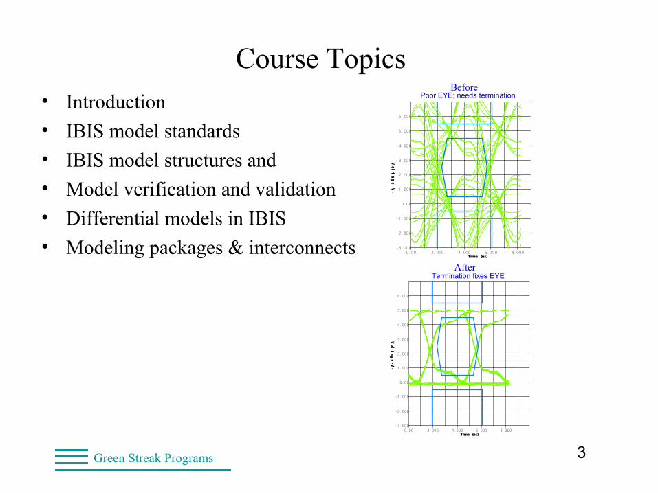
Course Topics• Introduction
• IBIS model standards
• IBIS model structures and
• Model verification and validation
• Differential models in IBIS
• Modeling packages & interconnects
OSCILLOSCOPEDesign file: CLOCK.TLN Designer: Lynne D. Green
HyperLynx V7.7Comment: Poor EYE - needs termination
Date: Tuesday Aug. 7, 2007 Time: 22:11:01
- 3. 000
- 2. 000
- 1 . 000
0. 00
1 . 000
2. 000
3. 000
4. 000
5. 000
6. 000
0 . 00 2. 000 4. 000 6 . 000 8. 000Time (ns)
Vol
tag
e - V-
BeforePoor EYE; needs termination
OSCILLOSCOPEDesign file: CLOCKFIX.TLN Designer: Lynne D. Green
HyperLynx V7.7Comment: Termination fixes EYE problem
Date: Tuesday Aug. 7, 2007 Time: 22:18:19
- 3. 000
- 2. 000
- 1 . 000
0. 00
1 . 000
2. 000
3. 000
4. 000
5. 000
6. 000
0. 00 2. 000 4. 000 6 . 000 8. 000Time (ns)
Vol
tag
e - V-
AfterTermination fixes EYE
4Green Streak Programs
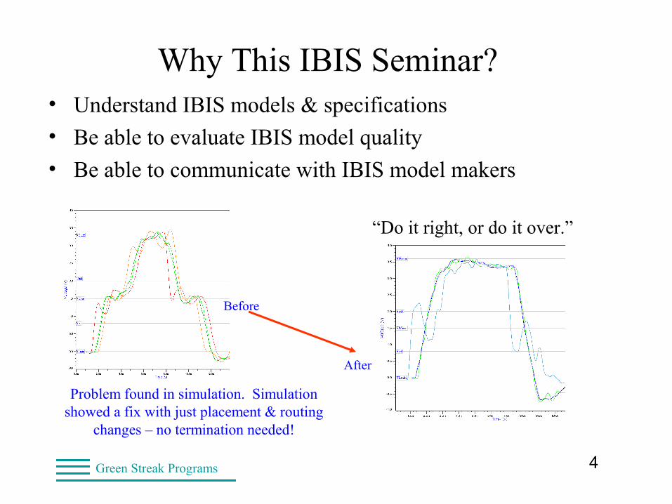
Why This IBIS Seminar?• Understand IBIS models & specifications
• Be able to evaluate IBIS model quality
• Be able to communicate with IBIS model makers
“Do it right, or do it over.”
Problem found in simulation. Simulation showed a fix with just placement & routing
changes – no termination needed!
Before
After
5Green Streak Programs
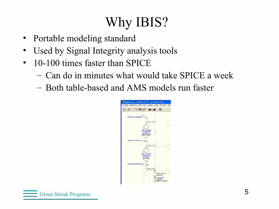
Why IBIS?• Portable modeling standard• Used by Signal Integrity analysis tools• 10-100 times faster than SPICE
– Can do in minutes what would take SPICE a week– Both table-based and AMS models run faster
6Green Streak Programs
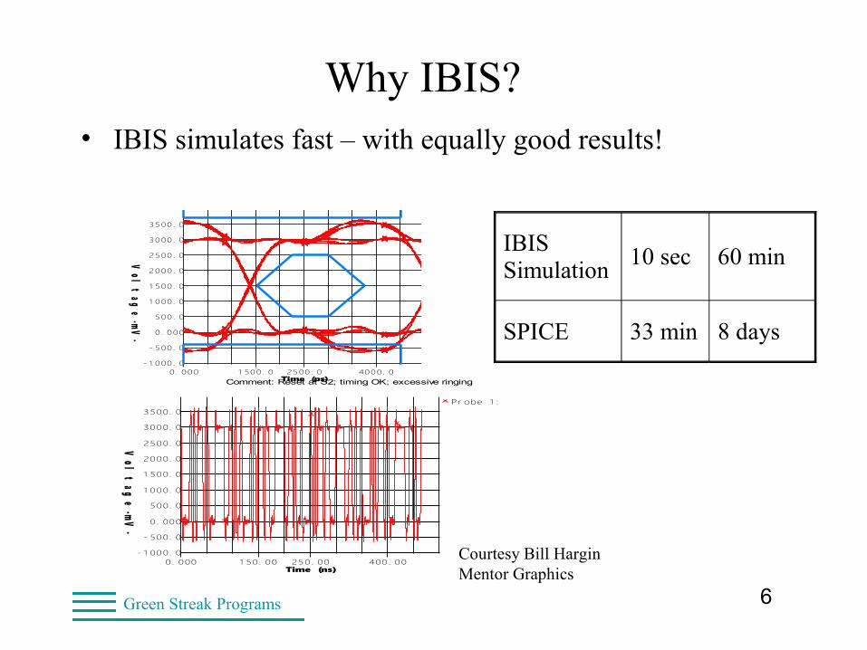
Why IBIS?• IBIS simulates fast – with equally good results!
IBIS Simulation
10 sec 60 min
SPICE 33 min 8 days
OSCILLOSCOPEDesign file: DEMO.HYP Designer: Lynne D. Green
HyperLynx V7.5Comment: Reset at S2; timing OK; excessive ringing
Date: Wednesday Nov. 2, 2005 Time: 13:39:27Net name: reset
- 1 000 . 0
- 500 . 0
0 . 000
500. 0
1 000 . 0
1 500 . 0
2000. 0
2500. 0
3000. 0
3500. 0
0. 000 1 500. 0 2500. 0 4000. 0Time (ps)
Vol
tag
e -mV-
OSCILLOSCOPEDesign file: DEMO.HYP Designer: Lynne D. Green
HyperLynx V7.5Comment: Reset at S2; timing OK; excessive ringing
Date: Wednesday Nov. 2, 2005 Time: 13:40:35Net name: reset
Show Latest Waveform = YES
- 1 000. 0
- 500. 0
0. 000
500. 0
1 000. 0
1 500. 0
2000. 0
2500. 0
3000. 0
3500. 0
0. 000 1 50. 00 250. 00 400 . 00Time (ns)
Vol
tag
e -mV-
Pr obe 1 : S2. 2 ( a t pi n)
Courtesy Bill HarginMentor Graphics
7Green Streak Programs
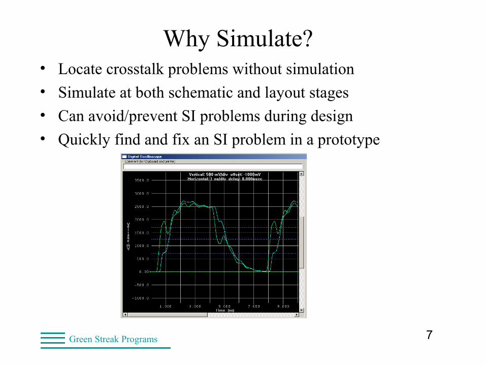
Why Simulate?• Locate crosstalk problems without simulation
• Simulate at both schematic and layout stages
• Can avoid/prevent SI problems during design
• Quickly find and fix an SI problem in a prototype
8Green Streak Programs
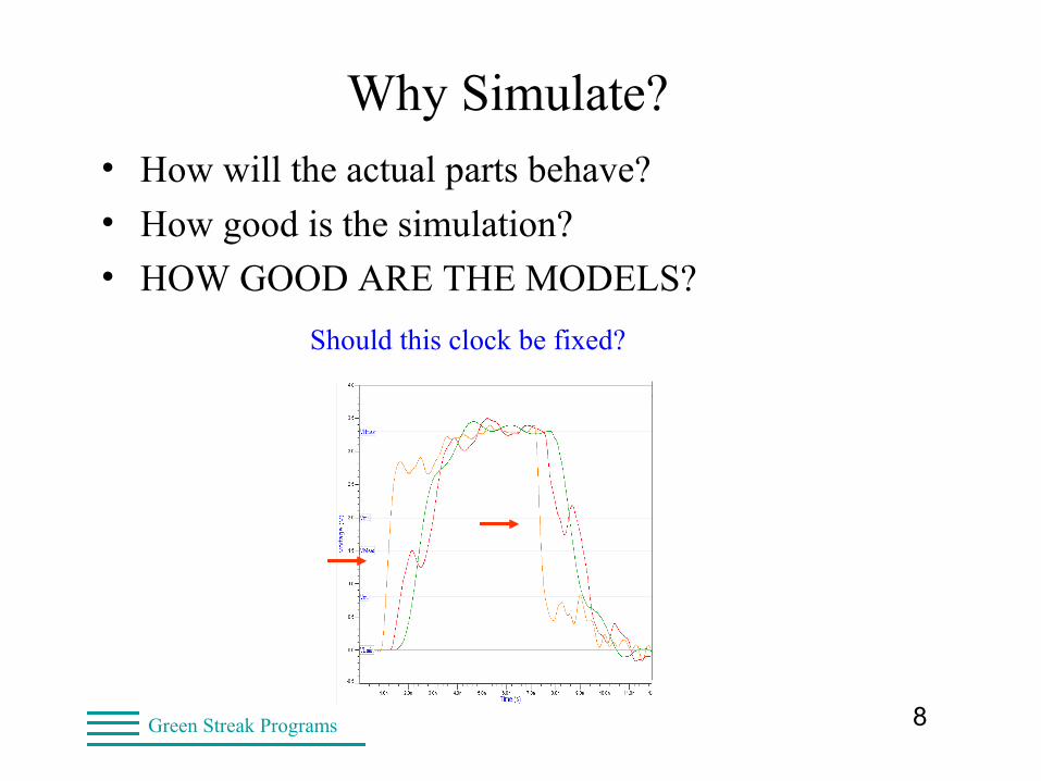
Why Simulate?• How will the actual parts behave?
• How good is the simulation?
• HOW GOOD ARE THE MODELS?
Should this clock be fixed?
9Green Streak Programs
IBIS Quality = SI Quality = Product Quality
• Without signal integrity checks in the design flow
– Early failures in the field
– Intermittent faults (fun to debug)
– Expensive replacement
– Reduced customer satisfaction
• With IBIS simulation
– Prototypes function and are easier to debug
– Functional units are more reliable
– Rockwell maintains high product reliability
10Green Streak Programs
IBIS Application Significance• High-speed designs rely on SI simulation
– Routing rules between components/cards/modules
– Check routing on the PCB layout
– First pass working functional prototypes
• The signal you don’t check
– Random RESET at Rockwell Automation
– Random RESET at Intel
– Crosstalk to nearby traces driven by fast edges
– Major field returns are expensive
11Green Streak Programs
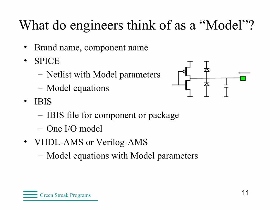
What do engineers think of as a “Model”?
• Brand name, component name
• SPICE
– Netlist with Model parameters
– Model equations
• IBIS
– IBIS file for component or package
– One I/O model
• VHDL-AMS or Verilog-AMS
– Model equations with Model parameters
12Green Streak Programs
• Level of abstraction
– Electrons, fields, bonds (physics/chemistry)
– Ideal circuit elements (SPICE)
– Black box circuits (IBIS)
– Black box systems (VHDL-AMS, Verilog-AMS)
• Model equations based on known behavior
– SPICE and IBIS are both “behavioral”
• More abstract often viewed as more “behavioral”
What is a “behavioral” model?
13Green Streak Programs
• Advantages of abstraction
– Faster simulation
– Allows view of overall system
– View at different levels of abstraction
• The cost of abstraction
– Harder to extend to new circuits/systems
– Further away from physical understanding
What is a “behavioral” model?
14Green Streak Programs
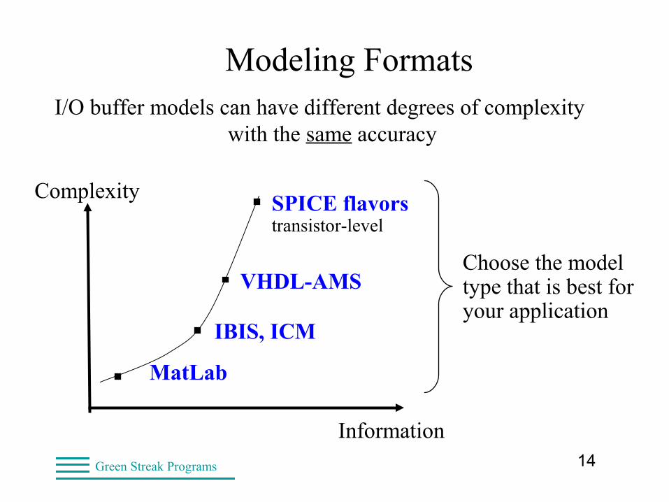
Modeling FormatsI/O buffer models can have different degrees of complexity
with the same accuracy
Complexity
Information
VHDL-AMS
IBIS, ICM
Choose the model type that is best for your application
MatLab
SPICE flavorstransistor-level
15Green Streak Programs
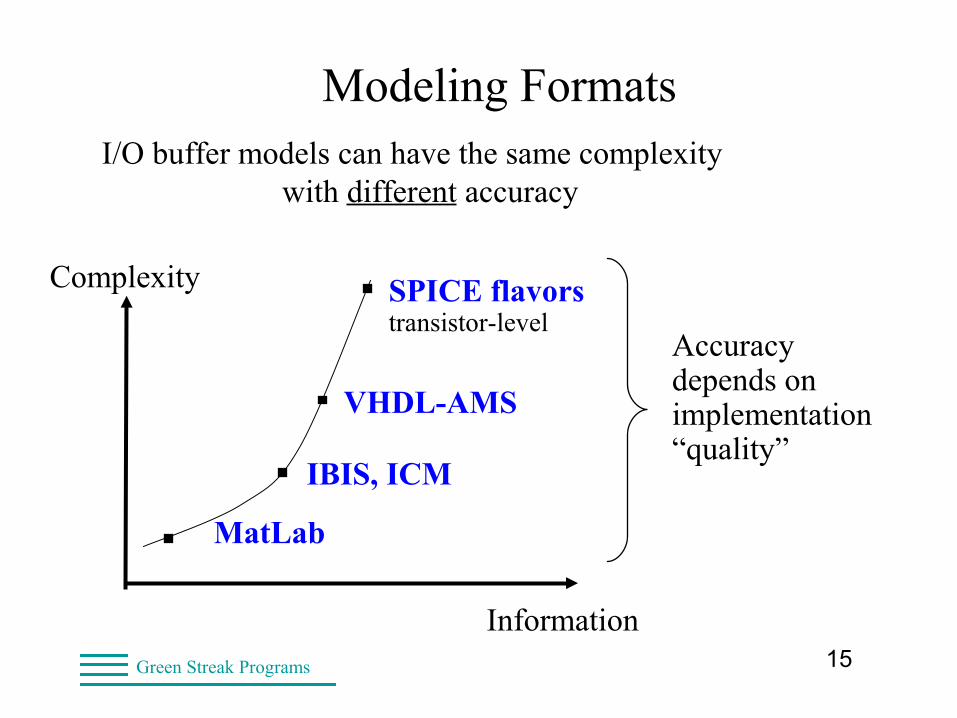
Modeling FormatsI/O buffer models can have the same complexity
with different accuracy
Complexity
Information
VHDL-AMS
IBIS, ICM
Accuracy depends on implementation “quality”
MatLab
SPICE flavorstransistor-level
16Green Streak Programs
Model Quality• Issues with SPICE models
– Parameter fitting to measured data
– Component equations hard-coded
– Different parameter meanings between “flavors”
• Issues with IBIS models
– Often made from SPICE
– Incorrect data or typos
– Not checked before release
“Garbage IN, Garbage OUT”
17Green Streak Programs
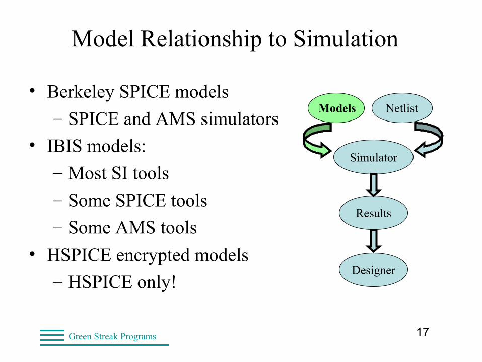
Model Relationship to Simulation
• Berkeley SPICE models
– SPICE and AMS simulators
• IBIS models:
– Most SI tools
– Some SPICE tools
– Some AMS tools
• HSPICE encrypted models
– HSPICE only!
Simulator
Models Netlist
Results
Designer
18Green Streak Programs
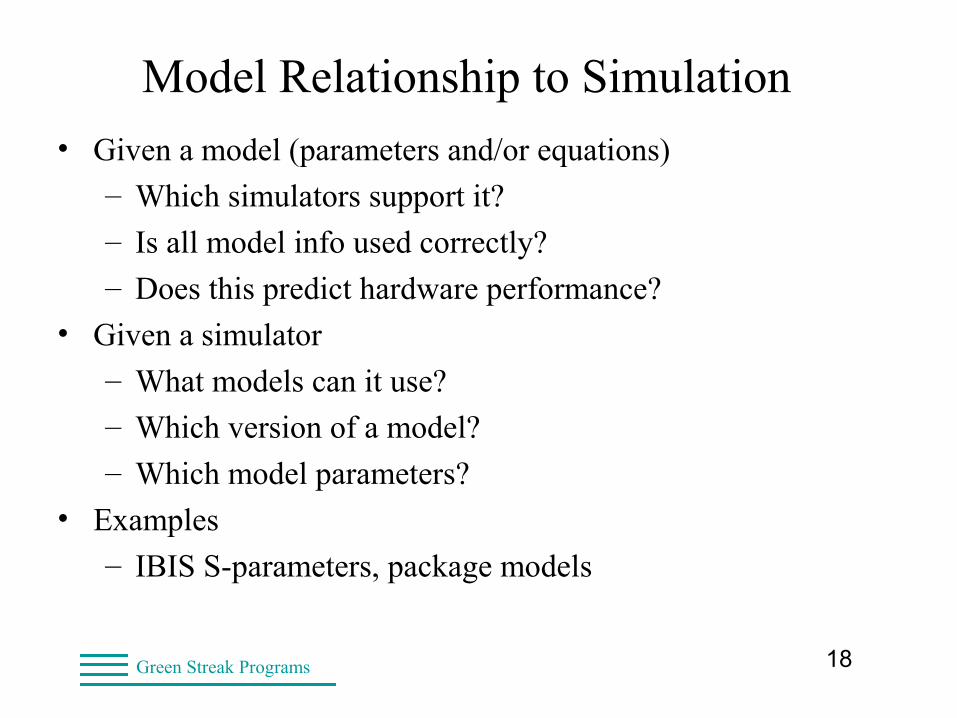
• Given a model (parameters and/or equations)
– Which simulators support it?
– Is all model info used correctly?
– Does this predict hardware performance?
• Given a simulator
– What models can it use?
– Which version of a model?
– Which model parameters?
• Examples
– IBIS S-parameters, package models
Model Relationship to Simulation
19Green Streak Programs
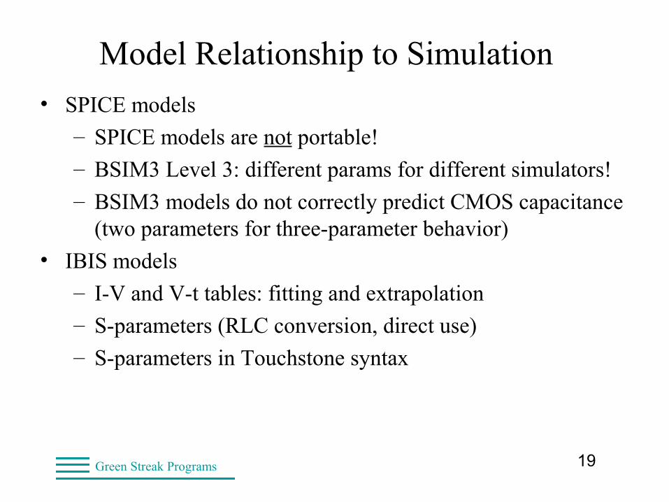
• SPICE models
– SPICE models are not portable!
– BSIM3 Level 3: different params for different simulators!
– BSIM3 models do not correctly predict CMOS capacitance(two parameters for three-parameter behavior)
• IBIS models
– I-V and V-t tables: fitting and extrapolation
– S-parameters (RLC conversion, direct use)
– S-parameters in Touchstone syntax
Model Relationship to Simulation
20Green Streak Programs
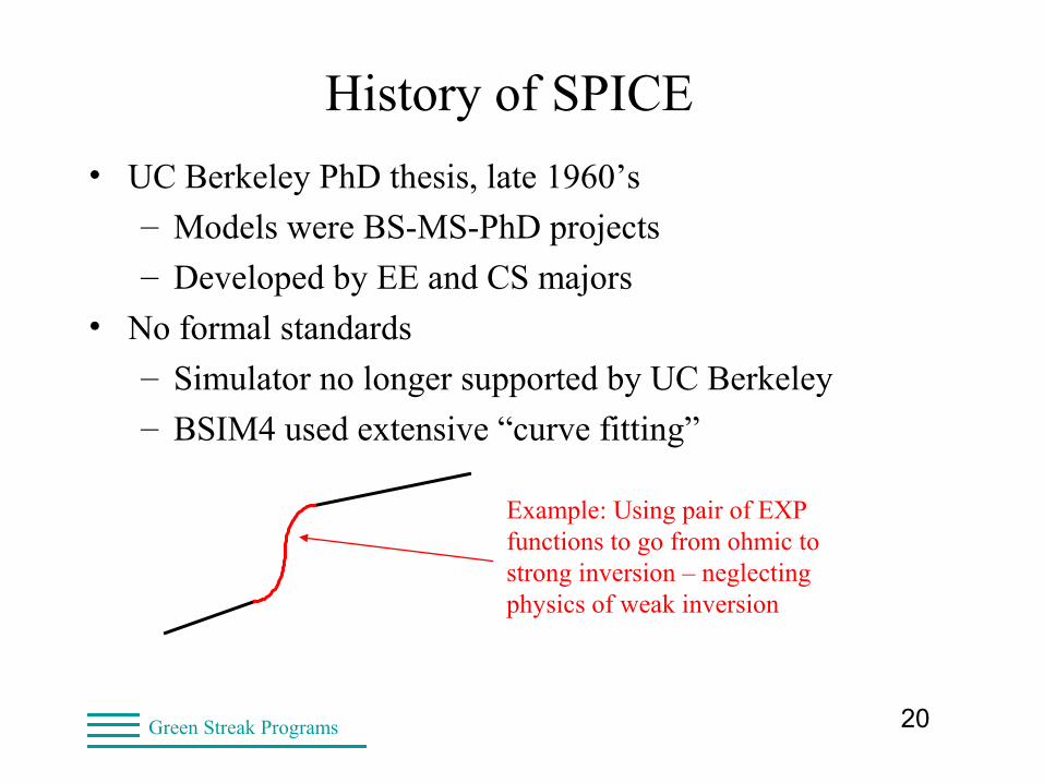
History of SPICE
• UC Berkeley PhD thesis, late 1960’s
– Models were BS-MS-PhD projects
– Developed by EE and CS majors
• No formal standards
– Simulator no longer supported by UC Berkeley
– BSIM4 used extensive “curve fitting”
Example: Using pair of EXP functions to go from ohmic to strong inversion – neglecting physics of weak inversion

21Green Streak Programs
SPICE’s Future• SPICE has limitations
– Model equations are usually hard coded
• (MOSFET level=xx)
– Users only supply coefficients to existing equations
– Deep sub-micron devices need new equations
• Custom SPICE versions
– Same problems, faster response
– Harder to maintain (smaller staff)
Green Streak Programs
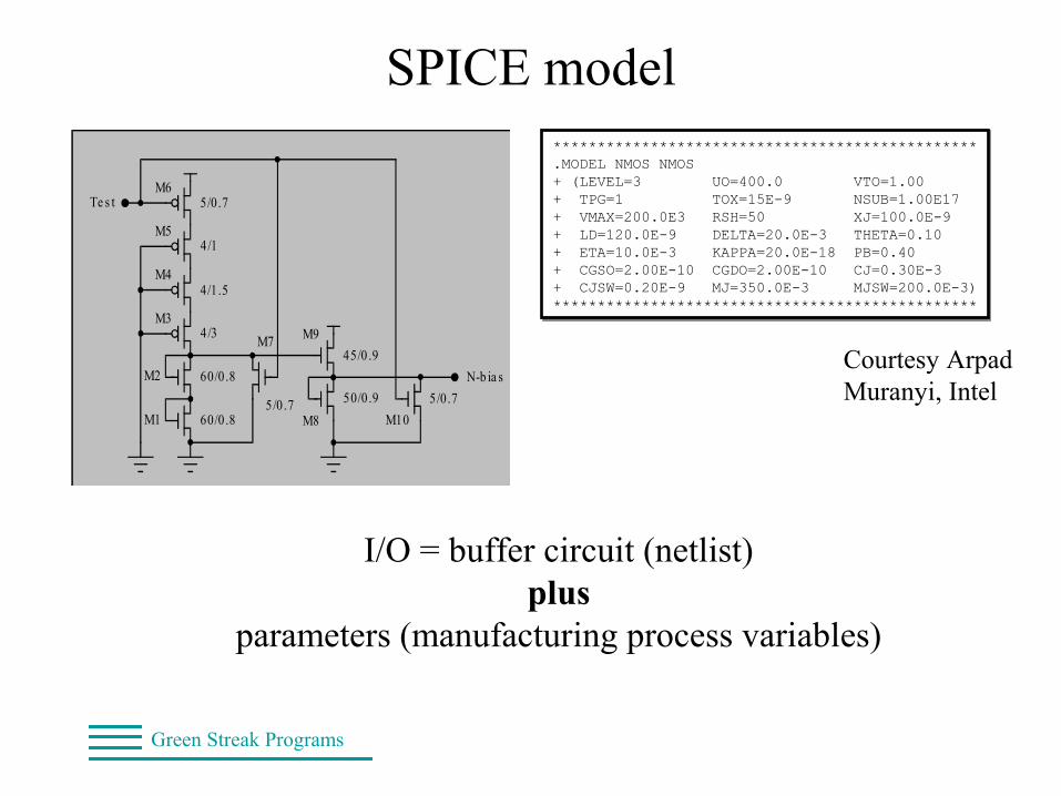
SPICE model
I/O = buffer circuit (netlist)plus
parameters (manufacturing process variables)
************************************************.MODEL NMOS NMOS+ (LEVEL=3 UO=400.0 VTO=1.00+ TPG=1 TOX=15E-9 NSUB=1.00E17+ VMAX=200.0E3 RSH=50 XJ=100.0E-9+ LD=120.0E-9 DELTA=20.0E-3 THETA=0.10+ ETA=10.0E-3 KAPPA=20.0E-18 PB=0.40+ CGSO=2.00E-10 CGDO=2.00E-10 CJ=0.30E-3+ CJSW=0.20E-9 MJ=350.0E-3 MJSW=200.0E-3)************************************************
************************************************.MODEL NMOS NMOS+ (LEVEL=3 UO=400.0 VTO=1.00+ TPG=1 TOX=15E-9 NSUB=1.00E17+ VMAX=200.0E3 RSH=50 XJ=100.0E-9+ LD=120.0E-9 DELTA=20.0E-3 THETA=0.10+ ETA=10.0E-3 KAPPA=20.0E-18 PB=0.40+ CGSO=2.00E-10 CGDO=2.00E-10 CJ=0.30E-3+ CJSW=0.20E-9 MJ=350.0E-3 MJSW=200.0E-3)************************************************
Te s t
N-b ia s
5/0.7
4/1
4/1.5
4/3
60/0 .8
60/0 .85/0.7
45/0 .9
50/0 .9 5/0.7
M1
M2
M3
M4
M5
M6
M7
M8
M9
M10
Te s t
N-b ia s
5/0.7
4/1
4/1.5
4/3
60/0 .8
60/0 .85/0.7
45/0 .9
50/0 .9 5/0.7
M1
M2
M3
M4
M5
M6
M7
M8
M9
M10
Courtesy Arpad Muranyi, Intel
23Green Streak Programs
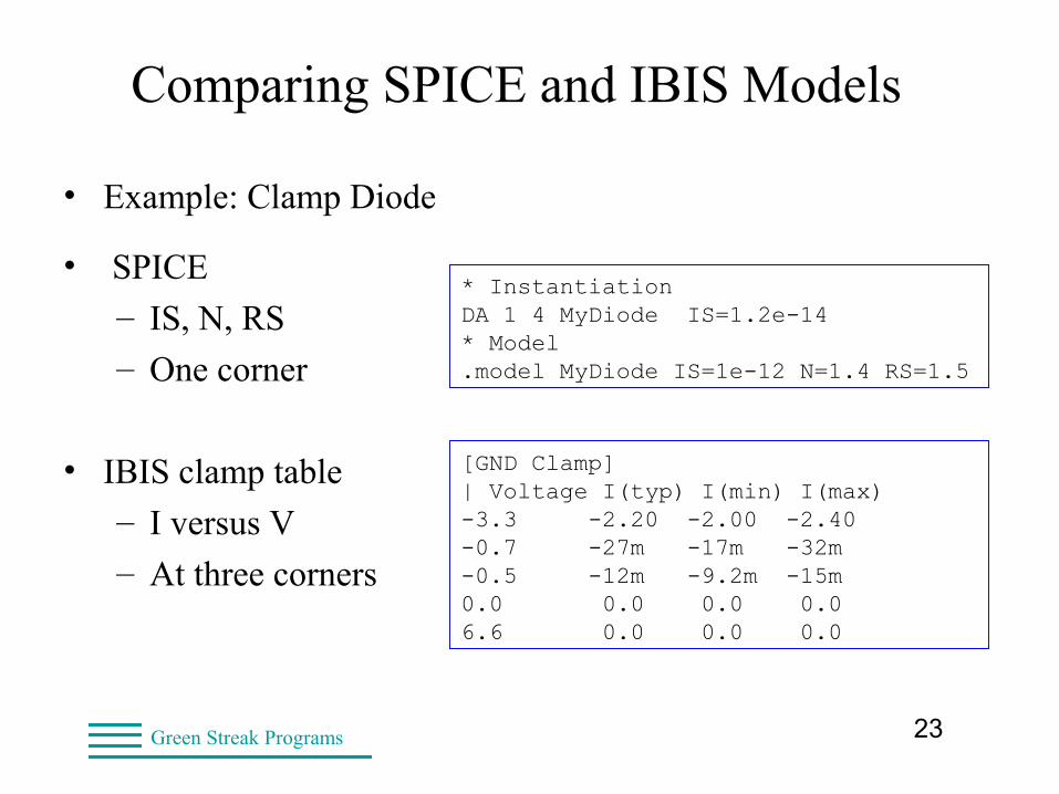
Comparing SPICE and IBIS Models
• Example: Clamp Diode
• SPICE
– IS, N, RS
– One corner
• IBIS clamp table
– I versus V
– At three corners
[GND Clamp]| Voltage I(typ) I(min) I(max)-3.3 -2.20 -2.00 -2.40-0.7 -27m -17m -32m-0.5 -12m -9.2m -15m0.0 0.0 0.0 0.06.6 0.0 0.0 0.0
* InstantiationDA 1 4 MyDiode IS=1.2e-14* Model.model MyDiode IS=1e-12 N=1.4 RS=1.5
24Green Streak Programs
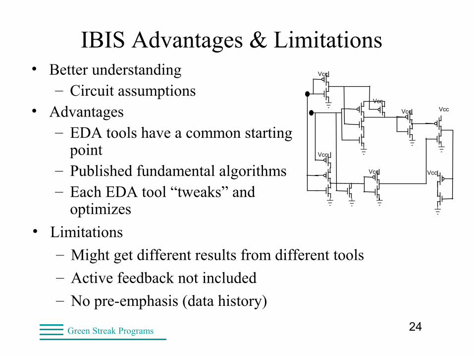
IBIS Advantages & Limitations• Better understanding
– Circuit assumptions• Advantages
– EDA tools have a common starting point
– Published fundamental algorithms– Each EDA tool “tweaks” and
optimizes
Vcc
Vcc
Vcc
Vcc
Vcc
Vcc
Vcc
• Limitations
– Might get different results from different tools
– Active feedback not included
– No pre-emphasis (data history)
25Green Streak Programs
• Portable I/O models for Signal Integrity analysis
• Analog behavior of digital I/O buffers
• Plain ASCII text formatted data
• Supplement to data sheet
• Used by SI simulators (ex: HyperLynx, ICX)
A Closer Look at IBIS
I / OB ufferI nformationS pecification
26Green Streak Programs
IBIS History• Founding companies
– Intel, HyperLynx, Mentor Graphics, Cadence, Quad
• Goals were:
– PCI simulation
– Protect intellectual property (modeldatasheet)
– Simulate circuits with/without probe loading
– See signal inside package (at die)
– See signal outside (pads and vias)
– See signal at unprobable points (blind/buried vias)
27Green Streak Programs
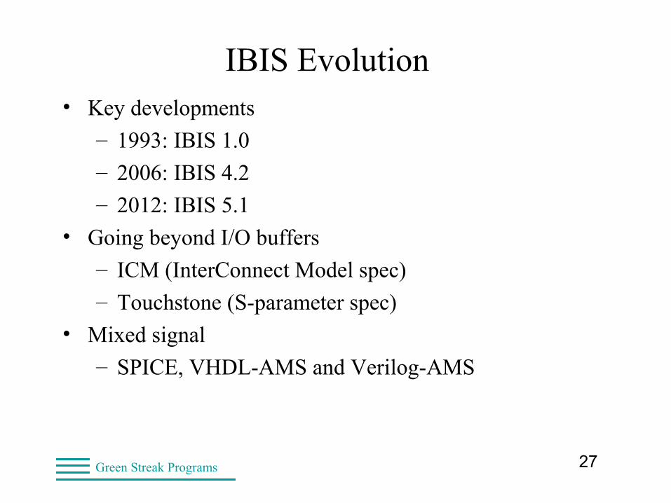
IBIS Evolution• Key developments
– 1993: IBIS 1.0
– 2006: IBIS 4.2
– 2012: IBIS 5.1
• Going beyond I/O buffers
– ICM (InterConnect Model spec)
– Touchstone (S-parameter spec)
• Mixed signal
– SPICE, VHDL-AMS and Verilog-AMS
28Green Streak Programs
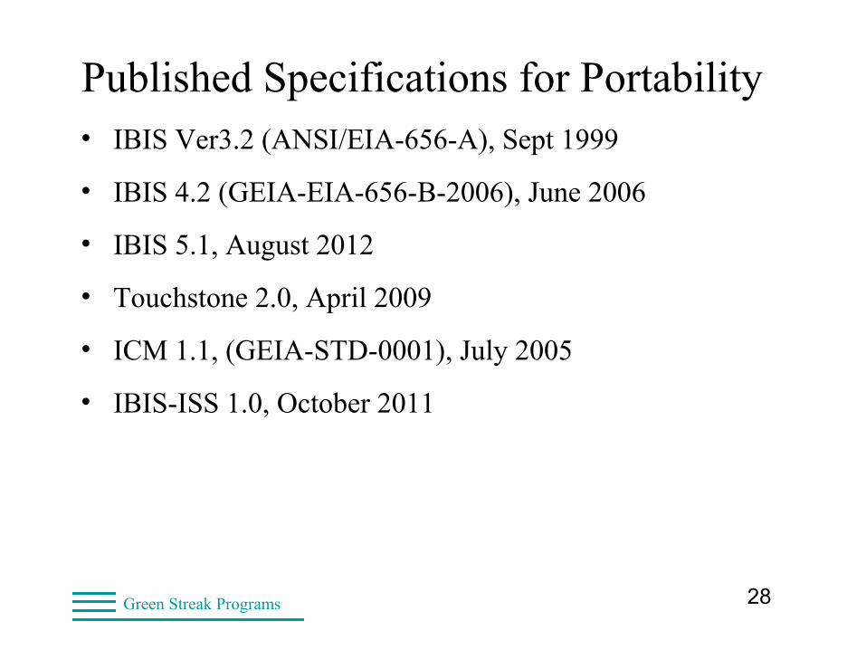
Published Specifications for Portability• IBIS Ver3.2 (ANSI/EIA-656-A), Sept 1999
• IBIS 4.2 (GEIA-EIA-656-B-2006), June 2006
• IBIS 5.1, August 2012
• Touchstone 2.0, April 2009
• ICM 1.1, (GEIA-STD-0001), July 2005
• IBIS-ISS 1.0, October 2011
29Green Streak Programs
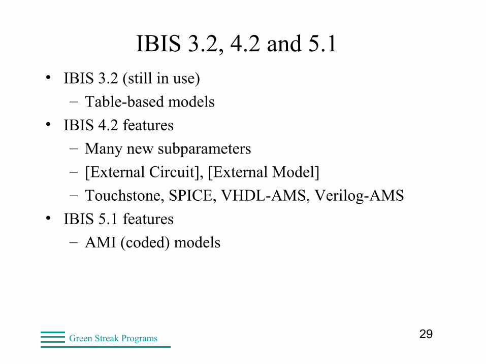
IBIS 3.2, 4.2 and 5.1• IBIS 3.2 (still in use)
– Table-based models
• IBIS 4.2 features
– Many new subparameters
– [External Circuit], [External Model]
– Touchstone, SPICE, VHDL-AMS, Verilog-AMS
• IBIS 5.1 features
– AMI (coded) models
30Green Streak Programs
IBIS 3.2: example.ibs• [IBIS Ver] 3.2
• Header
– Required data
– Optional data
• Component data
– Required data
– Optional data
• Model data
– Required data
– Optional data

31Green Streak Programs
IBIS 4.2 Example• [IBIS Ver] 4.2
• Header
– Required data
– Optional data
• Component data
– Required data
– Optional data
• Model data
– Required data
– Optional data
32Green Streak Programs
IBIS 5.1 Example• [IBIS Ver] 5.1
• Header
– Required data
– Optional data
• Component data
– Required data
– Optional data
• Model data
– Required data
– Optional data
33Green Streak Programs
Coming Soon• Functionality
– AMI enhancements (parameters)
– [External Circuit] and [Model Call] features
– Touchstone and SPICE for package models
• Documents
– Updated Quality Checklist
– Enhanced IBIS Cookbook
34Green Streak Programs
IBIS Applications• Today, IBIS is used extensively for simulation
– Much faster than SPICE
– Signal quality (ringing, overshoot, undershoot)
– Timing (min/max delays)
• Pre-layout analysis
– Over corner cases
– Component choices, driver selection
– Maximum distance between components
– Routing topology and termination impacts
• Stack-up definition to guarantee impedance
• Minimum trace spacing to reduce crosstalk
• Differential routing
35Green Streak Programs
IBIS Applications• Post-layout verification
– Verify signal quality against requirements
– Verify timing against requirements
– Based on actual placement and routing
– Over corner cases
• At 10 Gbit/sec
– Without simulation, 10 board turns (or more)
– With IBIS, first prototype often functional
36Green Streak Programs
Common Way to Create IBIS Models• Get parameters from datasheet
– Vcc, Vinh, Vinl
– Chip Tr/Tf
– Test load
• Put parameters into prototype IBIS file• Run s2ibis3 (http://iometh.com/Product/s2ibis3/index.html)
– Extracts table data for ONE model
• Multiple models or other simulator
– Custom script to extract table data
• Manual editing for additional features
37Green Streak Programs
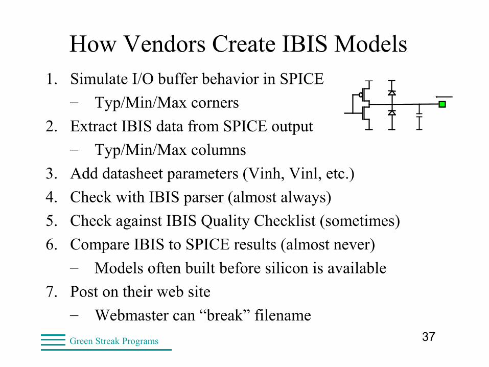
How Vendors Create IBIS Models1. Simulate I/O buffer behavior in SPICE
– Typ/Min/Max corners
2. Extract IBIS data from SPICE output
– Typ/Min/Max columns
3. Add datasheet parameters (Vinh, Vinl, etc.)
4. Check with IBIS parser (almost always)
5. Check against IBIS Quality Checklist (sometimes)
6. Compare IBIS to SPICE results (almost never)
– Models often built before silicon is available
7. Post on their web site
– Webmaster can “break” filename
38Green Streak Programs
IBIS Quality: Really Good Vendors• Make IBIS Quality checks
• Make their own (additional) checks
• Simulate in a commercial IBIS tool
• Document details in the IBIS file
– Which “SPICE” and transistor model library
– Which quality checks were made
– Any issues user might encounter
• Post IBIS file on their web site
– Some post notice & release under NDA
39Green Streak Programs
IBIS Quality: The Truth• Not all vendors make quality IBIS models
– Experience not transferred
– Don’t run checks with latest IBIS parser
– Don’t use the IBIS Quality Checklist
• Incoming inspection of models is always needed
– Does model pass parser
– Do data tables look normal
• There are some very good model makers out there
– But they might retire or move on
40Green Streak Programs
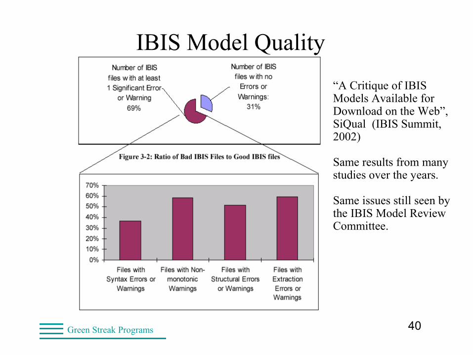
“A Critique of IBIS Models Available for Download on the Web”, SiQual (IBIS Summit, 2002)
Same results from many studies over the years.
Same issues still seen by the IBIS Model Review Committee.
IBIS Model Quality
41Green Streak Programs
IBIS Library Methodology
• Models require validation
– Vendor might not validate
– Only needs to be done once per model
– Less than 15 minutes for a simple model
• Who does validation
– Model Librarian (incoming inspection)
– Hardware Engineers (prototypes)
– Signal Integrity Engineers (model debugging)
42Green Streak Programs
Typical Components With IBIS Models
• Microprocessors, Microcontrollers
• Memory (Asynchronous, Synchronous)
• Logic Devices (Gates, Buffers, Transceivers)
• Programmable Logic Devices
• ASICs
• Connectors, backplanes, daughter cards
– Multiboard Applications
• Packaged passives
– Resistors, Capacitors, Inductors
– Termination cards (SPICE, Touchstone)
43Green Streak Programs
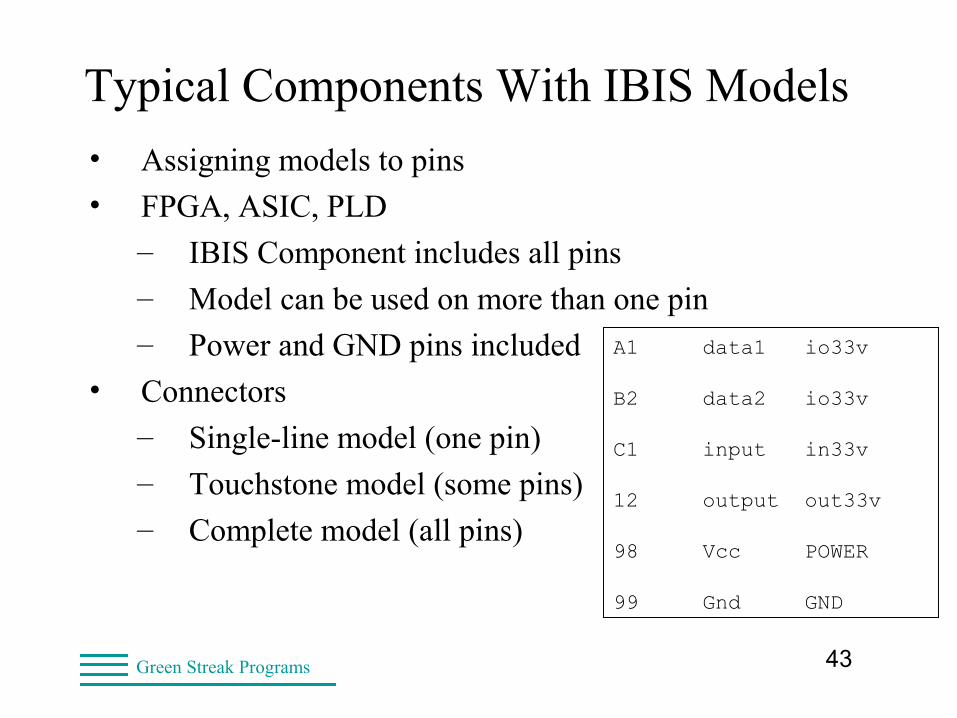
Typical Components With IBIS Models
• Assigning models to pins
• FPGA, ASIC, PLD
– IBIS Component includes all pins
– Model can be used on more than one pin
– Power and GND pins included
• Connectors
– Single-line model (one pin)
– Touchstone model (some pins)
– Complete model (all pins)
A1 data1 io33v B2 data2 io33v C1 input in33v 12 output out33v 98 Vcc POWER 99 Gnd GND
44Green Streak Programs
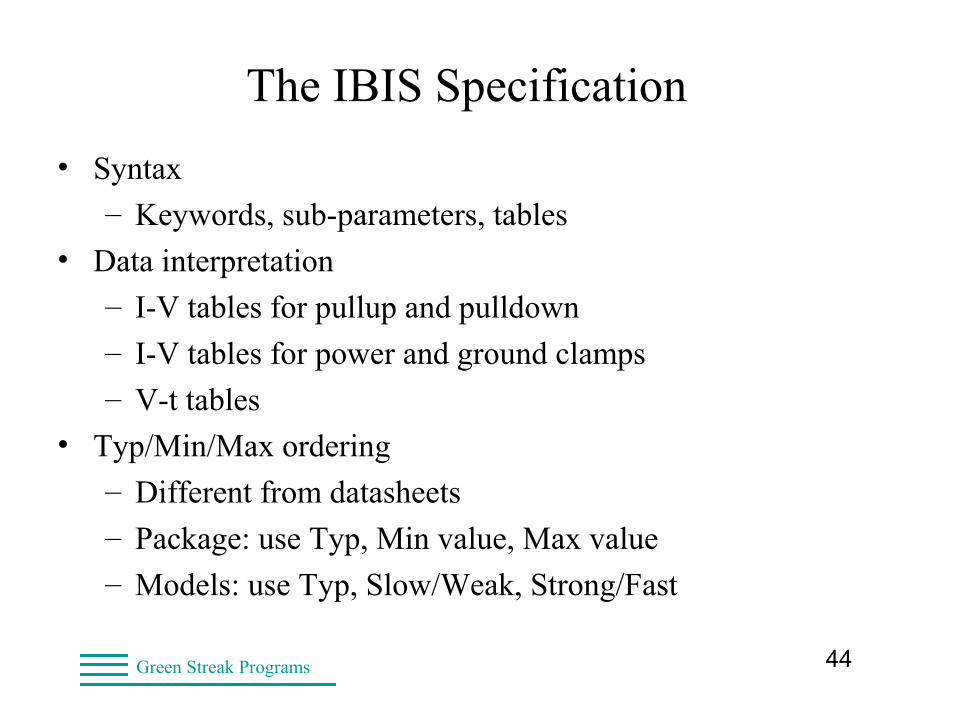
The IBIS Specification
• Syntax
– Keywords, sub-parameters, tables
• Data interpretation
– I-V tables for pullup and pulldown
– I-V tables for power and ground clamps
– V-t tables
• Typ/Min/Max ordering
– Different from datasheets
– Package: use Typ, Min value, Max value
– Models: use Typ, Slow/Weak, Strong/Fast
45Green Streak Programs
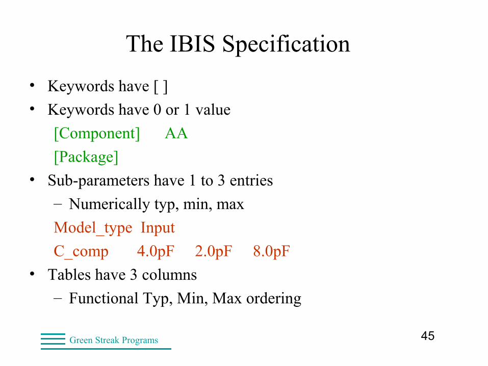
The IBIS Specification
• Keywords have [ ]
• Keywords have 0 or 1 value
[Component] AA
[Package]
• Sub-parameters have 1 to 3 entries
– Numerically typ, min, max
Model_type Input
C_comp 4.0pF 2.0pF 8.0pF
• Tables have 3 columns
– Functional Typ, Min, Max ordering
46Green Streak Programs
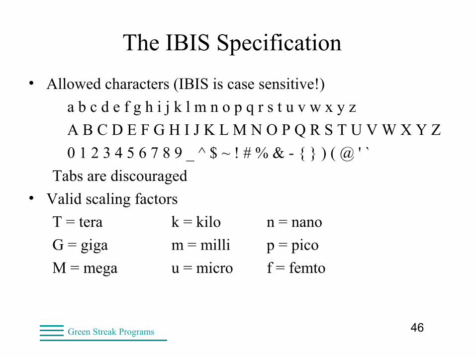
The IBIS Specification
• Allowed characters (IBIS is case sensitive!)
a b c d e f g h i j k l m n o p q r s t u v w x y z
A B C D E F G H I J K L M N O P Q R S T U V W X Y Z
0 1 2 3 4 5 6 7 8 9 _ ^ $ ~ ! # % & - { } ) ( @ ' `
Tabs are discouraged
• Valid scaling factors
T = tera k = kilo n = nano
G = giga m = milli p = pico
M = mega u = micro f = femto
47Green Streak Programs
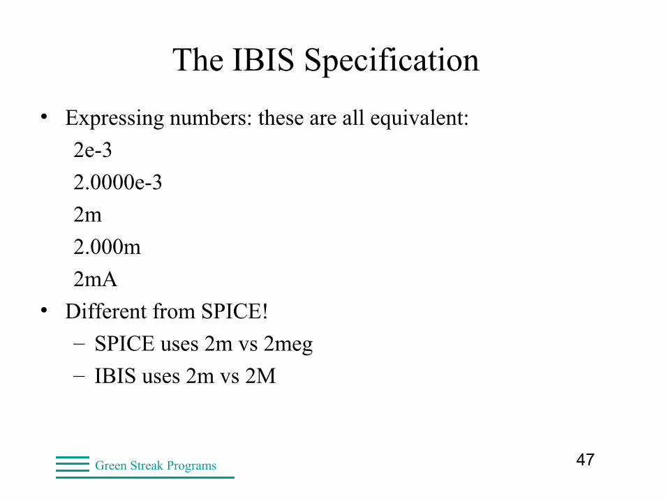
The IBIS Specification
• Expressing numbers: these are all equivalent:
2e-3
2.0000e-3
2m
2.000m
2mA
• Different from SPICE!
– SPICE uses 2m vs 2meg
– IBIS uses 2m vs 2M
48Green Streak Programs
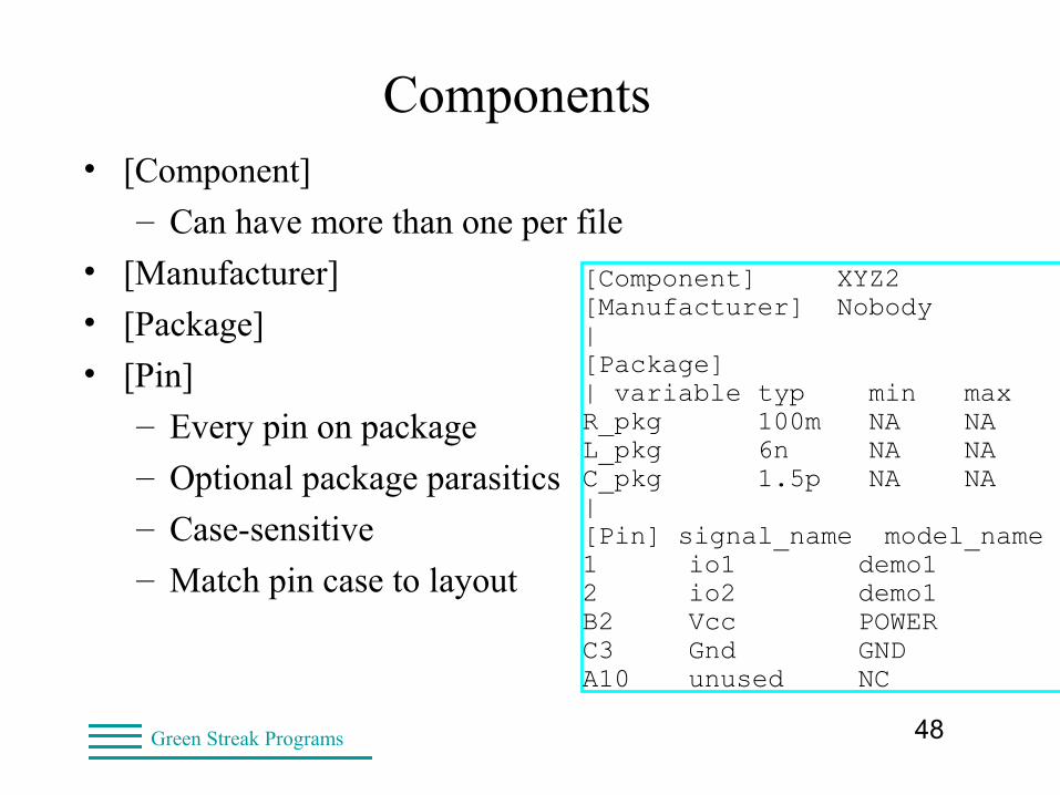
Components• [Component]
– Can have more than one per file
• [Manufacturer]
• [Package]
• [Pin]
– Every pin on package
– Optional package parasitics
– Case-sensitive
– Match pin case to layout
[Component] XYZ2[Manufacturer] Nobody|[Package]| variable typ min maxR_pkg 100m NA NAL_pkg 6n NA NAC_pkg 1.5p NA NA|[Pin] signal_name model_name1 io1 demo12 io2 demo1B2 Vcc POWERC3 Gnd GNDA10 unused NC

49Green Streak Programs
Components• [Package]
– IBIS package defined as “lumped”
– Some tools generate “distributed” equivalent
– Different results from different tools
• High speed - use full package model (pkg, icm, ts, iss)
– [Package] values still required
[Package]| variable typ min maxR_pkg 100m NA NAL_pkg 6n NA NAC_pkg 1.5p NA NA|
50Green Streak Programs
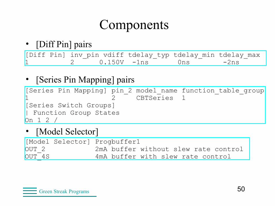
Components• [Diff Pin] pairs
• [Series Pin Mapping] pairs
• [Model Selector]
[Diff Pin] inv_pin vdiff tdelay_typ tdelay_min tdelay_max1 2 0.150V -1ns 0ns -2ns
[Series Pin Mapping] pin_2 model_name function_table_group1 2 CBTSeries 1 [Series Switch Groups]| Function Group StatesOn 1 2 /
[Model Selector] Progbuffer1OUT_2 2mA buffer without slew rate controlOUT_4S 4mA buffer with slew rate control
51Green Streak Programs
The IBIS Specification
• The minimum IBIS file
– Header
– Component (one pin)
– I/O buffer
• Input: no tables
• I/O: pullup & pulldown
– [End]
• The minimum model lacks critical information
– But satisfies the syntax requirements
52Green Streak Programs
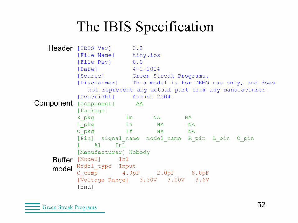
The IBIS Specification[IBIS Ver] 3.2[File Name] tiny.ibs[File Rev] 0.0[Date] 4-1-2004[Source] Green Streak Programs.[Disclaimer] This model is for DEMO use only, and does
not represent any actual part from any manufacturer. [Copyright] August 2004.[Component] AA [Package]R_pkg 1m NA NAL_pkg 1n NA NAC_pkg 1f NA NA[Pin] signal_name model_name R_pin L_pin C_pin1 A1 In1 [Manufacturer] Nobody[Model] In1Model_type InputC_comp 4.0pF 2.0pF 8.0pF[Voltage Range] 3.30V 3.00V 3.6V[End]
Header
Component
Buffer model

53Green Streak Programs
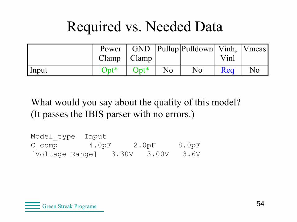
Required vs. Needed Data
Power Clamp
GNDClamp
Pullup Pulldown Vinh,Vinl
Vmeas
Input Opt* Opt* No No Req No Output Opt Opt Req Req No Opt! I/O Opt* Opt* Req Req Req Opt! 3–State Opt* Opt* Req Req Opt! Opt! Open_Sink Opt* Opt* No Req No Opt! I/O_Open_ Sink Opt* Opt* No Req Req Opt! Open_ Source Opt* Opt* Req No No Opt! IO_Open_ Source Opt* Opt* Req No Req Opt!
! Required for software timing checks!
*Needed for simulation of reflections!
54Green Streak Programs
Required vs. Needed Data Power Clamp
GNDClamp
Pullup Pulldown Vinh,Vinl
Vmeas
Input Opt* Opt* No No Req No
What would you say about the quality of this model?(It passes the IBIS parser with no errors.)
Model_type InputC_comp 4.0pF 2.0pF 8.0pF[Voltage Range] 3.30V 3.00V 3.6V
55Green Streak Programs
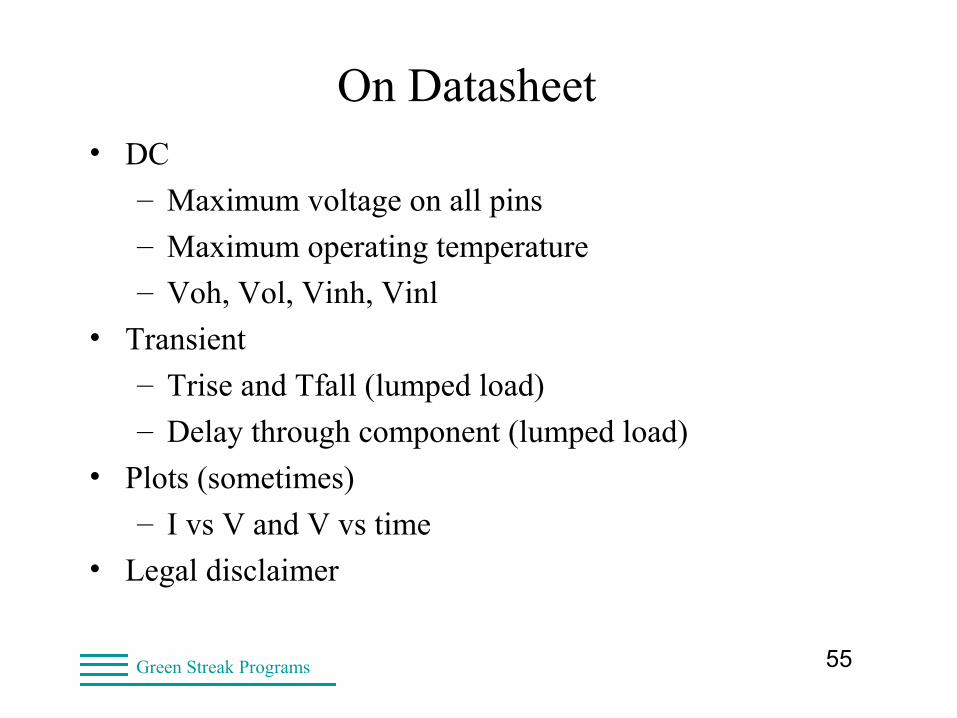
On Datasheet• DC
– Maximum voltage on all pins
– Maximum operating temperature
– Voh, Vol, Vinh, Vinl
• Transient
– Trise and Tfall (lumped load)
– Delay through component (lumped load)
• Plots (sometimes)
– I vs V and V vs time
• Legal disclaimer
56Green Streak Programs
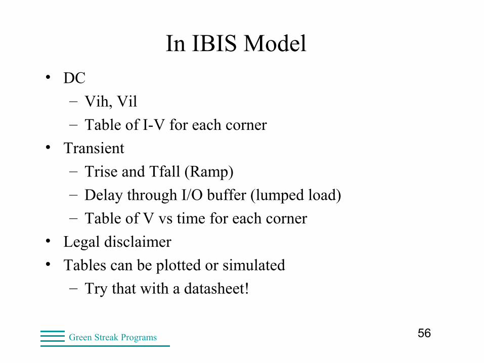
In IBIS Model• DC
– Vih, Vil
– Table of I-V for each corner
• Transient
– Trise and Tfall (Ramp)
– Delay through I/O buffer (lumped load)
– Table of V vs time for each corner
• Legal disclaimer
• Tables can be plotted or simulated
– Try that with a datasheet!
57Green Streak Programs
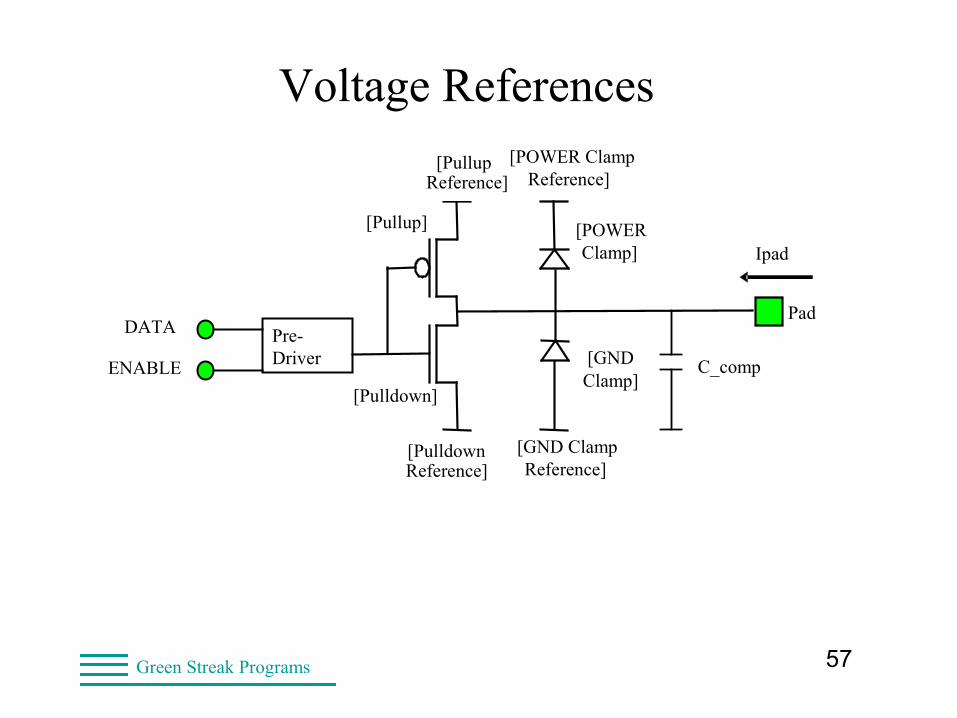
Voltage References
[POWER Clamp]
[GND
Clamp]
Pad
Ipad
[Pullup]
[Pulldown]
[Pulldown Reference]
[POWER Clamp Reference]
[GND Clamp
Reference]
[Pullup Reference]
C_comp
Pre-Driver
DATA
ENABLE
58Green Streak Programs
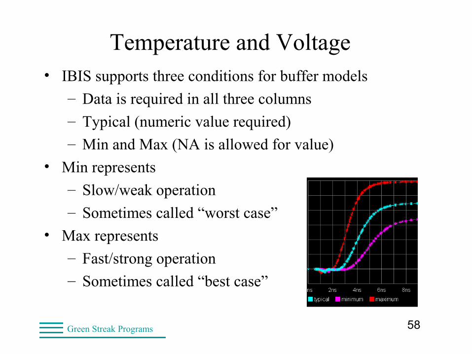
Temperature and Voltage• IBIS supports three conditions for buffer models
– Data is required in all three columns
– Typical (numeric value required)
– Min and Max (NA is allowed for value)
• Min represents
– Slow/weak operation
– Sometimes called “worst case”
• Max represents
– Fast/strong operation
– Sometimes called “best case”
59Green Streak Programs
Temperature and Voltage
• For CMOS
– Minimum conditions are:“slow” process, high temperature, low supply voltage
– Maximum conditions are:
• “fast” process, low temperature, high supply voltage
• For bipolar
– Minimum conditions are: “slow” process, low temperature, low supply voltage
– Maximum conditions are:“fast” process, high temperature, high supply voltage
60Green Streak Programs
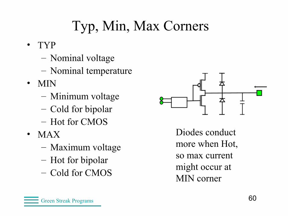
Typ, Min, Max Corners• TYP
– Nominal voltage– Nominal temperature
• MIN– Minimum voltage– Cold for bipolar– Hot for CMOS
• MAX– Maximum voltage– Hot for bipolar– Cold for CMOS
Diodes conduct more when Hot, so max current might occur at MIN corner
61Green Streak Programs
Typ, Min, Max Corners• Typ = Nominal voltage, temperature, process • CMOS
– Min @ min voltage, max temperature, and slow process– Max @ max voltage, min temperature, and fast process
• Bipolar– Min @ min voltage, min temperature, and slow process– Max @ max voltage, max temperature, and fast process
Important note: Temperature is die temperature, usually warmer than ambient. This is important in setting up SPICE simulations.
62Green Streak Programs
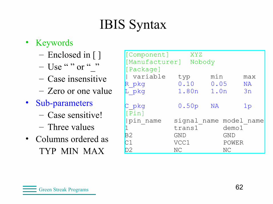
IBIS Syntax• Keywords
– Enclosed in [ ]– Use “ ” or “_”– Case insensitive– Zero or one value
• Sub-parameters– Case sensitive!– Three values
• Columns ordered asTYP MIN MAX
[Component] XYZ [Manufacturer] Nobody [Package] | variable typ min maxR_pkg 0.10 0.05 NAL_pkg 1.80n 1.0n 3n C_pkg 0.50p NA 1p[Pin]|pin_name signal_name model_name1 trans1 demo1 B2 GND GND C1 VCC1 POWERD2 NC NC
63Green Streak Programs
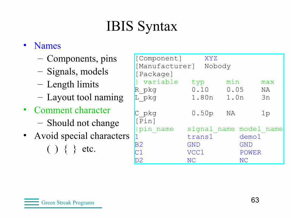
IBIS Syntax• Names
– Components, pins– Signals, models– Length limits– Layout tool naming
• Comment character– Should not change
• Avoid special characters( ) { } etc.
[Component] XYZ [Manufacturer] Nobody [Package] | variable typ min maxR_pkg 0.10 0.05 NAL_pkg 1.80n 1.0n 3n C_pkg 0.50p NA 1p[Pin]|pin_name signal_name model_name1 trans1 demo1 B2 GND GND C1 VCC1 POWERD2 NC NC

64Green Streak Programs
IBIS Data Interpretation• Output transitions under loading conditions
• Multiple V-t tables are allowed
– Not all tools use all tables
• Often get good accuracy with only one set
– R_fixture should be “near” actual Z0
http://www.ntu.edu.sg/home/ehntan/glsvlsi.zip
http://www.sigrity.com/papers/ectc96/DOectc96ibis.htm
65Green Streak Programs
IBIS Tables• IBIS uses tables to store data
– Equivalent to datasheet curves
– I-V table are DC characteristics
– V-t tables are dynamic/switching characteristics
• One column for each corner
– TYP is always FIRST
– Then MIN, then MAX
66Green Streak Programs
IBIS Tables• Table references
– GND for things that have 0 current when Vout=GND
• GND clamps, pulldowns
– Vcc for things that have 0 current when Vout=Vcc
• power clamps, pullups
– Time=0
• V-t tables (rising and falling waveforms)
• All tables must have the same reference
67Green Streak Programs
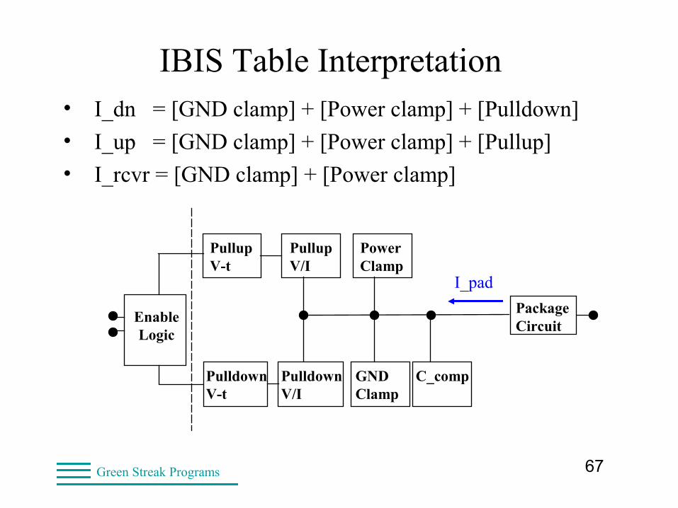
IBIS Table Interpretation• I_dn = [GND clamp] + [Power clamp] + [Pulldown]
• I_up = [GND clamp] + [Power clamp] + [Pullup]
• I_rcvr = [GND clamp] + [Power clamp]
PullupV-t
PullupV/I
PowerClamp
PackageCircuit
EnableLogic
GNDClamp
PulldownV/I
PulldownV-t
C_comp
I_pad
68Green Streak Programs
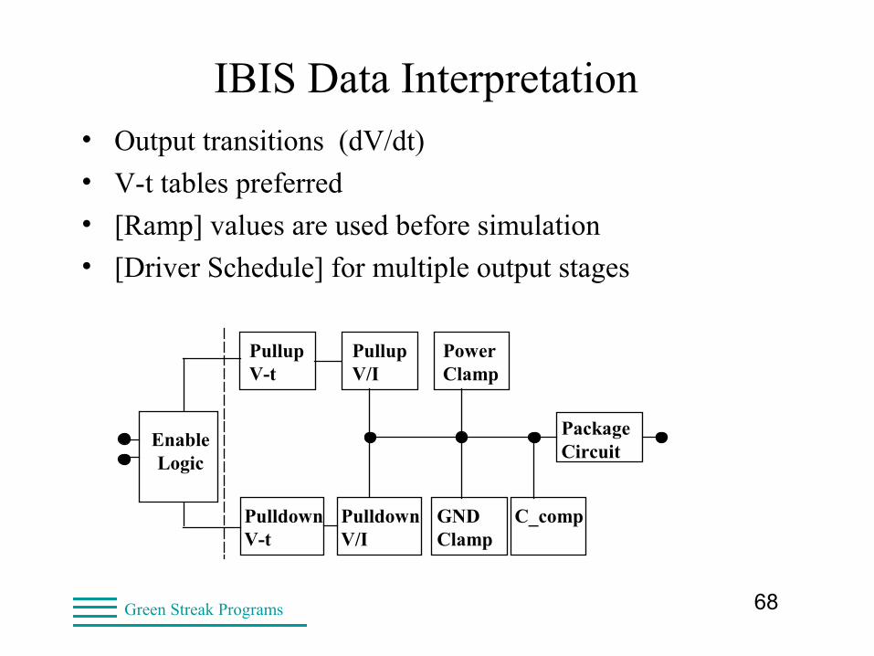
IBIS Data Interpretation• Output transitions (dV/dt)
• V-t tables preferred
• [Ramp] values are used before simulation
• [Driver Schedule] for multiple output stages
PullupV-t
PullupV/I
PowerClamp
PackageCircuit
EnableLogic
GNDClamp
PulldownV/I
PulldownV-t
C_comp
69Green Streak Programs
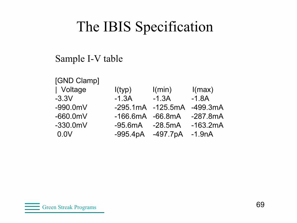
The IBIS Specification
Sample I-V table
[GND Clamp]| Voltage I(typ) I(min) I(max)-3.3V -1.3A -1.3A -1.8A-990.0mV -295.1mA -125.5mA -499.3mA-660.0mV -166.6mA -66.8mA -287.8mA-330.0mV -95.6mA -28.5mA -163.2mA 0.0V -995.4pA -497.7pA -1.9nA
70Green Streak Programs
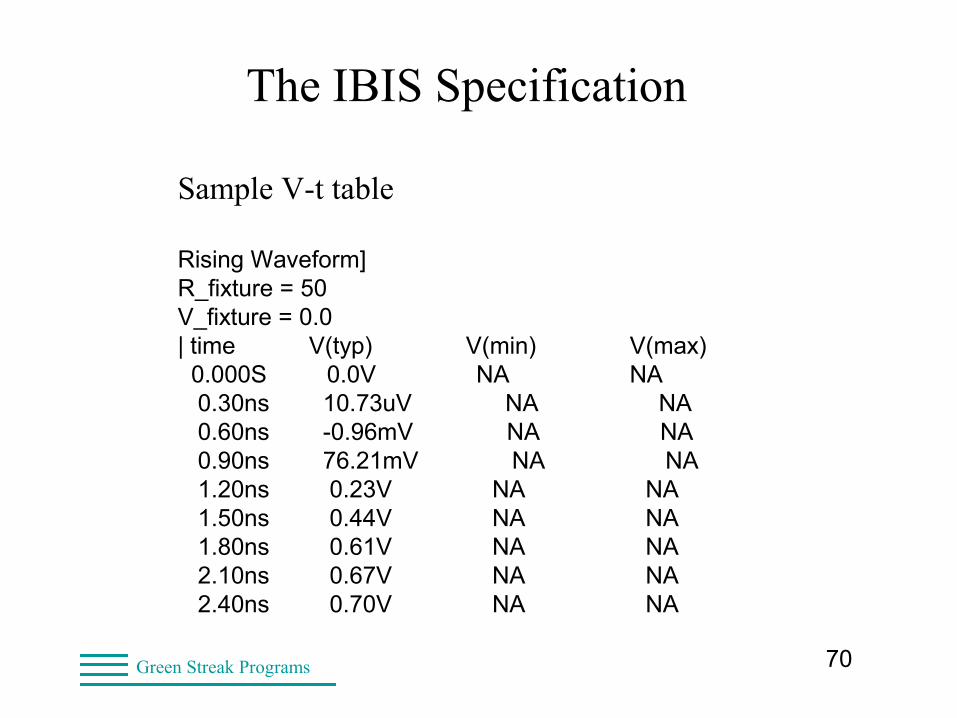
The IBIS Specification
Sample V-t table
Rising Waveform]R_fixture = 50V_fixture = 0.0| time V(typ) V(min) V(max) 0.000S 0.0V NA NA 0.30ns 10.73uV NA NA 0.60ns -0.96mV NA NA 0.90ns 76.21mV NA NA 1.20ns 0.23V NA NA 1.50ns 0.44V NA NA 1.80ns 0.61V NA NA 2.10ns 0.67V NA NA 2.40ns 0.70V NA NA
71Green Streak Programs
I/O Buffer Models
• Model used by one or more pins, on one or more components
• Model name is unique within the IBIS file
• 17 pre-defined model types
– Input, Output, I/O, 3-state, Open_sink, I/O_open_sink, Open_source, I/O_open_source, Input_ECL, Output_ECL, I/O_ECL, 3-state_ECL
– Series, Series_switch, Terminator
• IBIS 5.2 allows external model files
– SPICE 3f5, VHDL-AMS, Verilog-AMS, AMI

72Green Streak Programs
Creating IBIS Models• From SPICE
– Need SPICE familiarity
– Need SPICE transistor models
• From hardware
– Need to control I/O buffer (toggle)
– High speed probe techniques
– Format data to IBIS columns
73Green Streak Programs
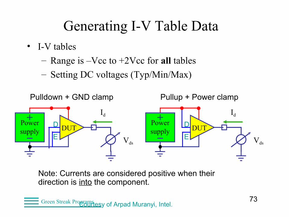
Generating I-V Table Data• I-V tables
– Range is –Vcc to +2Vcc for all tables
– Setting DC voltages (Typ/Min/Max)
Note: Currents are considered positive when their direction is into the component.
DUTPowersupply
Vds
Id
D
EDUT
Powersupply
Vds
Id
D
E
Pulldown + GND clamp Pullup + Power clamp
Courtesy of Arpad Muranyi, Intel.
74Green Streak Programs
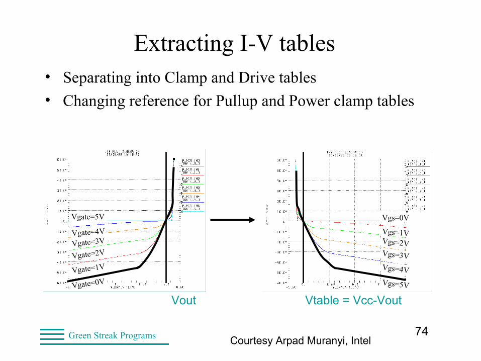
Extracting I-V tables• Separating into Clamp and Drive tables
• Changing reference for Pullup and Power clamp tables
Vgs=5V
Vgs=4V
Vgs=3V
Vgs=2V
Vgs=1V
Vgs=0V
Vgate=0V
Vgate=1VVgate=2VVgate=3VVgate=4V
Vgate=5V
Vout Vtable = Vcc-Vout
Courtesy Arpad Muranyi, Intel
75Green Streak Programs
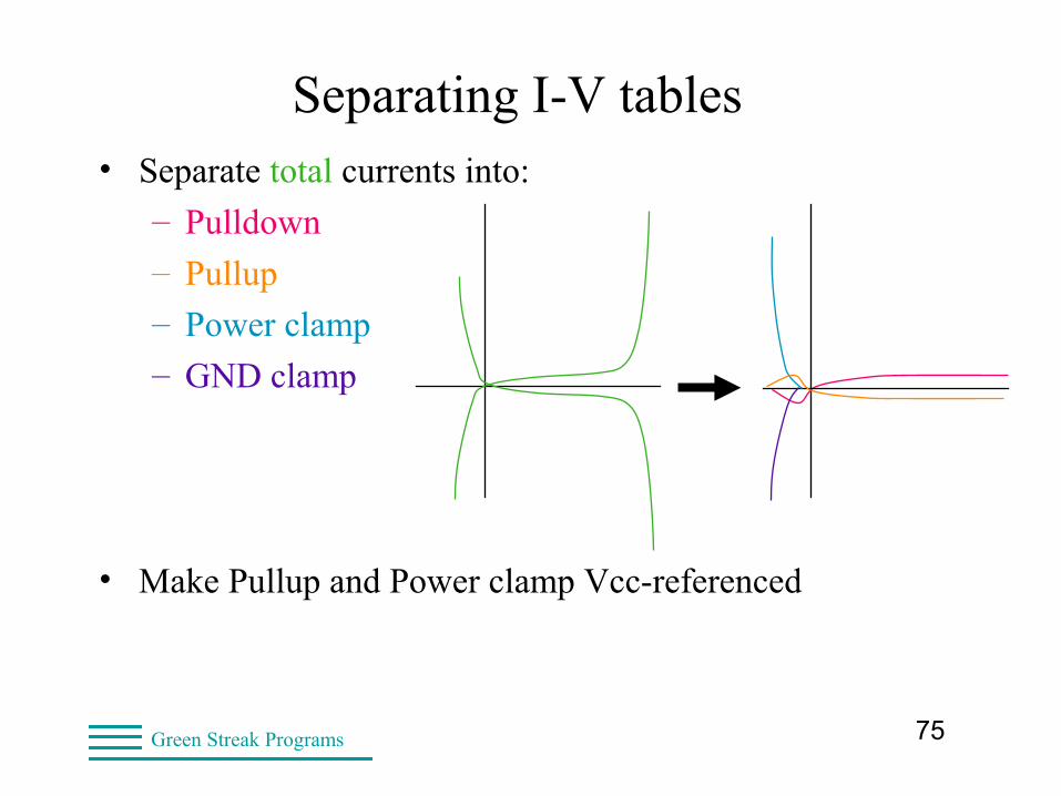
Separating I-V tables• Separate total currents into:
– Pulldown
– Pullup
– Power clamp
– GND clamp
• Make Pullup and Power clamp Vcc-referenced
76Green Streak Programs
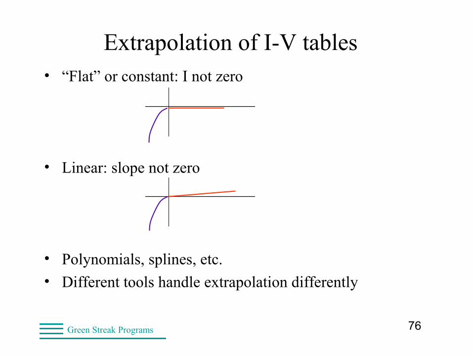
Extrapolation of I-V tables• “Flat” or constant: I not zero
• Linear: slope not zero
• Polynomials, splines, etc.
• Different tools handle extrapolation differently
77Green Streak Programs
Generating V-t Table Data• V-t tables
– Stop time => steady-state voltage reached
– Time step < 0.10 * Tedge
– Data step (Core edge rate) (Typ/Min/Max)
– Specified load (such as 50 Ohms)
– Resistive load. No ringing!
• Start and end times
– Start: signal from core into buffer toggles
– End: Just enough for Min signal to settle
78Green Streak Programs
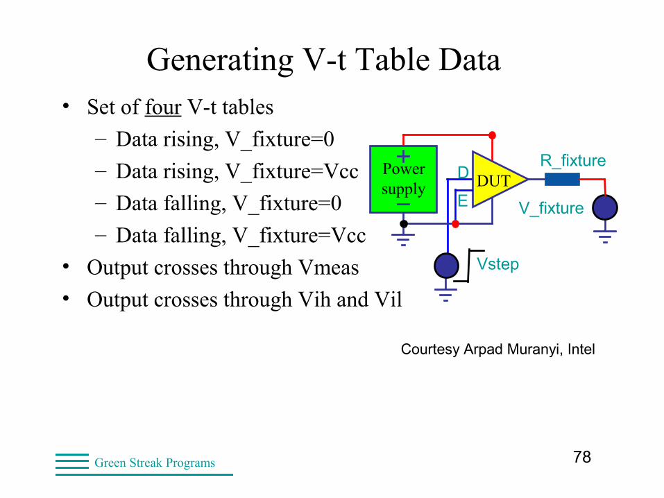
Generating V-t Table Data• Set of four V-t tables
– Data rising, V_fixture=0
– Data rising, V_fixture=Vcc
– Data falling, V_fixture=0
– Data falling, V_fixture=Vcc
• Output crosses through Vmeas
• Output crosses through Vih and Vil
DUTPowersupply
D
E
R_fixture
V_fixture
Vstep
Courtesy Arpad Muranyi, Intel
79Green Streak Programs
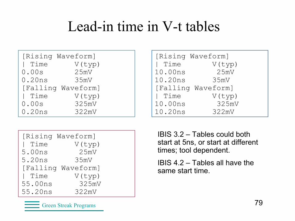
Lead-in time in V-t tables
[Rising Waveform]| Time V(typ) 0.00s 25mV0.20ns 35mV[Falling Waveform]| Time V(typ)0.00s 325mV0.20ns 322mV
[Rising Waveform]| Time V(typ) 10.00ns 25mV10.20ns 35mV[Falling Waveform]| Time V(typ)10.00ns 325mV10.20ns 322mV
[Rising Waveform]| Time V(typ) 5.00ns 25mV5.20ns 35mV[Falling Waveform]| Time V(typ)55.00ns 325mV55.20ns 322mV
IBIS 3.2 – Tables could both start at 5ns, or start at different times; tool dependent.
IBIS 4.2 – Tables all have the same start time.
80Green Streak Programs
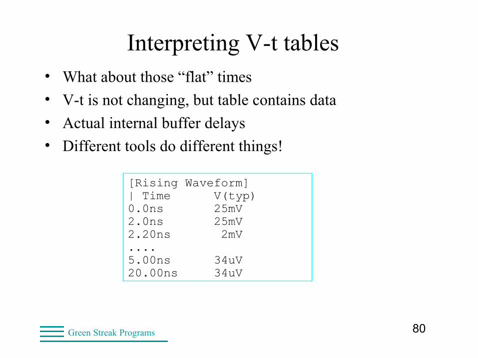
Interpreting V-t tables
[Rising Waveform]| Time V(typ) 0.0ns 25mV 2.0ns 25mV2.20ns 2mV....5.00ns 34uV20.00ns 34uV
• What about those “flat” times
• V-t is not changing, but table contains data
• Actual internal buffer delays
• Different tools do different things!
81Green Streak Programs
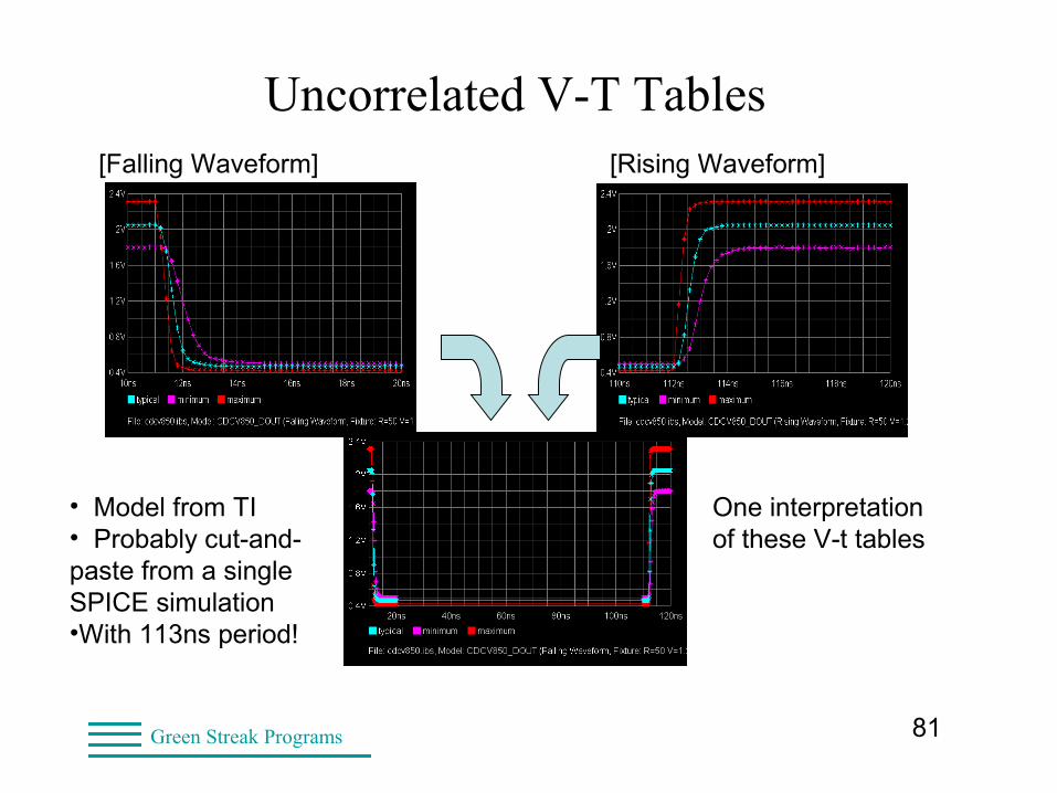
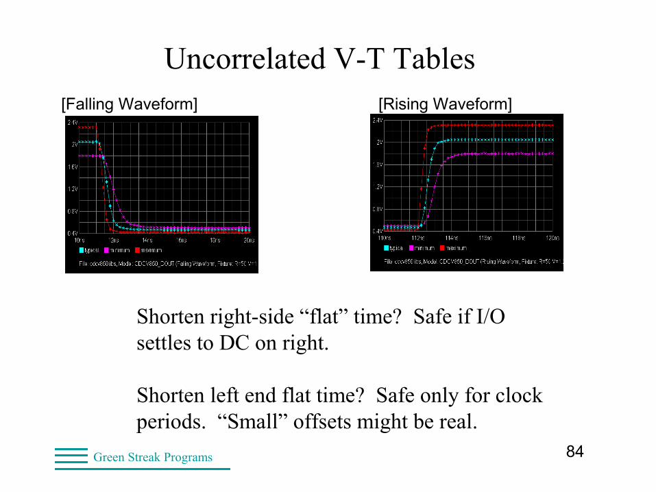
Uncorrelated V-T Tables[Falling Waveform] [Rising Waveform]
• Model from TI• Probably cut-and-paste from a single SPICE simulation•With 113ns period!
One interpretation of these V-t tables
82Green Streak Programs
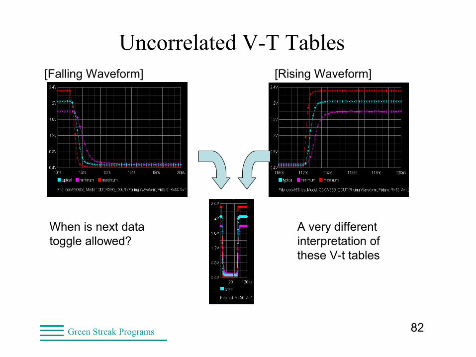
Uncorrelated V-T Tables[Falling Waveform] [Rising Waveform]
When is next data toggle allowed?
A very different interpretation of these V-t tables
83Green Streak Programs
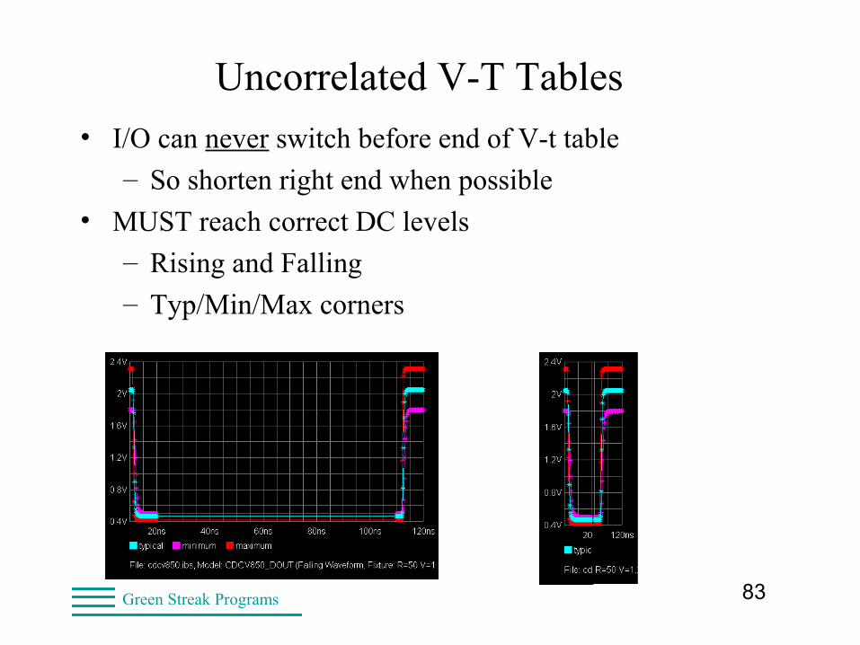
Uncorrelated V-T Tables• I/O can never switch before end of V-t table
– So shorten right end when possible
• MUST reach correct DC levels
– Rising and Falling
– Typ/Min/Max corners
84Green Streak Programs
Uncorrelated V-T Tables
Shorten right-side “flat” time? Safe if I/O settles to DC on right.
Shorten left end flat time? Safe only for clock periods. “Small” offsets might be real.
[Falling Waveform] [Rising Waveform]
85Green Streak Programs
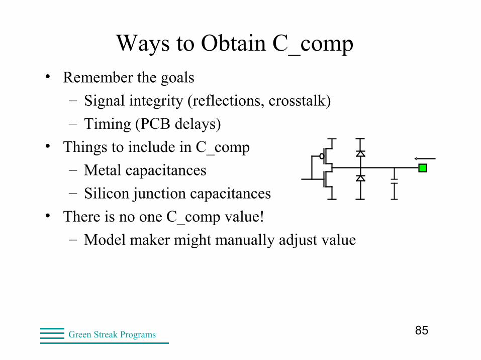
Ways to Obtain C_comp• Remember the goals
– Signal integrity (reflections, crosstalk)
– Timing (PCB delays)
• Things to include in C_comp
– Metal capacitances
– Silicon junction capacitances
• There is no one C_comp value!
– Model maker might manually adjust value
86Green Streak Programs
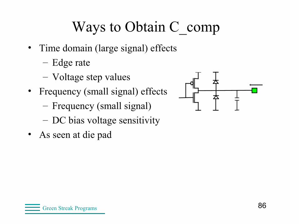
Ways to Obtain C_comp• Time domain (large signal) effects
– Edge rate
– Voltage step values
• Frequency (small signal) effects
– Frequency (small signal)
– DC bias voltage sensitivity
• As seen at die pad
87Green Streak Programs
Ways to Obtain C_comp• Splitting C_comp into four
– For gnd/power (PDS) bounce simulations
• One each to
– Vcc
– Power Clamp Reference
– GND
– GND Clamp Reference
• IBIS I-V tables driven by Vpad(t)
– Not Vcc(t) or [Vcc-Vpad](t)
– Some tools can get first-order solution
88Green Streak Programs
SPICE to IBIS Flow• Communication with model maker
• SPICE not shared
– Proprietary buffer design
– Proprietary process parameters
• many-way NDA is difficult
– SPICE I/O “Library
– Foundry process “Library”
– Package “Library”
– Rockwell Automation designs

89Green Streak Programs
SPICE to IBIS Flow• Done by model maker
• Set up SPICE input files
– One for each corner
– One for each I-V table
– One for each V-t table
• Set up SPICE I/O buffer file
– Pin order matches callout in SPICE files
– Buffer netlist
– Run SPICE
• Extract the data
90Green Streak Programs
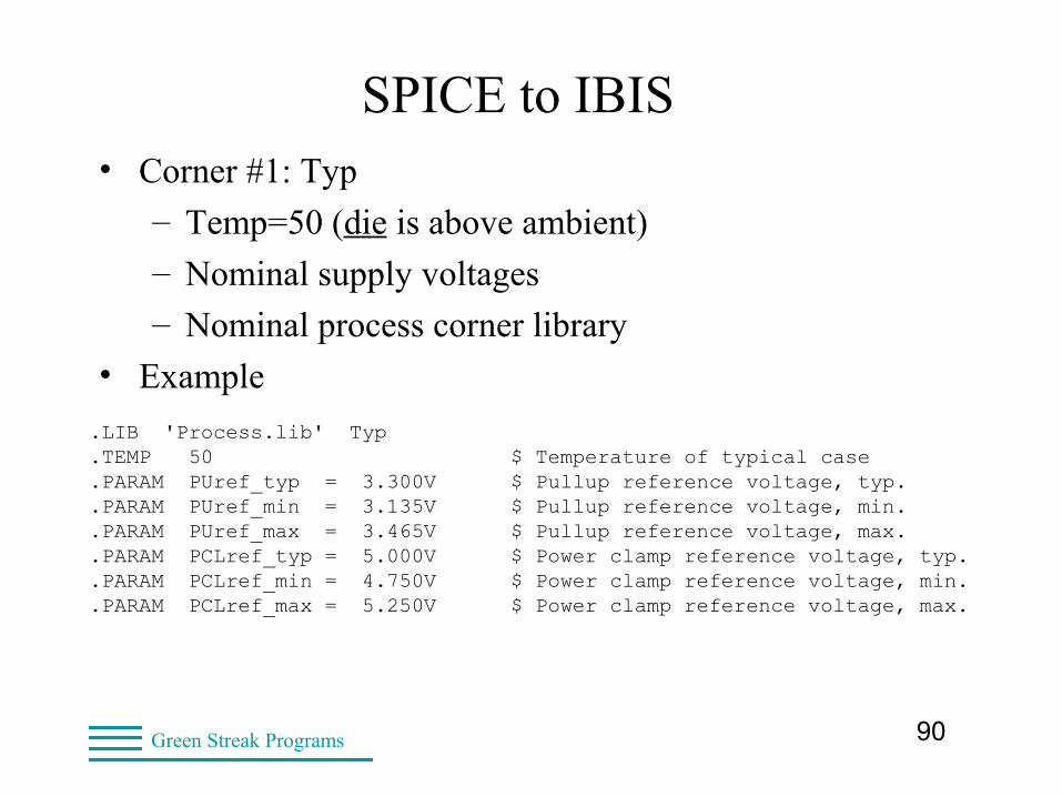
SPICE to IBIS• Corner #1: Typ
– Temp=50 (die is above ambient)
– Nominal supply voltages
– Nominal process corner library
• Example
.LIB 'Process.lib' Typ
.TEMP 50 $ Temperature of typical case
.PARAM PUref_typ = 3.300V $ Pullup reference voltage, typ.
.PARAM PUref_min = 3.135V $ Pullup reference voltage, min.
.PARAM PUref_max = 3.465V $ Pullup reference voltage, max.
.PARAM PCLref_typ = 5.000V $ Power clamp reference voltage, typ.
.PARAM PCLref_min = 4.750V $ Power clamp reference voltage, min.
.PARAM PCLref_max = 5.250V $ Power clamp reference voltage, max.
91Green Streak Programs
SPICE to IBIS• Set up the buffer loading
– R load, typically 50 ohms
– No L or C load
– No package load
• EDA tools use I-V and V-t tables
– Requires R load
– Generate I/O response to input data
– Generate I/O response to reflections
92Green Streak Programs
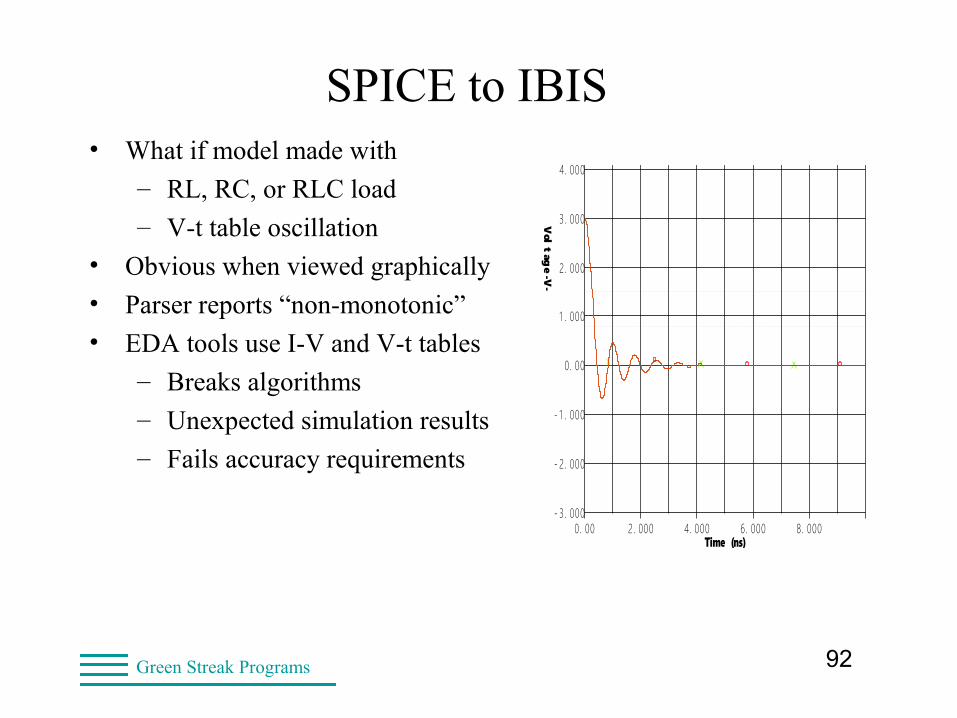
SPICE to IBIS• What if model made with
– RL, RC, or RLC load
– V-t table oscillation
• Obvious when viewed graphically
• Parser reports “non-monotonic”
• EDA tools use I-V and V-t tables
– Breaks algorithms
– Unexpected simulation results
– Fails accuracy requirements
OSCILLOSCOPEDesign file: LABS.FFS Designer: Lynne D. Green
HyperLynx V7.7
Date: Tuesday Sep. 18, 2007 Time: 22:33:18Show Latest Waveform = YES
- 3. 000
- 2. 000
- 1 . 000
0. 00
1 . 000
2. 000
3. 000
4. 000
5. 000
6. 000
0. 00 2. 000 4. 000 6. 000 8. 000Time (ns)
Vol
tag
e - V-
93Green Streak Programs
SPICE to IBIS• What model makers sometimes overlook
• Check output for errors and certain warnings
• Example:model ZZ parameter XX not found
– Indicates model mismatch (wrong library)
• Example:convergence failed
– Indicates results will be incomplete
– And an IBIS table will end too soon
94Green Streak Programs
IBIS Validation: Methodology• The latest IBIS Parser
• The IBIS Quality Checklist
• Visual check
• Simulation
• Validation and Verification http://www.eda.org/ibis/
95Green Streak Programs
IBIS Parsers• IBIS parser
– ibischk5 last updated Oct 2012
– Checks IBIS 3.2, 4.2, 5.1, etc.
– Checks EBD and PKG models
– New checks added in ibischk4 & ibischk5
• icmchk1
– Checks ICM models
• tschk2
– Checks Touchstone models
96Green Streak Programs
The IBIS Parser• ibischk5 is the latest
– Checks IBIS 3.2, 4.2, 5.1, etc.
– Many new checks added in ibischk5
– Parser bug fixes
• Parser catches many common problems
– Syntax (keywords, capitalization, etc)
• Basic data checks
– Missing data
– Nonmonotonic data
– Table endpoint mismatch
97Green Streak Programs
The IBIS Quality Checklist• IBIS Quality Checklist Items
– About 100 items
– Some are fairly common
– Some are rare (special I/O types)
• THE Number One Problem
– Model not checked with latest IBIS Parser!
• Data extraction issues
– I-V and V-t tables
– C_comp
• Model not simulated in any tool
98Green Streak Programs
Recognizing Common Problems• Failure to pass IBIS parser
• Unexpected glitches in I-V tables
• Incomplete V-t tables
• Not enough I-V or V-t points
– 10 points in transition regions
• Not all data used (tool dependent)
– Model selector does not work
– Only first four V-t tables used
• Missing Vmeas (needed by ICX)
99Green Streak Programs
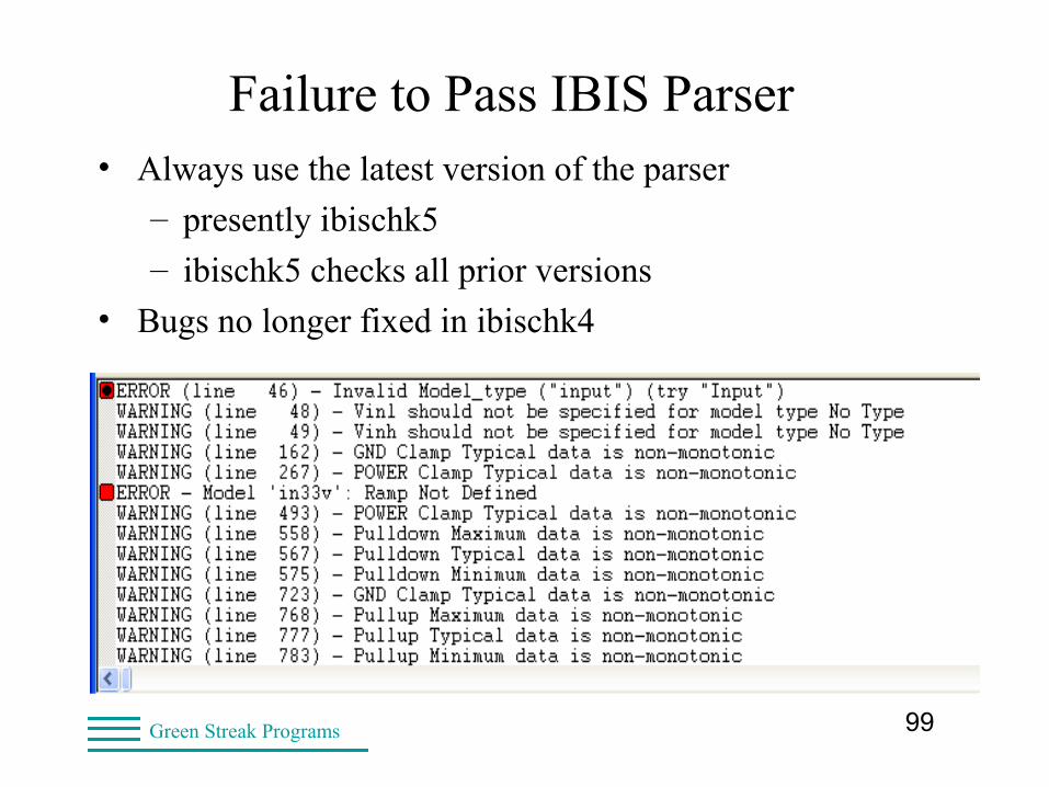
Failure to Pass IBIS Parser• Always use the latest version of the parser
– presently ibischk5
– ibischk5 checks all prior versions
• Bugs no longer fixed in ibischk4
100Green Streak Programs
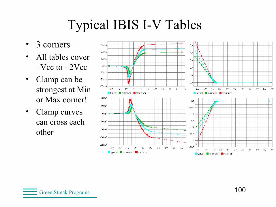
Typical IBIS I-V Tables• 3 corners• All tables cover
–Vcc to +2Vcc
• Clamp can be strongest at Min or Max corner!
• Clamp curves can cross each other
101Green Streak Programs
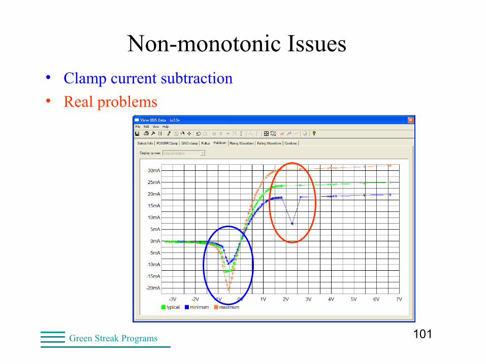
Non-monotonic Issues• Clamp current subtraction
• Real problems
102Green Streak Programs
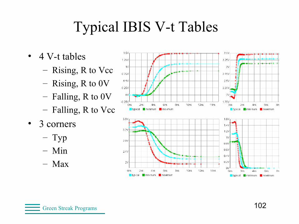
Typical IBIS V-t Tables
• 4 V-t tables– Rising, R to Vcc
– Rising, R to 0V
– Falling, R to 0V
– Falling, R to Vcc
• 3 corners– Typ
– Min
– Max
103Green Streak Programs
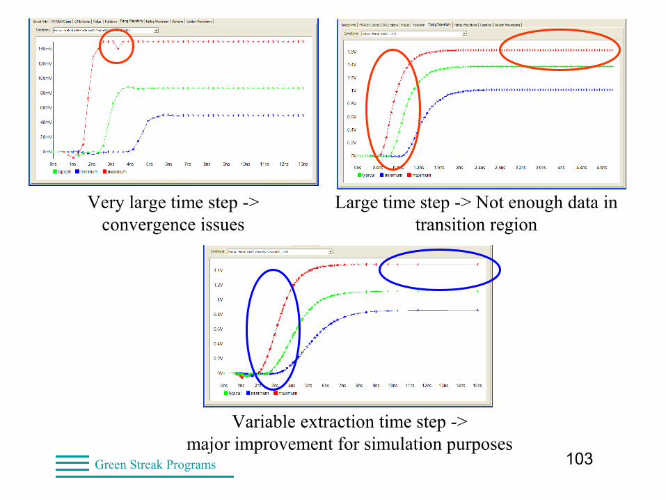
Variable extraction time step ->major improvement for simulation purposes
Very large time step -> convergence issues
Large time step -> Not enough data in transition region
104Green Streak Programs
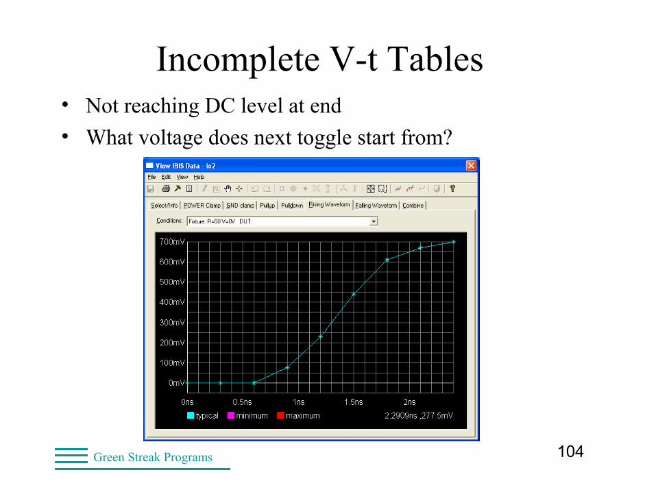
Incomplete V-t Tables• Not reaching DC level at end
• What voltage does next toggle start from?
105Green Streak Programs
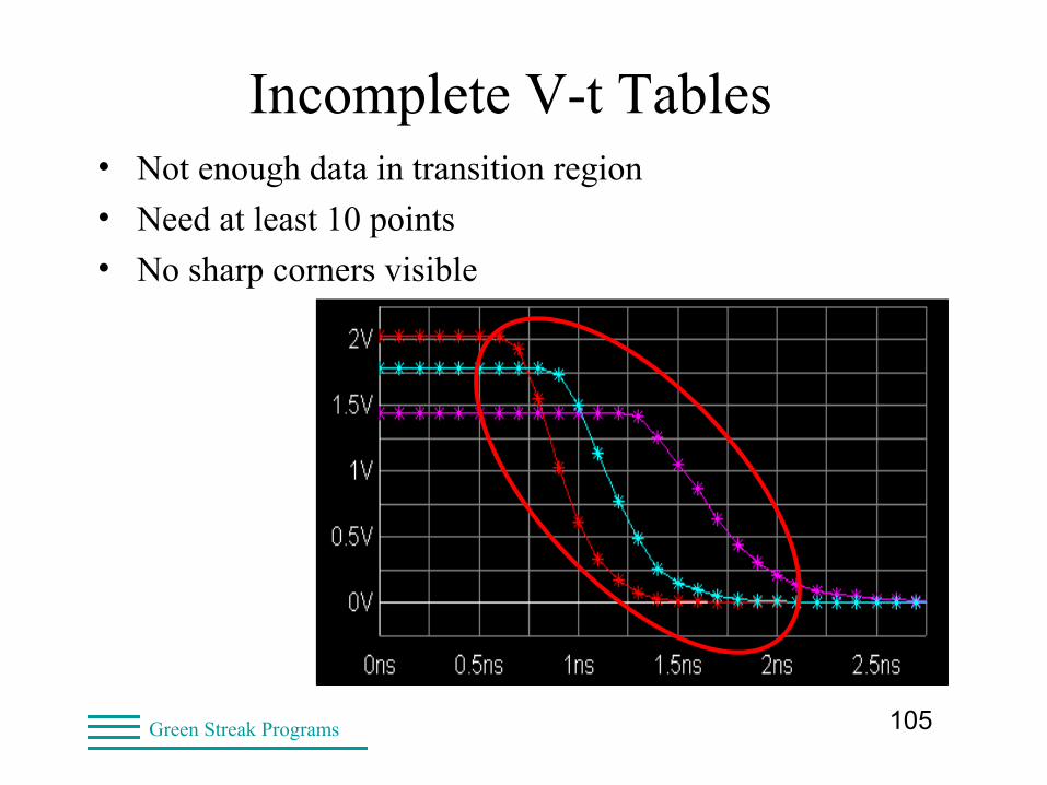
Incomplete V-t Tables• Not enough data in transition region
• Need at least 10 points
• No sharp corners visible
106Green Streak Programs
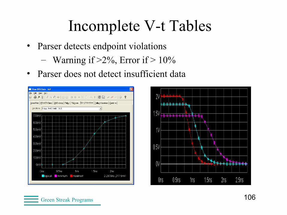
Incomplete V-t Tables• Parser detects endpoint violations
– Warning if >2%, Error if > 10%
• Parser does not detect insufficient data
107Green Streak Programs
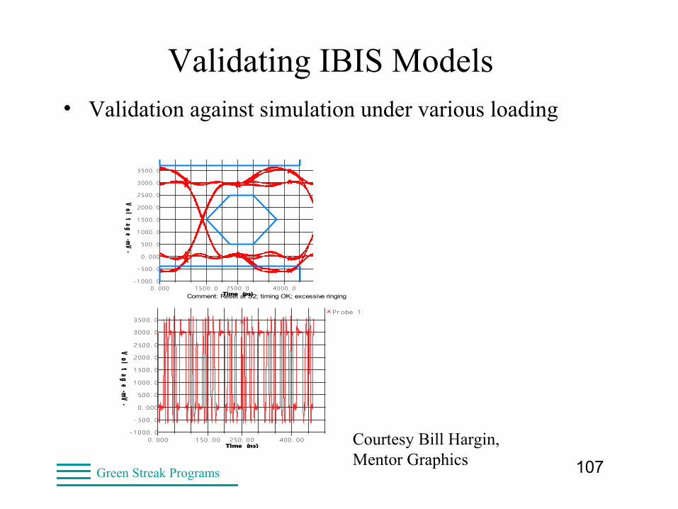
Validating IBIS Models• Validation against simulation under various loading
OSCILLOSCOPEDesign file: DEMO.HYP Designer: Lynne D. Green
HyperLynx V7.5Comment: Reset at S2; timing OK; excessive ringing
Date: Wednesday Nov. 2, 2005 Time: 13:39:27Net name: reset
- 1 000. 0
- 500. 0
0. 000
500. 0
1 000. 0
1 500. 0
2000. 0
2500. 0
3000. 0
3500. 0
0. 000 1 500. 0 2500. 0 4000. 0Time (ps)
Vol
tag
e -mV-
OSCILLOSCOPEDesign file: DEMO.HYP Designer: Lynne D. Green
HyperLynx V7.5Comment: Reset at S2; timing OK; excessive ringing
Date: Wednesday Nov. 2, 2005 Time: 13:40:35Net name: reset
Show Latest Waveform = YES
- 1 000. 0
- 500. 0
0. 000
500. 0
1 000. 0
1 500. 0
2000. 0
2500. 0
3000. 0
3500. 0
0. 000 1 50. 00 250. 00 400. 00Time (ns)
Vol
tag
e -mV-
Pr obe 1 : S2. 2 ( at pi n)
Courtesy Bill Hargin, Mentor Graphics
108Green Streak Programs
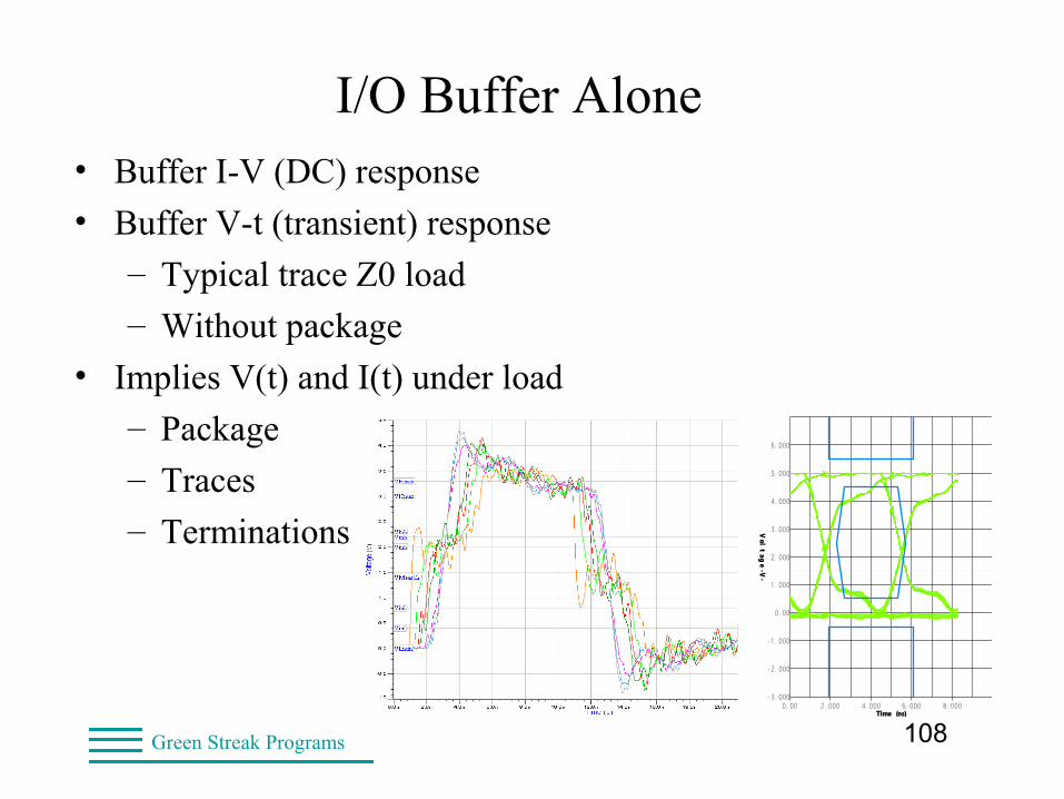
I/O Buffer Alone• Buffer I-V (DC) response
• Buffer V-t (transient) response
– Typical trace Z0 load
– Without package
• Implies V(t) and I(t) under load
– Package
– Traces
– Terminations
OSCILLOSCOPEDesign file: CLOCKFIX.TLN Designer: Lynne D. Green
HyperLynx V7.7Comment: Termination fixes EYE problem
Date: Tuesday Aug. 7, 2007 Time: 22:18:19
- 3. 000
- 2. 000
- 1 . 000
0. 00
1 . 000
2 . 000
3 . 000
4. 000
5 . 000
6 . 000
0. 00 2. 000 4. 000 6. 000 8. 000Time (ns)
Vol
tag
e - V-
109Green Streak Programs
How Vendors Compare SPICE and IBIS• Ideally: Overlay SPICE and IBIS and Test Data
• Overlay SPICE
– Model built from SPICE => 100% match
– So rarely look at results, just ship the model
• End user flow:
– Verify IBIS models (and incidentally SPICE models)
– Overlay simulation and test data
– Verify methodology
– Check limits of IBIS simulation
110Green Streak Programs
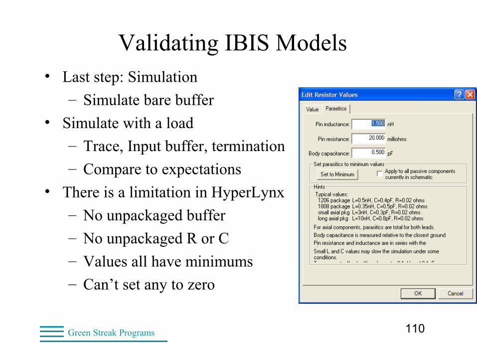
Validating IBIS Models• Last step: Simulation
– Simulate bare buffer
• Simulate with a load
– Trace, Input buffer, termination
– Compare to expectations
• There is a limitation in HyperLynx
– No unpackaged buffer
– No unpackaged R or C
– Values all have minimums
– Can’t set any to zero
111Green Streak Programs
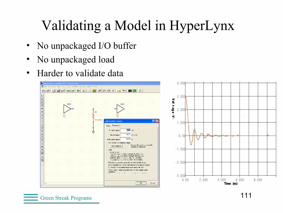
Validating a Model in HyperLynx• No unpackaged I/O buffer
• No unpackaged load
• Harder to validate data
OSCILLOSCOPEDesign file: LABS.FFS Designer: Lynne D. Green
HyperLynx V7.7
Date: Tuesday Sep. 18, 2007 Time: 22:33:18Show Latest Waveform = YES
- 3. 000
- 2. 000
- 1 . 000
0. 00
1 . 000
2. 000
3. 000
4. 000
5. 000
6. 000
0. 00 2. 000 4. 000 6. 000 8. 000Time (ns)
Vol
tag
e - V-
112Green Streak Programs
Validate, Then Verify• Validation checks model against IBIS specification
– Sanity checks on data
– IBIS always agrees with its source data
• Verification checks data against hardware
– Requires having hardware
– Check selected nets (signal quality, delays)
• Closing the loop
– Makes it easier to debug when problems occur
– Validates IBIS design flow and methodology
113Green Streak Programs
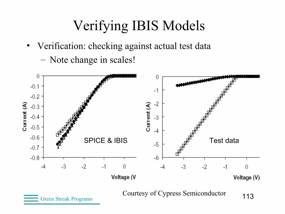
Verifying IBIS Models• Verification: checking against actual test data
– Note change in scales!
Courtesy of Cypress Semiconductor
Test dataSPICE & IBIS
114Green Streak Programs
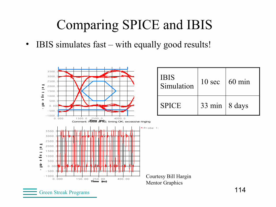
Comparing SPICE and IBIS• IBIS simulates fast – with equally good results!
IBIS Simulation
10 sec 60 min
SPICE 33 min 8 days
OSCILLOSCOPEDesign file: DEMO.HYP Designer: Lynne D. Green
HyperLynx V7.5Comment: Reset at S2; timing OK; excessive ringing
Date: Wednesday Nov. 2, 2005 Time: 13:39:27Net name: reset
- 1 000 . 0
- 500 . 0
0 . 000
500. 0
1 000 . 0
1 500 . 0
2000. 0
2500. 0
3000. 0
3500. 0
0. 000 1 500. 0 2500. 0 4000. 0Time (ps)
Vol
tag
e -mV-
OSCILLOSCOPEDesign file: DEMO.HYP Designer: Lynne D. Green
HyperLynx V7.5Comment: Reset at S2; timing OK; excessive ringing
Date: Wednesday Nov. 2, 2005 Time: 13:40:35Net name: reset
Show Latest Waveform = YES
- 1 000. 0
- 500. 0
0. 000
500. 0
1 000. 0
1 500. 0
2000. 0
2500. 0
3000. 0
3500. 0
0. 000 1 50. 00 250. 00 400 . 00Time (ns)
Vol
tag
e -mV-
Pr obe 1 : S2. 2 ( a t pi n)
Courtesy Bill HarginMentor Graphics
115Green Streak Programs
Comparing SPICE and IBIS• Overlay SPICE and IBIS and Test Data
• Overlay SPICE
– Rarely look at results, just ship the model
– Users might do this for critical paths
• Overlay Test Data
– Verify model
– Verify methodology
– Check limits of IBIS simulation
116Green Streak Programs
Data During Validation• Some EDA tools use FIRST MODEL under [Model Selector]
– This is default operation
– Specify different selection by rearranging models
– Might need more than one file
• One for each [Model Selector] option
• Some EDA tools use only FIRST FOUR V-t tables
– Specify different selection by rearranging models
– Rarely need more than one file
– Unless I/O can drive a very wide range of Z0 loads
117Green Streak Programs
The IBIS Quality Checklist• Incorporated various checklists
– Model reviewers
– Model makers and model users
• Checks for syntax, structure, data
• Examples:
– Header ([File Name], [File Rev] etc.)
– Component ([Pin], [Diff Pin], etc.)
– Model (Tables, C_comp, etc.)
118Green Streak Programs
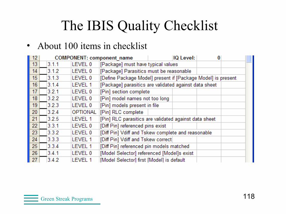
The IBIS Quality Checklist• About 100 items in checklist
119Green Streak Programs
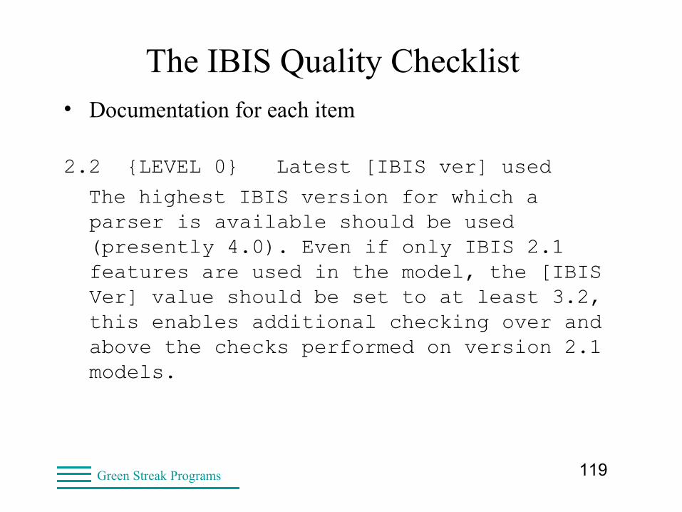
The IBIS Quality Checklist• Documentation for each item
2.2 {LEVEL 0} Latest [IBIS ver] used
The highest IBIS version for which a parser is available should be used (presently 4.0). Even if only IBIS 2.1 features are used in the model, the [IBIS Ver] value should be set to at least 3.2, this enables additional checking over and above the checks performed on version 2.1 models.
120Green Streak Programs
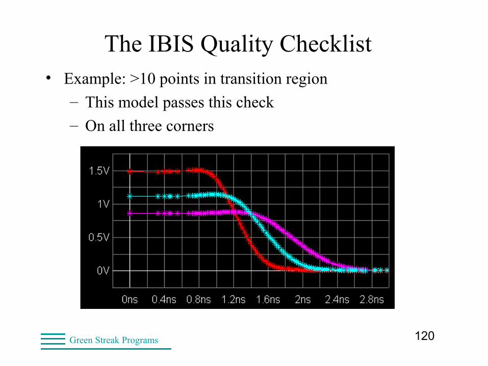
The IBIS Quality Checklist• Example: >10 points in transition region
– This model passes this check
– On all three corners

121Green Streak Programs
The IBIS Quality Checklist• Example: >10 points in transition region
– This model would not pass this check
– MAX corner fails
122Green Streak Programs
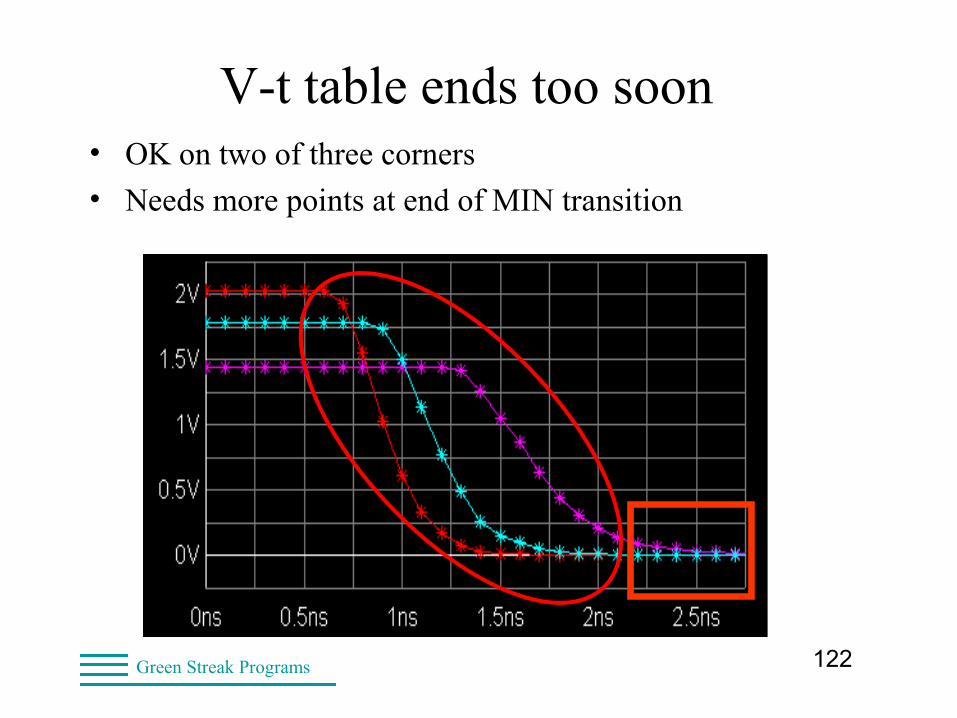
V-t table ends too soon• OK on two of three corners
• Needs more points at end of MIN transition
123Green Streak Programs
The IBIS Quality Checklist• Requirements which can be checked by IBIS parser.
– Use of ibischk5 is highly recommended.
• Documented in an Quality Summary
• ALL IBISCHK Errors must be explained
– Unavoidable ones in some specialty models
– Check with model maker if not documented
• IBISCHK warnings should be explained
– Ideally, no warnings
– Some warnings cannot be eliminated
124Green Streak Programs
The IBIS Quality Checklist
125Green Streak Programs
The IBIS Quality Checklist• All pins defined and validated
– correct logical/physical/model mapping.
• All package parasitics checked.
• Model selectors validated.
• [Diff Pins] validated.
• C_comp values checked.
• All model spec waveforms and load parameters defined and validated.
• Ramp Data validated
126Green Streak Programs
The IBIS Quality Checklist• Ramp data validated against V-T tables
• V-T tables defined for all output drivers
• All I-V and V-T tables visually inspected
• Typ/Min/Max values must be present
– in correct order for all tables and parameters
• All output models must be simulated
– into standard load
– switch through VMEAS
• All receiver models must be simulated
– Smooth Vinl to/from Vinh
127Green Streak Programs
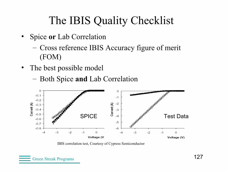
The IBIS Quality Checklist• Spice or Lab Correlation
– Cross reference IBIS Accuracy figure of merit (FOM)
• The best possible model
– Both Spice and Lab Correlation
IBIS correlation test, Courtesy of Cypress Semiconductor
SPICE Test Data
128Green Streak Programs
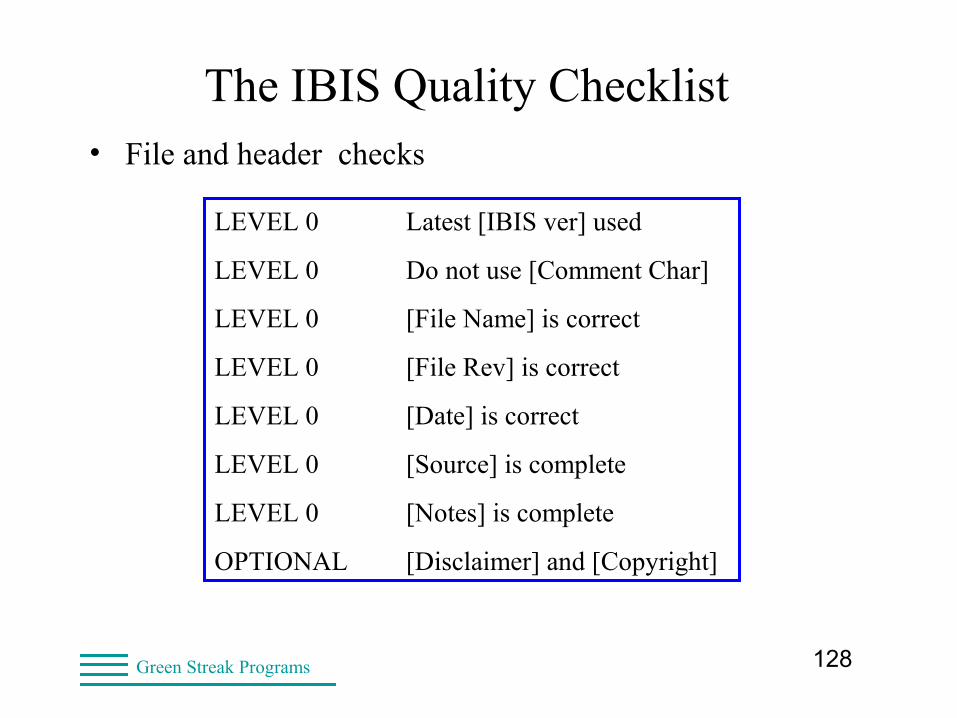
The IBIS Quality Checklist• File and header checks
LEVEL 0 Latest [IBIS ver] used
LEVEL 0 Do not use [Comment Char]
LEVEL 0 [File Name] is correct
LEVEL 0 [File Rev] is correct
LEVEL 0 [Date] is correct
LEVEL 0 [Source] is complete
LEVEL 0 [Notes] is complete
OPTIONAL [Disclaimer] and [Copyright]
129Green Streak Programs
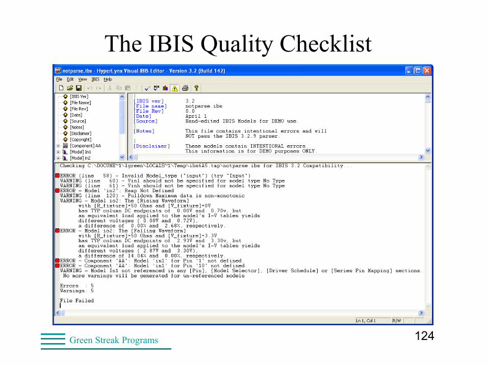
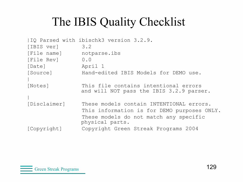
The IBIS Quality Checklist|IQ Parsed with ibischk3 version 3.2.9.[IBIS ver] 3.2[File name] notparse.ibs[File Rev] 0.0 [Date] April 1[Source] Hand-edited IBIS Models for DEMO use.|[Notes] This file contains intentional errors
and will NOT pass the IBIS 3.2.9 parser.|[Disclaimer] These models contain INTENTIONAL errors. This information is for DEMO purposes ONLY. These models do not match any specific
physical parts.[Copyright] Copyright Green Streak Programs 2004
130Green Streak Programs
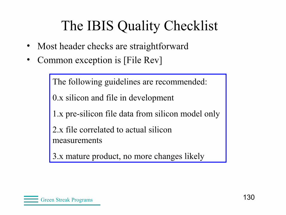
The IBIS Quality Checklist• Most header checks are straightforward
• Common exception is [File Rev]
The following guidelines are recommended:
0.x silicon and file in development
1.x pre-silicon file data from silicon model only
2.x file correlated to actual silicon measurements
3.x mature product, no more changes likely
131Green Streak Programs
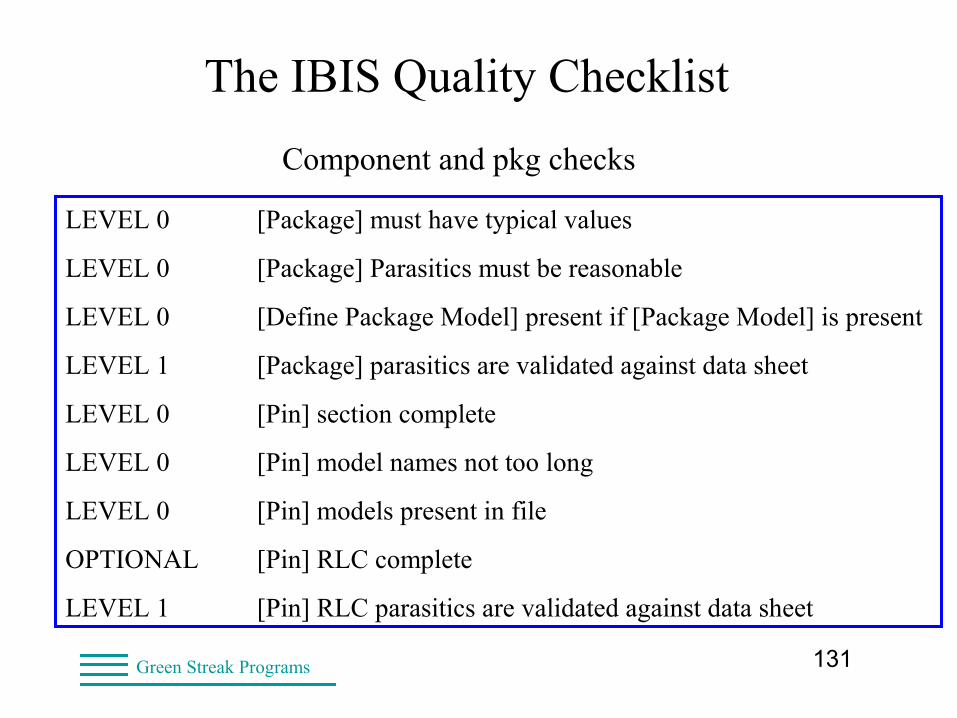
The IBIS Quality Checklist
Component and pkg checks
LEVEL 0 [Package] must have typical values
LEVEL 0 [Package] Parasitics must be reasonable
LEVEL 0 [Define Package Model] present if [Package Model] is present
LEVEL 1 [Package] parasitics are validated against data sheet
LEVEL 0 [Pin] section complete
LEVEL 0 [Pin] model names not too long
LEVEL 0 [Pin] models present in file
OPTIONAL [Pin] RLC complete
LEVEL 1 [Pin] RLC parasitics are validated against data sheet
132Green Streak Programs
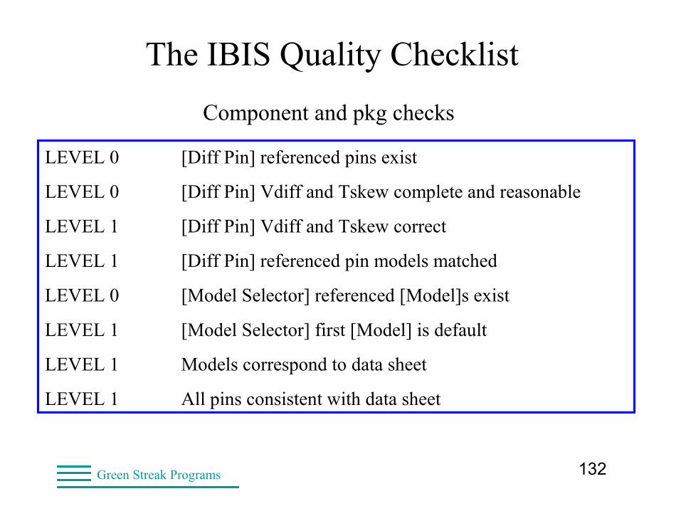
The IBIS Quality Checklist
Component and pkg checks
LEVEL 0 [Diff Pin] referenced pins exist
LEVEL 0 [Diff Pin] Vdiff and Tskew complete and reasonable
LEVEL 1 [Diff Pin] Vdiff and Tskew correct
LEVEL 1 [Diff Pin] referenced pin models matched
LEVEL 0 [Model Selector] referenced [Model]s exist
LEVEL 1 [Model Selector] first [Model] is default
LEVEL 1 Models correspond to data sheet
LEVEL 1 All pins consistent with data sheet

133Green Streak Programs
The IBIS Quality Checklist[Component] AA
[Manufacturer] None
[Package]
| variable typ min max
R_pkg 1f NA NA
L_pkg 1f NA NA
C_pkg 1f NA NA
[Pin] signal_name model_name R_pin L_pin C_pin
1 A1 in1
2 Y1 in2
3 Y1 in3
4 Y2 io1
5 Y3 io2
6 A2 io3
7 Dummy NC
8 GND GND
9 VCC POWER
10 A3 in1
134Green Streak Programs
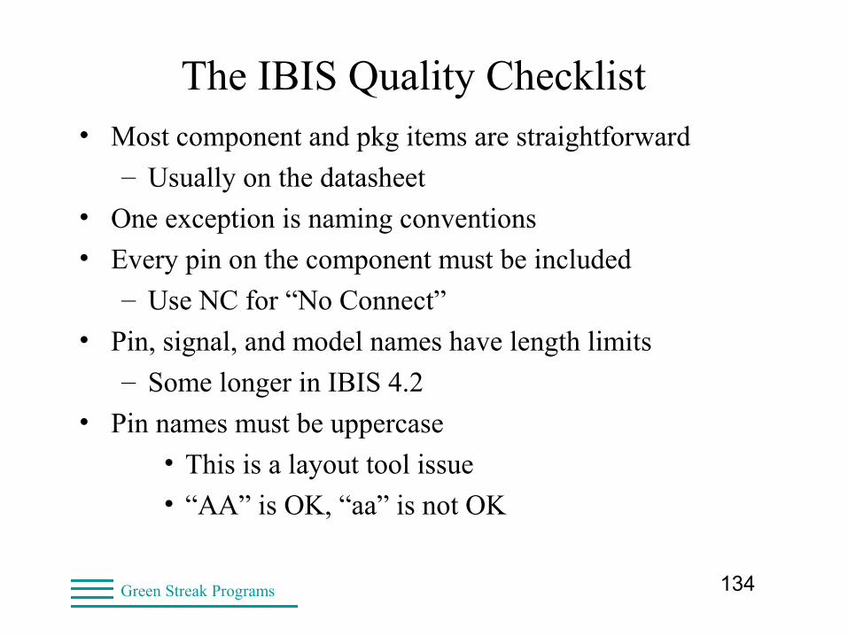
The IBIS Quality Checklist• Most component and pkg items are straightforward
– Usually on the datasheet
• One exception is naming conventions
• Every pin on the component must be included
– Use NC for “No Connect”
• Pin, signal, and model names have length limits
– Some longer in IBIS 4.2
• Pin names must be uppercase
• This is a layout tool issue
• “AA” is OK, “aa” is not OK
135Green Streak Programs
The IBIS Quality Checklist• I/O model checks
– Not ordered by IQ level
– Organized by where things occur
– Or things that are closely related
• The greatest number of checks
• The most important for simulation
136Green Streak Programs
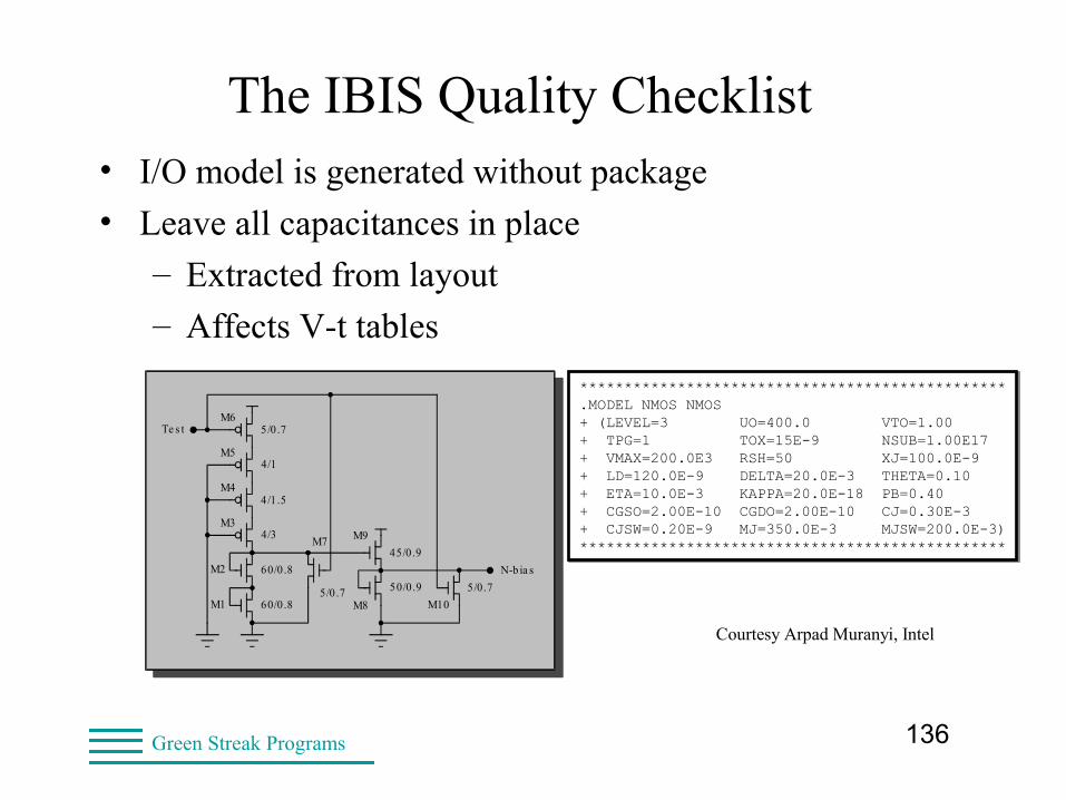
The IBIS Quality Checklist• I/O model is generated without package
• Leave all capacitances in place
– Extracted from layout
– Affects V-t tables
************************************************.MODEL NMOS NMOS+ (LEVEL=3 UO=400.0 VTO=1.00+ TPG=1 TOX=15E-9 NSUB=1.00E17+ VMAX=200.0E3 RSH=50 XJ=100.0E-9+ LD=120.0E-9 DELTA=20.0E-3 THETA=0.10+ ETA=10.0E-3 KAPPA=20.0E-18 PB=0.40+ CGSO=2.00E-10 CGDO=2.00E-10 CJ=0.30E-3+ CJSW=0.20E-9 MJ=350.0E-3 MJSW=200.0E-3)************************************************
************************************************.MODEL NMOS NMOS+ (LEVEL=3 UO=400.0 VTO=1.00+ TPG=1 TOX=15E-9 NSUB=1.00E17+ VMAX=200.0E3 RSH=50 XJ=100.0E-9+ LD=120.0E-9 DELTA=20.0E-3 THETA=0.10+ ETA=10.0E-3 KAPPA=20.0E-18 PB=0.40+ CGSO=2.00E-10 CGDO=2.00E-10 CJ=0.30E-3+ CJSW=0.20E-9 MJ=350.0E-3 MJSW=200.0E-3)************************************************
Te s t
N-b ia s
5/0.7
4/1
4/1.5
4/3
60/0.8
60/0.85/0.7
45/0.9
50/0.9 5/0.7
M1
M2
M3
M4
M5
M6
M7
M8
M9
M10
Te s t
N-b ia s
5/0.7
4/1
4/1.5
4/3
60/0.8
60/0.85/0.7
45/0.9
50/0.9 5/0.7
M1
M2
M3
M4
M5
M6
M7
M8
M9
M10
Courtesy Arpad Muranyi, Intel
137Green Streak Programs
The IBIS Quality Checklist [Model]
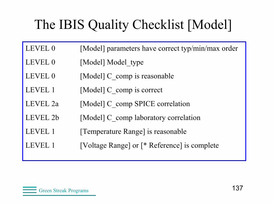
LEVEL 0 [Model] parameters have correct typ/min/max order
LEVEL 0 [Model] Model_type
LEVEL 0 [Model] C_comp is reasonable
LEVEL 1 [Model] C_comp is correct
LEVEL 2a [Model] C_comp SPICE correlation
LEVEL 2b [Model] C_comp laboratory correlation
LEVEL 1 [Temperature Range] is reasonable
LEVEL 1 [Voltage Range] or [* Reference] is complete

138Green Streak Programs
The IBIS Quality Checklist [Model][Model] io1Model_type I/OPolarity Non-Inverting|Vinl = 0.8V Vinh = 2.0V Vmeas = 1.5V Cref = 10.0pFRref = 100Vref = 0.0V | typ min maxC_comp 8.0pF 4.0pF 16.0pF[Voltage Range] 3.30V 3.0V 3.6V[Temperature Range] 50.0 0.00 100.00
139Green Streak Programs
The IBIS Quality Checklist [Model]• Notes on [Temperature Range]
• Must account for self-heating of chip
– “TYP” is not 25 Centigrade!
– 50 Centigrade is typical
• Same for Min and Max
• This affects design margins!

140Green Streak Programs
The IBIS Quality Checklist [Model]• What is C_comp?
– Does not include package capacitance
– Determines reflections at die pad
• Represents only on-die capacitance
– Connected to the output pad
– Silicon junctions and gates
• (FETs, ESD structures, diodes)
– Metal (interconnects to pad)
– Pad stack structure
141Green Streak Programs
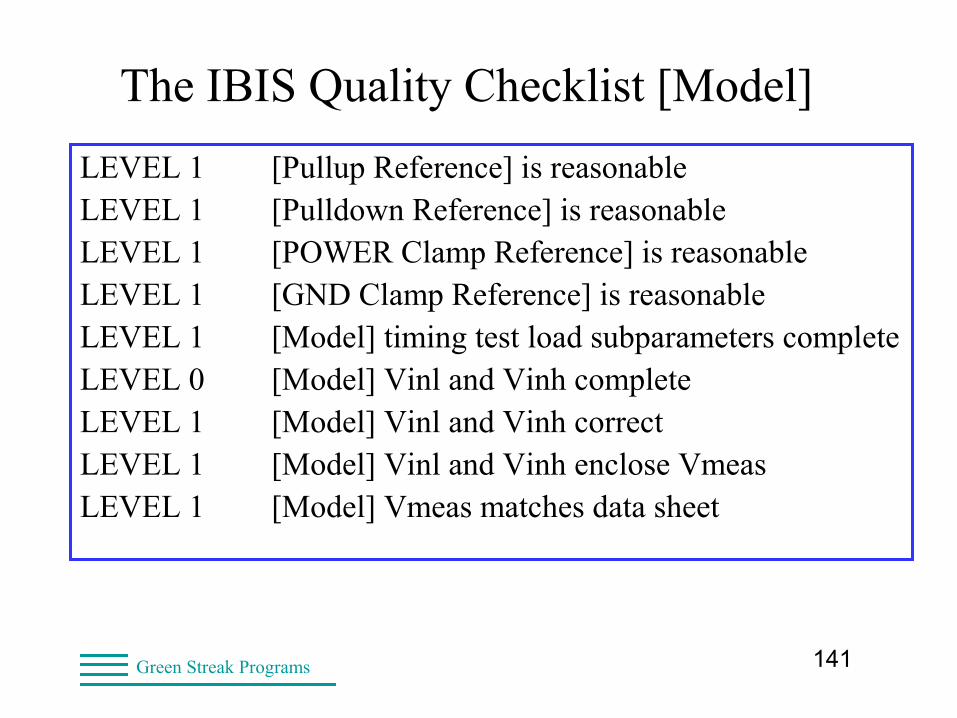
The IBIS Quality Checklist [Model]
LEVEL 1 [Pullup Reference] is reasonableLEVEL 1 [Pulldown Reference] is reasonableLEVEL 1 [POWER Clamp Reference] is reasonableLEVEL 1 [GND Clamp Reference] is reasonableLEVEL 1 [Model] timing test load subparameters completeLEVEL 0 [Model] Vinl and Vinh completeLEVEL 1 [Model] Vinl and Vinh correctLEVEL 1 [Model] Vinl and Vinh enclose VmeasLEVEL 1 [Model] Vmeas matches data sheet
142Green Streak Programs
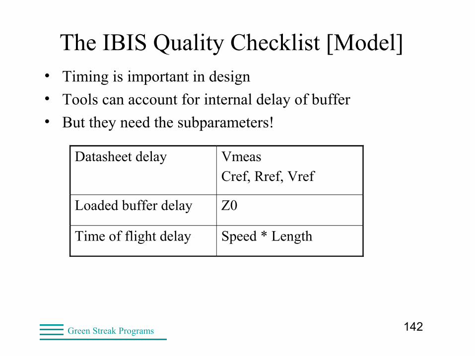
The IBIS Quality Checklist [Model]• Timing is important in design
• Tools can account for internal delay of buffer
• But they need the subparameters!
Datasheet delay VmeasCref, Rref, Vref
Loaded buffer delay Z0
Time of flight delay Speed * Length
143Green Streak Programs
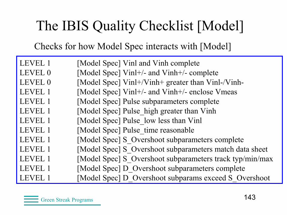
The IBIS Quality Checklist [Model]Checks for how Model Spec interacts with [Model]
LEVEL 1 [Model Spec] Vinl and Vinh completeLEVEL 0 [Model Spec] Vinl+/- and Vinh+/- completeLEVEL 0 [Model Spec] Vinl+/Vinh+ greater than Vinl-/Vinh-LEVEL 1 [Model Spec] Vinl+/- and Vinh+/- enclose VmeasLEVEL 1 [Model Spec] Pulse subparameters completeLEVEL 1 [Model Spec] Pulse_high greater than VinhLEVEL 1 [Model Spec] Pulse_low less than VinlLEVEL 1 [Model Spec] Pulse_time reasonableLEVEL 1 [Model Spec] S_Overshoot subparameters completeLEVEL 1 [Model Spec] S_Overshoot subparameters match data sheetLEVEL 1 [Model Spec] S_Overshoot subparameters track typ/min/maxLEVEL 1 [Model Spec] D_Overshoot subparameters completeLEVEL 1 [Model Spec] D_Overshoot subparams exceed S_Overshoot
144Green Streak Programs
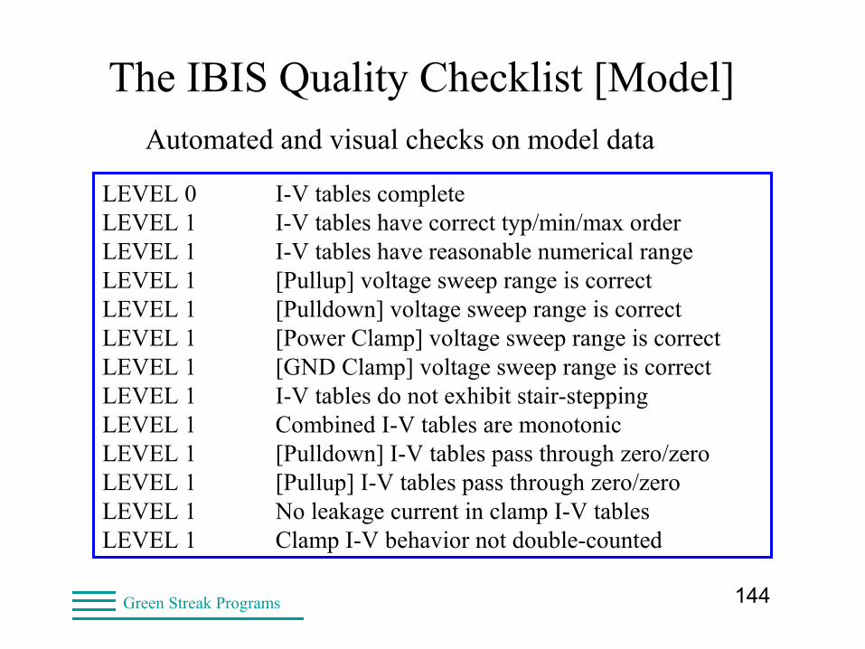
The IBIS Quality Checklist [Model]Automated and visual checks on model data
LEVEL 0 I-V tables completeLEVEL 1 I-V tables have correct typ/min/max orderLEVEL 1 I-V tables have reasonable numerical rangeLEVEL 1 [Pullup] voltage sweep range is correctLEVEL 1 [Pulldown] voltage sweep range is correctLEVEL 1 [Power Clamp] voltage sweep range is correctLEVEL 1 [GND Clamp] voltage sweep range is correctLEVEL 1 I-V tables do not exhibit stair-steppingLEVEL 1 Combined I-V tables are monotonicLEVEL 1 [Pulldown] I-V tables pass through zero/zeroLEVEL 1 [Pullup] I-V tables pass through zero/zeroLEVEL 1 No leakage current in clamp I-V tablesLEVEL 1 Clamp I-V behavior not double-counted

145Green Streak Programs
Moderately Good Clamp I-V Data
It would be better if these extended over full range of -3.3 to +6.6V, since different tools might extrapolate differently.
virtex4.ibs
146Green Streak Programs
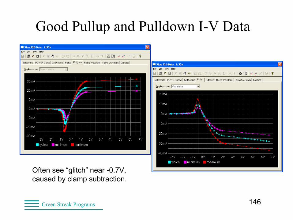
Good Pullup and Pulldown I-V Data
Often see “glitch” near -0.7V, caused by clamp subtraction.
147Green Streak Programs
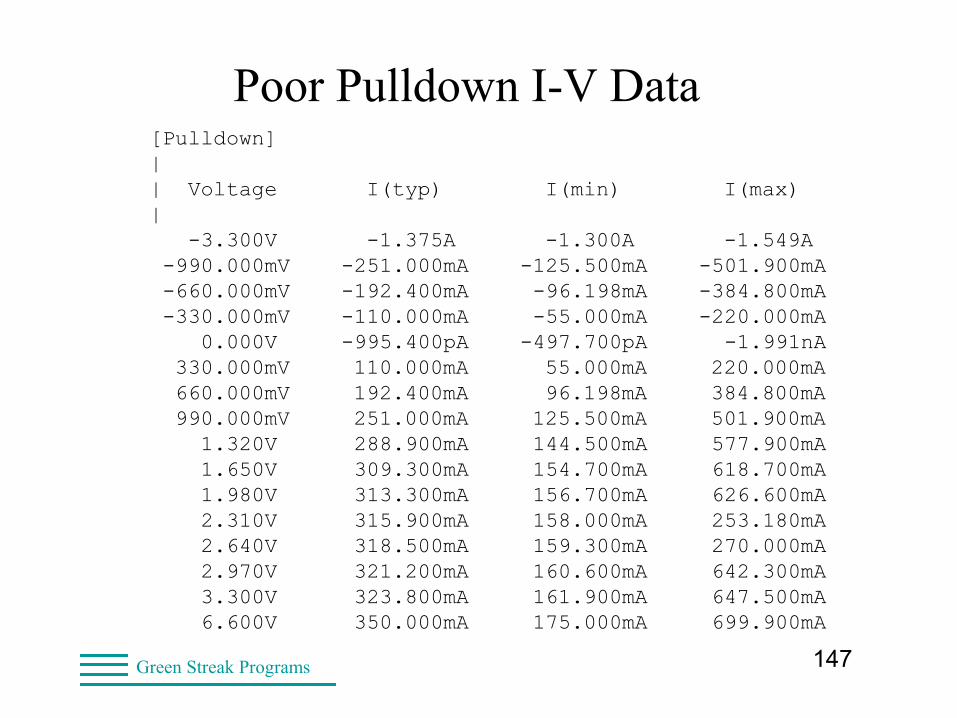
Poor Pulldown I-V Data[Pulldown]|| Voltage I(typ) I(min) I(max)| -3.300V -1.375A -1.300A -1.549A -990.000mV -251.000mA -125.500mA -501.900mA -660.000mV -192.400mA -96.198mA -384.800mA -330.000mV -110.000mA -55.000mA -220.000mA 0.000V -995.400pA -497.700pA -1.991nA 330.000mV 110.000mA 55.000mA 220.000mA 660.000mV 192.400mA 96.198mA 384.800mA 990.000mV 251.000mA 125.500mA 501.900mA 1.320V 288.900mA 144.500mA 577.900mA 1.650V 309.300mA 154.700mA 618.700mA 1.980V 313.300mA 156.700mA 626.600mA 2.310V 315.900mA 158.000mA 253.180mA 2.640V 318.500mA 159.300mA 270.000mA 2.970V 321.200mA 160.600mA 642.300mA 3.300V 323.800mA 161.900mA 647.500mA 6.600V 350.000mA 175.000mA 699.900mA
148Green Streak Programs
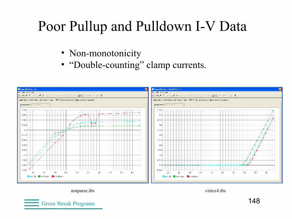
Poor Pullup and Pulldown I-V Data
• Non-monotonicity• “Double-counting” clamp currents.
virtex4.ibsnotparse.ibs
149Green Streak Programs
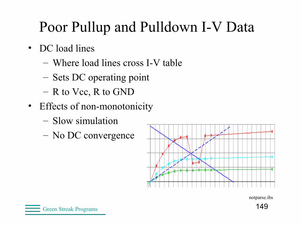
Poor Pullup and Pulldown I-V Data• DC load lines
– Where load lines cross I-V table
– Sets DC operating point
– R to Vcc, R to GND
• Effects of non-monotonicity
– Slow simulation
– No DC convergence
notparse.ibs
150Green Streak Programs
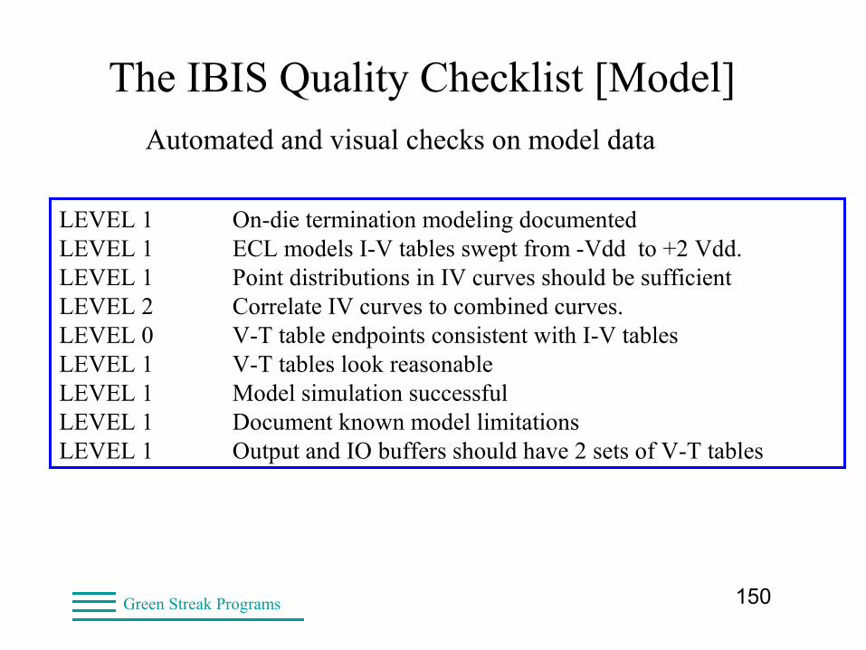
The IBIS Quality Checklist [Model]Automated and visual checks on model data
LEVEL 1 On-die termination modeling documentedLEVEL 1 ECL models I-V tables swept from -Vdd to +2 Vdd.LEVEL 1 Point distributions in IV curves should be sufficientLEVEL 2 Correlate IV curves to combined curves.LEVEL 0 V-T table endpoints consistent with I-V tablesLEVEL 1 V-T tables look reasonableLEVEL 1 Model simulation successfulLEVEL 1 Document known model limitationsLEVEL 1 Output and IO buffers should have 2 sets of V-T tables
151Green Streak Programs
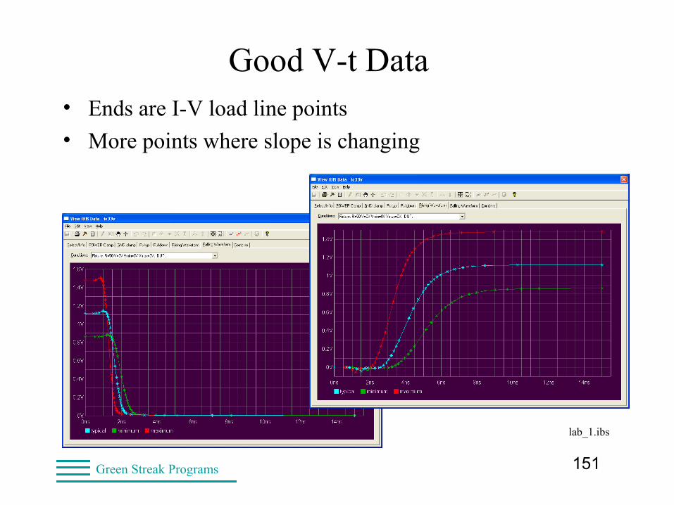
Good V-t Data• Ends are I-V load line points
• More points where slope is changing
lab_1.ibs
152Green Streak Programs
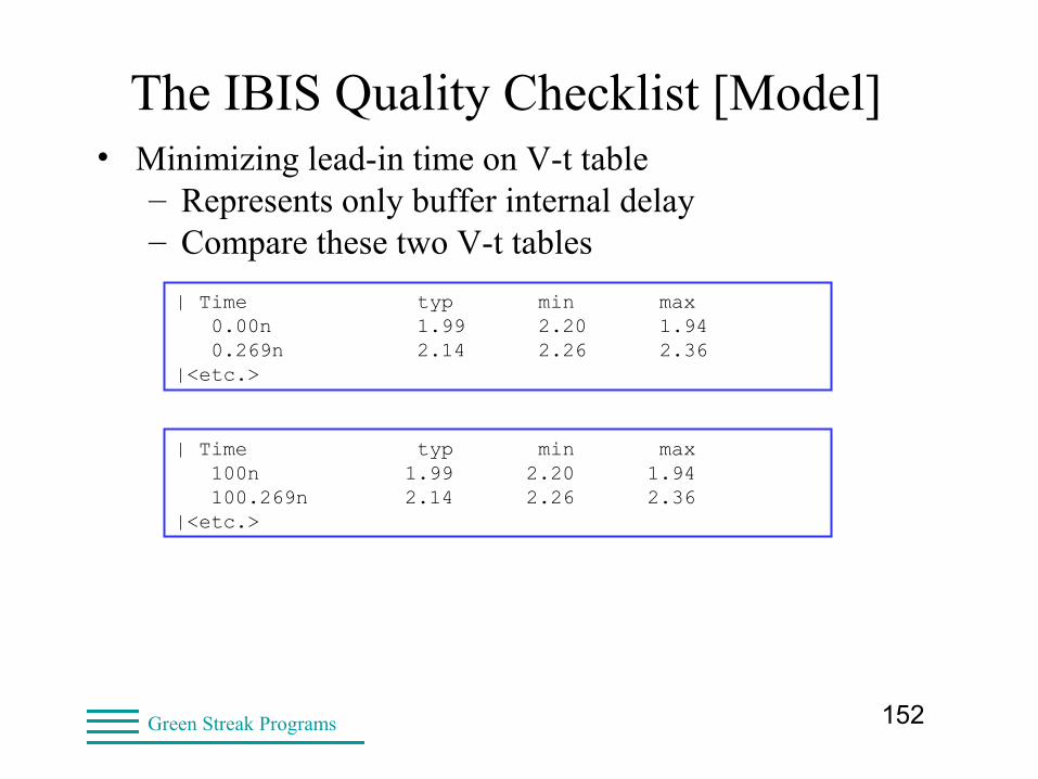
The IBIS Quality Checklist [Model]• Minimizing lead-in time on V-t table
– Represents only buffer internal delay– Compare these two V-t tables
| Time typ min max 0.00n 1.99 2.20 1.94 0.269n 2.14 2.26 2.36|<etc.>
| Time typ min max 100n 1.99 2.20 1.94 100.269n 2.14 2.26 2.36|<etc.>
153Green Streak Programs
Poor V-t data
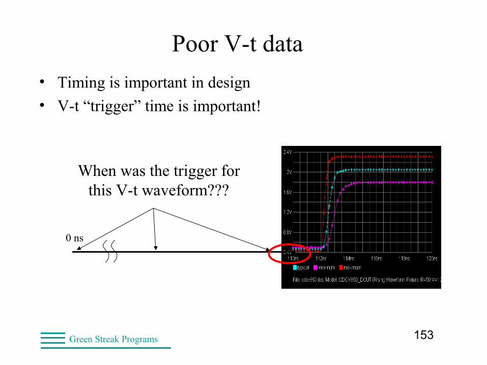
• Timing is important in design
• V-t “trigger” time is important!
0 ns
When was the trigger for this V-t waveform???
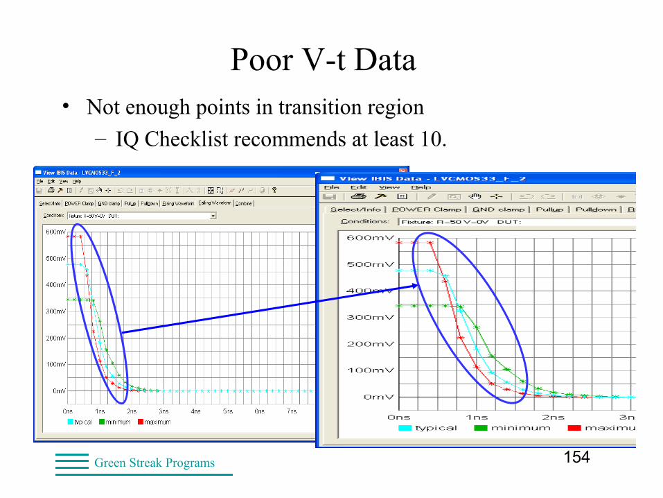
154Green Streak Programs
Poor V-t Data• Not enough points in transition region
– IQ Checklist recommends at least 10.
155Green Streak Programs
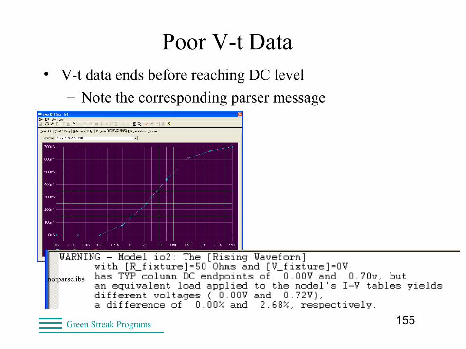
Poor V-t Data• V-t data ends before reaching DC level
– Note the corresponding parser message
notparse.ibs

156Green Streak Programs
The IBIS Quality Checklist [Model]Automated and visual checks on [Ramp] data
LEVEL 0 Output and IO buffers have a [Ramp] sectionLEVEL 1 [Ramp] R_load present if value other than 50 ohmsLEVEL 1 [Ramp] test fixture has no reactivesLEVEL 1 [Ramp] typ/min/max order is correctLEVEL 1 [Ramp] data dv and dt values positiveLEVEL 1 [Ramp] dv consistent with supply voltagesLEVEL 1 [Ramp] dv consistent with V-T table endpointsLEVEL 1 [Ramp] dt is consistent with 20%-80% crossing timeLEVEL 1 [Ramp] dt is consistent with data sheet
157Green Streak Programs
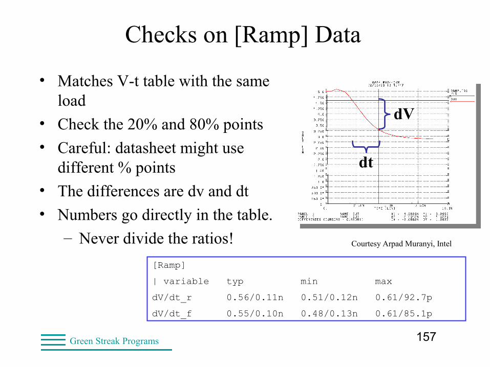
Checks on [Ramp] Data
• Matches V-t table with the same load
• Check the 20% and 80% points
• Careful: datasheet might use different % points
• The differences are dv and dt
• Numbers go directly in the table.
– Never divide the ratios!
dV
dt
[Ramp]
| variable typ min max
dV/dt_r 0.56/0.11n 0.51/0.12n 0.61/92.7p
dV/dt_f 0.55/0.10n 0.48/0.13n 0.61/85.1p
Courtesy Arpad Muranyi, Intel
158Green Streak Programs
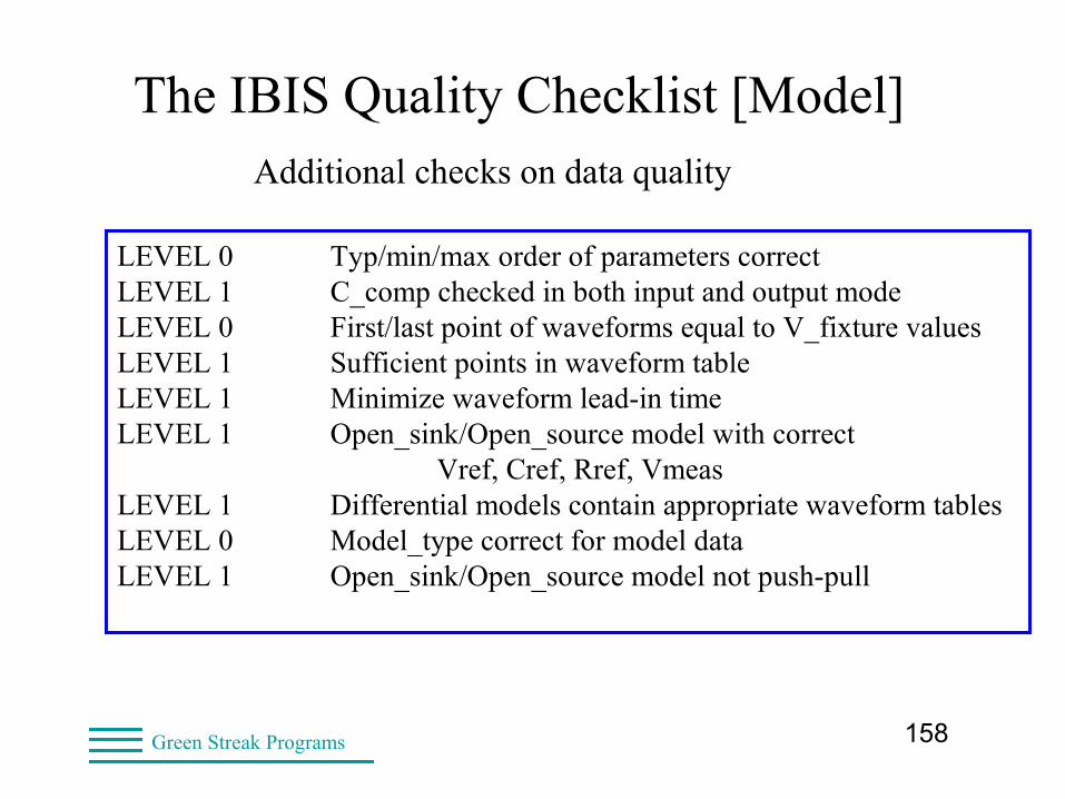
The IBIS Quality Checklist [Model]Additional checks on data quality
LEVEL 0 Typ/min/max order of parameters correctLEVEL 1 C_comp checked in both input and output modeLEVEL 0 First/last point of waveforms equal to V_fixture valuesLEVEL 1 Sufficient points in waveform tableLEVEL 1 Minimize waveform lead-in timeLEVEL 1 Open_sink/Open_source model with correct
Vref, Cref, Rref, VmeasLEVEL 1 Differential models contain appropriate waveform tablesLEVEL 0 Model_type correct for model dataLEVEL 1 Open_sink/Open_source model not push-pull
159Green Streak Programs
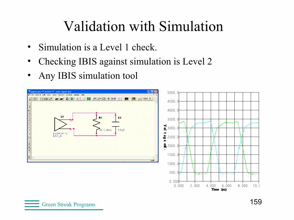
Validation with Simulation
OSCILLOSCOPEDesign file: LAST_FIGURE.FFS Designer: Lynne Green
BoardSim/LineSim, HyperLynx
Date: Thursday Mar. 10, 2005 Time: 15:29:09Show Latest Waveform = YES
0. 000
500. 0
1 000. 0
1 500. 0
2000. 0
2500. 0
3000. 0
3500. 0
4000. 0
4500. 0
5000. 0
0. 000 2. 000 4. 000 6. 000 8. 000 1 0. 000Time (ns)
Vol
tag
e -mV-
• Simulation is a Level 1 check.
• Checking IBIS against simulation is Level 2
• Any IBIS simulation tool
160Green Streak Programs
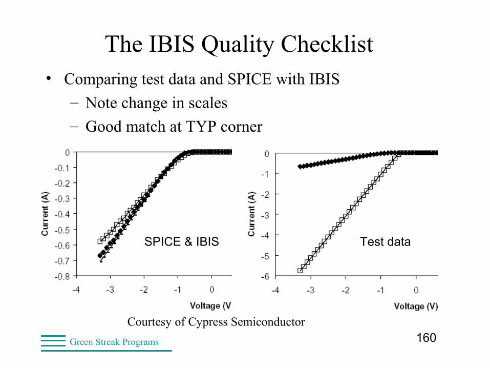
The IBIS Quality Checklist• Comparing test data and SPICE with IBIS
– Note change in scales
– Good match at TYP corner
Courtesy of Cypress Semiconductor
Test dataSPICE & IBIS

161Green Streak Programs
The IBIS Quality Checklist• What effects have you seen?
• Have they been captured in the checklist?
• Committee is still active
– Quality levels
– Documentation
• IBIS models and files appearing
– Documented Quality checks
162Green Streak Programs
IBIS Validation Methodology• Parse (ibischk5)
• View tables graphically
• Other IBIS Quality checks
• Simulate with any simulator
– Ones that customers use
• Release for internal design use
• Close the loop!

163Green Streak Programs
IBIS Validation MethodologyFor HyperLynx
• Run latest parser version on command line
• Inside VisIBIS Editor
– View tables graphically
– Other IBIS Quality checks
• With HyperLynx/LineSim
– Simulation
– Compare to expected results
– Compare to prototype hardware
164Green Streak Programs
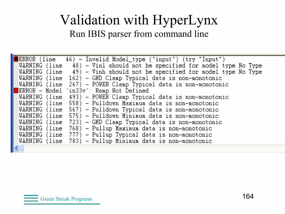
Validation with HyperLynxRun IBIS parser from command line
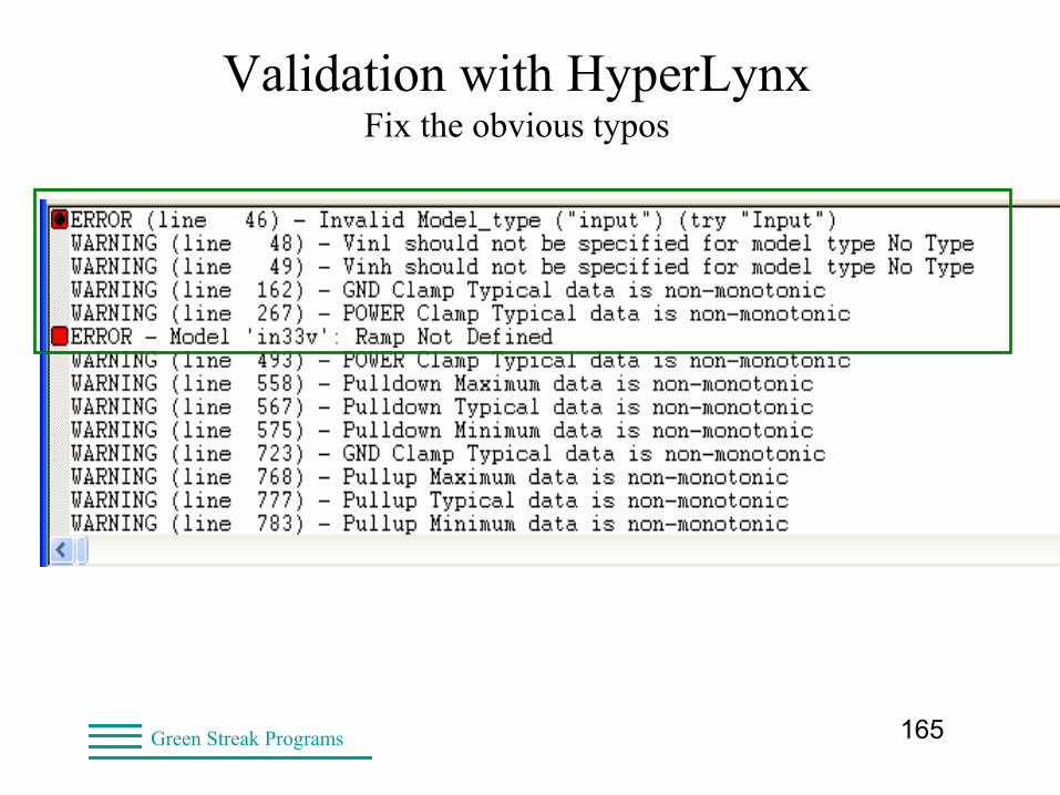
165Green Streak Programs
Validation with HyperLynxFix the obvious typos
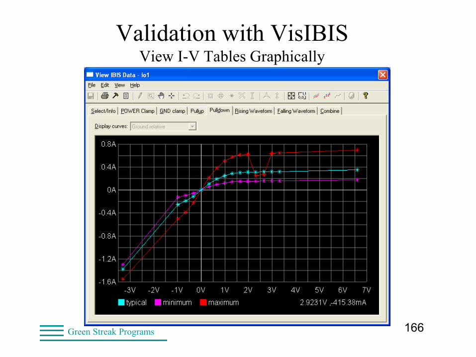
166Green Streak Programs
Validation with VisIBISView I-V Tables Graphically
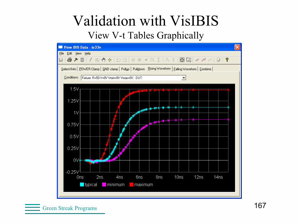
167Green Streak Programs
Validation with VisIBISView V-t Tables Graphically
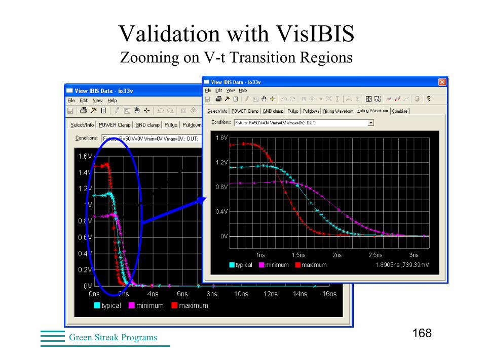
168Green Streak Programs
Validation with VisIBISZooming on V-t Transition Regions
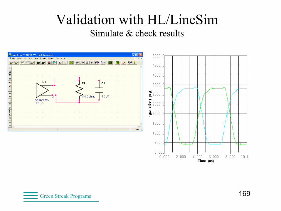
169Green Streak Programs
Validation with HL/LineSimSimulate & check results OSCILLOSCOPE
Design file: LAST_FIGURE.FFS Designer: Lynne GreenBoardSim/LineSim, HyperLynx
Date: Thursday Mar. 10, 2005 Time: 15:29:09Show Latest Waveform = YES
0. 000
500. 0
1 000. 0
1 500. 0
2000. 0
2500. 0
3000. 0
3500. 0
4000. 0
4500. 0
5000. 0
0. 000 2. 000 4. 000 6. 000 8. 000 1 0. 000Time (ns)
Vol
tag
e -mV-
170Green Streak Programs
High-speed Modeling Techniques
• Datasheet information
– Pin and model assignment
– Operating parameters: Vinh, Vinl, Vmeas, etc.
– Single-ended and differential pins
• Buffer characteristics
– Transistor-level simulations (HSPICE, Spectre, Eldo)
– Test bench measurements
– Programmable buffer options

171Green Streak Programs
High-speed Modeling TechniquesPin/Model Assignment
[Pin]| Pin name Model NameD1 IO_1 | Single-ended I/ODD1 IO_1 | Differential I/O, non-invertingDD2 IO_1 | Differential I/O, inverting4 In1 | Diff input, non-inverting5 In1 | Diff input, inverting6 In1 | Single-ended input9 GND | Ground pin #110 GND | Ground pin #211 POWER | Power Pin #112 POWER | Power Pin #2
172Green Streak Programs
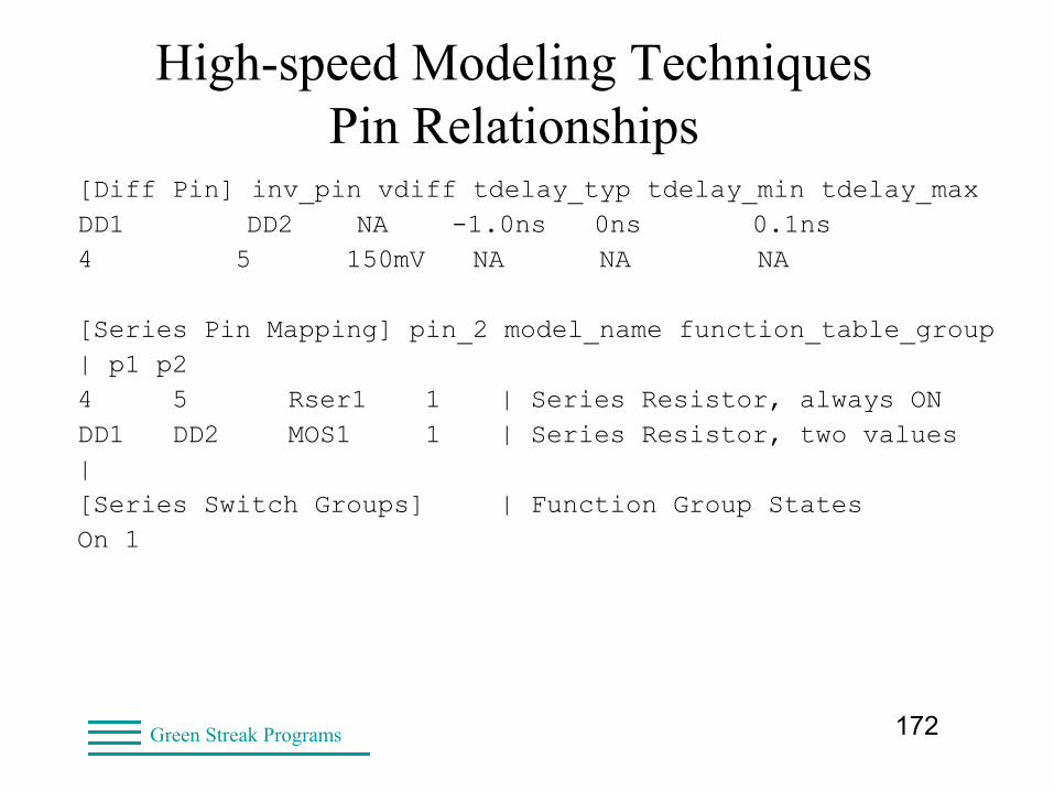
High-speed Modeling TechniquesPin Relationships
[Diff Pin] inv_pin vdiff tdelay_typ tdelay_min tdelay_maxDD1 DD2 NA -1.0ns 0ns 0.1ns4 5 150mV NA NA NA
[Series Pin Mapping] pin_2 model_name function_table_group| p1 p2 4 5 Rser1 1 | Series Resistor, always ONDD1 DD2 MOS1 1 | Series Resistor, two values|[Series Switch Groups] | Function Group StatesOn 1
173Green Streak Programs
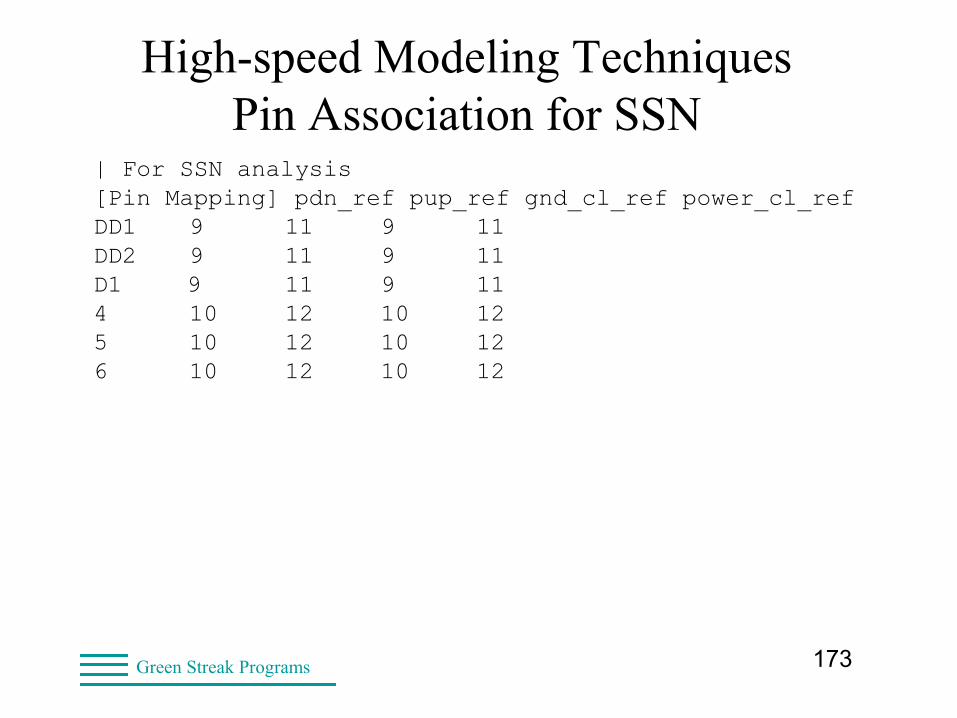
High-speed Modeling TechniquesPin Association for SSN
| For SSN analysis[Pin Mapping] pdn_ref pup_ref gnd_cl_ref power_cl_refDD1 9 11 9 11DD2 9 11 9 11D1 9 11 9 11 4 10 12 10 125 10 12 10 126 10 12 10 12
174Green Streak Programs
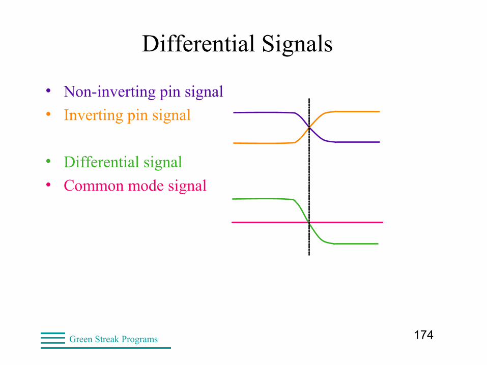
Differential Signals
• Non-inverting pin signal
• Inverting pin signal
• Differential signal
• Common mode signal
175Green Streak Programs
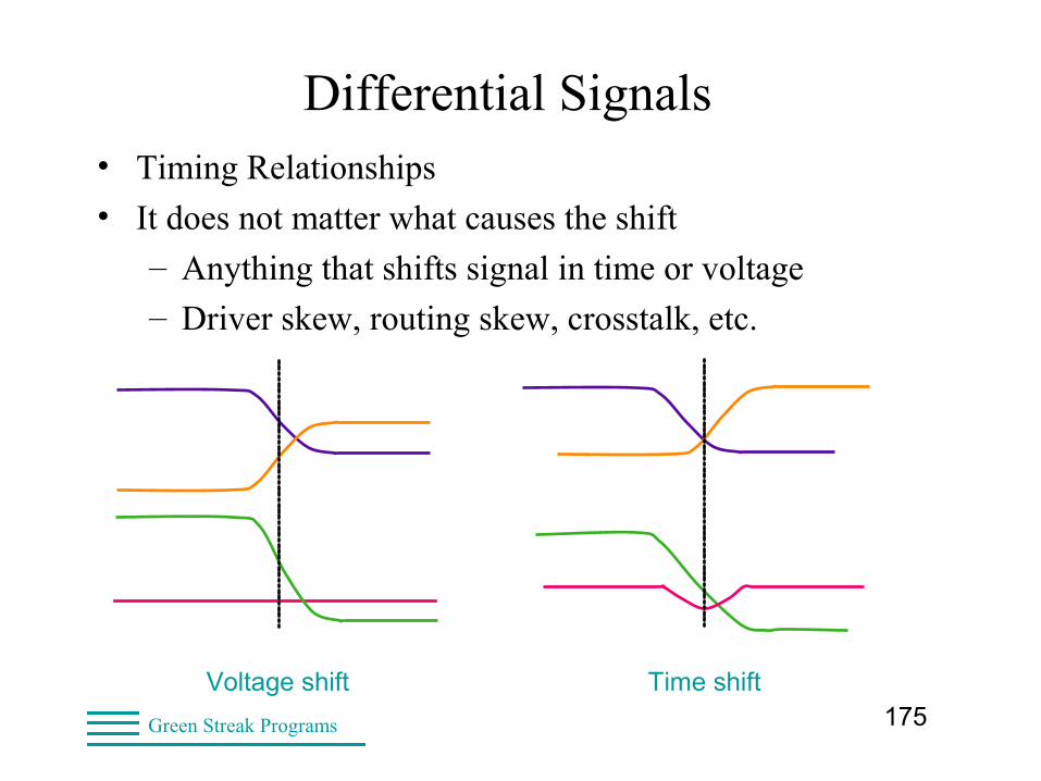
Differential Signals• Timing Relationships
• It does not matter what causes the shift
– Anything that shifts signal in time or voltage
– Driver skew, routing skew, crosstalk, etc.
Voltage shift Time shift
176Green Streak Programs
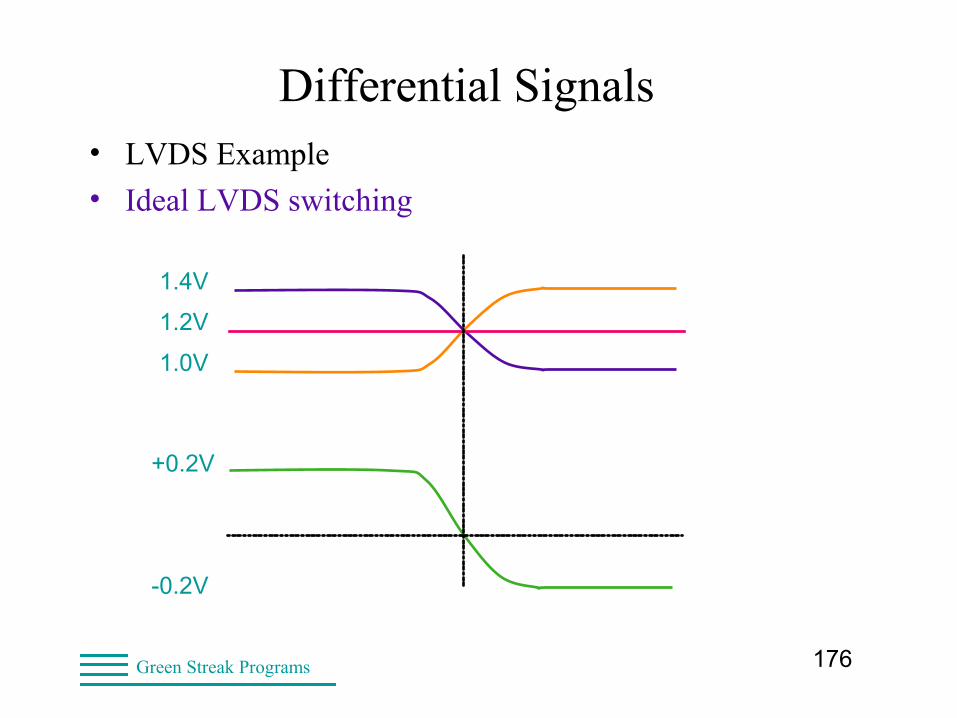
Differential Signals• LVDS Example
• Ideal LVDS switching
1.4V
1.2V
1.0V
+0.2V
-0.2V
177Green Streak Programs
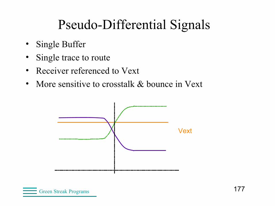
Pseudo-Differential Signals• Single Buffer
• Single trace to route
• Receiver referenced to Vext
• More sensitive to crosstalk & bounce in Vext
Vext
178Green Streak Programs
Paired-differential Signals• Inverting and non-inverting buffer pair
• Better than single-ended differential
– Reduces crosstalk sensitivity
• IBIS 3.2 assumed independent buffers
– Independent voltages and currents
– Slew rise/fall not required to match
• VHDL-AMS, Verilog-AMS, AMI
– Model true differential buffers together
179Green Streak Programs
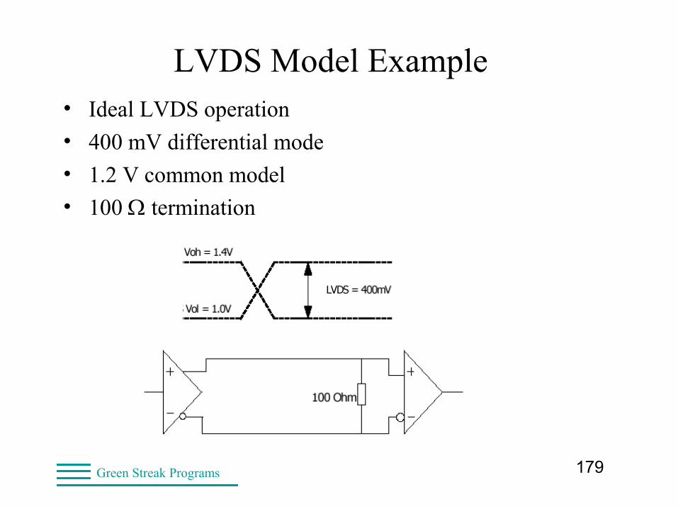
LVDS Model Example• Ideal LVDS operation
• 400 mV differential mode
• 1.2 V common model
• 100 termination
180Green Streak Programs
LVDS Model Example• LVDS IBIS Models @ 1.25GHz
– Douglas Burns, SiSoft
– Used for next two slides
– Intentional time offset in plots
• Capabilities and limitations of IBIS 3.2 models
IBIS Summit http://www.eda.org/pub/ibis/summits/jun02burns.zip: LVDS IBIS Models @ 1.25GHz (.ppt)burns.pdf: Douglas Burns, Steven Coe, andKevin Fisher, Signal Integrity Software (SiSoft)
181Green Streak Programs
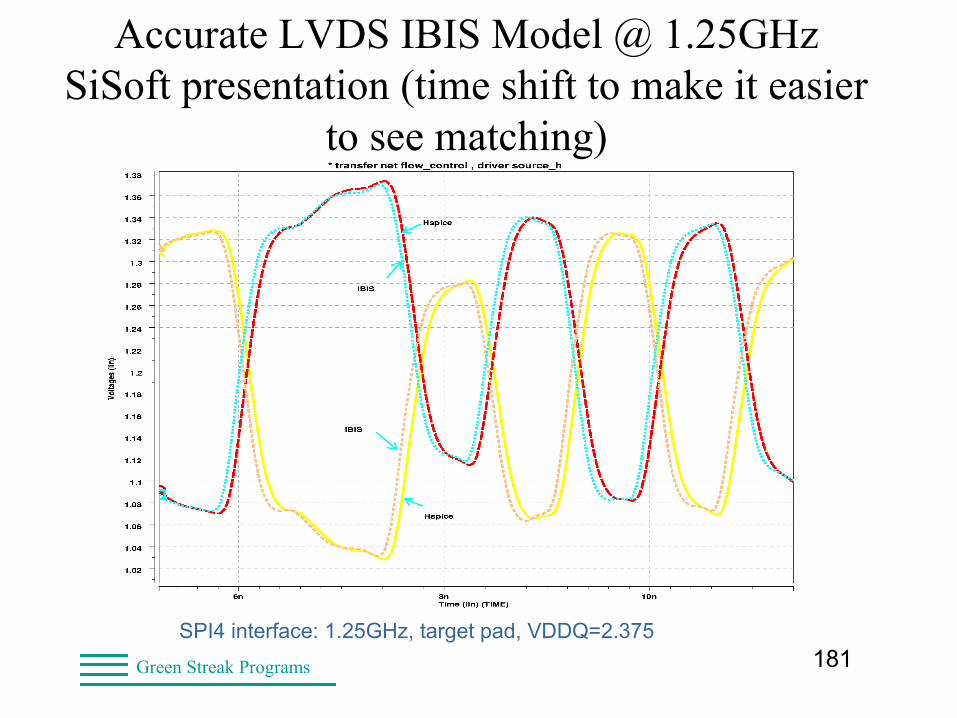
Accurate LVDS IBIS Model @ 1.25GHzSiSoft presentation (time shift to make it easier
to see matching)
SPI4 interface: 1.25GHz, target pad, VDDQ=2.375
182Green Streak Programs
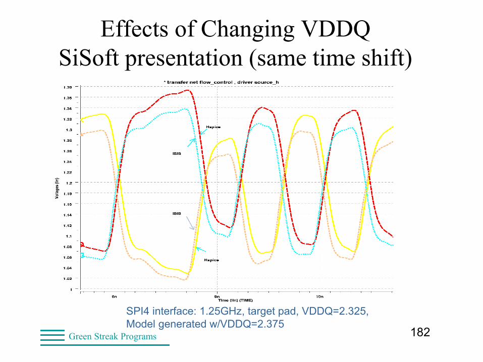
Effects of Changing VDDQSiSoft presentation (same time shift)
SPI4 interface: 1.25GHz, target pad, VDDQ=2.325,Model generated w/VDDQ=2.375

183Green Streak Programs
LVDS Model Example• Model made at one V_common
– Not valid if V_common changes
• Implications
– Hard to select Min, Max conditions
– Submodels for different V_common
• Reality is V_common changes with bit pattern
IBIS was never designed to handle this!
184Green Streak Programs
LVDS Model Example• IBIS 5.1 approach
– SPICE 3f5, VHDL-AMS, Verilog-AMS, AMI
• LVDS model in SPICE
– Requires both circuit and process data
– Multiple NDAs could be required
• LVDS model in AMS or AMI
– Behavioral equations
– Use of both digital and analog information
• Such as medium-term value of V_common
– Can include effects not addressed in IBIS 5.1
185Green Streak Programs
On-die Terminators• High-speed differential termination
• Inside the package and bond wire
• Minimizes reflection effects at the receiver
• Fixed or variable resistance
186Green Streak Programs
Representing On-die Terminators• Many ways to do this
• Use “terminator” model type
• Use [Series Current]
• Use [Series MOSFET]
• Include current in one of the clamp tables
• Include in a SubModel
– Termination can be disabled
– Value can be changed
187Green Streak Programs
Terminator in buffer method
• Do this within the [Model]
• To insert a resistor to GND
| variable R(typ) R(min) R(max)
[Rgnd] 100ohm 80ohm 120ohm
• To insert a series resistor| variable R(typ) R(min) R(max)
[R Series] 8ohm 6ohm 12ohm
188Green Streak Programs
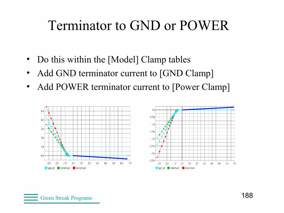
Terminator to GND or POWER
• Do this within the [Model] Clamp tables
• Add GND terminator current to [GND Clamp]
• Add POWER terminator current to [Power Clamp]
189Green Streak Programs
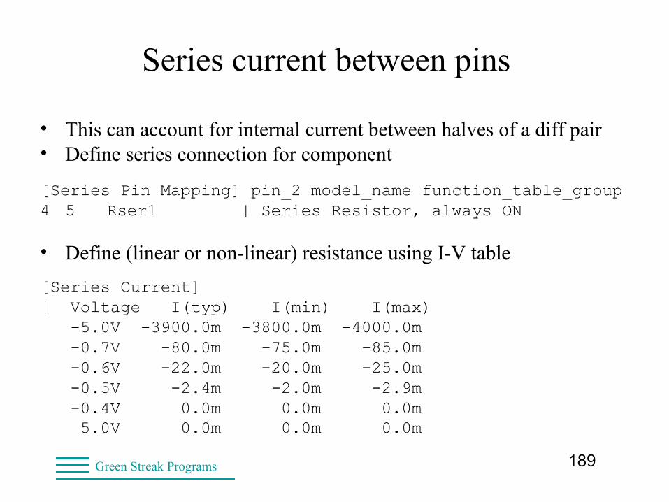
Series current between pins
• This can account for internal current between halves of a diff pair• Define series connection for component
[Series Pin Mapping] pin_2 model_name function_table_group 4 5 Rser1 | Series Resistor, always ON
• Define (linear or non-linear) resistance using I-V table
[Series Current]| Voltage I(typ) I(min) I(max) -5.0V -3900.0m -3800.0m -4000.0m -0.7V -80.0m -75.0m -85.0m -0.6V -22.0m -20.0m -25.0m -0.5V -2.4m -2.0m -2.9m -0.4V 0.0m 0.0m 0.0m 5.0V 0.0m 0.0m 0.0m
190Green Streak Programs
On-die Terminator Validation• Run ibischk5
• Check values visually
• Simulate
• Check results
191Green Streak Programs
High-Speed Interconnect Models• EDA tools connect PCB to package to component
using pin and trace connectivity
• EBD
• PKG
• [External Circuit] under construction
• ICM
• Touchstone
• IBIS-ISS (SPICE subset)
192Green Streak Programs
High-Speed Interconnect Models• EBD model
– Components on a module or daughter card
• PKG model
– One packaged IC
• ICM, Touchstone, IBIS-ISS
– Connect components across board
193Green Streak Programs
High-Speed Interconnect Models• EBD, PKG, [External Circuit]
– Check with ibischk5
• IBIS Interconnect (ICM)
– Check with icmchk1
• Touchstone
– Check with tschk2
• IBIS-ISS
– No SPICE parser specified
194Green Streak Programs
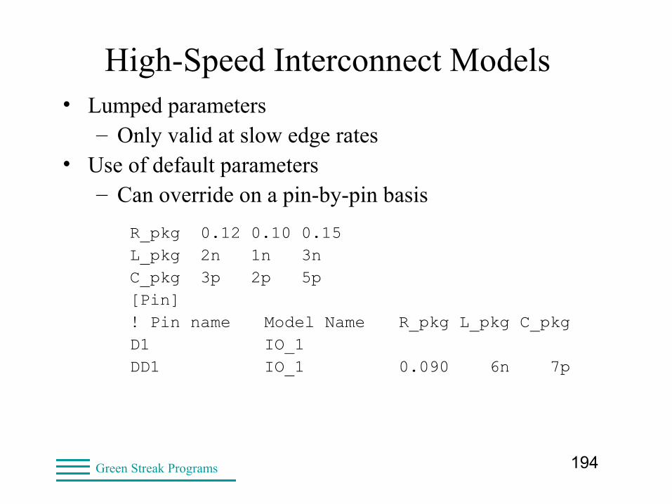
High-Speed Interconnect Models• Lumped parameters
– Only valid at slow edge rates• Use of default parameters
– Can override on a pin-by-pin basis
R_pkg 0.12 0.10 0.15L_pkg 2n 1n 3nC_pkg 3p 2p 5p[Pin]! Pin name Model Name R_pkg L_pkg C_pkgD1 IO_1DD1 IO_1 0.090 6n 7p
195Green Streak Programs
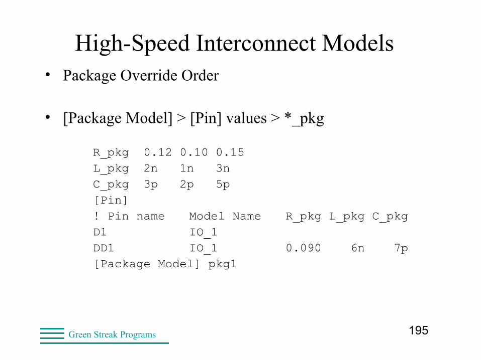
High-Speed Interconnect Models• Package Override Order
• [Package Model] > [Pin] values > *_pkg
R_pkg 0.12 0.10 0.15L_pkg 2n 1n 3nC_pkg 3p 2p 5p[Pin]! Pin name Model Name R_pkg L_pkg C_pkgD1 IO_1DD1 IO_1 0.090 6n 7p[Package Model] pkg1
196Green Streak Programs
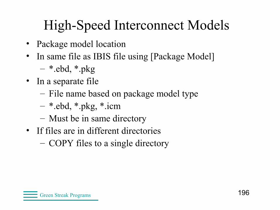
High-Speed Interconnect Models• Package model location• In same file as IBIS file using [Package Model]
– *.ebd, *.pkg• In a separate file
– File name based on package model type– *.ebd, *.pkg, *.icm– Must be in same directory
• If files are in different directories– COPY files to a single directory
197Green Streak Programs
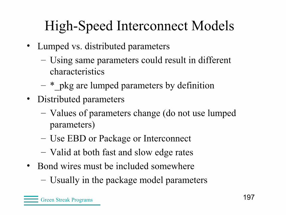
High-Speed Interconnect Models• Lumped vs. distributed parameters
– Using same parameters could result in different characteristics
– *_pkg are lumped parameters by definition
• Distributed parameters
– Values of parameters change (do not use lumped parameters)
– Use EBD or Package or Interconnect
– Valid at both fast and slow edge rates
• Bond wires must be included somewhere
– Usually in the package model parameters
198Green Streak Programs
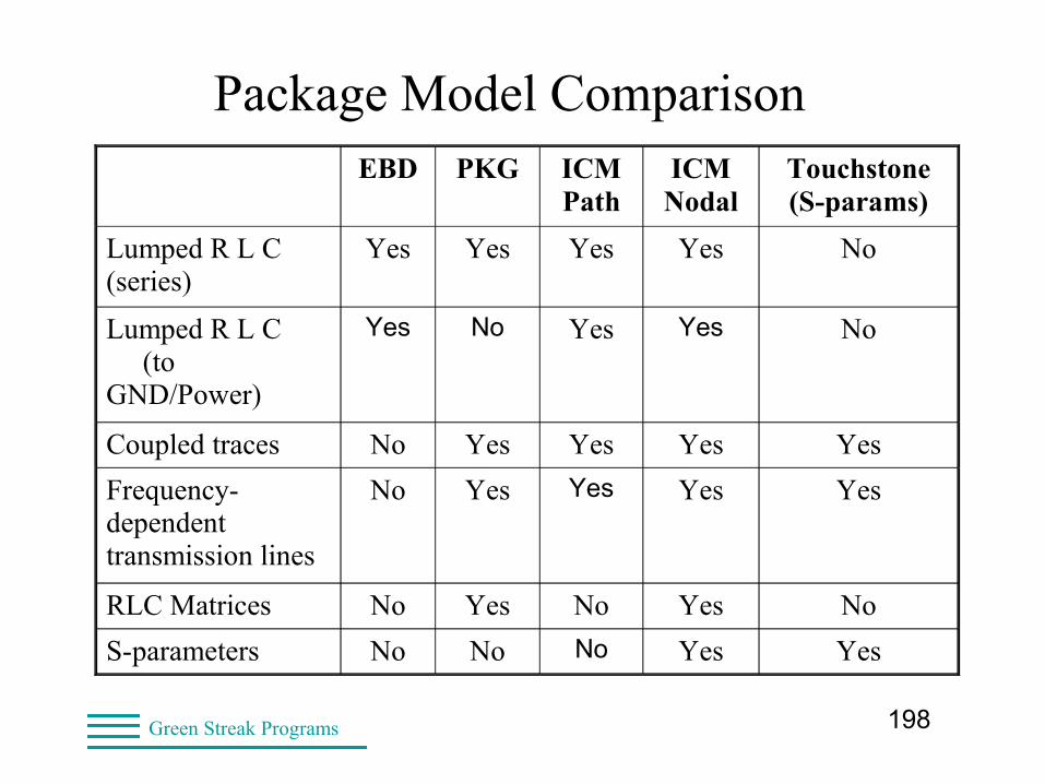
Package Model ComparisonEBD PKG ICM
PathICM Nodal
Touchstone (S-params)
Lumped R L C (series)
Yes Yes Yes Yes No
Lumped R L C (to GND/Power)
Yes No Yes Yes No
Coupled traces No Yes Yes Yes Yes
Frequency-dependent transmission lines
No Yes Yes Yes Yes
RLC Matrices No Yes No Yes No
S-parameters No No No Yes Yes
199Green Streak Programs
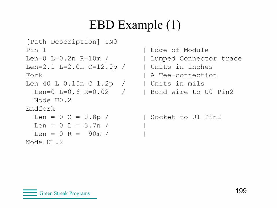
EBD Example (1)[Path Description] IN0Pin 1 | Edge of ModuleLen=0 L=0.2n R=10m / | Lumped Connector traceLen=2.1 L=2.0n C=12.0p / | Units in inchesFork | A Tee-connection Len=40 L=0.15n C=1.2p / | Units in mils Len=0 L=0.6 R=0.02 / | Bond wire to U0 Pin2 Node U0.2Endfork Len = 0 C = 0.8p / | Socket to U1 Pin2 Len = 0 L = 3.7n / | Len = 0 R = 90m / | Node U1.2
200Green Streak Programs
EBD Example (2)
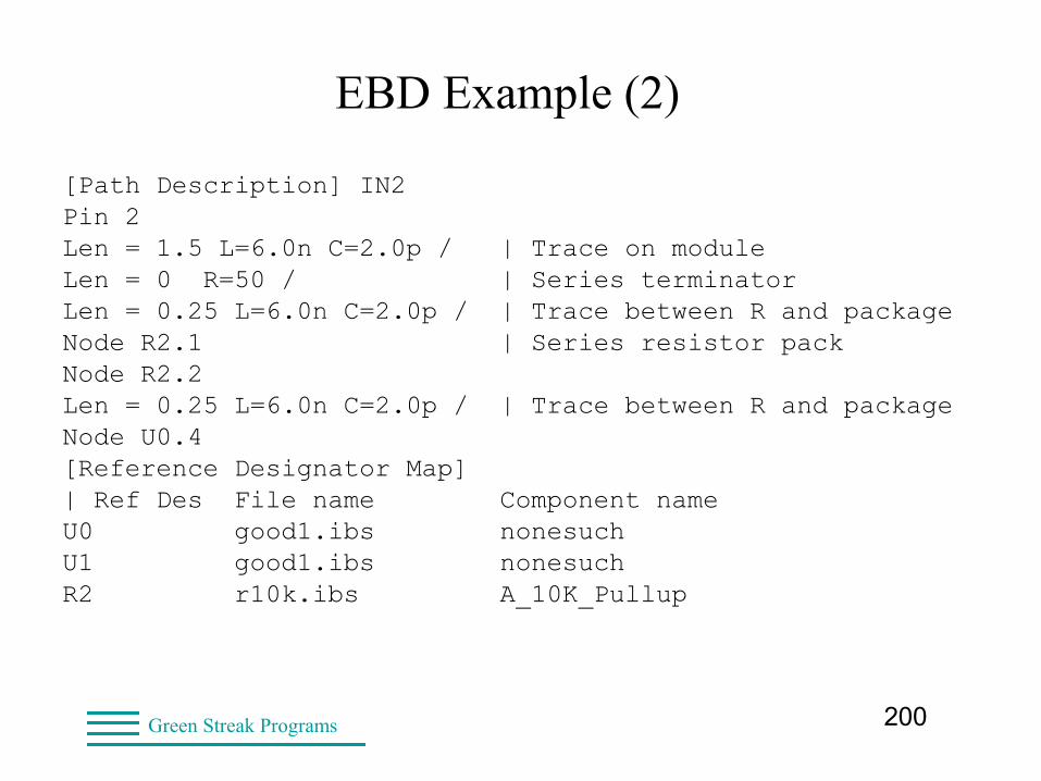
[Path Description] IN2Pin 2Len = 1.5 L=6.0n C=2.0p / | Trace on moduleLen = 0 R=50 / | Series terminatorLen = 0.25 L=6.0n C=2.0p / | Trace between R and packageNode R2.1 | Series resistor packNode R2.2Len = 0.25 L=6.0n C=2.0p / | Trace between R and packageNode U0.4[Reference Designator Map]| Ref Des File name Component nameU0 good1.ibs nonesuchU1 good1.ibs nonesuchR2 r10k.ibs A_10K_Pullup
201Green Streak Programs
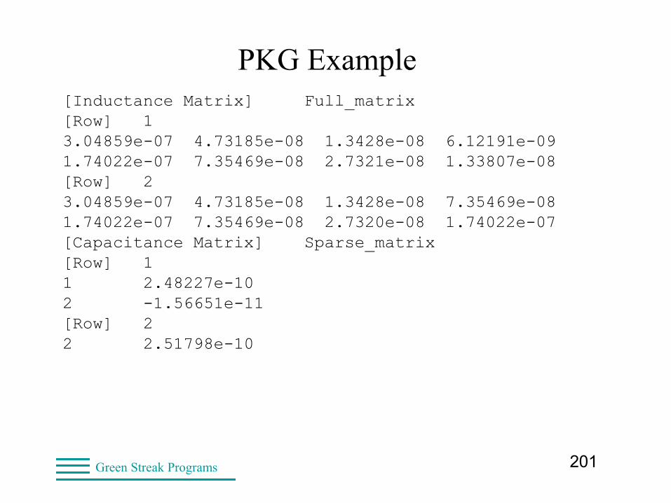
PKG Example[Inductance Matrix] Full_matrix[Row] 13.04859e-07 4.73185e-08 1.3428e-08 6.12191e-091.74022e-07 7.35469e-08 2.7321e-08 1.33807e-08[Row] 23.04859e-07 4.73185e-08 1.3428e-08 7.35469e-081.74022e-07 7.35469e-08 2.7320e-08 1.74022e-07[Capacitance Matrix] Sparse_matrix[Row] 11 2.48227e-102 -1.56651e-11[Row] 22 2.51798e-10
202Green Streak Programs
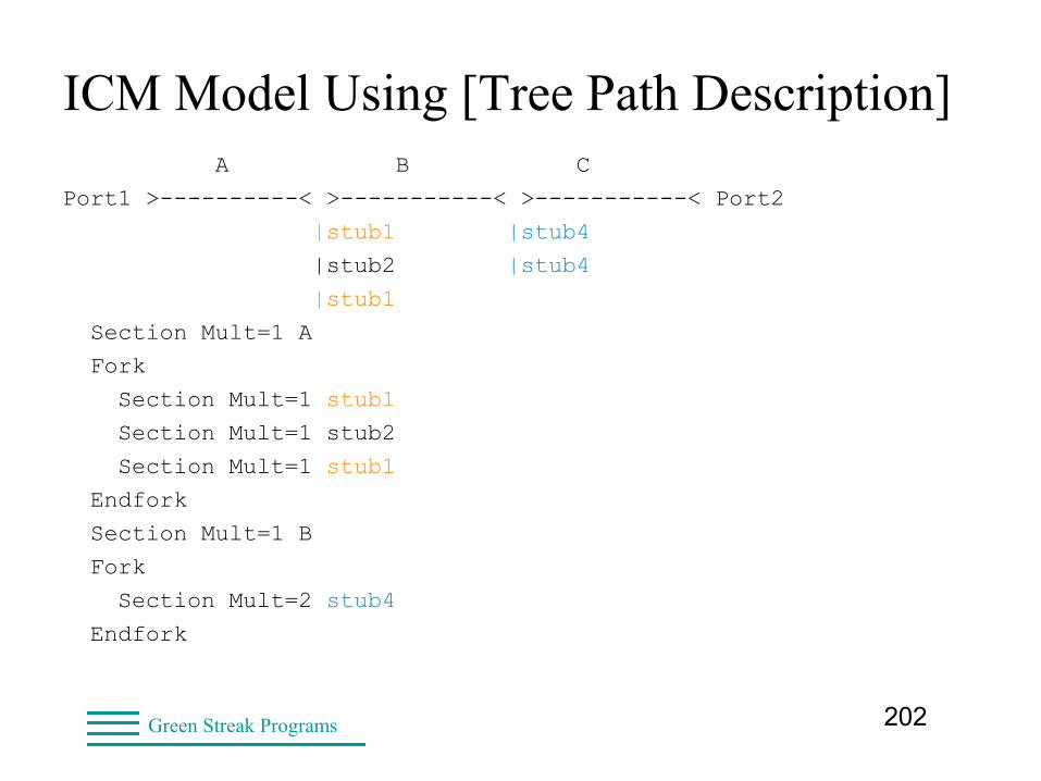
ICM Model Using [Tree Path Description] A B C
Port1 >----------< >-----------< >-----------< Port2
|stub1 |stub4
|stub2 |stub4
|stub1
Section Mult=1 A
Fork
Section Mult=1 stub1
Section Mult=1 stub2
Section Mult=1 stub1
Endfork
Section Mult=1 B
Fork
Section Mult=2 stub4
Endfork
203Green Streak Programs
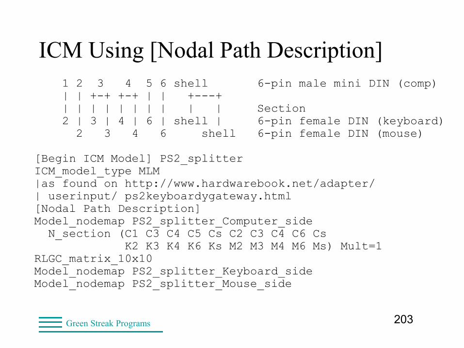
ICM Using [Nodal Path Description] 1 2 3 4 5 6 shell 6-pin male mini DIN (comp) | | +-+ +-+ | | +---+ | | | | | | | | | | Section 2 | 3 | 4 | 6 | shell | 6-pin female DIN (keyboard) 2 3 4 6 shell 6-pin female DIN (mouse)
[Begin ICM Model] PS2_splitterICM_model_type MLM|as found on http://www.hardwarebook.net/adapter/| userinput/ ps2keyboardygateway.html[Nodal Path Description]Model_nodemap PS2_splitter_Computer_side N_section (C1 C3 C4 C5 Cs C2 C3 C4 C6 Cs K2 K3 K4 K6 Ks M2 M3 M4 M6 Ms) Mult=1 RLGC_matrix_10x10Model_nodemap PS2_splitter_Keyboard_sideModel_nodemap PS2_splitter_Mouse_side
204Green Streak Programs
S-parameters in Components • PCB interconnects
• Termination models
• Packages
– For chips (I/O buffers)
– Passives (R, L, C, termination networks)
– Daughter cards
• Card slots (with or without components in them)
• Connectors
• Cables
205Green Streak Programs
Touchstone 2.0• No component or connection information
– Hides proprietary design
• Frequency characteristics
– Real and Imaginary
– Magnitude and Phase (degrees)
– dB or linear
– Limited freq. range
– Ideal = DC to daylight
– Sometimes need to add a near-DC point
– Enough bandwidth for edge rate
206Green Streak Programs
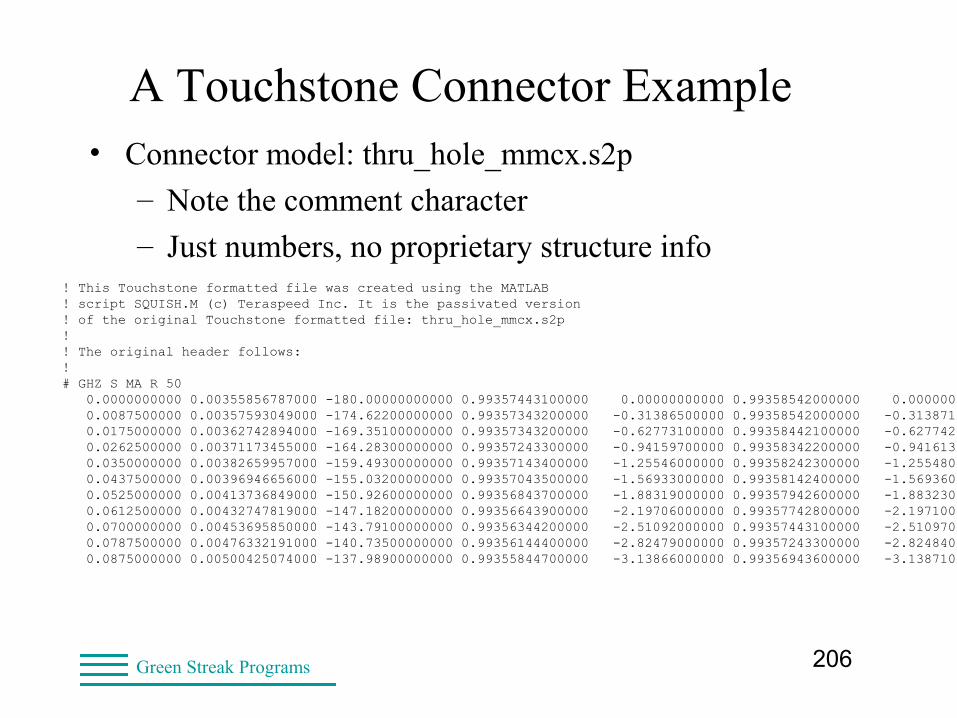
A Touchstone Connector Example • Connector model: thru_hole_mmcx.s2p
– Note the comment character
– Just numbers, no proprietary structure info! This Touchstone formatted file was created using the MATLAB! script SQUISH.M (c) Teraspeed Inc. It is the passivated version! of the original Touchstone formatted file: thru_hole_mmcx.s2p!! The original header follows:!# GHZ S MA R 50 0.0000000000 0.00355856787000 -180.00000000000 0.99357443100000 0.00000000000 0.99358542000000 0.00000000000 0.00351030618000 -180.00000000000 0.0087500000 0.00357593049000 -174.62200000000 0.99357343200000 -0.31386500000 0.99358542000000 -0.31387100000 0.00352807839000 -174.54600000000 0.0175000000 0.00362742894000 -169.35100000000 0.99357343200000 -0.62773100000 0.99358442100000 -0.62774200000 0.00358075566000 -169.20400000000 0.0262500000 0.00371173455000 -164.28300000000 0.99357243300000 -0.94159700000 0.99358342200000 -0.94161300000 0.00366694938000 -164.07700000000 0.0350000000 0.00382659957000 -159.49300000000 0.99357143400000 -1.25546000000 0.99358242300000 -1.25548000000 0.00378426195000 -159.24200000000 0.0437500000 0.00396946656000 -155.03200000000 0.99357043500000 -1.56933000000 0.99358142400000 -1.56936000000 0.00393002604000 -154.75100000000 0.0525000000 0.00413736849000 -150.92600000000 0.99356843700000 -1.88319000000 0.99357942600000 -1.88323000000 0.00410111478000 -150.63000000000 0.0612500000 0.00432747819000 -147.18200000000 0.99356643900000 -2.19706000000 0.99357742800000 -2.19710000000 0.00429460110000 -146.88400000000 0.0700000000 0.00453695850000 -143.79100000000 0.99356344200000 -2.51092000000 0.99357443100000 -2.51097000000 0.00450754794000 -143.50200000000 0.0787500000 0.00476332191000 -140.73500000000 0.99356144400000 -2.82479000000 0.99357243300000 -2.82484000000 0.00473739786000 -140.46500000000 0.0875000000 0.00500425074000 -137.98900000000 0.99355844700000 -3.13866000000 0.99356943600000 -3.13871000000 0.00498177324000 -137.74400000000
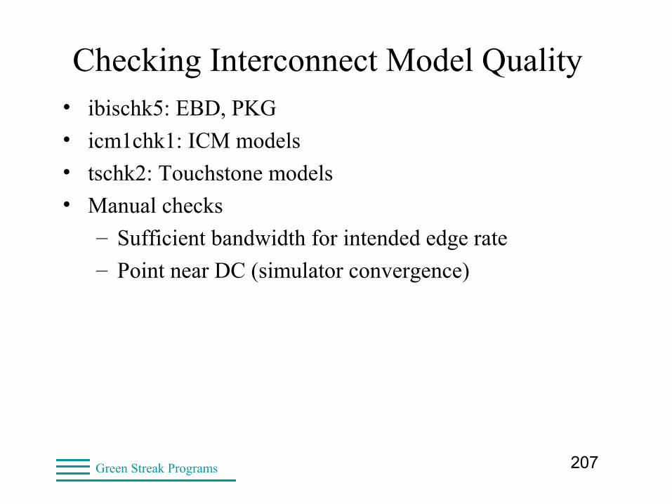
207Green Streak Programs
Checking Interconnect Model Quality• ibischk5: EBD, PKG
• icm1chk1: ICM models
• tschk2: Touchstone models
• Manual checks
– Sufficient bandwidth for intended edge rate
– Point near DC (simulator convergence)
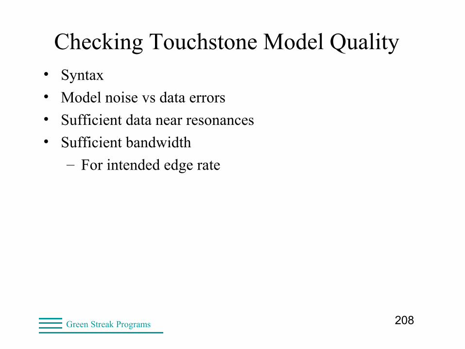
208Green Streak Programs
Checking Touchstone Model Quality• Syntax
• Model noise vs data errors
• Sufficient data near resonances
• Sufficient bandwidth
– For intended edge rate
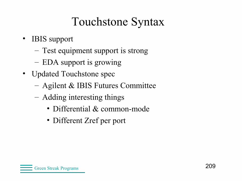
209Green Streak Programs
Touchstone Syntax• IBIS support
– Test equipment support is strong
– EDA support is growing
• Updated Touchstone spec
– Agilent & IBIS Futures Committee
– Adding interesting things
• Differential & common-mode
• Different Zref per port
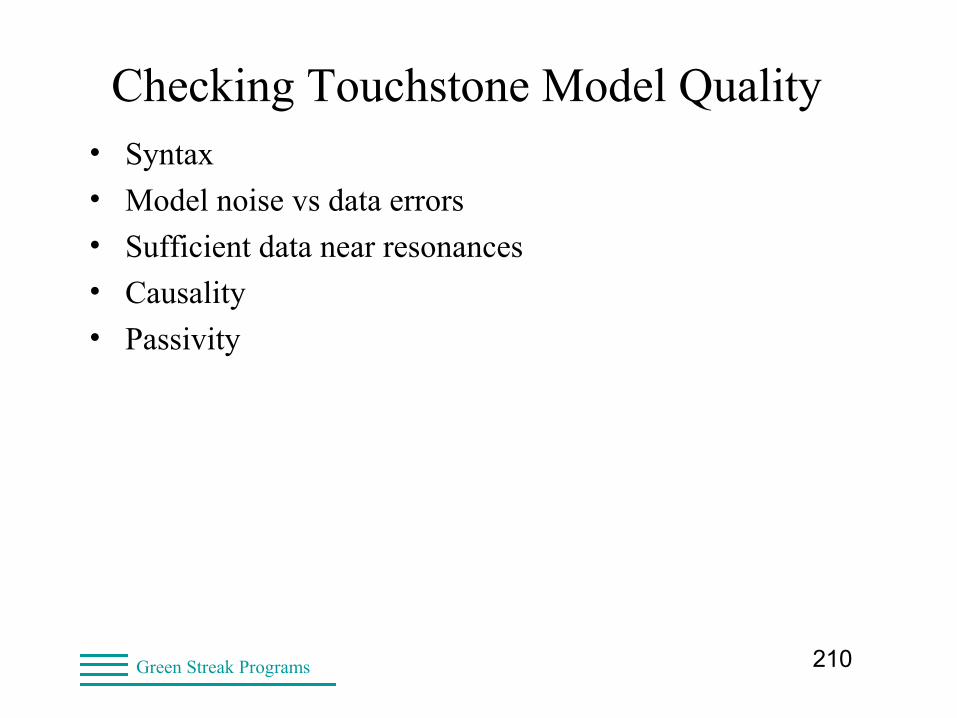
210Green Streak Programs
Checking Touchstone Model Quality• Syntax
• Model noise vs data errors
• Sufficient data near resonances
• Causality
• Passivity
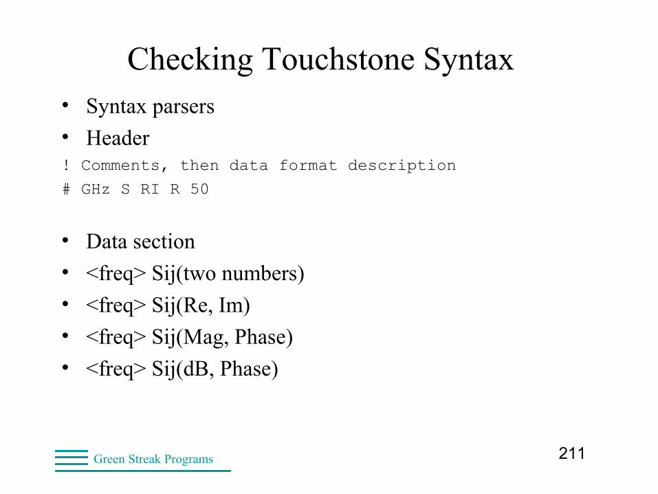
211Green Streak Programs
Checking Touchstone Syntax• Syntax parsers
• Header! Comments, then data format description
# GHz S RI R 50
• Data section
• <freq> Sij(two numbers)
• <freq> Sij(Re, Im)
• <freq> Sij(Mag, Phase)
• <freq> Sij(dB, Phase)
212Green Streak Programs
Checking Touchstone Data• Frequency points
– 0 ≤ Mag ≤ 1 (-∞ to 0 dB)
– Phase in degrees (usually -180 to +180)
• At DC, phase = 0 or ±180 (Im = 0)
• At f=∞, phase = 0 or ±180 (Im = 0)
• Polar chart – data moves only clockwise
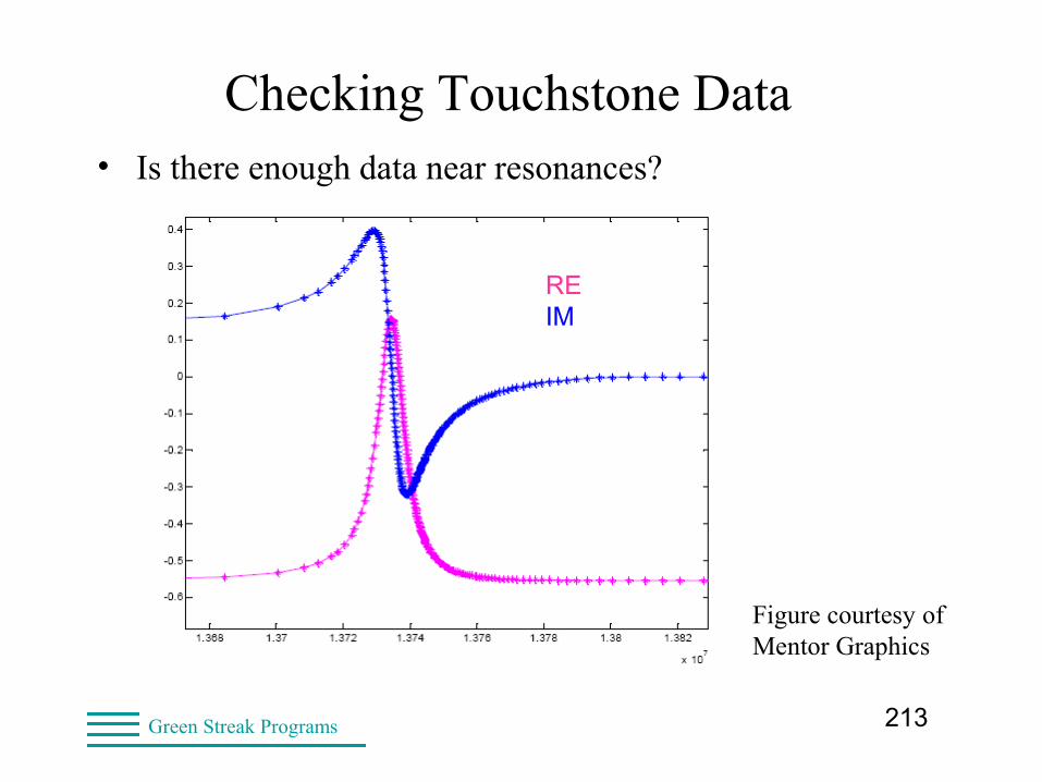
213Green Streak Programs
Checking Touchstone Data• Is there enough data near resonances?
Figure courtesy of Mentor Graphics
RE IM
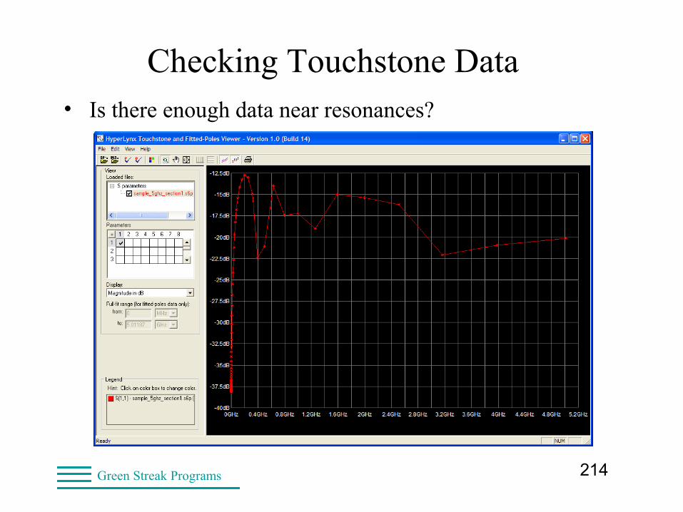
214Green Streak Programs
Checking Touchstone Data• Is there enough data near resonances?
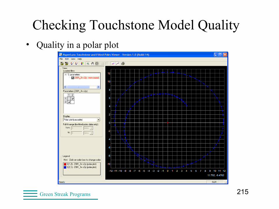
215Green Streak Programs
Checking Touchstone Model Quality• Quality in a polar plot
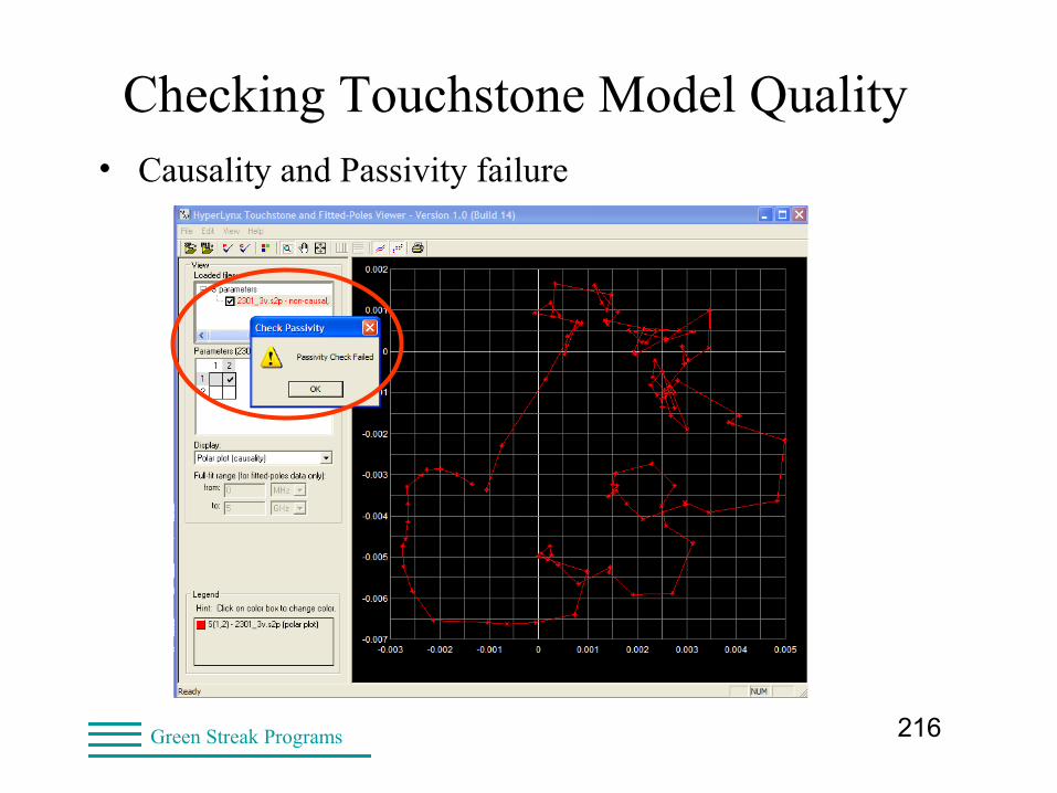
216Green Streak Programs
Checking Touchstone Model Quality• Causality and Passivity failure
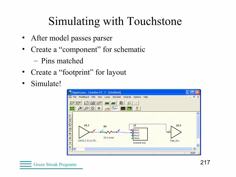
217Green Streak Programs
Simulating with Touchstone• After model passes parser
• Create a “component” for schematic
– Pins matched
• Create a “footprint” for layout
• Simulate!
218Green Streak Programs
SPICE, VHDL-AMS, AMI• IBIS 4.2 and 5.1 support external models
• SPICE 3f5 compatible
• VHDL-AMS and Verilog-AMS compatible
• AMI: algorithmic (coded) models
• Might require tool/license to test
219Green Streak Programs
SPICE, VHDL-AMS, AMI• Sometimes the IBIS model is simply not adequate
– Examples: LVDS, pre-emphasis
• VHDL-AMS and Verilog-AMS supported
– I/O buffer models
– Interconnect models
• AMI (coded models)
– Compiled, but sometimes not tested
– No parser
– Test by simulating and checking results
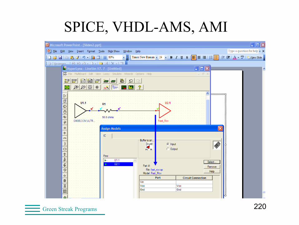
220Green Streak Programs
SPICE, VHDL-AMS, AMI
221Green Streak Programs
SPICE, VHDL-AMS, AMI Model Quality• Syntax – caught at simulation time
• Pin assignment on EBD, PKG, connectors, etc.
– Signal path (IC – R – L – C – Tline – IC)
– Touchstone: no maker control of pin order
– Backplanes & daughter cards
• Validating model with simulation results
– For the I/O buffer and a resistive load
– For the component in a “known good” design
222Green Streak Programs
Validation in Your Flow
• Check each component
• Check each model (IBIS, Touchstone, SPICE, etc.)
• About 5 minutes for simple models
– Longer for complex models
• Run IBIS Quality checklist
• Getting the most bang for your buck
– Compare prototype with simulation
223Green Streak Programs
Summary• Things we have covered
• Comparing SPICE and IBIS
• I/O model validation
• Differential models
• Package and interconnect models
• IBIS with SPICE, VHDL-AMS, Verilog-AMS, AMI
224Green Streak Programs
Summary• Not all features are supported by all vendors
– Parser updates take months
– Support is limited for some featuresof IBIS 5.1, ICM, Touchstone
– Check with your EDA vendor
• Critical features are better supported
– Such as S-parameters
• IBIS Model Review Committee
– Accepts models from model makers
– Can check all IBIS files (Touchstone, AMI, etc.)
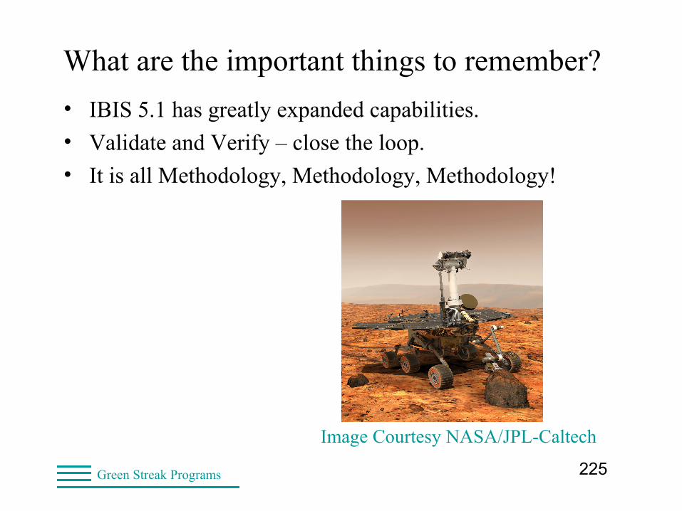
225Green Streak Programs
What are the important things to remember?
• IBIS 5.1 has greatly expanded capabilities.
• Validate and Verify – close the loop.
• It is all Methodology, Methodology, Methodology!
Image Courtesy NASA/JPL-Caltech
226Green Streak Programs
IBIS Web Sites
• Home Page http://www.eda.org/ibis/
• IBIS Summit papers http://www.eda.org/ibis/articles.htm
Also Training Materials (including Arpad’s)
• Quality Checklist http://www.eda.org/ibis/quality_wip/checklist.html
227Green Streak Programs
Email Reflectors
• Send email with “subscribe” in the subject line
• ibis-users and ibis
• SI-list
Technical documents at http://www.si-list.net