IAEA-TECDOC-1785 IAEA TECDOC SERIES · synergetic energy systems that combine nuclear and renewable...
154
Design Safety Considerations for Water Cooled Small Modular Reactors Incorporating Lessons Learned from the Fukushima Daiichi Accident @ IAEA-TECDOC-1785 IAEA-TECDOC-1785 IAEA TECDOC SERIES
Transcript of IAEA-TECDOC-1785 IAEA TECDOC SERIES · synergetic energy systems that combine nuclear and renewable...
Design Safety Considerations for Water Cooled Sm
all Modular Reactors Incorporating Lessons Learned from
the Fukushima Daiichi Accident
IAEA-TECDOC-1785
Design Safety Considerations for Water Cooled Small Modular Reactors Incorporating Lessons Learned from the Fukushima Daiichi Accident
@
IAEA-TECDOC-1785
IAEA-TECDOC-1785
IAEA TECDOC SERIES

DESIGN SAFETY CONSIDERATIONS FOR WATER COOLED SMALL MODULAR
REACTORS INCORPORATING LESSONS LEARNED FROM THE
FUKUSHIMA DAIICHI ACCIDENT

AFGHANISTANALBANIAALGERIAANGOLAANTIGUA AND BARBUDAARGENTINAARMENIAAUSTRALIAAUSTRIAAZERBAIJANBAHAMASBAHRAINBANGLADESHBARBADOSBELARUSBELGIUMBELIZEBENINBOLIVIA, PLURINATIONAL
STATE OFBOSNIA AND HERZEGOVINABOTSWANABRAZILBRUNEI DARUSSALAMBULGARIABURKINA FASOBURUNDICAMBODIACAMEROONCANADACENTRAL AFRICAN
REPUBLICCHADCHILECHINACOLOMBIACONGOCOSTA RICACÔTE D’IVOIRECROATIACUBACYPRUSCZECH REPUBLICDEMOCRATIC REPUBLIC
OF THE CONGODENMARKDJIBOUTIDOMINICADOMINICAN REPUBLICECUADOREGYPTEL SALVADORERITREAESTONIAETHIOPIAFIJIFINLANDFRANCEGABON
GEORGIAGERMANYGHANAGREECEGUATEMALAGUYANAHAITIHOLY SEEHONDURASHUNGARYICELANDINDIAINDONESIAIRAN, ISLAMIC REPUBLIC OF IRAQIRELANDISRAELITALYJAMAICAJAPANJORDANKAZAKHSTANKENYAKOREA, REPUBLIC OFKUWAITKYRGYZSTANLAO PEOPLE’S DEMOCRATIC
REPUBLICLATVIALEBANONLESOTHOLIBERIALIBYALIECHTENSTEINLITHUANIALUXEMBOURGMADAGASCARMALAWIMALAYSIAMALIMALTAMARSHALL ISLANDSMAURITANIAMAURITIUSMEXICOMONACOMONGOLIAMONTENEGROMOROCCOMOZAMBIQUEMYANMARNAMIBIANEPALNETHERLANDSNEW ZEALANDNICARAGUANIGERNIGERIANORWAY
OMANPAKISTANPALAUPANAMAPAPUA NEW GUINEAPARAGUAYPERUPHILIPPINESPOLANDPORTUGALQATARREPUBLIC OF MOLDOVAROMANIARUSSIAN FEDERATIONRWANDASAN MARINOSAUDI ARABIASENEGALSERBIASEYCHELLESSIERRA LEONESINGAPORESLOVAKIASLOVENIASOUTH AFRICASPAINSRI LANKASUDANSWAZILANDSWEDENSWITZERLANDSYRIAN ARAB REPUBLICTAJIKISTANTHAILANDTHE FORMER YUGOSLAV
REPUBLIC OF MACEDONIATOGOTRINIDAD AND TOBAGOTUNISIATURKEYUGANDAUKRAINEUNITED ARAB EMIRATESUNITED KINGDOM OF
GREAT BRITAIN AND NORTHERN IRELAND
UNITED REPUBLICOF TANZANIA
UNITED STATES OF AMERICAURUGUAYUZBEKISTANVANUATUVENEZUELA, BOLIVARIAN
REPUBLIC OF VIET NAMYEMENZAMBIAZIMBABWE
The following States are Members of the International Atomic Energy Agency:
The Agency’s Statute was approved on 23 October 1956 by the Conference on the Statute of the IAEA held at United Nations Headquarters, New York; it entered into force on 29 July 1957. The Headquarters of the Agency are situated in Vienna. Its principal objective is “to accelerate and enlarge the contribution of atomic energy to peace, health and prosperity throughout the world’’.
IAEA-TECDOC-1785
DESIGN SAFETY CONSIDERATIONS FOR WATER COOLED SMALL MODULAR
REACTORS INCORPORATING LESSONS LEARNED FROM THE
FUKUSHIMA DAIICHI ACCIDENT
INTERNATIONAL ATOMIC ENERGY AGENCYVIENNA, 2016
COPYRIGHT NOTICE
All IAEA scientific and technical publications are protected by the terms of the Universal Copyright Convention as adopted in 1952 (Berne) and as revised in 1972 (Paris). The copyright has since been extended by the World Intellectual Property Organization (Geneva) to include electronic and virtual intellectual property. Permission to use whole or parts of texts contained in IAEA publications in printed or electronic form must be obtained and is usually subject to royalty agreements. Proposals for non-commercial reproductions and translations are welcomed and considered on a case-by-case basis. Enquiries should be addressed to the IAEA Publishing Section at:
Marketing and Sales Unit, Publishing SectionInternational Atomic Energy AgencyVienna International CentrePO Box 1001400 Vienna, Austriafax: +43 1 2600 29302tel.: +43 1 2600 22417email: [email protected] http://www.iaea.org/books
For further information on this publication, please contact:
Nuclear Power Technology Development SectionInternational Atomic Energy Agency
Vienna International CentrePO Box 100
1400 Vienna, AustriaEmail: [email protected]
© IAEA, 2016Printed by the IAEA in Austria
March 2016
IAEA Library Cataloguing in Publication Data
Names: International Atomic Energy Agency.Title: Design safety considerations for water cooled small modular reactors incorporating lessons learned from the Fukushima Daiichi accident / International Atomic Energy Agency.Description: Vienna : International Atomic Energy Agency, 2016. | Series: IAEA TECDOC series, ISSN 1011–4289 ; no. 1785 | Includes bibliographical references.Identifiers: IAEAL 16-01027 | ISBN 978–92–0–100716–2 (paperback : alk. paper) Subjects: LCSH: Nuclear reactors — Safety measures. | Nuclear power plants — Accidents — Prevention. | Nuclear reactors — Design and construction. | Water cooled reactors.
FOREWORD The global future deployment of advanced nuclear reactors for electricity generation depends primarily on the ability of nuclear industries, utilities and regulatory authorities to further enhance their reliability and economic competitiveness while satisfying stringent safety requirements. The IAEA has a project to help coordinate Member State efforts in the development and deployment of small and medium sized or small modular reactor (SMR) technology. This project aims simultaneously to facilitate SMR technology developers and potential SMR users, particularly States embarking on a nuclear power programme, in identifying key enabling technologies and enhancing capacity building by resolving issues relevant to deployment, including nuclear reactor safety. The objective of this publication is to explore common practices for Member States, which will be an essential resource for future development and deployment of SMR technology. The accident at the Fukushima Daiichi nuclear power plant was caused by an unprecedented combination of natural events: a strong earthquake, beyond the design basis, followed by a series of tsunamis of heights exceeding the design basis tsunami considered in the flood analysis for the site. Consequently, all the operating nuclear power plants and advanced reactors under development, including SMRs, have been incorporating lessons learned from the accident to assure and enhance the performance of the engineered safety features in coping with such external events. In response to the Fukushima Daiichi accident, the IAEA established an Action Plan on Nuclear Safety. The preparation of this publication was carried out within the framework of the IAEA Action Plan on effectively utilizing research and development. The main objective of this publication is to present technology developers and users with common considerations, approaches and measures for enhancing the defence in depth and operability of water cooled SMR design concepts to cope with extreme natural hazards. Indicative requirements to prevent such an accident from recurring are also provided for States planning to adopt water cooled SMR designs and technologies. The IAEA gratefully acknowledges the information on technology and safety aspects provided by SMR design organizations and information regarding technical requirements provided by several Member States. The IAEA officers responsible for this publication were M.H. Subki of the Division of Nuclear Power and M. Kim of the Division of Nuclear Installation Safety.
EDITORIAL NOTE
This publication has been prepared from the original material as submitted by the contributors and has not been edited by the editorial staff of the IAEA. The views expressed remain the responsibility of the contributors and do not necessarily represent the views of the IAEA or its Member States.
Neither the IAEA nor its Member States assume any responsibility for consequences which may arise from the use of this publication. This publication does not address questions of responsibility, legal or otherwise, for acts or omissions on the part of any person.
The use of particular designations of countries or territories does not imply any judgement by the publisher, the IAEA, as to the legal status of such countries or territories, of their authorities and institutions or of the delimitation of their boundaries.
The mention of names of specific companies or products (whether or not indicated as registered) does not imply any intention to infringe proprietary rights, nor should it be construed as an endorsement or recommendation on the part of the IAEA.
The IAEA has no responsibility for the persistence or accuracy of URLs for external or third party Internet web sites referred to in this publication and does not guarantee that any content on such web sites is, or will remain, accurate or appropriate.

CONTENTS
1. INTRODUCTION .................................................................................................... 1
BACKGROUND ............................................................................................. 1 1.1.
OBJECTIVES .................................................................................................. 3 1.2.
SCOPE ............................................................................................................ 3 1.3.
APPROACH TO THE PREPARATION OF THIS PUBLICATION ................ 4 1.4.
2. OVERVIEW OF THE FUKUSHIMA DAIICHI ACCIDENT ................................... 6
3. REVIEW OF ENGINEERED SAFETY FEATURE DESIGN OF SMALL
MODULAR REACTORS AND ADVANCED REACTORS .................................. 13
TRIP AND SAFETY SHUTDOWN SYSTEMS ............................................ 13 3.1.
RESIDUAL HEAT REMOVAL SYSTEM .................................................... 13 3.2.
Residual heat removal through steam generator and heat exchanger 3.2.1.
submerged in water pool ................................................................... 13
Residual heat removal using passively cooled condenser ................... 14 3.2.2.
Residual heat removal using pump and heat exchanger ..................... 14 3.2.3.
SAFETY INJECTION SYSTEM ................................................................... 15 3.3.
High pressure injection system .......................................................... 15 3.3.1.
Low pressure injection system ........................................................... 17 3.3.2.
CONTAINMENT SYSTEM (CONFINEMENT OF RADIOACTIVE 3.4.
MATERIAL) ................................................................................................. 19
Pressure suppression containment ..................................................... 19 3.4.1.
Concrete containment with spray system ........................................... 20 3.4.2.
Submerged metal containment .......................................................... 20 3.4.3.
Passively cooled large volume metal containment ............................. 21 3.4.4.
SEVERE ACCIDENT MITIGATION FEATURES ....................................... 21 3.5.
In-vessel retention system ................................................................. 21 3.5.1.
Core catcher ...................................................................................... 22 3.5.2.
Hydrogen control devices .................................................................. 23 3.5.3.
Filtered containment venting system ................................................. 24 3.5.4.
DEFENCE IN DEPTH IN SMALL MODULAR REACTORS ...................... 24 3.6.
4. COUNTERMEASURES TO ADDRESS THE LESSONS LEARNED FROM THE
FUKUSHIMA DAIICHI ACCIDENT IN THE DESIGN OF WATER COOLED
SMALL MODULAR REACTORS ......................................................................... 34
DESIGN AND SITING ................................................................................. 36 4.1.
Strengthen measures against extreme natural hazards and 4.1.1.
consequential effects ........................................................................ 36
Consider issues concerning multiple-unit sites................................... 40 4.1.2.
Enhance off-site and on-site electricity supplies ................................ 42 4.1.3.
Ensure robust measures for reactor core cooling and ultimate heat 4.1.4.
sinks ................................................................................................. 46
Enhance design of safety-related structures, systems and 4.1.5.
components ...................................................................................... 48
Ensure measures for prevention and mitigation of hydrogen 4.1.6.
explosions ........................................................................................ 52
Enhance containment venting and filtering system ............................ 54 4.1.7.
Ensure hardened instrumentation and cables for safety-related 4.1.8.
parameters and monitoring equipment .............................................. 56
Enhanced robustness of spent fuel cooling ........................................ 58 4.1.9.
Use of effective probabilistic safety assessment for risk assessment 4.1.10.
and management ............................................................................... 61
ON-SITE EMERGENCY PREPAREDNESS AND RESPONSE ................... 63 4.2.
Ensure on-site emergency response facilities, equipment and 4.2.1.
procedures ........................................................................................ 63
Enhance human resource, skill and capabilities ................................. 67 4.2.2.
OFF-SITE EMERGENCY PREPAREDNESS AND RESPONSE ................. 68 4.3.
Strengthen off-site infrastructure and capability ................................ 68 4.3.1.
Strengthen national arrangements for emergency preparedness and 4.3.2.
response ........................................................................................... 69
Enhance interaction and communication with the international 4.3.3.
communities ..................................................................................... 70
NUCLEAR SAFETY INFRASTRUCTURES................................................ 71 4.4.
Review and clarify regulatory and emergency response framework ... 71 4.4.1.
Reinforce safety regulatory bodies and legal structures...................... 72 4.4.2.
Instil safety awareness and attitude .................................................... 73 4.4.3.
5. CONCLUDING REMARKS .................................................................................. 74
REFERENCES ................................................................................................................ 79
DEFINITIONS OF TERMS ............................................................................................. 83
ABBREVIATIONS ......................................................................................................... 87
ANNEX I......................................................................................................................... 91
ANNEX II ..................................................................................................................... 110
1
1. INTRODUCTION
BACKGROUND 1.1.
In the past few years, the Agency saw a substantial increase in the participation of Member
States in its programme for the development of small and medium-sized or modular
reactors (SMRs) technology. The current driving efforts in the development of such
reactors include: fulfilling the need for flexible power generation for a wider range of users
and applications; replacing the ageing fossil fuel-fired power plants; enhancing safety
performance through inherent and passive safety features; offering better economic
affordability; suitability for non-electric applications; options for remote areas; and
synergetic energy systems that combine nuclear and renewable energy sources. For the
context of this report, SMRs stand for small modular reactors and are defined in general as
advanced nuclear reactors that produce equivalent electric power of up to 300 MW(e) and
are designed to be built in factories and transportable to utilities for installation as demand
arises. In this report, the focus is on water cooled SMR designs that are under
development. Some of the designs are to be deployed as multi-module power plants. For
water cooled SMRs, modularity is achieved by integrating major components of the reactor
coolant system inside the reactor pressure vessel – in the same compartment with the
reactor core and internals. Several countries are also pioneering in the development of
transportable nuclear power plant (TNPP), including floating and marine-based SMRs.
To date, three reactors in the SMR category are under construction, i.e. in Argentina
(CAREM25, an industrial prototype integral PWR), in the Russian Federation (KLT-40S, a
barge mounted floating power unit) and in China (HTR-PM, an industrial demonstration
plant of high temperature pebble bed gas cooled reactor). Dozens of advanced SMR
designs are under development for near term deployment including in the United States of
America (B&W mPower and NuScale’s SMR design, both received government funding
for design certification, as well as the Westinghouse SMR and the SMR-160). The System-
integrated Modular Advanced ReacTor (SMART) from the Republic of Korea and
CAREM25 from Argentina are the water cooled SMR designs that have obtained design
approval from the respective governments. China has been developing the ACP100 design
for potential near term deployment.
The accident at the Fukushima Daiichi nuclear power plant (NPP) on 11 March 2011 in
Japan reveals the need for the nuclear community to prepare for unexpected circumstances
that go beyond the design basis events. No matter how well plants are operated and
maintained, there is always the potential for unexpected and high consequence situations.
The Fukushima Daiichi accident imparted many valuable lessons on both technical and
economic impacts in utilizing nuclear energy. The accident has disclosed various existing
design weaknesses and vulnerabilities, especially when combination of unprecedented
natural phenomena occurs. Actions taken by the operators and the emergency response
team during the early phase of the accident showed that the weaknesses were not only in
the hardware and the design of the reactor but also due to limitations of the human
capability, accident management and emergency operating procedures, emergency
infrastructures and regulatory framework.
Realizing that other unprecedented site/region-specific events could disrupt reactor
operation in the same scale or more than what happened in the Fukushima Daiichi
accident, not necessarily a large tsunami, nuclear community needs to take lessons from
the accident and transform them into appropriate design enhancements, actions, and other
2
countermeasures in water cooled reactors, both those in operations and near term
deployable designs.
The engineered safety features (ESFs) of the Fukushima Daiichi NPP were not damaged
by the earthquake but the water and debris of the tsunamis crippled and disabled them. The
disability of the ESF resulted in extensive damage to the nuclear power plant and released
radioactivity to the environment. The accident prompted the nuclear industry to revisit the
safety principles with further strengthening and additional assumptions that ESFs,
otherwise considered robust and failsafe, are in fact vulnerable in some natural events or
their never before assumed combination.
Based on the current trend, more attention should be given to water cooled SMR designs as
this type of reactor is being considered as options to fulfill future energy demands due to
their technological features to suit specific applications and deployments. The development
of SMRs comes with several different concepts, coolants, neutron spectrum, deployment
location and applications. Some are already in construction stage while others are in
licensing process or early design phases. Each SMR employs particular design approach
with its specific enabling technologies. Recently, the development trend has been towards
modular integral PWR type – where all the major components or the reactor coolant
systems, such as steam generators and pressurizer are contained inside the reactor pressure
vessel. These reactors also adopt advanced features such as passive safety systems, multi
module configuration, smaller emergency planning zone, underground and marine based
deployment, etc. The designs and performance of these advanced features in anticipating
and coping with the Fukushima Daiichi type accident should be reviewed and well
understood. Therefore, a comprehensive review of the lessons learned from such an
accident and identifying appropriate and practical countermeasures for SMR design will be
timely and beneficial.
This TECDOC presents and discusses design safety considerations on appropriate and
practical countermeasures to incorporate and address the lessons learned from the
Fukushima Daiichi accident to enhance the design of engineered safety systems of water
cooled SMRs currently under development.
This publication is a contribution from the IAEA Division of Nuclear Power in
collaboration with the Division of Nuclear Installation Safety for the IAEA Action Plan on
Nuclear Safety Item–12 on Utilization Effective Research and Development (R&D) [2].
This publication was derived from the result of extensive dialogues involving about thirty
(30) experts from eleven (11) Member States and an international organization convened
through three (3) consultancy meetings. This approach helped ensure a comprehensive
representation of technical knowledge and experience. In these meetings, experts from
Member States compiled and integrated the lessons learned that have been previously
identified by the fact finding teams from several organizations/institutes including
technology developers and IAEA in-house experts. They particularly discussed design
safety considerations and options to enhance the performance of the ESF of water cooled
SMRs incorporating the lessons learned from the Fukushima Daiichi accident. This
publication is intended to be a preliminary compendium of general design safety
considerations to enhance the performance of the ESFs of water cooled SMRs in coping
with unprecedented external events.
3
OBJECTIVES 1.2.
The objectives of this publication are:
• To present technical lessons learned from sequence of events of the Fukushima
Daiichi accident;
• To review the engineering designs and performance of the engineered safety
features of water cooled small modular reactors in dealing with the design basis
and severe accidents;
• To provide technical considerations for appropriate and practical
countermeasures to address the lessons learned from the Fukushima Daiichi
accident to improve the design of engineered safety systems of small modular
reactors;
• To provide indicative requirements for embarking countries planning to deploy
small modular reactors and advanced water cooled reactors to prevent
Fukushima Daiichi type accident;
• To provide technology developers and users with considerations to enhance the
performance of the engineered safety feature of water cooled small modular
reactors
SCOPE 1.3.
The publication consists of sections that will cover three areas concerning considerations to
enhance the performance of ESFs in water cooled SMRs incorporating lessons learned
from the Fukushima Daiichi accident. At first, a brief description of the Fukushima Daiichi
accident with emphasis on the sequence of accident progression occurring in Units 1, 2 and
3 and some important facts leading to the lessons learned will be provided. Next, various
ESFs employed in the existing design of water cooled SMRs and advanced water cooled
reactors will be discussed. Here the current technologies used by existing reactor designs in
dealing with the design basis accidents will be reviewed. The main feature of this
publication is the discussion of lessons learned from the Fukushima Daiichi accident and
the recommendation of practical countermeasures for water cooled SMR designs to cope
with such an extreme external event. The recommended countermeasures are organized in
tabular format, where a defence in depth level is used as a pointer to clarify the
corresponding issues being addressed.
This report is organized as follows:
Section 1 includes background, objectives and scope of the publication.
Section 2 briefly describes the Fukushima Daiichi accident progression.
Section 3 discusses various designs of the engineered safety features of advanced reactors
and SMRs which includes diverse trip system, residual heat removal system, safety
injection system, containment system, and severe accident mitigation features.
Section 4 elaborates the recommended countermeasures to address the lessons learned
from the Fukushima Daiichi accident in the design of water cooled SMRs.
Section 5 summarizes and highlights the recommended countermeasures.
4
ANNEXES I and II provide brief descriptions and parameters of the ESFs for each specific
SMRs and advanced water cooled reactors under review.
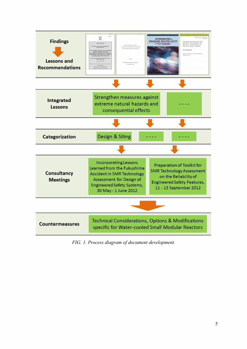
APPROACH TO THE PREPARATION OF THIS PUBLICATION 1.4.
The basis for the development of this publication is international experts’ discussion result
on the lessons learned from the Fukushima Daiichi accident which was produced in the
following three (3) Consultancy Meetings:
• Consultancy Meeting on ‘Incorporating Lessons Learned from the Fukushima
Accident in SMR Technology Assessment for Design of Engineered Safety
Systems’ held at the IAEA Headquarters on 30 May – 01 June 2012.
• Consultancy Meeting on ‘Preparation of Toolkit for SMR Technology
Assessment on the Reliability of Engineered Safety Features’ held at the IAEA
Headquarters on 11 – 13 September 2012.
• Consultancy Meeting on ‘Finalizing the TECDOC on Considerations to Enhance
the Performance of Engineered Safety Features of Small Modular Reactors in
Coping with Extreme External Events’ held at the IAEA Headquarters on 2 – 5
March 2015.
In these meetings, experts from Member States compiled and integrated the lessons learned
that have been previously identified, collected and published by the fact finding teams of
several organizations/institutes including reactor designers. The experts discussed and
produced integrated lessons learned and provided technical considerations and
countermeasure options on how to enhance the performance of ESFs of water cooled
SMRs [3]. The process diagram of the development of this publication is given in FIG. 1.
5
FIG. 1. Process diagram of document development.

6
2. OVERVIEW OF THE FUKUSHIMA DAIICHI ACCIDENT
The Fukushima Daiichi nuclear power plant (NPP) consists of six units of boiling water
reactors (BWRs) which were commissioned between 1971 and 1979, with power ratings
from 460 to 1100 MW(e). Unit 1 was a BWR/3 design with MARK I containment, Units
2–5 were BWR/4 designs with MARK I containment and Unit 6 was a BWR/5 design with
MARK II containment, which was the first unit in Japan with a capacity of 1100 MW(e).
A typical schematic diagram of BWR is shown in FIG. 2 [1]. 28
On March 11, 2011, at 14:46 (Japan Standard Time) a great earthquake of 9.0 Richter scale
shook the northeast coast of Japan and about one hour later two tsunami waves smashed
the Fukushima Daiichi NPP which was operated by Tokyo Electric Power Company
(TEPCO). About 10 minutes after the first wave, the second and largest wave, with a
run up height of 14–15 m, overwhelmed the seawalls and inundated the site. It engulfed
all structures and equipment located at the seafront, as well as the main buildings
(including the reactor, turbine and service buildings) at higher elevations. The wave
flooded and damaged the unhoused seawater pumps and motors at the seawater intake
locations on the shoreline. This meant that essential plant systems and components,
including the water cooled Emergency Diesel Generators (EDGs) could not be cooled to
ensure their continuous operation. Water entered and flooded buildings, including all the
reactor and turbine buildings, the common spent fuel storage building and diesel generator
building. The water damaged the buildings and the electrical and mechanical equipment
inside at ground level and on the lower floors. The damaged equipment included the EDGs
or their associated power connections, which resulted in the loss of emergency AC power.
Only one of the air cooled EDGs – that of Unit 6 – was unaffected by the flooding. It
remained in operation, continuing to supply emergency AC power to the Unit 6 safety
systems and allowing cooling of the reactor [1].
FIG. 2. Typical BWR with MARK I containment [1].
The earthquake and the tsunami impacted on multiple units at the Fukushima Daiichi NPP.
The tsunami also caused widespread destruction of buildings, doors, tanks, water intakes,
roads and other site infrastructures which lead to the loss of emergency core cooling
capability and eventually loss of the ultimate heat sink from the sea. Almost all power
7
sources and supporting systems and equipments expected to be activated in case of
accidents became inoperable. As a result of these events, Units 1–5 lost all AC power, a
situation referred to as a station blackout. The entire site was in a blackout situation after
the tsunami. The units at the Fukushima Daiichi NPP, similar to other plants of the same
age, were designed to withstand a station blackout for eight hours, based on the capacity of
the DC batteries in the reactor units. The units responded to the initiating event – the
earthquake and the concurrent loss of off-site power – as intended by the designers and as
stipulated in the operating procedures, except for some operator actions that were restricted
or delayed by the aftershocks [1].
When the earthquake occurred, Units 1, 2 and 3 were in operation at their rated power and
Units 4, 5 and 6 were in refueling outage. At Unit 4, all the fuels were stored in the spent
fuel pool (SFP) for the core shroud replacement work. The outage for Units 5 and 6 was
nearly complete and the fuels were already loaded into the reactor pressure vessels (RPV).
A few seconds after the earthquake, all the three operating units shutdown automatically by
the insertion of control blades. Turbine generators were also tripped and main steam
isolation valves (MSIVs) were closed. The earthquake had no significant impact on plant’s
structures, but it damaged the electrical grid infrastructures and interrupted electric supply
lines to the site, and the tsunami caused substantial destruction of the operational and
safety infrastructure on the site. The combined effect led to the loss of off-site and on-site
electrical power for all the six units which resulted in the loss of offsite power event, and
consequently the loss of the cooling function at the three operating reactor units as well as
at the spent fuel pools.
Units 1–3 were automatically isolated from their turbine systems due to the power
interruption, resulting in increases in the temperature and pressure of the reactors due to
the decay heat. The cooling of these reactors following the isolation was accomplished by
means of the following design and operational provisions:
• In Unit 1, as the reactor pressure increased, both loops of the IC system started
automatically and continued to cool the reactor. The operation of both ICs loops
lowered the reactor pressure and temperature so rapidly that the operators manually
stopped them, in accordance with procedures, in order to prevent thermal stress on the
RPV. Afterwards, only one of the loops was used by the operators to control the
cooling rate in a range prescribed by the procedures.
• In Units 2 and 3, the increase in reactor pressure automatically activated safety relief
valves, which were designed to protect the reactor from over pressurization by
releasing steam from the reactor vessel to the suppression pool section of the primary
containment vessel. This resulted in a decrease in the reactor water levels. The
operators manually activated the reactor core isolation cooling (RCIC) system in
accordance with procedures [1].
Following the loss of offsite power, EDGs provided essential power to all emergency
systems as designed for about 50 minutes until the big tsunami hit the Fukushima Daiichi
complex, flooding electrical switchboards, battery room and crippling EDGs.
Consequently, DC power was gradually lost in Units 1, 2 and 4 during the first 10–15
minutes of the flooding, making it difficult to cope with the station blackout. The
elevations and locations of structures and components at the Fukushima Daiichi NPP with
reference to the Onahama Port is shown in FIG. 3 [1].

8
FIG. 3. The elevations and locations of structures and components at the Fukushima
Daiichi NPP with reference to the Onahama Port [1].
When the reactors became isolated due to the closure of MSIVs, core cooling for Unit 1
was provided by the activation of IC which was under operator’s control before the
tsunami stroke. The schematic diagram of IC system is given in FIG. 4 [1]. However, loss
of DC power because of flooding in the battery room led to loss of indications for the
reactor water level, and made water level in the core unknown. The operators were not
certain whether or not the IC system properly functioned, so later on the operator decided
to terminate the IC system operation. As a result, there was no cooling mechanism to
remove decay heat from the reactor. In short, the fundamental safety function of core
cooling at Unit 1 was lost when the IC was stopped by the operators just before the
tsunami, and the Unit 1 core heated up from that time. The pressure in the containment
drywell rose rapidly as suppression pool became hotter. The high temperature and high
pressure level in the containment for an extended time damaged the electrical penetrations
and door/hatch seal which later led the leakage of hydrogen into the reactor building.
The volume of Mark I containment vessel, unlike Mark II or PWR, is small for its reactor
output and therefore the density of hydrogen may reach high enough under poor venting
condition to detonate in a short time once hydrogen begins to discharge during severe
accident condition. Nearly 24 hours after the station blackout, seawater injection and AC
power supply were connected to Unit 1. However, within minutes of connection, an
explosion in the Unit 1 reactor building damaged both of these arrangements before they
could be put in use.

9
FIG. 4. Isolation Condenser system [1].
Unit 2 had a different design for removing residual heat from the reactor core. The RCIC
system use steam from the RPV to drive a turbine which pumped water into the reactor
vessel. The schematic diagram of a RCIC system is provided in FIG. 5 [1]. The core
cooling after reactor trip and MSIV closure was provided by the RCIC system. The
operation of RCIC was manually started by operator a few minutes after the earthquake
and the system would automatically trip if a high reactor water level was achieved. When
tsunami reached the nuclear complex the DC distribution system was submerged in water
and lost its function. As a result all indications of important parameters gradually
disappeared and the high pressure coolant injection (HPCI) system which requires DC
power to operate also became unavailable. Consequently, operators were not sure if the
RCIC was operating because the indicator light had gone out. To confirm, a small team
was dispatched to inspect the system locally and it concluded that the RCIC was operating
and the reactor water level can be maintained.
FIG. 5. Reactor core isolation cooling system [1].

10
There are indications that, after about 68 hours, the RCIC system failed. It was therefore
no longer possible to inject water into the RPV because it was at high pressure. It is
estimated that the Unit 2 reactor core began to melt about 76 hours after the tsunami. The
accident progression at the Fukushima Daiichi nuclear power plant is briefly depicted in
FIG. 6.
FIG. 6. The accident progressions at the Fukushima Daiichi nuclear plant complex.
Situation in Unit 3 was similar to that in Unit 2 except that some DC power was still
functioning after the tsunami. At the beginning the core cooling was provided by RCIC
which was manually actuated by operator about 20 minutes after the reactor scram. This
RCIC provided injection to the core until it automatically stopped when a high reactor
water level was reached. The tsunami then caused the loss of some DC power systems but
fortunately the indications for pressure and reactor water level were not affected. An ‘on
and off’ operation for RCIC was used by operator to maintain the water level at about 4
meters above the top of active fuel (TAF). Pressure inside the reactor vessel was controlled
by safety relief valves (SRVs). However the condition did not stay long. After 14 hours of
continued operation of the emergency HPCI system, the Unit 3 operators became
concerned about the reliability and possible failure of the system’s turbine powering the
injection pump, which was by then operating at low reactor steam pressure. The concern
was related to the possibility of turbine damage and the creation of a release path from the
reactor vessel. This would result in an uncontrollable release of radioactive steam directly
outside the primary containment. This concern was heightened when the turbine did not
11
automatically stop, as it was designed to, when the reactor pressure decreased below the
automatic shutoff pressure. Consequently, the operators decided to stop the HPCI system
and instead use the alternative means of injection at low pressure (the diesel driven fire
pump). The operators thought this could be achieved without interruption of core cooling,
since the reactor pressure was already below that of the diesel driven fire pump and could
be kept low by the use of pressure relief valves. The Unit 3 emergency high pressure core
injection system was therefore turned off by the operators, who then started their attempts
to open the pressure relief valves. However, all attempts to open the pressure relief valves
failed, and reactor pressure quickly increased above the level at which the diesel driven fire
pump could inject, stopping the cooling of the Unit 3 core about 35 hours after the station
blackout. Faced with this setback, the operators tried to return to injection via the
emergency HPCI system but were unsuccessful. On 14 March, an explosion occurred in
the upper part of the Unit 3 reactor building, destroying the structure above the service
floor and injuring workers. In addition to the destruction of the alternative water injection
arrangement, the capability to vent the containment in Unit 2 was also lost as a result of the
explosion, which affected the previously set up Unit 2 containment venting path. After the
explosion, the isolation valve on the Unit 2 vent line was discovered to be closed and could
not be reopened [1].
Following the loss of IC, RCIC and HPCI systems in Units 1, 2 and 3, the plant workers
prepared to inject water into reactor vessels via fire hoses for emergency cooling.
However, situation on the site was far beyond originally estimated conditions in the
accident management. Injections of water to the reactor vessels were delayed by on-site
difficulties. The reactor and containment pressure was very high so that depressurization
and venting were needed before the injection could be performed. Meanwhile some
segments of fuel rods were already uncovered, overheated and damaged, which resulted in
exothermic reaction between steam and zirconium thus producing hydrogen gas. Despite
the efforts of the operators to maintain control, the reactor cores in Units 1–3 overheated,
the nuclear fuel melted and the three containment vessels were breached. The high
containment pressure caused leakage of the hydrogen and other volatile radionuclides to
the reactor building structure. Hydrogen was released from the reactor pressure vessels,
leading to explosions inside the reactor buildings in Units 1, 3 and 4 that damaged
structures and equipment and injured personnel. Radionuclides were released from the
plant to the atmosphere and were deposited on land and on the ocean. There were also
direct releases into the sea. Another explosion occurred in Unit 2 around its suppression
pool due to the containment overpressure as venting could not be performed in this unit.
Units 5 & 6 survived the accident due to the air-cooled EDG of Unit 6.
The Fukushima Daiichi accident demonstrated that extreme natural hazards have the
potential to invalidate or impair multiple levels of defence in depth (DiD). The design of
the Fukushima Daiichi nuclear power plant provided equipment and systems for the first
three levels of DiD: (1) equipment intended to provide reliable normal operation; (2)
equipment intended to return the plant to a safe state after an abnormal event; and (3)
safety systems intended to manage accident conditions. The design bases were derived
using a range of postulated hazards; however, external hazards such as tsunamis were not
fully addressed. Consequently, the flooding resulting from the tsunami simultaneously
challenged the first three protective levels of DiD, resulting in common cause failures of
equipment and systems at each of the three levels. The failure to provide sufficient means
of protection at each level of DiD resulted in severe reactor damage in Units 1, 2 and 3 and
in significant radioactive releases from these units. A systematic identification and
assessment of external hazards and robust protection against these hazards needs therefore
12
to be considered for all levels of DiD. Furthermore, the accident showed that alternative
design provisions and accident management capabilities could still ensure the supply of
cooling water to the reactor even if all prime safety systems designed to protect the reactor
against accidents were lost [1].
Stress tests were carried out in many IAEA member states with operable NPPs to reassess
the design of NPPs against site specific extreme natural hazards, installing additional
backup sources of electrical power and supplies of water, and strengthening the protection
of plants against extreme external events. There is widespread recognition that everything
humanly possible must be done to ensure that no such accident ever happens again. IAEA
safety standards embody an international consensus on what constitutes a high level of
safety. They were reviewed after the accident by the Commission on Safety Standards.
Worldwide operating experience has shown instances where natural hazards have exceeded
the design basis for a NPP [1].
13
3. REVIEW OF ENGINEERED SAFETY FEATURE DESIGN OF SMALL
MODULAR REACTORS AND ADVANCED REACTORS
Engineered safety feature (ESF) of NPP is a set of means to protect the public from
radioactive fission products in the event of accidents. Its primary functions are to localize,
control, mitigate and terminate the consequences of postulated accidents and maintain
radiation exposure levels below allowable limits. Various designs and concepts of ESFs
are used in different reactors and there are similarities among them. The variations mainly
come from the type and safety characteristic of the reactor, power size, availability of
passive system and approaches on how to address the accidents. The following is a
discussion on the ESF designs of integral PWR type SMRs and advanced large reactors. In
general, the ESF consists of several functional systems, i.e. trip system, residual heat
removal system, safety injection system, and containment system. Advanced water cooled
reactor designs have also added severe accident mitigation features to deal with beyond
design basis accidents. With regard to the lesson learned from the Fukushima Daiichi
accident, the discussion is focused on water cooled reactor technology. Several water
cooled SMRs and advanced reactors are reviewed including integral PWR type SMRs,
large PWRs and BWRs. The intention is to gather insights on the capabilities of the
engineered safety system design to see if any improvements are needed based on the
lessons learned from the Fukushima Daiichi accident.
TRIP AND SAFETY SHUTDOWN SYSTEMS 3.1.
Generally, water cooled reactors use control rods as the main reactivity control system to
shut down the reactor under normal and emergency conditions. Rods made from neutron
absorbing materials are inserted in reactor core using control rod drive mechanism
(CRDM) or gravity to cease the nuclear chain reaction. Most of CRDMs in existing
designs are located outside the pressure vessel, either on the upperside (as in PWR) or
below the vessel (as in BWR), using welded penetrations in the vessel. Their postulated
worst case failure causes a single absorber control rod cluster/blade ejection accident,
resulting in a small LOCA as well as instantaneous insertion of positive reactivity. A new
design is introduced recently for integral PWR type SMRs where the CRDM is placed
inside the vessel to eliminate these penetration and the consequences of their failure. This
technique inherently removes possibility of rod ejection accident and the consequent
LOCA as penetrations in the reactor vessel closure head are eliminated. SMR designs
which implement in-vessel CRDM technology, among others, are CAREM25, IRIS,
mPower and Westinghouse SMR.
In addition water cooled reactors have a diverse alternate mechanism to ensure fission
termination, if the CRDM fails. The mechanism is mostly injection of dissolved boron into
primary system by active or passive driving force. SMR designs which implement passive
method for their secondary shutdown systems, among others are CAREM25, IRIS and
Westinghouse SMR. One of the designs that uses active injection system is SMART.
RESIDUAL HEAT REMOVAL SYSTEM 3.2.
Residual heat removal through steam generator and heat exchanger 3.2.1.
submerged in water pool
Some SMR designs passively remove decay heat through pairing the steam generators
(SGs) with heat exchangers (HXs) immersed in a water pool as shown in FIG. 7. Steam

14
produced by decay heat in the SG is routed to the heat exchangers where it is condensed.
The condensate flows back to the SG through SG feed water inlet. SMR designs which
implement this method, among others, are the passive emergency heat removal system
(EHRS) of IRIS, the passive residual heat removal (PRHR) system of SMART and the
decay heat removal system (DHRS) of NuScale.
FIG. 7. Emergency heat removal system through steam generator.
Residual heat removal using passively cooled condenser 3.2.2.
If a loss of heat sink condition occurs, the continuous reactor core decay heat produces
steam after some time. As a result the system pressure increases. The core needs to be
cooled down by removing the decay heat. Some SMR and new large NPP designs use
passive condensers which are immersed in water pool and connected to the upper dome of
the vessel, thus forming a natural circulation loop to cool down the primary system, as
shown in FIG. 8. When the valves open, the steam goes to the condenser tubes transferring
the heat to the water in the pool. As the steam condenses the water in the tubes it returns to
the vessel by gravity effect.
The SMR designs which implement passive condenser approach for its residual heat
removal system (RHRS) include CAREM25 and NuScale. The same principle is also
implemented for the IC of BWR plant.
Passively cooled condenser is also used by large PWR reactor (such as PRHR of AP1000).
The hot leg and cold leg of the reactor are connected to the heat exchanger inlet and outlet,
respectively. The condenser is submerged in water pool which is located above the reactor
vessel to establish a natural circulation path.
Residual heat removal using pump and heat exchanger 3.2.3.
Conventional approach for residual heat removal system is to use active means usually
consisting of pumps, valves, HXs and related piping. This approach is used by many
existing advanced light-water cooled reactors.
15
FIG. 8. Residual heat removal through condenser.
SAFETY INJECTION SYSTEM 3.3.
High pressure injection system 3.3.1.
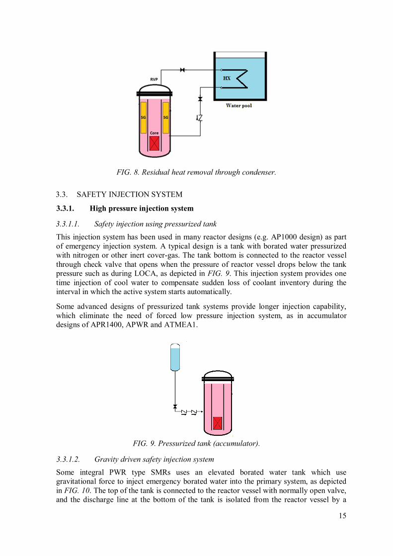
3.3.1.1. Safety injection using pressurized tank
This injection system has been used in many reactor designs (e.g. AP1000 design) as part
of emergency injection system. A typical design is a tank with borated water pressurized
with nitrogen or other inert cover-gas. The tank bottom is connected to the reactor vessel
through check valve that opens when the pressure of reactor vessel drops below the tank
pressure such as during LOCA, as depicted in FIG. 9. This injection system provides one
time injection of cool water to compensate sudden loss of coolant inventory during the
interval in which the active system starts automatically.
Some advanced designs of pressurized tank systems provide longer injection capability,
which eliminate the need of forced low pressure injection system, as in accumulator
designs of APR1400, APWR and ATMEA1.
FIG. 9. Pressurized tank (accumulator).
3.3.1.2. Gravity driven safety injection system
Some integral PWR type SMRs uses an elevated borated water tank which use
gravitational force to inject emergency borated water into the primary system, as depicted
in FIG. 10. The top of the tank is connected to the reactor vessel with normally open valve,
and the discharge line at the bottom of the tank is isolated from the reactor vessel by a

16
normally closed valve. During an emergency situation, the bottom valve opens and as a
result the borated water flows down to the vessel, simultaneously cooling the core and
terminating the fission. The SMR designs which implement this concept, among others, are
the emergency boration tank of IRIS and the core make up tank of Westinghouse SMR.
FIG. 10. Gravity driven injection tank (core make-up tank).
3.3.1.3. Injection system using high head pump
A conventional active approach for safety injection system along with secondary shutdown
function is used in many existing reactors. This approach requires electric powered pump
to inject boron solution from emergency boron tank into the reactor vessel, as illustrated in
FIG. 11. Advanced reactor designs which use such active system approach are boron
injection system of SMART.
3.3.1.4. Turbine driven injection system
In addition to gravity driven system or pressurized tank system, a core injection system is
composed using a turbine driven pump. The steam from the reactor pressure vessel drives a
pump which transfers water from a storage tank/pool into the reactor vessel. This approach
of injection system is widely used in BWR reactors and known as the reactor core isolation
cooling (RCIC) system.
FIG. 11. Boron injection system using high head pump.
17
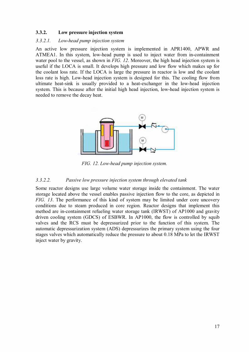
Low pressure injection system 3.3.2.
3.3.2.1. Low-head pump injection system
An active low pressure injection system is implemented in APR1400, APWR and
ATMEA1. In this system, low-head pump is used to inject water from in-containment
water pool to the vessel, as shown in FIG. 12. Moreover, the high head injection system is
useful if the LOCA is small. It develops high pressure and low flow which makes up for
the coolant loss rate. If the LOCA is large the pressure in reactor is low and the coolant
loss rate is high. Low-head injection system is designed for this. The cooling flow from
ultimate heat-sink is usually provided to a heat-exchanger in the low-head injection
system. This is because after the initial high head injection, low-head injection system is
needed to remove the decay heat.
FIG. 12. Low-head pump injection system.
3.3.2.2. Passive low pressure injection system through elevated tank
Some reactor designs use large volume water storage inside the containment. The water
storage located above the vessel enables passive injection flow to the core, as depicted in
FIG. 13. The performance of this kind of system may be limited under core uncovery
conditions due to steam produced in core region. Reactor designs that implement this
method are in-containment refueling water storage tank (IRWST) of AP1000 and gravity
driven cooling system (GDCS) of ESBWR. In AP1000, the flow is controlled by squib
valves and the RCS must be depressurized prior to the function of this system. The
automatic depressurization system (ADS) depressurizes the primary system using the four
stages valves which automatically reduce the pressure to about 0.18 MPa to let the IRWST
inject water by gravity.
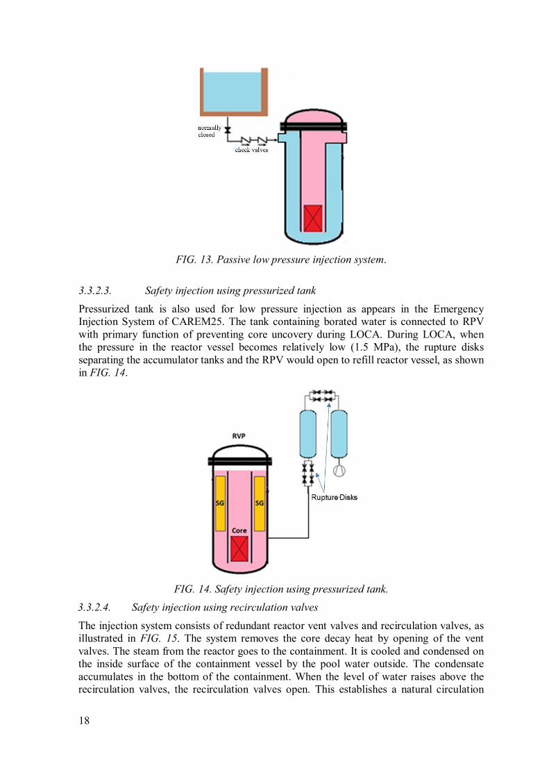
18
FIG. 13. Passive low pressure injection system.
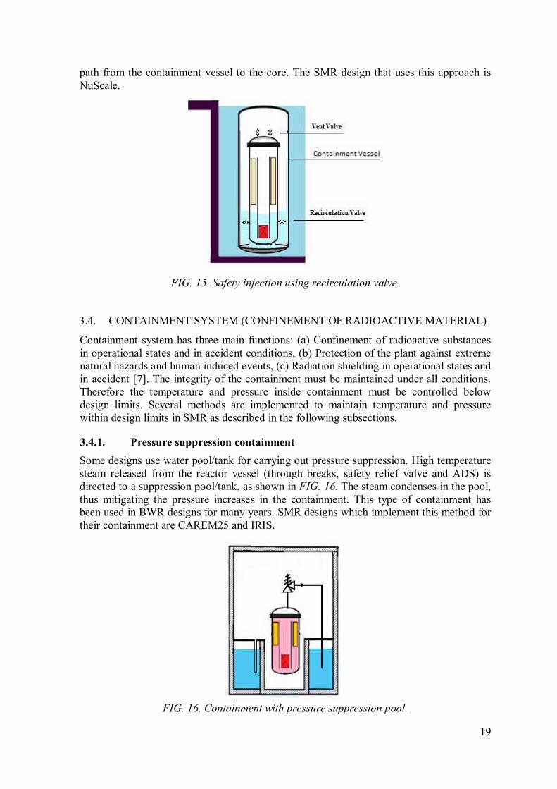
3.3.2.3. Safety injection using pressurized tank
Pressurized tank is also used for low pressure injection as appears in the Emergency
Injection System of CAREM25. The tank containing borated water is connected to RPV
with primary function of preventing core uncovery during LOCA. During LOCA, when
the pressure in the reactor vessel becomes relatively low (1.5 MPa), the rupture disks
separating the accumulator tanks and the RPV would open to refill reactor vessel, as shown
in FIG. 14.
FIG. 14. Safety injection using pressurized tank.
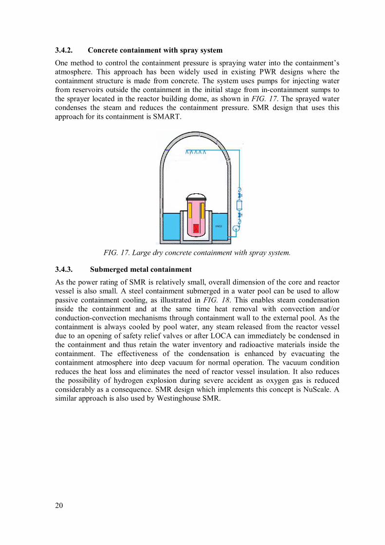
3.3.2.4. Safety injection using recirculation valves
The injection system consists of redundant reactor vent valves and recirculation valves, as
illustrated in FIG. 15. The system removes the core decay heat by opening of the vent
valves. The steam from the reactor goes to the containment. It is cooled and condensed on
the inside surface of the containment vessel by the pool water outside. The condensate
accumulates in the bottom of the containment. When the level of water raises above the
recirculation valves, the recirculation valves open. This establishes a natural circulation
19
path from the containment vessel to the core. The SMR design that uses this approach is
NuScale.
FIG. 15. Safety injection using recirculation valve.
CONTAINMENT SYSTEM (CONFINEMENT OF RADIOACTIVE MATERIAL) 3.4.
Containment system has three main functions: (a) Confinement of radioactive substances
in operational states and in accident conditions, (b) Protection of the plant against extreme
natural hazards and human induced events, (c) Radiation shielding in operational states and
in accident [7]. The integrity of the containment must be maintained under all conditions.
Therefore the temperature and pressure inside containment must be controlled below
design limits. Several methods are implemented to maintain temperature and pressure
within design limits in SMR as described in the following subsections.
Pressure suppression containment 3.4.1.
Some designs use water pool/tank for carrying out pressure suppression. High temperature
steam released from the reactor vessel (through breaks, safety relief valve and ADS) is
directed to a suppression pool/tank, as shown in FIG. 16. The steam condenses in the pool,
thus mitigating the pressure increases in the containment. This type of containment has
been used in BWR designs for many years. SMR designs which implement this method for
their containment are CAREM25 and IRIS.
FIG. 16. Containment with pressure suppression pool.
20
Concrete containment with spray system 3.4.2.
One method to control the containment pressure is spraying water into the containment’s
atmosphere. This approach has been widely used in existing PWR designs where the
containment structure is made from concrete. The system uses pumps for injecting water
from reservoirs outside the containment in the initial stage from in-containment sumps to
the sprayer located in the reactor building dome, as shown in FIG. 17. The sprayed water
condenses the steam and reduces the containment pressure. SMR design that uses this
approach for its containment is SMART.
FIG. 17. Large dry concrete containment with spray system.
Submerged metal containment 3.4.3.
As the power rating of SMR is relatively small, overall dimension of the core and reactor
vessel is also small. A steel containment submerged in a water pool can be used to allow
passive containment cooling, as illustrated in FIG. 18. This enables steam condensation
inside the containment and at the same time heat removal with convection and/or
conduction-convection mechanisms through containment wall to the external pool. As the
containment is always cooled by pool water, any steam released from the reactor vessel
due to an opening of safety relief valves or after LOCA can immediately be condensed in
the containment and thus retain the water inventory and radioactive materials inside the
containment. The effectiveness of the condensation is enhanced by evacuating the
containment atmosphere into deep vacuum for normal operation. The vacuum condition
reduces the heat loss and eliminates the need of reactor vessel insulation. It also reduces
the possibility of hydrogen explosion during severe accident as oxygen gas is reduced
considerably as a consequence. SMR design which implements this concept is NuScale. A
similar approach is also used by Westinghouse SMR.

21
FIG. 18. Submerged metal containment.
Passively cooled large volume metal containment 3.4.4.
Variant of metal containment is used by some advanced reactors. A large volume metal
containment surrounded by reinforced concrete building is used to withstand the pressure
increase during LOCA. The metal containment is passively cooled by air flow or by water
spray, as shown in FIG. 19. Thus steam will condense at the inner surface of the
containment. Containment design of this approach is utilized by AP1000. Similar concept
is also used by the mPower where the upper hemisphere of its metal containment is
passively cooled by water.
FIG. 19. Passively cooled large volume metal containment.
SEVERE ACCIDENT MITIGATION FEATURES 3.5.
In-vessel retention system 3.5.1.
Most of the advance reactor designs use strategies to deal with severe accident conditions.
One of them is the implementation of in-vessel corium retention feature. In this strategy,
Internal condensation and
natural recirculation
22
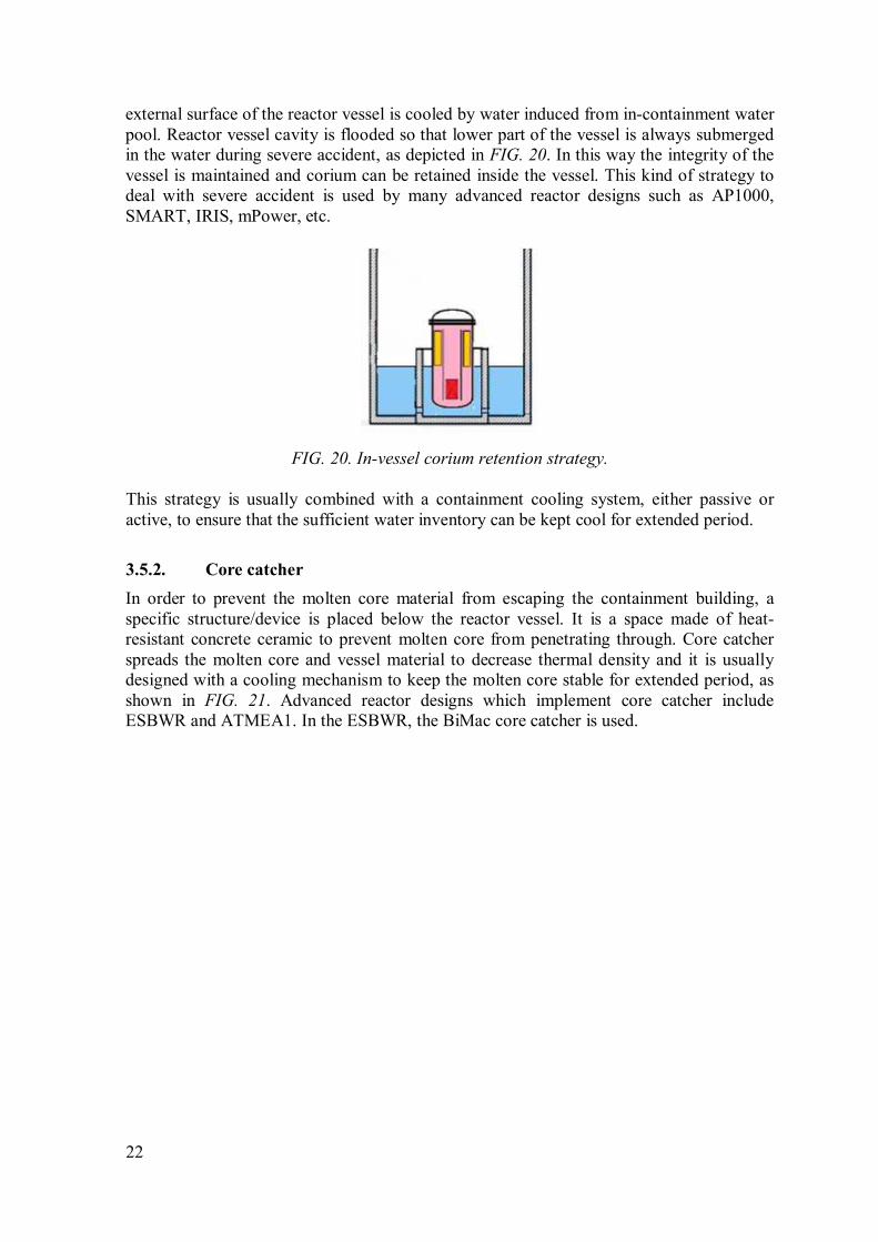
external surface of the reactor vessel is cooled by water induced from in-containment water
pool. Reactor vessel cavity is flooded so that lower part of the vessel is always submerged
in the water during severe accident, as depicted in FIG. 20. In this way the integrity of the
vessel is maintained and corium can be retained inside the vessel. This kind of strategy to
deal with severe accident is used by many advanced reactor designs such as AP1000,
SMART, IRIS, mPower, etc.
FIG. 20. In-vessel corium retention strategy.
This strategy is usually combined with a containment cooling system, either passive or
active, to ensure that the sufficient water inventory can be kept cool for extended period.
Core catcher 3.5.2.
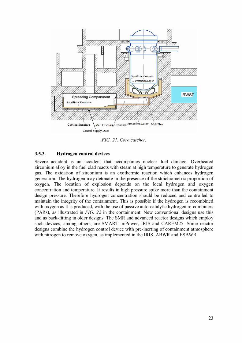
In order to prevent the molten core material from escaping the containment building, a
specific structure/device is placed below the reactor vessel. It is a space made of heat-
resistant concrete ceramic to prevent molten core from penetrating through. Core catcher
spreads the molten core and vessel material to decrease thermal density and it is usually
designed with a cooling mechanism to keep the molten core stable for extended period, as
shown in FIG. 21. Advanced reactor designs which implement core catcher include
ESBWR and ATMEA1. In the ESBWR, the BiMac core catcher is used.
23
FIG. 21. Core catcher.
Hydrogen control devices 3.5.3.
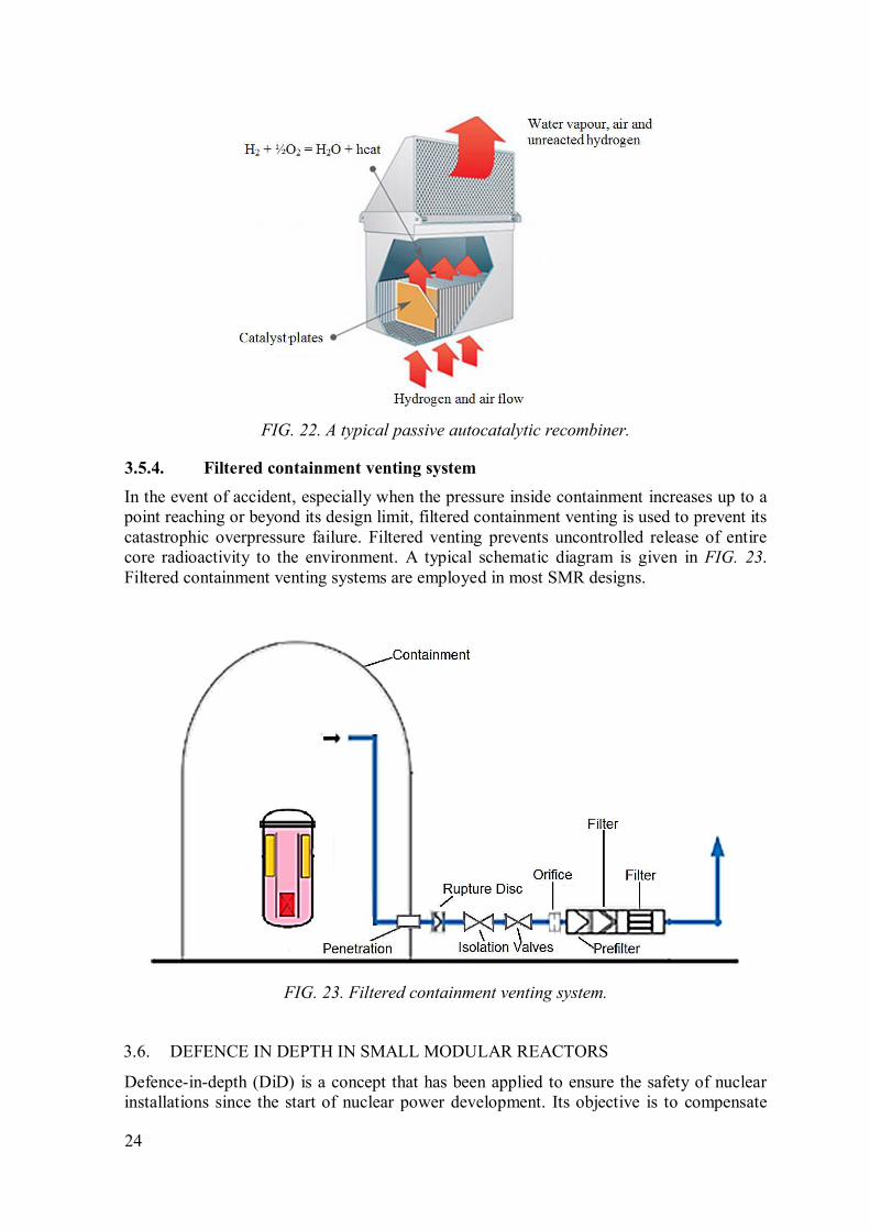
Severe accident is an accident that accompanies nuclear fuel damage. Overheated
zirconium alloy in the fuel clad reacts with steam at high temperature to generate hydrogen
gas. The oxidation of zirconium is an exothermic reaction which enhances hydrogen
generation. The hydrogen may detonate in the presence of the stoichiometric proportion of
oxygen. The location of explosion depends on the local hydrogen and oxygen
concentration and temperature. It results in high pressure spike more than the containment
design pressure. Therefore hydrogen concentration should be reduced and controlled to
maintain the integrity of the containment. This is possible if the hydrogen is recombined
with oxygen as it is produced, with the use of passive auto-catalytic hydrogen re-combiners
(PARs), as illustrated in FIG. 22 in the containment. New conventional designs use this
and as back-fitting in older designs. The SMR and advanced reactor designs which employ
such devices, among others, are SMART, mPower, IRIS and CAREM25. Some reactor
designs combine the hydrogen control device with pre-inerting of containment atmosphere
with nitrogen to remove oxygen, as implemented in the IRIS, ABWR and ESBWR.
24
FIG. 22. A typical passive autocatalytic recombiner.
Filtered containment venting system 3.5.4.
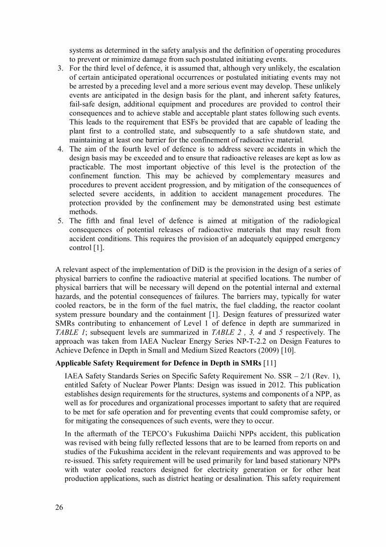
In the event of accident, especially when the pressure inside containment increases up to a
point reaching or beyond its design limit, filtered containment venting is used to prevent its
catastrophic overpressure failure. Filtered venting prevents uncontrolled release of entire
core radioactivity to the environment. A typical schematic diagram is given in FIG. 23.
Filtered containment venting systems are employed in most SMR designs.
FIG. 23. Filtered containment venting system.
DEFENCE IN DEPTH IN SMALL MODULAR REACTORS 3.6.
Defence-in-depth (DiD) is a concept that has been applied to ensure the safety of nuclear
installations since the start of nuclear power development. Its objective is to compensate

25
for potential human and equipment failures by means of several levels of protection. DiD
is an established safety philosophy in which multiple lines of defence, safety margins, and
compensatory measures are applied to the design, construction, operation, maintenance,
and regulation of nuclear plants to prevent and to mitigate accidents and to assure that the
adequate protection of public health and safety. Defence is provided by multiple and
independent means at each level of protection. The concept of DiD, as applied to all safety
activities, whether organizational, behavioral or design related, ensures that they are
subject to overlapping provisions, so that if a failure were to occur, it would be detected
and compensated for or corrected by appropriate measures. Application of the concept of
DiD throughout design and operation provides a graded protection against a wide variety
of transients, anticipated operational occurrences and accidents, including those resulting
from equipment failure or human action within the plant, and events that originate outside
the plant [1]. In SMR designs, as in larger reactor designs, the DiD strategy is used to
protect the public and environment from accidental releases of radiation. Nearly all SMRs
designs seek to strengthen the first and subsequent levels of defence by incorporating
inherent and passive safety features. Certain common characteristics of smaller reactors
lend themselves to inherent and passive safety features, such as relatively smaller core
sizes enabling integral coolant system layouts and larger reactor surface-to-volume ratios
or lower core power densities which facilitate passive decay heat removal. Using the
benefits of such features, the main goal is to eliminate or prevent, through design, as many
accident initiators and accident consequences as possible. Remaining plausible accident
initiators and consequences are then addressed by appropriate combinations of active and
passive safety systems. The intended outcome is greater plant simplicity with high safety
levels that, in turn, may allow reduced emergency requirements off-site. It should be noted
that an approach to maximize the use of inherent safety. Application of the concept of DiD
in the design of a plant provides a series of levels of defence (inherent features, equipment
and procedures) aimed at preventing accidents and ensuring appropriate protection in the
event that prevention fails.
1. The aim of the first level of defence is to prevent deviations from normal operation,
and to prevent system failures. This leads to the requirement that the plant be soundly
and conservatively designed, constructed, maintained and operated in accordance with
appropriate quality levels and engineering practices, such as the application of
redundancy, independence and diversity. To meet this objective, careful attention is
paid to the selection of appropriate design codes and materials, and to the control of
fabrication of components and of plant construction. Design options that can
contribute to reducing the potential for internal hazards (e.g. controlling the response
to a postulated initiating event), to reducing the consequences of a given postulated
initiating event, or to reducing the likely release source term following an accident
sequence contribute at this level of defence. Attention is also paid to the procedures
involved in the design, fabrication, construction and in-service plant inspection,
maintenance and testing, to the ease of access for these activities, to the way the plant
is operated and to how operational experience is utilized. This whole process is
supported by a detailed analysis which determines the operational and maintenance
requirements for the plant.
2. The aim of the second level of defence is to detect and intercept deviations from
normal operational states in order to prevent anticipated operational occurrences from
escalating to accident conditions. This is in recognition of the fact that some
postulated initiating events are likely to occur over the service lifetime of an NPP,
despite the care taken to prevent them. This level necessitates the provision of specific
26
systems as determined in the safety analysis and the definition of operating procedures
to prevent or minimize damage from such postulated initiating events.
3. For the third level of defence, it is assumed that, although very unlikely, the escalation
of certain anticipated operational occurrences or postulated initiating events may not
be arrested by a preceding level and a more serious event may develop. These unlikely
events are anticipated in the design basis for the plant, and inherent safety features,
fail-safe design, additional equipment and procedures are provided to control their
consequences and to achieve stable and acceptable plant states following such events.
This leads to the requirement that ESFs be provided that are capable of leading the
plant first to a controlled state, and subsequently to a safe shutdown state, and
maintaining at least one barrier for the confinement of radioactive material.
4. The aim of the fourth level of defence is to address severe accidents in which the
design basis may be exceeded and to ensure that radioactive releases are kept as low as
practicable. The most important objective of this level is the protection of the
confinement function. This may be achieved by complementary measures and
procedures to prevent accident progression, and by mitigation of the consequences of
selected severe accidents, in addition to accident management procedures. The
protection provided by the confinement may be demonstrated using best estimate
methods.
5. The fifth and final level of defence is aimed at mitigation of the radiological
consequences of potential releases of radioactive materials that may result from
accident conditions. This requires the provision of an adequately equipped emergency
control [1].
A relevant aspect of the implementation of DiD is the provision in the design of a series of
physical barriers to confine the radioactive material at specified locations. The number of
physical barriers that will be necessary will depend on the potential internal and external
hazards, and the potential consequences of failures. The barriers may, typically for water
cooled reactors, be in the form of the fuel matrix, the fuel cladding, the reactor coolant
system pressure boundary and the containment [1]. Design features of pressurized water
SMRs contributing to enhancement of Level 1 of defence in depth are summarized in
TABLE 1; subsequent levels are summarized in TABLE 2 , 3, 4 and 5 respectively. The
approach was taken from IAEA Nuclear Energy Series NP-T-2.2 on Design Features to
Achieve Defence in Depth in Small and Medium Sized Reactors (2009) [10].
Applicable Safety Requirement for Defence in Depth in SMRs [11]
IAEA Safety Standards Series on Specific Safety Requirement No. SSR – 2/1 (Rev. 1),
entitled Safety of Nuclear Power Plants: Design was issued in 2012. This publication
establishes design requirements for the structures, systems and components of a NPP, as
well as for procedures and organizational processes important to safety that are required
to be met for safe operation and for preventing events that could compromise safety, or
for mitigating the consequences of such events, were they to occur.
In the aftermath of the TEPCO’s Fukushima Daiichi NPPs accident, this publication
was revised with being fully reflected lessons that are to be learned from reports on and
studies of the Fukushima accident in the relevant requirements and was approved to be
re-issued. This safety requirement will be used primarily for land based stationary NPPs
with water cooled reactors designed for electricity generation or for other heat
production applications, such as district heating or desalination. This safety requirement
27
may also be applied, with judgement, to other reactor types, to determine the
requirements that have to be considered in developing the design.
Requirement 7 of SSR–2/1 (Rev. 1) establishes the following requirements on
application of defence in depth.
“The design of a NPP shall incorporate defence in depth. The levels of defence in depth
shall be independent as far as is practicable”
Paragraph 4.9 requires that the defence in depth concept shall be applied to provide
several levels of defence that are aimed at preventing consequences of accidents that
could lead to harmful effects on people and the environment, and ensuring that
appropriate measures are taken for the protection of people and the environment and for
the mitigation of consequences in the event that prevention fails.
Paragraph 4.10 requires that the design shall take due account of the fact that the
existence of multiple levels of defence is not a basis for continued operation in the
absence of one level of defence. All levels of defence in depth shall be kept available at
all times and any relaxations shall be justified for specific modes of operation.
Paragraph 4.11 requires the design:
a) Shall provide for multiple physical barriers to the release of radioactive material
to the environment;
b) Shall be conservative, and the construction shall be of high quality, so as to
provide assurance that failures and deviations from normal operation are
minimized, that accidents are prevented as far as is practicable and that a small
deviation in a plant parameter does not lead to a cliff edge effect;
c) Shall provide for the control of plant behaviour by means of inherent and
engineered features, such that failures and deviations from normal operation
requiring actuation of safety systems are minimized or excluded by design, to
the extent possible;
d) Shall provide for supplementing the control of the plant by means of automatic
actuation of safety systems, such that failures and deviations from normal
operation that exceed the capability of control systems can be controlled with a
high level of confidence, and the need for operator actions in the early phase of
these failures or deviations from normal operation is minimized;
e) Shall provide for systems, structures and components and procedures to control
the course of and, as far as practicable, to limit the consequences of failures and
deviations from normal operation that exceed the capability of safety systems;
f) Shall provide multiple means for ensuring that each of the fundamental safety
functions is performed, thereby ensuring the effectiveness of the barriers and
mitigating the consequences of any failure or deviation from normal operation.
Paragraph 4.13 requires that the design shall be such as to ensure, as far as is
practicable, that the first, or at most the second, level of defence is capable of
preventing an escalation to accident conditions for all failures or deviations from normal
operation that are likely to occur over the operating lifetime of the NPP.

28
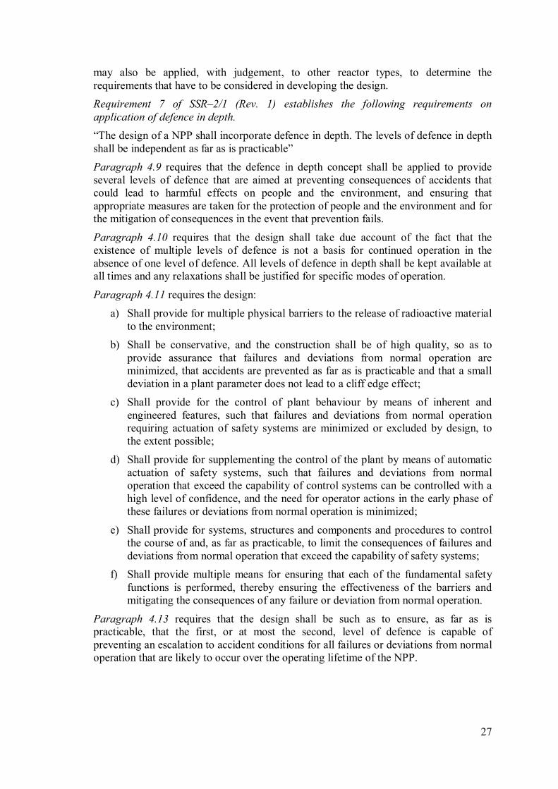
TABLE 1. DESIGN FEATURES OF WATER COOLED SMR DESIGNS CONTRIBUTING TO LEVEL 1 OF
DEFENCE IN DEPTH
TABLE 1 (cont.)
No. Design features Design objectives SMR designs Relevant safety
requirements
1.
Elimination of liquid
boron reactivity control system
Exclusion of inadvertent
reactivity insertion as a result of boron dilution
KLT-40S, CAREM25,
IRIS, IMR, ABV-6M, RITM-200, VK-300,
mPower, SMR-160,
Flexblue.
IAEA Safety
Standards Series Specific Safety
Requirements No.
SSR–2/1 (Rev. 1),
Safety of Nuclear
Power Plants: Design
Requirement 20,
Paragraph 4.11 [(a)
and (b)] and relevant
Paragraphs. [11]
2. Relatively low core
power density
Larger thermal-hydraulic
margins
IRIS, CAREM25,
NuScale, mPower
3.
High thermal
conductivity of fuel
Relatively low temperature
of fuel and High margin to
fuel failure
KLT-40S
4.
Gas pressurizer system Pressurizer heater
potentially unreliable
component
KLT-40S, RITM-200
5.
Integral design of
primary circuit with in-
vessel location of steam
generators
Exclusion of large-break,
loss of coolant accidents
(LOCA)
CAREM25, IRIS,
ACP100, DMS, IMR,
SMART, ABV-6M,
RITM-200, VK-300, UNITHERM, NuScale,
mPower, Westinghouse
SMR
6. Compact modular design
of the reactor unit
Decreased probability of
LOCA
KLT-40S, ELENA
7.
Primary pressure
boundary enclosed in a
pressurized, low enthalpy
containment
Elimination of LOCA
resulting from failure of the
primary coolant pressure
boundary
NuScale
8. Leak tight reactor
coolant system
Decreased probability of
LOCA
KLT-40S
9.
Internal horizontal, fully
immersed pumps
Elimination of pump
seizure, rotor lock, and seal
LOCA
IRIS, SMART,
Westinghouse SMR
10. Vertical Canned motor
pump
Decreased probability of
seal LOCA
ACP100, KLT-40S,VBER-
300, mPower
11. Flow restriction devices in the primary pipelines
Limitation of the break flow KLT-40S
12.
Natural circulation in
normal operation
Elimination of loss of flow
accidents
CAREM25, DMS, IMR,
ABV-6M, VK-300,
UNITHERM, ELENA,
NuScale, SMR-160
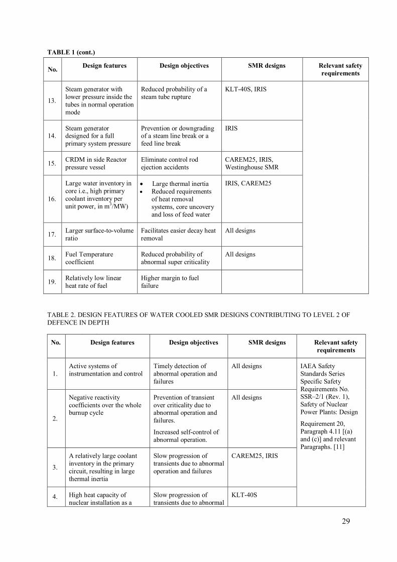
29
TABLE 1 (cont.)
No. Design features Design objectives SMR designs Relevant safety
requirements
13.
Steam generator with
lower pressure inside the
tubes in normal operation
mode
Reduced probability of a
steam tube rupture
KLT-40S, IRIS
14. Steam generator designed for a full
primary system pressure
Prevention or downgrading of a steam line break or a
feed line break
IRIS
15. CRDM in side Reactor
pressure vessel
Eliminate control rod
ejection accidents
CAREM25, IRIS,
Westinghouse SMR
16.
Large water inventory in
core i.e., high primary
coolant inventory per
unit power, in m3/MW)
• Large thermal inertia
• Reduced requirements
of heat removal
systems, core uncovery
and loss of feed water
IRIS, CAREM25
17. Larger surface-to-volume
ratio
Facilitates easier decay heat
removal
All designs
18. Fuel Temperature
coefficient
Reduced probability of
abnormal super criticality
All designs
19. Relatively low linear
heat rate of fuel
Higher margin to fuel
failure
TABLE 2. DESIGN FEATURES OF WATER COOLED SMR DESIGNS CONTRIBUTING TO LEVEL 2 OF
DEFENCE IN DEPTH
TABLE 2 (cont.)
No. Design features Design objectives SMR designs Relevant safety
requirements
1.
Active systems of
instrumentation and control
Timely detection of
abnormal operation and
failures
All designs IAEA Safety
Standards Series
Specific Safety
Requirements No. SSR–2/1 (Rev. 1),
Safety of Nuclear
Power Plants: Design
Requirement 20,
Paragraph 4.11 [(a)
and (c)] and relevant
Paragraphs. [11]
2.
Negative reactivity
coefficients over the whole burnup cycle
Prevention of transient
over criticality due to abnormal operation and
failures.
Increased self-control of
abnormal operation.
All designs
3.
A relatively large coolant
inventory in the primary
circuit, resulting in large
thermal inertia
Slow progression of
transients due to abnormal
operation and failures
CAREM25, IRIS
4. High heat capacity of
nuclear installation as a
Slow progression of
transients due to abnormal
KLT-40S

30
TABLE 2 (cont.)
No. Design features Design objectives SMR designs Relevant safety
requirements
whole operation and failures
5.
Implementation of the leak
before break concept
Facilitate implementation
of leak before break
concept
KLT-40S
6.
Little coolant flow in the
low temperature pressurized
water containment enclosing
the primary pressure
boundary
Facilitate implementation
of leak before break
concept
7.
Redundant and diverse
passive or active shutdown
systems
Reactor shutdown All designs
8. Use of digital technology Proven reliability of I&C
system
9. Improved human-machine interface
NuScale, mPower, ACP100
TABLE 3. DESIGN FEATURES OF WATER COOLED SMR DESIGNS CONTRIBUTING TO LEVEL 3 OF
DEFENCE IN DEPTH
TABLE 3 (cont.)
No. Design features Design objectives SMR designs Relevant safety
requirements
1.
Negative reactivity
coefficients over the
whole cycle
Prevention of transient over-
criticality and bringing the
reactor to a subcritical state
in design basis accidents
All designs IAEA Safety
Standards Series
Specific Safety
Requirements No.
SSR–2/1 (Rev. 1), Safety of Nuclear
Power Plants: Design
Requirement 20,
Paragraph 4.11 [(a)
and (d)] and relevant
Paragraphs. [11]
2.
A relatively large coolant
inventory in the primary circuit
Slow progression of
transients in design basis accidents
CAREM25, IRIS
3.
High heat capacity of
nuclear installation as a
whole
Limitation of temperature
increase in design basis
accidents
KLT-40S
4.
Restriction devices in
pipelines of the primary
circuit, with primary
pipelines being connected
to the hot part of the
reactor
Limitation of scope and
slower progression of LOCA
KLT-40S
5.
Use of once-through
steam generators
Limitation of heat rate
removal in a steam line break
accident
KLT-40S
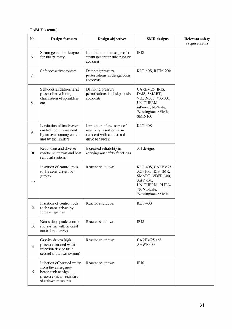
31
TABLE 3 (cont.)
No. Design features Design objectives SMR designs Relevant safety
requirements
6. Steam generator designed for full primary
Limitation of the scope of a steam generator tube rupture
accident
IRIS
7.
Soft pressurizer system Damping pressure
perturbations in design basis
accidents
KLT-40S, RITM-200
8.
Self-pressurization, large
pressurizer volume,
elimination of sprinklers,
etc.
Damping pressure
perturbations in design basis
accidents
CAREM25, IRIS,
DMS, SMART,
VBER-300, VK-300,
UNITHERM,
mPower, NuScale,
Westinghouse SMR,
SMR-160
9.
Limitation of inadvertent
control rod movement by an overrunning clutch
and by the limiters
Limitation of the scope of
reactivity insertion in an accident with control rod
drive bar break
KLT-40S
10.
Redundant and diverse
reactor shutdown and heat
removal systems
Increased reliability in
carrying out safety functions
All designs
11.
Insertion of control rods
to the core, driven by
gravity
Reactor shutdown KLT-40S, CAREM25,
ACP100, IRIS, IMR,
SMART, VBER-300,
ABV-6M,
UNITHERM, RUTA-
70, NuScale,
Westinghouse SMR
12.
Insertion of control rods
to the core, driven by force of springs
Reactor shutdown KLT-40S
13.
Non-safety-grade control
rod system with internal
control rod drives
Reactor shutdown IRIS
14.
Gravity driven high
pressure borated water
injection device (as a
second shutdown system)
Reactor shutdown CAREM25 and
AHWR300
15.
Injection of borated water
from the emergency
boron tank at high
pressure (as an auxiliary
shutdown measure)
Reactor shutdown IRIS

32
TABLE 3 (cont.)
No. Design features Design objectives SMR designs Relevant safety
requirements
16.
Emergency injection system (with borated
water), actuated by
rupture disks
Reactor shutdown plus prevention of core uncovery
in LOCA
CAREM25
17.
Natural convection core
cooling in all modes
Passive heat removal CAREM25, AHWR-
300, DMS, IMR,
ABV-6M, VK-300,
UNITHERM,
ELENA, NuScale,
SMR-160
18.
Safety (relief) valves Protection of reactor vessel
from over pressurization
IRIS, CAREM25, it
should be available in
all designs
19.
Long term gravity make-
up system
Assures that the core remains
covered indefinitely following a LOCA
IRIS and ACP100
TABLE 4. DESIGN FEATURES OF WATER COOLED SMR DESIGNS CONTRIBUTING TO LEVEL 4 OF
DEFENCE IN DEPTH
TABLE 4 (cont.)
No. Design features Design objectives SMR designs Relevant safety
requirements
1.
Relatively low core
power density
Limitation or
postponement of core
melting
IRIS, CAREM25,
NuScale and mPower
IAEA Safety
Standards Series
Specific Safety Requirements No.
SSR–2/1 (Rev. 1),
Safety of Nuclear
Power Plants:
Design
Requirement 20,
Paragraph 4.11 (a
and e) and relevant
Paragraphs. [11]
2.
Low heat-up rate of fuel elements predicted
in a hypothetical event
of core uncovery,
owing to design
features
Prevention of core melting due to core
uncovery
CAREM25 and mPower
3.
Passive emergency
core cooling.
To provide adequate time
for accident control
KLT-40S, IRIS, Flexblue,
DMS, KLT-40S,
CAREM25, VVER-300,
VBER-300, AHWR300
Westinghouse SMR,
ACP100, SMART, VK-
300, NuScale UNITHERM, mPower,
SMR-160
4.
Passive system of
reactor vessel bottom
cooling
In-vessel retention of core
melt KLT-40S, CAREM25
and Flexblue
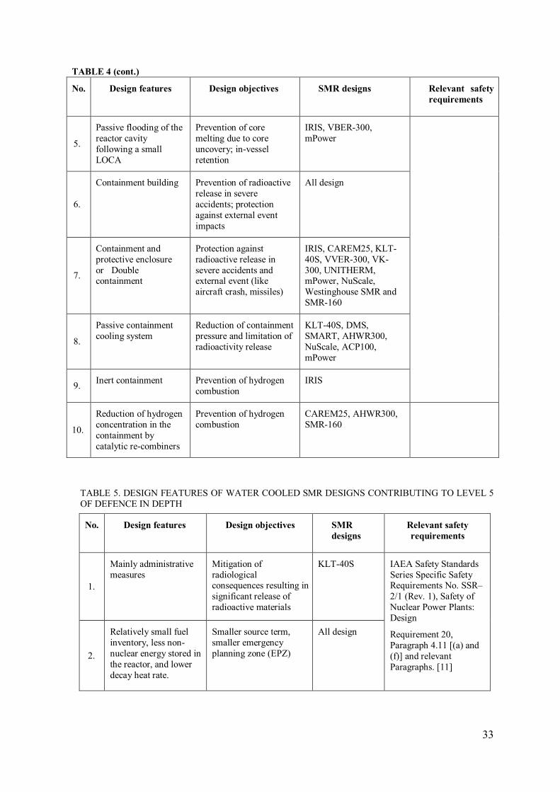
33
TABLE 4 (cont.)
No. Design features Design objectives SMR designs Relevant safety
requirements
5.
Passive flooding of the
reactor cavity
following a small
LOCA
Prevention of core
melting due to core
uncovery; in-vessel
retention
IRIS, VBER-300,
mPower
6.
Containment building Prevention of radioactive
release in severe
accidents; protection
against external event
impacts
All design
7.
Containment and
protective enclosure
or Double containment
Protection against
radioactive release in
severe accidents and external event (like
aircraft crash, missiles)
IRIS, CAREM25, KLT-
40S, VVER-300, VK-
300, UNITHERM, mPower, NuScale,
Westinghouse SMR and
SMR-160
8.
Passive containment
cooling system
Reduction of containment
pressure and limitation of
radioactivity release
KLT-40S, DMS,
SMART, AHWR300,
NuScale, ACP100,
mPower
9. Inert containment Prevention of hydrogen
combustion
IRIS
10.
Reduction of hydrogen
concentration in the
containment by
catalytic re-combiners
Prevention of hydrogen
combustion
CAREM25, AHWR300,
SMR-160
TABLE 5. DESIGN FEATURES OF WATER COOLED SMR DESIGNS CONTRIBUTING TO LEVEL 5
OF DEFENCE IN DEPTH
No. Design features Design objectives SMR
designs
Relevant safety
requirements
1.
Mainly administrative
measures
Mitigation of
radiological consequences resulting in
significant release of
radioactive materials
KLT-40S IAEA Safety Standards
Series Specific Safety Requirements No. SSR–
2/1 (Rev. 1), Safety of
Nuclear Power Plants:
Design
Requirement 20,
Paragraph 4.11 [(a) and
(f)] and relevant
Paragraphs. [11]
2.
Relatively small fuel
inventory, less non-
nuclear energy stored in
the reactor, and lower
decay heat rate.
Smaller source term,
smaller emergency
planning zone (EPZ)
All design
34
4. COUNTERMEASURES TO ADDRESS THE LESSONS LEARNED FROM
THE FUKUSHIMA DAIICHI ACCIDENT IN THE DESIGN OF WATER
COOLED SMALL MODULAR REACTORS
A nuclear power plant (NPP) is constructed and deployed with the main objective to
provide reliable electrical power along with the assurance of safety. To guarantee the
safety, a plant must be equipped with sufficient capacity and capability of reliable systems
in order to deal with various operation modes such as normal operation, shutdown,
maintenance and abnormal conditions throughout its design life. Invariably redundant
safety systems and barriers are also used to protect the people and environment inside and
surrounding the plant and to bring the plant back to safe condition as quickly as possible
when unacceptable conditions occur. In addition, diversity is also implemented to avoid
functional failure due to either common cause or common mode. General intention of the
redundancy and diversity across the systems inside the plant is to ensure that the systems
will reliably respond against any deviation or abnormality as designed to prevent and
mitigate progression of incident/accident and protect the health and safety of people and
the environment.
The plant has numerous systems that shall function properly and reliably as designed.
There are interconnected structures, subsystems and components which could raise
concerns of complexity. A strategy is needed to organize the components and systems so
that their roles are well managed for their success. The safety strategy can be ensured with
DiD concept where actions and mitigations are divided into several layers of defence. Plant
design is then analyzed using deterministic and probabilistic methods to guarantee the
capability of the plant systems in dealing with various events during its lifetime.
According to the IAEA publication ‘Defence in Depth in Nuclear Safety, INSAG-10, a
Report by the International Nuclear Safety Advisory Group’, the DiD concept has two
principal strategies: first, to prevent accidents and second, if prevention fails, to limit their
potential consequences and prevent any accident progression detrimental to the health and
safety of people or environment. Usually DiD is structured in five (5) levels in which
should one level fail, the subsequent level comes to play to deal with the reactor conditions
and protects the overall system. The five levels of defence are [11]:
1. Prevention of abnormal operation and system failures;
2. Control of abnormal operation and detection of failures;
3. Control of accident within the design basis;
4. Control of severe plant conditions including prevention of accident progression
and mitigation of the consequences of severe accidents;
5. Mitigation of radiological consequences to protect people and environment
against significant releases of radioactive materials.
The first level of DiD is conservatism in the design, and high quality of construction and
operation. The second level of DiD is use of control, limiting and protection systems and
surveillance means. The third level of DiD are ESFs to cope with postulated designs basis
accidents, such as LOCA. The fourth level of DiD employs complementary measures for
accident managements to anticipate the unexpected severe excursions when the capabilities
of ESFs are exceeded. The fifth level of DiD are off-site emergency response actions. Each
level of DiD should be independent of the others and failure in one level should not impair
the functionality of other levels.

35
As explained in Section 2 on the accident sequence in Units 1, 2 and 3, the Fukushima
Daiichi accident has revealed many lessons in dealing with extreme natural hazards for a
site with multiple reactors. The accident progression, facts and traces discovered from the
fact-finding expert missions, indicated weaknesses in design, accident management and the
regulatory system. It is known that the Fukushima Daiichi complex design basis tsunami
was far less than what really happened on March 11, 2011. Although the tsunami basis was
re-evaluated in 2002 and an updated information such as the Jogan Tsunami was brought
into attention, it was neither thoroughly considered nor accurately estimated [12]. This lack
of contingency consideration for potential natural hazards led to cliff edge effects to the
reactor facilities in the complex during the early phase of the accident. The huge volume of
water that came with the tsunami exceeded the height of the protective wall and became a
common cause for multiple damages to the facilities. The damages stretched to several
functions concurrently such as the damage to oil tanks, the loss of ultimate heat sink, the
loss of emergency power supplies due to water flooding in the EDG rooms, and the
reduced site accessibility due to the littered stray objects due to tsunami flood.
Multiple impacts from the extreme natural hazards resulted in significant difficulties in
managing available resources to cope with the unsafe conditions. Damaged roads slowed
down many required actions to respond the emergency situation. Loss of electric power
forced the operators to work in darkness when trying to control the reactors. Multiple units
with shared resources also hindered the equipment availability to fulfil the simultaneous
needs. For example, when the fire engine was asked for by Unit 3 for emergency water
injection, it was being used to resolve the problem in Unit 1.
These are a few examples of the lessons learned from the Fukushima Daiichi accident.
There are many others which have been revealed and documented. Experts from various
organizations collected and identified as many as 94 individual lessons and
recommendations on Fukushima Daiichi Accident [13] to [16], which are grouped into
integrated lessons learned. These integrated lessons are categorized into 4 main areas as
follows:
A. Design and Siting (section 4.1)
1. Strengthen measures against extreme natural hazards and consequential effects
2. Consider issues concerning multiple reactor sites and multiple sites
3. Ensure off-site and on-site electricity supplies
4. Ensure robust measures for reactor core cooling and ultimate heat sink
5. Ensure design of safety-related structures, systems and components
6. Ensure measures for prevention and mitigation of hydrogen explosions
7. Enhance containment venting and filtering system
8. Ensure hardened instrumentation and cables for safety-related parameters and
monitoring equipment
9. Enhance robustness of spent fuel cooling
10. Use PSA effectively for risk assessment and management
B. Accident Management and on-site emergency preparedness and response (section 4.2)
1. Ensure on-site emergency response facilities, equipment and procedures

36
2. Enhance human resource, skill and capabilities
C. Off-site emergency preparedness and response (section 4.3)
1. Strengthen off-site infrastructure and capability
2. Strengthen national arrangements for emergency preparedness and response
3. Enhance interaction and communication with the international communities
D. Nuclear safety infrastructures (section 4.4)
1. Review and clarify regulatory and emergency response framework
2. Reinforce safety regulatory bodies and legal structures
3. Instill safety awareness and attitude
Some countermeasures were discussed in the technical meetings (see section 1.4) to
address the lessons learned from the Fukushima Daiichi event. Table 1 through 18
summarizes the result of the meetings and the level of Defence-in-Depth being addressed.
DESIGN AND SITING 4.1.
Strengthen measures against extreme natural hazards and consequential 4.1.1.
effects
Historically, extreme natural events that disrupted the operation of NPPs appeared in many
different forms such as strong earthquake, high tsunami wave, major flooding, sustained
high heat, very strong wind, etc. In some cases, historical occurrences of the event showed
a regular pattern, interval and a certain indicative trend of the magnitude with return
periods. Although there exists uncertainty, the magnitude of the event can be projected
based on historical data and its indicative trend. According to the site circumstances,
design needs evaluation to incorporate the impact of the extreme events that have occurred.
Extreme events do not necessarily take place only in a single form. They can be
combination of two or more events that come in sequence, thus providing challenges to the
reactor facilities. The events may be very closely related as in a cause-effect relation, e.g.
tsunami and major flood following a large undersea earthquake, but in some instances
different type of natural hazards may occur at the same time. Designers of reactors need to
gather historic evidence of the occurrence and strength of the extreme events to be counted
in their design or analysis of safety system. However, uncertainty remains large as nature
of the occurrence is complex and not completely understood so that the prediction of the
strength, location and timing of occurrence is a challenge. Putting a conservative
consideration, designers need to consider credible historical data of single events with
adequate design margins and probable simultaneous occurrence.
The combination of two or more natural hazards can result in unprecedented impacts to the
reactor facility. The Fukushima Daiichi accident which underwent large earthquake and
subsequent tsunami revealed several lessons for the design of future reactors. The
following are some of the SMR design guidelines based on the lessons learned:
• Earthquake exceeding the design basis did not cause any known significant damage.
It was revealed that when the large scale earthquake exceeding the design basis
occurred, the safety system of the Fukushima Daiichi reactors worked as planned. The
reactors tripped and the EDGs automatically functioned as expected to supply

37
electricity needed by the reactor emergency system. The reactor building had no
significant damage and all safety equipment remained intact. This condition shows
that the design margin of the facilities was sufficient to withstand a larger earthquake.
This approach can be a guideline for SMR designs.
• Earthquake exceeding the design basis causing loss of off-site power source became
the initiating event for accident scenario.
Although the earthquake did not cause any significant challenge to the reactor
systems, it damaged the infrastructure of electrical grid connected to the station. This
led to a loss of off-site power source which became the initiating event for accident
that occurred. As designed, loss of off-site power automatically activated the EDGs to
supply reactor safety system with electrical power. However, the failure of EDGs after
the tsunami induced flooding lead to common cause/common mode failures of all
EDGs. A total blackout in the complex resulted in a total loss of emergency core
cooling as the DC power was also lost after some time when the batteries drained
below their limits. Debris from tsunami and hydrogen explosion created significant
logistical difficulties and inhibited response actions. Tsunami spread wreckages and
debris on roads and at gates and some areas remained flooded for a long time.
Hydrogen explosions damaged the buildings significantly and spread contamination
into atmosphere. The debris delayed the arrival of fire engine and emergency teams at
the complex and limited the field working time as the radioactivity level rose up
rapidly after the explosion. SMR design guidelines should consider some
independence, during a practical grace period, e.g. from off-site power, availability of
cooling sources, communication and transportation systems, etc.
• Optimizing for earthquake made some equipment vulnerable to tsunami (e.g., locating
EDGs underground).
When a strong earthquake shook the Fukushima Daiichi reactor complex, the EDG
buildings did not lose their integrity. The buildings were designed and placed
conservatively underground to provide better resilience against the earthquake
hazards, but this location resulted in their flooding when the tsunami exceeded the
height of the protection wall. SMR design should accommodate combined effects of
various natural hazards.
• Extensive tsunami and subsequent hydrogen explosion damage and debris created
significant logistical difficulties and inhibited response actions.
The large high tsunami waves created much more damages to the site and reactor
facilities than the earthquake. The tsunami spread wreckages and debris on the roads
and at gates. Some areas remained flooded for a long time. In addition, hydrogen
explosions damaged the buildings significantly and spread contamination to the
atmosphere. The debris delayed the arrival of fire engine and emergency teams at the
complex and hampered the efforts to control the reactor by the emergency team such
as delaying the delivery of a fire engine to the complex and limiting the field working
time as the radioactivity level rose up rapidly after the explosion.
• Repeated aftershocks and tsunami threats stopped recovery work on occasions.
During emergency recovery the workers efforts were interrupted and they had to take
shelter due to repeated tremors. This caused further delays in providing immediate
alternate cooling for the reactor leading to more extensive fuel damage.
38
SMR design should consider subsequent effects of natural hazards that could be
beyond the first occurrence.
All the findings from the Fukushima Daiichi accident need to be addressed. The accident
basically confirmed the necessity of strengthening measures against extreme natural
hazards and their consequential effects. SMRs, which have variety of site options, should
carefully include them in the design considerations as they may be deployed in sites such
as coastal areas, islands, on floating barges, underground, and near high population zones.
Following TABLE 6 summarises the strengthening measures against natural hazards and
consequential effects.
Applicable Safety Requirements against extreme natural hazards and consequential
effects [11]
Requirement 17 of SSR–2/1 (Rev. 1) establishes the following requirements on internal
and external hazards.
“All foreseeable internal hazards and external hazards, including the potential for
human induced events directly or indirectly to affect the safety of the NPP, shall be
identified and their effects shall be evaluated. Hazards shall be considered in designing
the layout of the plant and in determining the postulated initiating events and generated
loadings for use in the design of relevant items important to safety for the plant”.
Paragraph 5.17 requires that the design shall include due consideration of those natural
and human induced external events (i.e. events of origin external to the plant) that have
been identified in the site evaluation process. Causation and likelihood shall be
considered in postulating potential hazards. In the short term, the safety of the plant
shall not be permitted to be dependent on the availability of off-site services such as
electricity supply and fire-fighting services. The design shall take due account of site
specific conditions to determine the maximum delay time by which off-site services
need to be available.
Paragraph 5.19 requires that features shall be provided to minimize any interactions
between buildings containing items important to safety (including power cabling and
control cabling) and any other plant structure as a result of external events considered in
the design.
Paragraph 5.21 requires that the design of the plant shall provide for an adequate
margin to protect items important to safety against levels of external hazards to be
considered for design seismic events taking into account the site hazard evaluation, and
to avoid cliff edge effects.
Paragraph 5.21a requires that the design of the plant shall provide for an adequate
margin to protect items ultimately necessary to prevent large or early radioactive
releases in the event of levels of natural hazards exceeding those to be considered for
design taking into account the site hazard evaluation.

39
TABLE 6. STRENGTHENING MEASURES AGAINST EXTREME NATURAL HAZARDS AND
CONSEQUENTIAL EFFECTS
TABLE 6 (cont.)
Defence in
Depth level
Critical
issues
addressed
Option for
counter-
measures
Considerations for water cooled SMRs
Relevant
safety
requirements
Prevention
(1)
Natural
hazards
Ensure that all
types of natural
hazards are
considered in the
design.
• Natural hazards include earthquake,
tsunami, external flood, high winds
(typhoon, cyclone, hurricane and tornado),
forest fire, snow, ice storm, extreme cold
weather, dam break, volcano, and sand
storm.
• The set and magnitude of natural phenomena should be specific to the site.
The criteria should include return cycle of
the worst event which can be common to
all SMR sites in that area.
• Entire available history (paleo-science)
should be taken into consideration.
IAEA Safety
Standards
Series Specific
Safety
Requirements
No. SSR–2/1
(Rev. 1), Safety of
Nuclear Power
Plants: Design
Requirement
17 and
relevant
Paragraphs.
[11] Prevention
(1)
Magnitude of
hazards
Ensure that
trends and
uncertainties are
considered in
determining the magnitude of
natural
phenomena
which should be
mitigated.
• The type and cause of natural hazards is
site specific but it is better to consider
large margin (highest in the region)
depending on the site characteristics of the
plant.
• The magnitude should be predicted for a
return cycle corresponding to the core
damage frequency goal considering trends
and uncertainties.
Prevention
(1)
Design
adequacy
Confirm design
adequacy of
structures and
components to
stand against
natural hazards.
• Seismic adequacy of SSCs which provide
reactor shutdown, core cooling and decay
heat removal, especially RPV integrity, is
most important.
• Usually SMRs have a small footprint for
the containment and reactor building.
Some SMRs adopt the seismic isolation option. In the case of re-evaluation of the
seismic grade of the site (see NRC
recommendation [15]), to some extent the
isolators could be redesigned and
substituted to allow more flexibility and to
upgrade the seismic resistance of the
containment and reactor building.
Prevention
(1)
Siting,
location
Confirm that the
choice of the
site takes into
account all
probable natural hazards along
with
consequential
cascade effects.
• The magnitude and return cycle should
consider nearby dams and water sources
failing in the worst manner.
• Evaluate the system for more flooding from earthen dam breaks.
• For a plant with air-cooled ultimate heat
sink, the effect of flooding on the air
cooling tower should be considered.
• In case of underground site (positive
solution for seismic), water tightness of
safety critical structures, systems and
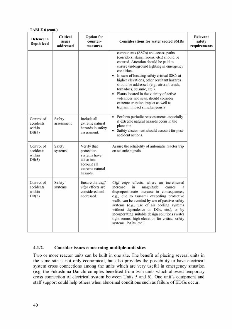
40
TABLE 6 (cont.)
Defence in
Depth level
Critical
issues
addressed
Option for
counter-
measures
Considerations for water cooled SMRs
Relevant
safety
requirements
components (SSCs) and access paths
(corridors, stairs, rooms, etc.) should be
ensured. Attention should be paid to
ensure underground lighting in emergency
condition.
• In case of locating safety critical SSCs at
higher elevations, other resultant hazards
should be addressed (e.g., aircraft crash,
tornadoes, seismic, etc.).
• Plants located in the vicinity of active
volcanoes and seas, should consider
extreme eruption impact as well as
tsunami impact simultaneously.
Control of
accidents
within
DB(3)
Safety
assessment
Include all
extreme natural
hazards in safety
assessment.
• Perform periodic reassessments especially
if extreme natural hazards occur in the
plant site.
• Safety assessment should account for post-
accident actions.
Control of
accidents
within DB(3)
Safety
systems
Verify that
protection
systems have taken into
account all
extreme natural
hazards.
Assure the reliability of automatic reactor trip
on seismic signals.
Control of
accidents
within
DB(3)
Safety
systems
Ensure that cliff
edge effects are
considered and
addressed.
Cliff edge effects, where an incremental
increase in magnitude causes a
disproportionate increase in consequences,
e.g., due to tsunami exceeding protective
walls, can be avoided by use of passive safety
systems (e.g., use of air cooling systems
without dependence on DGs, etc.), or by
incorporating suitable design solutions (water tight rooms, high elevation for critical safety
systems, PARs, etc.).
Consider issues concerning multiple-unit sites 4.1.2.
Two or more reactor units can be built in one site. The benefit of placing several units in
the same site is not only economical, but also provides the possibility to have electrical
system cross connections among the units which are very useful in emergency situation
(e.g. the Fukushima Daiichi complex benefited from twin units which allowed temporary
cross connection of electrical system between Units 5 and 6). One unit’s equipment and
staff support could help others when abnormal conditions such as failure of EDGs occur.
41
However, a site with several units also faces potential major problems. The Fukushima
Daiichi accident indicated that multiple reactor units in one site face the followings:
• Unexpected problems
Hydrogen gas produced in Unit 3 due to the interaction of melting core and steam
leaked to Unit 4 through shared venting system between the two units. The hydrogen
then detonated in Unit 4, damaged the reactor building and distracted the emergency
team in dealing with the Unit 1. Such an explosion was never foreseen. The explosion
in Unit 4 influenced the emergency team to concentrate more on Unit 4 spent fuel
pool, wrongly perceiving that the source of hydrogen explosion was due to uncovered
fuel in the spent fuel pool.
• Unexpected aftershock challenges
When multiple reactors are built at a site, unexpected challenges can happen as an
accident in one unit may disrupt the operation and accident management of the
neighboring reactors. In the Fukushima Daiichi accident when the emergency team
was trying to cope with the situation in Units 1 and 2, the explosion in Unit 1 spread
radioactive debris in the area around the complex. The explosion damaged the cables
and mobile generators that had been installed to provide power to the standby liquid
control pumps. The emergency teams had to work in challenging circumstances. They
faced a mix of problems from stabilizing the reactor systems to protecting themselves
from the radiation due to explosion in other units. The workers had to wear additional
protective clothing and stay within time limitations thus limiting their mobility and
availability.
• The need to respond to all units concurrently strained all resources on-site
In multiple-units sites, there is a possibility that several reactors undergo concurrent
accidents due to a common cause. When these simultaneous accidents occur, the
resources to handle all abnormal conditions at the same time become strained. For
example, when operators of Unit 3 requested a fire engine to be dispatched to prepare
water injection, all of the site fire engines were being used to mitigate the ongoing
problem in Unit 1. Earlier, requests for off-site fire engines were unsuccessful because
the roads were impassable.
As the above findings reveal, it is recognized that the issues concerning multiple reactor
sites and multiple sites must be addressed. The current design of SMRs typically offers
multiple reactor modules in one plant which ranges from two (2) to twelve (12) modules.
So it is important to consider the issues of countermeasures shown in the TABLE 7.
Applicable Safety Requirements concerning multiple-unit sites [11]
Requirement 33 of SSR–2/1 (Rev. 1) establishes the following requirements on safety
systems, and safety features for design extension conditions, of units of a multiple unit
nuclear power plant.
“Each unit of a multiple unit nuclear power plant shall have its own safety systems and
shall have its own safety features for design extension conditions”.
Paragraph 5.63 requires that means allowing interconnections between units of a
multiple unit nuclear power plant shall be considered in the design to further enhance
safety.
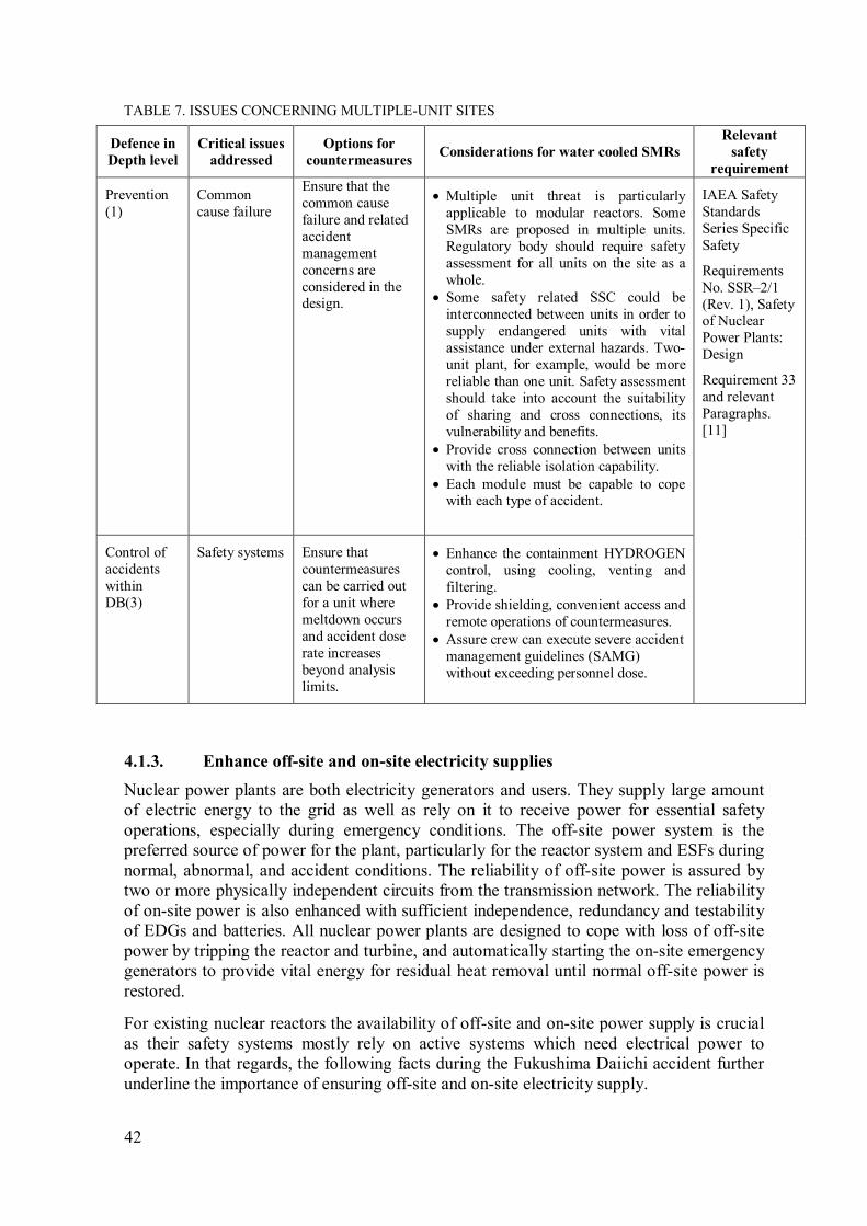
42
TABLE 7. ISSUES CONCERNING MULTIPLE-UNIT SITES
Defence in
Depth level
Critical issues
addressed
Options for
countermeasures Considerations for water cooled SMRs
Relevant
safety
requirement
Prevention
(1)
Common
cause failure
Ensure that the
common cause
failure and related
accident
management
concerns are
considered in the design.
• Multiple unit threat is particularly
applicable to modular reactors. Some
SMRs are proposed in multiple units.
Regulatory body should require safety
assessment for all units on the site as a
whole.
• Some safety related SSC could be
interconnected between units in order to
supply endangered units with vital
assistance under external hazards. Two-
unit plant, for example, would be more
reliable than one unit. Safety assessment
should take into account the suitability
of sharing and cross connections, its
vulnerability and benefits.
• Provide cross connection between units
with the reliable isolation capability.
• Each module must be capable to cope with each type of accident.
IAEA Safety
Standards
Series Specific
Safety
Requirements
No. SSR–2/1
(Rev. 1), Safety of Nuclear
Power Plants:
Design
Requirement 33
and relevant
Paragraphs.
[11]
Control of
accidents
within
DB(3)
Safety systems Ensure that
countermeasures
can be carried out
for a unit where
meltdown occurs
and accident dose
rate increases
beyond analysis
limits.
• Enhance the containment HYDROGEN
control, using cooling, venting and
filtering.
• Provide shielding, convenient access and
remote operations of countermeasures.
• Assure crew can execute severe accident
management guidelines (SAMG)
without exceeding personnel dose.
Enhance off-site and on-site electricity supplies 4.1.3.
Nuclear power plants are both electricity generators and users. They supply large amount
of electric energy to the grid as well as rely on it to receive power for essential safety
operations, especially during emergency conditions. The off-site power system is the
preferred source of power for the plant, particularly for the reactor system and ESFs during
normal, abnormal, and accident conditions. The reliability of off-site power is assured by
two or more physically independent circuits from the transmission network. The reliability
of on-site power is also enhanced with sufficient independence, redundancy and testability
of EDGs and batteries. All nuclear power plants are designed to cope with loss of off-site
power by tripping the reactor and turbine, and automatically starting the on-site emergency
generators to provide vital energy for residual heat removal until normal off-site power is
restored.
For existing nuclear reactors the availability of off-site and on-site power supply is crucial
as their safety systems mostly rely on active systems which need electrical power to
operate. In that regards, the following facts during the Fukushima Daiichi accident further
underline the importance of ensuring off-site and on-site electricity supply.

43
• All EDGs started as designed after off-site power loss caused by earthquake.
However, they did not operate for long. When the tsunami hit the complex, seawater
filled the DG building and all generators in the operating units were crippled beyond
reasonable recovery.
• Elevation of switchboards was low in the building with little margin for flooding. This
contributed adversely to the consequence of the accident. A submerged switchboard
made electricity power recovery impossible for a long time. Before the Fukushima
Daiichi nuclear accident, a complete loss of all switchboards for an extended period
was not sufficiently considered. A complete loss of DC power was not addressed
either. This made the duration of station blackout (SBO) unpredictable prior to the
event.
• It was discovered that a signal generated by loss of all DC power caused IC valves to
close on LOCA signal and disabled the passive core cooling system. This shows the
important role of DC power in ensuring the establishment of passive system, and that
this was essential for the Fukushima Daiichi nuclear plants.
• SMR designers should consider DC power unavailability and ensure core cooling and
decay heat removal.
Reliance on active systems for safety functions has been greatly reduced in SMRs designs.
Passive cooling systems with a long grace period for DBAs provide improvement over
existing reactor designs. However, attention should be paid to the supply of power,
especially for severe accident management where the lighting and monitoring systems are
needed to cope with the situation.
In order to deal with the above facts, some options of countermeasures to enhance off-site
and on-site power are described in TABLE 8.
Applicable Safety Requirements on off-site and on-site electricity supplies [11]
Requirement 68 of SSR–2/1 (Rev. 1) establishes the following requirements on design
for withstanding the loss of off-site power
“The design of a nuclear power plant shall include an emergency power supply capable
of supplying the necessary power in anticipated operational occurrences and design
basis accidents, in the event of the loss of off-site power. The design shall include an
alternate power source to supply the necessary power in design extension conditions”.
Paragraph 6.43 requires that the design specifications for the emergency power supply
and for the alternate power source at the nuclear power plant due the requirements for
capability, availability, duration of the required power supply, capacity and continuity.
Paragraph 6.44 requires that the combined means to provide emergency power (such as
water, steam or gas turbines, diesel engines or batteries) shall have a reliability and type
that are consistent with all the requirements of the safety systems to be supplied with
power, and their functional capability shall be testable.
Paragraph 6.44a requires that the alternate power source shall be capable of supplying
the necessary power to preserve the integrity of the reactor coolant system and to
prevent significant damage to the core and to spent fuel in the event of the loss of off-
site power combined with failure of the emergency power supply.
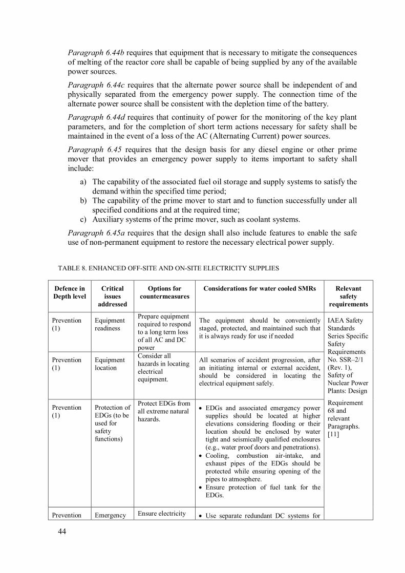
44
Paragraph 6.44b requires that equipment that is necessary to mitigate the consequences
of melting of the reactor core shall be capable of being supplied by any of the available
power sources.
Paragraph 6.44c requires that the alternate power source shall be independent of and
physically separated from the emergency power supply. The connection time of the
alternate power source shall be consistent with the depletion time of the battery.
Paragraph 6.44d requires that continuity of power for the monitoring of the key plant
parameters, and for the completion of short term actions necessary for safety shall be
maintained in the event of a loss of the AC (Alternating Current) power sources.
Paragraph 6.45 requires that the design basis for any diesel engine or other prime
mover that provides an emergency power supply to items important to safety shall
include:
a) The capability of the associated fuel oil storage and supply systems to satisfy the
demand within the specified time period;
b) The capability of the prime mover to start and to function successfully under all
specified conditions and at the required time;
c) Auxiliary systems of the prime mover, such as coolant systems.
Paragraph 6.45a requires that the design shall also include features to enable the safe
use of non-permanent equipment to restore the necessary electrical power supply.
TABLE 8. ENHANCED OFF-SITE AND ON-SITE ELECTRICITY SUPPLIES
TABLE 8 (cont.)
Defence in
Depth level
Critical
issues
addressed
Options for
countermeasures
Considerations for water cooled SMRs Relevant
safety
requirements
Prevention
(1)
Equipment
readiness
Prepare equipment
required to respond
to a long term loss
of all AC and DC
power
The equipment should be conveniently
staged, protected, and maintained such that
it is always ready for use if needed
IAEA Safety
Standards
Series Specific
Safety
Requirements
No. SSR–2/1
(Rev. 1), Safety of
Nuclear Power
Plants: Design
Requirement
68 and
relevant
Paragraphs.
[11]
Prevention
(1)
Equipment
location
Consider all
hazards in locating
electrical equipment.
All scenarios of accident progression, after
an initiating internal or external accident,
should be considered in locating the electrical equipment safely.
Prevention
(1)
Protection of
EDGs (to be
used for
safety
functions)
Protect EDGs from
all extreme natural
hazards.
• EDGs and associated emergency power
supplies should be located at higher
elevations considering flooding or their
location should be enclosed by water
tight and seismically qualified enclosures
(e.g., water proof doors and penetrations).
• Cooling, combustion air-intake, and
exhaust pipes of the EDGs should be
protected while ensuring opening of the
pipes to atmosphere.
• Ensure protection of fuel tank for the
EDGs.
Prevention Emergency Ensure electricity • Use separate redundant DC systems for

45
TABLE 8 (cont.)
Defence in
Depth level
Critical
issues
addressed
Options for
countermeasures
Considerations for water cooled SMRs Relevant
safety
requirements
(1) power
supplies
supplies for safety
systems.
various safety functions, e.g., for reactor
safety monitoring instruments, power
system actuation, valves and motors
motive power, etc., with complete
electrical and physical separation.
• Provide diverse DC power sources (such
as diesel driven DC generators) [17].
• Use diversity in power sources
functionality (e.g., water cooled EDGs as well as air-cooled EDGs) [17].
• In addition portable generators and
batteries should be considered for
extreme situations, if those proposed
above fail inadvertently.
Mitigation
of severe
accident (4)
Complete
Power
recovery
Ensure quick
recovery processes
for all power
supplies during
severe accidents.
Perform analysis to reduce the time to
restore off-site and on-site supplies after
their loss in severe accidents (e.g., by means
of design provisions, administrative actions,
and their combination thereof).
Prevention (1)
Switch-boards
Ensure that the switchboards
availability is
maintained during
all extreme events.
Provide sealed compartments to secure components and power panels in case of
flooding [17].
Control of
accidents
within
DB(3)
Electricity
supply
Ensure that
operator action and
electricity supply
are not needed
during grace
period.
• Usually SMRs rely more on passive
safety features to the extent possible, thus
on-site and off-site electricity may not be
needed for the grace period. DGs could
be avoided, at least as safety systems.
• The assurance of a suitable grace period
(without need of intervention from operators and need of electricity supplies)
should be duly considered.
Control of
accidents
within DB
(3)
Electricity
supply
Ensure reliability
of valves in passive
system.
Provide combination of manual and
electrically driven valves for safety
functions as well as fail-to-safe features.
Control of
accidents
within DB
(3)
Electricity
supply
Maximize
survivability of AC
and DC systems
and components
[17].
• Provide manual AC and DC cross
connection capability between adjacent
units [18].
• Provide access and connections for
prestaged power sources [18].

46
Ensure robust measures for reactor core cooling and ultimate heat sinks 4.1.4.
Continuous core cooling is crucial in water cooled reactors during normal operation,
shutdown conditions and in emergency situations. In normal operation it transfers the core
thermal power from the fuel cladding and uses it to generate steam. When the reactor is
shut down the core decay heat should be removed to maintain the fuel clad temperature
below acceptable limits. During DBAs, e.g. LOCA, emergency core cooling must be
provided to prevent core degradation by maintaining the fuel cladding temperature below
its melting point. Integrity of fuel clad ensures that the radioactive fission products remain
within the first barrier which is the foremost and the fundamental safety requirement. Due
to this, a robust design of core cooling systems is essential.
In the early phase of the Fukushima Daiichi accident, loss of off-site power did not
interrupt the core cooling systems and they worked as designed with the power supplied by
EDGs. Later however, the EDGs were crippled by tsunami and the successive cooling
systems degraded and failed. In Unit 1 the indicators in the control room for IC failed. In
Units 2 and 3, the steam-driven systems, namely, RCIC and HPCI kept working for a few
days. A loss of core cooling systems and failure to provide core cooling by other means
lead to severe core damage. Based on these lessons, the following TABLE 9 recommends
options for the countermeasures.
Applicable Safety Requirements for reactor core cooling and ultimate heat sinks [11]
Requirement 47 of SSR–2/1 (Rev. 1) establishes the following requirements on design of
reactor coolant systems
“The components of the reactor coolant systems for the nuclear power plant shall be
designed and constructed so that the risk of faults due to inadequate quality of materials,
inadequate design standards, insufficient capability for inspection or inadequate quality
of manufacture is minimized”.
Paragraph 6.13 requires that pipework connected to the pressure boundary of the
reactor coolant systems for the nuclear power plant shall be equipped with adequate
isolation devices to limit any loss of radioactive fluid (primary coolant) and to prevent
the loss of coolant through interfacing systems.
Paragraph 6.14 requires that the design of the reactor coolant pressure boundary shall
be such that flaws are very unlikely to be initiated, and any flaws that are initiated
would propagate in a regime of high resistance to unstable fracture and to rapid crack
propagation, thereby permitting the timely detection of flaws.
Paragraph 6.15 requires that the design of the reactor coolant systems shall be such as
to ensure that plant states in which components of the reactor coolant pressure boundary
could exhibit embrittlement are avoided.
Paragraph 6.16 requires that the design of the components contained inside the reactor
coolant pressure boundary, such as pump impellers and valve parts, shall be such as to
minimize the likelihood of failure and consequential damage to other components of the
primary coolant system that are important to safety, in all operational states and in
design basis accident conditions, with due allowance made for deterioration that might
occur in service.
Requirement 51 establishes the following requirements on removal of residual heat
from the reactor core
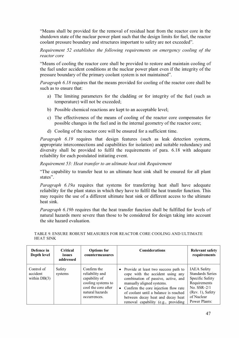
47
“Means shall be provided for the removal of residual heat from the reactor core in the
shutdown state of the nuclear power plant such that the design limits for fuel, the reactor
coolant pressure boundary and structures important to safety are not exceeded”.
Requirement 52 establishes the following requirements on emergency cooling of the
reactor core
“Means of cooling the reactor core shall be provided to restore and maintain cooling of
the fuel under accident conditions at the nuclear power plant even if the integrity of the
pressure boundary of the primary coolant system is not maintained”.
Paragraph 6.18 requires that the means provided for cooling of the reactor core shall be
such as to ensure that:
a) The limiting parameters for the cladding or for integrity of the fuel (such as
temperature) will not be exceeded;
b) Possible chemical reactions are kept to an acceptable level;
c) The effectiveness of the means of cooling of the reactor core compensates for
possible changes in the fuel and in the internal geometry of the reactor core;
d) Cooling of the reactor core will be ensured for a sufficient time.
Paragraph 6.19 requires that design features (such as leak detection systems,
appropriate interconnections and capabilities for isolation) and suitable redundancy and
diversity shall be provided to fulfil the requirements of para. 6.18 with adequate
reliability for each postulated initiating event.
Requirement 53: Heat transfer to an ultimate heat sink Requirement
“The capability to transfer heat to an ultimate heat sink shall be ensured for all plant
states”.
Paragraph 6.19a requires that systems for transferring heat shall have adequate
reliability for the plant states in which they have to fulfil the heat transfer function. This
may require the use of a different ultimate heat sink or different access to the ultimate
heat sink.
Paragraph 6.19b requires that the heat transfer function shall be fulfilled for levels of
natural hazards more severe than those to be considered for design taking into account
the site hazard evaluation.
TABLE 9. ENSURE ROBUST MEASURES FOR REACTOR CORE COOLING AND ULTIMATE
HEAT SINK
TABLE 9 (cont.)
Defence in
Depth level
Critical
issues
addressed
Options for
countermeasures
Considerations Relevant safety
requirements
Control of
accident
within DB(3)
Safety
systems
Confirm the
reliability and
capability of
cooling systems to
cool the core after
natural hazards
occurrences.
• Provide at least two success path to
cope with the accident using any
combination of passive, active, and
manually aligned systems.
• Confirm the core injection flow rate
of coolant until a balance is reached
between decay heat and decay heat
removal capability (e.g., providing
IAEA Safety
Standards Series
Specific Safety
Requirements
No. SSR–2/1
(Rev. 1), Safety
of Nuclear
Power Plants:
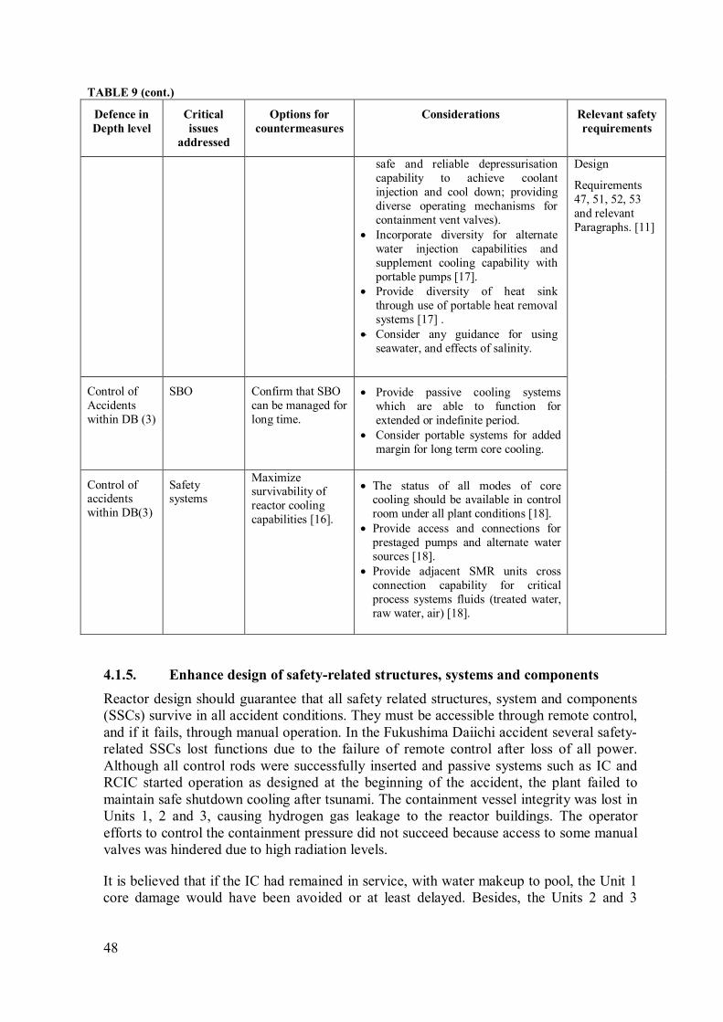
48
TABLE 9 (cont.)
Defence in
Depth level
Critical
issues
addressed
Options for
countermeasures
Considerations Relevant safety
requirements
safe and reliable depressurisation
capability to achieve coolant
injection and cool down; providing
diverse operating mechanisms for
containment vent valves).
• Incorporate diversity for alternate
water injection capabilities and
supplement cooling capability with
portable pumps [17].
• Provide diversity of heat sink
through use of portable heat removal
systems [17] .
• Consider any guidance for using
seawater, and effects of salinity.
Design
Requirements
47, 51, 52, 53
and relevant
Paragraphs. [11]
Control of
Accidents
within DB (3)
SBO Confirm that SBO
can be managed for
long time.
• Provide passive cooling systems
which are able to function for
extended or indefinite period.
• Consider portable systems for added
margin for long term core cooling.
Control of accidents
within DB(3)
Safety systems
Maximize survivability of
reactor cooling
capabilities [16].
• The status of all modes of core cooling should be available in control
room under all plant conditions [18].
• Provide access and connections for
prestaged pumps and alternate water
sources [18].
• Provide adjacent SMR units cross
connection capability for critical
process systems fluids (treated water,
raw water, air) [18].
Enhance design of safety-related structures, systems and components 4.1.5.
Reactor design should guarantee that all safety related structures, system and components
(SSCs) survive in all accident conditions. They must be accessible through remote control,
and if it fails, through manual operation. In the Fukushima Daiichi accident several safety-
related SSCs lost functions due to the failure of remote control after loss of all power.
Although all control rods were successfully inserted and passive systems such as IC and
RCIC started operation as designed at the beginning of the accident, the plant failed to
maintain safe shutdown cooling after tsunami. The containment vessel integrity was lost in
Units 1, 2 and 3, causing hydrogen gas leakage to the reactor buildings. The operator
efforts to control the containment pressure did not succeed because access to some manual
valves was hindered due to high radiation levels.
It is believed that if the IC had remained in service, with water makeup to pool, the Unit 1
core damage would have been avoided or at least delayed. Besides, the Units 2 and 3

49
needed implementation of feed and bleed cooling to avoid core damage but the effort was
limited by lack of water supply and power to steam driven pump.
In SMRs such failures of safety related structures, systems and components should be
prevented or accommodated with compensatory measures. The following TABLE 10
explains some considerations.
Applicable Safety Requirements for safety-related structures, systems and
components [11]
Requirement 45 of SSR–2/1 (Rev. 1) establishes the following requirements on control
of the reactor core.
“Distributions of neutron flux that can arise in any state of the reactor core in the
nuclear power plant, including states arising after shutdown and during or after
refuelling, and states arising from anticipated operational occurrences and from accident
conditions not involving degradation of the reactor core, shall be inherently stable. The
demands made on the control system for maintaining the shapes, levels and stability of
the neutron flux within specified design limits in all operational states shall be
minimized”.
Requirement 46 establishes the following requirements on reactor shutdown.
“Means shall be provided to ensure that there is a capability to shut down the reactor of
the nuclear power plant in operational states and in accident conditions, and that the
shutdown condition can be maintained even for the most reactive conditions of the
reactor core”.
Requirement 48 establishes the following requirements on overpressure protection of
the reactor coolant pressure boundary.
“Provision shall be made to ensure that the operation of pressure relief devices will
protect the pressure boundary of the reactor coolant systems against overpressure and
will not lead to the release of radioactive material from the nuclear power plant directly
to the environment”.
Requirement 49 establishes the following requirements on inventory of reactor coolant.
“Provision shall be made for controlling the inventory, temperature and pressure of the
reactor coolant to ensure that specified design limits are not exceeded in any operational
state of the nuclear power plant, with due account taken of volumetric changes and
leakage”.
Requirement 55 establishes the following requirements on control of radioactive
releases from the containment.
“The design of the containment shall be such as to ensure that any release of radioactive
material from the nuclear power plant to the environment is as low as reasonably
achievable, is below the authorized limits on discharges in operational states and is
below acceptable limits in accident conditions”.
Requirement 58 establishes the following requirements on control of containment
conditions.
“Provision shall be made to control the pressure and temperature in the containment at a
nuclear power plant and to control any build-up of fission products or other gaseous,
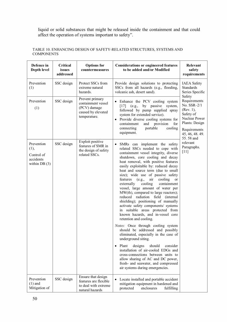
50
liquid or solid substances that might be released inside the containment and that could
affect the operation of systems important to safety”.
TABLE 10. ENHANCING DESIGN OF SAFETY-RELATED STRUCTURES, SYSTEMS AND
COMPONENTS
TABLE 10 (cont.)
Defence in
Depth level
Critical
issues
addressed
Options for
countermeasures
Considerations or engineered features
to be added and/or Modified
Relevant
safety
requirements
Prevention (1)
SSC design Protect SSCs from extreme natural
hazards.
Provide design solutions to protecting SSCs from all hazards (e.g., flooding,
volcanic ash, desert sand).
IAEA Safety Standards
Series Specific
Safety
Requirements
No. SSR–2/1
(Rev. 1),
Safety of
Nuclear Power
Plants: Design
Requirements
45, 46, 48. 49. 55. 58 and
relevant
Paragraphs.
[11]
Prevention
(1)
SSC design Prevent primary
containment vessel
(PCV) damage
caused by elevated
temperature.
• Enhance the PCV cooling system
[17] (e.g., by passive system,
followed by pump supplied spray
system for extended service).
• Provide diverse cooling systems for
containment and provision for
connecting portable cooling
equipment.
Prevention
(1),
Control of
accidents
within DB (3)
SSC design Exploit positive
features of SMR in the design of safety
related SSCs.
• SMRs can implement the safety
related SSCs needed to cope with containment vessel integrity, diverse
shutdown, core cooling and decay
heat removal, with positive features
easily exploitable by: reduced decay
heat and source term (due to small
size); wide use of passive safety
features (e.g., air cooling or
externally cooling containment
vessel, large amount of water per
MW(th), compared to large reactors);
reduced radiation field (internal shielding); positioning of manually
activate safety components/ systems
in suitable areas protected from
known hazards, and in-vessel core
retention and cooling.
Notes: Once through cooling system
should be addressed and possibly
eliminated, especially in the case of
underground siting.
• Plant designs should consider
installation of air-cooled EDGs and
cross-connections between units to allow sharing of AC and DC power,
fresh- and seawater, and compressed
air systems during emergencies.
Prevention
(1) and
Mitigation of
SSC design Ensure that design
features are flexible
to deal with extreme
natural hazards
• Locate installed and portable accident
mitigation equipment in hardened and
protected enclosures fulfilling

51
TABLE 10 (cont.)
Defence in
Depth level
Critical
issues
addressed
Options for
countermeasures
Considerations or engineered features
to be added and/or Modified
Relevant
safety
requirements
severe
accident (4)
including fires, as
well as man-made
threats (sabotage or
terror).
applicable safety requirements.
• Portable equipment storage should be
off-site, far enough to avoid exposure
to the on-site hazards, with
transportation plans in place.
Control of
accidents
within DB(3)
Redundancy Ensure that the
design covers cases
where the primary
coping system/function
fails. This should be
the case for all
scenarios.
The design should not depend on any
single active or passive system or
function. The redundant backup should
be diverse, such that if the primary system/function fails for some reason,
the backup system/function remains
available and it should not fail for the
same reason.
Prevention
(1) and
mitigation of
severe
accidents (4)
Connecting
ability
Ensure capability to
connect safety
related SSCs with
external equipment.
• Provide redundant exterior
"hardened" connections to supply
water to reactor with reliable/manual
venting for boil off (including de-
pressurizing of the reactor/ primary
system).
• Provide, normally isolated external manual connections manual to be
used by portable equipment for:
-Cooling and spraying
-Filtering and HYDROGEN
recombination
Prevention
(1) and
mitigation of
severe
accident (4)
Accessi-
bility
Ensure that safety
related SSC can be
accessed during
emergencies.
• One of the lessons learned was that
the operators could not access the
containment vent valves to open
them, because the motor control
centre (MCC's) were flooded and
valves exceeded their design qualification conditions due to the
severe accident condition.
• Redundant and diverse
systems/equipment should be placed
exterior to the main buildings.
Shielded/remote-operated manual
mechanisms should be provided to
allow actuation in case of severe
accidents or extensive site damage, to
re-establish core cooling. Mechanical
remote operation may use hydraulic,
pneumatic, fluidic means instead of electrical power to allow more
reliable operation with diverse
function.
Control of
accidents
Safety Ensure that all of the
safety functions are • Survivability and reliability of
emergency power supply system
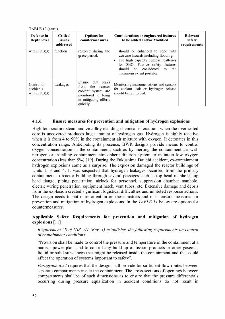
52
TABLE 10 (cont.)
Defence in
Depth level
Critical
issues
addressed
Options for
countermeasures
Considerations or engineered features
to be added and/or Modified
Relevant
safety
requirements
within DB(3) function restored during the
grace period.
should be enhanced to cope with
extreme hazards including flooding.
• Use high capacity compact batteries
for SBO. Passive safety features
should be considered to the
maximum extent possible.
Control of
accidents
within DB(3)
Leakages Ensure that leaks
from the reactor
coolant system are monitored to bring
in mitigating efforts
quickly.
Monitoring instrumentations and sensors
for coolant leak or hydrogen release
should be reinforced.
Ensure measures for prevention and mitigation of hydrogen explosions 4.1.6.
High temperature steam and zircalloy cladding chemical interaction, when the overheated
core is uncovered produces huge amount of hydrogen gas. Hydrogen is highly reactive
when it is from 4 to 90% in the containment air mixture with oxygen. It detonates in this
concentration range. Anticipating its presence, BWR designs provide means to control
oxygen concentration in the containment; such as by inerting the containment air with
nitrogen or installing containment atmosphere dilution system to maintain low oxygen
concentration (less than 5%) [19]. During the Fukushima Daiichi accident, ex-containment
hydrogen explosions came as a surprise. The explosion damaged the reactor buildings of
Units 1, 3 and 4. It was suspected that hydrogen leakages occurred from the primary
containment to reactor building through several passages such as top head manhole, top
head flange, piping penetration, airlock for personnel, suppression chamber manhole,
electric wiring penetration, equipment hatch, vent tubes, etc. Extensive damage and debris
from the explosion created significant logistical difficulties and inhibited response actions.
The design needs to put more attention on these matters and must ensure measures for
prevention and mitigation of hydrogen explosions. In the TABLE 11 below are options for
countermeasures.
Applicable Safety Requirements for prevention and mitigation of hydrogen
explosions [11]
Requirement 58 of SSR–2/1 (Rev. 1) establishes the following requirements on control
of containment conditions.
“Provision shall be made to control the pressure and temperature in the containment at a
nuclear power plant and to control any build-up of fission products or other gaseous,
liquid or solid substances that might be released inside the containment and that could
affect the operation of systems important to safety”.
Paragraph 6.27 requires that the design shall provide for sufficient flow routes between
separate compartments inside the containment. The cross-sections of openings between
compartments shall be of such dimensions as to ensure that the pressure differentials
occurring during pressure equalization in accident conditions do not result in
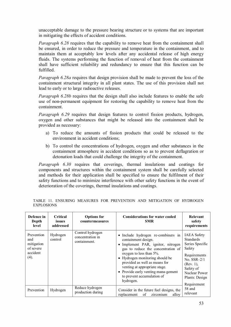
53
unacceptable damage to the pressure bearing structure or to systems that are important
in mitigating the effects of accident conditions.
Paragraph 6.28 requires that the capability to remove heat from the containment shall
be ensured, in order to reduce the pressure and temperature in the containment, and to
maintain them at acceptably low levels after any accidental release of high energy
fluids. The systems performing the function of removal of heat from the containment
shall have sufficient reliability and redundancy to ensure that this function can be
fulfilled.
Paragraph 6.28a requires that design provision shall be made to prevent the loss of the
containment structural integrity in all plant states. The use of this provision shall not
lead to early or to large radioactive releases.
Paragraph 6.28b requires that the design shall also include features to enable the safe
use of non-permanent equipment for restoring the capability to remove heat from the
containment.
Paragraph 6.29 requires that design features to control fission products, hydrogen,
oxygen and other substances that might be released into the containment shall be
provided as necessary:
a) To reduce the amounts of fission products that could be released to the
environment in accident conditions;
b) To control the concentrations of hydrogen, oxygen and other substances in the
containment atmosphere in accident conditions so as to prevent deflagration or
detonation loads that could challenge the integrity of the containment.
Paragraph 6.30 requires that coverings, thermal insulations and coatings for
components and structures within the containment system shall be carefully selected
and methods for their application shall be specified to ensure the fulfilment of their
safety functions and to minimize interference with other safety functions in the event of
deterioration of the coverings, thermal insulations and coatings.
TABLE 11. ENSURING MEASURES FOR PREVENTION AND MITIGATION OF HYDROGEN
EXPLOSIONS
TABLE 11 (cont.)
Defence in
Depth
level
Critical
issues
addressed
Options for
countermeasures
Considerations for water cooled
SMR
Relevant
safety
requirements
Prevention
and
mitigation
of severe
accident (4).
Hydrogen
control
Control hydrogen
concentration in
containment.
• Include hydrogen re-combiners in
containment design.
• Implement PAR, ignitor, nitrogen
gas to reduce the concentration of
oxygen to less than 5%.
• Hydrogen monitoring should be
provided as well as means for
venting at appropriate stage.
• Provide early venting mana-gement
to prevent accumulation of
hydrogen.
IAEA Safety
Standards
Series Specific
Safety
Requirements No. SSR–2/1
(Rev. 1),
Safety of
Nuclear Power
Plants: Design
Requirement
58 and
relevant Prevention Hydrogen
Reduce hydrogen
production during Consider in the future fuel designs, the
replacement of zirconium alloy
54
TABLE 11 (cont.)
Defence in
Depth
level
Critical
issues
addressed
Options for
countermeasures
Considerations for water cooled
SMR
Relevant
safety
requirements
(1) control accident by design. cladding by ceramic compounds, such
as silicon carbide (SiC).
Paragraphs.
[11]
Control of
accidents
within DB
(3)
Hydrogen
control
Prevent core melt
accidents. Provide adequate alternative heat
removal systems to assure that core
melt can be avoided.
Enhance containment venting and filtering system 4.1.7.
The BWR venting system is part of containment system which plays an important role to
control the pressure of dry well and wet well during abnormal conditions. For reactors with
Mark I containments, there are several locations of venting as can be seen in FIG. 24.
During the Fukushima Daiichi accident, the remote venting could not be implemented
properly from the control room due to unavailability of electric power, and local manual
venting was delayed due to several practical difficulties such as:
– High radiation dose;
– Lack of control air;
– Lack of DC power;
– Procedure approval;
– Lack of command and control;
– Lack of lighting; and
– Communication difficulties.
In addition, there were no alternative power sources for instrumentation and control for
over 30 minutes and no SAMG were written for this situation. As venting is an important
aspect in coping with the Fukushima Daiichi type accident, the following considerations
given in TABLE 12 are presented to deal with this type of accident.
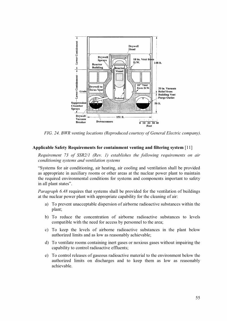
55
Applicable Safety Requirements for containment venting and filtering system [11]
Requirement 73 of SSR2/1 (Rev. 1) establishes the following requirements on air
conditioning systems and ventilation systems
“Systems for air conditioning, air heating, air cooling and ventilation shall be provided
as appropriate in auxiliary rooms or other areas at the nuclear power plant to maintain
the required environmental conditions for systems and components important to safety
in all plant states”.
Paragraph 6.48 requires that systems shall be provided for the ventilation of buildings
at the nuclear power plant with appropriate capability for the cleaning of air:
a) To prevent unacceptable dispersion of airborne radioactive substances within the
plant;
b) To reduce the concentration of airborne radioactive substances to levels
compatible with the need for access by personnel to the area;
c) To keep the levels of airborne radioactive substances in the plant below
authorized limits and as low as reasonably achievable;
d) To ventilate rooms containing inert gases or noxious gases without impairing the
capability to control radioactive effluents;
e) To control releases of gaseous radioactive material to the environment below the
authorized limits on discharges and to keep them as low as reasonably
achievable.
FIG. 24. BWR venting locations (Reproduced courtesy of General Electric company).

56
TABLE 12. CONSIDERATIONS TO ENHANCE THE CONTAINMENT VENTING AND
FILTERING SYSTEM
Defence in
Depth
level
Critical
issues
addressed
Options for
countermeasures
Considerations or engineered
features to be added and/or
modified
Relevant safety
requirements
Mitigation
of severe
accidents
(4)
Vent design Ensure that the vent design
is hardened and capable to
allow safe
depressurization.
• The vent system should be
constructed to accommodate a
permissible flow of steam/air
mixture. The system should be able to reduce pressure inside
the reactor before core uncovery
(e.g., 1 hour for BWR [21]).
• Plant designs should support
timely venting of primary
containment even with a loss of
power and motive force, such as
compressed air.
• The installation of manual vents in each reactor building may be
prudent to allow venting of any
hydrogen that may have
accumulated.
IAEA Safety
Standards Series
Specific Safety
Requirements
No. SSR–2/1 (Rev. 1), Safety
of Nuclear
Power Plants:
Design
Requirement 73
and relevant
Paragraphs. [11]
Mitigation
of severe
accidents (4)
Radioactive
release
control
Avoid radioactive release
during venting. Retrofit the vent system with
radioactivity filters to reduce the
pressure and hydrogen level without releasing large amounts of
fission products [22].
Mitigation
of severe
accident (4)
Vent design Ensure each reactor unit
has independent venting
system.
Provide dedicated vents for each
unit, or make provisions to prevent
backflow between units [18].
Mitigation
of severe
accident (4)
Vent design Ensure ability to
accomplish local manual
venting [18].
Provide venting valves that are
accessible for manual operation.
Ensure hardened instrumentation and cables for safety-related parameters 4.1.8.
and monitoring equipment
In the Fukushima Daiichi accident, after the accident progressed into severe accident,
instruments and monitoring equipment were exposed to beyond design basis environment.
Some unreliable measurements were observed, such as reactor water level of Unit 1 and
suppression chamber pressure of Unit 2. As a result it hampered operators to understand
the conditions and respond correctly.
Learning from such experience, TABLE 13 lists the options of countermeasure to ensure
safety parameter and monitoring equipment functions.
57
Applicable Safety Requirements for instrumentation and cables for safety-related
parameters and monitoring equipment [11]
Requirement 59 of SSR–2/1 (Rev. 1) establishes the following requirements on provision
of instrumentation.
“Instrumentation shall be provided for determining the values of all the main variables
that can affect the fission process, the integrity of the reactor core, the reactor coolant
systems and the containment at the nuclear power plant, for obtaining essential
information on the plant that is necessary for its safe and reliable operation, for
determining the status of the plant in accident conditions and for making decisions for
the purposes of accident management”.
Paragraph 6.31 requires that instrumentation and recording equipment shall be
provided to ensure that essential information is available for monitoring the status of
essential equipment and the course of accidents, for predicting the locations of release
and the amount of radioactive material that could be released from the locations that are
so intended in the design, and for post-accident analysis.
Requirement 62 of SSR-2/1 (Rev. 1) establishes the following requirements on reliability
and testability of instrumentation and control systems.
“Instrumentation and control systems for items important to safety at the nuclear power
plant shall be designed for high functional reliability and periodic testability
commensurate with the safety function(s) to be performed”.
Paragraph 6.34 requires that design techniques such as testability, including a self-
checking capability where necessary, fail-safe characteristics, functional diversity and
diversity in component design and in concepts of operation shall be used to the extent
practicable to prevent loss of a safety function.
Paragraph 6.35 requires that safety systems shall be designed to permit periodic testing
of their functionality when the plant is in operation, including the possibility of testing
channels independently for the detection of failures and losses of redundancy. The
design shall permit all aspects of functionality testing for the sensor, the input signal,
the final actuator and the display.
Paragraph 6.36 requires that when a safety system, or part of a safety system, has to be
taken out of service for testing, adequate provision shall be made for the clear indication
of any protection system bypasses that are necessary for the duration of the testing or
maintenance activities.
Requirement 71 establishes the following requirements on process sampling systems
and post-accident sampling systems.
“Process sampling systems and post-accident sampling systems shall be provided for
determining, in a timely manner, the concentration of specified radionuclides in fluid
process systems, and in gas and liquid samples taken from systems or from the
environment, in all operational states and in accident conditions at the nuclear power
plant”.
58
TABLE 13. ENSURING HARDENED INSTRUMENTATION AND CABLES FOR SAFETY–RELATED
PARAMETERS AND MONITORING EQUIPMENT
Defence in
Depth level
Critical
issues
addressed
Options for
countermeasures
Considerations or engineered features
to be added and/or modified
Relevant safety
requirements
Mitigation
of severe
accidents (4)
Hardened
monitoring
system
Ensure post-accident
instrumentation for
safety related
parameters and
monitoring
equipments [22].
• Provide alternate DC Power for post-
accident monitoring system to ensure
its availability in case of loss of DC
Power along with station blackout.
The system and cables should be
placed and run in hardened housings
to withstand severe accidents [23].
• Enhance the instrumentation in the Reactor pressure vessel to provide the
operator with better and diverse
monitoring means about the course of
a core degradation during postulated
design base and sever accidents
IAEA Safety
Standards Series
Specific Safety
Requirements
No. SSR–2/1
(Rev. 1), Safety
of Nuclear
Power Plants: Design
Requirement 59,
62 and relevant
Paragraphs. [11]
Enhanced robustness of spent fuel cooling 4.1.9.
In the Fukushima Daiichi accident, hydrogen explosion occured in the reactor building of
Unit 4. The failure of spent fuel pool (SFP) monitoring system put the operators in the dark
about the actual status. Due to this, after the explosion the emergency team had a
consideration that the pool cooling system had failed or lost capability and the fuel
assemblies were uncovered leading to overheating and fuel cladding-steam reaction
producing hydrogen that caused detonation. It was later learnt that the hydrogen came from
a back-flow of Unit 3 as the containment vent exhaust pipings of Units 3 and 4 were
connected.
Lack of knowledge about the SFP conditions created confusion and distraction. Efforts
were placed to reduce the temperature of the SFP by water spray from above, i.e. using
helicopters and fire engines. Investigation showed that the fuel remained covered during
the accident and no spent fuel was damaged. This shows the necessity to enhance the
robustness of SFP cooling and its monitoring.
Spent fuel contains large inventory of radioactivity. Most nuclear plants store and manage
their spent fuels in a pool inside the plants. As the fuels still produce heat during their
decaying phase, the cooling system for the pool is important to control the spent fuel
temperature. Hence, it is necessary to provide a robust and reliable cooling system for the
SFP. Moreover, the water level and temperature of SFP must be constantly monitored as
failure of the cooling system could lead to water vaporization and fuel uncovery.
In some water cooled SMR designs, spent fuels are handled in a particular manner
depending on where the refueling mode is performed. For example, some SMRs do not
require on site SFP as the refueling is performed through a replacement of the whole
module and the fuel is taken out in the vendor workshop which may be far away from the
site. However, for design with conventional onsite refueling method, the issues of SFP
should be considered as proposed in TABLE 14 below.

59
Applicable Safety Requirements for spent fuel cooling [11]
Requirement 80 of SSR-2/1 (Rev. 1) establishes the following requirements on fuel
handling and storage systems.
“Fuel handling and storage systems shall be provided at the nuclear power plant to
ensure that the integrity and properties of the fuel are maintained at all times during fuel
handling and storage”.
Paragraph 6.64 requires that the design of the plant shall incorporate appropriate
features to facilitate the lifting, movement and handling of fresh fuel and spent fuel.
Paragraph 6.65 requires that the design of the plant shall be such as to prevent any
significant damage to items important to safety during the transfer of fuel or casks, or in
the event of fuel or casks being dropped.
Paragraph 6.66 requires that the fuel handling and storage systems for irradiated and
non-irradiated fuel shall be designed:
a) To prevent criticality by a specified margin, by physical means or by means of
physical processes, and preferably by use of geometrically safe configurations,
even under conditions of optimum moderation;
b) To permit inspection of the fuel;
c) To permit maintenance, periodic inspection and testing of components important
to safety;
d) To prevent damage to the fuel;
e) To prevent the dropping of fuel in transit;
f) To provide for the identification of individual fuel assemblies (g) To provide
proper means for meeting the relevant requirements for radiation protection;
g) To ensure that adequate operating procedure and a system of accounting for, and
control of, nuclear fuel can be implemented to prevent any loss of, or loss of
control over, nuclear fuel.
Paragraph 6.67 requires that the fuel handling and storage systems for irradiated fuel
shall be designed:
a) To permit adequate removal of heat from the fuel in operational states and in
accident conditions;
b) To prevent the dropping of spent fuel in transit;
c) To prevent causing unacceptable handling stresses on fuel elements or fuel
assemblies;
d) To prevent the potentially damaging dropping on the fuel of heavy objects such
as spent fuel casks, cranes or other objects;
e) To permit safe keeping of suspect or damaged fuel elements or fuel assemblies;
f) To control levels of soluble absorber if this is used for criticality safety;
g) To facilitate maintenance and future decommissioning of fuel handling and
storage facilities;
h) To facilitate decontamination of fuel handling and storage areas and equipment
when necessary;
60
i) To accommodate, with adequate margins, all the fuel removed from the reactor
in accordance with the strategy for core management that is foreseen and the
amount of fuel in the full reactor core;
j) To facilitate the removal of fuel from storage and its preparation for offsite
transport.
Paragraph 6.68 requires that the design shall prevent the uncovering of fuel assemblies
for reactors using a water pool system for fuel storage in all plant states that are of
relevance for the spent fuel pool, so as to practically eliminate the possibility of early or
large radioactive releases and to avoid high radiation fields on the site. The design of
the plant:
a) Shall provide the necessary fuel cooling capabilities;
b) Shall provide features to prevent the uncovering of fuel assemblies in the event
of a leak or a pipe break;
c) Shall provide a capability to restore the water inventory.
The design shall also include features to enable the safe use of non-permanent
equipment to ensure sufficient water inventory for the long term cooling of spent fuel
and for providing shielding against radiation.
Paragraph 6.68a requires that the design shall include the following:
a) Means for monitoring and controlling the water temperature for operational
states and for accident conditions that are of relevance for the spent fuel pool;
b) Means for monitoring and controlling the water level for operational states and
for accident conditions that are of relevance for the spent fuel pool;
c) Means for monitoring and controlling the activity in water and in air for
operational states and means for monitoring the activity in water and in air for
accident conditions that are of relevance for the spent fuel pool;
d) Means for monitoring and controlling the water chemistry for operational states.
TABLE 14. CONSIDERATIONS TO ENHANCE ROBUSTNESS OF SPENT FUEL COOLING
TABLE 14 (cont.)
Defence in
Depth level
Critical
issues
addressed
Options for
countermeasures
Considerations or engineered
features to be added and/or
modified
Relevant safety
requirements
Prevention (1)
Cooling system
Secure the spent fuel pool (SFP) cooling
function [16].
• Provide passive cooling system for SFP.
• Provide diversity of pool water
injection method [16].
IAEA Safety Standards Series
Specific Safety
Requirements
No. SSR–2/1
(Rev. 1), Safety
of Nuclear
Power Plants:
Design
Requirement 80
and relevant
Paragraphs. [11]
Prevention
(1)
SFP
protection
Secure the SFP from
external hazards. Provide robust shielding to avoid
and mitigate spent fuel damage.
Prevention
(1)
Fuel Risk Reduce the spent fuel
risk. Several SMRs solutions use SFP or
pit below grade. Due to the size of
the core, lesser decay heat and
source term can be considered.

61
TABLE 14 (cont.)
Defence in
Depth level
Critical
issues
addressed
Options for
countermeasures
Considerations or engineered
features to be added and/or
modified
Relevant safety
requirements
Prevention
(1)
Integrity Ensure the integrity and
leak tightness of SFP. • SFP has a large inventory of
radio-activity. The coping period
for SFPs cooling and shielding is
very long because a large
inventory is provided. The ability
of the pool to maintain leak-
tightness & integrity in normal
conditions and during natural
phenomena should be confirmed in crediting the coping period
• Diverse, robust and strengthened
external make-up cooling should
be provided to further extend this
coping time.
Mitigation
of severe
accident(4)
Monitoring
system
Ensure availability of
monitoring system. Incorporate additional diversified
SFP temperature and water level
monitoring systems in case of
severe accidents that are also
displayed in the main control room
[17].
Mitigation of severe
accident (4)
Severe accident
Consider severe accident management in
SFP design.
Include corium coolability and hydrogen management in design.
Use of effective probabilistic safety assessment for risk assessment and 4.1.10.
management
Probabilistic safety assessment (PSA) is an essential tool to practically understand the
important part of safety system in NPPs. Generally, the assessment is conducted and
completed for a wide range of accident scenarios in NPPs prior to operation. However, the
Fukushima Daiichi accident indicated that many accident progression scenarios were not
properly taken into account in the PSA although physical consequences of the events were
largely in line with previous understanding. Analysis of plant had not previously
considered all the failure modes that occurred. It is obvious that some issues related with
PSA should be reviewed and reconsidered for the reactor design and more emphasis should
be placed on these issues as they could not draw proper attention so far. The following are
some countermeasures to address the PSA issues TABLE 15:
Applicable Safety Requirements for risk assessment and management [11]
Requirement 42 of SSR-2/1 (Rev. 1) establishes the following requirements on safety
analysis of the plant design.
“A safety analysis of the design for the nuclear power plant shall be conducted in which
methods of both deterministic analysis and probabilistic analysis shall be applied to

62
enable the challenges to safety in the various categories of plant states to be evaluated
and assessed”.
Paragraph 5.70 requires that the design basis for items important to safety and their
links to initiating events and event sequences shall be confirmed on the basis of a safety
analysis.
Paragraph 5.71 requires that it shall be demonstrated that the nuclear power plant as
designed is capable of complying with authorized limits on discharges with regard to
radioactive releases and with the dose limits in all operational states, and is capable of
meeting acceptable limits for accident conditions.
Paragraph 5.72 requires that the safety analysis shall provide assurance that defence in
depth has been implemented in the design of the plant.
Paragraph 5.73 requires that the safety analysis shall provide assurance that
uncertainties have been given adequate consideration in the design of the plant and
especially that adequate margins are available to avoid cliff edge effects and large or
early radioactive releases.
Paragraph 5.74 requires that the applicability of the analytical assumptions, methods
and degree of conservatism used in the design of the plant shall be updated and verified
for the current or as built design.
Paragraph 5.76 requires that the design shall take due account of the probabilistic
safety analysis of the plant for all modes of operation and for all plant states, including
shutdown, with particular reference to:
a) Establishing that a balanced design has been achieved such that no particular
feature or postulated initiating event makes a disproportionately large or
significantly uncertain contribution to the overall risks, and that, to the extent
practicable, the levels of defence in depth are independent;
b) Providing assurance that small deviation in plant parameters that could give rise
to large variations in plant conditions (cliff edge effects) will be prevented;
c) Comparing the results of the analysis with the acceptance criteria for risk where
these have been specified.
TABLE 15. CONSIDERATION OF THE USE OF PSA EFFECTIVELY FOR RISK ASSESSMENT AND
MANAGEMENT
TABLE 15 (cont.)
Defence in
Depth level
Critical
issues
addressed
Options for
countermeasures
Considerations or engineered features to
be added and/or modified
Relevant
safety
requirements
Prevention
(1)
Cliff edge
effect
Use PSA to
eliminate cliff edge
effect.
PSA can be used to provide insights on
which systems are candidates for
strengthening to remove cliff edge effects
as the magnitude of the natural hazards
increases. In using PSA to consider reduction in core damaged frequency (CDF)
vs. reduction in large early release
frequency (LERF), comparison should be to
a CDF criteria (which in turn prevents
LERF), there may be sites/cases where
preventing large early release, to limit off
IAEA Safety
Standards
Series Specific
Safety
Requirements No. SSR–2/1
(Rev. 1),
Safety of
Nuclear Power
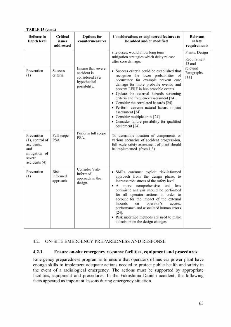
63
TABLE 15 (cont.)
Defence in
Depth level
Critical
issues
addressed
Options for
countermeasures
Considerations or engineered features to
be added and/or modified
Relevant
safety
requirements
site doses, would allow long term
mitigation strategies which delay release
after core damage.
Plants: Design
Requirement
43 and
relevant
Paragraphs.
[11]
Prevention
(1)
Success
criteria
Ensure that severe
accident is
considered as a
hypothetical
possibility.
• Success criteria could be established that
recognize the lower probabilities of
occurrence for example prevent core
damage for more probable events, and
prevent LERF in less probable events.
• Update the external hazards screening
criteria and frequency assessment [24].
• Consider the correlated hazards [24].
• Perform extreme natural hazard impact
assessment [24].
• Consider multiple units [24].
• Consider failure possibility for qualified
equipment [24].
Prevention
(1), control of accidents,
and
mitigation of
severe
accidents (4)
Full scope
PSA
Perform full scope
PSA. To determine location of components or
various scenarios of accident progress-ion, full scale safety assessment of plant should
be implemented. (from 1.3)
Prevention
(1)
Risk
informed
approach
Consider ‘risk-
informed’
approach in the
design.
• SMRs can/must exploit risk-informed
approach from the design phase, to
increase robustness of the safety level.
• A more comprehensive and less
optimistic analysis should be performed
for all operator actions in order to
account for the impact of the external hazards on operator’s access,
performance and associated human errors
[24].
• Risk informed methods are used to make
a decision on the design changes.
ON-SITE EMERGENCY PREPAREDNESS AND RESPONSE 4.2.
Ensure on-site emergency response facilities, equipment and procedures 4.2.1.
Emergency preparedness program is to ensure that operators of nuclear power plant have
enough skills to implement adequate actions needed to protect public health and safety in
the event of a radiological emergency. The actions must be supported by appropriate
facilities, equipment and procedures. In the Fukushima Daiichi accident, the following
facts appeared as important lessons during emergency situation.

64
It was recognized that the on-site emergency response center (which is located in a
seismically isolated building) of Unit 1 was very useful. In addition, non-safety related
systems played important roles to block the damage progression. However the loss of
power supplies disabled many communication equipments. As a result, outside help or
advice was limited and inefficient on-site communication systems delayed and complicated
the necessary recovery actions. In addition, loss of light was also a major issue. The ability
to physically locate and manually operate valves and equipment in the darkness was very
important. In addition, the loss of electricity supply to the heating ventilating air
conditioning system (HVAC) also aggravated the accessibility. This suggests that on-site
emergency response facilities should be of the same safety class as safety system
equipment. It was also found that lack of standard external power connections delayed re-
energization.
Procedural sets, including SAMG, did not cover this level of accident. Gross radioactive
contamination of the whole site had not been considered in the manuals or procedures.
Many actions were conducted in such a difficult situation based on the operator’s
understanding and judgment on what was occurring. TABLE 16 lists considerations to deal
with this type of accident.
Applicable Safety Requirements for on-site emergency response facilities, equipments
and procedures [11]
Paragraph 2.10 of SSR–2/1 (Rev. 1) requires that measures shall are required to be
taken to control exposure for all operational states at levels that are as low as reasonably
achievable and to minimize the likelihood of an accident that could lead to the loss of
control over a source of radiation. Nevertheless, there will remain a possibility that an
accident could happen. Measures shall are required to be taken to ensure that the
radiological consequences of an accident would be mitigated. Such measures include
the provision of safety features and safety systems, the establishment of accident
management procedures by the operating organization and, possibly, the establishment
of off-site intervention measures by the appropriate authorities, supported as necessary
by the operating organization, to mitigate exposures if an accident has occurred.
Requirement 67 of SSR-2/1 (Rev. 1) establishes the following requirements on
emergency response facilities control centre on the site.
“The nuclear power plant shall include the necessary emergency response facilities on
the site. Their design shall be such that personnel will be able to perform expected tasks
for managing an emergency under conditions generated by accidents and hazards”.
Paragraph 6.42 requires that information about important plant parameters and
radiological conditions at the nuclear power plant and in its immediate surroundings
shall be provided to the relevant emergency response facilities. Each facility shall be
provided with means of communication with, as appropriate, the control room, the
supplementary control room and other important locations at the plant, and with on-site
and off-site emergency response organizations.
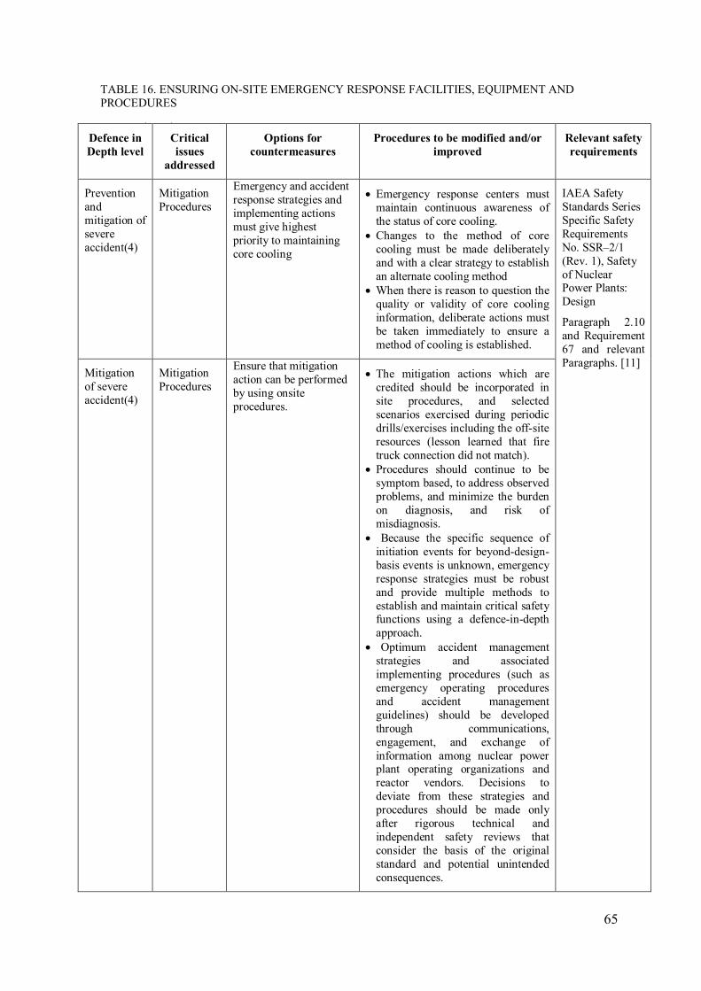
65
TABLE 16. ENSURING ON-SITE EMERGENCY RESPONSE FACILITIES, EQUIPMENT AND
PROCEDURES
TABLE 16 (cont.)
Defence in
Depth level
Critical
issues
addressed
Options for
countermeasures
Procedures to be modified and/or
improved
Relevant safety
requirements
Prevention
and
mitigation of
severe
accident(4)
Mitigation
Procedures
Emergency and accident
response strategies and
implementing actions
must give highest
priority to maintaining
core cooling
• Emergency response centers must
maintain continuous awareness of
the status of core cooling.
• Changes to the method of core
cooling must be made deliberately
and with a clear strategy to establish
an alternate cooling method
• When there is reason to question the
quality or validity of core cooling
information, deliberate actions must
be taken immediately to ensure a
method of cooling is established.
IAEA Safety
Standards Series
Specific Safety
Requirements
No. SSR–2/1
(Rev. 1), Safety
of Nuclear Power Plants:
Design
Paragraph 2.10
and Requirement
67 and relevant
Paragraphs. [11] Mitigation
of severe
accident(4)
Mitigation
Procedures
Ensure that mitigation
action can be performed
by using onsite
procedures.
• The mitigation actions which are
credited should be incorporated in
site procedures, and selected
scenarios exercised during periodic
drills/exercises including the off-site
resources (lesson learned that fire
truck connection did not match).
• Procedures should continue to be
symptom based, to address observed
problems, and minimize the burden
on diagnosis, and risk of
misdiagnosis.
• Because the specific sequence of
initiation events for beyond-design-
basis events is unknown, emergency
response strategies must be robust
and provide multiple methods to
establish and maintain critical safety functions using a defence-in-depth
approach.
• Optimum accident management
strategies and associated
implementing procedures (such as
emergency operating procedures
and accident management
guidelines) should be developed
through communications,
engagement, and exchange of
information among nuclear power plant operating organizations and
reactor vendors. Decisions to
deviate from these strategies and
procedures should be made only
after rigorous technical and
independent safety reviews that
consider the basis of the original
standard and potential unintended
consequences.
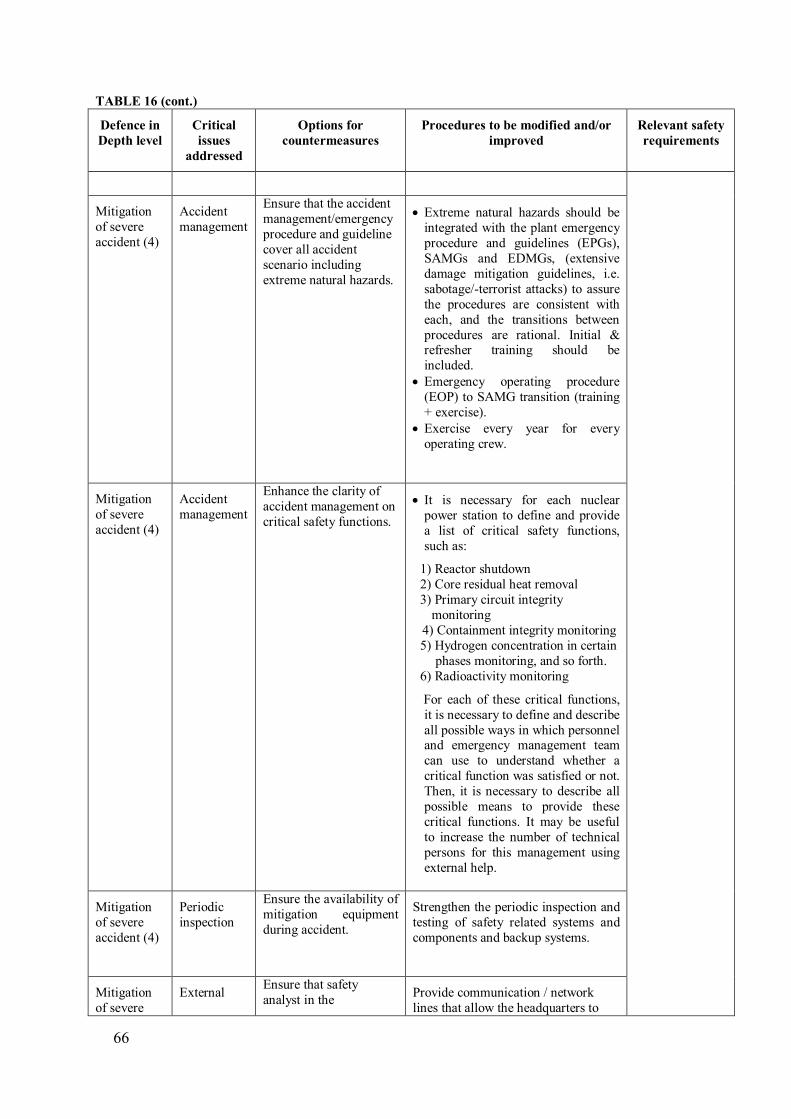
66
TABLE 16 (cont.)
Defence in
Depth level
Critical
issues
addressed
Options for
countermeasures
Procedures to be modified and/or
improved
Relevant safety
requirements
Mitigation
of severe
accident (4)
Accident
management
Ensure that the accident
management/emergency
procedure and guideline
cover all accident
scenario including
extreme natural hazards.
• Extreme natural hazards should be
integrated with the plant emergency
procedure and guidelines (EPGs),
SAMGs and EDMGs, (extensive
damage mitigation guidelines, i.e.
sabotage/-terrorist attacks) to assure
the procedures are consistent with
each, and the transitions between
procedures are rational. Initial & refresher training should be
included.
• Emergency operating procedure
(EOP) to SAMG transition (training
+ exercise).
• Exercise every year for every
operating crew.
Mitigation
of severe
accident (4)
Accident
management
Enhance the clarity of
accident management on
critical safety functions.
• It is necessary for each nuclear
power station to define and provide
a list of critical safety functions,
such as:
1) Reactor shutdown
2) Core residual heat removal
3) Primary circuit integrity
monitoring
4) Containment integrity monitoring
5) Hydrogen concentration in certain
phases monitoring, and so forth.
6) Radioactivity monitoring
For each of these critical functions,
it is necessary to define and describe
all possible ways in which personnel and emergency management team
can use to understand whether a
critical function was satisfied or not.
Then, it is necessary to describe all
possible means to provide these
critical functions. It may be useful
to increase the number of technical
persons for this management using
external help.
Mitigation
of severe
accident (4)
Periodic
inspection
Ensure the availability of
mitigation equipment
during accident.
Strengthen the periodic inspection and
testing of safety related systems and
components and backup systems.
Mitigation
of severe
External Ensure that safety
analyst in the Provide communication / network
lines that allow the headquarters to

67
TABLE 16 (cont.)
Defence in
Depth level
Critical
issues
addressed
Options for
countermeasures
Procedures to be modified and/or
improved
Relevant safety
requirements
accident (4) advise headquarters is able to
supervise and provide
adequate advice to on-
site workers and
engineers.
see/monitor the control room displays
and indications.
Mitigation
of severe
accident (4)
Emergency
equipment
Enhance the
communication and the
availability of
emergency lighting
sources.
• Adopt dependable communication
equipment.
• Adopt dependable lighting
equipment.
• Independent battery-powered emergency lights in the main control
room and key building walkways
are needed in the event that normal
AC power and DC power are lost.
Mitigation of severe
accident (4)
SAMG Ensure that a plant specific SAMG has been
developed.
Provide plant specific SAMG.
Mitigation
of severe
accident
(4)
Emergency
response
Ensure the availability
of monitoring
equipment to diagnose
and initiate response.
• Install active warning system in
remote locations near the source of
external natural event or at most
sensitive location.
• The mitigation plans may involve
additional monitoring equipment to
speed diagnosis. The mitigation
plan can include robust offsite
assistance, including transit time to
the site.
• Provide mobile equipment [25].
Mitigation
of severe
accident (4)
Emergency
response
Emergency response
needs are expected to be
minimal due to SMR’s
small source term and
high level of safety.
• Justify that source term is small and
level of safety is high.
• Justify that emergency response
resources needed are minimal.
Mitigation
of severe
accident (4)
Emergency
response
Ensure that ER facilities
incorporate impacts of
credible natural
disasters, staff loading,
radiation effects and
duration of site wide emergencies [17].
• Provide prompt access to primary
and alternate use points for beyond
design basis prestaged equipment
[18].
• Provide standard mechanical and
electrical interface connections with prestaged onsite and offsite beyond
design basis equipment [18].
Enhance human resource, skill and capabilities 4.2.2.
Human capabilities and capacities are very important during emergency situation. Every
decision is critical, and any misunderstanding can cause a wrong action that may lead to a
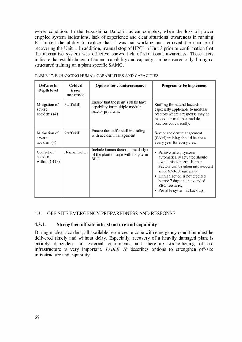
68
worse condition. In the Fukushima Daiichi nuclear complex, when the loss of power
crippled system indications, lack of experience and clear situational awareness in running
IC limited the ability to realize that it was not working and removed the chance of
recovering the Unit 1. In addition, manual stop of HPCI in Unit 3 prior to confirmation that
the alternative system was effective shows lack of situational awareness. These facts
indicate that establishment of human capability and capacity can be ensured only through a
structured training on a plant specific SAMG.
TABLE 17. ENHANCING HUMAN CAPABILITIES AND CAPACITIES
Defence in
Depth level
Critical
issues
addressed
Options for countermeasures Program to be implement
Mitigation of
severe
accidents (4)
Staff skill Ensure that the plant’s staffs have
capability for multiple module
reactor problems.
Staffing for natural hazards is
especially applicable to modular
reactors where a response may be
needed for multiple module
reactors concurrently.
Mitigation of
severe
accident (4)
Staff skill Ensure the staff’s skill in dealing
with accident management. Severe accident management
(SAM) training should be done
every year for every crew.
Control of
accident within DB (3)
Human factor Include human factor in the design
of the plant to cope with long term SBO.
• Passive safety systems
automatically actuated should avoid this concern; Human
Factors can be taken into account
since SMR design phase.
• Human action is not credited
before 7 days in an extended
SBO scenario.
• Portable system as back up.
OFF-SITE EMERGENCY PREPAREDNESS AND RESPONSE 4.3.
Strengthen off-site infrastructure and capability 4.3.1.
During nuclear accident, all available resources to cope with emergency condition must be
delivered timely and without delay. Especially, recovery of a heavily damaged plant is
entirely dependent on external equipments and therefore strengthening off-site
infrastructure is very important. TABLE 18 describes options to strengthen off-site
infrastructure and capability.
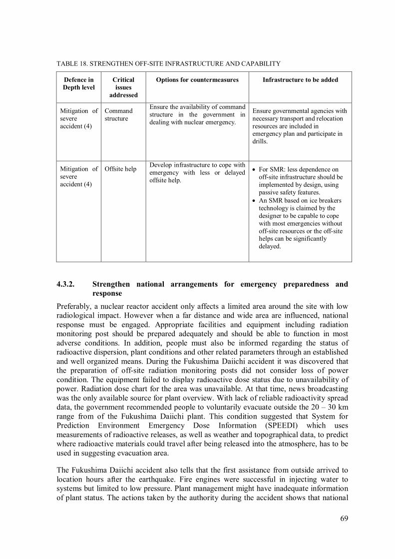
69
TABLE 18. STRENGTHEN OFF-SITE INFRASTRUCTURE AND CAPABILITY
Defence in
Depth level
Critical
issues
addressed
Options for countermeasures Infrastructure to be added
Mitigation of
severe
accident (4)
Command
structure
Ensure the availability of command
structure in the government in
dealing with nuclear emergency.
Ensure governmental agencies with
necessary transport and relocation
resources are included in emergency plan and participate in
drills.
Mitigation of
severe
accident (4)
Offsite help Develop infrastructure to cope with
emergency with less or delayed
offsite help.
• For SMR: less dependence on
off-site infrastructure should be
implemented by design, using
passive safety features.
• An SMR based on ice breakers
technology is claimed by the
designer to be capable to cope
with most emergencies without
off-site resources or the off-site helps can be significantly
delayed.
Strengthen national arrangements for emergency preparedness and 4.3.2.
response
Preferably, a nuclear reactor accident only affects a limited area around the site with low
radiological impact. However when a far distance and wide area are influenced, national
response must be engaged. Appropriate facilities and equipment including radiation
monitoring post should be prepared adequately and should be able to function in most
adverse conditions. In addition, people must also be informed regarding the status of
radioactive dispersion, plant conditions and other related parameters through an established
and well organized means. During the Fukushima Daiichi accident it was discovered that
the preparation of off-site radiation monitoring posts did not consider loss of power
condition. The equipment failed to display radioactive dose status due to unavailability of
power. Radiation dose chart for the area was unavailable. At that time, news broadcasting
was the only available source for plant overview. With lack of reliable radioactivity spread
data, the government recommended people to voluntarily evacuate outside the 20 – 30 km
range from of the Fukushima Daiichi plant. This condition suggested that System for
Prediction Environment Emergency Dose Information (SPEEDI) which uses
measurements of radioactive releases, as well as weather and topographical data, to predict
where radioactive materials could travel after being released into the atmosphere, has to be
used in suggesting evacuation area.
The Fukushima Daiichi accident also tells that the first assistance from outside arrived to
location hours after the earthquake. Fire engines were successful in injecting water to
systems but limited to low pressure. Plant management might have inadequate information
of plant status. The actions taken by the authority during the accident shows that national

70
emergency preparedness and response plans were insufficient in dealing with multiple
infrastructure damage after the earthquake and tsunami. The frequency of emergency
preparedness drills involving whole public and stakeholders should be considered for
lower frequency and be evaluated accordingly.
Bearing in mind the previous lessons, it is necessary to prepare national arrangement for a
nuclear emergency. The TABLE 19 provides some useful considerations.
TABLE 19. STRENGTHENING NATIONAL ARRANGEMENTS FOR EMERGENCY PREPAREDNESS
AND RESPONSE
Defence in
Depth level
Critical
issues
addressed
Options for countermeasures Infrastructure to be modified
and/or improved
Mitigation of
severe accident
(4)
National
team
Establish national team for severe
accident management. Build up the technical support team
consisting of designers and
operators for decision making (severe accident counter-actions
under very harsh environment).
Mitigation of
severe accident
(4)
Unified
control
Harmonize national coordination. Strengthen the unified control and
decision making centre to make it
easier and faster to avoid any
conflict.
Mitigation of
radiological
consequences
(5)
Public
education
Ensure public awareness of
emergency situation. More public education on
emergency preparedness is
necessary.
Mitigation of
severe accident
(4)
Direct
communicat
ion
Established direct communication
among decision making people.
It is necessary to organize direct
and effective communication
among decision making people in
the accident management centre. It should not be any intermediate-
chain in communication.
Enhance interaction and communication with the international communities 4.3.3.
Fukushima Daiichi accident shows the need for international collaboration in dealing with
nuclear accident. The radioactive materials spreading across the air and ocean more or less
have affected neighbouring countries and environments. In a nuclear accident people shall
work together to cope the situation. International communication and contact are needed to
let the cooperation succeeds. One country with specific expertise can provide technical
help for others that need it. The following are options on enhancing the interaction and
communication with international communities.

71
TABLE 20. ENHANCING INTERACTION AND COMMUNICATION WITH THE INTERNATIONAL
COMMUNITY
Defence in
Depth Level
Critical
Issues
addressed
Options for countermeasures Infrastructure to be added
Mitigation of
severe accident
(4)
Equipment
exchange
Establish emergency equipment
exchange agreement with
international community.
• Plans should be in place to bring
equipment from the closest
adjacent nuclear plants, even if
these are operated by a different utility/company or in a different
country. This should be part of
the response plan and included in
drills.
• Establish a regional resource
center for long term cooling
needs.
Mitigation of
radiological
consequences
(5)
Information
centre
Established information centre for
international community. Report all of the crucial events and
stabilization efforts of the plants to
international communities.
NUCLEAR SAFETY INFRASTRUCTURES 4.4.
Review and clarify regulatory and emergency response framework 4.4.1.
Nuclear power complex is a work environment where management and employees are
committed to put the safety as first priority. The commitment must be placed in a clear
regulatory framework and the documents should contain logical, systematic and coherent
regulations for adequate protection including the role and responsibility of relevant
organizations.
It was noted that during the Fukushima Daiichi accident lack of clarity on some command
and control issues (e.g., failure to report the IC status of Unit 1 to emergency response
center) was part of situation which impeded the coping of emergency condition. There was
also the decision issue for the evacuation and venting instructions. These problems show
that accident mitigation plans were not adequately developed.
Noticing these lessons, TABLE 21 describes some considerations important to nuclear
safety infrastructure.
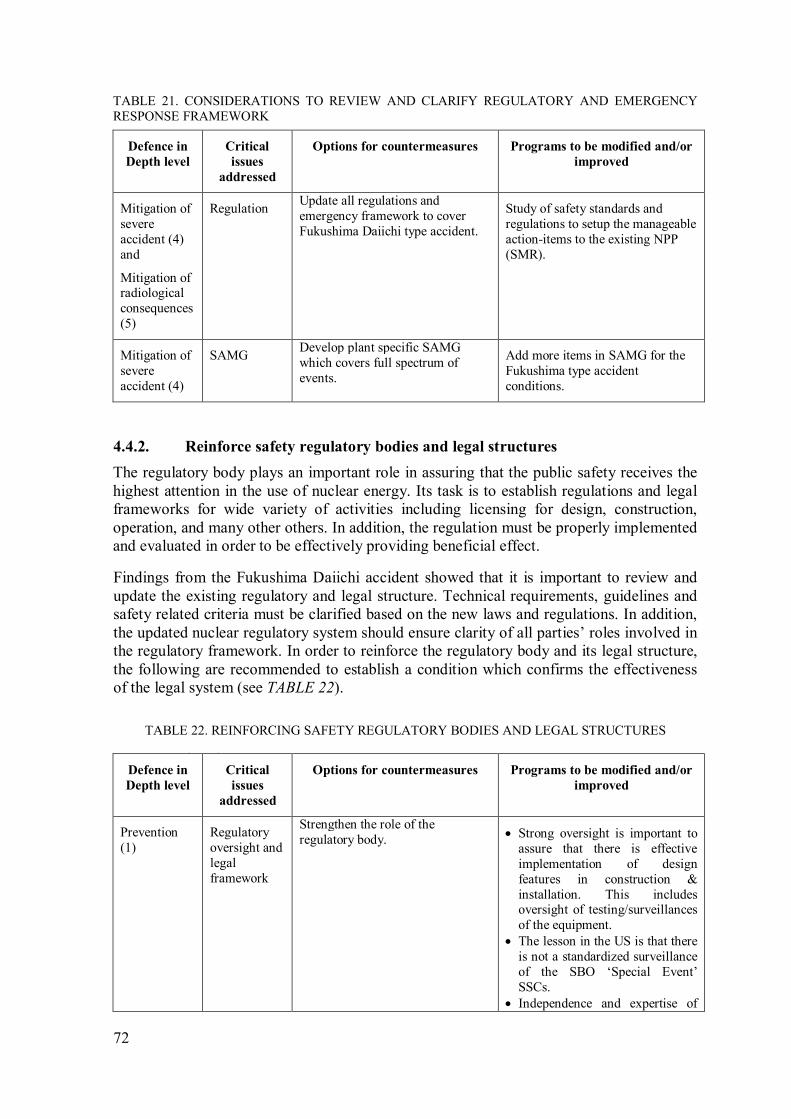
72
TABLE 21. CONSIDERATIONS TO REVIEW AND CLARIFY REGULATORY AND EMERGENCY
RESPONSE FRAMEWORK
Defence in
Depth level
Critical
issues
addressed
Options for countermeasures Programs to be modified and/or
improved
Mitigation of
severe
accident (4)
and
Mitigation of radiological
consequences
(5)
Regulation Update all regulations and
emergency framework to cover
Fukushima Daiichi type accident.
Study of safety standards and
regulations to setup the manageable
action-items to the existing NPP
(SMR).
Mitigation of
severe
accident (4)
SAMG Develop plant specific SAMG
which covers full spectrum of
events.
Add more items in SAMG for the
Fukushima type accident
conditions.
Reinforce safety regulatory bodies and legal structures 4.4.2.
The regulatory body plays an important role in assuring that the public safety receives the
highest attention in the use of nuclear energy. Its task is to establish regulations and legal
frameworks for wide variety of activities including licensing for design, construction,
operation, and many other others. In addition, the regulation must be properly implemented
and evaluated in order to be effectively providing beneficial effect.
Findings from the Fukushima Daiichi accident showed that it is important to review and
update the existing regulatory and legal structure. Technical requirements, guidelines and
safety related criteria must be clarified based on the new laws and regulations. In addition,
the updated nuclear regulatory system should ensure clarity of all parties’ roles involved in
the regulatory framework. In order to reinforce the regulatory body and its legal structure,
the following are recommended to establish a condition which confirms the effectiveness
of the legal system (see TABLE 22).
TABLE 22. REINFORCING SAFETY REGULATORY BODIES AND LEGAL STRUCTURES
TABLE 22 (cont.)
Defence in
Depth level
Critical
issues
addressed
Options for countermeasures Programs to be modified and/or
improved
Prevention
(1)
Regulatory
oversight and
legal
framework
Strengthen the role of the
regulatory body. • Strong oversight is important to
assure that there is effective
implementation of design
features in construction &
installation. This includes oversight of testing/surveillances
of the equipment.
• The lesson in the US is that there
is not a standardized surveillance
of the SBO ‘Special Event’
SSCs.
• Independence and expertise of
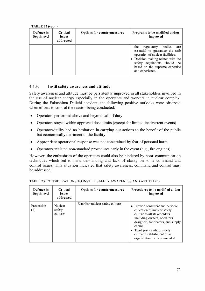
73
TABLE 22 (cont.)
Defence in
Depth level
Critical
issues
addressed
Options for countermeasures Programs to be modified and/or
improved
the regulatory bodies are
essential to guarantee the safe
operation of nuclear facilities.
• Decision making related with the
safety regulations should be
based on the supreme expertise
and experience.
Instil safety awareness and attitude 4.4.3.
Safety awareness and attitude must be persistently improved in all stakeholders involved in
the use of nuclear energy especially in the operators and workers in nuclear complex.
During the Fukushima Daiichi accident, the following positive outlooks were observed
when efforts to control the reactor being conducted:
• Operators performed above and beyond call of duty
• Operators stayed within approved dose limits (except for limited inadvertent events)
• Operators/utility had no hesitation in carrying out actions to the benefit of the public
but economically detriment to the facility
• Appropriate operational response was not constrained by fear of personal harm
• Operators initiated non-standard procedures early in the event (e.g., fire engines)
However, the enthusiasm of the operators could also be hindered by poor communication
techniques which led to misunderstanding and lack of clarity on some command and
control issues. This situation indicated that safety awareness, command and control must
be addressed.
TABLE 23. CONSIDERATIONS TO INSTILL SAFETY AWARENESS AND ATTITUDES
Defence in
Depth level
Critical
issues
addressed
Options for countermeasures Procedures to be modified and/or
improved
Prevention
(1)
Nuclear
safety
cultures
Establish nuclear safety culture • Provide consistent and periodic
education of nuclear safety
culture to all stakeholders
including owners, operators,
designers, fabricators, and supply
chains.
• Third party audit of safety
culture establishment of an
organization is recommended.

74
5. CONCLUDING REMARKS
New nuclear power plants, including SMRs, are to be designed, sited and constructed
consistent with the objective of preventing accidents in the commissioning and operation.
Should an accident occur, the plants shall be able to prevent and mitigate possible releases of
radionuclides that may cause long term off site contamination.
The Fukushima Daiichi accident unveiled many issues regarding weakness of existing plants
particularly regarding the design of ESF in withstanding extreme natural hazards and coping
with the challenging emergency situation that could include a simultaneous extended station
blackout. The study of accident progression and the lessons learned from this accident
recommended the need for NPPs to review and evaluate their ESF designs and sitings, as well
as to upgrade emergency preparedness and response, and nuclear safety infrastructure.
Accordingly, issues such as the magnitude of natural hazards, multiple reactor units on the
same site, common cause failures, hydrogen explosion, all on-site and off-site electric power
losses, emergency preparedness and procedures, safety culture and regulatory issues should be
addressed and documented in publication.
Many water cooled SMR designs and technologies are under development offering simplified
design and flexible deployment options. The issues and lessons learned from the Fukushima
Daiichi event are being incorporated into SMR design development. This publication attempts
to address concerns by providing technical considerations and options of countermeasures that
can be incorporated in water cooled SMRs.
The publication proposes considerations and examples to prevent the occurrence of cascading
severe accidents after extreme natural hazards. These proposals are useful for embarking
countries and utilities planning to deploy SMRs or advanced reactors. They are also useful for
SMR technology developers to enhance the performance of the ESF in their respective reactor
designs.
Various design concepts of ESF used by water cooled SMRs, which include the trip systems,
residual heat removal systems, safety injection systems and containment systems, were
discussed in this publication and they showed both similarities and differences in the
approaches to achieve enhanced safety. The features to deal with severe accident conditions
from different water cooled SMR designs were reviewed. However, this publication is not at
all intended to substitute design review, meant to determine whether the safety requirements
are being addressed in the design of water cooled SMR.
Water cooled SMR designs for near term deployment have variations in ESF designs that may
come from the reactor attributes such as design and safety characteristics, power level, and
type of safety system (active, passive or hybrid) to cope with accidents. They also have the
potentialities to duly adapt to and cope with a variety of extreme natural hazards (e.g.
Fukushima-like or simultaneous and multiple external hazards). This TECDOC presents and
discusses design safety considerations on appropriate and practical countermeasures to
incorporate and address the lessons learned from the Fukushima Daiichi accident to enhance
the design of engineered safety systems of water cooled SMRs currently under development.
Section 4 and the associated Tables in this TECDOC incorporate the details. The following is
a summary of the Tables.
• Possibility of simultaneous occurrence of extreme natural hazards, specific to the site
with appropriate return cycle (recurrence frequency) should be included in reactor
plant site analysis. Accordingly, a feasible degree of independence, with a practical

75
grace period, from off-site power, availability of cooling sources, communication and
transportation systems, etc., should be ensured in the design. (TABLE 6)
• Since some SMR designs incorporate multiple-units on the same site, some are
designed for deployment underground, barge–mounted (floating unit) or seabed–
anchored, which are first of its kind concepts, therefore, designers should consider
unprecedented and unexpected accident scenarios, including common cause failures to
provide countermeasures which can be carried out on the site if a meltdown occurs.
(TABLE 7)
• SMR designers should consider electrical power unavailability during extreme natural
hazards. The design should ensure core cooling and decay heat removal, e.g., by
ensuring survivability of power supply with on-site availability of portable equipment.
(TABLE 8)
• SMR designs should provide at least one success path in extreme natural hazards, to
cope with the accident to cool down the reactor core by passive, or active, or manually
aligned systems (such as portable pumps, heat removal systems and fire engines) or
suitable combination of these. (TABLE 9)
• SMR designs should prevent failure of safety related structures, systems and
components, or accommodate those failures with compensatory measures for all
extreme natural events. (TABLE 10)
o Water cooled SMRs offer specific features in safety related SSCs to assure
containment vessel integrity, diverse shutdown, core cooling and decay heat
removal. They include: reduced decay heat and reduced source term (due to small
size), the adoption of passive safety features (e.g. external cooling of containment
vessel with air or water or both, large amount of water per MW(th) (compared to
large reactors) and in-vessel core retention and cooling. (TABLE 10)
o Diverse cooling systems for containment and provision for connecting portable
cooling equipment should be provided to prevent primary containment vessel
(PCV) failure, e.g., by providing initial containment cooling by passive system(s)
followed by portable pump supplied water spray for long term service. (TABLE
10)
o Survivability of emergency power supply system should be assured to cope with
extreme natural hazards and extended SBO. SMRs should ensure a reasonable
grace period during which the essential safety functions can be restored. This can
be achieved by using passive safety features and high capacity compact batteries.
(TABLE 10)
• SMRs should avoid combustible mixture of hydrogen and oxygen inside and outside
the containment, by adopting re-combiners or inerting the containment. (TABLE 11)
• Containment vent system of SMR should be capable of preventing catastrophic failure
of containment by reducing pressure at appropriate rate. The venting system should
ensure full capability of filtering particulates to reduce off-site dose to the minimum.
(TABLE 12)
• SMR designs should ensure DC power availability for post accident monitoring
system even in case of extended SBO. The system and cables should be placed and
run in hardened and perforated housings to withstand severe accidents. (TABLE 13)
76
• SMR designs should ensure the integrity and leak tightness of spent fuel pool (SFP),
considering extreme natural hazards. Provision and facility for cooling water
replenishment and monitoring in emergency conditions should be taken into account
in the pool design. (TABLE 14)
• The design process of SMRs can take advantage of a risk-informed approach for safe
design that concurrently uses deterministic and probabilistic safety tools and analysis,
to provide robust and optimised safety features and eliminate cliff edge effects.
(TABLE 15).
• Requirement 42 of IAEA Safety Requirement – Safety Standards Series No. SSR–2/1
(Rev. 1) establishes the following requirements on safety analysis of the plant design.
“A safety analysis of the design for the nuclear power plant shall be conducted in
which methods of both deterministic analysis and probabilistic analysis shall be
applied to enable the challenges to safety in the various categories of plant states to be
evaluated and assessed”.
o Paragraph 5.70 requires that the design basis for items important to safety and
their links to initiating events and event sequences shall be confirmed on the basis
of a safety analysis.
o Paragraph 5.71 requires that it shall be demonstrated that the nuclear power
plant as designed is capable of complying with authorized limits on discharges
with regard to radioactive releases and with the dose limits in all operational
states, and is capable of meeting acceptable limits for accident conditions.
o Paragraph 5.72 requires that the safety analysis shall provide assurance that
defence in depth has been implemented in the design of the plant.
o Paragraph 5.73 requires that the safety analysis shall provide assurance that
uncertainties have been given adequate consideration in the design of the plant
and especially that adequate margins are available to avoid cliff edge effects and
large or early radioactive releases.
o Paragraph 5.74 requires that the applicability of the analytical assumptions,
methods and degree of conservatism used in the design of the plant shall be
updated and verified for the current or as built design.
o Paragraph 5.76 requires that the design shall take due account of the
probabilistic safety analysis of the plant for all modes of operation and for all
plant states, including shutdown, with particular reference to:
a) Establishing that a balanced design has been achieved such that no
particular feature or postulated initiating event makes a
disproportionately large or significantly uncertain contribution to the
overall risks, and that, to the extent practicable, the levels of defence in
depth are independent;
b) Providing assurance that small deviation in plant parameters that could
give rise to large variations in plant conditions (cliff edge effects) will be
prevented;
c) Comparing the results of the analysis with the acceptance criteria for risk
where these have been specified.
• Plant operators, utility management and governmental support organizations should
coordinate and prepare for extreme emergencies by establishing improved command
77
and communication chains and support logistics, hold periodic exercises and drills,
and storing backup equipment, on-site and off-site, supported with periodic inspection
as for other safety systems. (TABLE 16 and TABLE 18)
• Provide design solutions for a grace period of seven or more days, without operator
intervention. In addition, operator training for SAMGs should be provided, including
analysis of multiple unit plants scenarios where needed. (TABLE 17)
• National team for severe accident management shall be established for nuclear power
plants, including SMRs. Technical support team should be established consisting of
designers and operators for decision making for severe accident counter-actions under
harsh environment. More communication and education on emergency preparedness
are necessary to ensure public awareness of emergency situation. (TABLE 19)
• Procedure and plans should be in place to bring equipment from adjacent SMR units
or other power plants. Reciprocal support from international community should be
established through formal agreements for emergency equipment and expert
assistance. A regional resource centre should also be established. (TABLE 20)
• Water cooled SMRs could be first-of-a-kind, hence plant specific SAMG which cover
full spectrum of events shall be developed by incorporating means to cope with
extreme natural events. (TABLE 21)
• The role of the regulatory body should be reinforced. Particularly for embarking
countries, independence and expertise of the regulatory bodies is essential to guarantee
the safe operation of nuclear facilities, including SMRs. (TABLE 22)
• Establishing nuclear safety culture that incorporates lessons learned from the
Fukushima Daiichi type accident is essential. Consistent and periodic education on
nuclear safety culture to all stakeholders including owners, operators, designers,
fabricators, and supply chains, should be provided. (TABLE 23)
It is also commented that there will be a need of IAEA role in SMR design safety review to
provide advice regarding the design’s ability to meet the IAEA Fundamental Safety
Principles. It is also suggested that the IAEA should develop relevant safety standards to
incorporate SMR specific design features and special condition, as the current safety
standards are applicable primarily for land based stationary nuclear power plants with
water cooled reactors designed for electricity generation.


79
REFERENCES
[1] INTERNATIONAL ATOMIC ENERGY AGENCY, The Fukushima Daiichi
Accident, Report by the IAEA Director General, IAEA, Vienna (2015).
[2] INTERNATIONAL ATOMIC ENERGY AGENCY, Action Plan on Nuclear
Safety, IAEA General Conference, Vienna (2011).
[3] Yamada, K., Lessons Learned from the Fukushima Accident to Apply to Water
Cooled Reactor Technology Development, CM on Preparation of Toolkit for
SMR Technology Assessment on the Reliability of Engineered Safety Features,
IAEA, Vienna, (2012).
[4] Lee, J.C., and McCormick, N.J., Risk and Safety Analysis on Nuclear System,
John Wiley and Sons (2011).
[5] TEPCO, Fukushima Nuclear Accident Analysis Report (interim Report), the
Tokyo Electric Power Company, Inc., Japan (2011).
[6] INPO, Special Report on the Nuclear Accident at the Fukushima Daiichi Nuclear
Power Station, the Institute of Nuclear Power Operations (2011).
[7] INTERNATIONAL ATOMIC ENERGY AGENCY, Design of Reactor
Containment Systems for Nuclear Power Plants, IAEA, Vienna (2004).
[8] Areva, Schemata of EPR's Core-catcher, 2006 [cited 2014 June],
http://commons.wikimedia.org/wiki/File:Schemata_core_catcher_EPR.jpg
[9] Corporation, C.W., Passive Autocatalytic Recombiner (PAR) - Preventing
Hydrogen Buildup (2014),
http://enertech.cwfc.com/brandProducts/spokes/10a_CanduEnergy.htm
[10] INTERNATIONAL ATOMIC ENERGY AGENCY, Design Features to Achieve
Defence in Depth in Small and Medium Sized Reactors, IAEA Nuclear Energy
Series NP-T-2.2, IAEA, Vienna (2009).
[11] INTERNATIONAL ATOMIC ENERGY AGENCY, Defence In Depth In
Nuclear Safety, INSAG-10, IAEA, Vienna (1996).
[12] Sekimura, N., The Accident in Fukushima Daiichi Nuclear Power Plant, Causes
and Emergency Actions, IAEA Nuclear Energy Management School, IAEA
Tokai, Japan (2012).
[13] INTERNATIONAL ATOMIC ENERGY AGENCY, International Fact Finding
Expert Mission of the Fukushima Daiichi NPP Accident Following the Great East
Japan Earthquake and Tsunami, IAEA, Vienna (2011).
[14] Report of Japanese Government to IAEA Ministerial Conference on Nuclear
Safety - Accident at TEPCO's Fukushima Nuclear Power Stations, Japan (2014),
http://www.iaea.org/newscenter/focus/fukushima/japan-report/.
[15] Charles Miller, A. C., Daniel Dorman, Jack Grobe, Gary Holahan, Nathan
Sanfilippo, Recommendations for enhancing reactor safety in the 21st century:
The Near-term Task Force review of insights from the Fukushima Daiichi
accident, US NRC (2011).
[16] Weightman, M., Japanese earthquake and tsunami: Implications for the UK
nuclear industry (HM Chief Inspector’s Final Fukushima Report), Office for
Nuclear Regulation, UK (2011).
[17] Hitachi_GE, Advanced Boiling Water Reactor The only generation Ⅲ+ Reactor
in Operation today, Hitachi_GE Nuclear Energy Ltd., Japan (2013).

80
[18] Loflin, L.I., Incorporation of Fukushima Lessons Learned into Small Modular
Light Water Reactor Functional Requirements, ASME Small Modular Reactor
Symposium, Washington DC, (2014).
[19] US Nuclear Regulatory Commission, Boiling Water Reactor GE BWR/4
Technology Advanced Manual (2002).
[20] US Nuclear Regulatory Commission, BWR/4 Technology Manual (R-104B),
USNRC Technical Training Center, USA (2002).
[21] Aritomi, M., Possible Countermeasures, in Consultant Meeting on Incorporating
Lessons Learned from the Fukushima Accident in SMR technology Assessment
for Design of engineered safety system, IAEA, Vienna (2012).
[22] INTERNATIONAL ATOMIC ENERGY AGENCY, Preliminary Lessons
Learned from the Fukushima Daiichi Accident for Advanced Nuclear Power Plant
Technology Development - NTR Supplement, IAEA 57th
General Conference,
Vienna, (2013).
[23] Yamada, K., and Harper ,M.J., Technical lessons Learned from the Fukushima
Accident and Water Cooled Reactor Technologies to Cope with Fukushima-type
accidents, ICAAP, Charlotte, USA (2014).
[24] Lyubarskiy, A., Kuzmina, I., and El-shanawany, M., Notes on Potential Areas for
Enhancement of the PSA Methodology based on Lessons Learned from the
Fukushima Accident (2012).
[25] Yasuda, K., Accident Management on Fukushima Accident Management on
Fukushima, 5th INPRO Dialogue Forum on Global Nuclear Energy Sustainability,
COEX, Seoul, Republic of Korea (2012).
[26] GE_Hitachi, ABWR Plant General Description, GE Hitachi Nuclear Energy: USA
(2007).
[27] The ESBWR Plant General Description, 2011.
[28] Westinghouse, AP1000 Design Control Document : Engineered Safety Features
(2011).
[29] INTERNATIONAL ATOMIC ENERGY AGENCY, Status report 81 - Advanced
Passive PWR (AP 1000), IAEA, Vienna (2011).
[30] INTERNATIONAL ATOMIC ENERGY AGENCY, Status report 99 - ATMEA1
(ATMEA1), IAEA, Vienna (2011).
[31] Tabuchi, K., et al., Concepts and Features of ATMEA1 as the latest 1100 MW(e)-
class 3-Loop PWR Plant, Mitsubishi Heavy Industries Technical Review, Vol.
46(No. 4), (2009).
[32] ATMEA, ATMEA1 – The mid-sized Generation III+ PWR you can rely on, in
Conference ETE2009, Siófok – Hungary (2009).
[33] The mid-sized generation III+ PWR you can rely on, (2008),
http://www.atmeasas.com/scripts/ATMEA/publigen/content/templates/Show.asp?
P=57&L=EN.
[34] Zanocco, P., and Gimenez, M., CAREM Technical Aspect, Project and Licensing
Satus, in Technical Meeting/Workshop on Technology Assessment of Small and
Medium-sized Reactors (SMRs) for Near Term Deployment., Vienna, (2011).
[35] INTERNATIONAL ATOMIC ENERGY AGENCY, Status of innovative small
and medium sized reactor designs , Reactors with conventional refueling scheme,
in IAEA-TECDOC-14852006, IAEA, Vienna (2005).
[36] Lee, W.J., The SMART Reactor, 4th
Annual Asian-Pacific Nuclear Energy Forum,
University of California, Berkeley, California (2010).
[37] INTERNATIONAL ATOMIC ENERGY AGENCY, Status report 77 - System-
Integrated Modular Advanced Reactor (SMART), IAEA, Vienna (2011).

81
[38] Carelli, M.D., IRIS – International Reactor Inovative and Secure (final technical
progress report), Department of Energy, USA (2003).
[39] Carelli, M.D., IRIS: A global approach to nuclear power renaissance, Nuclear
News, 46(10), (2003) p. 32 – 42.
[40] Halfinger, J.A., and Haggerty, M.D., The B&W mPOWER Scalable Practical
Nuclear Reactor Design, Nuclear Technology, 178(May 2012), p. 164-169 (2012).
[41] Colbert, C., Overview of NuScale Design, in Technical Meeting on Technology
Assessment of SMRs for Near-Term Deployment , Chengdu, China (2013).
[42] INTERNATIONAL ATOMIC ENERGY AGENCY, NuScale Power Modular and
Scalable Reactor, IAEA, Vienna (2013).
[43] NuScale, NuScale Plant Design Overview (2012).
[44] INTERNATIONAL ATOMIC ENERGY AGENCY, Advances in Small Modular
Reactor Designs Developments – A supplement to: IAEA Advanced Reactors
Information System (ARIS), IAEA, Vienna (2014).
[45] Harkness, A.W., Westinghouse Small Modular Reactor, ASME Press (2013).
[46] Smith, M.C., and Wright, R.F., Westinghouse Small Modular ReactorPassive
Safety System Response to Postulated Events, ICAPP'12, Chicago, USA (2012).
[47] Lessons Learned from the Nuclear Accident at the Fukushima Daiichi Nuclear
Power Station, Revision 0, Special Report, INPO 11-005 Addendum (2012).


83
DEFINITIONS OF TERMS
Engineered safety
features
Features of the third level in defence in depth to control
postulated incidents or accidents in order to prevent them
from progressing to severe accidents or to mitigate their
consequences, as appropriate.
Small modular
reactor
Advanced nuclear reactors with electric power of up to 300
MW(e), built as modules in a factory setting then shipped to
sites as demand arises, aiming for the economy of multiple by
shortening construction schedule.
Extreme natural
hazards
Extreme events unconnected with the operation of a facility
or the conduct of an activity that could have an effect on the
safety of the facility or activity. Typical examples of natural
hazards for nuclear facilities include earthquakes, tornadoes,
and tsunamis.
Integral PWR A type of water cooled SMR adopting the principle of
pressurized water reactor that integrates the components
within the reactor coolant system, such as steam generators
and pressurizer to be within the reactor pressure vessel, i.e., in
the same compartment with the core assembly and eliminates
the need of large bore piping network, with the objective to
enable modularization and enhance safety performance.
Cliff edge effect In a nuclear power plant, an instance of severely abnormal
plant behaviour caused by an abrupt transition from one plant
status to another following a small deviation in a plant
parameter, and thus a sudden large variation in plant
conditions in response to a small variation in an input.
Design basis accident Accident conditions against which a facility is designed
according to established design criteria, and for which the
damage to the fuel and the release of radioactive material are
kept within authorized limits.
Severe accident Accident conditions more severe than a design basis accident
and involving significant core degradation.
84
Isolation condenser
system
The IC system transfers residual and decay heat from the
reactor coolant to the water in the shell side of the heat
exchanger resulting in steam generation. The steam generated
in the shell side of the heat exchanger is then vented to the
outside atmosphere. The system employs natural circulation
as the driving head from the reactor steam side, through the
IC tubes, and back to the reactor.
The IC system is automatically initiated if a high reactor
pressure condition is sustained for 15 seconds. The time delay
prevents unnecessary system initiation during turbine trips.
Also at most plants, the IC system automatically initiates on a
low vessel water level to aid in reducing reactor pressure for
small line breaks. The IC system is designed to provide core
cooling regardless of whether electrical power is available.
Reactor core isolation
cooling system
The RCIC system is a steam-driven single train standby
system for safe shut down of the plant. The system is not
considered part of the emergency core cooling system
(ECCS), and does not have a loss of coolant accident (LOCA)
function. The RCIC system is designed to ensure that
sufficient reactor water inventory is maintained in the vessel
to permit adequate core cooling. This prevents the reactor fuel
from overheating in the event that the reactor is isolated from
the secondary plant.
Residual heat removal
system
The RHR system is designed to remove residual heat from the
reactor core after shutdown, and during and after appropriate
operational states and accident conditions.
Hardened
Containment vent
A reliable, hardened vent that can remove heat and pressure
before potential damage to a reactor core occurs. This not
only helps preserve the integrity of the containment building,
but can also help delay reactor core damage or melting.
Defence in depth A hierarchical deployment of different levels of diverse
equipment and procedures to prevent the escalation of
anticipated operational occurrences and to maintain the
effectiveness of physical barriers placed between a radiation
source or radioactive material and workers, members of the
public or the environment, in operational states and, for some
barriers, in accident conditions.
The objectives of defence in depth are:
(a) To compensate for potential human and component
85
failures;
(b) To maintain the effectiveness of the barriers by averting
damage to the facility and to the barriers themselves;
(c) To protect workers, members of the public and the
environment from harm in accident conditions in the event
that these barriers are not fully effective.
INSAG defines five levels of defence in depth:
(a) Level 1: Prevention of abnormal operation and failures.
(b) Level 2: Control of abnormal operation and detection of
failures.
(c) Level 3: Control of accidents within the design basis.
(d) Level 4: Control of severe plant conditions, including
prevention of accident progression and mitigation of the
consequences of severe accidents.
Risk-informed
approach
A “risk-informed” approach to regulatory decision making
represents a philosophy whereby risk insights are considered
together with other factors to establish requirements that
better focus licensee and regulatory attention on design and
operational issues commensurate with their importance to
health and safety.
Grace period The period of time during which a safety function is ensured
in an event with no necessity for action by personnel. Typical
grace periods range from 20 min to 12 hrs. The period of
grace may be achieved by means of the automation of
actuations, the adoption of passive systems or the inherent
characteristics of a material (such as the heat capacity of the
containment structure), or by any combination of these.
Ultimate heatsink A medium into which the transferred residual heat can always
be accepted, even if all other means of removing the heat
have been lost or are insufficient. This medium is normally a
body of water or the atmosphere.
Accident management The taking of a set of actions during the evolution of a
beyond design basis accident:
a) To prevent the escalation of the event into a severe
accident;
b) To mitigate the consequences of a severe accident;
86
c) To achieve a long term safe stable state.
The second aspect of accident management (to mitigate the
consequences of a severe accident) is also termed severe
accident management.
Passive autocatalytic
recombiner
In the unlikely event of a LOCA, large amounts of hydrogen
could release in the reactor containment, leading to a high
concentration of explosive gas which might ultimately affect
the integrity of the containment. Passive Autocatalytic
Recombiner (PAR) is a hydrogen reduction system. This
advanced safety system requires neither operator action nor a
power supply. Based on the principle of catalytic oxidization,
the PAR features a gas treating capacity of up to 1500 m3/h
per unit. The hydrogen concentration can then be kept below
explosive limits — even under severe accident conditions.
Emergency
preparedness
The capability to take actions that will effectively mitigate the
consequences of an emergency for human health and safety,
quality of life, property and the environment.
Automatic
depressurization
system
System to depressurize the reactor (and keeps it
depressurized) to allow emergency core injection system or
other low pressure refill.
Primary containment
vessel
The primary vessel as method or physical structure designed
to prevent or control the release and the dispersion of
radioactive substances.
Although related to confinement, containment is normally
used to refer to methods or structures that perform a
confinement function, namely preventing or controlling the
release of radioactive substances and their dispersion in the
environment.
87
ABBREVIATIONS
ACS Atmospheric Control System
ADS Automatic Depressurization System
AM Accident Management
BDB Beyond Design Basis
BWR Boiling Water Reactor
CCF Common Cause Failure
CDF Core Damage Frequency
CMT Core Make-up Tank
COPS Containment Overpressure Protection System
CRDM Control Rod Drive Mechanism
CSS Core Spray System
CST Condensate Storage Tank
CV Containment Vessel
DB Design Basis
DBA Design Basis Accident
DC Direct Current
DG Diesel Generator
DiD Defence in Depth
DHRS Decay Heat Removal System
DVI Direct Vessel Injection
ECCS Emergency Core Cooling System
EBS Extra Borating System
EDG Emergency Diesel Generator
EDMG Extensive Damage Mitigation Guidelines
EHRS Emergency Heat Removal System
EOP Emergency Operating Procedure
EPG Emergency Procedure Guidelines
ESF Engineered Safety Feature
FA Fuel Assembly

88
FDA Fukushima Daiichi Accident
FMCRD Fine Motion Control Rod Drive
FWIV Feed Water Isolation Valve
GDCS Gravity Driven Cooling System
HPCF High Pressure Core Flooder
HPCI High Pressure Coolant Injection
HPCS High Pressure Core Spray
HVAC Heating, Ventilating, and Air Conditioning
HX Heat Exchanger
IC Isolation Condenser
IRWST In-containment Refuelling Water Storage Tank
LERF Large Early Release Frequency
LOCA Loss of Coolant Accident
LPCI Low Pressure Coolant Injection
LPFL Low Pressure Flooder Mode
MCC Motor Control Center
MSIV Main Steam Isolation Valve
NPP Nuclear Power Plant
NSSS Nuclear Steam Supply System
PAR Passive Autocatalytic Re-combiner
PCV Primary Containment Vessel
PCCS Passive Containment Cooling System
PSA Probabilistic Safety Assessment
PRHR Passive Residual Heat Removal
PWR Pressurized Water Reactor
PXS Passive Core Cooling System
RCIC Reactor Core Isolation Cooling
RCS Reactor Cooling System
RHRS Residual Heat Removal System
RPS Reactor Protection System
RPV Reactor Pressure Vessel

89
RV Reactor Vessel
SAMG Severe Accident Management Guideline
SBO Station Blackout
SCS Shutdown Cooling System
SFP Spent Fuel Pool
SG Steam Generator
SGTS Standby Gas Treatment System
SIS Safety Injection System
SLC Standby Liquid Control
SMR Small and Medium Sized Reactor or Small Modular Reactor
SRV Safety Relieve Valve
SSC Structures, Systems and Components
TAF Top of Active Fuel
UHS Ultimate Heat Sink

91
ANNEX I
Technical overview of Engineered Safety Features of water cooled reactors
I.1. Boiling water reactors (BWRs)
I.1.1. GE BWR/4
The BWR reactor is the second most common type of reactor used for electricity
generation. The reactor core is cooled by water, which boils and turns into steam in the
upper part of the core. After passing through moisture separator and dryer, the steam is
directed to a turbine to rotate electric generator. The first BWR was developed by the
Idaho National Laboratory and General Electric in the mid-1950s. Since then, incremental
development of features has been conducted covering modification of containment design,
steam-dryer, general layout of the reactor building, reactor control and safety system and
elimination of heat exchanger. One of BWR series is the BWR/4 which is one of the units
suffered from tsunami and flooding in the Fukushima Daiichi nuclear complex.
The BWR/4 steam supply system mainly consists of a reactor pressure vessel – which
contains the core, steam dryer and separator– that is connected to pipes to allow re-
circulation pumps to circulate the coolant water inside the vessel. In addition, a set of
control and safety systems to ensure safe operation and a containment system which is
intended as barrier for radioactive release during accident and as protection against
external hazards are provided. The safety system is made up of redundant and multiple
equipment to guarantee the intended functions. Some of their functionalities are to provide
emergency core cooling, to control and maintain containment’s pressure and temperature
below its design limit, and to provide additional control for core reactivity. In BWR/4 the
emergency core cooling function is facilitated by the low pressure coolant injection (LPCI)
mode of residual heat removal (RHR) system, RCIC system, HPCI system, automatic
depressurization system (ADS), and core spray system (CS) as can be seen in FIG. I-1.
Meanwhile the other two functions are provided by the containment spray system (CSS)
and standby liquid control (SLC) system.
FIG. I-1. BWR/4 emergency core cooling system [20].
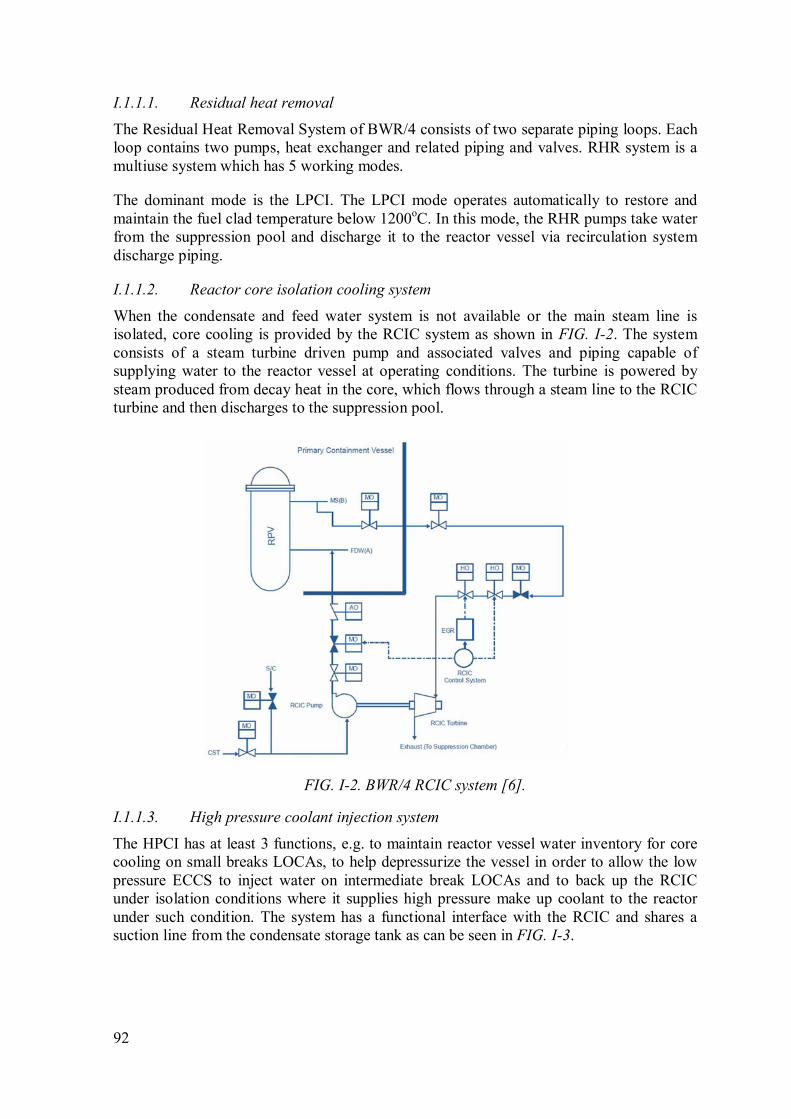
92
I.1.1.1. Residual heat removal
The Residual Heat Removal System of BWR/4 consists of two separate piping loops. Each
loop contains two pumps, heat exchanger and related piping and valves. RHR system is a
multiuse system which has 5 working modes.
The dominant mode is the LPCI. The LPCI mode operates automatically to restore and
maintain the fuel clad temperature below 1200oC. In this mode, the RHR pumps take water
from the suppression pool and discharge it to the reactor vessel via recirculation system
discharge piping.
I.1.1.2. Reactor core isolation cooling system
When the condensate and feed water system is not available or the main steam line is
isolated, core cooling is provided by the RCIC system as shown in FIG. I-2. The system
consists of a steam turbine driven pump and associated valves and piping capable of
supplying water to the reactor vessel at operating conditions. The turbine is powered by
steam produced from decay heat in the core, which flows through a steam line to the RCIC
turbine and then discharges to the suppression pool.
FIG. I-2. BWR/4 RCIC system [6].
I.1.1.3. High pressure coolant injection system
The HPCI has at least 3 functions, e.g. to maintain reactor vessel water inventory for core
cooling on small breaks LOCAs, to help depressurize the vessel in order to allow the low
pressure ECCS to inject water on intermediate break LOCAs and to back up the RCIC
under isolation conditions where it supplies high pressure make up coolant to the reactor
under such condition. The system has a functional interface with the RCIC and shares a
suction line from the condensate storage tank as can be seen in FIG. I-3.

93
FIG. I-3. HPCI system of BWR/4.
I.1.1.4. Automatic depressurization system
The role of ADS is to depressurize the reactor vessel during a small break LOCA. It
consists of automatically activated pressure relief valves. When the valves are opening, the
pressure inside vessel decreases to a level which permits water injection from the low
pressure core spray system to the core.
I.1.1.5. Core spray system
The main purpose of the core spray system (CS) is to provide a low pressure spray cooling
to the reactor core under LOCA conditions. There are two independent pumping loops of
CS, each consists of a set of spray nozzles located on independent ring spargers put within
the core shroud above the fuel assembly (FA). The nozzles are arranged to provide uniform
coolant flow to the fuel assemblies. The system provides enough cooling water and can be
powered by emergency power system. The schematic diagram of CS is shown in FIG. I-4.
FIG. I-4. BWR/4 core spray system [20].

94
I.1.2. GE BWR/5
BWR/5 is one of the units built in the Fukushima Daiichi nuclear complex (Unit 6). This
reactor was in outage period when the complex was struck by large tsunami wave. As the
reactor location is higher than others, this reactor was not challenged as hard as the other
three units being in operation at that time.
For dealing with the design basis accident (DBA), the safety feature of this reactor is
provided by emergency core cooling system as shown in FIG. I-5, which consists of high
pressure core spray system (HPCF), ADS, low pressure core spray system (LPCS), and
LPCI mode of residual heat removal [19]. These systems are elaborated in more detail in
the following.
FIG. I-5. ECCS of BWR/5 with Mark II containment [19].
A.1.2.1 High pressure core spray (HPCS) system
The HPCS system is a single loop system consisting of a suction shutoff valve, one motor
drive pump, discharge check valve, motor operated injection valve, minimum flow valve,
full flow test valve to the suppression pool, two high pressure flow test valves to the
condensate storage tank, discharge sparger and associated piping and instrumentation. It is
designed to provide high pressure emergency core cooling following small, medium or
large line breaks. The system takes water from the condensate storage tank or suppression
pool and delivers the water to the sparger positioned on the upper core shroud. The HPCS
pump starts automatically on high pressure in the drywell signal or on the low water level-
2 in the reactor vessel. Power for this system comes from a standby power system diesel
generator.
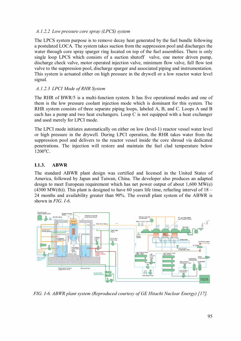
95
A.1.2.2 Low pressure core spray (LPCS) system
The LPCS system purpose is to remove decay heat generated by the fuel bundle following
a postulated LOCA. The system takes suction from the suppression pool and discharges the
water through core spray sparger ring located on top of the fuel assemblies. There is only
single loop LPCS which consists of a suction shutoff valve, one motor driven pump,
discharge check valve, motor operated injection valve, minimum flow valve, full flow test
valve to the suppression pool, discharge sparger and associated piping and instrumentation.
This system is actuated either on high pressure in the drywell or a low reactor water level
signal.
A.1.2.3 LPCI Mode of RHR System
The RHR of BWR/5 is a multi-function system. It has five operational modes and one of
them is the low pressure coolant injection mode which is dominant for this system. The
RHR system consists of three separate piping loops, labeled A, B, and C. Loops A and B
each has a pump and two heat exchangers. Loop C is not equipped with a heat exchanger
and used merely for LPCI mode.
The LPCI mode initiates automatically on either on low (level-1) reactor vessel water level
or high pressure in the drywell. During LPCI operation, the RHR takes water from the
suppression pool and delivers to the reactor vessel inside the core shroud via dedicated
penetrations. The injection will restore and maintain the fuel clad temperature below
1200oC.
I.1.3. ABWR
The standard ABWR plant design was certified and licensed in the United States of
America, followed by Japan and Taiwan, China. The developer also produces an adapted
design to meet European requirement which has net power output of about 1,600 MW(e)
(4300 MW(th)). This plant is designed to have 60 years life time, refueling interval of 18 –
24 months and availability greater than 90%. The overall plant system of the ABWR is
shown in FIG. I-6.
FIG. I-6. ABWR plant system (Reproduced courtesy of GE Hitachi Nuclear Energy) [17].
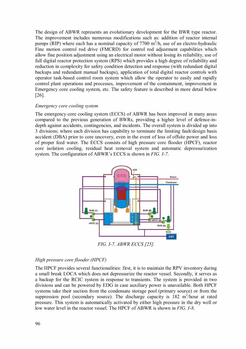
96
The design of ABWR represents an evolutionary development for the BWR type reactor.
The improvement includes numerous modifications such as: addition of reactor internal
pumps (RIP) where each has a nominal capacity of 7700 m3/h, use of an electro-hydraulic
Fine motion control rod drive (FMCRD) for control rod adjustment capabilities which
allow fine position adjustment using an electrical motor without losing its reliability, use of
full digital reactor protection system (RPS) which provides a high degree of reliability and
reduction in complexity for safety condition detection and response (with redundant digital
backups and redundant manual backups), application of total digital reactor controls with
operator task-based control room system which allow the operator to easily and rapidly
control plant operations and processes, improvement of the containment, improvement in
Emergency core cooling system, etc. The safety feature is described in more detail below
[26].
Emergency core cooling system
The emergency core cooling system (ECCS) of ABWR has been improved in many areas
compared to the previous generation of BWRs, providing a higher level of defence-in-
depth against accidents, contingencies, and incidents. The overall system is divided up into
3 divisions; where each division has capability to terminate the limiting fault/design basis
accident (DBA) prior to core uncovery, even in the event of loss of offsite power and loss
of proper feed water. The ECCS consists of high pressure core flooder (HPCF), reactor
core isolation cooling, residual heat removal system and automatic depressurization
system. The configuration of ABWR’s ECCS is shown in FIG. I-7.
FIG. I-7. ABWR ECCS [25].
High pressure core flooder (HPCF)
The HPCF provides several functionalities: first, it is to maintain the RPV inventory during
a small break LOCA which does not depressurize the reactor vessel. Secondly, it serves as
a backup for the RCIC system in response to transients. The system is provided in two
divisions and can be powered by EDG in case auxiliary power is unavailable. Both HPCF
systems take their suction from the condensate storage pool (primary source) or from the
suppression pool (secondary source). The discharge capacity is 182 m3/hour at rated
pressure. This system is automatically activated by either high pressure in the dry well or
low water level in the reactor vessel. The HPCF of ABWR is shown in FIG. I-8.
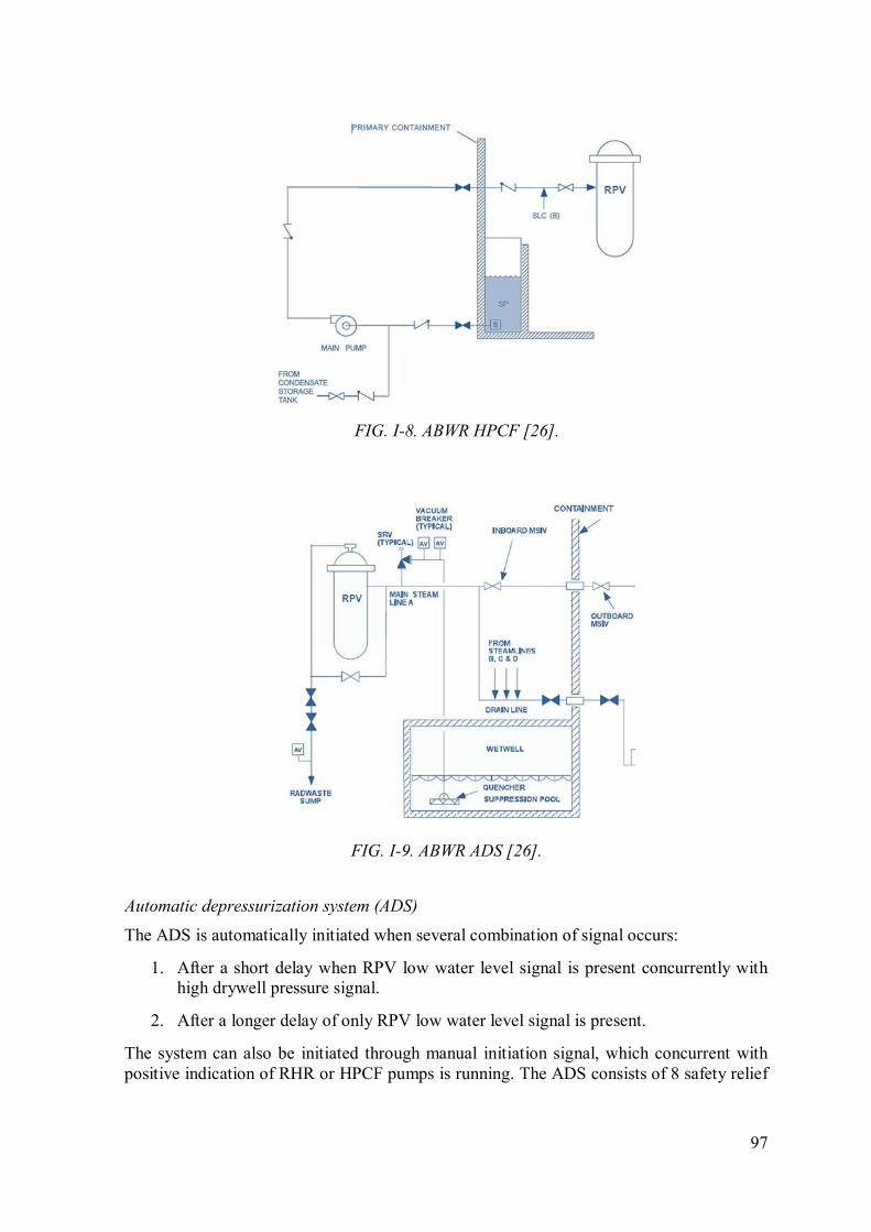
97
FIG. I-8. ABWR HPCF [26].
FIG. I-9. ABWR ADS [26].
Automatic depressurization system (ADS)
The ADS is automatically initiated when several combination of signal occurs:
1. After a short delay when RPV low water level signal is present concurrently with
high drywell pressure signal.
2. After a longer delay of only RPV low water level signal is present.
The system can also be initiated through manual initiation signal, which concurrent with
positive indication of RHR or HPCF pumps is running. The ADS consists of 8 safety relief
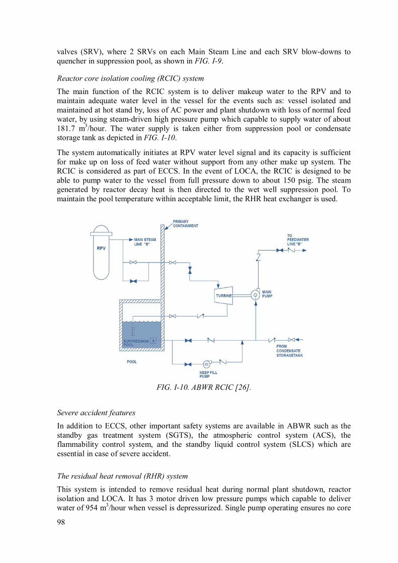
98
valves (SRV), where 2 SRVs on each Main Steam Line and each SRV blow-downs to
quencher in suppression pool, as shown in FIG. I-9.
Reactor core isolation cooling (RCIC) system
The main function of the RCIC system is to deliver makeup water to the RPV and to
maintain adequate water level in the vessel for the events such as: vessel isolated and
maintained at hot stand by, loss of AC power and plant shutdown with loss of normal feed
water, by using steam-driven high pressure pump which capable to supply water of about
181.7 m3/hour. The water supply is taken either from suppression pool or condensate
storage tank as depicted in FIG. I-10.
The system automatically initiates at RPV water level signal and its capacity is sufficient
for make up on loss of feed water without support from any other make up system. The
RCIC is considered as part of ECCS. In the event of LOCA, the RCIC is designed to be
able to pump water to the vessel from full pressure down to about 150 psig. The steam
generated by reactor decay heat is then directed to the wet well suppression pool. To
maintain the pool temperature within acceptable limit, the RHR heat exchanger is used.
FIG. I-10. ABWR RCIC [26].
Severe accident features
In addition to ECCS, other important safety systems are available in ABWR such as the
standby gas treatment system (SGTS), the atmospheric control system (ACS), the
flammability control system, and the standby liquid control system (SLCS) which are
essential in case of severe accident.
The residual heat removal (RHR) system
This system is intended to remove residual heat during normal plant shutdown, reactor
isolation and LOCA. It has 3 motor driven low pressure pumps which capable to deliver
water of 954 m3/hour when vessel is depressurized. Single pump operating ensures no core

99
damage. The RHR system has six working modes, each with specifics purposes, as shown
in FIG. I-11.
Safety-related modes:
1. Low pressure flooder system (LPFL) consists of 3 individual loops which provide
water supply for core cooling to compensate the water loss due to any cause including
LOCA. This mode is automatically initiated by a low water level in reactor vessel or
high pressure in the drywell (LOCA signal) or can also be manually actuated.
2. Suppression pool water cooling mode consists of 3 individual loops which
automatically initiates on high suppression pool temperature. During normal state, this
mode cools the pool below 49°C. The water is taken from suppression pool, and then
the flow goes to the heat exchanger and is returned to the pool again. The mode can
also be manually actuated.
3. Primary containment vessel spray cooling mode (consists of 2 loops). When manually
actuated, this mode sprays the water from suppression chamber pool into drywell and
wet well. The sprayed water (which becomes hot) will return to the suppression
chamber through vent pipes after the drywell water level reach the pipe level. When the
hot water from the dry well reaches the suppression pool it increases the pool
temperature which is then cooled by the RHR system heat exchanger before used for
spraying again.
FIG. I-11. ABWR RHR [26].
Non – safety:
4. Reactor shutdown cooling mode
This mode is to allow refuelling activities and equipment maintenance. In this mode, the
RHR system cools down the reactor coolant below 60°C within 20 hours after the
shutdown. The suction is taken from the RPV and the flow goes to the RHR heat
exchanger and returned to the RPV via LPFL injection lines.
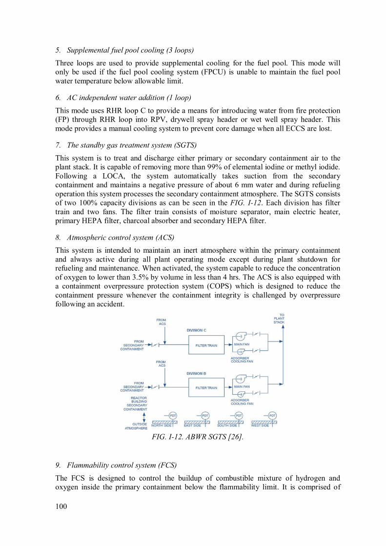
100
5. Supplemental fuel pool cooling (3 loops)
Three loops are used to provide supplemental cooling for the fuel pool. This mode will
only be used if the fuel pool cooling system (FPCU) is unable to maintain the fuel pool
water temperature below allowable limit.
6. AC independent water addition (1 loop)
This mode uses RHR loop C to provide a means for introducing water from fire protection
(FP) through RHR loop into RPV, drywell spray header or wet well spray header. This
mode provides a manual cooling system to prevent core damage when all ECCS are lost.
7. The standby gas treatment system (SGTS)
This system is to treat and discharge either primary or secondary containment air to the
plant stack. It is capable of removing more than 99% of elemental iodine or methyl iodide.
Following a LOCA, the system automatically takes suction from the secondary
containment and maintains a negative pressure of about 6 mm water and during refueling
operation this system processes the secondary containment atmosphere. The SGTS consists
of two 100% capacity divisions as can be seen in the FIG. I-12. Each division has filter
train and two fans. The filter train consists of moisture separator, main electric heater,
primary HEPA filter, charcoal absorber and secondary HEPA filter.
8. Atmospheric control system (ACS)
This system is intended to maintain an inert atmosphere within the primary containment
and always active during all plant operating mode except during plant shutdown for
refueling and maintenance. When activated, the system capable to reduce the concentration
of oxygen to lower than 3.5% by volume in less than 4 hrs. The ACS is also equipped with
a containment overpressure protection system (COPS) which is designed to reduce the
containment pressure whenever the containment integrity is challenged by overpressure
following an accident.
FIG. I-12. ABWR SGTS [26].
9. Flammability control system (FCS)
The FCS is designed to control the buildup of combustible mixture of hydrogen and
oxygen inside the primary containment below the flammability limit. It is comprised of

101
thermal hydrogen and oxygen re-combiner units which are located in two different
divisions and manually initiated based on hydrogen and oxygen level indications.
10. Stand by liquid control system (SLCS)
The SLCS is a backup reactivity controller to maintain the core sub- criticality when it
cools down. The system can be either automatically or manually initiated. It consists of
boron solution tank, pumps, valves and associated piping. The system is connected to the
reactor vessel through HPCF line.
I.1.4. ESBWR
ESBWR is a BWR designed by GE Hitachi Nuclear Energy. The reactor has a rated power
of about 4,500 MW(th) (1600 MW(e)) and its construction time can be completed within
36 months. The distinctive feature of this reactor is the use of natural forces for its normal
and accident conditions which eliminates the need for safety grade diesel generators.
Natural circulation is used for in-vessel recirculation during normal operation. Hence, no
recirculation pump is needed to bring the water from the steam separator to down comer.
In addition, passive safety feature is implemented to response the design basis accidents
and severe accidents involving core melt. The passive safety system consists of isolation
condenser system (ICS), Emergency core cooling - gravity driven cooling system (GDCS)
and passive containment cooling system (PCCS). With all these functions, no operator
action is required for 72 hours during the design basis accident [11]. The configuration of
these systems is shown in FIG. I-13.
FIG. I-13. ESBWR safety system configuration (Reproduced courtesy of GE Hitachi
Nuclear Energy) [27].
102
I.1.4.1. Isolation condenser system (ICS)
The IC system is composed of four independent loops where each loop has a heat
exchanger submerged in the IC pool and the pool is vented to the atmosphere. The system
is designed to passively remove decay heat after any reactor-isolation during power
operations or when the normal heat removal system is unavailable. The steam carrying
decay heat from the core is condensed inside the tube of the heat exchanger and the heat is
transferred to the water in the IC pool through heating or evaporation. The heat transfer
between the tubes and the surrounding water is accomplished through natural circulation.
The cooling process in ICS removes the decay heat and stops further increase of the steam
pressure. Eventually this maintains the RPV pressure below the safety relief valve set
point.
The operation of the ICS can be manually initiated by operator or through automatic
actuation signals of: high reactor pressure, MSIV closure and RPV water level signal. It
starts its function by opening the condensate return valve so that the condensate occupying
tubes drain into the reactor and the water steam surface boundary moves downward below
the lower headers. The IC pool has capacity about 72 hours to remove decay heat without
refilling. Replenishment of the pool inventory can maintain the heat removal indefinitely.
I.1.4.2. Emergency core cooling – gravity driven cooling system (GDCS)
The GDCS consists of four identical safety-related divisions in which each comprises three
subsystems. The first subsystem is intended for “short term” cooling. In this subsystem
each division connects water in GDCS pool located in the upper elevation of the
containment to the RPV. The flow in each division is controlled by pyrotechnic-type ECCS
injection valves, which has characteristic to provide permanent open flow path to the
vessel after actuation. Normally, its actuation is completely automatic. However as a
backup capability it can also be manually opened by operator. Once it opens the valves
cannot be closed afterward. Each division of this subsection supplies water to two injection
nozzles on the RPV.
The GDCS in combination with ADS provides emergency core cooling system for
ESBWR. After low water level signal is accepted and the reactor has been depressurized
by ADS, the GDCS will inject large volume of water into the reactor. The flow of water is
driven passively by gravitational force.
The second subsystem is the equalizing line that links suppression pool water to the RPV
and provides a long term inventory control function for the reactor vessel and the core
cooling. Each division feeds one injection nozzle and is controlled by pyrotechnic-type
ECCS valve. The nozzle is located at lower elevation than those nozzles of the first
subsystem.
The third subsystem is a deluge line, which is used to flood the lower drywell region with
GDCS pool water in the event of a postulated core melt sequence that causes failure of the
lower vessel head and lets the molten fuel to reach the lower drywell floor. The deluge
valves open when very high temperature in the lower drywell indicating a severe accident
is detected. The inventory of the three GDCS pools is sufficient to flood the lower drywell
cavity to a level equal to the top of the active fuel, providing RPV cooling when the
postulated severe accident resulting core melt occurred.

103
I.1.4.3. Passive containment cooling system (PCCS)
PCCS consists of six low pressure loops that each is totally independent of one another and
containing a steam condenser placed in PCC pool water. The pool is vented to the
atmosphere and position above and outside the ESBWR containment. This PCC system is
designed to maintain the containment below its pressure limit for design basis accidents
such as a LOCA. The steam line inlet is located in drywell area surrounding the RPV.
When LOCA occurs, the pressure difference created between the containment drywell and
the suppression pool during a LOCA bring the steam enters the PCCS loop, and condenses
on the tube side of the condenser and transfers heat to the pool water. The other end of the
condenser is connected to the GDCS and the suppression pools which by gravity the
condensate will move down to be collected in GDCS providing water supply to that system
and the non-condensable gas is directed to the wet-well. On the PCC pool side, heat
transferred from steam heats up the pool water and later evaporates the water. Without
inventory refilling to this pool, the PCCS loops are capable to limit the containment
pressure for at least 72 hours. Since there is no valve for each loop, PCCS operation
requires no sensing and power activated devices for operation. In other words this system
is always in “ready stand by” mode.
I.2. Pressurized water reactors (PWRs)
I.2.1. AP1000
The AP1000 is a Westinghouse-designed pressurized water cooled reactor with a rating of
net electrical power to the grid of 1000 MW(e) and a core power of 3400 MW(th). Its
design is intended to achieve a high safety and performance record based on proven
technology and passive safety systems. The safety system relies on natural driving forces
such as pressurized gas, gravity, natural circulation flow, and convection. As a result the
number of component and system is reduced in the design and that shortens construction
time and reduces the total cost. The AP1000 passive safety related system and function
include the passive core cooling system, passive containment cooling system, main control
room emergency habitability system, containment isolation function, passive 1E dc power
system, passive containment sump water pH control and passive cooling of 1E
instrumentation and control areas by the plant structure.
Passive containment cooling system (PCS)
The containment vessel of AP1000 is a free standing cylindrical steel vessel with
ellipsoidal upper and lower heads and surrounded by reinforced concrete building as
illustrated in FIG. I-14. The containment has two functionalities; to contain the release of
radioactivity after postulated design basis accident and to function as safety related
ultimate heat sink. Its construction and materials allow transferring the heat associated with
accident to the surrounding environment [29].

104
FIG. I-14. The Containment and PCS of AP1000 [17].
The purpose of the PCS is to reduce and maintain the containment temperature and
pressure below a maximum value following a postulated design basis accident. It passively
removes heat from the containment atmosphere and also acts as the safety related ultimate
heat sink. The steel vessel provides a medium of heat transfer from inner side to the
external. Steam released to the containment atmosphere condenses on the inner surface of
the containment and the external side is cooled by air flow natural circulation. In case of
accident, the cooling on the external surface is aided by evaporation for water which is
drained by gravity from a tank located on the top of containment building. With this
feature, benefit also comes to the reduction of fission product leakage. As the containment
pressure decreases the driving force of leakage also diminishes due to the differential
pressure reduction between containment atmosphere and external environment [28].
Containment isolation system
The primary objective of the containment isolation system is to assure that fluid lines
penetrating the containment boundary are isolated in the event of an accident. This system
minimizes and prevents the escape of fission products from postulated accident to the
environment. It preserves the containment boundary integrity while allowing the channel
of fluid through containment boundary during normal and emergency conditions. The
AP1000 containment isolation is significantly improved over that of conventional PWR
where the number of penetration has been greatly reduced. In addition, the normally open
penetration is reduced by 60 percent.
105
FIG. I-15. The PXS of AP1000 [30].
Passive core cooling system (PXS)
PXS is designed to provide emergency core cooling after the postulated design basis.
During the transient it provides safety function of core residual heat removal, safety
injection and depressurization. The system has three passive water sources to maintain core
cooling through safety injection, i.e., the core make up tanks (CMTs), the accumulators,
and in-containment refueling water storage tank (IRWST) as shown in FIG. I-15. They are
directly all connected to two nozzles on the reactor vessel. For long term low pressure
injection, water is provided by the IRWST which flow gravitationally as it is located in
containment just above the RCS loop. The flow is controlled by squib valves and to be able
to serve the function the RCS must be depressurized. The ADS depressurizes the primary
system using the four stage valves which automatically reduce the pressure to about 12
psig (0.18 Mpa) to let the IRWST inject water by gravity.
The PXS has a full capacity passive residual heat removal heat exchanger (PRHR HX)
which is connected to the RCS through inlet and outlet of the loop 1. The PRHR HX is
capable to protect the plant against loss of feed water and feed water or steam line breaks
with no operator action required. The capacity of the PRHR HX is sufficient to maintain
the RCS temperature within subcooled and acceptable pressure. The heat exchanger is
immersed inside the IRWST so the core heat which goes to the heat exchanger through
reactor coolant natural circulation is transferred into water of IRWST. The water volume is
sufficient to absorb decay heat for more than one hour before it boils up and evaporate.
The evaporated steam is vented from IRWST to the containment which is then condensed
on the inner surface of the steel containment vessel. The condensate then drain back to the
IRWST through gravity.
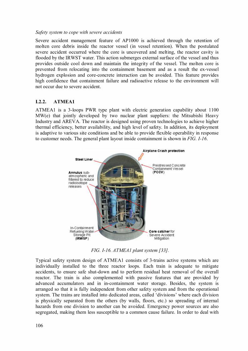
106
Safety system to cope with severe accidents
Severe accident management feature of AP1000 is achieved through the retention of
molten core debris inside the reactor vessel (in vessel retention). When the postulated
severe accident occurred where the core is uncovered and melting, the reactor cavity is
flooded by the IRWST water. This action submerges external surface of the vessel and thus
provides outside cool down and maintain the integrity of the vessel. The molten core is
prevented from relocating into the containment basement and as a result the ex-vessel
hydrogen explosion and core-concrete interaction can be avoided. This feature provides
high confidence that containment failure and radioactive release to the environment will
not occur due to severe accident.
I.2.2. ATMEA1
ATMEA1 is a 3-loops PWR type plant with electric generation capability about 1100
MW(e) that jointly developed by two nuclear plant suppliers: the Mitsubishi Heavy
Industry and AREVA. The reactor is designed using proven technologies to achieve higher
thermal efficiency, better availability, and high level of safety. In addition, its deployment
is adaptive to various site conditions and be able to provide flexible operability in response
to customer needs. The general plant layout inside containment is shown in FIG. I-16.
FIG. I-16. ATMEA1 plant system [33].
Typical safety system design of ATMEA1 consists of 3-trains active systems which are
individually installed to the three reactor loops. Each train is adequate to mitigate
accidents, to ensure safe shut-down and to perform residual heat removal of the overall
reactor. The train is also complemented with passive features that are provided by
advanced accumulators and in in-containment water storage. Besides, the system is
arranged so that it is fully independent from other safety system and from the operational
system. The trains are installed into dedicated areas, called ‘divisions’ where each division
is physically separated from the others (by walls, floors, etc.) so spreading of internal
hazards from one division to another can be avoided. Emergency power sources are also
segregated, making them less susceptible to a common cause failure. In order to deal with

107
station blackout (SBO) additional alternative AC power system (AAC) or diversity in
EPSs is provided. The safety system configuration to cope with the Design Basis Event is
shown in FIG. I-17. The system includes safety injection system, advanced accumulator,
and RHRS/CS [30]] – [32]].
FIG. I-17. General arrangement of the ATMEA1 safety system [31].
FIG. I-18. Advanced accumulator of ATMEA1 [32].
Advanced accumulator
The use of advanced accumulator in ECCS provides longer injection time to the reactor
vessel post LOCA initiation. The design allows two rates of flow going out from the
accumulator tank. At the beginning of blow down phase, the flow injection rate is high and
then at subsequent core re-flooding phase (when water level inside the accumulator tank is
lower), the flow damper switches the injection flow rate passively into low head injection.
This prolongs the injection time and at the same time integrates function of low head
injection system. Consequently the low head injection system (LHIS) is no longer needed
108
and hence provides economic benefits for the capital cost. The basic design of the advance
accumulator is shown in FIG. I-18.
Safety injection system (SIS)
The primary function of SIS is to maintain the reactor coolant inventory following a LOCA
or a main steam line break (MSLB). It consists of three identical independent trains that
each is capable to inject and recirculate medium head emergency coolant to different cold
legs of the RCS. Each train has a medium head safety injection (MHSI) pump and an
advance d accumulator pressurized by nitrogen. The suction line is connected to IRWSP
via a series of screen which protect the MHSI pumps from debris being entrained with
IRWSP fluid.
In-containment refueling water storage pit (IRWSP)
The IRWSP is a water source that located at the bottom of the containment. This placement
has the following benefits: i.e. in the event of LOCA the requirement to switch over from
injection mode to recirculation mode after the tank is empty can be avoided and in the
event of a core melt it provides water for corium cooling. In its design, the area between
IRWSP and containment wall is filled with concrete to avoid water losses during an
accident.
Containment spray system (CSS)/Residual heat removal system (RHRS)
The CSS is to provide containment spray injection in order to reduce and maintain the
reactor building pressure and temperature within acceptable level in the event where high
temperature steam is released to the containment atmosphere such as LOCA or MSLB.
The RHRS is used to perform normal shutdown cooling, maintain safe shutdown state and
refuelling conditions.
The CSS and RHRS share the same injection pump and heat exchanger. The system
consists of three independent trains with a separate suction connection to the IRWSP. Each
train is powered by independent emergency buses and backed up an emergency power
supply. They are all located in a separate division so ensure the protection against external
and internal hazards.
Extra borating system (EBS)
The EBS comprise of two identical trains. Each is equipped with a boron tank, high
pressures 100% capacity pump, test line and injection lines to the RCS. This system is to
maintain the core subcritical for safe shutdown and also can be used to deal with ATWS in
the beyond design basis event.
Emergency feed water system (EFWS)
Following a loss of normal feed water in the AOO and DBE conditions, the EFWS
provides water to the SG to ensure the removal of the heat from the RCS. The system has
three independent trains where each consists of a water storage pool, pump, control valves,
isolation valves, piping and instrumentation and is powered by a separate electrical train.
One EFWS train is placed in each division of the safeguard buildings (SB), which provides
physically separate protection in coping with external and internal hazards. The EFWS has
sufficient capacity to perform its required function even in a failure of one EFW train.

109
When a common mode failure of all EPS occurred, one of EFW pump can be powered by
an alternative AC power source.
Safety system to cope with severe accidents
The ATMEA1 design addresses severe accident through several approaches. The
approaches are mainly based on prevention of core melt and loss of containment which
would lead to a large radioactive material early release. The approaches are:
• Prevention of high pressure core melt by using reliable decay heat removal
system and primary system overpressure protection.
• Primary system discharge into containment during total loss of secondary side
cooling.
• Corium spreading using sacrificial protective material which has cooling
system to protect the basemat.
• Prevention of hydrogen detonation by using catalytic hydrogen re-combiners.
• Controlling the containment pressure by using a dedicated severe accident heat
removal system (SAHRS).
• Collection of all leaks in an annulus and prevention of bypass of the
confinement.
Countermeasure for external hazards
The ATMEA1 plant design has provisions for the impact of large commercial airplane
crash by using single reactor building with high strength concrete and thicken wall (Pre-
stressed concrete containment vessel). This feature complies with the regulation of
European countries and also with the expected regulation by US NRC in future. With this
the safety facilities are protected by segregation or bunkerization to secure the required
safety functions.

110
ANNEX II
II. Review of Engineered Safety Features and Fukushima Action Plans of Small
Modular Reactors
II.1. CAREM25
Central Argentina de Elementos Modulares (CAREM25) is a national SMR development
project based on LWR technology coordinated by the Argentine National Atomic Energy
Commission (CNEA) in collaboration with leading nuclear companies in Argentina with
the purpose to develop, design and construct advanced small nuclear power plants with
economic competitiveness and high level of safety. CAREM25 is deployed as a prototype
plant that generate 31 MW(e) to validate the innovations for future commercial version of
CAREM that will eventually generate an electric output of 150 MW(e).
CAREM25 is an integral type PWR based on indirect steam cycle with distinctive features
that simplify the design and support the objective of achieving a higher level of safety
compared with current NPP designs. Some of the design characteristics of CAREM25 are:
integrated primary coolant system, self-pressurization, core cooling by natural circulation
and in-vessel hydraulic control rod drive mechanisms. Another important characteristic are
the passive safety systems actuating during a grace period of 36 hours, where the released
energy is stored inside containment. Due to this and to the presence of additional safety
features with external coolant supply, SBO is intrinsically included into the design basis of
CAREM25, which strength the design in coping with extreme natural hazards.
The reactor vessel internals and major design characteristics of CAREM25 are shown in
FIG. II-1 and TABLE II-1.
FIG. II-1. Reactor vessel of CAREM25 (Reproduced courtesy of CNEA, Argentina)
[34].

111
TABLE II-1. DESIGN CHARACTERISTIC OF CAREM25. [34], [35]
System/ Component Design value
Core Power : 100 MW(th)
Primary System
Pressure: 12.25 MPa
Core inlet temperature: 284°C
Core outlet, riser, and dome temp. ~ saturation = 326°C
Mass flow rate: 410 kg/s
Secondary System
12 identical ‘mini helical’ steam generator ‘once-through’
type, secondary system in the tube side.
Secondary pressure: 4.7 MPa.
Superheated steam : +30°C (290°C)
Tube of similar length to equalize pressure-loss and
superheating
Fuel
PWR type FA with low enriched UO2
Enrichment: about 3.5%
Refueling cycle: 14 months
Reactor Vessel
Material: SA508 Grade 3 Class 1
Lining material: SS-304L
Height: 11 m
Inner Diameter: 3.16
Wall thickness: 0.123 m
Design internalization of Defence in Depth concept
Defence in Depth (DiD) concept was internalized in the design of CAREM25 since the
conceptual engineering. It is the base for structures, systems and components safety
classification, which allows a clear assignation of design rules and requirements to systems
important to safety.
The applied DiD concept is based on Western European Nuclear Regulators Association
(WENRA) proposal and include clarification on multiple failure events, severe accidents
and independence between levels.
The adopted approach in CAREM25 is schematically presented in FIG. II-2 and briefly
describe here:
• Level 2: The objective is the control of abnormal operation and failures associated
with anticipated operational occurrences (AOO), by means of enhanced process and
control systems (EPCS).
• Level 3: The objective is the control of events to avoid radiological releases and
prevent escalation to core melt conditions.
Design goals: to avoid fuel damage, to avoid DNB during LOCA events, to keep the core
covered and to keep the RPV and containment pressure below design limits.

112
Passive safety features of CAREM25 makes possible to have a grace period (36 hours) in
which neither operator action nor electrical power supply is required to ensure the
fulfillment of the fundamental safety functions. Based on this grace period, two different
plant states are distinguished at this level from the safety point of view:
o Plant Safe State: corresponding to the plant state reached after the actuation of
the safety system during the grace period (initial stage after initiating event).
o Final Safe State: corresponding to the plant state reached with active safety
systems, which operate after the grace period to carry the plant to conditions
equivalent to cool shutdown.
Also, in order to address the clear differences between single events and multiple failure
events without core melt, this level is divided in two sublevels according to WENRA:
• Sub-level 3a: control of Postulated Single Initiating Events (PSIE). During the
initial stage (grace period) this is done by means of the Passive Safety Systems
of the Main Line of Protection, to reach the Plant Safe State. During the final
stage, after the grace period, the control is done by means of the active Final
Safe State Systems, in order to reach Plant Final Safe State.
• Sub-level 3b: control of postulated multiple failure events (PMFE). During the
initial stage (grace period), and in case of failure of systems of the Main Line
of Protection, this is done by means of the passive Safety Systems of the
diverse line of protection, to reach the plant safe state. During the final stage,
after the grace period, the control is done by means of the active Final Safe
State Systems, in order to reach Plant Final Safe State. In case of failure of the
final safe state systems, the extension of plant safe state systems (external
supply) of this sublevel actuate for the purpose of extending the plant safe
state.
• Level 4: The objective is the control of postulated core melt accidents (PCMA) to
limit off-site releases, by means of the severe accident mitigation systems.
Design goals: to retain the corium inside RPV, to avoid hydrogen detonations and to limit
iodine releases.
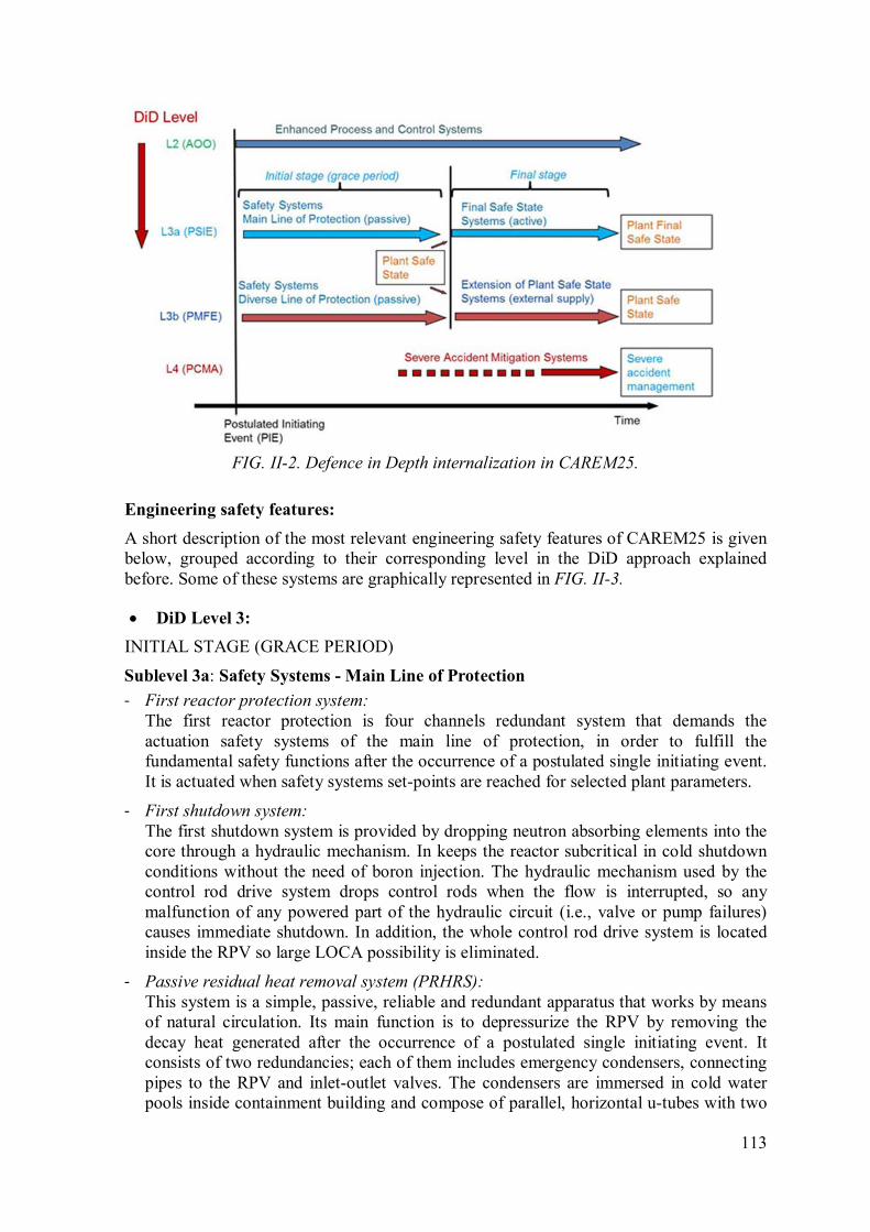
113
FIG. II-2. Defence in Depth internalization in CAREM25.
Engineering safety features:
A short description of the most relevant engineering safety features of CAREM25 is given
below, grouped according to their corresponding level in the DiD approach explained
before. Some of these systems are graphically represented in FIG. II-3.
• DiD Level 3:
INITIAL STAGE (GRACE PERIOD)
Sublevel 3a: Safety Systems - Main Line of Protection
- First reactor protection system:
The first reactor protection is four channels redundant system that demands the
actuation safety systems of the main line of protection, in order to fulfill the
fundamental safety functions after the occurrence of a postulated single initiating event.
It is actuated when safety systems set-points are reached for selected plant parameters.
- First shutdown system:
The first shutdown system is provided by dropping neutron absorbing elements into the
core through a hydraulic mechanism. In keeps the reactor subcritical in cold shutdown
conditions without the need of boron injection. The hydraulic mechanism used by the
control rod drive system drops control rods when the flow is interrupted, so any
malfunction of any powered part of the hydraulic circuit (i.e., valve or pump failures)
causes immediate shutdown. In addition, the whole control rod drive system is located
inside the RPV so large LOCA possibility is eliminated.
- Passive residual heat removal system (PRHRS):
This system is a simple, passive, reliable and redundant apparatus that works by means
of natural circulation. Its main function is to depressurize the RPV by removing the
decay heat generated after the occurrence of a postulated single initiating event. It
consists of two redundancies; each of them includes emergency condensers, connecting
pipes to the RPV and inlet-outlet valves. The condensers are immersed in cold water
pools inside containment building and compose of parallel, horizontal u-tubes with two
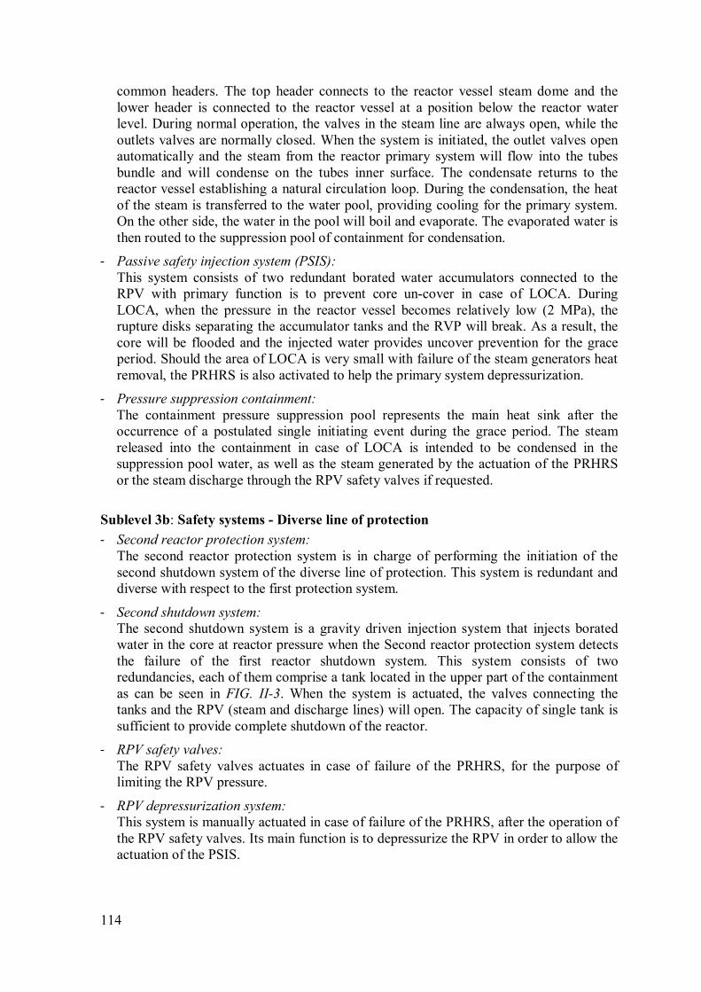
114
common headers. The top header connects to the reactor vessel steam dome and the
lower header is connected to the reactor vessel at a position below the reactor water
level. During normal operation, the valves in the steam line are always open, while the
outlets valves are normally closed. When the system is initiated, the outlet valves open
automatically and the steam from the reactor primary system will flow into the tubes
bundle and will condense on the tubes inner surface. The condensate returns to the
reactor vessel establishing a natural circulation loop. During the condensation, the heat
of the steam is transferred to the water pool, providing cooling for the primary system.
On the other side, the water in the pool will boil and evaporate. The evaporated water is
then routed to the suppression pool of containment for condensation.
- Passive safety injection system (PSIS):
This system consists of two redundant borated water accumulators connected to the
RPV with primary function is to prevent core un-cover in case of LOCA. During
LOCA, when the pressure in the reactor vessel becomes relatively low (2 MPa), the
rupture disks separating the accumulator tanks and the RVP will break. As a result, the
core will be flooded and the injected water provides uncover prevention for the grace
period. Should the area of LOCA is very small with failure of the steam generators heat
removal, the PRHRS is also activated to help the primary system depressurization.
- Pressure suppression containment:
The containment pressure suppression pool represents the main heat sink after the
occurrence of a postulated single initiating event during the grace period. The steam
released into the containment in case of LOCA is intended to be condensed in the
suppression pool water, as well as the steam generated by the actuation of the PRHRS
or the steam discharge through the RPV safety valves if requested.
Sublevel 3b: Safety systems - Diverse line of protection
- Second reactor protection system:
The second reactor protection system is in charge of performing the initiation of the
second shutdown system of the diverse line of protection. This system is redundant and
diverse with respect to the first protection system.
- Second shutdown system:
The second shutdown system is a gravity driven injection system that injects borated
water in the core at reactor pressure when the Second reactor protection system detects
the failure of the first reactor shutdown system. This system consists of two
redundancies, each of them comprise a tank located in the upper part of the containment
as can be seen in FIG. II-3. When the system is actuated, the valves connecting the
tanks and the RPV (steam and discharge lines) will open. The capacity of single tank is
sufficient to provide complete shutdown of the reactor.
- RPV safety valves:
The RPV safety valves actuates in case of failure of the PRHRS, for the purpose of
limiting the RPV pressure.
- RPV depressurization system:
This system is manually actuated in case of failure of the PRHRS, after the operation of
the RPV safety valves. Its main function is to depressurize the RPV in order to allow the
actuation of the PSIS.
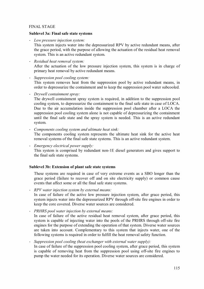
115
FINAL STAGE
Sublevel 3a: Final safe state systems
- Low pressure injection system:
This system injects water into the depressurized RPV by active redundant means, after
the grace period, with the purpose of allowing the actuation of the residual heat removal
system. This is an active redundant system.
- Residual heat removal system:
After the actuation of the low pressure injection system, this system is in charge of
primary heat removal by active redundant means.
- Suppression pool cooling system:
This system removes heat from the suppression pool by active redundant means, in
order to depressurize the containment and to keep the suppression pool water subcooled.
- Drywell containment spray:
The drywell containment spray system is required, in addition to the suppression pool
cooling system, to depressurize the containment to the final safe state in case of LOCA.
Due to the air accumulation inside the suppression pool chamber after a LOCA the
suppression pool cooling system alone is not capable of depressurizing the containment
until the final safe state and the spray system is needed. This is an active redundant
system.
- Components cooling system and ultimate heat sink:
The components cooling system represents the ultimate heat sink for the active heat
removal systems of the final safe state systems. This is an active redundant system.
- Emergency electrical power supply:
This system is comprised by redundant non-1E diesel generators and gives support to
the final safe state systems.
Sublevel 3b: Extension of plant safe state systems
These systems are required in case of very extreme events as a SBO longer than the
grace period (failure to recover off and on site electricity supply) or common cause
events that affect some or all the final safe state systems.
- RPV water injection system by external means:
In case of failure of the active low pressure injection system, after grace period, this
system injects water into the depressurized RPV through off-site fire engines in order to
keep the core covered. Diverse water sources are considered.
- PRHRS pool water injection by external means:
In case of failure of the active residual heat removal system, after grace period, this
system is capable of injecting water into the pools of the PRHRS through off-site fire
engines for the purpose of extending the operation of that system. Diverse water sources
are taken into account. Complementary to this system that injects water, one of the
following systems is required in order to fulfill the heat removal safety function.
- Suppression pool cooling (heat exchanger with external water supply):
In case of failure of the suppression pool cooling system, after grace period, this system
is capable of removing heat from the suppression pool using off-site fire engines to
pump the water needed for its operation. Diverse water sources are considered.
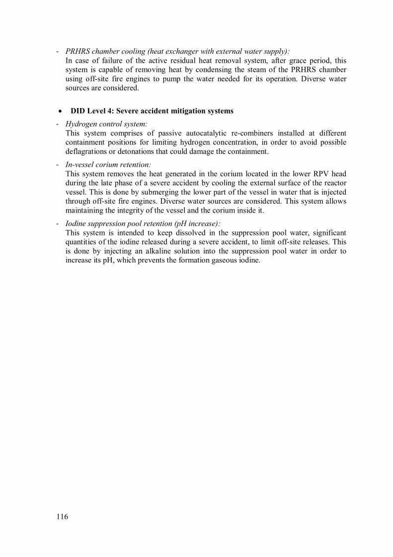
116
- PRHRS chamber cooling (heat exchanger with external water supply):
In case of failure of the active residual heat removal system, after grace period, this
system is capable of removing heat by condensing the steam of the PRHRS chamber
using off-site fire engines to pump the water needed for its operation. Diverse water
sources are considered.
• DID Level 4: Severe accident mitigation systems
- Hydrogen control system:
This system comprises of passive autocatalytic re-combiners installed at different
containment positions for limiting hydrogen concentration, in order to avoid possible
deflagrations or detonations that could damage the containment.
- In-vessel corium retention:
This system removes the heat generated in the corium located in the lower RPV head
during the late phase of a severe accident by cooling the external surface of the reactor
vessel. This is done by submerging the lower part of the vessel in water that is injected
through off-site fire engines. Diverse water sources are considered. This system allows
maintaining the integrity of the vessel and the corium inside it.
- Iodine suppression pool retention (pH increase):
This system is intended to keep dissolved in the suppression pool water, significant
quantities of the iodine released during a severe accident, to limit off-site releases. This
is done by injecting an alkaline solution into the suppression pool water in order to
increase its pH, which prevents the formation gaseous iodine.

117
(A) Reactor core
(B) Steam generators
(1) First shutdown system
(2) Second shutdown system
(3) Reinforced concrete containment
(4) Passive safety injection system
(PSIS)
(5) Pressure suppression pool
(6) Passive residual heat removal system (PRHRS)
(7) Primary depressurization system
(8) PRHRS chamber relief devices
(9) Suppression pool chamber relief valves
(10) PRHRS chamber relief ducts
(11) Drywell relief ducts
FIG. II-3. Some relevant engineering safety features of CAREM25 (Reproduced courtesy
of CNEA, Argentina).
II.2. SMART
General Description
The System-integrated Modular Advanced Reactor (SMART) is an integral type SMR with
a rated power of 330 MW(th) (100 MW(e)) for multi-purpose applications. It contains
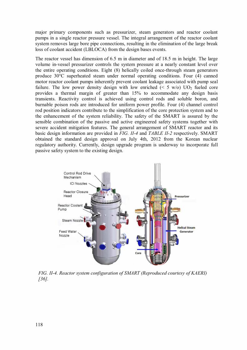
118
major primary components such as pressurizer, steam generators and reactor coolant
pumps in a single reactor pressure vessel. The integral arrangement of the reactor coolant
system removes large bore pipe connections, resulting in the elimination of the large break
loss of coolant accident (LBLOCA) from the design bases events.
The reactor vessel has dimension of 6.5 m in diameter and of 18.5 m in height. The large
volume in-vessel pressurizer controls the system pressure at a nearly constant level over
the entire operating conditions. Eight (8) helically coiled once-through steam generators
produce 30°C superheated steam under normal operating conditions. Four (4) canned
motor reactor coolant pumps inherently prevent coolant leakage associated with pump seal
failure. The low power density design with low enriched (< 5 w/o) UO2 fueled core
provides a thermal margin of greater than 15% to accommodate any design basis
transients. Reactivity control is achieved using control rods and soluble boron, and
burnable poison rods are introduced for uniform power profile. Four (4) channel control
rod position indicators contribute to the simplification of the core protection system and to
the enhancement of the system reliability. The safety of the SMART is assured by the
sensible combination of the passive and active engineered safety systems together with
severe accident mitigation features. The general arrangement of SMART reactor and its
basic design information are provided in FIG. II-4 and TABLE II-2 respectively. SMART
obtained the standard design approval on July 4th, 2012 from the Korean nuclear
regulatory authority. Currently, design upgrade program is underway to incorporate full
passive safety system to the existing design.
FIG. II-4. Reactor system configuration of SMART (Reproduced courtesy of KAERI)
[36].
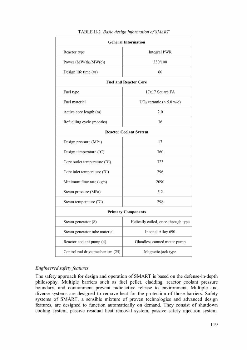
119
TABLE II-2. Basic design information of SMART
General Information
Reactor type Integral PWR
Power (MW(th)/MW(e)) 330/100
Design life time (yr) 60
Fuel and Reactor Core
Fuel type 17x17 Square FA
Fuel material UO2 ceramic (< 5.0 w/o)
Active core length (m) 2.0
Refuelling cycle (months) 36
Reactor Coolant System
Design pressure (MPa) 17
Design temperature (oC) 360
Core outlet temperature (oC) 323
Core inlet temperature (oC) 296
Minimum flow rate (kg/s) 2090
Steam pressure (MPa) 5.2
Steam temperature (oC) 298
Primary Components
Steam generator (8) Helically coiled, once-through type
Steam generator tube material Inconel Alloy 690
Reactor coolant pump (4) Glandless canned motor pump
Control rod drive mechanism (25) Magnetic-jack type
Engineered safety features
The safety approach for design and operation of SMART is based on the defense-in-depth
philosophy. Multiple barriers such as fuel pellet, cladding, reactor coolant pressure
boundary, and containment prevent radioactive release to environment. Multiple and
diverse systems are designed to remove heat for the protection of those barriers. Safety
systems of SMART, a sensible mixture of proven technologies and advanced design
features, are designed to function automatically on demand. They consist of shutdown
cooling system, passive residual heat removal system, passive safety injection system,
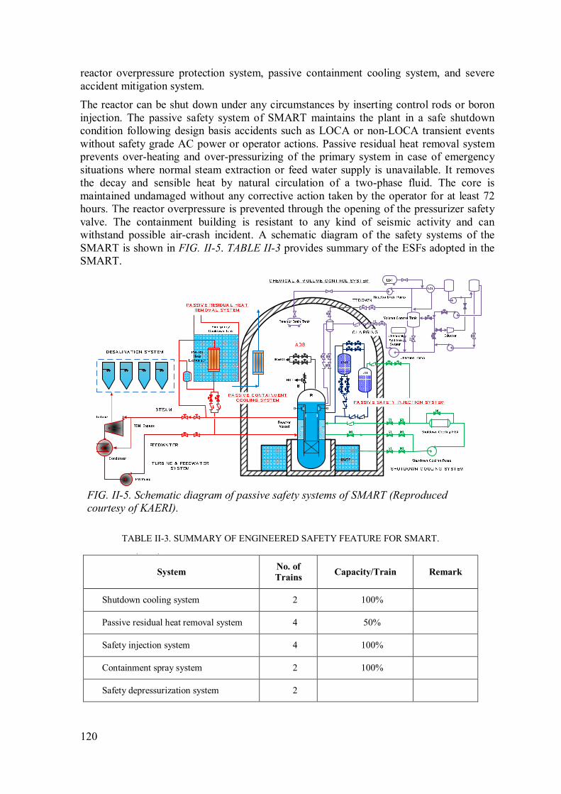
120
reactor overpressure protection system, passive containment cooling system, and severe
accident mitigation system.
The reactor can be shut down under any circumstances by inserting control rods or boron
injection. The passive safety system of SMART maintains the plant in a safe shutdown
condition following design basis accidents such as LOCA or non-LOCA transient events
without safety grade AC power or operator actions. Passive residual heat removal system
prevents over-heating and over-pressurizing of the primary system in case of emergency
situations where normal steam extraction or feed water supply is unavailable. It removes
the decay and sensible heat by natural circulation of a two-phase fluid. The core is
maintained undamaged without any corrective action taken by the operator for at least 72
hours. The reactor overpressure is prevented through the opening of the pressurizer safety
valve. The containment building is resistant to any kind of seismic activity and can
withstand possible air-crash incident. A schematic diagram of the safety systems of the
SMART is shown in FIG. II-5. TABLE II-3 provides summary of the ESFs adopted in the
SMART.
M
FIG. II-5. Schematic diagram of passive safety systems of SMART (Reproduced
courtesy of KAERI).
TABLE II-3. SUMMARY OF ENGINEERED SAFETY FEATURE FOR SMART.
TABLE 26 (cont.)
System No. of
Trains Capacity/Train Remark
Shutdown cooling system 2 100%
Passive residual heat removal system 4 50%
Safety injection system 4 100%
Containment spray system 2 100%
Safety depressurization system 2
121
TABLE 26 (cont.)
System No. of
Trains Capacity/Train Remark
Passive auto-catalytic re-combiner (12) 200%
Basic safety requirements:
• Core Damage Frequency < 10-6 / RY
• Large Radioactivity Release Frequency < 10-7 / RY
• Core Thermal Margin > 15 %
II.2.1. Shutdown cooling system (SCS)
The SCS cools down the reactor from the safe shutdown temperature to the refuelling
temperature, and maintains the RCS refuelling condition for extended period. These roles
are defined as non-safety function in the passive nuclear plants. The relief valve, which is
installed at the inlet pipe of SCS, provides a low temperature overpressure protection
(LTOP) function of the RCS. In addition, the SCS is designed to provide the safety
injection tank (SIT) refilling function which is required after 72 hours following the design
basis accidents. The SCS consists of four mechanically independent trains for the SIT
refilling function. Each train is composed of a pump, valves, pipes, and monitoring
instrumentation. Two trains share a heat exchanger.
II.2.2. Passive residual heat removal system (PRHRS)
After the reactor is shutdown, when the normal decay heat removal mechanism utilizing
the secondary system is not operable by any reason, the PRHRS brings the RCS to the safe
shutdown condition within 36 hours after accident initiation and to maintain the safe
shutdown condition for at least another 36 hours, therefore total 72 hours without any
corrective action by operator for the postulated design basis accidents. The safety
function of PRHRS is maintained continuously for a long term period when the emergency
cool down tank (ECTs) is replenished periodically.
The PRHRS consists of four independent trains with a 33.3% capacity each, and each train
is composed of an ECT, a heat exchanger and a makeup tank. In the design of PRHRS the
possibility of loss of one train by a single failure is eliminated. Each train of PRHRS has a
pair of check valves and isolation valves, both of which are installed on parallel lines.
Therefore even if one valve is failed, the whole train is still in operation. And also to
remove the possibility of common mode failure, diversity of actuator is provided. Two
kinds of different isolation valves are adopted, which are air-operated and electro-hydraulic
valves. Therefore, a single failure is no longer an issue in the design of PRHRS and three
out-of-four trains are enough to remove the residual heat after an accident occurs.
II.2.3. Passive safety injection system (PSIS)
Passive safety injection systems provide emergency core cooling for at least 72 hours
following postulated design basis accidents without operator actions or AC power.
Emergency core cooling is performed through the four (4) core make-up tanks (CMTs) and
four (4) safety injection tanks (SITs). Core cooling inventory is maintained through passive
safety injection of CMTs and SITs.

122
The four (4) CMTs with full of borated water provide makeup and boration functions to
the RCS during early stage of LOCA and non-LOCA. The top and bottom of CMT are
connected to the RCS through the pressure balance line (PBL) and the safety injection line
(SIL), respectively. Each SIL is isolated by 2 x 2 parallel closed valves, which meets
single failure criteria. Each PBL is normally open to maintain pressure of the CMT at RCS
condition. This arrangement enables the CMT to inject water to the RCS by gravity when
the isolation valves are open. The isolation valves of the CMT injection line are signaled to
open by pressurizer low pressure, containment high pressure and low steam line pressure,
etc.
The four (4) SITs are filled with borated water and nitrogen gas at atmospheric pressure.
They provide makeup water to the RCS at low pressure conditions for about 72 hours in
case of LOCA. The arrangement of the SIT is similar to that of CMT except that the
isolation valves are installed at PBL. The isolation valves of the SIT injection line are open
when the RCS pressure reaches the set point pressure.
II.2.4. Automatic depressurization system (ADS)
The ADS lowers RCS pressure so that gravity head injection from SIT becomes available
in case of LOCA. The ADS can be manually opened for total loss of feed water (TLOFW).
In addition, the ADS can provide RCS depressurizing for easy connection of shutdown
cooling system (SCS). The ADS consists of two (2) trains with two (2) stages each. One
train of ADS is operated when the water level of CMTs reaches the set point level, and
another train is operated by set point level of SITs.
II.2.5. Reactor overpressure protection system (ROPS)
The reactor overpressure protection system (ROPS) consists of two pressurizer safety
valves (PSVs) installed on the top of the reactor vessel head assembly. The purpose of the
ROPS is to reduce the reactor pressure when a postulated design basis accident related
with a control system failure occurs. Should the primary system pressure increases over the
predefined set point, the safety valves open rapidly to discharge the steam into the reactor
drain tank (RDT).
II.2.6. Passive containment cooling system (PCCS)
The safety functions of PCCS are to reduce containment pressure and temperature for main
steam line break (MSLB) or LOCA, and to remove fission products from the containment
atmosphere following LOCA. The PCCS consists of four independent trains with a 33%
capacity each, and each train is composed of a heat exchanger inside, connecting pipe and
valves. The PCCS dissipates the heat from the containment atmosphere to the environment
through the heat exchanger by natural circulation of working medium.
II.2.7. Severe accident mitigation system (SAMS)
The reactor pressure vessel is located in a cavity that can be flooded when a severe
accident occurs. The design allows the SAMS to fill the air gap under the RPV with water
from the in-containment refuelling storage tank (IRWST). This function provides an
external cooling to the vessel which then prevents the egress of the corium out of the RPV
during severe accident (in-vessel retention). Water in the IRWST floods the cavity by
gravity.

123
The combustible gas control in the containment of SMART is performed by the passive
auto-catalytic re-combiners (PARs) and containment purge system. Twelve (12) PARs
installed in the containment, designed with 200% capacity, prevent the accumulation of
hydrogen without external power supply.
Fukushima Action Plan
Ever since the Fukushima Daiichi accident, mitigation measures and facilities to cope with
severe accidents cause by extreme natural hazards have become the key safety issues to
nuclear power plants. Fukushima Daiichi accident showed that securing the continuous
cooling capability of reactor core and spent fuel pool is essential to maintain the nuclear
power plant safe.
After the Fukushima Daiichi accident, the Korean nuclear regulatory authority formed a
task team to perform a through safety audit on all the nuclear plants and facilities under
operation, construction, or development. As a result, fifty (50) improvement orders (action
items) were derived to enhance the safety level against Fukushima Daiichi type extreme
hazards including earthquake, tsunami, and flooding. Among them, ten (10) items are
applied to SMART while other items are not directly relevant to the SMART design.
TABLE II-4 shows the post-Fukushima action items applied to the standard design of
SMART.
TABLE II-4. POST-FUKUSHIMA ACTION ITEMS APPLIED TO SMART.
No. Action Item Resolution
1. Automatic Reactor Shutdown following an Earthquake > 0.18g Resolved in SSAR1)
2. Strengthen Aseismic Design for Main Control Room Panel Resolved in SSAR
3. Provide Water tight Door and Drain Pump Resolved in SSAR
4. Secure Mobile Generator and Connection Points Resolved in SSAR
5. Improve Design Requirements of Alternate AC – capacity, diverse
cooling, fuel supply Resolved in SSAR
6. Fix up Extra Transformer Anchor Bolt To be resolved in
PSAR
7. Prepare Measure to Cool-down Spent Fuel Pool Resolved in SSAR
8. Prepare Anti-Flood & Recovery for Final Heat Removal Resolved in SSAR
9. Provide Passive Hydrogen Control Device (PAR) Resolved in SSAR
10. Provide External Injection Path on Safety Injection Line Resolved in SSAR
1) Standard Safety Analysis Report
It is clear that maintaining continuous and proper core cooling capability after shutdown of
a reactor is very important. A series of realistic simulation showed that the SMART
PRHRS working on the secondary side of steam generators effectively removes decay
heat, and maintains the reactor in a stable condition for 20 days without external power and
operator action. This grace time can be extended continuously when the PRHRS
emergency cool down tanks (ECTs) are periodically replenished.
For the hydrogen control, assuming 100 % oxidation reaction of fuel zircaloy cladding
with steam after severe accident, relatively large containment volume of SMART limits the

124
average hydrogen density in the containment atmosphere below 5 volume %. Twelve (12)
PARs effectively remove the accumulation of the hydrogen, preventing possibility of
hydrogen explosion.
II.3. IRIS
IRIS is a medium sized PWR which applies an integral reactor coolant system layout in its
design. It offers a formation of single or multiple modules in one site, each having power
rating of 1000 MW(th) (about 335 MW(e)). The IRIS reactor vessel houses all nuclear
steam supply system components such as the nuclear fuel and control rods, coolant pumps,
steam generators, pressurizer, control rod drive mechanism and steel reflector. Because of
that, the size of IRIS reactor vessel is larger than the traditional loop-type PWR. Its
dimension has a diameter about 6.2 m and an overall height of 22.2 m. Some other design
parameters are presented in TABLE II-5.
Inside the reactor pressure vessel, the primary coolant moves upward through the core, the
riser region, and the place between the extended core barrel and RV inside wall where the
reactor coolant pumps is located. There are 8 pumps employed to circulate the primary
coolant. The direction of the coolant flows after the pumps is downward, going into each
corresponding helical coil steam generator module. The coolant continues down through
the annular down comer region and then back to the core. The configuration of the reactor
internal can be seen in FIG. II-6.
The IRIS design provides multiple level of defence. It also applies a very basic level of
DiD i.e., elimination of accident initiator, in addition to the traditional method using
barriers, redundancy, diversity, etc. This implementation is known as “safety by design”
approach.
To deal with any postulated accidents, the IRIS includes the following passive systems
where natural gravitational force is used in their operation instead of active components
such as pumps, fan coolers or sprays and other supporting systems [38], [39].
FIG. II-6. IRIS reactor vessel and containment [38].
125
TABLE II-5. IRIS MAJOR DESIGN PARAMETERS [39].
System/Component Design value
Core Power = 1000 MW(th)
Nuclear steam supply
system
Integral RCS
Steam temperature and pressure = 317°C , 5.8 MPa
Feed water temperature and pressure = 224°C , 6.5 MPa
Reactor coolant system Flow rate = 4700 kg/s
Operating pressure = 15.5 MPa
Core inlet/outlet temperature = 292/330°C
Fuel Enrichment = 4.95%
Cycle length = 40 – 48 months
Average burn up = 60000 MWd/tU
Reactor Vessel Inner diameter = 6.21 m
Wall thickness = 285 mm
Total height = 21.3 m
Steam generator 8 vertical, helical coil tube bundle, once through,
superheated SGs.
Thermal capacity (each) = 125 MW(th)
Reactor coolant pump 8 spool type, fully immersed pumps
Head = 19.8 m
Primary containment Pressure suppression, steel, spherical geometry 25 m
diameters.
Design pressure and temperature = 1300 kPa, 200°C
II.3.1. Passive emergency heat removal system (EHRS)
The passive EHRS consists of four independent subsystems which operate in natural
circulation for removing heat from the primary system to the refueling water storage tank
(RWST) located outside the containment. Each subsystem has a horizontal U-tube heat
exchanger immersed in the RWST and is connected to the steam generator feed and steam
lines as depicted in FIG. II-7. The steam flowing-in from the SG is condensed inside the
EHRS heat exchanger and the condensate is returned back to the SG by gravitational force.

126
FIG. II-7. Schematic diagram of the IRIS's passive safety system [38].
A single EHRS is designed to sufficiently remove decay heat load from the reactor core
when heat removal capability of the secondary system is lost. In addition to this core
cooling function, the EHRS also provides the primary system post–LOCA depressurization
function (depressurization with no loss of mass) by condensing the steam produced by the
core immediately inside the reactor vessel. This role potentially reduces the break flow
while transferring the decay heat to the environment.
II.3.2. Emergency boration tank
The emergency boration tank is intended as a diverse means to control core shutdown in
addition to the control rods. Two full-systems of emergency boration are available inside
the containment, capable to deliver borated water to the RV through the direct vessel
injection (DVI) line when the system is actuated. Besides, the tanks also serve as a limited
gravity feed makeup water to the primary system.
II.3.3. Automatic depressurization system (ADS)
The ADS consists of one leg with two parallel 4 inch lines, each with two normally closed
valves. The downstream line of the valves is directed to the pressure suppression system
pool tank and the upstream line is connected to the pressurizer steam space. The ADS
principal function is to assist the EHRS in depressurizing the reactor vessel when/if the
reactor vessel coolant inventory falls below a definite level and to ensure that the reactor
vessel and the containment pressures are equalized in timely manner so the loss of coolant
can be limited and the core uncover is prevented after the postulated LOCAs event
occurred [38].
II.3.4. Containment pressure suppression system (CPSS)
The CPSS is a system to limit the peak containment pressure after the most limiting blow
down event. This system consists of six water tanks and one common tank to store non-
condensable gas. Each water tank is associated to the containment atmosphere through a
vent pipe. The pipe going to the tank is a submerged sparger so that steam released to
containment following loss of coolant or steam/feed line break can be condensed inside the
tank. In the meantime, the non-condensable gas mixed in the steam will be collected in the

127
non-condensable storage tank. The containment pressure suppression system is capable to
limit the pressure of the containment to less than 1.0 MPa (130 psig) which is very much
lower than the containment design pressure. Besides, the water inside the suppression tank
can also be used for reactor vessel injection in the event of LOCA as this water level
provides an elevated source that can be driven by gravity to enter reactor vessel through
DVI line.
II.3.5. Long term gravity makeup system (LGMS)
The design of IRIS containment comes with a cavity in lower containment (RV cavity) that
is specifically planned to be able to collect liquid and any condensate from the containment
in the event of LOCA. Following a LOCA, the water floods the cavity and at a definite
elevation forms a gravity head which sufficient to provide coolant make up to the reactor
vessel through DVI line. The water in cavity also ensures that the RV surface is wetted and
cooled so the integrity of the vessel is maintained in the event of postulated core damage
and the corium can be retained inside the vessel. In additions, LGMS also provides a path
for gravity injection to the coolant system from the CPSS.
II.4. mPower
The mPower is an advanced integrated PWR reactor which has a rated power output of
approximately 530 MW(th) and can be operated up to 4 years between refueling. The size
of reactor vessel is approximately 83 feet long by 13 feet in diameter.
Launched by the Generation mPower LLC, the reactor design incorporates several inherent
safety features and employs proven and standard technology with simpler and smaller
components. Its primary system and secondary loop flows are shown in FIG. II-8. All the
mPower’s nuclear steam supply system components such as steam generator, pressurizer,
core and CRDM are arranged inside the reactor vessel and the circulation of the primary
coolant is powered by canned motor pumps attached at the upper part of the vessel around
the pressurizer. As a result, the reactor coolant does not leave the vessel and the possibility
of large LOCA in primary system like in conventional reactors is eliminated. Only small
penetrations for a water level instrumentation tap, pressurizer sprays line, and for letdown,
purification and make up that are connected to the vessel. These penetrations are placed
well above the top of the core so it ensures that the reactor will remain be covered by water
during a LOCA accident. The design of the reactor also includes large water inventory in
the vessel which also guarantees that during the blow down phase in response to the LOCA
there is still enough water to cover the core.
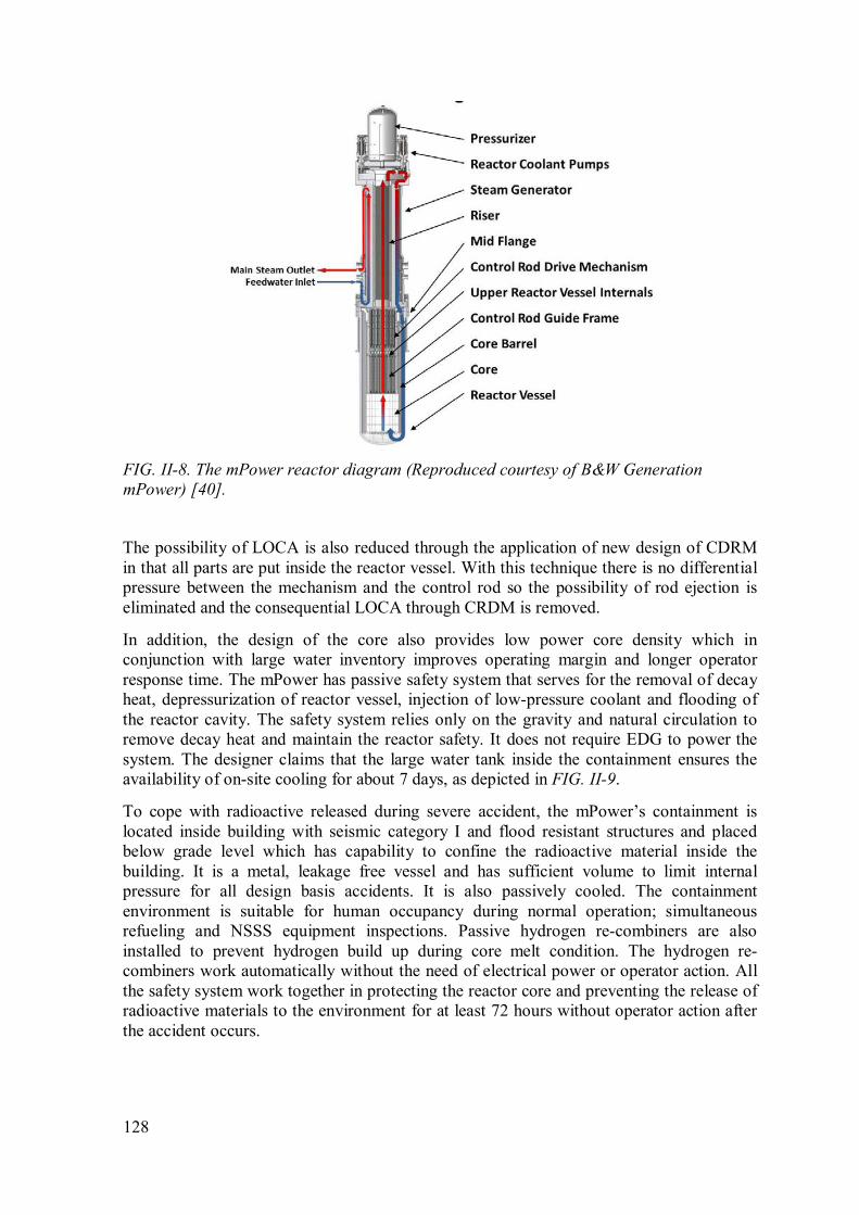
128
FIG. II-8. The mPower reactor diagram (Reproduced courtesy of B&W Generation
mPower) [40].
The possibility of LOCA is also reduced through the application of new design of CDRM
in that all parts are put inside the reactor vessel. With this technique there is no differential
pressure between the mechanism and the control rod so the possibility of rod ejection is
eliminated and the consequential LOCA through CRDM is removed.
In addition, the design of the core also provides low power core density which in
conjunction with large water inventory improves operating margin and longer operator
response time. The mPower has passive safety system that serves for the removal of decay
heat, depressurization of reactor vessel, injection of low-pressure coolant and flooding of
the reactor cavity. The safety system relies only on the gravity and natural circulation to
remove decay heat and maintain the reactor safety. It does not require EDG to power the
system. The designer claims that the large water tank inside the containment ensures the
availability of on-site cooling for about 7 days, as depicted in FIG. II-9.
To cope with radioactive released during severe accident, the mPower’s containment is
located inside building with seismic category I and flood resistant structures and placed
below grade level which has capability to confine the radioactive material inside the
building. It is a metal, leakage free vessel and has sufficient volume to limit internal
pressure for all design basis accidents. It is also passively cooled. The containment
environment is suitable for human occupancy during normal operation; simultaneous
refueling and NSSS equipment inspections. Passive hydrogen re-combiners are also
installed to prevent hydrogen build up during core melt condition. The hydrogen re-
combiners work automatically without the need of electrical power or operator action. All
the safety system work together in protecting the reactor core and preventing the release of
radioactive materials to the environment for at least 72 hours without operator action after
the accident occurs.

129
FIG. II-9. Decay heat removal strategy of the mPower [40].
II.5. NuScale
A single NuScale Power Module (NPM) is designed to produce 50 MW(e) (gross) and 160
MW(th) (gross). The 12-NPM power plant is expected to produce electric output as 570
MW(e) (net, nominal). NuScale, an integrated PWR system, is designed by taking benefits
of existing knowledge and application of practical design tools of light water cooled PWR
technology. The module of NuScale is entirely assembled in factory and can be delivered
to the intended site by rail, truck or barge so increases its economics and deployment
flexibility. The size of reactor vessel is approximately 19.2 m long by 2.8 m in diameter
and is enclosed in a steel containment that is 25 m long by 4.6 m in diameter. A complete
single module system and some basic plant parameters can be seen in FIG. II-10 and
TABLE II-6.
The RPV for NuScale contains all the nuclear steam supply system (NSSS), i.e. reactor
core, helical coil steam generator and pressurizer. The steam generator is made up of two
independent sets of tube bundles with separate feed-water inlet and steam outlet lines. A
superheated steam is generated inside the tubes that boil the feed water injected by pump.
The pressure inside the reactor vessel is controlled by a set of pressurizer heaters
positioned in the upper head of the vessel.
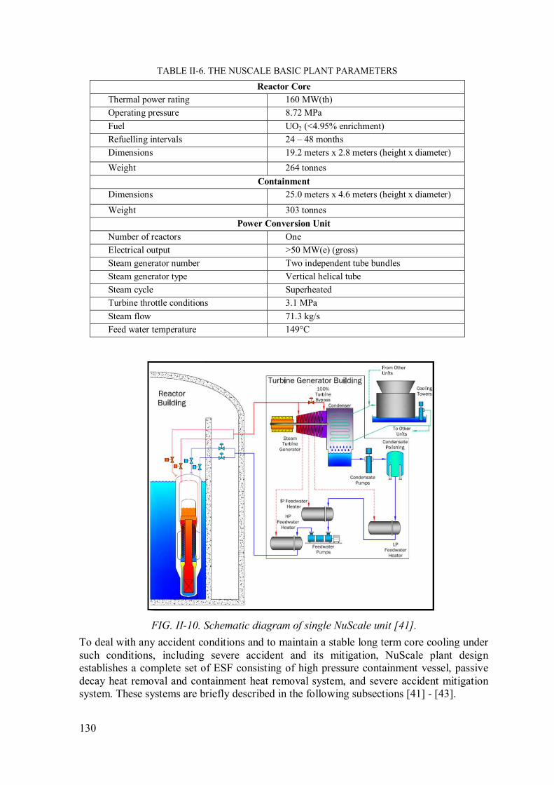
130
TABLE II-6. THE NUSCALE BASIC PLANT PARAMETERS
Reactor Core
Thermal power rating 160 MW(th)
Operating pressure 8.72 MPa
Fuel UO2 (<4.95% enrichment)
Refuelling intervals 24 – 48 months
Dimensions 19.2 meters x 2.8 meters (height x diameter)
Weight 264 tonnes
Containment
Dimensions 25.0 meters x 4.6 meters (height x diameter)
Weight 303 tonnes
Power Conversion Unit
Number of reactors One
Electrical output >50 MW(e) (gross)
Steam generator number Two independent tube bundles
Steam generator type Vertical helical tube
Steam cycle Superheated
Turbine throttle conditions 3.1 MPa
Steam flow 71.3 kg/s
Feed water temperature 149°C
FIG. II-10. Schematic diagram of single NuScale unit [41].
To deal with any accident conditions and to maintain a stable long term core cooling under
such conditions, including severe accident and its mitigation, NuScale plant design
establishes a complete set of ESF consisting of high pressure containment vessel, passive
decay heat removal and containment heat removal system, and severe accident mitigation
system. These systems are briefly described in the following subsections [41] - [43].

131
II.5.1. High pressure containment
The containment of NuScale plant is dedicated for three key safety functions i.e., to
contain radioactivity release in case of the occurrences of postulated accident, to guard the
reactor pressure vessel and its internals from external exposures, and to be an interfacing
medium for decay heat removal following an accident or normal reactor shutdown. These
features distinguish NuScale’s containment from current containment designs, as shown in
FIG. II-11.
The containment vessel of NuScale is made of a steel cylinder having an outside diameter
of about 15 ft and an overall height about 65 ft. This containment casings reactor pressure
vessel, control rod drive mechanisms and other related components and it is placed under
water in the reactor pool which provides stable cooling for the containment vessel. Under
LOCA conditions this placement allows a passive heat sink for the heat removal. The
containment vessel is designed to withstand the high temperature and pressure (5.5 MPa or
800 psia) of any design basis accident as well as the environment of the reactor pool [41].
The equilibrium pressure between reactor and containment following any LOCA is always
below containment design pressure.
FIG. II-11. Containment vessel of NuScale [41].
Under normal operating conditions, the containment is maintained at deep vacuum so that
it provides barrier against heat loss from the reactor vessel. With this method, the reactor
vessel does not require surface insulation and the potential of sump screen blockage is
eliminated. Moreover, the deep vacuum increases steam condensation rates when safety
valve exhausts steam into this space. By maintaining the vacuum condition, the corrosion
and humidity problem is also reduced and the creation of a combustible hydrogen mixture
in the event of severe accident is prevented. Furthermore, due to its relatively small size,
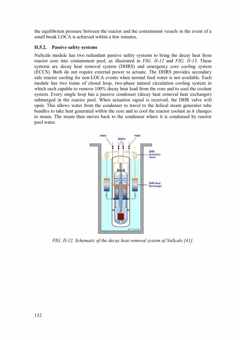
132
the equilibrium pressure between the reactor and the containment vessels in the event of a
small break LOCA is achieved within a few minutes.
II.5.2. Passive safety systems
NuScale module has two redundant passive safety systems to bring the decay heat from
reactor core into containment pool, as illustrated in FIG. II-12 and FIG. II-13. These
systems are decay heat removal system (DHRS) and emergency core cooling system
(ECCS). Both do not require external power to actuate. The DHRS provides secondary
side reactor cooling for non-LOCA events when normal feed water is not available. Each
module has two trains of closed loop, two-phase natural circulation cooling system in
which each capable to remove 100% decay heat load from the core and to cool the coolant
system. Every single loop has a passive condenser (decay heat removal heat exchanger)
submerged in the reactor pool. When actuation signal is received, the DHR valve will
open. This allows water from the condenser to travel to the helical steam generator tube
bundles to take heat generated within the core and to cool the reactor coolant as it changes
to steam. The steam then moves back to the condenser where it is condensed by reactor
pool water.
FIG. II-12. Schematic of the decay heat removal system of NuScale [41].
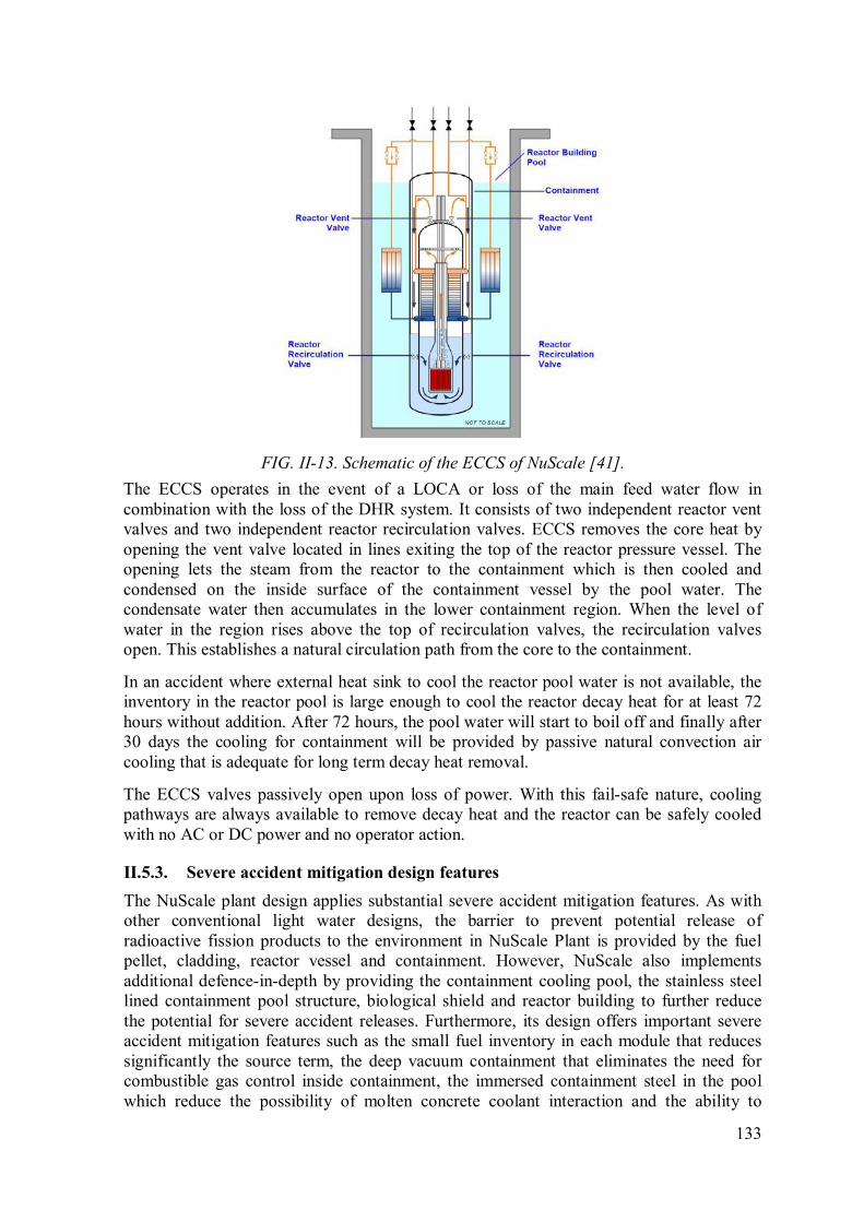
133
FIG. II-13. Schematic of the ECCS of NuScale [41].
The ECCS operates in the event of a LOCA or loss of the main feed water flow in
combination with the loss of the DHR system. It consists of two independent reactor vent
valves and two independent reactor recirculation valves. ECCS removes the core heat by
opening the vent valve located in lines exiting the top of the reactor pressure vessel. The
opening lets the steam from the reactor to the containment which is then cooled and
condensed on the inside surface of the containment vessel by the pool water. The
condensate water then accumulates in the lower containment region. When the level of
water in the region rises above the top of recirculation valves, the recirculation valves
open. This establishes a natural circulation path from the core to the containment.
In an accident where external heat sink to cool the reactor pool water is not available, the
inventory in the reactor pool is large enough to cool the reactor decay heat for at least 72
hours without addition. After 72 hours, the pool water will start to boil off and finally after
30 days the cooling for containment will be provided by passive natural convection air
cooling that is adequate for long term decay heat removal.
The ECCS valves passively open upon loss of power. With this fail-safe nature, cooling
pathways are always available to remove decay heat and the reactor can be safely cooled
with no AC or DC power and no operator action.
II.5.3. Severe accident mitigation design features
The NuScale plant design applies substantial severe accident mitigation features. As with
other conventional light water designs, the barrier to prevent potential release of
radioactive fission products to the environment in NuScale Plant is provided by the fuel
pellet, cladding, reactor vessel and containment. However, NuScale also implements
additional defence-in-depth by providing the containment cooling pool, the stainless steel
lined containment pool structure, biological shield and reactor building to further reduce
the potential for severe accident releases. Furthermore, its design offers important severe
accident mitigation features such as the small fuel inventory in each module that reduces
significantly the source term, the deep vacuum containment that eliminates the need for
combustible gas control inside containment, the immersed containment steel in the pool
which reduce the possibility of molten concrete coolant interaction and the ability to

134
equilibrate the pressure of reactor and containment which decrease the potential of a high
pressure “corium” melt ejection. With all these combinations the NuScale plant design
offers substantial advantages for emergency planning and response.
II.6. Westinghouse SMR
The Westinghouse SMR is an integral PWR that capable to supply a thermal output of 800
MW(t) and an electric output of about 225 MW(e) as a stand-alone unit. The core is made
up of 89 item of 17x17 robust fuel assemblies (RFA) with active length of 8 ft. Eight axial-
flow seal-less pumps mounted to the shell of the reactor vessel just below the closure
flange provide the reactor coolant flow through the fuel assemblies necessary to operate
the plant, as shown in FIG. II-14. The upper internals of the reactor support 37 control rod
drive mechanisms (CRDMs) used to control reactivity. The reactor module employs an
advanced evolution of a straight tube steam generator with a steam separating drum located
outside of the containment vessel. The entire plant is designed for fully modular
construction with all components shippable by rail, truck, or barge. Construction period
predicted can be completed within an 18-24 month project schedule [44].
The plant is equipped with passive safety features derived from the AP1000 plant design.
Configuration of the passive cooling system is shown in FIG. II-14. The main components
of the passive core cooling systems are a high pressure steel containment vessel, four core
makeup tanks (CMTs), an in-containment pool (ICP) and associated ICP tanks, an
automatic depressurization system (ADS), an outside containment pool (OCP) and two
ultimate heat sink (UHS) tanks. Connected to the CMTs are passive residual heat removal
heat exchangers. Altogether, these components serve as the protection required to mitigate
the various initiating faults. The safety systems is designed to safely shut down the nuclear
reaction, remove decay heat following shutdown, guarantee that the reactor core remains
covered with water to maintain effective cooling, and provide long term cooling and
shutdown.
FIG. II-14. The Westinghouse SMR [45].

135
II.6.1. Reactivity control system
Westinghouse SMR relies on gravity driven control rods and borated water injection to
control the reactor core’s reactivity. The control rods will be rapidly inserted and shutdown
the reactor when the protection system sends a signal to de-energize latches holding the rod
out of the core. In an unlikely event that the control rods do not fall into the core or event
occurs while at a shutdown condition, highly borated water is injected from CMTs. This
alternate reactivity control method is performed passively through gravity-driven liquid
flow. This CMT water supply is also intended for long term reactivity control of the plant.
II.6.2. Decay heat removal
The Westinghouse SMR has a unique approach to remove the core’s decay heat. It uses the
steam generator and large water volume in the steam drum to provide immediate residual
heat removal during most of accident scenarios. The steam drum provides a gravity driven
water supply to the steam generator tube and should water is heated up and became steam
in the SG tubes, the steam will be going back to the steam drum again. Inside the steam
drum droplet is separated and collected and sent again to the SG tube. This provides a
natural circulation cooling through SG and steam drum. If power supply is available, pump
is available to maintain the inventory of the steam drum and provide water supply to the
steam generator tube.
For an extended station blackout condition, the plant utilizes heat exchanger to perform
safety grade passive decay heat removal. The heat exchanger is integrated into each of the
four CMTs. The configuration on how the heat exchanger is combined with the CMT and
how the CMT is connected to the vessel can be seen in FIG. II-15. As shown, the bottom
of CMT is connected via valves to DVI line and the upper side of CMT in connected with
balanced line to the upper side of the pressure vessel. During SBO, the water inside steam
drum would be empty after sometime and this will trigger the opening of the CMT valves.
Upon opening of the valves, the cold water falls into the RCS beginning a natural
circulation cooling loop. In the meantime, the heat exchanger within the CMTs allows for
heat transfer to a secondary loop of cooling water.
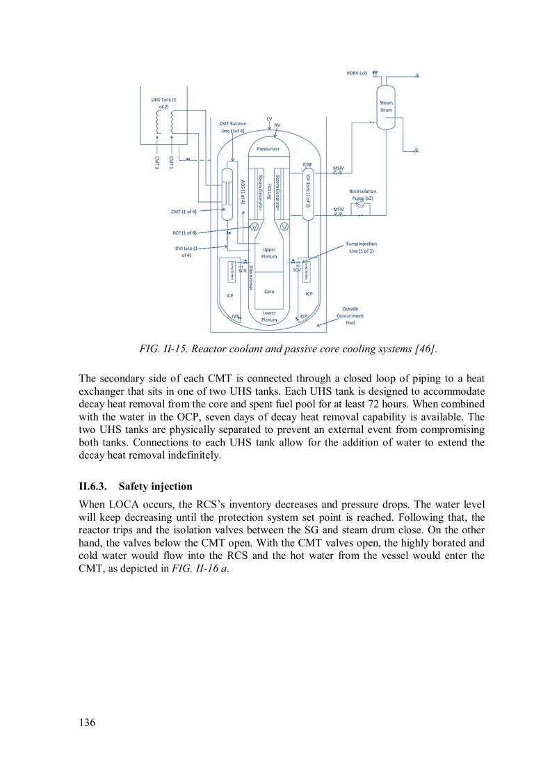
136
FIG. II-15. Reactor coolant and passive core cooling systems [46].
The secondary side of each CMT is connected through a closed loop of piping to a heat
exchanger that sits in one of two UHS tanks. Each UHS tank is designed to accommodate
decay heat removal from the core and spent fuel pool for at least 72 hours. When combined
with the water in the OCP, seven days of decay heat removal capability is available. The
two UHS tanks are physically separated to prevent an external event from compromising
both tanks. Connections to each UHS tank allow for the addition of water to extend the
decay heat removal indefinitely.
II.6.3. Safety injection
When LOCA occurs, the RCS’s inventory decreases and pressure drops. The water level
will keep decreasing until the protection system set point is reached. Following that, the
reactor trips and the isolation valves between the SG and steam drum close. On the other
hand, the valves below the CMT open. With the CMT valves open, the highly borated and
cold water would flow into the RCS and the hot water from the vessel would enter the
CMT, as depicted in FIG. II-16 a.

137
a. LOCA blow down b. CMT Natural Circulation / Draining
FIG. II-16. Loss of coolant accident in Westinghouse SMR [46], [47].
Some of the inventory going out from the vessel during LOCA will condense in the
containment and collect at the bottom. As the containment pressure increase, the disk in
the ICP will rupture to equalize the ICP and containment pressures. As more water
inventory released from the RPV and more heat transferred through the CMT, the water in
the OCP and UHS tank begins to boil. At the time the RCS level reaches the elevation of
the CMT balance lines, steam enter the lines and breaks the natural circulation of liquid
water. This makes the CMT drains cooling water to the RPV as can be seen in FIG. II-16
b. At the same time, the protection system signal is generated to open the ADS valves
attached at the line of CMT, the valves at the top of the ICP tanks and the valves into the
RPV. This opening allows the RCS to equalize with the containment. As the pressure goes
to equilibrium, the head in the ICP tanks is high enough to inject water through check
valves into RPV, as shown in FIG. II-17 a.
a. ADS actuation / ICP tank injection b. Long term core cooling
FIG. II-17. Safety injection and long term cooling [46], [47].
138
II.6.4. Long term cooling
As a result of draining the ICP tank and CMT, the water level in containment sump is high
enough to be able to deliver water flow into the vessel. Inside the vessel, the water heats up
and evaporate due to decay heat in the core. Some steam exits the vessel through ADS
valves and some other condenses in CMT heat exchanger which then the condensate goes
back to the vessel again. This process continues indefinitely as long as condensation on the
containment wall still happens. During this period, the OCP water is boiling. The water
evaporates and its level gradually drops until the level where the valves connecting the
OCP with UHS tanks automatically open, as depicted in FIG. II-17 b. The UHS tank then
refills the OCP. The capacity of each UHS tank is able to remove decay heat for about 72
hours. Connections to each UHS tank allow for the addition of water to maintain water in
the pool indefinitely.

139
CONTRIBUTORS TO DRAFTING AND REVIEW
Alamgir, Md. GE Hitachi Nuclear Energy, United States of America
Aritomi, M. Tokyo Institute of Technology, Japan
Banoori, S. M. International Atomic Energy Agency
Atique, M. World Association of Nuclear Operators (WANO)
Bylov, I. OKBM Afrikantov, Russian Federation
Choi, S. Korea Atomic Energy Research Institute (KAERI), Republic of Korea
Garcia, M. CNEA, Argentina
Gimenez, M. CNEA, Argentina
Grinberg, M. CNEA, Argentina
Hidayatullah, H. International Atomic Energy Agency
Ingersoll, D.T. NuScale Incorporation, USA
Jilani, G. International Atomic Energy Agency
Kanagawa, T. ATMEA Company, France
Kim, M. International Atomic Energy Agency
Koshy, T. International Atomic Energy Agency
Kuznetsov, V. International Atomic Energy Agency
Marquino, W. GE Hitachi Nuclear Energy, United States of America
Nayak, A.K. Bhabha Atomic Research Centre (BARC), India
Park, K.B. Korea Atomic Energy Research Institute (KAERI), Republic of Korea
Qureshi, K.R. Pakistan Atomic Energy Commission (PAEC), Pakistan
Ricotti, M.E. Politecnico di Milano, Italy
Song, D. China National Nuclear Corporation (CNNC), China

140
Subki, M.H. International Atomic Energy Agency
Susyadi, S. International Atomic Energy Agency
Syarip, S. National Nuclear Energy Agency (BATAN), Indonesia
Temple, R. Generation mPower, USA
Ui, A. Central Research Institute of Electric Power Industry (CRIEPI), Japan
Veshnyakov, K. OKBM Afrikantov, Russian Federation
Yamada, K. International Atomic Energy Agency
Zeliang, C. Indian Institute of Technology Kanpur, India
Consultants Meetings
Vienna, Austria: 30 May – 1 June 2012,
11 – 13 September 2012 and 2 – 5 March 2015
Technical Meetings
Chengdu, China: 2 – 5 September 2013,
Vienna, Austria: 2 – 5 June 2014
@ No. 23
ORDERING LOCALLYIn the following countries, IAEA priced publications may be purchased from the sources listed below or from major local booksellers.
Orders for unpriced publications should be made directly to the IAEA. The contact details are given at the end of this list.
AUSTRALIADA Information Services648 Whitehorse Road, Mitcham, VIC 3132, AUSTRALIA Telephone: +61 3 9210 7777 Fax: +61 3 9210 7788 Email: [email protected] Web site: http://www.dadirect.com.au
BELGIUMJean de LannoyAvenue du Roi 202, 1190 Brussels, BELGIUM Telephone: +32 2 5384 308 Fax: +32 2 5380 841 Email: [email protected] Web site: http://www.jean-de-lannoy.be
CANADARenouf Publishing Co. Ltd.5369 Canotek Road, Ottawa, ON K1J 9J3, CANADA Telephone: +1 613 745 2665 Fax: +1 643 745 7660 Email: [email protected] Web site: http://www.renoufbooks.com
Bernan Associates4501 Forbes Blvd., Suite 200, Lanham, MD 20706-4391, USA Telephone: +1 800 865 3457 Fax: +1 800 865 3450 Email: [email protected] Web site: http://www.bernan.com
CZECH REPUBLICSuweco CZ, spol. S.r.o.Klecakova 347, 180 21 Prague 9, CZECH REPUBLIC Telephone: +420 242 459 202 Fax: +420 242 459 203 Email: [email protected] Web site: http://www.suweco.cz
FINLANDAkateeminen KirjakauppaPO Box 128 (Keskuskatu 1), 00101 Helsinki, FINLAND Telephone: +358 9 121 41 Fax: +358 9 121 4450 Email: [email protected] Web site: http://www.akateeminen.com
FRANCEForm-Edit5 rue Janssen, PO Box 25, 75921 Paris CEDEX, FRANCE Telephone: +33 1 42 01 49 49 Fax: +33 1 42 01 90 90 Email: [email protected] Web site: http://www.formedit.fr
Lavoisier SAS14 rue de Provigny, 94236 Cachan CEDEX, FRANCE Telephone: +33 1 47 40 67 00 Fax: +33 1 47 40 67 02 Email: [email protected] Web site: http://www.lavoisier.fr
L’Appel du livre99 rue de Charonne, 75011 Paris, FRANCE Telephone: +33 1 43 07 50 80 Fax: +33 1 43 07 50 80 Email: [email protected] Web site: http://www.appeldulivre.fr
GERMANYGoethe Buchhandlung Teubig GmbHSchweitzer Fachinformationen Willstätterstrasse 15, 40549 Düsseldorf, GERMANY Telephone: +49 (0) 211 49 8740 Fax: +49 (0) 211 49 87428 Email: [email protected] Web site: http://www.goethebuch.de
HUNGARYLibrotade Ltd., Book ImportPF 126, 1656 Budapest, HUNGARY Telephone: +36 1 257 7777 Fax: +36 1 257 7472 Email: [email protected] Web site: http://www.librotade.hu
INDIAAllied Publishers1st Floor, Dubash House, 15, J.N. Heredi Marg, Ballard Estate, Mumbai 400001, INDIA Telephone: +91 22 2261 7926/27 Fax: +91 22 2261 7928 Email: [email protected] Web site: http://www.alliedpublishers.com
Bookwell3/79 Nirankari, Delhi 110009, INDIA Telephone: +91 11 2760 1283/4536 Email: [email protected] Web site: http://www.bookwellindia.com
ITALYLibreria Scientifica “AEIOU”Via Vincenzo Maria Coronelli 6, 20146 Milan, ITALY Telephone: +39 02 48 95 45 52 Fax: +39 02 48 95 45 48 Email: [email protected] Web site: http://www.libreriaaeiou.eu
JAPANMaruzen Co., Ltd.1-9-18 Kaigan, Minato-ku, Tokyo 105-0022, JAPANTelephone: +81 3 6367 6047 Fax: +81 3 6367 6160Email: [email protected] Web site: http://maruzen.co.jp
NETHERLANDSMartinus Nijhoff InternationalKoraalrood 50, Postbus 1853, 2700 CZ Zoetermeer, NETHERLANDS Telephone: +31 793 684 400 Fax: +31 793 615 698 Email: [email protected] Web site: http://www.nijhoff.nl
Swets Information Services Ltd.PO Box 26, 2300 AA LeidenDellaertweg 9b, 2316 WZ Leiden, NETHERLANDS Telephone: +31 88 4679 387 Fax: +31 88 4679 388 Email: [email protected] Web site: http://www.swets.com
SLOVENIACankarjeva Zalozba ddKopitarjeva 2, 1515 Ljubljana, SLOVENIA Telephone: +386 1 432 31 44 Fax: +386 1 230 14 35 Email: [email protected] Web site: http://www.mladinska.com/cankarjeva_zalozba
SPAINDiaz de Santos, S.A.Librerias Bookshop Departamento de pedidos Calle Albasanz 2, esquina Hermanos Garcia Noblejas 21, 28037 Madrid, SPAIN Telephone: +34 917 43 48 90 Fax: +34 917 43 4023 Email: [email protected] Web site: http://www.diazdesantos.es
UNITED KINGDOMThe Stationery Office Ltd. (TSO)PO Box 29, Norwich, Norfolk, NR3 1PD, UNITED KINGDOM Telephone: +44 870 600 5552 Email (orders): [email protected] (enquiries): [email protected] Web site: http://www.tso.co.uk
UNITED STATES OF AMERICABernan Associates4501 Forbes Blvd., Suite 200, Lanham, MD 20706-4391, USA Telephone: +1 800 865 3457 Fax: +1 800 865 3450 Email: [email protected] Web site: http://www.bernan.com
Renouf Publishing Co. Ltd.812 Proctor Avenue, Ogdensburg, NY 13669, USA Telephone: +1 888 551 7470 Fax: +1 888 551 7471 Email: [email protected] Web site: http://www.renoufbooks.com
United Nations300 East 42nd Street, IN-919J, New York, NY 1001, USA Telephone: +1 212 963 8302 Fax: 1 212 963 3489 Email: [email protected] Web site: http://www.unp.un.org
Orders for both priced and unpriced publications may be addressed directly to:IAEA Publishing Section, Marketing and Sales Unit, International Atomic Energy Agency Vienna International Centre, PO Box 100, 1400 Vienna, Austria Telephone: +43 1 2600 22529 or 22488 • Fax: +43 1 2600 29302 Email: [email protected] • Web site: http://www.iaea.org/books


16-05781

International Atomic Energy AgencyVienna
ISBN 978–92–0–100716–2ISSN 1011–4289
Design Safety Considerations for Water Cooled Sm
all Modular Reactors Incorporating Lessons Learned from
the Fukushima Daiichi Accident
IAEA-TECDOC-1785


![Iaea Tecdoc 1162[1]](https://static.fdocuments.net/doc/165x107/577ce3d51a28abf1038d245d/iaea-tecdoc-11621.jpg)