
I3105 · PDF fileI3105 . WORKSHEET . Planned Route ... Destination: Mobile Regional via Radar...
33
I3105 WORKSHEET Planned Route: Takeoff: KNSE, RWY 5 Altitude: 6,000’ Airspeed 200 KIAS Destination: Mobile Regional via Radar Departure PENSI V-198 BFM SQWID Approaches: KMOB VOR or TACAN-A Alternate: KPNS via SAINT V-198 PENSI 3,000’ Syllabus Notes Shall be conducted under simulated night conditions Conducted in the OFT Expected to fly all maneuvers without the use of FMS navigation o Left MFD will be set to Frequency page Special Syllabus Requirements None Discuss a. ARCING and Arcing approach FTI Procedures Navigation to the IAF o Feeder Fix o Airway o PTP Estimating 5 nm from IAF o GPS b. Night procedures There are no specific night procedures for instrument flights. The Contact FTI chapter 11 “NIGHT CONTACT” covers topics that are common to all night flights. c. Night lighting Airport sketch o Runway Edge Lighting HIRL MIRL LIRL o REIL o Threshold Lighting Approach end Departure end 1
Transcript of I3105 · PDF fileI3105 . WORKSHEET . Planned Route ... Destination: Mobile Regional via Radar...

I3105 WORKSHEET
Planned Route:
Takeoff: KNSE, RWY 5 Altitude: 6,000’ Airspeed 200 KIAS Destination: Mobile Regional via Radar Departure PENSI V-198 BFM SQWID Approaches: KMOB VOR or TACAN-A Alternate: KPNS via SAINT V-198 PENSI 3,000’
Syllabus Notes Shall be conducted under simulated night conditions Conducted in the OFT Expected to fly all maneuvers without the use of FMS navigation
o Left MFD will be set to Frequency page Special Syllabus Requirements None Discuss
a. ARCING and Arcing approach FTI Procedures Navigation to the IAF
o Feeder Fix o Airway o PTP
Estimating 5 nm from IAF o GPS
b. Night procedures There are no specific night procedures for instrument flights. The Contact FTI
chapter 11 “NIGHT CONTACT” covers topics that are common to all night flights. c. Night lighting Airport sketch
o Runway Edge Lighting HIRL MIRL LIRL
o REIL o Threshold Lighting
Approach end Departure end
1
FTC
Highlight
FTC
Highlight
FTC
Highlight
FTC
Highlight
FTC
Highlight
FTC
Highlight
FTC
Highlight
FTC
Highlight
FTC
Highlight
FTC
Highlight
FTC
Highlight
FTC
Highlight
FTC
Highlight
CUBIC
Highlight
CUBIC
Highlight

2
o Approach Lighting ALSF-1, ALSF-2 SALS/SASLF, SSALR, MALS/MALSF or SSALS/SSALSF MALSR
o VASI/PAPI Pilot controlled Lighting Airport beacons
o Civilian o Military
d. Night cockpit setup
e. Circling Maneuvers
f. Hydraulic system malfunctions
FTC
Highlight
FTC
Highlight
CUBIC
Highlight
CUBIC
Highlight
CUBIC
Highlight
CUBIC
Highlight
CUBIC
Highlight
CUBIC
Highlight
CUBIC
Highlight
CUBIC
Highlight
CUBIC
Highlight

T-6B Radio Instruments I3100 Block STUDENT GRADE SHEET DATE __________________ INSTRUCTOR __________________________ MEDIA: OFT VT- ________ BRIEF TIME: ________ NAME: ________________________________ EVENT:__________
# MANEUVER MIF I3101 I3102 I3103 I3104 I3105 13106 1 GENERAL KNOWLEDGE / PROCEDURES 3+ X X X X X X 2 EMERGENCY PROCEDURES 3+ X X X X X X 3 HEADWORK / SITUATIONAL AWARENESS 3+ X X X X X X 4 BASIC AIRWORK 3+ X X X X X X 5 IN-FLIGHT CHECKS / FUEL MANAGEMENT 3+ X X X X X X 6 IN-FLIGHT PLANNING/AREA ORIENTATION 3 7 TASK MANAGEMENT 3+ X X X X X X 8 COMMUNICATION 3+ X X X X X X 9 MISSION PLANNING/BRIEFING/DEBRIEFING 3+ X X X X X X 10 GROUND OPERATIONS 4 11 TAKEOFF 4+ X X X X X X 12 DEPARTURE 3+ X X X X X X 44 RADIAL INTERCEPTS 3+ X X X 45 POINT-TO-POINT 3+ X 49 HOLDING 2+ X X X X 50 ENROUTE PROCEDURES 2+ X X X X X X 51 ENROUTE DESCENT 2+ X X X X X X 52 HIGH-ALTITUDE APPROACH 2 53 TEARDROP APPROACH 2+ X 54 ARCING APPROACH 2+ X 55 HILO APPROACH 2+ X 56 PROCEDURE TURN APPROACH 2+ X 57 RVFAC APPROACH 2+ X 58 GPS APPROACH 2 59 PAR APPROACH 2+ X 60 ASR APPROACH 2+ X 61 VOR FINAL 2+ X X X 62 ILS FINAL 2+ X X 63 LOC FINAL 2+ X X 64 GPS FINAL 2 65 BACKUP FLIGHT INSTRUMENT APPROACH 2 66 CIRCLING APPROACH 2 67 MISSED APPROACH 2+ X X X X X X 68 TRANSITION TO LANDING / LANDING 3
NOTES: I3105 AND I3106 shall be under simulated night conditions. I3101-3 may be conducted in the UDT. During this phase of training, the student will be expected to fly all maneuvers without the use of FMS navigation. I3101 and I3102 shall only be scheduled as one event per day. DISCUSS ITEMS: I3101: Clearance and departure procedures, VOR procedure turn and teardrop approaches, 6T’s, FAF-to-MAP timing adjustments, VDP, and missed approach. I3102: Holding, HILO approaches, oil system malfunctions, shuttle descent, and intersections. I3103: PAR, ASR, IMC emergencies, and propeller malfunctions. I3104: RVFAC, ILS/LOC procedures, and fuel system malfunctions. I3105: Arcing, night procedures, night lighting, night cockpit setup, and hydraulics system malfunctions. I3106: SID / STAR, obstacle departure procedure, Trouble T, and obtaining IFR clearance from uncontrolled airports. DEPART ______________ ARRIVE ______________ SIDE # ______________ SIM TIME ___________
JPPT 1542.166B Rev 03/30/2017
FTC
Highlight
FTC
Highlight
FTC
Highlight
FTC
Highlight
FTC
Highlight
FTC
Highlight
FTC
Highlight
FTC
Highlight
FTC
Highlight
FTC
Highlight
FTC
Highlight
FTC
Highlight
FTC
Highlight
FTC
Highlight
FTC
Highlight
FTC
Highlight
FTC
Highlight
FTC
Highlight
FTC
Highlight
FTC
Highlight
CUBIC
Highlight

348TWR
310
304
283
271
320
A5
A5
P
P
IAFSEMMES
115.3 SJI
Chan 100
540
321
SJI 7
BFM 9.2
SAINT
1800
(7)
BROOKLEY
112.8 BFM
Chan 75
MSA SJI 25 NM
3100
062°
242°
CATEGORY B C DA
CIRCLING 680-1 461 (500-1)780-2
561 (600-2)
1801501209060Knots
Min:Sec
FAF to MAP 5.6 NM
5:36 3:44 2:48 2:14 1:52
MOBILE, ALABAMA (MOB)
VOR or TACAN-A
ELEV 219
1800
within 10 NM
Remain
1800
5.6 NM
9002000
Chan
APP CRS
219Apt Elev
TDZE
Rwy Idg
115.3
100
MOBILE, ALABAMA
(MOB)
AL-267 (FAA)
ASR
N/AN/A
VORTAC SJIVOR or TACAN-A
SJI 5.6
UBACE
SAINT
MOBILE RGNL
MOBILE RGNL
GND CON UNICOM
122.95119.85
ATIS CLNC DEL
118.5 269.3 (CTAF)124.75 257.85
MOBILE APP CON MOBILE TOWER
118.3 239.0 L 121.9 348.6
480
T
SJI R-140
hdg 200°
373
104°
from FAF
104° 5.6 NM
284°
104°
30°41'N-88°15'W
104°
059°
239°
to SAINT INT/BFM 9.2 DME and hold.
right turn to 2000 on heading 200° and SJI R-140
MISSED APPROACH: Climb to 900, then climbing
C521 (600-1 )
SJI VORTAC
TACCU
(IF)
428
SJI 5.6
UBACE
380
365
744
Amdt 2A 29MAY14
17117
HIRL Rwy 15-33
MIRL Rwy 18-36
348
740-11212
3633
15
18
8502 X 1
50
xx
4376 X 1
50
R-242
R-140
R-284
R-238
1800
No
T
SJI
7Arc
Chan 1
04
R-1
74
115.7 G
CV
(IAF)
SJI 7
SQWID
P
H
HH
SE
-4, 17 AU
G 2017 to 14 S
EP
2017 SE
-4,
17 A
UG
201
7 to
14
SE
P 2
017


PRIMARY INSTRUMENT NAVIGATION T-6B CHAPTER EIGHT
816. ARCING APPROACH
General
Establish the aircraft inbound on the final approach course.
Description
An Arcing approach makes use of an arcing maneuver to position the aircraft inbound on an intermediate or final approach course. Arcing approaches are normally identified by VOR/DME or TACAN in the approach plate margin, indicating DME is required.
Procedure
The following procedures assume clearance for the VOR/DME Z or TACAN Z RWY 13R (KNGP) approach (Figure 8-10) has been received and you are proceeding direct to the IAF.
1. Approximately 5 NM prior to the IAF and commencing the approach, slow to 150 KIAS. At the IAF, execute the 6 T’s:
a. TIME - Not required.
b. TURN - To place the VOR bearing pointer at the 90º benchmark.
NOTE
Use Radial/Arc and Arc/Radial intercepts to make the turn onto and off of the arc.
c. TIME - Not required.
d. TRANSITION - Comply with altitude restrictions as required (no lower than 1600’
inbound from RYNOL to FAF).
e. TWIST - Ensure the inbound course (143º) is set in the CDI.
f. TALK - Give an appropriate voice report if required.
2. Anticipate interception of the final approach course (reference the bearing pointer and CDI). Use an appropriate lead radial for the 90 degree turn.
TERMINAL PROCEDURES 8-21
FTC
Highlight

CHAPTER EIGHT PRIMARY INSTRUMENT NAVIGATION T-6B
NOTE
On some approach charts, a published lead radial (designated “LR-xxx”) is provided as an advisory point for turning onto the inbound course. These designated lead radials are based on an aircraft groundspeed of 200 knots and using a ½ SRT. For normal approach speeds of 150 KIAS compute the lead radial based on an SRT.
3. When within 5 NM of the FAF, make a level or descending transition to BAC, as required.
4. Once established inbound, comply with the remainder of the Low Altitude Instrument Approach Procedures.
Common Errors
1. Overshooting the arc or final approach course due to insufficient lead or slow scan of instruments.
2. Failure to descend to minimum altitudes for the various approach segments.
8-22 TERMINAL PROCEDURES

SE
-3, 20 SE
P 2012 to 18 O
CT
2012S
E-3
, 20
SE
P 2
012
to 1
8 O
CT
201
2
CUBIC
Rectangle
CUBIC
Rectangle

348TWR
310
304
283
271
320
A5
A5
P
P
CATEGORY B C DA
IAFSEMMES
115.3 SJI
Chan 100
540
321
SJI 7
BFM 9.2
SAINT
1800
(7)
BROOKLEY
112.8 BFM
Chan 75
MSA SJI 25 NM
3100
062°
242°
CIRCLING 680-1 461 (500-1)780-2
561 (600-2)
1801501209060Knots
Min:Sec
FAF to MAP 5.6 NM
5:36 3:44 2:48 2:14 1:52
MOBILE, ALABAMA (MOB)
VOR or TACAN-A
ELEVELEVELEV 219
1800
within 10 NM
Remain
1800
5.6 NM
9002000
Chan
APP CRS
219Apt Elev
TDZE
Rwy Idg
115.3
100
MOBILE, ALABAMA
(MOB)
AL-267 (FAA)
ASR
N/AN/A
VORTAC SJIVOR or TACAN-A
SJI 5.6
UBACE
SAINT
MOBILE RGNL
MOBILE RGNL
GND CON UNICOM
122.95119.85
ATIS CLNC DEL
118.5 269.3 (CTAF)124.75 257.85
MOBILE APP CON MOBILE TOWER
118.3 239.0 L 121.9 348.6
1212
480
T
SJI R-140
hdg 200°
373
104°
from FAF
104° 5.6 NM
284°
104°
30°41’N-88°15’W
104°
059°
239°
to SAINT Int/BFM 9.2 DME and hold.
right turn to 2000 on heading 200° and SJI R-140
MISSED APPROACH: Climb to 900, then climbing
C740-1
521 (600-1 )
SJI VORTAC
TACCU
(IF)
428
SJI 5.6
UBACE
380
365
744
Amdt 2A 29MAY14
14149
HIRL Rwy 15-33
MIRL Rwy 18-36
3633
15
18
8502 X 1
50
xx
4376 X 1
50
R-242
R-140
R-284
R-238
1800
No
T
SJI
7Arc
Chan 1
04
R-1
74
115.7 G
CV
(IAF)
SJI 7
SQWID
P
H
HH
SE
-4, 15 OC
T 2015 to 12 N
OV
2015S
E-4
, 15
OC
T 2
015
to 1
2 N
OV
201
5
V20
CUBIC
Highlight
CUBIC
Line
CUBIC
Line

348TWR
310
304
283
271
320
A5
A5
P
P
CATEGORY B C DA
IAFSEMMES
115.3 SJI
Chan 100
540
321
SJI 7
BFM 9.2
SAINT
1800
(7)
BROOKLEY
112.8 BFM
Chan 75
MSA SJI 25 NM
3100
062°
242°
CIRCLING 680-1 461 (500-1)780-2
561 (600-2)
1801501209060Knots
Min:Sec
FAF to MAP 5.6 NM
5:36 3:44 2:48 2:14 1:52
MOBILE, ALABAMA (MOB)
VOR or TACAN-A
ELEVELEVELEV 219
1800
within 10 NM
Remain
1800
5.6 NM
9002000
Chan
APP CRS
219Apt Elev
TDZE
Rwy Idg
115.3
100
MOBILE, ALABAMA
(MOB)
AL-267 (FAA)
ASR
N/AN/A
VORTAC SJIVOR or TACAN-A
SJI 5.6
UBACE
SAINT
MOBILE RGNL
MOBILE RGNL
GND CON UNICOM
122.95119.85
ATIS CLNC DEL
118.5 269.3 (CTAF)124.75 257.85
MOBILE APP CON MOBILE TOWER
118.3 239.0 L 121.9 348.6
1212
480
T
SJI R-140
hdg 200°
373
104°
from FAF
104° 5.6 NM
284°
104°
30°41’N-88°15’W
104°
059°
239°
to SAINT Int/BFM 9.2 DME and hold.
right turn to 2000 on heading 200° and SJI R-140
MISSED APPROACH: Climb to 900, then climbing
C740-1
521 (600-1 )
SJI VORTAC
TACCU
(IF)
428
SJI 5.6
UBACE
380
365
744
Amdt 2A 29MAY14
14149
HIRL Rwy 15-33
MIRL Rwy 18-36
3633
15
18
8502 X 1
50
xx
4376 X 1
50
R-242
R-140
R-284
R-238
1800
No
T
SJI
7Arc
Chan 1
04
R-1
74
115.7 G
CV
(IAF)
SJI 7
SQWID
P
H
HH
SE
-4, 15 OC
T 2015 to 12 N
OV
2015S
E-4
, 15
OC
T 2
015
to 1
2 N
OV
201
5
CUBIC
Line
CUBIC
Highlight
CUBIC
Highlight
CUBIC
Highlight

348TWR
310
304
283
271
320
A5
A5
P
P
CATEGORY B C DA
IAFSEMMES
115.3 SJI
Chan 100
540
321
SJI 7
BFM 9.2
SAINT
1800
(7)
BROOKLEY
112.8 BFM
Chan 75
MSA SJI 25 NM
3100
062°
242°
CIRCLING 680-1 461 (500-1)780-2
561 (600-2)
1801501209060Knots
Min:Sec
FAF to MAP 5.6 NM
5:36 3:44 2:48 2:14 1:52
MOBILE, ALABAMA (MOB)
VOR or TACAN-A
ELEVELEVELEV 219
1800
within 10 NM
Remain
1800
5.6 NM
9002000
Chan
APP CRS
219Apt Elev
TDZE
Rwy Idg
115.3
100
MOBILE, ALABAMA
(MOB)
AL-267 (FAA)
ASR
N/AN/A
VORTAC SJIVOR or TACAN-A
SJI 5.6
UBACE
SAINT
MOBILE RGNL
MOBILE RGNL
GND CON UNICOM
122.95119.85
ATIS CLNC DEL
118.5 269.3 (CTAF)124.75 257.85
MOBILE APP CON MOBILE TOWER
118.3 239.0 L 121.9 348.6
1212
480
T
SJI R-140
hdg 200°
373
104°
from FAF
104° 5.6 NM
284°
104°
30°41’N-88°15’W
104°
059°
239°
to SAINT Int/BFM 9.2 DME and hold.
right turn to 2000 on heading 200° and SJI R-140
MISSED APPROACH: Climb to 900, then climbing
C740-1
521 (600-1 )
SJI VORTAC
TACCU
(IF)
428
SJI 5.6
UBACE
380
365
744
Amdt 2A 29MAY14
14149
HIRL Rwy 15-33
MIRL Rwy 18-36
3633
15
18
8502 X 1
50
xx
4376 X 1
50
R-242
R-140
R-284
R-238
1800
No
T
SJI
7Arc
Chan 1
04
R-1
74
115.7 G
CV
(IAF)
SJI 7
SQWID
P
H
HH
SE
-4, 15 OC
T 2015 to 12 N
OV
2015S
E-4
, 15
OC
T 2
015
to 1
2 N
OV
201
5
~R-190 5 NM
CUBIC
Oval
CUBIC
Line
CUBIC
Line
CUBIC
Oval
CUBIC
Rectangle
CUBIC
Line

CUBIC
Rectangle
CUBIC
Rectangle
CUBIC
Rectangle
CUBIC
Rectangle
CUBIC
Rectangle
CUBIC
Rectangle
CUBIC
Rectangle
CUBIC
Rectangle
B-30 NATL/INTL FLIGHT DATA/PROCEDURES
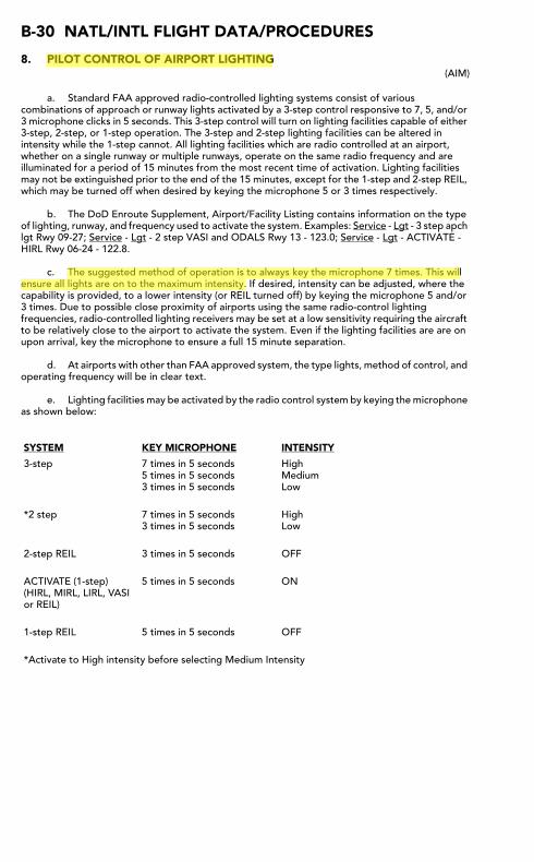
8. PILOT CONTROL OF AIRPORT LIGHTING(AIM)
a. Standard FAA approved radio-controlled lighting systems consist of various combinations of approach or runway lights activated by a 3-step control responsive to 7, 5, and/or 3 microphone clicks in 5 seconds. This 3-step control will turn on lighting facilities capable of either 3-step, 2-step, or 1-step operation. The 3-step and 2-step lighting facilities can be altered in intensity while the 1-step cannot. All lighting facilities which are radio controlled at an airport, whether on a single runway or multiple runways, operate on the same radio frequency and are illuminated for a period of 15 minutes from the most recent time of activation. Lighting facilities may not be extinguished prior to the end of the 15 minutes, except for the 1-step and 2-step REIL, which may be turned off when desired by keying the microphone 5 or 3 times respectively.
b. The DoD Enroute Supplement, Airport/Facility Listing contains information on the type of lighting, runway, and frequency used to activate the system. Examples: Service - Lgt - 3 step apch lgt Rwy 09-27; Service - Lgt - 2 step VASI and ODALS Rwy 13 - 123.0; Service - Lgt - ACTIVATE - HIRL Rwy 06-24 - 122.8.
c. The suggested method of operation is to always key the microphone 7 times. This will ensure all lights are on to the maximum intensity. If desired, intensity can be adjusted, where the capability is provided, to a lower intensity (or REIL turned off) by keying the microphone 5 and/or 3 times. Due to possible close proximity of airports using the same radio-control lighting frequencies, radio-controlled lighting receivers may be set at a low sensitivity requiring the aircraft to be relatively close to the airport to activate the system. Even if the lighting facilities are are on upon arrival, key the microphone to ensure a full 15 minute separation.
d. At airports with other than FAA approved system, the type lights, method of control, and operating frequency will be in clear text.
e. Lighting facilities may be activated by the radio control system by keying the microphone as shown below:
SYSTEM KEY MICROPHONE INTENSITY
3-step 7 times in 5 seconds5 times in 5 seconds3 times in 5 seconds
HighMediumLow
*2 step 7 times in 5 seconds3 times in 5 seconds
HighLow
2-step REIL 3 times in 5 seconds OFF
ACTIVATE (1-step) (HIRL, MIRL, LIRL, VASI or REIL)
5 times in 5 seconds ON
1-step REIL 5 times in 5 seconds OFF
*Activate to High intensity before selecting Medium Intensity
FTC
Highlight
FTC
Highlight

NATL/INTL FLIGHT DATA/PROCEDURES B-31
CUBIC
Rectangle
CUBIC
Rectangle
CUBIC
Rectangle
CUBIC
Rectangle
CUBIC
Rectangle

NATL/INTL FLIGHT DATA/PROCEDURES B-31
CUBIC
Rectangle
CUBIC
Rectangle
CUBIC
Rectangle
CUBIC
Rectangle

NATL/INTL FLIGHT DATA/PROCEDURES B-31
CUBIC
Rectangle
CUBIC
Rectangle
CUBIC
Rectangle

NATL/INTL FLIGHT DATA/PROCEDURES B-31
CUBIC
Rectangle
CUBIC
Rectangle
CUBIC
Rectangle

B-32 NATL/INTL FLIGHT DATA/PROCEDURES
CUBIC
Rectangle
CUBIC
Rectangle
CUBIC
Rectangle

CUBIC
Rectangle
CUBIC
Rectangle

NATL/INTL FLIGHT DATA/PROCEDURES B-33
CUBIC
Rectangle

CUBIC
Rectangle

B-38 NATL/INTL FLIGHT DATA/PROCEDURES
CUBIC
Rectangle
CUBIC
Rectangle

NATL/INTL FLIGHT DATA/PROCEDURES B-39

AIM 4/3/14
2−1−14 Airport Lighting Aids
a. With FAA approved systems, various combina-tions of medium intensity approach lights, runwaylights, taxiway lights, VASI and/or REIL may beactivated by radio control. On runways with bothapproach lighting and runway lighting (runway edgelights, taxiway lights, etc.) systems, the approachlighting system takes precedence for air−to−groundradio control over the runway lighting system whichis set at a predetermined intensity step, based onexpected visibility conditions. Runways withoutapproach lighting may provide radio controlledintensity adjustments of runway edge lights. Otherlighting systems, including VASI, REIL, and taxiwaylights may be either controlled with the runway edgelights or controlled independently of the runway edgelights.
b. The control system consists of a 3−step controlresponsive to 7, 5, and/or 3 microphone clicks. This3−step control will turn on lighting facilities capableof either 3−step, 2−step or 1−step operation. The3−step and 2−step lighting facilities can be altered inintensity, while the 1−step cannot. All lighting isilluminated for a period of 15 minutes from the mostrecent time of activation and may not be extinguishedprior to end of the 15 minute period (except for 1−stepand 2−step REILs which may be turned off whendesired by keying the mike 5 or 3 times respectively).
c. Suggested use is to always initially key the mike7 times; this assures that all controlled lights areturned on to the maximum available intensity. Ifdesired, adjustment can then be made, where thecapability is provided, to a lower intensity (or theREIL turned off) by keying 5 and/or 3 times. Due tothe close proximity of airports using the samefrequency, radio controlled lighting receivers may beset at a low sensitivity requiring the aircraft to berelatively close to activate the system. Consequently,even when lights are on, always key mike as directedwhen overflying an airport of intended landing or justprior to entering the final segment of an approach.This will assure the aircraft is close enough to activatethe system and a full 15 minutes lighting duration isavailable. Approved lighting systems may beactivated by keying the mike (within 5 seconds) asindicated in TBL 2−1−3.
TBL 2−1−3
Radio Control System
Key Mike Function
7 times within 5 seconds Highest intensity available
5 times within 5 seconds Medium or lower intensity(Lower REIL or REIL−off)
3 times within 5 seconds Lowest intensity available(Lower REIL or REIL−off)
d. For all public use airports with FAA standardsystems the Airport/Facility Directory contains thetypes of lighting, runway and the frequency that isused to activate the system. Airports with IAPsinclude data on the approach chart identifying thelight system, the runway on which they are installed,and the frequency that is used to activate the system.
NOTE−Although the CTAF is used to activate the lights at manyairports, other frequencies may also be used. Theappropriate frequency for activating the lights on theairport is provided in the Airport/Facility Directory andthe standard instrument approach procedures publica-tions. It is not identified on the sectional charts.
e. Where the airport is not served by an IAP, it mayhave either the standard FAA approved controlsystem or an independent type system of differentspecification installed by the airport sponsor. TheAirport/Facility Directory contains descriptions ofpilot controlled lighting systems for each airporthaving other than FAA approved systems, andexplains the type lights, method of control, andoperating frequency in clear text.
2−1−10. Airport/Heliport Beacons
a. Airport and heliport beacons have a verticallight distribution to make them most effective fromone to ten degrees above the horizon; however, theycan be seen well above and below this peak spread.The beacon may be an omnidirectional capacitor−dis-charge device, or it may rotate at a constant speedwhich produces the visual effect of flashes at regularintervals. Flashes may be one or two colorsalternately. The total number of flashes are:
1. 24 to 30 per minute for beacons markingairports, landmarks, and points on Federal airways.
2. 30 to 45 per minute for beacons markingheliports.
FTC
Highlight

AIM4/3/14
2−1−15Airport Lighting Aids
b. The colors and color combinations of beaconsare:
1. White and Green− Lighted land airport.
2. *Green alone− Lighted land airport.
3. White and Yellow− Lighted water airport.
4. *Yellow alone− Lighted water airport.
5. Green, Yellow, and White− Lighted heliport.
NOTE−*Green alone or yellow alone is used only in connectionwith a white−and−green or white−and−yellow beacondisplay, respectively.
c. Military airport beacons flash alternately whiteand green, but are differentiated from civil beaconsby dualpeaked (two quick) white flashes between thegreen flashes.
d. In Class B, Class C, Class D and Class E surfaceareas, operation of the airport beacon during the hoursof daylight often indicates that the ground visibilityis less than 3 miles and/or the ceiling is less than1,000 feet. ATC clearance in accordance with14 CFR Part 91 is required for landing, takeoff andflight in the traffic pattern. Pilots should not relysolely on the operation of the airport beacon toindicate if weather conditions are IFR or VFR. Atsome locations with operating control towers, ATCpersonnel turn the beacon on or off when controls arein the tower. At many airports the airport beacon isturned on by a photoelectric cell or time clocks andATC personnel cannot control them. There is noregulatory requirement for daylight operation and itis the pilot’s responsibility to comply with properpreflight planning as required by 14 CFRSection 91.103.
2−1−11. Taxiway Lights
a. Taxiway Edge Lights. Taxiway edge lights areused to outline the edges of taxiways during periodsof darkness or restricted visibility conditions. Thesefixtures emit blue light.
NOTE−At most major airports these lights have variable intensitysettings and may be adjusted at pilot request or whendeemed necessary by the controller.
b. Taxiway Centerline Lights. Taxiway center-line lights are used to facilitate ground traffic underlow visibility conditions. They are located along thetaxiway centerline in a straight line on straight
portions, on the centerline of curved portions, andalong designated taxiing paths in portions ofrunways, ramp, and apron areas. Taxiway centerlinelights are steady burning and emit green light.
c. Clearance Bar Lights. Clearance bar lightsare installed at holding positions on taxiways in orderto increase the conspicuity of the holding position inlow visibility conditions. They may also be installedto indicate the location of an intersecting taxiwayduring periods of darkness. Clearance bars consist ofthree in−pavement steady−burning yellow lights.
d. Runway Guard Lights. Runway guard lightsare installed at taxiway/runway intersections. Theyare primarily used to enhance the conspicuity oftaxiway/runway intersections during low visibilityconditions, but may be used in all weather conditions.Runway guard lights consist of either a pair ofelevated flashing yellow lights installed on either sideof the taxiway, or a row of in−pavement yellow lightsinstalled across the entire taxiway, at the runwayholding position marking.
NOTE−Some airports may have a row of three or five in−pavementyellow lights installed at taxiway/runway intersections.They should not be confused with clearance bar lightsdescribed in paragraph 2−1−11 c, Clearance Bar Lights.
e. Stop Bar Lights. Stop bar lights, wheninstalled, are used to confirm the ATC clearance toenter or cross the active runway in low visibilityconditions (below 1,200 ft Runway Visual Range). Astop bar consists of a row of red, unidirectional,steady−burning in−pavement lights installed acrossthe entire taxiway at the runway holding position, andelevated steady−burning red lights on each side. Acontrolled stop bar is operated in conjunction with thetaxiway centerline lead−on lights which extend fromthe stop bar toward the runway. Following the ATCclearance to proceed, the stop bar is turned off and thelead−on lights are turned on. The stop bar and lead−onlights are automatically reset by a sensor or backuptimer.
CAUTION−Pilots should never cross a red illuminated stop bar, evenif an ATC clearance has been given to proceed onto oracross the runway.
NOTE−If after crossing a stop bar, the taxiway centerline lead−onlights inadvertently extinguish, pilots should hold theirposition and contact ATC for further instructions.
FTC
Highlight
FTC
Highlight
FTC
Highlight

3-31
AIR FORCE TO 1T-6B-1NAVY NAVAIR A1-T6BAA-NFM-100
wing. If a fuel leak is suspected in flight, perform the follow-ing:
1. Aircraft structure - Visually inspect for signs of leak-age
IF LEAKING FUEL OVERBOARD:
2. FUEL BAL switch - MAN/RESET
3. MANUAL FUEL BAL switch - To non-leaking tank
The manual fuel balance switch may be left set to thenon-leaking tank for the duration of the flight to max-imize remaining fuel and endurance.
NOTE
With a full lateral fuel imbalance (one tankfull, the other tank empty), sufficient lateralauthority exists to control the aircraft (nocrosswind). Expect increased lateral stickforces.
4. MANUAL FUEL BAL switch - To leaking tank onceempty
5. Land as soon as possible
Fuel Probe Malfunction
1. Fuel gages and fuel flow - Verify indications
Do not attempt to manually balance fuel loadif FP FAIL caution is illuminated. With aprobe failure, a fuel imbalance message maynot be correct, and manual balancingattempts may cause or aggravate a fuel imbal-ance.
NOTE
• Depending on which probe malfunctions, thefuel quantity may read lower than actual. Arapid drop in fuel indication may occur.
• The auto fuel balance system will be inoper-ative, but the manual fuel balance systemremains operative.
2. EDM circuit breakers(left and right front console) - Check, reset if open
NOTE
The pilot should assess the severity of theemergency and equipment lost prior to reset-ting or opening any circuit breaker.
3. Land as soon as practical if fuel state cannot be veri-fied
HYDRAULIC SYSTEM MALFUNCTIONS
Normal operation of landing gear, flaps, speed brake, andnosewheel steering should be considered unavailable whenthe HYD FL LO caution is illuminated and pressure is below1800 psi, or when hydraulic pressure is rapidly decreasingtoward or reads 0 psi. If the hydraulic pressure transmitterfails, hydraulic pressure will read 0 psi or some other abnor-mal (out of normal operating limits) indication, but allhydraulic systems should operate normally. When theEHYD PX LO caution is illuminated, the emergency landinggear and flap extension system should be considered inoper-ative.
If the EHYD PX LO caution or the HYD FL LO caution illu-minates or hydraulic pressure drops below the normal oper-ating range, accomplish the following:
1. Hydraulic pressure - Check
NOTE
• Illumination of the EHYD PX LO caution orHYD FL LO caution may indicate a fluid leakin either hydraulic system. If the leak is on theemergency side and is of small enough flowrate that it does not activate the hydraulicfuse, all fluid could leak out of both systemsand a gear-up landing would be required.Unless fuel range is a factor, lower the gear(and flaps if desired) prior to depletion ofhydraulic fluid.
• Loss of hydraulic pressure (out of limits,decreasing toward, or reads, 0 psi) withoutillumination of either EHYD PX LO cautionor HYD FL LO caution may indicate engine-driven hydraulic pump failure or partial fail-ure.
• If HYD FL LO caution illuminates andhydraulic pressure indicates 0 psi, checkHYD SYS circuit breaker on the battery buscircuit breaker panel (left front console). Ifthe circuit breaker is open, it may be reset.
2. Airspeed - 150 KIAS or below
3. Landing gear handle - DOWN
NOTE
Low hydraulic pressure (below 1800 psi) willnecessitate using the emergency gear exten-sion procedure.
4. Flaps - Extend (as required)
CUBIC
Highlight
CUBIC
Highlight

3-32
AIR FORCE TO 1T-6B-1NAVY NAVAIR A1-T6BAA-NFM-100
NOTE
• Flap extension may require use of the emer-gency landing gear and flap extension systemif the normal hydraulic system pressure hasdropped below usable levels. If the emer-gency gear handle has not been pulled previ-ously to lower the landing gear, it will have tobe pulled in order to emergency extend theflaps.
• Landing gear and flap retraction is not possi-ble once extended using emergency landinggear extension system.
5. Land as soon as practical
RUDDER SYSTEM MALFUNCTION
The rudder may bind or jam for a variety of reasons. Rudderbinding/jamming incidents have been characterized by asudden restriction to rudder movement, in varying degrees ofseverity ranging from full rudder movement with “resis-tance” (binding) to a jammed rudder with minimal ruddermovement (jamming). Often the rudder ”releases” eitherwhile airborne or sometime during the landing or roll-out.
An out-of-trim rudder, caused by pilot input or TAD input,may be perceived by the pilot as a rudder system malfunc-tion. Re-trimming the rudder may alleviate the increasedrudder forces. Absent an actual mechanical malfunction, anout of trim rudder will still allow for full deflection of therudder at approach/landing airspeeds.
If rudder trim push rod failure is suspected, binding/jammingmay occur on internal components of the rudder trim system.This binding/jamming may cause control forces to exceednormal limits. With a rudder trim push rod failure the trimindications will respond to trim inputs but will have no effectupon rudder pedal forces or actual trim tab position.
In any case, movement of the rudder trim or rudder pedals inboth directions may eliminate the binding/jamming condi-tion and allow for easier controllability. If unable to elimi-nate the binding/jamming, changing the rudder pedalposition, bank angle, power, pitch attitude and/or airspeedmay relieve some excessive rudder forces. In all cases, usewhatever means available to maintain aircraft control.
With a jammed rudder, landing difficulty increases propor-tionally with an increase in crosswinds due to the inability toapply normal crosswind controls during approach, landingand roll-out. Differential braking may be required in order toprevent departure from the prepared surface.
1. Gear, flaps, speed brake - UP
2. Gust lock - Check Stowed
Failure to stow the gust lock completely mayprevent the flight controls from operatingproperly. Any attempt to actuate the flightcontrols with the gust lock not properlystowed may result in damage to the flightcontrol assemblies. Ensure the gust lock isnot impeded by the leather boot at the base ofthe control stick.
3. Climb to minimum 6500 ft AGL
NOTE
If necessary, relax rudder pedal force andallow heading to drift, controlling headingwith bank angle. If the aircraft turn and slipindicator is fully deflected, remain below 140KIAS. Consideration may be given to reduc-ing power to regain/maintain directional con-trol.
4. Airspeed - 120-140 KIAS
5. TAD switch - OFF
6. TRIM DISCONNECT switch - NORM (BOTH)
7. RUD TRIM circuit breaker (left front console) -CHECK; RESET IF OPEN
8. Rudder trim indicator/turn and slip indicator - Verifyindications (BOTH)
NOTE
A fully deflected cockpit rudder trim positionindicator may be indicative of a significantrudder mis-trim and/or a runaway rudder trimcondition.
9. Rudder trim - Move to achieve two ball widths deflec-tion as indicated on the trim slip indicator (wings-level, left and then right)
NOTE
With a rudder trim push rod failure, the cock-pit trim position indications will respond totrim inputs but will have no effect upon rud-der pedal forces, trim slip indicator or actualtrim tab position.
10. Rudder trim - Re-trim aircraft and verify the turn andslip indicator (ball) is centered, wings-level, withoutapplying any rudder pedal input/force.

CHAPTER ELEVEN TRANSITION TO LANDING AND MISSED APPROACH
1100. INTRODUCTION
The transition to the visual segment on an instrument approach begins once the field is in sight, and you are in a safe position to land.
1101. STRAIGHT-IN APPROACHES
On properly executed PAR, ASR, ILS/Localizer and most GPS approaches, the aircraft should be very close to being lined up on centerline when you gain visual reference to the runway environment. The transition, in this case, should be relatively simple. All that is normally required is an airspeed reduction and possible configuration change while continuing the descent from the DA/MDA to intercept a normal visual glidepath.
On some Non-Precision Straight-in approaches, the final approach course may be as much as 30º off runway heading. In this case, it will be necessary to continue on the final approach course until you can make a turn to line up on centerline.
Some Non-precision approaches have MDAs of 800’ or higher. If not depicted on the approach, a VDP should be calculated. Even if the runway is in sight, you should remain at the MDA until reaching the VDP before making a normal descent to the runway.
If the runway environment is not in sight until the MAP a descent from MDA to the normal touchdown zone could require an unsafe rate of descent. In this case a longer landing must be acceptable or a safe landing may not be possible. Remember, just because the runway environment is in sight at the MAP, does NOT mean a safe landing can be made.
1102. CIRCLING MANEUVERS
Description
Prior to commencing an approach that will end in a circling maneuver, a plan should be formulated on how the circle will take place. Consider the following:
1. Winds: Will they push the aircraft towards or away from the runway?
2. Runway alignment with respect to the approach being flown.
3. Airport environment: mountains, trees, towers, etc.
TRANSITION TO LANDING AND MISSED APPROACH 11-1
CUBIC
Highlight

CHAPTER ELEVEN PRIMARY INSTRUMENT NAVIGATION T-6B
Figure 11-1 Circling Maneuvers
Procedure
Upon breaking out of the weather, locate the intended runway in use. Remain at or above the circling altitude until the aircraft is in a position to land. Every effort should be made to fly normal VFR checkpoints (e.g., 180, 90, final).
11-2 TRANSITION TO LANDING AND MISSED APPROACH

PRIMARY INSTRUMENT NAVIGATION T-6B CHAPTER ELEVEN
NOTE
Normal checkpoints such as WTD may be different since you may be at either a higher or lower altitude than a normal pattern.
NOTE
Because of obstacles near the airport, a portion of the circling area may be restricted by a procedural note (e.g., “Circling NA E of RWY 17–35”). It is the pilot’s responsibility to review any circling restrictions for the intended airport. These restrictions can be found in the Approach Plates, AP1, IFR Supplement or current NOTAMs.
Circling Minimums
In some busy terminal areas, ATC may not allow circling and circling minimums will not be published. Published circling minimums provide obstacle clearance when pilots remain within the appropriate area of protection (see Figures 11-2 and 11-3).
NOTE
Where standard instrument approach procedures (SIAPs) authorize circling approaches, they provide a basic minimum of 300 feet of obstacle clearance at the MDA within the circling area considered.
When cleared for a circling maneuver, comply with any restrictions noted on the instrument approach procedure or any verbal instructions received from the controller.
When the direction of the circling maneuver in relation to the airport/runway is required, the controller will state the direction (eight cardinal compass points) and specify a left or right base/downwind leg as appropriate.
Pilots should remain at or above the circling altitude until the aircraft is continuously in a position from which a descent to a landing on the intended runway can be made at a normal rate of descent using normal maneuvers.
The following basic rules apply:
1. Unless otherwise instructed, maneuver the shortest path to the base or downwind leg, as appropriate, considering existing weather conditions. There is no restriction from passing over the airport or other runways.
2. It should be recognized that circling maneuvers may be made while VFR or other flying is in progress at the airport. Standard left turns or specific instruction from the controller for maneuvering must be considered when circling to land.
TRANSITION TO LANDING AND MISSED APPROACH 11-3
CUBIC
Highlight
CUBIC
Highlight

CHAPTER ELEVEN PRIMARY INSTRUMENT NAVIGATION T-6B
3. At airports without a control tower, it may be desirable to fly over the airport to observe wind and turn indicators and other traffic which may be on the runway or flying in the vicinity of the airport.
Figure 11-2 Circling Approach Area Radii
Charting Changes
Aeronautical charting providers have implemented new specifications to identify circle-to-land minima based on the new TERPS criteria. U.S. Terminal Procedures instrument approach charts use an “Inverse C” circle icon (see Figure 11-4) to identify circling radius minima based on the new criteria:
Circling MDA in feet MSL Approach Category and Circling Radius (NM)
CAT A CAT B CAT C CAT D CAT E 1000 or less 1.3 1.7 2.7 3.6 4.5 1001-3000 1.3 1.8 2.8 3.7 4.6 3001-5000 1.3 1.8 2.9 3.8 4.8 5001-7000 1.3 1.9 3.0 4.0 5.0 7001-9000 1.4 2.0 3.2 4.2 5.3 9001 and above 1.4 2.1 3.3 4.4 5.5
Figure 11-3 New Circling Area Radii
11-4 TRANSITION TO LANDING AND MISSED APPROACH
CUBIC
Highlight

PRIMARY INSTRUMENT NAVIGATION T-6B CHAPTER ELEVEN
Figure 11-4 U.S. Terminal Procedures Approach Charts – Circling Minima Based on (New) Larger Circling Areas
Missed Approach from a Circling Maneuver.
If visual reference is lost while circling-to-land from an instrument approach, the missed approach specified for that particular procedure must be followed (unless an alternate missed approach procedure is specified by ATC).
To become established on the prescribed missed approach course, the pilot should make an initial climbing turn toward the landing runway and continue the turn until established on the missed approach course (see Figure 11-5).
Making the initial turn toward the landing runway will help assure that an aircraft will remain laterally within the circling and missed approach obstruction clearance areas (see Figures 11-2 and 11-3).
Figure 11-5 Missed Approach from a Circling Maneuver
1103. MISSED APPROACH
Description
A Missed Approach is a procedure used to discontinue an instrument approach if the runway environment is not in sight, or the aircraft is not in a position to make a safe landing. The primary concern if unable to land is to climb to a safe altitude. Therefore, establishing and maintaining a positive rate of climb should be your first priority if a Missed Approach is commenced. Your second priority should be to turn the aircraft (if required) to intercept the Missed Approach course or to the designated heading.
TRANSITION TO LANDING AND MISSED APPROACH 11-5
CUBIC
Highlight