I3104 - T6B Driver · 1. Poor orientation, loss of SA. 2. Not setting the correct NAV source in the...
50
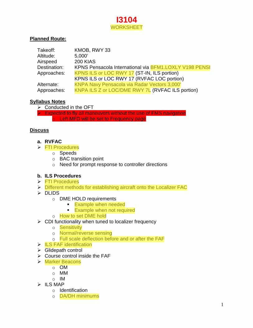
1 I3104 WORKSHEET Planned Route: Takeoff: KMOB, RWY 33 Altitude: 5,000’ Airspeed 200 KIAS Destination: KPNS Pensacola International via BFM1.LOXLY V198 PENSI Approaches: KPNS ILS or LOC RWY 17 (ST-IN, ILS portion) KPNS ILS or LOC RWY 17 (RVFAC LOC portion) Alternate: KNPA Navy Pensacola via Radar Vectors 3,000’ Approaches: KNPA ILS Z or LOC/DME RWY 7L (RVFAC ILS portion) Syllabus Notes Conducted in the OFT Expected to fly all maneuvers without the use of FMS navigation o Left MFD will be set to Frequency page Discuss a. RVFAC FTI Procedures o Speeds o BAC transition point o Need for prompt response to controller directions b. ILS Procedures FTI Procedures Different methods for establishing aircraft onto the Localizer FAC DLIDS o DME HOLD requirements Example when needed Example when not required o How to set DME hold CDI functionality when tuned to localizer frequency o Sensitivity o Normal/reverse sensing o Full scale deflection before and or after the FAF ILS FAF identification Glidepath control Course control inside the FAF Marker Beacons o OM o MM o IM ILS MAP o Identification o DA/DH minimums
Transcript of I3104 - T6B Driver · 1. Poor orientation, loss of SA. 2. Not setting the correct NAV source in the...
1
I3104 WORKSHEET
Planned Route:
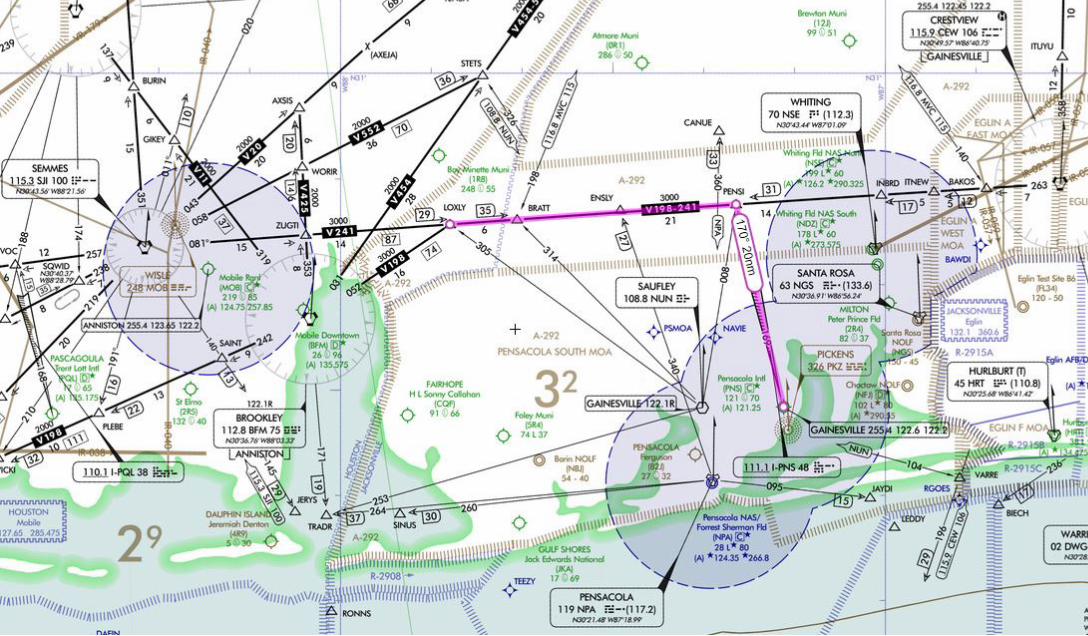
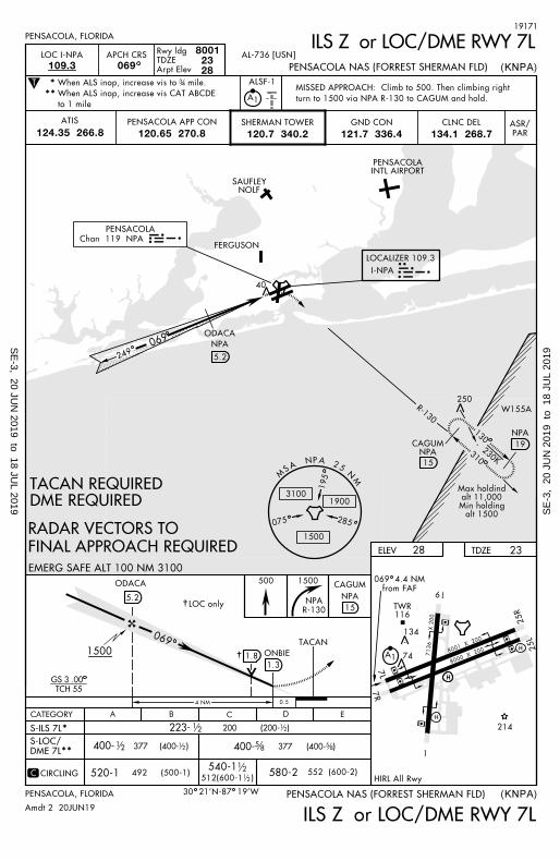
Takeoff: KMOB, RWY 33 Altitude: 5,000’ Airspeed 200 KIAS Destination: KPNS Pensacola International via BFM1.LOXLY V198 PENSI Approaches: KPNS ILS or LOC RWY 17 (ST-IN, ILS portion) KPNS ILS or LOC RWY 17 (RVFAC LOC portion) Alternate: KNPA Navy Pensacola via Radar Vectors 3,000’ Approaches: KNPA ILS Z or LOC/DME RWY 7L (RVFAC ILS portion)
Syllabus Notes Conducted in the OFT Expected to fly all maneuvers without the use of FMS navigation
o Left MFD will be set to Frequency page Discuss
a. RVFAC FTI Procedures
o Speeds o BAC transition point o Need for prompt response to controller directions
b. ILS Procedures FTI Procedures Different methods for establishing aircraft onto the Localizer FAC DLIDS
o DME HOLD requirements Example when needed Example when not required
o How to set DME hold CDI functionality when tuned to localizer frequency
o Sensitivity o Normal/reverse sensing o Full scale deflection before and or after the FAF
ILS FAF identification Glidepath control Course control inside the FAF Marker Beacons
o OM o MM o IM
ILS MAP o Identification o DA/DH minimums
FTC
Cross-Out
CUBIC
Highlight
CUBIC
Highlight
CUBIC
Highlight
CUBIC
Highlight
CUBIC
Highlight
CUBIC
Highlight
CUBIC
Highlight
CUBIC
Highlight
CUBIC
Highlight
CUBIC
Highlight
CUBIC
Highlight
CUBIC
Highlight
CUBIC
Highlight
CUBIC
Highlight
CUBIC
Highlight
CUBIC
Highlight
CUBIC
Highlight

2
c. LOC Procedures FTI Procedures Differences from ILS Procedures
o LOC FAF Identification o Minimums o LOC MAP
d. Fuel system malfunctions
CUBIC
Highlight
CUBIC
Highlight
CUBIC
Highlight
CUBIC
Highlight
CUBIC
Highlight

T-6B Radio Instruments I3100 Block STUDENT GRADE SHEET DATE __________________ INSTRUCTOR __________________________ MEDIA: OFT VT- ________ BRIEF TIME: ________ NAME: ________________________________ EVENT:__________
# MANEUVER MIF I3101 I3102 I3103 I3104 I3105 13106 1 GENERAL KNOWLEDGE / PROCEDURES 3+ X X X X X X 2 EMERGENCY PROCEDURES 3+ X X X X X X 3 HEADWORK / SITUATIONAL AWARENESS 3+ X X X X X X 4 BASIC AIRWORK 3+ X X X X X X 5 IN-FLIGHT CHECKS / FUEL MANAGEMENT 3+ X X X X X X 6 IN-FLIGHT PLANNING/AREA ORIENTATION 3 7 TASK MANAGEMENT 3+ X X X X X X 8 COMMUNICATION 3+ X X X X X X 9 MISSION PLANNING/BRIEFING/DEBRIEFING 3+ X X X X X X 10 GROUND OPERATIONS 4 11 TAKEOFF 4+ X X X X X X 12 DEPARTURE 3+ X X X X X X 44 RADIAL INTERCEPTS 3+ X X X 45 POINT-TO-POINT 3+ X 49 HOLDING 2+ X X X X 50 ENROUTE PROCEDURES 2+ X X X X X X 51 ENROUTE DESCENT 2+ X X X X X X 52 HIGH-ALTITUDE APPROACH 2 53 TEARDROP APPROACH 2+ X 54 ARCING APPROACH 2+ X 55 HILO APPROACH 2+ X 56 PROCEDURE TURN APPROACH 2+ X 57 RVFAC APPROACH 2+ X 58 GPS APPROACH 2 59 PAR APPROACH 2+ X 60 ASR APPROACH 2+ X 61 VOR FINAL 2+ X X X 62 ILS FINAL 2+ X X 63 LOC FINAL 2+ X X 64 GPS FINAL 2 65 BACKUP FLIGHT INSTRUMENT APPROACH 2 66 CIRCLING APPROACH 2 67 MISSED APPROACH 2+ X X X X X X 68 TRANSITION TO LANDING / LANDING 3
NOTES: I3105 AND I3106 shall be under simulated night conditions. I3101-3 may be conducted in the UDT. During this phase of training, the student will be expected to fly all maneuvers without the use of FMS navigation. I3101 and I3102 shall only be scheduled as one event per day. DISCUSS ITEMS: I3101: Clearance and departure procedures, VOR procedure turn and teardrop approaches, 6T’s, FAF-to-MAP timing adjustments, VDP, and missed approach. I3102: Holding, HILO approaches, oil system malfunctions, shuttle descent, and intersections. I3103: PAR, ASR, IMC emergencies, and propeller malfunctions. I3104: RVFAC, ILS/LOC procedures, and fuel system malfunctions. I3105: Arcing, night procedures, night lighting, night cockpit setup, and hydraulics system malfunctions. I3106: SID / STAR, obstacle departure procedure, Trouble T, and obtaining IFR clearance from uncontrolled airports. DEPART ______________ ARRIVE ______________ SIDE # ______________ SIM TIME ___________
JPPT 1542.166B Rev 03/30/2017
FTC
Highlight
FTC
Highlight
FTC
Highlight
FTC
Highlight
FTC
Highlight
FTC
Highlight
CUBIC
Highlight
CUBIC
Highlight
CUBIC
Highlight
CUBIC
Highlight
CUBIC
Highlight
CUBIC
Highlight
CUBIC
Highlight
CUBIC
Highlight
CUBIC
Highlight
CUBIC
Highlight
CUBIC
Highlight
CUBIC
Highlight
CUBIC
Highlight

(BFM1.LOXLY) TC-003 (CUBIC) BROOKLEY ONE DEPARTURE
ATIS 124.75 257.85
MOBILE RGNL (MOB) MOBILE, ALABAMA
CLNC DEL 119.85 GND CON 121.9 348.6 MOBILE TOWER 118.3 (CTAF) 239.0 MOBILE APP CON 118.5 269.3 UNICOM 122.95
SIMULATOR USE ONLY Note: Chart not to scale
DEPARTURE ROUTE DESCRIPTION
TAKEOFF RWY 15: Climb to 800 then climbing right turn to 3000 on heading 200° and SJI VORTAC R-140 to SAINT then BFM VORTAC R-242 to BFM then BFM VORTAC R-052 to LOXLEY Thence….
TAKEOFF RWY 33: Climb via heading 330° to 3000, then right turn heading 140°and SJI VORTAC R-081 to LOXLY Thence….
….Maintain 5000 or ATC assigned altitude. Expect clearance to filed altitude 10 minutes after departure.
BROOKLEY ONE DEPARTURE MOBILE, ALABAMA (BFM1.LOXLY) 8 JUN 18 MOBILE RGNL (MOB)
TAKEOFF OBSTACLE NOTES: Rwy 15: Tree 1758' from DER, 886' right of centerline 79' AGL/270' MSL. Tree 1987' from DER, 856' left of centerline, 73' AGL/277' MSL. Tree 2102' from DER, 861' right of centerline, 78' AGL/269' MSL. Tree 2131' from DER, left of centerline, 76' AGL/280' MSL.
TOP ALTITUDE: 5000
BFM
Chan 100
3100
SEMMES • • • • ‒ ‒ ‒ • •
SIMULATOR USE ONLY
115.3 SJI
N30°43.56’ W88°21.56’ L-22, H-6, H-8
SAINT
BROOKLEY ‒ • • • • • ‒ • ‒ ‒
112.8 BFM Chan 75 N30°36.76’ W88°03.33’
L-22, H-6, H-8
R-081 LOXLY

201TWR
0.3
% U
P
P
P
P
P
A5
A5
8
26
7000 X 15
0
7004 X 1
50
35
17
(8.4)04
9°1800
R-269
269°
089°
034°214°
349°
Chan 48
I-PNS
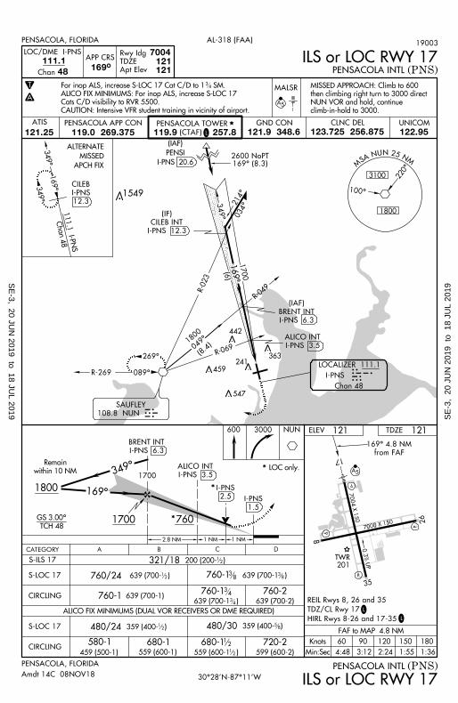
LOCALIZER 111.1IPNS
T
ELEV
MALSR
111.1
48169°
7004121121
359 (400- )480/24
720-2
599 (600-2)
S-LOC 17
CIRCLING
1800
Remain
within 10 NM
GS 3.00° 1700
1700349
°
600 3000 NUN
1.5
I-PNS
121
ATIS
A
121.25
PENSACOLA APP CON
119.0 269.375
GND CON
121.9 348.6
CLNC DEL
123.725 256.875PENSACOLA TOWER
(CTAF)119.9 257.8L
108.8 NUN
SAUFLEY
L
from FAF
169° 4.8 NM
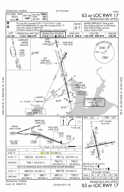
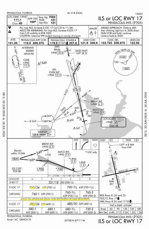
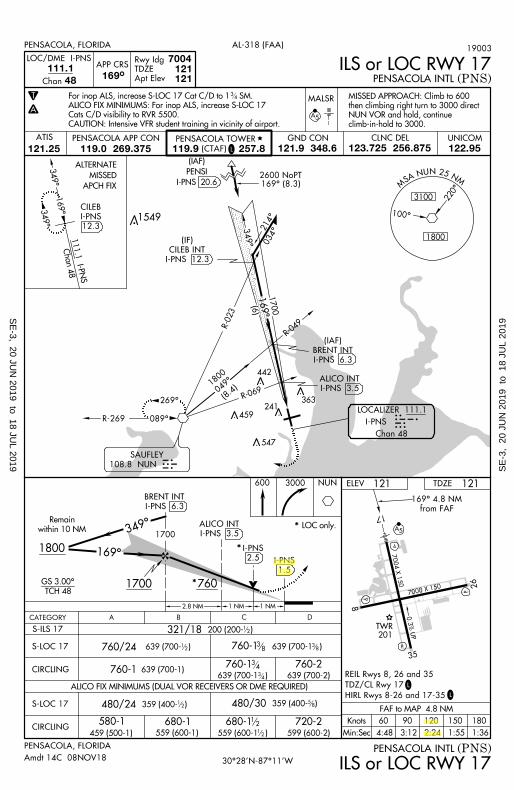
PENSACOLA, FLORIDA AL-318 (FAA)
(PNS)
(PNS)PENSACOLA, FLORIDA
ILS or LOC RWY 17
ILS or LOC RWY 17
TDZE 121
321/18
639 (700- )760/24 760-1
760-1 639 (700-1)760-1
639 (700-1 )
760-2
639 (700-2)
S-ILS 17
S-LOC 17
CIRCLING
359 (400- )480/30 58
639 (700-1 )38
38
34
34
MSA
NUN25NM
3100
1800
220°
I-PNS 6.3
BRENT INT
I-PNS 3.5
ALICO INT
2.5
I-PNS
LOC only.*
*
*760
2.8 NM 1 NM
1801501209060Knots
Min:Sec
FAF to MAP 4.8 NM
4:48 3:12 2:24 1:55 1:36
169°
I-PNS 12.3
CILEB INT
(IF)
I-PNS 3.5
ALICO INT
1 NM
R-0
23
R-04
9
R-069
(6)
1700
169°
Chan 4
8111.1 I-P
NS
APCH FIX
MISSED
ALTERNATE349°
169°349°
UNICOM
122.95
ALICO FIX MINIMUMS (DUAL VOR RECEIVERS OR DME REQUIRED)
NUN
169° (8.3)2600 NoPT
12
19003
100°
I-PNS 6.3
BRENT INT
(IAF)
PENSACOLA INTL
PENSACOLA INTL
30°28'N-87°11'W
I-PNS 20.6
PENSI
(IAF)
Apt Elev
TDZE
Rwy Idg
HIRL Rwys 8-26 and 17-35
TDZ/CL Rwy 17
REIL Rwys 8, 26 and 35
climb-in-hold to 3000.
NUN VOR and hold, continue
then climbing right turn to 3000 direct
MISSED APPROACH: Climb to 600
APP CRSLOC/DME I-PNS
Chan
C DBCATEGORY A
200 (200- )12
680-112
12
12
L
12.3
I-PNS
CILEB
580-1
459 (500-1)
680-1559 (600-1) 559 (600-1 )
TCH 48
547
459
442
363241
1549
34
Amdt 14C 08NOV18
CAUTION: Intensive VFR student training in vicinity of airport.
Cats C/D visibility to RVR 5500.
ALICO FIX MINIMUMS: For inop ALS, increase S-LOC 17
For inop ALS, increase S-LOC 17 Cat C/D to 1 SM.
SE
-3, 20 JUN
2019 to 18 JUL 2019 S
E-3
, 20
JU
N 2
019
to 1
8 JU
L 20
19
SE
-3, 20 JUN
2019 to 18 JUL 2019 S
E-3
, 20
JU
N 2
019
to 1
8 JU
L 20
19

CHAPTER EIGHT PRIMARY INSTRUMENT NAVIGATION T-6B
819. RADAR VECTORS TO FINAL APPROACH COURSE (RVFAC)
General
Navigate to the final approach course following controller instructions.
Description
Radar vectors to final approach course is a procedure used by approach control to increase the arrival rate of aircraft by providing vectors onto the final approach course through the most expeditious routes consistent with traffic situations.
Although this routing does expedite arrival at your destination, it has one characteristic of which you should be aware – the lack of published minimum altitudes until joining a segment of a published approach. Approach control has the statutory responsibility for ensuring terrain clearance while vectoring you for the approach. This is done using Minimum Vectoring Altitude (MVA) charts superimposed on radar displays.
NOTE
Pilots should never fully relinquish the responsibility for terrain clearance to an outside agency. Maintain situational awareness and crosscheck terrain clearance altitude by using available NAVAIDS and charts. Never blindly follow vectors from a controller. Be aware of what lies ahead on your assigned heading. If in doubt, query the controller.
Procedure
Fly 200 KIAS on downwind and 150 KIAS on base. If being vectored on an extended final or extended dog-leg to final, maintain 200 KIAS until within 15 NM of the airport (Figure 8-16).
1. Tune and identify the appropriate NAVAID.
2. Check the PFD is configured properly.
3. Set the final approach course into the CDI.
4. Follow radar vectors given by approach control.
5. If a lower altitude is assigned, perform a terminal descent.
6. Transition to BAC:
a. When within 5 NM of the FAF and aircraft heading is within 90º of the final
approach course.
8-32 TERMINAL PROCEDURES
CUBIC
Highlight
PRIMARY INSTRUMENT NAVIGATION T-6B CHAPTER EIGHT
b. Once established on the FAC and cleared for the approach if no FAF is depicted.
7. When cleared for the approach, maintain the last assigned altitude and heading given by ATC until established on the approach. As the CDI begins to center, and you are cleared for the approach, you are expected to turn onto the final approach course and track inbound.
8. Once established inbound, comply with the remainder of the Low Altitude Instrument Approach Procedures.
Common Errors
1. Poor orientation, loss of SA.
2. Not setting the correct NAV source in the PFD.
3. Failure to transition to BAC at the appropriate time.
4. Failure to intercept the approach course once cleared for the approach. Be alert for CDI movement and lead the turn sufficiently to roll out on course.
Figure 8-16 RVFAC (FAF Depicted)
TERMINAL PROCEDURES 8-33
Extended Straight-in 200 KIAS until 15 nm from airport
Extended Dog-Leg to final 200 KIAS until 15 nm from airport
Base leg 150 KIAS
*Transition to BAC when 5 nm from the FAF and aircraft heading is within 90° of the FAC
*If no FAF is depicted, transition to BAC when established on FAC and cleared for the approach
Downwind 200 KIAS
PRIMARY INSTRUMENT NAVIGATION T-6B CHAPTER NINE
Procedure
Comply with the appropriate “Transition Procedure” to establish the aircraft onto or near the Localizer course. Pilots should tune the VHF NAV receiver to identify and monitor the localizer identification signal as soon as practical during the transition procedure. D LIDS is an effective memory aid for setting up the ILS or LOC approach.
Use Figure 9-2 for the following example where the aircraft is on downwind, being radar vectored to final for the ILS approach to runway 22L at KLFT. One of the advantages of radar vectors to final for the ILS or LOC approach is the VHF NAV is free to be set up well in advance of final.
1. As soon as practical (prior to localizer interception), set NAVAIDS. Perform D LIDS check.
D - DME Hold - Set (N/A in this example. DME is provided from the localizer’s paired
frequency Chan 32)
L - Localizer Frequency - Tune, ID and monitor (I-LFT 109.5)
I - Inbound Course - Set CDI to FAC (front course 216°)
D - Display - Set PFD Source to LOC
S - Speed - Appropriate for transition procedure (RVFAC downwind 200 KIAS)
2. Transition to BAC in accordance with the associated transition procedure.
Methods for determining 5 nm from the ILS FAF
a. DME (not all ILS approaches provide DME)
b. ATD from a GPS waypoint (from an approved FMS database)
c. Controller provided radar identification
d. Established at the published glideslope intercept altitude and the glideslope indication is “alive” (green diamond first starts to move down from the top of the glideslope scale on the PFD).
Alternate method for BAC transition: Set descent power (24%) within 5 nm of the FAF and allow the aircraft to slow towards 120 KIAS. Transition to BAC once the glideslope diamond indicates 1 ½ to 1 dot prior to glideslope intercept. If this transition is timed well, the aircraft will reach 120 KIAS as the glideslope is intercepted and the descent will require only small power changes from the FAF to the MAP.
FINAL APPROACH PROCEDURES 9-13
CUBIC
Highlight
CHAPTER NINE PRIMARY INSTRUMENT NAVIGATION T-6B
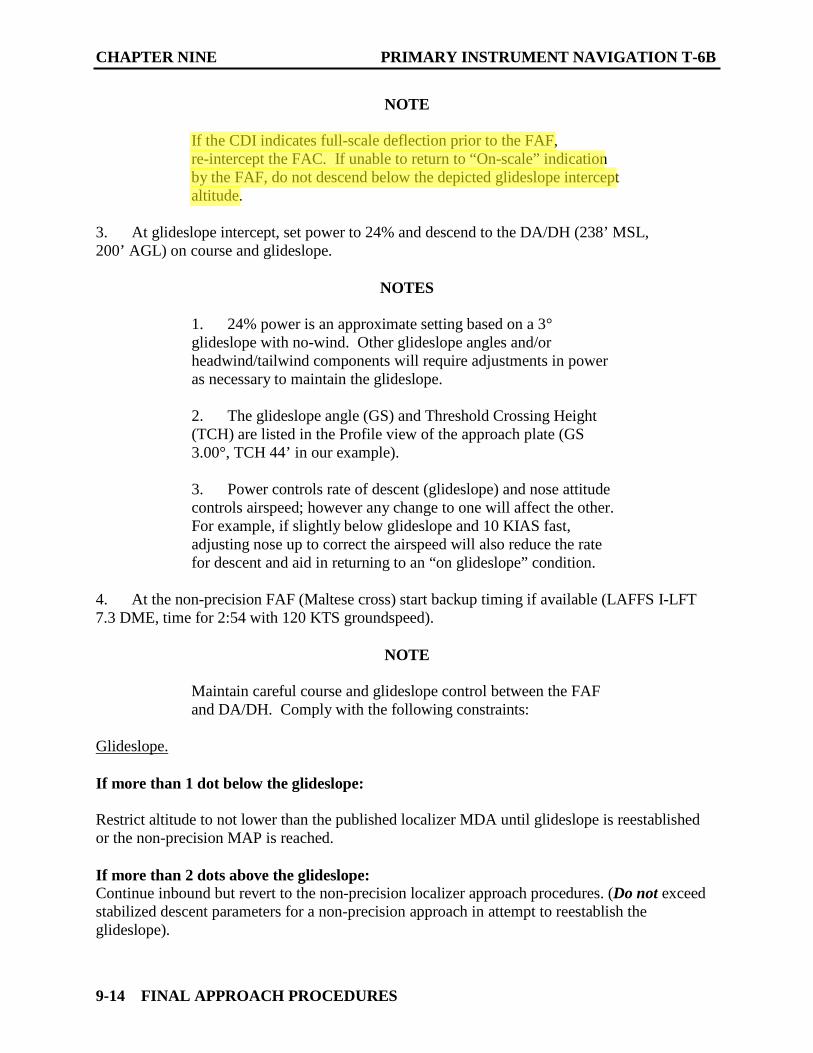
NOTE
If the CDI indicates full-scale deflection prior to the FAF, re-intercept the FAC. If unable to return to “On-scale” indication by the FAF, do not descend below the depicted glideslope intercept altitude.
3. At glideslope intercept, set power to 24% and descend to the DA/DH (238’ MSL,200’ AGL) on course and glideslope.
NOTES
1. 24% power is an approximate setting based on a 3°glideslope with no-wind. Other glideslope angles and/or headwind/tailwind components will require adjustments in power as necessary to maintain the glideslope.
2. The glideslope angle (GS) and Threshold Crossing Height(TCH) are listed in the Profile view of the approach plate (GS 3.00°, TCH 54’ in our example).
3. Power controls rate of descent (glideslope) and nose attitudecontrols airspeed; however any change to one will affect the other. For example, if slightly below glideslope and 10 KIAS fast, adjusting nose up to correct the airspeed will also reduce the rate for descent and aid in returning to an “on glideslope” condition.
4. At the non-precision FAF (Maltese cross) start backup timing if available (LAFFS I-LFT7.3 DME, time for 2:57 with 120 KTS groundspeed).
NOTE
Maintain careful course and glideslope control between the FAF and DA/DH. Comply with the following constraints:
Glideslope.
If more than 1 dot below the glideslope:
Restrict altitude to not lower than the published localizer MDA until glideslope is reestablished or the non-precision MAP is reached.
If more than 2 dots above the glideslope: Continue inbound but revert to the non-precision localizer approach procedures. (Do not exceed stabilized descent parameters for a non-precision approach in attempt to reestablish the glideslope).
9-14 FINAL APPROACH PROCEDURES
PRIMARY INSTRUMENT NAVIGATION T-6B CHAPTER NINE
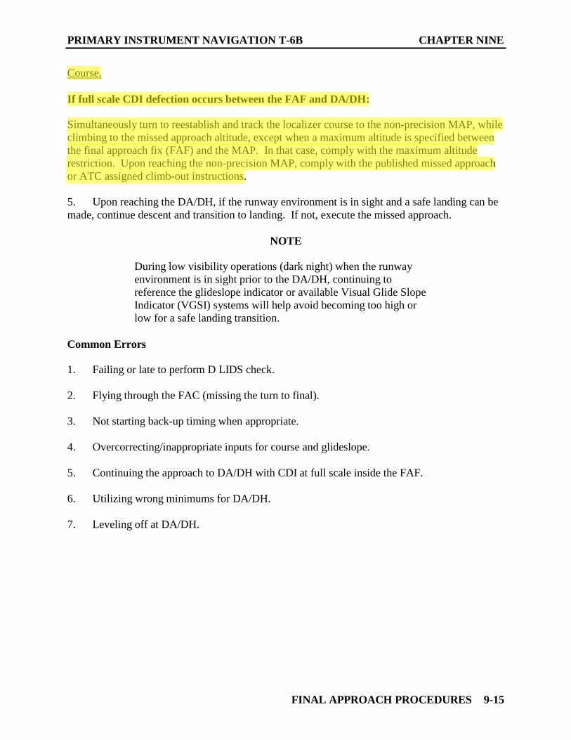
Course.
If full scale CDI defection occurs between the FAF and DA/DH:
Simultaneously turn to reestablish and track the localizer course to the non-precision MAP, while climbing to the missed approach altitude, except when a maximum altitude is specified between the final approach fix (FAF) and the MAP. In that case, comply with the maximum altitude restriction. Upon reaching the non-precision MAP, comply with the published missed approach or ATC assigned climb-out instructions.
5. Upon reaching the DA/DH, if the runway environment is in sight and a safe landing can be made, continue descent and transition to landing. If not, execute the missed approach.
NOTE
During low visibility operations (dark night) when the runway environment is in sight prior to the DA/DH, continuing to reference the glideslope indicator or available Visual Glide Slope Indicator (VGSI) systems will help avoid becoming too high or low for a safe landing transition.
Common Errors
1. Failing or late to perform D LIDS check.
2. Flying through the FAC (missing the turn to final).
3. Not starting back-up timing when appropriate.
4. Overcorrecting/inappropriate inputs for course and glideslope.
5. Continuing the approach to DA/DH with CDI at full scale inside the FAF.
6. Utilizing wrong minimums for DA/DH.
7. Leveling off at DA/DH.
FINAL APPROACH PROCEDURES 9-15
T-6B PRIMARY INSTRUMENT NAVIGATION CHAPTER NINE
FINAL APPROACH PROCEDURES 9-7
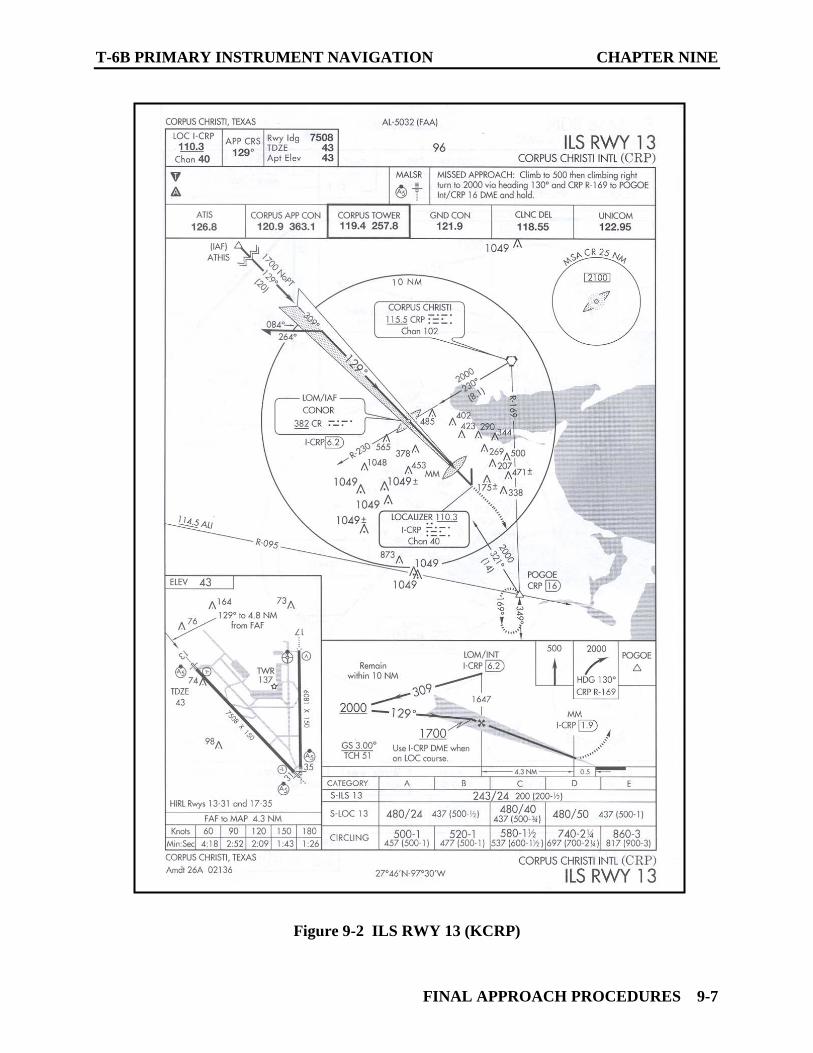
Figure 9-2 ILS RWY 13 (KCRP)
PRIMARY INSTRUMENT NAVIGATION T-6B CHAPTER NINE
903. LOCALIZER APPROACH
General
A localizer approach is a non-precision approach that utilizes the localizer component of the ILS system to provide accurate course guidance to the runway centerline. The process of establishing the aircraft onto the FAC and localizer characteristics are exactly the same as those discussed for the ILS approach.
Once established on the final approach course, the procedures closely reflect those used for other non-precision approaches.
On approaches titled ILS or LOC, where the glideslope information is not used, or is unavailable, non-precision rules and minimums apply.
Procedure
Comply with the appropriate “Transition Procedure” to establish the aircraft onto or near the Localizer course. Pilots should tune the VHF NAV receiver to identify and monitor the localizer identification signal as soon as practical during the transition procedure. D LIDS is an effective memory aid for setting up the ILS or LOC approach.
Use Figure 9-3 for the following example; assume the aircraft is on downwind, being radar vectored to final for the LOC/DME approach to runway 13R at KNGP. One of the advantages of radar vectors to final for the ILS or LOC approach is the VHF NAV is free to be set up well in advance of final.
1. As soon as practical (prior to localizer interception), set NAVAIDS. Perform D LIDS check.
D - DME Hold - Set (114.0 in this example. DME is provided from the TRUAX VORTAC).
L - Localizer Frequency - Tune, ID and monitor (I-NGP 111.3)
I - Inbound Course - Set CDI to FAC (129°)
D - Display - Set PFD Source to LOC
S - Speed - Appropriate for transition procedure (RVFAC Downwind 200 KIAS)
Comply with the appropriate transition procedure until established on the localizer final.
2. Transition to BAC in accordance with the appropriate transition procedure.
FINAL APPROACH PROCEDURES 9-17
FTC
Highlight
CHAPTER NINE PRIMARY INSTRUMENT NAVIGATION T-6B
NOTE
If CDI indicates full-scale deflection prior to the FAF, re-intercept the FAC. If unable to return to “On-scale” indication by the FAF, do not descent below the FAF altitude.
3. At the non-precision FAF (Maltese cross at GEMJO I-NGP 5.7 DME) perform the 6 Ts:
a. TIME - Start timing. (Will be needed as a back-up to ID the MAP in the event of
DME failure.)
b. TURN - As required to continue tracking the localizer course.
c. TIME - Not required.
d. TRANSITION - Set approximately 15% torque, trim for 120 KIAS descent to next segment altitude or MDA, as required.
NOTE
Adjust pitch to maintain airspeed; use power as required to maintain a stabilized rate of descent not to exceed 1000 fpm.
e. TWIST - Ensure Front course is set in the CDI, continue tracking.
NOTE
If full scale CDI defection occurs between the FAF and the MAP, simultaneously turn to reestablish and track the localizer course to the non-precision MAP, while climbing to the missed approach altitude, except when a maximum altitude is specified between the final approach fix (FAF) and the MAP. In that case, comply with the maximum altitude restriction. Upon reaching the non-precision MAP, comply with the published missed approach or ATC assigned climb-out instructions.
f. TALK - Give appropriate voice report if required.
4. Approximately 100’ prior to the LOC MDA (360’ MSL) - set approximately 42% torque and transition to level flight at or above MDA. Continue tracking to the MAP (I-NGP 1.4 DME, backed-up with 2:09 timing).
5. If runway environment is in sight and a safe landing can be made, maneuver to land. If not, execute the missed approach.
9-18 FINAL APPROACH PROCEDURES
PRIMARY INSTRUMENT NAVIGATION T-6B CHAPTER NINE
Common Errors
1. Failing or late to perform D LIDS check.
2. Flying through the FAC.
3. Not starting back-up timing when appropriate.
4. Overcorrecting/inappropriate inputs for course.
5. Continuing the approach to MDA with CDI at full scale inside the FAF.
6. Utilizing wrong minimums for MDA.
7. Executing missed approach upon reaching MDA vice waiting for MAP.
904. BACK COURSE LOCALIZER APPROACH (LOC BC)
Description
A variant of the LOC approach is the LOC-BC or “back course” approach. Localizer antennae are positioned at the opposite end of the runway from the front course approach direction and are aligned with the runway centerline. Every localizer transmitter radiates a signal in two directions, one being the “front course” and the other being the “back course.” For example, the localizer antenna for an ILS system for RWY 26 (FAC 260°), would be located off the approach end of RWY 8. It radiates a front course for RWY 26. The back course radiates for RWY 8. If an IAP has been charted for this back course, then you can fly it just as you would a LOC approach, with one important exception: You must set the front course in the CDI. If the front course is not used, the CDI will give reverse sensing.
Procedure
Comply with the appropriate “Transition Procedure” to establish the aircraft onto or near the Localizer course. Pilots should tune the VHF NAV receiver to identify and monitor the localizer identification signal as soon as practical during the transition procedure. D LIDS is an effective memory aid for setting up the ILS or LOC approach.
Use Figure 9-4 for the following example where the aircraft is executing the LOC BC approach to runway 16 at KCLL from IAF YOBUR. In this case the CLL VOR will be required for the arcing maneuver until just prior to the localizer final.
1. As soon as practical, perform D LIDS check. (The lead radial LR-344 would be useful in determining when to start D-LIDS.)
D - DME Hold - Set (N/A in this example. DME is provided from the I-CLL paired frequency, Chan 42(Y).)
FINAL APPROACH PROCEDURES 9-19

Instrument Landing System (ILS) Due to the narrow nature of the localizer course, an aircraft must be within 2.5° of its centerline before useful course information can be displayed in the cockpit. While Radar Vectors to the Final Approach course is the most common method used to establish the aircraft on a localizer course, other IAPs may also be used. In this example the feeder route from the SAUFLEY VOR could be flown until receiving the localizer at BRENT IAF. Then, the Localizer based course could be used to fly a Procedure Turn (PT) maneuver to establish the aircraft inbound to the FAF. The CDI must be set to 169° for both the outbound and inbound legs to ensure Normal Sensing.

Instrument Landing System (ILS) This IAP has multiple options for transitioning onto the Localizer final: • IAF WIREGRASS VORTAC-Teardrop (TD) • IAFs IVGIF/ZUTAG-Arcing (ARC) • IAF OALDY-Straight-In (St-In) • Radar Vector to Final (RVFAC)
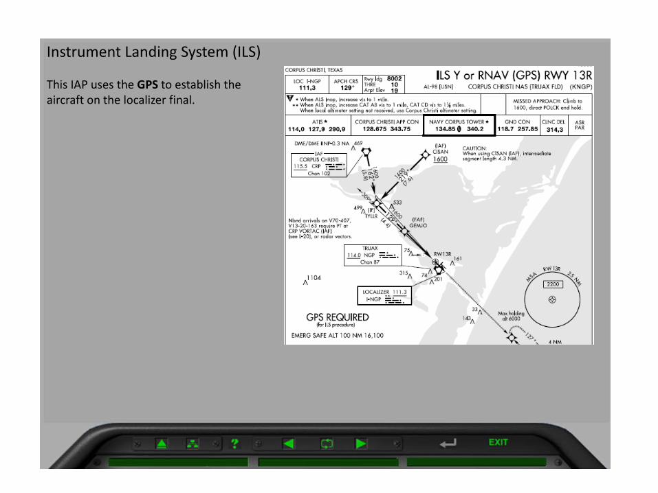
Instrument Landing System (ILS) This IAP uses the GPS to establish the aircraft on the localizer final.
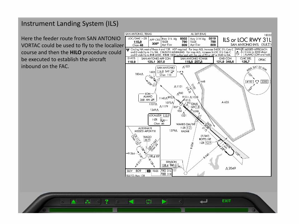
Instrument Landing System (ILS) Here the feeder route from SAN ANTONIO VORTAC could be used to fly to the localizer course and then the HILO procedure could be executed to establish the aircraft inbound on the FAC.

CHAPTER NINE PRIMARY INSTRUMENT NAVIGATION T-6B
Examples:
Figure 9-2 ILS RWY 22L (KLFT):
1. Feeder fix LFT, 035° Course at 2100’ until established on the localizer, I-LFT, then to IAF LAFFS for the Procedure Turn approach (PT).
2. Direct to LAFFS IAF using the GPS until established on the localizer then using the Procedure Turn approach (PT) or using the GPS during the PT until turning inbound.
3. Straight-In approach from BEDDY.
Figure 9-2a ILS or LOC RWY 32 (KDHN)
1. IAF OALDY, Heading, 271° at 2600’ until established on the localizer I-DHN.
2. IAF RRS, for the Teardrop approach (TD).
3. IAFs IVGIF or ZUTAG, for the Arcing approach.
Figure 9-2b ILS Z or RNAV (GPS) RWY 14 (KNSE)
1. IAF MERTY, for the “Holding-in-lieu of Procedure Turn” (HILO) approach.
2. IAF PENSI, for the GPS approach.
System characteristics
When a localizer frequency is tuned into the VHF NAV, several differences exist from when a VOR station is tuned.
1. PFD Source option of LOC becomes available (VOR option is removed).
2. When the PFD Source is selected to LOC, the localizer Course/Glidepath scales will appear on the PFD. When a good signal is being received, the associate Course/Glidepath marker (Green Diamonds) will appear.
3. The Morse code identifier will consist of four letters, of which the first letter will always be “I”.
4. The CDI will be 4 times more sensitive than the VOR (1.25° per dot, 2.5° full scale).
9-10 FINAL APPROACH PROCEDURES
CUBIC
Highlight
CUBIC
Highlight
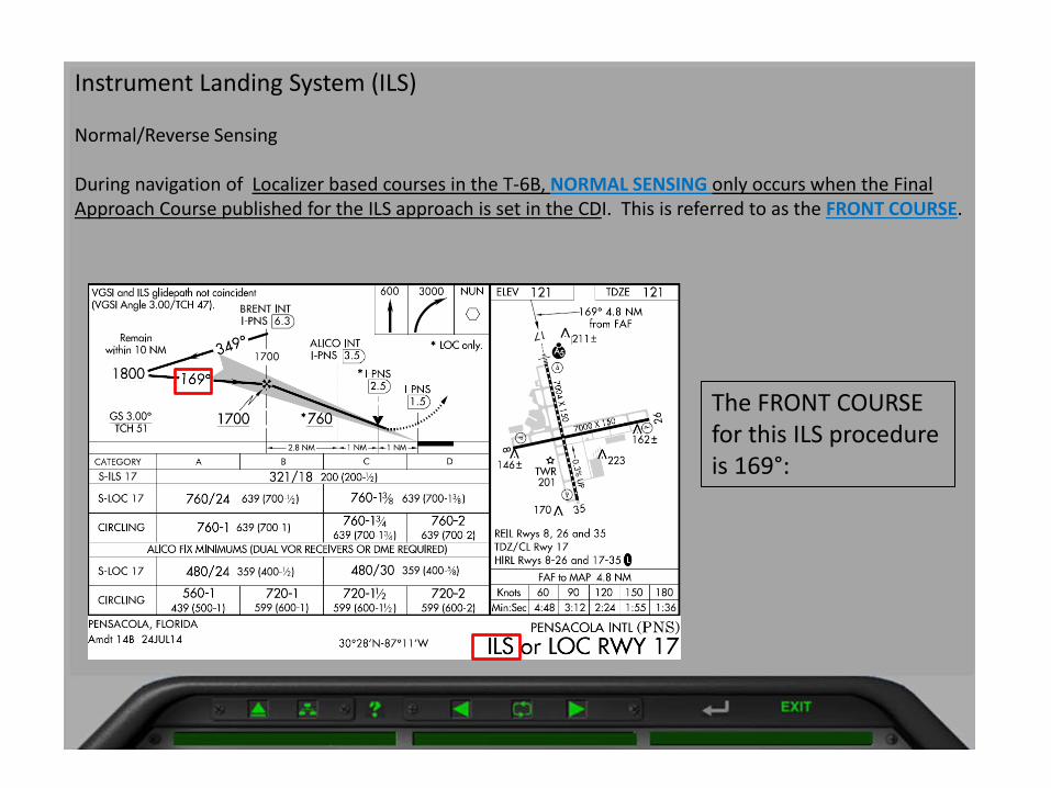
Instrument Landing System (ILS) Normal/Reverse Sensing During navigation of Localizer based courses in the T-6B, NORMAL SENSING only occurs when the Final Approach Course published for the ILS approach is set in the CDI. This is referred to as the FRONT COURSE.
The FRONT COURSE for this ILS procedure is 169°:
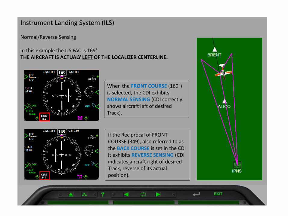
Instrument Landing System (ILS) Normal/Reverse Sensing In this example the ILS FAC is 169°. THE AIRCRAFT IS ACTUALY LEFT OF THE LOCALIZER CENTERLINE.
When the FRONT COURSE (169°) is selected, the CDI exhibits NORMAL SENSING (CDI correctly shows aircraft left of desired Track).
If the Reciprocal of FRONT COURSE (349), also referred to as the BACK COURSE is set in the CDI it exhibits REVERSE SENSING (CDI indicates aircraft right of desired Track, reverse of its actual position).
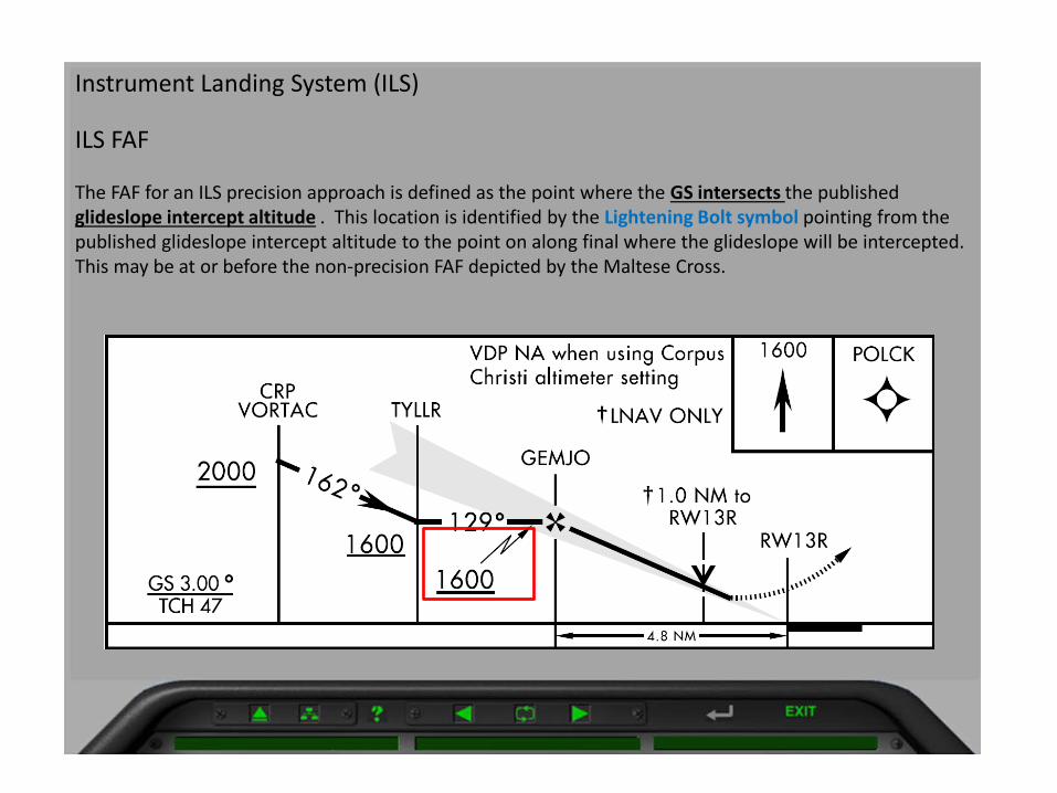
Instrument Landing System (ILS) ILS FAF The FAF for an ILS precision approach is defined as the point where the GS intersects the published glideslope intercept altitude . This location is identified by the Lightening Bolt symbol pointing from the published glideslope intercept altitude to the point on along final where the glideslope will be intercepted. This may be at or before the non-precision FAF depicted by the Maltese Cross.
FTC
Typewritten Text
Figure 9-2e ILS FAF coincides with non-precision FAF.
CUBIC
Highlight

Instrument Landing System (ILS) ILS FAF Where an altitude is depicted above the Maltese Cross, it represents the MSL altitude that should be observed by an aircraft that is “On” the glideslope crossing that point. Checking this will ensure you have not captured a “False Glideslope”.
CHAPTER NINE PRIMARY INSTRUMENT NAVIGATION T-6B
NOTE
If the CDI indicates full-scale deflection prior to the FAF, re-intercept the FAC. If unable to return to “On-scale” indication by the FAF, do not descend below the depicted glideslope intercept altitude.
3. At glideslope intercept, set power to 24% and descend to the DA/DH (238’ MSL, 200’ AGL) on course and glideslope.
NOTES
1. 24% power is an approximate setting based on a 3° glideslope with no-wind. Other glideslope angles and/or headwind/tailwind components will require adjustments in power as necessary to maintain the glideslope.
2. The glideslope angle (GS) and Threshold Crossing Height (TCH) are listed in the Profile view of the approach plate (GS 3.00°, TCH 44’ in our example).
3. Power controls rate of descent (glideslope) and nose attitude controls airspeed; however any change to one will affect the other. For example, if slightly below glideslope and 10 KIAS fast, adjusting nose up to correct the airspeed will also reduce the rate for descent and aid in returning to an “on glideslope” condition.
4. At the non-precision FAF (Maltese cross) start backup timing if available (LAFFS I-LFT 7.3 DME, time for 2:54 with 120 KTS groundspeed).
NOTE
Maintain careful course and glideslope control between the FAF and DA/DH. Comply with the following constraints:
Glideslope.
If more than 1 dot below the glideslope:
Restrict altitude to not lower than the published localizer MDA until glideslope is reestablished or the non-precision MAP is reached.
If more than 2 dots above the glideslope: Continue inbound but revert to the non-precision localizer approach procedures. (Do not exceed stabilized descent parameters for a non-precision approach in attempt to reestablish the glideslope).
9-14 FINAL APPROACH PROCEDURES
CUBIC
Highlight
PRIMARY INSTRUMENT NAVIGATION T-6B CHAPTER NINE
Course.
If full scale CDI defection occurs between the FAF and DA/DH:
Simultaneously turn to reestablish and track the localizer course to the non-precision MAP, while climbing to the missed approach altitude, except when a maximum altitude is specified between the final approach fix (FAF) and the MAP. In that case, comply with the maximum altitude restriction. Upon reaching the non-precision MAP, comply with the published missed approach or ATC assigned climb-out instructions.
5. Upon reaching the DA/DH, if the runway environment is in sight and a safe landing can be made, continue descent and transition to landing. If not, execute the missed approach.
NOTE
During low visibility operations (dark night) when the runway environment is in sight prior to the DA/DH, continuing to reference the glideslope indicator or available Visual Glide Slope Indicator (VGSI) systems will help avoid becoming too high or low for a safe landing transition.
Common Errors
1. Failing or late to perform D LIDS check.
2. Flying through the FAC (missing the turn to final).
3. Not starting back-up timing when appropriate.
4. Overcorrecting/inappropriate inputs for course and glideslope.
5. Continuing the approach to DA/DH with CDI at full scale inside the FAF.
6. Utilizing wrong minimums for DA/DH.
7. Leveling off at DA/DH.
FINAL APPROACH PROCEDURES 9-15
FTC
Typewritten Text
FTC
Typewritten Text
FTC
Typewritten Text
CUBIC
Highlight

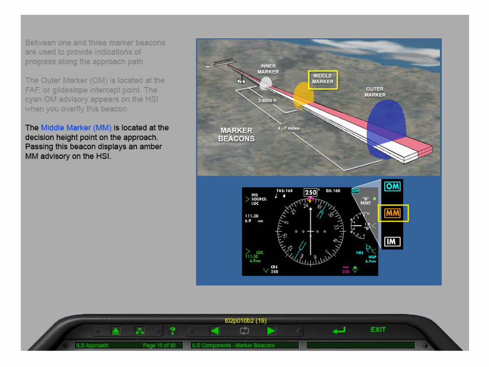
Instrument Landing System (ILS) Range Information Marker Beacons Ordinarily, there are two marker beacons associated with an ILS, the OM and MM. Locations with a Category II ILS also have an Inner Marker (IM). The T-6B VHF NAV system includes a marker beacon receiver tuned to the common marker beacon frequency of 75.00 Mhz. When an aircraft passes over a marker beacon, the pilot will receive audio and visual indications as follows:
FTC
Highlight
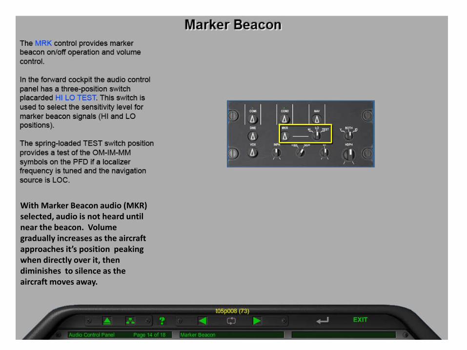
With Marker Beacon audio (MKR) selected, audio is not heard until near the beacon. Volume gradually increases as the aircraft approaches it’s position peaking when directly over it, then diminishes to silence as the aircraft moves away.


PRIMARY INSTRUMENT NAVIGATION T-6B CHAPTER NINE
Course.
If full scale CDI defection occurs between the FAF and DA/DH:
Simultaneously turn to reestablish and track the localizer course to the non-precision MAP, while climbing to the missed approach altitude, except when a maximum altitude is specified between the final approach fix (FAF) and the MAP. In that case, comply with the maximum altitude restriction. Upon reaching the non-precision MAP, comply with the published missed approach or ATC assigned climb-out instructions.
5. Upon reaching the DA/DH, if the runway environment is in sight and a safe landing can be made, continue descent and transition to landing. If not, execute the missed approach.
NOTE
During low visibility operations (dark night) when the runway environment is in sight prior to the DA/DH, continuing to reference the glideslope indicator or available Visual Glide Slope Indicator (VGSI) systems will help avoid becoming too high or low for a safe landing transition.
Common Errors
1. Failing or late to perform D LIDS check.
2. Flying through the FAC (missing the turn to final).
3. Not starting back-up timing when appropriate.
4. Overcorrecting/inappropriate inputs for course and glideslope.
5. Continuing the approach to DA/DH with CDI at full scale inside the FAF.
6. Utilizing wrong minimums for DA/DH.
7. Leveling off at DA/DH.
FINAL APPROACH PROCEDURES 9-15
CUBIC
Highlight
201TWR
0.3
% U
P
P
P
P
P
A5
A5
8
26
7000 X 15
0
7004 X 1
50
35
17
(8.4)04
9°1800
R-269
269°
089°
034°214°
349°
Chan 48
I-PNS
LOCALIZER 111.1IPNS
T
ELEV
MALSR
111.1
48169°
7004121121
359 (400- )480/24
720-2
599 (600-2)
S-LOC 17
CIRCLING
1800
Remain
within 10 NM
GS 3.00° 1700
1700349
°
600 3000 NUN
1.5
I-PNS
121
ATIS
A
121.25
PENSACOLA APP CON
119.0 269.375
GND CON
121.9 348.6
CLNC DEL
123.725 256.875PENSACOLA TOWER
(CTAF)119.9 257.8L
108.8 NUN
SAUFLEY
L
from FAF
169° 4.8 NM
PENSACOLA, FLORIDA AL-318 (FAA)
(PNS)
(PNS)PENSACOLA, FLORIDA
ILS or LOC RWY 17
ILS or LOC RWY 17
TDZE 121
321/18
639 (700- )760/24 760-1
760-1 639 (700-1)760-1
639 (700-1 )
760-2
639 (700-2)
S-ILS 17
S-LOC 17
CIRCLING
359 (400- )480/30 58
639 (700-1 )38
38
34
34
MSA
NUN25NM
3100
1800
220°
I-PNS 6.3
BRENT INT
I-PNS 3.5
ALICO INT
2.5
I-PNS
LOC only.*
*
*760
2.8 NM 1 NM
1801501209060Knots
Min:Sec
FAF to MAP 4.8 NM
4:48 3:12 2:24 1:55 1:36
169°
I-PNS 12.3
CILEB INT
(IF)
I-PNS 3.5
ALICO INT
1 NM
R-0
23
R-04
9
R-069
(6)
1700
169°
Chan 4
8111.1 I-P
NS
APCH FIX
MISSED
ALTERNATE349°
169°349°
UNICOM
122.95
ALICO FIX MINIMUMS (DUAL VOR RECEIVERS OR DME REQUIRED)
NUN
169° (8.3)2600 NoPT
12
19003
100°
I-PNS 6.3
BRENT INT
(IAF)
PENSACOLA INTL
PENSACOLA INTL
30°28'N-87°11'W
I-PNS 20.6
PENSI
(IAF)
Apt Elev
TDZE
Rwy Idg
HIRL Rwys 8-26 and 17-35
TDZ/CL Rwy 17
REIL Rwys 8, 26 and 35
climb-in-hold to 3000.
NUN VOR and hold, continue
then climbing right turn to 3000 direct
MISSED APPROACH: Climb to 600
APP CRSLOC/DME I-PNS
Chan
C DBCATEGORY A
200 (200- )12
680-112
12
12
L
12.3
I-PNS
CILEB
580-1
459 (500-1)
680-1559 (600-1) 559 (600-1 )
TCH 48
547
459
442
363241
1549
34
Amdt 14C 08NOV18
CAUTION: Intensive VFR student training in vicinity of airport.
Cats C/D visibility to RVR 5500.
ALICO FIX MINIMUMS: For inop ALS, increase S-LOC 17
For inop ALS, increase S-LOC 17 Cat C/D to 1 SM.
SE
-3, 20 JUN
2019 to 18 JUL 2019 S
E-3
, 20
JU
N 2
019
to 1
8 JU
L 20
19
CUBIC
Highlight
CUBIC
Highlight
CUBIC
Highlight
CUBIC
Highlight
CUBIC
Highlight
3-30
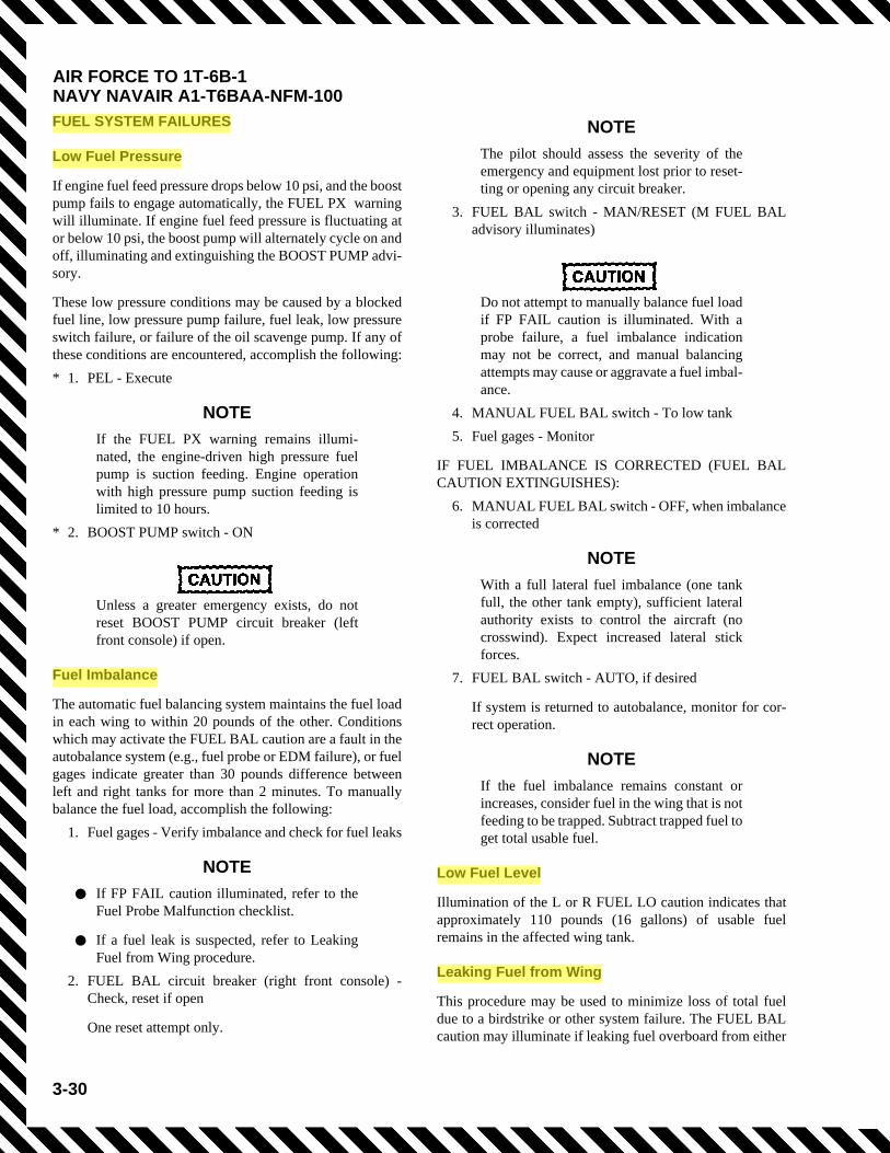
AIR FORCE TO 1T-6B-1NAVY NAVAIR A1-T6BAA-NFM-100FUEL SYSTEM FAILURES
Low Fuel Pressure
If engine fuel feed pressure drops below 10 psi, and the boostpump fails to engage automatically, the FUEL PX warningwill illuminate. If engine fuel feed pressure is fluctuating ator below 10 psi, the boost pump will alternately cycle on andoff, illuminating and extinguishing the BOOST PUMP advi-sory.
These low pressure conditions may be caused by a blockedfuel line, low pressure pump failure, fuel leak, low pressureswitch failure, or failure of the oil scavenge pump. If any ofthese conditions are encountered, accomplish the following:* 1. PEL - Execute
NOTE
If the FUEL PX warning remains illumi-nated, the engine-driven high pressure fuelpump is suction feeding. Engine operationwith high pressure pump suction feeding islimited to 10 hours.
* 2. BOOST PUMP switch - ON
Unless a greater emergency exists, do notreset BOOST PUMP circuit breaker (leftfront console) if open.
Fuel Imbalance
The automatic fuel balancing system maintains the fuel loadin each wing to within 20 pounds of the other. Conditionswhich may activate the FUEL BAL caution are a fault in theautobalance system (e.g., fuel probe or EDM failure), or fuelgages indicate greater than 30 pounds difference betweenleft and right tanks for more than 2 minutes. To manuallybalance the fuel load, accomplish the following:
1. Fuel gages - Verify imbalance and check for fuel leaks
NOTE
• If FP FAIL caution illuminated, refer to theFuel Probe Malfunction checklist.
• If a fuel leak is suspected, refer to LeakingFuel from Wing procedure.
2. FUEL BAL circuit breaker (right front console) -Check, reset if open
One reset attempt only.
NOTE
The pilot should assess the severity of theemergency and equipment lost prior to reset-ting or opening any circuit breaker.
3. FUEL BAL switch - MAN/RESET (M FUEL BALadvisory illuminates)
Do not attempt to manually balance fuel loadif FP FAIL caution is illuminated. With aprobe failure, a fuel imbalance indicationmay not be correct, and manual balancingattempts may cause or aggravate a fuel imbal-ance.
4. MANUAL FUEL BAL switch - To low tank5. Fuel gages - Monitor
IF FUEL IMBALANCE IS CORRECTED (FUEL BALCAUTION EXTINGUISHES):
6. MANUAL FUEL BAL switch - OFF, when imbalanceis corrected
NOTE
With a full lateral fuel imbalance (one tankfull, the other tank empty), sufficient lateralauthority exists to control the aircraft (nocrosswind). Expect increased lateral stickforces.
7. FUEL BAL switch - AUTO, if desired
If system is returned to autobalance, monitor for cor-rect operation.
NOTE
If the fuel imbalance remains constant orincreases, consider fuel in the wing that is notfeeding to be trapped. Subtract trapped fuel toget total usable fuel.
Low Fuel Level
Illumination of the L or R FUEL LO caution indicates thatapproximately 110 pounds (16 gallons) of usable fuelremains in the affected wing tank.
Leaking Fuel from Wing
This procedure may be used to minimize loss of total fueldue to a birdstrike or other system failure. The FUEL BALcaution may illuminate if leaking fuel overboard from either
CUBIC
Highlight
CUBIC
Highlight
CUBIC
Highlight
CUBIC
Highlight
CUBIC
Highlight
3-31
AIR FORCE TO 1T-6B-1NAVY NAVAIR A1-T6BAA-NFM-100
wing. If a fuel leak is suspected in flight, perform the follow-ing:
1. Aircraft structure - Visually inspect for signs of leak-age
IF LEAKING FUEL OVERBOARD:2. FUEL BAL switch - MAN/RESET3. MANUAL FUEL BAL switch - To non-leaking tank
The manual fuel balance switch may be left set to thenon-leaking tank for the duration of the flight to max-imize remaining fuel and endurance.
NOTE
With a full lateral fuel imbalance (one tankfull, the other tank empty), sufficient lateralauthority exists to control the aircraft (nocrosswind). Expect increased lateral stickforces.
4. MANUAL FUEL BAL switch - To leaking tank onceempty
5. Land as soon as possible
Fuel Probe Malfunction
1. Fuel gages and fuel flow - Verify indications
Do not attempt to manually balance fuel loadif FP FAIL caution is illuminated. With aprobe failure, a fuel imbalance message maynot be correct, and manual balancingattempts may cause or aggravate a fuel imbal-ance.
NOTE
• Depending on which probe malfunctions, thefuel quantity may read lower than actual. Arapid drop in fuel indication may occur.
• The auto fuel balance system will be inoper-ative, but the manual fuel balance systemremains operative.
2. EDM circuit breakers(left and right front console) - Check, reset if open
NOTE
The pilot should assess the severity of theemergency and equipment lost prior to reset-ting or opening any circuit breaker.
3. Land as soon as practical if fuel state cannot be veri-fied
HYDRAULIC SYSTEM MALFUNCTIONS
Normal operation of landing gear, flaps, speed brake, andnosewheel steering should be considered unavailable whenthe HYD FL LO caution is illuminated and pressure is below1800 psi, or when hydraulic pressure is rapidly decreasingtoward or reads 0 psi. If the hydraulic pressure transmitterfails, hydraulic pressure will read 0 psi or some other abnor-mal (out of normal operating limits) indication, but allhydraulic systems should operate normally. When theEHYD PX LO caution is illuminated, the emergency landinggear and flap extension system should be considered inoper-ative.
If the EHYD PX LO caution or the HYD FL LO caution illu-minates or hydraulic pressure drops below the normal oper-ating range, accomplish the following:
1. Hydraulic pressure - Check
NOTE
• Illumination of the EHYD PX LO caution orHYD FL LO caution may indicate a fluid leakin either hydraulic system. If the leak is on theemergency side and is of small enough flowrate that it does not activate the hydraulicfuse, all fluid could leak out of both systemsand a gear-up landing would be required.Unless fuel range is a factor, lower the gear(and flaps if desired) prior to depletion ofhydraulic fluid.
• Loss of hydraulic pressure (out of limits,decreasing toward, or reads, 0 psi) withoutillumination of either EHYD PX LO cautionor HYD FL LO caution may indicate engine-driven hydraulic pump failure or partial fail-ure.
• If HYD FL LO caution illuminates andhydraulic pressure indicates 0 psi, checkHYD SYS circuit breaker on the battery buscircuit breaker panel (left front console). Ifthe circuit breaker is open, it may be reset.
2. Airspeed - 150 KIAS or below3. Landing gear handle - DOWN
NOTE
Low hydraulic pressure (below 1800 psi) willnecessitate using the emergency gear exten-sion procedure.
4. Flaps - Extend (as required)
CUBIC
Highlight
CUBIC
Highlight
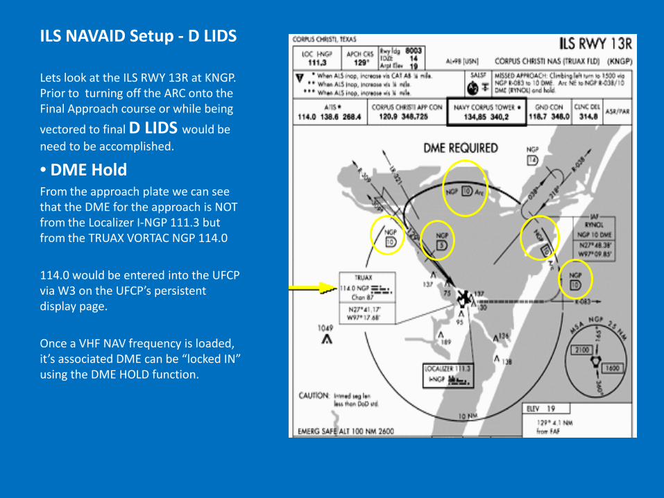
ILS NAVAID Setup - D LIDS
Lets look at the ILS RWY 13R at KNGP. Prior to turning off the ARC onto the Final Approach course or while being
vectored to final D LIDS would be need to be accomplished.
• DME Hold From the approach plate we can see that the DME for the approach is NOT from the Localizer I-NGP 111.3 but from the TRUAX VORTAC NGP 114.0 114.0 would be entered into the UFCP via W3 on the UFCP’s persistent display page. Once a VHF NAV frequency is loaded, it’s associated DME can be “locked IN” using the DME HOLD function.

ILS NAVAID Setup - D LIDS
On the UFCP press the NAV TUNE button until the DME page is displayed along with the NAVAID frequency you wish to HOLD

ILS NAVAID Setup - D LIDS
On the UFCP press the NAV TUNE button until the DME page is displayed along with the NAVAID frequency you wish to HOLD Press the W2 button to activate the DME Hold function. This will be indicated by an (H) following the frequency. (The (H) can be toggled on/off using the W2 button) Once set, the DME will remain referenced from this NAVAID until the (H) is removed.

ILS NAVAID Setup - D LIDS
•Localizer Set Using the UFCP return to the persistent display page and load the Localizer frequency I-NGP 111.3 into W3.
•Inbound Course Set the FAC into the CDI

ILS NAVAID Setup - D LIDS
•DISPLAY Ensure that PFD Source is set to LOC
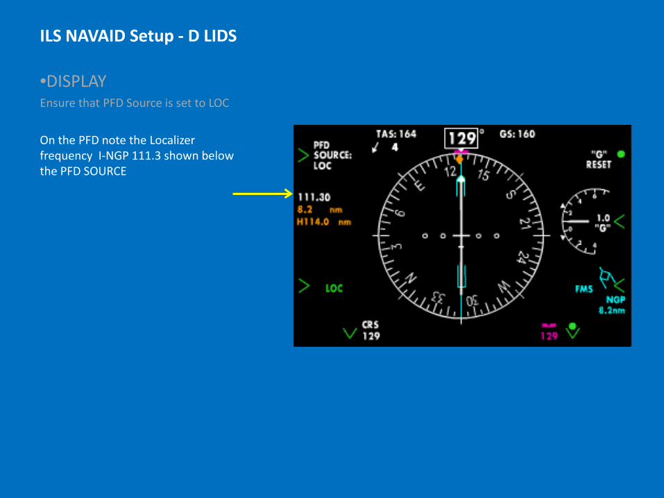
ILS NAVAID Setup - D LIDS
•DISPLAY Ensure that PFD Source is set to LOC On the PFD note the Localizer frequency I-NGP 111.3 shown below the PFD SOURCE
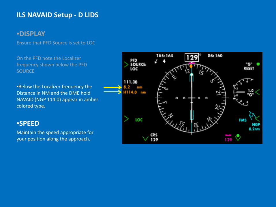
ILS NAVAID Setup - D LIDS
•DISPLAY Ensure that PFD Source is set to LOC
On the PFD note the Localizer frequency shown below the PFD SOURCE •Below the Localizer frequency the Distance in NM and the DME hold NAVAID (NGP 114.0) appear in amber colored type.
•SPEED Maintain the speed appropriate for your position along the approach.

Localizer Approaches Localizer FAF Recall that the Localizer transmitter provides only course (Azimuth) information. Because glideslope information will not be available/used, this will constitute a Non-Precision Approach. The Localizer (non-precision) FAF will occur at the depicted Maltese Cross. This point may be identified by: • DME (from the localizer or other
NAVAID)
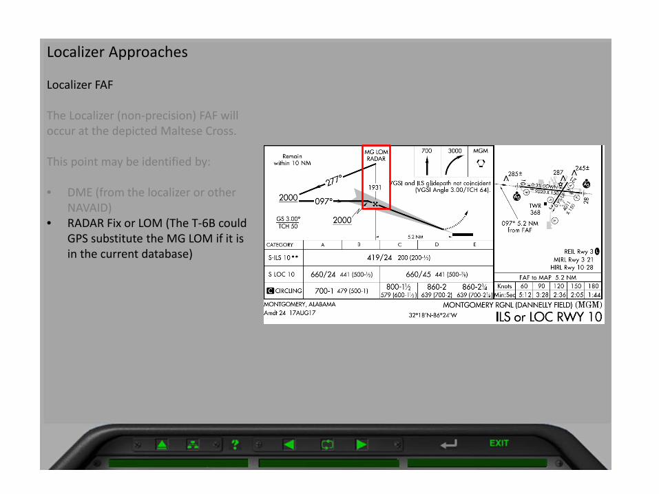
Localizer Approaches Localizer FAF The Localizer (non-precision) FAF will occur at the depicted Maltese Cross. This point may be identified by:
• DME (from the localizer or other
NAVAID) • RADAR Fix or LOM (The T-6B could
GPS substitute the MG LOM if it is in the current database)

Localizer Approaches Localizer FAF The Localizer (non-precision) FAF will occur at the depicted Maltese Cross. This point may be identified by:
• DME (from the localizer or other
NAVAID) • RADAR Fix or LOM (The T-6B could
GPS substitute the MG LOM if it is in the current database)
• GPS Waypoint
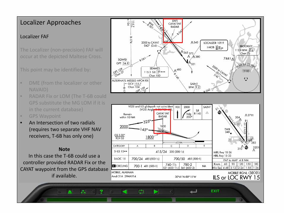
Localizer Approaches Localizer FAF The Localizer (non-precision) FAF will occur at the depicted Maltese Cross. This point may be identified by:
• DME (from the localizer or other
NAVAID) • RADAR Fix or LOM (The T-6B could
GPS substitute the MG LOM if it is in the current database)
• GPS Waypoint • An Intersection of two radials
(requires two separate VHF NAV receivers, T-6B has only one)
Note In this case the T-6B could use a
controller provided RADAR Fix or the CAYAT waypoint from the GPS database
if available.