i03329120 Installing the 266-8480 Temperature Control Kit ...
12
Special Instruction Installing the 266-8480 Temperature Control Kit (Manual) on 300 Series B Excavators {7304} Installing the 266-8480 Temperature Control Kit (Manual) on 300 Series B Excavators{7304} SMCS - 7304 Excavator: 320B (S/N: 7JR1-878; 1XS1-633; 2AS1-570; 5MS1-318; 9WS1-178; 6LW1-233; 3YZ1-UP) 322B (S/N: 1YS1-761; 2ES1-403) 325B (S/N: 6DN1-632; 8FN1-511; 2JR1-1740,1741-1742; 4DS1-157; 5BS1-219) 330B (S/N: 3YR1-611; 5LR1-353; 6DR1-2009; 4RS1-360; 5LS1-210) Introduction This Special Instruction details the procedures to be used in order to replace the electronic components in the Heater or Air Conditioner Groups for the listed machines. Do not perform any procedure that is outlined in this publication, or order any parts until you have read the information in this publication. Refer to the appropriate Parts Manual, Operation and Maintenance Manual, and Service Manual for your machine. Required Parts Shutdown SIS Previous Screen Product: EXCAVATOR Model: 330B L EXCAVATOR 6DR Configuration: 330B L Excavator 6DR00001-UP (MACHINE) POWERED BY 3306 Engine Media Number -REHS2618-02 Publication Date -17/10/2008 Date Updated -17/10/2008 i03329120 Table 1 Required Parts Item Quantity Part Number 1 1 266-8480 Kit (Manual Controls) 2 1 205-4285 Electrical Converter Gp Page 1 of 25 330B L Excavator 6DR00001-UP (MACHINE) POWERED BY 3306 Engine(SEBP2437... 6/5/2010 https://sisweb.cat.com/sisweb/sisweb/techdoc/techdoc_print_page.jsp?returnurl=/sisweb/sis...
Transcript of i03329120 Installing the 266-8480 Temperature Control Kit ...
Special InstructionInstalling the 266-8480 Temperature Control Kit (Manual) on 300 Series B Excavators
{7304}
Installing the 266-8480 Temperature Control Kit (Manual) on 300 Series B Excavators{7304}
SMCS - 7304
Excavator: 320B (S/N: 7JR1-878; 1XS1-633; 2AS1-570; 5MS1-318; 9WS1-178; 6LW1-233; 3YZ1-UP) 322B (S/N: 1YS1-761; 2ES1-403) 325B (S/N: 6DN1-632; 8FN1-511; 2JR1-1740,1741-1742; 4DS1-157; 5BS1-219) 330B (S/N: 3YR1-611; 5LR1-353; 6DR1-2009; 4RS1-360; 5LS1-210)
Introduction
This Special Instruction details the procedures to be used in order to replace the electronic components in the Heater or Air Conditioner Groups for the listed machines.
Do not perform any procedure that is outlined in this publication, or order any parts until you have read the information in this publication.
Refer to the appropriate Parts Manual, Operation and Maintenance Manual, and Service Manual for your machine.
Required Parts
Shutdown SIS
Previous Screen
Product: EXCAVATOR Model: 330B L EXCAVATOR 6DR Configuration: 330B L Excavator 6DR00001-UP (MACHINE) POWERED BY 3306 Engine
Media Number -REHS2618-02 Publication Date -17/10/2008 Date Updated -17/10/2008
i03329120
Table 1
Required Parts
Item Quantity Part Number
1 1 266-8480 Kit (Manual Controls)
2 1 205-4285 Electrical Converter Gp
Page 1 of 25330B L Excavator 6DR00001-UP (MACHINE) POWERED BY 3306 Engine(SEBP2437...
6/5/2010https://sisweb.cat.com/sisweb/sisweb/techdoc/techdoc_print_page.jsp?returnurl=/sisweb/sis...

Note: Do not order the parts in Table 2. Parts in Table 2 are included in the 266-8480 Manual Control Kit .
Preparing The Machine for Servicing
Note: Before you begin the following procedure, swing the upper structure in order to gain access to the panel that is located under the cab. This will allow access to the electrical connection for the ambient air temperature sensor.
1. Park the excavator on level ground.
Table 2
Contents of 266-8480 Manual Control Kit
Item Quantity Part Number Label
1 1 271-1594 Control Gp
2 1 273-2808 Water Valve
3 3 245-1596 Actuator
4 1 271-1596 Bracket As
5 2 8T-0337 Screw
6 2 4B-4274 Washer
7 1 271-1593 Harness As
8 10 3S-2093 Cable Strap
9 1 239-9368 Resistor (27K)
Page 2 of 25330B L Excavator 6DR00001-UP (MACHINE) POWERED BY 3306 Engine(SEBP2437...
6/5/2010https://sisweb.cat.com/sisweb/sisweb/techdoc/techdoc_print_page.jsp?returnurl=/sisweb/sis...

2. Lower the boom until the bucket is flat on the ground and the stick is vertical. Refer to Illustration 1.
3. Shut off the engine and place the key in the ON position.
4. Place the hydraulic activation control lever in the UNLOCKED position.
5. Move the implement control levers in all directions in order to relieve any pressure that might be present in the pilot system.
6. Return the key to the OFF position.
7. Make sure that the battery disconnect switch is in the OFF position.
Illustration 1 g00100836
Page 3 of 25330B L Excavator 6DR00001-UP (MACHINE) POWERED BY 3306 Engine(SEBP2437...
6/5/2010https://sisweb.cat.com/sisweb/sisweb/techdoc/techdoc_print_page.jsp?returnurl=/sisweb/sis...
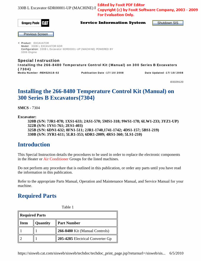
8. Close the valves for the heater hoses in the engine compartment.
Removing the Storage Box and the Covers (Cab)
Note: The components in your machine may not appear to be identical with the components in the following photographs. The photographs should be referenced as typical configurations.
1. Place the operator's seat in the full forward position.
2. Remove four screws (1) .
Illustration 2 g01053990
Example
Illustration 3 g00573876
Page 4 of 25330B L Excavator 6DR00001-UP (MACHINE) POWERED BY 3306 Engine(SEBP2437...
6/5/2010https://sisweb.cat.com/sisweb/sisweb/techdoc/techdoc_print_page.jsp?returnurl=/sisweb/sis...
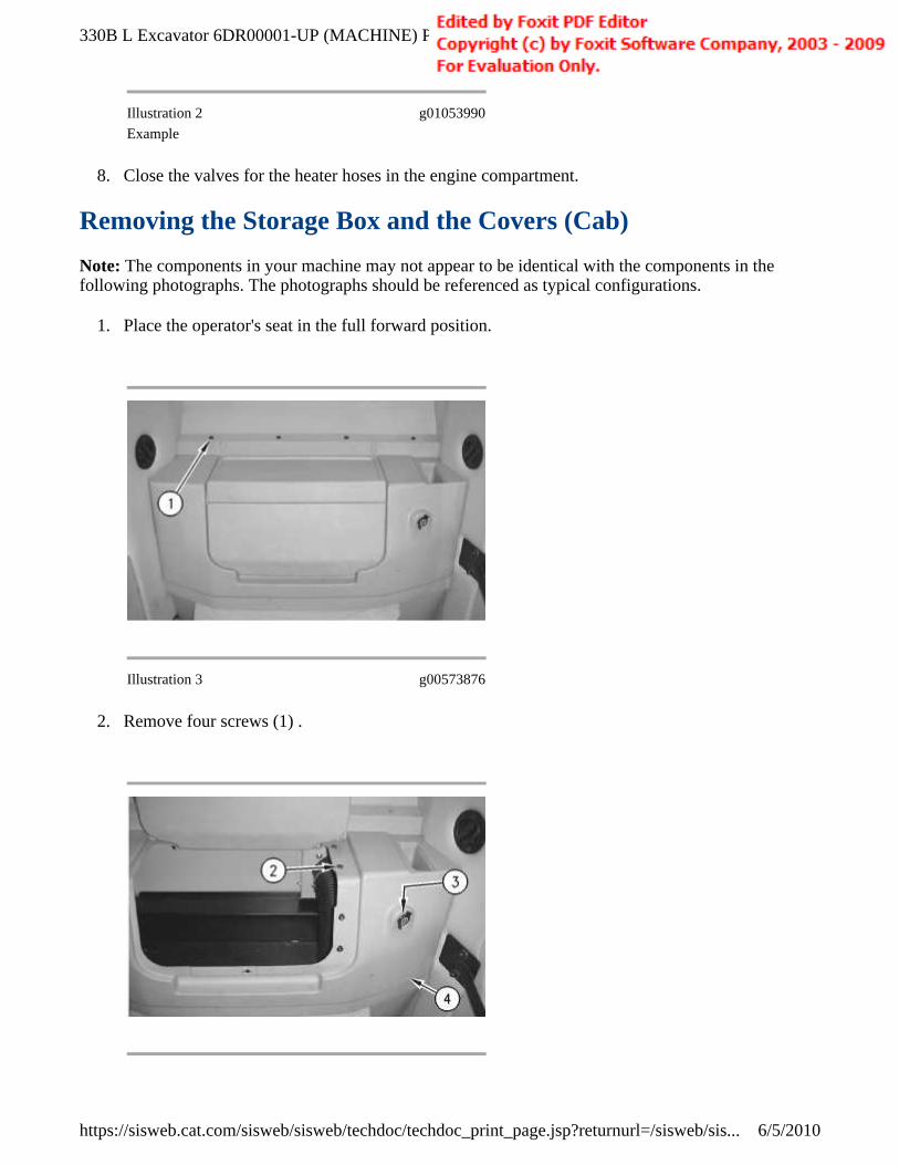
3. Open the storage box. Disconnect two wires from 12 V socket (3), if the socket exists. Remove four screws (2). Remove cover (4) .
4. Remove two screws (5). Remove screen (6) and the filter.
5. Remove two screws (7) and the plates. Remove cover (8) .
Illustration 4 g00573879
Illustration 5 g00577139
Illustration 6 g00577143
Page 5 of 25330B L Excavator 6DR00001-UP (MACHINE) POWERED BY 3306 Engine(SEBP2437...
6/5/2010https://sisweb.cat.com/sisweb/sisweb/techdoc/techdoc_print_page.jsp?returnurl=/sisweb/sis...
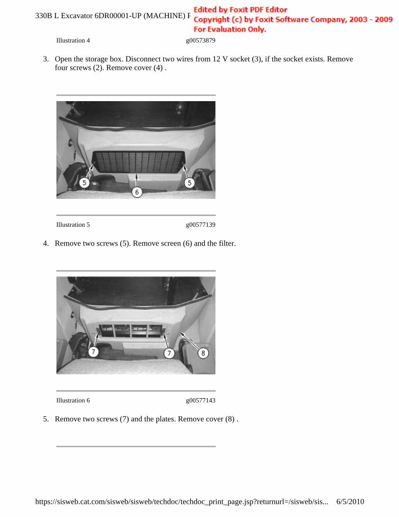
6. Remove bolt (11) and the washer. Disconnect relay (15). Remove relay (15). Remove grommet (16). Feed wire harness (12) through the box assembly. Feed wire harness (18) through the box assembly.
7. Loosen two clamps (10). Remove fresh air duct (13). Remove two bolts (17), the nuts, and the washers. Remove bracket (14). Remove four bolts (9) and the washers.
8. Reposition box assembly (19) in order to access hose clamp (20). Loosen hose clamp (20). Remove hose (21). Remove box assembly (19) .
Illustration 7 g00574475
Illustration 8 g00574479
Page 6 of 25330B L Excavator 6DR00001-UP (MACHINE) POWERED BY 3306 Engine(SEBP2437...
6/5/2010https://sisweb.cat.com/sisweb/sisweb/techdoc/techdoc_print_page.jsp?returnurl=/sisweb/sis...

9. Remove two bolts (22) and the washers. Remove two bolts (23), the washers, and the spacers.
10. Remove plate (24). The weight of plate (24) is approximately 7 kg (15 lb.)
Note: Mark the location of the wire tie-wraps when the wraps are removed. The mark will simplify reassembly.
11. Remove the wire tie wraps. Disconnect electrical connector (25). The connector is attached to the ambient air temperature sensor. Pull the wire harness through the operator platform.
Removing The Components from the 128-9726 Cab Heater Gp
Illustration 9 g00637584
Illustration 10 g00637727
Page 7 of 25330B L Excavator 6DR00001-UP (MACHINE) POWERED BY 3306 Engine(SEBP2437...
6/5/2010https://sisweb.cat.com/sisweb/sisweb/techdoc/techdoc_print_page.jsp?returnurl=/sisweb/sis...

1. Remove bolt (28) and the washer from upper air duct (27). Peel back two rubber gaskets (26) on each side of the upper air duct (27). Remove upper air duct (27) .
2. Disconnect the electrical connectors (29) to the fresh air actuator and upper body actuator mounted on the case assembly.
Illustration 11 g00638237
Illustration 12 g00638239
Page 8 of 25330B L Excavator 6DR00001-UP (MACHINE) POWERED BY 3306 Engine(SEBP2437...
6/5/2010https://sisweb.cat.com/sisweb/sisweb/techdoc/techdoc_print_page.jsp?returnurl=/sisweb/sis...

3. Remove four bolts (31) and the washers. Retain the bolts and washers for reassembly. Remove top case cover (30). Retain the top cover for reassembly.
Illustration 13 g00638267
Illustration 14 g01171432
The 128-9726 Cab Heater Gp showing parts to be removed.
Page 9 of 25330B L Excavator 6DR00001-UP (MACHINE) POWERED BY 3306 Engine(SEBP2437...
6/5/2010https://sisweb.cat.com/sisweb/sisweb/techdoc/techdoc_print_page.jsp?returnurl=/sisweb/sis...
4. Remove the parts shown in Illustration 14 and retain all mounting screws, bolts, and washers for later use during assembly.
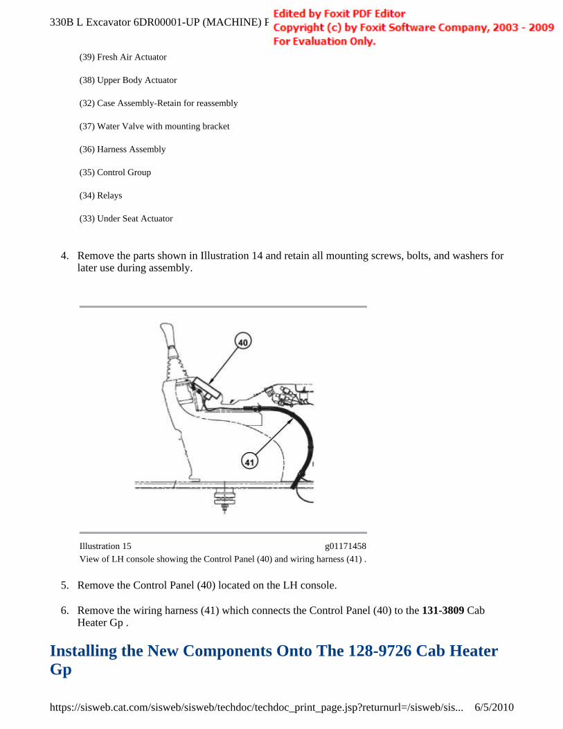
5. Remove the Control Panel (40) located on the LH console.
6. Remove the wiring harness (41) which connects the Control Panel (40) to the 131-3809 Cab Heater Gp .
Installing the New Components Onto The 128-9726 Cab Heater Gp
(39) Fresh Air Actuator
(38) Upper Body Actuator
(32) Case Assembly-Retain for reassembly
(37) Water Valve with mounting bracket
(36) Harness Assembly
(35) Control Group
(34) Relays
(33) Under Seat Actuator
Illustration 15 g01171458
View of LH console showing the Control Panel (40) and wiring harness (41) .
Page 10 of 25330B L Excavator 6DR00001-UP (MACHINE) POWERED BY 3306 Engine(SEBP24...
6/5/2010https://sisweb.cat.com/sisweb/sisweb/techdoc/techdoc_print_page.jsp?returnurl=/sisweb/sis...

Secure the 245-1596 Actuator with the screws and washers retained during disassembly.
1. Install a 245-1596 Actuator (43) to the Upper Body Door. The Upper Body door will be in the closed position when the 245-1596 Actuator is installed. Secure the Actuator with the screws and washers retained during disassembly. Install a 245-1596 Actuator (42) to the Fresh Air Door. The Fresh Air Door will be in the open position when the 245-1596 Actuator Actuator is installed.
Note: May need to rotate Fresh Air Door slightly closed to align Actuator mounting holes.
Illustration 16 g01171480
Installation of new Fresh Air Actuator and Upper Body Actuator onto the Case Assembly.
Page 11 of 25330B L Excavator 6DR00001-UP (MACHINE) POWERED BY 3306 Engine(SEBP24...
6/5/2010https://sisweb.cat.com/sisweb/sisweb/techdoc/techdoc_print_page.jsp?returnurl=/sisweb/sis...

2. Install a 245-1596 Actuator (44) to the Under Seat Door. The Under Seat Door will be in the closed position when the 245-1596 Actuator is installed. Secure the Actuator with the screws and washers retained during disassembly.
Note: May need to rotate Under Seat Door slightly open to align Actuator mounting holes.
Illustration 17 g01171503
Illustration 18 g01171635
Page 12 of 25330B L Excavator 6DR00001-UP (MACHINE) POWERED BY 3306 Engine(SEBP24...
6/5/2010https://sisweb.cat.com/sisweb/sisweb/techdoc/techdoc_print_page.jsp?returnurl=/sisweb/sis...