I SOFT -CORE NIOS II P ROCESSOR FOR VGA A...
15
Abstract Today’s embedded system designing industries use FPGAs for rapid prototyping, a demand of industry for de- velopment of precision and fast processing speeds with short turnaround times across a variety of applications. Board-level prototyping methods are described as a signifi- cant piece of the embedded system design flow. In addition, simulation, debug and reconfiguration prototyping tools provide functional and performance verification. This study used an Altera DE2 board as a platform to implement a game called air hockey (single slider) or pong game. The Quartus II 7.0 and Nios II 7.0 eclipse are used as software design tools. The Altera DE2 boards, which contain Cy- clone II 2C35 FPGAs, were used as hardware to communi- cate with the peripherals, i.e. VGA and USB. Introduction Engineering educational games and competitions— including events such as robotic events, egg drops, pumpkin launches and paper airplane design—help to educate stu- dents in the design of projects. Educational games have rap- idly become popular. Many domestic and international ex- periences show that educational games have a significant influence on the growth of young people [1-4]. In electrical and computer engineering conferences and workshops, stu- dent competitions such as programming and robotics tend to dominate the landscape in the form of robot soccer and au- tonomous vehicle navigation. These challenge engineering students to reach a higher level of skill and knowledge. By configuring hardware with the soft-core Nios II CPU de- signed on the DE2 Board, the authors were able to create the sought-after game environment. Through the use of the system, one can immediately see that it is highly responsive to the user’s hand movements, and the dynamics of the game emulate real experience exceptionally well. Applications The user interactive virtual environment has a wide range of applications due to the advantage that the user’s physical movements have interactions with the graphical world. It may be for fun, learning, exploring or making selections in order to find their key role. This makes virtual environments useful in gaming, pilot training for using aircraft simulators, car driving, as well as selection of options on ATMs, cash registers, and industrial automation for setting the parame- ters for the equipment. The Graphic User Interface (GUI) has a wide range of applications and its areas are increasing due to the involvement of high-performance electronic hard- ware coming onto the market on a daily basis. The best ex- ample can be seen in surgical robotics, endoscopy and deep- water ocean research. These applications require fast and precise user hand movements to be transferred to the ma- chine’s robotic movements. Soft-Core Processor A soft processor is a microprocessor core that can be cus- tomized and implemented logic descriptions that can be included with the rest of the design, compiled into a gate- level description, and routed onto the FPGA. Typically, a soft processor is described in Verilog or VHDL and then combined with the remainder of the Verilog or VHDL de- sign [5]. The soft processor typically made of logical ele- ments found in FPGAs and described in a Hardware De- scription Language (HDL), like VHDL or Verilog. The common soft-core include Nios, Nios II, Pico Blaze, Micro Blaze, Lattice Mic08 and so on, among which the Nios II develop by Altera Corp. and the Micro Blaze developed by Xilinx Corp [6]. In a soft-core processor, the designer has the flexibility to choose the instruction set, hardware fea- tures, and the data and address size as shown in Figure 1. Hardcore processors have a fixed instruction set and archi- tecture, and can be designed for a specific purpose. Figure 1. FPGA-Based Soft Core ——————————————————————————————————————————————–———— Saeid Moslehpour, University of Hartford; Kouroush Jenab, Society of Reliability Engineering-Ottawa; Balvinder Singh Pabla, University of Hartford IMPLEMENTING A SOFT-CORE NIOS II PROCESSOR FOR VGA APPLICATIONS ——————————————————————————————————————————————–———— 12 INTERNATIONAL JOURNAL OF ENGINEERING RESEARCH AND INNOVATION | V4, N2, FALL/WINTER 2012
Transcript of I SOFT -CORE NIOS II P ROCESSOR FOR VGA A...

Abstract
Today’s embedded system designing industries use
FPGAs for rapid prototyping, a demand of industry for de-
velopment of precision and fast processing speeds with
short turnaround times across a variety of applications.
Board-level prototyping methods are described as a signifi-
cant piece of the embedded system design flow. In addition,
simulation, debug and reconfiguration prototyping tools
provide functional and performance verification. This study
used an Altera DE2 board as a platform to implement a
game called air hockey (single slider) or pong game. The
Quartus II 7.0 and Nios II 7.0 eclipse are used as software
design tools. The Altera DE2 boards, which contain Cy-
clone II 2C35 FPGAs, were used as hardware to communi-
cate with the peripherals, i.e. VGA and USB.
Introduction
Engineering educational games and competitions—
including events such as robotic events, egg drops, pumpkin
launches and paper airplane design—help to educate stu-
dents in the design of projects. Educational games have rap-
idly become popular. Many domestic and international ex-
periences show that educational games have a significant
influence on the growth of young people [1-4]. In electrical
and computer engineering conferences and workshops, stu-
dent competitions such as programming and robotics tend to
dominate the landscape in the form of robot soccer and au-
tonomous vehicle navigation. These challenge engineering
students to reach a higher level of skill and knowledge. By
configuring hardware with the soft-core Nios II CPU de-
signed on the DE2 Board, the authors were able to create
the sought-after game environment. Through the use of the
system, one can immediately see that it is highly responsive
to the user’s hand movements, and the dynamics of the
game emulate real experience exceptionally well.
Applications
The user interactive virtual environment has a wide range
of applications due to the advantage that the user’s physical
movements have interactions with the graphical world. It
may be for fun, learning, exploring or making selections in
order to find their key role. This makes virtual environments
useful in gaming, pilot training for using aircraft simulators,
car driving, as well as selection of options on ATMs, cash
registers, and industrial automation for setting the parame-
ters for the equipment. The Graphic User Interface (GUI)
has a wide range of applications and its areas are increasing
due to the involvement of high-performance electronic hard-
ware coming onto the market on a daily basis. The best ex-
ample can be seen in surgical robotics, endoscopy and deep-
water ocean research. These applications require fast and
precise user hand movements to be transferred to the ma-
chine’s robotic movements.
Soft-Core Processor
A soft processor is a microprocessor core that can be cus-
tomized and implemented logic descriptions that can be
included with the rest of the design, compiled into a gate-
level description, and routed onto the FPGA. Typically, a
soft processor is described in Verilog or VHDL and then
combined with the remainder of the Verilog or VHDL de-
sign [5]. The soft processor typically made of logical ele-
ments found in FPGAs and described in a Hardware De-
scription Language (HDL), like VHDL or Verilog. The
common soft-core include Nios, Nios II, Pico Blaze, Micro
Blaze, Lattice Mic08 and so on, among which the Nios II
develop by Altera Corp. and the Micro Blaze developed by
Xilinx Corp [6]. In a soft-core processor, the designer has
the flexibility to choose the instruction set, hardware fea-
tures, and the data and address size as shown in Figure 1.
Hardcore processors have a fixed instruction set and archi-
tecture, and can be designed for a specific purpose.
Figure 1. FPGA-Based Soft Core
——————————————————————————————————————————————–———— Saeid Moslehpour, University of Hartford; Kouroush Jenab, Society of Reliability Engineering-Ottawa;
Balvinder Singh Pabla, University of Hartford
IMPLEMENTING A SOFT-CORE NIOS II PROCESSOR
FOR VGA APPLICATIONS
——————————————————————————————————————————————–————
12 INTERNATIONAL JOURNAL OF ENGINEERING RESEARCH AND INNOVATION | V4, N2, FALL/WINTER 2012

——————————————————————————————————————————————–————
Nios II
This 32-bit soft-core processor architecture was devel-
oped by Altera Corporation. The older Nios was introduced
in 2001 and was industry’s first viable commercial proces-
sor created specifically for embedded system design in
FPGAs. Nios II was embedded directly into FPGAs, which
allowed for performance of more than 200DMIPS, and us-
ers could select more than 60 IP cores [7]. It also allows
designers to include the available IP (Intellectual Property)
modules during the design phase, which saves a lot of time
[8].
The soft-core nature of the Nios II processors let design-
ers integrate custom logic into the arithmetic logic unit
(ALU) (Figure 2). The Avalon Switch Fabric (ASF) is one
of the key features that differentiate the cyclone FPGA from
other vendors’ FPGA products. ASF is a high-bandwidth
interconnect structure that offers greater flexibility than a
shared bus. The switched interconnect structure of the ASF
connects the master and slave ports. Nios II implements the
function of the control and interpolation algorithm and the
communication between the computer and the FPGA.
Figure 2. Nios II Soft-Core Processor
A master can connect to multiple slaves, and a slave can
be connected to multiple masters. When a slave is driven by
multiple masters, arbitration logic is automatically generat-
ed by Altera’s System on a Programmable Chip (SoPC)
Builder. Arbitration, by default, utilizes a round-robin mas-
ter selection, but priorities can be associated with masters
and used for selection. The DMA controller is given access
to the data memory as well as the CPU. This allows data
retrieval to take place without relaying the instruction
through the system CPU. An interesting point is that the
DMA controller accesses the VGA controller. The ad-
vantage of the Nios II processors is that they contain soft-
core processors and there are numerous tools available for
them. The hardware-assisted debug module is especially
useful for tracing applications. Ware-development environ-
ment easily allows the user to rapidly implement a proto-
type. For obtaining higher performance, the Nios II fast
CPU core can be chosen. It contains a single-cycle hardware
multiplier and dynamic branch prediction features that in-
crease the performance of the application. Dynamic branch
prediction means to perform pre-fetching of sequential in-
structions in order to keep the pipeline as active as possible.
Multipliers usually require more than one clock cycle, but
with the single-cycle hardware multiplier, some highly
mathematical applications can benefit from the optimization
feature. The brief overview of the DE2 board displays the
usefulness of the development board for rapid prototyping
for a range of applications.
Equipment and Software Package
DE2 Board
On a Cyclone II EP2C35 FPGA chip, all important com-
ponents on the board are connected to the pins of this chip
to allow the user to configure the connection between the
various components as desired (Figure 3).
Figure 3. Region of the DE2 Board
Altera’s DE2 board has become one of the most widely
used FPGA boards for the development of FPGA designs
(Figure 4) [8-10].
Programming the DE2 Board
The Cyclone II FPGA can be programmed by way of the
JTAG programming method or the EPCS16 Configuration
Device programming method.
——————————————————————————————————————————————–————
IMPLEMENTING A SOFT-CORE NIOS II PROCESSOR FOR VGA APPLICATIONS 13
——————————————————————————————————————————————–————
14 INTERNATIONAL JOURNAL OF ENGINEERING RESEARCH AND INNOVATION | V4, N2, FALL/WINTER 2012
——————————————————————————————————————————————–————
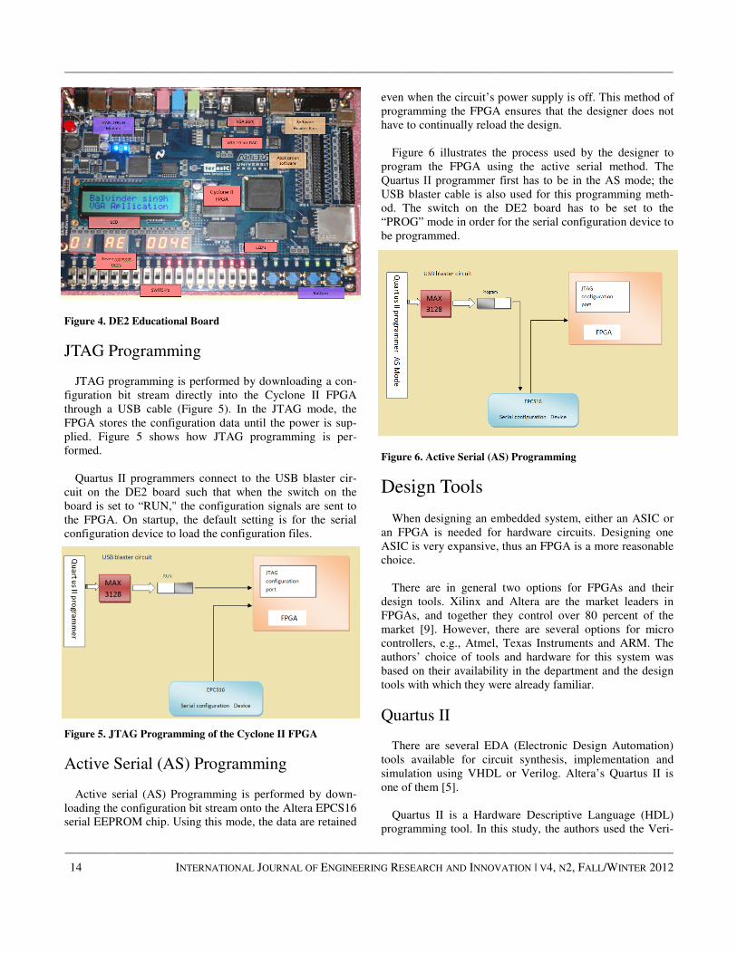
Figure 4. DE2 Educational Board
JTAG Programming
JTAG programming is performed by downloading a con-
figuration bit stream directly into the Cyclone II FPGA
through a USB cable (Figure 5). In the JTAG mode, the
FPGA stores the configuration data until the power is sup-
plied. Figure 5 shows how JTAG programming is per-
formed.
Quartus II programmers connect to the USB blaster cir-
cuit on the DE2 board such that when the switch on the
board is set to “RUN," the configuration signals are sent to
the FPGA. On startup, the default setting is for the serial
configuration device to load the configuration files.
Figure 5. JTAG Programming of the Cyclone II FPGA
Active Serial (AS) Programming
Active serial (AS) Programming is performed by down-
loading the configuration bit stream onto the Altera EPCS16
serial EEPROM chip. Using this mode, the data are retained
even when the circuit’s power supply is off. This method of
programming the FPGA ensures that the designer does not
have to continually reload the design.
Figure 6 illustrates the process used by the designer to
program the FPGA using the active serial method. The
Quartus II programmer first has to be in the AS mode; the
USB blaster cable is also used for this programming meth-
od. The switch on the DE2 board has to be set to the
“PROG” mode in order for the serial configuration device to
be programmed.
Figure 6. Active Serial (AS) Programming
Design Tools
When designing an embedded system, either an ASIC or
an FPGA is needed for hardware circuits. Designing one
ASIC is very expansive, thus an FPGA is a more reasonable
choice.
There are in general two options for FPGAs and their
design tools. Xilinx and Altera are the market leaders in
FPGAs, and together they control over 80 percent of the
market [9]. However, there are several options for micro
controllers, e.g., Atmel, Texas Instruments and ARM. The
authors’ choice of tools and hardware for this system was
based on their availability in the department and the design
tools with which they were already familiar.
Quartus II
There are several EDA (Electronic Design Automation)
tools available for circuit synthesis, implementation and
simulation using VHDL or Verilog. Altera’s Quartus II is
one of them [5].
Quartus II is a Hardware Descriptive Language (HDL)
programming tool. In this study, the authors used the Veri-

——————————————————————————————————————————————–————
log language for describing the pin connections as they were
selected. The following IC hardware pins on the DE2 board
are mentioned here to indicate each input/output function
and operating mode: ADV 7123, ISP 1362, EP2C35, LCD
module, 7-Segment LED module, Red- Green LED’s (see
also Figures 7-9).
SoPC builder
SoPC is a new concept and approach proposed by Altera
Corporation [11]. It has features like combined programma-
ble logic elements EDA, SOC, DSP and IP, which help in
flexible design, ability to tailor the application, extension,
upgradability and programmable software and hardware for
system development. SoPC technology is an evolving syn-
thetic electronic designing technology [12]. The designing
technology of SoPC is the product of modern computer-
aided design technology, the EDA technology and the enor-
mous development of large-scale integrated-circuit technol-
ogy (Figure 10).
Figure 7. Quartus II Design Flow
Figure 8. Quartus II
——————————————————————————————————————————————–————
IMPLEMENTING A SOFT-CORE NIOS II PROCESSOR FOR VGA APPLICATIONS 15

——————————————————————————————————————————————–————
16 INTERNATIONAL JOURNAL OF ENGINEERING RESEARCH AND INNOVATION | V4, N2, FALL/WINTER 2012
——————————————————————————————————————————————–————
Figure 9. Quartus II Building Blocks
As show in Figure 11, it not only helps to select the hard-
ware but also helps the designer to enrich it with required
headers and supporting software. When SoPC Builder gen-
erates the hardware related to the core of the Nios II, it auto-
matically generates a software development kit, including
the peripheral device driver program, associated header files
and software libraries. In the process of the design, it can
call the software development kit in the header files and
library files to easily complete the software design [13].
SoPC platforms are becoming more prevalent as a solu-
tion for the implementation of embedded computing sys-
tems [12]. This is due to their ease of implementation and
highly customizable nature. It allows implementation of
conceptual designs to practically target platforms. For many
companies, mitigating the decision complexity at the con-
ceptual design stage can result in succeeding on the compet-
Figure 10. SoPC Design Environments
——————————————————————————————————————————————–————
itive market. Therefore, having a robust decision-making
tool embedded with conflict resolution for valuing potential
new product investments helps to justify their development
strategy [14]. It demonstrates a simple yet effective tech-
nique for accelerating an embedded RTOS running on a soft
-core CPU on a SoPC platform.
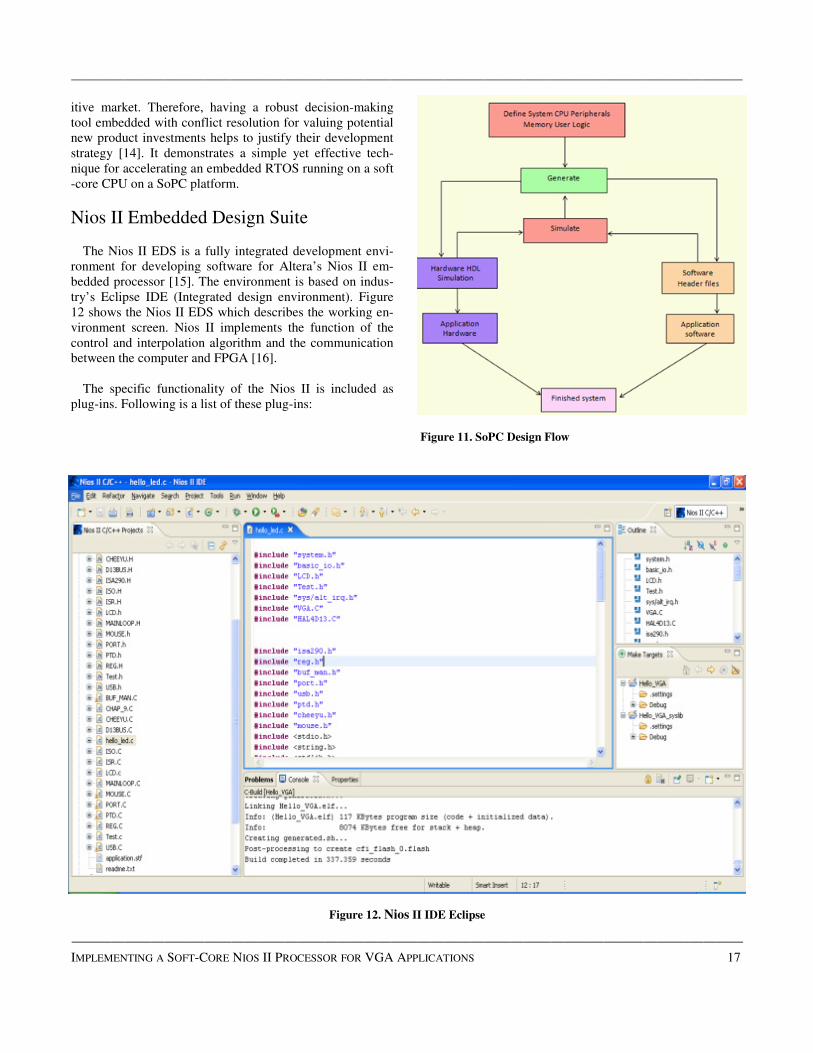
Nios II Embedded Design Suite
The Nios II EDS is a fully integrated development envi-
ronment for developing software for Altera’s Nios II em-
bedded processor [15]. The environment is based on indus-
try’s Eclipse IDE (Integrated design environment). Figure
12 shows the Nios II EDS which describes the working en-
vironment screen. Nios II implements the function of the
control and interpolation algorithm and the communication
between the computer and FPGA [16].
The specific functionality of the Nios II is included as
plug-ins. Following is a list of these plug-ins:
Figure 11. SoPC Design Flow
Figure 12. Nios II IDE Eclipse
——————————————————————————————————————————————–————
IMPLEMENTING A SOFT-CORE NIOS II PROCESSOR FOR VGA APPLICATIONS 17

——————————————————————————————————————————————–————
18 INTERNATIONAL JOURNAL OF ENGINEERING RESEARCH AND INNOVATION | V4, N2, FALL/WINTER 2012
——————————————————————————————————————————————–————
• Nios II Project managers
• Nios II Software Templates
• Nios II Flash Programmer
• Nios II BSP Editor
• Quartus II Programmer
• Nios II Command Shell
The Nios II EDS provides two distinct development flows
and includes many proprietary and open-source tools for
creating Nios II programs. This platform is suitable for the
software implementation of entire projects, since all devel-
opment, debug and state diagrams can be done in a single
window [15]. Eclipse IDE also provides different software
templates or display messages and functions as a terminal
when running code on a Nios II processor. The terminal will
display any message printed using C library functions like
print (). Print () is mainly used for transmitting data to the
output devices such as an LCD, as was the case for this
study. Quartus II helps programmers to program and imple-
ment code on FPGA chips. Software tools available with the
Altera DE2 board include:
• FPGA logic design
• The SoPC Builder is used for customization
• Nios II IDE Eclipse uses C/C++ coding of the pro-
cessor
In the Nios II IDE development flow, a Nios II C/C++
application project consists of a collection of source codes
plus a make file. A typical characteristic of an application is
that one of the source files contains the function main.o. An
application includes code that calls functions in libraries and
BSPs. The make file compiles the source code and links it
with a BSP and one or more optional libraries to create
one .elf file [17].
This design tool shortens the design processes, simplifies
the circuits and increases data reliability. Simulation and
testing results show that the data received are accurate,
which confirms the validity of the design [15].
Software Design
The software code is written in C language in the Nios II
IDE environment. This study built on the 'DE2_
NIOS_HOST_MOUSE_VGA' demonstration found in Al-
tera’s DE2 development board and educational CD. The
main function in the software controlling the Nios II proces-
sor is in the hello_VGA.c file. All of the .H header files
and .C code files are in the software folder. The main file
holds the majority of the code relevant to the game and
there is another file that controls all of the functions of the
mouse in the mouse.c file. This file and the included .h files
have the USB mouse connected and activated.
A function in the PTD.c or 'send_int' file is called to con-
tinuously poll. It monitors mouse activities for any move-
ment or clicking. Within this function there are other func-
tions like 'move_ball’, which makes the ball bounce and
other graphic activities. As the mouse is clicked or moved,
the 'send_int' function breaks out of a while loop and calls
the 'play_mouse' function. This function contains other
functions for the lines and ball collision detection, location
of the slider, ball erasing the sticks, etc. Also present in
the .C files are the following codes and explanations (see
Figures 13-16):
LCD.c
Hello_led.c
Mouse.c
Ptd.c
Figure 13. Flowchart of LCD.c

——————————————————————————————————————————————–————
Figure 14. Flowchart of Mouse.c
Figure 15. Flowchart of Hello_Led.c
Figure 16. Flowchart of Ptd.c
Setup
The Nios II soft-core processor is loaded with the soft-
ware written in C++ language. The configuration bit streams
from the computer (running Nios II IDE Eclipse) and is
used to flash. This software configures the FPGA (Altera
Cyclone II) as a CPU. The peripheral connected as an input
is a USB-driven mouse via chip ISP1362. The output dis-
play device is a VGA Monitor screen via chip ADV7123.
This on-board VGA controller chip (ADV7123) generates
the VGA picture with a resolution of 640x480. The frame
refresh rate is 60Hz.
The cursor movement of the USB mouse controls the left
and right movement of the slider; this movement is indicat-
ed via a series of red and green LEDs on the DE2 board. A
right click of the mouse starts ball bouncing. The screen
location or (x, y) coordinates of the bouncing ball location is
sent via software to the Nios II Eclipse. Also on the DE2
board, a 7-segment LED display indicates the x, y position
within the 640x480 screen frame (see Figure 17).
Challenges faced during this study were related to
memory and CPU usage of the program. During flashing of
the program code on Altera’s Nios IDE, it took a lot of time
to transfer the configuration of the bit stream.
——————————————————————————————————————————————–————
IMPLEMENTING A SOFT-CORE NIOS II PROCESSOR FOR VGA APPLICATIONS 19

——————————————————————————————————————————————–————
20 INTERNATIONAL JOURNAL OF ENGINEERING RESEARCH AND INNOVATION | V4, N2, FALL/WINTER 2012
——————————————————————————————————————————————–————
Figure 17. Project Setup
Methodology for Formation of
Structure
Structure gets displayed on a screen by the pixel arrange-
ments. The address is nothing but the coordinates of a pixel
indicating the location. The original image is represented on
the screen with the arrangements of these dots or pixels (see
Figures 18 and 19).
Figure 18. Magnifications of the Display Showing Color Pixels
Figure 19. Letter R in a Bracket Formed of the Off Pixel
All the objects are formed by pixel arrangement in order.
The line is simply a row of pixels set in the x-axis direction.
Thus, the code has to set pixels in the x-coordinates leaving
y coordinates constant (see Figure 20).
Figure 20. Formation of Lines by Pixel Arrangements
Thus, code can set or clear a row of pixels. This can be
done by a variable inside a for loop which increments up to
the entire length of the x-axis (Figure 21).
Figure 21. Code for Formation of a Line
A rectangle can be formed by the collection of all the
lines. First, a line is formed which is only one pixel of the y-
axis. Then, a cursor increments its position in the direction
and again a row of a line is formed. Formation of a group of
lines together leads to the formation of the structure of a
rectangle (see Figures 22-24).
Figure 22. Geometry of a Rectangle
Figure 23. Formation of a Rectangle
Figure 24. Code for Formation of a Rectangle
Pixels
Off pixels
void drawLine(int l1x,int l2x)
{
int lx=0,
lx = l1x;
for(x_Index=l1x;x_Index<=l2x;x_Index++)
{
void drawRectangleF(int rX1,int rX2)
{
int lx=0,ly=0;
lx = rX1;
ly = 450;
for(y_Index=0;y_Index<=8;y_Index++)

——————————————————————————————————————————————–————
A ball is nothing but a circle filled with solid color and
which has a constant radius circulating around a fixed point.
A circle is a simple shape of a point’s equidistance from a
center (see Figure 25).
Figure 25. Circle
On the screen, a circle can be drawn with the help of a
pixel arrangement. In the beginning, the code will start in-
creasing the pixel number on the x-axis until the line of a
certain diameter is reached. Thereafter, it starts to decrease
the number of pixels until a single pixel is achieved, as
shown in Figures 26 and 27. For simplicity, the authors only
used a square of 5x5 pixels.
Figure 26. Circle Formed of Pixel Dots
Figure 27. C Code for the Formation of the Ball
Initial Screen
In the initial stage, the ball is sitting in the middle of the
slider which is 50 pixels in length and 5 pixels in width. So
the x-coordinate of the slider will be half of that or 25. In
this situation, the code is going to set the pixel at the ball
X=ballposX+25 (see Figure 28).
Figure 28. Initial Screen Before User Presses Left Click
This will draw a ball after 25 pixels correspond to what-
ever current cursor location is updated from the mouse poll-
ing function. In the initial stage, the code continues to moni-
tor whether the user has clicked the left mouse button; e.g.,
get B = 1. If the left mouse button is pressed, the start flag
becomes set: start Flag = 1. At this point, the ball bounces
or the ball is in motion.
If (B==1).
{
start Flag = 1; //because until clicking, ball
should be stacked with the stick
ballX=ballposX+25;
ballY=445;
}
Once the left mouse button is pressed, the ball starts mov-
ing towards the upper right then it hits the wall and changes
the direction to the upper left. Thereafter, the ball touches
the first line it encounters and erases it.
Upward Motion
This code uses the directional vector diry. “If diry==1”
means that the ball is going up. The code will run for two
loops of y_index and x_index. First, in order to make an
object move, the screen has to clear its previous image and
set the pixel for the current one. For example, assume the
extern void drawBall(int bX,int bY)
// this function will draw a ball (square) of the center (bx , by)
{
int lx=0,ly=0;
lx = bX;
ly = bY;
for(y_Index=bY;y_Index<=(bY+5);y_Index++)
//height of the ball is 5 pixel
{
——————————————————————————————————————————————–————
IMPLEMENTING A SOFT-CORE NIOS II PROCESSOR FOR VGA APPLICATIONS 21

——————————————————————————————————————————————–————
22 INTERNATIONAL JOURNAL OF ENGINEERING RESEARCH AND INNOVATION | V4, N2, FALL/WINTER 2012
——————————————————————————————————————————————–————
ball has just left the slider and is moving towards the wall
(see Figures 29 and 30).
Figure 29. Motion of the Ball Moving Upward
Figure 30. C Code Ball in Motion Upward
In order to create a future state code, it has to clear at x+5,
y-5 as the x-coordinate of the ball increases and the y-
coordinate of the ball decreases. Code will draw (set) the
ball for x+5, y+5 coordinates. Once the ball hits the wall, it
moves up and to the left. In that case, the x- and y-
coordinates decrease. This process is repeated but now the
code will clear the pixels at x-5, y+5 and set x+5, y+5.
Downward Motion
As depicted in Figures 31 and 32, if the ball is moving in
the downward direction, there will be a decrease in the y-
coordinate. There will also be an increase or decrease in the
x coordinate depending upon the location of the ball.
• If it has not yet hit the wall, there will be a de-
crease in the x-coordinate.
• After hitting the wall, there will be an increase in
the x-coordinate.
Figure 31. Downward Motion of the Ball and Pixel Formation
Let us assume the ball has just touched the top lines and it
has not yet hit wall. In that case, the code will clear the x-5,
y+5 pixels. After hitting the wall, the code will clear the
x+5, y+5 pixels.
When the ball moves in the open space, there is an in-
crease in the x-coordinate or y-coordinate depending upon
which quadrant it is in. The code uses the dirX and dirY
vectors which are set or cleared depending upon whether the
x-coordinate has increased or decreased.
if(dirX == 0 && dirY == 0)
{
ballX--;ballY--;
}
else if(dirX == 0 && dirY == 1)
{
ballX--;ballY++;
}
else if(dirX == 1 && dirY == 0)
{
ballX++;ballY--;
}

——————————————————————————————————————————————–————
else if(dirX == 1 && dirY == 1)
{
ballX++;ballY++;
}
Figure 32. C Code for the Downward Direction of the Ball
In this study, a video raster of 640x480 pixels was creat-
ed. Technically, one wall is at x=0 and another is at x=640.
From a software point of view, the code is checking via
directional vectors (see Figure 33).
Figure 33. Directions of the Ball Hitting Walls
The path and direction vectors are:
§ 1st path: x++ y—
§ 2nd path: x-- y--
§ 3rd path: x++ y++
§ 4th path: x-- y++
If the current ball position is 635, then it is near the right-
most wall (ballx<635) as our ball was 5 pixels wide. Or
ballx<1 for the first wall; if this condition is satisfied then
the code will make directional vector dirX change direction
(see Figure 34).
Figure 34. Ball Striking the Walls
if(ballX>635)
{
dirX = 0; // stop motion in x axis up
}
else if(ballX<1)
{
dirX = 1;
}
When the ball reaches the top, the code will clear the pix-
els for the entire length of the lines and make the ball
change its y-axis direction and proceed moving downwards
(see Figure 35).
dirY = 1;
if(Bottom_Line > 1)
Bottom_Line = Bottom_Line - 1;
else
Bottom_Line = 0;
if(ballX < 320)
{
for(y_Index=(Bottom_Blocks
[Bottom_Line]);y_Index<=(Bottom_Blocks
[Bottom_Line]+5);y_Index++)
{
for(x_Index=0;x_Index<=320;x_Index++)
{
Vga_Clr_Pixel(VGA_0_BASE,x_Index,y_Index);
}
}
}
——————————————————————————————————————————————–————
IMPLEMENTING A SOFT-CORE NIOS II PROCESSOR FOR VGA APPLICATIONS 23

——————————————————————————————————————————————–————
24 INTERNATIONAL JOURNAL OF ENGINEERING RESEARCH AND INNOVATION | V4, N2, FALL/WINTER 2012
——————————————————————————————————————————————–————
else
{
for(y_Index=(Bottom_Blocks
[Bottom_Line]);y_Index<=(Bottom_Blocks
[Bottom_Line]+5);y_Index++)
{
for(x_Index=320;x_Index<=640;x_Index++)
{
Vga_Clr_Pixel(VGA_0_BASE,x_Index,y_Index);
}
Figure 35. Erasing of the Top Lines
A loop check checks to see if the x-coordinate of the fall-
ing ball is equal to the x-coordinate of the slider (xàx+50).
If so, the direction of the falling ball is changed to up. If the
condition is not reached, this means that the ball will fall
down making the screen black; i.e., game over (see Figure
36).
Figure 36. Ball Touching the Slider
Results
In this study, text in the LCD.c file was added. The text
remains during the entire duration of code running on the
Nios II eclipse editor. Figure 37 presents the initial screen
showing the Altera DE2 and Terasic logo before pressing
the left mouse button so that the ball is sitting at the mid-
point of the slider.
Figure 37. Direction of the Mouse in the Leftmost Portion of
the Screen Indicated by Full Green LEDS
After pressing the left mouse button, the ball starts bounc-
ing and moves towards the walls as it continues moving
upward towards the sticks on top. As the ball advances, the
screen frame refreshes, erasing the background, thereby
making it dark blue, as shown in Figure 38.
Figure 38. Ball Going Up after Left Click is Pressed
After erasing the stick, the ball moves downward as it
makes its journey towards the slider, as shown in Figure 39.
If it moves further down and hits the slider, it will bounce
back upward, otherwise the game is over and the screen is
turned black.
The direction of movement of the mouse is indicated with
the red and green LEDs and location of the slider, as indi-
cated on the 7-segment LED display shown in Figure 40.
The authors were also successful in displaying the location

——————————————————————————————————————————————–————
of the ball (x-y coordinates) and the slider’s x-coordinate on
the console of the Nios II IDE, as shown in Figure 41.
Figure 39. Ball Coming Down After Erasing One Stick
Figure 40. Location of the Slider at the Leftmost Portion of the
Screen Indicated by a 7-Segment Display
Figure 41. Locations of the Ball and the Slider Indicated in the
Nios II IDE
Conclusion
The purpose of this study was to design a VGA-based
application using a Nios II as the core CPU. The authors
used USB, red/green LEDs and a 7-segment display, though
the device in this study had a primitive level of graphics and
no audio. This design tool shortens the design processes,
simplifies the circuits and increases data reliability. Simula-
tion and testing results showed that the data being received
were accurate, which verified the validity of the design.
Future work could include a software upgrade of animations
to increase the sharpness of the graphical objects.
Acknowledgements
The authors would like to express their sincere apprecia-
tion to the editor and anonymous referees for the comments
that enhanced the quality of this paper.
References
[1] Bi, T., & Song, T. (April, 2011). Problems and solu-
tions of educational game development. International
Conference on Consumer Electronics, Communica-
tions and Networks (CECNet). 3364-3367.
[2] Moslehpour, S., Jenab, K., & Valiveti, S. (2012).
GPS time reception using Altera SoPC builder and
Nios II: Application in train positioning. Internation-
al Journal of Industrial Engineering and Production
Research. 23(1), 13-21.
[3] Jenab, K., Khoury, S., & Sarfaraz, A. (2012). Fuzzy
complexity model for educational projects. Interna-
tional Journal of Industrial Engineering and Produc-
tion Research, 23(1), 1-5.
[4] Moslehpour, S., Jenab, K., & Namburi, N. (2011).
Smart RFID based design for inventory management
in health care. International Journal of Industrial
Engineering and Production Research, 22(4), 231-
236.
[5] Pedroni, V. (2004). Circuit Design with VHDL. Cam-
bridge, Massachusetts Institute of Technology, Mas-
sachusetts, USA.
[6] Wang, X. (June, 2011). Using FPGA-based configu-
rable processors in teaching hardware/software co-
design of embedded multiprocessor systems. IEEE
International Conference on Microelectronic Systems
Education (MSE). 114-117.
[7] Wang, W., & Zhong, G. 2010. The Design and Im-
plementation of High-Speed Data Acquisition Sys-
tem Based on Nios II. International Conference on
Computing, Control and Industrial Engineering
(CCIE). 334 - 336.
——————————————————————————————————————————————–————
IMPLEMENTING A SOFT-CORE NIOS II PROCESSOR FOR VGA APPLICATIONS 25

——————————————————————————————————————————————–————
26 INTERNATIONAL JOURNAL OF ENGINEERING RESEARCH AND INNOVATION | V4, N2, FALL/WINTER 2012
——————————————————————————————————————————————–————
[8] Obaid, Z. A., Sulaiman, A., & Hamidon, M. (July,
2009). FPGA-based Implementation of Digital Logic
Design using Altera DE2 Board. International Jour-
nal of Computer Science and Network Security, 9(8),
184-196.
[9] Adhikari, P., & Okaro, M. (August, 2011). Five-level
five-phase PWM signal generation using FPGA.
North American Power Symposium (NAPS). 1-5.
[10] Altera and Xilinx report, July 2008. Retrieved April,
2012, from http://seekingalpha.com/article/85478-
altera-and-xilinx-report-the-battle-continue.
[11] Wei, Z., & Jun, S. (September, 2011). A high-speed
serial data acquisition scheme based on Nios II. In-
ternational Conference on Electronics, Communica-
tions and Control (ICECC). 2417-2420.
[12] Ming, Z., & Ting, L. H. (April, 2011). The design of
the displaying system based on the SoPC embedded
chips. International Conference on Electric Infor-
mation and Control Engineering (ICEICE). 5477-
5480.
[13] Qisheng, Z., & Ming, D. (May, 2011). Design of
SoPC embedded development board based on
EP3C25. International Conference on E-Business
and E-Government (ICEE). 1-4.
[14] Jenab, K., Sarfaraz, A., & Ameli, M.T. (2012). A
conceptual design selection model considering con-
flict resolution. Journal of Engineering Design.
DOI:10.1080/09544828.2012.728203.
[15] Teoh, B. E., & Ragavan, S. V. (September, 2011).
PAINTbot - FPGA based wall painting service robot
prototype. IEEE Recent Advances in Intelligent Com-
putational Systems (RAICS). 777-782.
[16] Wu, A., Fu, Q., & Li, Y. (July, 2011). Development
of multi-axis stepper motion control system based on
Nios II. The Second International Conference on
Mechanic Automation and Control Engineering
(MACE). 1230-1232.
[17] Ye, X., & Huang, Z. (October, 2010). IFF Copy Pro-
tection Based on DS28E01 and Nios II processor.
International Symposium on Intelligence Information
Processing and Trusted Computing (IPTC). 516-519.
Biographies
SAEID MOSLEHPOUR is an Associate Professor and
Department Chair in the Electrical and Computer Engineer-
ing Department in the College of Engineering, Technology,
and Architecture at the University of Hartford. He holds
Ph.D. (1993) from Iowa State University and Bachelor of
Science (1989) and Master of Science (1990) degrees from
University of Central Missouri. His research interests in-
clude logic design, CPLDs, FPGAs, Embedded electronic
system testing and distance learning. Dr. Moslehpour can be
reached at [email protected].
KOUROUSH JENAB, Senior Member of IEEE, re-
ceived the B.Sc. degree from the IE Department at Isfahan
University of Technology (1989), the M.Sc. degree from the
IE Department at Tehran Polytechnic (1992), and the Ph.D.
degree from the Department of Mechanical Engineering at
the University of Ottawa (2005). He served as a senior engi-
neer/manager in auto, and high-tech industries for 18 years.
He joined National Research Council Canada as a research
officer where he participated in several international re-
search projects. In 2006, he joined the Department of Me-
chanical and Industrial Engineering at Ryerson University,
Toronto as assistant professor. Currently, Dr. Jenab is Edu-
cation Chair of Society of Reliability Engineering (SRE)-
Ottawa Chapter. He has published over 81 papers in interna-
tional scientific journals and conferences, edited a special
issue on Applied Computational Techniques in Engineering
and Technology for International Journal of Industrial Engi-
neering Computations, and had over 29 technical reports.
Dr. Jenab can be reached at [email protected].
BALVINDER SINGH PABLA received a Bachelor of
Engineering in Instrumentation and Controls from Gujarat
University in June 2007. He worked for nearly two years in
Nicolas Piramal and Amix Corporation as an executive en-
gineer. He received his Master’s degree in Electrical and
Computer Engineering at the University of Hartford in
2012.Balvinder Singh Pabla can be reached at