I. MODELS CFM56-7B20 CFM56-7B22 CFM56-7B24E00056EN 4 of 26 II. MODELS (CONT.) CFM56-7B26 CFM56-7B27...
26
* PAGE 1 2 3 4 5 6 7 8 9 10 11 12 13 14 15 16 17 18 19 20 21 22 23 24 25 26 REV. 10 8 8 8 8 8 8 8 8 8 8 8 8 8 8 8 8 10 10 10 10 10 10 10 10 10 LEGEND: "- -" INDICATES "SAME AS PRECEDING MODEL" "---" NOT APPLICABLE NOTE: SIGNIFICANT CHANGES ARE BLACK-LINED IN THE LEFT MARGIN. U.S. DEPARTMENT OF TRANSPORTATION FEDERAL AVIATION ADMINISTRATION TYPE CERTIFICATE DATA SHEET E00056EN TCDS NUMBER E00056EN REVISION: 10* DATE: August 9, 2016 CFM INTERNATIONAL, S.A. MODELS: CFM56-7B20 CFM56-7B20/2 CFM56-7B20/3 CFM56-7B20E CFM56-7B22 CFM56-7B22/2 CFM56-7B22/B1 CFM56-7B22/3 CFM56-7B22/3B1 CFM56-7B22E CFM56-7B22E/B1 CFM56-7B24 CFM56-7B24/2 CFM56-7B24/B1 CFM56-7B24/3 CFM56-7B24/3B1 CFM56-7B24E CFM56-7B24E/B1 CFM56-7B26/3 CFM56-7B26 CFM56-7B26/2 CFM56-7B26/B1 CFM56-7B26/3B1 CFM56-7B26/3B2F CFM56-7B26/3F CFM56-7B26/B2 CFM56-7B26E CFM56-7B26E/B1 CFM56-7B26E/B2 CFM56-7B26E/B2F CFM56-7B26E/F CFM56-7B27 CFM56-7B27A CFM56-7B27AE CFM56-7B27/3 CFM56-7B27/3F CFM56-7B26/3B2 CFM56-7B27/B1 CFM56-7B27/B3 CFM56-7B27/2 CFM56-7B27/3B1 CFM56-7B27/3B3 CFM56-7B27A/3 CFM56-7B27E/B1 CFM56-7B27/3B1F CFM56-7B27E/B3 CFM56-7B27E CFM56-7B27E/F CFM56-7B27E/B1F Engines of models described herein conforming with this data sheet (which is part of Type Certificate Number E00056EN) and other approved data on file with the Federal Aviation Administration, meet the minimum standards for use in certificated aircraft in accordance with pertinent aircraft data sheets and applicable portions of the Federal Aviation Regulations, provided they are installed, operated, and maintained as prescribed by the approved manufacturer's manuals and other approved instructions. TYPE CERTIFICATE (TC) HOLDER: CFM International, S.A. 2 Boulevard du General Martial Valin 75015 Paris, France I. MODELS CFM56-7B20 CFM56-7B22 CFM56-7B24 TYPE High bypass turbofan; coaxial front fan/booster driven by multi-stage low pressure turbine, multi-stage compressor with one-stage high pressure turbine CFM56-7B series: single annular combustor CFM56-7B/2 series: double annular combustor CFM56-7B/3 series: improved emissions single annular combustor CFM56-7B/3F series: improved emissions single annular combustor and increased EGT CFM56-7BE and 7BE/F series: improved HPC diffuser, HPT and LPT performance RATINGS (See NOTE 4) Takeoff (5 min. see NOTE 13), sea level, static thrust, lb. Maximum continuous, sea level static thrust, lb. 20,600/ 9,163 daN 19,400/ 8,630 daN 22,700/ 10,097 daN 22,300/ 9,920 daN 24,200/ 10,765 daN 22,800/ 10,142 daN Flat rating AMBIENT TEMPERATURE Takeoff Maximum continuous 86 o F / 30 o C 77 o F / 25 o C - - - - - - - -
Transcript of I. MODELS CFM56-7B20 CFM56-7B22 CFM56-7B24E00056EN 4 of 26 II. MODELS (CONT.) CFM56-7B26 CFM56-7B27...

* PAGE 1 2 3 4 5 6 7 8 9 10 11 12 13 14 15 16 17 18 19 20 21 22 23 24 25 26
REV. 10 8 8 8 8 8 8 8 8 8 8 8 8 8 8 8 8 10 10 10 10 10 10 10 10 10
LEGEND: "- -" INDICATES "SAME AS PRECEDING MODEL"
"---" NOT APPLICABLE
NOTE: SIGNIFICANT CHANGES ARE BLACK-LINED IN THE LEFT MARGIN.
U.S. DEPARTMENT OF TRANSPORTATION
FEDERAL AVIATION ADMINISTRATION
TYPE CERTIFICATE DATA SHEET E00056EN
TCDS NUMBER E00056EN
REVISION: 10*
DATE: August 9, 2016
CFM INTERNATIONAL, S.A.
MODELS:
CFM56-7B20 CFM56-7B20/2 CFM56-7B20/3
CFM56-7B20E CFM56-7B22 CFM56-7B22/2
CFM56-7B22/B1 CFM56-7B22/3 CFM56-7B22/3B1
CFM56-7B22E CFM56-7B22E/B1 CFM56-7B24
CFM56-7B24/2 CFM56-7B24/B1 CFM56-7B24/3
CFM56-7B24/3B1 CFM56-7B24E CFM56-7B24E/B1
CFM56-7B26/3 CFM56-7B26 CFM56-7B26/2
CFM56-7B26/B1 CFM56-7B26/3B1 CFM56-7B26/3B2F
CFM56-7B26/3F CFM56-7B26/B2 CFM56-7B26E
CFM56-7B26E/B1 CFM56-7B26E/B2 CFM56-7B26E/B2F
CFM56-7B26E/F CFM56-7B27 CFM56-7B27A
CFM56-7B27AE CFM56-7B27/3 CFM56-7B27/3F
CFM56-7B26/3B2 CFM56-7B27/B1 CFM56-7B27/B3
CFM56-7B27/2 CFM56-7B27/3B1 CFM56-7B27/3B3
CFM56-7B27A/3 CFM56-7B27E/B1 CFM56-7B27/3B1F
CFM56-7B27E/B3 CFM56-7B27E CFM56-7B27E/F
CFM56-7B27E/B1F
Engines of models described herein conforming with this data sheet (which is part of Type Certificate Number E00056EN) and other approved data on file with the Federal Aviation Administration, meet the minimum standards for use in certificated aircraft
in accordance with pertinent aircraft data sheets and applicable portions of the Federal Aviation Regulations, provided they are
installed, operated, and maintained as prescribed by the approved manufacturer's manuals and other approved instructions.
TYPE CERTIFICATE (TC) HOLDER: CFM International, S.A.
2 Boulevard du General Martial Valin
75015 Paris, France
I. MODELS CFM56-7B20 CFM56-7B22 CFM56-7B24
TYPE High bypass turbofan; coaxial front fan/booster driven by multi-stage low pressure turbine,
multi-stage compressor with one-stage high pressure turbine
CFM56-7B series: single annular combustor
CFM56-7B/2 series: double annular combustor
CFM56-7B/3 series: improved emissions single annular combustor
CFM56-7B/3F series: improved emissions single annular combustor and increased EGT
CFM56-7BE and 7BE/F series: improved HPC diffuser, HPT and LPT performance
RATINGS (See NOTE 4)
Takeoff (5 min. see NOTE 13),
sea level, static thrust, lb.
Maximum continuous, sea
level static thrust, lb.
20,600/
9,163 daN
19,400/
8,630 daN
22,700/
10,097 daN
22,300/
9,920 daN
24,200/
10,765 daN
22,800/
10,142 daN
Flat rating AMBIENT TEMPERATURE
Takeoff
Maximum continuous
86oF / 30
oC
77oF / 25
oC
- -
- -
- -
- -

E00056EN 2 of 26
I. MODELS (CONT.) CFM56-7B20 CFM56-7B22 CFM56-7B24
FUEL SYSTEM See NOTE 7 for approved fuels.
Fuel pump / SNECMA part
number (P/N)
(Combined boost and single
element gear-type pump)
Hydromechanical unit / GE P/N
340-402-104
340-402-105
1853M56
- -
- -
- -
- -
- -
- -
Electronic control unit / GE P/N
- Hardware
- Software
Identification plugs /
SNECMA P/N
1851M50
1853M33
2042M67
2044M16
1853M78
2044M25
340-131-712
340-131-717
340-203-201
340-198-850
340-198-950
- -
- -
- -
- -
- -
- -
340-131-721
340-131-726
340-203-301
340-199-250
340-199-350
- -
- -
- -
- -
- -
- -
340-131-732
340-131-737
340-203-401
340-200-050
340-200-150
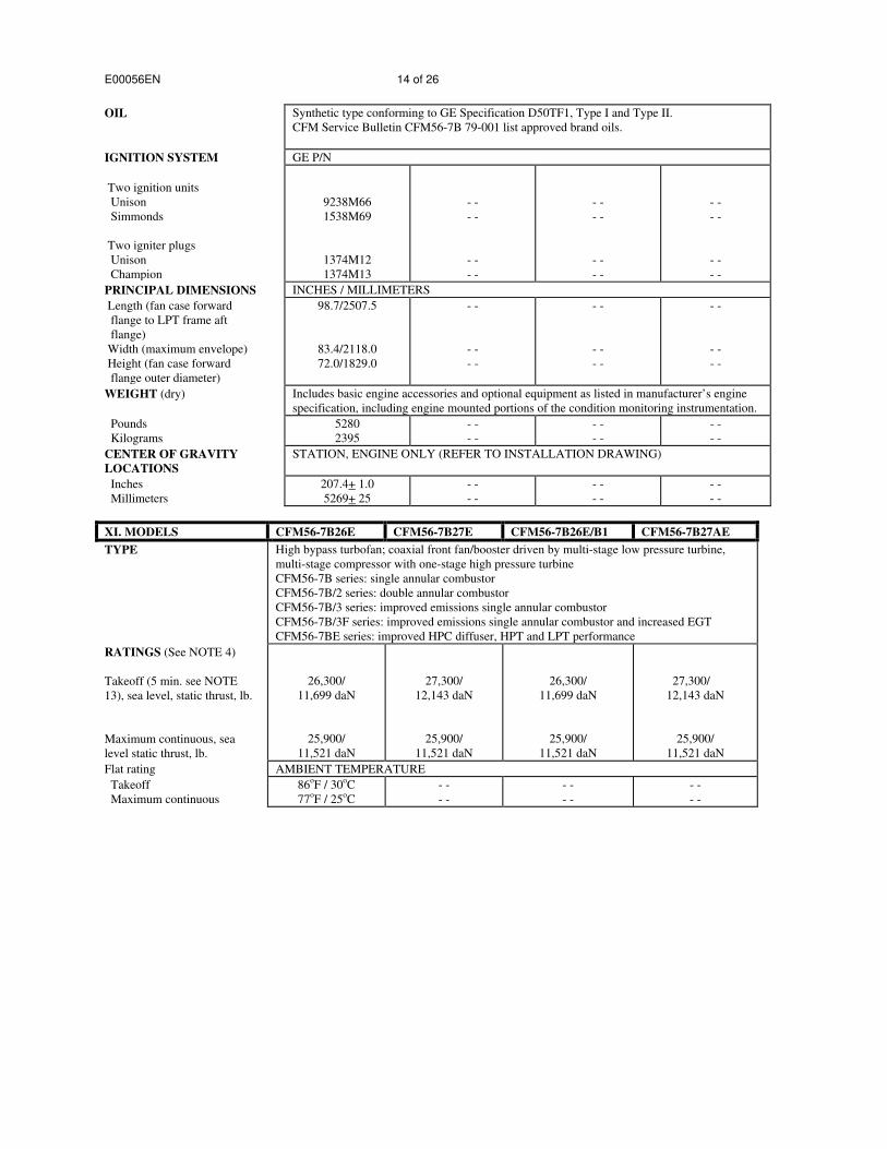
OIL Synthetic type conforming to GE Specification D50TF1, Type I and Type II.
CFM Service Bulletin CFM56-7B 79-001 list approved brand oils.
IGNITION SYSTEM GE P/N
Two ignition units
Unison
Simmonds
Two igniter plugs
Unison
Champion
9238M66
1538M69
1374M12
1374M13
- -
- -
- -
- -
- -
- -
- -
- -
PRINCIPAL DIMENSIONS INCHES / MILLIMETERS
Length (fan case forward
flange to LPT frame aft
flange)
Width (maximum envelope)
Height (fan case forward
flange outer diameter)
98.7/2507.5
83.4/2118.0
72.0/1829.0
- -
- -
- -
- -
- -
- -
WEIGHT (dry) Includes basic engine accessories and optional equipment as listed in manufacturer’s engine
specification, including engine mounted portions of the condition monitoring instrumentation.
Pounds
Kilograms
5260.0
2385.9
- -
- -
- -
- -
CENTER OF GRAVITY
LOCATIONS
STATION, ENGINE ONLY (REFER TO INSTALLATION DRAWING)
Inches
Millimeters
207.4+ 1.0
5269+ 25
- -
- -
- -
- -

E00056EN 3 of 26
II. MODELS CFM56-7B26 CFM56-7B27 CFM56-7B27A CFM56-7B20/2 CFM56-7B22/2
TYPE High bypass turbofan; coaxial front fan/booster driven by multi-stage low pressure turbine, multi-
stage compressor with one-stage high pressure turbine
CFM56-7B series: single annular combustor
CFM56-7B/2 series: double annular combustor
CFM56-7B/3 series: improved emissions single annular combustor
CFM56-7B/3F series: improved emissions single annular combustor and increased EGT
CFM56-7BE and 7BE/F series: improved HPC diffuser, HPT and LPT performance
RATINGS (See NOTE 4)
Takeoff (5 min. see NOTE
13), sea level, static thrust, lb.
Maximum continuous, sea
level static thrust, lb.
26,300/
11,699 daN
25,900/
11,521 daN
27,300/
12,143 daN
25,900/
11,521 daN
- -
- -
- -
- -
20,600/
9,163 daN
19,400/
8,630 daN
22,700/
10,097 daN
22,300/
9,920 daN
Flat rating AMBIENT TEMPERATURE
Takeoff
Maximum continuous
86oF / 30
oC
77oF / 25
oC
- -
- -
- -
- -
- -
- -
- -
- -
FUEL SYSTEM See NOTE 7 for approved fuels.
Fuel pump / SNECMA P/N
(Combined boost and single
element gear-type pump)
Hydromechanical unit /
GE P/N
340-402-104
340-402-105
1853M56
- -
- -
- -
- -
- -
- -
- -
- -
- -
- -
- -
- -
Electronic control unit /
GE P/N
- Hardware
- Software
Identification plugs /
SNECMA P/N
1851M50
1853M33
2042M67
2044M16
1853M78
2044M25
340-131-742
340-131-747
340-203-501
340-200-850
340-200-950
- -
- -
- -
- -
- -
- -
340-131-752
340-131-757
340-203-601
340-201-450
340-201-550
---
- -
- -
- -
- -
- -
340-203-701
---
---
---
---
1851M50
- -
- -
- -
- -
- -
340-138-710
340-138-715
340-203-201
---
---
- -
- -
- -
- -
- -
- -
340-138-720
340-138-725
340-203-301
---
---
OIL Synthetic type conforming to GE Specification D50TF1, Type I and Type II.
CFM Service Bulletin CFM56-7B 79-001 list approved brand oils.
IGNITION SYSTEM GE P/N
Two ignition units
Unison
Simmonds
Two igniter plugs
Unison
Champion
9238M66
1538M69
1374M12
1374M13
- -
- -
- -
- -
- -
- -
- -
- -
- -
- -
- -
- -
- -
- -
- -
- -
PRINCIPAL DIMENSIONS INCHES / MILLIMETERS
Length (fan case forward
flange to LPT frame aft
flange)
Width (maximum envelope)
Height (fan case forward
flange outer diameter)
98.7/2507.5
83.4/2118.0
72.0/1829.0
- -
- -
- -
- -
- -
- -
- -
- -
- -
- -
- -
- -

E00056EN 4 of 26
II. MODELS (CONT.) CFM56-7B26 CFM56-7B27 CFM56-7B27A CFM56-7B20/2 CFM56-7B22/2
WEIGHT (dry) Includes basic engine accessories and optional equipment as listed in manufacturer’s engine
specification, including engine mounted portions of the condition monitoring instrumentation.
Pounds
Kilograms
5260
2385.9
- -
- -
5282
2395.9
5360
2431.3
- -
- -
CENTER OF GRAVITY
LOCATIONS
STATION, ENGINE ONLY (REFER TO INSTALLATION DRAWING)
Inches
Millimeters
207.4 + 1.0
5269 + 25
- -
- -
- -
- -
- -
- -
- -
- -
III. MODELS CFM56-7B24/2 CFM56-7B26/2 CFM56-7B27/2 CFM56-7B26/B1
TYPE High bypass turbofan; coaxial front fan/booster driven by multi-stage low pressure turbine,
multi-stage compressor with one-stage high pressure turbine
CFM56-7B series: single annular combustor
CFM56-7B/2 series: double annular combustor
CFM56-7B/3 series: improved emissions single annular combustor
CFM56-7B/3F series: improved emissions single annular combustor and increased EGT
CFM56-7BE and 7BE/F series: improved HPC diffuser, HPT and LPT performance
RATINGS (See NOTE 4)
Takeoff (5 min. see NOTE 13),
sea level, static thrust, lb.
Maximum continuous, sea
level static thrust, lb.
24,200/
10,765 daN
22,800/
10,142 daN
26,300/
11,699 daN
25,900/
11,521 daN
27,300/
12,143 daN
25,900/
11,521 daN
26,300/
11,699 daN
25,900/
11,521 daN
Flat rating AMBIENT TEMPERATURE
Takeoff
Maximum continuous
86oF / 30
oC
77oF / 25
oC
- -
- -
- -
- -
- -
- -
FUEL SYSTEM See NOTE 7 for approved fuels
Fuel pump / SNECMA P/N
(Combined boost and single
element gear-type pump)
Hydromechanical unit / GE P/N
340-402-104
340-402-105
1853M56
- -
- -
- -
- -
- -
- -
- -
- -
- -
Electronic control unit / GE P/N
- Hardware
- Software
Identification plugs /
SNECMA P/N
1851M50
1853M33
2042M67
2044M16
1853M78
2044M25
340-138-730
340-138-735
340-203-401
- -
- -
- -
- -
- -
- -
340-138-740
340-138-745
340-203-501
- -
- -
- -
- -
- -
- -
340-138-750
340-138-755
340-203-601
- -
- -
- -
- -
- -
- -
340-203-511
340-143-201
340-143-301
340-201-050
340-201-150

E00056EN 5 of 26
III. MODELS (CONT.) CFM56-7B24/2 CFM56-7B26/2 CFM56-7B27/2 CFM56-7B26/B1
OIL Synthetic type conforming to GE Specification D50TF1, Type I and Type II.
CFM Service Bulletin CFM56-7B 79-001 list approved brand oils.
IGNITION SYSTEM GE P/N
Two ignition units
Unison
Simmonds
Two igniter plugs
Unison
Champion
9238M66
1538M69
1374M12
1374M13
- -
- -
- -
- -
- -
- -
- -
- -
- -
- -
- -
- -
PRINCIPAL DIMENSIONS INCHES / MILLIMETERS
Length (fan case forward
flange to LPT frame aft
flange)
Width (maximum envelope)
Height (fan case forward
flange outer diameter)
98.7/2507.5
83.4/2118.0
72.0/1829.0
- -
- -
- -
- -
- -
- -
- -
- -
- -
WEIGHT (dry) Includes basic engine accessories and optional equipment as listed in manufacturer’s engine
specification, including engine mounted portions of the condition monitoring instrumentation.
Pounds
Kilograms
5360
2431.3
- -
- -
- -
- -
5260
2385.9
CENTER OF GRAVITY
LOCATIONS
STATION, ENGINE ONLY (REFER TO INSTALLATION DRAWING)
Inches
Millimeters
207.4 + 1.0
5269 + 25
- -
- -
- -
- -
- -
- -
IV. MODELS CFM56-7B27/B1 CFM56-7B27/B3 CFM56-7B22/B1 CFM56-7B24/B1
TYPE High bypass turbofan; coaxial front fan/booster driven by multi-stage low pressure turbine, multi-
stage compressor with one-stage high pressure turbine
CFM56-7B series: single annular combustor
CFM56-7B/2 series: double annular combustor
CFM56-7B/3 series: improved emissions single annular combustor
CFM56-7B/3F series: improved emissions single annular combustor and increased EGT
CFM56-7BE and 7BE/F series: improved HPC diffuser, HPT and LPT performance
RATINGS (See NOTE 4)
Takeoff (5 min. see NOTE 13), sea
level, static thrust, lb.
Maximum continuous, sea
level static thrust, lb.
27,300/
12,143 daN
25,900/
11,521 daN
- -
- -
22,700/
10,097 daN
22,300/
9,920 daN
24,200/
10,765 daN
22,800/
10,142 daN
Flat rating AMBIENT TEMPERATURE
Takeoff
Maximum continuous
86oF / 30
oC
77oF / 25
oC
- -
- -
96.8oF / 36
oC
- -
105.8oF / 41
oC
- -
FUEL SYSTEM See NOTE 7 for approved fuels.
Fuel pump / SNECMA P/N
(Combined boost and single
element gear-type pump)
Hydromechanical unit / GE P/N
340-402-104
340-402-105
1853M56
- -
- -
- -
- -
- -
- -
- -
- -
- -

E00056EN 6 of 26
IV. MODELS (CONT.) CFM56-7B27/B1 CFM56-7B27/B3 CFM56-7B22/B1 CFM56-7B24/B1
Electronic control unit / GE P/N
- Hardware
- Software
Identification plugs /
SNECMA P/N
1851M50
1853M33
2042M67
2044M16
1853M78
2044M25
340-142-801
340-142-901
340-203-611
340-201-650
340-201-750
- -
- -
- -
- -
- -
- -
340-143-441
340-143-451
340-203-631
340-202-050
340-202-150
- -
- -
- -
- -
- -
- -
340-142-001
340-142-101
340-203-311
340-199-450
340-199-550
- -
- -
- -
- -
- -
- -
340-142-201
340-142-301
340-203-411
340-200-250
340-200-350
OIL Synthetic type conforming to GE Specification D50TF1, Type I and Type II.
CFM Service Bulletin CFM56-7B 79-001 list approved brand oils.
IGNITION SYSTEM GE P/N
Two ignition units
Unison
Simmonds
Two igniter plugs
Unison
Champion
9238M66
1538M69
1374M12
1374M13
- -
- -
- -
- -
- -
- -
- -
- -
- -
- -
- -
- -
PRINCIPAL DIMENSIONS INCHES / MILLIMETERS
Length (fan case forward
flange to LPT frame aft
flange)
Width (maximum envelope)
Height (fan case forward
flange outer diameter)
98.7/2507.5
83.4/2118.0
72.0/1829.0
- -
- -
- -
- -
- -
- -
- -
- -
- -
WEIGHT (dry) Includes basic engine accessories and optional equipment as listed in manufacturer’s engine
specification, including engine mounted portions of the condition monitoring instrumentation.
Pounds
Kilograms
5260
2385.9
- -
- -
- -
- -
- -
- -
CENTER OF GRAVITY
LOCATIONS
STATION, ENGINE ONLY (REFER TO INSTALLATION DRAWING)
Inches
Millimeters
207.4 + 1.0
5269 + 25
- -
- -
- -
- -
- -
- -

E00056EN 7 of 26
V. MODELS CFM56-7B26/B2 CFM56-7B26/3B2
TYPE High bypass turbofan; coaxial front fan/booster driven by multi-stage low pressure turbine, multi-
stage compressor with one-stage high pressure turbine
CFM56-7B series: single annular combustor
CFM56-7B/2 series: double annular combustor
CFM56-7B/3 series: improved emissions single annular combustor
CFM56-7B/3F series: improved emissions single annular combustor and increased EGT
CFM56-7BE and 7BE/F series: improved HPC diffuser, HPT and LPT performance
RATINGS (See NOTE 4)
Takeoff (5 min. See NOTE 13),
sea level, static thrust, lb.
26,300/
11,699 daN
26,300/
11,699 daN
Maximum continuous, sea level
static thrust, lb.
22,800/
10,142 daN
22,800/
10,142 daN
Flat rating AMBIENT TEMPERATURE
Takeoff
Maximum continuous 95°F / 35°C
77°F / 25°C
- -
- -
FUEL SYSTEM See NOTE 7 for approved fuels.
Fuel pump / SNECMA P/N
(Combined boost and single
element gear-type pump)
340-402-104
340-402-105
340-402-105
Hydromechanical unit / GE P/N
1853M56 - -
Electronic control unit / GE P/N
- Hardware
- Software
1851M50
1853M33
2042M67
2044M16
1853M78
2044M25
- -
- -
- -
- -
- -
- -
Identification plugs /
SNECMA P/N
340-203-521 340-203-521
OIL Synthetic type conforming to GE Specification D50TFI, Type I and Type II.
CFM Service Bulletin CFM56-7B 79-001 list approved brand oils.
IGNITION SYSTEM GE P/N
Two ignition units
Unison
Simmonds
9238M66
1538M69
- -
- -
Two igniter plugs
Unison
Champion
1374M12
1374M13
- -
- -
PRINCIPLE DIMENSIONS INCHES / MILLIMETERS
Length (fan case forward
flange to LPT frame
aft flange)
Width (maximum envelope)
Height (fan case forward
flange outer diameter
98.7 / 2507.5
83.4 / 2118.0
72.0 / 1829.0
- -
- -
- -

E00056EN 8 of 26
V. MODELS (CONT.) CFM56-7B26/B2 CFM56-7B26/3B2
WEIGHT (dry) Includes basic engine accessories and optional equipment as listed in manufacturer’s engine specification,
including engine mounted portions of the condition monitoring instrumentation.
Pounds 5260
2385.9
- -
- -
Kilograms
CENTER OF GRAVITY
LOCATIONS
STATION, ENGINE ONLY (REFER TO INSTALLATION DRAWING)
Inches
Millimeters
207.4 + 1.0
5269 + 25
- -
- -
VI. MODELS CFM56-7B20/3 CFM56-7B22/3 CFM56-7B24/3
TYPE High bypass turbofan; coaxial front fan/booster driven by multi-stage low pressure turbine,
multi-stage compressor with one-stage high pressure turbine
CFM56-7B series: single annular combustor
CFM56-7B/2 series: double annular combustor
CFM56-7B/3 series: improved emissions single annular combustor
CFM56-7B/3F series: improved emissions single annular combustor and increased EGT
CFM56-7BE and 7BE/F series: improved HPC diffuser, HPT and LPT performance
RATINGS (See NOTE 4)
Takeoff (5 min. see NOTE 13),
sea level, static thrust, lb.
Maximum continuous, sea
level static thrust, lb.
20,600/
9,163 daN
19,400/
8,630 daN
22,700/
10,097 daN
22,300/
9,920 daN
24,200/
10,765 daN
22,800/
10,142 daN
Flat rating AMBIENT TEMPERATURE
Takeoff
Maximum continuous
86oF / 30
oC
77oF / 25
oC
- -
- -
- -
- -
FUEL SYSTEM See NOTE 7 for approved fuels.
Fuel pump / SNECMA P/N
(Combined boost and single
element gear-type pump)
Hydromechanical unit / GE P/N
340-402-105
1853M56
- -
- -
- -
- -
Electronic control unit / GE P/N
- Hardware
- Software
Identification plugs /
SNECMA P/N
1851M50
1853M33
2042M67
2044M16
1853M78
2044M25
340-203-201
- -
- -
- -
- -
- -
- -
340-203-301
- -
- -
- -
- -
- -
- -
340-203-401

E00056EN 9 of 26
VI. MODELS (CONT.) CFM56-7B20/3 CFM56-7B22/3 CFM56-7B24/3
OIL Synthetic type conforming to GE Specification D50TF1, Type I and Type II.
CFM Service Bulletin CFM56-7B 79-001 list approved brand oils.
IGNITION SYSTEM GE P/N
Two ignition units
Unison
Simmonds
Two igniter plugs
Unison
Champion
9238M66
1538M69
1374M12
1374M13
- -
- -
- -
- -
- -
- -
- -
- -
PRINCIPAL DIMENSIONS INCHES / MILLIMETERS
Length (fan case forward
flange to LPT frame aft
flange)
Width (maximum envelope)
Height (fan case forward
flange outer diameter)
98.7/2507.5
83.4/2118.0
72.0/1829.0
- -
- -
- -
- -
- -
- -
WEIGHT (dry) Includes basic engine accessories and optional equipment as listed in manufacturer’s engine
specification, including engine mounted portions of the condition monitoring instrumentation.
Pounds
Kilograms
5260.0
2385.9
- -
- -
- -
- -
CENTER OF GRAVITY
LOCATIONS
STATION, ENGINE ONLY (REFER TO INSTALLATION DRAWING)
Inches
Millimeters
207.4+ 1.0
5269+ 25
- -
- -
- -
- -
VII. MODELS CFM56-7B26/3 CFM56-7B27/3 CFM56-7B26/3B1 CFM56-7B27A/3
TYPE High bypass turbofan; coaxial front fan/booster driven by multi-stage low pressure turbine,
multi-stage compressor with one-stage high pressure turbine
CFM56-7B series: single annular combustor
CFM56-7B/2 series: double annular combustor
CFM56-7B/3 series: improved emissions single annular combustor
CFM56-7B/3F series: improved emissions single annular combustor and increased EGT
CFM56-7BE and 7BE/F series: improved HPC diffuser, HPT and LPT performance
RATINGS (See NOTE 4)
Takeoff (5 min. see NOTE
13), sea level, static thrust, lb.
Maximum continuous, sea
level static thrust, lb.
26,300/
11,699 daN
25,900/
11,521 daN
27,300/
12,143 daN
25,900/
11,521 daN
26,300/
11,699 daN
25,900/
11,521 daN
27,300/
12,143 daN
25,900/
11,521 daN
Flat rating AMBIENT TEMPERATURE
Takeoff
Maximum continuous
86oF / 30
oC
77oF / 25
oC
- -
- -
- -
- -
- -
- -

E00056EN 10 of 26
VII. MODELS (CONT.) CFM56-7B26/3 CFM56-7B27/3 CFM56-7B26/3B1 CFM56-7B27A/3
FUEL SYSTEM See NOTE 7 for approved fuels.
Fuel pump / SNECMA P/N
(Combined boost and single
element gear-type pump)
Hydromechanical unit /
GE P/N
340-402-105
1853M56
- -
- -
- -
- -
- -
- -
Electronic control unit /
GE P/N
- Hardware
- Software
Identification plugs /
SNECMA P/N
1851M50
1853M33
2042M67
2044M16
1853M78
2044M25
340-203-501
- -
- -
- -
- -
- -
- -
340-203-601
- -
- -
- -
- -
- -
- -
340-203-511
- -
- -
- -
- -
- -
- -
340-203-701
OIL Synthetic type conforming to GE Specification D50TF1, Type I and Type II.
CFM Service Bulletin CFM56-7B 79-001 list approved brand oils.
IGNITION SYSTEM GE P/N
Two ignition units
Unison
Simmonds
Two igniter plugs
Unison
Champion
9238M66
1538M69
1374M12
1374M13
- -
- -
- -
- -
- -
- -
- -
- -
- -
- -
- -
- -
PRINCIPAL DIMENSIONS INCHES / MILLIMETERS
Length (fan case forward
flange to LPT frame aft
flange)
Width (maximum envelope)
Height (fan case forward
flange outer diameter)
98.7/2507.5
83.4/2118.0
72.0/1829.0
- -
- -
- -
- -
- -
- -
- -
- -
- -
WEIGHT (dry) Includes basic engine accessories and optional equipment as listed in manufacturer’s engine
specification, including engine mounted portions of the condition monitoring instrumentation.
Pounds
Kilograms
5260
2385.9
- -
- -
- -
- -
5282
2395.9
CENTER OF GRAVITY
LOCATIONS
STATION, ENGINE ONLY (REFER TO INSTALLATION DRAWING)
Inches
Millimeters
207.4 + 1.0
5269 + 25
- -
- -
- -
- -
- -
- -

E00056EN 11 of 26
VIII. MODELS CFM56-7B27/3F CFM56-7B27/3B1F CFM56-7B26/3F CFM56-7B26/3B2F
TYPE High bypass turbofan; coaxial front fan/booster driven by multi-stage low pressure turbine,
multi-stage compressor with one-stage high pressure turbine
CFM56-7B series: single annular combustor
CFM56-7B/2 series: double annular combustor
CFM56-7B/3 series: improved emissions single annular combustor
CFM56-7B/3F series: improved emissions single annular combustor and increased EGT
CFM56-7BE and 7BE/F series: improved HPC diffuser, HPT and LPT performance
RATINGS (See NOTE 4)
Takeoff (5 min. see NOTE 13),
sea level, static thrust, lb.
Maximum continuous, sea
level static thrust, lb.
27,300/
12,143 daN
25,900/
11,521 daN
- -
- -
- -
- -
26,300/
11,699 daN
25,900/
11,521 daN
- -
- -
22,800/
10,142 daN
Flat rating AMBIENT TEMPERATURE
Takeoff
Maximum continuous
86oF / 30
oC
77oF / 25
oC
- -
- -
- -
- -
- -
- -
FUEL SYSTEM See NOTE 7 for approved fuels.
Fuel pump / SNECMA P/N
(Combined boost and single
element gear-type pump)
Hydromechanical unit / GE P/N
340-402-105
1853M56
- -
- -
- -
- -
- -
- -
Electronic control unit / GE P/N
- Hardware
- Software
Identification plugs /
SNECMA P/N
1851M50
1853M33
2042M67
2044M16
1853M78
2044M25
340-205-001
- -
- -
- -
- -
- -
- -
340-205-111
- -
- -
- -
- -
- -
- -
340-205-101
- -
- -
- -
- -
- -
- -
340-205-021
OIL Synthetic type conforming to GE Specification D50TF1, Type I and Type II.
CFM Service Bulletin CFM56-7B 79-001 list approved brand oils.
IGNITION SYSTEM GE P/N
Two ignition units
Unison
Simmonds
Two igniter plugs
Unison
Champion
9238M66
1538M69
1374M12
1374M13
- -
- -
- -
- -
- -
- -
- -
- -
- -
- -
- -
- -
PRINCIPAL DIMENSIONS INCHES / MILLIMETERS
Length (fan case forward
flange to LPT frame aft
flange)
Width (maximum envelope)
Height (fan case forward
flange outer diameter)
98.7/2507.5
83.4/2118.0
72.0/1829.0
- -
- -
- -
- -
- -
- -
- -
- -
- -

E00056EN 12 of 26
VIII. MODELS (CONT.) CFM56-7B27/3F CFM56-7B27/3B1F CFM56-7B26/3F CFM56-7B26/3B1F
WEIGHT (dry) Includes basic engine accessories and optional equipment as listed in manufacturer’s engine
specification, including engine mounted portions of the condition monitoring instrumentation.
Pounds
Kilograms
5260
2385.9
- -
- -
- -
- -
- -
- -
CENTER OF GRAVITY
LOCATIONS
STATION, ENGINE ONLY (REFER TO INSTALLATION DRAWING)
Inches
Millimeters
207.4 + 1.0
5269 + 25
- -
- -
- -
- -
- -
- -
IX. MODELS CFM56-7B27/3B1 CFM56-7B27/3B3 CFM56-7B22/3B1 CFM56-7B24/3B1
TYPE High bypass turbofan; coaxial front fan/booster driven by multi-stage low pressure turbine, multi-
stage compressor with one-stage high pressure turbine
CFM56-7B series: single annular combustor
CFM56-7B/2 series: double annular combustor
CFM56-7B/3 series: improved emissions single annular combustor
CFM56-7B/3F series: improved emissions single annular combustor and increased EGT
CFM56-7BE and 7BE/F series: improved HPC diffuser, HPT and LPT performance
RATINGS (See NOTE 4)
Takeoff (5 min. see NOTE 13), sea
level, static thrust, lb.
Maximum continuous, sea
level static thrust, lb.
27,300/
12,143 daN
25,900/
11,521 daN
- -
- -
22,700/
10,097 daN
22,300/
9,920 daN
24,200/
10,765 daN
22,800/
10,142 daN
Flat rating AMBIENT TEMPERATURE
Takeoff
Maximum continuous
86oF / 30
oC
77oF / 25
oC
- -
- -
96.8oF / 36
oC
- -
105.8oF / 41
oC
- -
FUEL SYSTEM See NOTE 7 for approved fuels.
Fuel pump / SNECMA P/N
(Combined boost and single
element gear-type pump)
Hydromechanical unit / GE P/N
340-402-105
1853M56
- -
- -
- -
- -
- -
- -
Electronic control unit / GE P/N
- Hardware
- Software
Identification plugs /
SNECMA P/N
1851M50
1853M33
2042M67
2044M16
1853M78
2044M25
340-203-611
- -
- -
- -
- -
- -
- -
340-203-631
- -
- -
- -
- -
- -
- -
340-203-311
- -
- -
- -
- -
- -
- -
340-203-411
OIL Synthetic type conforming to GE Specification D50TF1, Type I and Type II.
CFM Service Bulletin CFM56-7B 79-001 list approved brand oils.
IGNITION SYSTEM GE P/N
Two ignition units
Unison
Simmonds
Two igniter plugs
Unison
Champion
9238M66
1538M69
1374M12
1374M13
- -
- -
- -
- -
- -
- -
- -
- -
- -
- -
- -
- -

E00056EN 13 of 26
IX. MODELS (CONT.) CFM56-7B27/3B1 CFM56-7B27/3B3 CFM56-7B22/3B1 CFM56-7B24/3B1
PRINCIPAL DIMENSIONS INCHES / MILLIMETERS
Length (fan case forward
flange to LPT frame aft
flange)
Width (maximum envelope)
Height (fan case forward
flange outer diameter)
98.7/2507.5
83.4/2118.0
72.0/1829.0
- -
- -
- -
- -
- -
- -
- -
- -
- -
WEIGHT (dry) Includes basic engine accessories and optional equipment as listed in manufacturer’s engine
specification, including engine mounted portions of the condition monitoring instrumentation.
Pounds
Kilograms
5260
2385.9
- -
- -
- -
- -
- -
- -
CENTER OF GRAVITY
LOCATIONS
STATION, ENGINE ONLY (REFER TO INSTALLATION DRAWING)
Inches
Millimeters
207.4 + 1.0
5269 + 25
- -
- -
- -
- -
- -
- -
X. MODELS CFM56-7B20E CFM56-7B22E CFM56-7B24E CFM56-7B24E/B1
TYPE High bypass turbofan; coaxial front fan/booster driven by multi-stage low pressure turbine,
multi-stage compressor with one-stage high pressure turbine
CFM56-7B series: single annular combustor
CFM56-7B/2 series: double annular combustor
CFM56-7B/3 series: improved emissions single annular combustor
CFM56-7B/3F series: improved emissions single annular combustor and increased EGT
CFM56-7BE series: improved HPC diffuser, HPT and LPT performance
RATINGS (See NOTE 4)
Takeoff (5 min. see NOTE 13),
sea level, static thrust, lb.
Maximum continuous, sea
level static thrust, lb.
20,600/
9,163 daN
19,400/
8,630 daN
22,700/
10,097 daN
22,300/
9,920 daN
24,200/
10,765 daN
22,800/
10,142 daN
24,200/
10,765 daN
22,800/
10,142 daN
Flat rating AMBIENT TEMPERATURE
Takeoff
Maximum continuous
86 oF / 30
oC
77oF / 25
oC
- -
- -
- -
- -
105.8 oF / 41
oC
- -
FUEL SYSTEM See NOTE 7 for approved fuels.
Fuel pump / SNECMA part
number (P/N)
(Combined boost and single
element gear-type pump)
Hydromechanical unit / GE P/N
340-402-105
1853M56
- -
- -
- -
- -
- -
- -
- -
- -
Electronic control unit / GE P/N
- Hardware
- Software
Identification plugs /
SNECMA P/N
1851M50
1853M33
2042M67
2044M16
1853M78
2044M25
340-203-201
- -
- -
- -
- -
- -
- -
340-203-301
- -
- -
- -
- -
- -
- -
340-203-401
- -
- -
- -
- -
- -
- -
340-203-411
X. MODELS(CONT) CFM56-7B20E CFM56-7B22E CFM56-7B24E CFM56-7B24E/B1
E00056EN 14 of 26
OIL Synthetic type conforming to GE Specification D50TF1, Type I and Type II.
CFM Service Bulletin CFM56-7B 79-001 list approved brand oils.
IGNITION SYSTEM GE P/N
Two ignition units
Unison
Simmonds
Two igniter plugs
Unison
Champion
9238M66
1538M69
1374M12
1374M13
- -
- -
- -
- -
- -
- -
- -
- -
- -
- -
- -
- -
PRINCIPAL DIMENSIONS INCHES / MILLIMETERS
Length (fan case forward
flange to LPT frame aft
flange)
Width (maximum envelope)
Height (fan case forward
flange outer diameter)
98.7/2507.5
83.4/2118.0
72.0/1829.0
- -
- -
- -
- -
- -
- -
- -
- -
- -
WEIGHT (dry) Includes basic engine accessories and optional equipment as listed in manufacturer’s engine
specification, including engine mounted portions of the condition monitoring instrumentation.
Pounds
Kilograms
5280
2395
- -
- -
- -
- -
- -
- -
CENTER OF GRAVITY
LOCATIONS
STATION, ENGINE ONLY (REFER TO INSTALLATION DRAWING)
Inches
Millimeters
207.4+ 1.0
5269+ 25
- -
- -
- -
- -
- -
- -
XI. MODELS CFM56-7B26E CFM56-7B27E CFM56-7B26E/B1 CFM56-7B27AE
TYPE High bypass turbofan; coaxial front fan/booster driven by multi-stage low pressure turbine,
multi-stage compressor with one-stage high pressure turbine
CFM56-7B series: single annular combustor
CFM56-7B/2 series: double annular combustor
CFM56-7B/3 series: improved emissions single annular combustor
CFM56-7B/3F series: improved emissions single annular combustor and increased EGT
CFM56-7BE series: improved HPC diffuser, HPT and LPT performance
RATINGS (See NOTE 4)
Takeoff (5 min. see NOTE
13), sea level, static thrust, lb.
Maximum continuous, sea
level static thrust, lb.
26,300/
11,699 daN
25,900/
11,521 daN
27,300/
12,143 daN
25,900/
11,521 daN
26,300/
11,699 daN
25,900/
11,521 daN
27,300/
12,143 daN
25,900/
11,521 daN
Flat rating AMBIENT TEMPERATURE
Takeoff
Maximum continuous
86oF / 30
oC
77oF / 25
oC
- -
- -
- -
- -
- -
- -

E00056EN 15 of 26
XI. MODELS (CONT.) CFM56-7B26E CFM56-7B27E CFM56-7B26E/B1 CFM56-7B27AE
FUEL SYSTEM See NOTE 7 for approved fuels.
Fuel pump / SNECMA P/N
(Combined boost and single
element gear-type pump)
Hydromechanical unit /
GE P/N
340-402-105
1853M56
- -
- -
- -
- -
- -
- -
Electronic control unit /
GE P/N
- Hardware
- Software
Identification plugs /
SNECMA P/N
1851M50
1853M33
2042M67
2044M16
1853M78
2044M25
340-203-501
- -
- -
- -
- -
- -
- -
340-203-601
- -
- -
- -
- -
- -
- -
340-203-511
- -
- -
- -
- -
- -
- -
340-203-701
OIL Synthetic type conforming to GE Specification D50TF1, Type I and Type II.
CFM Service Bulletin CFM56-7B 79-001 list approved brand oils.
IGNITION SYSTEM GE P/N
Two ignition units
Unison
Simmonds
Two igniter plugs
Unison
Champion
9238M66
1538M69
1374M12
1374M13
- -
- -
- -
- -
- -
- -
- -
- -
- -
- -
- -
- -
PRINCIPAL DIMENSIONS INCHES / MILLIMETERS
Length (fan case forward
flange to LPT frame aft
flange)
Width (maximum envelope)
Height (fan case forward
flange outer diameter)
98.7/2507.5
83.4/2118.0
72.0/1829.0
- -
- -
- -
- -
- -
- -
- -
- -
- -
WEIGHT (dry) Includes basic engine accessories and optional equipment as listed in manufacturer’s engine
specification, including engine mounted portions of the condition monitoring instrumentation.
Pounds
Kilograms
5280
2395
- -
- -
- -
- -
5302
2405
CENTER OF GRAVITY
LOCATIONS
STATION, ENGINE ONLY (REFER TO INSTALLATION DRAWING)
Inches
Millimeters
207.4 + 1.0
5269 + 25
- -
- -
- -
- -
- -
- -

E00056EN 16 of 26
XII. MODELS CFM56-7B27E/F CFM56-7B27E/B1F CFM56-7B26E/F CFM56-7B26E/B2F
TYPE High bypass turbofan; coaxial front fan/booster driven by multi-stage low pressure turbine,
multi-stage compressor with one-stage high pressure turbine
CFM56-7B series: single annular combustor
CFM56-7B/2 series: double annular combustor
CFM56-7B/3 series: improved emissions single annular combustor
CFM56-7B/3F series: improved emissions single annular combustor and increased EGT
CFM56-7BE series: improved HPC diffuser, HPT and LPT performance
RATINGS (See NOTE 4)
Takeoff (5 min. see NOTE 13),
sea level, static thrust, lb.
Maximum continuous, sea
level static thrust, lb.
27,300/
12,143 daN
25,900/
11,521 daN
- -
- -
- -
- -
26,300/
11,699 daN
25,900/
11,521 daN
- -
- -
22,800/
10,142 daN
Flat rating AMBIENT TEMPERATURE
Takeoff
Maximum continuous
86oF / 30
oC
77oF / 25
oC
- -
- -
- -
- -
95.oF / 35
oC
- -
FUEL SYSTEM See NOTE 7 for approved fuels.
Fuel pump / SNECMA P/N
(Combined boost and single
element gear-type pump)
Hydromechanical unit / GE P/N
340-402-105
1853M56
- -
- -
- -
- -
- -
- -
Electronic control unit / GE P/N
- Hardware
- Software
Identification plugs /
SNECMA P/N
1851M50
1853M33
2042M67
2044M16
1853M78
2044M25
340-205-001
- -
- -
- -
- -
- -
- -
340--111
- -
- -
- -
- -
- -
- -
340-205-101
- -
- -
- -
- -
- -
- -
340-205-021
OIL Synthetic type conforming to GE Specification D50TF1, Type I and Type II.
CFM Service Bulletin CFM56-7B 79-001 list approved brand oils.
IGNITION SYSTEM GE P/N
Two ignition units
Unison
Simmonds
Two igniter plugs
Unison
Champion
9238M66
1538M69
1374M12
1374M13
- -
- -
- -
- -
- -
- -
- -
- -
- -
- -
- -
- -
PRINCIPAL DIMENSIONS INCHES / MILLIMETERS
Length (fan case forward
flange to LPT frame aft
flange)
Width (maximum envelope)
Height (fan case forward
flange outer diameter)
98.7/2507.5
83.4/2118.0
72.0/1829.0
- -
- -
- -
- -
- -
- -
- -
- -
- -

E00056EN 17 of 26
XII. MODELS (CONT.) CFM56-7B27E/F CFM56-7B27E/B1F CFM56-7B26E/F CFM56-7B26E/B2F
WEIGHT (dry) Includes basic engine accessories and optional equipment as listed in manufacturer’s engine
specification, including engine mounted portions of the condition monitoring instrumentation.
Pounds
Kilograms
5280
2395
- -
- -
- -
- -
- -
- -
CENTER OF GRAVITY
LOCATIONS
STATION, ENGINE ONLY (REFER TO INSTALLATION DRAWING)
Inches
Millimeters
207.4 + 1.0
5269 + 25
- -
- -
- -
- -
- -
- -
XIII. MODELS CFM56-7B27E/B1 CFM56-7B27E/B3 CFM56-7B22E/B1 CFM56-7B26E/B2
TYPE High bypass turbofan; coaxial front fan/booster driven by multi-stage low pressure turbine, multi-
stage compressor with one-stage high pressure turbine
CFM56-7B series: single annular combustor
CFM56-7B/2 series: double annular combustor
CFM56-7B/3 series: improved emissions single annular combustor
CFM56-7B/3F series: improved emissions single annular combustor and increased EGT
CFM56-7BE series: improved HPC diffuser, HPT and LPT performance
RATINGS (See NOTE 4)
Takeoff (5 min. see NOTE 13), sea
level, static thrust, lb.
Maximum continuous, sea
level static thrust, lb.
27,300/
12,143 daN
25,900/
11,521 daN
- -
- -
22,700/
10,097 daN
22,300/
9,920 daN
26,300/
10,699 daN
22,800/
10,142 daN
Flat rating AMBIENT TEMPERATURE
Takeoff
Maximum continuous
86oF / 30
oC
77oF / 25
oC
- -
- -
96.8oF / 36
oC
- -
95.oF / 35
oC
- -
FUEL SYSTEM See NOTE 7 for approved fuels.
Fuel pump / SNECMA P/N
(Combined boost and single
element gear-type pump)
Hydromechanical unit / GE P/N
340-402-105
1853M56
- -
- -
- -
- -
- -
- -
Electronic control unit / GE P/N
- Hardware
- Software
Identification plugs /
SNECMA P/N
1851M50
1853M33
2042M67
2044M16
1853M78
2044M25
340-203-611
- -
- -
- -
- -
- -
- -
340-203-631
- -
- -
- -
- -
- -
- -
340-203-311
- -
- -
- -
- -
- -
- -
340-203-521

E00056EN 18 of 26
XIII. MODELS (CONT) CFM56-7B27E/B1 CFM56-7B27E/B3 CFM56-7B22E/B1 CFM56-7B26E/B2
OIL Synthetic type conforming to GE Specification D50TF1, Type I and Type II.
CFM Service Bulletin CFM56-7B 79-001 list approved brand oils.
IGNITION SYSTEM GE P/N
Two ignition units
Unison
Simmonds
Two igniter plugs
Unison
Champion
9238M66
1538M69
1374M12
1374M13
- -
- -
- -
- -
- -
- -
- -
- -
- -
- -
- -
- -
PRINCIPAL DIMENSIONS INCHES / MILLIMETERS
Length (fan case forward
flange to LPT frame aft
flange)
Width (maximum envelope)
Height (fan case forward
flange outer diameter)
98.7/2507.5
83.4/2118.0
72.0/1829.0
- -
- -
- -
- -
- -
- -
- -
- -
- -
WEIGHT (dry) Includes basic engine accessories and optional equipment as listed in manufacturer’s engine
specification, including engine mounted portions of the condition monitoring instrumentation.
Pounds
Kilograms
5280
2395
- -
- -
- -
- -
- -
- -
CENTER OF GRAVITY
LOCATIONS
STATION, ENGINE ONLY (REFER TO INSTALLATION DRAWING)
Inches
Millimeters
207.4 + 1.0
5269 + 25
- -
- -
- -
- -
- -
- -
CERTIFICATION BASIS 1. 14 CFR Part 33 effective February 1, 1965, with Amendments 33-1 through 33-15 thereto.
2. The following models comply with 14 CFR part 34, amendment 5, effective
December 31, 2012:
CFM56-7B20/3 CFM56-7B22/3 CFM56-7B24/3 CFM56-7B24/3B1
CFM56-7B26/3 CFM56-7B26/3B1 CFM56-7B26/3B CFM56-7B26/3F
CFM56-7B26/3B2F CFM56-7B27/3 CFM56-7B27/3B1 CFM56-7B27/3B3
CFM56-7B27/3F CFM56-7B27/3B1F CFM56-7B27A/3 CFM56-7B20E
CFM56-7B22E CFM56-7B22E/B1 CFM56-7B24E CFM56-7B24E/B1
CFM56-7B26E CFM56-7B26E/B1 CFM56-7B26E/B2 CFM56-7B26E/F
CFM56-7B26E/B2F CFM56-7B27E CFM56-7B27E/B1 CFM56-7B27E/B3
CFM56-7B27E/F CFM56-7B27E/B1F CFM56-7B27AE
See NOTE 22 for detailed summary of the certification basis for fuel venting and exhaust emissions.
MODEL
APPLICATION
DATE
TYPE CERTIFICATE
ISSUED/AMENDED
TYPE CERTIFICATE
WITHDRAWN
CERTIFICATION BASIS (cont)
CFM56-7B18
CFM56-7B20
CFM56-7B22
CFM56-7B24
CFM56-7B26
CFM56-7B27
CFM56-7B20/2
CFM56-7B22/2
CFM56-7B24/2
CFM56-7B26/2
CFM56-7B27/2
CFM56-7B26/B1
CFM56-7B27/B1
CFM56-7B27/B3
NOV 28, 1995
NOV 28, 1995
NOV 28, 1995
NOV 28, 1995
NOV 28, 1995
NOV 28, 1995
NOV 28, 1995
NOV 28, 1995
NOV 28, 1995
NOV 28, 1995
NOV 28, 1995
MAR 4, 1998
MAR 4, 1998
JUL 30, 1998
DEC 17, 1996
DEC 17, 1996
DEC 17, 1996
DEC 17, 1996
DEC 17, 1996
DEC 17, 1996
NOV 14, 1997
NOV 14, 1997
NOV 14, 1997
NOV 14, 1997
NOV 14, 1997
OCT 30, 1998
OCT 30, 1998
OCT 30, 1998
OCT 17, 2008 (*)

E00056EN 19 of 26
CFM56-7B22/B1
CFM56-7B24/B1
CFM56-7B27A
CFM56-7B22/B2
CFM56-7B26/B2
CFM56-7B18/3
CFM56-7B20/3
CFM56-7B22/3
CFM56-7B22/3B1
CFM56-7B22/3B2
CFM56-7B24/3
CFM56-7B24/3B1
CFM56-7B26/3
CFM56-7B26/3B1
CFM56-7B26/3B2
CFM56-7B26/3F
CFM56-7B26/3B2F
CFM56-7B27/3
CFM56-7B27/3B1
CFM56-7B27/3B3
CFM56-7B27/3F
CFM56-7B27/3B1F
CFM56-7B27A/3
CFM56-7B20E
CFM56-7B22E
CFM56-7B22E/B1
CFM56-7B24E
CFM56-7B24E/B1
CFM56-7B26E
CFM56-7B26E/B1
CFM56-7B26E/B2
CFM56-7B26E/F
CFM56-7B26E/B2F
CFM56-7B27E
CFM56-7B27E/B1
CFM56-7B27E/B3
CFM56-7B27E/F
CFM56-7B27E/B1F
CFM56-7B27AE
JUN 11, 1997
JUN 11, 1997
SEPT 8, 1999
AUG 20, 2001
AUG 20, 2001
APR 23, 2004
APR 23, 2004
APR 23, 2004
APR 23, 2004
APR 23, 2004
APR 23, 2004
APR 23, 2004
APR 23, 2004
APR 23, 2004
APR 23, 2004
DEC 15, 2005
DEC 15, 2005
APR 23, 2004
APR 23, 2004
APR 23, 2004
APR 23, 2004
APR 23, 2004
APR 23, 2004
AUG 28, 2008
AUG 28, 2008
AUG 28, 2008
AUG 28, 2008
AUG 28, 2008
AUG 28, 2008
AUG 28, 2008
AUG 28, 2008
AUG 28, 2008
AUG 28, 2008
AUG 28, 2008
AUG 28, 2008
AUG 28, 2008
AUG 28, 2008
AUG 28, 2008
AUG 28, 2008
MAY 9, 2000
MAY 9, 2000
APR 27, 2001
APR 25, 2003
APR 25, 2003
JUN 14, 2006
JUN 14, 2006
JUN 14, 2006
JUN 14, 2006
JUN 14, 2006
JUN 14, 2006
JUN 14, 2006
JUN 14, 2006
JUN 14, 2006
JUN 14, 2006
JUN 14, 2006
JUN 14, 2006
JUN 14, 2006
JUN 14, 2006
JUN 14, 2006
JUN 14, 2006
JUN 14, 2006
OCT 17, 2008
JUL 30, 2010
JUL 30, 2010
JUL 30, 2010
JUL 30, 2010
JUL 30, 2010
JUL 30, 2010
JUL 30, 2010
JUL 30, 2010
JUL 30, 2010
JUL 30, 2010
JUL 30, 2010
JUL 30, 2010
JUL 30, 2010
JUL 30, 2010
JUL 30, 2010
JUL 30, 2010
OCT 17, 2008(*)
OCT 17, 2008(*)
OCT 17, 2008(*)
(*) Effective October 17, 2008 the models designation CFM56-7B18, CFM56-7B22/B2, CFM56-7B18/3, CFM56-7B22/3B2 were
withdrawn at the request of the manufacturer. None of these models were released to revenue service.
The Direction Generale de L'Aviation Civile (DGAC) originally type certificated these engine models under DGAC Certificate de Type
Moteur M21. The FAA validated these products under Type Certificate Number E00056EN. Effective September 28, 2003, the European
Aviation Safety Agency (EASA) began oversight of these products on behalf of France. EASA Type Certificate Number EASA.E.004
was issued June 14, 2006.

E00056EN 20 of 26
The original production basis was French “Agreement de Production” No. F.G.007 or P03 issued
by Direction Generale de L’Aviation Civile (DGAC) for engines produced in France by
SNECMA under license from CFM International, S.A. Effective September 28, 2004, these
engine models were produced under European Aviation Safety Agency (EASA) Production
Certificate FR.21G.0007. (See NOTE 10).
IMPORT REQUIREMENTS To be considered for installation on aircraft registered in the United States, each individually
imported engine must be accompanied by an EASA airworthiness approval certificate (EASA
Form 1 – Authorized Release Certificate) or JAA Form 1 issued by SNECMA on behalf of EASA
under EASA Production Certificate FR.21G.0007.
The EASA Form 1 – Authorized Release Certificate, or JAA Form 1, should contain the following
statement: ‘The engine covered by this certificate has been examined, tested, and found to
conform to U.S. Type Certificate E00056EN and is in a condition for safe operation.’
NOTES
NOTE 1. MAXIMUM PERMISSIBLE TEMPERATURES (ALL MODELS)
TURBINE EXHAUST GAS
(T495) (See NOTE 14)
As measured by a harness of eight thermocouples located at the second stage low pressure
turbine vane:
Takeoff (5 min.)
Maximum continuous
Starting
Time temperature envelope
Refer to model’s S.O.I.
950oC
925oC
725oC
CFMI-TP.01.14
FUEL PUMP INLET REFER TO THE APPROPRIATE INSTALLATION MANUAL.
OIL SUPPLY (See NOTE 18)
Continuous operation
Transient (45 minutes)
140oC/284
oF
155oC/311
oF
NOTE 2. FUEL AND OIL PRESSURE LIMITS
Fuel limits
Oil limits
Fuel system pressure limits required to meet all engine operating conditions extend from a
minimum fuel pressure of not less than 5 psia (0.35 bar absolute) above the true fuel vapor
pressure to a maximum fuel pressure of 148 psia (10.2 bar absolute) with a fuel vapor/liquid
ratio < 0.45 at all conditions. For specific installation limits, see Installation Manual,
CFM7B01, Part A, Section 5, Figures A2 and A3.
The minimum pressure limit is 13 psid (90 kPa differential). The maximum pressure limit
during cold starts is 305 psid (2102 kPa differential), limited by a pressure-relief valve. See
NOTE 12.
NOTE 3. ACCESSORY DRIVE PROVISIONS
ALL MODELS
EXCEPT -7B27A, -7B27A/3 & -7B27AE
-7B27A,-7B27A/3 & -7B27AE *(3)
ELECTRICAL
Rotation (1)
Speed ratio to core (2)
Pad Rating (kW)
Shear Torque (in-lb)
Maximum overhung moment
(in-lb)
CW
0.565
135
9,000
950
CW
.565
239.4*(3)
17,500
1,540

E00056EN 21 of 26
HYDRAULIC PUMP
Rotation (1)
Speed ratio to core (2)
Pad Rating (in-lb)
Shear Torque (in-lb)
Maximum overhung moment
(in-lb)
CW
0.256
1,550
4,400
166
CW
0.256
1,550
4,400
166
(1) CW = CLOCKWISE FACING PAD / CCW = COUNTERCLOCKWISE
FACING PAD
(2) 100% CORE ENGINE SPEED = 14,460 RPM
*(3) FOR 7B27A, 7B27A/3 & 7B27AE, UNDER CERTAIN BLEED CONDITIONS,
MAXMUM PAD RATING IS NOT AVAILABLE. REFER TO
INSTALLATION MANUAL CFM-7B01 FOR MAX PERMISSIBLE
EXTRACTION LOADS UNDER THESE CONDITIONS.
NOTE 4. Engine ratings are based on calibrated stand performance (sea level static) under the following
conditions:
Takeoff thrust is nominally independent of ambient temperature (flat rated) up to ambient
temperature of:
• Std + 15o
C (30o
C, 86o
F) for all models except as noted below
• Std + 21o
C (36o
C, 96.8o
F) for 7B22/B1, 7B22/3B1 and 7B22/B1
• Std + 26o
C (41o
C, 105.8o
F) for 7B24/B1, 7B24/3B1 and 7B24E/B1
• Std + 20o
C (35o
C, 95o
F) for 7B26/B2, 7B26/3B2, 7B26/3B2F, 7B26E/B2 and
7B26E/B2F
Maximum continuous is nominally independent of ambient temperature (flat rated) up to
ambient temperature of Std. + 10o
C (25o
C, 77o
F) for all models.
Zero customer bleed and horsepower extraction.
100% inlet recovery.
Based on the production flight exhaust system.
NOTE 5. MAXIMUM PERMISSIBLE ENGINE ROTOR SPEEDS (ALL MODELS)
RPM %
Low pressure rotor (N1)
High pressure rotor (N2)
5,382
15,183
104
105
100% N1 = 5,175 RPM, 100% N2= 14,460 RPM
NOTE 6. MAXIMUM PERMISSIBLE AIR BLEED EXTRACTION (ALL MODELS)*
LOCATION FAN CORRECTED SPEED FLOW LIMIT
Fan Discharge
HPC Stage 5 only
Compressor discharge only
HPC Stage 5 and compressor
discharge combined
All speeds above minimum idle
All speeds above minimum idle
Minimum idle to 61% N1K
61% to 82.5% N1K
Above 82.5% N1K
Minimum idle to 61% N1K
61% to 82.5% N1K
Above 82.5% N1K
2% fan airflow
10% core airflow
12% core airflow
Linear variation from 12% to 7% core airflow
7% core airflow
13% core airflow
Linear variation from 13% to 10% core airflow
10% core airflow
* FOR THE 7B27A, 7B27A/3 & 7B27AE ENGINES, UNDER CERTAIN GEARBOX LOAD CONDITIONS, THIS BLEED
SCHEDULE WILL NOT BE AVAILABLE. FOR PERMITTED BLEED SCHEDULES UNDER THESE CONDITIONS,
REFER TO CFM56-7B INSTALLATION MANUAL CFM7B01.

E00056EN 22 of 26
NOTE 7. Approved fuel conforming to GE Specification D50TF2. MIL-T-5624, Grades JP-4 or JP-5,
ASTM D 1655, Jet A, A1 and B are consistent with this GE Specification. Primary fuel is Jet
A, with other fuels listed being acceptable alternates. No fuel control adjustment is required
when changing from primary to alternate fuels. Use of aviation gasoline is not authorized.
Consult Specific Operating Instructions, CFMI-TP.01.14, Section 3, for additive usage.
NOTE 8. Life limits established for critical rotating components are published in Chapter 5 of the
CFM56-7B Engine Shop Manual, CFM-TP.SM.10.
NOTE 9. Power setting, power checks and control of engine thrust output in all operations is to be based
on CFM engine charts referring to fan speed. Fan speed sensors are included in the engine
assembly for this purpose.
NOTE 10. The type certificate holder, CFM International, S.A., is a company established and jointly
owned by Societe Nationale l’Etude et de Construction de Moteurs d’Aviation (SNECMA) of
France and the General Electric Company for the certification, sale, and support of CFM56
series engines. With respect to the benefits of type certification for production, General
Electric and SNECMA function as licensees of CFM International, S.A.
This type certificate applies only to engines produced in France under EASA Type Certificate
E.004. Engines of the same model designation produced in the United States under Type
Certificate No. E00055EN are identical to and fully interchangeable with engines produced
under this type certificate. Similarly, modules, assemblies, or parts produced in the United
States under Production Certificate No. 108 are eligible for use in engines produced under this
type certificate
These engines, when produced by General Electric under Production Certificate No.108, are
identified by an even numbered serial number prefix ( Reference CFM56-7B Service Bulletin
72-0747 for a list of approved prefixes).
All engines identified by an odd numbered prefix () will be produced by SNECMA under
Production Certificate No.F.G.007. (Reference CFM56-7B Service Bulletin 72-0747 for a list
of approved prefixes)
Effective September 28, 2004, engines produced by SNECMA were produced under EASA
Production Certificate FR.21G.0007. Engine serial number 893-133 was the first engine
produced by SNECMA under the EASA Production Certificate
NOTE 11. The minimum permissible idle in flight corresponds to N2=64.7% (9,350 rpm) below 25oF.
Between 25oF (-3.8
oC) and 40
oF (4.4
oC), the idle speed varies from 64.7% (9,350 rpm) to
58.8% (8,500 rpm). Above 40oF (4.4
oC), the minimum permissible idle speed is 58.8% (8,500
rpm). Other EEC schedule limitations, such as minimum fuel flow and minimum PS3
(including Mach No. bias for 7B27A,7B27A/3 & -7B27AE), may result in minimum N2 speed
limitations in flight that are higher than the N2 limits listed above. All limits are non-
adjustable and are preset into the EEC schedules.
NOTE 12. During negative-g operation only, it is permissible to operate below minimum oil pressure (13
psid) for a maximum of 10 seconds. See Specific Operating Instructions, CFMI-TP.01.14,
Section 6.
NOTE 13. The normal 5 minute takeoff rating may be extended to 10 minutes for engine out contingency.
NOTE 14 (a). The indicated maximum permissible takeoff exhaust gas temperature (EGT) is 950oC. These
indicated takeoff EGT redlines are accomplished via an EGT shunt and an EGT trim in the
ECU software as noted below.
The effect on EGT (units oC) with respect to the indicated takeoff EGT redline value of 950
oC
for each of the models is summarized below:
Model
Actual Measured
Takeoff Redline Value
Authorized
Indicated Takeoff
EGT level with 30oC
Shunt Only*
Maximum EGT
Trim Level**
Indicated Takeoff EGT
Redline
7B20, 7B20/3 884 914 36 950
7B22, 7B22/3 886 916 34 950
7B22/B1, 7B22/3B1 907 937 13 950
7B24, 7B24/3 908 938 12 950

E00056EN 23 of 26
7B24/B1, 7B24/3B1 920 950 0 950
7B26, 7B26/B1, 7B26/B2,
7B26/2, 7B26/3B1,
7B26/3B2, 7B26/3
920 950 0 950
7B27, 7B27A, 7B27/B1,
7B27/B3, 7B27/3,
7B27/3B1, 7B27/3B3,
7B27A/3
920 950 0 950
7B20/2 894 914 36 950
7B22/2 896 916 34 950
7B24/2 918 938 12 950
7B26/2 930 950 0 950
7B27/2 930 950 0 950
7B26/3F, 7B26/3B2F,
7B27/3F, 7B27/3B1F
940 950 0 950
7B20E 904 914 36 950
7B22E 906 916 34 950
7B22E/B1 927 937 13 950
7B24E 928 938 12 950
7B24E/B1 940 950 0 950
7B26E/B1, 7B26E/B2,
7B26E
940 950 0 950
7B27E, 7B27E/B1,
7B27E/B3,
940 950 0 950
7B27AE 928 938 12 950
7B26E/F, 7B26E/B2F,
7B27E/F, 7B27E/B1F
960 950 0 950
* EGT shunt adds 30oC to actual measured engine EGT on CFM56-7B, 7B/3 and 7BE series
engines, 10oC to actual measured engine EGT on CFM56-7B/3F and –7BE/F series engines,
and 20oC to the actual measured engine EGT on CFM56-7B/2 series engines to provide an
indicated EGT level. This EGT shunt is triggered above 8,500 RPM core speed for all CFM56
series engines. For E series only, there is a 20oC profile EGT shunt (cooler) in addition to the present
+30oC or +10oC (E/F series) shunt. This profile shunt (-20oC) will be active above 10400 rpm
Physical Core speed (N2) and –10oC Shunt at ground idle conditions. This profile shunt will be active
for all flight conditions.
** The EGT trim function adds the values noted above to the indicated EGT levels. This EGT
trim is only triggered at mach numbers from 0 to 0.40 and when the core speed is greater than
11,200 RPM. This function is only applicable for the engine models indicated.
NOTE 14 (b). The indicated maximum permissible maximum continuous EGT is 925oC. The same trims and
shunts described in Note 14(a) for takeoff EGT are applicable to maximum continuous EGT.
NOTE 14 (c). All CFM56-7B engines are certified with an indicated maximum permissible takeoff EGT
transient allowance of 960oC for 20 seconds. This equates to a 10
oC increase above the
maximum permissible indicated value of 950oC.
NOTE 15. The CFM56-7B27A, CFM56-7B27A/3 and CFM56-7B27AE variants are designed for military
application only. The engine serial number of these variants includes 654, 655, 362 or 363
depending on final assembly location. FAA certified engines used in military service are not
necessarily operated or maintained in accordance with FAA regulations. Commercial service
uses of the CFM56-7B27A, CFM56-7B27A/3 or CFM56-7B27AE variants, and the installation
of used CFM56-7B27A, CFM57-7B27A/3 and CFM56-7B27AE parts in another CFM56-7B
variant, are subject to prior approval of the FAA (Engine Certification Office, ANE-140).
.
NOTE 16. Note deleted.
NOTE 17. Criteria pertaining to the dispatch and maintenance requirements for the engine control systems
are specified in the airworthiness limitation section of the CFM56-7B Engine Shop Manual
(CFM-TP.SM.10), which defines the various configurations and maximum operating intervals.

E00056EN 24 of 26
NOTE 18.
NOTE 19.
NOTE 20.
The actual maximum permissible oil temperature for starting and idle conditions is 10oC higher
for continuous operation and 5oC higher for transient operation than the corresponding
indicated oil temperatures.
An indicated oil temperature for continuous operation of 140oC (284
oF) corresponds to an
actual oil temperature of 150oC (302
oF).
An indicated oil temperature for transient operation of 155oC (311
oF) corresponds to an actual
oil temperature of 160oC (320
oF).
CFM56-7B series includes: CFM56-7B20, -7B22, -7B22/B1, -7B24, -7B24/B1, -7B26, -
7B26/B2, -7B27, -7B27A, -7B26/B1, -7B27/B1 and -7B27/B3
CFM56-7B/2 series includes: CFM56-7B20/2, -7B22/2, -7B24/2, -7B26/2, and -7B27/2
CFM56-7B/3 series includes: CFM56-7B20/3, -7B22/3, -7B22/3B1, -7B22/3B2, -7B24/3, -
7B24/3B1, -7B26/3, -7B26/3B1, -7B26/3B2, -7B27/3, -7B27/3B1, -7B27/3B3, and –7B27A/3
CFM56-7B/3F series includes: CFM56-7B26/3F, -7B26/3B2F, -7B27/3F, and -7B27/3B1F.
CFM56-7BE series includes: CFM56-7B20E, -7B22E, -7B22E/B1, -7B22E/B2, -7B24E, -
7B24E/B1, -7B26E, -7B26E/B1, -7B26E/B2, -7B27E, -7B27E/B1, and -7B27E/B3
CFM56-7BE/F series includes: CFM56-7B26E/F, -7B26E/B2F, -7B27E/F, and -7B27E/B1F.
The models shown on this TCDS have the following general characteristics:
MODEL CHARACTERISTICS
CFM56-7B18 Base model. (No longer available)
CFM56-7B20 Same as CFM56-7B18 except for increased thrust ratings.
CFM56-7B22 Same as CFM56-7B18 except for increased thrust ratings.
CFM56-7B24 Same as CFM56-7B18 except for increased thrust ratings.
CFM56-7B26 Same as CFM56-7B18 except for increased thrust ratings.
CFM56-7B27 Same as CFM56-7B18 except for increased thrust ratings.
CFM56-7B20/2 Same as CFM56-7B20 except CFM56-7B20/2 has a double annular
combustor.
CFM56-7B22/2 Same as CFM56-7B22 except CFM56-7B22/2 has a double annular
combustor.
CFM56-7B24/2 Same as CFM56-7B24 except CFM56-7B24/2 has a double annular
combustor.
CFM56-7B26/2 Same as CFM56-7B26 except CFM56-7B26/2 has a double annular
combustor.
CFM56-7B27/2 Same as CFM56-7B27 except CFM56-7B27/2 has a double annular
combustor.
CFM56-7B27/B1 Same as CFM56-7B27 except CFM56-7B27/B1 has optimized power
management at takeoff.
CFM56-7B26/B1 Same as CFM56-7B26 except CFM56-7B26/B1 is intended for a
business jet application (different mission).
CFM56-7B27/B3 Same as CFM56-7B27 except CFM56-7B27/B3 is intended for a
business jet application (different mission).
CFM56-7B22/B1 Same as CFM56-7B22 except CFM56-7B22/B1 has an extended flat
rated temperature for takeoff.
CFM56-7B24/B1 Same as CFM56-7B24 except CFM56-7B24/B1 has an extended flat
rated temperature for takeoff.
CFM56-7B27A Same as CFM56-7B27, except CFM56-7B27A has increased
capability for gearbox power extraction.
CFM56-7B26/B2 Same as CFM56-7B26, except CFM56-7B26/B2 has an extended high
altitude and temperature rating above corner point takeoff.
CFM56-7B20/3 Same as CFM56-7B20 except forlow emissions combustor and
redesigned compressor and HPT rotor.
CFM56-7B22/3 Same as CFM56-7B20 except for increased thrust, low emissions
combustor and redesigned compressor and HPT rotor.
CFM56-7B24/3 Same as CFM56-7B20 except for increased thrust, low emissions
combustor and redesigned compressor and HPT rotor.
CFM56-7B26/3 Same as CFM56-7B20 except for increased thrust, low emissions
combustor and redesigned compressor and HPT rotor.
CFM56-7B27/3 Same as CFM56-7B20xcept for increased thrust, low emissions
combustor and redesigned compressor and HPT rotor.
CFM56-7B22/3B1 Same as CFM56-7B22/B1 except for low emissions combustor and
redesigned compressor and HPT rotor.

E00056EN 25 of 26
NOTE 21.
CFM56-7B24/3B1 Same as CFM56-7B24/B1 except for low emissions combustor and
redesigned compressor and HPT rotor.
CFM56-7B26/3B1 Same as CFM56-7B26/B1 except for low emissions combustor and
redesigned compressor and HPT rotor.
CFM56-7B26/3B2 Same as CFM56-7B26/B2 except for low emissions combustor and
redesigned compressor and HPT rotor.
CFM56-7B27/3B1 Same as CFM56-7B27/B1 except for low emissions combustor and
redesigned compressor and HPT rotor.
CFM56-7B27/3B3 Same as CFM56-7B27/B3 except for low emissions combustor and
redesigned compressor and HPT rotor.
CFM56-7B26/3F Same as CFM56-7B26/3 except for increased EGT limits
CFM56-7B26/3B2F Same as CFM56-7B26/3B2 except for increased EGT limits.
CFM56-7B27/3F Same as CFM56-7B27/3 except for increased EGT limits.
CFM56-7B27/3B1F Same as CFM56-7B27/3B3 except for increased EGT limits.
CFM56-7B27A/3 Same as CFM56-7B27A except for low emissions combustor and
redesigned compressor and HPT rotor.
CFM56-7BE series The E models incorporate, with respect to /3 models, improved HPC
diffuser, new HPT , new LPT and new exhaust diffuser (Boeing Part).
CFM56-7BE/F series The E/F models incorporate, with respect to /3F models, improved
HPC diffuser, new HPT , new LPT and new exhaust diffuser (Boeing Part).
Installation Manuals, Specific Operating Instructions, Service Bulletins, Overhaul and
Maintenance Manuals, Repair Manuals, Vendor Manuals, and Design Changes which contain a
statement that the document is EASA approved or approved under authority of DOA No.
EASA.21J.086 or for approvals made before September 28, 2003 by DGAC are accepted by
the FAA and considered FAA approved. Repair data and related instructions are considered
FAA approved or accepted as applicable. These approvals pertain to the type design only.

E00056EN 26 of 26
NOTE 22.
NOTE 23
All engine models are in compliance with the emissions requirements in 14 CFR Part 34,
effective September 10, 1990, as amended by 34-1 through 34-4, except as follows:
The following emissions standards promulgated in 14 CFR Part 34, Amendment 5, effective
December 31, 2012, and 40 CFR Part 87, effective July 18, 2012, have been complied with for:
CFM56-7B20/3 CFM56-7B22/3 CFM56-7B24/3 CFM56-7B24/3B1
CFM56-7B26/3 CFM56-7B26/3B1 CFM56-7B26/3B CFM56-7B26/3F
CFM56-7B26/3B2F CFM56-7B27/3 CFM56-7B27/3B1 CFM56-7B27/3B3
CFM56-7B27/3F CFM56-7B27/3B1F CFM56-7B27A/3 CFM56-7B20E
CFM56-7B22E CFM56-7B22E/B1 CFM56-7B24E CFM56-7B24E/B1
CFM56-7B26E CFM56-7B26E/B1 CFM56-7B26E/B2 CFM56-7B26E/F
CFM56-7B26E/B2F CFM56-7B27E CFM56-7B27E/B1 CFM56-7B27E/B3
CFM56-7B27E/F CFM56-7B27E/B1F CFM56-7B27AE
Fuel Venting Emission Standards: 14 CFR §§ 34.10(a) and 34.11; in addition, 40 CFR §§
87.10(a) and 87.11.
Smoke Number (SN) Emission Standards: 14 CFR § 34.21(e)(2); in addition, 40 CFR §
87.23(c)(1).
Carbon Monoxide (CO) Emission Standards: 14 CFR § 34.21(d)(1)(ii); in addition, 40 CFR §
87.23(c)(l).
Hydrocarbons (HC) Emission Standards: 14 CFR § 34.21(d)(l)(i); in addition, 40 CFR §
87.23(c)(l).
Oxides of Nitrogen (NOx) Emission Standards: 14 CFR §§ 34.23(a)(2) and 34.23(b)(1); in
addition, 40 CFR §§ 87.23(c)(2) and 87.23(c)(3).
In addition to the FAA's finding of compliance based on the certification requirements defined
in this TCDS, the engine manufacturer has declared that the ICAO emissions standards
identified in Annex 16, Volume II, Third Edition, Part III, Chapter 2, Section 2.2.2 for SN,
Section 2.3.2 for CO and HC, Sections 2.3.2.d.3 and 2.3.2.e.3 for NOx (also known as
CAEP/6 and CAEP/8, respectively), and Part II Chapter 2 for fuel venting have also been
demonstrated.
NOTE DELETED.