i INVESTIGATION ON SURFACE ROUGHNESS OF MILD …umpir.ump.edu.my/900/1/Mohamad_Rais_Ramli.pdf · i...
24
INVESTIGATION ON SURFACE ROUGHNESS OF MILD STEEL USING COATED CARBIDE CUTTING TOOLS MOHAMAD RAIS BIN RAMLI A report submitted in partial fulfilment of the requirement for the award of the degree of Bachelor of Mechanical Engineering with Manufacturing Engineering Faculty of Mechanical Engineering UNIVERSITI MALAYSIA PAHANG NOVEMBER 2009
Transcript of i INVESTIGATION ON SURFACE ROUGHNESS OF MILD …umpir.ump.edu.my/900/1/Mohamad_Rais_Ramli.pdf · i...
i
INVESTIGATION ON SURFACE ROUGHNESS OF MILD STEEL USING
COATED CARBIDE CUTTING TOOLS
MOHAMAD RAIS BIN RAMLI
A report submitted in partial fulfilment of the requirement
for the award of the degree of
Bachelor of Mechanical Engineering with Manufacturing Engineering
Faculty of Mechanical Engineering
UNIVERSITI MALAYSIA PAHANG
NOVEMBER 2009
ii
SUPERVISOR’S DECLARATION
I hereby declare that I have checked this project and in my opinion, this project is
adequate in terms of scope and quality for the award of the degree of Bachelor of
Mechanical Engineering with Manufacturing Engineering.
Signature :
Name of Supervisor: PUAN SALWANI BINTI MOHD SALLEH
Position : Lecturer of Faculty Mechanical Engineering
Date :

iii
STUDENT’S DECLARATION
I hereby declare that the work in this project is my own except for quotations and
summaries which have been duly acknowledged. The project has not been accepted for
any degree and is not concurrently submitted for award of other degree.
Signature :
Name : MOHAMAD RAIS BIN RAMLI
ID Number: ME 06049
Date :
iv
ACKNOWLEDGEMENTS
In the name of Allah, the most Gracious and most Compassionate
I would like to thank Allah Almighty for blessing and giving me strength to
accomplish this thesis. A special thank to my supervisor, Madam Salwani Bt.Mohd
Salleh who greatly helped me in every way I need to go through this study. I am very
grateful to him for his patience constructive comments that enriched this research
project. Her time and efforts has been a great contribution during the preparation of this
thesis that cannot be forgotten forever.
Many thank to all of the technicians in Mechanical Laboratory, Faculty of
Mechanical Engineering, for their cooperation and assisting me in the various laboratory
tasks. I would like to express my sincere appreciation to all of my friends and
colleagues in Universiti Malaysia Pahang for coloring my daily live and helped me in
one-way or another.
Deepest gratitude to my parents, who give me a real love, pray, support, and all
they have. Finally, I am grateful to Universiti Malaysia Pahang for all of support during
the period of this research work.
v
ABSTRACT
This paper presents an investigation on surface roughness of mild steel operation using coated carbide cutting tools. There are three objective of this project that needs to be accomplished. First is to investigate the effect of various cutting condition for surface roughness and second is to find the factors or variable that mostly affects the surface roughness of mild steel. Comparing the surface roughness value between exact experiment and prediction is the last objective that must been done. The work piece is been turning for 9 parts due to 9 experiment for each cutting parameters that had been set before. After gathered all data or value that needed, two analysis are been performed. From the ANOVA analysis, the cutting speed is proving to be the most affect variable than depth of cut. The P-value indicated that cutting speed is significant than depth of cut with using 95% confident intervals. The analysis from ANOVA also indicated the best parameter use for turning at 50mm diameter mild steel. The results from multiple regression analysis shows that the predicted value almost same with experimental value, means the equation generated is 95 % accuracy.
vi
ABSTRAK
Kertas ini menyajikan siasatan terhadap kekasaran permukaan besi baja operasi menggunakan alat pemotong karbida berlapis. Ada tiga tujuan dari projek ini yang perlu diselesaikan. Pertama adalah untuk meneliti kesan daripada memotong berbagai keadaan untuk kekasaran permukaan dan kedua adalah untuk mencari faktor-faktor atau pembolehubah yang sebahagian besar mempengaruhi kekasaran permukaan besi baja. Membandingkan nilai kekasaran permukaan antara percubaan dan perkiraan yang tepat adalah tujuan terakhir yang harus sudah dilakukan. Bahan kajian yang telah berubah selama 9 bahagian kerana hingga 9 percubaan untuk setiap memotong parameter yang telah ditetapkan sebelumnya. Selepas mengumpul semua data atau nilai yang diperlukan, dua analisis yang telah dilakukan. Dari analisis Anova, pemotongan membuktikan kelajuan menjadi pembolehubah yang paling mempengaruhi daripada kedalaman potong. Nilai P menunjukkan bahawa kelajuan pemotongan signifikan dari kedalaman dipotong dengan menggunakan interval 95% keyakinan. Analisis daripada Anova juga menunjukkan parameter terbaik digunakan untuk diameter 50mm berputar pada besi baja. Keputusan daripada analisis regresi berganda menunjukkan bahawa nilai ramalan hampir sama dengan nilai percubaan, bererti persamaan yang dihasilkan adalah 95% ketepatan.

vii
TABLE OF CONTENTS
Page
SUPERVISOR’S DECLARATION ii
STUDENT’S DECLARATION iii
ACKNOWLEDGEMENTS iv
ABSTRACT v
ABSTRAK vi
TABLE OF CONTENTS vii
LIST OF TABLES ix
LIST OF FIGURES x
LIST OF SYMBOLS xi
LIST OF ABBREVIATIONS xii
CHAPTER 1 INTRODUCTION 1
1.1 Introduction 1
1.2 Objective 2
1.3 Problem statement 2
1.4 Problem solving 2
1.5 Project scope 3
CHAPTER 2 LITERATURE REVIEWS 4
2.1 Introduction 4
2.2 Mild steel 4
2.3 Surface roughness 5
2.3.1 surface roughness terminology 6 2.3.2 surface finish in machining 72.4 Turning carbon steel 7
2.5 Coated carbide cutting tools 9
2.6 Surface roughness tester 9
2.7 Analysis of Variance (ANOVA) 10
viii
REFERENCES 34
APPENDIX
ANOVA result 36
Multiple regression analysis result 38
Gant chart FYP 1 39
Gant chart FYP 2 40
2.8 Multiple regression analysis 11
CHAPTER 3 METHODOLOGY 13
3.1 Introduction 13
3.2 Flow Chart 13
3.3 Material selection 15
3.4 Design of experiment 15
3.5 Machining process 16
3.6 Surface roughness test 19
3.7 Data analysis 19
3.7.1 Regression analysis 19
3.7.2 ANOVA test 21
CHAPTER 4 RESULT AND DISCUSSION 22
4.1 Introduction 22
4.2 Analysis of variance (ANOVA) 22
4.3 Main effect plot 25
4.4 Multiple regression analysis 28
CHAPTER 5 CONCLUSION AND RECOMMENDATION 32
5.1 Introduction 32
5.2 Conclusion 32
5.3 Recommendation 33
ix
LIST OF TABLES
Table No. Title Page
2.1 Low carbon steel parameter set 9
3.1 Experimental surface roughness values 17
3.2 Predicted surface roughness values 20
4.1 Value of surface roughness 23
4.2 ANOVA for surface roughness 24
4.3 Assignment of the levels to the factors 24
4.4 Multiple Regression Analysis 28
4.5 Comparison between predicted and experimental surface roughness value with percentage deviation
29
x
LIST OF FIGURES
Figure No. Title Page
2.1 Surface structure after cutting process 5
2.2 Conventional lathe machine 8
2.4 Image of perhometer 10
2.5 Illustration of linear regression on data set 12
3.1 Flow chart FYP 2 14
3.2 Dimension of work piece 15
3.4 Illustration how turning will be done 18
3.5 Work piece after turning process 18
4.1 Main effect plot for surface roughness vs. cutting speed 26
4.2 Main effect plot for surface roughness vs. Depth of cut 26
4.3 Surface roughness contour 27
4.4 Scatter plot of experimental vs. Predicted value for surface roughness
30
4.5 Diagram of experimental vs. Predicted values for surface roughness
31

xi
LIST OF SYMBOLS
Vc Cutting speed (m/min)
Fr Feed rate (mm/rev)
HB Brinell hardness
P Probability
Ra Average surface roughness
D diameter

xii
LIST OF ABBREVIATIONS
µm Micro meter
DOE Design of Experiment
Vs Versus
ANNOVA Analysis of Variance
DOC depth of cut

1
`
CHAPTER 1
INTRODUCTION
1.1 INTRODUCTION
Investigation on surface roughness of mild steel using coated carbide cutting
tools is the topic that related to machining itself. Measuring in machining and an
effective parameter is one of the most common performances in the surface roughness.
Surface roughness has been known as an important design feature in many situations
such as parts subject to fatigue load, precision fits, fastener holes and esthetic
requirements. Other than that, surface roughness imposes one of the most critical
constraints for selection of machines and cutting parameters in process planning.
The surface parameter used to evaluate surface roughness in this research is the
roughness average (Ra). The surface roughness models developed by Dickinson (1968),
Fischer and Elrod (1971) considered the effect of feed rate and nose radius based on the
motion geometry in a turning process. These models concluded that the effect of cutting
speed is insignificant. However, different conclusions were presented in Shaw (1966),
Hasegawa et al. (1976), Sundaram and Lambert (1979), Boothroyd and Knight (1989),
Feng (2001), and Feng and Hu (2001). They demonstrated that cutting speed had a
significant impact on surface roughness. The depth of cut was considered into their
mathematical models by Karmakar (1970), and Sundaram and Lambert (1981). Miller et
al. (1983) considered the effect of cutting fluid on surface roughness. Although a
qualitative analysis of machining variables of speed, feed and depth of cut on the
surface roughness has been widely available in the literature, very few comprehensive
predictive models have been developed.
2
`
1.2 OBJECTIVE
The objectives of this project are:
To investigate the effect of various cutting condition for surface roughness.
To find the critical factors or variable that mostly affects the surface roughness.
To compare surface roughness value between exact experiment and prediction.
1.3 PROBLEM STATEMENT
In the recent CIRP working survey found that in the USA the correct cutting tool
is selected less than 50% of the time, the tool is used at rated cutting speed only 58% of
the time. The same has been found in an earlier survey of cutting regime selection on
machine tools in the American aircraft industry showing that selected cutting speeds are
far below the optimal economic speeds (Armego 1996).Its means that the manufacturing
industry is struggle and constantly striving to decrease its cutting cost and increase the
quality of the machined parts and surface roughness as the demand for high tolerance
manufactured goods is rapidly increasing. (Bhattacharya, Das, Majumder, Batish 2008)
1.4 PROBLEM SOLVING
There are many ways to overcome above problem. One of the ways to solve that
problem is by optimize the cutting condition or using exact parameters for certain
process. Thus, the manufacture can improve the quality and productivity of the product
with minimum cost and time.

3
`
1.5 PROJECT SCOPE
To concentrate on surface roughness.
For the turning process, the constant parameter such as work pieces use is mild
steel ; depth of cut (0.5, 0.8, 1.1 mm); tool material Coated Carbide Tips; feed
rate constant (Fr = 0.45 mm/rev), and the range of cutting speed VC = (400, 500
,600 m/min)
The machine that will use is conventional lathe machine.
Dry machining process.
Using ANOVA method to find the most critical factors.
Using Regression Analysis to predict value of surface roughness.
Both analysis using MINITAB15.
4
CHAPTER 2
LITERATURE REVIEW
2.1 INTRODUCTION
The demand for high quality and fully automated production focuses attention
on the surface condition of the product especially the roughness of the machined
surface, because of its effect on product appearance, function, and reliability. For this
reason it’s important to maintain consistent tolerance and surface finish. Also the
quality of the machined surface is useful in diagnosing the stability of the machining
process, where a deteriorating surface finish may indicate work piece material non
homogeneity, progressive tool wear, cutting tool chatter and many more (Hayajneh
2007).
2.2 MILD STEEL
Mild steel is the most common form of steel as its price is relatively low while it
provides material properties that are acceptable for many applications. That’s type of
metal is include in low carbon steel group. These steels contain up to 0.30% carbon. The
largest category of this class of steel is flat-rolled products (sheet or strip), usually in the
cold-rolled and annealed condition. The carbon content for these high-formability steels
is very low, less than 0.10% C, with up to 0.4% Mn. Low carbon steels suffer from
yield-point run out where the materials has two yield points. The first yield point (or
upper yield point) is higher than the second and the yield drops dramatically after the
upper yield point. If low carbon steel is only stressed to some point between the upper
and lower yield point then the surface may develop Luder bands. This type of carbon
steel typical uses in automobile body panels, tin plate, and wire products.
5
2.3 SURFACE ROUGNESS
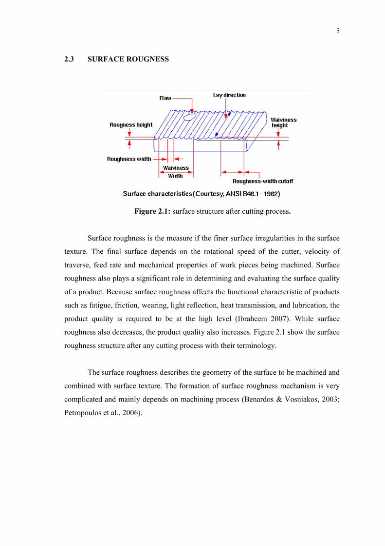
Figure 2.1: surface structure after cutting process.
Surface roughness is the measure if the finer surface irregularities in the surface
texture. The final surface depends on the rotational speed of the cutter, velocity of
traverse, feed rate and mechanical properties of work pieces being machined. Surface
roughness also plays a significant role in determining and evaluating the surface quality
of a product. Because surface roughness affects the functional characteristic of products
such as fatigue, friction, wearing, light reflection, heat transmission, and lubrication, the
product quality is required to be at the high level (Ibraheem 2007). While surface
roughness also decreases, the product quality also increases. Figure 2.1 show the surface
roughness structure after any cutting process with their terminology.
The surface roughness describes the geometry of the surface to be machined and
combined with surface texture. The formation of surface roughness mechanism is very
complicated and mainly depends on machining process (Benardos & Vosniakos, 2003;
Petropoulos et al., 2006).
6
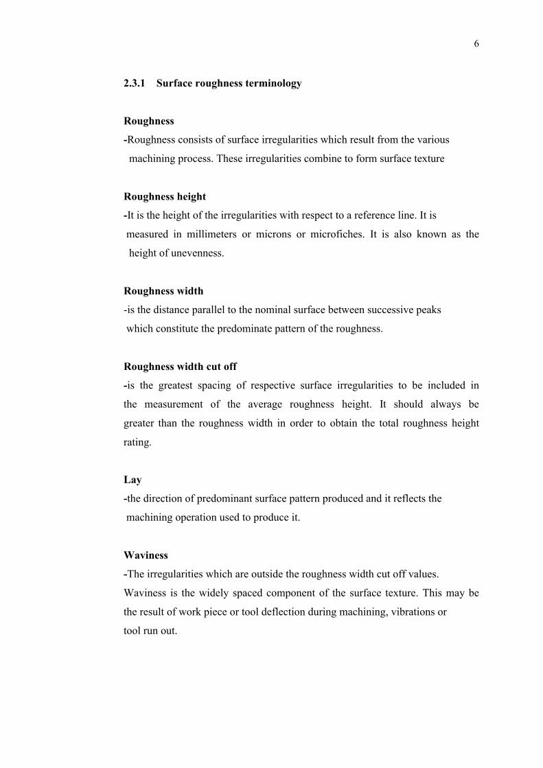
2.3.1 Surface roughness terminology
Roughness
-Roughness consists of surface irregularities which result from the various
machining process. These irregularities combine to form surface texture
Roughness height
-It is the height of the irregularities with respect to a reference line. It is
measured in millimeters or microns or microfiches. It is also known as the
height of unevenness.
Roughness width
-is the distance parallel to the nominal surface between successive peaks
which constitute the predominate pattern of the roughness.
Roughness width cut off
-is the greatest spacing of respective surface irregularities to be included in
the measurement of the average roughness height. It should always be
greater than the roughness width in order to obtain the total roughness height
rating.
Lay
-the direction of predominant surface pattern produced and it reflects the
machining operation used to produce it.
Waviness
-The irregularities which are outside the roughness width cut off values.
Waviness is the widely spaced component of the surface texture. This may be
the result of work piece or tool deflection during machining, vibrations or
tool run out.

7
Waviness width
- Waviness height is the peak to valley distance of the surface profile,
measured in millimeters.
2.3.2 Surface finish in machining
Ideal roughness
- is a function of only feed and geometry. It represents the best possible finish
which can be obtained for a given tool shape and feed. It can be achieved
only if the built-up-edge, chatter and inaccuracies in the machine tool
movements are eliminated completely.
Natural roughness
- In practice, it is not usually possible to achieve conditions such as those
described above, and normally the natural surface roughness forms a large
proportion of the actual roughness. One of the main factors contributing to
natural roughness is the occurrence of a built-up edge. Thus, larger the built
up edge, the rougher would be the surface produced, and factors tending to
reduce chip-tool friction and to eliminate or reduce the built-up edge would
give improved surface finish.
2.4 TURNING CARBON STEEL
Turning is a widely used machining process in which a single point cutting tool
removes material from the surface of a rotating cylindrical work piece. The lathe
machine uses a single-point-cutting tool for a variety of turning, facing, and drilling
jobs. Excess metal is removed by rotating the work piece over the fixed cutting tool to
form straight or tapered cylindrical shapes, grooves, shoulders and screw threads. It can
also be used for facing flat surfaces on the ends of cylindrical parts. The proper
selection of cutting tools and process parameters for achieving high cutting performance
in a turning operation is a critical task (Davim 2007)

8
Figure 2.2: conventional lathe machine
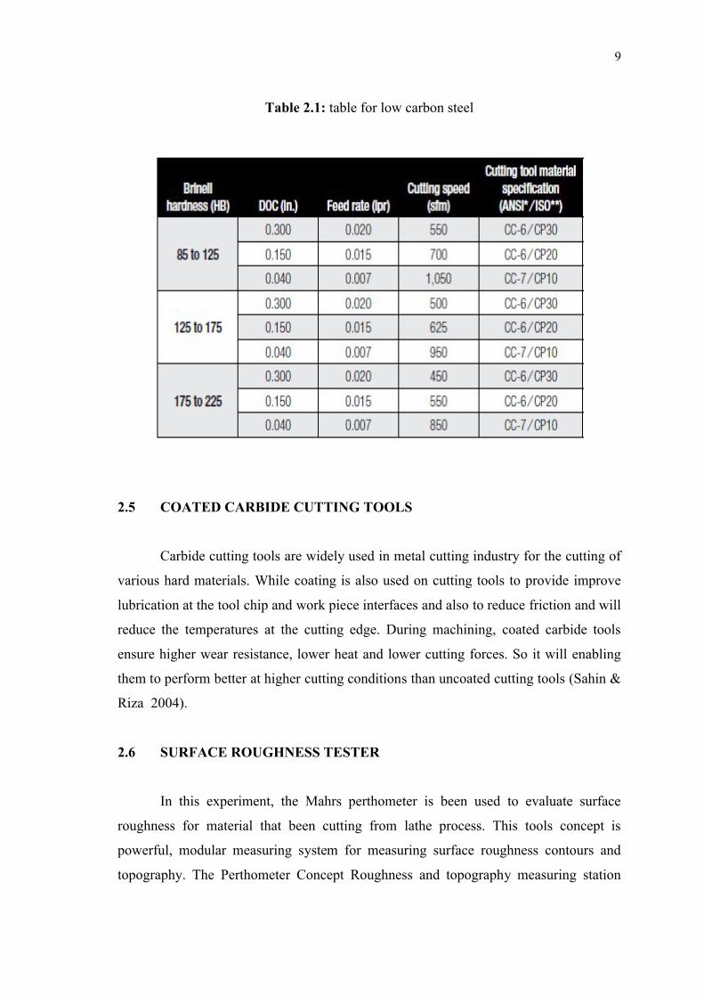
As for the carbon steel, its call the workhorse of the metalworking industry
where carbon steel is by far the most frequently machined steel. For low carbon steel
(Mild steel) are produced with 0.06 to 0.28 percent carbon and 0.25 to 1.00 manganese.
When turned, low carbon steels produce long chips which will form built up edge on an
indexable insert if a chipbreaker does not create a sufficient shear angle to curl the chip
away from the insert rake face.
Low cutting speed is another cause of BUE, which acts as an extension of the
cutting tool, changing part dimensions and imparting rough surface finishes. When
that’s the case, the cutting speed should be increased 15 to 20 percent or more until the
surface finish improves. The appropriate cutting speed depends on the depth of cut,
feed rate, cutting tool material and hardness of the work piece. Selecting the cutting
speed is always a challenge. Usually, the depth of cut and feed rate are conservative
parameters predetermined by whether it’s a roughing, semi finishing or finishing
operation (Isakov 2007). Table 2.1 indicated the recommendation or selection parameter
for low carbon steel.
9
Table 2.1: table for low carbon steel
2.5 COATED CARBIDE CUTTING TOOLS
Carbide cutting tools are widely used in metal cutting industry for the cutting of
various hard materials. While coating is also used on cutting tools to provide improve
lubrication at the tool chip and work piece interfaces and also to reduce friction and will
reduce the temperatures at the cutting edge. During machining, coated carbide tools
ensure higher wear resistance, lower heat and lower cutting forces. So it will enabling
them to perform better at higher cutting conditions than uncoated cutting tools (Sahin &
Riza 2004).
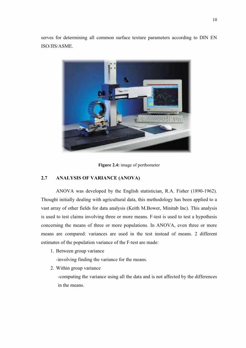
2.6 SURFACE ROUGHNESS TESTER
In this experiment, the Mahrs perthometer is been used to evaluate surface
roughness for material that been cutting from lathe process. This tools concept is
powerful, modular measuring system for measuring surface roughness contours and
topography. The Perthometer Concept Roughness and topography measuring station
10
serves for determining all common surface texture parameters according to DIN EN
ISO/JIS/ASME.
Figure 2.4: image of perthometer
2.7 ANALYSIS OF VARIANCE (ANOVA)
ANOVA was developed by the English statistician, R.A. Fisher (1890-1962).
Thought initially dealing with agricultural data, this methodology has been applied to a
vast array of other fields for data analysis (Keith M.Bower, Minitab Inc). This analysis
is used to test claims involving three or more means. F-test is used to test a hypothesis
concerning the means of three or more populations. In ANOVA, even three or more
means are compared: variances are used in the test instead of means. 2 different
estimates of the population variance of the F-test are made:
1. Between group variance
-involving finding the variance for the means.
2. Within group variance
-computing the variance using all the data and is not affected by the differences
in the means.
11
Since variation is a large part of the discussion relative to quality, analysis of
variation (ANOVA) is the statistical method used to interpret experimental data and
make necessary decisions. ANOVA is a statistically based decision tool for detecting
any differences in average performance of groups of items tested. ANOVA is a
mathematical technique which breaks total variation down into accountable sources and
total variation is decomposed into its appropriate components (Bhattacharya A., 2008)
Ozel et al.(2005) also conducted a set of analysis of variance (ANOVA) and
performed a detailed experimental investigation on the surface roughness and cutting
forces in the finish hard turning of AISI H13 steel. Their results indicated that the effect
of work piece hardness, cutting edge geometry, feed rate and cutting speed on surface
roughness are statistically significant besides the effect of two factor interaction of the
edge geometry and the feed rate and the cutting speed and the feed rate are also
important.
Escalona M., P. ,Cassier & Z. (1998) stated that the increase of the reed rate and
depth of cut results in a decrease in the critical cutting speed which is defined as the
cutting speed value above which poor quality and performance do not take place.Its
mean that, surface finish is more directly affected by feed rate, tool nose radius and
finally by the cutting speed.
2.8 MULTIPLE REGRESSION ANALYSIS
Regression analysis includes any techniques for modeling and analyzing several
variables, when the focus is on the relationship between a dependent variable and one or
more independent variables. More specifically, regression analysis helps us understand
how the typical value of the dependent variable changes when any one of the
independent variables is varied, while the other independent variables are held fixed.
The goal of regression analysis is to determine the values of parameters for a function
that cause the function to best fit a set of data observations that provided. In linear
regression, the function is a linear (straight-line) equation.

12
Figure 2.5: illustration of linear regression on data set
Figure 2.5 show the illustration of linear regression on example data set. It’s
indicated that the data have a relation that occurs to linear type and from there it can
provide an equation that related to data taken.
One should develop techniques to predict the surface roughness of a product
before turning in order to evaluate the robustness of machining parameters such as feed
rate or spindle speed for keeping a desired surface roughness in increasing product
quality. Researchers attempt to develop models which can predict surface finish of a
metal for a variety of machining conditions such as speed, feed, and dept of cut.
Reliable models would not only simplify manufacturing process planning and control
but would assist in optimizing machinability of materials (Hayajneh, 2007).