I INCH-POUND Ieveryspec.com/MIL-SPECS/MIL-SPECS-MIL-S/download.php?...o I INCH-POUND I MIL-S-45915A...
22
I INCH-POUND I o MIL-S-45915A 21 Auqust 1991 SUPERSEDING . . 0 0 STUD, LOCKED IN MIL-S-45915 1 December 1967 MILITARY SPECIFICATION - KEY LOCKED, GENERAL SPECIFICATION FOR 1. 1.1 This specification is approved for use by all Departments and Agencies of the Department of Defense. SCOPE SGQes - This specification covers locked in etuds which have integrated locking keys to prevent rotation of the stud when instilled in the tapped holes. 2. APPLICABLE DOCUMENTS 2.1 Government documents. 2.1.1 Specifications and standards. The following specifications, standards and handbooks form a part of this document to the extent specified herein. Unless otherwise epecified, the issuee of these documente are those listed in the issue of the Department of Defense Index of Specifications and Standards (DODISS) and supplement thereto, cited in the solicitation (see 6.2). SPECIFICATIONS FEDERAL QQ-A-225j8 - QQ-P-35 - QQ-P-416 - PPP-H-1581 - Aluminum Alloy 6061, Bar, Rod, Wire and Special Shapes, Rolled, Drawn or Cold Finished Passivation Treatments for Corrosion Resistant Steel Plating, Cadmium (Electrodeposited) Hardware (Fasteners and Related Items), Packaging of Beneficial comments (recommendations, additions, deletions) and any pertinent data which may be of use in improving this document should be addressed to: Commander, US Army Armament Research, Development and Engineering Center, ATTN: SMCAR-BAC-S, Picatinny Arsenal, NJ 07806-5000 by using the self-addressed Standardization Document Improvement Proposal (DD Form 1426) appearing at the end of this document or by letter. AMSC N/A FSC 5307 J31 STRIBUTION STATEMENT h. Approved for public release; distribution is unlimited. Downloaded from http://www.everyspec.com
Transcript of I INCH-POUND Ieveryspec.com/MIL-SPECS/MIL-SPECS-MIL-S/download.php?...o I INCH-POUND I MIL-S-45915A...
I INCH-POUND I
o MIL-S-45915A21 Auqust 1991SUPERSEDING
,.
I
.
0
0
STUD, LOCKED IN
MIL-S-459151 December 1967
MILITARY SPECIFICATION
- KEY LOCKED, GENERAL SPECIFICATION FOR
1.
1.1
This specification is approved for use by all Departmentsand Agencies of the Department of Defense.
SCOPE
SGQes - This specification covers locked in etuds which haveintegrated locking keys to prevent rotation of the stud wheninstilled in the tapped holes.
2. APPLICABLE DOCUMENTS
2.1 Government documents.
2.1.1 Specifications and standards. The following specifications,standards and handbooks form a part of this document to the extentspecified herein. Unless otherwise epecified, the issuee of thesedocumente are those listed in the issue of the Department of DefenseIndex of Specifications and Standards (DODISS) and supplementthereto, cited in the solicitation (see 6.2).
SPECIFICATIONS
FEDERAL
QQ-A-225j8 -
QQ-P-35 -
QQ-P-416 -PPP-H-1581 -
Aluminum Alloy 6061, Bar, Rod, Wire andSpecial Shapes, Rolled, Drawn or Cold FinishedPassivation Treatments for Corrosion ResistantSteelPlating, Cadmium (Electrodeposited)Hardware (Fasteners and Related Items),Packaging of
Beneficial comments (recommendations, additions, deletions) andany pertinent data which may be of use in improving this documentshould be addressed to: Commander, US Army Armament Research,Development and Engineering Center, ATTN: SMCAR-BAC-S, PicatinnyArsenal, NJ 07806-5000 by using the self-addressedStandardization Document Improvement Proposal (DD Form 1426)appearing at the end of this document or by letter.
AMSC N/A FSC 5307
J31STRIBUTION STATEMENT h. Approved for public release; distributionis unlimited.
Downloaded from http://www.everyspec.com
MIL-S-45915A
MILITARY
MIL-S-5626 -
MIL-H-6875 -
MIL-S-8879 -
MIL-I-17214 -
STANDARDS
FEDERAL
FED-STD-H28j2
FED-STD-H28/20 -
Steel, Chrome-Molybdenum (4140) Bars andReforging Stock (For Aircraft Applications)Heat Treatment of Steels (Aircraft PraCtiCe),Process forScrew Threads, Controlled Radius Root andIncreased Minor Diameter, General SpecificationforIndicator, Permeability; Low MU (Go-No Go)
MILITARY
MIL–STD-105
MIL-STD-1312/6MIL-STD-1312/8
MIL-STD-1312/13
MIL-STD-1949MIL-STD-6866MS51833MS51834MS51835
HANDBOOKS
MILITARY
ss‘1ssAT
;crew-Thread Standards for Federal;ervices, Section 2, Unified Inch Screw‘breads-UN and UNR Thread Forms.;crew-Thread Standards for Federal Services,;ection 20, Inspection Methods for~cceptability of UN, UNR, UNJ, M and MJ Screw-?hreads.
Sampling Procedures and Tables for Inspectionby AttributesFastener Test Methods, Method 6, HardnessFastener Test Methods, Method 8, TensileStrengthFastener Test Methods, Method 13, DoubleShearInspection, Magnetic ParticleInspection, Liquid PenetrantStud , Locked In, Key Locked, LightweightStud , Locked In, Key Locked, Heavy DutyInsert and Stud. Locked In. Kev Locked.Hole Dimensions
MIL-HDBK-57 - Listing of FastenerSymbols
for and Askembiy of ‘
Manufacturers f Identification
drawinas. and Duplications(Copies of specifications, standards,required by suppliers in connection with speci;ic proc~rementfunctions should be obtained from the procuring activity or asdirected by the contracting officer.)
2
Downloaded from http://www.everyspec.com
1
0
.
0
Q
MIL-S-45915A
2.2 Non-Government rmblications. The following documents form apart of this specification to the extent specified herein. Unlessotherwise specified, the issues of the documents which are DoDadopted are those listed in the issue of DODISS cited in thesolicitation. Unless otherwise specified, the issues not listed inthe DODISS are the issues of the documents cited in the solicitation(see 6.2).
AMERICAN MATERIAL SPECIFICATION (A14S)
AMS 5640 -
AMs 5731 -
AMs 5734 -
AHs 5737 -
AMS 5738 -AMS 6322 -
Steel Bars, Wire, andCorrosion ResistantSteel Bars, Forgings,Heat ResistantSteel Bars, Forgings,
Forgings, Free Machining,
Tubing, and Rings, Corrosion and
and Tubing, Corrosion and HeatResistantSteel Bars, Wire, Forgings, and Tubing, Corrosion andHeat ResistantSteel Bars, Free Machining, Corrosion ResistantSteel Bars, Forgings and Rings
(Applications for copies should be addressed to SAE International,400 Commonwealth Drive, Warrendale, PA 15096-0001.)
AMERICAN NATIONAL STANDARDS INSTITUTE (ANSI)
ASME B1.1 - Unified Inch Screw Threads (UN and UNR ThreadForm)
ANSIfASME B46.1 - Surface Texture (Surface Roughness, Wavinessand Lay)
(Applications for copies should be addressed to the AmericanNational Standards Institute, 11 West 42nd Street, 13th Floor,New York, NY 10036. or the American Society of Mechanical Engineers,345 East 47th Street, New York, NY 10017-2392.)
AMERICAN SOCIETY FOR TESTING AND MATERIALS (ASTM)
ASTH A 580 - Stainless and Heat-Resisting Steel WireASTM A 582 - Stainless and Heat-Resisting Steel Bars
(Applications for copies should be addressed to ASTM, 1916 RaceStreet, Philadelphia, PA 19103-1187.)
(Non-Government standards and other publications are normallyavailable from the organizations that prepare or that distribute thedocuments. These documents may also be available in or throughlibraries or other informational services.)
2.3 Order of wr ecedence. In the event of a conflict between thetext of this document and the references cited herein (except forrelated associated detail specifications, specification sheets or MSstandards) , the text of this document takes precedence. Nothing inthis document, however, supersedes applicable laws and regulationsunless a specific exemption has been obtained.
3
Downloaded from http://www.everyspec.com
MIL-S-45915A
3. REQUIREMENTS
3.1 Specification sheets. The individual item requirements shallbe as specified herein and in accordance with the applicablespecification sheet. In the event of any conflict between therequirements of this specification and the specification sheet, thelatter shall govern (see 6.2).
3.2 Material. Recycled and reclaimed materials shall be used tothe maximum extent practicable. Studs shall be fabricated of thefollowing materials, as specified (see 3.1) .
3.2.1 ?lllOV steel. Alloy steel shall be grade 4140 (UNS G41400)in accordance with MIL-S-5626 or grade 8740 (UNS G87400) inaccordance with AMS 6322.
3.2.2 Corrosion-resistant steel. Corrosion-resistant steel shallbe type 303 (UNS S30300) in accordance with AMS 5640 (Type 1) orASTM A 582, or type 303SE (UNS S30323) in accordance with AMS 5640(Type 2), AMS 5738 or ASTM A 582. Type A2S6 (UNS S66286) shall be inaccordance with AMS 5731, AMS 5734 or AMS 5737. Type A286 shall havemagnetic permeability of 2.0 maximum (Air = 1.0) for a field of H=200oersteds.
3.2.3 Lockinq kevs. Stud locking keys shall be made fromcorrosion-resistant steel, type 302, chemical composition ofASTM A 580 only.
3.3 Heat treatment. Studs made of alloy steel conforming toMIL-S-5626 or AMS 6322, and corrosion-resistant steel conforming toAMS 5731 or AMS 5734 shall be heat treated in accordance withMIL-H-6875 to develop the mechanical properties specified herein.
3.4 Cadmium wlatinq and surface treatment. Studs shall befurnished with a cadmium plating or surface treatment as specifiedherein and 3.1.
3.4.1 Alloy steel. Studs fabricated from alloy steel shall becadmium plated in accordance with QQ-P-416, Type II, Class 3, exceptstress durability test is not required. The entire stud shall becadmium plated. The locking keys may or may not be cadmium plated.
3.4.2 Corrosion-resistant steel. Studs fabricated from corrosion-resistant steel, less the keys, shall be passivated in accordancewith QQ-P-35. The key wire material shall be passivated inaccordance with QQ-P-35 prior to assembly in the stud.
3.5 Desiqn. dimensions and tolerance. Studs and locking keysshall be in accordance with the design, dimensions and tolerancesspecified in MS51833 or MS51834 as applicable (see 3.1) . Dimensionsand tolerances shall apply after application of the cadmium platingor surface treatment specified in 3.4.
3.5.1 Threads. Threads shall be right handed in accordance withthe applicable specification sheet (sse 3.1).
●
4
Downloaded from http://www.everyspec.com

I
I
o
0
0
MIL-S-45915A
3.5.1.1 )J~ . Nut end threads shall conform toMIL-S-8879, and shall be of the eizes specified in the applicablespecification sheet (see 3.1).
3.5.1.2 Stud end threads. Stud end threads shall conform toFED-STD-H28/2 . Minor diameters shall be as specified in theapplicable specification sheet (see 3.1).
3.5.1.3 Thr ead forminq. Threads for the nut end shall be fullyformed by a single rolling process subsequent to heat treatment andprior to plating or surface treatment. Threads for the stud end maybe produced either by machining, grinding, or fully formed by asingle rolling process prior to plating or surface treatment.
3.5.1.4 In comDlete thrcads. The runout threads shall be fairedinto the shank within a minimum of one and a maximum of two pitcheswithout an abrupt change in cross sectional area. Lead threads,including chamfer, shall not exceed two pitches. The root and flanksof the runout thread may deviate from true thread form but shall besmooth and free of tool marks.
3.5.1.5 Grain flow. The grain flow in rolled threads shall becontinuous and shall follow the general thread contour with themaximum density at the bottom of the root radius as shown infigure 1.
3.5.2plating,specification sheet (see 3.1) and shall be in accordance with
*p’’cMo”””c’FIGURE 1. Thr ead arai.n fl Ow
Surf ace texture. The surface texture ofshall not exceed the values specified in
the stud prior tothe applicable
AiiSI/ASFIE B46.1 when tested in conformance with 4.3.2.6.
5
Downloaded from http://www.everyspec.com

MIL-S-45915A
3.5.3 Straightnessthe values specified4.3.2.5.
TABLE I
,
The straightness of ths stud shalln table I when tested in conformance
Allowable deviation of the stud
Basic Stud Size I Deviation of Stud - Maximum(Nut End) (Inches per Inch of Nut End Length)
be withinwith
I
.190 and smaller
.250 - .3125
.375 - .4375
.5OO and larger
0.00400.00300.00250.0020
3.6 Mechanical properties. Studs conforming to the design anddimensions specified in the applicable specification sheet (see 3.1)and having load ratings as specified in tables IIa and IIb shall becapable of developing for a ultimate tensile strength and a minimumproof strength the values for ultimate tensile stress specified intables IIa and IIb.
3.6.1 Tensile strenath.proof loads as specified inconformance with 4.3.3.1.
TABLE IIa. Minimum tensile
The stud shalltables IIa and
be capable of withstandingIIb when tested in
strenath of studs - coarse threads (UNJC)
~BasicSize;Nut End)
.164
.190
.250
.3125
.375
.4375
.500
.5625
.625750:875
1.000
l/
~1
StressAreainz ~/UNJC
.0140
.0175
.0318
.0524
.0775
.1063
.1419
.1820
.2260
.3340
.4620
.6060
Tensile Load - Lbs
80,000 psi(303/303SE)
~/
1,1201,4002,5444,1926,2008,504
11,35214,56018,08026,72036,96048,480
140,000 psi(A286)2/
1,9602,4504,4527,336
10,85014,88219,86625,48031,64046,76064,68084,840
Tensile stress areas per ASME B1.1
160,000 psi(4140/8740)
21
2,2402,8005,0888,384
12,40017,00822,70429,12036,16053,44073,92096,960
Stud material minimum ultimate tensile strength.
6
●
●
●
Downloaded from http://www.everyspec.com

MIL-S-45915A
I
I
I
I
w
o
Tensile Load - LbsStress
Basic Area 80,000 pSi 140,000 psi 160,000 psiSize in’ 1/ (303/303SE) (A286) (4140/8740)[Nut End) UNJF 2/ 2/ 21
164 .01474 1,179 2,063 2,358:190 .0200 1,600 2,800 3,200.250 .0364 2,912 5,096 5,824.3125 .0580 4,640 8,120 9,280.375 .0878 7,024 12,292 14,048.4375 1187 9,496 16,618 18,992.500 :1599 12,792 22,386 25,584.5625 .2030 16,240 28,420 32,480.625 .2560 20,480 35,840 40,960.750 3730 29,840 52,220 59,680.875 :5090 40,720 71,260 81,440
1.000 .6630” 53,040 92,820 106,080
M Tensile stress areas per ASME B1.1
21 Stud material minimum ultimate tensile strength.
, 07
Downloaded from http://www.everyspec.com

MIL-S-45915A
3.6.2 Resistance to DUllOUt. The installed stud (with or withoutlocking keys installed) shall have a minimum resistance to pullout asspecified in table III when installed in a test block and tested inconformance with 4.3.3.2.
TABLE III. Resistance to Pullout
Studs Per MS51833 Studs Per MS51834
Minimum MinimumShear Minimum Shear Minimum
Basic Engagement Pullout Engagement PulloutSize Area Load Area Load(Nut End) ina JJ Lbs. ~1 in’J ~~ Lbs . ~/
.164 -- -- 1517 4,096
.190 .1517 4,096 :1901
.2505,133
.2371 6,402 .2842 7,673.3125 3049 8,232 .3588 9,688.375 :4299 11,607 .4975 13,433.4375 .5665 15,296 .7172 19,364500 .7172 19,364 .8884 23,987:5625 1.2493 33,731.625 1.4866.750
40,1382.4901 67,233
.875 3.1370 84,6991.000 3.8381 103,629
~j Shear engagement area is an unassembled dimensional value forthe overall engaged area of the mating thread member. It doesnot represent a dimension of either of the members in anunassembled condition.
~1 Pullout load = (Shear engagement area) x (27,000 psi). Tocompute minimum pullout load in other materials, multiply shearengagement area by the applicable minimum ultimate shearstrength of the material.
8
Downloaded from http://www.everyspec.com

MIL-S-45915A
o 3.6.3 Rotational resistance. The installed stud shall haveminimum resistance to torque out as specified in table IV whenin conformance with 4.3.3.3.
L
TABLE IV. flinimum tora ue out req uir ements
Basic Studs Per MS51833 Studs Per HS51834Size(Nut End) Torque, Inch-pounds Torque, Inch-pounds
.164 -- 72
.190 72 110
.250 120 180
.3125 240 360
.375 320 480
.4375 400 600
.500 600 900
.5625 1,200
.625 1,800
.750 2,400
.875 3,6001.000 4,800
atested
o 3.6.4 Hardness. Alloy steel studs shall meet the hardness asspecified in the applicable specification sheet (see 3.1) when testedin conformance with 4.3.3.4.
3.7 )4etallurqi.cal ur opert ies.
3.7.1 13iscontin uities. Studs shallwhich exceed the following limitationswith 4.3.3.6.
not contain discontinuitieswhen examined in conformance
3.7.1.1 Cracks (see 6.3.ll_. Studs shall be free of cracks in anydirection or location when examined in conformance with 4.3.3.6.
6
9
Downloaded from http://www.everyspec.com

MIL-S-45915A
3.7.1.2 La s and seamsD (see 6.3.2 and 6.3.3)-. Studs may possesslaps and seams, except in locations as shown in fiqure Z.Permissible laps and-seams as shown in figure 2 shill not exceed thedepths sDecified in table V. Care must be exercised not to confusecracks with inclusions, as specified herein.
TABLE V. Maximum discontinuity deDth
Basic stud size Discontinuity depth(Nut end) in inches, max ~/
.164 thru .3125 0.005
.375 0.006
.4375 0.007
.500 thru 1.000 0.008
~/
3.7.1.3
Depth of discontinuity shall be mea.aur~d no~mal to thesurface at a point of-greatest penetration
Inclusions (see 6.3.4). Studs shall show no evidence ofsurface or subsurface inclusions a~ the thread root as shown infigure 2 when examined in conformance with 4.3.3.6.
3.7.2 Grindinq Burns. The studs shall show no visual evidence ofgrinding burns.
3.8 Source identification mark. The stud shall be marked on thekey tang or stud. The source identification insignia for amanufacturer shall be in accordance with MIL-HDBK-57 or a privatelabel distributors insignia as applicable. The sourceidentification mark shall be legible and permanent.
3.9 Workmanship. Workmanship shall be consistent with the type ofproduct, finish, and class of thread fit specified. Studs shall beof uniform quality and free from defects which would be detrimentalto the performance of the stud.
10
Downloaded from http://www.everyspec.com

MIL-S-45915A
Laps, seems andinclusionst-d permissible
MAJOR DIAXTCR
—PITCH DIAAETER
- — - — UIMJR oIAMETER
FIGURE 2. MD s. seams, inelusions and surface irr eqular ities inreads
11
Downloaded from http://www.everyspec.com
MIL-S-45915A
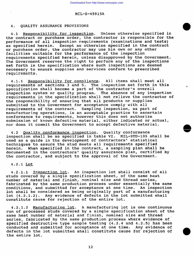
4. QUALITY ASSURANCE PROVISIONS
4.1 ResDonsibilitv for inspection. Unless otherwise specified inthe contract or purchase order, the contractor is responsible for theperformance of all inspection requirements (examinations and tests)as specified herein. Except as otherwise specified in the contractor purchase order, the contractor may use his own or any otherfacilities suitable for the performance of the inspectionrequirements specified herein, unless disapproved by the Government.The Government reserves the right to perform any of the inspectionsset forth in the specification where such inspections are deemednecessary to ensure supplies and services conform to prescribedrequirements.
4.1.1 Responsibility for compliance. All items shall meet allrequirements of sections 3 and 5. The inspection set forth in thisspecification shall become a part of the contractor’s overallinspection system or quality program. The absence of any inspectionrequirements in the specification shall not relieve the contractor ofthe responsibility of ensuring that all products or suppliessubmitted to the Government for acceptance comply with allrequirements of the contract. Sampling inspection, as part ofmanufacturing operations, is an acceptable practice to ascertainconformance to requirements, however this does not authorizesubmission of known defective material, either indicated or actual,nor does it commit the Government to accept defective material.
4.2 f)ualitv conformance inspection. Quality conformanceinspection shall be as specified in table VI. MIL-STD-105 shall beused as a guide in the development of contractors’ statisticaltechniques to assure the stud meets all requirements specifiedherein. When specified in the contract, a sampling plan shall bedocumented in the contractors’ quality assurance plan, certified bythe contractor, and subject to the approval of the Government.
4.2.1 ~
4.2.1.1 Inspection lot. An inspection lot shall consist of allstuds covered by a single specification sheet, of the same heatnumber of material and finish, nominal size and thread series,fabricated by the same production process under essentially the sameconditions, and submitted for acceptance at one time. An inspectionlot shall be considered as being originally part of a manufacturinglot (4.2.1.2). Any evidence of defects in the lot submitted shallconstitute cause for rejection of the entire lot.
4.2.1.2 Manufacturing lot. A manufacturing lot is one continuousrun of processed studs covered by a single specification sheet of thesame heat number of material and finish, nominal size and threadseries, fabricated by the same production process where evidence of”specified destructive type sample testing (4.2.4 and 4.2.5) has beenconducted and submitted for acceptance at one time. Any evidence ofdefects in the lot submitted shall constitute cause for rejection ofthe entire lot.
12
Downloaded from http://www.everyspec.com

MIL-S-45915A
o 4.2.2 Reiected lots . If an inspection lot is rejected, thecontractor may rework it to correct the defects, or ecreen out thedefective units, and resubmit for inspection. Resubmitted lote shallbe in accordance with 4.2. Such lots shall be separate from newlots, and shall be clearly identified as re-inspected lots.
TABLE VI. pualit’f conformance inspection
o
Inspection Requirement TestParagraph Paragraph
GrOUD AMaterial 3.2 4.3.3.5Heat treatment 3.3 4.3.3.4Cadmium plating 3.4.1 4.3.2.3Passivation 3.4.2 4.3.2.4Dimensions 3.5 4.3.2.7Straightness 3.5.3 4.3.2.5Grinding burns 3.7.2 4.3.2.7Source identification 3.8 4.3.2.7Workmanship 3.9 4.3.2.7
GrOUD ElMagnetic permeability 3.2.2 4.3.3.8Threads 3.5.1 4.3.2.2Surface texture 3.5.2 4.3.2.6
GrOUD CGrain flow 3.5.1.5 4.3.3.7Tensile strength (proof) 3.6.1 4.3.3.1Resistance to pullout (proof) 3.6.2 4.3.3.2Rotational resistance (proof) 3.6.3 4.3.3.3Hardness 3.6.4 4.3.3.4Discontinuities 3.7.1 4.3.3.6Cracks 3,7.1.1 4.3.3.6Laps and seams 3.7.1.2 4.3.3.6Inclusions 3.7.1.3 4.3.3.6
013
Downloaded from http://www.everyspec.com
NIL-S-45915A
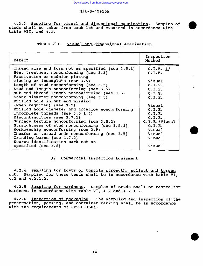
4.2.3 Samulina for visual and dimensional examination. Samples ofstuds shall be taken from each lot and examined in accordance Withtable VII, and 4.2.
TABLE VII. Visual and dimensional examination
InspectionDefect Method
Thread size and form not as specified (see 3.5.1) C.I.E. ifHeat treatment nonconforming (see 3.3) C.I.E.Passivation or cadmium platingmissing or incomplete (see 3.4) VisualLength of stud nonconforming (see 3.5) C.I.E.Stud end length nonconforming (see 3.5) C.I.E.Nut end thread length nonconforming (see 3.5) C.I.E.Shank diameter nonconforming (see 3.5) C.I.E.Drilled hole in nut end missing(when required) (see 3.5) VisualDrilled hole diameter and location nonconforming C.I.E.Incomplete threads (see 3.5.1.4) C.I.E.Discontinuities (see 3.7.1) C.I.E.Surface texture nonconforming (see 3.5.2) C.I.E./VisualStraightness of stud nonconforming (see 3.5.3) C.I.E.Workmanship nonconforming (see 3.9) VisualChamfer on thread ends nonconforming (see 3.5) VisualGrinding burns (see 3.7.2) VisualSource identification mark not asspecified (see 3.8) Visual
JJ Commercial Inspection Equipment
4.2.4 Samulinq for tests of tensile strenqth,Q@.
DullOut and torqueSampling for these tests shall be in accordance with table VI,
4.2 and 4.2.1.2.
4.2.5 Samplinq for hardness. Samples of studs shall be tested forhardness in accordance with table VI, 4.2 and 4.2.1.2.
4.2.6 Inspection of DaCkaclinq. The sampling and inspection of thepreservation, packing, and container marking shall be in accordancewith the requirements of PPP-H-1581.
14
Downloaded from http://www.everyspec.com
MIL-S-45915A
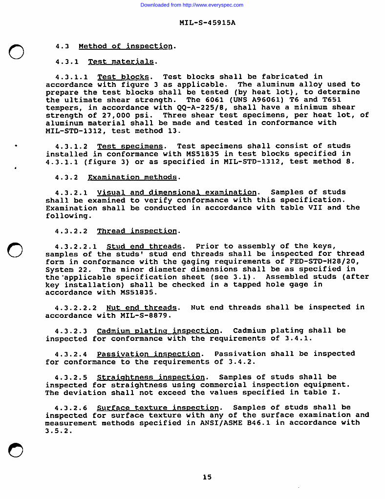
4.3 Method of insDectioU.
4.3.1 rest materials.
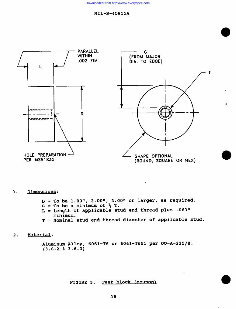
4.3.1.1 Test blocks. Test blocks shall be fabricated inaccordance with figure 3 as applicable. The aluminum alloy used toprepare the test blocks shall be tested (by heat lot), to determinethe ultimate shear strength. The 6061 (UNS A96061) T6 and T651tempers, in accordance with QQ-A-225/8, shall have a minimum shearstrength of 27,000 psi. Three shear test specimens, per heat lot, ofaluminum material shall be made and tested in conformance withMIL-STD-1312, test method 13.
4.3.1.2 Test sDecimens. Test specimens shall consist of studsinstalled in conformance with MS51835 in test blocks specified in4.3.1.1 (figure 3) or as specified in MIL-STD-1312, test method 8.
4.3.2 Exam ination methods.
4.3.2.1 Visual and dim ensional examination. Samples of studsshall be examined to verify conformance with this specification.Examination shall be conducted in accordance with table VII and thefollowing.
4.3.2.2 Thread inspection.
4.3.2.2.1 Stud end threads. Prior to assembly of the keys,samples of the studs’ stud end threads shall be inspected for threadform in conformance with the gaging requirements of FED-STD-H28/20,System 22. The minor diameter dimensions shall be as specified inthe-applicable specification sheet (see 3.1). Assembled studs (afterkey installation) shall be checked in a tapped hole gage inaccordance with MS51835.
4.3.2.2.2 Nut end threads. Nut end threads shall be inspected inaccordance with MIL-S-8879.
4.3.2.3 Cadmium D~ atina inspection. Cadmium plating shall beinspected for conformance with the requirements of 3.4.1.
4.3.2.4 Passivation inspection. Passivation shall be inspectedfor conformance to the requirements of 3.4.2.
4.3.2.5 Straic!htness insDectio~. Samples of studs shall beinspected for straightness using commercial inspection equipment.The deviation shall not exceed the values specified in table I.
4.3.2.6 Sur face texture inspection. Samples of studs shall beinepected for surface texture with any of the surface examination andmeasurement methods specified in ANSI/ASME B46.1 in accordance with3.5.2.
15
Downloaded from http://www.everyspec.com
v
MIL-S-45915A
●
.---_-J ---------
----------------
\
PARALLELWITHIN.002 FIM r(FROM ‘MAJOR
OIA. TO EDGE)
HOLE PREPARATION 2 LPER MS51835
SHAPE OPTIONAL(ROUND, SQUARE OR HEX)
1. Dimensions:
D = To be 1.00”, 2.00”, 3.oo” or larger, as required.G = To be a minimum of ~ T.L = Length of applicable stud end thread plus .063”
minimum.T = Nominal stud end thread diameter of applicable stud.
2. Material:
Aluminum A11oY, 6061-T6 or 6061-T651 Per QQ-A-225/8.(3.6.2 & 3.6.3)
..
FIGURE 3. Test block lCOUDOI-11
16
Downloaded from http://www.everyspec.com

MIL-S-45915A
o 4.3.2.7 dimensions. m indinq burns. source identif ication m rk andworkmanship. Dimensions, grinding burns, source identification; markand workmanship shall be inspected visually to determine conformancewith the requirements of 3.5, 3.7.2, 3.8 and 3.9.
4.3.3 Test methods.
4.3.3.1 Tensile strena th (orOof) test. Nut end threads of thestud shall be tested in conformance with MIL-STD-1312, test method 8,in tension between the nut end and the stud end to meet therequirements of 3.6.1. Fixtures shown in figure 4 may also be used.Samples shall be of sufficient length to develop the full strength of
, the nut end thread of the stud without stripping the thread.
4.3.3.2 Resistance to Pull (pr f)out 00.
test. Test specimens ofstuds shall be installed in test blocks (figure 3) as specified in4.3.1.1. The stud shall then be assembled in a fixture as shown infigure 4 or in accordance with MIL-STD-1312, test method 8. Theaxial load shall be applied at a rate not to exceed 100,000 psi perminute based on the minimum shank diameter of the stud to meet therequirements of 3.6.2. The test shall be considered successful ifthe stud pulls out or remains in the test block at the minimum valuesshown in table III or the nut end of the stud fails at or above thevalues shown in tables IIa or IIb.
o 4.3.3.3 130tat” es~ 00 test. Test specimens ofstuds shall be installed in test blocks (figure 3) as specified in4.3.1.1. Torque-out values, with no axial load on the stud, shallmeet the requirements SDeCified in 3.6.3. The rotational force is tobe appliedFailure ofrejection.
4.3.3.4tested for
;ith a torqu; wrench in a counter-clockwise direction.the stud to remain in the test block shall be cause for
Liardness test. Samples of alloy steel studs shall behardnees requirements of 3.6.4. in accordance with
MIL-STD-1312, test method 6.
4.3.3.5 Bl w a eri inspection. Raw material chemical analysiscertification may be accepted in lieu of test data.
o17
Downloaded from http://www.everyspec.com

MIL-S-45915A
~ uPPER YOKE
1 LOWER YOKESPECIFIED IN 4.3.1.2
OPTION 13 THREAD PITCHES, MAX2 THREAD PITCHES. MIN
r UPPER YOKE
,03 MAX
= +.D1O +.005I
// ~ BUSHING
~ THREAOEO
t
I DIRE~TIONOF LOAD
LOWER YOKE
TEST SPECIMEN AS -/
SPEClflEO IN 4.3.1.2
++- 2X .03 MAX
OPTION 2
FIGURE 4. Resistance to gullout fixture [ogtions)
18
Downloaded from http://www.everyspec.com

MIL-S-45915A
o
,
0
0
4.3.3.6 “Sco t“~. Samples of studs shall beinspected for discontinuities such as cracks, laps, seams andinclusions in accordance with 3.7. Any crack detected during visualexamination shall be cause for rejection of the lot. When visualevidence of discontinuities show cause for further inspection, samplestuds shall be subjected to magnetic particle inspection performed inaccordance with MIL-STD-1949 for alloy steel, fluorescent penetrantinspection performed in accordance with MIL-STD-6866 for corrosion-resistant steel. Magnetic particle or penetrant inspectionindications alone shall not be cause for rejection. If indicationsare considered cause for rejection, representative samples shall betaken from those studs showing indication and these samples shall befurther examined. Studs may be sectioned as shown in figure 5 andshall be inspected parallel to the axis. Discontinuities aremeaeured microscopically under 100 X magnification to determineconformance to the requirements of 3.7.1. The inspection shall beperformed on finished studs subsequent to any processing operationwhich could adversely affect the studs.
4.3.3.7 Grain flow inspectio~. Sample studs shall bemicroexamined to determine compliance with the requirements of3.5.1.5 grain flow for rolled threads. Specimens shall be taken fromthe stud as shown in figure 5. The studs shall be etched in asuitable etchant for sufficient time to reveal the microstructureproperly.
o
A -’l “ r0/2
————
—-— .
1-—— u
t v i
CUT HER[ fOR sSPECIMENS TO BEUACROCXAUINEO
FIGURE 5. Hetallur aical snecimen
4.3.3.8 B etaan ic Dermeabili tv test. Austenitic corrosion-resistant steel studs, subjected to visual and dimensionalexamination, shall also be tested to determine magnetic permeability(see 3.2.2) in accordance with MIL-I-17214.
19
Downloaded from http://www.everyspec.com
MIL-S-45915A
5.
5.1be in
6.
(This
PACKAGING
Packaqina requirements. The requirements for packaging shallaccordance with PPP-H-1581 (see 6.2c) .
NOTES
section contains information of a general or explanatory naturethat may be helpful, but is not mandatory.)
6.1 Intended use. Studs covered by this specification areintended as a general purpose fastener with depth locating keys and amechanical lock to resist rotation when installed.
6.2 Acquisition reauirements. Acquisition documents shouldspecify the following:
a. Title, number and date of this specification andapplicable specification sheet.
b. Applicable specification sheet part number (see 3.1).c. Level (degree) of protection in accordance with
PPP-H-1581, ordering data (see 5.1) .
6.3 Definitions
6.3.1 Crack. Athe grain or grainelements.
crack is a cleanboundary without
crystalline break passi,ng throughthe inclusion of foreign
6.3.2 ~. A lap is a surface defect appearinq as a seam, causedby the folding over-of metal fins or sharp-korner; and then rollingor forging them into the surface, but not welding them.
6.3.3 ~. A seam is an unwelded fold or lap which appears as anopening in the raw material as received from the source.
6.3.4 Inclusions. Inclusions are non-metallic materials in asolid metallic matrix.
6.4 Kev word listinq.Lightweight studLocked in studLocking keysHeavy duty studKey locked stud
6.5 Chanqes from previous issue. Marginal notations are not usedin this revision to identify changes with respect to the previousissue due to the extensiveness of the changes.
;
●
20
Downloaded from http://www.everyspec.com
I
I
~ oi
.
MIL-S-45915A
Custodians:Army - ARNavy - ASAir Force - 99
Review ActivitiesArmy - AV, MINavy - SHAir Force - 82DLA - IS
User ActivitiesArmy - AT, ERNavy - MC
/
o
021
Preparing Activity:Army - AR
(Project No. 5307-0542)
Downloaded from http://www.everyspec.com
STANDARDIZATION DOCUMENT IMPROVEMENT PROPOSAL
1. The preparing actMty must comploto blocks 1, 2, 3, and 8. In block 1. both the document number and revision
Ielter should be gfven.
2. The submitter of thlo form must complete blocko 4, 5, 8, and 7.
L The preparino actMty muet provide e repty wiihln 30 daye from receipt of the form.
UOTE This form may not bo used to request coplee of documente, nor to requeet wafvere. Or ckfflCi3110n of
,equlremente on current Contrects. Commente eubmltted on Ihle form do not Conslltule or lmpfy authorization to
mfva any pmilon of the referenced document(c) or to ●mend contmctuel requkemenm.
1 RECOMMEND A CHANGE: I ‘“ ‘~Ly&lm2. 00cuw.Nl MrE ,Whlmnm
21 August 1991
“‘m - STUD, LOCKED IN - KEY LOCKED, GENERAL SPECIFICATION FOR
?uNRE OFC- RMfW DUW4XI — m lrcti _ fO.W1t., II -. u1ti -u. mfi U-.1
R- FOR~ECOMM_TWN
f+uwmmnNAha (u.. Fbrt. - bwml b. =-1’tON
-!2ss (-Z* QO=J a, ‘rE1.EU+ONf m- NO* -) 7. cmmm~mw
111 —1.1
m ~OVON(dM@cnaw
rUEPAR?mUxmm
“~&f%&D%i SW’tdardWftlcm Oflice
u,Tm.Emoa 1-- -}
‘“ m?;4-6626 &~6=1.AnOmm@@xam -) @VOU00 NOTREG- A RE-V WITMNu mm, CoNrAcT:
ATTtd: SMCAR-BAC-Smmn.. Ou.lw d St-z.tti OlncO
Picatinny Arsenal. NJ 07606-500062MLwaauaPIm mm *MX S.119CIUWI,VA=IaT.!- m) — UlmVON —
. . ..”. ,“9R nt-r 90 -b,,. “+;,;.. . ““ ,+””l”. ISW?.M. r“,,!. !..”, ““o “. . . . ..— --.-.. -. —.-
—.
Downloaded from http://www.everyspec.com


![[INCH-POUND] oeveryspec.com/MIL-SPECS/MIL-SPECS-MIL-O/download.php?... · MIL-O-2721OF o the issues of documents not listed in the DODISS shall be the issue of the nongoverument documents](https://static.fdocuments.net/doc/165x107/5ea1e09d81612f5163528fa2/inch-pound-mil-o-2721of-o-the-issues-of-documents-not-listed-in-the-dodiss-shall.jpg)