
I Ill11 ll111111 Ill Ill11 Ill11 IIIII IIIII IIIII IIIII ... · PDF fileI Ill11 ll111111 Ill...
34
I I l l 11 l 111111 Ill I l l 11 I l l 11 IIIII IIIII IIIII IIIII I l l 11 I l l 11 11111111111111 I l 1 (12) United States Patent Thiesen et al. (54) MINIATURE RECIPROCATING HEAT PUMPS AND ENGINES (75) Inventors: Jack H. Thiesen, Longmont, CO (US); Gary S. Willen, Boulder, CO (US); Robert A. Mohling, Boulder, CO (US) (73) Assignee: Technology Applications, Inc., Boulder, CO (US) Subject to any disclaimer, the term of this patent is extended or adjusted under 35 U.S.C. 154(b) by 0 days. ( * ) Notice: (21) Appl. No.: 101074,366 (22) Filed: Feb. 12, 2002 (65) Prior Publication Data US 200310101732 A9 Jun. 5, 2003 Related U.S. Application Data (60) Provisional application No. 601268,523, filed on Feb. 13, 2001, and provisional application No. 601331,883, filed on Nov. 20, 2001. (51) Int. C1.7 ................................................... F25B 9/00 (52) U.S. C1. ...................... 6216; 6213.1; 621457; 91142; 601636 (58) Field of Search ............................... 6216, 3.1, 457; 91142; 601636 (56) References Cited U.S. PATENT DOCUMENTS 3,095,785 A * 3,230,838 A * 4,392,362 A 4,417,448 A * 4,671,080 A 4,829,785 A 5,148,066 A * 5,269,372 A 5,323,999 A 5,336,062 A 5,380,396 A 711963 111966 711983 1111983 611987 511989 911992 1211993 611994 811994 111995 Cahill ........................... 91142 Westbrook ..................... 91142 Little .......................... 621514 Horn et al. ...................... 6216 Gross .......................... 621467 Hersey ........................ 621467 Beale et al. ..................... 6216 Chu et al. .................. 165180.4 Bonne et al. ................. 251111 Richter ................... 4171413 A Shikida et al. .............. 1561630 (io) Patent No.: (45) Date of Patent: US 6,595,006 B2 Jul. 22,2003 5,417,235 A 5,436,793 A 5,441,597 A 5,457,956 A 5,491,363 A 5,696,405 A 5,699,668 A * 5,763,998 A 5,788,468 A 5,871,336 A 5,932,940 A 5,941,079 A * 5,981,071 A 511995 711995 811995 1011995 211996 1211997 1211997 611998 811998 211999 811999 811999 1111999 Wise et al. .................... 13711 Sanwo et al. ............... 3611689 Bonne et al. .................. 21612 Bowman et al. .............. 601520 Yoshikawa .................. 2571715 Weld .......................... 2571714 Cox ............................. 6213.1 Colombo et al. ........... 3131495 Dewa et al. ................ 4171415 Young ........................ 4171207 Epstein et al. ........ 310140 MM Bowman et al. ................. 6216 Cox ........................... 4281408 (List continued on next page.) OTHER PUBLICATIONS Bailey, D.K. et al., “Single phase forced convection heat transfer in microgeometries-a review,” IECEC Paper No. ES-396 (1995) pp 301-310. (List continued on next page.) Primary Examinerqonald Capossela (74) Attorney, Agent, or Firm4reenlee, Winner and Sullivan, P.C. ABSTRACT The present invention discloses a miniature thermodynamic device that can be constructed using standard micro- fabrication techniques. The device can be used to provide cooling, generate power, compress gases, pump fluids and reduce pressure below ambient (operate as a vacuum pump). Embodiments of the invention relating to the production of a cooling effect and the generation of electrical power, change the thermodynamic state of the system by extracting energy from a pressurized fluid. Energy extraction is attained using an expansion process, which is as nearly isentropic as possible for the appropriately chosen fluid. An isentropic expansion occurs when a compressed gas does work to expand, and in the disclosed embodiments, the gas does work by overcoming either an electrostatic or a mag- netic force. (57) 29 Claims, 13 Drawing Sheets https://ntrs.nasa.gov/search.jsp?R=20080007076 2018-05-07T01:14:36+00:00Z
Transcript of I Ill11 ll111111 Ill Ill11 Ill11 IIIII IIIII IIIII IIIII ... · PDF fileI Ill11 ll111111 Ill...
I Ill11 ll111111 Ill Ill11 Ill11 IIIII IIIII IIIII IIIII Ill11 Ill11 11111111111111 Ill1 (12) United States Patent
Thiesen et al.
(54) MINIATURE RECIPROCATING HEAT PUMPS AND ENGINES
(75) Inventors: Jack H. Thiesen, Longmont, CO (US); Gary S. Willen, Boulder, CO (US); Robert A. Mohling, Boulder, CO (US)
(73) Assignee: Technology Applications, Inc., Boulder, CO (US)
Subject to any disclaimer, the term of this patent is extended or adjusted under 35 U.S.C. 154(b) by 0 days.
( * ) Notice:
(21) Appl. No.: 101074,366
(22) Filed: Feb. 12, 2002
(65) Prior Publication Data
US 200310101732 A9 Jun. 5, 2003
Related U.S. Application Data (60) Provisional application No. 601268,523, filed on Feb. 13,
2001, and provisional application No. 601331,883, filed on Nov. 20, 2001.
(51) Int. C1.7 ................................................... F25B 9/00
(52) U.S. C1. ...................... 6216; 6213.1; 621457; 91142; 601636
(58) Field of Search ............................... 6216, 3.1, 457; 91142; 601636
(56) References Cited
U.S. PATENT DOCUMENTS
3,095,785 A * 3,230,838 A * 4,392,362 A 4,417,448 A * 4,671,080 A 4,829,785 A 5,148,066 A * 5,269,372 A 5,323,999 A 5,336,062 A 5,380,396 A
711963 111966 711983
1111983 611987 511989 911992
1211993 611994 811994 111995
Cahill ........................... 91142 Westbrook ..................... 91142 Little .......................... 621514 Horn et al. ...................... 6216 Gross .......................... 621467 Hersey ........................ 621467 Beale et al. ..................... 6216 Chu et al. .................. 165180.4 Bonne et al. ................. 251111 Richter ................... 4171413 A Shikida et al. .............. 1561630
(io) Patent No.: (45) Date of Patent:
US 6,595,006 B2 Jul. 22,2003
5,417,235 A 5,436,793 A 5,441,597 A 5,457,956 A 5,491,363 A 5,696,405 A 5,699,668 A * 5,763,998 A 5,788,468 A 5,871,336 A 5,932,940 A 5,941,079 A * 5,981,071 A
511995 711995 811995
1011995 211996
1211997 1211997 611998 811998 211999 811999 811999
1111999
Wise et al. .................... 13711 Sanwo et al. ............... 3611689 Bonne et al. .................. 21612 Bowman et al. .............. 601520 Yoshikawa .................. 2571715 Weld .......................... 2571714 Cox ............................. 6213.1 Colombo et al. ........... 3131495 Dewa et al. ................ 4171415 Young ........................ 4171207 Epstein et al. ........ 310140 MM Bowman et al. ................. 6216 Cox ........................... 4281408
(List continued on next page.)
OTHER PUBLICATIONS
Bailey, D.K. et al., “Single phase forced convection heat transfer in microgeometries-a review,” IECEC Paper No. ES-396 (1995) pp 301-310.
(List continued on next page.)
Primary Examinerqonald Capossela (74) Attorney, Agent, or Fi rm4reen lee , Winner and Sullivan, P.C.
ABSTRACT
The present invention discloses a miniature thermodynamic device that can be constructed using standard micro- fabrication techniques. The device can be used to provide cooling, generate power, compress gases, pump fluids and reduce pressure below ambient (operate as a vacuum pump). Embodiments of the invention relating to the production of a cooling effect and the generation of electrical power, change the thermodynamic state of the system by extracting energy from a pressurized fluid. Energy extraction is attained using an expansion process, which is as nearly isentropic as possible for the appropriately chosen fluid. An isentropic expansion occurs when a compressed gas does work to expand, and in the disclosed embodiments, the gas does work by overcoming either an electrostatic or a mag- netic force.
(57)
29 Claims, 13 Drawing Sheets
https://ntrs.nasa.gov/search.jsp?R=20080007076 2018-05-07T01:14:36+00:00Z
US 6,595,006 B2 Page 2
U.S. PATENT DOCUMENTS
6,019,882 A 212000 Paul et al. .................. 2041450 6,055,899 A 512000 Feit et al. ..................... 921154 6,106,245 A 812000 Cabuz ........................ 4171322 6,109,222 A 812000 Glezer et al. ............. 126146 R 6,109,889 A 812000 Zengerle et al. ......... 4171413.2 6,157,029 A 1212000 Chutjian et al. ............ 2501292
OTHER PUBLICATIONS
Breuer, K. S. et al., “Challenges for Lubrication in High Speed MEMS,” book chapter in NanoTribology, Ed. S. Hsu and Z. Ying, Kluwer Press (Feb. 2003). Elwenspoek, M. et al., “Silicon Micromachining,” Chapter 16, Cambridge University Press (1998) pp 388-397. Ghazavi, P. et. a1 “ANumerical Model for MOSFET’s from Liquid-Nitrogen Temperature to Room Temperature”, (1995) IEEE Transactions on Electron Devices, vol. 42, No.
Goodling, J.S. and Knight, R.W., “Optimal design of micro- channel heat sinks: a review,” (1994) ASME HTD
Harms, T.M. et al., “Experimental investigation of heat transfer and pressure drop through deep microchannels in a (110) silicon substrate,” (1997) ASME HTD 351:347-357. Knight, R.W. et al., “Optimal thermal design of air cooled forced convection finned heat sinks-experimental verifica- tion,” (1992) ITHERM 206-212. Knighton, C.D. and Estep, G., “Optimize thermoelectric coolers to improve system performance,” (1995) Laser
Kolander, W.L. and Lyon, Jr., H.B., “Thermoelectric cooler utility for electronic applications,” (1996) ASME HTD
McCarty, R., “Thermodynamic Properties of Helium 4 from 2 to 1500 K at Pressures to 10’ Pa,” Journal of Physical and Chemical Reference Data, (1973) vol. 2, No. 4, pp.
1, pp. 123-134.
279165-77.
FOCUS World 205-213.
3291117-124.
923-1042.
Piron, M. et al., “Rapid Computer Aided Design Method for Fast-Acting Solenoid Actuators,” IEEE Transactions on Industry Applications, (1999) vol. 35, No. 5, pp. 991-999. Rahman, M. F. et al., “Position Estimation in Solenoid Actuators,” IEEE Transactions on Industry Applications,
Rai-Choudhury, P. (Editor), “Handbook of Microlithogra- phy, Micromachining, and Microfabrication,” SPIE Press (1997) p 408-427. Ravigururajan, T.S., “Impact of channel geometry on two-phase flow heat transfer characteristics of refrigerants in microchannel heat exchangers,” (May 1998) ASME J. of Heat Transfer 120:485-491. Ravigururajan, T.S. et al., “Effects of heat flux on two-hase flow characteristics of refrigerant flows in a micro-channel heat exchanger,” (1996) ASME HTD 329:167-178. Remsburg, R., “Advanced Thermal Design of Electronic Equipment,” Chapman Hall, (1997) pp. 437-490. Simoen, E. et. a1 “The Cryogenic Operation of Partially Depleted Silicon-on-Insulator Inverters,” IEEE Transac- tions on Electron Devices, vol. 42, No. 6, pp. 1100-1105, 1995. Smythe, R.M., “Methods of designing thermoelectric cool- ing devices for specific applications,” (1996) ASTM HTD
Webb, R.L. et al., “Advanced heat exchange technology for thermoelectric cooling devices,” (1996) ASME HTD
Yuan, K.Y. and Chen, S.C., “A new algorithm for coupled solutions of electric, magnetic, and mechanical systems in dynamic simulation of solenoid actuators,” (1990) IEEE Transactions on Magnetics 26(3):1189-1197.
* cited by examiner
V O ~ . 32, NO. 3, pp. 552-558, 1996.
329: 135-142.
329: 125-133.
U S . Patent Jul. 22,2003 Sheet 1 of 13 US 6,595,006 B2
80 -
51
(€I m e approach) FIG. Ib
U S . Patent Jul. 22,2003 Sheet 2 of 13 US 6,595,006 B2
Val
8rak
ve Plate-
Piston - (10) Braking
ing member (129)
F I G 3
U S . Patent Jul. 22,2003 Sheet 3 of 13 US 6,595,006 B2
140
FTG. 4a 102 140 150 101
10
150
3 104 140 FIG. 4b
U S . Patent Jul. 22,2003 Sheet 4 of 13 US 6,595,006 B2
(expader, step 1) FIG. 52
(expmder, step 2) FIG. .sb'
U S . Patent Jul. 22,2003 Sheet 5 of 13 US 6,595,006 B2
(expander. step 3) FIG. 5c
(expander, step 4) FIG. 5d
U S . Patent Jul. 22,2003 Sheet 6 of 13 US 6,595,006 B2
223 -7 /- 200
(engine, step 1) FIG. 6a
/- 211
70
/
51
41
40 50
51
41
212 (engine, step 2)
FIG. 6b
U S . Patent Jul. 22,2003 Sheet 7 of 13 US 6,595,006 B2
212 -J 214
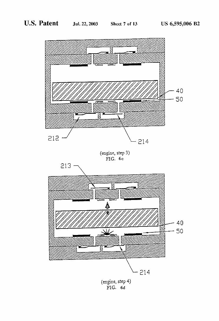
(engine, step 3) FIG. 6c
40 50
40 50
(engine, step 4) FIG. 6d
U S . Patent Jul. 22,2003 Sheet 8 of 13 US 6,595,006 B2
I
ressure
Entropy
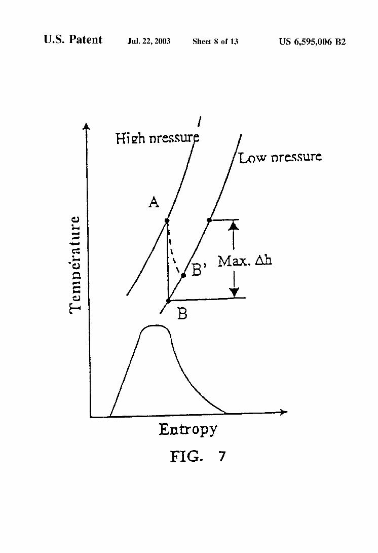
FIG- 7
U S . Patent Jul. 22,2003 Sheet 9 of 13 US 6,595,006 B2
Expander
HX-3
Cold-End
FIG. 8a
1 4
Expan
FIG, 9a
FIG. 8b
Pressure ( a h ) L 6 1.5
EL Entropy
F I G - 9c
U S . Patent Jul. 22,2003 Sheet 10 of 13 US 6,595,006 B2
E x p a n d e r n
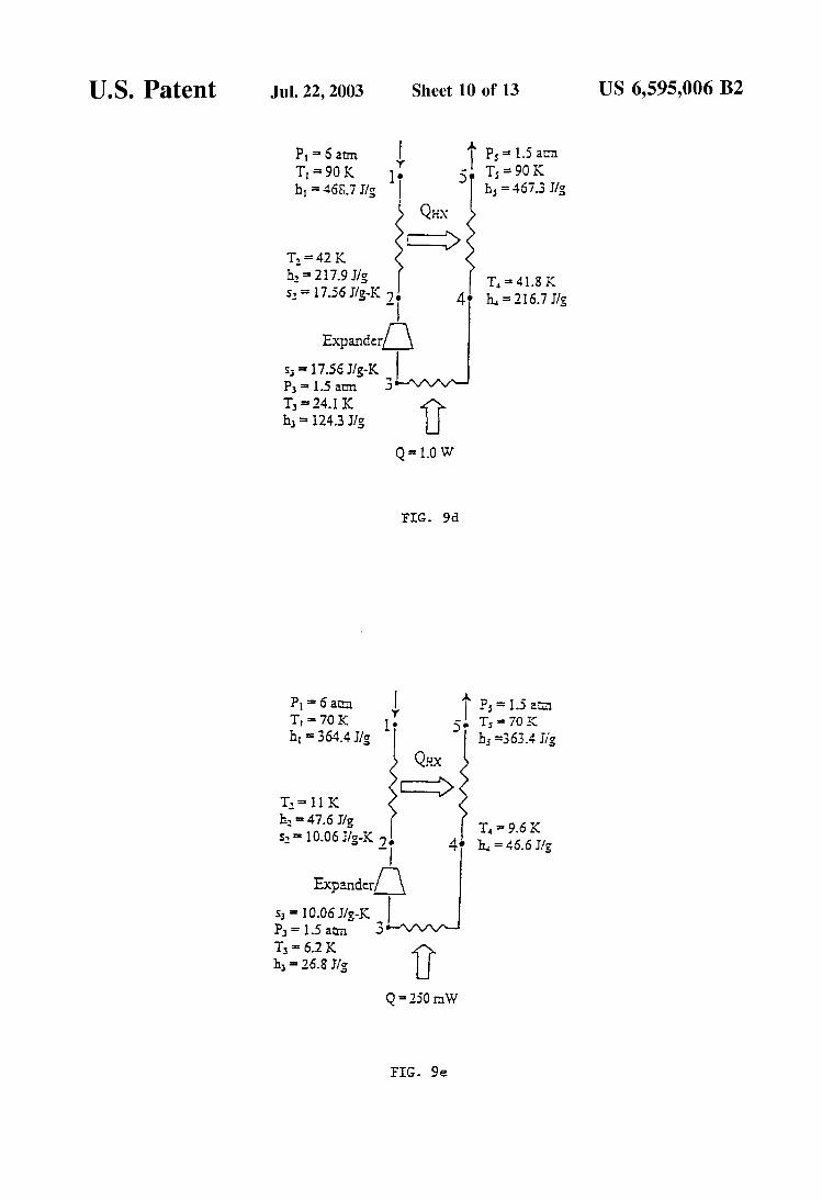
P3= ~j = 17.56 1.5 am JIS-IC 3 d U T3 ~ 2 4 . 1 K
h3 = 124.3 Jls
Q = 1.0 W
F I G . 9d
FIG. 9e
U S . Patent Jul. 22,2003 Sheet 11 of 13 US 6,595,006 B2
FIG. 10
FIG- II
U S . Patent Jul. 22,2003 Sheet 12 of 13 US 6,595,006 B2
In le t m a n i io1 d
Exhaust rnonifold
F I G - 12
U S . Patent
Inlet
Jul. 22,2003 Sheet 13 of 13
m
:-
---d
utlet manifoId
Inlet
US 6,595,006 B2
i Ll-m I u u - Valves =e6 a m =
Valve plate
Piston e Spacer e
Midpiate
Flexure
Midplate
Spacer Piston 0 . -
Valve plate
-
Outlet manifold
US 6,595,006 B2 2
most common cryogenic systems operate at only a few percent of Carnot efficiency.
Present cooling and refrigeration technologies are unable to satisfy present demands. For example, as CMOS elec-
5 tronics have approached the 0.18 pm gate size, they have begun to generate heat densities that require active cooling if these electronic devices are to operate efficiently and reliably. To date there have been many proposed solutions to the problem of cooling very dense microelectronics, but very few of these proposals provide substantial sub-ambient cooling power, and none do so efficiently.
There are also many applications for cryogenic cooling, which extend beyond the needs of conventional electronics, such as superconducting electronics and infrared imaging
15 sensors cooled to temperatures of 35 K and below. There are many applications for which superconducting electronics, operating at both high (70-35 K) and low (354 K) temperatures, provide the only feasible solution. Likewise there are many high-precision long-wavelength remote sens-
2o ing applications, which can only be realized if the sensing detector is maintained at very low temperatures. Often, however these applications have limited space available for the cryogenic system and limited power with which to drive such a system. These two requirements greatly increase the
25 cost and difficulty of realizing present cryogenic support systems.
Present cryogenic cooling technologies suffer from one or more of the following limitations: limited lifetime, high cost, large size, excessive weight, vibration, and ineffective inte-
30 gration with the objects to be cooled. Commercial and tactical cryocoolers that operate at liquid nitrogen tempera- tures cost on the order of tens of thousands of dollars, generally have lifetimes of less than two years, have limited heat lift, and do not incorporate effective vibration control.
35 Low-temperature cryocoolers, such as Gifford-McMahon cryocoolers, weigh several hundred pounds, have high vibration, and require several kilowatts of power input for a few watts of heat lift at 10 K and below. Aerospace cryo- coolers that have long lifetimes and vibration control can
40 cost over one million dollars each. These cryocoolers have high efficiency for temperatures above 50 K, however, as their operating temperature decreases, their efficiency gets much worse, and their practical minimum temperature is about 30 K. Further, all present cryocoolers require complex
45 and expensive assembly procedures that do not readily lend themselves to mass production; therefore, they are limited in their capacity to enjoy economy of scale cost reductions.
For all of these reasons, there has been a need in devel- oping miniaturized and highly efficient cryogenic systems
50 using Micro-Electro-Mechanical Systems (MEMS) tech- nologies. For example, see U.S. Pat. Nos. 5,932,940,5,941, 079, and 5,457,956. Unfortunately, applying the common principles of refrigeration and cryogenic design to systems with dimensional scales of microns and millimeters has
5s posed substantial problems. For example, U.S. Pat. No. 5,932,940 proposes a reverse Brayton cycle refrigerator, but to extract useful amounts of heat the proposed system must operate at very large rotational speeds, 300-1000 krpms. Among the many technical challenges presented in reducing
60 such a design to practice is the fact that this turbine speed requires complex load bearing assemblies; refer to K. S. Breuer et al. “Challenges for High-speed Lubrication in MEMS”. To operate properly, these bearings must be fab- ricated with such precision that present MEMS process
65 technologies are not capable of satisfying the requirements. U.S. Pat. Nos. 5,457,956 and 5,941,079 appear to require
a material that has thermal properties outside those of known
1 MINIATURE RECIPROCATING HEAT
PUMPS AND ENGINES
CROSS-REFERENCE TO RELATED APPLICATIONS
This application claims priority to U.S. provisional appli- cation serial No. 601268,523, filed Feb. 13, 2001, and U.S. provisional application serial No. 601331,883, filed Nov. 20, 2001 which are both hereby incorporated by reference in their entirety to the extent not inconsistent herewith.
STATEMENT REGARDING FEDERALLY SPONSORED RESEARCH OR DEVELOPMENT
Portions of this invention were made with U.S. Govern- ment support under Air Force Contract Number F29801-00- C-0188 awarded by the Air Force and this invention was made with Government support under contract NAS2-01042 awarded by NASA. The Government has certain rights in this invention.
BACKGROUND OF THE INVENTION
This invention relates generally to devices for cooling, generating power, compressing, pumping, and evacuating to pressure below ambient.
There are numerous references in the literature to minia- turized devices whose recent appearance is coincident with the application of microfabrication processes to the produc- tion of mechanical systems. Microfabrication processes are those typically associated with integrated circuit production, but more generally include processes capable of producing components and assemblies with micron-sized features and producing a plurality of assemblies or components simulta- neously or in “batches”. The fine dimensional tolerances of microfabrication processes means that entire classes of novel miniaturized machines can be realized. The ability to produce multiple parts simultaneously means that in many cases these novel machines may be produced efficiently and in great numbers; batching leads to economy-of-scale reduc- tion in the production costs.
The realization that many macroscopic machines can be fully miniaturized has led to a class of devices; for examples see “Silicon Micromachining”, Cambridge University Press, 1 9 9 8 a n d “ H a n d b o o k of M i c r o l i t h o g r a p h y , Micromachining, and Microfabrication”, SPIE Press, 1997, incorporated herein by reference to the extent not inconsis- tent herewith.
One way to enhance microelectronic system efficiency as well as increase reliability is to cool electronic devices to temperatures that substantially reduce power consumption/ generation. This however, implies a substantial cooling system. The large heat density produced by present genera- tion electronics is one of the main problems facing present cooling systems. Present heat densities are now exceeding 30 W/cm2. However, if these same circuits could be cooled to cryogenic temperatures, they could operate at higher frequencies, with reduced power, more reliably, and at lower voltages as indicated in the references by E. Simoen and P. Ghazavi (citations below).
Three of the most important considerations facing any novel active cooling technology are cost of implementation, reliability, and efficiency. If the cooling device is prohibi- tively expensive and/or unreliable or if the cooling device uses substantially more power than is saved, many of the benefits derived from cooling vanish. Efficiency is espe- cially important when cryogenic cooling is considered, since
US 6,595,006 B2 3 4
materials. In addition, the frequency at which these proposed these two pumps are involved almost exclusively with MEMS compressors must operate to produce a useful cool- micrometering applications and are not suited for more ing effect is too high for an efficient resonant system. robust general purpose pumping applications. U.S. Pat. No.
Chemical charge storage batteries have provided the 6,106,245 discloses a diaphragm pump, with an electrostati- majority of the portable energy sources for powering por- 5 cally actuated polymer diaphragm. TO move significant table electronics. Such batteries, however, are limited in amounts of fluids at useful pressures, a number of these both power density and lifetime, particularly when it is pumps would have to be ganged in a series-parallel con- desired that the power source be reusable. For these reasons figuration. Further, the continuously flexing diaphragm and since the power demands of portable electronic devices introduces a serious reliability issue, especially considering have been steadily increasing, chemical batteries have that the diaphragm is fashioned from a polymer and in some become increasingly inadequate. By comparison to configurations is bi-stable exhibiting a “snapping” behavior. batteries, heat engines, such as internal combustion engines, U.S. Pat. No. 6,019,882 discloses an electro-osmotic pump. generate large amounts of power, but are typically massive, The electro-osmotic process is observed when an making them incompatible with portable applications. One electrolyte, a liquid containing solvated ions, comes into of the reasons that heat engines produce large amounts of 15 contact with a solid under the influence of an electric field. power results from the large energy density of liquid fuels, Because an electrolyte forms a charged layer at the interface much larger per unit mass than any known charge storage between the solid and the liquid, an electric field can device. Thus, if liquid fuels or pressurized gases can be used produce a net drift of the charged species, resulting in fluid to drive a miniaturized electrical power generator, the result flow at increased pressure. As disclosed in U.S. Pat. No. would be a revolution in portable energy technology which 2o 6,019,882, the electro-osmotic effect is significant for would enjoy increased operating times at higher levels of porous media and in this case, the system can generate very power consumption, reduced operating expense, higher lev- large hydraulic pressures. The drawback to this invention is els of reusability, and a more environmentally benign opera- the fact that this effect is only observed for special fluids tional effect. containing ionic species; thus to pump any fluid in which
Of the proposed solutions to portable power generation, 25 ionic species are not present requires a complex secondary two examples are found in U.S. Pat. Nos. 5,932,940 and pumping system. In fact pumping vaporized fluids, as pro- 6,109,222. U.S. Pat. No. 5,932,940 proposes a microscale posed in U S . Pat. No. 6,019,882, will almost certainly gas turbine operating at very large rotational speeds, which involve the fabrication of a diaphragm-based pump, with can collect the energy released during the gas-phase corn- some of the same reliability limitations affecting U.S. Pat. bustion of a fuel and oxidizer, and convert it into electrical 30 No. 6,106,245. The diaphragm-based design will be required energy. The miniaturization of the gas turbine provides to maintain isolation between the electrolyte and the fluid many technical advantages. However, the very large rota- being pumped. tional speed required to produce useful effects has presented Unlike the preceding patents which all use some form of severe difficulties in producing an operating device, chief electric actuation to realize a miniaturized pump, U.S. Pat. among them the fabrication of high precision gas-bearings. 35 No. 5,788,468 deals with a magnetically actuated pump. The tolerance requirements of these bearings have made And while magnetic actuation is a useful means for reducing implementation very difficult and will quite dramatically the operational voltage, this invention has several limita- increase production costs; refer to K. S. Breuer et al. tions. For example, the disclosed invention, and more impor- “Challenges for High-speed Lubrication in MEMS’. tantly the technique for its manufacture, describes devices
On the other hand, U.S. Pat. No. 6,109,222 proposes a 40 whose actuation vectors are parallel to the substrate upon micro/meso-scale reciprocating piston that oscillates which the devices are fabricated, severely limiting the between combustion cylinders. In this case, the energy volume of fluid that may be moved per stroke. Further, since released during combustion of the gas-phase products is generating large pressures is proportional to the ability to collected either mechanically from gas jets or via magnetic fabricate electromagnetic coils with large Ampere-turns, it is commutation. Again, it is not clear an operating device can 45 not clear that any of the proposed embodiments could be prepared with the needed efficiency or reliability. In fact functionally enjoy the benefits of batch fabrication, operate all other presently proposed miniaturized power-generation at high electrical power efficiencies, or have extended opera- technologies seem to have practical limitations to their tional lifetimes. usefulness including limited energy generation capabilities, All of the presently proposed miniaturized pumps suffer questionable reliability, severe operational inefficiencies, 50 from one of the following deficiencies: limited mass flow complicated and expensive manufacture, and the require- capabilities (plimin), difficult and expensive fabrication ment for tolerances which presently exceed capab es of processes, excessive valve leakage, inefficient and unreli- microfabrication processes. able operation, and very low pressure heads (less than an
There are numerous potential applications for miniatur- atmosphere). ized pumps for moving fluid volumes and compressors for ss Finally, a miniaturized vacuum system is essential to any increasing gas pressures. Such pumps (or compressors for number of novel miniaturized systems presently under gases) can be used to control scaled-down chemical development. For example, many forms of chemical and processes, to meter fluids, circulate compressed fluids for scientific testing cannot be performed under conditions other temperature control processes, dispense medicines, and than at reduced pressures. Recently there has been a great actuate miniaturized hydraulic systems. Many MEMS 60 deal of interest in the fabrication of miniaturized sensing and pumps have been proposed; representative examples can be analysis devices many of which would benefit from a highly found in U.S. Pat. Nos. 5,932,940, 6,109,889, 5,336,062, portable, compact, low-power, and efficient method for 6,106,245,6,019,882, and 5,788,468. All of these inventions evacuating a fixed volume and/or maintaining pressures have limitations; U.S. Pat. No. 5,932,940 has the same reduced below ambient hereafter referred to as a vacuum. An limitations detailed previously. U.S. Pat. Nos. 6,109,889 and 65 example of such applications is miniaturized mass- 5,336,062 are suited to very small applications when neither spectrometry; e.g., U.S. Pat. No. 6,157,029. Likewise, a a large pressure head nor a significant volume is required; large number of electronic devices, such as field emission
US 6,595,006 B2 5
tips and miniaturized vacuum tubes, require the maintenance of vacuum to operate; e.g., U.S. Pat. No. 5,763,998. Due to fabrication limitations, the sealed vacuum enclosures of the electronic systems often have significant leak rates. The long-term consequence of these leaks is of course degraded performance. Such systems could clearly benefit from an inexpensive, highly compact vacuum system that could be incorporated into the system architecture and periodically refresh the vacuum of the enclosed devices. Several minia- turized vacuum pumps have been proposed; e.g., U.S. Pat. No. 5,871,336. The invention described in U.S. Pat. No. 5,871,336 can only evacuate very small volumes and under very small flows of higher-pressure gas.
There is a need in the art for improved cooling systems, power generation devices, pumping systems, and vacuum systems.
SUMMARY OF THE INVENTION
The present invention provides devices and methods for cooling, generating power, pumping fluidsicompressing gases, and producing a vacuum. These devices and methods are capable of being miniaturized, use a reciprocating piston, are highly efficient, and are capable of being mass-produced using the broad class of microfabrication techniques men- tioned above and informally known as Micro-Electro- Mechanical Systems (MEMS) processes or conventional processes.
In one embodiment, the present invention is a highly compact, modular, low-cost, lightweight, miniaturized heat pumplheat engine. This heat pumplheat engine can be used to produce significant amounts of cooling down to cryogenic temperatures, to generate significant amounts of power, to pump substantial amounts of fluids, to compress gases, and to produce a vacuum.
More specifically, there is provided a fluid expander comprising: a housing defining an enclosed work space and having a working fluid, said housing comprising: a first end forming a first plate of a capacitor; a piston slidably disposed in the housing for reciprocating motion to define a variable volume within said housing, said piston having a first side forming a second plate of a capacitor, said second plate in electrostatic or magnetic connection with said first plate; and a control circuit linked to said piston and said first end which controls the strength of the electrostatic or magnetic force between the plates of the capacitor.
The description above describes a single-stage device. It should be recognized that any of the devices described herein may operate as single-stage (single-acting) devices or double-stage (double-acting) devices. For example, in the expander described above, a double-acting device is formed by adding a second end to the housing. In the double-acting device, the piston is slidably disposed in the housing between the first end and the second end for reciprocating motion to define a variable volume within the housing. In addition to the first side of the piston which forms a first capacitor with the first end, in double-acting devices, the piston has a second side in electrostatic connection with the second end of the housing and forms a second capacitor. Also, the control circuit linked to the piston controls the strength of the electrostatic or magnetic force between the first end and the piston and the second end and the piston.
Also provided are methods of using the devices described herein. One exemplary method of use is a method of expanding a gas, the method comprising: applying a clamp- ing voltage between a piston slidably disposed in a housing and a first end of said housing, wherein said piston moves
6 toward said first end but does not contact said first end; allowing a working fluid (pressurized gas, for example) to enter the space between said first end of said housing and said piston; releasing the clamping voltage between said
5 piston and said first end, whereby said piston moves away from said first end and said working fluid is expanded. The expansions described herein are isentropic (i.e., constant entropy). It is understood that a completely isentropic pro- cess is impossible because of various losses described herein and known to the art. When the term “isentropic” is used herein, it is to be understood that processes that are physi- cally obtainable are referred to, including those processes where the losses, which cause an isentropic process to move from the ideal, are minimized to the extent possible and
All methods described herein may be single-acting or double acting, where the device configuration is altered as discussed above. In double-acting devices, while the piston is energized with respect to the first end of the housing and
2o an associated change in thermodynamic state is occurring in the first end, the mechanical motion of the second end of the housing is preparing the second end for such action in a complementary way. In a double-acting expander, the method comprises: applying a clamping voltage between a
25 piston slidably disposed in a housing and a first end of the housing, the housing defining an enclosed work space and the housing comprising a first end having at least one inlet and at least one outlet and a second end having at least one inlet and at least one outlet, wherein the piston moves
30 toward the first end but does not contact the first end; allowing a working fluid to enter the space between the first end of said housing and the piston; releasing the clamping voltage between the piston and the first end, wherein the working fluid is isentropically expanded and the piston
35 moves away from the first end and toward the second end; applying a clamping voltage between the piston and the second end of the housing, wherein the piston moves toward the second end but does not contact the second end; allowing a working fluid to enter the space between the second end of
40 the housing and the piston; releasing the clamping voltage between the piston and the second end, wherein the working fluid is isentropically expanded and the piston moves away from the second end and toward the first end. The cycle can be repeated as desired.
As used herein, energizing or activating means a suitable force is applied to a component (piston, for example), or section (capacitor formed between the piston and first end, for example) to produce the desired effect. As described herein, the piston may be energized electrically or
Also provided is a method of generating power compris- ing: placing a combustible substance in the first end of a housing having a first end and a second end and a piston slidably disposed in said housing for reciprocating motion to
ss define a variable volume within the housing, the piston having a first side in electrostatic or magnetic connection with the first end of said housing and forming a first capacitor and a second side in electrostatic or magnetic connection with the second end of the housing and forming
60 a second capacitor; energizing the piston by applying a force to the piston so that the piston is moved toward the first end; igniting the combustible substance, thereby increasing the temperature and pressure in the first end; reducing the force on the piston allowing the combustible substance to expand
65 against the energized capacitors formed by the piston and the housing, thereby generating power. The power may be harnessed or transferred by any means known in the art.
15 practical.
45
50 magnetically, or using a combination of both methods.
US 6,595,006 B2 7 8
Also provided is another method of generating power electrostatic or magnetic connection with said first end of comprising: applying a clamping voltage between the first said housing and forming a first capacitor, said piston having end of a housing and a piston slidably disposed in the a second side in electrostatic connection with said second housing and in electrical or magnetic connection with the end of said housing and forming a second capacitor; and first end of the housing; admitting heated gas or fluid into the means for providing electrical or magnetic control to said first end of a housing; releasing the clamping voltage on the device, said compressor in fluid or gas connection with said Piston; allowing the Piston to expand away from the first cooler; a heat exchanger in fluid or gas connection with said end, thereby generating power. This heated gas may be compressor and said cooler, whereby in operation, cooling is supplied by heat generated from any Source including the provided to the desired level. Also provided is a means type of heat generated from electronics Or by combustion 10 whereby the cooler may be an expander, which uses the products. expansion method, provided herein.
Also provided is a cooling system comprising: a pre- comprising: placing a compressible substance in the first end cooler; a compressor in fluid connection with said precooler; of a housing having a first end having at least one inlet and a first heat exchanger in fluid connection with said com- at least one outlet, and a second end having at least one inlet 1~ pressor; an expander in fluid or gas connection with said first
housing between the first end and the second end for at least one inlet and at least one outlet, a second end having reciprocating motion to define a variable volume within the at least one inlet and at least one outlet, a piston slidably housing, the piston having a first side in electrostatic or disposed in the housing between said first end and said magnetic connection with the first end of the housing and 2o second end for reciprocating motion to define a variable forming a first capacitor, the piston having a second side in volume within said housing, said piston having a first side in electrostatic connection with the second end of the housing electrostatic or magnetic connection with said first end of
5
provided is a method Of pumping a substance
and at least One Outlet, a piston slidably disposed in the heat exchanger, said expander comprising a first end having
and forming a second capacitor; energizing the piston by said housing and forming a first capacitor, said piston having a second side in electrostatic connection with said second
toward the first end, whereby the temperature and pressure 25 end of said housing and forming a second capacitor; a of the compressible substance are increased; removing the second heat exchanger in fluid or gas connection with said
a force to the piston so that the piston
compressible substance from the first end of the housing. A expander; control electronics which are in electrical con- for is provided by placing a nection with said expander and said compressor, Also pro-
vided is a means whereby said precooler may be an expander compressible substance in the second end of the housing, energizing the piston by applying a force to the piston so that 30 using the method of expansion described herein, the piston moves toward the second end, whereby the Also provided is a method for mechanical voltageienergy temperature and pressure of the compressible substance are conversion comprising: applying a force between a first end increased; removing the compressible substance from the of a housing and a piston in a housing having a first end second end of the housing. having at least one inlet and at least one outlet, a second end
provided is a method Of reducing the pressure in a 35 having at least one inlet and at least one outlet, and a piston vessel in gas or fluid connection with a housing comprising: slidably disposed in the housing between said first end and simultaneously minimizing the volume of the first end of a said second end for reciprocating motion to define a variable housing having a first end and a second end, separated by a volume within said housing, said piston having a first side in piston slidably disposed in the housing between the first end electrostatic or magnetic connection with said first end of and the second end for reciprocating motion to define a 40 said housing and forming a first capacitor, said piston having variable volume within the housing, the piston having a first a second side in electrostatic connection with said second side in electrostatic or magnetic connection with the first end end of said housing and forming a second capacitor; opening
side in electrostatic or magnetic connection with the second through said inlet; reducing the force between said first end end of the housing and forming a second capacitor; when the 4s and said piston so that said piston is able to move; closing second end has the volume maximized, thereby reducing the pressure in the second Gas at a higher pressure than that present in the second end is then admitted from the vessel into the second end raising the pressure of the second end and incrementally decreasing the pressure of the vessel. 50
energizing the piston so that it moves toward the second end reducing the volume of the second end simultaneously increasing the volume of the first end reducing the pressure of the gas in the first end, thereby providing a means for 5s
minimized and the volume of the first end has been maxi- mized.
Also provided are ways of using the devices described herein in a cooling system, for example comprising: a cooler 60 in thermal connection with an object to be cooled; a com- pressor comprising a housing having a first end having at least one inlet and at least one outlet, a second end having at least one inlet and at least one outlet; a piston slidably disposed in the housing between said first end and said 65 second end for reciprocating motion to define a variable volume within said housing, said piston having a first side in
Of the housing and forming a first capacitor and a second said inlet to said first end; inserting gas into said first end
the inlet valve to said first end, whereby the gas in said first end increasing the electrical potential between the first end and the piston,
Also provided is a means whereby electrostatic forces
self-aligned structure can be formed as described herein and known to one of ordinary skill in the art. The invention may be used as a liquefaction system for various gases, as will be evident from the disclosure. The devices may be operated
Other uses for the devices described herein are included in the invention and will be readily apparent to one of Ordinary
BRIEF DESCRIPTION OF THE DRAWINGS
The gas in the second end is expelled through an outlet by may be to the piston to the This
double action when the volume of the second end has been continuously by the steps, as known in the art.
in the art.
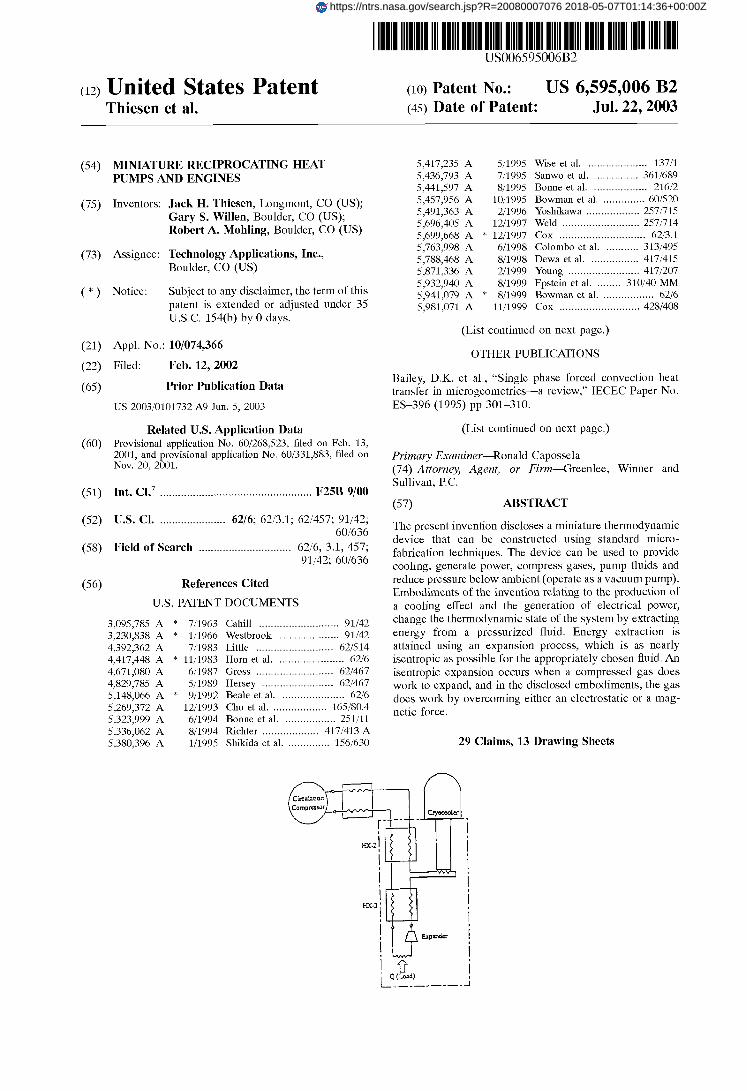
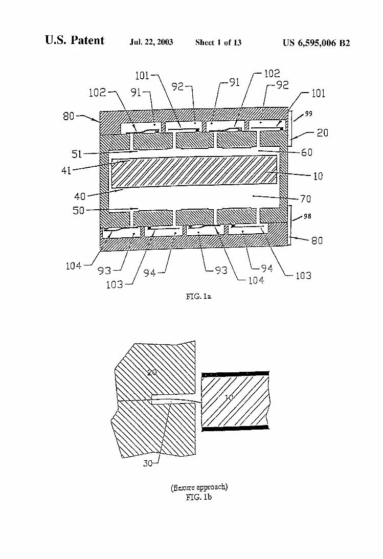
FIG. 1 A is a sectional view showing the heat pumpiheat engine
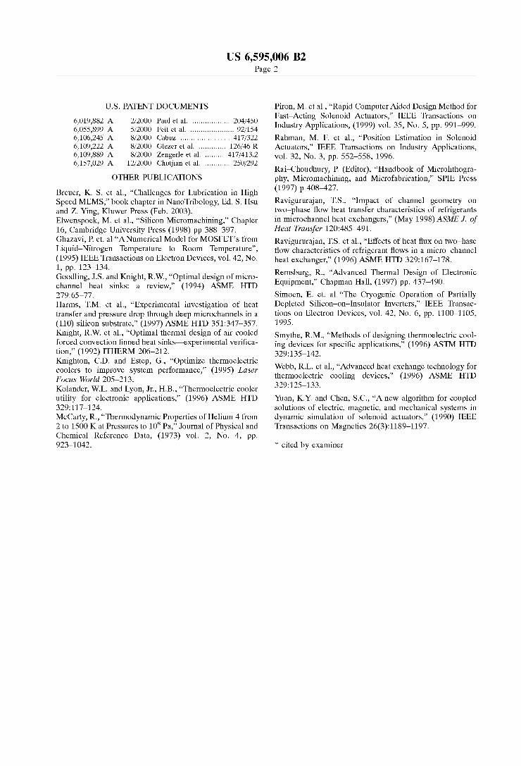
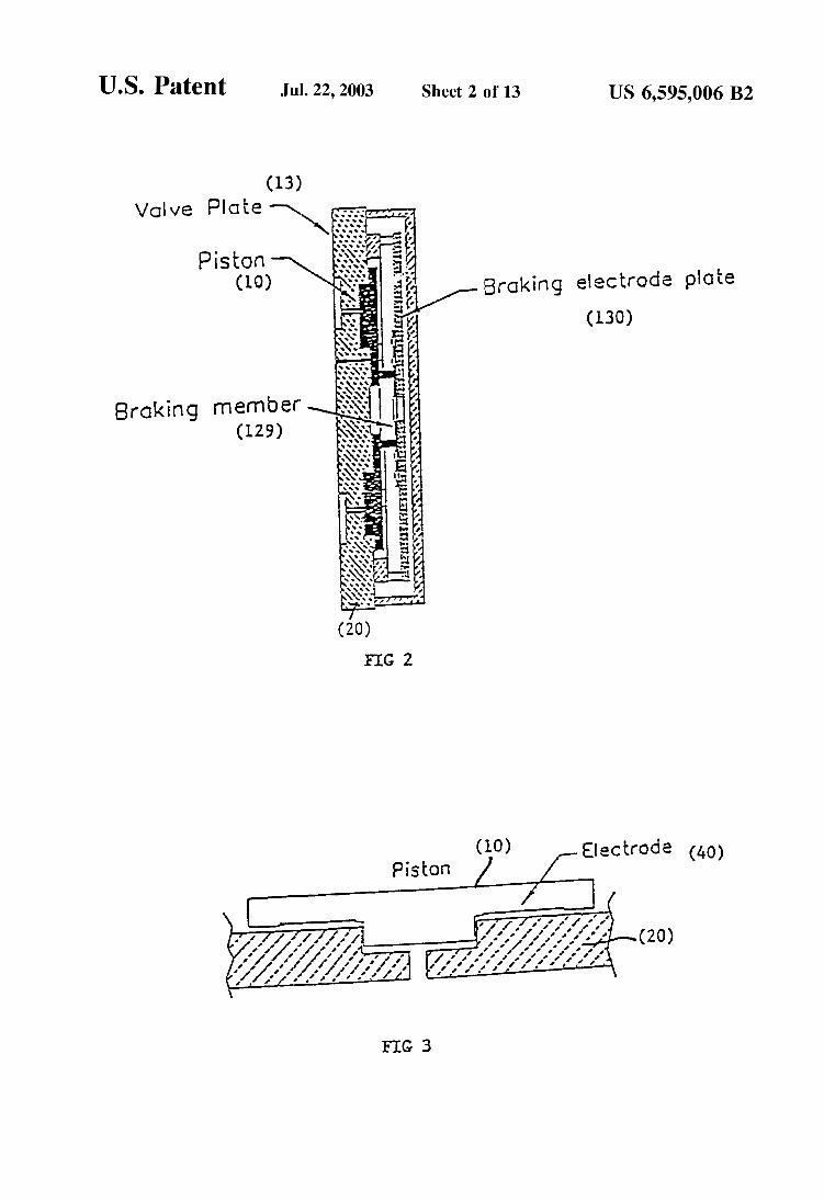
lB shows the flexure approach shows a sing1e acting device.
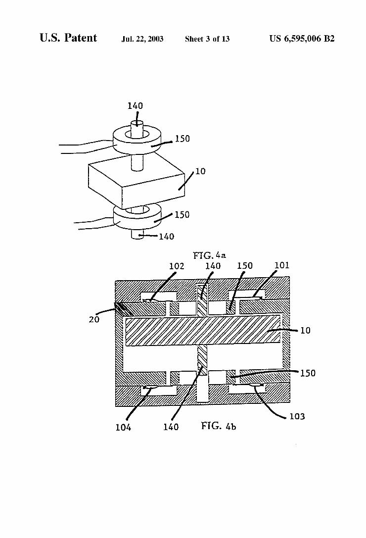
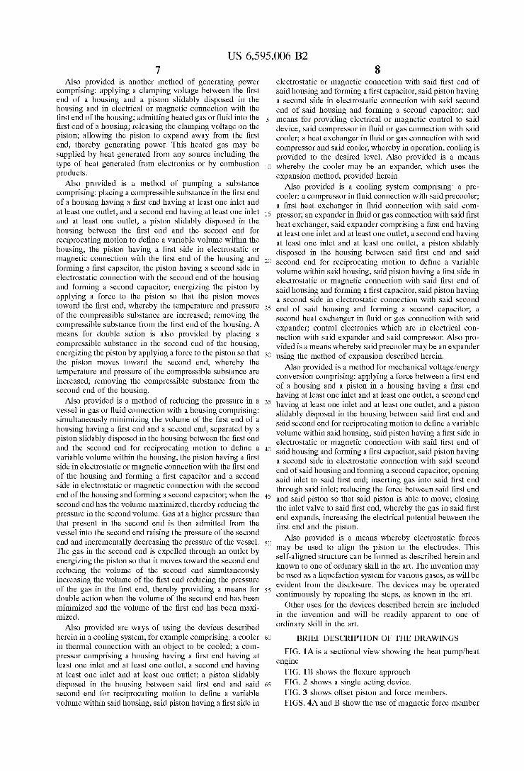
FIG. 3 shows offset piston and force members. FIGS. 4A and B show the use of magnetic force member
US 6,595,006 B2 9
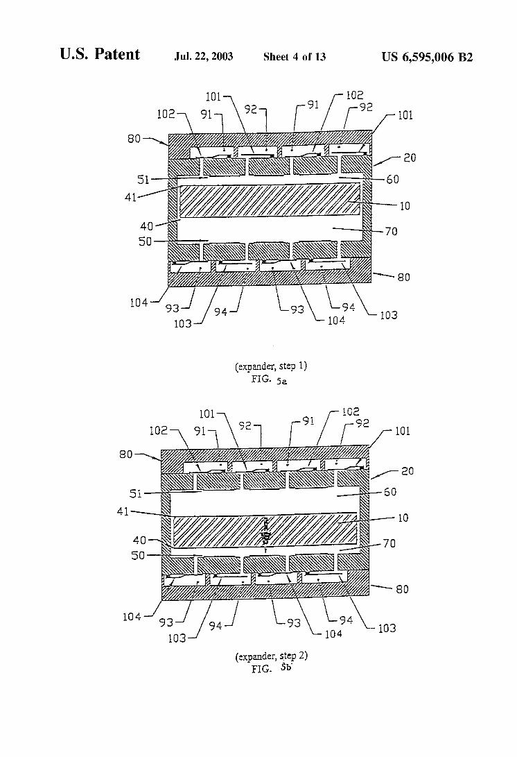
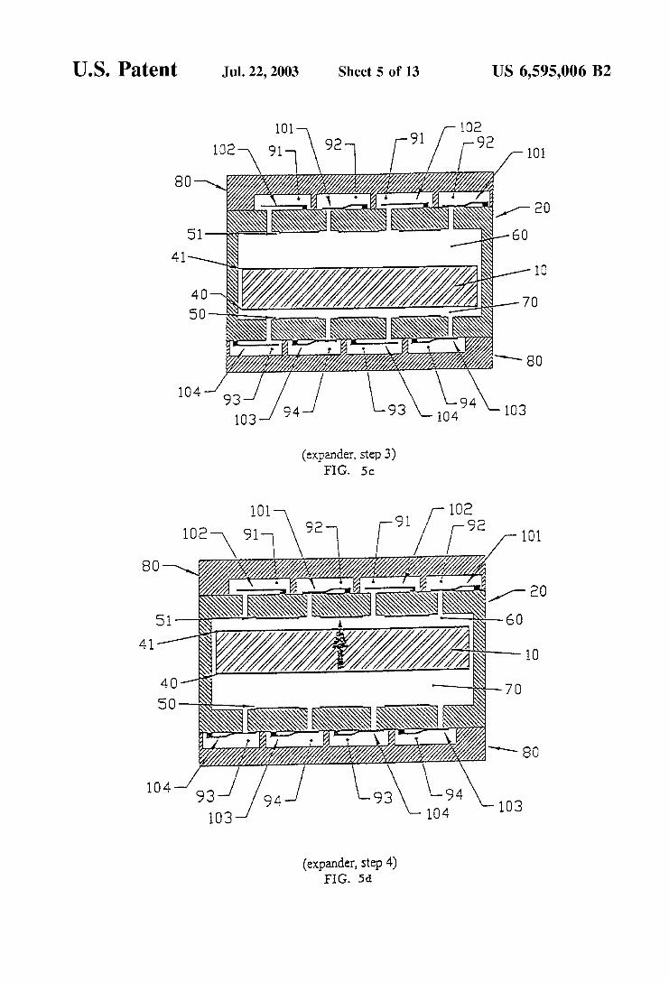
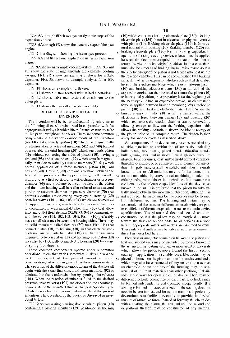
FIGS. 5A through 5D shows system dynamic steps of the
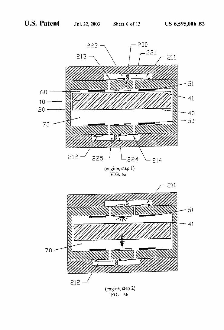
FIGS. 6Athrough 6D shows the dynamic steps of the heat
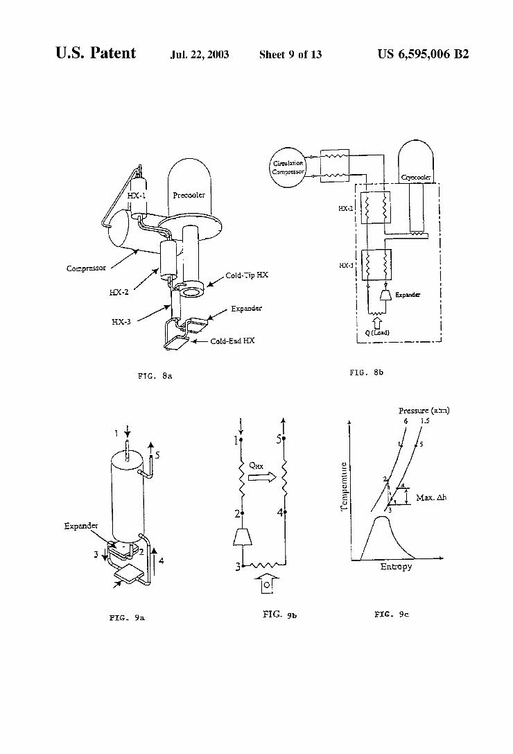
FIG. 7 is a diagram showing the isentropic process. FIGS. SA and 8B are one application using an expansion
engine. FIG. 9Ashows an example cooling system; FIGS. 9B and
9C show the state change through the example cooling system; FIG. 9D shows an example analysis for a 35K expander; FIG. 9E shows an example analysis for a 10K expander.
expansion engine.
engine.
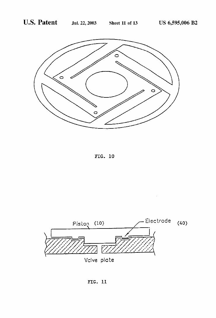
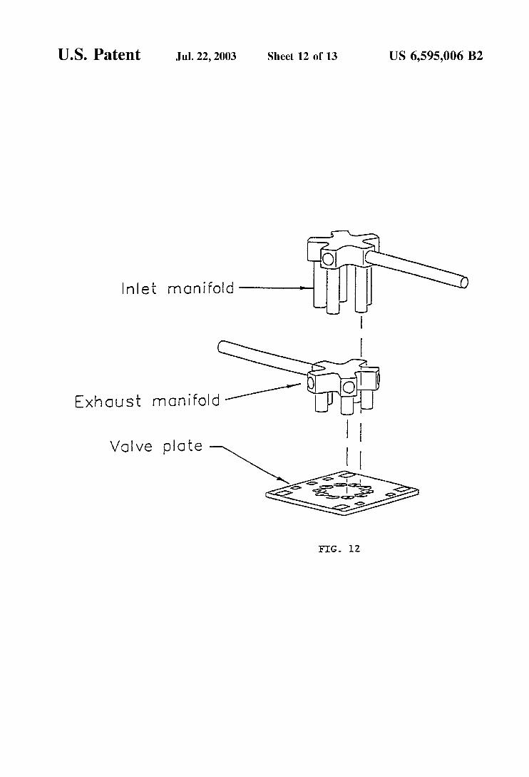
FIG. 10 shows an example of a flexure. FIG. 11 shows a piston formed with raised electrodes. FIG. 12 shows valve manifolds and attachment to the
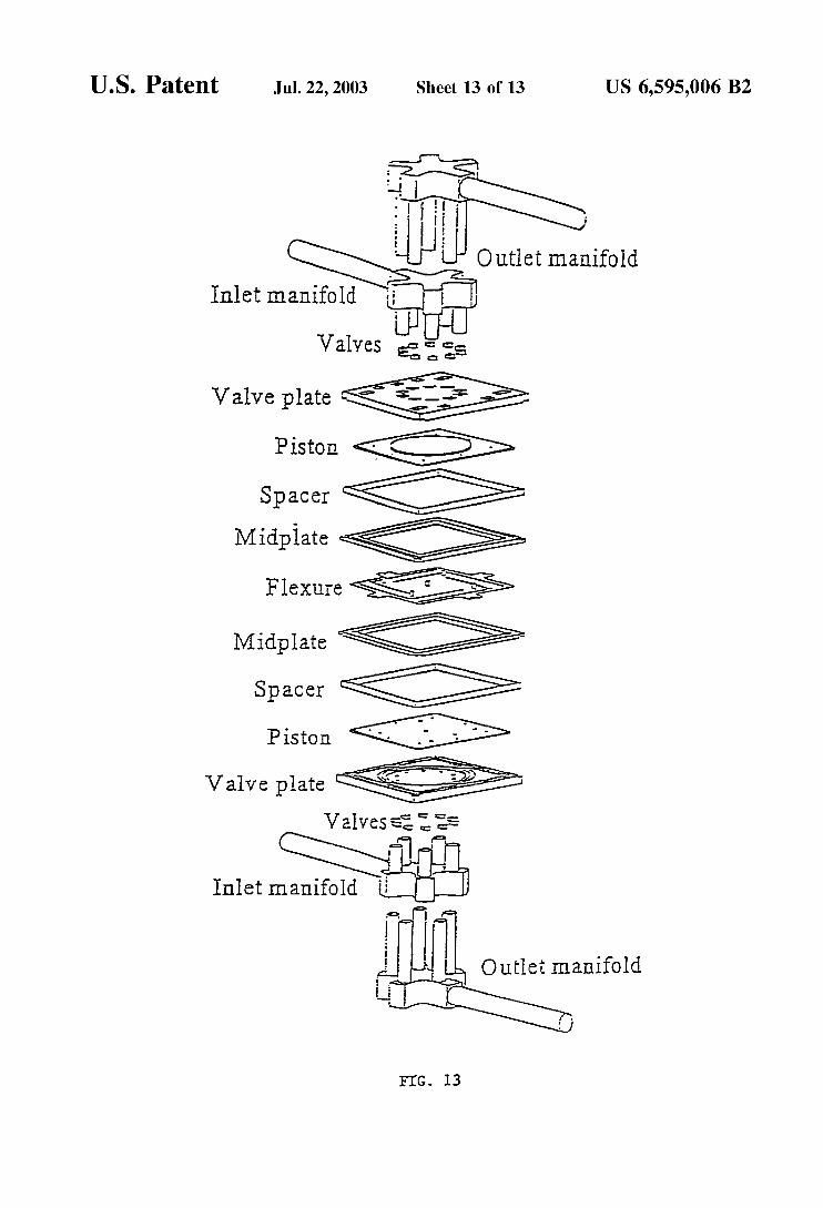
FIG. 13 shows the overall expander assembly.
DETAILED DESCRIPTION OF THE INVENTION
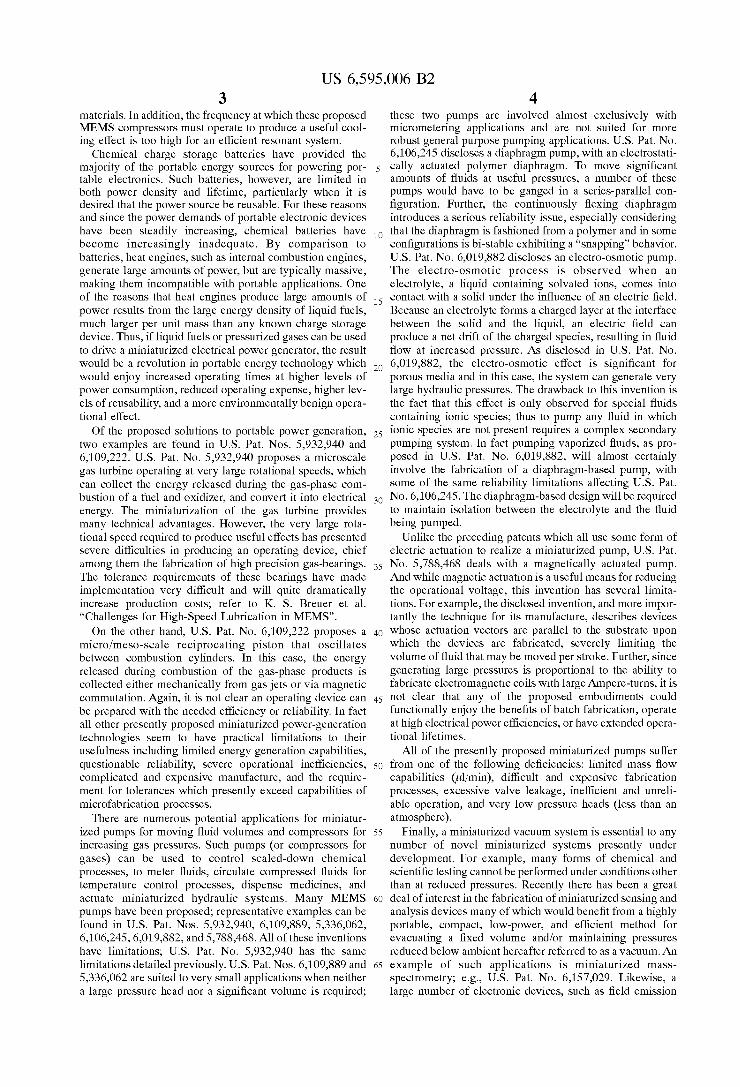
The invention will be better understood by reference to the following discussion when read in conjunction with the appropriate drawings in which like reference characters refer to like parts throughout the views. There are some common components in the various embodiments of the invention (see FIG. lA), namely: piston (10) which has magnetically or electrostatically actuated members (41) and (40) formed of a suitable material housing (20) which surrounds piston (10) without contacting the sides of piston (lo), having a first end (98) and a second end (99) which contain magneti- cally or an electrostatically actuated members (50,51) which permit application of a force between piston (10) and housing (20). Housing (20) contains a volume between the face of the piston and the upper housing wall hereafter referred to as a first portion or reaction chamber or pressure chamber (60) and a volume between the face of the piston and the lower housing wall hereafter referred to as a second portion or reaction chamber or pressure chamber (70) that permits a double action during every cycle. Housing (20) contains valves (101, 102, 103, 104) which are formed on the upper or lower ends, which allow the pressure chambers to communicate with manifold structures (80) that allow inlet and outlet fluid streams (91,92,93, 94) to communicate with the valves (101, 102,103,104). Piston (10) preferably has a small clearance between the housing sides. There may be solid members called flexures (30) (see FIG. 1B) that connect piston (10) to housing (20) so that electrical con- nections can be made to piston (10) and to prevent mis- alignment between piston (10) and housing (20). Piston (10) may also be electrically connected to housing (20) by a wire or spring (not shown).
These common components operate under a common operational cycle that varies somewhat in detail given the particular aspect of the present invention under consideration, but which in general has three common steps. The operation of the different embodiments of the devices all begin with the same first step; fluid from manifold (92) is admitted into the reaction chamber by opening inlet valve(s) (101). When the reaction chamber is filled to the desired pressure, inlet valve(s) (101) are closed and the thermody- namic state of the admitted fluid is changed. Specific cycle details then define the various embodiments of the present invention. The operation of the device is discussed in more detail below.
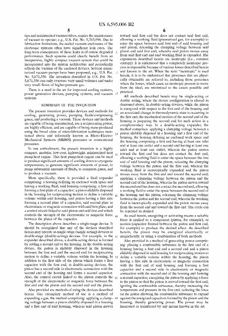
FIG. 2 shows a single-acting device where piston (10) containing a braking member (129) positioned in housing
valve plate.
10 (20) which contains a braking electrode plate (130). Braking electrode plate (130) is not in electrical or physical contact with piston (10). Braking electrode plate (130) is in struc- tural contact with housing (20). Braking member (120) and
5 braking electrode plate (130) form a braking capacitor. In operation of a single acting device, a force must be applied between the electrodes comprising the reaction chamber to return the piston to its original position. In this case there must also be a means of braking the returning piston so that the kinetic energy of the piston is not turned into heat within the reaction chamber. This can be accomplished by a braking capacitor. After an expansion stroke such as that described herein, the electrostatic force which exists between piston (10) and braking electrode plate (130) at the end of the
1~ expansion stroke can then be used to return the piston (10) to its original position, thus preparing it for the beginning of the next cycle. After an expansion stroke, an electrostatic force is applied between braking member (129) attached to piston (10) and braking electrode plate (130). When the
2o kinetic energy of piston (10) is at the desired value, the electrostatic force between piston (10) and housing (20) which acts across the reaction chamber can be removed by allowing charge to flow out the braking capacitor-this allows the braking electrode to absorb the kinetic energy of
25 the piston prior to its complete return. The device is then ready for another cycle as described above.
All components of the devices may be constructed of any suitable materials or combination of materials, including bulk metals, cast metals, plated metals, thin-film metals,
30 bulk glasses, cast and/or mold formed glasses, thin-film glasses, bulk ceramics, cast and/or mold formed ceramics, thin-film ceramics, bulk polymers, mold formed polymers, thin film polymers, crystalline solids, and other materials known in the art. All materials may be further formed into
35 components either by conventional machining or microma- chining using microfabrication techniques in a manner that conforms to the tolerance specifications of the device, as known in the art. It is preferred that the piston be substan- tially nonflexible in the movement direction, although it is
40 not required. The piston may be one piece, or may be formed from different sections. The housing and piston may be constructed of the same or different materials with care paid to coefficient of thermal expansion issues to maintain device specifications. The piston and first and second ends are
45 constructed so that the piston may be energized to move toward the first and second ends. In all devices described herein, appropriate inlets and outlets are assumed to exist. These inlets and outlets may be valve structures as known in the art or described herein.
Electrical or magnetic connection between the piston and first and second ends may be provided by means known in the art, including coating with one or more suitable materials which allows the piston to move toward the first or second ends upon application of a suitable force. Electrodes may be
ss placed or formed on the piston and the first and second ends, which may also be constructed of any material that acts as an electrode. Some portions of the housing may be con- structed of different materials than other portions, if desir- able or necessary for operation of the device. There may be
60 different electrode geometries on each part. Electrodes may be formed independently and operated independently. If a coating is formed or placed on a section, the coating does not need to be continuous, and for certain methods is preferably discontinuous to facilitate assembly or provide the desired
65 amount of attractive force. Instead of forming the electrodes with a coating, the piston, the first end and the second end or portions thereof, may be constructed of any material
SO
US 6,595,006 B2 11 12
capable of being electrostatically energized. Metals or by the specific application. A linear electromagnetic motor ceramics, which have high magnetic susceptibility, may be may also be used where the gas is allowed to do work by used in the case of magnetic actuation, as known in the art. moving a suitable magnetic member against the magnetic Activation of the piston toward the first or second ends may force established with the electromagnetic member is ener- be provided in a number of ways, for gized. Other means of magnetic actuation may also be used suitable electrical or magnetic inputs, as known in the art, A without substantially changing the intent of this disclosure.
control between the piston and said first and second ends. 4B. "lustrate One instance Of a possible method for using a magnetic field, where posts or piston
size to operators (140) on piston (10) are surrounded by magneti- provide the desired amount of cooling over the desired area, 10 cally activated members (150) for example, magnetic as known in the art. The device can provide cooling from motors, FIG, 4A shows piston (10) having 2 posts (140) room temperature to the liquefaction temperature of the surrounded by magnetically activated members (150). The working fluid selected, for example around 4.2 K for the magnetically operated piston appears in the device in the case of helium. The device may be used in series or parallel, configuration shown in FIG. 4B, where posts (140) attached as known in the art, to provide additional cooling power 15 to piston (10) and surrounded by magnetically activated and/or a more efficient cooling effect. members (150) are positioned in housing (20) which con-
Hybrid devices are also provided that use both electrical valves (101, 102, 103, 104) as described herein. and magnetic actuation in the same embodiment. In addition Cooler to embodiments of the invention having a piston and a first For the embodiment of the invention, which operates as and second end, a piston may have distributed reaction 20 an expansion engine used for cooling, the change in ther- chambers, with more than one chamber on each side of the modynamic state occurs by allowing a gas to do work piston. These chambers may be connected in ways known in through expansion by moving the Piston against a force. BY the art and described herein. doing work during the expansion the gas not only has an
increased in volume but has an associated decrease in Although the piston is shown as having parallel sides in 2s temperature and pressure. The force members may either
and the housing, or may apply both electrostatic and mag- netic forces. 3 shows electrodes (40) recessed in piston (10).
Conceptually, the expander operates by creating an elec- the Claude Or Brayton cycles as known in the art, to Provide 30 trostatic force or magnetic force between two electrodes and the desired thermodynamic change in the working fluid. allowing pressurized gas to separate the electrodes. Since
The system described may provide cooling at a variety of work is the product of force and distance, the gas does work different levels, such as 250 K or below, 70 K or below, 45 against the electrostatic force by separating the electrodes; K or below, 35 K or below or 10 K or below and all this work is eventually dissipated as heat in a load resistor. intermediate values and ranges therein, depending on the 35 By doing work, the entropy of the gas is reduced, and the design parameters chosen and the working fluid or fluids work provides an efficient means to reduce gas temperature. used. This cooling system does not need to contain any The expanded low-temperature gas is expelled during the Joule-Thomson valves (valves used for liquefaction of next expansion stroke since the designed expander is gases, where gases under pressure expand and are adiabati- double-acting. The expelled gas then moves through the cally cooled). If desired, a Joule-Thomson valve may be 40 system as described above and provides useful cooling to the incorporated to liquefy the working fluid once it is cooled applied heat load. If the expansion process is nearly revers- below its inversion temperature, as known in the art. ible and if the time it takes for the expansion to be completed
&Iy working fluid that provides the desired cooling may is short compared to the time it takes for the gas to accept be used in the invention. One preferred working fluid is heat from the outside world, then the process will be nearly helium. The selected working fluid depends upon the cool- 45 adiabatic and the overall expansion process may be consid-
application. Selection of working fluid is well within the device may also be driven by magnetically activated mem- skill of one of ordinary skill in the art, using the parameters bers in an analogous manner to the electrostatically activated discussed herein. In some cases, multiple stages may be embodiments described in detail herein. connected in series to achieve higher vacuum ratios between 50 In the design of the expansion engine, as in all expansion the inlet and outlet gas streams or higher compression ratios engines, the expanding gas will do work and in so doing lose between the inlet and outlet streams. Multiple stages con- energy, reducing both the pressure and the temperature. The nected in parallel achieve higher mass flow rates. Also design does this work, both by expelling gas from the included in the systems described is electrical circuitry to backside of the piston and by forcing current through an provide activation and control of the force members as 5s electrical load that is situated remotely from the expansion known in the art. head. The front side of the piston is defined as the side
In any case, the capacitor between the piston and the ends currently undergoing expansion, and the backside as the side may be replaced by a structure such as a rod with a high that has previously been expanded and from which gas is magnetic susceptibility attached to the piston, which is being expelled. The operation of the expansion engine can
applying 5
control circuit may be used to provide electrical or magnetic example of magnetic actuation is shown in FIGS. 4Aand 4A 8~
The device may be constructed Of any
1, the invention the configuration shown in apply an electrostatic or magnetic force between the piston 3, where piston (lo) and housing (20) are Offset.
Various thermodynamic cycles may be used, for example
ing temperature, heat lift, and other requirements of the ered as approximately isentropic. The operation of the
inserted into a coil formed in the housing. In this case, 60 be understood as the transfer of mechanical potential from passing a current through the coil around the rod energizes the gas into an electrical potential. Expressions for energy in
the coil as in a standard solenoid. In this configuration, terizations. A simple expression for electrical energy in the energy is removed from the pressurized gas as it does work capacitor in terms of plate displacement are easily derived pulling the magnetized rod out of the energized coil. This 6s by one of ordinary skill in the art. work is converted into electrical energy, which is collected, Understanding the device depends upon knowing how the stored, and distributed to various electrical loads as required energy in the capacitor changes as the plates of the capacitor
a magnetic field, which creates a force pulling the rod into the gas are well known from numerous empirical charac-
13 US 6,595,006 B2
14 are forced apart. Clearly, for increasing separation of a charged parallel plate capacitor, where one of the plates is free to move and the plates are initially separated, the potential will increase. If an expanding gas can move the plates of the piston rapidly enough, where rapid is under- stood to mean faster than the capacitor is discharging to equilibrium, then the gas does work on the capacitor result- ing in an increase in the energy stored within the capacitor If the plates are performing mechanical work, the energy stored in the capacitor is decreasing, and if mechanical work is being done by the system, the energy stored in the capacitor is increasing.
An understanding of the dynamic system and the related computational methodology is well known to one of ordi- nary skill in the art, where it is found that the total current from the device is proportional to the rate at which the plates are being forced apart and is functionally related to the rate at which energy from that gas is flowing into the circuit or the rate that potential from the gas is being transferred to potential in the capacitor, which in turn drives current flow. Also, as the capacitance decreases, the RC time constant also decreases, and the circuit discharges more rapidly. Thus, if the discharge characteristics of a circuit with a dynamically charging capacitance is allowed to dominate the circuit dynamics, the ability of the capacitor to increase the electrical potential is reduced. If the expansion stroke is of short duration compared with the time it takes for heat to be transferred from the reaction chamber, then the process may be approximated as adiabatic. If the work done by the gas on the capacitor is nearly reversible, the process will then be essentially isentropic and an approximate form of F,,, may be found from the polytropic relation between pressure and volume:
where Po is the pressure; F,,,, is force due to pressure; Vol, is the initial volume before fill; Vol(x(t)) is the volume at time t; and A is area where the exponent, 1.68, is the ratio of heat capacity at constant pressure, c,, to the heat capacity at constant volume, c,, for the fluid in question. If helium is used,
y = 2 = 1.68 C"
for temperatures above 10 K. From the force due to pressure, the force between two plates of a moving capacitor can be derived by one of ordinary skill in the art.
The gas related issues such as pressure drop in valve lines, fill times for gas flowing beneath the piston, and the dead volume related efficiency tradeoffs are known in the art and are not discussed in detail here. As derived above, at the beginning of its motion, the electrostatic force between the expander's capacitor electrodes has a quadratic dependence on the relative dielectric constant. For example, since every dielectric material has temperature dependence, temperature changes can dramatically affect the applied voltage required to produce the same force. If the dielectric constant is reduced by 5% as the temperature of the expander drops from room temperature to 70 K, the applied voltage must increase by 5% to maintain the same force. While it might seem that a few percent reduction in the initial force is not worth considering, it will be shown later that each percent reduction can result in an equivalent percent reduction in the overall efficiency of the expander.
Stiction effects arise due to molecular surface interactions and are a function of surface area. Stiction forces on the order of 140 Nicm' have been measured for MEMs-scale contacting surfaces However, a solution to the stiction effect
s problem is presented by electrodes being separated by thin lands which act as standoffs to keep the electrodes from contacting during clamping. Dielectric breakdown may affect the operation of the device. Methods to minimize the effect of dielectric breakdown are known in the art. The
i o squeeze film effect (as the expander completes its stroke, the gap separating the piston from the valve plate will become very small) may affect the operation of the device and is modeled by methods known in the art.
FIG. 5 shows the device at various stages of operation for is the case of an electrostatic force. In this case the expander
operates by creating an electrostatic force between two electrodes and allowing pressurized gas to separate the electrodes. Since work is the product of force and distance, the gas does work against the electrostatic force by sepa-
20 rating the electrodes; this work is eventually dissipated as heat in a load resistor. By doing work, the internal energy of the gas is reduced; the work provides an efficient means to reduce gas temperature. The expanded low-temperature gas is expelled during the next expansion stroke since the
zs designed expander is double-acting. The expelled gas then moves through the system as described above and provides useful cooling to the applied heat load.
Operation of the device illustrated in FIG. 5 . FIG. 5A shows the first step. With valves 102, 103 and 104 closed,
30 gas is admitted by opening inlet valveis (101) until the desired pressure is attained in reaction chamber (60). When the desired pressure in reaction chamber (60) is attained, exhaust valveis (103) are opened (FIG. 5B). Inlet valveis (101) are closed and the electrostatic force between force
3s members 41 and 51 is reduced to allow the piston to move (expanding the gas as nearly reversibly as possible) During pressurization, piston (10) is held in place by the electro- static force between force members (51) and (41). As piston (10) is moved the gas expands and energy from the gas is
40 transferred into electrostatic energy between the plates. The increased electrostatic potential drives a current through a remotely located load resistor and the expansion work is dissipated as Joule heating. As the piston moves, gas that has been expanded during the previous half-cycle is pushed out
4s through the open exhaust valves (103) and into the exhaust manifold (94). At the same time, the high-pressure gas in reaction chamber (60) is undergoing a reduction in tempera- ture and pressure. After the expansion is complete, exhaust valveis (103) are closed, piston (10) is energized toward
SO reaction chamber (70) by charging the capacitor structure formed by force members 40 and 50, the opposing inlet valveis (104) are opened, and the half-cycle is repeated (see FIG. 5C). FIG. 5D shows the device at the start of the next cycle. In this way piston (10) is double acting, expanding
ss and exhausting gas as it moves through each half-cycle. Force members (40, 41, 50 and 51) may be independently controlled such that there can be a delay of any desired length before each half-cycle is initiated. The description for the cooling application in this paragraph will hereafter be
The expander may be operated in many ways, four of which follow. The first is direct switching of the stationary filled device into a load circuit. The second is a voltage- controlled fill (VCF) whereby filling imparts a velocity to
65 the expander prior to direct switching to the load. The third is a 'hybrid' method of operation, which utilizes active voltage control of the expander's capacitive structure, again
60 referred to as Cycle I.
US 6,595,006 B2 15 16
to impart an initial velocity prior to switching of the device Cycle 11. In this embodiment the combustion chamber may into a load circuit. The last way directly switches the be external to the chamber where expansion takes place, in stationary device into a load circuit that has a load resistor this case combustion products are admitted through the inlet of sufficiently small resistance so that charge quickly leaves valves. In the same manner any source of heat that raises the the device, which in turn quickly reduces the force. After the s temperature of gas may be used to generate power. piston has attained sufficient velocity, the load resistance can be sufficiently increased so that very little charge leaves the device. In this way both the remainder of the expansion and the produced kinetic energy are converted into electrical potential. The latter method provides a very efficient means of removing the mechanical potential from the gas. It should be clear that many other methods of operation are possible without substantially changing the intent of this disclosure.
Engine Another embodiment provides operation using a high-
Pumpingicompression For the embodiments of the present invention for pump-
ing fluids and gas compression, FIG. 1 shows the configu- ration of the device. Work is done on the admitted fluid by
i o applying either a magnetic or an electrostatic force through force members (40 & 50), between piston (10) and housing (20). The inlet valveis (103) are closed, force members (40 & 50) are actuated, and inlet valveis (101) on the suction side are opened. The actuation of members (40 & 50) results
is in a net force between piston (10) and housing (20), reducing pressure/high-temperature gas source and operates as a the volume of the reaction chamber (60) and commensu- reciprocating internal combustion engine as shown in FIG. rately increasing the temperature and pressure of the fluid. 6. The reciprocating internal combustion engine is com- After the fluid is at a desired thermodynamic state, exhaust prised of piston (10); piston housing (20); and metal layers valveis (103) are opened and the fluid expelled from the (40, 41) formed on piston (10) and metal layers formed on 20 reaction chamber with no further changes in the thermody- the piston housing (50 & 51) to provide a capacitor between namic state of the fluid. When a sufficient volume of gas has piston (10) and the piston housing. The engine also includes been expelled, exhaust valveis (103) and inlet valve (101) inlet manifolds (221), (224) and inlet valve structures (211), are closed, force member (40 & 50) is deenergized, force (214) that isolate the inlet fluid streams and meter the fuel member (41 & 51) is energized, and the next half-cycle source. There is an ignition structure (200) that initiates the zs begins. Clearly, such an operational method allows the combustion. An exhaust manifold (223), (225) and exhaust piston to be double acting <ompressing fluid during each valve structures (212), (213) allow for the removal of the half-stroke. As was previously mentioned, a delay of any combustion products. This embodiment may use exhaust desired length can precede the initiation of each half-cycle. flow to heat the incoming fuel to increase vapor pressure. A The description in this paragraph for fluid pumping will pump may also be provided to optionally pressurize the 30 hereafter be referred to as Cycle 111. oxidizer and/or fuel prior to admission into the combustion Evacuation chamber. Fuel and oxidizer storage and plenum volumes For the embodiment of the present invention used for the may also be provided, as known in the art. Circuitry for the evacuation of a fixed volume and/or the production or collection, storage, and distribution of generated electrical maintenance of a vacuum, the fluid will be a gas. FIG. 1 energy may also be provided, as known in the art. 3s again shows the general configuration of the device. This
In operation, the admitted fluid will be a combustible embodiment functions exactly opposite to the aspect that mixture and will be ignited with an ignition fixture (200). Or compresses gases. In this embodiment, gas is admitted into alternately if a high-pressureihigh-temperature gas source is the previously evacuated reaction chamber (60) through available, it could also be used to activate the piston in the inlet valveis (101). After chamber (60) is at the desired same manner as a combustible mixture. For the case of 40 volume and pressure, inlet valveis (101) are closed and combustion, the combustion mixture is admitted to the exhaust valveis (103) are opened. Force member (41 & 51) chamber through inlet valve (211) (FIG. 6A). After admit- is then energized, causing a decrease in the volume of ting the combustion mixture, inlet valve (211) is closed and reaction chamber (60) and an increase in the volume of piston (10) is energized by increasing the force between reaction chamber (70). Since inlet and outlet valveis (103), force members (41) and (51). The admitted mixture is then 4s (104) are closed, the pressure in reaction chamber (70) is ignited and the pressure and temperature of the resulting gas reduced. After all of the gas in reaction chamber (60) is in reaction chamber (60) increases. Energized force mem- exhausted and the pressure in the fixed volume is sufficiently bers (41 & 51) hold piston (10) in place during combustion. reduced below the chamber pressure, exhaust valveis (102) After the combustion process is complete, the circuit that are closed and the first half cycle is complete. At this point, generates the force that holds piston (10) in place during SO inlet valveis (104) are opened to the fixed volume and the combustion is switched to an electrical load allowing the next half-cycle begins. This in effect lowers the pressure in pressurized products of combustion to expand and do work the fixed volume in a stepwise manner. The piston is clearly against force members (41 & 51) (FIG. 6B). The energy double acting, reducing pressure and exhausting gas as it from the gas will be transferred directly to the capacitor or moves through each half-cycle; the change in thermody- the electromagnetic force members; this energy will then be ss namic state is accomplished by allowing the force members transferred to the electrical load. At the same time that the to do work on the reaction chambers. Independently con- combustion products in reaction chamber (60) are allowed to trolling the force member controls the timing of the vacuum expand, exhaust valves (212) are opened and the expanded pumping, so that gas may be admitted and held for any products of combustion from the previous half-cycle are desired amount of time prior to initiating the expulsion. This expelled from reaction chamber (70) (FIG. 6B). In this way 60 is useful because prior to expulsion, exhaust valveis (102 & the piston is double acting, expelling combusted gases while 103) are opened. The description of evacuation using the simultaneously generating electricity with each half-cycle. present invention in this paragraph will hereafter be referred The next half-cycle is just a repetition of the previously to as Cycle IV. described half-cycle and as before, a temporal delay of any desired length may exist prior to initiating the next half- 65 cycle (FIGS. 6C and 6D). The description for power gen- eration in this paragraph will hereafter be referred to as
Thermodynamics The operational cycles common to the described aspects
of the present invention are based upon a common set of physical principles; thermodynamically the common prin-
US 6,595,006 B2 17 18
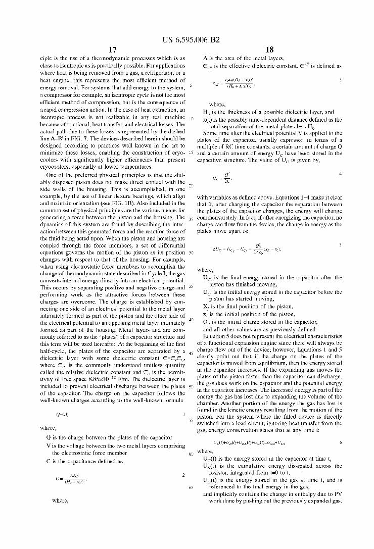
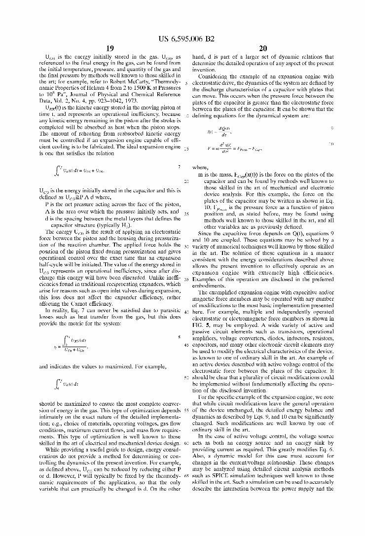
ciple is the use of a thermodynamic processes which is as close to isentropic as is practically possible. For applications where heat is being removed from a gas, a refrigerator, or a heat engine, this represents the most efficient method of energy removal. For systems that add energy to the system, a compressor for example, an isentropic cycle is not the most efficient method of compression, but is the consequence of a rapid compression action. In the case of heat extraction, an H, is the thickness of a possible dielectric layer, and isentropic process is not .(t) is the possibly time-dependent distance defined as the because of frictional, heat transfer, and electrical losses. The actual Path due to these losses is represented by the dashed Some time after the electrical potential V is applied to the line A-B’ in FIG. 7. The devices described herein should be plates of the capacitor, usually expressed in terms of a designed according to Practices well known in the art to multiple of RC time constants, a certain amount of charge Q minimize these losses, enabling the construction of cryo- 15 and a certain amount of energy U, have been stored in the coolers with significantly higher efficiencies than present capacitive structure. The value of U, is given by, cryocoolers, especially at lower temperatures.
One of the preferred physical principles is that the slid-
side walls of the housing. This is accomplished, in one example, by the use of linear flexure bearings, which align with variables as defined above. Equations 1 4 make it clear
common set of physical principles are the various means for the plates of the capacitor changes, the energy will change generating a force between the piston and the housing. The 2s commensurately. In fact, if after energizing the capacitor, no dynamics of this system are found by describing the inter- charge can flow from the device, the change in energy as the action between this generated force and the reaction force of plates move apart is: the fluid being acted upon. When the piston and housing are
A is the area of the metal layers, Eef is the effective dielectric constant. Eef is defined as
G-EO(HO + x(r)) 3 (Ho + w(0) ’ &ef =
where,
in any machine 10
total separation of the metal plates less H,.
Q2 4 uc = -
2C’ ably disposed piston does not make direct contact with the 20
and maintain orientation (see FIG. 1B). Also included in the that if, after charging the capacitor the separation between
coupled through the force members, a set of differential Qi 5 AUc = Uc - Uc = -(xf -x,), equations governs the motion of the piston as its position 30 f ’ 2Aso
changes with respect to that of the housing. For example, when using electrostatic force members to accomplish the change of thermodynamic state described in Cycle I, the gas
U,!,is the final energy stored in the capacitor after the converts internal energy directly into an electrical potential. This occurs by separating positive and negative charge and 3s performing work as the attractive forces between these uc, is the energy stored in the capacitor before the
charges are overcome. The charge is established by con- necting one side of an electrical potential to the metal layer xf i’ the intimately formed as part of the piston and the other side of x~ is the the electrical potential to an opposing metal layer intimately 40 QO is the initial charge stored in the capacitor, formed as part of the housing. Metal layers and are com- and all other values are as previously defined. monly referred to as the ‘‘plates” of a capacitor stmcture and Equation 5 does not represent the electrical characteristics this term will be used hereafter. At the beginning of the first of a functional expansion engine since there Will always be half-cycle, the plates of the capacitor are separated by a 4s charge flow out of the device; however, Equations 1 and 5 dielectric layer with some dielectric constant E=€,€,, clearly Point out that if the charge on the Plates of the where E,, is the common~y understood unitless quantity capacitor is moved from equilibrium, then the energy stored
tivity of free space 8,85x10⁻¹~ F,m, The dielectric layer is plates of the piston faster than the capacitor can discharge, the gas does work on the capacitor and the potential energy included to prevent electrical discharge between the plates so . in the capacitor increases. The increased energy is part of the of the capacitor. The charge on the capacitor follows the energy the gas has lost due to expanding the volume of the chamber. Another portion of the energy the gas has lost is well-known charges according to the well-known formula
found in the kinetic energy resulting from the motion of the piston. For the system where the filled device is directly
ss switched into a load circuit, ignoring heat transfer from the gas, energy conservation states that at any time t:
where,
piston has finished moving,
piston has started moving, position Of the piston, Position Of the Piston,
called the relative dielectric constant and E, is the permit- in the capacitor increases. If the expanding gas the
Q=CK
where,
Q is the charge between the plates of the capacitor V i s the voltage between the two metal layers comprising
C is the capacitance defined as
UC@)+ U&)+ UK&+ U&= UGO+ Uco 6
the electrostatic force member 6o where, U,(t) is the energy stored in the capacitor at time t, U,(t) is the cumulative energy dissipated across the
resistor, integrated from t=O to t, U,(t) is the energy stored in the gas at time t, and is
referenced to the final energy in the gas, and implicitly contains the change in enthalpy due to PV
work done by pushing out the previously expanded gas.
2 AGff (Ho + X(0) ’
C = ~
65
where,
US 6,595,006 B2 19 20
U,, is the energy initially stored in the gas. U,,, as hand, d is part of a larger set of dynamic relations that referenced to the final energy in the gas, can be found from determine the detailed operation of any aspect of the present the initial temperature, pressure, and quantity of the gas and invention. the final pressure by methods well known to those skilled in Considering the example of an expansion engine with the art; for example, refer to Robert McCartY, ‘‘ThermOdY- s electrostatic drive, the dynamics of the system are defined by namic Properties of Helium 4 from 2 to 1500 K at Pressures the discharge characteristics of a capacitor with plates that to 10’ Pa”, Journal of Physical and Chemical Reference can move. This occurs when the pressure force between the Data, Vol. 2, No. 4, pp. 923-1042, 1973. plates of the capacitor is greater than the electrostatic force
stored in the moving Piston at between the plates of the capacitor. It can be shown that the time t, and represents an operational inefficiency, because defining equations for the dynamical system are: any kinetic energy remaining in the piston after the stroke is
is the kinetic
completed will be absorbed as heat when the piston stops. The amount of reheating from reabsorbed kinetic energy dr ’
dQ(0 i(t) = ~
d2X(t) 10
9
must be controlled if an expansion engine capable of effi- cient cooling is to be fabricated. The ideal expansion engine 15 is one that satisfies the relation
F = m ~ = FpreSs - FcaP1 d t2
f uR(r)dr = uco + uco. 7 where, m is the mass, F,,(x(t)) is the force on the plates of the
capacitor and can be found by methods well known to 20 those skilled in the art of mechanical and electronic U,, is the energy initially stored in the capacitor and this is device analysis. For this example, the force on the defined as U,,2P A d where, plates of the capacitor may be written as shown in Eq. P is the net pressure acting across the face of the piston, 10, Fp,, is the pressure force as a function of piston
A is the area over which the pressure initially acts, and position and, as stated before, may be found using d is the spacing between the metal layers that defines the methods well known to those skilled in the art, and all
other variables are as previously defined. The energy uco is the result of applying an electrostatic Since the capacitive force depends on Q(t), equations 9
force between the piston and the housing during pressuriza- and 10 are coupled, These equations may be solved by a tion of the reaction chamber. The applied force holds the 30 variety of numerical techniques well known by those skilled position of the piston fixed during pressurization and gives in the art, The solution of these equations in a manner operational control over the exact time that an expansion consistent with the energy considerations described above half-cycle will be initiated. The value of the energy stored in allows the present invention to effectively operate as an U,, represents an operational inefficiency, since after dis- expansion engine with extremely high charge this energy will have been discarded. Unlike 35 Examples of this operation are disclosed in the preferred ciencies found in traditional reciprocating expanders, which embodiments, arise for reasons such as open inlet valves during expansion, The exemplified expansion engine with capacitive and/or this loss does not affect the expander efficiency, rather magnetic force members may be operated with any number affecting the Carnot efficiency. of modifications to the most basic implementation presented
In reality, Eq. 7 can never be satisfied due to Parasitic 40 here. For example, multiple and independently operated losses electrostatic or electromagnetic force members as shown in provide the metric for the system: FIG. 5, may be employed. A wide variety of active and
passive circuit elements such as transistors, operational amplifiers, voltage converters, diodes, inductors, resistors,
45 capacitors, and many other electronic circuit elements may be used to modify the electrical characteristics of the device, as known to one of ordinary skill in the art. An example of an active device described with active voltage control of the electrostatic force between the plates of the capacitor. It
SO should be clear that a plurality of circuit modifications could be implemented without fundamentally affecting the opera- tion of the disclosed invention.
For the specific example of the expansion engine, we note should be maximized to ensure the most complete conver- that while circuit modifications leave the general operation sion of energy in the gas. This type of optimization depends 55 of the device unchanged, the detailed energy balance and intimately on the exact nature of the detailed implementa- dynamics as described by Eqs. 9, and 10 can be significantly tion; e.g., choice of materials, operating voltages, gas flow changed. Such modifications are well known by one of conditions, maximum current flows, and mass flow require- ordinary skill in the art. ments. This type of optimization is well known to those In the case of active voltage control, the voltage source skilled in the art of electrical and mechanical device design. 60 acts as both an energy source and an energy sink by
While providing a useful guide to design, energy consid- providing current as required. This greatly modifies Eq. 6. erations do not provide a method for determining or con- Also, a dynamic model for this case must account for trolling the dynamics of the present invention. For example, changes in the current/voltage relationship. These changes as defined above, U,, can be reduced by reducing either P may be analyzed using detailed circuit analysis methods or d. However, P will typically be fixed by the thermody- 65 such as SPICE simulation techniques well known to those namic requirements of the application, so that the only skilled in the art. Such a simulation can be used to accurately variable that can practically be changed is d. On the other describe the interaction between the power supply and the
25
capacitor structure (typically H,).
as heat transfer from the gas, but this does
c u R ( r ) d r
uco + UCO ’ 7 =
and indicates the values to maximized. For example,
f u R ( r ) d r
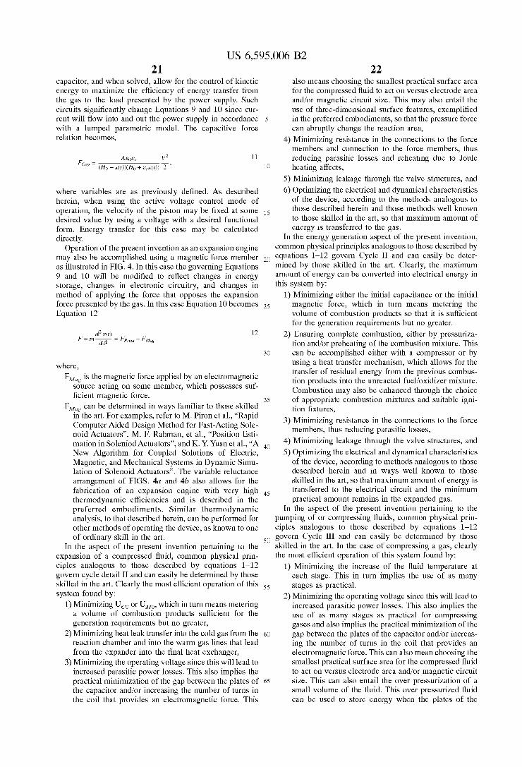
US 6,595,006 B2 21 22
capacitor, and when solved, allow for the control of kinetic energy to maximize the efficiency of energy transfer from the gas to the load presented by the power supply. Such circuits significantly change Equations 9 and 10 since cur- rent will flow into and out the power supply in accordance s with a lumped parametric model. The capacitive force relation becomes,
also means choosing the smallest practical surface area for the compressed fluid to act on versus electrode area and/or magnetic circuit size. This may also entail the use of three-dimensional surface features, exemplified in the preferred embodiments, so that the pressure force can abruptly change the reaction area,
4) Minimizing resistance in the connections to the force members and connection to the force members, thus
11 reducing parasitic losses and reheating due to ‘Joule 10 heating affects,
5) Minimizing leakage through the valve structures, and where variables are as previous~y defined, described 6) Optimizing the electrical and dynamical characteristics herein, when using the active voltage control mode of of the device, according to the methods analogous to operation, the velocity of the piston may be fixed at some 1~ those described herein and those methods well known desired value by using a voltage with a desired functional to those skilled in the art, so that maximum amount of form. Energy transfer for this case may be calculated energy is transferred to the gas. directly. In the energy generation aspect of the present invention,
Operation of the present invention as an expansion engine COmmOn Physical Principles analogous to those described by may also be accomplished using a magnetic force member 2o equations 1-12 govern Cycle 11 and can easily be deter- as illustrated in FIG. 4. In this case the governing Equations mined by those skilled in the art. Clearly, the maximum 9 and 10 will be modified to reflect changes in energy amount of energy can be converted into electrical energy in storage, changes in electronic circuitry, and changes in this system by: method of applying the force that opposes the expansion 1) Minimizing either the initial capacitance or the initial force presented by the gas. In this case Equation 10 becomes 2s magnetic force, which in turn means metering the Equation 12 volume of combustion products so that it is sufficient
for the generation requirements but no greater. 2) Ensuring complete combustion, either by pressuriza-
tion and/or preheating of the combustion mixture. This can be accomulished either with a comuressor or bv
12
30
where, FMag is the magnetic force applied by an electromagnetic
source acting on some member, which possesses suf- ficient magnetic force.
FMag can be determined in ways familiar to those skilled in the art. For examples, refer to M. Piron et al., “Rapid Computer Aided Design Method for Fast-Acting Sole- noid Actuators”, M. F. Rahman, et al., “Position Esti- mation in Soleniod Actuators”, and K. Y. Yuan et al., “A 4o New Algorithm for Coupled Solutions of Electric,
3s
using a heat transfer mechanism, which allows for the transfer of residual energy from the previous combus- tion products into the unreacted fuelioxidizer mixture. Combustion may also be enhanced through the choice of appropriate combustion mixtures and suitable igni- tion fixtures,
3) Minimizing resistance in the connections to the force members, thus reducing parasitic losses,
4) Minimizing leakage through the valve structures, and 5) Optimizing the electrical and dynamical characteristics
of the device, according to methods analogous to those described herein and in ways well known to those skilled in the art, so that maximum amount of energy is transferred to the electrical circuit and the minimum practical amount remains in the expanded gas.
In the aspect of the present invention pertaining to the
- Magnetic, and Mechanical Systems in Dynamic Simu- lation of Solenoid Actuators”. The variable reluctance arrangement of FIGS. 4a and 4b also allows for the fabrication of an expansion engine with very high 4s thermodynamic efficiencies and is described in the preferred embodiments. Similar thermodynamic analysis, to that described herein, can be performed for other methods of operating the device, as known to one of ordinary skill in the art.
In the aspect of the present invention pertaining to the expansion of a compressed fluid, common physical prin- ciples analogous to those described by equations 1-12 govern cycle detail I1 and can easily be determined by those skilled in the art. Clearly the most efficient operation of this ss system found by:
1) Minimizing U,, or U,,, which in turn means metering a volume of combustion products sufficient for the generation requirements but no greater,
2) Minimizing heat leak transfer into the cold gas from the 60 reaction chamber and into the warm gas lines that lead from the expander into the final heat exchanger,
3) Minimizing the operating voltage since this will lead to increased parasitic power losses. This also implies the practical minimization of the gap between the plates of 65 the capacitor and/or increasing the number of turns in the coil that provides an electromagnetic force. This
pumping of or compressing fluids, common physical prin- ciples analogous to those described by equations 1-12
so govern Cycle I11 and can easily be determined by those skilled in the art. In the case of compressing a gas, clearly the most efficient operation of this system found by:
1) Minimizing the increase of the fluid temperature at each stage. This in turn implies the use of as many stages as practical.
2) Minimizing the operating voltage since this will lead to increased parasitic power losses. This also implies the use of as many stages as practical for compressing gases and also implies the practical minimization of the gap between the plates of the capacitor and/or increas- ing the number of turns in the coil that provides an electromagnetic force. This can also mean choosing the smallest practical surface area for the compressed fluid to act on versus electrode area and/or magnetic circuit size. This can also entail the over pressurization of a small volume of the fluid. This over pressurized fluid can be used to store energy when the plates of the
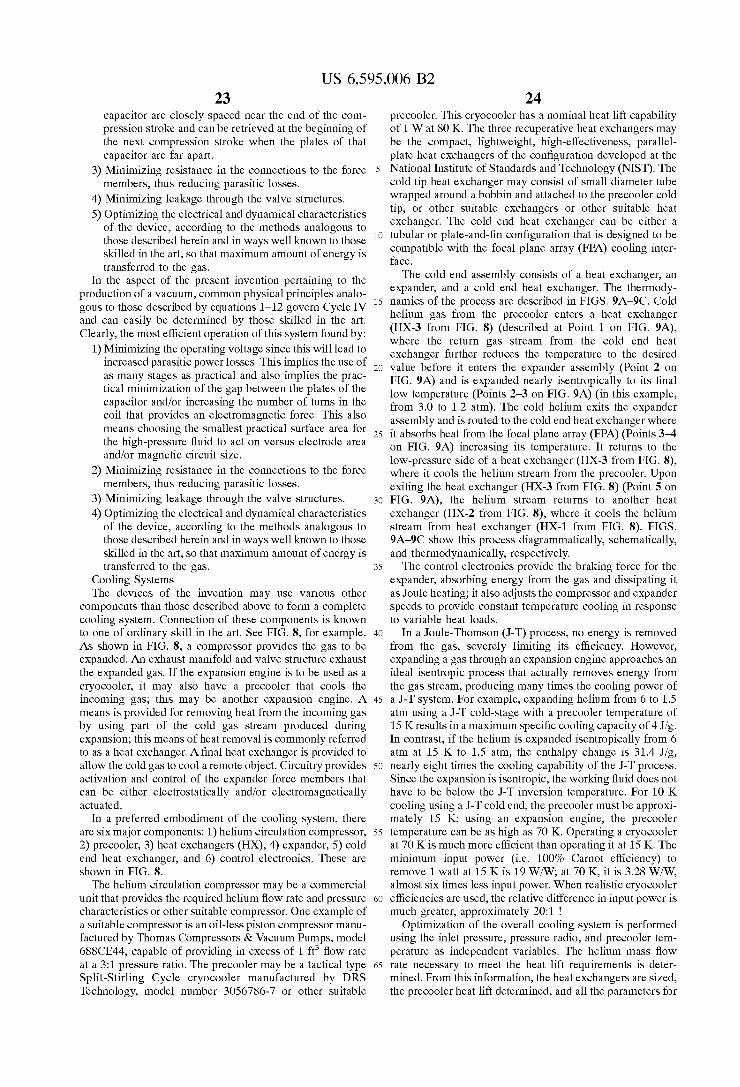
US 6,595,006 B2 23
capacitor are closely spaced near the end of the com- pression stroke and can be retrieved at the beginning of the next compression stroke when the plates of that capacitor are far apart.
3) Minimizing resistance in the connections to the force members, thus reducing parasitic losses.
4) Minimizing leakage through the valve structures. 5) Optimizing the electrical and dynamical characteristics
of the device, according to the methods analogous to those described herein and in ways well known to those skilled in the art, so that maximum amount of energy is transferred to the gas.
In the aspect of the present invention pertaining to the production of a vacuum, common physical principles analo- gous to those described by equations 1-12 govern Cycle IV and can easily be determined by those skilled in the art. Clearly, the most efficient operation of this system found by:
1) Minimizing the operating voltage since this will lead to increased parasitic power losses. This implies the use of as many stages as practical and also implies the prac- tical minimization of the gap between the plates of the capacitor and/or increasing the number of turns in the coil that provides an electromagnetic force. This also means choosing the smallest practical surface area for the high-pressure fluid to act on versus electrode area and/or magnetic circuit size.
2) Minimizing resistance in the connections to the force members, thus reducing parasitic losses.
3) Minimizing leakage through the valve structures. 4) Optimizing the electrical and dynamical characteristics
of the device, according to the methods analogous to those described herein and in ways well known to those skilled in the art, so that maximum amount of energy is transferred to the gas.
Cooling Systems The devices of the invention may use various other
components than those described above to form a complete cooling system. Connection of these components is known to one of ordinary skill in the art. See FIG. 8, for example. As shown in FIG. 8, a compressor provides the gas to be expanded. An exhaust manifold and valve structure exhaust the expanded gas. If the expansion engine is to be used as a cryocooler, it may also have a precooler that cools the incoming gas; this may be another expansion engine. A means is provided for removing heat from the incoming gas by using part of the cold gas stream produced during expansion; this means of heat removal is commonly referred to as a heat exchanger. A final heat exchanger is provided to allow the cold gas to cool a remote object. Circuitry provides activation and control of the expander force members that can be either electrostatically and/or electromagnetically actuated.
In a preferred embodiment of the cooling system, there are six major components: 1) helium circulation compressor, 2) precooler, 3) heat exchangers (HX), 4) expander, 5) cold end heat exchanger, and 6) control electronics. These are shown in FIG. 8.
The helium circulation compressor may be a commercial unit that provides the required helium flow rate and pressure characteristics or other suitable compressor. One example of a suitable compressor is an oil-less piston compressor manu- factured by Thomas Compressors & Vacuum Pumps, model 688CE44, capable of providing in excess of 1 ft3 flow rate at a 3: l pressure ratio. The precooler may be a tactical type Split-Stirling Cycle cryocooler manufactured by DRS Technology, model number 3056786-7 or other suitable
S
10
1s
20
2s
30
3s
40
4s
so
5s
60
65
24 precooler. This cryocooler has a nominal heat lift capability of 1 W at 80 K. The three recuperative heat exchangers may be the compact, lightweight, high-effectiveness, parallel- plate heat exchangers of the configuration developed at the National Institute of Standards and Technology (NIST). The cold tip heat exchanger may consist of small diameter tube wrapped around a bobbin and attached to the precooler cold tip, or other suitable exchangers or other suitable heat exchanger. The cold end heat exchanger can be either a tubular or plate-and-fin configuration that is designed to be compatible with the focal plane array (FPA) cooling inter- face.
The cold end assembly consists of a heat exchanger, an expander, and a cold end heat exchanger. The thermody- namics of the process are described in FIGS. 9A-9C. Cold helium gas from the precooler enters a heat exchanger (HX-3 from FIG. 8) (described at Point 1 on FIG. 9A), where the return gas stream from the cold end heat exchanger further reduces the temperature to the desired value before it enters the expander assembly (Point 2 on FIG. 9A) and is expanded nearly isentropically to its final low temperature (Points 2-3 on FIG. 9A) (in this example, from 3.0 to 1.2 atm). The cold helium exits the expander assembly and is routed to the cold end heat exchanger where it absorbs heat from the focal plane array (FPA) (Points 3 4 on FIG. 9A) increasing its temperature. It returns to the low-pressure side of a heat exchanger (HX-3 from FIG. S), where it cools the helium stream from the precooler. Upon exiting the heat exchanger (HX-3 from FIG. 8) (Point 5 on FIG. 9A), the helium stream returns to another heat exchanger (HX-2 from FIG. S), where it cools the helium stream from heat exchanger (HX-1 from FIG. 8). FIGS. 9A-9C show this process diagrammatically, schematically, and thermodynamically, respectively.
The control electronics provide the braking force for the expander, absorbing energy from the gas and dissipating it as Joule heating; it also adjusts the compressor and expander speeds to provide constant temperature cooling in response to variable heat loads.
In a Joule-Thomson (J-T) process, no energy is removed from the gas, severely limiting its efficiency. However, expanding a gas through an expansion engine approaches an ideal isentropic process that actually removes energy from the gas stream, producing many times the cooling power of a J-T system. For example, expanding helium from 6 to 1.5 atm using a J-T cold-stage with a precooler temperature of 15 K results in a maximum specific cooling capacity of 4 Jig. In contrast, if the helium is expanded isentropically from 6 atm at 15 K to 1.5 atm, the enthalpy change is 31.4 Jig, nearly eight times the cooling capability of the J-T process. Since the expansion is isentropic, the working fluid does not have to be below the J-T inversion temperature. For 10 K cooling using a J-T cold end, the precooler must be approxi- mately 15 K, using an expansion engine, the precooler temperature can be as high as 70 K. Operating a cryocooler at 70 K is much more efficient than operating it at 15 K. The minimum input power (i.e. 100% Carnot efficiency) to remove 1 watt at 15 K is 19 W/W; at 70 K, it is 3.28 W/W, almost six times less input power. When realistic cryocooler efficiencies are used, the relative difference in input power is much greater, approximately 20:l !
Optimization of the overall cooling system is performed using the inlet pressure, pressure radio, and precooler tem- perature as independent variables. The helium mass flow rate necessary to meet the heat lift requirements is deter- mined. From this information, the heat exchangers are sized, the precooler heat lift determined, and all the parameters for
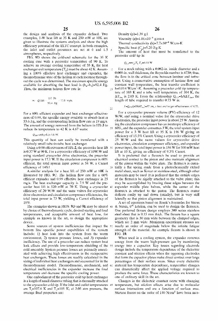
US 6,595,006 B2 25
the design and analysis of the expander defined. Two examples, 1-W heat lift at 35 K and 250 mW at 10K are given to illustrate the systems analysis and show the high efficiency potential of the ELTC concept. In both examples, the inlet and outlet pressures are set at 6 and 1.5 atmospheres, respectively.
FIG. 9D shows the cold-end schematic for the 35 K cooling case with a precooler temperature of 90 K. To achieve an average cooling temperature of 35 K, the heat exchanger exit temperature (T2) must be about 42 K. Assum- ing a 100% effective heat exchanger and expander, the thermodynamic state of the helium at each location through- out the cycle was determined. The maximum specific energy available for absorbing the heat load is (h,-h,)=92.4 Jig. Thus, the minimum helium flow rate is:
1.0 Jls m=Q/Ah=- = 10.8 mgk.
92.4 Jlg
For a 60% efficient expander and heat exchanger effective- ness of 0.99, the specific energy available to absorb heat is 53.6 Jig, and the corresponding helium flow rate is 19 mgis. The amount of energy removed from the helium in HX-3 to reduce its temperature to 42 K is 4.67 watts:
QH~m(h1-hz)=4.67W
This quantity of heat can easily be transferred with a relatively small tube-in-tube heat exchanger.
Using a 0.98 effectiveness of HX-2, the precooler heat lift is 0.37 W at 90 K. For a cryocooler efficiency of 10WW and using standard cryocooler drive electronics, the precooler input power is 17.1 W. If the circulation compressor is 60% efficient, the total system input power is 54 W, a Carnot efficiency of 14%!
A similar analysis for a heat lift of 250 mW at 10K is illustrated by FIG. 9C. The helium flow rate for a 60% efficient expander and 0.99 effective heat exchanger is 25 mgis. The heat exchanger capacity is 7.9 W and the pre- cooler heat lift is 520 mW at 70 K. Using a cryocooler efficiency of 20 W/W and the same values for cryocooler drive electronics and circulation compressor efficiencies, the total input power is 73 W, yielding a Carnot efficiency of 10%.
The examples shown in FIGS. 9D and 9E may be altered by choice of thermodynamic cycle, desired starting and final temperatures, and acceptable amount of heat loss, for example as known in the art, to design the appropriate device.
Some sources of system inefficiencies that impact the bottom line specific power capabilities of the system include: 1) heat leak into the system from the warm environment, 2) system pressure losses, and 3) expander inefficiency. The use of a precooler can reduce system heat leak effects and provide low-temperature shielding of the cold assembly. System pressure losses are primarily associ- ated with achieving high effectiveness in the recuperative heat exchangers. These losses are readily calculated in the sizing of individual heat exchangers and accounted for in the thermodynamic model. Thermodynamic, mechanical, and electrical inefficiencies in the expander increase the final temperature and decrease the specific cooling power.
One embodiment of the precooler cold tip heat exchanger is a length of small diameter tubing that is thermally attached to the cryocooler cold tip. If the inlet and outlet temperatures are Ti=107.6 K and T,=105 K, at 3.05 atm pressure, the average fluid properties are:
S
10
1s
20
2 s
30
3s
40
4s
so
5s
60
65
26 Density (p)=1.39 g/l Viscosity @)=1.01~10-~ gicm-s Thermal conductivity (k)=7.7~10-, Wicm-K Specific heat (Cp)=5.20 Jig-K The amount of heat that must be transferred to the
precooler cold tip is:
Qc~mc,,(T1-To)=1.06 W
For a stock tubing with a 0.082-in. inside diameter and a 0,009-in. wall thickness, the Reynolds number is 4730; thus, the flow is in the critical zone between laminar and turbu- lent. Using a conservative assumption of laminar flow and constant wall temperature, the heat transfer coefficient is h=0.014 W/cm2-K. Assuming a precooler cold tip tempera- ture of 103 K and a tube wall temperature of 104 K, the ATlm is 2.03 K. From the relationship QcFhAATlm, the length of tube required to transfer 0.73 W is:
L=Qc,/(nOhATl,)=S7 cm, a heat exchanger effectiveness of 0.72.
For a cryocooler pressure volume (PV) efficiency of 12 W/W, and using a nominal value for the cryocooler drive electronics, the precooler input power is about 25 W. Assum- ing the circulation compressor has an isentropic efficiency of 60%, and the expander consumes 3 W, the total system input power for a 3 W heat lift at 35 K is 146 W giving an efficiency of 15.5% Carnot. Using a cryocooler efficiency of 25 W/W and the same values for cryocooler drive electronics, circulation compressor efficiency, and expander power input, the total input power is 156 W for 500 mW heat lift at 10 K, giving an efficiency of 9.3% Carnot.
It is preferred that a flexureis be used to provide an electrical contact to the piston and also maintain alignment of the piston within the valve plate. The flexureis is essen- tially a flat spring made from a photochemically etched metal sheet, such as Kovar or stainless steel, although other materials may be used. It is preferred that the outside edges of the flexureis be rigidly attached to the valve plate; this may be accomplished by brazing these edges between the expander middle plate halves, while the center of the flexureis is attached to the piston. The flexureis center deflects easily up and down (axially), but is very stiff laterally so that piston alignment is maintained.
A set of equations based on Roark’s Formulas for Stress & Strain, 6th Edition, can be used to design the flexureis. One preferred flexure design employs 300 series stainless steel sheet that is 0.15 mm thick. The flexure has a square geometry that is 30 mm wide between the clamped edges, which are 2 mm wide. Maximum operational stresses are nearly an order of magnitude below the infinite fatigue strength of the material. An example flexure is shown in FIG. 10.
When used in a cooling system, the expander removes energy from the warm high-pressure gas by transferring energy into a capacitor. Key issues regarding electrode design include the temperature dependence of the dielectric constant and stiction effects when the opposing electrodes that form the capacitor plates make direct contact over large percentages of their surface areas. Since every dielectric material has temperature dependence, temperature changes can dramatically affect the applied voltage required to produce the same force. These characteristics are known to one of ordinary skill in the art.
Changes in the dielectric constant occur with changing temperature, but stiction effects arise due to molecular surface interactions and are a function of surface area. Stiction forces on the order of 140 N/cm2 have been mea-
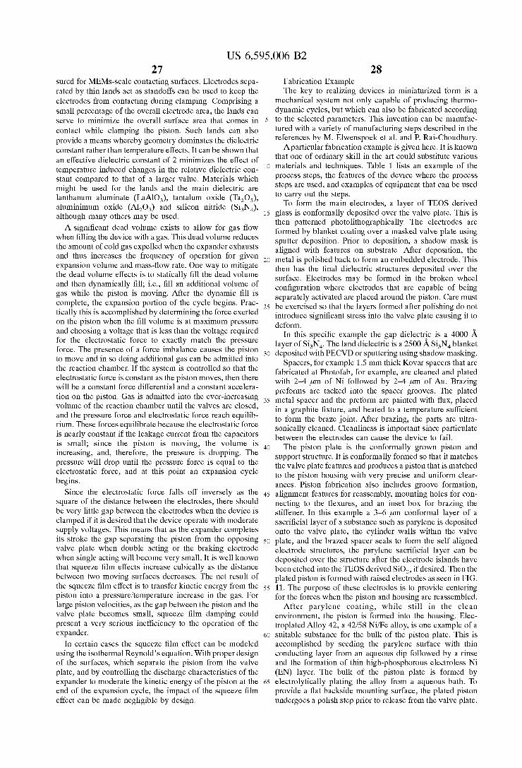
US 6,595,006 B2 27
sured for MEMs-scale contacting surfaces. Electrodes sepa- rated by thin lands act as standoffs can be used to keep the electrodes from contacting during clamping. Comprising a small percentage of the overall electrode area, the lands can serve to minimize the overall surface area that comes in contact while clamping the piston. Such lands can also provide a means whereby geometry dominates the dielectric constant rather than temperature effects. It can be shown that an effective dielectric constant of 2 minimizes the effect of temperature induced changes in the relative dielectric con- stant compared to that of a larger value. Materials which might be used for the lands and the main dielectric are lanthanum aluminate (LaAlO,), tantalum oxide (Ta,O,), aluminimum oxide (A1203) and silicon nitride (Si3N4), although many others may be used.
A significant dead volume exists to allow for gas flow when filling the device with a gas. This dead volume reduces the amount of cold gas expelled when the expander exhausts and thus increases the frequency of operation for given expansion volume and mass-flow rate. One way to mitigate the dead volume effects is to statically fill the dead volume and then dynamically fill; i.e., fill an additional volume of gas while the piston is moving. After the dynamic fill is complete, the expansion portion of the cycle begins. Prac- tically this is accomplished by determining the force exerted on the piston when the fill volume is at maximum pressure and choosing a voltage that is less than the voltage required for the electrostatic force to exactly match the pressure force. The presence of a force imbalance causes the piston to move and in so doing additional gas can be admitted into the reaction chamber. If the system is controlled so that the electrostatic force is constant as the piston moves, then there will be a constant force differential and a constant accelera- tion on the piston. Gas is admitted into the ever-increasing volume of the reaction chamber until the valves are closed, and the pressure force and electrostatic force reach equilib- rium. These forces equilibrate because the electrostatic force is nearly constant if the leakage current from the capacitors is small; since the piston is moving, the volume is increasing, and, therefore, the pressure is dropping. The pressure will drop until the pressure force is equal to the electrostatic force, and at this point an expansion cycle begins.
Since the electrostatic force falls off inversely as the square of the distance between the electrodes, there should be very little gap between the electrodes when the device is clamped if it is desired that the device operate with moderate supply voltages. This means that as the expander completes its stroke the gap separating the piston from the opposing valve plate when double acting or the braking electrode when single acting will become very small. It is well known that squeeze film effects increase cubically as the distance between two moving surfaces decreases. The net result of the squeeze film effect is to transfer kinetic energy from the piston into a pressureitemperature increase in the gas. For large piston velocities, as the gap between the piston and the valve plate becomes small, squeeze film damping could present a very serious inefficiency to the operation of the expander.
In certain cases the squeeze film effect can be modeled using the isothermal Reynold’s equation. With proper design of the surfaces, which separate the piston from the valve plate, and by controlling the discharge characteristics of the expander to moderate the kinetic energy of the piston at the end of the expansion cycle, the impact of the squeeze film effect can be made negligible by design.
28 Fabrication Example The key to realizing devices in miniaturized form is a
mechanical system not only capable of producing thermo- dynamic cycles, but which can also be fabricated according
s to the selected parameters. This invention can be manufac- tured with a variety of manufacturing steps described in the references by M. Elwenspoek et al. and P. Rai-Choudhury.
Aparticular fabrication example is given here. It is known that one of ordinary skill in the art could substitute various
i o materials and techniques. Table 1 lists an example of the process steps, the features of the device where the process steps are used, and examples of equipment that can be used to carry out the steps.
To form the main electrodes, a layer of TEOS derived is glass is conformally deposited over the valve plate. This is
then patterned photolithographically. The electrodes are formed by blanket coating over a masked valve plate using sputter deposition. Prior to deposition, a shadow mask is aligned with features on substrate. After deposition, the
20 metal is polished back to form an embedded electrode. This then has the final dielectric structures deposited over the surface. Electrodes may be formed in the broken wheel configuration where electrodes that are capable of being separately activated are placed around the piston. Care must
zs be exercised so that the layers formed after polishing do not introduce significant stress into the valve plate causing it to deform.
In this specific example the gap dielectrg is a 4000 layer of Si,N,. The land dielectric is a 2500 A Si,N, blanket
30 deposited with PECVD or sputtering using shadow masking. Spacers, for example 1.5 mm thick Kovar spacers that are
fabricated at Photofab, for example, are cleaned and plated with 2 4 pm of Ni followed by 2-4 pm of Au. Brazing preforms are tacked into the spacer grooves. The plated
3s metal spacer and the preform are painted with flux, placed in a graphite fixture, and heated to a temperature sufficient to form the braze joint. After brazing, the parts are ultra- sonically cleaned. Cleanliness is important since particulate between the electrodes can cause the device to fail.
The piston plate is the conformally grown piston and support structure. It is conformally formed so that it matches the valve plate features and produces a piston that is matched to the piston housing with very precise and uniform clear- ances. Piston fabrication also includes groove formation,
4s alignment features for reassembly, mounting holes for con- necting to the flexures, and an inset box for brazing the stiffener. In this example a 3-6 pm conformal layer of a sacrificial layer of a substance such as parylene is deposited onto the valve plate, the cylinder walls within the valve
SO plate, and the brazed spacer seals to form the self aligned electrode structures, the parylene sacrificial layer can be deposited over the structure after the electrode islands have been etched into the TEOS derived SO,, if desired. Then the plated piston is formed with raised electrodes as seen in FIG.
ss 11. The purpose of these electrodes is to provide centering for the forces when the piston and housing are reassembled.
After parylene coating, while still in the clean environment, the piston is formed into the housing. Elec- troplated Alloy 42, a 42/58 Ni/Fe alloy, is one example of a
60 suitable substance for the bulk of the piston plate. This is accomplished by seeding the parylene surface with thin conducting layer from an aqueous dip followed by a rinse and the formation of thin high-phosphorous electroless Ni (EN) layer. The bulk of the piston plate is formed by
65 electrolytically plating the alloy from a aqueous bath. To provide a flat backside mounting surface, the plated piston undergoes a polish step prior to release from the valve plate.
40
US 6,5! 29
The piston and housing are separated thermally. This is accomplished by heating the low temperature co-fired ceramic (LTCC) substrate and cooling the piston sufficiently to separate the plated metal from the parylene surface.
Next, the parylene sacrificial layer is removed from the valve plate via ashing, at 350” C. or less in an 0, ambient. After the bulk sacrificial layer has been removed, the valve plate is cleaned using an 0, plasma. After thorough oxidation, the valve plate is cleaned to remove particulate.
After separation, the piston is machined, either conven- tionally or using microfabrication techniques to trim back the edges and to form through holes for the mitigation of squeeze film effects. Indexing is from the piston edge and center. To form the fill volume, the piston head is polished down to the specified gap distance.
The piston is attached to the mounting pins in the flexure by soldering the pins into the mounting holes on the back of the piston. After cleaning the mounted piston flexure assembly, solder preforms are tacked into place on the valve plates. The piston and valve plate are then aligned and joined.
The alignment process is accomplished using high preci- sion positioners with differential capacitance feed-back which minimizes capacitance differences between the split electrodes and the piston. The difference signal between the capacitors is minimized by x and y translation of the precision x, y, z stage. After minimizing the difference between each capacitor, the z positioner brings the valve plate closer to the piston. Since the electrodes on the valve plate have been patterned photolithographically, the area of each electrode segment is nearly identical and as the piston moves closer; the differential capacitance values should remain nearly constant. If not, the piston and housing are not level. In this case, the leveling of the stage is used to minimize differential capacitance values. After leveling, the z travel is backed off, and x, y differential capacitance minimization repeated. Finally, the piston is moved com- pletely into contact with the valve plate. End of travel is determined when there is no change in the capacitance of the alignment features for increasing drive current to the posi- tioner. At this point, the alignment circuit is disconnected, and the piston and housing are electrostatically clamped. After alignment of the piston and electrostatically clamping to the electrodes on the midplate and the entire assembly is heated to form the sealing joints.
The valves for the assembly are then attached. Valves such as those disclosed in U.S. Pat. No. 5,380,396 may be used in this device and they may be fabricated with methods consistent with that teaching. The valves are vacuum brazed onto the valve plate providing hermetic mechanically sound seals, which also form one part of the electrical contact to the valve. After mounting, the remaining two electrical contacts to the valves are made using wire bonding. Finally mani- folds are mounted in such a way as to form seals around the valves, this can be done using brazing or epoxy bonds. FIG. 12 shows valve manifolds and attachments to a valve plate. FIG. 13 shows the overall expander assembly.
REFERENCES 5,457,956 October 1995 Bowman et al.; 5,941,079
August 1999 Bowman et al; 5,932,940 August 1999 Epstein et al.; 6,109,889 August 2000 Zengerle et al.; 6,106,245
S
10
1s
20
2s
30
3s
40
4s
so
5s
60
65
,006 B2 30
August 2000 Cabuz et al.; 6,109,222 August 2000 Glezer et al.; 5,336,062 August 1994 Richter et al.; 6,019,882 Febru- ary 2000 Paul et al.; 5,788,468 August 1998 Dewa et al.; 5,871,336 April 1999 Young; 6,157,029 December 2000 Chutjian et a1.;5,763,998 June 1998 Colombo et al.; M. Elwenspoek et al., “Silicon Micromachining,” Cambridge University Press, 1998; P. Rai-Choudhury (Editor), “Hand- book of Microli thography, Micromachining, and Microfabrication,” SPIE Press, 1997; K. S. Breuer et al., “Challenges for High-speed Lubrication in MEMS,” book chapter in NanoTribology, Ed. S. Hsu, Kluwer Press (to appear 2000); R. Remsburg, “Advanced Thermal Design of Electronic Equipment,” Chapman Hall, 1997. E. Simoen, et. a1 “The Cryogenic Operation of partially Depleted Silicon- on-Insulator Inverters”, IEEE Transactions on Electron Devices, Vol. 42, No. 6, pp. 1100-1105, 1995; P. Ghazavi, et. a1 “A Numerical Model for MOSFET’s from Liquid- Nitrogen Temperature to Room Temperature”, IEEE Trans- actions on Electron Devices, Vol. 42, No. 1, pp. 123-134, 1995; Robert McCarty, “Thermodynamic Properties of Helium 4 from 2 to 1500 K at Pressures to 10’ Pa,” Journal of Physical and Chemical Reference Data, Vol. 2, No. 4, pp. 923-1042, 1973; M. Piron et al., “Rapid Computer Aided Design Method for Fast-Acting Solenoid Actuators,” IEEE Transactions on Industry Applications, Vol. 35, No. 5, pp. 991-999, 1999. M. F. Raman et al., “Position Estimation in Solenoid Actuators,” IEEE Transactions on Industry Applications, Vol. 32, No. 3, pp. 552-558, 1996; K. Y. Yuan et al., “A New Algorithm for Coupled Solutions of Electric, Magnetic, and Mechanical Systems in Dynamic Simulation of Solenoid Actuators,” IEEE Transactions on Magnetics,
All references cited herein are hereby incorporated by reference to the extent not inconsistent with the disclosure herewith. Although the description herein contains much specificity, this should not be construed as limiting the scope of the invention, but as merely providing illustrations of some of the presently preferred embodiments of the inven- tion. For example, in addition to the piston shapes described herein, pistons of other geometrical shape can be used in this invention without changing the operation of the disclosed invention; e.g., cylindrical pistons. In these cases, the hous- ing will conform to the new piston shape. Other designs for valves may be used without fundamentally affecting the operation of the disclosed invention. Other designs for manifolds may be used without fundamentally affecting the operation of the disclosed invention. Other designs for the capacitor structure may be used without fundamentally affecting the operation of the disclosed invention. Other designs for magnetic structures may be used without fun- damentally affecting the operation of the disclosed inven- tion. Other designs for an ignition system may be used without fundamentally affecting the operation of the dis- closed invention. Other circuit elements can be used in this invention without changing the operation of the disclosed invention. For example, elements may be added such as passive elements such as inductors, transformers, and capacitors arranged into other Thevenin equivalent networks, active devices such as transistors, operational amplifiers etc. We do not wish to be bound by the theory presented herein.
Vol. 26, NO. 3, pp. 1189-1197, 1990.
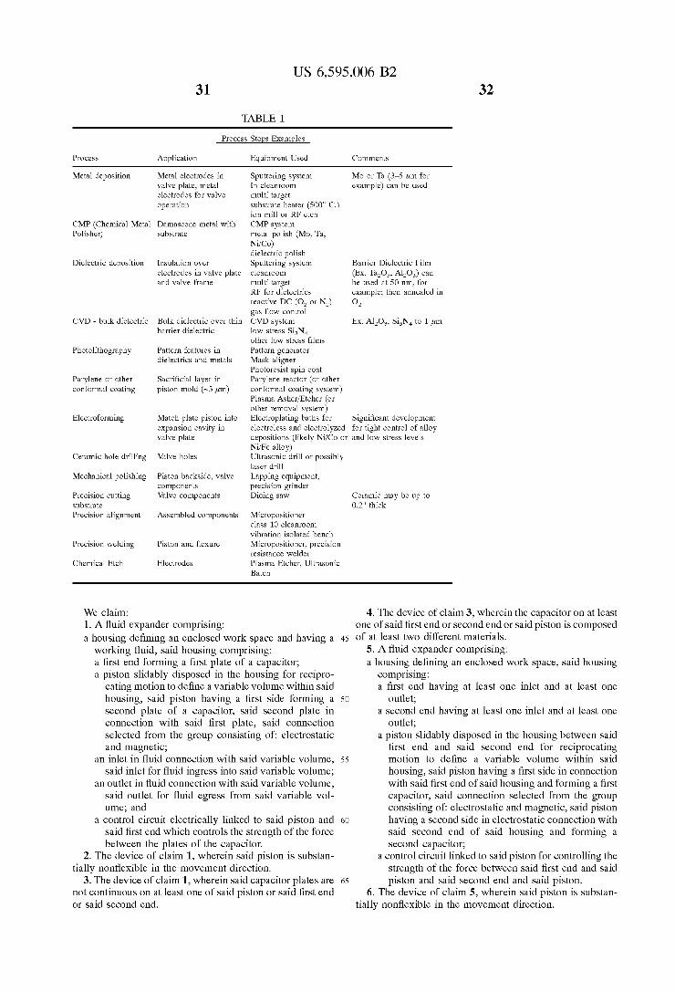
31
TABLE 1
US 6,595,006 B2 32
Process Steps Examples
Process Application Equipment Used Comments
Metal deposition
CMP (Chemical Metal Polisher)
Dielectric deposition
CVD - bulk dielectric
Photolithography
Parylene or other conformal coating
Electroforming
Ceramic hole drilling
Mechanical polishing
Precision cutting substrate Precision alignment
Precision welding
Chemical Etch
Metal electrodes in valve plate, metal electrodes for valve operation
Damascene metal with substrate
Insulation over electrodes in valve plate and valve frame
Bulk dielectric over thin barrier dielectric
Pattern features in dielectrics and metals
Sacrificial layer in piston mold (-3 ,urn)
Match plate piston into expansion cavity in valve plate
Valve holes
Piston backside, valve components Valve components
Assembled components
Piston and flexure
Electrodes
Sputtering system In cleanroom multi target substrate heater (500" C.) ion mill or RF etch CMP system metal polish (Mo, Ta, NiiCo) dielectric polish Sputtering system cleanroom multi-target RF for dielectrics reactive DC (0, or NZ, gas flow control CVD system low-stress Si,N, other low stress films Pattern generator Mask aligner Photoresist spin coat Parylene reactor (or other conformal coating system) Plasma AsheriEtcher (or other removal system) Electroplating baths for electroless and electrolyzed
Mo or Ta (3-5 ,um for example) can be used
Barrier Dielectric Film (Ex. Ta,O,, A1,0,) can be used at SO nm, for example; then annealed in 0,
Ex. A1,0,, Si,N, to 1 ,um
Significant development for tight control of alloy
depositions (likely NiiCo or and low stress levels NiiFe alloy) Ultrasonic drill or possibly laser drill Lapping equipment, precision grinder Dicing saw
Micropositioner class 10 cleanroom vibration isolated bench Micropositioner, precision resistance welder Plasma Etcher, Ultrasonic Batch
Ceramic may be up to 0.2" thick
We claim: 1. A fluid expander comprising: a housing defining an enclosed work space and having a
working fluid, said housing comprising: a first end forming a first plate of a capacitor; a piston slidably disposed in the housing for recipro-
cating motion to define a variable volume within said housing, said piston having a first side forming a second plate of a capacitor, said second plate in connection with said first plate, said connection selected from the group consisting of electrostatic and magnetic;
an inlet in fluid connection with said variable volume, said inlet for fluid ingress into said variable volume;
an outlet in fluid connection with said variable volume, said outlet for fluid egress from said variable vol- ume; and
a control circuit electrically linked to said piston and said first end which controls the strength of the force between the plates of the capacitor.
2. The device of claim 1, wherein said piston is substan- tially nonflexible in the movement direction.
3. The device of claim 1, wherein said capacitor plates are not continuous on at least one of said piston or said first end or said second end.
4. The device of claim 3, wherein the capacitor on at least one of said first end or second end or said piston is composed
45 of at least two different materials. 5 . A fluid expander comprising: a housing defining an enclosed work space, said housing
comprising: a first end having at least one inlet and at least one
so outlet; a second end having at least one inlet and at least one
outlet; a piston slidably disposed in the housing between said
first end and said second end for reciprocating 55 motion to define a variable volume within said
housing, said piston having a first side in connection with said first end of said housing and forming a first capacitor, said connection selected from the group consisting of electrostatic and magnetic, said piston having a second side in electrostatic connection with said second end of said housing and forming a second capacitor;
a control circuit linked to said piston for controlling the strength of the force between said first end and said piston and said second end and said piston.
6. The device of claim 5, wherein said piston is substan-
60
65
tially nonflexible in the movement direction.
US 6,595,006 B2 33
7. The device of claim 5, wherein said capacitor plates are not continuous on at least one of said piston or said first end or said second end.
8. The device of claim 7, wherein the capacitor on at least one of said first end or second end or said piston is composed of at least two different materials.
9. Amethod of expanding a gas, said method comprising: applying a clamping force between a piston slidably
disposed in a housing and a first end of said housing, wherein said piston moves toward said first end but does not contact said first end;
allowing a working fluid to enter the space between said first end of said housing and said piston;
releasing the clamping force between said piston and said first end, whereby said piston moves away from said first end and said working fluid is isentropically expanded.
10. A method of expanding a gas, said method compris-
applying a clamping force between a piston slidably disposed in a housing and a first end of said housing, said housing defining an enclosed work space and said housing comprising a first end having at least one inlet and at least one outlet and a second end having at least one inlet and at least one outlet, wherein said piston moves toward said first end but does not contact said first end;
allowing a working fluid to enter the space between said first end of said housing and said piston;
reducing the clamping force between said piston and said first end, wherein said working fluid is isentropically expanded and said piston moves away from said first end and toward said second end;
applying a clamping force between said piston and said second end of said housing, wherein said piston moves toward said second end but does not contact said second end;
allowing a working fluid to enter the space between said second end of said housing and said piston;
reducing the clamping force between said piston and said second end, wherein said working fluid is isentropically expanded and said piston moves away from said second end and toward said first end.
ing:
11. A method of generating power comprising: placing a combustible substance in the first end of a
housing having a first end and a second end and a piston slidably disposed in said housing for reciprocating motion to define a variable volume within said housing, said piston having a first side in connection with said first end of said housing and forming a first capacitor and a second side in connection with said second end of said housing and forming a second capacitor, said connection selected from the group consisting o f elec- trostatic and magnetic; energizing said piston by apply- ing a force to said piston so that said piston is moved toward said first end;
igniting said combustible substance, thereby increasing the temperature and pressure in said first end;
reducing the force on said piston; allowing said combustible substance to expand against
12. The method of claim 11, further comprising transfer-
13. The method of claim 11, further comprising: placing a combustible substance in the second end of said
said piston, thereby generating power.
ring said power through a circuit.
housing;
34 energizing said piston by applying a force to said piston
so that said piston moves toward said second end; igniting said combustible substance, thereby increasing
the temperature and pressure in said second end; reducing the force on said piston; allowing said combustible substance to expand against
14. The method of claim 11, further comprising: transferring said power from said housing through a
15. A method of generating power comprising: applying a clamping voltage between the first end of a
housing and a piston slidably disposed in said housing and in electrical or magnetic connection with first end of said housing;
admitting heated gas or fluid into the first end of a housing;
reducing the clamping force on said piston; allowing said piston to expand away from said first end,
16. The method of claim 15, further comprising: transferring said power from said housing through a
17. A method of pumping a substance comprising: placing a compressible substance in the first end of a
housing having a first end having at least one inlet and at least one outlet, a second end having at least one inlet and at least one outlet, a piston slidably disposed in the housing between said first end and said second end for reciprocating motion to define a variable volume within said housing, said piston having a first side in electro- static or magnetic connection with said first end of said housing and forming a first capacitor, said piston hav- ing a second side in electrostatic connection with said second end of said housing and forming a second capacitor;
energizing said piston by applying a force to said piston so that the piston moves toward said first end, whereby the temperature and pressure of the compressible sub- stance are increased;
removing said compressible substance from the first end of said housing.
18. The method of claim 17, further comprising placing a compressible substance in the second end of said housing, energizing said piston by applying a force to said piston so that the piston moves toward said second end, whereby the temperature and pressure of the compressible substance are
so increased; removing said compressible substance from the second end of said housing.
said piston, thereby generating power.
circuit.
1s
20
thereby generating power.
circuit. 2s
30
3s
4o
4s
19. A cooling system comprising: a cooler in thermal connection with an object to be cooled; a compressor comprising a housing having a first end
having at least one inlet and at least one outlet, a second end having at least one inlet and at least one outlet,
a piston slidably disposed in the housing between said first end and said second end for reciprocating motion to define a variable volume within said housing, said piston having a first side in connection with said first end of said housing and forming a first capacitor, said connection selected from the group consisting o f elec- trostatic and magnetic, said piston having a second side in electrostatic connection with said second end of said housing and forming a second capacitor; and means for providing control to said device, said compressor in fluid or gas connection with said cooler;
5s
60
65
US 6,595,006 B2 35
a heat exchanger in fluid or gas connection with said compressor and said cooler.
20. A cooling system comprising: a precooler; a compressor in fluid connection with said precooler; a first heat exchanger in fluid connection with said com-
pressor; an expander in fluid or gas connection with said first heat
exchanger, said expander comprising a first end having at least one inlet and at least one outlet,
a second end having at least one inlet and at least one outlet,
a piston slidably disposed in the housing between said first end and said second end for reciprocating motion to define a variable volume within said housing, said piston having a first side in connection with said first end of said housing and forming a first capacitor, said connection selected from the group consisting o f elec- trostatic and magnetic, said piston having a second side in electrostatic connection with said second end of said housing and forming a second capacitor;
a second heat exchanger in fluid or gas connection with said expander;
control electronics which are in electrical connection with said expander and said compressor.
21. The cooling system of claim 20, which provides
22. The cooling system of claim 20, which provides
23. The cooling system of claim 20, which provides
24. The cooling system of claim 20, which provides
25. The cooling system of claim 20, which provides
26. A cooling system comprising: a precooler; a compressor in fluid connection with said precooler; a first heat exchanger in fluid connection with said com-
pressor; an expander in fluid connection with said first heat
exchanger, said expander comprising: a first end having at least one inlet and at least one
outlet; a second end having at least one inlet and at least one
outlet; a piston slidably disposed in the housing between said
first end and said second end for reciprocating motion to define a variable volume within said housing, said piston having a first side in connection with said first end of said housing and forming a first capacitor, said connection selected from the group consisting of electrostatic and magnetic, said piston having a second side in electrostatic connection with said second end of said housing and forming a second capacitor, said expander in fluid connection with said cooler;
a second heat exchanger in fluid connection with said expander;
control electronics in electrical connection with said expander and said compressor.
27. A method for mechanical voltageienergy conversion
applying a force between a first end of a housing and a piston in a housing having a first end having at least one
cooling at 150K or below.
cooling at 70K or below.
cooling at 45K or below.
cooling at 35K or below.
cooling at 10K or below.
comprising:
36 inlet and at least one outlet, a second end having at least one inlet and at least one outlet, and a piston slidably disposed in the housing between said first end and said second end for reciprocating motion to define a variable volume within said housing, said piston having a first side in connection with said first end of said housing and forming a first capacitor, said connection selected from the group consisting of electrostatic and magnetic, said piston having a second
side in electrostatic connection with said second end of said housing and forming a second capacitor;
5
10
opening said inlet to said first end; inserting gas into said first end through said inlet; reducing the force between said first end and said
piston so that said piston is able to move; closing the inlet valve to said first end, whereby the gas
in said first end expands, increasing the electrical potential between the first end and the piston.
28. A device containing a dielectric structure, which minimizes temperature effects in the dielectric, said device comprising:
1s
20
a first end having one dielectric constant; a piston slidably disposed in the device for reciprocating
motion to define a variable volume within said device, said piston having a first side having a different dielec- tric constant than said first end, said piston in connec- tion with said first end of said device and forming a first capacitor, said connection selected from the group consisting of electrostatic and magnetic.
29. A method for operating an electrostatic piston in a device comprising a housing having a first end having an inlet and an outlet and a second end having an inlet and an
3s outlet; a piston slidably disposed in the housing between said first end and said second end for reciprocating motion to define a variable volume within said housing, said piston having a first side in connection with said first end of said housing, said connection selected from the group consisting
40 of electrostatic and magnetic, and forming a first capacitor or electromagnetic force member, said piston having a second side in connection with said second end of said housing and forming a second capacitor or electromagnetic force member, said method comprising:
2s
3o
4s opening the inlet to the first end comprising:
placing an compressible substance in a first end; closing the inlet to the first end; compressing said compressible substance by electro-
statically energizing the piston toward the first end with the inlet to the second end open and the outlet to the second end closed;
opening the outlet to the first end until the desired amount of compressible substance is removed, but before all the compressible substance is removed;
closing the outlet to the first end; clamping the piston by applying an appropriate force
and further increasing the pressure of the remaining compressible substance;
60 reducing the force between the piston and the electrostatically/electromagnetically energized member of the first end so that the energy of the compressed substance causes the piston to accelerate toward the second end;
so
5s
65 opening the inlet to the first end.
* * * * *
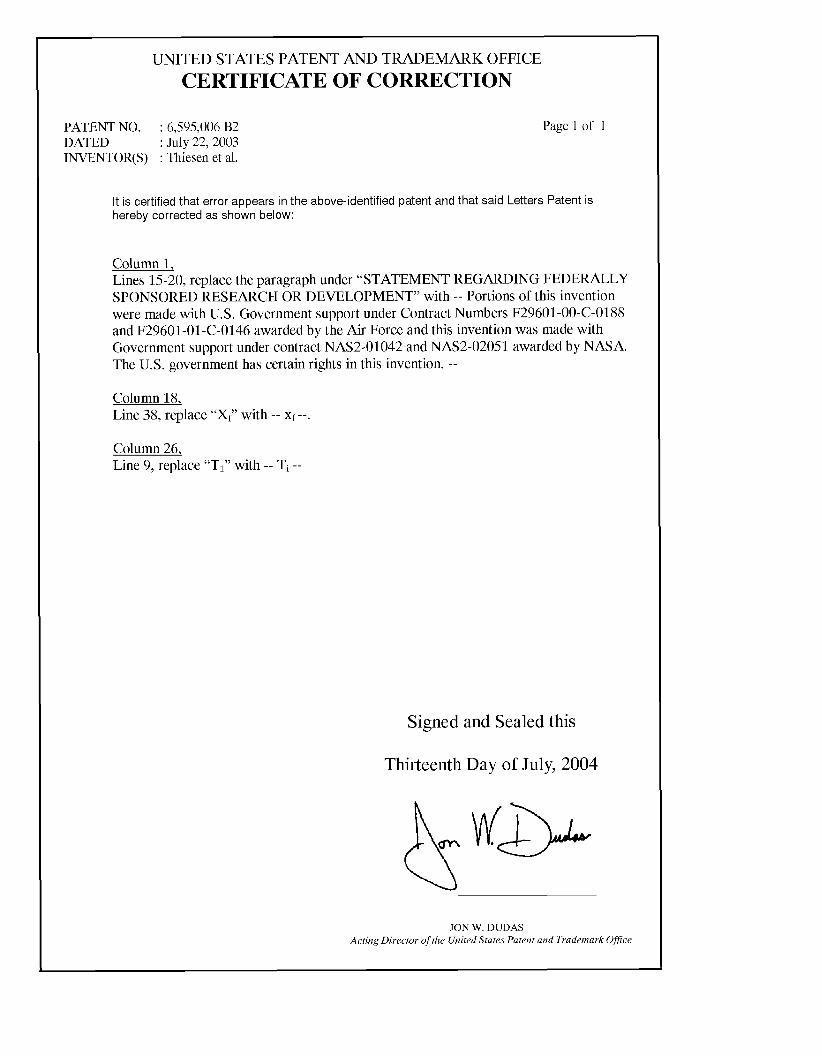
UNITED STATES PATENT AND TRADEMARK OFFICE CERTIFICATE OF CORRECTION
PATENT NO. : 6,595,006 B2 DATED : July 22,2003 INVENTOR(S) : Thiesen et al.
Page 1 of 1
It is certified that error appears in the above-identified patent and that said Letters Patent is hereby corrected as shown below:
Column 1, Lines 15-20, replace the paragraph under “STATEMENT REGARDING FEDERALLY SPONSORED RESEARCH OR DEVELOPMENT” with -- Portions of this invention were made with U.S. Government support under Contract Numbers F29601-00-C-0188 and F29601-01-C-0146 awarded by the Air Force and this invention was made with Government support under contract NAS2-01042 and NAS2-02051 awarded by NASA. The U.S. government has certain rights in this invention. --
Column 18, Line 38, replace ‘‘Xf)’ with -- xf --.
Column 26, Line 9, replace “TI” with -- Ti --
Signed and Sealed this
Thirteenth Day of July, 2004
JON W. DUDAS Acting Director of the United States Patent and Trademark Ofice


![I11111 111111ll111 Ill11 Ill11 IIIII Ill11 Ill11 IIIII ...I11111 111111ll111 Ill11 Ill11 IIIII Ill11 Ill11 IIIII 11111 IIIII 11ll11111111111111 US006001426A United States Patent [19]](https://static.fdocuments.net/doc/165x107/5f08cf707e708231d423d4c6/i11111-111111ll111-ill11-ill11-iiiii-ill11-ill11-iiiii-i11111-111111ll111-ill11.jpg)
