i gnal n rat rs - QSL.net · i gnal n rat rs 2 and 2 1 (80 kHz -- 520MHz) Code NOe 52018-910P and...
56
Operating Manual H 52 8-910P Vole 1 i gnal n rat rs 2 and 2 1 (80 kHz -- 520 MHz) Code NOe 52018-910P and combination versions in 2018-400 series from 52018-401R to 52018-413N (80 kHz -- 1040 MHz) Code NOe 52019-910E and combination versions in 2019-400 series from 52019-401L to 52019-413P Feb.85 (Am.2) Instruments Ltd. 1984 Printed in the UK Part No. 46881-511A Print code: F-10/86, MI 6.0c Page i
Transcript of i gnal n rat rs - QSL.net · i gnal n rat rs 2 and 2 1 (80 kHz -- 520MHz) Code NOe 52018-910P and...

Operating Manual
H 52 8-910P
Vole 1
i gnal n rat rs
2 and 2 1
(80 kHz -- 520 MHz)Code NOe 52018-910P
and combination versionsin 2018-400 series
from 52018-401Rto 52018-413N
(80 kHz -- 1040 MHz)Code NOe 52019-910E
and combination versionsin 2019-400 series
from 52019-401Lto 52019-413P
Feb.85 (Am.2)
~Marconi Instruments Ltd. 1984Printed in the UK
Part No. 46881-511APrint code: F-10/86, MI 6.0c
Page i

H 52018-910PVol. 1
CONTENTS
PRELIMINARIES
Title pageContentsNotes and cautions
CHAPTERS
12345678
General informationInstallationOperationTechnical descriptionMaintenanceReplaceable partsServicing diagramsModifications andsuppLemen t s
These chapters are contained in aseparate volume available as anop t Lona.L extra.
HAZARD WARNING SYMBOLS
The following symbols appear on the equipment.
Symbol Type of hazard Reference in manual
&. Static sensitive device Page (iv)
M Component containin.g beryllia Page (iv)B9IYLUA
No t e
Each page bears the date of the original issue or the code number anddate of t h e latest amendme n t (Am. 1, AM. 2 e t c , ) , New or amendedmaterial of technical importance intrvduced by the latest amendment isindicated by triangles positioned t hus ~ ••••• <lilt to show the extent of thechange. ~fuen a chapter is reissued t he triangles do not appear ..
Any changes subsequent to the latest amendment state of the manual areincluded on inserted sheets coded Cl, C2 etc.
Page ii Jun. 84

H 52018-910PVol. 1
NOTES AND CAUTIONS
ELECTRICAL SAFETY PRECAUTIO~S
This equipment is protected' in accordance with lEe Safety Class 1. Ithas been designed and tested according to lEe Publication 348, 'SafetyRequirements for Electronic Measuring Apparatus', and has been supplied in asafe condition. The following precautions must be observed by the user toensure safe operation and to retain the equipment in a safe condition.
Whenever it is likely that protection has been impaired, for exalnple as aresult of damage caused by severe conditions of transport or storage, theequipment shall be made inoperative and be secured against any unintendedoperation.
Removal of covers
Removal of the covers is likely to expose live parts although reasonableprecautions have been taken in the design of the equipment to shield suchparts. The equipment shall be disconnected from the supply before carryingout any ad jus tnen t , repLacemerit or maintenance and repair during which theequLpmen t 8118,.11 be opened. If any adjustment, maintenance or repair undervoltage is inevitable it shall only be carried out by a skilled person who isaware of the hazard involved.
Note t ha t capaci tors inside the equipment may still be charged when theequipment has been disconnected from the supply. Before carrying out anywork inside the equipment, capacitors connected to high voltage points shouldbe discharged; to discharge mains filter capacitors, if fitted, shorttogether the L (live) and N (neutral) pins of the mains plug.
The mains plug shall only be inserted in a socket outlet provided with aprotective earth contact. The protective action shall not be negated by theuse of an extension lead wi t hout; protective conductor. Any interruption ofthe protective conductor inside or outside the equipment is likely to make theequipment dangerous.
Fuses
Note that there is a supply fuse in both the live and neutral wires ofthe supply lead. If only one of these fuses $hould rupture, certain parts ofthe equipment could remain at supply potential.
To provide protection a g a inst b r e a k d own of the supply lead, itsconnectors, and filter where fitted, an external supply fuse (e.g. fitted tothe connecting, plug) shouLd be used in the live lead. The fuse should have acontinuous rating not exceeding 6 A.
Make sure that only fuses with the required rated current and of thespecified type are used for replacement. The use of mended fuses and theshort-circuiting of fuse holders shall be avoided.
Jun. 84 Page iii

H 52018-910PVol. 1
_RADIO ~REQUENCY INTERF~~NCE
This equipment conforms with the requirements of lEe Directive 76/889 asto limits of r.f. interference.
CAUTION: STATIC .SENSITIVE COMPONENTS
Componen t s identified wi.t h the symbol ~ on the circuit d.i ag r ams and/orparts lists are static sensitive devices. The presence of such devicesis also indicated in the equipment by orange discs, flags or labelsbearing the same sy~bol. Certain handling precautions must be observedto prevent these components being permanently damaged by static chargesor fast surgese
(1) If a printed board containing static sensitive components (asindicated by a warning disc or flag) is removed, it must be temporarilystored in a conductive plastic bag.
(2) If a static sensitive component is to be removed or replaced thef o Ll.owf.ng anti-static equipment must be used.
A work bench with an earthed conductive surface.
Metallic tools earthed either permanently or by repeated discharges.
A low-voltage earthed' soldering iron.
An earthed wrist strap and a conductive earthed seat cover for theoperator, whose outer. clothing must not be of man.....made fibre.
(3) As a general precaution, avoid touching the leads of a staticsensitive component. When handling a new one, leave it in itsconducting mount until it is required for use.
(4) If using a freezer aerosol in fault findings take care not to sprayp r ogr ammab Le IGs as this may affect their contents.
CAUTION: LCD HANDLIN·G·
When operating or servicing this equ1pment take care not to depress thefront or rear faces of the display module as this may damage the liquidcrystal display elements.
WARNING HANDLING HAZARDS
This equipment Ls formed from metal pressings and although everyendeavour has been made to remove sharp points and edges care should betaken, particularly when servicing the equipment, to avoid minor cuts.
WARNING: TOXIC HAZARD
Many of the electronic components used in ~his equipment employ resins.an d other chemicals which give off toxic fumes on Ln c Lne r a t Lo n ,Appropriate precautions should therefore be taken in ·the disposal ofthese Lt ems It
Page iv Jun. 84

H 52018-910PVol. 1
&. Beryllia (beryllium oxide) is used in the construction of the followingcomponents in this equipment
Unit AC4 : Transistor TRIO...............................................................This material, when in the form of fine dust or vapour and inhaled intothe lungs, can cause a respiratory disease. In its solid form, as usedhere, it can be handled quite safely although it is prudent to avoidhandling conditions which promote dust formation by surface abrasion.
Because of this hazard you are advised to be very careful in removing anddisposing of these components. Do not put them in the generalindustrial or domestic waste or despatch them by post. They must. beseparately and securely packed and clearly identified to show the natureof the hazard and then disposed of in a safe manner by an authorizedtoxic waste contractor.
Jun. 84 Page v


H 52018--910PVol. 1
Chapter 1
GENERAL INFORMATION
CONTENTS
Para.1 Features3 Output4 }'lodulation5 Front panel7 Variants 2018A/2019A8 Performance data9 Carrier frequency 2018A/2019A
10 RF output 2018A/2019A11 Spurious signals 2018A/2019A12 Frequency modulation 2018A/2019A14 Carrier frequency15 RF output16 Spurious signals17 Frequency modulation18 Phase modulation19 Amplitude modulation20 Pulse modulation21 AF oscillator22 Frequency standard23 Auxiliary inputs and outputs24 Keyboard and displays25 GPIB interface26 Environmental27 Safety28 Radio frequency interference29 Power requirements30 Weight and dimensions31 Accessories31 Supplied accessories32 Optional accessories
Fig. Page1 80 kHz to 1040 }ffiz Mtl/FM Syn t hes Laed Signal Generator 2019A ••• 2
FEATURES
1. 2018A and 2019A are stable, a.m./f.m. synthesized signal generators.2018A covers the frequency range 80 kHz to 520 MHz. 2019A includes afrequency doubler which increases the frequency range to 1040 ~lliz. Both arephase locked to a frequency standard and can be set to a resolution of 10 Hzat frequencies up to 520 MHz, and in the case of 2019A resolution of 20 Hz forfrequencies above 520 }ffiz.
Jun. 84Chap. 1
Page 1

H 52018-910PVol. 1
Fig. 1 80 kHz to 1040 MHz AM/FM Synthesized Signal Generator 2019A
2. Front panel operation is carried out by direct entry of required settingsvia the ·keyboard. Microproce~sor control ensures maximum flexibility andallows programming by the General Purpose Interface Bus (GPIB).* Thisfacility is offered as an optional accessory enabling the instrument to beused both as a manually operated bench mounted instrument or as part of afully automated test system. Provision is also made for the use of either111Hz or 10 MHz ex t e rnaL standard frequency reference when this is preferred.
3 Calibrated output levels from -127 dBm to +13 clBm (OG2 ~V to 2 V e.m.f.)in the c.w., f sm , and cp.m. modes and up to +7 d Bm (1 V e s ms f , ) in the a s m,mode are provided. A choice of nine output level calibration units can beobtained on the front panel. The raf. output level can be set to ar e s o Lu t Lon of 0.1 dB or better over the' entire output voltage 'range andfeatures a total cumulative accuracy of ±l dB up to 520 MHz (±2 dB, 520 MHz 1040 MHz)@ Protection against the accidental application of up to 50 W ofreverse power is provided by a fast responding reed relay.
4 Ampli tude and frequency modulat ion can be carried out from ei t he r,
external or internal modulati.on s ou r c e s , The internal modulation sourceprovides six fixed modulation frequencies suitable for most normalapplications.
*GPIB ...... Marconi Lus t r ument s General Purpose Interface Bus in accordance withIEEE Standard 488 ...... 1978 and lEe Publication 625-1 and BS 6146 Pt. 1.

H 52018-910PVol. 1
Front panel
5. The instrument settings are displayed by three liquid crystal displaysthat include annunciators to show the units of the displayed data. All datais entered on a keyboard chat; has been designed to be simple and logical touse. Non-volatile store and recall facilities are also provided by using anelectrically alterable read only memory store that does not require a batteryback-up system. Carrier frequency, f s m, , <p.m., avm , , r.f., and a s f , levelfunctions may be incremented or decremented using the up/down keys.
6. Second function mode of operation. This includes the means of settingthe GPIB address, selection of alternative r s f , level calibration um t s ,access to various calibration routines, instrument running hours and an identity string that displays instrument type, software issue and serial number.Up to 32 ASCII characters may also be stored in non-volatile memory by theuser via the GPIB bus. Modulation input level status information is al~o
available via the GPIB bus if required.
Variants
7. Four individual variants are available in both 2018A and 2019A. As Lug Le option or a combination Lnvo LvLng up to three of the four options maybe fitted to the instrument, these are as follows:-
(1) (Extended f.m.) bandwidth, stereo and digital signalling capability.
( 2) (Avionics) providing the capability for testi-ng VOR & 118.
( 4) (10 kHz Carrier) frequency extended range.
(8) (Pulse Mod)ulation.
Single s CombLnat Lon options
52018- or 52019- (1) (2) (4) (8)
401R 401L Extended f.m.402B 402J Avionics403K 403F Extended f 18m. Avionics404A 404G 10 kHz Carrier4052 405V Extended f .m. IG kHz Carrier408U 408D Pulse Mod409Y 409T Extended f .m. Pul.3e Mod410E 410W Avionics Pulse Mod411U 411D Extended f 8m. Avionics Pulse Modt+12Y 412T 10 k-Hz Carrier Pulse t10d413N 413P Extended f.m. 10 kHz Carrier Pulse Mod
Confirmation of the variant(s) fitted can be obtained by comparing the numberon the identification plate affixed to t h e rear of the instrument and theabove list.
Jun. 84Chap. 1
Page 3

H 520.18.....910PVol = 1
PERFORMANCE DATA
8. The performance specifications for2018A and 2019A are in most respectsidentical, therefore t he following data applies to both instruments exceptwhere otherwise stated. Other variants having different parameters ares p e cLf Le d o n Lywhe r e a more limiting parameter applies. Where a combinationof options causes a parameter to be specified more than once then the morelimiting parameter will apply. Alternative parameter information that isspecific. to a variant is shown in bold type.
Characteristic Performance
2018A version 2019A version
9. Range: 80 kHz to 520 MHz (usabledown to 30 kHz) ..
80 kHz to 1040 ill1z (usabledown to 30 kHz) It
AVIONICS VARIANTS
Range: 1.5 MHz to 520 MHz 1.5 MHz to 1040 MHz
10 kHz CARRIER VARIANTS
Range:
Resolution:
10 kHz to 520 MHz
10 Hz up to 520 MHz
10 kHz to 1040 MHz
10 Hz up to 520 MHz20 Hz f rom 520 MHz
to 1040 MHz
10. Level accuracy: ±1 dB ±l dB from 80 kHz to 520 MHz±2 dB f r om 520 MHz to 1040 r-1Hz
AVIONIC VARIANTS
Level accuracy: ±2 dB from 1.5 MHz ±2 dB from 1.5 MHz to 5 MHzto 5 MHz
±1 dB from 5 MHz ±1 dB from .5 MHz to 520· MHzto 520 MHz ±2 dB from 520 MHz to 1040 MHz
10 kHz CARRIER VARIANTS
Level accuracy: ±1 dB from 10 kHzto 520 MHz
Chap. 1Page 4
±l dB from 10 kHz to 520 MHz±2 dB from 520 .MHz to l040MHz
Jun. 84

Characteristic
H 52018.....910PVol. 1
Performance
2018A version 2019A version
PULSE MOD VARIANTS
Level accuracy:(With pulse mod
not selected)
Level accuracy(With pulse modselected and +5Vapplied to input,i.e. Carrier on)
±l dB from 80 kHzto 520 MHz
±1.5 dB from 10 MHzto 520 MHz
Note
±l dB from 80 kHz to 520 MHz±3 dB from 520 MHz to 1040 MHz
±1.5 dB from 10 MHz to 520 MHz±4.5 dB from 520 MHz to l040MHz
With pulse mod selected the maximum outputlevel is reduced to +3 dBm.
VSWR:(for output levels
below 300 mVe.m.f.)
Spurioup signals
11. Harmonicallyrelated signals:for output levels<1 V e.m.f.)
Sub.....harmonics
Frequency modulation
<.....30 dBc forcarrier fre~
quencies from80 kHz to 520 MHz
None
<1,. 2 : 1 ) up to 520 l\ffiz,<1.5:1, 520 MHz to 1040 MHz
<.....30 dBc for carrier frequenciesfrom 80 kllz to 520 MHz<-20 dBc for carrier frequenciesfrom 520 MHz to 1040 MHz.
<-20 dBc for carrier frequenciesfrom 520 MHz to 1040 MHz.
12. Resolution
Jun. 84
3 digits or 10 Hz (whichever is the la~ger) upto 520 MHz.
3 digits or 10 Hz (whichever is the larger) up to520 MHz.3 digits or 20 Hz (whichever is the larger) up to1040 MHz.
Chap. 1Page 5

Characteristic Performance
H 52018-910PVol. 1
13. The remaining characteristics are common to both 2018A and 2019A.
Carrier frequency
14. Selection:
Frequency indication:
Accuracy:
RF, output
15. Level:
Selection:
Display~
Resolution:
Output impedance:
Reverse power protection:
Spurious signals
16. Non-harmonically relatedsignals:
Chap. 1Page 6
By keyboard entry.
8 digit l.e.d. ~ for details see underKeyboard and displays.
Equal to the frequency standardaccuracy ~ see under Frequencystandard.
0.2 uV to 2 V e s ms f , (=-127 to +13 d Bm )in c~w. and f~m. modes.0.2 ~V to 1 V eom.f. (~127 to +7 dBm)when a.m. is selected.
By keyboard entry ~ units may be~V, mV, V, e@mof. or p.d. ordB relative to 1 ~V, 1 mV, 1 V,earn.f. or p.d. or dBm.
Conversion between dB and voltage unitsmay be achieved by pressing theappropriate unit key (dB or V, mV, ~V).
4 digit l.c.d. with units annunciators- see under Keyboard and displays.
0.1 dB or better over entire voltagerange.
50 Q, Type N female socket toMIL 39012/3D.
An electronic trip protects thegenerator output against reverse powerof up to 50 W from d.c. to 1 GHz. Thetrip may be reset from the front panelor via the GPIB.
<-70 dBc at offset frequencies greaterthan 3 kHz for carrier frequencies from2.03126 MHz to 1040 MHz.<-60 dBc at offset frequencies greaterthan 3 kHz for carrier frequencies from80 kHz to 2.03125 MHz.
Jun. 84

Characteristic
Residual f .rn , :
Single side band phase noise:
RF leakage:
Frequency modulatiou_
17. Range:
Selection:
Display:
Deviation accuracy:
Frequency response:
Frequency response:
Jun. 84
H 52018....910PVol. 1
Performance
Less than 6 Hz rem.s. in celTT telephonepsophometric band at 520 MHz and improvingby approximately 6 dB/octave with reducingcarrier frequency down to 2.03126 -~lz.
Better than -130 dBc/Hz at 9011Hz and20 kHz offset from carrier.
Less than 005 ~V p.d. generated in a 50 ~
load by a 2 turn 25 rom loop, 25 rom or morefrom the case of the generator with theoutput level set to less than -10 dBm andthe output terminated in a 50 n sealedload.
(i) Peak deviation from 0 Hz to up to 1%of carrier frequency for carrierfrequencies f r om 2.03126 "MHz to 1040 MHz.
(ii) Peak deviation from 0 Hz to 100 kHzfor carrier frequencies up to2.03125 MHz.
Internal modulation oscillator or externalmodulation input may be selected by thefront panel keyboard.
3 digit l.e.d. - see under keyboard anddisplays.
±5% of deviation at 1 kHz modulatingfrequency excluding residual f.m.
±l dB from 50 Hz to 100 kHz relative to1 kHz. Usable down to 10 Hz with reduceddeviation.
EXTENDED FM VARIANTS
±l dB from 50 Hz to 100 kHz relative to1 kHz.Usable down to 1 Hz with reduced deviation.The instrument is suitable for testingreceivers requiring signalling tones witha frequency modula.tion content down to1 Hz.Settling time with FM on is up toapproximately 5 seconds to be within100 Hz of final frequency.
Chap. 1Page 7
Characteristic
Stereo separation:
Distortion:
External modulation:
Phase modulation
18. Range:
Selection:
Display:
Frequency response:
Accuracy:
Chap. 1Page 8
H 52018-910PVol.l
Performance
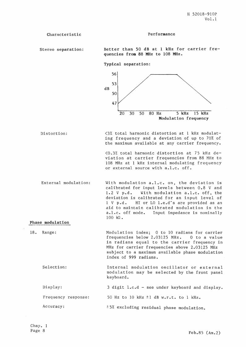
Better than 50 dB at 1 kHz for carrier frequencies from 88 MHz to 108 MHz.
Typical separation:
56
53dB
50
47
20 30 50 80 Hz 5 kHz 15 kHzModulation frequency
<3% total harmonic distortion at 1 kHz modulating frequency and a deviation of up to 70% ofthe maximum available at any carrier frequency.
<0.3% total harmonic distortion at 75 kHz deviation at carrier frequencies from 88 MHz to108 MHz at 1 kHz internal modulating frequencyor external source with a.l.e. off.
With modulation a.l.c. on, the deviation iscalibrated for input levels between 0.8 V and1.2 V p.d. With modulation a.l.c. off, thedeviation is calibrated for an input level of1 V p sd , HI or LO Lve sd .... s are provided as anaid to maintain calibrated modulation in thea.l.c. off mode. Input impedance is nominally100 kn.
Modulation index; 0 to 10 radians for carrierfrequencies below 2.03125 MHz. 0 to a valuein radians equal to the carrier frequency inMHz for carrier frequencies above 2.03125 MHzsubject to a maximum available phase modulationindex of 999 radians.
Internal modulation oscillator or externalmodulation may be selected by the front panelkeyboard.
3 digit l.c.d - see under keyboard and display.
50 Hz to 10 kHz ±1 dB w.r.t. to 1 kHz.
±5% excluding residual phase modulation.
Feb.8S (Am.2)

tCharacteristic
External modulRtion:
Distortion:
Amplitude modulation
19. Range:
SeLec t Lou :
Display:
Accuracy :
Frequency response:
Frequency response:
Envelope distortion:
ILS perfor·mance:
Jun. 84
H 52018-910PVol & 1
Performance
With modulation a.l.e. on, the -deviation iscalibrated for input levels between 0.8 Vand 1.2 V p.d. With modulation a.l.c. off,the deviation is calibrated for an inputlevel of 1 V p.d. HI or LO l.e.d's areprovided as an aid to maintain calibratedmodulation in the a.loc. off mode. Inputimpedance is nominally 100 ~Q.
<3% total narmonic distortion at 1 kHzmodulating frequency and at maximumdeviation (equal to the carrier frequencyin MHz) at,any carrier frequency.
o to 99% in 1% steps.
Internal modulation oscillator or externalmodulation input may be selected.
2 digit l.e.d. - see under keyboard anddisplay.
Better than ± (4% of depth setting +1%) formodulation depths up to 95% and 1 kHzmodulating frequency for carrierfrequencies up to 400 MHz.
±l dB from 20 Hz to 50 kHz relative to1 kHz at 80% depth d.c. coupled.
10 kHz CARRIER VARIANTS
At 10 kHz carrier frequency AM is usablewith up to 1 kHz mod. rate.
Less than 3% total harmonic distor.tion formodulation depths up to 80% at 1 kHzmodulating frequency for carrierfrequencies up to 400 ~ffiz.
Less than 2% total harmonic distortion formodulation depths up to 90% at 1 kHzmodulating frequency for carrierfrequencies up to 32 MHz.
AVIONICS VARIANTS
~O.045% a.m. difference in depth ofmodulation for ILS tones at 90 Hz and150 Hz each at 40% modulation depth.
Chap. 1Page 9

Characteristic
External modulati.on input:
Pulse modulation
20. Carrier pulse response:
Carrier on/off ratio:
Propagation delay pulseinput to carrier pulse:
Input:
Selection and display:
AF oscillator
21. Frequencies:
Display:
Frequency accuracy:
Internal AF OSCoutput:
Chap. 1Page 10
H 52018-910PVol. 1
Performance
With the modulation a.l.c. on, themodulation depth is calibrated for inputlevels between 0.8 V and 1.2 V p.d.With the modulation a.l.c. off, themodulation depth is calibrated for aninput level of 1 V p.d. HI or La l.e.d'sare provided as an aid to maintaincalibrated modulation in the a.l.c. offmode. Input impedance is nominally100 "kS1, d. c. coupled.
PULSE MOD VARIANTS
Rise time (lOa nsFall time <100 ns
>65 dB at 70 MHz carrier frequency,reducing to
>50 dB at 520 MHz carrier frequency andthen to
>35 dB at 800 MHz carrier frequency(usable to 1040
Typically 280 ns
Rear panel BNC connectorInput impedance 50 gNominal signal levels 0 V for carrier off,+5 V for carrier on
Pulse modulation is selected by pressingAM ~M
the two keys [PULSE PULSE] simultaneously,
followed by the MOD ON-OFF key. Themodulation window then displays P and EXT.
300 Hz, 400 Hz, 500 Hz, 1 k.Hz , 3 k-Hz and6 kHz selected sequentially by repetitivepressing of the AF OSC key.
Six l.e.d's indicate selected frequency.
±5 %
A front panel BNC socket provides anoutput for the AF signal.
Jun. 84

Characteristic
Output level selection:
Output level accuracy:
Maxilnum au t pu t :
Distortion
Source impedance
Frequency standard
22ft
Frequency standard Input/Output:
Internal standard:
Temperature stability:
War'm-up time:
Jun. 84
H 52018-910PVol. 1
Performance
0.1 mV to 5 V r.m.s., selected by keyboardentry. Output may be entered in mV, V oras dBm into 600 Q. Conversion between dBand voltage units may be achieved bypressing the appropriate key (dB,mV,V).The output frequency is always that of theAF OSC and is short circuit proof. Atswitch-on the AF level is set to 1 v.
±5% above SO mV r.m.s.±10% from 0.5 mV to 50 mV r.m.s.
Capable of driving a 2 kQ load for outputlevels up to 5 V r.m.s.Capable of driving a 600 n load for outputlevels up to 2 V r.m.s.
Less than 0.1% total harmonic distortionfor a 1 kHz output frequency at an audiolevel of 5 V r.m.s. into 100 kQ.
<10 n
Internal or external frequency standardmay be selected from the front panel.Either 1 MHz or 10 MHz standard may beselected by second function control.Annunciators show which is selected.
A rear panel BNC socket provides an outputfrom the internal frequency standard ateither 1 or 10 MHz when internal standardis selected. This socket becomea theexternal standard input when externalstandard is selected.
High stability, oven controlled 10 MHzcrystal oscillator.
<±O.I p.p.m. over temperature range ofo to 40°C.
Within 0.5 p.p.m. of final frequencywithin 5 minutes from switch on at anambient temperature of 200C.
Chap. 1Page 11

Characteristic
Internal standard output:
External standard input:
Auxiliary inputs and outputs
23. Modulation input:
External modulation lnput
Auxiliary FM input:
Deviation
Accuracy
Impedance
Chap. 1Page 12
H 52018-910PVol. 1
Performance
Either 1 or 10 MHz, nominally 3 V p-psquare wave may be selected by secondfunction control. Source impedance 100·nnominal.
Accepts 1 MHz or 10 MHz of at least 1 Vr.m.s. Maximum recommended input level,2.5 V r.m.s. Input impedance isnominally 100 n.
A front panel BNC socket accepts anexternal modulation input. The inputsignal may be levelled by selecting theMOD ALe ON/OFF key. Two l.e.d.indicators, HI and LO provide an aid tomaLn t aLn calibrated modulation in thea.l.c. off mode.
ALC ON; Input level nominally 1 V r.m.s.into 100 kn .... see under Frequencymodulation and Amplitu"de modulation.
ALe OFF; 1 V r.m.s. is required for calibrated conditions. When the HIand LO l.e.d's are extinguishedthe input voltage will be withinthe range 1 V ±5%.
The auxiliary FM input can be used to addsub-audio tones to the main modulationset. The input is enabled whenever FM or~M is selected and is independent ofwhether the instrument is set to internalor external modulation.
With the FM on (INT or EXT) theapplication of 1 V r.m.s. to the AUX FMINPUT will result in an f.m. deviation of10% of that indicated in the modulationdisplay.
With ~.m. selected (INT or EXT) theapplication of 1 V ·r.m.s. will result inan f.m. deviation in kHz equal to thephase deviation in radians shown in themodulation display.
±15%.
600 n.
This facil~ty is intended to allow theinsertion of signalling tones used inreceiver testing.
Jun. 84

Characteristic
Frequency standardinput/output:
Internal standard output:
External standard input:
Al t e rna t Lve RF andmodulation sockets
Keyboard and displays.
24. Main and secondarykeyboard functions:
Displays:
Jun. 84
H. 52018-910PVol. 1
Performance
A rear panel BNC socket provides an outputfrom the internal frequency standard wheninternal standard is selected and becomesthe external standard input when exte rnaLstandard is selected. The choice of 1 MHzor 10 MHz reference standard [nay be madeby a second function control.
1 MHz or 10 MHz at nominally 3 V p-psquare wave. Source impedance 100 ~
nominal.
Accepts either a 1 MHz or 10 MHz signal ofat least 1 V r smvs , Maximum recommendedinput level 2.5 V r.m.s. Frequencyselected by second function control.Input impedance 100 ~ nominal.
Blanked holes are provided so that the RFoutput and modulation input socket can befitted to the rear panel for systems useetc.
These are described in Chap. 3, Operation.All instrument settings are controlled bythe front panel keyboard.
The main function of the three liquidcrystal displays is to provide a simultaneous readout of carrier frequency, modulation and r.f. level.
(i) Carrier frequency di?play - 8 digitwith annunciators to show frequencyunits, e x t e rnal f r equency standard,frequency limit exceeded, remoteoperation selected and instrumentaddressed.
(ii) Modulation display - 3 digit withannunciators to show modulationunits, f.m., ¢.m., avm , , modulationoff, external modulation selected,and modulation limit exceeded.
( iii) RF 1eve 1 dis P lay - 4 dig i t wit hannunciators to show r.f. levelunits, r s f , output off, reversepower trip operated, and r.f. levellimit exceeded and a.f. level units.
Chap. 1Page 13

Character Ls t Lc
GPIB interface
25.
Capabilities:
Environmental
H 520I8-910PVol. 1
Performance
A GPIB interface is available as anoptional accessory and can be easilyfitted by the user. All functions exceptthe SUPPLY ON switch are remotely programmable. In addition to allowing full GPIBcontrol of the instrument, the GPIB modulehas an auxiliary output socket which. canbe used to control relays etc.
Complies with the following subsets asd e f Ln e d in IEEE 488 -- 1978 and IECPublication 625-1: SRI, AHI, T6, TEO, L4,LEO, SRI, RLl, PPO, DCI, DTG, CO, EI.
26. Conditions of storage and transport
Temperature:
Humidity:
Altitude:
Rated range of use(Over which fullspecification is met)
Temperature:
Safety
27.
Radio f~equency interference
28. '
Power requirements
29. Voltage
Frequency:
Consumption:
Chap. IPage 14
Up to 90% relative humidity.
Up to 2500 m (pressurized freight at 27 kPadifferential i.e. 3.9 Ibf/in2 ) .
o to 550C.
Complies with Publication lEe 348.
Conforms to the requirements of EECDirective 76/889 as to limits of r.f.interference.
AC supply. Voltage ranges (switchable)
105 V .- 120 V} ±10%210 V ..- 240 V
45 Hz ... 440 Hz.
85 VA maximum.
Jun. 84

H 52018-910PVol.l
Characteristic Performance
Weight and dimensions (over projections but excluding optional front panelhandles).
30. Height:Width:Depth:Weight:
ACCESSORIES
Supplied accessories
152 mm (6 in).425 mm (16.7 in).525 mm (20.7 in).16 kg (35.2 Ib).
31. AC supply leadOperating manual H 52018-910P (Vol. 1)Front panel blanking kit
Optional accessories
32. Service manual H 52018-910P (Vol. 2)GPIB moduleMaintenance kit, includes r.f. extender cables,
l.c.d. insertion and extraction tools etc.Rack mounting kitFront handle kitGPIB manual H 54811-010P (Contains details of general
GPIB protocols)GPIB lead assy.GPIB IEEE/IEC connector adapterRF connecting cable TM 4969/3; 50 Q, 1.5 m (5 ft) BNCRF coaxial cable (N to N type)Impedance adapter 50/75 Q
Feb.85 (Am.2.)
Code no.43123-076Y46881-511A46883-654E
46881-512Z54433-001U
54711-033E46883-506M46883-511R
46881-365R43129-189U46883-408K43126-012854311-095C54411-05lX
Chap. 1Page 15


H 52018-910PVol. 1
Chapter 2
INSTALLATION
CONTENTS
Para.1 Unpacking and repacking3 Mounting arrangements4 Connecting to supply6 Safety testing7 GPIB interface8 Rack mounting9 Front panel handles
Fig.1 Voltage ranges 8~.
UNPACKING AND REPACKING
Page3
1. Retain the container" packing ma t e r La l, and the packing Lus truct Lon 'note(if included) in case it is necessary to reship the instrument.
2. If the instrument is to be returned for servicing attach a labelindicating t he service required, type or model number (o'n rear label), serialnumber and your return address. Pack the instrument in accordance with thegeneral instructions below or with the more detailed information in thepacking instruction note.
(1) Place supply lead in suitable plastic bag and tape it to theinstrument rear panel.
(2) Place tl1e Lns t rumen t witllin its plastic cove r ,
(3) Ensure that the padded fitting is in place within the inner cartonand slide the instrument in, rear panel first) leaving the front panelexposed at the open end.
(4) Fit the separate front panel protecting cover over the panel andclose and seal the inner carton.
(.5) Place one of the moulded plastic cushions in t he bottom of t h e outercarton and insert the inner carton to locate in the cushion recess.
(6) Place the other plastic cushion over the other end of the innercarton and close and seal the outer carton.
(7) Wrap the container in waterproof paper and secure with adhesive tape.
Jun. 84Chap. 2
Page 1

H 52018--910PVol. 1
(8) }~rk the package FRAGILE to encourage careful handling.
Note •••
If the original container or materials are not available, use astrqng double-wall carton packed with a 7 to 10 cm layer of shockabsorbing material around all sides of t h e instrument to hold itfirmly. Protect the front panel controls with a plywood orcardboard load spreader; if the rear panel has guard plates or otherprojections a rear load spreader is also advisable.
MOUNTING ARRANG~mNTS
3. Excessive temperatures may affect the instrument's performance;therefore, completely remove the plastic cover, if one is supplied over thecase, and avoid standing t.he Lns t r umen t on or close to other equLpme nt t.hat Lshot.
CONNECTING TO SUPPLY
4. Before connec t Lng the Lns t r ument to the a s c , supply check the position ofthe two voltage selector switches on the rear panel. A locking plate fixesboth switches into one of four possible combinations and only t he selectedvoltage range is displayed when the locking plate :is fixed to the back panel.The instrument is normally despatched with the switches selected to 230/240 V.To select a different voltage range remove the locking plate and re-positionthe switches to the required range as shown in Fig. 1 below and refit thelocking plate into its alternative position.
Note
The a. c. supply fuse may also have to be changed. An indication of thecorrect fuse rating is given with each displayed voltage range:-
i.e. 1 A-T (1 amp time lag)0.5 A-T (0.5 amp time l8.g)
105 V 120 V ±10%210 V -- 240 V ±lO%
The fuses are 20 rom x .5 mm cartridge type.
5. The free a.c. supply cable is fitted at one end with a female plug whichmates with t he a s c , connector at the rear of the Lns t rumen t , When fitting asupply plug ensure that conductors are connected as follows:
EarthNeutralLive
Green/yellowBlueBrown
When attaching the supply lead to a non-soldered plug it is recommended thatthe tinned ends of the lead are first cut off owing to the danger of cold flowresulting in intermittent connections.
Chap. 2Page .2 Jun. 84

DO o~
H 52018-910PVol • .1
o~ DoTPB 4495
Fig. 1 Voltage ranges (alternative switch and locking plate positions)
SAFETY TESTING
6. Where safety tests on the a.c. supply input circuit are required, thefollowing procedures can be applied. These comply with BS 4743 and lECPublication 348. Tests are to be carried out as follows and in the ordergiven, under ambient conditions, to ensure that a.c. supply input circuitcomponents and wiring (including earthing) are safe.
(1) Earth lead continuity test from any part of the metal frame to thebared end of the flexible lead for the earth pin of the user's a.c.supply plug. Preferably a heavy current (about 25 A) should be appliedfor not more than 5 seconds.
Test limit : not greater than 0.5 Q.
(2) 500 V d.c. insulation test from the a.c. supply circuit to earth.
Test limit : not less than 2 ~&.
GPIB INTERFACE
7. The GPlB Ln t e r f a ce is an optional accessory and can eas I Ly be fitted bythe user as follows:-
(1) Remove and discard the rectangular cover plate from the left-handside of the rear panel.
(2) Withdraw the interconnecting lead from inside the instrument andconnect this to the GPIB assembly taking care that the ribbon cableconnect.o r SKAK is correctly aligned with GPIB module connector PLAK.
(3) Switch instrument on temporarily and check that the front paneldisplays data correctly. If satisfactory switch off and continue withstep (4). If display is corrupted however then re-check the alignmentof SKAK and PLAK as indicated in step (2).
(4) Using the four retaining screws provided, secure the ·GPIB assembly tothe rear panel where four pre-positioned captive nuts are fitted. Theinterface is now ready for GPIB operation.
Jun. 84Chap. 2
Page 3

H 52018-910PVol. 1
RA.CK MOUNTING
8. The instrument may be mounted in a standard 19 inch rack using the kit46883-S06M available as an optional accessory. Fitting instructions are asfollows:-
(1) Remove both top and bottom outer covers, detach and discard front andrear feet on bottom cover.
(2) Detach and discard side trim inf111s, countersunk screws and screwcups.
(3) If it is desired to have the r.f. output and modulation input socketson the rear panel complete steps 4 to 10. If rear panel connections arenot required proceed to step 11.
(4) Remove the front panel assembly by slackening the two screws exposedin each side and lay face down protecting the l.c.d's.
(5) Disconnect the semi-rigid coaxial plug PLAV situated at the rear ofthe top r.f. box and remove the four r.f. box securing screws (one ineach corner bracket); raise the box into the servicing position.
(6) Unsolder the yellow and orange wires from the front panel MOD-INsocket and adjacent earth tag. Unfasten and remove the socket from thefront panel mounting, remove and discard the blind grommet from theMOD-IN alternative rear panel position. Uncleat excessive mndulationcableform from the lower r.f. box and re-route this to the rear panel.Refix MOD-IN b.n.c. socket to the rear panel position. Now reconnectt he yellow wire to the MOD-IN socket and the orange wire to the adjacentearth point. Select a b.n.c. replacement blind grommet (issued with theincluded blanking kit) and fit this into the front panel position.Recleat the cable to the lower r.f. box.
(7) Disconnect the r , f. output connector from SKBA ouATO/ 1 at t enua t or ,and also the RF OUTPUT socke t from the front panel assembly. Withdrawthe connector and socket through the front panel. Similarly, remove theblind grommet from the alternative rear panel RF OUT position, discardthis and fit the replacement 'N' type grommet (supplied in the blankingkit) into the front panel position.
(8) Pass the r.f. output connector through the alternative rear panelposition and secure the RF OUTPUT socket to the rear panel. Re ..... routethe cable over the bottom r.f. box and reconnect SKBA to ATOllattenuator.
(9) Lower the top r.f. box and secure this, reconnect PLAV to the rear ofthe box. Replace and secure the f r on t panel assernbly and side trim,also refit front handles if previously fitted.
(10) Fit rack brackets in front panel handles or side trim recesses usingM4 x 16 pan head screws and washers, finally refit top and bottom covers.
Note
When fitting the unit into the rack; support at the rear should also begiven e.g. a shelf located within the rack or cubicle.
Chap. 2Page 4 Jun. 84

H 52018-910PVol. 1
FRONT PANEL HANDLES
9. Front handles are supplied only as optional a c c e s s o r I e s , fittinginstructions are as follows:-
(1) Remove the side trim infills and side trims. Discard the side trt111Sbut retain the side trim infills, screws and washers for re-use.Position the instrument on its side.
(2) Fit the panel handles without the side trim infills first~ aligni3gall four screws. Tighten down the two i~ner screws and washers andremove the two outer screws.
(3) Re f tt t he side trim infills, replace tl1e outer two scr-ews and washe r sand tighten down.
Jun. 84Chap. 2
Page 5


B 52018-910PVol. 1
Chapter 3
OPERATION
CONTENTS
Para.1 Principles of control2 Front panel control3 Rear panel control4 Preparation for use4 Switching on5 Operating procedures6 Setting a carrier frequency7 Incrementing and decrementing8 Internal modulation source9 Setting a.f. level
10 External modulation11 Setting f.m.12 Setting ¢.m.13 Auxiliary f.m. input socket14 Setting a.m.15 Setting r.f level16 Setting pulse modulation17 On-Off keys18 Reverse power protection19 Store and recall23 Second function operations25 Second function a 'Unlock'26 Second function 1 'Status'27 Second function 2 'GPIB address setting'28 Second funct Lon 3 'l\fanual Latch settin.g'29 Second function 4 'SRQ mask setting'31 Second function 5 'RF level units setting'32 Second function 6 'RF level offsets'33 Second function 9 'Elapsed time display'34 Second function 11 'Reid identity string'35 Second function 12 'Write user-definable string'36 Second function 13 'Read user - definable string'37 Second function 14 '1 or 10 }lliz standard setting'38 Second function 15 'Old /new GPIB command set'39 Second function 16 'Recall STORE 10 at switch on'40 Second function 18 'Set data on GPIB Aux. output pins'41 Second functions 7,8,9,10,17,190,191 and 192, (Second level operation)42 Operation with 75 Q loads43 General purpose interface (GPIB) functions53 Setting the GPIB address54 GPIB programming codes55 Listening function58 Talking function62 SFl, QU Status string63 SFll, QU Identity string64 SF12, User string write facility65 SFl3, QU User string read facility66 Service requests (SRQ)67 Error numbers
continued •••
Jun;J 84
Chap. 3Page 1

H 52018....910PVol • .1
CONTENTS (continued)
Parae68 SRQ mask70 Reve r se power protection71 Clear, switch on, and return to local72 Fast output facility (GPIB only)73 GPIB connector conta~t assignments74 GPIB auxiliary output facility
Table12.3
Fig.1234
Modulation string (GPIB)Frequency string (GPIB)Levels string (GPIB)
Front panel controls •••Rear panel controls2018A Initial operating mode ••2018A Second function '1' status mode
...
Page222323
34.5
135 SRQ mask setting display6 'Read Identity' display •7 ' GPIB auxiliary output plug and socket connections ••8 GPIB connector contact assignments •••9 2018A/2019A Simplified Block Diagram •
PRINCIPLES OF CONTROL
1416182'728/29
1. Al.L operations of the ge-nerator are carried out from the front panelkeyboard which is divided into five distinct areas. Remote operation via aGPIB ~ontroller is possible if the optional GPIB interface is fitted. If anillegal operating condition is selected, either by local or remote control,this is indicated by a limit annunciator on the front panel display~
Front panel control
2. (1) SUPPLY switch. Applies the a.c. supply voltage.
(2) AF OSC, MOD ALe. The two black keys control t he internal moduLat Lonfrequency and the modulation automatic level contra1. The MOD ALe keyhas an integral l.e.d. to indicate that selection has been made. WhenMOD ALe is selected a MOD input of between 0.8 - 1.2 V will beautomatically levelled.
(3) MOD INPUT (100 kQ) socket. Accepts an input from an externalmodulation source. When the HI and LO l.e.d's are eKtinguished theinput voltage will be ·within the range 1 V ±5%.
(4) AU.X FM INPUT socket. Enables t he use of additional modulation tonese I t he r with Ln t e r naL or exter-nal modulation source applied. With 1 Vr.m.s~ applied the additional f.m. deviation produced is 10% of the f.m.display vaLue ,
(5) Function keys. The nine orauge keys each have an i-ntegral Lve s d , toindicate the function currently selected.
Chap. 3Page 2 JU11 e 84

H 52018-910PVolltl
LTPCS01S
~
80 kHz-1040 MHz signal generator 2019A
LEVEL
\
~ ~EXT ON-OFF
O::~gFF Ig~ON-OFF
T0J;L I~
~ ~
I]]
\
kHz I~
~~~
~ -=-J ~
~~~
~~~
MODULATION
0 0
~~FREQ
0 0
~ ~0 0
LgEL I illJLEVEL
0 0
STORE I~
REV PWRRESET
MOD AUX FMINPUT HI INPUT
@-{(@)'TA i.o "'\
SU PPLY
ON
®/
MARCONI INSTRUMENTS
CARRIER FREQUEN CY
Fig. 1 Front panel controls
(6) Numerical keypad. Enters the required value for the functioncurrently selected, includes a minus sign and a decimal point.
(7) Units"entry.
The four grey keys are used to terminate the numerical
(8) Miscellaneous functions. This right-hand group of eight black keysis concerned with such operations as AF ON/OFF, INT/EXT, MOD ON/OFF,CARRIER ON/OFF, RETURN, DECREMENT (+ down), INCREMENT (t up) and TOTAL ~.
(9) SECOND FUNCT. This blue key with an integral l.e.d. is used toprovide further less commonly used facilities.
(10) RF OUTPUT: 50 n N type output socket.level is shown on the RF LEVEL display.
Indication of the r.f.
(11) AF OUTPUT. This .is a Low impedance output at the f r e qu e uc yselected by the internal AF OSC control and is available when either INTor EXT modulation is selectede This allows the testing of transceiveraudio circuits (microphone inputs etc.).
Rear panel control
3. (1) REMOTE CONTROL GPIB INTERFACE. This optional accessory allowsremote control of the instrument and in addition has an auxiliary outputsocket which can be used to control relays etc. Accepts the 24-way IEEEGPIB connec t or ,
(2) MOD INPUT/RF OUT. These blanked holes provide alternative fittingswhen the Ln s t rument; is rack mounted. Fitting instructions are includedin Chap. 2.
(3) PULSE MOD IN. This blanked hole is used only if the pulse modulatoroption is fitted.
(4) STD FREQ IN-OUT. BNC socket provides an output from one of twopossible internal reference standard frequencies (1 MHz ur 10 MHz), oralternatively allows the use of a 1 MHz or 10 MHz external reference.The required function is selected by the front panel keys. If EXT STn
Feb. 85 (Am .. 2)Chap. 3
Page 3

H 52018-9l0PVol.l
is selected when power is initially applied Error No.15 will be displayed inthe carrier frequency window. After a delay of approximately one minute theexternal and internal frequencies will synchronize and the error numbe r willbe removed.Subseque~t changes from +NT and EXT when the instrument is at, ornear,normal operating temperature can be made/without this delay.
(5) VOLTAGE SELECTOR switches,selects in a combination of four positions105-110 V/115-120 V, or 210-220 V/230-240 V, each has a 10% toleranceto afford a complete cover over the voltage ranges 95 V-132 V and 190 V-264 V respectively.
(6) Selector switch plate. Secures the VOLTAGE SELECTOR switches intoone of four pre-selected positions by either turning and/or reversing theplate before re-affixing to the rear panel.
(7) AC fuses. Supply input fuses are rated at 0.5 amp (slow-blow) for190 V-264 V r ange or 1 amp (slow-blow) for the 95 V-132 V r ange ,
(8) AC supply input. The a.c. supply is connected through this plugwhich mates with the connector fitted to the supply lead.
AUXI LIARYCONTROL o/>
I 10
o
o
GPIB
9\:=3PS H 1 AH 1 TS L1SR 1 RL1 E1 DC1
o oMOD IN
o. RF OUT
10 01PULSI~ MOO~ @) /)o J //PoWER SUPPLYE'~) 105-120or 210' 240VSTO FREQ C [j 0\ 50 400Hz
IN-OUT 0 [i 8 5 V A
~ lOMHz
~HZ
I@ 0
0I(JJ) @
a@ @
TPC 45C1C
Fig. 2 Rear panel controls with optional GPIB interface
PREPARATION FOR USE
Switching on
4. With the instrument connected to a suitable a.c. supply proceed asfollows:-
(1) Switch SUPPLY ON and check that the instrument has taken up thecorrect initial operating mode, that is CARRIER FREQ 520 MHz (1040 MHzfor 2019A) internal MOD OSC 1 kHz, no MODULATION and minimum RF LEVEL(-127 dBm or equivalent). The instrument may be set to the contents ofstore 10 if second function 16 has previously been set. For details seethe paragraph, 'Recall STORE 10 at switch on'.
Chap. 3Page 4 Feb.85 (Am.2)

H 52018-910PVol. 1
(2) Before the initial operating mode is displayed an indication of thesoftware issue number is shown in the level window e.g. 01,02,03 forapproximately one second. If the instrument has developed a faultcondition an error number will be continuously displayed. Details ofthese are given in the GPIB functions paragraphs.
(3) Check that the carrier frequency window does not indicate EXT STD,unless an external frequency standard input is required. If this hasbeen inadvertently selected press CARRIER FREQ and INT/EXT keys toreselect internal frequency standard.
(4) During normal operation the instrument's internal reference standardwill give an accuracy within the rated performance after a warm-up periodof 5 minutes at normal ambient temperatures.
CARRIER FREQUENCY MODULATION
kHzJ )]
I OFF
LEVEL., ,.,-f a: f.Lf dBm
Fig. 3
OPERATING PROCEDURES
2018A initial operating mode
5. Selection of data is carried out by first pressing the required functionkey and this is then indicated by an integral l.e.d. Follow this with thenumerals including a decimal point or negative sign if required, a positivesign is otherwise implied. If an error is made in t.he entry re-selection ofthe function key will clear the previous entry. Complete the entry by pressing the appropriate UNITS terminator key. If a request outside the operatingrange of the instrument is made a LIMIT annunciator will be set on the rele....vant display and the generator will tune to either t he minimum or the maximumvalue nearest to the initial request. One exception to this is if a carrierfrequency less than 80 kHz is selected, for details see next para.
SeLting, a carrier frequency
6. If the l.e.d. in the orange CARRIER FREQ key is off press the CARRIERFREQ key. If the lse.d. is on this will not be necessary. Enter the requiredvalue via the numerical key pad including the decimal point if required, thedata entered will appear in the carrier frequency display. Terminate theinstruction by pressing the appropriate UNITS terminator key. If a requestlower than the minimum specified frequency 80 kHz is made, the LIMIT annuciator is displayed and the instrument tunes to the requested frequency but witha degraded performance. When selections below 30 kHz are made the accuracy
Chap. 3Page 5

H 52018-910PVol. 1
of the r s f , level output will be impaired. Subsequent OFF/ON control isachieved by operation of the CARRIER ON/OFF key.
Note
If the 10 kHz Carrier frequency variant is fitted the accuracy of theselec.ted output level will be accurate down to t he lower specif ied limi tof 10 kHz. If the Avionics variant is fitted then the lowest specifiedlimit is 1.5 MHz.
w~
7. To display current increment values press the orange key identified by adelta sign /1. Initially t he instrument will automatically select and displayan increment for each of the main functions as follows:- Carrier frequency1 kllz , Modulation, either Ft1 1 kllz , ~M 1 Rad or AJ:1 1%. RF level 1 dB and AFlevel 1 dB. If an AF level increment is required, selecting ~, AF LEVEL,causes the LEVEL window indication to change from the RF level incrementLn I tially displayed to t ha t of the requested AF level Lnc rement , To returnthe instrument to normal operation without affecting any current incrementvalue that may have been selected press any function key twice. To enter anew value of increment such as a carrier frequency step of 10 kHz, press thekeys shown in the example abo ve , FM, q;M, AM, ,AF or RF LEVEL may be similarlyLnc r eme n t e d , note that if incrementing the RF LEVEL the onLy valid te rmfnatoris the dB 'key ..
(1) Each press of the UP key will then Lncr emerrt t he carrier frequency by10 kHz, likewise pressing the DOWN key will decrement the carrierfrequency by a similar amount.
(2) Holding the UP or DOWN key pressed will result in continuousincrementing or decrementing after a brief delay.
(3) Changing from the Lnc rement.Lng mode to the decr ement Lng mode wi thoutthe delay can be achieved by keeping the UP key continuously pressedallowing the instrument to increment, then following this selection presstIle DOWN key also. When t h e UP key is released the instrumen.t will.immediately decrement. A reversal f r om down to up without delay can t.he nbe achieved by pressing the UP key before releasing the DOWN key, andwhen the DOWN key is released the instrument will then immediatelyLncremerrt ,
(4) To find the t o ta I shift f r orn t he original setting press the TOTALs hLf t key. While this key is pressed all the displays will show thetotal shift of each function from their starting values. To return tothe initial value of the selected function press the RETURN key.
Jun. 84

11 52018-910PVol fiI 1
Internal modulation source
8. The internal AF modulation oscillator frequency can be controlled bysuccessive presses of the AF ase key. The six Ls e sd .... s adjacent to tIle AF osekey will indicate the oscillator frequency selected.
Setting a.f. level
9. Entry is similar to the r.f. level selection, both logarithmic and linearscales are available. Linear scale is always p.d. and logarithmic is dBminto 600 Q. Units can be converted in the same manner as the r.f. levelunits. Data is displayed in the level display, modulation and carrierfrequency are kept blank at this time. A level of 1 V r.m.s. is set at thePower on default mode or a different setting if ....Recall store 10 .... setting hasbeen set (see Second function 16 for details).
External modulation
10. Press FM, <pM, or AM function key as appropriate followed by the INT/EXTkey to select external, this is indicated on the rnodulation display by, an EXTannunciator. Fur the r pres s Lng the INT/EXT key will return the instrument tothe internal mode. The external mod. level is monitored and HI or LO l.e.d'sare provided as an aid to maintain calibrated modulation in the a.l.e. offmode.
(1) With MOD ALe, ON and external modulation selected the signal from theexte rnal l.y applied modulation source can be set Lnte rna l.Ly t.o the correctlevel (providing the applied voltage is between 0.8 V and 1.2 V). MODALe, ON selection is indicated by the integral l.e.d.
(2) With MOD ALe, OFF selected, an input of 1 V r.m.s. will produce thedisplayed modulation value. The instrument will normally power-up withMOD ALe off when in EXT MOD mode.
JU11, 84
Chap. 3Page 7

H 52018-910PVol. 1
11. Select the modulation frequency (300 Hz, 400 Hz, 500 Hz, 1 kllz , 3 kHz or6 kHz) as required by successive presses of the AF OSC key. Continue theselection shown above to select a deviation of 20 kllz , The instrumentnormally switches on in the Internal mode.
(1) To select external f s m, first press t.he FM key if its Ls e s d , is notlit, then press the INT/EXT key. The f.m. will then be selected toexternal, and the EXT annunciator will set in the modulation displaywindow. Pressing the INT/EXT key again will return the f.m~ to theinternal mode.
~~
(2) To turn f.m. off whilst still retaining the current value of entereddeviation press MOD ON/OFF key , The off condition is indicated by t h esetting of an OFF annunciator in the modulation display window.Entering a new value of f.m. deviation will automatically select the f.m.on again.
(3) If the 2018A is to be utilized for signal-to-noise measurementswithin a narrow bandwidth a useful reduction of residual noise level maybe obtained from the instrument at frequencies adjacent to the carrierfrequency. This can be achieved by the selection of FM and a setting of'0' deviation. A useful alternative method for controlling the FMdeviation setting if required is to use the DOWN key to reduce the valueto zero and the 'RETURN' key to return to a previous setting.
~~
12. The procedure for selecting a value of phase modulation is the same asfor f s m, wt t h t he RAD key terminating the entry.
Chap. 3Page 8 Jun. 84

H 52018....910PVol. 1
Auxiliary f.m8 input socket
13. Applying a 1 V r.m.s. signal to the AUX FM INPUT socket enables the valueof the displayed fern. to be increased by 10% of the same numerical dev La t Lon ,e.g., indicated deviation of 10 kHz + auxiliary f.m. of 1 kHz increases thetotal deviation to 11 kHza If ~.m* is selected the total number of radianswill be changed in a similar manner.
Setting
WL::J ~~14. Again the procedure for selecting a value of a.m. depth is similar tothat described for setting f0m., the only differences being that the AMfunction key is pressed and the instruction data is ended by the % terminatingkey
Setting r.f. level
~~
15. Press the RF LEVEL key and enter t he required data including any decimalpoint or minus sign as required. The terminator keys give a choice of volts,millivolts, microvolts or decibels. Linear voltage scales can be calibratedin either e.m.f. or p.d. and are set up by a second function control.Further references for the logarithmic dB scales are also set up by the secondfunction control, for details see Second function operations. An r.f. leveldisplayed in logarithmic units can be converted to linear units by pressing V,mV or ~V keys with the RF LEVEL l.e.d. lit if no data is entered. Thereverse operation can be carried out under the same condltions by pressing the'dB' key.
Setting pulse modulation
16. The above keys are only fitted if the Pulse modulation option is fittedto the instrumen·t. To select pulse modulation press both keyssimultaneously. Pulse modulation is indica ted by a "p" in the modula t iondisplay.
Jun. 84Chap. 3
Page 9

H 52018-910PVol. 1
17. Each of the above keys may be operated independently of the function keyto allow control of r.f. output j a.f. output or modulation. ON-OFF controlis carried out by the toggle action of each key.
~"
RFLEVEL
18. The instrument is protected from accidental application of reverse power,if t he reve r se power protection (RPP) un I t is tripped the integral RF LEVg"Ll.e.d. will flash and the REV PWR LIMIT annunciator will be set on the RFLEVEL display. During this time the keyboard will not respond except toreset command s , After the source of power has been dLsconnec t ed ,tIle RPP isreset by pressing the RF LEVEL function key. When the Lns t rumen t is swt t chedOFF, the output socket is automatically disconnected from the outputattenuator - a further safety feature.
Store and recall
Wl::J19. The instrument has 100 non-volatile stores available. Stores numbered00 - 19 store complete instrument settings (including increment values).Stores 20 - 99 store settings of carrier frequency only. Store key selectionis Ln d Lca t e d by an integral Lve v d , and the store number currently selected isdisplayed in the levels window.
(1) To store press STORE followed by a two digit numer LcaL en t ry ,
(2) To recall, press RECALL and the appropriate nume r a l.s , Incrementkeys can be used to sequence the recall of stores if required.
20& To store a set of modulation and r.f. levels that can be applied to anycarrier frequency first enter a carrier frequency of 0 Hz followed by ther e quir e d "modulation and r s f , level values. Press the STORE key followed byone of the instrument store numbers 00 to 19 to retain the settings.Subsequently recalling the store with the RECALL key will retrieve themodulation and r.f. lev~l leaving the current setting of carrier frequencyselected. This is a useful method of transferring a standard set ofmodulation/level settings onto carrier frequencies entered by the operator.
Chap. 3Page 10 Jun. 84
H 52018.....910PVol. 1
Storing CF 0 Hz will enable the Carrier frequency currently displayed beingkept when the store is recalled. Store 10 can be used to implement apre.....selected set of conditions when power on is initiated. For details of thisfacility see the paragraph Second function 16.
21. Access to atores may be protected using second function 191. Anyat tempt to over-wri te a store will re.sult in Error number 11 being displayedin the carrier frequency window. Digital information within the store willbe retained. Details of this second level operation are given in Vol. 2,Service Manual.
22. Another second level operation, second function 192 ~an be used· todisable carrier frequency, modulation and level displays when Stores 01 to 99are recalled. (Recall store 00 will always produce a valid display). Asstores are recalled all display windows will remain blank unless incrementalvalues have been used. In this event pressing the TOTAL SHIFT key will givea valid display of the total shift in the appropriate window. This facilityis of value when secrecy is important.
SECOND FUNCTION OPERATIONS
23. Second function operations provide a means of controlling varioussecondary features and calibrations within the instrument. Access to many ofthese operations is generally not required during routine use of theinstrument and some should only be accessed by skilled personnel during thecourse of realignment, fault finding, or repair. There are three levels ofoperation as follows.
(1) Normal operation (second functions 0,1,2,3,4,9,11,12,13 and 18 areunprotected and can be accessed directly).
(2) First level operation (second functions 5,6,14,15 and 16 have a firstdegree protection). Access to this leve~ can be gained after operatingan unlocking procedure described in para. 25.
(3) Second level operation (second functions 7,8,9,10,17,190,191 and 192have second degree protection and can only be accessed by the operationof a special key code). Details of the code are given in the ServiceManual.
24. In general the second function mode is entered by pressing the blueSECOND FUNCT key followed by the numerals corresponding to the second functionrequired. Pressing the second function key inhibits the action of some keys,however the instrument can always be restored to its normal operating mode bypressing any of the orange function keys. This means of exit from secondfunction operation is always safe, i.e. it will not corrupt any data, or alterany status bits and the displays will revert to their normal functions.
Jun. 84Chap. 3Page 11

H 52018-910PVol. 1
No data will be pe rmanen t Ly altered unless the store key is pressed. Theoperation of each of the secondary functions is as follows:-
Second function 0 'Unlock'
25. Switching on the instrument, automatically sets all second functions withfirst and second degree protection to the Locked mode. Normal operation onlycan then be accessed directly. To gain access to the First level operationpress the SECOND FUNCT and '0' keys followed by the MOD ALe and AF ON-OFFkeys, both of which must be pressed simultaneously until a "1" appears in theCARRIER FREQUENCY window. The instrument will then be unlocked at the Firstlevel and allow further selection of the required second function in thatgroup. If the sequence is in error, or aborted part way through) theinstrument will remain locked. Once unlocked the i.nstrument remains so untileither the SECOND FUNCT and '0' keys are once more pressed or until theinstrument power is switched off.
Notes •••
(1) Access to all levels of operation is always available over the GPIB(Where fitted). Care 'must therefore be taken when selection of eI t he rFirst or Second level operations are required. Access to secondfunctions via GPIB selection should be restricted to personnel who have afull knowledge of these operations and require access to them in thecourse of realignment, fault finding or repair only. If inadvertentselections are made it is possible to invalidate the instrument'scalibration.
(2) The instrument always reverts to the locked state after using the bus.
Second function 1 'Status'
26. Entering Second function 1 'will result in the instrument displayingstatus information as shown below in Fig. 4.
Chap. 3Page 12 Jun. 84

CARRIER FREQUEN CY MODULATION
H 52018-910PVol. 1
LEVEL
~
i.e. 2018A or 2019A GPIB Addressas appropriate. or (--) if
the GPIB optionis not fitted.
RF Levelcalibration off-setcurrently in use'0' = Offsets off'1' = Offsets on
1 or 10 MHzStandard selected, 0' 10 }1Hz, I" = 111Hz
RF LevellLogarithmic scales
'O'=dBV e.m.f.'l'=dBmV e.m.f., 2 ' =dB}.l V e.m, f •'3'=dBV p.d.'4'=dBmV p.d.'5'=dB}.lV p s d ,'6'=dBm
RF LevelLinear scale~
'7'=e.m.f.'8'=p.d.
Note •••
No data can be altered underSecond function 'I'
Fig. 4
Shows the stateof the secondfunction lockmode'0' Locked'1' Unlocked to first level'2' Unlocked to second level
2018A Second function '1' status mode
27. If the GPIB option is uo t fitted the sign " ........" is displayed in thecarrier frequency display; otherwise the current GPIB address is displayed.If a new address is required, this may be entered via the keyboard. Numbersrotate in from t he right. When the required address is displayed pressing t he
~ key will, if the address is acceptable (00 - 30), replace thel::J previous one. If the address is too large it will be ignored andthe current address re-displayed instead. Except for second function 1 wherethe display has an alternative use, current second function selection isnormally shown in t.he modulation wi.ndow,
Second function 3 'Manual _la~c~_~ett~ng'
28. This function allows an 8 bit binary instruction to be directed to any ofthe instruments internal latches for testing and fault finding. On enterin.gthe latch address (i.e. A7Ll), current data on the latch is displayed in
JUll. 84Chap. 3Page 13

H 52018-910PVol. 1
Dlnary in the Carrier frequency display. Information is entered from theleft and rotates to the righte A decimal point indicates the "pointer"between old and new data. Pressing the STORE key sends the displayed data tothe latch. This facility is fully described in the Service manual and is aninvaluable aid when diagnosing internal instrument bus or latch faults. Onexiting from second function 3 all latch data which may have been over-writtenis restored.
Second function 4 'SRQ mask setting'
29. Select SECOND FUNCT mode followed by the numeral 4. The SRQ mask allowsan instruction to be made for the instrument not to request service over theGPIB for particular conditions. 24 possible error conditions are listed inthe GPIB functions paragraphs although provision has been made for 30. Atswitch on all error numbers previously masked are automatically reset to theunmasked state i.e. '0' and displayed as a 6-bit binary number in thefrequency display. To give access to error numbers 1 to 30 inclusiverequires five pages. At switch on, page 1 is automatically selected anderror numbers 1-6 are represented from right to left as shown in Fig. 5. Toaccess error numbers 7-12 press the '.' (decimal point) key, this selects page2 of 5, pressing this key again selects 3 of 5 to represent error numbers13-18 etc. To reselect page .1 after selecting page 5, further press thedecimal point key. The page number currently selected is shown in the leveldisplay.
Note
In a GPIB controlled system the SRQ mask setting will normally beselected by a GPIB instruction sent by the controller.
CARRIER FREQUENCYLEVEL
C fj)]•
~Error numbers 6 5 4 3 2 1 page 1
12 11 10 19 8 7 page 218 17 16 15 14 13 page 324 23 22 21 20 19 page 430 29 28 27 26 25 page 5
Fig. 5 SRQ mask setting display
30. Binary entry is entered via the keyboard and ones or zeroes rotate infrom the right. Enter a bit '1' to mask the required error(s). When theseare in position press the STORE key to terminate the entry. Fig. 5 shows themask set co ignore a GPIB bus error (Error No. 05).
Chap. 3Page 14 Oct. 84 (Amsl )

H 52018-910PVol. 1
Second function 5 'RF level units setting'
31. Unlock the instrument to the first level of operation completing theunlocking procedure given in para. 25, then select SECOND FUNCT and thenumeral 5 keys. On entering second function 5 two digits are displayed inthe r.f. level display. These represent the two scales of r.f. level unitswhich are currently selected, the left-hand digit represents the logarithmicscales and the right ....hand digit t he linear scales as shown be Low: .....
o. dBVe.m.f.1. dBmVe."m.f.2 ,. dBuV e.m ~ f •3. dBV p.d.4. dB"mV p s d ..5 6) dBlJ V P~ d •6. dBm
7. e srn s f ,8. p s d ,
These units may be selected via the keyboard by entering the numberscorresponding to the units required and t hen pressing the STORE key.
Second function 6 'RF level offsets'
32. First select a carrier frequency within the chosen band (see below)followed by a suitable r.f. level. Complete the unlocking procedure given inpara. 25, then select SECOND FUNCT and numeral 6 keys. In addition to t h estandard calibration for r s f , output level, the Lns t rumen t has a capabilityfor overall level adjustment to facilitate matching with other equipment.The output level can be raised or lowered by approximately 2 dB in the offsetmode. In 2018A there are two carrier frequency bands, 0-260 MHz and 260-520MHz, and in 2019A an additional band 520.... 1040 }1Hz. One offset value may beset for each frequency band as follows:-
ill 'Offset on' ~ 'Offset off'
Selection on or off is made with t he above keys, '1' selecting offset au, or'0' offset off. Indication of the selected state is displayed in thefrequency display window with either a '1' or '0' as appropriate. Having setthe Offset ON select either the t (UP) or the + (DOWN) key to increment ordecrement the r~f. level by 0.1 dB. Each successive 'Up' or 'DOWN' selectionwill then increment or decrement the r~f~ by a further 0.1 dB. Whensufficient offset has been determined press the 'STORE' key to finalize theselection which will, together wi t h the off se ts 011 selec t ion, r e maLn val iduntil further adjustment is made. If an offset value of +0.1 dB is selectedwhen the instrument is set to the limit of its operating range i.ee +13 dBm or
Jun. 84Chap. 3Page 15

H 52018-910PVol. 1
e qui va l.e n t, a maxLmum "t"3E. level of -+12.9 dBm will be Lmpos ed , (a further +0.1dB offset Lnc r ernen t will decrease this to +12.8 dBm) ,
Note $""
When an offset value has been selected and stored it will remain valid forall subsequent power on sequences. RF level accuracy of the instrument istherefore tmpa i r e d and care should be tak.en to account for this.
33. This facility enables t he user to observe the total numbe r of Lns tr umen t
running hours accumulated since the facility was last set to zero. Theelapsed time is s h o wn in t he Frequency display in hours wi th a resolution of0.5 hr s , and is not updated while being viewed. After switch on the timer "isupdated by O~25 hrs. after 7.5 min. of operation (to avoid rounding errors)and thereafter at 15 minute intervals. The purpose of this display is toallow calculation of calibration intervals or similar periodicities. Resetto zero can be achieved by first unl.o c k Lng the Lns t rumen t to t he second levelof operation, then selecting SECOND FUNCTION 9 followed by 0 and STORE keys.Details of the unlocking procedure are restricted to the Service ManualVole 2. A further elapsed time display second func t Lon 10, "Read totalinstrument running hours" can also be accessed after unlocking to second levelof oper a t Lon , No means of reset is available for t hl s display.
34. Selection of this facility enables the user to confirm the Type number,Serial number and Software issue number of the instrument. This is indicatedwith two separate displays, the first display shows type and software issuenumber. The second half of the string indicating the instrument serialnumber is displayed when the decimal point ~ key is pressed. Bothdisplays are shown in Fig. 6 below. ~
CARRIER FREQUENCY MODULATION
TYPE NUMBER------~
CARRIER FREQUENCY MODULATION
~----- SERIAL
LEVEL
SOFTWARE ISSUE
LEVEL
[U---------I )]
Chap. 3Page 16
Fig. 6 'Read identity' display
Jun. 84

H 52018-910PVol. 1
Second function 12 'Write user - definable string'
35. This is a GPIB only facility whereby a string of data may be set at t heuser's convenience, details are given in the GPIB functions SF12 paragraph.
Second function 13 'Read ~ser -.definable string'
36. This read only facility provides t he means of reading back data set bymeans of the GPIB, SF12 write facility and like Second function 12 this isused only in conjunction with GPIB, see GPIB functions SFl3 paragraph.
'J7. This func t Lon a l Lows t he user to select either 1 }1Hz or 10 lvlHz internalfrequency standard. First carry out the unlocking procedure given inpara. 25 t h e n selec t SECOND FUN'CT and the numer a 1 key s 1 and 4. Th.efrequency standard currently selected is then displayed in the carrierfrequency tllindow (display shows "1 MHz" or "10 ~lliz").
~l::J
To select 1 MHz std. press the numeral'1', or '0' to select 10 ~lliz std.followed by the STORE key.
38. This function is of use Ln automatic test areas where a 2018A or a 2019Ais required for test purposes to be addressed with a 2018 or 2019 set ofinstructions. This allows a full range of tests to be carried out using2018A/19A where parameters are t he same as the 2018/19 series. Unlock tofirst level ~s described in para. 25 and select SECOND FUNCT and the numerals1 and 5. The carrier frequency window will then display the currentselection, '0' for 2018A GPIB set or '1' for 2018 GPIB set. To select 2018Apress the numeral '0' key, to select 2018 press the numeral '1' key.Terminate the selection by pressing the STORE key.
Second, function 16 'Recall STORE 10 at switch on'
Oct. 84 (Am s l )
39. This facility allows the instrument to be operated in a remote orunattended location with a pre-selected set of conditions which will remainunchanged in the event of 'inadvertent switching off and on of the input supplyvoltage. In the normal operating mode if this happens, the instrument wouldresu~e the initial operating mode, that is CARRIER FREQ 520 MHz (2019A,1040 rlHz),. internal MOD OSC 1 k Hz , no }10DULATION and minimum RF LEVEL(-127 dBm or equivalent). These conditions can be superseded by storing the
Chap. 3Page 17

H 52018-910PVol. 1
required operating conditions into 'STORE 10' and carrying, out an automaticrecall of the 'STORE 10' settings using the Second function 16 mode.
(1) First select by means of the front panel keyboard, the requiredCARRIE]{ FREQ. 1\10DULATION and RF LEVEL settings.
(2) Press the 'STORE' key followed by the numerals '10'.
(3) Complete the un LockLng procedure given in para. 25, select SECONDFUNCT mode and press t he numerals' 16'. Then press t he "T" key toselect automatic recall of STORE 10. Finally press the 'STORE' key.
If the supply voltage is interrupted, then restored, the instrument will firstreset to the initial operating mode then automat Lca.l l.y carry out a 'RECALL 10'Lns t ruc t Lon and reset t o the 'STORE 10' conditions prev.LousLy set. Todisable the facility first unlock the instrument to First level operation,select 'SECOND FUNCT' 16 followed by the numeral '0'. and finally the 'STORE'"key.
Second function 18 'Set data on ~PIB Au~~_outpu~~ns'
40. In addi t ion to allowing full GPIB control of the Signal Generator, tIleGPIB module AGO has an auxiliary output socket which can be used to controlexternal relays or similar. This 14 pin plug fitted on the rear panel GPIBinterface can easily be accessed by removing a plastic cover. Data is set tocontrol the eight external data lines after selecting second function 18.Connections f r om the Auxiliary output are best made using an IDC ribbon cablec onnec t or (provided with the Optional GPIB interface kit) !II Intercon-nectionsand operation is as follows:-
(1) Plug PLDW pin 5 may be keyed to prevent incorrect insertion of theIDC connector. Pin connections as seen from the rear panel are shownbelow:
PLOW
-.'~~ ::-2 J'
~~ ;-313~~ :;: 12
07 -+-11
KEYWAY~ 5ENABLE I 10
6
9
7
+5V
en
I--f-l11 20 _11~ .-=
--- 1'9 DO18
17 '
rcio74 LS374
______1_4 1 OCTAL13 I D-TYPE
------
Fig. 7 GPIB auxiliary output plug and socket connections
Chap. 3Page 18 Jun. 84
H 52018-910PVol. 1
(2) Data is set on the pins in the same manner as Second function 3 Manuallatch setting. Current data (if any) is displayed in the carrier fre-quency wi.ndow, New data is entered in hi-nary using the front panel '0 ....and '1' keys, most significant bit first.
(.3) If the outputs are to be connected to a load that has its own integral+5 V supply line available it is preferable to connect this to the enableline on pin 10, (pins 6,7 and 9 are internally connected to e a r t h ) , Inthe event of an external power failure the enable circuit wJlll then be set'low' and the data lines disabled.
Second functions 7,8,9,10,17,190,191 and 192 (Second level operation)
41. All the following facilities have second degree protection, furtherLnformat Lon on these facilities and details of t he special key code to accesst hem are contained in the Service manuaL fil
Second func t Lon 7Second function 8Second function. 9Second function 10
Second function 17
Second function 190Second f unc t Lon 191Second Iunction 192
RF level calibrationFM trackingReset of elapsed time displayRead ~ total instrument operatingtimeCalculation and storage of amendedEAROM checksumWrite - identity string settingProtection of store settingsDisplay blanking of recalled stores
OPERATION WITH 75 g LOADS
42. The performance specification for the instrument assumes operation into50 Q external loads) but often it is desirable to work into mismatched loads.This is in. general possible although an 'uncertainty of performance may beintroduced. When extern.al loads of 75 Stare employed these can be accuratelymatched for carrier frequencies up to 500 MHz by using a 50/75 n ImpedanceAdapter Code 'No. 54411-0S1X offered as an optional accessory. This 25 nseries load 'maintains t he correct open circuit voltage calibration and allowsthe reverse power protection circuit to function correctly.
GENERAL PURPOSE INTERFACE BUS (GPIB) FUNCTIONS
43. The GPIB interface, offered as an optional accessory allows theinstrument to be coupled to a controller. The essential purpose of the GPIBeunctions are described below. Further information on the general featuresand applications of the GPIB system can be obtained from the separate GPIBmanuaI offered as an optional accessory.
44. 2018A/Z019A have both, talker and listener capabilities. One address isused for both t a.Lk.ing and listening and is set via the front panel or via theGPIB using Second function 2~ The instrument can request service (assertSRQ) on certain error conditions under the control of an SRQ mask which is setusing Second function 4.
Oct. 84 (Amv l )Chap , 3Page 19

11 .5 20 18-9 lOPVol G 1
The source handshake sequences the transmission of each data byte fromthe ins t r ument over the bus data lines. The sequence is ini t ia ted when t h efunction becomes active, and the purpose of the function is to synchronize therate at whI c h bytes become available to the rate at which accepting devices onthe bus can receive the data.
The acceptor handshake sequences t he reading of t.he data byte from thebus data lines.
The talker function provides the 2018A with the ability to send devicedependent messages over the bus to other devices. The ability of any deviceto talk exi.sts only when it has been addressed as a t a Lke r ,
The listener function provides a device with the ability to receivedevice dependent messages over the bus. The capability 011ly exists where thedevice is addressed to listen via the bus by the controller.
49. SRI: Servic~ request func!:..ion (coruplete capability)
The service request function gives the 201&A the capability to inform thecontroller when it requires attention.
50. _RL__1__ Remote!!ocal fu~ction (complete capability)
The remote/local function allows the 2018A to be controlled either by thelocal f r on t panel keys or by device dependent messages over th.e bus.
51. DCI ~ Device clear function (complete capability)
Device clear is a general reset and may be given to all devices in thesystem simultaneously (DCL) or only to addressed devices (SDC). 2018A resetsto the default power-up mode, that is
Maximum carrier frequency (2018A - 520 MHz) (2019A - 1040 }ffiz)No a.m., f.m., ¢.m. or pulse modulationMinimum r s f , level .... 127 dBm or equivalentModulation oscillator frequency 1 kHzInternal modulation selectedIncrement settings; Carrier freq. 1 kHz, f.m., 1 kHz, ~.m., 1 rad, a.m.,1%, r.f. level, 1 dB or a.f. level 1 dB.
Before these conditions are set, a checksum is calculated for the calibrationdata (FM tracking and RF level) and referred to a number held in the 'nonvolatile memory. If this test of calibration validity fails, the instrumentresponds by asserting SRQ. The status byte will contain the number 6 tosignal a calibration data fault in addition to the 'SRQ asserted' bit. Inorder to continue with the device clear (and normal operation thereafter) theinstrument must be restarted by sending any valid instruction code (e.g."CF lI
) . This se rves only as a reset and will not be interpreted in the normalway.Cha p , 3Page 20 Jun. 84

H 52018-910PVol. 1
The GPIB drivers fitted to 2018·A have open collector, r a t h e r t h a ntristate, outputs.
53. The Lns t r ument" s talk/listen address is selected by means of the secondfunction mode 2. Acceptable addresses (00 to 30) can be set by t h Ls meansand the instrument's internal address register will be updated by reading theaddress at power-on and on receipt of a device clear message. The currentGPIB address is shown in the frequency display ~len the interface is correctlyinstalled.
54. Functions Miscellaneous functions
DE Delta (Increment/Decrement)CF Carrier frequencyFt1 Frequency modulationPM Phase modulationA1:1 AInplitude modulationPU Pulse modulation (if option is fitted)LV RF levelAL Audio output levelIS Internal Freq. Std.XS 'External Freq. Std.QU Query - send current function setting
to GPIB buffer - see Talking functionSF Second function (see Chap. 3,
para.. 25, Notes)
ClCOSTRCRTUPDNHOHIGOQL
Carrier OnCarrier OffStore } followed by aRecall number 00-99ReturnIncrement upLnc r emen t downSet triggered output mode OffSet triggered output 'mode OnTrigger outputQuery modulation Lnpu t level
RS Reset RPPt1o~ __~~~~~C
Units~~.........-----
FO Mod asc freq. 300 Hzl1Z Heg ahe r t z Fl }tlod ase freq. 400 lIzKZ Kilohertz F2 Mod ase freq. 500 lIzHZ Hertz E3 r·1od asc freq. 1 kHzPC Percentage F4 }tlod ase freq. 3 kHzVL Volt F5 Mod ase freqlJ 6 kHzxv t1il1ivolt i11 r1odulation OnUV Hi.c rovoLt no Hodu.La t Lon OffDB Decibel I~1 In t e r na l modulationRD Radians Xl1 Exte rnaL modulation
Al Audio ou t put; OnAO Audio output OffLl Mod ALe OnLO Mod ALe Off
Jun. 84Chap. 3Page 21
H 52018....910PVol. 1
List~ning function
55. The 2018A is remotely controlled over the GPIB by strings of twocharacter codes and digits sent in upper case ASCII format. Where possiblethese codes correspond directly to the front panel keys : however where thenormal front panel control requires a knowledge of the previous state of t heinstrument (e.g. toggling controls such as on/off), special codes are providedto simplify programming.
56. In order to improve the readability of control strings, the codes may beseparated by commas or spaces after each code pair or data group. These areignored by the instrument. When data is entered, the syntax is the same overthe GPIB as that used in control from the front panel. For example to entera complex string of instructions such as a carrier frequency of 123.45 MHzwith an increment of 25 kHz and an r.f. level of 1.2 llV the string can be sentas follows, "cr 123.45 MZ, DE CF 25 KZ, LV 1.2 UV". Or similarly, if it required to change the r.f. level units setting to dBm (second function mode 5,Log ar i.thmt c scale 6), the string "SF 5, 6, SI" should be sent.
57. The ON/OFF and INT/EXt controls operate on the function currently activefor data entry. This may be specified, e s g , "Fl'1 MI"; "AM XM" or implied,e s g , "FM 1.5 KZ, 1M" but it is recom·mended that tl.le function is specifiedwithin the string to ensure that the string will always have the same result.Selection of a second function via the GPIB will result in a display of the SFnumber being shown in the instruments modulation window.
Talking function
58. On receipt of the QU command the current function setting (e.g. CF,FM) istransferred to the GPIB output buffer in a format corresponding to the GPIBcommands needed to set the instrument to t he current state. RF level will bedisplayed in log. or linear units but without a specific reference since thisinformation cannot be re-entered directly. Increment settings are alsoavailable if QU is sent ·whilst in DELTA mode with a current function Lve sd ,lit. The following tables give the format for each type of string.
TABLE 1 MODULATION STRING (18 characters)
NUMBER OF CHARACTERS IN FIELD
2 2 4 2 2 2 2 2
DE FM 3 digits or leading MZ J~O 1M :LO FO** P~l spaces plus decimal KZ Ml XM LI Fl
AM point or space HZ ** F·2PU PC F3
RD F4F5
**
* Represents a space which is used when the field has no relevance, suchas the levelling field when internal modulation is selected.
e.g.
Chap. 3Page 22
DE,FM,l.OO, KZ,MI,IM,**,**or **,FM,1.23,KZ,Ml,IM,**,F2
Jun. 84

TABLE 2 FR~QUENCY STRING (17 characters)
H 52013-910Pvo i . 1
I2
DE
**
NUMBER OF CHARACTERS IN FIELD+= ~__== -2 I 2
CF la.digi ts or leadi-ng }'1Z t ISsp~ces plus decimal KZ 'I XSpoint or space
__ ., ._.. _'___ __-l Je.g. **,CF,123.45678,MZ,IS
TABLE 3 LEVELS STRING (14 characters)
lNUMBER OF CHARACTE,RS TN FIELD
2
, DE LV I - ,1 3 digits or DB CO** i ..tiL I * i 0 Lead i.ng spaces VL C.l( l * 1plus de c Lmal po i.nt 1MV AD {
_________L.; _or _~~~~_~_._____ ._~~L_~J
e.g. **,LV,*,l.OOO,VL,Cl
59. Provision for talking second func.tion va Lue s carl also be made by a similaruse of QU when t he function is engaged, t he f o rma t being numeric st rings onlyfor calibration data etc., e.g. FM tracking, and a numeric string representinghours for the elapsed time indicator. Three further data strings are available, Status string, Identity string and a User string, these are accessed bymeans of second function contt'ols and the QU function.
60. The external modulation input level status indicated by the front panelHI and LO l.e.d's can also be accessed on receipt of the QL command. Thecurrent level is transferred to the GPIB output using two ASCII characters toindicate one of the three possible ~tates:
III input too hf.ghLO input too lowOK input within range
61. Requ~sting a string to be output will overwrite any stri 19 data waitingto be sent. Addressing the Lns t r umen t to talk. without specifying a string tobe sent or re-addressing to talk after a string has been completed will resultin an error (and SRQ if not masked).
Jun. 84Chap. 3'Page 23

H 52018-910PVol. 1
SFl, QUfltatus string
62. When accessed by SFl, QU the status of the instrument is sent to thecontroller, each data field being delimited by one space in the followingformat: ......
2018A L.J
or2019A
xxGPIBADDRESS
XOFFSETSON/OFF
XFREQ StD.1/ 10 MHZ
XLEVEL OFP.ROTECTION
XLOGUNITS
XLINEA1{UNITS
GPI8 Address 00-30Offsets on '1', off '0'1 MHz std. '1', 10 MHz std. '0'Level of protection '0' Locked, 1-2 Unlocked to 1st or 2nd levelLog units 0......6 see Second function 5 para. for detailsLinear units 7,8 see Second function 5 para. for details
SFll, QU Identity. string (read only)
63. The identity string accessed by SF1l, QU allows instrument type number,software issue number and serial number to be read by the controller. Theinformation is stored in non-volatile memory and in 2018A is also used to tellthe software which version of instrument it is to drive. The string isdisplayed as described under second function 11. Each data field isdelimited by one space.
SF12, User string write facility
64. Up to 32 ASCII characters can be stored in non-volatile memory by theuser. This bus only facility is useful for recording such information as datenext calibration is due, test gear numbers etc. The string is terminated bythe LINEFEED char ac t e r (ASCII code 10) which is included as the last characterstored. If an attempt is made to store too many characters then <If> isautomatically inserted as the 32nd.
SF13, QU User string read facility
65., This facility provides ·a means of read Lng back data set by means of SF 12write facility and is again a bus only facility.
Service requests (SRQ)
66. The 2018A can request service to warn the controller of certain errorconditions. In response to a serial poll after asserting the SRQ line, the2018A 'will provide a status word (8 bits) in which bit 6 is set to indicate anSRQ request and the first five bits 0 to 4 indicate an error number. Theerror numbe r is also displayed i.n the carrier frequency window. Err 0 r s10,12,13,14 will result in the instrument not functioning. Error 06 can beoverridden with? restart command (any function code or digit). Similarlythe RPP tripped, Error 01 can be overridden with the reset instruction (RS).
Chap. 3Page 24 Jun. 84

H 52018-910PVol. 1
Error numbers
67. No. Error condition Ac.tion taken
01 RPP TRIPPED Wait for reset instruction (RS)02 INVF4LID FM TRACKING DATA (Greater than 255)03 INVALID GPIB CHARACTEK04 OPTION NOT FITTED05 GPIB BUS ERROR06 CAL DATA CHECKSUM F,AILURE Wait for restart instruction07 (any function code or digit)080910 PROM CHECKSUM FAILURE11 ATTEMPT TO OVERWRITE PROTECTED STORE12 MAIN RAM CHECKSUM FAILURE (le18)13 STACK RAM CHECKSU~1 FAILURE ,( lC12)14 BOTH RAMS CHECKSUM FAiLURE15 EXTERNAL FREQ. STD. ERROR16 Il~LEGAL STORE NUMBEH.17 INVALID STORED DATA RECALL18 EAROM WRITE FAILURE19 INVALID FIRST CHARACTER OF PAIR20 INVALID SECOND CHARACTER OF PAIR21 INCOMPLETE CHARACTER PAIR22 NO TALK FUNCTION SELECTED23 NO SUCH FUNCTION24 E.AROM READ FAILURE
SRQ'mask
68. The SRQ response to the errors listed above can be suppressed by settinga 3 page 8-bit mask via second function 4. The first 8 bits of page 1 refer(reading from right to left) to error numbers 1 to 8, page 2, error numbers 9to 16, and page 3, error numbers 17 to 24, i.e. the right most bit set onpage 1 indicat~s no response to error 1, the second from right no response toerror 2, etc. The modulation display gives an indication of the pagecurrently selected.
69. The mask is displayed by selection of second function 4, and may bechanged by entering 'l's and 'O's via the keyboard. The store key is p~essed
to finalize a change. The SRQ mask is not stored, either in the instrumentsetting s t or e s or when power is removed: when the instrument is initiallyswitched on the mask is set to all 'O's.
Reverse power protection
70. When tripped by an overload applied to t he RF OUTPUT socket, the GPIB SRQline is asserted, and the status byte .(obtainable by the controller conductinga serial poll) will contain the value 65 (decimal). The RPP can be reset viat he bus by sending the RS command.
Jun. 84Chap. 3Page 25

H 52018-910PVol. 1
71. SDC and DCL clear 2018A to the following state:-
}1ax. c.arrier freq • .520 }1H.z (2019A -- 1040 MHz)'Min.• output level, --127 d Bm or the equivalentCarrier onFM, a.m.) pulse modulation, offInter-nal moduLa t Lon selectedLncremen t settings, Carrier f r e q , 1kHz) FM mod. 1kHz, <p~1 1 Rad,A}1 1%,
RF level 1 dB or AF level 1 dB.
To revert from GPIB to front panel control, press the 'RETURN' key.
If a Loc a L Lock out command has been given t.he return key operation will beignored.
Notes •••
(1) lut/Ext frequency standard selection and instrument stores are unaffectedby the sue and DeL command s ,
(2) SWitching on clears the 2018A to the same state as SDC or DeL unless'Recall STORE 10 at 8'witch on', conditions apply ..
72. This facility enables the instrument to be changed from one completesetting to another with the mLn Lmum possible transition time. Two ,ASCIIcharacter pairs III and HO are used to set the facility on or off and a third'GO' Trigger output~ is used to implement the instruction as follows:-
(1) Set HI - Trigger output mode is set to on causing all instrumentoutputs to remain unchanged when new settings are entered, thus allowingthe pre-setting of several functions
(2) Set GO - Trigger output now instructs the instrument to changesettings.
(3) Set HO - Trigger output mode is set to off and instrument resumesnormal operation.
73. The contact assignment of the GPIB cable connector and the deviceconnector is as shown in Fig. 8 below.
Chap. 3Page 26 Jun. 84

Jun. 84
010 1 13 010 5
010 2 2 14 010 6
010 3 3 15 010 7
010 4 4 16 010 8
EOI 5 17 REN
DAV 6 18 FORMS TWISTED PAIR WITH 6
NRFD 7 19 FORMS TWISTEDPAIR WITH 7
NDAC 8 20 FORMS TWISTED PAIR WITH 8
IFC 9 21 FORMS TWISTED PAIRWITH 9
SRQ 10 22 FORMS TWISTED PAIRWITH 10
ATN 11 23 FORMS TWISTED PAIRWITH11
EARTH '12 24 LOGIC EARTHSHIELD
~ "="
TPB33S0
Fig. 8 GPIB connector contact assignments
H 52018-910PVol. 1
Chap. 3Page 27
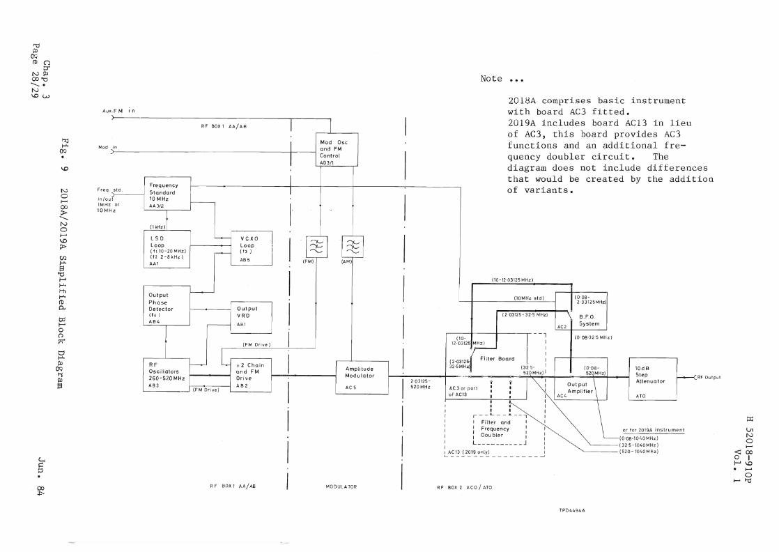
t"dPo>
Q'qro (J
crN~OO~............N\Ow
Aux.F MIn
Note
2018A comprises basic instrumentwith board AC3 fitted.
~
U1N0;--
<000 I~\O
I---ol
0I--A~
RF Output
(32'5-1040MHz)------(520-1040MHz)II . I
!.-A~l': i2~1=-0~1~ -J
)
R F BOX 1 AA/AB I 1in I
Mod Oscand FM
I ControlAD3/1
I I that wou.ld be Creal:.eaFrequency
oy l:ne aa
std. IStandardof variants.
( 10 MHz
I
or I AA3/2.-
zI
I-OkHzJLSD -- V C·XO I
I ILoop Loop
rv:: ~
I~ ~
(fl10-20MHz) r--- (f3 ) "- "-(122-BkHz) AB 5AAl
(FM) (AM)
II
(10-12'03125 MHz)
Outputf--------J
Phase
(10MHz std) (0'08-
Detector Output
I2'03125MHz)
(f4 ) VRD(2'03125- 32·5 MHz)
AB4
IB.F.O.
.-------1 ABl~ System
AC2
I (10- I --i (0 '08-32'5 MHz)
(FM Drive)12'03125 MHz)
L I~
I :RF 1-------1 .;.2 Chain I
(2'03125-Filter Board
Oscillators and FMAmplitude
32·5 MHz) (32'5- I (0'08-520 MHz) I
10dB
260-520 MHz DriveModulator -""",,-
520MHz) Step
AB3 AB2
I I2,03125- i i i1J \ Attenuator
(FM Drive)AC 5 520 MHz AC 3 or part • II
I Output
of AC13 • • I Amplifier
• I I AC4 ATO
I II. I I"
or for 2019A ins tr urru
in/auIMHz10 MH
Freq
t-:tjt-J.Q'Q Mod
\.0 . I '-L ......~b .... "'-4 ............ .....,-..., --- - ----- -~- - es- ~ ,... • 1 _1 ., ~ ..... ion
Noto--'
00~<,Noto--'
\0
>Cf.)J-J.13
todt-J~.
t-hI-'eroA&
OJt-&on~
t:Jt-Je~
00t1PJS
~::J
~R F BOX 1 A A/ AB MODULATOR RF BOX 2 ACO / ATO
TPD4494A