I FordParts - Ford Crash Parts
115
I FordParts.com F-SERIES CREW CAB INSTRUCTION SHEE
Transcript of I FordParts - Ford Crash Parts

I FordParts.com
F-SERIES CREW CAB
INSTRUCTION SHEETS

INSTRUCTIONS FOR ACCESSING BOOKMARKS
1. Open the PDF in Adobe Acrobat Reader.
2. If the “sidebar” is not open as shown on the left, go to“View” in the menu bar and click to expand.
3. Navigate to the “Show/Hide” menu.
4. Navigate to the “Navigation Panes”. Then select the“Bookmarks” pane.
5. You should see a side bar that looks like the imageon this page.
6. To access a specific Instruction Sheet, click on the titlein the list.

CPR © 2014 FORD MOTOR COMPANYDEARBORN, MICHIGAN 48121
10-14
SKFL34-1610696-AA SHEET 1 OF 3
F-SERIES SUPER CAB AND CREW CAB - #3 REAR FLOOR CROSSMEMBER INSTALLATION -
SERVICE KIT INSTRUCTIONS
F-SERIES SUPER CAB AND CREW CAB - #3 REAR FLOOR CROSSMEMBER INSTALLATION - SERVICE KIT INSTRUCTIONS
KIT
Part Number Description Quantity
FL34-1610696-AB #3 Rear Floor Crossmember 1
SKFL34-1610696-AA Instruction Sheet 1
NOT INCLUDED IN KIT (PROCURE LOCALLY)
Part Number Description Quantity
W702512-S900C Blind Rivet 32
W707638-S900C Blind Rivet 28
Motorcraft TA-1, 3M 8115 or Fusor 108B
Metal Panel Bonding Adhesive 1
SERVICE GUIDELINES:
• Aluminumrepairsshouldbeperformedinanareaprotectedfromsteelworkingareas,andtoolsusedin aluminumrepairshouldbequarantinedfromsteelrepairtools. • ReplacementSelf-PiercingRivets(SPRs)arethepreferredreplacementduringrepairfororiginalSPR locations,wherefeasible.BlindrivetsarethenextpreferredreplacementfororiginalSPRs.Insomecases,solid rivetsmayalsobeusedasareplacementforSPRs.Thefigureswillexplicitlycalloutwhichrivetsarepossible. • ReplacementSPRsaretobeinstalledadjacenttooriginalSPRlocation.
NOTE: Do not install replacement SPR in original SPR hole.
• BlindrivetsmaybeinstalledinoriginalSPRholes,aftertheyarereamedoutto6.5mm.Besuretogrindall surfacesoftheflangesmoothpriortoblindrivetinstallationinoriginalSPRlocations.
• FlowDrillScrews(FDS)aretobereplacedbyblindrivetsonly.TheoriginallocationoftheFDSisused,but reamedoutto6.5mm.
• Rivetsmayberemovedbydrilling,grinding,orSPRgunsetupasarivetremovaltool.
• Usingheat(notexceeding425°F)toloosenarivetbondedpanelshouldonlybedonewhenallpanelsinthe jointwillbereplacedorseparatedandnewadhesiveapplied.
• Flangepreparationforadhesiveistogrindtocleanmetalwith80-120grit,clean,andthenapplytheadhesive, spreadingitoutwithanacidbrush,coveringanyexposedaluminum.
• Clecosareanexcellentwaytoholdthepanelsintopositionwhenfittinganddrillingrivetholes.

CPR © 2014 FORD MOTOR COMPANYDEARBORN, MICHIGAN 48121
10-14
SKFL34-1610696-AA SHEET 2 OF 3
F-SERIES SUPER CAB AND CREW CAB - #3 REAR FLOOR CROSSMEMBER INSTALLATION -
SERVICE KIT INSTRUCTIONS
• Blackdotsrepresentthelocationofthetwenty-four(24)blindrivets(W702512-S900C).(RefertoFigure1).
• Blacktrianglerepresentthelocationofthetwenty-eight(28)blindrivets(W707638-S900C)rivetstothefloorpan (RefertoFigure1).
• Crossmembercanbesectionedtorepairoutboardends.(RefertoFigure2).
FIGURE 2
FIGURE 1 (COMMON BETWEEN RIGHT AND LEFT HAND SIDES)
SUGGESTED FOR SECTIONING CUTLINES
CPR © 2014 FORD MOTOR COMPANYDEARBORN, MICHIGAN 48121
10-14
SKFL34-1610696-AA SHEET 3 OF 3
F-SERIES SUPER CAB AND CREW CAB - #3 REAR FLOOR CROSSMEMBER INSTALLATION -
SERVICE KIT INSTRUCTIONS
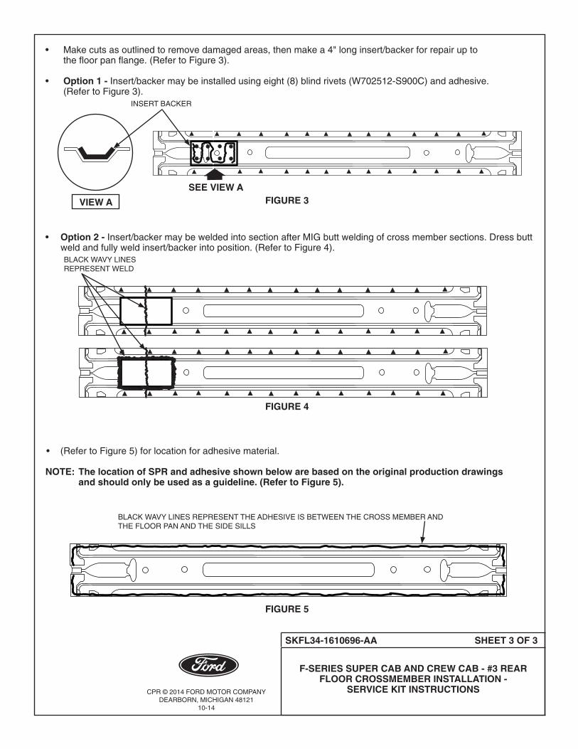
• Makecutsasoutlinedtoremovedamagedareas,thenmakea4"longinsert/backerforrepairupto thefloorpanflange.(RefertoFigure3).
• Option 1 - Insert/backermaybeinstalledusingeight(8)blindrivets(W702512-S900C)andadhesive. (RefertoFigure3).
• Option 2 - Insert/backermaybeweldedintosectionafterMIGbuttweldingofcrossmembersections.Dressbutt weldandfullyweldinsert/backerintoposition.(RefertoFigure4).
• (RefertoFigure5)forlocationforadhesivematerial. NOTE: The location of SPR and adhesive shown below are based on the original production drawings and should only be used as a guideline. (Refer to Figure 5).
FIGURE 5
BLACK WAVY LINES REPRESENT THE ADHESIVE IS BETWEEN THE CROSS MEMBER AND THE FLOOR PAN AND THE SIDE SILLS
FIGURE 3SEE VIEW A
VIEW A
INSERT BACKER
FIGURE 4
BLACK WAVY LINES REPRESENT WELD
CPR © 2014 FORD MOTOR COMPANYDEARBORN, MICHIGAN 48121
10-14
SKFL34-1624358-AA SHEET 1 OF 2
F-SERIES BODY INSTALLATION FOR CREW CAB B-PILLAR INNER -
SERVICE KIT INSTRUCTIONS
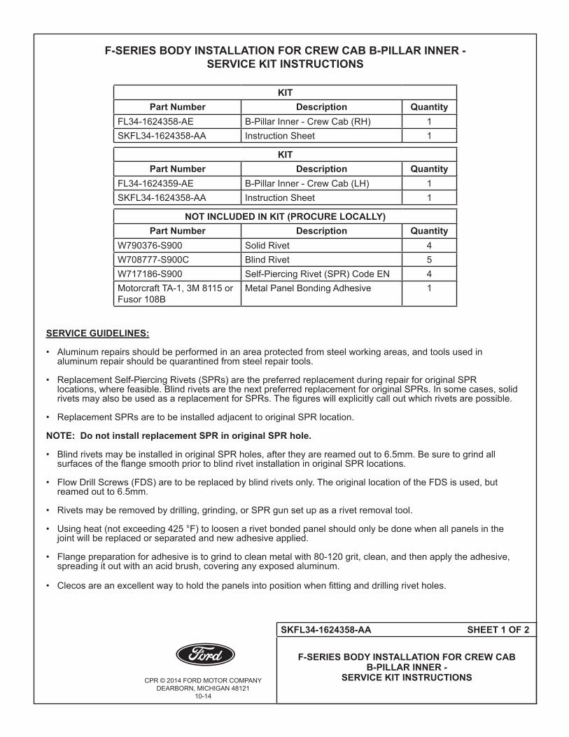
F-SERIES BODY INSTALLATION FOR CREW CAB B-PILLAR INNER - SERVICE KIT INSTRUCTIONS
KITPart Number Description Quantity
FL34-1624358-AE B-Pillar Inner - Crew Cab (RH) 1SKFL34-1624358-AA Instruction Sheet 1
KITPart Number Description Quantity
FL34-1624359-AE B-Pillar Inner - Crew Cab (LH) 1SKFL34-1624358-AA Instruction Sheet 1
NOT INCLUDED IN KIT (PROCURE LOCALLY)Part Number Description Quantity
W790376-S900 Solid Rivet 4W708777-S900C Blind Rivet 5W717186-S900 Self-Piercing Rivet (SPR) Code EN 4Motorcraft TA-1, 3M 8115 or Fusor 108B
Metal Panel Bonding Adhesive 1
SERVICE GUIDELINES:
• Aluminumrepairsshouldbeperformedinanareaprotectedfromsteelworkingareas,andtoolsusedin aluminumrepairshouldbequarantinedfromsteelrepairtools. • ReplacementSelf-PiercingRivets(SPRs)arethepreferredreplacementduringrepairfororiginalSPR locations,wherefeasible.BlindrivetsarethenextpreferredreplacementfororiginalSPRs.Insomecases,solid rivetsmayalsobeusedasareplacementforSPRs.Thefigureswillexplicitlycalloutwhichrivetsarepossible. • ReplacementSPRsaretobeinstalledadjacenttooriginalSPRlocation.
NOTE: Do not install replacement SPR in original SPR hole.
• BlindrivetsmaybeinstalledinoriginalSPRholes,aftertheyarereamedoutto6.5mm.Besuretogrindall surfacesoftheflangesmoothpriortoblindrivetinstallationinoriginalSPRlocations.
• FlowDrillScrews(FDS)aretobereplacedbyblindrivetsonly.TheoriginallocationoftheFDSisused,but reamedoutto6.5mm.
• Rivetsmayberemovedbydrilling,grinding,orSPRgunsetupasarivetremovaltool.
• Usingheat(notexceeding425°F)toloosenarivetbondedpanelshouldonlybedonewhenallpanelsinthe jointwillbereplacedorseparatedandnewadhesiveapplied.
• Flangepreparationforadhesiveistogrindtocleanmetalwith80-120grit,clean,andthenapplytheadhesive, spreadingitoutwithanacidbrush,coveringanyexposedaluminum.
• Clecosareanexcellentwaytoholdthepanelsintopositionwhenfittinganddrillingrivetholes.

CPR © 2014 FORD MOTOR COMPANYDEARBORN, MICHIGAN 48121
10-14
SKFL34-1624358-AA SHEET 2 OF 2
F-SERIES BODY INSTALLATION FOR CREW CAB B-PILLAR INNER -
SERVICE KIT INSTRUCTIONS
• (RefertoFigure1)forlocationforadhesivematerial.
NOTE: The location of SPR and adhesive shown below are based on the original production drawings and should only be used as a guideline.
FIGURE 1
BLACK WAVY LINES REPRESENT THE LOCATION OF THE ADHESIVE MATERIAL
TWO (2)W708777-S900C BLIND RIVETS ONLY
THREE (3) W708777-S437 BLIND RIVETS ONLY FROM SIDE SILL TO B-PILLAR INNER
TWO (2)W717186-S900SPR EN DG11-200/HOR W790376-S900SOLID RIVETONE (1)
W717186-S900SPR EN DG11-200/HOR W790376-S900SOLID RIVET
ONE (1)W717186-S900SPR EN DG11-200/HOR W790376-S900SOLID RIVET
SQUARED NUMBERS ARE PRO SPOT MANDRELS1 SA-0400/SA-04012 SA-0400/SA-0402
1
1
1
CPR © 2014 FORD MOTOR COMPANYDEARBORN, MICHIGAN 48121
10-14
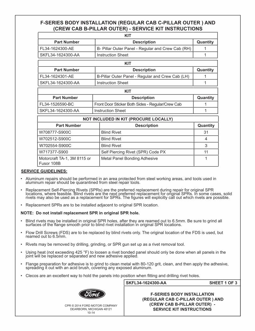
SKFL34-1624300-AA SHEET 1 OF 3
F-SERIES BODY INSTALLATION (REGULAR CAB C-PILLAR OUTER ) AND
(CREW CAB B-PILLAR OUTER) - SERVICE KIT INSTRUCTIONS
F-SERIES BODY INSTALLATION (REGULAR CAB C-PILLAR OUTER ) AND (CREW CAB B-PILLAR OUTER) - SERVICE KIT INSTRUCTIONS
KITPart Number Description Quantity
FL34-1624300-AE B- Pillar Outer Panel - Regular and Crew Cab (RH) 1SKFL34-1624300-AA Instruction Sheet 1
KIT Part Number Description Quantity
FL34-1624301-AE B-Pillar Outer Panel - Regular and Crew Cab (LH) 1SKFL34-1624300-AA Instruction Sheet 1
KITPart Number Description Quantity
FL34-1526590-BC Front Door Sticker Both Sides - Regular/Crew Cab 1SKFL34-1624300-AA Instruction Sheet 1
NOT INCLUDED IN KIT (PROCURE LOCALLY)Part Number Description Quantity
W708777-S900C Blind Rivet 31W702512-S900C Blind Rivet 4W702554-S900C Blind Rivet 3
W717377-S900 Self Piercing Rivet (SPR) Code PX 11Motorcraft TA-1, 3M 8115 or Fusor 108B
Metal Panel Bonding Adhesive 1
SERVICE GUIDELINES:
• Aluminumrepairsshouldbeperformedinanareaprotectedfromsteelworkingareas,andtoolsusedin aluminumrepairshouldbequarantinedfromsteelrepairtools. • ReplacementSelf-PiercingRivets(SPRs)arethepreferredreplacementduringrepairfororiginalSPR locations,wherefeasible.BlindrivetsarethenextpreferredreplacementfororiginalSPRs.Insomecases,solid rivetsmayalsobeusedasareplacementforSPRs.Thefigureswillexplicitlycalloutwhichrivetsarepossible. • ReplacementSPRsaretobeinstalledadjacenttooriginalSPRlocation.
NOTE: Do not install replacement SPR in original SPR hole.
• BlindrivetsmaybeinstalledinoriginalSPRholes,aftertheyarereamedoutto6.5mm.Besuretogrindall surfacesoftheflangesmoothpriortoblindrivetinstallationinoriginalSPRlocations.
• FlowDrillScrews(FDS)aretobereplacedbyblindrivetsonly.TheoriginallocationoftheFDSisused,but reamedoutto6.5mm.
• Rivetsmayberemovedbydrilling,grinding,orSPRgunsetupasarivetremovaltool.
• Usingheat(notexceeding425°F)toloosenarivetbondedpanelshouldonlybedonewhenallpanelsinthe jointwillbereplacedorseparatedandnewadhesiveapplied.
• Flangepreparationforadhesiveistogrindtocleanmetalwith80-120grit,clean,andthenapplytheadhesive, spreadingitoutwithanacidbrush,coveringanyexposedaluminum.
• Clecosareanexcellentwaytoholdthepanelsintopositionwhenfittinganddrillingrivetholes.

CPR © 2014 FORD MOTOR COMPANYDEARBORN, MICHIGAN 48121
10-14
SKFL34-1624300-AA SHEET 2 OF 3
F-SERIES BODY INSTALLATION (REGULAR CAB C-PILLAR OUTER ) AND
(CREW CAB B-PILLAR OUTER) - SERVICE KIT INSTRUCTIONS
• (RefertoFigure2)forlocationforadhesivematerial. NOTE: See Crew Cab door opening panel for associated rivets. NOTE: The location of SPR and adhesive shown below are based on the original production drawings and should only be used as a guideline. (Refer to Figure 2).
FIGURE 1 FIGURE 2
BLACK WAVY LINES REPRESENT THE LOCATION OF THE ADHESIVE MATERIAL
THREE (3)W708777-S900C BLIND RIVETS
FIVE (5) W708777-S900C BLIND RIVETS
B-PILLAR OUTER FOR CREW CAB
TWO (2) W702512-S900C BLIND RIVETS ONLY
CPR © 2014 FORD MOTOR COMPANYDEARBORN, MICHIGAN 48121
10-14
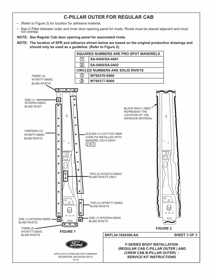
SKFL34-1624300-AA SHEET 3 OF 3
F-SERIES BODY INSTALLATION (REGULAR CAB C-PILLAR OUTER ) AND
(CREW CAB B-PILLAR OUTER) - SERVICE KIT INSTRUCTIONS
• (RefertoFigure2)forlocationforadhesivematerial. •SeeC-Pillarbetweenouterandinnerdooropeningpanelforrivets.Rivetsmustbeplacedadjacentandmust notoverlap. NOTE: See Regular Cab door opening panel for associated rivets. NOTE: The location of SPR and adhesive shown below are based on the original production drawings and should only be used as a guideline. (Refer to Figure 2).
FIGURE 1FIGURE 2
BLACK WAVY LINES REPRESENT THE LOCATION OF THE ADHESIVE MATERIAL
THREE (3) W708777-S900C BLIND RIVETS
THREE (3)W708777-S900C BLIND RIVETS
C-PILLAR OUTER FOR REGULAR CAB
ELEVEN (11) W717337-S900CODE PX INSTALLED WITH MANDREL DG10-200/H
ONE (1)W702554-S900CBLIND RIVET
TWO (2) W708777-S900C BLIND RIVETS
THIRTEEN (13) W708777-S900C BLIND RIVETS
ONE (1) W702554-S900C BLIND RIVETS
ONE (1) W702554-S900C BLIND RIVETS
TWO (2) W702512-S900C BLIND RIVETS ONLY
2
SQUARED NUMBERS ARE PRO SPOT MANDRELS1 SA-0400/SA-04012 SA-0400/SA-0402
CIRCLED NUMBERS ARE SOLID RIVETS1 W790376-S9002 W790377-S900
2

CPR © 2014 FORD MOTOR COMPANYDEARBORN, MICHIGAN 48121
11-14
SKFL34-1540304-AB SHEET 1 OF 3
F-SERIES BODY INSTALLATION FOR BACK PANEL AND REINFORCEMENTS -
SERVICE KIT INSTRUCTIONS FOR ALL CABS
F-SERIES BODY INSTALLATION FOR BACK PANEL AND REINFORCEMENTS - SERVICE KIT INSTRUCTIONS FOR ALL CABS
KITPart Number Description Quantity
FL34-1540304-AB Cab Back Panel 1SKFL34-1540304-AB Instruction Sheet 1
KIT Part Number Description Quantity
FL34-15403E32-AG Back Panel Reinforcement - Regular Cabs Only 1SKFL34-1540304-AB Instruction Sheet 1
KITPart Number Description Quantity
FL34-16403E32-AG Back Panel Reinforcement - Super and Crew Cabs 1SKFL34-1540304-AB Instruction Sheet 1
NOT INCLUDED IN KIT (PROCURE LOCALLY)Part Number Description Quantity
W790376-S900 Solid Rivet 13W790377-S900 Solid Rivet 8W707638-S900C Blind Rivet 43W702512-S900C Blind Rivet 32W708777-S900C Blind Rivet 6W710246-S900 Service Level SPR Rivet Code BN 4W708713-S900 Service Level SPR Rivet Code AS 13W708714-S900 Service Level SPR Rivet Code AT 4Motorcraft TA-1, 3M 8115 or Fusor 108B Metal Panel Bonding Adhesive 1
CPR © 2014 FORD MOTOR COMPANYDEARBORN, MICHIGAN 48121
11-14
SKFL34-1540304-AB SHEET 2 OF 3
F-SERIES BODY INSTALLATION FOR BACK PANEL AND REINFORCEMENTS -
SERVICE KIT INSTRUCTIONS FOR ALL CABS
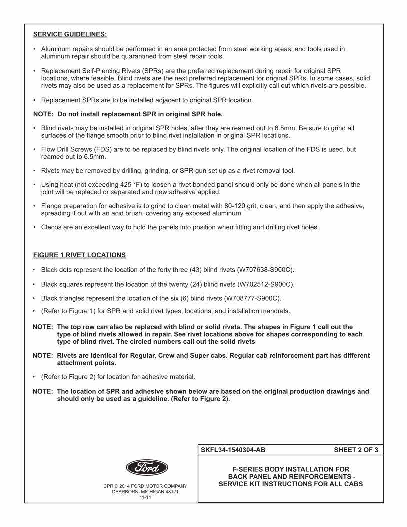
SERVICE GUIDELINES:
• Aluminumrepairsshouldbeperformedinanareaprotectedfromsteelworkingareas,andtoolsusedin aluminum repair should be quarantined from steel repair tools. • ReplacementSelf-PiercingRivets(SPRs)arethepreferredreplacementduringrepairfororiginalSPR locations, where feasible. Blind rivets are the next preferred replacement for original SPRs. In some cases, solid rivetsmayalsobeusedasareplacementforSPRs.Thefigureswillexplicitlycalloutwhichrivetsarepossible. • ReplacementSPRsaretobeinstalledadjacenttooriginalSPRlocation.
NOTE: Do not install replacement SPR in original SPR hole.
• BlindrivetsmaybeinstalledinoriginalSPRholes,aftertheyarereamedoutto6.5mm.Besuretogrindall surfacesoftheflangesmoothpriortoblindrivetinstallationinoriginalSPRlocations.
• FlowDrillScrews(FDS)aretobereplacedbyblindrivetsonly.TheoriginallocationoftheFDSisused,but reamed out to 6.5mm.
• Rivetsmayberemovedbydrilling,grinding,orSPRgunsetupasarivetremovaltool.
• Usingheat(notexceeding425°F)toloosenarivetbondedpanelshouldonlybedonewhenallpanelsinthe jointwillbereplacedorseparatedandnewadhesiveapplied.
• Flangepreparationforadhesiveistogrindtocleanmetalwith80-120grit,clean,andthenapplytheadhesive, spreading it out with an acid brush, covering any exposed aluminum.
• Clecosareanexcellentwaytoholdthepanelsintopositionwhenfittinganddrillingrivetholes.
FIGURE 1 RIVET LOCATIONS
• Blackdotsrepresentthelocationofthefortythree(43)blindrivets(W707638-S900C).
• Blacksquaresrepresentthelocationofthetwenty(24)blindrivets(W702512-S900C).
• Blacktrianglesrepresentthelocationofthesix(6)blindrivets(W708777-S900C).
• (RefertoFigure1)forSPRandsolidrivettypes,locations,andinstallationmandrels. NOTE: The top row can also be replaced with blind or solid rivets. The shapes in Figure 1 call out the type of blind rivets allowed in repair. See rivet locations above for shapes corresponding to each type of blind rivet. The circled numbers call out the solid rivets
NOTE: Rivets are identical for Regular, Crew and Super cabs. Regular cab reinforcement part has different attachment points.
• (RefertoFigure2)forlocationforadhesivematerial. NOTE: The location of SPR and adhesive shown below are based on the original production drawings and should only be used as a guideline. (Refer to Figure 2).
CPR © 2014 FORD MOTOR COMPANYDEARBORN, MICHIGAN 48121
11-14
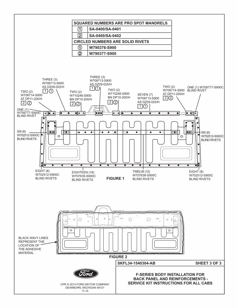
SKFL34-1540304-AB SHEET 3 OF 3
F-SERIES BODY INSTALLATION FOR BACK PANEL AND REINFORCEMENTS -
SERVICE KIT INSTRUCTIONS FOR ALL CABS
FIGURE 1
FIGURE 2
BLACK WAVY LINES REPRESENT THE LOCATION OF THE ADHESIVE MATERIAL
TWO(2)W708714-S900AT DP11-200/H
EIGHTEEN(18)W707638-S900C BLIND RIVETS
EIGHT(8)W702512-S900C BLIND RIVETS
SIX(6)W702512-S900C BLIND RIVETS
EIGHT(8)W702512-S900C BLIND RIVETS
TWO(2)W710246-S900BN DP10-200/H
THREE(3)W708713-S900 AS DZ09-025/H
TWO(2)W710246-S900BN DP10-200/H
SEVEN(7)W708713-S900 AS DZ09-025/H
TWO(2)W708714-S900AT DP11-200/H
ONE(1)W708777-S900CBLIND RIVET
ONE(1)W708777-S900CBLIND RIVET
THREE(3)W708713-S900AS DZ09-025/H
TWELVE(12)W707638-S900C BLIND RIVETS
SIX(6)W702512-S900C BLIND RIVETS
2
1
2
1
21
2
SQUARED NUMBERS ARE PRO SPOT MANDRELS1 SA-0400/SA-04012 SA-0400/SA-0402
CIRCLED NUMBERS ARE SOLID RIVETS1 W790376-S9002 W790377-S900
2
1
2
1
21
2

CPR © 2014 FORD MOTOR COMPANYDEARBORN, MICHIGAN 48121
10-14
SKFL34-1501610-AA SHEET 1 OF 3
F-SERIES DASH PANEL INSTALLATION - SERVICE KIT INSTRUCTIONS FOR ALL CABS
F-SERIES BODY DASH PANEL INSTALLATION - SERVICE KIT INSTRUCTIONS FOR ALL CABS
KIT Part Number Description Quantity
FL34-1501610-AJ Dash Panel Assembly 1SKFL34-1501610-AA Instruction Sheet 1
NOT INCLUDED IN KIT (PROCURE LOCALLY)Part Number Description Quantity
W707638-S900C Blind Rivet 49W708777-S900C Blind Rivet 30W702554-S900C Blind Rivet 6Motorcraft TA-1, 3M 8115 or Fusor 108B
Metal Panel Bonding Adhesive 1
SERVICE GUIDELINES:
• Aluminumrepairsshouldbeperformedinanareaprotectedfromsteelworkingareas,andtoolsusedin aluminumrepairshouldbequarantinedfromsteelrepairtools. • ReplacementSelf-PiercingRivets(SPRs)arethepreferredreplacementduringrepairfororiginalSPR locations,wherefeasible.BlindrivetsarethenextpreferredreplacementfororiginalSPRs.Insomecases,solid rivetsmayalsobeusedasareplacementforSPRs.Thefigureswillexplicitlycalloutwhichrivetsarepossible. • ReplacementSPRsaretobeinstalledadjacenttooriginalSPRlocation.
NOTE: Do not install replacement SPR in original SPR hole.
• BlindrivetsmaybeinstalledinoriginalSPRholes,aftertheyarereamedoutto6.5mm.Besuretogrindall surfacesoftheflangesmoothpriortoblindrivetinstallationinoriginalSPRlocations.
• FlowDrillScrews(FDS)aretobereplacedbyblindrivetsonly.TheoriginallocationoftheFDSisused,but reamedoutto6.5mm.
• Rivetsmayberemovedbydrilling,grinding,orSPRgunsetupasarivetremovaltool.
• Usingheat(notexceeding425°F)toloosenarivetbondedpanelshouldonlybedonewhenallpanelsinthe jointwillbereplacedorseparatedandnewadhesiveapplied.
• Flangepreparationforadhesiveistogrindtocleanmetalwith80-120grit,clean,andthenapplytheadhesive, spreadingitoutwithanacidbrush,coveringanyexposedaluminum.
• Clecosareanexcellentwaytoholdthepanelsintopositionwhenfittinganddrillingrivetholes.
CPR © 2014 FORD MOTOR COMPANYDEARBORN, MICHIGAN 48121
10-14
SKFL34-1501610-AA SHEET 2 OF 3
F-SERIES DASH PANEL INSTALLATION - SERVICE KIT INSTRUCTIONS FOR ALL CABS
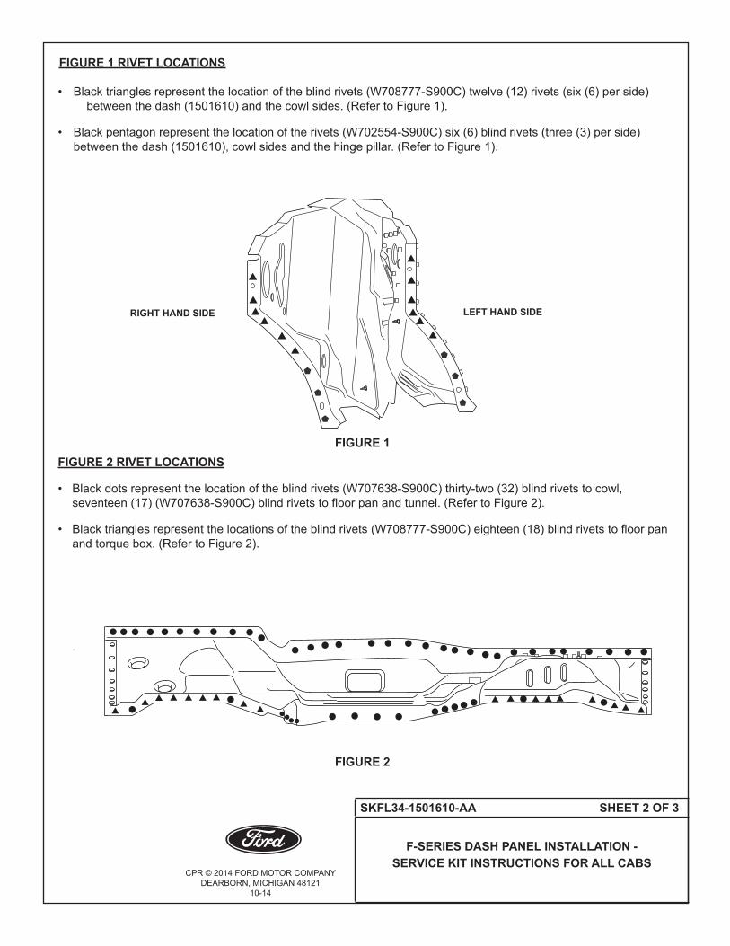
FIGURE 1 RIVET LOCATIONS • Blacktrianglesrepresentthelocationoftheblindrivets(W708777-S900C)twelve(12)rivets(six(6)perside) betweenthedash(1501610)andthecowlsides.(RefertoFigure1). • Blackpentagonrepresentthelocationoftherivets(W702554-S900C)six(6)blindrivets(three(3)perside) betweenthedash(1501610),cowlsidesandthehingepillar.(RefertoFigure1).
FIGURE 2 RIVET LOCATIONS
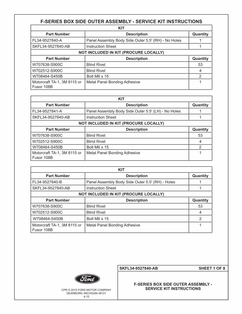
• Blackdotsrepresentthelocationoftheblindrivets(W707638-S900C)thirty-two(32)blindrivetstocowl, seventeen(17)(W707638-S900C)blindrivetstofloorpanandtunnel.(RefertoFigure2). • Blacktrianglesrepresentthelocationsoftheblindrivets(W708777-S900C)eighteen(18)blindrivetstofloorpan andtorquebox.(RefertoFigure2).
FIGURE 1
FIGURE 2
RIGHT HAND SIDE LEFT HAND SIDE

CPR © 2014 FORD MOTOR COMPANYDEARBORN, MICHIGAN 48121
10-14
SKFL34-1501610-AA SHEET 3 OF 3
F-SERIES DASH PANEL INSTALLATION - SERVICE KIT INSTRUCTIONS FOR ALL CABS
• Wavylinesrepresentthelocationoftheadhesivematerialbetweenthedashandthecowlsides. (RefertoFigure3).
NOTE: The location of SPR and adhesive shown below are based on the original production drawings and should only be used as a guideline. (Refer to Figure 3).
• Wavylinesrepresentthelocationoftheadhesivematerialbetweenthedashpanelandthecowlinner,thefloorpan andthetunnel(1511170).(RefertoFigure4).
NOTE: The location of SPR and adhesive shown below are based on the original production drawings and should only be used as a guideline. (Refer to Figure 4).
FIGURE 3
RIGHT HAND SIDELEFT HAND SIDE
BLACK WAVY LINES REPRESENT THE LOCATION OF THE ADHESIVE MATERIAL
FIGURE 4
BLACK WAVY LINES REPRESENT THE LOCATION OF THE ADHESIVE MATERIAL

CPR © 2014 FORD MOTOR COMPANYDEARBORN, MICHIGAN 48121
10-14
SKFL34-9900124-AA SHEET 1 OF 2
F-SERIES BOX FRONT PANEL ASSEMBLY - SERVICE KIT INSTRUCTIONS
F-SERIES BOX FRONT PANEL ASSEMBLY - SERVICE KIT INSTRUCTIONS
KITPart Number Description Quantity
FL34-9900124-AF Box Front Panel (RH) 1SKFL34-9900124-AA Instruction Sheet 1
KITPart Number Description Quantity
FL34-9900374-AD Box Fill Panel (RH) 1
SKFL34-9900124-AA Instruction Sheet 1
KIT Part Number Description Quantity
FL34-9900375-AD Box Fill Panel (LH) 1
SKFL34-9900124-AA Instruction Sheet 1
NOT INCLUDED IN KIT (PROCURE LOCALLY)Part Number Description Quantity
W707638-S900C Blind Rivet 34W702512-S900C Blind Rivet 8W708777-S900C Blind Rivet 4Motorcraft TA-1, 3M 8115 or Fusor 108B
Metal Panel Bonding Adhesive 1
SERVICE GUIDELINES: • Aluminumrepairsshouldbeperformedinanareaprotectedfromsteelworkingareas,andtoolsusedin aluminumrepairshouldbequarantinedfromsteelrepairtools. • ReplacementSelf-PiercingRivets(SPRs)arethepreferredreplacementduringrepairfororiginalSPR locations,wherefeasible.BlindrivetsarethenextpreferredreplacementfororiginalSPRs.Insomecases,solid rivetsmayalsobeusedasareplacementforSPRs.Thefigureswillexplicitlycalloutwhichrivetsarepossible. • ReplacementSPRsaretobeinstalledadjacenttooriginalSPRlocation.
NOTE: Do not install replacement SPR in original SPR hole.
• BlindrivetsmaybeinstalledinoriginalSPRholes,aftertheyarereamedoutto6.5mm.Besuretogrindall surfacesoftheflangesmoothpriortoblindrivetinstallationinoriginalSPRlocations.
• FlowDrillScrews(FDS)aretobereplacedbyblindrivetsonly.TheoriginallocationoftheFDSisused,but reamedoutto6.5mm.
• Rivetsmayberemovedbydrilling,grinding,orSPRgunsetupasarivetremovaltool.
• Usingheat(notexceeding425°F)toloosenarivetbondedpanelshouldonlybedonewhenallpanelsinthe jointwillbereplacedorseparatedandnewadhesiveapplied.
• Flangepreparationforadhesiveistogrindtocleanmetalwith80-120grit,clean,andthenapplytheadhesive, spreadingitoutwithanacidbrush,coveringanyexposedaluminum.
• Clecosareanexcellentwaytoholdthepanelsintopositionwhenfittinganddrillingrivetholes.

CPR © 2014 FORD MOTOR COMPANYDEARBORN, MICHIGAN 48121
10-14
SKFL34-9900124-AA SHEET 2 OF 2
F-SERIES BOX FRONT PANEL ASSEMBLY - SERVICE KIT INSTRUCTIONS
FIGURE 1 RIVET LOCATIONS
• Blackdotsrepresentthelocationofnine(9)blindrivets(W707638-S900C).(RefertoFigure1).
• Blacksquaresrepresentthelocationoffour(4)blindrivets(W702512-S900C).(RefertoFigure1).
• Blacktrianglesrepresentthelocationofone(1)blindrivets(W708777-S900C).(RefertoFigure1).
• Blackdotsrepresentthelocationofthirteen(13)blindrivets(W707638-S900C).(RefertoFigure2).
FIGURE 1
NOTE: THESE THREE (3) RIVETS TO BE SHOT DIRECTIONALLY FROM INSIDE OF BED.
FIGURE 2
5.5' BOX 6.5' AND 8.0' BOX
NOTE: THESE FOUR (4) RIVETS TO BE SHOT DIRECTIONALLY FROM INSIDE OF BED.

CPR © 2014 FORD MOTOR COMPANYDEARBORN, MICHIGAN 48121
10-14
SKFL34-9941058-AA SHEET 1 OF 3
F-SERIES BOX REAR CORNER PILLAR ASSEMBLY - SERVICE KIT INSTRUCTIONS
F-SERIES BOX REAR CORNER PILLAR ASSEMBLY - SERVICE KIT INSTRUCTIONSKIT
Part Number Description QuantityFL34-9941058-AF Box Rear Pillar Assembly Rear Corner Outer (RH) 1SKFL34-9941058-AA Instruction Sheet 1
KITPart Number Description Quantity
FL34-9941059-AF Box Rear Pillar Assembly Rear Corner Outer (LH) 1SKFL34-9941058-AA Instruction Sheet 1
KITPart Number Description Quantity
FL34-9941032-AM Box Rear Pillar Assembly Rear Corner Inner (RH) 1SKFL34-9941058-AA Instruction Sheet 1
KITPart Number Description Quantity
FL34-9941033-AK Box Rear Pillar Assembly Rear Corner Inner (LH) 1SKFL34-9941058-AA Instruction Sheet 1
NOT INCLUDED IN KIT (PROCURE LOCALLY)Part Number Description Quantity
W707638-S900C Blind Rivet 10W702512-S900C Blind Rivet 18W708777-S900C Blind Rivet 5W702554-S900C Blind Rivet 4Motorcraft TA-1, 3M 8115 or Fusor 108B
Metal Panel Bonding Adhesive 1

CPR © 2014 FORD MOTOR COMPANYDEARBORN, MICHIGAN 48121
10-14
SKFL34-9941058-AA SHEET 2 OF 3
F-SERIES BOX REAR CORNER PILLAR ASSEMBLY - SERVICE KIT INSTRUCTIONS
SERVICE GUIDELINES:
• Aluminumrepairsshouldbeperformedinanareaprotectedfromsteelworkingareas,andtoolsusedin aluminumrepairshouldbequarantinedfromsteelrepairtools. • ReplacementSelf-PiercingRivets(SPRs)arethepreferredreplacementduringrepairfororiginalSPR locations,wherefeasible.BlindrivetsarethenextpreferredreplacementfororiginalSPRs.Insomecases,solid rivetsmayalsobeusedasareplacementforSPRs.Thefigureswillexplicitlycalloutwhichrivetsarepossible. • ReplacementSPRsaretobeinstalledadjacenttooriginalSPRlocation.
NOTE: Do not install replacement SPR in original SPR hole.
• BlindrivetsmaybeinstalledinoriginalSPRholes,aftertheyarereamedoutto6.5mm.Besuretogrindall surfacesoftheflangesmoothpriortoblindrivetinstallationinoriginalSPRlocations.
• FlowDrillScrews(FDS)aretobereplacedbyblindrivetsonly.TheoriginallocationoftheFDSisused,but reamedoutto6.5mm.
• Rivetsmayberemovedbydrilling,grinding,orSPRgunsetupasarivetremovaltool.
• Usingheat(notexceeding425°F)toloosenarivetbondedpanelshouldonlybedonewhenallpanelsinthe jointwillbereplacedorseparatedandnewadhesiveapplied.
• Flangepreparationforadhesiveistogrindtocleanmetalwith80-120grit,clean,andthenapplytheadhesive, spreadingitoutwithanacidbrush,coveringanyexposedaluminum.
• Clecosareanexcellentwaytoholdthepanelsintopositionwhenfittinganddrillingrivetholes.
FIGURE 1 RIVET LOCATIONS
• Blacktrianglesrepresentthelocationoftwo(2)blindrivets(W708777-S900C).(RefertoFigure1).
• Blacksquaresrepresentthelocationofthree(3)rivets(W702512-S900C).(RefertoFigure1).
• Blackpentagonsrepresentthelocationoffour(4)rivets(W702554-S900C).(RefertoFigure1).
FIGURE 1
NOTE: REQUIRES REMOVAL OF FL34-9941058/9-A FOR SERVICING.

CPR © 2014 FORD MOTOR COMPANYDEARBORN, MICHIGAN 48121
10-14
SKFL34-9941058-AA SHEET 3 OF 3
F-SERIES BOX REAR CORNER PILLAR ASSEMBLY - SERVICE KIT INSTRUCTIONS
FIGURE 1 RIVET LOCATIONS
• Blackdotsrepresentthelocationoffive(5)blindrivets(W707638-S900C).(RefertoFigure2).
• Blacktrianglesrepresentthelocationofthree(3)blindrivets(W708777-S900C).(RefertoFigure2). • Blacksquaresrepresentthelocationoffour(4)rivets(W702512-S900C).(RefertoFigure1).
FIGURE 1 RIVET LOCATIONS
a. Blackdotsrepresentthelocationoffive(5)blindrivets(W707638-S900C).(RefertoFigure3).
b.Blacksquaresrepresentthelocationofeleven(11)rivets(W702512-S900C).(RefertoFigure3).
FIGURE 2
FIGURE 3
NOTE: REQUIRES REMOVAL OF FL34-9941058/9-A FOR SERVICING.
CPR © 2015 FORD MOTOR COMPANYDEARBORN, MICHIGAN 48121
4-15
SKFL34-9527840-AB SHEET 1 OF 8
F-SERIES BOX SIDE OUTER ASSEMBLY - SERVICE KIT INSTRUCTIONS
F-SERIES BOX SIDE OUTER ASSEMBLY - SERVICE KIT INSTRUCTIONSKIT
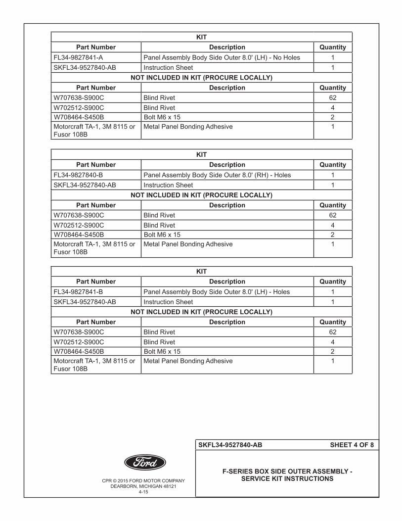
Part Number Description QuantityFL34-9527840-A Panel Assembly Body Side Outer 5.5' (RH) - No Holes 1SKFL34-9527840-AB Instruction Sheet 1
NOT INCLUDED IN KIT (PROCURE LOCALLY)Part Number Description Quantity
W707638-S900C Blind Rivet 53W702512-S900C Blind Rivet 4W708464-S450B Bolt M6 x 15 2Motorcraft TA-1, 3M 8115 or Fusor 108B
Metal Panel Bonding Adhesive 1
KIT Part Number Description Quantity
FL34-9527841-A Panel Assembly Body Side Outer 5.5' (LH) - No Holes 1SKFL34-9527840-AB Instruction Sheet 1
NOT INCLUDED IN KIT (PROCURE LOCALLY)Part Number Description Quantity
W707638-S900C Blind Rivet 53W702512-S900C Blind Rivet 4W708464-S450B Bolt M6 x 15 2Motorcraft TA-1, 3M 8115 or Fusor 108B
Metal Panel Bonding Adhesive 1
KIT Part Number Description Quantity
FL34-9527840-B Panel Assembly Body Side Outer 5.5' (RH) - Holes 1SKFL34-9527840-AB Instruction Sheet 1
NOT INCLUDED IN KIT (PROCURE LOCALLY)Part Number Description Quantity
W707638-S900C Blind Rivet 53W702512-S900C Blind Rivet 4W708464-S450B Bolt M6 x 15 2Motorcraft TA-1, 3M 8115 or Fusor 108B
Metal Panel Bonding Adhesive 1

CPR © 2015 FORD MOTOR COMPANYDEARBORN, MICHIGAN 48121
4-15
SKFL34-9527840-AB SHEET 2 OF 8
F-SERIES BOX SIDE OUTER ASSEMBLY - SERVICE KIT INSTRUCTIONS
KITPart Number Description Quantity
FL34-9527841-B Panel Assembly Body Side Outer 5.5' (LH) - Holes 1SKFL34-9527840-AB Instruction Sheet 1
NOT INCLUDED IN KIT (PROCURE LOCALLY)Part Number Description Quantity
W707638-S900C Blind Rivet 53W702512-S900C Blind Rivet 4W708464-S450B Bolt M6 x 15 2Motorcraft TA-1, 3M 8115 or Fusor 108B
Metal Panel Bonding Adhesive 1
KIT Part Number Description Quantity
FL34-9627840-A Panel Assembly Body Side Outer 6.5' (RH) - No Holes 1
SKFL34-9527840-AB Instruction Sheet 1NOT INCLUDED IN KIT (PROCURE LOCALLY)
Part Number Description QuantityW707638-S900C Blind Rivet 57W702512-S900C Blind Rivet 4W708464-S450B Bolt M6 x 15 2Motorcraft TA-1, 3M 8115 or Fusor 108B
Metal Panel Bonding Adhesive 1
KITPart Number Description Quantity
FL34-9627841-A Panel Assembly Body Side Outer 6.5' (LH) - No Holes 1SKFL34-9527840-AB Instruction Sheet 1
NOT INCLUDED IN KIT (PROCURE LOCALLY)Part Number Description Quantity
W707638-S900C Blind Rivet 57W702512-S900C Blind Rivet 4W708464-S450B Bolt M6 x 15 2Motorcraft TA-1, 3M 8115 or Fusor 108B
Metal Panel Bonding Adhesive 1

CPR © 2015 FORD MOTOR COMPANYDEARBORN, MICHIGAN 48121
4-15
SKFL34-9527840-AB SHEET 3 OF 8
F-SERIES BOX SIDE OUTER ASSEMBLY - SERVICE KIT INSTRUCTIONS
KITPart Number Description Quantity
FL34-9627840-B Panel Assembly Body Side Outer 6.5' (RH) - Holes 1SKFL34-9527840-AB Instruction Sheet 1
NOT INCLUDED IN KIT (PROCURE LOCALLY)Part Number Description Quantity
W707638-S900C Blind Rivet 57W702512-S900C Blind Rivet 4W708464-S450B Bolt M6 x 15 2Motorcraft TA-1, 3M 8115 or Fusor 108B
Metal Panel Bonding Adhesive 1
KIT Part Number Description Quantity
FL34-9627841-B Panel Assembly Body Side Outer 6.5' (LH) - Holes 1
SKFL34-9527840-AB Instruction Sheet 1NOT INCLUDED IN KIT (PROCURE LOCALLY)
Part Number Description QuantityW707638-S900C Blind Rivet 57W702512-S900C Blind Rivet 4W708464-S450B Bolt M6 x 15 2Motorcraft TA-1, 3M 8115 or Fusor 108B
Metal Panel Bonding Adhesive 1
KITPart Number Description Quantity
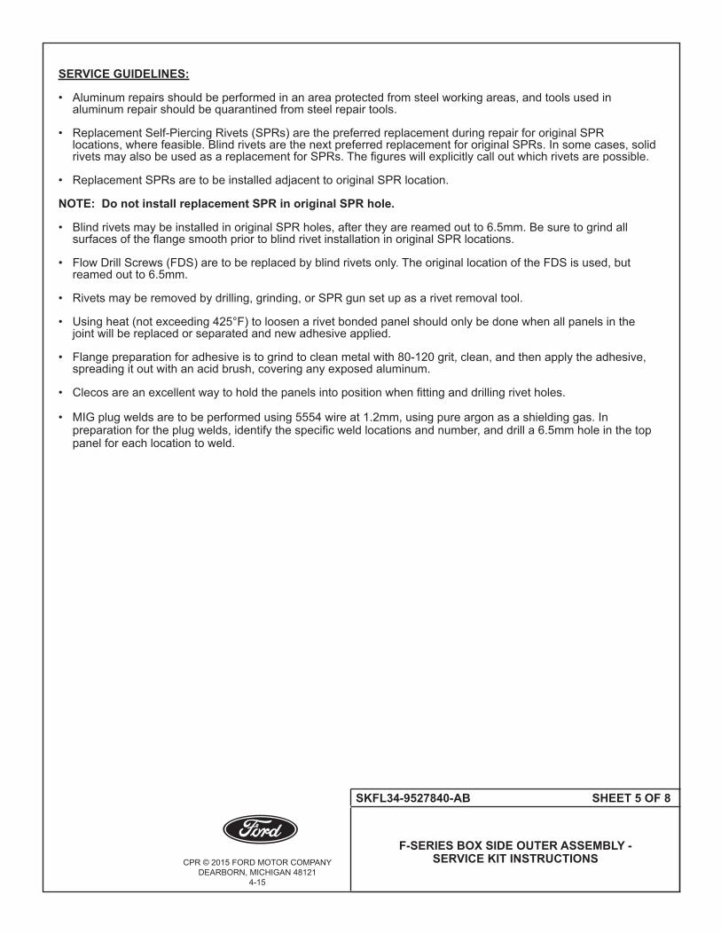
FL34-9827840-A Panel Assembly Body Side Outer 8.0' (RH) - No Holes 1SKFL34-9527840-AB Instruction Sheet 1
NOT INCLUDED IN KIT (PROCURE LOCALLY)Part Number Description Quantity
W707638-S900C Blind Rivet 62W702512-S900C Blind Rivet 4W708464-S450B Bolt M6 x 15 2Motorcraft TA-1, 3M 8115 or Fusor 108B
Metal Panel Bonding Adhesive 1
CPR © 2015 FORD MOTOR COMPANYDEARBORN, MICHIGAN 48121
4-15
SKFL34-9527840-AB SHEET 4 OF 8
F-SERIES BOX SIDE OUTER ASSEMBLY - SERVICE KIT INSTRUCTIONS
KITPart Number Description Quantity
FL34-9827841-A Panel Assembly Body Side Outer 8.0' (LH) - No Holes 1SKFL34-9527840-AB Instruction Sheet 1
NOT INCLUDED IN KIT (PROCURE LOCALLY)Part Number Description Quantity
W707638-S900C Blind Rivet 62W702512-S900C Blind Rivet 4W708464-S450B Bolt M6 x 15 2Motorcraft TA-1, 3M 8115 or Fusor 108B
Metal Panel Bonding Adhesive 1
KITPart Number Description Quantity
FL34-9827840-B Panel Assembly Body Side Outer 8.0' (RH) - Holes 1SKFL34-9527840-AB Instruction Sheet 1
NOT INCLUDED IN KIT (PROCURE LOCALLY)Part Number Description Quantity
W707638-S900C Blind Rivet 62W702512-S900C Blind Rivet 4W708464-S450B Bolt M6 x 15 2Motorcraft TA-1, 3M 8115 or Fusor 108B
Metal Panel Bonding Adhesive 1
KITPart Number Description Quantity
FL34-9827841-B Panel Assembly Body Side Outer 8.0' (LH) - Holes 1SKFL34-9527840-AB Instruction Sheet 1
NOT INCLUDED IN KIT (PROCURE LOCALLY)Part Number Description Quantity
W707638-S900C Blind Rivet 62W702512-S900C Blind Rivet 4W708464-S450B Bolt M6 x 15 2Motorcraft TA-1, 3M 8115 or Fusor 108B
Metal Panel Bonding Adhesive 1
CPR © 2015 FORD MOTOR COMPANYDEARBORN, MICHIGAN 48121
4-15
SKFL34-9527840-AB SHEET 5 OF 8
F-SERIES BOX SIDE OUTER ASSEMBLY - SERVICE KIT INSTRUCTIONS
SERVICE GUIDELINES:
• Aluminumrepairsshouldbeperformedinanareaprotectedfromsteelworkingareas,andtoolsusedin aluminumrepairshouldbequarantinedfromsteelrepairtools. • ReplacementSelf-PiercingRivets(SPRs)arethepreferredreplacementduringrepairfororiginalSPR locations,wherefeasible.BlindrivetsarethenextpreferredreplacementfororiginalSPRs.Insomecases,solid rivetsmayalsobeusedasareplacementforSPRs.Thefigureswillexplicitlycalloutwhichrivetsarepossible. • ReplacementSPRsaretobeinstalledadjacenttooriginalSPRlocation.
NOTE: Do not install replacement SPR in original SPR hole.
• BlindrivetsmaybeinstalledinoriginalSPRholes,aftertheyarereamedoutto6.5mm.Besuretogrindall surfacesoftheflangesmoothpriortoblindrivetinstallationinoriginalSPRlocations.
• FlowDrillScrews(FDS)aretobereplacedbyblindrivetsonly.TheoriginallocationoftheFDSisused,but reamed out to 6.5mm.
• Rivetsmayberemovedbydrilling,grinding,orSPRgunsetupasarivetremovaltool.
• Usingheat(notexceeding425°F)toloosenarivetbondedpanelshouldonlybedonewhenallpanelsinthe jointwillbereplacedorseparatedandnewadhesiveapplied.
• Flangepreparationforadhesiveistogrindtocleanmetalwith80-120grit,clean,andthenapplytheadhesive, spreadingitoutwithanacidbrush,coveringanyexposedaluminum.
• Clecosareanexcellentwaytoholdthepanelsintopositionwhenfittinganddrillingrivetholes.
• MIGplugweldsaretobeperformedusing5554wireat1.2mm,usingpureargonasashieldinggas.In preparationfortheplugwelds,identifythespecificweldlocationsandnumber,anddrilla6.5mmholeinthetop panelforeachlocationtoweld.

CPR © 2015 FORD MOTOR COMPANYDEARBORN, MICHIGAN 48121
4-15
SKFL34-9527840-AB SHEET 6 OF 8
F-SERIES BOX SIDE OUTER ASSEMBLY - SERVICE KIT INSTRUCTIONS
FIGURE 1 RIVET LOCATIONS
• Blackdotsrepresentthelocationofeleven(11)blindrivets(W707638-S900C)orMIGplugwelds.(RefertoFigure1).
• Blacksquaresrepresentthelocationoftwo(2)rivets(W702512-S900C)orMIGplugwelds.(RefertoFigure1).
FIGURE 2 RIVET LOCATIONS
• Blackdotsrepresentthelocationofblindrivets(W707638-S900C)orMIGplugwelds.(Refer to Figure 2). •5.5footboxeighteen(17)blindrivets(W707638-S900C)orMIGplugwelds. •6.5footboxtwenty-two(21)blindrivets(W707638-S900C)orMIGplugwelds. •8.0footboxtwenty-six(26)blindrivets(W707638-S900C)orMIGplugwelds.
• Blackpentagonrepresentfastener(W708464-S450B). (Refer to Figure 2).
FIGURE 26.5' BOX SHOWN
FIGURE 1
ELEVEN (11)W707638-S900CBLIND RIVETSORMIGPLUGWELDS
TWO (2)W702512-S900CBLIND RIVETSORMIGPLUGWELDS

CPR © 2015 FORD MOTOR COMPANYDEARBORN, MICHIGAN 48121
4-15
SKFL34-9527840-AB SHEET 7 OF 8
F-SERIES BOX SIDE OUTER ASSEMBLY - SERVICE KIT INSTRUCTIONS
FIGURE 3 RIVET LOCATIONS
• Blackdotsrepresentthelocationofeleven(10)blindrivets(W707638-S900C)orMIGplugwelds.(RefertoFigure3).
• Blacksquaresrepresentthelocationoftwo(2)rivets(W702512-S900C)orMIGplugwelds.(RefertoFigure3).
• Blackpentagonrepresentthelocationofone(1)fastener(W708464-S450B).(RefertoFigure3).
FIGURE 4 RIVET LOCATIONS
• Blackdotsrepresentthelocationofsixteen(15)blindrivets(W707638-S900C)orMIGplugwelds.(RefertoFigure4).
FIGURE 4
FIGURE 3
FRONT OFVEHICLE
CPR © 2015 FORD MOTOR COMPANYDEARBORN, MICHIGAN 48121
4-15
SKFL34-9527840-AB SHEET 8 OF 8
F-SERIES BOX SIDE OUTER ASSEMBLY - SERVICE KIT INSTRUCTIONS
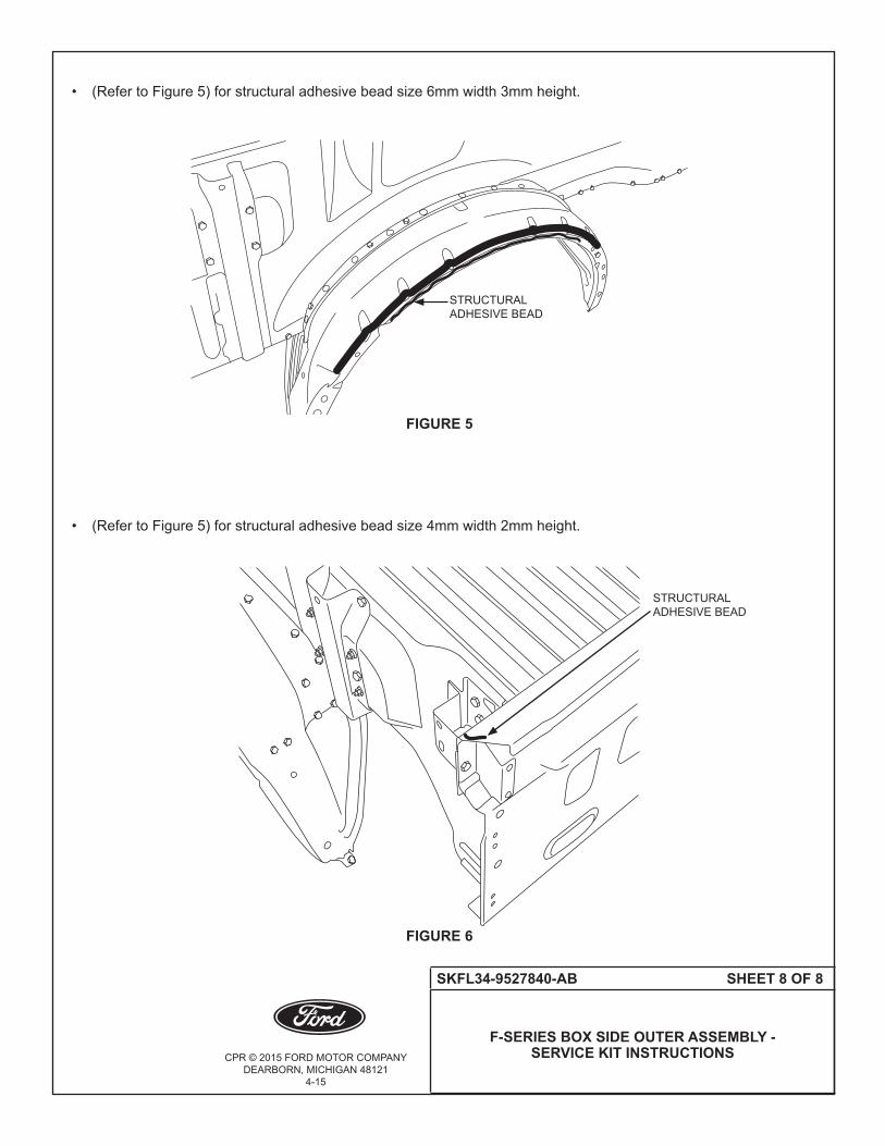
• (RefertoFigure5)forstructuraladhesivebeadsize6mmwidth3mmheight.
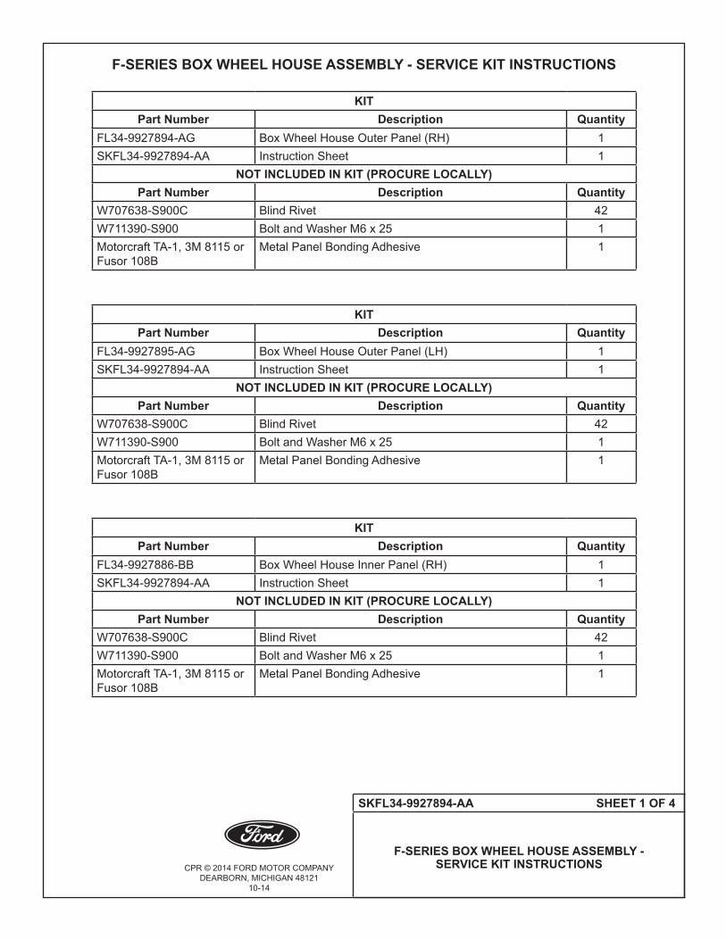
• (RefertoFigure5)forstructuraladhesivebeadsize4mmwidth2mmheight.
FIGURE 6
STRUCTURALADHESIVE BEAD
FIGURE 5
STRUCTURALADHESIVE BEAD
CPR © 2014 FORD MOTOR COMPANYDEARBORN, MICHIGAN 48121
10-14
SKFL34-9927894-AA SHEET 1 OF 4
F-SERIES BOX WHEEL HOUSE ASSEMBLY - SERVICE KIT INSTRUCTIONS
F-SERIES BOX WHEEL HOUSE ASSEMBLY - SERVICE KIT INSTRUCTIONS
KIT Part Number Description Quantity
FL34-9927894-AG Box Wheel House Outer Panel (RH) 1SKFL34-9927894-AA Instruction Sheet 1
NOT INCLUDED IN KIT (PROCURE LOCALLY)Part Number Description Quantity
W707638-S900C Blind Rivet 42W711390-S900 Bolt and Washer M6 x 25 1Motorcraft TA-1, 3M 8115 or Fusor 108B
Metal Panel Bonding Adhesive 1
KIT Part Number Description Quantity
FL34-9927895-AG Box Wheel House Outer Panel (LH) 1SKFL34-9927894-AA Instruction Sheet 1
NOT INCLUDED IN KIT (PROCURE LOCALLY)Part Number Description Quantity
W707638-S900C Blind Rivet 42W711390-S900 Bolt and Washer M6 x 25 1Motorcraft TA-1, 3M 8115 or Fusor 108B
Metal Panel Bonding Adhesive 1
KITPart Number Description Quantity
FL34-9927886-BB Box Wheel House Inner Panel (RH) 1SKFL34-9927894-AA Instruction Sheet 1
NOT INCLUDED IN KIT (PROCURE LOCALLY)Part Number Description Quantity
W707638-S900C Blind Rivet 42W711390-S900 Bolt and Washer M6 x 25 1Motorcraft TA-1, 3M 8115 or Fusor 108B
Metal Panel Bonding Adhesive 1
CPR © 2014 FORD MOTOR COMPANYDEARBORN, MICHIGAN 48121
10-14
SK FL34-9927894-AA SHEET 2 OF 4
F-SERIES BOX WHEEL HOUSE ASSEMBLY - SERVICE KIT INSTRUCTIONS
KITPart Number Description Quantity
FL34-9927887-BB Box Wheel House Inner Panel (LH) 1SKFL34-9927894-AA Instruction Sheet 1
NOT INCLUDED IN KIT (PROCURE LOCALLY)Part Number Description Quantity
W707638-S900C Blind Rivet 42W711390-S900 Bolt and Washer M6 x 25 1Motorcraft TA-1, 3M 8115 or Fusor 108B
Metal Panel Bonding Adhesive 1
KITPart Number Description Quantity
FL34-99280A98-AD Box Wheel House Forward Panel (RH) 1SKFL34-9927894-AA Instruction Sheet 1
NOT INCLUDED IN KIT (PROCURE LOCALLY)Part Number Description Quantity
W707638-S900C Blind Rivet 42W711390-S900 Bolt and Washer M6 x 25 1Motorcraft TA-1, 3M 8115 or Fusor 108B
Metal Panel Bonding Adhesive 1
KITPart Number Description Quantity
FL34-99280A99-AE Box Wheel House Forward Panel (LH) 1SKFL34-9927894-AA Instruction Sheet 1
NOT INCLUDED IN KIT (PROCURE LOCALLY)Part Number Description Quantity
W707638-S900C Blind Rivet 42W711390-S900 Bolt and Washer M6 x 25 1Motorcraft TA-1, 3M 8115 or Fusor 108B
Metal Panel Bonding Adhesive 1

CPR © 2014 FORD MOTOR COMPANYDEARBORN, MICHIGAN 48121
10-14
SKFL34-9927894-AA SHEET 3 OF 4
F-SERIES BOX WHEEL HOUSE ASSEMBLY - SERVICE KIT INSTRUCTIONS
KITPart Number Description Quantity
FL34-99280B04-AE Box Wheel House Rear Panel (RH) 1SKFL34-9927894-AA Instruction Sheet 1
NOT INCLUDED IN KIT (PROCURE LOCALLY)Part Number Description Quantity
W707638-S900C Blind Rivet 42W711390-S900 Bolt and Washer M6 x 25 1Motorcraft TA-1, 3M 8115 or Fusor 108B Metal Panel Bonding Adhesive 1
KITPart Number Description Quantity
FL34-99280B05-AE Box Wheel House Rear Panel (LH) 1SKFL34-9927894-AA Instruction Sheet 1
NOT INCLUDED IN KIT (PROCURE LOCALLY)Part Number Description Quantity
W707638-S900C Blind Rivet 42W711390-S900 Bolt and Washer M6 x 25 1Motorcraft TA-1, 3M 8115 or Fusor 108B Metal Panel Bonding Adhesive 1
SERVICE GUIDELINES:
• Aluminumrepairsshouldbeperformedinanareaprotectedfromsteelworkingareas,andtoolsusedin aluminumrepairshouldbequarantinedfromsteelrepairtools. • ReplacementSelf-PiercingRivets(SPRs)arethepreferredreplacementduringrepairfororiginalSPR locations,wherefeasible.BlindrivetsarethenextpreferredreplacementfororiginalSPRs.Insomecases,solid rivetsmayalsobeusedasareplacementforSPRs.Thefigureswillexplicitlycalloutwhichrivetsarepossible. • ReplacementSPRsaretobeinstalledadjacenttooriginalSPRlocation.
NOTE: Do not install replacement SPR in original SPR hole.
• BlindrivetsmaybeinstalledinoriginalSPRholes,aftertheyarereamedoutto6.5mm.Besuretogrindall surfacesoftheflangesmoothpriortoblindrivetinstallationinoriginalSPRlocations.
• FlowDrillScrews(FDS)aretobereplacedbyblindrivetsonly.TheoriginallocationoftheFDSisused,but reamedoutto6.5mm.
• Rivetsmayberemovedbydrilling,grinding,orSPRgunsetupasarivetremovaltool.
• Usingheat(notexceeding425°F)toloosenarivetbondedpanelshouldonlybedonewhenallpanelsinthe jointwillbereplacedorseparatedandnewadhesiveapplied.
• Flangepreparationforadhesiveistogrindtocleanmetalwith80-120grit,clean,andthenapplytheadhesive, spreadingitoutwithanacidbrush,coveringanyexposedaluminum.
• Clecosareanexcellentwaytoholdthepanelsintopositionwhenfittinganddrillingrivetholes.
CPR © 2014 FORD MOTOR COMPANYDEARBORN, MICHIGAN 48121
10-14
SK FL34-9927894-AA SHEET 4 OF 4
F-SERIES BOX WHEEL HOUSE ASSEMBLY - SERVICE KIT INSTRUCTIONS
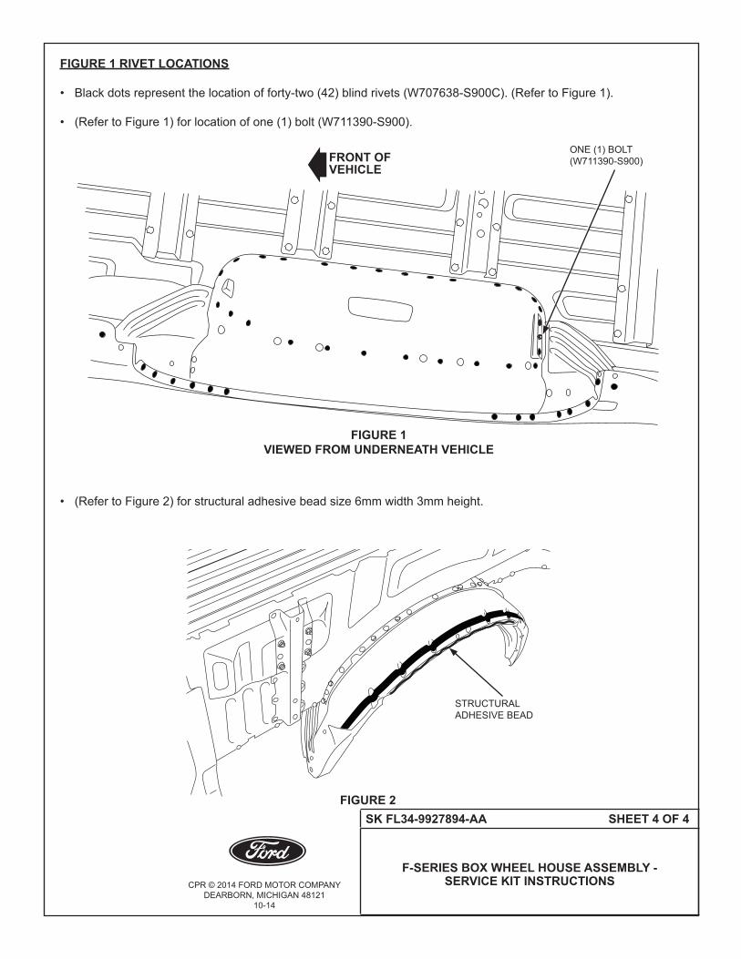
FIGURE 1 RIVET LOCATIONS
• Blackdotsrepresentthelocationofforty-two(42)blindrivets(W707638-S900C).(RefertoFigure1).
• (RefertoFigure1)forlocationofone(1)bolt(W711390-S900).
• (RefertoFigure2)forstructuraladhesivebeadsize6mmwidth3mmheight.
FIGURE 2
FIGURE 1VIEWED FROM UNDERNEATH VEHICLE
FRONT OFVEHICLE
ONE (1) BOLT (W711390-S900)
STRUCTURALADHESIVE BEAD

CPR © 2014 FORD MOTOR COMPANYDEARBORN, MICHIGAN 48121
10-14
SKFL34-1640252-AA SHEET 1 OF 3
F-SERIES BODY INSTALLATION FOR CREW CAB C-PILLAR INNER - SERVICE KIT INSTRUCTIONS
F-SERIES BODY INSTALLATION FOR CREW CAB C-PILLAR INNER - SERVICE KIT INSTRUCTIONS
KITPart Number Description Quantity
FL34-1640252-AH C-Pillar Inner Crew Cab (RH) 1SKFL34-1640252-AA Instruction Sheet 1
KIT Part Number Description Quantity
FL34-1640253-AH C-Pillar Inner Crew Cab (LH) 1SKFL34-1640252-AA Instruction Sheet 1
KIT Part Number Description Quantity
FL34-16250A08-AC C-Pillar Reinforcement Crew Cab (RH) 1SKFL34-1640252-AA Instruction Sheet 1
KIT Part Number Description Quantity
FL34-16250A09-AC C-Pillar Reinforcement Crew Cab (RH) 1SKFL34-1640252-AA Instruction Sheet 1
KIT Part Number Description Quantity
FL34-1526590-AC Door Skin Striker Both Sides 1SKFL34-1640252-AA Instruction Sheet 1
NOT INCLUDED IN KIT (PROCURE LOCALLY)Part Number Description Quantity
W702512-S900C Blind Rivet 8Motorcraft TA-1, 3M 8115 or Fusor 108B
Metal Panel Bonding Adhesive 1

CPR © 2014 FORD MOTOR COMPANYDEARBORN, MICHIGAN 48121
10-14
SKFL34-1640252-AA SHEET 2 OF 3
F-SERIES BODY INSTALLATION FOR CREW CAB C-PILLAR INNER - SERVICE KIT INSTRUCTIONS
SERVICE GUIDELINES:
• Aluminumrepairsshouldbeperformedinanareaprotectedfromsteelworkingareas,andtoolsusedin aluminumrepairshouldbequarantinedfromsteelrepairtools. • ReplacementSelf-PiercingRivets(SPRs)arethepreferredreplacementduringrepairfororiginalSPR locations,wherefeasible.BlindrivetsarethenextpreferredreplacementfororiginalSPRs.Insomecases,solid rivetsmayalsobeusedasareplacementforSPRs.Thefigureswillexplicitlycalloutwhichrivetsarepossible. • ReplacementSPRsaretobeinstalledadjacenttooriginalSPRlocation.
NOTE: Do not install replacement SPR in original SPR hole.
• BlindrivetsmaybeinstalledinoriginalSPRholes,aftertheyarereamedoutto6.5mm.Besuretogrindall surfacesoftheflangesmoothpriortoblindrivetinstallationinoriginalSPRlocations.
• FlowDrillScrews(FDS)aretobereplacedbyblindrivetsonly.TheoriginallocationoftheFDSisused,but reamedoutto6.5mm.
• Rivetsmayberemovedbydrilling,grinding,orSPRgunsetupasarivetremovaltool.
• Usingheat(notexceeding425°F)toloosenarivetbondedpanelshouldonlybedonewhenallpanelsinthe jointwillbereplacedorseparatedandnewadhesiveapplied.
• Flangepreparationforadhesiveistogrindtocleanmetalwith80-120grit,clean,andthenapplytheadhesive, spreadingitoutwithanacidbrush,coveringanyexposedaluminum.
• Clecosareanexcellentwaytoholdthepanelsintopositionwhenfittinganddrillingrivetholes.

CPR © 2014 FORD MOTOR COMPANYDEARBORN, MICHIGAN 48121
10-14
SKFL34-1640252-AA SHEET 3 OF 3
F-SERIES BODY INSTALLATION FOR CREW CAB C-PILLAR INNER - SERVICE KIT INSTRUCTIONS
FIGURE 1
• (RefertoFigure1)forlocationforadhesivematerial. •SeeC-Pillarouteranddooropeningpanelforassociatedrivets. NOTE: The location of SPR and adhesive shown below are based on the original production drawings and should only be used as a guideline.
BLACK WAVY LINES REPRESENT THE LOCATION OF THE ADHESIVE MATERIAL EIGHT (8)
W702512-S900C BLIND RIVETS
CPR © 2014 FORD MOTOR COMPANYDEARBORN, MICHIGAN 48121
10-14
SKFL34-1510598-AA SHEET 1 OF 4
F-SERIES ALL CABS CENTER FLOOR CROSSMEMBER INSTALLATION -
SERVICE KIT INSTRUCTIONS
F-SERIES ALL CABS CENTER FLOOR CROSSMEMBER INSTALLATION - SERVICE KIT INSTRUCTIONS
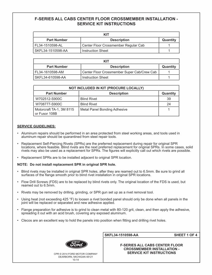
KIT Part Number Description Quantity
FL34-1510598-AL Center Floor Crossmember Regular Cab 1SKFL34-1510598-AA Instruction Sheet 1
KIT Part Number Description Quantity
FL34-1610598-AM Center Floor Crossmember Super Cab/Crew Cab 1SKFL34-610598-AA Instruction Sheet 1
NOT INCLUDED IN KIT (PROCURE LOCALLY)Part Number Description Quantity
W702512-S900C Blind Rivet 39W708777-S900C Blind Rivet 24Motorcraft TA-1, 3M 8115 or Fusor 108B
Metal Panel Bonding Adhesive 1
SERVICE GUIDELINES:
• Aluminumrepairsshouldbeperformedinanareaprotectedfromsteelworkingareas,andtoolsusedin aluminum repair should be quarantined from steel repair tools. • ReplacementSelf-PiercingRivets(SPRs)arethepreferredreplacementduringrepairfororiginalSPR locations, where feasible. Blind rivets are the next preferred replacement for original SPRs. In some cases, solid rivetsmayalsobeusedasareplacementforSPRs.Thefigureswillexplicitlycalloutwhichrivetsarepossible. • ReplacementSPRsaretobeinstalledadjacenttooriginalSPRlocation.
NOTE: Do not install replacement SPR in original SPR hole.
• BlindrivetsmaybeinstalledinoriginalSPRholes,aftertheyarereamedoutto6.5mm.Besuretogrindall surfacesoftheflangesmoothpriortoblindrivetinstallationinoriginalSPRlocations.
• FlowDrillScrews(FDS)aretobereplacedbyblindrivetsonly.TheoriginallocationoftheFDSisused,but reamed out to 6.5mm.
• Rivetsmayberemovedbydrilling,grinding,orSPRgunsetupasarivetremovaltool.
• Usingheat(notexceeding425°F)toloosenarivetbondedpanelshouldonlybedonewhenallpanelsinthe jointwillbereplacedorseparatedandnewadhesiveapplied.
• Flangepreparationforadhesiveistogrindtocleanmetalwith80-120grit,clean,andthenapplytheadhesive, spreading it out with an acid brush, covering any exposed aluminum.
• Clecosareanexcellentwaytoholdthepanelsintopositionwhenfittinganddrillingrivetholes.
CPR © 2014 FORD MOTOR COMPANYDEARBORN, MICHIGAN 48121
10-14
SKFL34-1510598-AA SHEET 2 OF 4
F-SERIES ALL CABS CENTER FLOOR CROSSMEMBER INSTALLATION -
SERVICE KIT INSTRUCTIONS
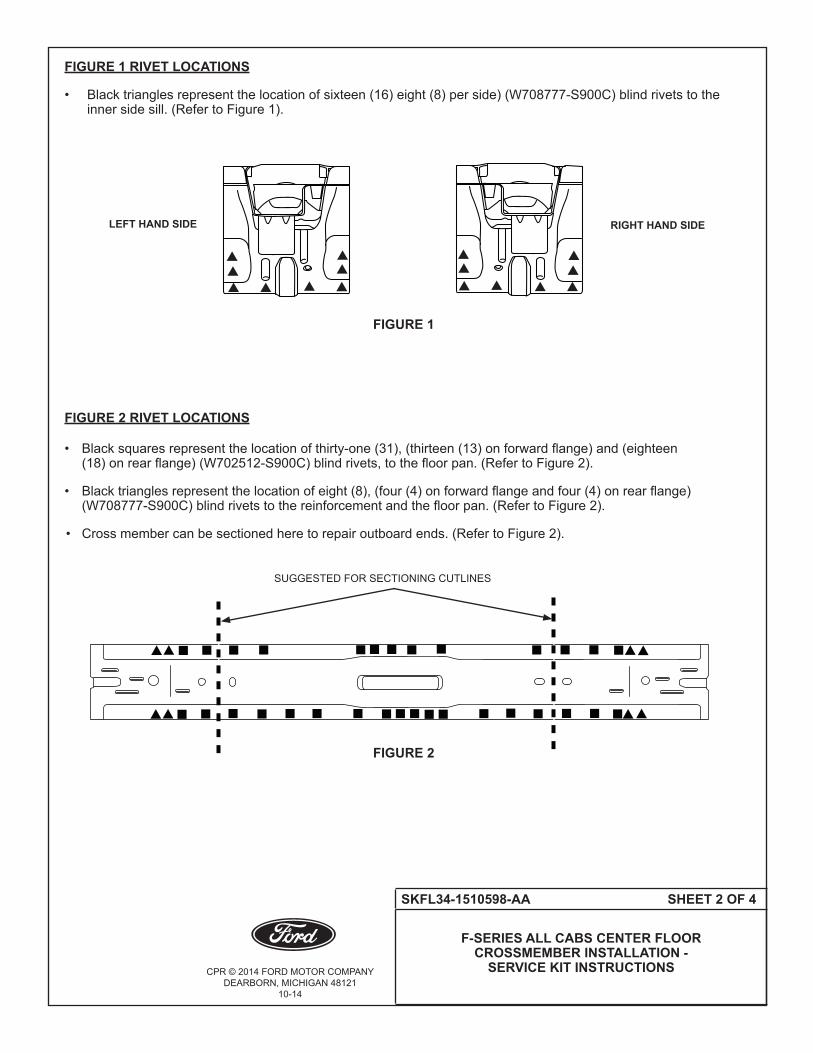
FIGURE 1 RIVET LOCATIONS
• Blacktrianglesrepresentthelocationofsixteen(16)eight(8)perside)(W708777-S900C)blindrivetstothe innersidesill.(RefertoFigure1).
FIGURE 2 RIVET LOCATIONS • Blacksquaresrepresentthelocationofthirty-one(31),(thirteen(13)onforwardflange)and(eighteen (18)onrearflange)(W702512-S900C)blindrivets,tothefloorpan.(RefertoFigure2).
• Blacktrianglesrepresentthelocationofeight(8),(four(4)onforwardflangeandfour(4)onrearflange) (W708777-S900C)blindrivetstothereinforcementandthefloorpan.(RefertoFigure2).
• Crossmembercanbesectionedheretorepairoutboardends.(RefertoFigure2).
FIGURE 1
RIGHT HAND SIDELEFT HAND SIDE
SUGGESTEDFORSECTIONINGCUTLINES
FIGURE 2
CPR © 2014 FORD MOTOR COMPANYDEARBORN, MICHIGAN 48121
10-14
SKFL34-1510598-AA SHEET 3 OF 4
F-SERIES ALL CABS CENTER FLOOR CROSSMEMBER INSTALLATION -
SERVICE KIT INSTRUCTIONS
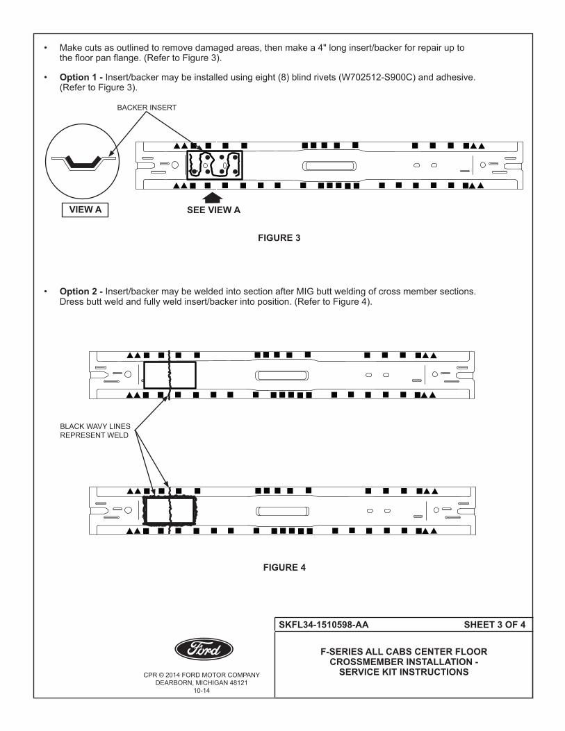
• Makecutsasoutlinedtoremovedamagedareas,thenmakea4"longinsert/backerforrepairupto thefloorpanflange.(RefertoFigure3).
• Option 1 - Insert/backermaybeinstalledusingeight(8)blindrivets(W702512-S900C)andadhesive. (RefertoFigure3).
• Option 2 - Insert/backermaybeweldedintosectionafterMIGbuttweldingofcrossmembersections. Dressbuttweldandfullyweldinsert/backerintoposition.(RefertoFigure4).
FIGURE 3
SEE VIEW AVIEW A
BACKER INSERT
FIGURE 4
BLACK WAVY LINES REPRESENT WELD

CPR © 2014 FORD MOTOR COMPANYDEARBORN, MICHIGAN 48121
10-14
SKFL34-1510598-AA SHEET 4 OF 4
F-SERIES ALL CABS CENTER FLOOR CROSSMEMBER INSTALLATION -
SERVICE KIT INSTRUCTIONS
• (RefertoFigures5and6)forlocationforadhesivematerial.
NOTE: The location of SPR and adhesive shown below are based on the original production drawings and should only be used as a guideline.
FIGURE 6
FIGURE 5
BLACK WAVY LINES REPRESENT THE LOCATION OF THE ADHESIVE MATERIAL
RIGHT HAND SIDELEFT HAND SIDE
BLACK WAVY LINES REPRESENT THE LOCATION OF THE ADHESIVE MATERIAL

CPR © 2014 FORD MOTOR COMPANYDEARBORN, MICHIGAN 48121
10-14
SKFL34-1502220-AA SHEET 1 OF 3
F-SERIES COWL SIDE PANEL INSTALLATIONSERVICE KIT INSTRUCTIONS
F-SERIES COWL SIDE PANEL INSTALLATION - SERVICE KIT INSTRUCTIONSKIT
Part Number Description QuantityFL34-1502220-AR Panel Assembly Cowl Side (RH) 1SKFL34-1502220-AA Instruction Sheet 1
KITPart Number Description Quantity
FL34-1502221-AL Panel Assembly Cowl Side (LH) 1SKFL34-1502220-AA Instruction Sheet 1
NOT INCLUDED IN KIT (PROCURE LOCALLY)Part Number Description Quantity
W702512-S900C Blind Rivet 46W716421-S450 Pierce Nut M8 13W716422-S450 Pierce Nut M6 3W710246-S900 Self-Piercing Rivet (SPR) Code BN 6Motorcraft TA-1, 3M 8115 or Fusor 108B
Metal Panel Bonding Adhesive 1
SERVICE GUIDELINES:
• Aluminumrepairsshouldbeperformedinanareaprotectedfromsteelworkingareas,andtoolsusedin aluminumrepairshouldbequarantinedfromsteelrepairtools. • ReplacementSelf-PiercingRivets(SPRs)arethepreferredreplacementduringrepairfororiginalSPR locations,wherefeasible.BlindrivetsarethenextpreferredreplacementfororiginalSPRs.Insomecases,solid rivetsmayalsobeusedasareplacementforSPRs.Thefigureswillexplicitlycalloutwhichrivetsarepossible. • ReplacementSPRsaretobeinstalledadjacenttooriginalSPRlocation.
NOTE: Do not install replacement SPR in original SPR hole.
• BlindrivetsmaybeinstalledinoriginalSPRholes,aftertheyarereamedoutto6.5mm.Besuretogrindall surfacesoftheflangesmoothpriortoblindrivetinstallationinoriginalSPRlocations.
• FlowDrillScrews(FDS)aretobereplacedbyblindrivetsonly.TheoriginallocationoftheFDSisused,but reamedoutto6.5mm.
• Rivetsmayberemovedbydrilling,grinding,orSPRgunsetupasarivetremovaltool.
• Usingheat(notexceeding425°F)toloosenarivetbondedpanelshouldonlybedonewhenallpanelsinthe jointwillbereplacedorseparatedandnewadhesiveapplied.
• Flangepreparationforadhesiveistogrindtocleanmetalwith80-120grit,clean,andthenapplytheadhesive, spreadingitoutwithanacidbrush,coveringanyexposedaluminum.
• Clecosareanexcellentwaytoholdthepanelsintopositionwhenfittinganddrillingrivetholes.

CPR © 2014 FORD MOTOR COMPANYDEARBORN, MICHIGAN 48121
10-14
SKFL34-1502220-AA SHEET 2 OF 3
F-SERIES COWL SIDE PANEL INSTALLATIONSERVICE KIT INSTRUCTIONS
FIGURE 1 RIVET LOCATIONS
• (RefertoFigure1)foroptionalSPRrivetsandinstallationMandrels.
NOTE: The location of SPR and adhesive shown below are based on the original production drawings and should only be used as a guideline. (Refer to Figure 2).
FIGURE 1
THREE (3)W710246-S900BN DG10-200/HORW702512-S900CBLIND RIVETS
ELEVEN (11)W702512-S900CBLIND RIVETS ONLY
ELEVEN (11)W702512-S900CBLIND RIVETS ONLY
THREE (3)W702512-S900CBLIND RIVETS ONLY
THREE (3)W710246-S900BN DG10-200/HORW702512-S900CBLIND RIVETS
THREE (3)W702512-S900CBLIND RIVETS ONLY
SIX (6)W702512-S900CBLIND RIVETS ONLY
SIX (6)W702512-S900CBLIND RIVETS ONLY
2
SQUARED NUMBERS ARE PRO SPOT MANDRELS1 SA-0400/SA-04012 SA-0400/SA-0402
2

CPR © 2014 FORD MOTOR COMPANYDEARBORN, MICHIGAN 48121
10-14
SKFL34-1502220-AA SHEET 3 OF 3
F-SERIES COWL SIDE PANEL INSTALLATIONSERVICE KIT INSTRUCTIONS
FIGURE 2
BLACK WAVY LINES REPRESENT THE LOCATION OF THE ADHESIVE MATERIAL
FIGURE 3
FIVE (5)W716421-S450PIERCENUTM8
ONE (1)W716422-S450PIERCENUTM6
TWO (2)W716422-S450PIERCENUTM6
FIVE (5)W716421-S450PIERCENUTM8
THREE (3)W716421-S450PIERCENUTM8
• (RefertoFigure3)forrequiredpiercenutlocations.

CPR © 2014 FORD MOTOR COMPANYDEARBORN, MICHIGAN 48121
10-14
SKFL34-1502018-AA SHEET 1 OF 4
SERVICE KIT INSTRUCTIONS ALL CABS
F-SERIES COWL TOP INNER INSTALLATION - SERVICE KIT INSTRUCTIONS ALL CABS
KIT Part Number Description Quantity
FL34-1502018-AJ Cowl Top Inner All Cabs 1SKFL34-1502018-AA Instruction Sheet 1
KIT Part Number Description Quantity
FL34-15020K64-AB Wiper Blade Bracket (LH) 1SKFL34-1502018-AA Instruction Sheet 1
KIT Part Number Description Quantity
FL34-15020B72-AA Wiper Blade Bracket (RH) 1SKFL34-1502018-AA Instruction Sheet 1
KIT Part Number Description Quantity
FL34-15044H29-AC Brake Pedal Reinforcement 1SKFL34-1502018-AA Instruction Sheet 1
KIT Part Number Description Quantity
FL34-15045K03-AD Instrument Panel Reinforcement 1SKFL34-1502018-AA Instruction Sheet 1
NOT INCLUDED IN KIT (PROCURE LOCALLY)Part Number Description Quantity
W702512-S900C Blind Rivet 86W708777-S900C Blind Rivet 22W790376-S900 Solid Rivet 32W708713-S900 Self-Piercing Rivet (SPR) Code AS 32Motorcraft TA-1, 3M 8115 or Fusor 108B
Metal Panel Bonding Adhesive 1
CPR © 2014 FORD MOTOR COMPANYDEARBORN, MICHIGAN 48121
10-14
SKFL34-1502018-AA SHEET 2 OF 4
F-SERIES COWL TOP INNER INSTALLATION - SERVICE KIT INSTRUCTIONS ALL CABS
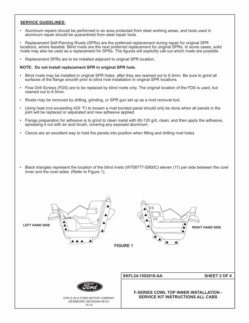
SERVICE GUIDELINES:
• Aluminumrepairsshouldbeperformedinanareaprotectedfromsteelworkingareas,andtoolsusedin aluminum repair should be quarantined from steel repair tools. • ReplacementSelf-PiercingRivets(SPRs)arethepreferredreplacementduringrepairfororiginalSPR locations, where feasible. Blind rivets are the next preferred replacement for original SPRs. In some cases, solid rivetsmayalsobeusedasareplacementforSPRs.Thefigureswillexplicitlycalloutwhichrivetsarepossible. • ReplacementSPRsaretobeinstalledadjacenttooriginalSPRlocation.
NOTE: Do not install replacement SPR in original SPR hole.
• BlindrivetsmaybeinstalledinoriginalSPRholes,aftertheyarereamedoutto6.5mm.Besuretogrindall surfacesoftheflangesmoothpriortoblindrivetinstallationinoriginalSPRlocations.
• FlowDrillScrews(FDS)aretobereplacedbyblindrivetsonly.TheoriginallocationoftheFDSisused,but reamed out to 6.5mm.
• Rivetsmayberemovedbydrilling,grinding,orSPRgunsetupasarivetremovaltool.
• Usingheat(notexceeding425°F)toloosenarivetbondedpanelshouldonlybedonewhenallpanelsinthe jointwillbereplacedorseparatedandnewadhesiveapplied.
• Flangepreparationforadhesiveistogrindtocleanmetalwith80-120grit,clean,andthenapplytheadhesive, spreading it out with an acid brush, covering any exposed aluminum.
• Clecosareanexcellentwaytoholdthepanelsintopositionwhenfittinganddrillingrivetholes.
• Blacktrianglesrepresentthelocationoftheblindrivets(W708777-S900C)eleven(11)persidebetweenthecowl inner and the cowl sides. (Refer to Figure 1).
RIGHT HAND SIDELEFT HAND SIDE
FIGURE 1

CPR © 2014 FORD MOTOR COMPANYDEARBORN, MICHIGAN 48121
10-14
SKFL34-1502018-AA SHEET 3 OF 4
SERVICE KIT INSTRUCTIONS ALL CABS
NOTE: Service SPR rivets may be used on the top also on forward flange and fifteen (15) on rear flange). (Refer to Figure 2).
FIGURE 2
SEVENTEEN (17)W708713-S900AS INSTALLED USINGMANDRELDZ09-025/HOR W702512-S900C BLIND RIVETS
THIRTY-TWO (32) W702512-S900C BLIND RIVETS FROM COWL LOWER TO STEEL DASH PANEL
FIFTEEN (15)W708713-S900AS SPR RIVETS OR W702512-S900C BLIND RIVETSFROM COWL LOWER TO COWL TOPOUTER
FRONT OFVEHICLE1
SIX (6) W702512-S900C BLIND RIVETS ONLY
FOUR(4)W702512-S900C BLIND RIVETS ONLY
1
FIGURE 3
TWELVE (12) W702512-S900C BLIND RIVETS ONLY
SQUARED NUMBERS ARE PRO SPOT MANDRELS1 SA-0400/SA-04012 SA-0400/SA-0402
CIRCLED NUMBERS ARE SOLID RIVETS1 W790376-S9002 W790377-S900
1
1
CPR © 2014 FORD MOTOR COMPANYDEARBORN, MICHIGAN 48121
10-14
SKFL34-1502018-AA SHEET 4 OF 4
F-SERIES COWL TOP INNER INSTALLATION - SERVICE KIT INSTRUCTIONS ALL CABS
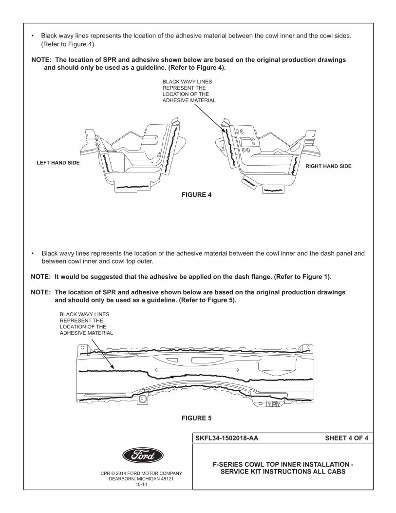
• Blackwavylinesrepresentsthelocationoftheadhesivematerialbetweenthecowlinnerandthecowlsides. (Refer to Figure 4).
NOTE: The location of SPR and adhesive shown below are based on the original production drawings and should only be used as a guideline. (Refer to Figure 4).
• Blackwavylinesrepresentsthelocationoftheadhesivematerialbetweenthecowlinnerandthedashpaneland between cowl inner and cowl top outer.
NOTE: It would be suggested that the adhesive be applied on the dash flange. (Refer to Figure 1).
NOTE: The location of SPR and adhesive shown below are based on the original production drawings and should only be used as a guideline. (Refer to Figure 5).
BLACK WAVY LINES REPRESENT THE LOCATION OF THE ADHESIVE MATERIAL
FIGURE 5
BLACK WAVY LINES REPRESENT THE LOCATION OF THE ADHESIVE MATERIAL
RIGHT HAND SIDELEFT HAND SIDE
FIGURE 4
CPR © 2014 FORD MOTOR COMPANYDEARBORN, MICHIGAN 48121
11-14
SKFL34-16211A10-AB SHEET 1 OF 6
F-SERIES BODY INSTALLATION FOR CREW CAB DOOR OPENING PANEL -
SERVICE KIT INSTRUCTIONS
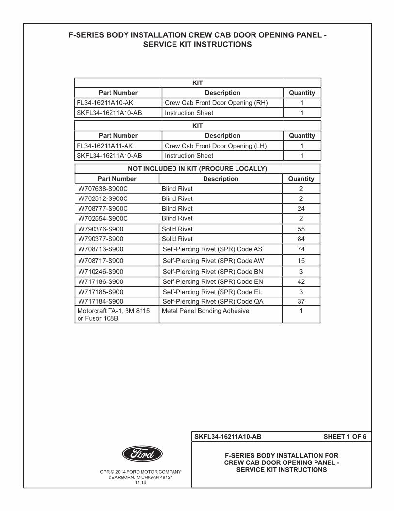
F-SERIES BODY INSTALLATION CREW CAB DOOR OPENING PANEL - SERVICE KIT INSTRUCTIONS
KIT Part Number Description Quantity
FL34-16211A10-AK Crew Cab Front Door Opening (RH) 1SKFL34-16211A10-AB Instruction Sheet 1
KIT Part Number Description Quantity
FL34-16211A11-AK Crew Cab Front Door Opening (LH) 1SKFL34-16211A10-AB Instruction Sheet 1
NOT INCLUDED IN KIT (PROCURE LOCALLY)Part Number Description Quantity
W707638-S900C Blind Rivet 2W702512-S900C Blind Rivet 2W708777-S900C Blind Rivet 24W702554-S900C Blind Rivet 2W790376-S900 Solid Rivet 55W790377-S900 Solid Rivet 84W708713-S900 Self-Piercing Rivet (SPR) Code AS 74
W708717-S900 Self-Piercing Rivet (SPR) Code AW 15
W710246-S900 Self-Piercing Rivet (SPR) Code BN 3W717186-S900 Self-Piercing Rivet (SPR) Code EN 42W717185-S900 Self-Piercing Rivet (SPR) Code EL 3W717184-S900 Self-Piercing Rivet (SPR) Code QA 37Motorcraft TA-1, 3M 8115 or Fusor 108B
Metal Panel Bonding Adhesive 1

CPR © 2014 FORD MOTOR COMPANYDEARBORN, MICHIGAN 48121
11-14
SKFL34-16211A10-AB SHEET 2 OF 6
F-SERIES BODY INSTALLATION FOR CREW CAB DOOR OPENING PANEL -
SERVICE KIT INSTRUCTIONS
SERVICE GUIDELINES:
• Aluminumrepairsshouldbeperformedinanareaprotectedfromsteelworkingareas,andtoolsusedin aluminumrepairshouldbequarantinedfromsteelrepairtools. • ReplacementSelf-PiercingRivets(SPRs)arethepreferredreplacementduringrepairfororiginalSPR locations,wherefeasible.BlindrivetsarethenextpreferredreplacementfororiginalSPRs.Insomecases,solid rivetsmayalsobeusedasareplacementforSPRs.Thefigureswillexplicitlycalloutwhichrivetsarepossible. • ReplacementSPRsaretobeinstalledadjacenttooriginalSPRlocation.
NOTE: Do not install replacement SPR in original SPR hole.
• BlindrivetsmaybeinstalledinoriginalSPRholes,aftertheyarereamedoutto6.5mm.Besuretogrindall surfacesoftheflangesmoothpriortoblindrivetinstallationinoriginalSPRlocations.
• FlowDrillScrews(FDS)aretobereplacedbyblindrivetsonly.TheoriginallocationoftheFDSisused,but reamedoutto6.5mm.
• Rivetsmayberemovedbydrilling,grinding,orSPRgunsetupasarivetremovaltool.
• Usingheat(notexceeding425°F)toloosenarivetbondedpanelshouldonlybedonewhenallpanelsinthe jointwillbereplacedorseparatedandnewadhesiveapplied.
• Flangepreparationforadhesiveistogrindtocleanmetalwith80-120grit,clean,andthenapplytheadhesive, spreadingitoutwithanacidbrush,coveringanyexposedaluminum.
• Clecosareanexcellentwaytoholdthepanelsintopositionwhenfittinganddrillingrivetholes.
CPR © 2014 FORD MOTOR COMPANYDEARBORN, MICHIGAN 48121
11-14
SKFL34-16211A10-AB SHEET 3 OF 6
F-SERIES BODY INSTALLATION FOR CREW CAB DOOR OPENING PANEL -
SERVICE KIT INSTRUCTIONS
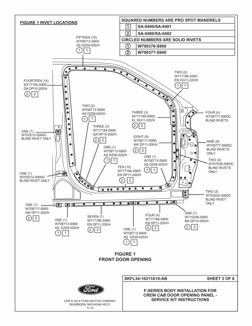
FIGURE 1 RIVET LOCATIONS
FIGURE 1FRONT DOOR OPENING
FIFTEEN (15)W708713-S900 AS DZ09-025/H
TWO (2)W717186-S900EN DG11-220/H
THREE (3)W717185-S900EL DG11-220/H
FOUR(4)W708777-S900CBLIND RIVETS
TWO (2)W707638-S900CBLIND RIVETSONLY
NINE (9)W708777-S900CBLIND RIVETSONLY
EIGHT (8)W708717-S900 AW DP11-200/H
ONE (1)W708713-S900 AS DZ09-025/H
TWO (2)W702554-S900CBLIND RIVETONLY
ONE (1)W710246-S900BN DP10-200/H
FOUR(4)W717186-S900EN DP11-200/H
ONE (1)W708713-S900 AS DZ09-025/H
SEVEN (7)W717186-S900EN DP11-200/H
ONE (1)W708713-S900 AS DZ09-025/H
ONE (1)W708717-S900 AW DP11-200/H
ONE (1)W702512-S900C BLIND RIVET ONLY
ONE (1)W702512-S900C BLIND RIVET ONLY
TEN (10)W717186-S900EN DP11-200/H
THREE (3)W717184-S900QA DP10-200/H
TWO (2)W708713-S900 AS DZ09-025/H
FOURTEEN(14)W717184-S900QA DP10-200/H
1
1
1
222
2
1
2
1
2
ONE (1)W708713-S900 AS DZ09-025/H
1
2
1
2
2
1
1
1
22
1
12
2
1
2
1
2
2
2
2
SQUARED NUMBERS ARE PRO SPOT MANDRELS1 SA-0400/SA-04012 SA-0400/SA-0402
CIRCLED NUMBERS ARE SOLID RIVETS1 W790376-S9002 W790377-S900

CPR © 2014 FORD MOTOR COMPANYDEARBORN, MICHIGAN 48121
11-14
SKFL34-16211A10-AB SHEET 4 OF 6
F-SERIES BODY INSTALLATION FOR CREW CAB DOOR OPENING PANEL -
SERVICE KIT INSTRUCTIONS
FIGURE 2 RIVET LOCATIONS
FIGURE 2REAR DOOR OPENING
NINE (9)W708713-S900 AS DZ09-025/H
TWENTY (20)W717184-S900QA DP10-200/H
THREE (3)W708717-S900 AW DP11-200/H
ONE (1)W708717-S900 AW DP11-200/H
ONE (1)W708713-S900 AS DZ09-025/H
TWO (2)W708717-S900 AW DG10-220/H
NINE (9)W708713-S900 AS DZ09-025/H
SEVEN (7)W717186-S900EN DP11-200/H
FOUR(4)W717186-S900EN DP11-200/H
FIVE (5)W717186-S900EN DG11-220/H
THREE (3)W717186-S900EN DG11-220/H ONE (1)
W708713-S900 AS DZ09-025/H
1
2
2
1
1
2 2
1 1
1
2
2
ONE (1)W702512-S900C BLIND RIVET ONLY
2
1
2
2
2
1
1
22
1 1 1
SQUARED NUMBERS ARE PRO SPOT MANDRELS1 SA-0400/SA-04012 SA-0400/SA-0402
CIRCLED NUMBERS ARE SOLID RIVETS1 W790376-S9002 W790377-S900
CPR © 2014 FORD MOTOR COMPANYDEARBORN, MICHIGAN 48121
11-14
SKFL34-16211A10-AB SHEET 5 OF 6
F-SERIES BODY INSTALLATION FOR CREW CAB DOOR OPENING PANEL -
SERVICE KIT INSTRUCTIONS
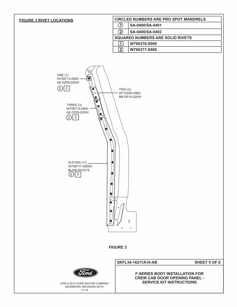
FIGURE 3 RIVET LOCATIONS
FIGURE 3
ELEVEN (11)W708777-S900CBLIND RIVETS
ONE (1)W708713-S900 AS DZ09-025/H
TWO (2)W710246-S900BN DP10-200/H
THREE (3)W708713-S900 AS DZ09-025/H
2 2
2 2
2 2
CIRCLED NUMBERS ARE PRO SPOT MANDRELS1 SA-0400/SA-04012 SA-0400/SA-0402
SQUARED NUMBERS ARE SOLID RIVETS1 W790376-S9002 W790377-S900

CPR © 2014 FORD MOTOR COMPANYDEARBORN, MICHIGAN 48121
11-14
SKFL34-16211A10-AB SHEET 6 OF 6
F-SERIES BODY INSTALLATION FOR CREW CAB DOOR OPENING PANEL -
SERVICE KIT INSTRUCTIONS
FIGURE 4 RIVET LOCATIONS
• (RefertoFigure5)forlocationforadhesivematerial.
NOTE: The location of SPR and adhesive shown below are based on the original production drawings and should only be used as a guideline. (Refer to Figure 5).
BLACK WAVY LINES REPRESENT THE LOCATION OF THE ADHESIVE MATERIAL
FIGURE 5
FIGURE 4
TWO (2)W708713-S900 AS DZ09-025/H
TWENTY-SEVEN (27)W708713-S900 AS DZ09-025/H
2 2
2 2
CPR © 2014 FORD MOTOR COMPANYDEARBORN, MICHIGAN 48121
10-14
SKFL34-1511170-AA SHEET 1 OF 2
F-SERIES FLOOR PAN TUNNEL INSTALLATION - SERVICE KIT INSTRUCTIONS
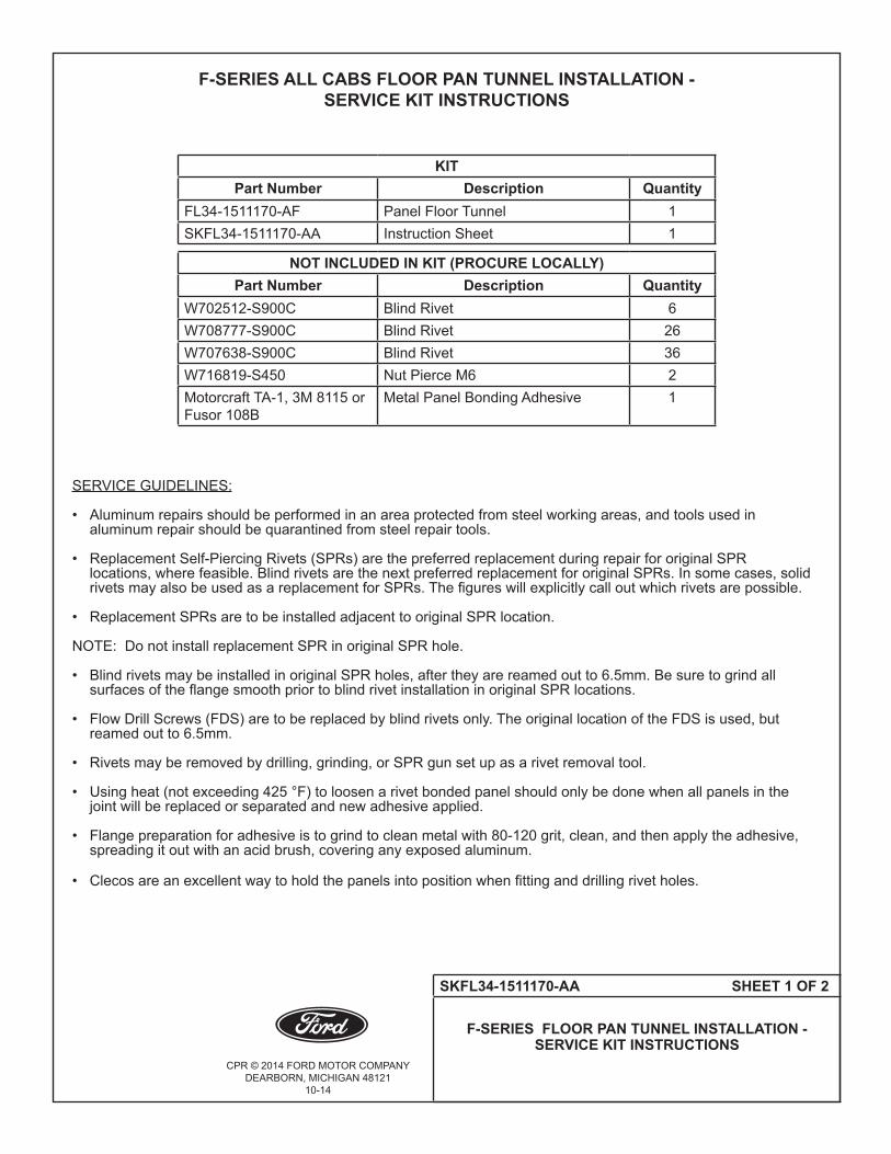
F-SERIES ALL CABS FLOOR PAN TUNNEL INSTALLATION - SERVICE KIT INSTRUCTIONS
KIT Part Number Description Quantity
FL34-1511170-AF Panel Floor Tunnel 1SKFL34-1511170-AA Instruction Sheet 1
NOT INCLUDED IN KIT (PROCURE LOCALLY)Part Number Description Quantity
W702512-S900C Blind Rivet 6W708777-S900C Blind Rivet 26W707638-S900C Blind Rivet 36W716819-S450 Nut Pierce M6 2Motorcraft TA-1, 3M 8115 or Fusor 108B
Metal Panel Bonding Adhesive 1
SERVICE GUIDELINES:
• Aluminumrepairsshouldbeperformedinanareaprotectedfromsteelworkingareas,andtoolsusedin aluminumrepairshouldbequarantinedfromsteelrepairtools. • ReplacementSelf-PiercingRivets(SPRs)arethepreferredreplacementduringrepairfororiginalSPR locations,wherefeasible.BlindrivetsarethenextpreferredreplacementfororiginalSPRs.Insomecases,solid rivetsmayalsobeusedasareplacementforSPRs.Thefigureswillexplicitlycalloutwhichrivetsarepossible. • ReplacementSPRsaretobeinstalledadjacenttooriginalSPRlocation.
NOTE:DonotinstallreplacementSPRinoriginalSPRhole.
• BlindrivetsmaybeinstalledinoriginalSPRholes,aftertheyarereamedoutto6.5mm.Besuretogrindall surfacesoftheflangesmoothpriortoblindrivetinstallationinoriginalSPRlocations.
• FlowDrillScrews(FDS)aretobereplacedbyblindrivetsonly.TheoriginallocationoftheFDSisused,but reamedoutto6.5mm.
• Rivetsmayberemovedbydrilling,grinding,orSPRgunsetupasarivetremovaltool.
• Usingheat(notexceeding425°F)toloosenarivetbondedpanelshouldonlybedonewhenallpanelsinthe jointwillbereplacedorseparatedandnewadhesiveapplied.
• Flangepreparationforadhesiveistogrindtocleanmetalwith80-120grit,clean,andthenapplytheadhesive, spreadingitoutwithanacidbrush,coveringanyexposedaluminum.
• Clecosareanexcellentwaytoholdthepanelsintopositionwhenfittinganddrillingrivetholes.

CPR © 2014 FORD MOTOR COMPANYDEARBORN, MICHIGAN 48121
10-14
SKFL34-1511170-AA SHEET 2 OF 2
F-SERIES FLOOR PAN TUNNEL INSTALLATION - SERVICE KIT INSTRUCTIONS
FIGURE 1 RIVET LOCATIONS • Blackdotsrepresentthelocationoftherivets(W707638-S900C).
•Twelve(12)rivetstodashpanel.
• Twelve(12)rivets(six(6)perside)tothefloorpan.
• Eight(8)rivetstocenterfloorreinforcement. • Four(4)rivetstothe#1crossmember.
• Blacktrianglesrepresentthelocationforrivets(W702512-S900C)thirty-six(36).
• Blacksquaresrepresentthelocationforrivets(W708777-S900C)one(1)perside. • (RefertoFigure2)forlocationforadhesivematerial.
NOTE: ThelocationofSPRandadhesiveshownbelowarebasedontheoriginalproductiondrawings andshouldonlybeusedasaguideline.(RefertoFigure2).
FIGURE 1
BLACK WAVY LINE REPRESENTS THE LOCATION OF THE ADHESIVEMATERIALBETWEENTHETUNNEL(1511170)ANDTHEFLOORPAN(1511140ANDTHEDASH(1501610).THE ADHESIVE IS APPLIED TO THE TOP SIDE SURFACE ON THEFLOORPANTUNNEL(1511170).
FIGURE 2
CPR © 2014 FORD MOTOR COMPANYDEARBORN, MICHIGAN 48121
10-14
SKFL34-1611140-AA SHEET 1 OF 5
F-SERIES CREW CAB FLOOR PAN INSTALLATION - SERVICE KIT INSTRUCTIONS
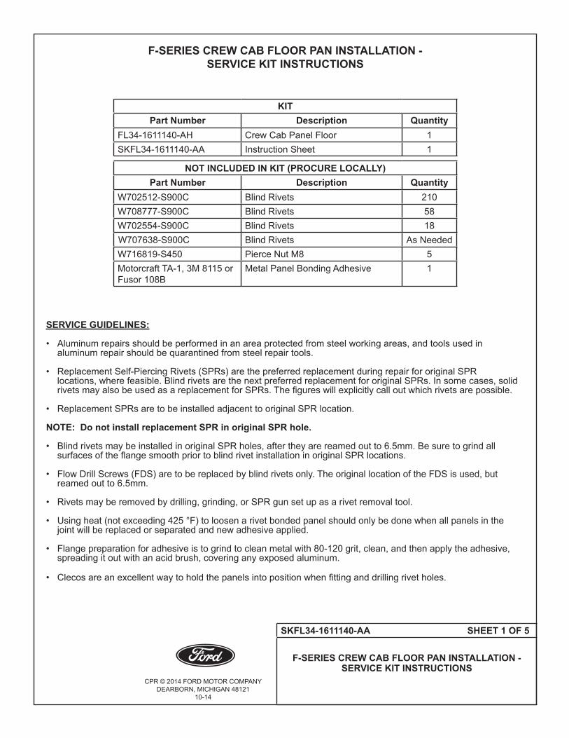
F-SERIES CREW CAB FLOOR PAN INSTALLATION - SERVICE KIT INSTRUCTIONS
KITPart Number Description Quantity
FL34-1611140-AH Crew Cab Panel Floor 1SKFL34-1611140-AA Instruction Sheet 1
NOT INCLUDED IN KIT (PROCURE LOCALLY)Part Number Description Quantity
W702512-S900C Blind Rivets 210W708777-S900C Blind Rivets 58W702554-S900C Blind Rivets 18W707638-S900C Blind Rivets As NeededW716819-S450 Pierce Nut M8 5Motorcraft TA-1, 3M 8115 or Fusor 108B
Metal Panel Bonding Adhesive 1
SERVICE GUIDELINES:
• Aluminumrepairsshouldbeperformedinanareaprotectedfromsteelworkingareas,andtoolsusedin aluminumrepairshouldbequarantinedfromsteelrepairtools. • ReplacementSelf-PiercingRivets(SPRs)arethepreferredreplacementduringrepairfororiginalSPR locations,wherefeasible.BlindrivetsarethenextpreferredreplacementfororiginalSPRs.Insomecases,solid rivetsmayalsobeusedasareplacementforSPRs.Thefigureswillexplicitlycalloutwhichrivetsarepossible. • ReplacementSPRsaretobeinstalledadjacenttooriginalSPRlocation.
NOTE: Do not install replacement SPR in original SPR hole.
• BlindrivetsmaybeinstalledinoriginalSPRholes,aftertheyarereamedoutto6.5mm.Besuretogrindall surfacesoftheflangesmoothpriortoblindrivetinstallationinoriginalSPRlocations.
• FlowDrillScrews(FDS)aretobereplacedbyblindrivetsonly.TheoriginallocationoftheFDSisused,but reamedoutto6.5mm.
• Rivetsmayberemovedbydrilling,grinding,orSPRgunsetupasarivetremovaltool.
• Usingheat(notexceeding425°F)toloosenarivetbondedpanelshouldonlybedonewhenallpanelsinthe jointwillbereplacedorseparatedandnewadhesiveapplied.
• Flangepreparationforadhesiveistogrindtocleanmetalwith80-120grit,clean,andthenapplytheadhesive, spreadingitoutwithanacidbrush,coveringanyexposedaluminum.
• Clecosareanexcellentwaytoholdthepanelsintopositionwhenfittinganddrillingrivetholes.

CPR © 2014 FORD MOTOR COMPANYDEARBORN, MICHIGAN 48121
10-14
SKFL34-1611140-AA SHEET 2 OF 5
F-SERIES CREW CAB FLOOR PAN INSTALLATION - SERVICE KIT INSTRUCTIONS
FIGURE 1 RIVET LOCATIONS
NOTE: The following are common between all cab styles.
• Blacksquaresrepresentthelocationoftherivets(W708777-S900C)
• Eight(8)rivets(four(4)perside)tothereinforcements(15113A46/7)andthe#2crossmember(15/1610598)
• Twelve(12)rivets(six(6)perside)tosledrunner(1510370/1)andtorqueboxextension(1510024/5)
• Two(2)rivets(one(1)perside)to#1crossmember(1510684)andsledrunner(1510370/1)
• Ten(10)rivets(five(5)perside)to#1crossmember(1510684)andtorqueboxextension(1510024/5)
• Four(4)rivets(two(2)perside)totorquebox(1510414/5)andsledrunner(1510370/1)
• Sixteen(16)rivets(eight(8)perside)todash(1501610)andtorquebox(1510414/5)
• Six(6)rivets(three(3)perside)tofloortunnelandtorquebox(1510414/5)
• Blackdotsrepresentthelocationoftherivets(W702554-S900C)
• Eighteen(18)rivets,(nine(9)perside)nexttoovalslotgotothetorquebox(1510414/5)andtorquebox extension(1510024/5).
FIGURE 1
FRONT OFVEHICLE

CPR © 2014 FORD MOTOR COMPANYDEARBORN, MICHIGAN 48121
10-14
SKFL34-1611140-AA SHEET 3 OF 5
F-SERIES CREW CAB FLOOR PAN INSTALLATION - SERVICE KIT INSTRUCTIONS
FIGURE 2 RIVET LOCATIONS • Blackdotsrepresentthelocationoftherivets(W702512-S900C)sixty-six(66)(thirty-three(33)perside) rivetstosidesill.
• Forty(40)rivetstotherearsill(16107A94)
• Thirty(30)rivetstothe#4crossmember • ThirtyFour(34)rivetstothe#2crossmember(1610598)
• Twelve(12)(six(6)perside)tothe#1crossmember(1510692) • Ten(10)rivets(five(5)perside)tothesledrunners(1510370/1)
• Eighteen(18)rivets(nine(9)perside)tothetorqueboxextension(1510024/5)
• (RefertoFigure3)forthefloorpantunnelonpage4 forthelocationandnumberofrivets.
• Blackstarsrepresentthefive(5)piercenuts(W716819-S450)usedtosecurethejack,sub-wooferandamp asneeded.
NOTE: SeethefloorpantunnelinstructionsheetSKFL34-1511170-AA forthelocationandnumberof rivetsrequiredbetweenthem.
FIGURE 2
FRONT OFVEHICLE

CPR © 2014 FORD MOTOR COMPANYDEARBORN, MICHIGAN 48121
10-14
SKFL34-1611140-AA SHEET 4 OF 5
F-SERIES CREW CAB FLOOR PAN INSTALLATION - SERVICE KIT INSTRUCTIONS
• (RefertoFigure5)forlocationforadhesivematerial. NOTE: ThelocationofSPRandadhesiveshownbelowarebasedontheoriginalproductiondrawings andshouldonlybeusedasaguideline.(RefertoFigure5).
FIGURE 5
BLACK WAVY LINES REPRESENT THE LOCATION OF THE ADHESIVE MATERIAL
FRONT OFVEHICLE

CPR © 2014 FORD MOTOR COMPANYDEARBORN, MICHIGAN 48121
10-14
SKFL34-1611140-AA SHEET 5 OF 5
F-SERIES CREW CAB FLOOR PAN INSTALLATION - SERVICE KIT INSTRUCTIONS
SECTIONING OF THE FLOOR PAN NOTE:Partialsectioningofthefloorpanisallowed,basedontechnicianjudgementandextentofdamage. Forarobustandproperrepair,thefollowingcriteriamustbemet:
• Thedamagedareaismeasuredandpulled/restoredbacktooriginaldimensionalcondition. • Therepairareamustbeatleast50mmawayfromtheseatmountingtracklocationsonthefloorpan.
• Therepairpanelmustbeinstalledtocrossmembers/sills/rockersusingthespecifiedrivetpatternsand rivettype/sizes.(RefertoFigures1-3).
• Atleasta1"overlappingflangeismaintainedbetweentherepairandoriginalrepairpanels.
• Therepairpanelflangemustbepreparedandadhesivefullyappliedasperthegeneralinformationguidelines.
• TherepairflangerivetsareBlindRivets(W707638-S900C).Thenumberofblindrivetsuseddependsonthe sizeoftherepairpanel.Therivetsmustbeinstallednofurtherthan3"apartaroundentirerepairpanel.
• Afterinstallationoftherepairpaneliscomplete,followallsealing,refinish,andcorrosionprotectionstepsrequired.

CPR © 2016 FORD MOTOR COMPANYDEARBORN, MICHIGAN 48121
4-16
SKFL34-1620204-AB SHEET 1 OF 3
F-SERIES ALL CABS FRONT DOOR OUTER PANEL INSTALLATION - SERVICE KIT INSTRUCTIONS
F-SERIES ALL CABS FRONT DOOR OUTER PANEL INSTALLATION - SERVICE KIT INSTRUCTIONS
KITPart Number Description Quantity
FL34-1620204-A* Front Door Outer Panel - (RH) 1SKFL34-1620204-AB Instruction Sheet 1
KITPart Number Description Quantity
FL34-1620205-A* Front Door Outer Panel - (LH) 1SKFL34-1620204-AB Instruction Sheet 1
NOT INCLUDED IN KIT (PROCURE LOCALLY)Part Number Description Quantity
W790376-S900 Solid Rivet 10W708717-S900 SPR Rivet Code AW 10Rotunda 501-078-1 Hem Opening Tools (RH) 1Rotunda 501-078-2 Hem Opening Tools (LH) 1501-080 Hem Closing Tool 1Motorcraft TA-1, 3M 8115 or Fusor 108B
Metal Panel Bonding Adhesive 1
SERVICE GUIDELINES:
1. Aluminum repairs should be performed in an area protected from steel working areas, and tools used in aluminum repair should be quarantined from steel repair tools.
2. Any rivets on bottom door hem are for original manufacturer purposes only and are not replaced during the service door outer panel replacement procedure. 3. Remove the door trim panel from the affected door and window glass. For additional information, refer to Section 501-11.
4. Remove the outside door handle and mirror assembly. For additional information, refer to Section 501-09.
5. Remove door trim including mouldings and weather strips.
6. Remove the door assembly and secure on a work stand.
7. Remove all SPR rivets outlined at door shut face, then insert TOOL 501-078-1 (RH) or TOOL 501-078-2 (LH) in an air impact gun (620 kPa (90 psi) air pressure is required for consistent tool operation). Using the tool, open thehemflangearoundtheperimeterofthepanel.
NOTE: The use of a heat gun may be required to soften door panel adhesive.
8. Useasharpknifetocuttheadhesivebetweenthedoorouteroriginalpanel,flutterbeam,beltlinereinforcement and intrusion beam.
9. Remove original door outer panel.

CPR © 2016 FORD MOTOR COMPANYDEARBORN, MICHIGAN 48121
4-16
SKFL34-1620204-AB SHEET 2 OF 3
F-SERIES ALL CABS FRONT DOOR OUTER PANEL INSTALLATION - SERVICE KIT INSTRUCTIONS
10. Scuff sand only, DO NOT GRIND, the inner structure bonding surfaces. Do not sand to bare substrate, leave original e-coat as intact as possible.
11.Trialfittheservicereplacementpaneltothedoorshellassembly.
12. Temporarily secure the outer panel to the door assembly and install on the vehicle to verify proper skin alignment.
13. Use reference marks to assist.
14. Scuff the replacement skin bonding areas, then clean with adhesive cleaner. 15.Applymetalbondingadhesivetothefollowingareas:servicereplacementhemflange,flutterbeam-to-outer panel,andouterbeltreinforcement-to-outerpanel.(Refertofigure1).
16. Using a 501-080 Hem Closing Tool or the hammer and dolly method, close the perimeter door hem and smooth any residual adhesive in the joints. 17. Install ten (10) (W708717-S900) SPR rivets code AW, or (W790376-S900) ten (10) solid rivets. (Refer to Figure 2) 18. Prime and Paint the door following Ford approved paint company materials/guidelines. 19. Install the door to the vehicle, align, and reassemble all components. 20. Apply anti-corrosion treatments as outlined in workshop manual section 501-35
NOTE: The location of SPR and adhesive shown below are based on the original production drawings and should only be used as a guideline. (Refer to Figure 1).
FIGURE 1
BLACK WAVY LINES AND DOTS REPRESENT THE LOCATION OF THE ADHESIVE MATERIAL
CPR © 2016 FORD MOTOR COMPANYDEARBORN, MICHIGAN 48121
4-16
SKFL34-1620204-AB SHEET 3 OF 3
F-SERIES ALL CABS FRONT DOOR OUTER PANEL INSTALLATION - SERVICE KIT INSTRUCTIONS
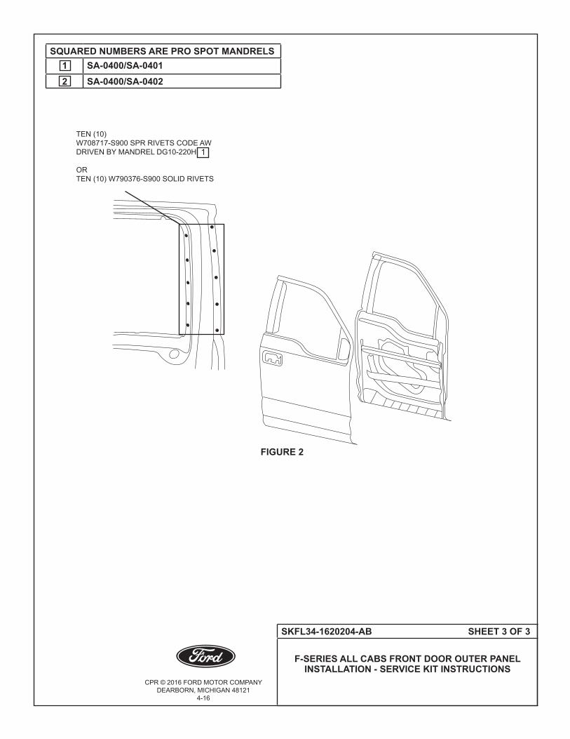
FIGURE 2
SQUARED NUMBERS ARE PRO SPOT MANDRELS1 SA-0400/SA-04012 SA-0400/SA-0402
TEN (10)W708717-S900 SPR RIVETS CODE AW DRIVEN BY MANDREL DG10-220H
OR TEN (10) W790376-S900 SOLID RIVETS
1

CPR © 2014 FORD MOTOR COMPANYDEARBORN, MICHIGAN 48121
10-14
SKFL34-1510692-AA SHEET 1 OF 5
F-SERIES ALL CABS FRONT FLOOR CROSSMEMBER INSTALLATION -
SERVICE KIT INSTRUCTIONS
F-SERIES ALL CABS FRONT FLOOR CROSSMEMBER INSTALLATION - SERVICE KIT INSTRUCTIONS
KITPart Number Description Quantity
FL34-1510692-AD Front Floor Crossmember All Cabs 1SKFL34-1510692-AA Instruction Sheet 1
KIT
Part Number Description QuantityFL34-15111C68-AG Center Floor Reinforcement All Cabs 1SKFL34-1510692-AA Instruction Sheet 1
NOT INCLUDED IN KIT (PROCURE LOCALLY)Part Number Description Quantity
W708777-S900C Blind Rivet 36W702512-S900C Blind Rivet 55Motorcraft TA-1, 3M 8115 or Fusor 108B
Metal Panel Bonding Adhesive 1
KITPart Number Description Quantity
FL34-1510024-AC Torque Box Extension All Cabs - (RH) 1SKFL34-1510692-AA Instruction Sheet 1
KITPart Number Description Quantity
FL34-1510025-AD Torque Box Extension All Cabs - (LH) 1SKFL34-1510692-AA Instruction Sheet 1
NOT INCLUDED IN KIT (PROCURE LOCALLY)Part Number Description Quantity
W708777-S900C Blind Rivet 36W702512-S900C Blind Rivet 55Motorcraft TA-1, 3M 8115 or Fusor 108B
Metal Panel Bonding Adhesive 1
KITPart Number Description Quantity
FL34-1510414-AC Torque Box All Cabs - (RH) 1SKFL34-1510692-AA Instruction Sheet 1
KITPart Number Description Quantity
FL34-1510415-AC Torque Box All Cabs - (LH) 1SKFL34-1510692-AA Instruction Sheet 1

CPR © 2014 FORD MOTOR COMPANYDEARBORN, MICHIGAN 48121
10-14
SKFL34-1510692-AA SHEET 2 OF 5
F-SERIES ALL CABS FRONT FLOOR CROSSMEMBER INSTALLATION -
SERVICE KIT INSTRUCTIONS
NOT INCLUDED IN KIT (PROCURE LOCALLY)Part Number Description Quantity
W708777-S900C Blind Rivet 36W702512-S900C Blind Rivet 55Motorcraft TA-1, 3M 8115 or Fusor 108B
Metal Panel Bonding Adhesive 1
KIT Part Number Description Quantity
FL34-15000L06-AC Body Mount Reinforcement All Cabs - (RH) 1SKFL34-1510692-AA Instruction Sheet 1
KIT Part Number Description Quantity
FL34-15000L07-AD Body Mount Reinforcement All Cabs - (LH) 1SKFL34-1510692-AA Instruction Sheet 1
NOT INCLUDED IN KIT (PROCURE LOCALLY)Part Number Description Quantity
W708777-S900C Blind Rivet 36W702512-S900C Blind Rivet 55Motorcraft TA-1, 3M 8115 or Fusor 108B
Metal Panel Bonding Adhesive 1
KIT Part Number Description Quantity
FL34-1610418-AH Sled Runner All Cabs - (RH) 1SKFL34-1510692-AA Instruction Sheet 1
KIT Part Number Description Quantity
FL34-1610419-AH Sled Runner All Cabs - (LH) 1SKFL34-1510692-AA Instruction Sheet 1
NOT INCLUDED IN KIT (PROCURE LOCALLY)Part Number Description Quantity
W708777-S900C Blind Rivet 36W702512-S900C Blind Rivet 55Motorcraft TA-1, 3M 8115 or Fusor 108B
Metal Panel Bonding Adhesive 1

CPR © 2014 FORD MOTOR COMPANYDEARBORN, MICHIGAN 48121
10-14
SKFL34-1510692-AA SHEET 3 OF 5
F-SERIES ALL CABS FRONT FLOOR CROSSMEMBER INSTALLATION -
SERVICE KIT INSTRUCTIONS
SERVICE GUIDELINES: • Aluminumrepairsshouldbeperformedinanareaprotectedfromsteelworkingareas,andtoolsusedin aluminumrepairshouldbequarantinedfromsteelrepairtools. • ReplacementSelf-PiercingRivets(SPRs)arethepreferredreplacementduringrepairfororiginalSPR locations,wherefeasible.BlindrivetsarethenextpreferredreplacementfororiginalSPRs.Insomecases,solid rivetsmayalsobeusedasareplacementforSPRs.Thefigureswillexplicitlycalloutwhichrivetsarepossible. • ReplacementSPRsaretobeinstalledadjacenttooriginalSPRlocation.
NOTE: Do not install replacement SPR in original SPR hole.
• BlindrivetsmaybeinstalledinoriginalSPRholes,aftertheyarereamedoutto6.5mm.Besuretogrindall surfacesoftheflangesmoothpriortoblindrivetinstallationinoriginalSPRlocations.
• FlowDrillScrews(FDS)aretobereplacedbyblindrivetsonly.TheoriginallocationoftheFDSisused,but reamedoutto6.5mm.
• Rivetsmayberemovedbydrilling,grinding,orSPRgunsetupasarivetremovaltool.
• Usingheat(notexceeding425°F)toloosenarivetbondedpanelshouldonlybedonewhenallpanelsinthe jointwillbereplacedorseparatedandnewadhesiveapplied.
• Flangepreparationforadhesiveistogrindtocleanmetalwith80-120grit,clean,andthenapplytheadhesive, spreadingitoutwithanacidbrush,coveringanyexposedaluminum.
• Clecosareanexcellentwaytoholdthepanelsintopositionwhenfittinganddrillingrivetholes.

CPR © 2014 FORD MOTOR COMPANYDEARBORN, MICHIGAN 48121
10-14
SKFL34-1510692-AA SHEET 4 OF 5
F-SERIES ALL CABS FRONT FLOOR CROSSMEMBER INSTALLATION -
SERVICE KIT INSTRUCTIONS
THE FOLLOWING ARE COMMON BETWEEN ALL CAB STYLES
• Blackdotsrepresentthelocationoftheblindrivets(W702512-S900C).
•Four(4)rivets(two(2)perside)todashandtorquebox.
• Four(4)rivets(two(2)perside)betweenthesledrunnerand#2crossmember.
•Ten(10)rivets(five(5)perside)betweentorqueboxandtorqueboxextension.
•Eight(8)rivets(four(4)perside)betweentorqueboxandsledrunner.
•Eight(8)rivets(four(4)perside)betweentorqueboxextensionand#1crossmember.
•Five(5)rivetsbetweencenterfloorreinforcementand#2crossmember.
•Ten(10)rivets(five(5)perside)betweensledrunnerand#1crossmember.
•Four(4)rivets(two(2)perside)betweensledrunnerand#1crossmember,(Crew Cab only).
•Two(2)rivetsbetweencenterfloorreinforcementand#1crossmember.
• Blacksquaresrepresentthelocationoftheblindrivets(W708777-S900C)
• Two(2)rivets(one1perside)betweenthetunnelandthedashandtorquebox.
• Sixteen(16)rivets(eight(8)perside)betweenthesidesilland#1crossmember.
• Six(6)rivets(three(3)perside)betweenthesidesillandtorquebox.
• Twelve(12)rivets(six(6)perside)betweenthesidesillandtorqueboxextension.
FIGURE 1

CPR © 2014 FORD MOTOR COMPANYDEARBORN, MICHIGAN 48121
10-14
SKFL34-1510692-AA SHEET 5 OF 5
F-SERIES ALL CABS FRONT FLOOR CROSSMEMBER INSTALLATION -
SERVICE KIT INSTRUCTIONS
•(RefertoFigure2)forlocationforadhesivematerial. NOTE:ThelocationofSPRandadhesiveshownbelowarebasedontheoriginalproductiondrawingsand shouldonlybeusedasaguideline.(RefertoFigure2).
BLACK WAVY LINES REPRESENT THE LOCATION OF THE ADHESIVE MATERIAL
FIGURE 2

CPR © 2016 FORD MOTOR COMPANYDEARBORN, MICHIGAN 48121
4-16
SKHC3B-8C306-AD SHEET 1 OF 2
F-SERIES FOR FRONT RADIATOR SUPPORT - SERVICE KIT INSTRUCTIONS ALL CABS
F-SERIES FRONT RADIATOR SUPPORT - SERVICE KIT INSTRUCTIONS ALL CABS
KIT Part Number Description Quantity
HC3B-8C306-A* Front Radiator Support - All Cabs 1
SKHC3B-8C306-AD Instruction Sheet 1
NOT INCLUDED IN KITPart Number Description Quantity
Motorcraft TA-1, 3M 8115 or Fusor 108B
Metal Panel Bonding Adhesive 1
SERVICE GUIDELINES:
• Aluminum repairs should be performed in an area protected from steel working areas, and tools used in aluminum repair should be quarantined from steel repair tools. NOTE: If SPRs are called out in the materials table and procedure as a possible repair option, the replacement SPRs must be installed adjacent to the original SPR Locations.
• Blind rivets may be installed in original SPR holes, after they are reamed out to 6.5mm. Be sure to grind all surfacesoftheflangesmoothpriortoblindrivetinstallationinoriginalSPRlocations.
• Flow Drill Screws (FDS) are to be replaced by blind rivets only. The original location of the FDS is used, but reamed out to 6.5mm.
• Rivets may be removed by drilling, grinding, or SPR gun set up as a rivet removal tool.
• Using heat (not exceeding 425°F) to loosen a rivet bonded panel should only be done when all panels in the joint will be replaced or separated and new adhesive applied.
• Flange preparation for adhesive is to grind to clean metal with 80-120 grit, clean, and then apply the adhesive, spreading it out with an acid brush, covering any exposed aluminum.
•Clecosareanexcellentwaytoholdthepanelsintopositionwhenfittinganddrillingrivetholes. • NOTE: Refer to workshop manual for welding procedure.

CPR © 2016 FORD MOTOR COMPANYDEARBORN, MICHIGAN 48121
4-16
SKHC3B-8C306-AD SHEET 2 OF 2
F-SERIES FOR FRONT RADIATOR SUPPORT - SERVICE KIT INSTRUCTIONS ALL CABS
• (Refer to Figure 1) for Front view of radiator support, six (6) MIG plug welds each side.
• (Refer to Figure 2) for Back view of radiator support, six (6) MIG plug welds each side.
FIGURE 1
FIGURE 2

CPR © 2016 FORD MOTOR COMPANYDEARBORN, MICHIGAN 48121
9-16
SKHC3B-16E060-AC SHEET 1 OF 2
F-SERIES FRONT RAIL INSTALLATION - SERVICE KIT INSTRUCTIONS
F-SERIES FRONT RAIL INSTALLATION - SERVICE KIT INSTRUCTIONSKIT
Part Number Description QuantityHC3B-16E060-A* Reinforcement Assembly Front Fender Inner Body (RH) 1SKHC3B-16E060-AC Instruction Sheet 1
KIT Part Number Description Quantity
HC3B-16E061-A* Reinforcement Assembly Front Fender Inner Body (LH) 1SKHC3B-16E060-AC Instruction Sheet 1
NOT INCLUDED IN KITPart Number Description Quantity
W708777-S900C Blind Rivet 15W702512-S900C Blind Rivet 2W717793-S439 Bolt 2Motorcraft TA-1, 3M 8115 or Fusor 108B Metal Panel Bonding Adhesive 1
SERVICE GUIDELINES:
• Aluminum repairs should be performed in an area protected from steel working areas, and tools used in aluminum repair should be quarantined from steel repair tools. NOTE: If SPRs are called out in the materials table and procedure as a possible repair option, the replacement SPRs must be installed adjacent to the original SPR Locations.
• Blind rivets may be installed in original SPR holes, after they are reamed out to 6.5mm. Be sure to grind all surfacesoftheflangesmoothpriortoblindrivetinstallationinoriginalSPRlocations.
• Flow Drill Screws (FDS) are to be replaced by blind rivets only. The original location of the FDS is used, but reamed out to 6.5mm.
• Rivets may be removed by drilling, grinding, or SPR gun set up as a rivet removal tool.
• Using heat (not exceeding 425°F) to loosen a rivet bonded panel should only be done when all panels in the joint will be replaced or separated and new adhesive applied.
• Flange preparation for adhesive is to grind to clean metal with 80-120 grit, clean, and then apply the adhesive, spreading it out with an acid brush, covering any exposed aluminum.
•Clecosareanexcellentwaytoholdthepanelsintopositionwhenfittinganddrillingrivetholes.
• NOTE: Refer to workshop manual for welding procedure.

CPR © 2016 FORD MOTOR COMPANYDEARBORN, MICHIGAN 48121
9-16
SKHC3B-16E060-AC SHEET 2 OF 2
F-SERIES FRONT RAIL INSTALLATION - SERVICE KIT INSTRUCTIONS
• Black squares represent location for two (2) (W702512-S900C) blind rivets. • Blackdotsrepresentthelocationoffifteen(15)blindrivets(W708777-S900C)blindrivets.(RefertoFigure1). • (Refer to Figure 2) for location of the two (2) bolts (W717793-S439).
• (Refer to Figures 3) for location for adhesive material.
• Black dots represent the location of twelve (12) MIG plug welds. (Refer to Figure 4). • (Refer to Figure 4) for reinforcement assembly radiator lower support.
FIGURE 3
BLACK WAVY LINES REPRESENT THE LOCATION OF THE ADHESIVE MATERIAL
FIGURE 4
REINFORCEMENT ASSEMBLY RADIATOR LOWER SUPPORT
TWO (2) BOLTS (W717793-S439)
TWO (2) W702512-S900C BLIND RIVETS
SIX (6) PLUG MIG WELDS
SIX (6) PLUG MIG WELDS
FIFTEEN (15) W708777-S900C BLIND RIVETS
FIGURE 1 FIGURE 2

CPR © 2014 FORD MOTOR COMPANYDEARBORN, MICHIGAN 48121
10-14
SKFL34-1503410-AA SHEET 1 OF 2
F-SERIES BODY INSTALLATION FOR FRONT UPPER WINDSHIELD HEADER - SERVICE KIT INSTRUCTIONS
FOR ALL CABS
F-SERIES BODY INSTALLATION FOR FRONT UPPER WINDSHIELD HEADER - SERVICE KIT INSTRUCTIONS FOR ALL CABS
KIT Part Number Description Quantity
FL34-1503410-AE Front Upper Windshield Header 1SKFL34-1503410-AA Instruction Sheet 1
NOT INCLUDED IN KIT (PROCURE LOCALLY)Part Number Description Quantity
W708777-S900C Blind Rivet 12W710246-S900 Self-Piercing Rivet (SPR) Code BN 8W790377-S900 Solid Rivet 8Motorcraft TA-1, 3M 8115 or Fusor 108B
Metal Panel Bonding Adhesive 1
SERVICE GUIDELINES:
• Aluminumrepairsshouldbeperformedinanareaprotectedfromsteelworkingareas,andtoolsusedin aluminumrepairshouldbequarantinedfromsteelrepairtools. • ReplacementSelf-PiercingRivets(SPRs)arethepreferredreplacementduringrepairfororiginalSPR locations,wherefeasible.BlindrivetsarethenextpreferredreplacementfororiginalSPRs.Insomecases,solid rivetsmayalsobeusedasareplacementforSPRs.Thefigureswillexplicitlycalloutwhichrivetsarepossible. • ReplacementSPRsaretobeinstalledadjacenttooriginalSPRlocation.
NOTE: Do not install replacement SPR in original SPR hole.
• BlindrivetsmaybeinstalledinoriginalSPRholes,aftertheyarereamedoutto6.5mm.Besuretogrindall surfacesoftheflangesmoothpriortoblindrivetinstallationinoriginalSPRlocations.
• FlowDrillScrews(FDS)aretobereplacedbyblindrivetsonly.TheoriginallocationoftheFDSisused,but reamedoutto6.5mm.
• Rivetsmayberemovedbydrilling,grinding,orSPRgunsetupasarivetremovaltool.
• Usingheat(notexceeding425°F)toloosenarivetbondedpanelshouldonlybedonewhenallpanelsinthe jointwillbereplacedorseparatedandnewadhesiveapplied.
• Flangepreparationforadhesiveistogrindtocleanmetalwith80-120grit,clean,andthenapplytheadhesive, spreadingitoutwithanacidbrush,coveringanyexposedaluminum.
• Clecosareanexcellentwaytoholdthepanelsintopositionwhenfittinganddrillingrivetholes.

CPR © 2014 FORD MOTOR COMPANYDEARBORN, MICHIGAN 48121
10-14
SKFL34-1503410-AA SHEET 2 OF 2
F-SERIES BODY INSTALLATION FOR FRONT UPPER WINDSHIELD HEADER - SERVICE KIT INSTRUCTIONS
FOR ALL CABS
• (RefertoFigure1)foroptionaleight(8)SPRrivets(W710246-S900)CodeBNinstalledusingMandrel DP10-200HorProSpotSA-0400/SA-0402. • (RefertoFigure2)forlocationforadhesivematerial.
NOTE: The location of SPR and adhesive shown below are based on the original production drawings and should only be used as a guideline. (Refer to Figure 2).
BLACK WAVY LINES REPRESENT THE LOCATION OF THE ADHESIVE MATERIAL
FIGURE 1
FIGURE 2
SIX (6) W708777-S900C BLIND RIVETS ONLY
FOUR (4)W710246-S900BN DP10-200/HORW790377-S900SOLID RIVET
FOUR (4)W710246-S900BN DP10-200/HORW790377-S900SOLID RIVET
SIX (6) W708777-S900C BLIND RIVETS ONLY
SQUARED NUMBERS ARE PRO SPOT MANDRELS1 SA-0400/SA-04012 SA-0400/SA-0402
2 2

CPR © 2014 FORD MOTOR COMPANYDEARBORN, MICHIGAN 48121
10-14
SKFL34-1502554-AA SHEET 1 OF 3
F-SERIES BODY INSTALLATION FORALL CABS HINGE PILLAR
SERVICE KIT INSTRUCTIONS
F-SERIES BODY INSTALLATION FOR ALL CABS HINGE PILLAR - SERVICE KIT INSTRUCTIONS
KITPart Number Description Quantity
FL34-1502554-AF Panel Assembly Hinge Pillar Regular Cab/Super Cab (RH) 1SKFL34-1502554-AA Instruction Sheet 1
KIT Part Number Description Quantity
FL34-1502555-AG Panel Assembly Hinge Pillar Regular Cab/Super Cab (LH) 1SKFL34-1502554-AA Instruction Sheet 1
NOT INCLUDED IN KIT (PROCURE LOCALLY)Part Number Description Quantity
W708777-S900C Blind Rivet 17W702512-S900C Blind Rivet 5W717182-S900 Self-Piercing Rivet (SPR) Code QC 10W717185-S900 Self-Piercing Rivet (SPR) Code EL 2Motorcraft TA-1, 3M 8115 or Fusor 108B
Metal Panel Bonding Adhesive 1
KITPart Number Description Quantity
FL34-1602554-AG Panel Assembly Hinge Pillar Crew Cab (RH) 1SKFL34-1602554-AA Instruction Sheet 1
KITPart Number Description Quantity
FL34-1602555-AG Panel Assembly Hinge Pillar Crew Cab (LH) 1SKFL34-1602554-AA Instruction Sheet 1
NOT INCLUDED IN KIT (PROCURE LOCALLY)Part Number Description Quantity
W708777-S900C Blind Rivet 17W702512-S900C Blind Rivet 5W717182-S900 Self-Piercing Rivet (SPR) Code QC 10W717185-S900 Self-Piercing Rivet (SPR) Code EL 2Motorcraft TA-1, 3M 8115 or Fusor 108B
Metal Panel Bonding Adhesive 1
CPR © 2014 FORD MOTOR COMPANYDEARBORN, MICHIGAN 48121
10-14
SKFL34-1502554-AA SHEET 2 OF 3
F-SERIES BODY INSTALLATION FORALL CABS HINGE PILLAR
SERVICE KIT INSTRUCTIONS
SERVICE GUIDELINES:
• Aluminumrepairsshouldbeperformedinanareaprotectedfromsteelworkingareas,andtoolsusedin aluminum repair should be quarantined from steel repair tools. • ReplacementSelf-PiercingRivets(SPRs)arethepreferredreplacementduringrepairfororiginalSPR locations, where feasible. Blind rivets are the next preferred replacement for original SPRs. In some cases, solid rivetsmayalsobeusedasareplacementforSPRs.Thefigureswillexplicitlycalloutwhichrivetsarepossible. • ReplacementSPRsaretobeinstalledadjacenttooriginalSPRlocation.
NOTE: Do not install replacement SPR in original SPR hole.
• BlindrivetsmaybeinstalledinoriginalSPRholes,aftertheyarereamedoutto6.5mm.Besuretogrindall surfacesoftheflangesmoothpriortoblindrivetinstallationinoriginalSPRlocations.
• FlowDrillScrews(FDS)aretobereplacedbyblindrivetsonly.TheoriginallocationoftheFDSisused,but reamed out to 6.5mm.
• Rivetsmayberemovedbydrilling,grinding,orSPRgunsetupasarivetremovaltool.
• Usingheat(notexceeding425°F)toloosenarivetbondedpanelshouldonlybedonewhenallpanelsinthe jointwillbereplacedorseparatedandnewadhesiveapplied.
• Flangepreparationforadhesiveistogrindtocleanmetalwith80-120grit,clean,andthenapplytheadhesive, spreading it out with an acid brush, covering any exposed aluminum.
• Clecosareanexcellentwaytoholdthepanelsintopositionwhenfittinganddrillingrivetholes.

CPR © 2014 FORD MOTOR COMPANYDEARBORN, MICHIGAN 48121
10-14
SKFL34-1502554-AA SHEET 3 OF 3
F-SERIES BODY INSTALLATION FORALL CABS HINGE PILLAR
SERVICE KIT INSTRUCTIONS
FIGURE 1 RIVET LOCATIONS • Blacktrianglesrepresentthelocationoffive(5)blindrivets(W708777-S900C). (Refer to Figure 1). • Blackdiamondsrepresentthelocationoffive(5)blindrivets(W702512-S900C). (Refer to Figure 1). • (RefertoFigure1)foroptionalten(10)SPRrivets(W717182-S900) Code QC, installed using Mandrel DP10-200H.
• (RefertoFigure1)foroptionaltwo(2)SPRrivets(W717185-S900) Code EL, installed using Mandrel DP11-200H.
• (RefertoFigure2)forlocationforadhesivematerial.
NOTE: The location of SPR and adhesive shown below are based on the original production drawings and should only be used as a guideline.
FIGURE 1 FIGURE 2
BLACK WAVY LINES REPRESENT THE LOCATION OF THE ADHESIVE MATERIAL
NINE (9)W717182-S900C QC DP10-200/HOR W708777-S900CBLIND RIVET
THREE (3)W708777-S900CBLIND RIVETS ONLYTO ROCKERREINFORCEMENT
TWO (2)W717185-S900EL DP11-200/HOR W708777-S900CBLIND RIVET
FIVE (5) W702512-S900C BLIND RIVETS ONLY
ONE (1)W717182-S900 QC DP10-200/HOR W708777-S437BLIND RIVET
TWO (2)W708777-S900C BLIND RIVETS ONLY
SQUARED NUMBERS ARE PRO SPOT MANDRELS1 SA-0400/SA-04012 SA-0400/SA-0402
2
2
2

CPR © 2014 FORD MOTOR COMPANYDEARBORN, MICHIGAN 48121
10-14
SKFL34-1610008-AA SHEET 1 OF 2
F-SERIES INNER ROCKER PANEL INSTALLATIONCREW CAB - SERVICE KIT INSTRUCTIONS
F-SERIES INNER ROCKER PANEL INSTALLATION CREW CAB - SERVICE KIT INSTRUCTIONS
KITPart Number Description Quantity
FL34-1610008-AC Inner Rocker Panel (RH) 1SKFL34-1610008-AA Instruction Sheet 1
KITPart Number Description Quantity
FL34-1610009-AC Inner Rocker Panel (LH) 1SKFL34-1610008-AA Instruction Sheet 1
NOT INCLUDED IN KIT (PROCURE LOCALLY)Part Number Description Quantity
Motorcraft TA-1, 3M 8115 or Fusor 108B
Metal Panel Bonding Adhesive 1
SERVICE GUIDELINES:
• Aluminumrepairsshouldbeperformedinanareaprotectedfromsteelworkingareas,andtoolsusedin aluminumrepairshouldbequarantinedfromsteelrepairtools. • ReplacementSelf-PiercingRivets(SPRs)arethepreferredreplacementduringrepairfororiginalSPR locations,wherefeasible.BlindrivetsarethenextpreferredreplacementfororiginalSPRs.Insomecases,solid rivetsmayalsobeusedasareplacementforSPRs.Thefigureswillexplicitlycalloutwhichrivetsarepossible. • ReplacementSPRsaretobeinstalledadjacenttooriginalSPRlocation.
NOTE: Do not install replacement SPR in original SPR hole.
• BlindrivetsmaybeinstalledinoriginalSPRholes,aftertheyarereamedoutto6.5mm.Besuretogrindall surfacesoftheflangesmoothpriortoblindrivetinstallationinoriginalSPRlocations.
• FlowDrillScrews(FDS)aretobereplacedbyblindrivetsonly.TheoriginallocationoftheFDSisused,but reamedoutto6.5mm.
• Rivetsmayberemovedbydrilling,grinding,orSPRgunsetupasarivetremovaltool.
• Usingheat(notexceeding425°F)toloosenarivetbondedpanelshouldonlybedonewhenallpanelsinthe jointwillbereplacedorseparatedandnewadhesiveapplied.
• Flangepreparationforadhesiveistogrindtocleanmetalwith80-120grit,clean,andthenapplytheadhesive, spreadingitoutwithanacidbrush,coveringanyexposedaluminum.
• Clecosareanexcellentwaytoholdthepanelsintopositionwhenfittinganddrillingrivetholes.

CPR © 2014 FORD MOTOR COMPANYDEARBORN, MICHIGAN 48121
10-14
SKFL34-1610008-AA SHEET 2 OF 2
F-SERIES INNER ROCKER PANEL INSTALLATIONCREW CAB - SERVICE KIT INSTRUCTIONS
NOTE: Multiple options for sectioning. • Thelocationofcutlinesandthesectioningareaisdeterminedbytheextentofthevehicle damageandthecrossmember(s)beingrepaired.
• Finalfitthenewsectionandsolidweldperworkshopmanualguidelinesinplacewithabutt weldedjoint,thengrindrepairareasasneededtofitadjacentparts.
• RivetingandadhesiveapplicationInformationisincludedwithrelatedpartstothisassembly.
FIGURE 1
FRONT OFVEHICLE
RANGE OF TYPICAL SECTIONING LINES

CPR © 2014 FORD MOTOR COMPANYDEARBORN, MICHIGAN 48121
10-14
SKFL34-1502015-AA SHEET 1 OF 2
F-SERIES BODY INSTALLATION FOR ALL CABS OUTER COWL TOP - SERVICE KIT INSTRUCTIONS
F-SERIES BODY INSTALLATION FOR ALL CABS OUTER COWL TOP - SERVICE KIT INSTRUCTIONS
KIT Part Number Description Quantity
FL34-1502015-AL Cowl Top Outer - All Cabs 1
SKFL34-1502015-AA Instruction Sheet 1
NOT INCLUDED IN KIT (PROCURE LOCALLY)Part Number Description Quantity
W702512-S437 Blind Rivet 38W708777-S437 Blind Rivet 4W790376-S900 Solid rivet 32W708713-S900 Self-Piercing Rivet (SPR) Code AS 32Motorcraft TA-1, 3M 8115 or Fusor 108B
Metal Panel Bonding Adhesive 1
SERVICE GUIDELINES:
• Aluminumrepairsshouldbeperformedinanareaprotectedfromsteelworkingareas,andtoolsusedin aluminumrepairshouldbequarantinedfromsteelrepairtools. • ReplacementSelf-PiercingRivets(SPRs)arethepreferredreplacementduringrepairfororiginalSPR locations,wherefeasible.BlindrivetsarethenextpreferredreplacementfororiginalSPRs.Insomecases,solid rivetsmayalsobeusedasareplacementforSPRs.Thefigureswillexplicitlycalloutwhichrivetsarepossible. • ReplacementSPRsaretobeinstalledadjacenttooriginalSPRlocation.
NOTE: Do not install replacement SPR in original SPR hole.
• BlindrivetsmaybeinstalledinoriginalSPRholes,aftertheyarereamedoutto6.5mm.Besuretogrindall surfacesoftheflangesmoothpriortoblindrivetinstallationinoriginalSPRlocations.
• FlowDrillScrews(FDS)aretobereplacedbyblindrivetsonly.TheoriginallocationoftheFDSisused,but reamedoutto6.5mm.
• Rivetsmayberemovedbydrilling,grinding,orSPRgunsetupasarivetremovaltool.
• Usingheat(notexceeding425°F)toloosenarivetbondedpanelshouldonlybedonewhenallpanelsinthe jointwillbereplacedorseparatedandnewadhesiveapplied.
• Flangepreparationforadhesiveistogrindtocleanmetalwith80-120grit,clean,andthenapplytheadhesive, spreadingitoutwithanacidbrush,coveringanyexposedaluminum.
• Clecosareanexcellentwaytoholdthepanelsintopositionwhenfittinganddrillingrivetholes.
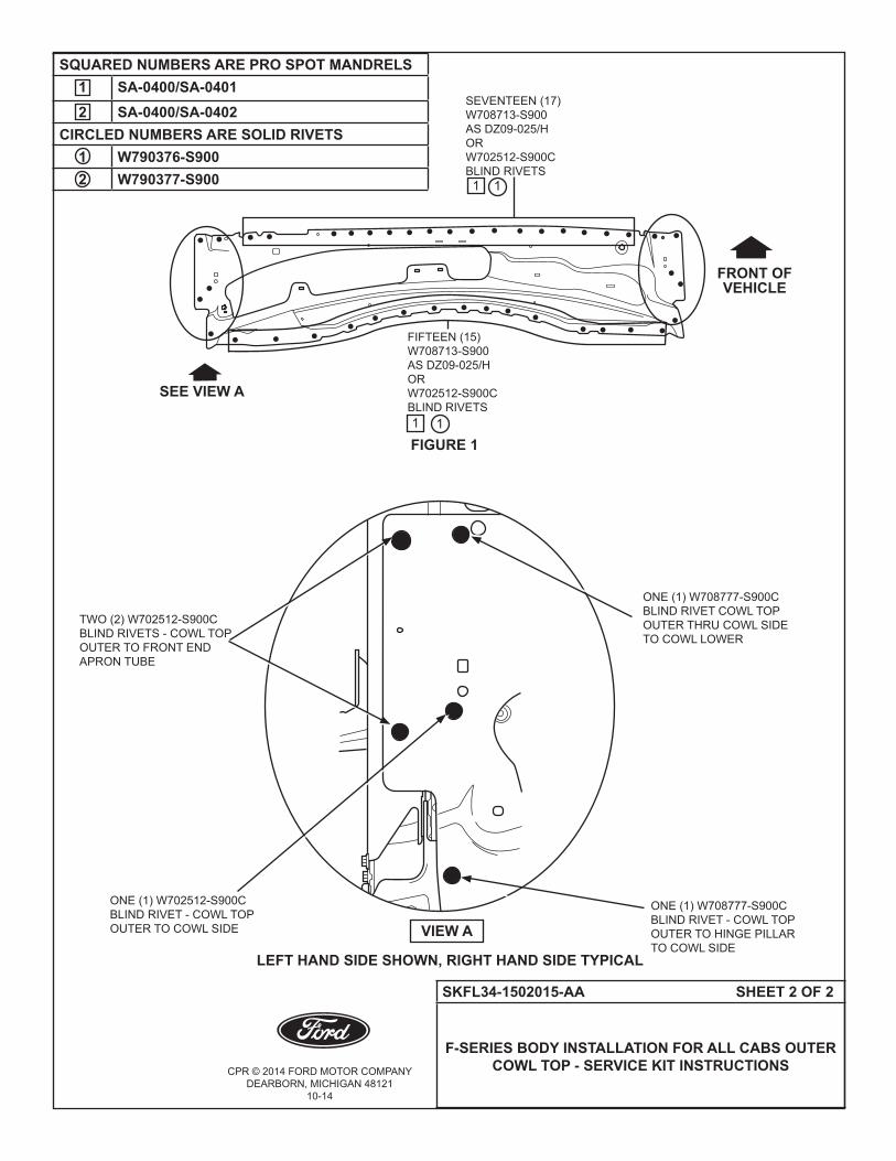
CPR © 2014 FORD MOTOR COMPANYDEARBORN, MICHIGAN 48121
10-14
SKFL34-1502015-AA SHEET 2 OF 2
F-SERIES BODY INSTALLATION FOR ALL CABS OUTER COWL TOP - SERVICE KIT INSTRUCTIONS
FIGURE 1
ONE (1) W708777-S900C BLIND RIVET - COWL TOP OUTERTOHINGEPILLARTO COWL SIDE
FRONT OFVEHICLE
SEE VIEW A
VIEW A
ONE (1) W708777-S900C BLIND RIVET COWL TOP OUTERTHRUCOWLSIDETO COWL LOWER
ONE (1) W702512-S900C BLIND RIVET - COWL TOP OUTERTOCOWLSIDE
TWO (2) W702512-S900C BLIND RIVETS - COWL TOP OUTERTOFRONTENDAPRONTUBE
1
LEFT HAND SIDE SHOWN, RIGHT HAND SIDE TYPICAL
SEVENTEEN (17)W708713-S900 AS DZ09-025/HOR W702512-S900C BLIND RIVETS
FIFTEEN (15)W708713-S900 AS DZ09-025/HOR W702512-S900C BLIND RIVETS1
SQUARED NUMBERS ARE PRO SPOT MANDRELS1 SA-0400/SA-04012 SA-0400/SA-0402
CIRCLED NUMBERS ARE SOLID RIVETS1 W790376-S9002 W790377-S900 1
1

CPR © 2014 FORD MOTOR COMPANYDEARBORN, MICHIGAN 48121
10-14
SKFL34-1610142-AA SHEET 1 OF 3
F-SERIES BODY INSTALLATION FOR CREW CAB OUTER ROCKER PANEL REINFORCEMENT -
SERVICE KIT INSTRUCTIONS
F-SERIES BODY INSTALLATION FOR CREW CAB OUTER ROCKER PANEL REINFORCEMENT - SERVICE KIT INSTRUCTIONS
KIT Part Number Description Quantity
FL34-1610142-AB Outer Rocker Panel Reinforcement Forward (RH) - Crew Cab 1
SKFL34-1610142-AA Instruction Sheet 1
KIT Part Number Description Quantity
FL34-1610402-AB Outer Rocker Panel Reinforcement Rear (RH) - Crew Cab 1
SKFL34-1610142-AA Instruction Sheet 1
KIT Part Number Description Quantity
FL34-1610143-AB Outer Rocker Panel Reinforcement Forward (LH) - Crew Cab 1
SKFL34-1610142-AA Instruction Sheet 1
KIT Part Number Description Quantity
FL34-1610403-AB Outer Rocker Panel Reinforcement Rear (LH) - Crew Cab 1
SKFL34-1610142-AA Instruction Sheet 1
NOT INCLUDED IN KIT (PROCURE LOCALLY)Part Number Description Quantity
W702512-S900C Blind Rivet 21W708777-S900C Blind Rivet 7W710246-S900 Self-Piercing Rivet (SPR) Code DB 5Motorcraft TA-1, 3M 8115 or Fusor 108B
Metal Panel Bonding Adhesive 1
CPR © 2014 FORD MOTOR COMPANYDEARBORN, MICHIGAN 48121
10-14
SKFL34-1610142-AA SHEET 2 OF 3
F-SERIES BODY INSTALLATION FOR CREW CAB OUTER ROCKER PANEL REINFORCEMENT -
SERVICE KIT INSTRUCTIONS
SERVICE GUIDELINES:
• Aluminumrepairsshouldbeperformedinanareaprotectedfromsteelworkingareas,andtoolsusedin aluminumrepairshouldbequarantinedfromsteelrepairtools. • ReplacementSelf-PiercingRivets(SPRs)arethepreferredreplacementduringrepairfororiginalSPR locations,wherefeasible.BlindrivetsarethenextpreferredreplacementfororiginalSPRs.Insomecases,solid rivetsmayalsobeusedasareplacementforSPRs.Thefigureswillexplicitlycalloutwhichrivetsarepossible. • ReplacementSPRsaretobeinstalledadjacenttooriginalSPRlocation.
NOTE: Do not install replacement SPR in original SPR hole.
• BlindrivetsmaybeinstalledinoriginalSPRholes,aftertheyarereamedoutto6.5mm.Besuretogrindall surfacesoftheflangesmoothpriortoblindrivetinstallationinoriginalSPRlocations.
• FlowDrillScrews(FDS)aretobereplacedbyblindrivetsonly.TheoriginallocationoftheFDSisused,but reamedoutto6.5mm.
• Rivetsmayberemovedbydrilling,grinding,orSPRgunsetupasarivetremovaltool.
• Usingheat(notexceeding425°F)toloosenarivetbondedpanelshouldonlybedonewhenallpanelsinthe jointwillbereplacedorseparatedandnewadhesiveapplied.
• Flangepreparationforadhesiveistogrindtocleanmetalwith80-120grit,clean,andthenapplytheadhesive, spreadingitoutwithanacidbrush,coveringanyexposedaluminum.
• Clecosareanexcellentwaytoholdthepanelsintopositionwhenfittinganddrillingrivetholes.
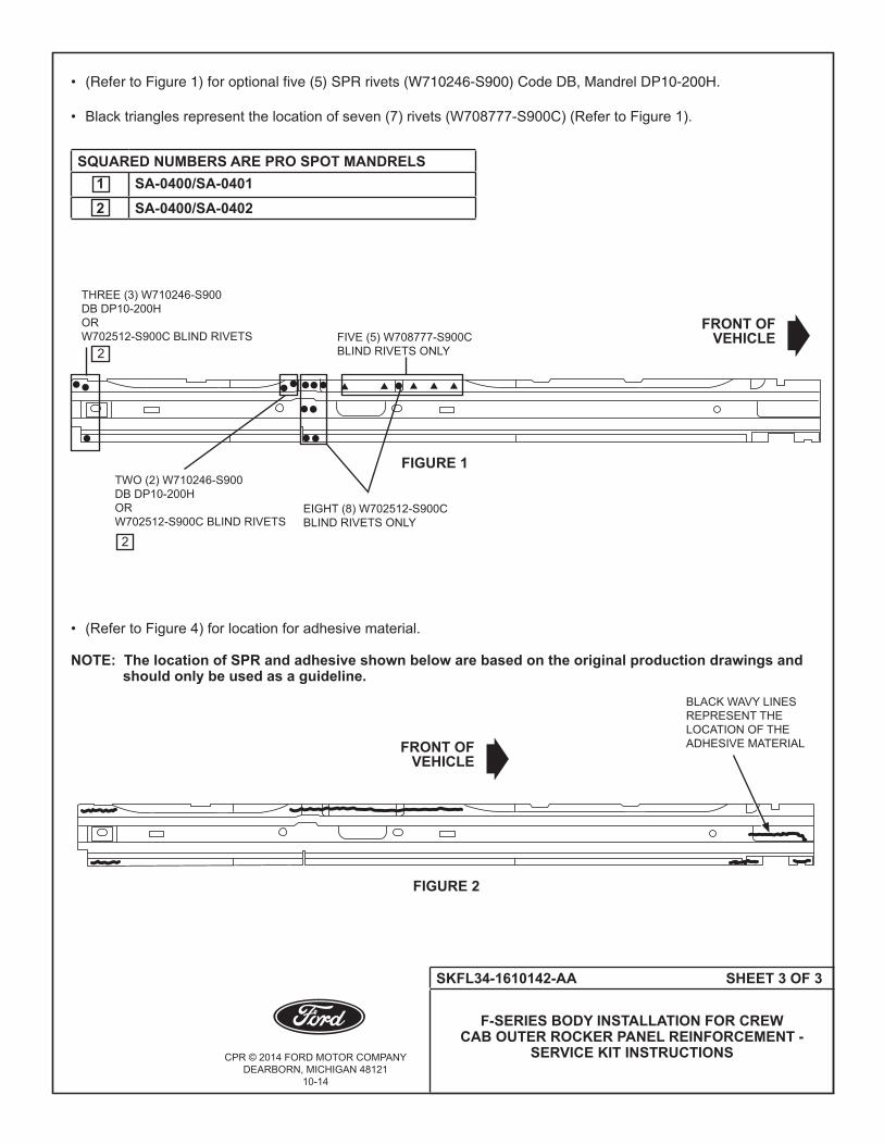
CPR © 2014 FORD MOTOR COMPANYDEARBORN, MICHIGAN 48121
10-14
SKFL34-1610142-AA SHEET 3 OF 3
F-SERIES BODY INSTALLATION FOR CREW CAB OUTER ROCKER PANEL REINFORCEMENT -
SERVICE KIT INSTRUCTIONS
•(Refer to Figure 1) for optional five (5) SPR rivets (W710246-S900) Code DB, Mandrel DP10-200H.
• Blacktrianglesrepresentthelocationofseven(7)rivets(W708777-S900C)(RefertoFigure1).
• (RefertoFigure4)forlocationforadhesivematerial. NOTE: The location of SPR and adhesive shown below are based on the original production drawings and should only be used as a guideline.
FIGURE 1
FRONT OFVEHICLE
THREE (3) W710246-S900 DB DP10-200HORW702512-S900C BLIND RIVETS FIVE (5) W708777-S900C
BLIND RIVETS ONLY
EIGHT (8) W702512-S900C BLIND RIVETS ONLY
TWO (2) W710246-S900 DB DP10-200HORW702512-S900C BLIND RIVETS
SQUARED NUMBERS ARE PRO SPOT MANDRELS1 SA-0400/SA-04012 SA-0400/SA-0402
2
2
BLACK WAVY LINES REPRESENT THE LOCATION OF THE ADHESIVE MATERIAL
FIGURE 2
FRONT OFVEHICLE

CPR © 2014 FORD MOTOR COMPANYDEARBORN, MICHIGAN 48121
10-14
SKFL34-95280A54-AA SHEET 1 OF 4
F-SERIES ALL CABS PANEL ASSEMBLY BOX SIDE INNER - SERVICE KIT INSTRUCTIONS
F-SERIES ALL CABS PANEL ASSEMBLY BOX SIDE INNER - SERVICE KIT INSTRUCTIONS
KITPart Number Description Quantity
FL34-95280A54-AK Box Inner Side Panel 5.5' (RH) 1SKFL34-95280A54-AA Instruction Sheet 1
NOT INCLUDED IN KIT (PROCURE LOCALLY)Part Number Description Quantity
W707638-S900C Blind Rivet 24Motorcraft TA-1, 3M 8115 or Fusor 108B
Metal Panel Bonding Adhesive 1
KITPart Number Description Quantity
FL34-95280A55-AK Box Inner Side Panel 5.5' (LH) 1SKFL34-95280A54-AA Instruction Sheet 1
NOT INCLUDED IN KIT (PROCURE LOCALLY)Part Number Description Quantity
W707638-S900C Blind Rivet 24Motorcraft TA-1, 3M 8115 or Fusor 108B
Metal Panel Bonding Adhesive 1
KIT Part Number Description Quantity
FL34-96280A54-AL Box Inner Side Panel 6.5' (RH) 1SKFL34-95280A54-AA Instruction Sheet 1
NOT INCLUDED IN KIT (PROCURE LOCALLY)Part Number Description Quantity
W707638-S900C Blind Rivet 28W702512-S900C Blind Rivet 2Motorcraft TA-1, 3M 8115 or Fusor 108B
Metal Panel Bonding Adhesive 1
KIT Part Number Description Quantity
FL34-96280A55-AL Box Inner Side Panel 6.5' (LH) 1SKFL34-95280A54-AA Instruction Sheet 1
NOT INCLUDED IN KIT (PROCURE LOCALLY)Part Number Description Quantity
W707638-S900C Blind Rivet 28W702512-S900C Blind Rivet 2Motorcraft TA-1, 3M 8115 or Fusor 108B
Metal Panel Bonding Adhesive 1

CPR © 2014 FORD MOTOR COMPANYDEARBORN, MICHIGAN 48121
10-14
SKFL34-95280A54-AA SHEET 2 OF 4
F-SERIES ALL CABS PANEL ASSEMBLY BOX SIDE INNER - SERVICE KIT INSTRUCTIONS
KIT Part Number Description Quantity
FL34-98280A54-AM Box Inner Side Panel 8.0' (RH) 1SKFL34-95280A54-AA Instruction Sheet 1
NOT INCLUDED IN KIT (PROCURE LOCALLY)Part Number Description Quantity
W707638-S900C Blind Rivet 34W702512-S900C Blind Rivet 2Motorcraft TA-1, 3M 8115 or Fusor 108B
Metal Panel Bonding Adhesive 1
KITPart Number Description Quantity
FL34-98280A55-AM Box Inner Side Panel 8.0' (LH) 1SKFL34-95280A54-AA Instruction Sheet 1
NOT INCLUDED IN KIT (PROCURE LOCALLY)Part Number Description Quantity
W707638-S900C Blind Rivet 34W702512-S900C Blind Rivet 2Motorcraft TA-1, 3M 8115 or Fusor 108B
Metal Panel Bonding Adhesive 1

CPR © 2014 FORD MOTOR COMPANYDEARBORN, MICHIGAN 48121
10-14
SKFL34-95280A54-AA SHEET 3 OF 4
F-SERIES ALL CABS PANEL ASSEMBLY BOX SIDE INNER - SERVICE KIT INSTRUCTIONS
SERVICE GUIDELINES:
• Aluminumrepairsshouldbeperformedinanareaprotectedfromsteelworkingareas,andtoolsusedin aluminumrepairshouldbequarantinedfromsteelrepairtools. • ReplacementSelf-PiercingRivets(SPRs)arethepreferredreplacementduringrepairfororiginalSPR locations,wherefeasible.BlindrivetsarethenextpreferredreplacementfororiginalSPRs.Insomecases,solid rivetsmayalsobeusedasareplacementforSPRs.Thefigureswillexplicitlycalloutwhichrivetsarepossible. • ReplacementSPRsaretobeinstalledadjacenttooriginalSPRlocation.
NOTE: Do not install replacement SPR in original SPR hole.
• BlindrivetsmaybeinstalledinoriginalSPRholes,aftertheyarereamedoutto6.5mm.Besuretogrindall surfacesoftheflangesmoothpriortoblindrivetinstallationinoriginalSPRlocations.
• FlowDrillScrews(FDS)aretobereplacedbyblindrivetsonly.TheoriginallocationoftheFDSisused,but reamedoutto6.5mm.
• Rivetsmayberemovedbydrilling,grinding,orSPRgunsetupasarivetremovaltool.
• Usingheat(notexceeding425°F)toloosenarivetbondedpanelshouldonlybedonewhenallpanelsinthe jointwillbereplacedorseparatedandnewadhesiveapplied.
• Flangepreparationforadhesiveistogrindtocleanmetalwith80-120grit,clean,andthenapplytheadhesive, spreadingitoutwithanacidbrush,coveringanyexposedaluminum.
• Clecosareanexcellentwaytoholdthepanelsintopositionwhenfittinganddrillingrivetholes.
• Blackdotsrepresentthelocationoftwelve(12)blindrivets(W707638-S900C).(RefertoFigure1).
•Blackdotsrepresentthelocationofeight(8)blindrivets(W707638-S900C).(RefertoFigure2).
FIGURE 1 FIGURE 2
FRONT OFVEHICLE
FRONT OFVEHICLE
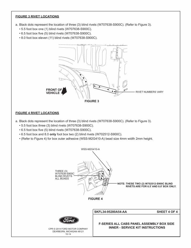
CPR © 2014 FORD MOTOR COMPANYDEARBORN, MICHIGAN 48121
10-14
SKFL34-95280A54-AA SHEET 4 OF 4
F-SERIES ALL CABS PANEL ASSEMBLY BOX SIDE INNER - SERVICE KIT INSTRUCTIONS
FIGURE 3 RIVET LOCATIONS
a. Blackdotsrepresentthelocationofthree(3)blindrivets(W707638-S900C).(RefertoFigure3). •5.5footboxone(1)blindrivets(W707638-S900C). •6.5footboxfive(5)blindrivets(W707638-S900C). •8.0footboxeleven(11)blindrivets(W707638-S900C).
FIGURE 4 RIVET LOCATIONS
a. Blackdotsrepresentthelocationofthree(3)blindrivets(W707638-S900C).(RefertoFigure3). •5.5footboxthree(3)blindrivets(W707638-S900C). •6.5footboxfive(5)blindrivets(W707638-S900C). •6.5footboxand8.0onlyfootboxtwo(2)blindrivets(W702512-S900C). •(RefertoFigure4)forboxouteradhesive(WSS-M2G410-A)beadsize4mmwidth2mmheight.
FIGURE 3
FIGURE 4
WSS-M2G410-A
FRONT OFVEHICLE
THREE (3)W707638-S900CBLIND RIVETSALL BOXES
NOTE: THESE TWO (2) W702512-S900C BLIND RIVETS ARE FOR 6.5' AND 8.0' BOX ONLY.
RIVETNUMBERSVARY

CPR © 2014 FORD MOTOR COMPANYDEARBORN, MICHIGAN 48121
10-14
SKFL34-9511215-AA SHEET 1 OF 3
F-SERIES PICKUP BOX FLOOR
F-SERIES PICKUP BOX FLOOR SERVICE KIT INSTRUCTIONS
KITPart Number Description Quantity
FL34-9511215-BB Pan Assembly Rear Floor - 5.5' Box 1SKFL34-9511215-AA Instruction Sheet 1
NOT INCLUDED IN KIT (PROCURE LOCALLY)Part Number Description Quantity
W707638-S900C Blind Rivet 17W702512-S900C Blind Rivet 28W708777-S900C Blind Rivet 14W702554-S900C Blind Rivet 8Motorcraft TA-1, 3M 8115 or Fusor 108B
Metal Panel Bonding Adhesive 1
KITPart Number Description Quantity
FL34-9611215-BB Pan Assembly Rear Floor - 6.5' Box 1SKFL34-9511215-AA Instruction Sheet 1
NOT INCLUDED IN KIT (PROCURE LOCALLY)Part Number Description Quantity
W707638-S900C Blind Rivet 17W702512-S900C Blind Rivet 32W708777-S900C Blind Rivet 14W702554-S900C Blind Rivet 8Motorcraft TA-1, 3M 8115 or Fusor 108B
Metal Panel Bonding Adhesive 1
KIT Part Number Description Quantity
FL34-9811215-BB Pan Assembly Rear Floor - 8.0' Box 1SKFL34-9511215-AA Instruction Sheet 1
NOT INCLUDED IN KIT (PROCURE LOCALLY)Part Number Description Quantity
W707638-S900C Blind Rivet 17W702512-S900C Blind Rivet 36W708777-S900C Blind Rivet 14W702554-S900C Blind Rivet 8Motorcraft TA-1, 3M 8115 or Fusor 108B
Metal Panel Bonding Adhesive 1
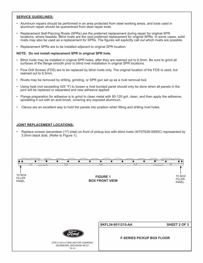
CPR © 2014 FORD MOTOR COMPANYDEARBORN, MICHIGAN 48121
10-14
SKFL34-9511215-AA SHEET 2 OF 3
F-SERIES PICKUP BOX FLOOR
SERVICE GUIDELINES:
• Aluminumrepairsshouldbeperformedinanareaprotectedfromsteelworkingareas,andtoolsusedin aluminumrepairshouldbequarantinedfromsteelrepairtools. • ReplacementSelf-PiercingRivets(SPRs)arethepreferredreplacementduringrepairfororiginalSPR locations,wherefeasible.BlindrivetsarethenextpreferredreplacementfororiginalSPRs.Insomecases,solid rivetsmayalsobeusedasareplacementforSPRs.Thefigureswillexplicitlycalloutwhichrivetsarepossible. • ReplacementSPRsaretobeinstalledadjacenttooriginalSPRlocation.
NOTE: Do not install replacement SPR in original SPR hole.
• BlindrivetsmaybeinstalledinoriginalSPRholes,aftertheyarereamedoutto6.5mm.Besuretogrindall surfacesoftheflangesmoothpriortoblindrivetinstallationinoriginalSPRlocations.
• FlowDrillScrews(FDS)aretobereplacedbyblindrivetsonly.TheoriginallocationoftheFDSisused,but reamed out to 6.5mm.
• Rivetsmayberemovedbydrilling,grinding,orSPRgunsetupasarivetremovaltool.
• Usingheat(notexceeding425°F)toloosenarivetbondedpanelshouldonlybedonewhenallpanelsinthe jointwillbereplacedorseparatedandnewadhesiveapplied.
• Flangepreparationforadhesiveistogrindtocleanmetalwith80-120grit,clean,andthenapplytheadhesive, spreadingitoutwithanacidbrush,coveringanyexposedaluminum.
• Clecosareanexcellentwaytoholdthepanelsintopositionwhenfittinganddrillingrivetholes.
JOINT REPLACEMENT LOCATIONS:
• Replacescrews(seventeen(17)total)onfrontofpickupboxwithblindrivets(W707638-S900C)representedby 3.0mmblackdots.(RefertoFigure1).
FIGURE 1BOX FRONT VIEW
TO BOX FILLER PANEL
TO BOX FILLER PANEL
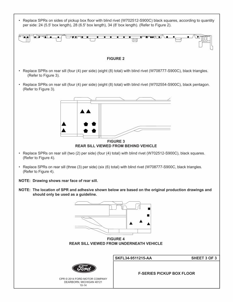
CPR © 2014 FORD MOTOR COMPANYDEARBORN, MICHIGAN 48121
10-14
SKFL34-9511215-AA SHEET 3 OF 3
F-SERIES PICKUP BOX FLOOR
• ReplaceSPRsonsidesofpickupboxfloorwithblindrivet(W702512-S900C)blacksquares,accordingtoquantity perside:24(5.5'boxlength),28(6.5'boxlength),34(8'boxlength).(RefertoFigure2).
• ReplaceSPRsonrearsill(four(4)perside)(eight(8)total)withblindrivet(W708777-S900C),blacktriangles. (RefertoFigure3). • ReplaceSPRsonrearsill(four(4)perside)(eight(8)total)withblindrivet(W702554-S900C),blackpentagon. (RefertoFigure3).
• ReplaceSPRsonrearsill(two(2)perside)(four(4)total)withblindrivet(W702512-S900C),blacksquares. (RefertoFigure4). • ReplaceSPRsonrearsill(three(3)perside)(six(6)total)withblindrivet(W708777-S900C,blacktriangles. (RefertoFigure4). NOTE: Drawing shows rear face of rear sill.
NOTE: The location of SPR and adhesive shown below are based on the original production drawings and should only be used as a guideline.
FIGURE 2
FIGURE 3REAR SILL VIEWED FROM BEHIND VEHICLE
FIGURE 4REAR SILL VIEWED FROM UNDERNEATH VEHICLE

CPR © 2014 FORD MOTOR COMPANYDEARBORN, MICHIGAN 48121
10-14
SKFL34-1527846-AA SHEET 1 OF 2
F-SERIES BODY INSTALLATION FORREAR BODY FILLER PANEL PANEL -
SERVICE KIT INSTRUCTIONS FOR ALL CABS
F-SERIES BODY INSTALLATION FOR REAR BODY FILLER PANEL - SERVICE KIT INSTRUCTIONS FOR ALL CABS
KITPart Number Description Quantity
FL34-1527846-AB Rear Body Filler Panel - (RH) 1SKFL34-1527846-AA Instruction Sheet 1
KITPart Number Description Quantity
FL34-1527847-AB Rear Body Filler Panel - (LH) 1SKFL34-1527846-AA Instruction Sheet 1
NOT INCLUDED IN KIT (PROCURE LOCALLY)Part Number Description Quantity
W707638-S900C Blind Rivet 5Motorcraft TA-1, 3M 8115 or Fusor 108B
Metal Panel Bonding Adhesive 1
SERVICE GUIDELINES:
• Aluminumrepairsshouldbeperformedinanareaprotectedfromsteelworkingareas,andtoolsusedin aluminumrepairshouldbequarantinedfromsteelrepairtools. • ReplacementSelf-PiercingRivets(SPRs)arethepreferredreplacementduringrepairfororiginalSPR locations,wherefeasible.BlindrivetsarethenextpreferredreplacementfororiginalSPRs.Insomecases,solid rivetsmayalsobeusedasareplacementforSPRs.Thefigureswillexplicitlycalloutwhichrivetsarepossible. • ReplacementSPRsaretobeinstalledadjacenttooriginalSPRlocation.
NOTE: Do not install replacement SPR in original SPR hole.
• BlindrivetsmaybeinstalledinoriginalSPRholes,aftertheyarereamedoutto6.5mm.Besuretogrindall surfacesoftheflangesmoothpriortoblindrivetinstallationinoriginalSPRlocations.
• FlowDrillScrews(FDS)aretobereplacedbyblindrivetsonly.TheoriginallocationoftheFDSisused,but reamedoutto6.5mm.
• Rivetsmayberemovedbydrilling,grinding,orSPRgunsetupasarivetremovaltool.
• Usingheat(notexceeding425°F)toloosenarivetbondedpanelshouldonlybedonewhenallpanelsinthe jointwillbereplacedorseparatedandnewadhesiveapplied.
• Flangepreparationforadhesiveistogrindtocleanmetalwith80-120grit,clean,andthenapplytheadhesive, spreadingitoutwithanacidbrush,coveringanyexposedaluminum.
• Clecosareanexcellentwaytoholdthepanelsintopositionwhenfittinganddrillingrivetholes.

CPR © 2014 FORD MOTOR COMPANYDEARBORN, MICHIGAN 48121
10-14
SKFL34-1527846-AA SHEET 2 OF 2
F-SERIES BODY INSTALLATION FORREAR BODY FILLER PANEL PANEL -
SERVICE KIT INSTRUCTIONS FOR ALL CABS
•Blackdotsrepresentthelocationoffive(5)blindrivets(W707638-S900C).(RefertoFigure1).
FIGURE 1 FIGURE 2
BLACK WAVY LINES REPRESENT THE LOCATION OF THE ADHESIVE MATERIAL

CPR © 2016 FORD MOTOR COMPANYDEARBORN, MICHIGAN 48121
8-16
SKFL34-1624704-AC SHEET 1 OF 3
F-SERIES CREW CAB REAR DOOR OUTER PANEL INSTALLATION - SERVICE KIT INSTRUCTIONS
F-SERIES CREW CAB REAR DOOR OUTER PANEL INSTALLATION - SERVICE KIT INSTRUCTIONS
KITPart Number Description Quantity
FL34-1624704-A* Rear Door Outer Panel Crew Cab - (RH) 1SKFL34-1624704-AC Instruction Sheet 1
KITPart Number Description Quantity
FL34-1624705-A* Rear Door Outer Panel Crew Cab - (LH) 1SKFL34-1624704-AC Instruction Sheet 1
NOT INCLUDED IN KIT (PROCURE LOCALLY)Part Number Description Quantity
W790376-S900 Solid Rivet 8W708717-S900 SPR Rivet Code AW 8Rotunda 501-078-2 Hem Opening Tools (LH) 1Rotunda 501-078-1 Hem Opening Tools (RH) 1501-080 Hem Closing Tool 1Motorcraft TA-1, 3M 8115 or Fusor 108B
Metal Panel Bonding Adhesive 1
SERVICE GUIDELINES:
1. Aluminum repairs should be performed in an area protected from steel working areas, and tools used in aluminum repair should be quarantined from steel repair tools.
2. Any rivets on bottom door hem are for original manufacturer purposes only and are not replaced during the service door outer panel replacement procedure. 3. Remove the door trim panel from the affected door and window glass. For additional information, refer to Section 501-11.
4. Remove the outside door handle. For additional information, refer to Section 501-09.
5. Remove door trim including mouldings and weatherstrips.
6. Remove the door assembly and secure on a workstand.
7. Remove all SPR rivets outlined at door shut face, insert TOOL 501-078-1 (RH) or TOOL 501-078-2 (LH) in an air impact gun (620 kPa (90 psi) air pressure is required for consistent tool operation). Using the tool, open the hem flangearoundtheperimeterofthepanel.
NOTE: The use of a heat gun may be required to soften door panel adhesive.
8. Useasharpknifetocuttheadhesivebetweenthedoorouteroriginalpanel,flutterbeam,beltlinereinforcement and intrusion beam.
9. Remove original door outer panel.

CPR © 2016 FORD MOTOR COMPANYDEARBORN, MICHIGAN 48121
8-16
SKFL34-1624704-AC SHEET 2 OF 3
F-SERIES CREW CAB REAR DOOR OUTER PANEL INSTALLATION - SERVICE KIT INSTRUCTIONS
10. Scuff sand only, DO NOT GRIND, the inner structure bonding surfaces. Do not sand to bare substrate, leave original e-coat as intact as possible.
11. Trialfittheservicereplacementpaneltothedoorshellassembly.
12. Temporarily secure the outer panel to the door assembly and install on the vehicle to verify proper skin alignment.
13. Use reference marks to assist. 14. Scuff the replacement skin bonding areas, then clean with adhesive cleaner. 15.Applymetalbondingadhesivetothefollowingareas:servicereplacementhemflange,flutterbeam-to-outer panel,andouterbeltreinforcement-to-outerpanel.(Refertofigure1).
16. Using a 501-080 Hem Closing Tool or the hammer and dolly method, close the perimeter door hem and smooth any residual adhesive in the joints. 17. Install eight (8) (W708717) SPR rivets code AW or eight (8) W790376-S900 solid rivets. (Refer to Figure 2). 18 Prime and Paint the door following Ford approved paint company materials/guidelines. 19. Install the door to the vehicle, align, and reassemble all components. 20. Apply anti-corrosion treatments as outlined in workshop manual section 501-35.
21. (Refer to Figure 1) for location for adhesive material.
NOTE: The location of SPR and adhesive shown below are based on the original production drawings and should only be used as a guideline. (Refer to Figure 1).
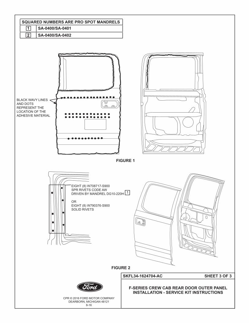
CPR © 2016 FORD MOTOR COMPANYDEARBORN, MICHIGAN 48121
8-16
SKFL34-1624704-AC SHEET 3 OF 3
F-SERIES CREW CAB REAR DOOR OUTER PANEL INSTALLATION - SERVICE KIT INSTRUCTIONS
FIGURE 2
FIGURE 1
BLACK WAVY LINES AND DOTSREPRESENT THE LOCATION OF THE ADHESIVE MATERIAL
EIGHT (8) W708717-S900 SPR RIVETS CODE AW DRIVEN BY MANDREL DG10-220H
OR EIGHT (8) W790376-S900 SOLID RIVETS
SQUARED NUMBERS ARE PRO SPOT MANDRELS1 SA-0400/SA-04012 SA-0400/SA-0402
1

CPR © 2014 FORD MOTOR COMPANYDEARBORN, MICHIGAN 48121
10-14
SKFL34-15107A94-AA SHEET 1 OF 2
F-SERIES REAR FLOOR CROSSMEMBER INSTALLATION - SERVICE KIT INSTRUCTIONS
FOR ALL CABS
F-SERIES REAR FLOOR CROSSMEMBER INSTALLATION - SERVICE KIT INSTRUCTIONS FOR ALL CABS
KIT Part Number Description Quantity
FL34-15107A94-AF Rear Floor Sill Cross Member - Regular Cab 1SKFL34-15107A94-AA Instruction Sheet 1
KIT Part Number Description Quantity
FL34-16107A94-AF Rear Floor Sill Cross Member - Crew Cab/Super Cab 1SKFL34-15107A94-AA Instruction Sheet 1
NOT INCLUDED IN KIT (PROCURE LOCALLY)Part Number Description Quantity
W702512-S900C Blind Rivet 40W708777-S900C Blind Rivet 16Motorcraft TA-1, 3M 8115 or Fusor 108B
Metal Panel Bonding Adhesive 1
SERVICE GUIDELINES:
• Aluminumrepairsshouldbeperformedinanareaprotectedfromsteelworkingareas,andtoolsusedin aluminum repair should be quarantined from steel repair tools. • ReplacementSelf-PiercingRivets(SPRs)arethepreferredreplacementduringrepairfororiginalSPR locations, where feasible. Blind rivets are the next preferred replacement for original SPRs. In some cases, solid rivetsmayalsobeusedasareplacementforSPRs.Thefigureswillexplicitlycalloutwhichrivetsarepossible. • ReplacementSPRsaretobeinstalledadjacenttooriginalSPRlocation.
NOTE: Do not install replacement SPR in original SPR hole.
• BlindrivetsmaybeinstalledinoriginalSPRholes,aftertheyarereamedoutto6.5mm.Besuretogrindall surfacesoftheflangesmoothpriortoblindrivetinstallationinoriginalSPRlocations.
• FlowDrillScrews(FDS)aretobereplacedbyblindrivetsonly.TheoriginallocationoftheFDSisused,but reamed out to 6.5mm.
• Rivetsmayberemovedbydrilling,grinding,orSPRgunsetupasarivetremovaltool.
• Usingheat(notexceeding425°F)toloosenarivetbondedpanelshouldonlybedonewhenallpanelsinthe jointwillbereplacedorseparatedandnewadhesiveapplied.
• Flangepreparationforadhesiveistogrindtocleanmetalwith80-120grit,clean,andthenapplytheadhesive, spreading it out with an acid brush, covering any exposed aluminum.
• Clecosareanexcellentwaytoholdthepanelsintopositionwhenfittinganddrillingrivetholes

CPR © 2014 FORD MOTOR COMPANYDEARBORN, MICHIGAN 48121
10-14
SKFL34-15107A94-AA SHEET 2 OF 2
F-SERIES REAR FLOOR CROSSMEMBER INSTALLATION - SERVICE KIT INSTRUCTIONS
FOR ALL CABS
•Blackdotsrepresentthelocationofeight(8)blindrivets(W708777-S900C)tosidesill.(RefertoFigure1).
•Blacksquaresrepresentthelocationofforty(40)blindrivets(W702512-S900C)tofloorpan.(RefertoFigure2). NOTE: The location of SPR and adhesive shown below are based on the original production drawings and should only be used as a guideline. (Refer to Figure 2).
FIGURE 1
FIGURE 2
FIGURE 3
FIGURE 4
BLACK WAVY LINES REPRESENT THE LOCATION OF THE ADHESIVE MATERIAL

CPR © 2014 FORD MOTOR COMPANYDEARBORN, MICHIGAN 48121
10-14
SKFL34-1540520-AA SHEET 1 OF 2
F-SERIES BODY INSTALLATION FOR REAR HEADER ALL CABS -
SERVICE KIT INSTRUCTIONS
F-SERIES BODY INSTALLATION FOR REAR HEADER ALL CABS - SERVICE KIT INSTRUCTIONS
KIT Part Number Description Quantity
FL34-1540520-AE Upper Rear Header Panel 1SKFL34-1540520-AA Instruction Sheet 1
NOT INCLUDED IN KIT (PROCURE LOCALLY)Part Number Description Quantity
W707638-S900C Blind Rivet 10Motorcraft TA-1, 3M 8115 or Fusor 108B
Metal Panel Bonding Adhesive 1
SERVICE GUIDELINES:
• Aluminumrepairsshouldbeperformedinanareaprotectedfromsteelworkingareas,andtoolsusedin aluminumrepairshouldbequarantinedfromsteelrepairtools. • ReplacementSelf-PiercingRivets(SPRs)arethepreferredreplacementduringrepairfororiginalSPR locations,wherefeasible.BlindrivetsarethenextpreferredreplacementfororiginalSPRs.Insomecases,solid rivetsmayalsobeusedasareplacementforSPRs.Thefigureswillexplicitlycalloutwhichrivetsarepossible. • ReplacementSPRsaretobeinstalledadjacenttooriginalSPRlocation.
NOTE: Do not install replacement SPR in original SPR hole.
• BlindrivetsmaybeinstalledinoriginalSPRholes,aftertheyarereamedoutto6.5mm.Besuretogrindall surfacesoftheflangesmoothpriortoblindrivetinstallationinoriginalSPRlocations.
• FlowDrillScrews(FDS)aretobereplacedbyblindrivetsonly.TheoriginallocationoftheFDSisused,but reamedoutto6.5mm.
• Rivetsmayberemovedbydrilling,grinding,orSPRgunsetupasarivetremovaltool.
• Usingheat(notexceeding425°F)toloosenarivetbondedpanelshouldonlybedonewhenallpanelsinthe jointwillbereplacedorseparatedandnewadhesiveapplied.
• Flangepreparationforadhesiveistogrindtocleanmetalwith80-120grit,clean,andthenapplytheadhesive, spreadingitoutwithanacidbrush,coveringanyexposedaluminum.
• Clecosareanexcellentwaytoholdthepanelsintopositionwhenfittinganddrillingrivetholes.

CPR © 2014 FORD MOTOR COMPANYDEARBORN, MICHIGAN 48121
10-14
SKFL34-1540520-AA SHEET 2 OF 2
F-SERIES BODY INSTALLATION FOR REAR HEADER ALL CABS -
SERVICE KIT INSTRUCTIONS
• Blackdotsrepresentthelocationoftheten(10)blindrivets(W707638-S900C).
• (RefertoFigure2)forlocationforadhesivematerial. NOTE: The location of SPR and adhesive shown below are based on the original production drawings and should only be used as a guideline.
FIGURE 1
FIGURE 2
BLACK WAVY LINES REPRESENT THE LOCATION OF THE ADHESIVE MATERIAL
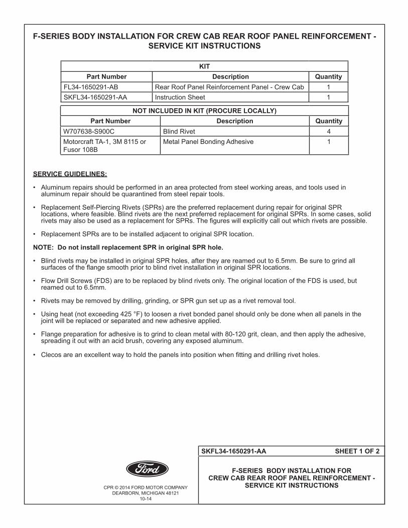
CPR © 2014 FORD MOTOR COMPANYDEARBORN, MICHIGAN 48121
10-14
SKFL34-1650291-AA SHEET 1 OF 2
F-SERIES BODY INSTALLATION FOR CREW CAB REAR ROOF PANEL REINFORCEMENT -
SERVICE KIT INSTRUCTIONS
F-SERIES BODY INSTALLATION FOR CREW CAB REAR ROOF PANEL REINFORCEMENT - SERVICE KIT INSTRUCTIONS
KITPart Number Description Quantity
FL34-1650291-AB Rear Roof Panel Reinforcement Panel - Crew Cab 1SKFL34-1650291-AA Instruction Sheet 1
NOT INCLUDED IN KIT (PROCURE LOCALLY)Part Number Description Quantity
W707638-S900C Blind Rivet 4Motorcraft TA-1, 3M 8115 or Fusor 108B
Metal Panel Bonding Adhesive 1
SERVICE GUIDELINES:
• Aluminumrepairsshouldbeperformedinanareaprotectedfromsteelworkingareas,andtoolsusedin aluminumrepairshouldbequarantinedfromsteelrepairtools. • ReplacementSelf-PiercingRivets(SPRs)arethepreferredreplacementduringrepairfororiginalSPR locations,wherefeasible.BlindrivetsarethenextpreferredreplacementfororiginalSPRs.Insomecases,solid rivetsmayalsobeusedasareplacementforSPRs.Thefigureswillexplicitlycalloutwhichrivetsarepossible. • ReplacementSPRsaretobeinstalledadjacenttooriginalSPRlocation.
NOTE: Do not install replacement SPR in original SPR hole.
• BlindrivetsmaybeinstalledinoriginalSPRholes,aftertheyarereamedoutto6.5mm.Besuretogrindall surfacesoftheflangesmoothpriortoblindrivetinstallationinoriginalSPRlocations.
• FlowDrillScrews(FDS)aretobereplacedbyblindrivetsonly.TheoriginallocationoftheFDSisused,but reamedoutto6.5mm.
• Rivetsmayberemovedbydrilling,grinding,orSPRgunsetupasarivetremovaltool.
• Usingheat(notexceeding425°F)toloosenarivetbondedpanelshouldonlybedonewhenallpanelsinthe jointwillbereplacedorseparatedandnewadhesiveapplied.
• Flangepreparationforadhesiveistogrindtocleanmetalwith80-120grit,clean,andthenapplytheadhesive, spreadingitoutwithanacidbrush,coveringanyexposedaluminum.
• Clecosareanexcellentwaytoholdthepanelsintopositionwhenfittinganddrillingrivetholes.

CPR © 2014 FORD MOTOR COMPANYDEARBORN, MICHIGAN 48121
10-14
SKFL34-1650291-AA SHEET 2 OF 2
F-SERIES BODY INSTALLATION FOR CREW CAB REAR ROOF PANEL REINFORCEMENT -
SERVICE KIT INSTRUCTIONS
• Four(4)blackdotsrepresentthelocationoftheblindrivets(W707638-S900C)(RefertoFigure1).
• (RefertoFigure2)forlocationforadhesivematerial. NOTE: The location of SPR and adhesive shown below are based on the original production drawings and should only be used as a guideline.
FIGURE 1
FIGURE 2
BLACK WAVY LINES REPRESENT THE LOCATION OF THE ADHESIVE MATERIAL

CPR © 2014 FORD MOTOR COMPANYDEARBORN, MICHIGAN 48121
10-14
SKFL34-16108A36-AA SHEET 1 OF 2
F-SERIES SUPER CAB AND CREW CAB REAR SEAT FLOOR CROSSMEMBER INSTALLATION -
SERVICE KIT INSTRUCTIONS
F-SERIES SUPER CAB AND CREW CAB REAR SEAT FLOOR CROSSMEMBER INSTALLATION - SERVICE KIT INSTRUCTIONS
KITPart Number Description Quantity
FL34-16108A36-AD Rear Seat Floor Crossmember Super Cab/Crew Cab 1SKFL34-16108A36-AA Instruction Sheet 1
NOT INCLUDED IN KIT (PROCURE LOCALLY)Part Number Description Quantity
W707638-S900C Blind Rivet 30Motorcraft TA-1, 3M 8115 or Fusor 108B
Metal Panel Bonding Adhesive 1
SERVICE GUIDELINES:
• Aluminumrepairsshouldbeperformedinanareaprotectedfromsteelworkingareas,andtoolsusedin aluminum repair should be quarantined from steel repair tools. • ReplacementSelf-PiercingRivets(SPRs)arethepreferredreplacementduringrepairfororiginalSPR locations, where feasible. Blind rivets are the next preferred replacement for original SPRs. In some cases, solid rivetsmayalsobeusedasareplacementforSPRs.Thefigureswillexplicitlycalloutwhichrivetsarepossible. • ReplacementSPRsaretobeinstalledadjacenttooriginalSPRlocation.
NOTE: Do not install replacement SPR in original SPR hole.
• BlindrivetsmaybeinstalledinoriginalSPRholes,aftertheyarereamedoutto6.5mm.Besuretogrindall surfacesoftheflangesmoothpriortoblindrivetinstallationinoriginalSPRlocations.
• FlowDrillScrews(FDS)aretobereplacedbyblindrivetsonly.TheoriginallocationoftheFDSisused,but reamed out to 6.5mm.
• Rivetsmayberemovedbydrilling,grinding,orSPRgunsetupasarivetremovaltool.
• Usingheat(notexceeding425°F)toloosenarivetbondedpanelshouldonlybedonewhenallpanelsinthe jointwillbereplacedorseparatedandnewadhesiveapplied.
• Flangepreparationforadhesiveistogrindtocleanmetalwith80-120grit,clean,andthenapplytheadhesive, spreading it out with an acid brush, covering any exposed aluminum.
• Clecosareanexcellentwaytoholdthepanelsintopositionwhenfittinganddrillingrivetholes.

CPR © 2014 FORD MOTOR COMPANYDEARBORN, MICHIGAN 48121
10-14
SKFL34-16108A36-AA SHEET 2 OF 2
F-SERIES SUPER CAB AND CREW CAB REAR SEAT FLOOR CROSSMEMBER INSTALLATION -
SERVICE KIT INSTRUCTIONS
• Blackdotsrepresentthelocationofthirty(30)blindrivets(W707638-S900C)tofloorpan.(RefertoFigure1).
• Theadhesivematerialisbetweenthecrossmemberandthefloorpan. (RefertoFigure2).
• (RefertoFigure2)forlocationforadhesivematerial. NOTE: The location of SPR and adhesive shown below are based on the original production drawings and should only be used as a guideline.
FIGURE 1
FIGURE 2
BLACK WAVY LINES REPRESENT THE LOCATION OF THE ADHESIVE MATERIAL

CPR © 2014 FORD MOTOR COMPANYDEARBORN, MICHIGAN 48121
10-14
SKFL34-1650886-AA SHEET 1 OF 2
F-SERIES BODY INSTALLATION FOR CREW CAB/SUPER CAB ROOF
CENTER BOW K BRACE - SERVICE KIT INSTRUCTIONS
F-SERIES BODY INSTALLATION FOR CREW CAB/SUPER CAB ROOF CENTER BOW K BRACE - SERVICE KIT INSTRUCTIONS
KITPart Number Description Quantity
FL34-1650886-AA Roof Center Bow K Brace Crew Cab/Super Cab (RH) 1SKFL34-1650886-AA Instruction Sheet 1
KIT Part Number Description Quantity
FL34-1650887-AA Roof Center Bow K Brace Crew Cab/Super Cab (LH) 1SKFL34-1650886-AA Instruction Sheet 1
NOT INCLUDED IN KIT (PROCURE LOCALLY)Part Number Description Quantity
W708777-S900C Blind Rivet 8Motorcraft TA-1, 3M 8115 or Fusor 108B
Metal Panel Bonding Adhesive 1
SERVICE GUIDELINES:
• Aluminumrepairsshouldbeperformedinanareaprotectedfromsteelworkingareas,andtoolsusedin aluminumrepairshouldbequarantinedfromsteelrepairtools. • ReplacementSelf-PiercingRivets(SPRs)arethepreferredreplacementduringrepairfororiginalSPR locations,wherefeasible.BlindrivetsarethenextpreferredreplacementfororiginalSPRs.Insomecases,solid rivetsmayalsobeusedasareplacementforSPRs.Thefigureswillexplicitlycalloutwhichrivetsarepossible. • ReplacementSPRsaretobeinstalledadjacenttooriginalSPRlocation.
NOTE: Do not install replacement SPR in original SPR hole.
• BlindrivetsmaybeinstalledinoriginalSPRholes,aftertheyarereamedoutto6.5mm.Besuretogrindall surfacesoftheflangesmoothpriortoblindrivetinstallationinoriginalSPRlocations.
• FlowDrillScrews(FDS)aretobereplacedbyblindrivetsonly.TheoriginallocationoftheFDSisused,but reamedoutto6.5mm.
• Rivetsmayberemovedbydrilling,grinding,orSPRgunsetupasarivetremovaltool.
• Usingheat(notexceeding425°F)toloosenarivetbondedpanelshouldonlybedonewhenallpanelsinthe jointwillbereplacedorseparatedandnewadhesiveapplied.
• Flangepreparationforadhesiveistogrindtocleanmetalwith80-120grit,clean,andthenapplytheadhesive, spreadingitoutwithanacidbrush,coveringanyexposedaluminum.
• Clecosareanexcellentwaytoholdthepanelsintopositionwhenfittinganddrillingrivetholes.

CPR © 2014 FORD MOTOR COMPANYDEARBORN, MICHIGAN 48121
10-14
SKFL34-1650886-AA SHEET 2 OF 2
F-SERIES BODY INSTALLATION FOR CREW CAB/SUPER CAB ROOF
CENTER BOW K BRACE - SERVICE KIT INSTRUCTIONS
• (RefertoFigure1)forrivetandadhesivemateriallocations. NOTE: The location of SPR and adhesive shown below are based on the original production drawings and should only be used as a guideline.
FIGURE 1
BLACK WAVY LINES REPRESENT THE LOCATION OF THE ADHESIVE MATERIAL
TWO (2) W708777-S900CBLIND RIVETS ONLY
TWO (2) W708777-S900CBLIND RIVETS ONLY
TWO (2) W708777-S900CBLIND RIVETS ONLY
TWO (2) W708777-S900CBLIND RIVETS ONLY

CPR © 2014 FORD MOTOR COMPANYDEARBORN, MICHIGAN 48121
11-14
SKFL34-1550202-AB SHEET 1 OF 5
F-SERIES BODY INSTALLATION FOR ALL CABS ROOF PANEL - SERVICE KIT INSTRUCTIONS
F-SERIES BODY INSTALLATION FOR ALL CABS ROOF PANEL - SERVICE KIT INSTRUCTIONS
KITPart Number Description Quantity
FL34-1550202-AC Roof Panel Outer - Regular Cab 1SKFL34-1550202-AB Instruction Sheet 1
NOT INCLUDED IN KIT (PROCURE LOCALLY)Part Number Description Quantity
W702512-S900C Blind Rivet 23W702554-S900C Blind Rivet 10W708777-S900C Blind Rivet 6W707638-S900C Blind Rivet 6W790376-S900 Solid Rivet 22W790377-S900 Solid Rivet 16W708713-S900 Self Piercing Rivet (SPR) Rivet Code AS 20W710246-S900 Self Piercing Rivet (SPR) Rivet Code BN 6W717186-S900 Self Piercing Rivet (SPR) Rivet Code EN 10W708714-S900 Self Piercing Rivet (SPR) Rivet Code AT 2Motorcraft TA-1, 3M 8115 or Fusor 108B
Metal Panel Bonding Adhesive 1
KIT Part Number Description Quantity
FL34-1650202-AD Roof Panel Outer - Crew Cab 1SKFL34-1550202-AB Instruction Sheet 1
NOT INCLUDED IN KIT (PROCURE LOCALLY)Part Number Description Quantity
W702512-S900C Blind Rivet 23W702554-S900C Blind Rivet 10W708777-S900C Blind Rivet 6W707638-S900C Blind Rivet 6W790376-S900 Solid Rivet 22W790377-S900 Solid Rivet 16W708713-S900 Self Piercing Rivet (SPR) Rivet Code AS 20W710246-S900 Self Piercing Rivet (SPR) Rivet Code BN 6W717186-S900 Self Piercing Rivet (SPR) Rivet Code EN 10W708714-S900 Self Piercing Rivet (SPR) Rivet Code AT 2Motorcraft TA-1, 3M 8115 or Fusor 108B
Metal Panel Bonding Adhesive 1
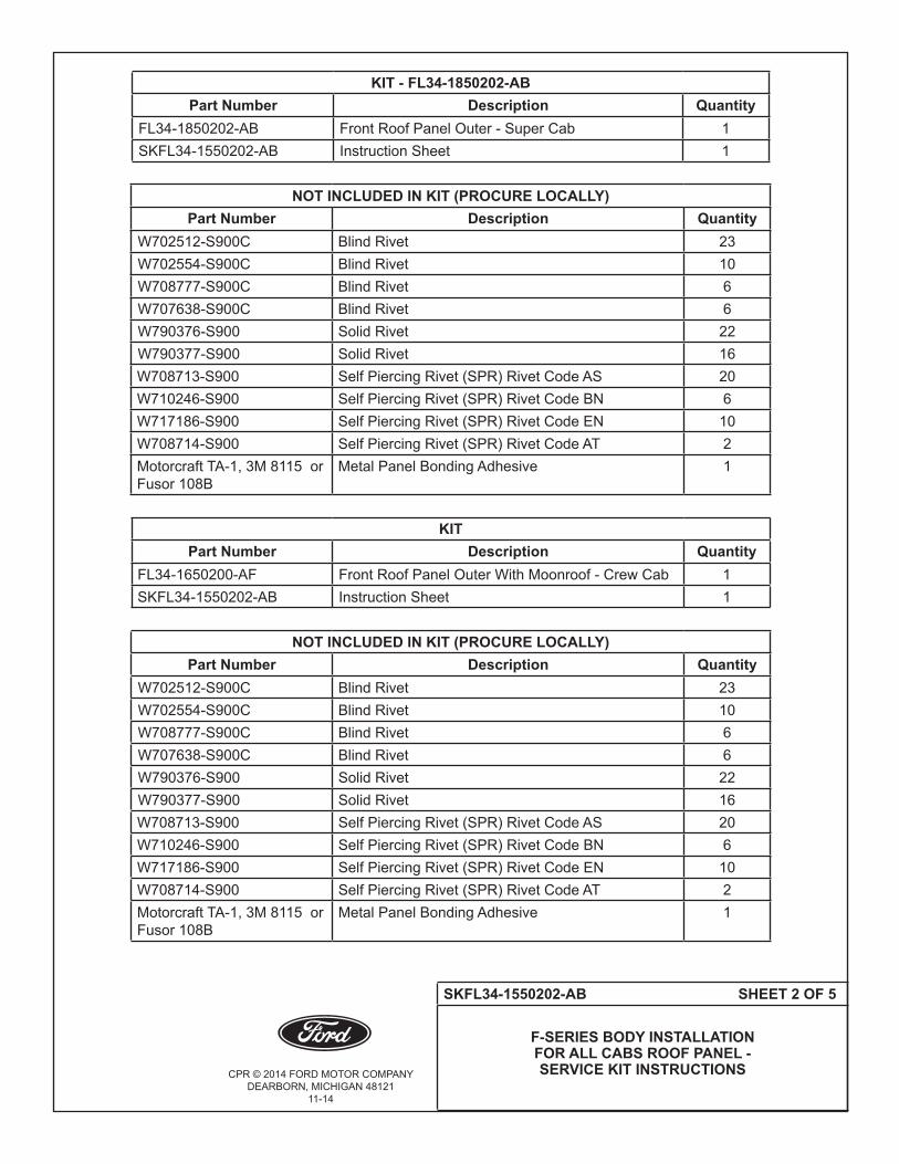
CPR © 2014 FORD MOTOR COMPANYDEARBORN, MICHIGAN 48121
11-14
SKFL34-1550202-AB SHEET 2 OF 5
F-SERIES BODY INSTALLATION FOR ALL CABS ROOF PANEL - SERVICE KIT INSTRUCTIONS
KIT - FL34-1850202-ABPart Number Description Quantity
FL34-1850202-AB Front Roof Panel Outer - Super Cab 1SKFL34-1550202-AB Instruction Sheet 1
NOT INCLUDED IN KIT (PROCURE LOCALLY)Part Number Description Quantity
W702512-S900C Blind Rivet 23W702554-S900C Blind Rivet 10W708777-S900C Blind Rivet 6W707638-S900C Blind Rivet 6W790376-S900 Solid Rivet 22W790377-S900 Solid Rivet 16W708713-S900 Self Piercing Rivet (SPR) Rivet Code AS 20W710246-S900 Self Piercing Rivet (SPR) Rivet Code BN 6W717186-S900 Self Piercing Rivet (SPR) Rivet Code EN 10W708714-S900 Self Piercing Rivet (SPR) Rivet Code AT 2Motorcraft TA-1, 3M 8115 or Fusor 108B
Metal Panel Bonding Adhesive 1
KIT Part Number Description Quantity
FL34-1650200-AF Front Roof Panel Outer With Moonroof - Crew Cab 1SKFL34-1550202-AB Instruction Sheet 1
NOT INCLUDED IN KIT (PROCURE LOCALLY)Part Number Description Quantity
W702512-S900C Blind Rivet 23W702554-S900C Blind Rivet 10W708777-S900C Blind Rivet 6W707638-S900C Blind Rivet 6W790376-S900 Solid Rivet 22W790377-S900 Solid Rivet 16W708713-S900 Self Piercing Rivet (SPR) Rivet Code AS 20W710246-S900 Self Piercing Rivet (SPR) Rivet Code BN 6W717186-S900 Self Piercing Rivet (SPR) Rivet Code EN 10W708714-S900 Self Piercing Rivet (SPR) Rivet Code AT 2Motorcraft TA-1, 3M 8115 or Fusor 108B
Metal Panel Bonding Adhesive 1

CPR © 2014 FORD MOTOR COMPANYDEARBORN, MICHIGAN 48121
11-14
SKFL34-1550202-AB SHEET 3 OF 5
F-SERIES BODY INSTALLATION FOR ALL CABS ROOF PANEL - SERVICE KIT INSTRUCTIONS
KIT Part Number Description Quantity
FL34-1850200-AF Front Roof Panel Outer With Moonroof - Super Cab 1SKFL34-1550202-AB Instruction Sheet 1
NOT INCLUDED IN KIT (PROCURE LOCALLY)Part Number Description Quantity
W702512-S900C Blind Rivet 23W702554-S900C Blind Rivet 10W708777-S900C Blind Rivet 6W707638-S900C Blind Rivet 6W790376-S900 Solid Rivet 22W790377-S900 Solid Rivet 16W708713-S900 Self Piercing Rivet (SPR) Rivet Code AS 20W710246-S900 Self Piercing Rivet (SPR) Rivet Code BN 6W717186-S900 Self Piercing Rivet (SPR) Rivet Code EN 10W708714-S900 Self Piercing Rivet (SPR) Rivet Code AT 2Motorcraft TA-1, 3M 8115 or Fusor 108B
Metal Panel Bonding Adhesive 1
SERVICE GUIDELINES:
• Aluminumrepairsshouldbeperformedinanareaprotectedfromsteelworkingareas,andtoolsusedin aluminumrepairshouldbequarantinedfromsteelrepairtools. • ReplacementSelf-PiercingRivets(SPRs)arethepreferredreplacementduringrepairfororiginalSPR locations,wherefeasible.BlindrivetsarethenextpreferredreplacementfororiginalSPRs.Insomecases,solid rivetsmayalsobeusedasareplacementforSPRs.Thefigureswillexplicitlycalloutwhichrivetsarepossible. • ReplacementSPRsaretobeinstalledadjacenttooriginalSPRlocation.
NOTE: Do not install replacement SPR in original SPR hole.
• BlindrivetsmaybeinstalledinoriginalSPRholes,aftertheyarereamedoutto6.5mm.Besuretogrindall surfacesoftheflangesmoothpriortoblindrivetinstallationinoriginalSPRlocations.
• FlowDrillScrews(FDS)aretobereplacedbyblindrivetsonly.TheoriginallocationoftheFDSisused,but reamedoutto6.5mm.
• Rivetsmayberemovedbydrilling,grinding,orSPRgunsetupasarivetremovaltool.
• Usingheat(notexceeding425°F)toloosenarivetbondedpanelshouldonlybedonewhenallpanelsinthe jointwillbereplacedorseparatedandnewadhesiveapplied.
• Flangepreparationforadhesiveistogrindtocleanmetalwith80-120grit,clean,andthenapplytheadhesive, spreadingitoutwithanacidbrush,coveringanyexposedaluminum.
• Clecosareanexcellentwaytoholdthepanelsintopositionwhenfittinganddrillingrivetholes.

CPR © 2014 FORD MOTOR COMPANYDEARBORN, MICHIGAN 48121
11-14
SKFL34-1550202-AB SHEET 4 OF 5
F-SERIES BODY INSTALLATION FOR ALL CABS ROOF PANEL - SERVICE KIT INSTRUCTIONS
FIGURE 1 RIVET LOCATIONS
• (RefertoFigure1)forlocationforadhesivematerial.
NOTE: The location of SPR and adhesive shown below are based on the original production drawings and should only be used as a guideline. NOTE: Apply adhesive along roof rail edges and sides for all cabs.
FIGURE 1
BLACK WAVY LINES REPRESENT THE LOCATION OF THE ADHESIVE MATERIAL
SQUARED NUMBERS ARE PRO SPOT MANDRELS1 SA-0400/SA-04012 SA-0400/SA-0402
CIRCLED NUMBERS ARE SOLID RIVETS1 W790376-S9002 W790377-S900
2ONE (1)W710246-S900BN DP10-200/HOR W708777-S900C BLIND RIVETS
FIVE (5)W717186-S900EN DG11-220/HOR W702554-S900C BLIND RIVETS
1 1
TEN (10)W708713-S900AS DZ09-025/HOR W702512-S900C BLIND RIVETS
2 2 2
1 11 1
FIVE (5)W717186-S900EN DG11-220/HOR W702554-S900C BLIND RIVETS
ONE (1)W710246-S900BN DP10-200/HOR W708777-S900C BLIND RIVETS

CPR © 2014 FORD MOTOR COMPANYDEARBORN, MICHIGAN 48121
11-14
SKFL34-1550202-AB SHEET 5 OF 5
F-SERIES BODY INSTALLATION FOR ALL CABS ROOF PANEL - SERVICE KIT INSTRUCTIONS
FIGURE 2 RIVET LOCATIONS
•(RefertoFigure2)forlocationforadhesivematerial. NOTE: The location of SPR and adhesive shown below are based on the original production drawings and should only be used as a guideline
FIGURE 2
TWO (2)W710246-S900BN DP10-200/HOR W708777-S900C BLIND RIVETS
TEN (10)W708713-S900AS DZ09-025/HOR W702512-S900C BLIND RIVETS
SQUARED NUMBERS ARE PRO SPOT MANDRELS1 SA-0400/SA-04012 SA-0400/SA-0402
CIRCLED NUMBERS ARE SOLID RIVETS1 W790376-S9002 W790377-S900
1 1
ONE (1)W708714-S900 AT DZ09-025/H OR W707638-S900C BLIND RIVETS
1 11 1
TWO (2)W710246-S900BN DP10-200/HOR W708777-S900C BLIND RIVETS1 1
ONE (1)W708714-S900 AT DZ09-025/H OR W707638-S900C BLIND RIVETS
1 1
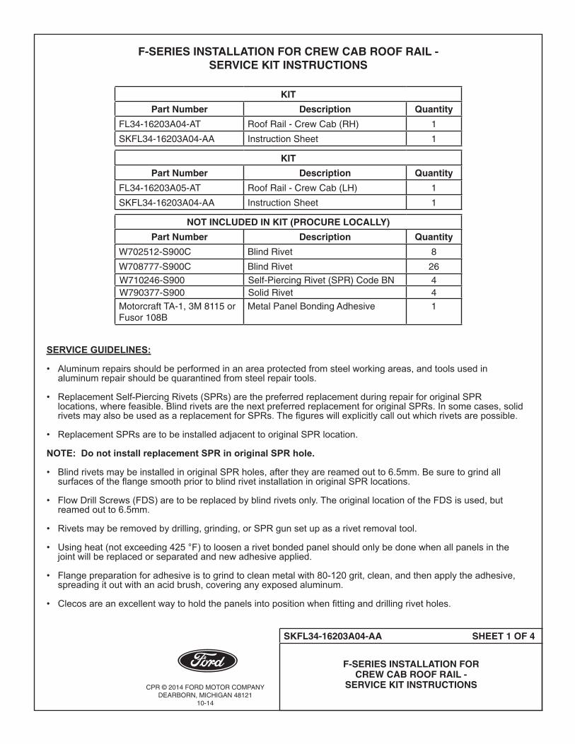
CPR © 2014 FORD MOTOR COMPANYDEARBORN, MICHIGAN 48121
10-14
SKFL34-16203A04-AA SHEET 1 OF 4
F-SERIES INSTALLATION FOR CREW CAB ROOF RAIL -
SERVICE KIT INSTRUCTIONS
F-SERIES INSTALLATION FOR CREW CAB ROOF RAIL - SERVICE KIT INSTRUCTIONS
KIT
Part Number Description Quantity
FL34-16203A04-AT Roof Rail - Crew Cab (RH) 1
SKFL34-16203A04-AA Instruction Sheet 1
KIT
Part Number Description Quantity
FL34-16203A05-AT Roof Rail - Crew Cab (LH) 1
SKFL34-16203A04-AA Instruction Sheet 1
NOT INCLUDED IN KIT (PROCURE LOCALLY)
Part Number Description Quantity
W702512-S900C Blind Rivet 8
W708777-S900C Blind Rivet 26
W710246-S900 Self-Piercing Rivet (SPR) Code BN 4W790377-S900 Solid Rivet 4
Motorcraft TA-1, 3M 8115 or Fusor 108B
Metal Panel Bonding Adhesive 1
SERVICE GUIDELINES:
• Aluminumrepairsshouldbeperformedinanareaprotectedfromsteelworkingareas,andtoolsusedin aluminumrepairshouldbequarantinedfromsteelrepairtools. • ReplacementSelf-PiercingRivets(SPRs)arethepreferredreplacementduringrepairfororiginalSPR locations,wherefeasible.BlindrivetsarethenextpreferredreplacementfororiginalSPRs.Insomecases,solid rivetsmayalsobeusedasareplacementforSPRs.Thefigureswillexplicitlycalloutwhichrivetsarepossible. • ReplacementSPRsaretobeinstalledadjacenttooriginalSPRlocation.
NOTE: Do not install replacement SPR in original SPR hole.
• BlindrivetsmaybeinstalledinoriginalSPRholes,aftertheyarereamedoutto6.5mm.Besuretogrindall surfacesoftheflangesmoothpriortoblindrivetinstallationinoriginalSPRlocations.
• FlowDrillScrews(FDS)aretobereplacedbyblindrivetsonly.TheoriginallocationoftheFDSisused,but reamedoutto6.5mm.
• Rivetsmayberemovedbydrilling,grinding,orSPRgunsetupasarivetremovaltool.
• Usingheat(notexceeding425°F)toloosenarivetbondedpanelshouldonlybedonewhenallpanelsinthe jointwillbereplacedorseparatedandnewadhesiveapplied.
• Flangepreparationforadhesiveistogrindtocleanmetalwith80-120grit,clean,andthenapplytheadhesive, spreadingitoutwithanacidbrush,coveringanyexposedaluminum.
• Clecosareanexcellentwaytoholdthepanelsintopositionwhenfittinganddrillingrivetholes.
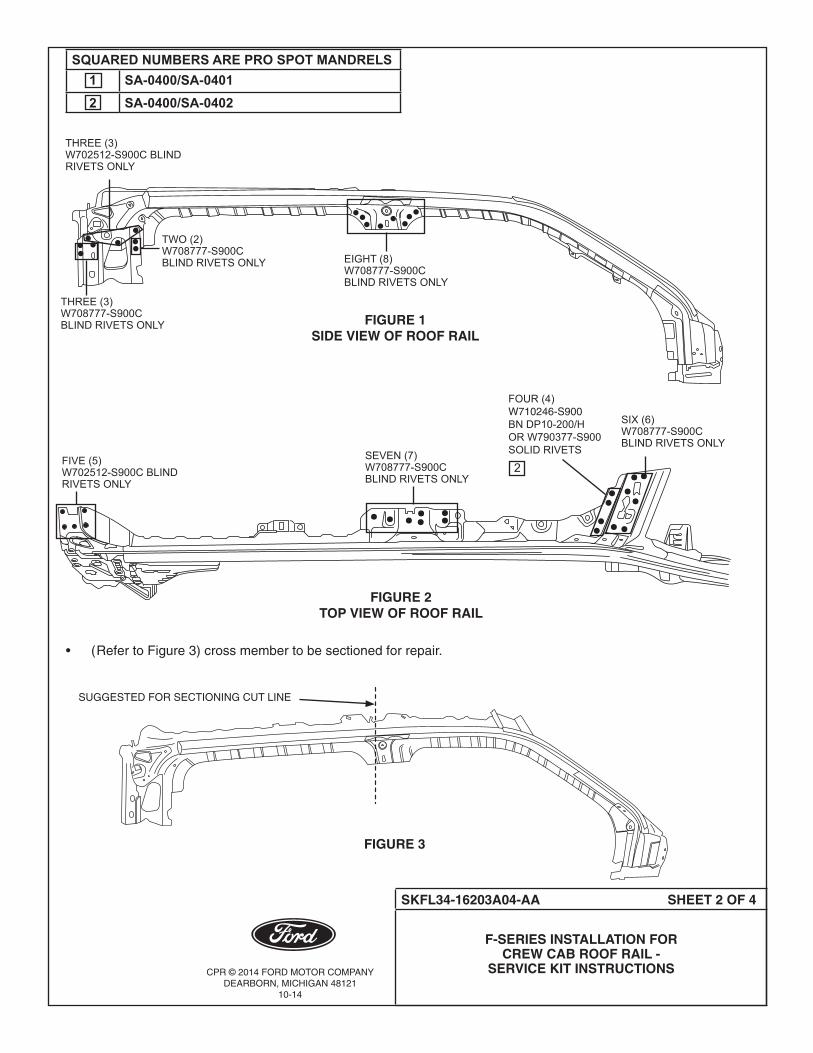
CPR © 2014 FORD MOTOR COMPANYDEARBORN, MICHIGAN 48121
10-14
SKFL34-16203A04-AA SHEET 2 OF 4
F-SERIES INSTALLATION FOR CREW CAB ROOF RAIL -
SERVICE KIT INSTRUCTIONS
• (RefertoFigure3)crossmembertobesectionedforrepair.
FIGURE 1SIDE VIEW OF ROOF RAIL
SUGGESTED FOR SECTIONING CUT LINE
FIGURE 3
FOUR(4)W710246-S900 BNDP10-200/HORW790377-S900SOLIDRIVETS
FIVE(5)W702512-S900CBLINDRIVETSONLY
SEVEN(7)W708777-S900CBLINDRIVETSONLY
SIX(6)W708777-S900CBLINDRIVETSONLY
EIGHT(8)W708777-S900CBLINDRIVETSONLY
THREE(3)W702512-S900CBLINDRIVETSONLY
TWO(2)W708777-S900C BLINDRIVETSONLY
THREE(3)W708777-S900CBLINDRIVETSONLY
FIGURE 2TOP VIEW OF ROOF RAIL
2
SQUARED NUMBERS ARE PRO SPOT MANDRELS1 SA-0400/SA-04012 SA-0400/SA-0402

CPR © 2014 FORD MOTOR COMPANYDEARBORN, MICHIGAN 48121
10-14
SKFL34-16203A04-AA SHEET 3 OF 4
F-SERIES INSTALLATION FOR CREW CAB ROOF RAIL -
SERVICE KIT INSTRUCTIONS
• Makecutsintubetoremovedamagedareas,thenmakea4”longinsert/backerforrepair.Donot damagetheB-pillarmountingbracketplate.(RefertoFigure4).
• Insert/backermaybeweldedintosectionusingfour(4)plugweldsthensolidweldtubefullyanddresswelds. (RefertoFigure5).
• (RefertoFigure6)forlocationforadhesivematerial.
NOTE: The location of SPR and adhesive shown below are based on the original production drawings and should only be used as a guideline.
BLACK WAVY LINES REPRESENT THE LOCATION OF THE ADHESIVE MATERIAL
FIGURE 6
FIGURE 5
BLACK WAVY LINES REPRESENT WELD
SEE VIEW A
VIEW A
FIGURE 4
BACKER/INSERT
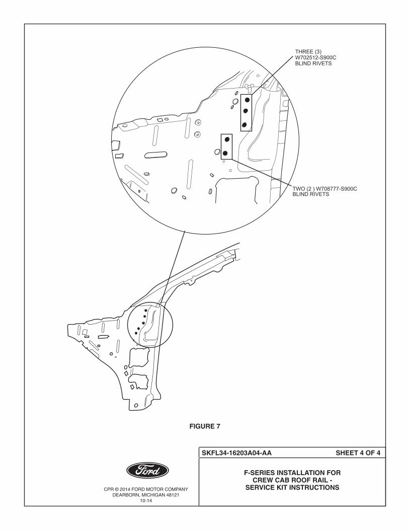
CPR © 2014 FORD MOTOR COMPANYDEARBORN, MICHIGAN 48121
10-14
SKFL34-16203A04-AA SHEET 4 OF 4
F-SERIES INSTALLATION FOR CREW CAB ROOF RAIL -
SERVICE KIT INSTRUCTIONS
FIGURE 7
TWO(2)W708777-S900CBLINDRIVETS
THREE(3)W702512-S900CBLINDRIVETS