I BODY BL A - PDF.TEXTFILES.COMpdf.textfiles.com/manuals/AUTOMOBILE/NISSAN/Altima/2002/bl.pdf ·...
182
BL-1 BODY, LOCK & SECURITY SYSTEM I BODY CONTENTS C D E F G H J K L M SECTION BL A B BL PRECAUTIONS ......................................................... 4 Precautions for Supplemental Restraint System (SRS) “AIR BAG” and “SEAT BELT PRE-TEN- SIONER” ................................................................. 4 Precautions for work ............................................... 4 Wiring Diagnosis and Trouble Diagnosis ................ 4 PREPARATION .......................................................... 5 Special service tool ................................................. 5 Commercial Service Tool ........................................ 5 SQUEAK AND RATTLE TROUBLE DIAGNOSIS ..... 6 Work Flow ............................................................... 6 CUSTOMER INTERVIEW .................................... 6 DUPLICATE THE NOISE AND TEST DRIVE ...... 7 CHECK RELATED SERVICE BULLETINS .......... 7 LOCATE THE NOISE AND IDENTIFY THE ROOT CAUSE ..................................................... 7 REPAIR THE CAUSE .......................................... 7 CONFIRM THE REPAIR ...................................... 8 Generic Squeak and Rattle Troubleshooting .......... 8 INSTRUMENT PANEL ......................................... 8 CENTER CONSOLE ............................................ 8 DOORS ................................................................ 8 TRUNK ................................................................. 9 SUNROOF/HEADLINER ...................................... 9 SEATS .................................................................. 9 UNDERHOOD ...................................................... 9 Diagnostic Worksheet ........................................... 10 HOOD ...................................................................... 12 Fitting Adjustment ................................................. 12 FRONT END HEIGHT ADJUSTMENT AND LAT- ERAL/LONGITUDINAL CLEARANCE ADJUST- MENT. ................................................................ 12 SURFACE HEIGHT ADJUSTMENT .................. 12 Removal and Installation of Hood Assembly ......... 13 Removal and Installation of Hood Lock Control .... 14 REMOVAL .......................................................... 14 INSTALLATION .................................................. 14 Hood Lock Control Inspection ............................... 15 POWER DOOR LOCK SYSTEM ............................. 16 Component Parts and Harness Connector Location ... 16 System Description ................................................ 17 OUTLINE ............................................................ 17 OPERATIONS BY MAIN POWER WINDOW AND DOOR LOCK/UNLOCK SWITCH ....................... 18 KEY–TRAP PREVENTIVE FUNCTION ............. 18 Schematic .............................................................. 19 Wiring Diagram -D/LOCK- ..................................... 20 FIG. 1 .................................................................. 20 FIG. 2 .................................................................. 21 FIG. 3 .................................................................. 22 FIG. 4 .................................................................. 23 Terminals and Reference Value for BCM .............. 24 Work Flow .............................................................. 24 Preliminary Check ................................................. 25 FUSE CHECK .................................................... 25 CONSULT–II Function ........................................... 25 CONSULT–II BASIC OPERATION PROCE- DURE ................................................................. 25 DATA MONITOR ................................................ 26 ACTIVE TEST .................................................... 26 Symptom Chart ...................................................... 27 Door Switch Check ................................................ 28 Key Switch (Insert) Check ..................................... 29 Door Lock/Unlock Switch Check (With left front only power window anti–pinch system) ......................... 30 Door Lock/Unlock Switch Check (With left and right front power window anti–pinch system) ................. 33 Door Lock Actuator Check (Front LH) ................... 36 Door Lock Actuator Check (Front RH and rear LH/ RH) ........................................................................ 37 Front Door Key Cylinder Switch LH Check (With left front only power window anti-pinch system) .......... 38 Door Lock/Unlock Switch Check (With left and right front power window anti–pinch system) ................. 39 Front Door Key Cylinder Switch LH Check (With left and right front power window anti–pinch system)... 41 REMOTE KEYLESS ENTRY SYSTEM .................... 43 Component Parts and Harness Connector Location ... 43 System Description ................................................ 44 INPUTS .............................................................. 44
Transcript of I BODY BL A - PDF.TEXTFILES.COMpdf.textfiles.com/manuals/AUTOMOBILE/NISSAN/Altima/2002/bl.pdf ·...

BL-1
BODY, LOCK & SECURITY SYSTEM
I BODY
CONTENTS
C
D
E
F
G
H
J
K
L
M
SECTION BLA
B
BL
PRECAUTIONS .......................................................... 4Precautions for Supplemental Restraint System (SRS) “AIR BAG” and “SEAT BELT PRE-TEN-SIONER” .................................................................. 4Precautions for work ................................................ 4Wiring Diagnosis and Trouble Diagnosis ................. 4
PREPARATION ........................................................... 5Special service tool .................................................. 5Commercial Service Tool ......................................... 5
SQUEAK AND RATTLE TROUBLE DIAGNOSIS ...... 6Work Flow ................................................................ 6
CUSTOMER INTERVIEW ..................................... 6DUPLICATE THE NOISE AND TEST DRIVE ....... 7CHECK RELATED SERVICE BULLETINS ........... 7LOCATE THE NOISE AND IDENTIFY THE ROOT CAUSE ...................................................... 7REPAIR THE CAUSE ........................................... 7CONFIRM THE REPAIR ....................................... 8
Generic Squeak and Rattle Troubleshooting ........... 8INSTRUMENT PANEL .......................................... 8CENTER CONSOLE ............................................. 8DOORS ................................................................. 8TRUNK .................................................................. 9SUNROOF/HEADLINER ....................................... 9SEATS ................................................................... 9UNDERHOOD ....................................................... 9
Diagnostic Worksheet ............................................ 10HOOD ....................................................................... 12
Fitting Adjustment .................................................. 12FRONT END HEIGHT ADJUSTMENT AND LAT-ERAL/LONGITUDINAL CLEARANCE ADJUST-MENT. ................................................................. 12SURFACE HEIGHT ADJUSTMENT ................... 12
Removal and Installation of Hood Assembly .......... 13Removal and Installation of Hood Lock Control ..... 14
REMOVAL ........................................................... 14INSTALLATION ................................................... 14
Hood Lock Control Inspection ................................ 15POWER DOOR LOCK SYSTEM .............................. 16
Component Parts and Harness Connector Location ... 16
System Description ................................................. 17OUTLINE ............................................................. 17OPERATIONS BY MAIN POWER WINDOW AND DOOR LOCK/UNLOCK SWITCH ........................ 18KEY–TRAP PREVENTIVE FUNCTION .............. 18
Schematic ............................................................... 19Wiring Diagram -D/LOCK- ...................................... 20
FIG. 1 ................................................................... 20FIG. 2 ................................................................... 21FIG. 3 ................................................................... 22FIG. 4 ................................................................... 23
Terminals and Reference Value for BCM ............... 24Work Flow ............................................................... 24Preliminary Check .................................................. 25
FUSE CHECK ..................................................... 25CONSULT–II Function ............................................ 25
CONSULT–II BASIC OPERATION PROCE-DURE .................................................................. 25DATA MONITOR ................................................. 26ACTIVE TEST ..................................................... 26
Symptom Chart ....................................................... 27Door Switch Check ................................................. 28Key Switch (Insert) Check ...................................... 29Door Lock/Unlock Switch Check (With left front only power window anti–pinch system) .......................... 30Door Lock/Unlock Switch Check (With left and right front power window anti–pinch system) .................. 33Door Lock Actuator Check (Front LH) .................... 36Door Lock Actuator Check (Front RH and rear LH/RH) ......................................................................... 37Front Door Key Cylinder Switch LH Check (With left front only power window anti-pinch system) ........... 38Door Lock/Unlock Switch Check (With left and right front power window anti–pinch system) .................. 39Front Door Key Cylinder Switch LH Check (With left and right front power window anti–pinch system) ... 41
REMOTE KEYLESS ENTRY SYSTEM ..................... 43Component Parts and Harness Connector Location ... 43System Description ................................................. 44
INPUTS ............................................................... 44

BL-2
OPERATED PROCEDURE ................................. 44CAN Communication System Description .............. 45
FOR TCS MODELS ............................................. 46FOR A/T MODELS .............................................. 47FOR M/T MODELS .............................................. 48
Schematic ............................................................... 50Wiring Diagram — KEYLES— ................................ 51
FIG. 1 ................................................................... 51FIG. 2 ................................................................... 52FIG. 3 ................................................................... 53FIG. 4 ................................................................... 54
Terminals and Reference Value for BCM ................ 55CONSULT-II Function ............................................. 55CONSULT-II Inspection Procedure ......................... 56
“MULTI REMOTE ENT” ....................................... 56CONSULT-II Application Items ............................... 57
“MULTI REMOTE CONT SYS” ............................ 57Trouble Diagnosis Procedure ................................. 58Pre-Diagnosis Inspection ........................................ 59
BCM POWER SUPPLY AND GROUND CIRCUIT INSPECTION ....................................................... 59
Trouble Diagnoses .................................................. 59SYMPTOM CHART ............................................. 59
Key Fob Battery and Function Check ..................... 61Door Switch Check ................................................. 62Key Switch (insert) Check ...................................... 63Trunk Release Solenoid Check .............................. 64Hazard Reminder Check ........................................ 65Horn Reminder Check ............................................ 67Interior Lamp Operation Check .............................. 68Ignition Illumination Operation Check ..................... 69Step Lamp Operation Check .................................. 70ID Code Entry Procedure ....................................... 71
KEY FOB ID SET UP WITH CONSULT-II ........... 71KEY FOB ID SET UP WITHOUT CONSULT-II .... 73
Key Fob Battery Replacement ................................ 74DOOR ........................................................................ 75
Fitting Adjustment ................................................... 75FRONT DOOR .................................................... 75REAR DOOR ....................................................... 75STRIKER ADJUSTMENT .................................... 75
Removal and Installation ........................................ 76Door Weatherstrip ................................................... 77
FRONT DOOR LOCK ............................................... 78Component Structure .............................................. 78Inspection and Adjustment. .................................... 78
EXTERIOR HANDLE ROD ADJUSTMENT ........ 78Removal and Installation ........................................ 78
REMOVAL ........................................................... 78Disassembly and Assembly .................................... 79
DISASSEMBLY ................................................... 79ASSEMBLY ......................................................... 79
REAR DOOR LOCK .................................................. 80Components ........................................................... 80Inspection and Adjustment ..................................... 80
EXTERIOR HANDLE ROD ADJUSTMENT ........ 80Removal and Installation of Door Lock ................... 80
REMOVAL ...........................................................80Disassembly and Assembly ....................................81
DISASSEMBLY ....................................................81ASSEMBLY ..........................................................81
TRUNK LID ................................................................82Fitting Adjustment ...................................................82
LONGITUDINAL AND LATERAL CLEARANCE ADJUSTMENT .....................................................82SURFACE HEIGHT ADJUSTMENT ....................82
Removal and Installation of Trunk Lid Assembly ....83Removal and Installation of Trunk Lid Lock ............83
LOCK REMOVAL .................................................83STRIKER REMOVAL ...........................................83LOCK AND STRIKER INSTALLATION ...............83
Removal and Installation of Trunk Lid Weatherstrip ...84TRUNK LID OPENER ...............................................85
Wiring Diagram -TLID- ............................................85Terminals and Reference Value for BCM ................86
VEHICLE SECURITY (THEFT WARNING) SYSTEM ...87Component Parts and Harness Connector Location ...87System Description .................................................89
DESCRIPTION ....................................................89POWER SUPPLY ................................................89INITIAL CONDITION TO ACTIVATE THE SYS-TEM .....................................................................89VEHICLE SECURITY SYSTEM ALARM OPER-ATION ..................................................................90VEHICLE SECURITY SYSTEM DEACTIVATION ...90PANIC ALARM OPERATION ...............................90
CAN Communication System Description ..............90FOR TCS MODELS .............................................91FOR A/T MODELS ...............................................92FOR M/T MODELS ..............................................93
Schematic ...............................................................95Wiring Diagram -VEHSEC- .....................................96
FIG. 1 ...................................................................96FIG. 2 ...................................................................97FIG. 3 ...................................................................98FIG. 4 ...................................................................99FIG. 5 .................................................................100
CONSULT-II Function ...........................................101CONSULT-II INSPECTION PROCEDURE ........101CONSULT-II APPLICATION ITEM .....................101
Trouble Diagnosis .................................................103WORK FLOW ....................................................103
Preliminary Check .................................................104Symptom Chart .....................................................105Diagnostic Procedure 1 .........................................106Diagnostic Procedure 2 .........................................109Diagnostic Procedure 3 ......................................... 110Diagnostic Procedure 4 ......................................... 112Diagnostic Procedure 5 ......................................... 113Diagnostic Procedure 6 ......................................... 114Diagnostic Procedure 7 ......................................... 115
NVIS(NISSAN VEHICLE IMMOBILIZER SYSTEM-NATS) ......................................................................116
Component Parts and Harness Connector Location . 116System Description ............................................... 117System Composition ............................................. 117

BL-3
C
D
E
F
G
H
J
K
L
M
A
B
BL
Wiring Diagram — NATS — ..................................118CONSULT-II ..........................................................119
CONSULT-II INSPECTION PROCEDURE ........119CONSULT-II DIAGNOSTIC TEST MODE FUNC-TION .................................................................. 120HOW TO READ SELF-DIAGNOSTIC RESULTS . 120NVIS (NATS) SELF-DIAGNOSTIC RESULTS ITEM CHART .................................................... 121
Trouble Diagnoses ............................................... 122WORK FLOW .................................................... 122SYMPTOM MATRIX CHART 1 (SELF-DIAGNO-SIS RELATED ITEM) ........................................ 123SYMPTOM MATRIX CHART 2 (NON SELF-DIAGNOSIS RELATED ITEM) .......................... 123DIAGNOSTIC SYSTEM DIAGRAM .................. 124DIAGNOSTIC PROCEDURE 1 ......................... 124DIAGNOSTIC PROCEDURE 2 ......................... 125DIAGNOSTIC PROCEDURE 3 ......................... 128DIAGNOSTIC PROCEDURE 4 ......................... 129DIAGNOSTIC PROCEDURE 5 ......................... 130DIAGNOSTIC PROCEDURE 6 ......................... 131DIAGNOSTIC PROCEDURE 7 ......................... 133
How to Replace NVIS (NATS) IMMU ................... 134INTEGRATED HOMELINK TRANSMITTER .......... 135
Wiring Diagram —TRNSCV— ............................. 135Trouble Diagnoses ............................................... 136
DIAGNOSTIC PROCEDURE ............................ 136BODY REPAIR ........................................................ 138
Body Exterior Paint Color ..................................... 138Body Component Parts ........................................ 139
UNDERBODY COMPONENT PARTS .............. 139BODY COMPONENT PARTS ........................... 141
Corrosion Protection ............................................ 143DESCRIPTION .................................................. 143
ANTI-CORROSIVE WAX .................................. 144UNDERCOATING .............................................. 145
Body Sealing ........................................................ 146DESCRIPTION .................................................. 146
Body Construction ................................................ 149BODY CONSTRUCTION .................................. 149
Body Alignment .................................................... 150BODY CENTER MARKS ................................... 150PANEL PARTS MATCHING MARKS ................. 151DESCRIPTION .................................................. 152ENGINE COMPARTMENT ................................ 153UNDERBODY ................................................... 155PASSENGER COMPARTMENT ....................... 157REAR BODY ..................................................... 159
Handling Precautions for Plastics ......................... 161HANDLING PRECAUTIONS FOR PLASTICS .. 161LOCATION OF PLASTIC PARTS ...................... 162
Precautions in Repairing High Strength Steel ....... 164HIGH STRENGTH STEEL (HSS) USED IN NIS-SAN VEHICLES ................................................ 164
Replacement Operations ...................................... 167DESCRIPTION .................................................. 167HOODLEDGE ................................................... 170HOODLEDGE (PARTIAL REPLACEMENT) ..... 171FRONT SIDE MEMBER .................................... 172FRONT SIDE MEMBER (PARTIAL REPLACE-MENT) ............................................................... 173FRONT PILLAR ................................................. 174CENTER PILLAR .............................................. 177OUTER SILL ..................................................... 178REAR FENDER ................................................. 179REAR PANEL .................................................... 180REAR FLOOR REAR ........................................ 181REAR SIDE MEMBER EXTENSION ................. 182

BL-4
PRECAUTIONS
PRECAUTIONS PFP:00001
Precautions for Supplemental Restraint System (SRS) “AIR BAG” and “SEAT BELT PRE-TENSIONER” EIS000PD
The Supplemental Restraint System such as “AIR BAG” and “SEAT BELT PRE-TENSIONER”, used alongwith a front seat belt, helps to reduce the risk or severity of injury to the driver and front passenger for certaintypes of collision. Information necessary to service the system safely is included in the SRS and SB section ofthis Service Manual.WARNING:● To avoid rendering the SRS inoperative, which could increase the risk of personal injury or death
in the event of a collision which would result in air bag inflation, all maintenance must be per-formed by an authorized NISSAN/INFINITI dealer.
● Improper maintenance, including incorrect removal and installation of the SRS, can lead to per-sonal injury caused by unintentional activation of the system. For removal of Spiral Cable and AirBag Module, see the SRS section.
● Do not use electrical test equipment on any circuit related to the SRS unless instructed to in thisService Manual. SRS wiring harnesses can be identified by yellow and/or orange harness connec-tors.
Precautions for work EIS000PE
● After removing and installing the opening/closing parts, be sure to carry out fitting adjustments to checktheir operation.
● Check the lubrication level, damage, and wear of each part. If necessary, grease or replace it.
Wiring Diagnosis and Trouble Diagnosis EIS000PF
When you read wiring diagrams, refer to the following:● GI-12, "How to Read Wiring Diagrams"● PG-3, "POWER SUPPLY ROUTING CIRCUIT"When you perform trouble diagnosis, refer to the following: ● GI-10, "HOW TO FOLLOW TEST GROUPS IN TROUBLE DIAGNOSES"● GI-25, "How to Perform Efficient Diagnosis for an Electrical Incident"
Check for any Service bulletins before servicing the vehicle.

PREPARATION
BL-5
C
D
E
F
G
H
J
K
L
M
A
B
BL
PREPARATION PFP:00002
Special service tool EIS000PG
The actual shapes of Kent-Moore tools may differ from those of special service tools illustrated here.
Commercial Service Tool EIS000PH
Tool number(Kent-Moore No.)Tool name
Description
(J-39570)Chassis ear
Locating the noise
(J-43980)NISSAN Squeak and Rat-tle Kit
Repairing the cause of noise
(J-43241)Remote Keyless Entry Tester
Used to test key fobs
SIIA0993E
SIIA0994E
LEL946A
Tool name Description
Engine ear Locating the noise
SIIA0995E

BL-6
SQUEAK AND RATTLE TROUBLE DIAGNOSIS
SQUEAK AND RATTLE TROUBLE DIAGNOSIS PFP:00000
Work Flow EIS000PI
CUSTOMER INTERVIEWInterview the customer if possible, to determine the conditions that exist when the noise occurs. Use the Diag-nostic Worksheet during the interview to document the facts and conditions when the noise occurs and anycustomer's comments; refer BL-10, "Diagnostic Worksheet" . This information is necessary to duplicate theconditions that exist when the noise occurs.● The customer may not be able to provide a detailed description or the location of the noise. Attempt to
obtain all the facts and conditions that exist when the noise occurs (or does not occur).● If there is more than one noise in the vehicle, be sure to diagnose and repair the noise that the customer
is concerned about. This can be accomplished by test driving the vehicle with the customer. ● After identifying the type of noise, isolate the noise in terms of its characteristics.The noise characteristics
are provided so the customer, service adviser and technician are all speaking the same language whendefining the noise.
● Squeak —(Like tennis shoes on a clean floor)Squeak characteristics include the light contact/fast movement/brought on by road conditions/hard sur-faces=higher pitch noise/softer surfaces=lower pitch noises/edge to surface=chirping
● Creak—(Like walking on an old wooden floor)Creak characteristics include firm contact/slow movement/twisting with a rotational movement/pitchdependent on materials/often brought on by activity.
● Rattle—(Like shaking a baby rattle)Rattle characteristics include the fast repeated contact/vibration or similar movement/loose parts/missingclip or fastener/incorrect clearance.
● Knock —(Like a knock on a door)Knock characteristics include hollow sounding/sometimes repeating/often brought on by driver action.
● Tick—(Like a clock second hand)Tick characteristics include gentle contacting of light materials/loose components/can be caused by driveraction or road conditions.
● Thump—(Heavy, muffled knock noise)Thump characteristics include softer knock/dead sound often drought on by activity.
● Buzz—(Like a bumble bee)Buzz characteristics include high frequency rattle/firm contact.
● Often the degree of acceptable noise level will vary depending upon the person. A noise that you mayjudge as acceptable may be very irritating to the customer.
● Weather conditions, especially humidity and temperature, may have a great effect on noise level.
SBT842

SQUEAK AND RATTLE TROUBLE DIAGNOSIS
BL-7
C
D
E
F
G
H
J
K
L
M
A
B
BL
DUPLICATE THE NOISE AND TEST DRIVEIf possible, drive the vehicle with the customer until the noise is duplicated. Note any additional information onthe Diagnostic Worksheet regarding the conditions or location of the noise. This information can be used toduplicate the same conditions when you confirm the repair.If the noise can be duplicated easily during the test drive, to help identify the source of the noise, try to dupli-cate the noise with the vehicle stopped by doing one or all of the following:1) Close a door.2) Tap or push/pull around the area where the noise appears to be coming from.3) Rev the engine.4) Use a floor jack to recreate vehicle "twist".5) At idle, apply engine load (electrical load, half-clutch on M/T model, drive position on A/T model).6) Raise the vehicle on a hoist and hit a tire with a rubber hammer.● Drive the vehicle and attempt to duplicate the conditions the customer states exist when the noise occurs.● If it is difficult to duplicate the noise, drive the vehicle slowly on an undulating or rough road to stress the
vehicle body.
CHECK RELATED SERVICE BULLETINSAfter verifying the customer concern or symptom, check ASIST for Technical Service Bulletins (TSBs) relatedto that concern or symptom.If a TSB relates to the symptom, follow the procedure to repair the noise.
LOCATE THE NOISE AND IDENTIFY THE ROOT CAUSE1. Narrow down the noise to a general area. To help pinpoint the source of the noise, use a listening tool
(Chassis Ear: J-39570, Engine Ear and mechanic's stethoscope).2. Narrow down the noise to a more specific area and identify the cause of the noise by:● removing the components in the area that you suspect the noise is coming from.
Do not use too much force when removing clips and fasteners, otherwise clips and fastener can be bro-ken or lost during the repair, resulting in the creation of new noise.
● tapping or pushing/pulling the component that you suspect is causing the noise.Do not tap or push/pull the component with excessive force, otherwise the noise will be eliminated onlytemporarily.
● feeling for a vibration with your hand by touching the component(s) that you suspect is (are) causing thenoise.
● placing a piece of paper between components that you suspect are causing the noise.● looking for loose components and contact marks.
Refer to BL-8, "Generic Squeak and Rattle Troubleshooting" .
REPAIR THE CAUSE ● If the cause is a loose component, tighten the component securely.● If the cause is insufficient clearance between components:– separate components by repositioning or loosening and retightening the component, if possible.– insulate components with a suitable insulator such as urethane pads, foam blocks, felt cloth tape or ure-
thane tape. A Nissan Squeak and Rattle Kit (J-43980) is available through your authorized Nissan PartsDepartment.
CAUTION:Do not use excessive force as many components are constructed of plastic and may be damaged.Always check with the Parts Department for the latest parts information.The following materials are contained in the Nissan Squeak and Rattle Kit (J-43980). Each item can beordered separately as needed.URETHANE PADS [1.5 mm (0.059 in) thick]Insulates connectors, harness, etc.76268-9E005: 100×135 mm (3.94×5.31 in)/76884-71L01: 60×85 mm (2.36×3.35 in)/76884-71L02: 15×25mm (0.59×0.98 in)INSULATOR (Foam blocks)Insulates components from contact. Can be used to fill space behind a panel.73982-9E000: 45 mm (1.77 in) thick, 50×50 mm (1.97×1.97 in)/73982-50Y00: 10 mm (0.39 in) thick,50×50 mm (1.97×1.97 in)INSULATOR (Light foam block)
BL-8
SQUEAK AND RATTLE TROUBLE DIAGNOSIS
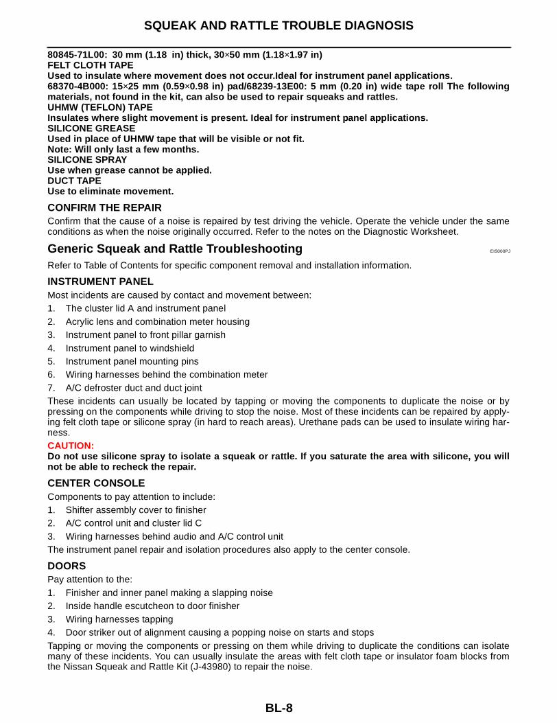
80845-71L00: 30 mm (1.18 in) thick, 30×50 mm (1.18×1.97 in)FELT CLOTH TAPEUsed to insulate where movement does not occur.Ideal for instrument panel applications.68370-4B000: 15×25 mm (0.59×0.98 in) pad/68239-13E00: 5 mm (0.20 in) wide tape roll The followingmaterials, not found in the kit, can also be used to repair squeaks and rattles.UHMW (TEFLON) TAPE Insulates where slight movement is present. Ideal for instrument panel applications.SILICONE GREASEUsed in place of UHMW tape that will be visible or not fit.Note: Will only last a few months.SILICONE SPRAYUse when grease cannot be applied.DUCT TAPEUse to eliminate movement.
CONFIRM THE REPAIRConfirm that the cause of a noise is repaired by test driving the vehicle. Operate the vehicle under the sameconditions as when the noise originally occurred. Refer to the notes on the Diagnostic Worksheet.
Generic Squeak and Rattle Troubleshooting EIS000PJ
Refer to Table of Contents for specific component removal and installation information.
INSTRUMENT PANELMost incidents are caused by contact and movement between:1. The cluster lid A and instrument panel2. Acrylic lens and combination meter housing3. Instrument panel to front pillar garnish4. Instrument panel to windshield5. Instrument panel mounting pins6. Wiring harnesses behind the combination meter 7. A/C defroster duct and duct jointThese incidents can usually be located by tapping or moving the components to duplicate the noise or bypressing on the components while driving to stop the noise. Most of these incidents can be repaired by apply-ing felt cloth tape or silicone spray (in hard to reach areas). Urethane pads can be used to insulate wiring har-ness.CAUTION:Do not use silicone spray to isolate a squeak or rattle. If you saturate the area with silicone, you willnot be able to recheck the repair.
CENTER CONSOLEComponents to pay attention to include:1. Shifter assembly cover to finisher2. A/C control unit and cluster lid C3. Wiring harnesses behind audio and A/C control unitThe instrument panel repair and isolation procedures also apply to the center console.
DOORSPay attention to the:1. Finisher and inner panel making a slapping noise2. Inside handle escutcheon to door finisher3. Wiring harnesses tapping 4. Door striker out of alignment causing a popping noise on starts and stopsTapping or moving the components or pressing on them while driving to duplicate the conditions can isolatemany of these incidents. You can usually insulate the areas with felt cloth tape or insulator foam blocks fromthe Nissan Squeak and Rattle Kit (J-43980) to repair the noise.
SQUEAK AND RATTLE TROUBLE DIAGNOSIS
BL-9
C
D
E
F
G
H
J
K
L
M
A
B
BL
TRUNKTrunk noises are often caused by a loose jack or loose items put into the trunk by the owner.In addition look for:1. Trunk lid bumpers out of adjustment2. Trunk lid striker out of adjustment 3. The trunk lid torsion bars knocking together4. A loose license plate or bracketMost of these incidents can be repaired by adjusting, securing or insulating the item(s) or component(s) caus-ing the noise.
SUNROOF/HEADLINERNoises in the sunroof/headliner area can often be traced to one of the following:1. Sunroof lid, rail, linkage or seals making a rattle or light knocking noise2. Sun visor shaft shaking in the holder3. Front or rear windshield touching headliner and squeaking Again, pressing on the components to stop the noise while duplicating the conditions can isolate most of theseincidents. Repairs usually consist of insulating with felt cloth tape.
SEATSWhen isolating seat noise it's important to note the position the seat is in and the load placed on the seat whenthe noise is present. These conditions should be duplicated when verifying and isolating the cause of thenoise.Cause of seat noise include: 1. Headrest rods and holder 2. A squeak between the seat pad cushion and frame 3. The rear seatback lock and bracket These noises can be isolated by moving or pressing on the suspected components while duplicating the con-ditions under which the noise occurs. Most of these incidents can be repaired by repositioning the componentor applying urethane tape to the contact area.
UNDERHOODSome interior noise may be caused by components under the hood or on the engine wall. The noise is thentransmitted into the passenger compartment.Causes of transmitted underhood noise include:1. Any component mounted to the engine wall2. Components that pass through the engine wall3. Engine wall mounts and connectors4. Loose radiator mounting pins5. Hood bumpers out of adjustment 6. Hood striker out of adjustmentThese noise can be difficult to isolate since they cannot be reached from the interior of the vehicle. The bestmethod is to secure, move or insulate one component at a time and test drive the vehicle. Also, engine RPMor load can be changed to isolate the noise. Repairs can usually be made by moving, adjusting, securing, orinsulating the component causing the noise.

BL-10
SQUEAK AND RATTLE TROUBLE DIAGNOSIS
Diagnostic Worksheet EIS000PK
ABT468

SQUEAK AND RATTLE TROUBLE DIAGNOSIS
BL-11
C
D
E
F
G
H
J
K
L
M
A
B
BL
SBT844
BL-12
HOOD
HOOD PFP:F5100
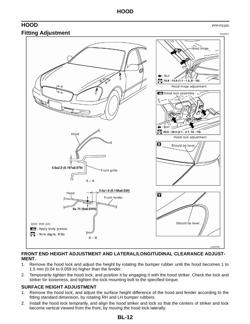
Fitting Adjustment EIS000PL
FRONT END HEIGHT ADJUSTMENT AND LATERAL/LONGITUDINAL CLEARANCE ADJUST-MENT.1. Remove the hood lock and adjust the height by rotating the bumper rubber until the hood becomes 1 to
1.5 mm (0.04 to 0.059 in) higher than the fender.2. Temporarily tighten the hood lock, and position it by engaging it with the hood striker. Check the lock and
striker for looseness, and tighten the lock mounting bolt to the specified torque.
SURFACE HEIGHT ADJUSTMENT1. Remove the hood lock, and adjust the surface height difference of the hood and fender according to the
fitting standard dimension, by rotating RH and LH bumper rubbers.2. Install the hood lock temprarily, and align the hood striker and lock so that the centers of striker and lock
become vertical viewed from the front, by moving the hood lock laterally.
LIIA0204E

HOOD
BL-13
C
D
E
F
G
H
J
K
L
M
A
B
BL
3. Check that the secondary latch is properly engaged with thesecondary striker with hood's own weight by dropping it fromapprox. 200 mm (7.87 in) height or by pressing it lightly approx.3 kg (29 N).CAUTION:Do not drop the hood from 300 mm (11.81 in) height orhigher.
4. Move the hood lock up and down so that the striker and lock areengaged firmly with the hood closed.
5. Tighten the lock mounting bolts to the specified torque.
Removal and Installation of Hood Assembly EIS000PM
1. Remove the hinge mounting nuts on the hood to remove the hood assembly.Install in the reverse order of removal.
PIIA0181E
LIIA0108E

BL-14
HOOD
Removal and Installation of Hood Lock Control EIS000PN
REMOVAL1. Disconnect the hood lock cable from the hood lock, and clip it
from the radiator core upper support and hood ledge.2. Remove the mounting screws, and remove the hood opener.3. Remove the grommet on the instrument panel, and pull the hood
lock cable toward the passenger compartment.CAUTION:While pulling, be careful not to damage (peeling) the out-side of the hood lock cable.
INSTALLATION1. Pull the hood lock cable through the panel hole to the engine compartment.
Be careful not to bend the cable too much, keeping the radius100 mm (3.94 in) or more.
2. Check that the cable is not offset from the positioning grommet,and push the grommet into the panel hole securely.
3. Apply the sealant to the grommet (at * mark) properly.
LIIA0110E
SIIA0326E
PIIA0173E

HOOD
BL-15
C
D
E
F
G
H
J
K
L
M
A
B
BL
4. Install the cable securely to the lock.5. After installing, check the hood lock adjustment and hood
opener operation.
Hood Lock Control Inspection EIS000PO
CAUTION:If the hood lock cable is bent or deformed, replace it.1. Check that the secondary latch is properly engaged with the
secondary striker with hood's own weight by dropping it fromapprox. 200 mm (7.87 in) height.
2. While operating the hood opener, carefully check that the frontend of the hood is raised by approx. 20 mm (0.79 in). Also checkthat the hood opener returns to the original position.
3. Check the hood lock lubrication condition. If necessary, apply"body grease" to the points shown in the figure.
PIIA0174E
PIIA0175E
PIIA0176E
BL-16
POWER DOOR LOCK SYSTEM
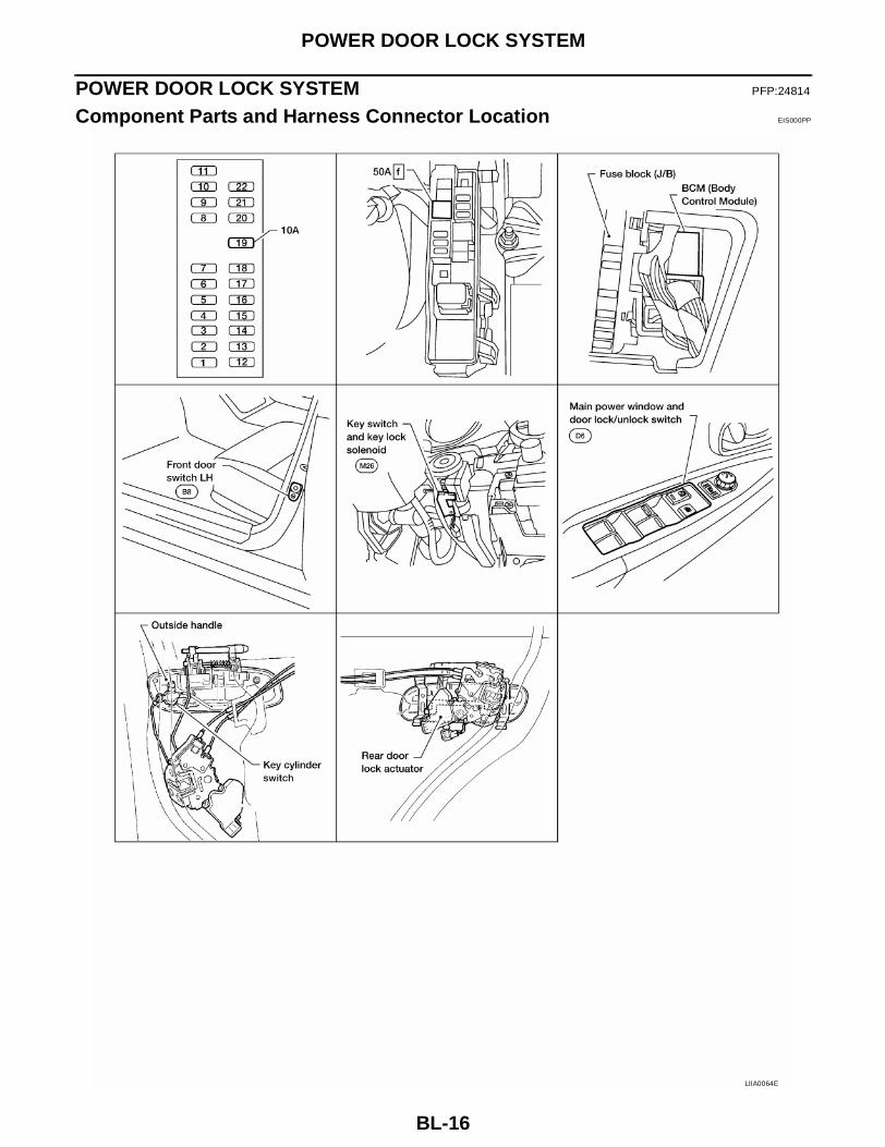
POWER DOOR LOCK SYSTEM PFP:24814
Component Parts and Harness Connector Location EIS000PP
LIIA0064E

POWER DOOR LOCK SYSTEM
BL-17
C
D
E
F
G
H
J
K
L
M
A
B
BL
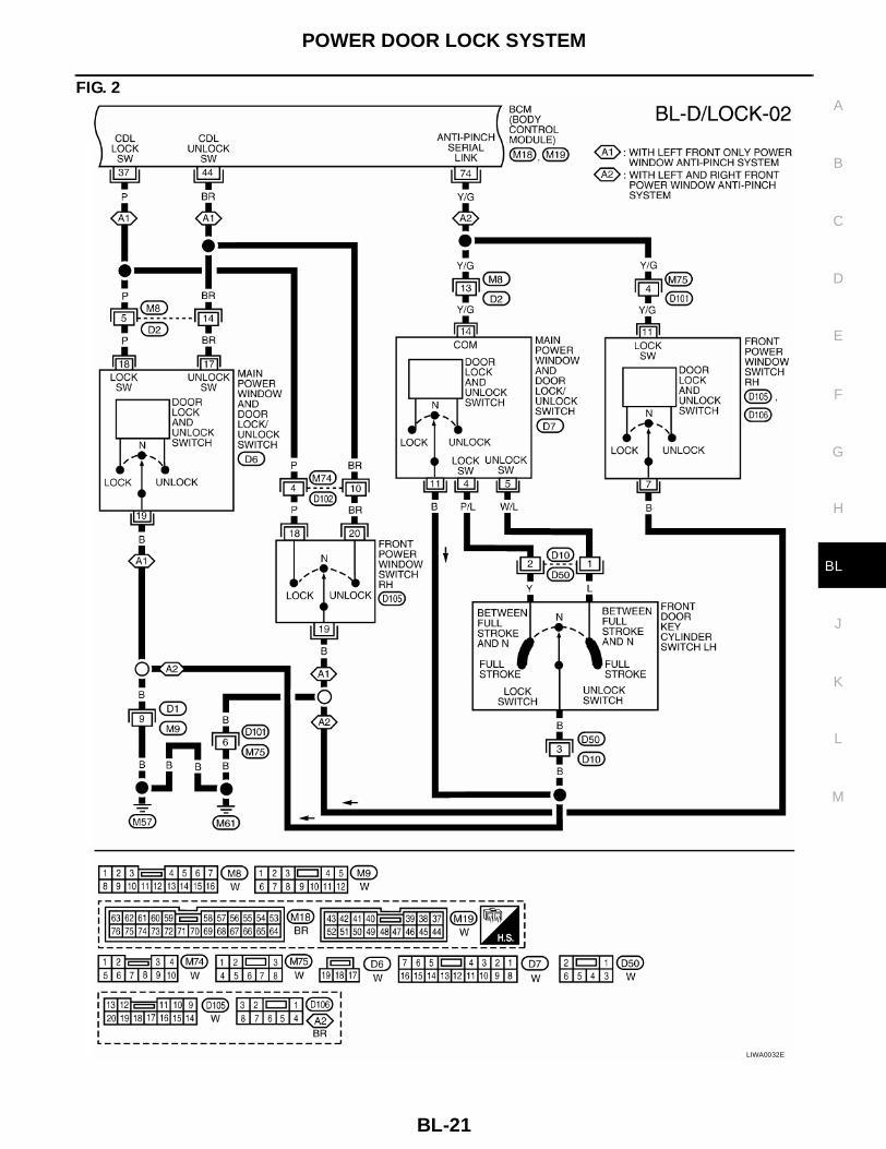
System Description EIS000PQ
Power is supplied at all time● to BCM terminal 7● through 50A fusible link (letter f, located in the fuse and fusible link box)● through 10A fuse [No.19, located in the fuse block (J/B)]● to key switch and keylock solenoid terminal 3.With ignition key inserted, power is supplied● through key switch and keylock solenoid terminal 4● to BCM terminal 62.Ground is supplied to terminal 8 of BCM through body grounds E15 and E24 and to terminals 27 and 63 ofBCM through body ground M57 and M61.When the door is locked with main power window and door lock/unlock switch, ground is supplied● through terminal 19 of main power window and door lock/unlock switch through body grounds M57 and
M61 ● to BCM terminal 37 and● through main power window and door lock/unlock switch terminal 18. (with left front only power window
anti–pinch system)When the door is unlocked with main power window and door lock/unlock switch, ground is supplied● through terminal 19 of main power window and door lock/unlock switch through body grounds M57 and
M61● to BCM terminal 44● through main power window and door lock/unlock switch terminal 17 (with left front only power window
anti–pinch system).When the door is locked with front power window switch RH, ground is suppied● through terminal 19 front power window switch RH through body grounds M57 and M61● to BCM terminal 37● through front power window switch RH terminal 18 (with left front only power window anti–pinch system).When the door is unlocked with front power window switch RH, ground is supplied● through terminal 19 of front power window switch RH through body grounds M57 and M61● to BCM terminal 44● through front power window switch RH terminal 20 (with left front only power window anti–pinch system).When the door is locked with front door key cylinder switch LH, ground is suppied● to body grounds M57 and M61● through BCM terminal 59 (with left front only power window anti–pinch system).When the door is unlocked with front door key cylinder switch LH, ground is supplied● to body grounds M57 and M61● through BCM terminal 60 (with left front only power window anti–pinch system).BCM is connected to main power window and door lock/unlock switch and front power window switch RH asanti–pinch serial link (with left and right front power window anti–pinch system).Main power window and door lock/unlock switch and front power window switch RH output to key cylinderlock/unlock switch, central lock/unlock switch and power window UP/DOWN control by key cylinder switch asDATALINE (anti–pinch serial link) to BCM.
OUTLINEFunctions available by operating the central switches on driver's door and passenger's door● Interlocked with the locking operation of central switch, door lock actuators of all doors are locked.● Interlocked with the unlocking operation of central switch, door lock actuators of all doors are unlocked.
Functions available by operating the key cylinder switch on driver's door● Interlocked with the locking operation of door key cylinder, door lock actuators of all doors are locked.● When door key cylinder is unlocked, fron door lock actuator LH is unlocked.

BL-18
POWER DOOR LOCK SYSTEM
● When door key cylinder is unlocked for the second time within 5 seconds after the first operation, doorlock actuators on all doors are unlocked.
Key–trap preventive functionWhen central switch is operated to lock doors with ignition key put in key cylinder and any door open, all doorlock actuators are locked and then unlocked.
OPERATIONS BY MAIN POWER WINDOW AND DOOR LOCK/UNLOCK SWITCHTime chart
KEY–TRAP PREVENTIVE FUNCTIONTime chart
SIIA1328E
LIIA0165E

POWER DOOR LOCK SYSTEM
BL-19
C
D
E
F
G
H
J
K
L
M
A
B
BL
Schematic EIS000PR
LIWA0030E

BL-20
POWER DOOR LOCK SYSTEM
Wiring Diagram -D/LOCK- EIS000PS
FIG. 1
LIWA0031E
POWER DOOR LOCK SYSTEM
BL-21
C
D
E
F
G
H
J
K
L
M
A
B
BL
FIG. 2
LIWA0032E

BL-22
POWER DOOR LOCK SYSTEM
FIG. 3
LIWA0033E

POWER DOOR LOCK SYSTEM
BL-23
C
D
E
F
G
H
J
K
L
M
A
B
BL
FIG. 4
LIWA0034E

BL-24
POWER DOOR LOCK SYSTEM
Terminals and Reference Value for BCM EIS000PT
*:Without vehicle security system.
Work Flow EIS000PU
1. Check the symptom and customer's requests.2. Understand the outline of system. Refer to BL-17, "System Description" .3. Perform the preliminary check. Refer to BL-25, "Preliminary Check" .4. According to the trouble diagnosis chart, repair or replace the cause of the malfunction.Refer to BL-27,
"Symptom Chart" .5. Does rear window defogger operate normally? OK: GO TO 6, NG: GO TO 4.6. INSPECTION END.
TERMI-NAL
WIRE COLOR
ITEM CONDITION VOLTAGE
7 W/B BAT power supply — Battery voltage
8 B Ground — —
10 P/L Front door switch RH Door open (ON) → Door close (OFF) 0V → Battery voltage
11 R/B Rear door switch LH/RH Door open (ON) → Door close (OFF) 0V → Battery voltage
14 SB Front door switch LH Door open (ON) → Door close (OFF) OV → Battery voltage
23 G/WFront door lock actuator LH (unlock)
Driver door lock knob (locked → un locked)
0V → Battery voltage
27 B Ground — —
30 Y/R All door lock actuator (lock) Driver door lock knob (neutral → lock) 0V → Battery voltage
31 G/RFront door lock actuator RH and Rear door lock actuators LH/RH (unlock)
Door lock and unlock switch (locked → unlocked)
0V → Battery voltage
37 P Lock switch signalDoor lock and unlock switch (unlocked
→ locked)Battery voltage → 0V
44 BR Unlock switch signalDoor lock and unlock switch (locked →
unlocked)Battery voltage → 0V
54* SB Option switch Door open (ON) → Door close (OFF) 0V → Battery voltage
59 P/LFront door key cylinder switch LH (lock)
OFF (neutral) → ON (locked) 5V → 0V
60 W/LFront door key cylinder switch LH (unlock)
OFF (neutral) → ON (unlocked) 5V → 0V
62 B/R Key switch (insert)Key inserted (ON) → Key removed from
IGN key cylinder (OFF)Battery voltage → 0V
63 B Ground — —
74 Y/G Anti–pinch serial link —
LIIA0166E

POWER DOOR LOCK SYSTEM
BL-25
C
D
E
F
G
H
J
K
L
M
A
B
BL
Preliminary Check EIS000PV
FUSE CHECK
1. FUSE INSPECTION
● Check the following BCM fuse and fusible link.
NOTE:Refer to BL-16, "Component Parts and Harness Connector Location" .
OK or NG ?OK >> Inspection End .NG >> If fuse is blown, be sure to eliminate cause of problem before installing new fuse, refer to PG-3,
"POWER SUPPLY ROUTING CIRCUIT" .
CONSULT–II Function EIS000PW
Power door lock system check with data monitor and active test can be executed by combining data receptionand command transmission via communication line from BCM.
CONSULT–II BASIC OPERATION PROCEDURE1. With ignition switch OFF, connect CONSULT–II to data link con-
nector on vehicle, and turn ON ignition switch.2. Touch “START”.
3. Touch “BCM” on “SELECT SYSTEM” screen.
COMPONENT PARTS TERMINAL NO. (SIGNAL) AMPERE NO. LOCATION
BCM 62 (BAT power supply) 10A 19 Fuse block (J/B)
BCM 7 (BAT power supply) 50A f Fuse and fusible link box
BCM diagnosis part
Inspection item, self–diagnosis mode
Content
Door lockData monitor Displays BCM input data on real–time basis.
Active test Sends drive signals to door lock actuator to perform operation check.
BBIA0002E
LIIA0033E
BL-26
POWER DOOR LOCK SYSTEM
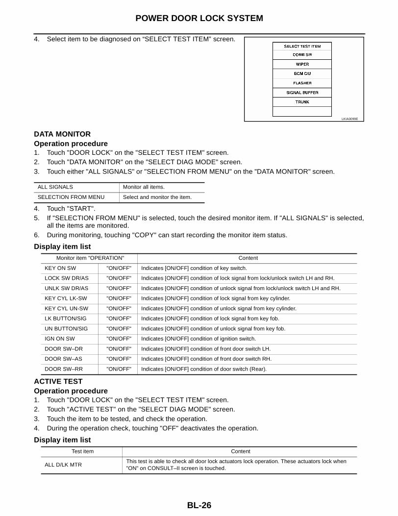
4. Select item to be diagnosed on “SELECT TEST ITEM” screen.
DATA MONITOROperation procedure1. Touch "DOOR LOCK" on the "SELECT TEST ITEM" screen.2. Touch "DATA MONITOR" on the "SELECT DIAG MODE" screen.3. Touch either "ALL SIGNALS" or "SELECTION FROM MENU" on the "DATA MONITOR" screen.
4. Touch "START".5. If "SELECTION FROM MENU" is selected, touch the desired monitor item. If "ALL SIGNALS" is selected,
all the items are monitored.6. During monitoring, touching "COPY" can start recording the monitor item status.
Display item list
ACTIVE TESTOperation procedure1. Touch "DOOR LOCK" on the "SELECT TEST ITEM" screen.2. Touch "ACTIVE TEST" on the "SELECT DIAG MODE" screen.3. Touch the item to be tested, and check the operation.4. During the operation check, touching "OFF" deactivates the operation.
Display item list
LKIA0099E
ALL SIGNALS Monitor all items.
SELECTION FROM MENU Select and monitor the item.
Monitor item "OPERATION" Content
KEY ON SW "ON/OFF" Indicates [ON/OFF] condition of key switch.
LOCK SW DR/AS "ON/OFF" Indicates [ON/OFF] condition of lock signal from lock/unlock switch LH and RH.
UNLK SW DR/AS "ON/OFF" Indicates [ON/OFF] condition of unlock signal from lock/unlock switch LH and RH.
KEY CYL LK-SW "ON/OFF" Indicates [ON/OFF] condition of lock signal from key cylinder.
KEY CYL UN-SW "ON/OFF" Indicates [ON/OFF] condition of unlock signal from key cylinder.
LK BUTTON/SIG "ON/OFF" Indicates [ON/OFF] condition of lock signal from key fob.
UN BUTTON/SIG "ON/OFF" Indicates [ON/OFF] condition of unlock signal from key fob.
IGN ON SW "ON/OFF" Indicates [ON/OFF] condition of ignition switch.
DOOR SW–DR "ON/OFF" Indicates [ON/OFF] condition of front door switch LH.
DOOR SW–AS "ON/OFF" Indicates [ON/OFF] condition of front door switch RH.
DOOR SW–RR "ON/OFF" Indicates [ON/OFF] condition of door switch (Rear).
Test item Content
ALL D/LK MTRThis test is able to check all door lock actuators lock operation. These actuators lock when "ON" on CONSULT–II screen is touched.

POWER DOOR LOCK SYSTEM
BL-27
C
D
E
F
G
H
J
K
L
M
A
B
BL
Symptom Chart EIS000PX
DR D/UN MTRThis test is able to check front door lock actuator LH unlock operation.These actuators lock when "ON" on CONSULT–II screen is touched.
NON DR D/UNThis test is able to check door lock actuators (except front door lock actuator LH) unlock oper-ation.These actuators unlock when "ON" on CONSULT–II screen is touched.
Test item Content
Symptom Malfunctioning system Power window system
Key reminder door system does not operate properly.
Door switch check. Refer to BL-28, "Door Switch Check" .
—Key switch (Insert) check. Refer to BL-29, "Key Switch (Insert) Check" .
If above systems are "OK", replace BCM.
Power door lock does not operate with door lock and unlock switch on main power window and door lock/unlock switch or front power window switch RH
Door lock and unlock switch check. Refer to BL-30, "Door Lock/Unlock Switch Check (With left front only power window anti–pinch system)" .
With left front only anti–pinch system.
Door lock and unlock switch check. Refer to BL-33, "Door Lock/Unlock Switch Check (With left and right front power window anti–pinch system)" .
With left and right front anti–pinch system.
Power door lock does not operate with driver door lock knob switch.
Door lock actuator check –Driver–. Refer to BL-36, "Door Lock Actuator Check (Front LH)" .
—
Specific door lock acutuator does not operate.Door lock actuator check (passenger, Rear LH/RH).Refer to BL-37, "Door Lock Actuator Check (Front RH and rear LH/RH)" .
—
Power door lock does not operate with front door key cylinder LH operation.
Front door key cylinder switch LH check. Refer to BL-38, "Front Door Key Cylinder Switch LH Check (With left front only power window anti-pinch system)" .
With left front only anti–pinch system.
Door lock and unlock switch check. Refer to BL-39, "Door Lock/Unlock Switch Check (With left and right front power window anti–pinch system)" . With left and right front
anti–pinch system.Front door key cylinder switch LH check. Refer to BL-41, "Front Door Key Cylinder Switch LH Check (With left and right front power window anti–pinch system)" .
If above system are "OK", replace BCM. —
BL-28
POWER DOOR LOCK SYSTEM
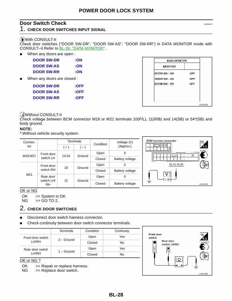
Door Switch Check EIS000PY
1. CHECK DOOR SWITCHES INPUT SIGNAL
With CONSULT-IICheck door switches ("DOOR SW-DR", "DOOR SW-AS", "DOOR SW-RR") in DATA MONITOR mode withCONSULT–II.Refer to BL-26, "DATA MONITOR" .● When any doors are open :
● When any doors are closed :
Without CONSULT-IICheck voltage between BCM connector M18 or M21 terminals 10(P/L), 11(R/B) and 14(SB) or 54*(SB) andbody ground.NOTE:*:Without vehicle security system.
OK or NGOK >> System is OK.NG >> GO TO 2.
2. CHECK DOOR SWITCHES
● Disconnect door switch harness connector.● Check continuity between door switch connector terminals.
OK or NG ?OK >> Repair or replace harness.NG >> Replace door switch.
DOOR SW-DR :ON
DOOR SW-AS :ON
DOOR SW-RR :ON
DOOR SW-DR :OFF
DOOR SW-AS :OFF
DOOR SW-RR :OFF
LIIA0035E
Connec-tor
TerminalsCondition
Voltage (V)(Approx.)( + ) ( – )
M18,M21Front door switch LH
14,54 GroundOpen 0
Closed Battery voltage
M21
Front door switch RH
10 GroundOpen 0
Closed Battery voltage
Rear door switch LH/
RH11 Ground
Open 0
Closed Battery voltage LIIA0167E
Terminals Condition Continuity
Front door switch LH/RH
2 – GroundOpen Yes
Closed No
Rear door switch LH/RH
1 – GroundOpen Yes
Closed No
LIIA0168E

POWER DOOR LOCK SYSTEM
BL-29
C
D
E
F
G
H
J
K
L
M
A
B
BL
Key Switch (Insert) Check EIS000PZ
1. CHECK KEY SWITCH INPUT SIGNAL
With CONSULT-IICheck key switch "KEY ON SW" in DATA MONITOR mode with CONSULT–II.Refer to BL-26, "DATA MONI-TOR" .● When key is inserted to ignition key cylinder :
● When key is removed from ignition key cylinder :
Without CONSULT-IICheck voltage between BCM connector M18 terminal 62(B/R) and ground.
OK or NG ?OK >> System is OK.NG >> GO TO 2.
2. CHECK KEY SWITCH (INSERT)
Check continuity between key switch connector terminals.
OK or NG ?OK >> Repair or replace harness.NG >> Replace key switch.
KEY ON SW :ON
KEY ON SW :OFF
LIIA0169E
Connec-tor
TerminalCondition Voltage (V)
( + ) ( – )
M18 62 GroundKey is inserted. Battery voltage
Key is removed. 0
LIIA0170E
Terminals Condition Continuity
3 – 4Key is inserted. Yes
Key is removed. No
LIIA0171E

BL-30
POWER DOOR LOCK SYSTEM
Door Lock/Unlock Switch Check (With left front only power window anti–pinch system) EIS000Q0
1. CHECK DOOR LOCK/UNLOCK SWITCH INPUT SIGNAL
With CONSULT-IICheck door lock/unlock switch ("LOCK SW DR/AS", "UNLK SW DR/AS") in DATA MONITOR mode in CON-SULT–II.Refer to BL-26, "DATA MONITOR"● When door lock/unlock switch is turned to LOCK :
● When door lock/unlock switch is turned to UNLOCK :
Without CONSULT-IICheck voltage between BCM connector M19 terminals 37(P) and 44(BR) and ground.
OK or NG ?OK >> System is OK.NG >> GO TO 2.
LOCK SW DR/AS :ON
UNLK SW DR/AS :ON
LIIA0172E
Connec-tor
TerminalCondition Voltage (V)
( + ) ( – )
M19
37 Ground
Door lock/unlock switch is neutral.
Battery voltage
Door lock/unlock switch is turned to LOCK.
0
44 Ground
Door lock/unlock switch is neutral.
Battery voltage
Door lock/unlock switch is turned to UNLOCK.
0 LIIA0173E

POWER DOOR LOCK SYSTEM
BL-31
C
D
E
F
G
H
J
K
L
M
A
B
BL
2. CHECK DOOR LOCK/UNLOCK SWITCH GROUND HARNESS
Check continuity between main power window and door lock/unlock switch connector D6 terminal 19(B) andfront power window switch RH connector D105 terminal 19(B) and body ground.● Main power window and door lock/unlock switch
● Front power window switch RH
OK or NG ?OK >> GO TO 3.NG >> Repair or replace harness.
Connector Terminals Continuity
D6 19 – Ground Yes
LIIA0174E
Connector Terminals Continuity
D105 19 – Ground Yes
LIIA0175E
BL-32
POWER DOOR LOCK SYSTEM
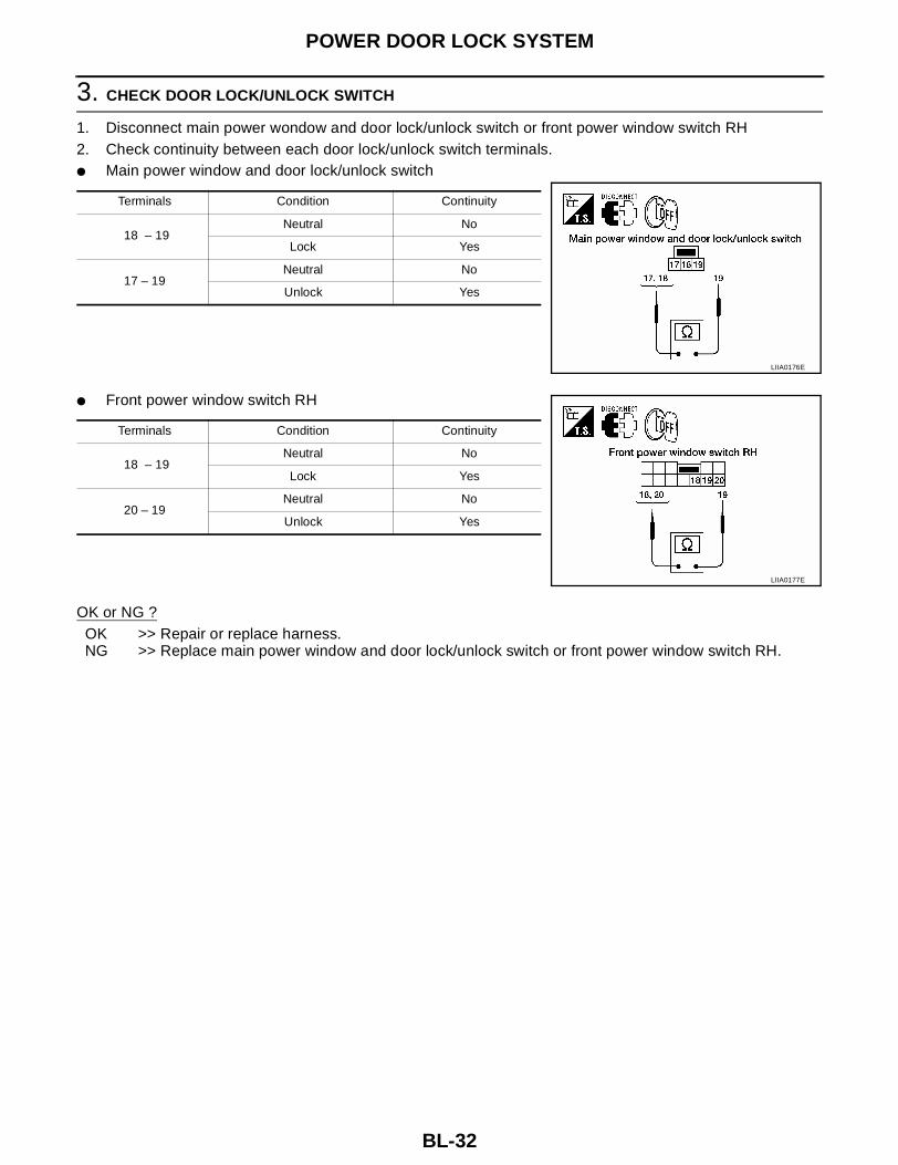
3. CHECK DOOR LOCK/UNLOCK SWITCH
1. Disconnect main power wondow and door lock/unlock switch or front power window switch RH2. Check continuity between each door lock/unlock switch terminals.● Main power window and door lock/unlock switch
● Front power window switch RH
OK or NG ?OK >> Repair or replace harness.NG >> Replace main power window and door lock/unlock switch or front power window switch RH.
Terminals Condition Continuity
18 – 19 Neutral No
Lock Yes
17 – 19 Neutral No
Unlock Yes
LIIA0176E
Terminals Condition Continuity
18 – 19 Neutral No
Lock Yes
20 – 19 Neutral No
Unlock Yes
LIIA0177E

POWER DOOR LOCK SYSTEM
BL-33
C
D
E
F
G
H
J
K
L
M
A
B
BL
Door Lock/Unlock Switch Check (With left and right front power window anti–pinch system) EIS000Q1
1. CHECK DOOR LOCK/UNLOCK SWITCH INPUT SIGNAL
With CONSULT-IICheck door lock/unlock switch ("LOCK SW DR/AS", "UNLK SW DR/AS") in DATA MONITOR mode in CON-SULT–II.Refer to BL-26, "DATA MONITOR" .● When door lock/unlock switch is turned to LOCK :
● When door lock/unlock switch is turned to UNLOCK :
Without CONSULT-IICheck voltage between BCM connector M18 terminal 74(Y/G) and ground.
OK or NG ?OK >> System is OK.NG >> GO TO 2.
LOCK SW DR/AS :ON
UNLK SW DR/AS :ON
LIIA0172E
Connec-tor
TerminalCondition Voltage (V)
( + ) ( – )
M18 74 Ground —
LIIA0178ELIIA0166E

BL-34
POWER DOOR LOCK SYSTEM
2. CHECK DOOR LOCK/UNLOCK SWITCH GROUND HARNESS
Check continuity between main power window and door lock/unlock switch connector D7 terminal 11(B) andfront power window switch RH connector D106 terminal 7(B) and body ground.● Main power window and door lock/unlock switch
● Front power window switch RH
OK or NG ?OK >> GO TO 3.NG >> Repair or replace harness.
Connector Terminals Continuity
D7 11 – Ground Yes
LIIA0179E
Connector Terminals Continuity
D106 7 – Ground Yes
LIIA0180E
POWER DOOR LOCK SYSTEM
BL-35
C
D
E
F
G
H
J
K
L
M
A
B
BL
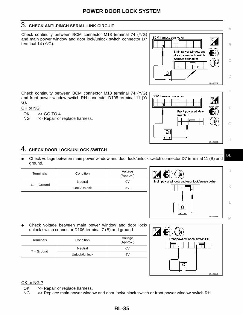
3. CHECK ANTI-PINCH SERIAL LINK CIRCUIT
Check continuity between BCM connector M18 terminal 74 (Y/G)and main power window and door lock/unlock switch connector D7terminal 14 (Y/G).
Check continuity between BCM connector M18 terminal 74 (Y/G)and front power window switch RH connector D105 terminal 11 (Y/G).OK or NGOK >> GO TO 4.NG >> Repair or replace harness.
4. CHECK DOOR LOCK/UNLOCK SWITCH
● Check voltage between main power window and door lock/unlock switch connector D7 terminal 11 (B) andground.
● Check voltage between main power window and door lock/unlock switch connector D106 terminal 7 (B) and ground.
OK or NG ?OK >> Repair or replace harness.NG >> Replace main power window and door lock/unlock switch or front power window switch RH.
LIIA0205E
LIIA0206E
Terminals ConditionVoltage
(Approx.)
11 – GroundNeutral 0V
Lock/Unlock 5V
LIIA0181E
Terminals ConditionVoltage
(Approx.)
7 – GroundNeutral 0V
Unlock/Unlock 5V
LIIA0182E

BL-36
POWER DOOR LOCK SYSTEM
Door Lock Actuator Check (Front LH) EIS000Q2
1. CHECK DOOR LOCK ACTUATOR SIGNAL
With CONSULT-IICheck front door lock actuator LH "ALL D/LK MTR", "DR D/UN MTR"in ACTIVE TEST mode with CONSULT–II. Refer to BL-26, "ACTIVETEST" .
Without CONSULT-IICheck voltage between BCM connector M20 terminals 23(G/W), 30(Y/R) and ground.
OK or NG ?OK >> System is OK.NG >> GO TO 2.
2. CHECK DOOR LOCK ACTUATOR HARNESS
Check continuity between BCM connector M20 terminals 23(G/W),30(Y/R) and front door lock actuator LH connector D51 terminals 1(R), 3(B) and body ground.
OK or NG ?OK >> Replace front door lock actuator LH.NG >> Repair or replace harness.
ALL D/LK MTR : ON/OFF
DR D/UN MTR : ON/OFF
WIIA0107E
Connec-tor
TerminalCondition Voltage (V)
( + ) ( – )
M20
23 GroundDriver door lock knob is turned to UNLOCK.
0 → Battery voltage
30 GroundDriver door lock knob is turned to LOCK.
0 → Battery voltage
LIIA0184E
Con-nector
TerminalCon-
nectorTerminal Continuity
M20
23D51
3 Should exist
30 1 Should exist
23, 30 Ground Should not exist
LIIA0185E

POWER DOOR LOCK SYSTEM
BL-37
C
D
E
F
G
H
J
K
L
M
A
B
BL
Door Lock Actuator Check (Front RH and rear LH/RH) EIS000Q3
1. CHECK DOOR LOCK ACTUATOR SIGNAL
With CONSULT-IICheck door lock actuators "ALL D/LK MTR", "NON DR D/UN" inACTIVE TEST mode with CONSULT–II. Refer to BL-26, "ACTIVETEST" .
Without CONSULT-IICheck voltage between BCM connector M20 terminals 30(Y/R), 31(G/R) and ground.
OK or NG ?OK >> System is OK.NG >> GO TO 2.
2. CHECK DOOR LOCK ACTUATOR HARNESS
Check continuity between BCM connector M20 terminals 30(Y/R),31(G/R) and front door lock actuator RH, rear door lock actuator LH/RH connector D151, D205 and D305 terminals 1(G/R), 3(Y/R) andbody ground.
OK or NG ?OK >> Replace front door lock actuator RH or rear door lock actuator LH/RH.NG >> Repair or replace harness.
ALL D/LK MTR : ON/OFF
NON DR D/UN : ON/OFF
WIIA0107E
Connec-tor
TerminalCondition Voltage (V)
( + ) ( – )
M20
30 GroundDriver door lock knob is turned to LOCK.
0 → Battery voltage
31 GroundDoor lock/unlock switch is turned to UNLOCK.
0 → Battery voltage
LIIA0186E
Connector Terminal Connector Terminal Continuity
M20
30 D151, D205, D305
3 Should exist
31 1 Should exist
30, 31 Ground Should not exist
LIIA0187E

BL-38
POWER DOOR LOCK SYSTEM
Front Door Key Cylinder Switch LH Check (With left front only power window anti-pinch system) EIS000Q4
1. CHECK DOOR KEY CYLINDER SWITCH LH SIGNAL
With CONSULT-IICheck front door key cylinder switch ("KEY CYL LK-SW", "KEY CYL UN-SW") in DATA MONITOR mode inCONSULT–II.Refer to BL-26, "DATA MONITOR" .● When key inserted in front key cylinder is turned to LOCK :
● When key inserted in front key cylinder is turned to UNLOCK :
Without CONSULT-IICheck voltage between BCM connector M18 terminals 59 (P/L), 60 (W/L) and ground.
OK or NG ?OK >> System is OK.NG >> GO TO 2.
2. CHECK FRONT DOOR KEY CYLINDER SWITCH LH GROUND HARNESS
Check continuity between front door key cylinder switch LH connector D50 terminal 3 (B) and body ground.
OK or NG ?OK >> GO TO 3.NG >> Repair or replace harness.
KEY CYL LK-SW : ON
KEY CYL UN-SW : ON
LIIA0188E
Connec-tor
TerminalCondition Voltage (V)
( + ) ( – )
M18
59 Ground
Front door key cylinder switch LH is neutral.
Approx.5
Front door key cylinder switch LH is turned to LOCK.
0
60 Ground
Front door key cylinder switch LH is neutral.
Approx.5
Front door key cylinder switch LH is turned to UNLOCK.
0 LIIA0189E
Connector Terminals Continuity
D50 3 – Ground Yes
LIIA0190E

POWER DOOR LOCK SYSTEM
BL-39
C
D
E
F
G
H
J
K
L
M
A
B
BL
3. CHECK DOOR KEY CYLINDER SWITCH LH
Check continuity between door key cylinder switch LH connector terminals.
OK or NG ?OK >> Repair or replace harness.NG >> Replace front door key cylinder switch LH.
Door Lock/Unlock Switch Check (With left and right front power window anti–pinch system) EIS000Q5
1. CHECK MAIN POWER WINDOW AND DOOR LOCK/UNLOCK SWITCH INPUT SIGNAL
With CONSULT-IICheck main power window and door lock/unlock switch ("LOCK SW DR/AS", "UNLK SW DR/AS") in DATAMONITOR mode in CONSULT–II.Refer to BL-26, "DATA MONITOR" .● When main power window and door lock/unlock switch is turned to LOCK :
● When main power window and door lock/unlock switch is turnedto UNLOCK :
Without CONSULT-IICheck voltage between BCM connector M18 terminal 74(Y/G) and ground.
OK or NG ?OK >> System is OK.NG >> GO TO 2.
Terminals Condition Continuity
1 – 3 Key is turned to LOCK or neutral. No
Key is turned to UNLOCK Yes
2 – 3Key is turned to UNLOCK or neutral. No
Key is turned to LOCK. Yes
LIIA0191E
LOCK SW DR/AS :ON
UNLK SW DR/AS :ON
LIIA0172E
Connec-tor
TerminalCondition Voltage (V)
( + ) ( – )
M18 74 Ground —
LIIA0178ELIIA0166E

BL-40
POWER DOOR LOCK SYSTEM
2. CHECK MAIN POWER WINDOW AND DOOR LOCK/UNLOCK SWITCH GROUND HARNESS
Check continuity between main power window and door lock/unlock switch connector D7 terminal 11(B) andbody ground.
OK or NG ?OK >> GO TO 3.NG >> Repair or replace harness.
3. CHECK ANTI-PINCH SERIAL LINK CIRCUIT
Check continuity between BCM connector M18 terminal 74 (Y/G)and main power window and door lock/unlock switch connector D7terminal 14 (Y/G).OK or NG
OK >> GO TO 4.NG >> Repair or replace harness.
4. CHECK DOOR LOCK/UNLOCK SWITCH
● Check voltage between main power window and door lock/unlock switch connector D7 terminal 11 (B) andground.
OK or NG ?OK >> Repair or replace harness.NG >> Replace main power window and door lock/unlock switch or front power window switch RH.
Connector Terminals Continuity
D7 11 – Ground Yes
LIIA0179E
LIIA0205E
Terminals ConditionVoltage
(Approx.)
11 – GroundNeutral 0V
Lock/Unlock 5V
LIIA0181E
POWER DOOR LOCK SYSTEM
BL-41
C
D
E
F
G
H
J
K
L
M
A
B
BL
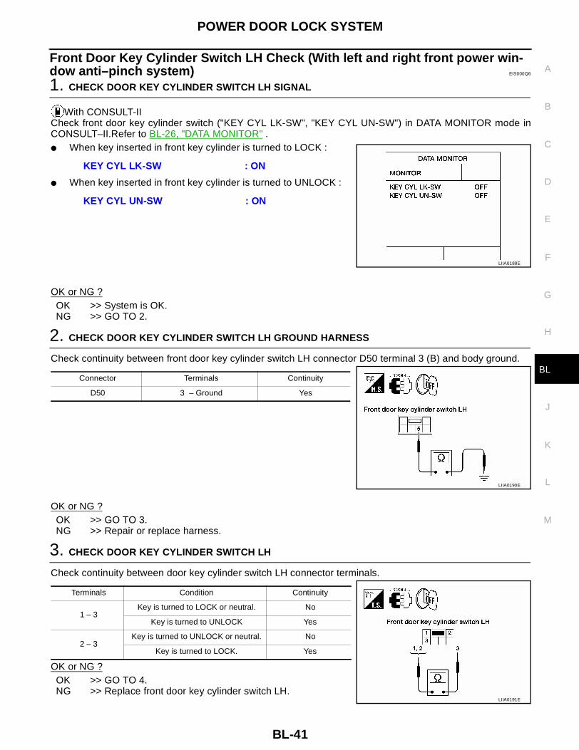
Front Door Key Cylinder Switch LH Check (With left and right front power win-dow anti–pinch system) EIS000Q6
1. CHECK DOOR KEY CYLINDER SWITCH LH SIGNAL
With CONSULT-IICheck front door key cylinder switch ("KEY CYL LK-SW", "KEY CYL UN-SW") in DATA MONITOR mode inCONSULT–II.Refer to BL-26, "DATA MONITOR" . ● When key inserted in front key cylinder is turned to LOCK :
● When key inserted in front key cylinder is turned to UNLOCK :
OK or NG ?OK >> System is OK.NG >> GO TO 2.
2. CHECK DOOR KEY CYLINDER SWITCH LH GROUND HARNESS
Check continuity between front door key cylinder switch LH connector D50 terminal 3 (B) and body ground.
OK or NG ?OK >> GO TO 3.NG >> Repair or replace harness.
3. CHECK DOOR KEY CYLINDER SWITCH LH
Check continuity between door key cylinder switch LH connector terminals.
OK or NG ?OK >> GO TO 4.NG >> Replace front door key cylinder switch LH.
KEY CYL LK-SW : ON
KEY CYL UN-SW : ON
LIIA0188E
Connector Terminals Continuity
D50 3 – Ground Yes
LIIA0190E
Terminals Condition Continuity
1 – 3 Key is turned to LOCK or neutral. No
Key is turned to UNLOCK Yes
2 – 3Key is turned to UNLOCK or neutral. No
Key is turned to LOCK. Yes
LIIA0191E

BL-42
POWER DOOR LOCK SYSTEM
4. CHECK DOOR KEY CYLINDER HARNESS
Check continuity between main power window and door lock/unlock switch connector D7 terminals 4(P/L),5(W/L) and front door key cylinder switch LH connector D50 terminals 1(L), 2(Y) and body ground.
OK or NG ?OK >> Replace main power window and door lock/unlock switch.NG >> Repair or replace harness.
Connector Terminal Connector Terminal Continuity
D7
4D50
2 Should exist
5 1 Should exist
4,5 Ground Should not exist
LIIA0193E
REMOTE KEYLESS ENTRY SYSTEM
BL-43
C
D
E
F
G
H
J
K
L
M
A
B
BL
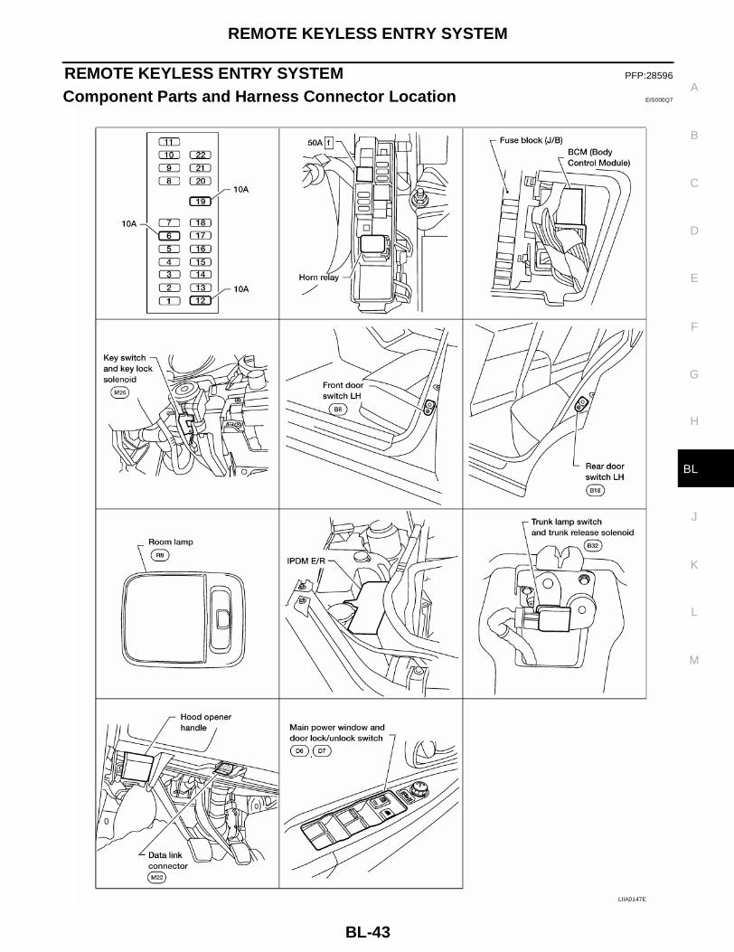
REMOTE KEYLESS ENTRY SYSTEM PFP:28596
Component Parts and Harness Connector Location EIS000Q7
LIIA0147E
BL-44
REMOTE KEYLESS ENTRY SYSTEM
System Description EIS000Q8
INPUTSPower is supplied at all times● to BCM terminal 7● through 50A fusible link (letter f , located in the fuse and fusible link box).● to key switch terminal 3● through 10A fuse [No. 19, located in the fuse block (J/B)].When the key switch is ON (ignition key is inserted in key cylinder), power is supplied● through key switch terminal 4● to BCM terminal 62.When the front door switch LH is ON (door is OPEN), ground is supplied● to BCM terminal 14 and 54 (without vehicle security system).● through front door switch LH terminal 2● to driver door switch case ground.When the front door switch RH is ON (door is OPEN), ground is supplied● to BCM terminal 10● through front door switch RH terminal 2● to front door switch RH case ground.When the rear door switches are ON (door is OPEN), ground is supplied● to BCM terminal 11● through rear door switches terminal 1● to rear door switches case grounds.Key fob signal is inputted to smart entrance control unit (the antenna of the system is combined with BCM).The remote keyless entry system controls operation of the● power door lock● trunk lid opener● interior lamp and step lamps● panic alarm● hazard and horn reminder● keyless power window down (open)
OPERATED PROCEDUREPower Door Lock OperationBCM receives a LOCK signal from key fob. BCM locks all doors with input of LOCK signal from key fob.When an UNLOCK signal is sent from key fob once, driver's door will be unlocked.Then, if an UNLOCK signal is sent from key fob again within 5 seconds, all other door will be unlocked.
Hazard and Horn ReminderBCM output to IPDM E/R for hazard and horn reminder signal as DATA LINE (CAN H line and CAN L line).The hazard and horn reminder has C mode (horn chirp mode) and S mode (non-horn chirp mode).
Operating function of hazard and horn reminder
How to change hazard and horn reminder mode
With CONSULT-IIHazard and horn reminder can be changed using “WORK SUPPORT” mode in “MULTI ANSWER BACK SET".
Without CONSULT-II
C mode S mode
Remote controller operation
Lock Unlock Lock Unlock
Hazard warning lamp flash
Twice Once Twice —
Horn sound Once — — —

REMOTE KEYLESS ENTRY SYSTEM
BL-45
C
D
E
F
G
H
J
K
L
M
A
B
BL
When LOCK and UNLOCK signals are sent from the key fob for more than 2 seconds at the same time, thehazard and horn reminder mode is changed and hazard warning lamp flashes and horn sounds as follows:
Interior Lamp OperationWhen the following input signals are both supplied:● door switch CLOSED (when all the doors are closed);● driver's door LOCKED;Remote keyless entry system turns on interior lamp and ignition illumination (for 30 seconds) with input ofUNLOCK signal from key fob.For detailed description, refer to LT-123, "INTERIOR LAMP TIMER OPERATION" .
Panic Alarm OperationWhen key switch is OFF (when ignition key is not inserted in key cylinder), remote keyless entry system turnson and off horn and headlamp intermittently with input of PANIC ALARM signal from key fob.The alarm automatically turns off after 25 seconds or when BCM receives any signal from key fob.For detailed description, refer to BL-87, "VEHICLE SECURITY (THEFT WARNING) SYSTEM" .
Trunk Lid Opener OperationWhen a TRUNK OPEN signal is sent with key OFF (ignition key removed from key cylinder) from key fob,power is supplied● through BCM terminal 19● to trunk lid opener actuator terminal 3.When power and ground are supplied, trunk lid opener actuator opens trunk lid.
Keyless Power Window Down (open) OperationWhen key fob unlock switch is turned ON with ignition switch OFF, and the switch is detected to be on contin-uously for 3 seconds, the driver's door and passenger's door (with left and right front power window anti-pinchsystem) power windows are simultaneously opened.Power window is operated to open and the operation continues as long as the key fob unlock switch ispressed.
CAN Communication System Description EIS000Q9
CAN (Controller Area Network) is a serial communication line for real time application. It is an on-vehicle mul-tiplex communication line with high data communication speed and excellent error detection ability. Many elec-tronic control units are equipped onto a vehicle, and each control unit shares information and links with othercontrol units during operation (not independent). In CAN communication, control units are connected with 2communication lines (CAN H line, CAN L line) allowing a high rate of information transmission with less wiring.Each control unit transmits/receives data but selectively reads required data only.
SEL153WA

BL-46
REMOTE KEYLESS ENTRY SYSTEM
FOR TCS MODELSSystem diagram
Input/output signal chartT: Transmit R: Receive
LKIA0015E
Signals ECM TCMCOMBINA-
TION METER
BCMABS/TCS
control unitIPDM E/R
Engine speed signal T R R
Engine coolant temperature signal T R
Accelerator pedal position signal T
Fuel consumption monitor signal T R
A/T warning lamp signal T R
A/T position indicator signal R T R R(R range only) R
ABS operation signal R T
TCS operation signal R R T
Air conditioner switch signal R T
Air conditioner compressor signal R T
A/C compressor request signal T R
Cooling fan motor operation signal R T
Cooling fan speed request signal T R
Position lights request R T R
Position lights status R T
Low beam request T R
Low beam status R R T
High beam request R T R
High beam status R R T
Front fog lights request T R
Front fog light status R T
OD cancel switch signal R T R
Brake switch signal R T
Vehicle speed signalR T
R T R
Oil pressure switch R T
Sleep request1 R T
Sleep request2 T R
N range switch signal R T
P range switch signal R T
Seat belt buckle switch signal T R
REMOTE KEYLESS ENTRY SYSTEM
BL-47
C
D
E
F
G
H
J
K
L
M
A
B
BL
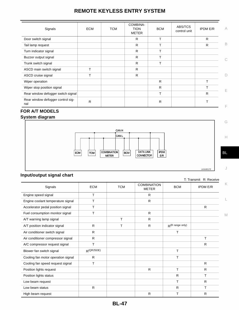
FOR A/T MODELSSystem diagram
Input/output signal chartT: Transmit R: Receive
Door switch signal R T R
Tail lamp request R T R
Turn indicator signal R T
Buzzer output signal R T
Trunk switch signal R T
ASCD main switch signal T R
ASCD cruise signal T R
Wiper operation R T
Wiper stop position signal R T
Rear window defogger switch signal T R
Rear window defogger control sig-nal
R R T
Signals ECM TCMCOMBINA-
TION METER
BCMABS/TCS
control unitIPDM E/R
LKIA0017E
Signals ECM TCMCOMBINATION
METERBCM IPDM E/R
Engine speed signal T R
Engine coolant temperature signal T R
Accelerator pedal position signal T R
Fuel consumption monitor signal T R
A/T warning lamp signal T R
A/T position indicator signal R T R R(R range only)
Air conditioner switch signal R T
Air conditioner compressor signal R T
A/C compressor request signal T R
Blower fan switch signal R(QR25DE) T
Cooling fan motor operation signal R T
Cooling fan speed request signal T R
Position lights request R T R
Position lights status R T
Low beam request T R
Low beam status R R T
High beam request R T R

BL-48
REMOTE KEYLESS ENTRY SYSTEM
FOR M/T MODELSSystem diagram
Input/output signal chartT: Transmit R: Receive
High beam status R R T
Front fog lights request T R
Front fog light status R T
OD cancel switch signal R T R
Brake switch signal R T
Vehicle speed signalR T
R T R
Oil pressure switch R T
Sleep request1 R T
Sleep request2 T R
N range switch signal R T
P range switch signal R T
Seat belt buckle switch signal T R
Door switch signal R T R
Tail lamp request R T R
Turn indicator signal R T
Buzzer output signal R T
Trunk switch signal R T
ASCD main switch signal T R
ASCD cruise signal T R
Wiper operation R T
Wiper stop position signal R T
Rear window defogger switch signal T R
Rear window defogger control signal R R T
Signals ECM TCMCOMBINATION
METERBCM IPDM E/R
LKIA0018E
Signals ECMCOMBINATION
METERBCM IPDM E/R
Engine speed signal T
Engine coolant temperature signal T
Fuel consumption monitor signal T
Air conditioner switch signal R T
Air conditioner compressor signal R T
A/C compressor request signal T R

REMOTE KEYLESS ENTRY SYSTEM
BL-49
C
D
E
F
G
H
J
K
L
M
A
B
BL
Blower fan switch signal R(QR25DE) T
Cooling fan motor operation signal R T
Cooling fan speed request signal T R
Position lights request R T R
Position lights status R T
Low beam request T R
Low beam status R R T
High beam request R T R
High beam status R R T
Front fog lights request T R
Front fog light status R T
Vehicle speed signal R T
Oil pressure switch R T
Sleep request1 R T
Sleep request2 T R
Seat belt buckle switch signal T R
Door switch signal R T R
Tail lamp request R T R
Turn indicator signal R T
Buzzer output signal R T
Trunk switch signal R T
ASCD main switch signal T R
ASCD cruise signal T R
Wiper operation R T
Wiper stop position signal R T
Rear window defogger switch signal T R
Rear window defogger control signal R R T
Signals ECMCOMBINATION
METERBCM IPDM E/R

BL-50
REMOTE KEYLESS ENTRY SYSTEM
Schematic EIS000QA
LIWA0035E

REMOTE KEYLESS ENTRY SYSTEM
BL-51
C
D
E
F
G
H
J
K
L
M
A
B
BL
Wiring Diagram — KEYLES— EIS000QB
FIG. 1
LIWA0036E
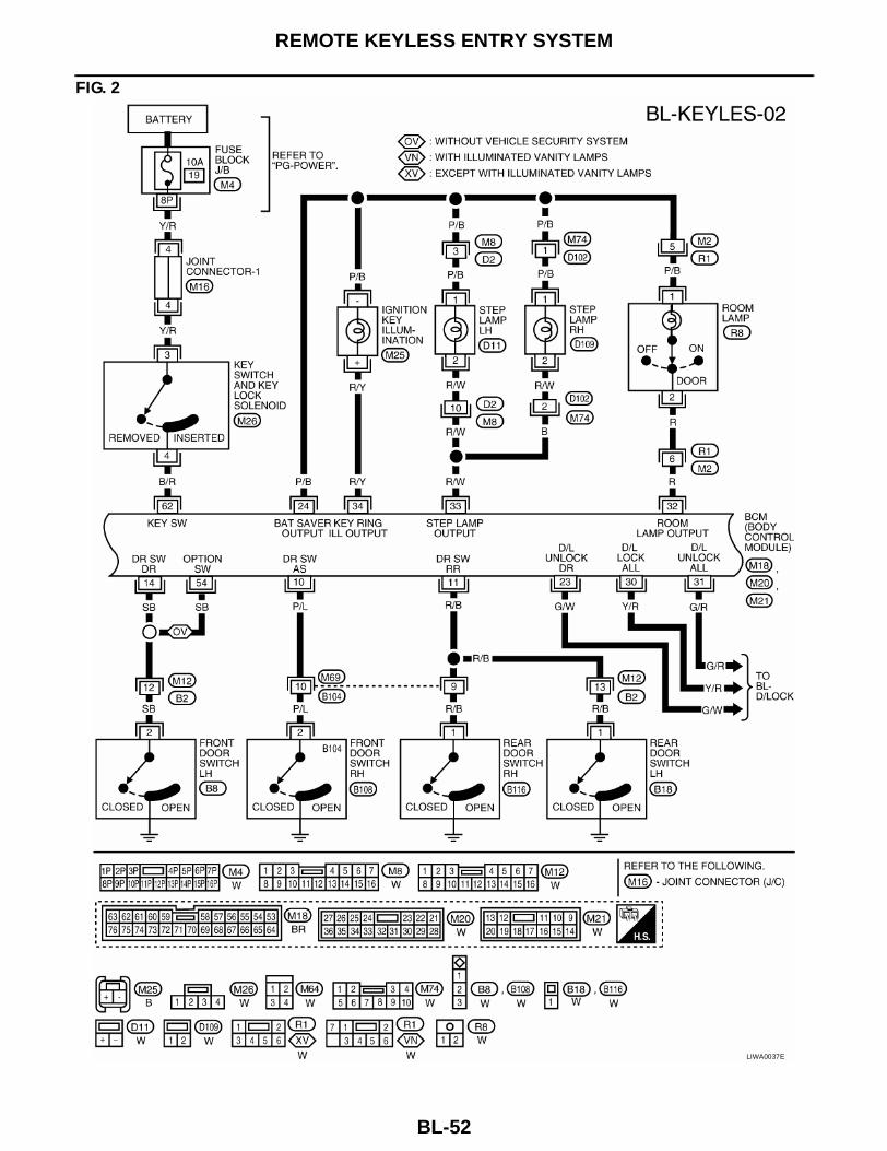
BL-52
REMOTE KEYLESS ENTRY SYSTEM
FIG. 2
LIWA0037E

REMOTE KEYLESS ENTRY SYSTEM
BL-53
C
D
E
F
G
H
J
K
L
M
A
B
BL
FIG. 3
LIWA0038E

BL-54
REMOTE KEYLESS ENTRY SYSTEM
FIG. 4
LIWA0039E

REMOTE KEYLESS ENTRY SYSTEM
BL-55
C
D
E
F
G
H
J
K
L
M
A
B
BL
Terminals and Reference Value for BCM EIS000QC
CONSULT-II Function EIS000QD
● The following functions are executed by combining data received and command transmitted via the com-munication line from the BCM.
TERMINAL WIRE
COLORITEM CONDITION
VOLTAGE(Approximate value)
7 W/B Power source (BAT) — Battery voltage
8 B Ground — —
10 P/L Front door switch RH Door Close (OFF) → Open (ON) Battery voltage → 0V
11 R/B Rear door switch RH and LH Door Close (OFF) → Open (ON) Battery voltage → 0V
14 SBFront door switch LH(with vehicle security system)
Door Close (OFF) → Open (ON) Battery voltage → 0V
19 P Trunk release solenoidWhen trunk lid release solenoid is operated using key fob (ON → OFF)
0V → Battery voltage
23 G/W Driver door lock actuatorDoor lock & unlock switch(Neutral → Unlock)
0V → Battery voltage
24 P/BBattery saver(Interior lamp)
Battery saver does operated → Does not operated (ON → OFF)
Battery voltage → 0V
27 B Ground — —
30 Y/R Door lock actuatorsDoor lock & unlock switch(Neutral → Lock)
0V → Battery voltage
31 G/RPassenger and rear doors lock actuator
Door lock & unlock switch(Neutral → Unlock)
0V → Battery voltage
32 R Room lampWhen doors are locked using key fob(Lamp switch in "DOOR" position )
Battery voltage
33 R/W Step lamp LH and RHWhen doors are unlocked using key fob(OFF → Unlock)
Battery voltage → 0V
34 R/Y Ignition key illuminationWhen doors are unlocked using key fob(OFF → Unlock)
Battery voltage → 0V
35 G Ignition switch (ON) — Battery voltage
36 PU Ignition switch (ACC) — Battery voltage
54 SBFront door switch LH(without vehicle security sys-tem)
Door Close (OFF) → Open (ON) Battery voltage → 0V
62 B/R Ignition key switch (insert) Key inserted → Key removed from key cylinder
Battery voltage → 0V
63 B Ground — —
70 L CAN H — —
71 Y CAN L — —
74 Y/G Anti-pinch serial link —
LIIA0166E
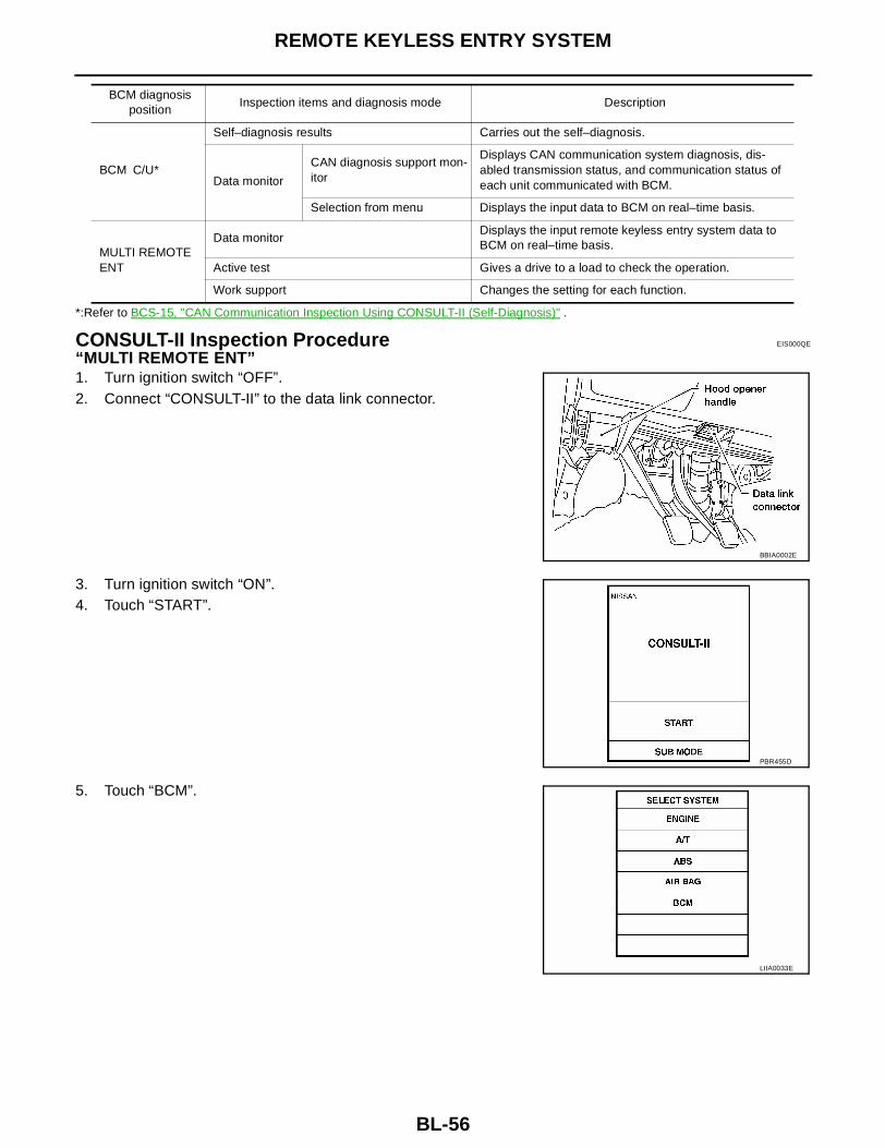
BL-56
REMOTE KEYLESS ENTRY SYSTEM
*:Refer to BCS-15, "CAN Communication Inspection Using CONSULT-II (Self-Diagnosis)" .
CONSULT-II Inspection Procedure EIS000QE
“MULTI REMOTE ENT”1. Turn ignition switch “OFF”.2. Connect “CONSULT-II” to the data link connector.
3. Turn ignition switch “ON”.4. Touch “START”.
5. Touch “BCM”.
BCM diagnosis position
Inspection items and diagnosis mode Description
BCM C/U*
Self–diagnosis results Carries out the self–diagnosis.
Data monitor
CAN diagnosis support mon-itor
Displays CAN communication system diagnosis, dis-abled transmission status, and communication status of each unit communicated with BCM.
Selection from menu Displays the input data to BCM on real–time basis.
MULTI REMOTE ENT
Data monitorDisplays the input remote keyless entry system data to BCM on real–time basis.
Active test Gives a drive to a load to check the operation.
Work support Changes the setting for each function.
BBIA0002E
PBR455D
LIIA0033E
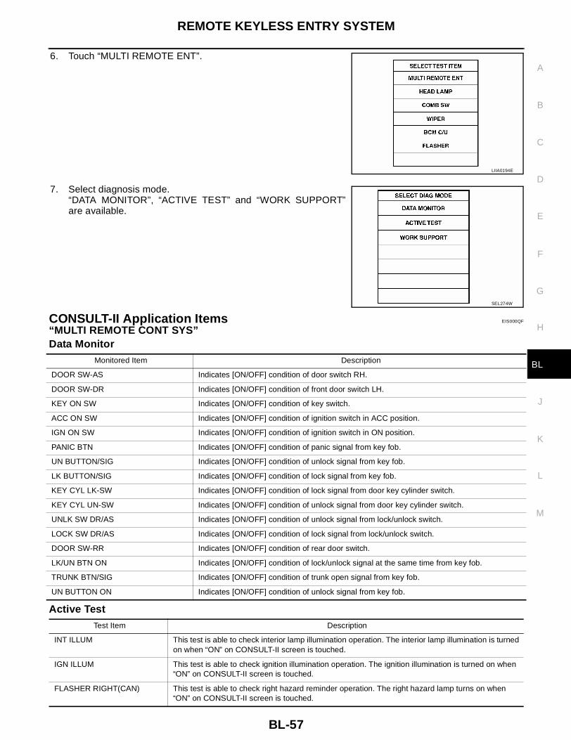
REMOTE KEYLESS ENTRY SYSTEM
BL-57
C
D
E
F
G
H
J
K
L
M
A
B
BL
6. Touch “MULTI REMOTE ENT”.
7. Select diagnosis mode.“DATA MONITOR”, “ACTIVE TEST” and “WORK SUPPORT”are available.
CONSULT-II Application Items EIS000QF
“MULTI REMOTE CONT SYS”Data Monitor
Active Test
LIIA0194E
SEL274W
Monitored Item Description
DOOR SW-AS Indicates [ON/OFF] condition of door switch RH.
DOOR SW-DR Indicates [ON/OFF] condition of front door switch LH.
KEY ON SW Indicates [ON/OFF] condition of key switch.
ACC ON SW Indicates [ON/OFF] condition of ignition switch in ACC position.
IGN ON SW Indicates [ON/OFF] condition of ignition switch in ON position.
PANIC BTN Indicates [ON/OFF] condition of panic signal from key fob.
UN BUTTON/SIG Indicates [ON/OFF] condition of unlock signal from key fob.
LK BUTTON/SIG Indicates [ON/OFF] condition of lock signal from key fob.
KEY CYL LK-SW Indicates [ON/OFF] condition of lock signal from door key cylinder switch.
KEY CYL UN-SW Indicates [ON/OFF] condition of unlock signal from door key cylinder switch.
UNLK SW DR/AS Indicates [ON/OFF] condition of unlock signal from lock/unlock switch.
LOCK SW DR/AS Indicates [ON/OFF] condition of lock signal from lock/unlock switch.
DOOR SW-RR Indicates [ON/OFF] condition of rear door switch.
LK/UN BTN ON Indicates [ON/OFF] condition of lock/unlock signal at the same time from key fob.
TRUNK BTN/SIG Indicates [ON/OFF] condition of trunk open signal from key fob.
UN BUTTON ON Indicates [ON/OFF] condition of unlock signal from key fob.
Test Item Description
INT ILLUM This test is able to check interior lamp illumination operation. The interior lamp illumination is turned on when “ON” on CONSULT-II screen is touched.
IGN ILLUM This test is able to check ignition illumination operation. The ignition illumination is turned on when “ON” on CONSULT-II screen is touched.
FLASHER RIGHT(CAN) This test is able to check right hazard reminder operation. The right hazard lamp turns on when “ON” on CONSULT-II screen is touched.

BL-58
REMOTE KEYLESS ENTRY SYSTEM
Work Support
Hazard and horn reminder mode
Auto locking function mode
Panic alarm operation mode
Trunk open operation mode
Power window down operation mode
Trouble Diagnosis Procedure EIS000QG
1. Check the trouble symptom and customer's requests.2. Understand outline of system. Refer to BL-44, "System Description" .
FLASHER LEFT(CAN) This test is able to check left hazard reminder operation. The left hazard lamp turns on when “ON” on CONSULT-II screen is touched.
HORN This test is able to check panic alarm and horn reminder operations. The alarm activate for 0.5 sec-onds after “ON” on CONSULT-II screen is touched.
HEAD LAMP(HI) This test is able to check headlamps panic alarm operation. The headlamp illuminates for 0.5 sec-onds after “ON” on CONSULT-II screen is touched.
TRUNK/BACK DOOR This test is able to check trunk lid opener actuator operation. The trunk is unlocked when “ON” on CONSULT-II screen is touched.
Test Item Description
Test Item Description
REMO CONT ID CONFIR It can be checked whether key fob ID code is registered or not in this mode.
REMO CONT ID REGIST Key fob ID code can be registered.
REMO CONT ID ERASUR Key fob ID code can be erased.
MULTI ANSWER BACK SETHazard and horn reminder mode can be changed in this mode. The reminder mode will be changed when “MODE SET” on CONSULT-II screen is touched.
AUTO LOCK SETAuto locking function mode can be changed in this mode. The function mode will be changed when "MODE SET" on CONSULT-II screen is touched.
PANIC ALRM SETPanic alarm operation mode can be changed in this mode. The operaition mode will be changed when "MODE SET" on CONSULT-II screen is touched.
TRUNK OPEN SETTrunk lid opener operation mode can be changed in this mode. The operation mode will be changed when "MODE SET" on CONSULT-II screen is touched.
PW DOWN SETKeyless power window down (open) operation mode can be changed in this mode. The operation mode will be changed when "MODE SET" on CONSULT-II screen is touched.
MODE 1(C mode)
MODE 2(S mode)
MODE 3 MODE 4 MODE 5 MODE 6
Key foboperation
Lock Unlock Lock Unlock Lock Unlock Lock Unlock Lock Unlock Lock Unlock
Hazard warning lamp flash
Twice Once Twice — — — Twice Once Twice — — Once
Horn sound Once — — — — — — — Once — Once —
MODE 1 MODE 2 MODE 3
Auto locking function 5 minutes Nothing 1 minuites
MODE 1 MODE 2 MODE 3
Key fob operation 0.5 seconds Nothing 1.5 seconds
MODE 1 MODE 2 MODE 3
Key fob operation 0.5 seconds Nothing 1.5 seconds
MODE 1 MODE 2 MODE 3
Key fob operation 3 seconds Nothing 5 seconds

REMOTE KEYLESS ENTRY SYSTEM
BL-59
C
D
E
F
G
H
J
K
L
M
A
B
BL
3. Confirm that power door lock system operates normally. Refer to BL-16, "POWER DOOR LOCK SYS-TEM" .
4. Perform pre-diagnosis inspection. Refer to BL-59, "Pre-Diagnosis Inspection" .5. Refer to trouble diagnosis chart by symptom, repair or replace any malfunctioning parts. Refer to BL-59,
"Trouble Diagnoses" .6. Inspection End.
Pre-Diagnosis Inspection EIS000QH
BCM POWER SUPPLY AND GROUND CIRCUIT INSPECTION
1. FUSE INSPECTION
● Check the following fuses and fusible link in the fuse block (J/B) and fuse and fusible link box.
OK or NGOK >> GO TO 2.NG >> Replace the fuse or fusible link.
2. POWER SUPPLY CIRCUIT INSPECTION
Disconnect BCM connector, and connect vehicle-side connector terminals shown below to positive probe andbody ground to negative probe. Measure voltage.
OK or NGOK >> GO TO 3.NG >> Replace applicable power circuit harness.
3. GROUND CIRCUIT INSPECTION
Check continuity between BCM vehicle-side connector and body ground.
OK or NGOK >> Power supply and ground circuits are normal.NG >> Replace BCM ground circuit harness.
Trouble Diagnoses EIS000QI
SYMPTOM CHARTNOTE:● Always check key fob battery before replacing key fob.● The panic alarm operation and trunk lid opener operation of remote keyless entry system do not activate
with the ignition key inserted in the ignition key cylinder.● Use Remote Keyless Entry Tester J-43241 (follow instructions on tester) to check operation of key fob
before replacing key fob.
Unit Terminal No. Signal name No. Location
BCM
7 Battery power supply f Fuse and fuslible link box
36 ACC power supply 6 Fuse block (J/B)
35 IGN power supply 12 Fuse block (J/B)
Unit Terminal No. Signal name Ignition switch Voltage
BCM
7 Battery power supply OFF Battery voltage
36 ACC power supply ACC Battery voltage
35 IGN power supply ON Battery voltage
Unit Terminal No. Signal name Ignition switch Continuity
BCM 8, 27, 63 Ground OFF Yes

BL-60
REMOTE KEYLESS ENTRY SYSTEM
Symptom Diagnoses/service procedureReference
page
All function of remote keyless entry system do not operate.
1. Key fob battery and function check (use Remote Keyless Entry Tester J-43241)
BL-61
2. Replace key fob (use Remote Keyless Entry Tester J-43241). Refer to ID Code Entry Procedure.
NOTE:If the result of key fob function check with CONSULT-II is OK, Key fob is not malfunctioning.
BL-71
The new ID of key fob cannot be entered.
1. Key fob battery and function check (use Remote Keyless Entry Tester J-43241)
BL-61
2. Key switch (insert) check BL-63
3. Door switch check BL-62
4. Replace key fob (use Remote Keyless Entry Tester J-43241). Refer to ID Code Entry Procedure.
NOTE:If the result of key fob function check with CONSULT-II is OK, Key fob is not malfunctioning.
BL-71
Door lock or unlock does not function.(If the power door lock system does not operate manually, check power door lock system. Refer to BL-16, "POWER DOOR LOCK SYSTEM" )
1. Key fob battery and function check (use Remote Keyless Entry Tester J-43241)
BL-61
2. Replace key fob (use Remote Keyless Entry Tester J-43241). Refer to ID Code Entry Procedure .
NOTE:If the result of key fob function check with CONSULT-II is OK, Key fob is not malfunctioning.
BL-71
Hazard and horn reminder does not activate prop-erly when pressing lock or unlock button of key fob.
1. Hazard reminder check BL-65
2. Horn reminder check BL-67
3. Door switch check BL-62
4. Replace BCM. —
Room lamp, ignition illumination and step lamp operation do not activate properly.
1. Room lamp operation check BL-68
2. Ignition illumination operation check BL-69
3.Step lamp operation check BL-70
4. Door switch check BL-62
Panic alarm (horn and headlamp) does not activate when panic alarm button is continuously pressed.
1. Key fob battery and function check (use Remote Keyless Entry Tester J-43241)
BL-61
2. Vehicle security operation check.Refer to Vehicle security system.
BL-87
3. Key switch (insert) check BL-63
4. Replace key fob (use Remote Keyless Entry Tester J-43241). Refer to ID Code Entry Procedure.
NOTE:If the result of key fob function check with CONSULT-II is OK, Key fob is not malfunctioning.
BL-71
Trunk lid does not open when trunk opener button is continuously pressed.
1. Key fob battery and function check (use Remote Keyless Entry Tester J-43241)
BL-61
2. Trunk release solenoid check BL-64
3. Key switch (insert) check BL-63
4. Replace BCM. —

REMOTE KEYLESS ENTRY SYSTEM
BL-61
C
D
E
F
G
H
J
K
L
M
A
B
BL
Key Fob Battery and Function Check EIS000QJ
1. CHECK KEY FOB BATTERY
Remove battery and measure voltage across battery positive and negative terminals, (+) and (−).
NOTE:Key fob does not function if battery is not set correctly.OK or NG?OK >> GO TO 2NG >> Replace battery.
2. CHECK KEY FOB FUNCTION
With CONSULT-IICheck key fob function in “DATA MONITOR” mode with CONSULT-II.When pushing each button of key fob, the corresponding monitor item shouldbe turned as follows.
OK or NG?OK >> Key fob is OK. Further inspection is necessary. Refer to BL-59, "SYMPTOM CHART" .NG >> Replace key fob.
Voltage : 2.5V - 3.0V
SEL237W
Condition Monitor item
Pushing LOCK LK BUTTON/SIG : ON
Pushing UNLOCK UN BUTTON/SIG : ON
Pushing TRUNK TRUNK BTN/SIG : ON
Pushing PANIC PANIC BTN : ON
Pushing LOCK and UNLOCK at the same time
LK/UN BTN ON : ON LIIA0195E
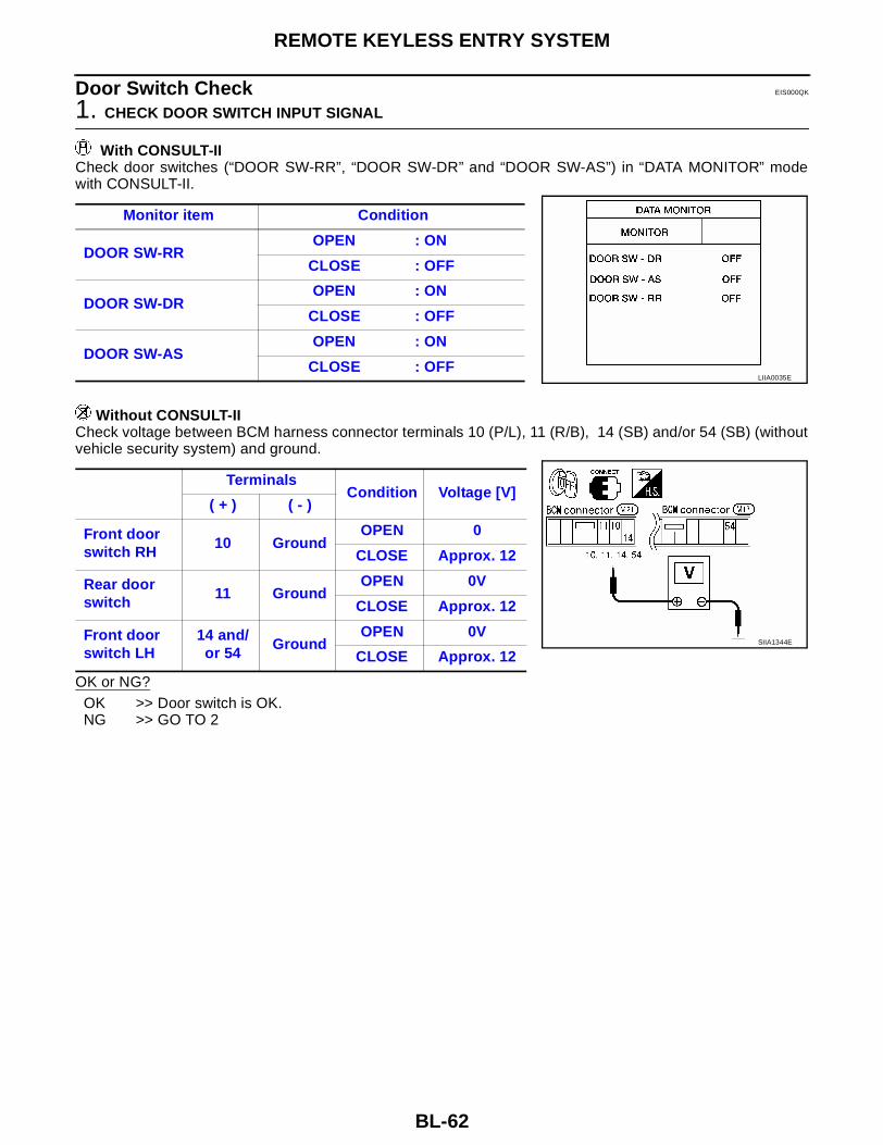
BL-62
REMOTE KEYLESS ENTRY SYSTEM
Door Switch Check EIS000QK
1. CHECK DOOR SWITCH INPUT SIGNAL
With CONSULT-IICheck door switches (“DOOR SW-RR”, “DOOR SW-DR” and “DOOR SW-AS”) in “DATA MONITOR” modewith CONSULT-II.
Without CONSULT-IICheck voltage between BCM harness connector terminals 10 (P/L), 11 (R/B), 14 (SB) and/or 54 (SB) (withoutvehicle security system) and ground.
OK or NG?OK >> Door switch is OK.NG >> GO TO 2
Monitor item Condition
DOOR SW-RROPEN : ON
CLOSE : OFF
DOOR SW-DROPEN : ON
CLOSE : OFF
DOOR SW-ASOPEN : ON
CLOSE : OFFLIIA0035E
TerminalsCondition Voltage [V]
( + ) ( - )
Front door switch RH
10 GroundOPEN 0
CLOSE Approx. 12
Rear door switch
11 GroundOPEN 0V
CLOSE Approx. 12
Front door switch LH
14 and/or 54
GroundOPEN 0V
CLOSE Approx. 12SIIA1344E
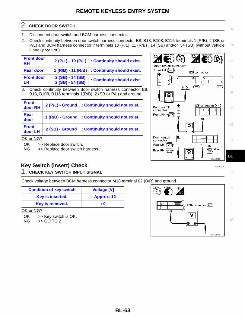
REMOTE KEYLESS ENTRY SYSTEM
BL-63
C
D
E
F
G
H
J
K
L
M
A
B
BL
2. CHECK DOOR SWITCH
1. Disconnect door switch and BCM harness connector.2. Check continuity between door switch harness connector B8, B18, B108, B116 terminals 1 (R/B), 2 (SB or
P/L) and BCM harness connector ? terminals 10 (P/L), 11 (R/B) , 14 (SB) and/or 54 (SB) (without vehiclesecurity system).
3. Check continuity between door switch harness connector B8,B18, B108, B116 terminals 1(R/B), 2 (SB or P/L) and ground.
OK or NG?OK >> Replace door switch.NG >> Replace door switch harness.
Key Switch (insert) Check EIS000QL
1. CHECK KEY SWITCH INPUT SIGNAL
Check voltage between BCM harness connector M18 terminal 62 (B/R) and ground.
OK or NG?OK >> Key switch is OK.NG >> GO TO 2
Front door RH
2 (P/L) - 10 (P/L) : Continuity should exist.
Rear door 1 (R/B) - 11 (R/B) : Continuity should exist.
Front door LH
2 (SB) - 14 (SB)2 (SB) - 54 (SB)
: Continuity should exist.
Front door RH
2 (P/L) - Ground : Continuity should not exist.
Rear door
1 (R/B) - Ground : Continuity should not exist.
Front door LH
2 (SB) - Ground : Continuity should not exist.
SIIA1351E
Condition of key switch Voltage [V]
Key is inserted. : Approx. 12
Key is removed. : 0
SIIA1354E

BL-64
REMOTE KEYLESS ENTRY SYSTEM
2. CHECK KEY SWITCH (INSERT)
Check continuity between key switch connector M26 terminals 3 and 4.
OK or NG?OK >> Check the following.
● 10A fuse [No. 19, located in fuse block (J/B)]● Harness for open or short between key switch and
fuse● Harness for open or short between BCM and key
switchNG >> Replace key switch.
Trunk Release Solenoid Check EIS000QM
1. CHECK TRUNK LID OPENER
Check trunk release operation with trunk lid opener switch.NOTE:First check trunk lid opener cancel switch position. Refer to BL-85, "TRUNK LID OPENER"Does trunk lid open?
Yes >> GO TO 2.No >> Check trunk release solenoid and the circuit.
2. CHECK TRUNK LID OPENER ACTUATOR OPERATION
With CONSULT-II1. Select “ACTIVE TEST” in “MULTI REMOTE ENT” with CONSULT-II.2. Select “TRUNK/BACK DOOR” and touch “ON”.
NOTE:If CONSULT-II is not available, skip this procedure and go to thenext step.
OK or NG?OK >> Trunk lid opener actuator circuit is OK.NG >> Check harness for open or short between BCM and
trunk lid opener actuator.
Condition of key switch Continuity
Key is inserted. Yes
Key is removed. No
SIIA1355E
Trunk release solenoid should operate.
LIIA0196E

REMOTE KEYLESS ENTRY SYSTEM
BL-65
C
D
E
F
G
H
J
K
L
M
A
B
BL
3. CHECK TRUNK LID OPENER ACTUATOR CIRCUIT
Without CONSULT-II1. Disconnect trunk lamp switch and trunk release solenoid connector.2. Check voltage between trunk lamp switch and trunk release solenoid harness connector B32 terminal 3
(P) and ground.
3. Check continuity between trunk lamp switch and trunk releasesolenoid harness connector B32 terminal 4 (B) and ground.
OK or NG?OK >> Replace trunk release solenoid.No >> Check the following.
1. Harness for open or short between BCM and trunkrelease solenoid
2. Harness for open or short between trunk lamp switchand trunk release solenoid and ground
3. Replace BCM
Hazard Reminder Check EIS000QN
1. CHECK HAZARD INDICATOR
Check if hazard indicator flashes with hazard switch.Does hazard indicator operate?Yes >> GO TO 2No >> Check “hazard indicator” Refer to LT-80, "TURN SIGNAL AND HAZARD WARNING LAMPS" .
3 (P) - Ground : Battery voltage should exist.
4 (B) - Ground : Continuity should exist.
SIIA1358E
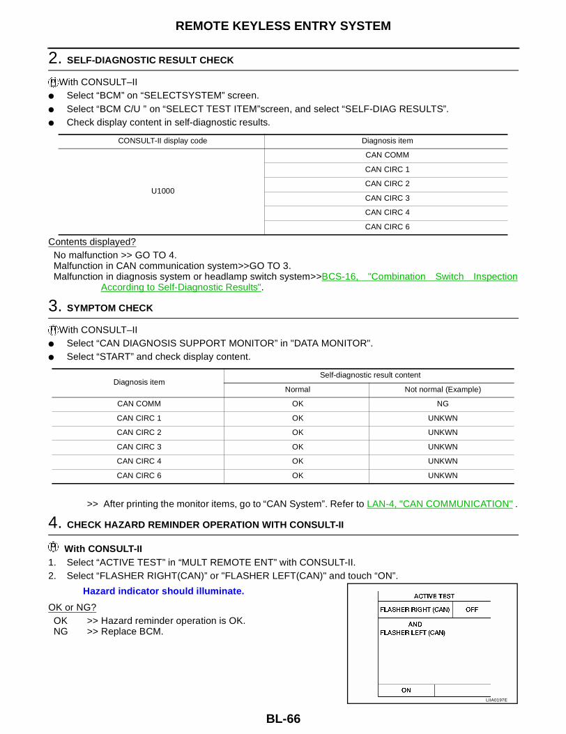
BL-66
REMOTE KEYLESS ENTRY SYSTEM
2. SELF-DIAGNOSTIC RESULT CHECK
With CONSULT–II● Select “BCM” on “SELECTSYSTEM” screen.● Select “BCM C/U ” on “SELECT TEST ITEM”screen, and select “SELF-DIAG RESULTS”.● Check display content in self-diagnostic results.
Contents displayed?No malfunction >> GO TO 4.Malfunction in CAN communication system>>GO TO 3.Malfunction in diagnosis system or headlamp switch system>>BCS-16, "Combination Switch Inspection
According to Self-Diagnostic Results".
3. SYMPTOM CHECK
With CONSULT–II● Select “CAN DIAGNOSIS SUPPORT MONITOR” in "DATA MONITOR".● Select “START” and check display content.
>> After printing the monitor items, go to “CAN System”. Refer to LAN-4, "CAN COMMUNICATION" .
4. CHECK HAZARD REMINDER OPERATION WITH CONSULT-II
With CONSULT-II1. Select “ACTIVE TEST” in “MULT REMOTE ENT” with CONSULT-II.2. Select “FLASHER RIGHT(CAN)” or "FLASHER LEFT(CAN)" and touch “ON”.
OK or NG?OK >> Hazard reminder operation is OK.NG >> Replace BCM.
CONSULT-II display code Diagnosis item
U1000
CAN COMM
CAN CIRC 1
CAN CIRC 2
CAN CIRC 3
CAN CIRC 4
CAN CIRC 6
Diagnosis itemSelf-diagnostic result content
Normal Not normal (Example)
CAN COMM OK NG
CAN CIRC 1 OK UNKWN
CAN CIRC 2 OK UNKWN
CAN CIRC 3 OK UNKWN
CAN CIRC 4 OK UNKWN
CAN CIRC 6 OK UNKWN
Hazard indicator should illuminate.
LIIA0197E

REMOTE KEYLESS ENTRY SYSTEM
BL-67
C
D
E
F
G
H
J
K
L
M
A
B
BL
Horn Reminder Check EIS000QO
1. CHECK HORN
Check if horn sounds with horn switch.Does horn operate?Yes >> GO TO 2.No >> Check horn circuit. Refer to WW-32, "HORN" .
2. SELF-DIAGNOSTIC RESULT CHECK
With CONSULT–II● Select “BCM” on “SELECT SYSTEM” screen.● Select “BCM C/U ” on “SELECT TEST ITEM”screen, and select “SELF-DIAG RESULTS”.● Check display content in self-diagnostic results.
Contents displayed?No malfunction >> GO TO 4.Malfunction in CAN communication system >> GO TO 3.Malfunction in diagnosis system or head lamp switch system >> BCS-16, "Combination Switch Inspection
According to Self-Diagnostic Results" .
3. SYMPTOM CHECK
With CONSULT–II● Select “CAN DIAGNOSIS SUPPORT MONITOR” in "DATA MONITOR".● Select “START” and check display content.
>> After printing the monitor items, go to “CAN System”. Refer to LAN-4, "CAN COMMUNICATION" .
CONSULT-II display code Diagnosis item
U1000
CAN COMM
CAN CIRC 1
CAN CIRC 2
CAN CIRC 3
CAN CIRC 4
CAN CIRC 6
Diagnosis itemSelf-diagnostic result content
Normal Not normal (Example)
CAN COMM OK NG
CAN CIRC 1 OK UNKWN
CAN CIRC 2 OK UNKWN
CAN CIRC 3 OK UNKWN
CAN CIRC 4 OK UNKWN
CAN CIRC 6 OK UNKWN

BL-68
REMOTE KEYLESS ENTRY SYSTEM
4. CHECK HORN REMINDER OPERATION WITH CONSULT-II
With CONSULT-II1. Select “ACTIVE TEST” in “MULTI REMOTE ENT” with CONSULT-II.2. Select “HORN” and touch ON.
OK or NG?OK >> Horn reminder operation is OK.NG >> Replace BCM.
Interior Lamp Operation Check EIS000QP
1. CHECK INTERIOR LAMP
Check if the interior lamp switch is in the ON position and the lamp illuminates.Does interior lamp illuminate?
Yes >> GO TO 2No >> Check interior room lamp circuit. Refer to LT-123, "INTERIOR ROOM LAMP" .
2. CHECK INTERIOR LAMP OPERATION
With CONSULT-II1. Select “ACTIVE TEST” in “MULTI-REMOTE CONT SYS” with CONSULT-II.2. Select “INT ILLUM” and touch ON.
Without CONSULT-II Push unlock button of key fob with all doors closed and driver's door locked, and check voltage between BCMharness connector M20 terminal 32 (R) and ground.
OK or NGOK >> System is OK.NG >> Check harness open or short between BCM and interior
lamp.
Horn should sound.
LIIA0198E
Interior lamp should illminate.
LIIA0199E
Key Fob Voltage [V]
Unlock button is pushed. : 0 (Approx. 30 seconds)
Unlock button is not pushed : Battery voltage
SIIA1366E
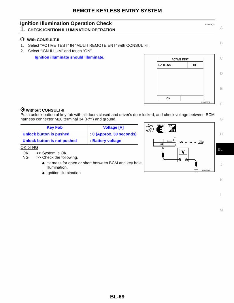
REMOTE KEYLESS ENTRY SYSTEM
BL-69
C
D
E
F
G
H
J
K
L
M
A
B
BL
Ignition Illumination Operation Check EIS000QQ
1. CHECK IGNITION ILLUMINATION OPERATION
With CONSULT-II1. Select “ACTIVE TEST” IN “MULTI REMOTE ENT” with CONSULT-II.2. Select “IGN ILLUM” and touch “ON”.
Without CONSULT-IIPush unlock button of key fob with all doors closed and driver's door locked, and check voltage between BCMharness connector M20 terminal 34 (R/Y) and ground.
OK or NGOK >> System is OK.NG >> Check the following.
● Harness for open or short between BCM and key holeillumination.
● Ignition illumination
Ignition illuminate should illuminate.
LIIA0200E
Key Fob Voltage [V]
Unlock button is pushed. : 0 (Approx. 30 seconds)
Unlock button is not pushed : Battery voltage
SIIA1368E

BL-70
REMOTE KEYLESS ENTRY SYSTEM
Step Lamp Operation Check EIS000QR
1. CHECK STEP LAMP OPERATION
With CONSULT-II1. Select “ACTIVE TEST” IN “MULTI REMOTE ENT” with CONSULT-II.2. Select “INT ILLUM” and touch “ON”.
Without CONSULT-IIPush unlock button of key fob with all doors closed and driver's door locked, and check voltage between BCMharness connector M20 terminal 33 (R/W) and ground.
OK or NGOK >> System is OK.NG >> Check the following.
● Harness for open or short between BCM and steplamp.
● Step lamp
Step lamp should illuminate.
LIIA0199E
Key Fob Voltage [V]
Unlock button is pushed. : 0 (Approx. 30 seconds)
Unlock button is not pushed : Battery voltage
SIIA1368E
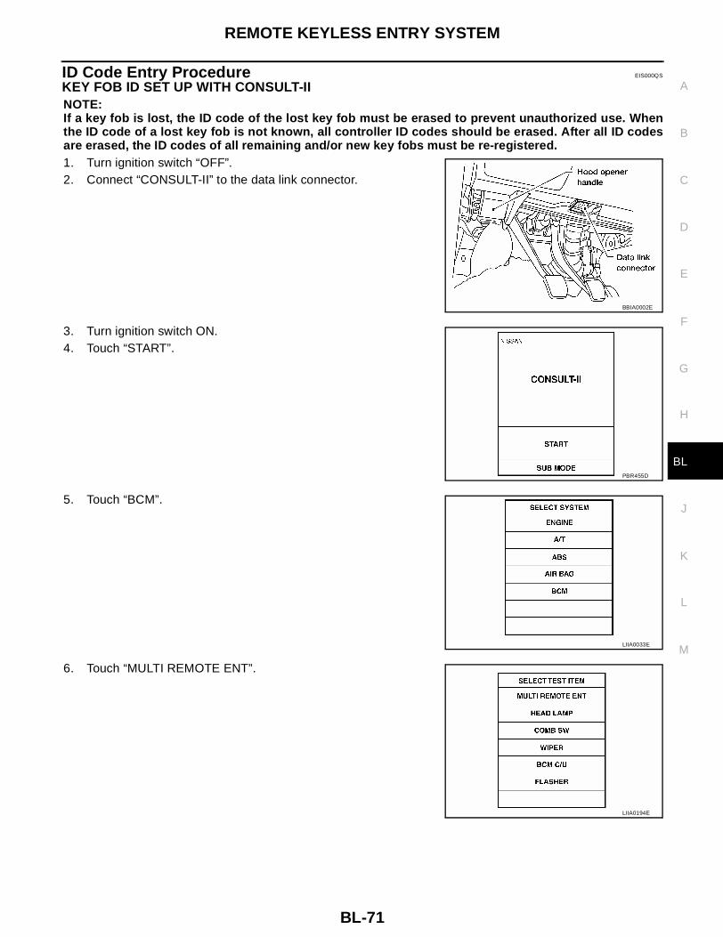
REMOTE KEYLESS ENTRY SYSTEM
BL-71
C
D
E
F
G
H
J
K
L
M
A
B
BL
ID Code Entry Procedure EIS000QS
KEY FOB ID SET UP WITH CONSULT-IINOTE:If a key fob is lost, the ID code of the lost key fob must be erased to prevent unauthorized use. Whenthe ID code of a lost key fob is not known, all controller ID codes should be erased. After all ID codesare erased, the ID codes of all remaining and/or new key fobs must be re-registered.1. Turn ignition switch “OFF”.2. Connect “CONSULT-II” to the data link connector.
3. Turn ignition switch ON.4. Touch “START”.
5. Touch “BCM”.
6. Touch “MULTI REMOTE ENT”.
BBIA0002E
PBR455D
LIIA0033E
LIIA0194E

BL-72
REMOTE KEYLESS ENTRY SYSTEM
7. Touch “WORK SUPPORT”.
8. The items are shown on the figure at left can be set up.● “REMO CONT ID CONFIR”
Use this mode to confirm if a key fob ID code is registered ornot.
● “REMO CONT ID REGIST”Use this mode to register a key fob ID code.NOTE:Register the ID code when key fob or BCM is replaced, orwhen additional key fob is required.
● “REMO CONT ID ERASUR”Use this mode to erase a key fob ID code.
SEL274W
LIIA0207E

REMOTE KEYLESS ENTRY SYSTEM
BL-73
C
D
E
F
G
H
J
K
L
M
A
B
BL
KEY FOB ID SET UP WITHOUT CONSULT-II
LIIA0208E
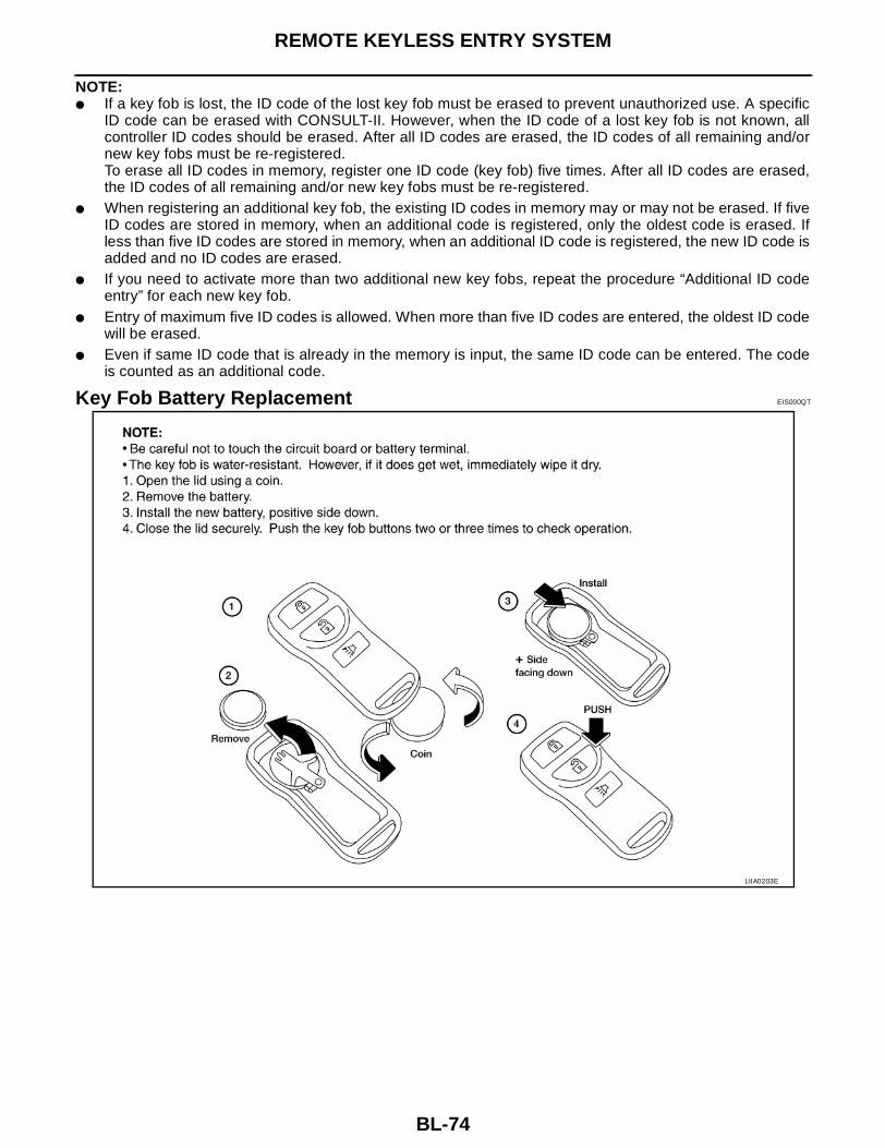
BL-74
REMOTE KEYLESS ENTRY SYSTEM
NOTE:● If a key fob is lost, the ID code of the lost key fob must be erased to prevent unauthorized use. A specific
ID code can be erased with CONSULT-II. However, when the ID code of a lost key fob is not known, allcontroller ID codes should be erased. After all ID codes are erased, the ID codes of all remaining and/ornew key fobs must be re-registered.To erase all ID codes in memory, register one ID code (key fob) five times. After all ID codes are erased,the ID codes of all remaining and/or new key fobs must be re-registered.
● When registering an additional key fob, the existing ID codes in memory may or may not be erased. If fiveID codes are stored in memory, when an additional code is registered, only the oldest code is erased. Ifless than five ID codes are stored in memory, when an additional ID code is registered, the new ID code isadded and no ID codes are erased.
● If you need to activate more than two additional new key fobs, repeat the procedure “Additional ID codeentry” for each new key fob.
● Entry of maximum five ID codes is allowed. When more than five ID codes are entered, the oldest ID codewill be erased.
● Even if same ID code that is already in the memory is input, the same ID code can be entered. The codeis counted as an additional code.
Key Fob Battery Replacement EIS000QT
LIIA0203E
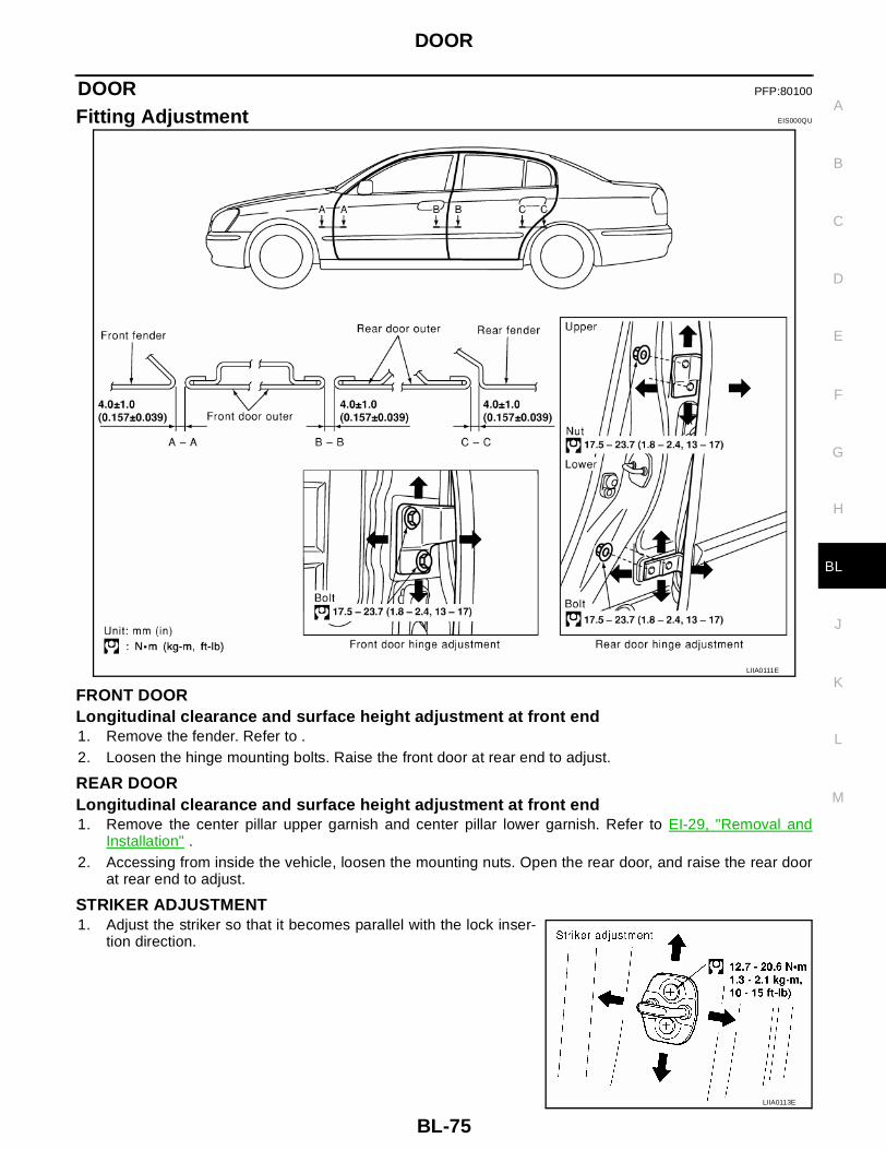
DOOR
BL-75
C
D
E
F
G
H
J
K
L
M
A
B
BL
DOOR PFP:80100
Fitting Adjustment EIS000QU
FRONT DOORLongitudinal clearance and surface height adjustment at front end1. Remove the fender. Refer to .2. Loosen the hinge mounting bolts. Raise the front door at rear end to adjust.
REAR DOORLongitudinal clearance and surface height adjustment at front end1. Remove the center pillar upper garnish and center pillar lower garnish. Refer to EI-29, "Removal and
Installation" .2. Accessing from inside the vehicle, loosen the mounting nuts. Open the rear door, and raise the rear door
at rear end to adjust.
STRIKER ADJUSTMENT1. Adjust the striker so that it becomes parallel with the lock inser-
tion direction.
LIIA0111E
LIIA0113E
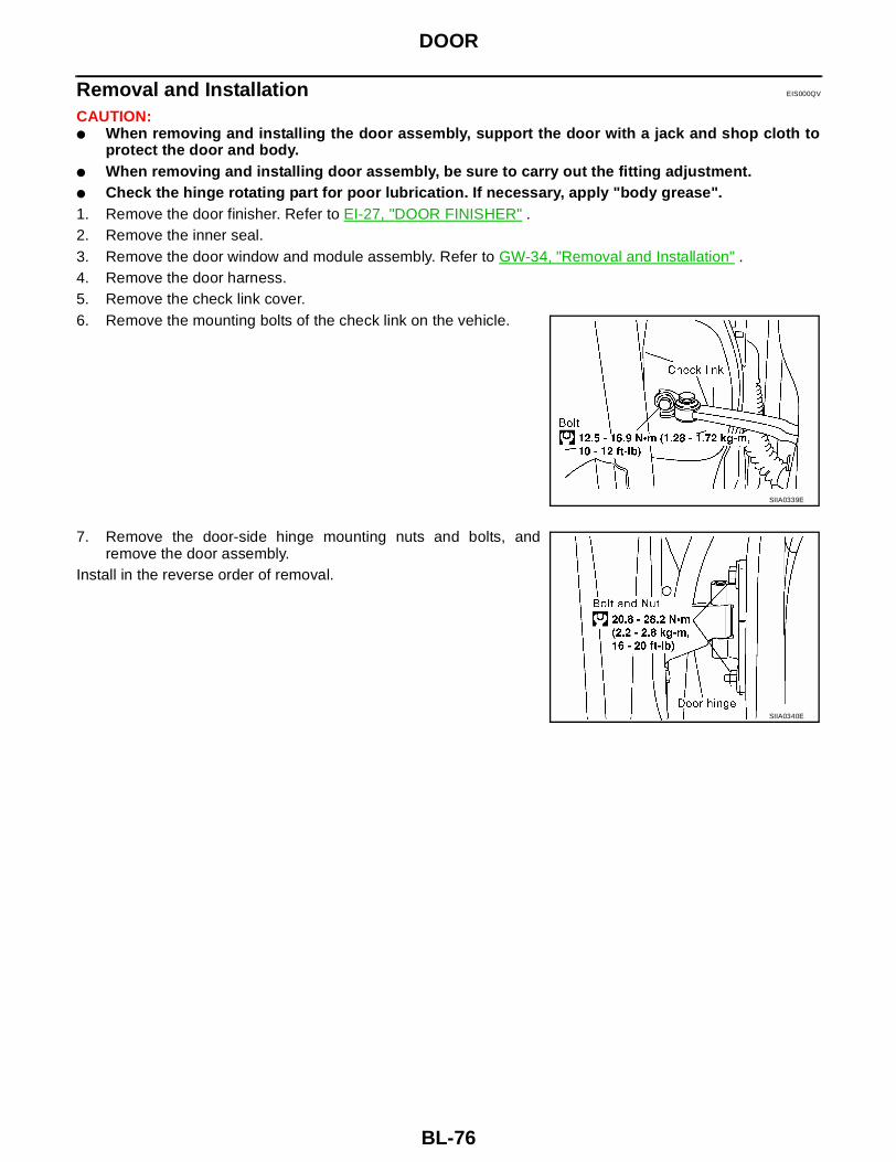
BL-76
DOOR
Removal and Installation EIS000QV
CAUTION:● When removing and installing the door assembly, support the door with a jack and shop cloth to
protect the door and body.● When removing and installing door assembly, be sure to carry out the fitting adjustment.● Check the hinge rotating part for poor lubrication. If necessary, apply "body grease".1. Remove the door finisher. Refer to EI-27, "DOOR FINISHER" .2. Remove the inner seal. 3. Remove the door window and module assembly. Refer to GW-34, "Removal and Installation" .4. Remove the door harness.5. Remove the check link cover.6. Remove the mounting bolts of the check link on the vehicle.
7. Remove the door-side hinge mounting nuts and bolts, andremove the door assembly.
Install in the reverse order of removal.
SIIA0339E
SIIA0340E

DOOR
BL-77
C
D
E
F
G
H
J
K
L
M
A
B
BL
Door Weatherstrip EIS000QW
LIIA0114E
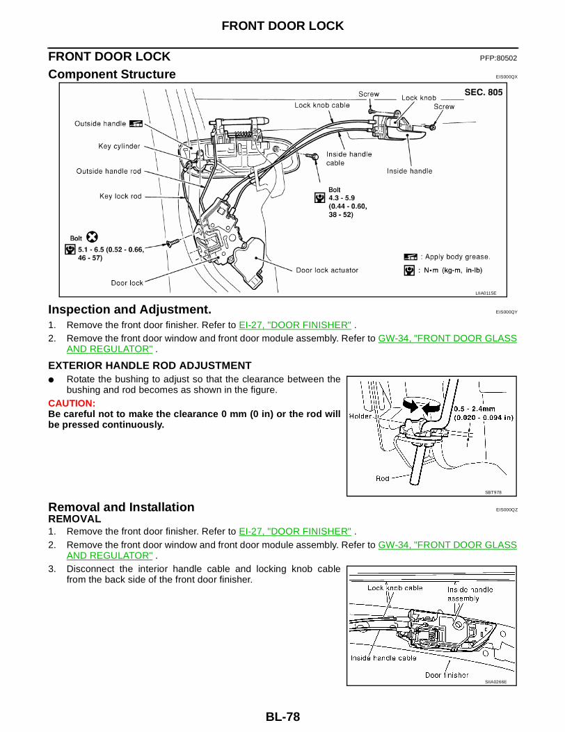
BL-78
FRONT DOOR LOCK
FRONT DOOR LOCK PFP:80502
Component Structure EIS000QX
Inspection and Adjustment. EIS000QY
1. Remove the front door finisher. Refer to EI-27, "DOOR FINISHER" .2. Remove the front door window and front door module assembly. Refer to GW-34, "FRONT DOOR GLASS
AND REGULATOR" .
EXTERIOR HANDLE ROD ADJUSTMENT● Rotate the bushing to adjust so that the clearance between the
bushing and rod becomes as shown in the figure.CAUTION:Be careful not to make the clearance 0 mm (0 in) or the rod willbe pressed continuously.
Removal and Installation EIS000QZ
REMOVAL1. Remove the front door finisher. Refer to EI-27, "DOOR FINISHER" .2. Remove the front door window and front door module assembly. Refer to GW-34, "FRONT DOOR GLASS
AND REGULATOR" .3. Disconnect the interior handle cable and locking knob cable
from the back side of the front door finisher.
LIIA0115E
SBT978
SIIA0266E

FRONT DOOR LOCK
BL-79
C
D
E
F
G
H
J
K
L
M
A
B
BL
4. Reach to separate the key cylinder rod and exterior handle rod connection (on the handle).5. Remove the mounting screws (TORX T30), remove the door
lock assembly.6. Disconnect the door lock actuator connector.
7. Remove the exterior handle mounting bolts, move the exteriorhandle assembly backward, and then remove it from the panelin front of the exterior handle escutcheon.
Install in the reverse order of removal.CAUTION:To install each rod, be sure to rotate the rod holder until a clickis felt.
Disassembly and Assembly EIS000R0
DISASSEMBLYCAUTION:Be sure to remove or install the actuator with the door lock assembly removed.1. Remove the mounting screws, and remove the actuator from the
door lock assembly.2. Pull the actuator straight downward to separate it from the door
lock assembly.
ASSEMBLY1. Align the actuator pivot with the cutout on the knob lever of the door lock assembly, then assemble the
actuator.2. Move the knob lever and the actuator pivot toward the lock-on direction, and check that it engages
securely.
LIIA0116E
SIIA0342E
SIIA0343E

BL-80
REAR DOOR LOCK
REAR DOOR LOCK PFP:82502
Components EIS000R1
Inspection and Adjustment EIS000R2
Remove the rear door finisher. Refer to EI-27, "DOOR FINISHER" .
EXTERIOR HANDLE ROD ADJUSTMENTRotate the bushing to adjust so that the clearance between the bush-ing and rod becomes as shown in the figure.CAUTION:Be careful not to make the clearance 0 mm (0 in) or the rod willbe pressed continuously.
Removal and Installation of Door Lock EIS000R3
REMOVAL1. Remove the rear door finisher. Refer to EI-27, "DOOR FINISHER"
LIIA0121E
SBT978

REAR DOOR LOCK
BL-81
C
D
E
F
G
H
J
K
L
M
A
B
BL
2. After gaining access to the interior handle on the back side ofthe rear door finisher, disconnect the interior handle cable andlocking knob cable.
3. Remove the mounting screws (TORX T30), remove the doorlock assembly.
4. Disconnect the door lock actuator connector.
5. Remove the exterior handle mounting bolts, and move the han-dle backward to disengage it from the panel in front of the exte-rior handle escutcheon, then remove the handle.
Install in the reverse order of removal.CAUTION:To install each rod, be sure to rotate the rod holder until a clickis felt.
Disassembly and Assembly EIS000R4
DISASSEMBLYCAUTION:Be sure to remove or install the actuator with the door lock assembly removed.1. Remove the mounting screws, and remove the actuator from the
door lock assembly.2. Pull the actuator straight downward to separate it from the door
lock assembly.
ASSEMBLY1. Align the actuator pivot with the cutout on the knob lever of the door lock assembly, then assemble the
actuator.2. Move the knob lever and the actuator pivot toward the lock-on direction, and check that it engages
securely.
SIIA0266E
LIIA0117E
SIIA0345E
SIIA0346E
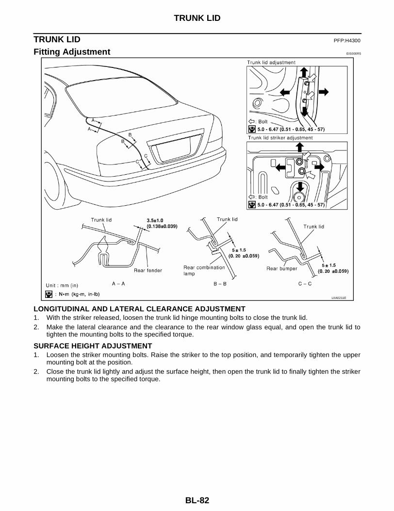
BL-82
TRUNK LID
TRUNK LID PFP:H4300
Fitting Adjustment EIS000R5
LONGITUDINAL AND LATERAL CLEARANCE ADJUSTMENT1. With the striker released, loosen the trunk lid hinge mounting bolts to close the trunk lid.2. Make the lateral clearance and the clearance to the rear window glass equal, and open the trunk lid to
tighten the mounting bolts to the specified torque.
SURFACE HEIGHT ADJUSTMENT1. Loosen the striker mounting bolts. Raise the striker to the top position, and temporarily tighten the upper
mounting bolt at the position.2. Close the trunk lid lightly and adjust the surface height, then open the trunk lid to finally tighten the striker
mounting bolts to the specified torque.
LIIA0211E

TRUNK LID
BL-83
C
D
E
F
G
H
J
K
L
M
A
B
BL
Removal and Installation of Trunk Lid Assembly EIS000R6
1. Remove the trunk lid finisher. Refer to EI-35, "TRUNK ROOM TRIM & TRUNK LID FINISHER" .2. Disconnect the connectors in the trunk lid, and remove the harness clamps to pull the harness out of the
trunk lid.3. Remove the mounting bolts, and remove the trunk lid assembly.
CAUTION:After installing, apply touch-up paint (the body color) onto the head of the hinge mounting bolts.
Install in the reverse order of removal.
Removal and Installation of Trunk Lid Lock EIS000R7
LOCK REMOVAL1. Remove the trunk lid finisher. Refer to EI-35, "TRUNK ROOM
TRIM & TRUNK LID FINISHER" .2. Separate the key cylinder rod.3. After removing the harness connector, remove the mounting
bolts, and remove the trunk lid lock.
STRIKER REMOVAL1. Remove the trunk rear plate and trunk rear finisher. Refer to EI-
35, "TRUNK ROOM TRIM & TRUNK LID FINISHER" .2. Remove the mounting bolts, and remove the trunk lock support
from the vehicle.3. After removing the harness connector, remove the mounting
bolts, and remove the striker from the trunk lock support.
LOCK AND STRIKER INSTALLATION1. Install in the reverse order of removal.
SIIA0330E
SIIA0331E
LIIA0212E
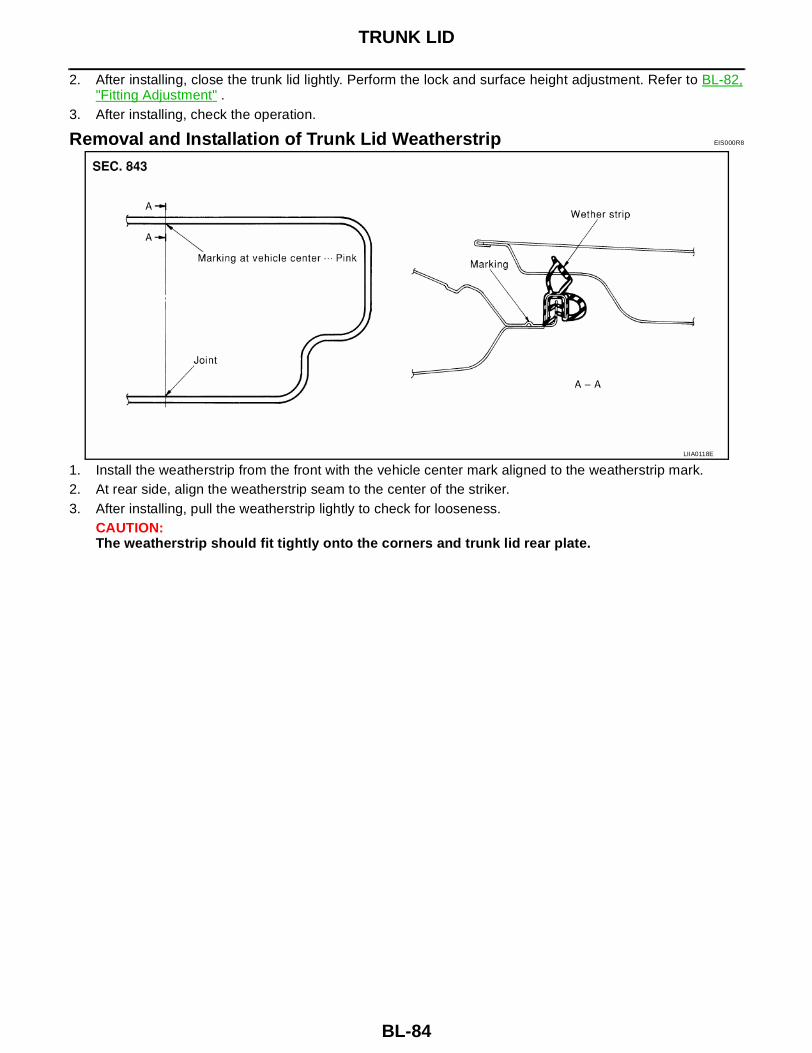
BL-84
TRUNK LID
2. After installing, close the trunk lid lightly. Perform the lock and surface height adjustment. Refer to BL-82,"Fitting Adjustment" .
3. After installing, check the operation.
Removal and Installation of Trunk Lid Weatherstrip EIS000R8
1. Install the weatherstrip from the front with the vehicle center mark aligned to the weatherstrip mark.2. At rear side, align the weatherstrip seam to the center of the striker.3. After installing, pull the weatherstrip lightly to check for looseness.
CAUTION:The weatherstrip should fit tightly onto the corners and trunk lid rear plate.
LIIA0118E

TRUNK LID OPENER
BL-85
C
D
E
F
G
H
J
K
L
M
A
B
BL
TRUNK LID OPENER PFP:84640
Wiring Diagram -TLID- EIS000R9
LIWA0029E
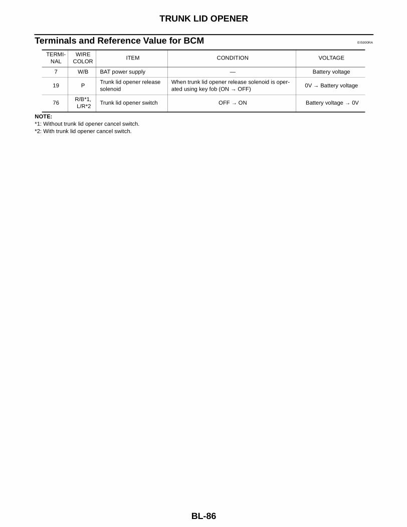
BL-86
TRUNK LID OPENER
Terminals and Reference Value for BCM EIS000RA
NOTE:*1: Without trunk lid opener cancel switch.*2: With trunk lid opener cancel switch.
TERMI-NAL
WIRE COLOR
ITEM CONDITION VOLTAGE
7 W/B BAT power supply — Battery voltage
19 PTrunk lid opener release solenoid
When trunk lid opener release solenoid is oper-ated using key fob (ON → OFF)
0V → Battery voltage
76R/B*1, L/R*2
Trunk lid opener switch OFF → ON Battery voltage → 0V

VEHICLE SECURITY (THEFT WARNING) SYSTEM
BL-87
C
D
E
F
G
H
J
K
L
M
A
B
BL
VEHICLE SECURITY (THEFT WARNING) SYSTEM PFP:28491
Component Parts and Harness Connector Location EIS000RB
LIIA0062E

BL-88
VEHICLE SECURITY (THEFT WARNING) SYSTEM
LIIA0063E

VEHICLE SECURITY (THEFT WARNING) SYSTEM
BL-89
C
D
E
F
G
H
J
K
L
M
A
B
BL
System Description EIS000RC
DESCRIPTIONSetting the vehicle security systemDisarmed phase● When the vehicle is being driven or when doors or trunk lid is open, the vehicle security system is set in
the disarmed phase on the assumption that the owner is inside or near the vehicle.Pre-armed phase and armed phase● The vehicle security system turns into the "pre-armed" phase when hood, trunk lid and all doors are
closed and locked by electronic key. The security indicator lamp illuminates for 30 seconds. then, the sys-tem automatically shifts into the "armed" phase.
Canceling the set vehicle security systemWhen one of the following operations is performed, the armed phase is canceled.1. Unlock the doors with the key or the key fob.2. Open the trunk lid with the key or the key fob. When the trunk lid is closed after opening the trunk lid with
the key fob, the system returns to the armed phase.
Activating the alarm operation of the vehicle security systemMake sure the system is in the armed phase.When one of the following operations is performed, the system sounds the horns and flashes the head-lampsfor about 50 seconds.1. Engine hood or any door is opened before unlocking door with key or key fob.2. Door is unlocked without using key or key fob.3. Trunk lid is opened without using key or key fob.
POWER SUPPLYPower is supplied at all times● through 10A fuse [No.19, located in the fuse block (J/B)]● to security indicator lamp terminal 1 and● to key switch and key lock solenoid terminal 3.Power is supplied at all times● through 50A fusible link (letter f, located in the fuse and fusible link box)● to BCM terminal 7.With the ignition switch in the ACC or ON position, power is supplied● through 10A fuse [No. 6, located in the fuse block (J/B)]● to BCM terminal 36.
INITIAL CONDITION TO ACTIVATE THE SYSTEMThe operation of the vehicle security system is controlled by the doors, hood and trunk lid.To activate the vehicle security system, BCM must receive signals indicating the doors, hood and trunk lid areclosed and the doors are locked.When a door is open, BCM terminal 10, 11 or 14 receives a ground signal from each door switch.When front door LH is unlocked, BCM terminal 74 receives a signal from terminal 14 of main power windowand door lock/unlock switch.When front door RH is unlocked, BCM terminal 74 receives a signal from terminal 11 of front power windowswitch RH.When the hood is open, IPDM E/R receives a ground signal● from hood switch terminal 2 ● to IPDM E/R terminal 51 ● through body grounds E15 and E24.The IPDM E/R then sends a signal to the BCM through the CAN SYSTEM.When the trunk lid is open, BCM terminal 18 receives a ground signal● from terminal 1 of the trunk lamp and trunk release solenoid switch● through body grounds B7 and B19.

BL-90
VEHICLE SECURITY (THEFT WARNING) SYSTEM
VEHICLE SECURITY SYSTEM ALARM OPERATIONThe vehicle security system is triggered by● opening a door● opening the trunk lid● opening the hood● unlocking door without using the key or key fob.The vehicle security system will be triggered once the system is in armed phase,● when BCM receives a ground signal at terminals 10, 11, 14 (door switch), 18 (trunk lamp and trunk
release solenoid switch) or receives a signal from the IPDM E/R (hood switch).Power is supplied at all times● to horn relay terminal 1● through 15A fuse (No. 25, located in fuse and fusible link box).When the vehicle security system is triggered, ground is supplied intermittently● from IPDM E/R terminal 53 ● to headlamp high relay and● to horn relay terminal 2.The headlamps flash and the horn sounds intermittently.The alarm automatically turns off after 50 seconds, but will reactivate if the vehicle is tampered with again.
VEHICLE SECURITY SYSTEM DEACTIVATIONTo deactivate the vehicle security system, a door or the trunk lid must be unlocked with the key or key fob.When the key is used to unlock a door, BCM terminal 74 receives signal● from terminal 14 of the main power window and door lock/unlock switch.When the key is used to unlock the trunk lid, BCM terminal 17 receives a ground signal from terminal 1 of thetrunk key cylinder switch (unlock switch).When the BCM receives either one of these signals or unlock signal from key fob, the vehicle security systemis deactivated. (Disarmed phase)
PANIC ALARM OPERATIONRemote keyless entry system may or may not operate vehicle security system (horn and headlamps) asrequired.When the remote keyless entry system is triggered, ground is supplied intermittently● from IPDM E/R terminal 53 ● to headlamp high relay and● to horn relay terminal 2.The headlamp flashes and the horn sounds intermittently.The alarm automatically turns off after 30 seconds or when BCM receives any signal from key fob.
CAN Communication System Description EIS000RD
CAN (Controller Area Network) is a serial communication line for real time application. It is an on-vehicle mul-tiplex communication line with high data communication speed and excellent error detection ability. Many elec-tronic control units are equipped onto a vehicle, and each control unit shares information and links with othercontrol units during operation (not independent). In CAN communication, control units are connected with 2communication lines (CAN H line, CAN L line) allowing a high rate of information transmission with less wiring.Each control unit transmits/receives data but selectively reads required data only.

VEHICLE SECURITY (THEFT WARNING) SYSTEM
BL-91
C
D
E
F
G
H
J
K
L
M
A
B
BL
FOR TCS MODELSSystem diagram
Input/output signal chartT: Transmit R: Receive
LKIA0015E
Signals ECM TCMCOMBINA-
TION METER
BCMABS/TCS
control unitIPDM E/R
Engine speed signal T R R
Engine coolant temperature signal T R
Accelerator pedal position signal T
Fuel consumption monitor signal T R
A/T warning lamp signal T R
A/T position indicator signal R T R R(R range only) R
ABS operation signal R T
TCS operation signal R R T
Air conditioner switch signal R T
Air conditioner compressor signal R T
A/C compressor request signal T R
Cooling fan motor operation signal R T
Cooling fan speed request signal T R
Position lights request R T R
Position lights status R T
Low beam request T R
Low beam status R R T
High beam request R T R
High beam status R R T
Front fog lights request T R
Front fog light status R T
OD cancel switch signal R T R
Brake switch signal R T
Vehicle speed signalR T
R T R
Oil pressure switch R T
Sleep request1 R T
Sleep request2 T R
N range switch signal R T
P range switch signal R T
Seat belt buckle switch signal T R

BL-92
VEHICLE SECURITY (THEFT WARNING) SYSTEM
FOR A/T MODELSSystem diagram
Input/output signal chartT: Transmit R: Receive
Door switch signal R T R
Tail lamp request R T R
Turn indicator signal R T
Buzzer output signal R T
Trunk switch signal R T
ASCD main switch signal T R
ASCD cruise signal T R
Wiper operation R T
Wiper stop position signal R T
Rear window defogger switch signal T R
Rear window defogger control sig-nal
R R T
Signals ECM TCMCOMBINA-
TION METER
BCMABS/TCS
control unitIPDM E/R
LKIA0017E
Signals ECM TCMCOMBINATION
METERBCM IPDM E/R
Engine speed signal T R
Engine coolant temperature signal T R
Accelerator pedal position signal T R
Fuel consumption monitor signal T R
A/T warning lamp signal T R
A/T position indicator signal R T R R(R range only)
Air conditioner switch signal R T
Air conditioner compressor signal R T
A/C compressor request signal T R
Blower fan switch signal R(QR25DE) T
Cooling fan motor operation signal R T
Cooling fan speed request signal T R
Position lights request R T R
Position lights status R T
Low beam request T R
Low beam status R R T
High beam request R T R

VEHICLE SECURITY (THEFT WARNING) SYSTEM
BL-93
C
D
E
F
G
H
J
K
L
M
A
B
BL
FOR M/T MODELSSystem diagram
Input/output signal chartT: Transmit R: Receive
High beam status R R T
Front fog lights request T R
Front fog light status R T
OD cancel switch signal R T R
Brake switch signal R T
Vehicle speed signalR T
R T R
Oil pressure switch R T
Sleep request1 R T
Sleep request2 T R
N range switch signal R T
P range switch signal R T
Seat belt buckle switch signal T R
Door switch signal R T R
Tail lamp request R T R
Turn indicator signal R T
Buzzer output signal R T
Trunk switch signal R T
ASCD main switch signal T R
ASCD cruise signal T R
Wiper operation R T
Wiper stop position signal R T
Rear window defogger switch signal T R
Rear window defogger control signal R R T
Signals ECM TCMCOMBINATION
METERBCM IPDM E/R
LKIA0018E
Signals ECMCOMBINATION
METERBCM IPDM E/R
Engine speed signal T
Engine coolant temperature signal T
Fuel consumption monitor signal T
Air conditioner switch signal R T
Air conditioner compressor signal R T
A/C compressor request signal T R

BL-94
VEHICLE SECURITY (THEFT WARNING) SYSTEM
Blower fan switch signal R(QR25DE) T
Cooling fan motor operation signal R T
Cooling fan speed request signal T R
Position lights request R T R
Position lights status R T
Low beam request T R
Low beam status R R T
High beam request R T R
High beam status R R T
Front fog lights request T R
Front fog light status R T
Vehicle speed signal R T
Oil pressure switch R T
Sleep request1 R T
Sleep request2 T R
Seat belt buckle switch signal T R
Door switch signal R T R
Tail lamp request R T R
Turn indicator signal R T
Buzzer output signal R T
Trunk switch signal R T
ASCD main switch signal T R
ASCD cruise signal T R
Wiper operation R T
Wiper stop position signal R T
Rear window defogger switch signal T R
Rear window defogger control signal R R T
Signals ECMCOMBINATION
METERBCM IPDM E/R
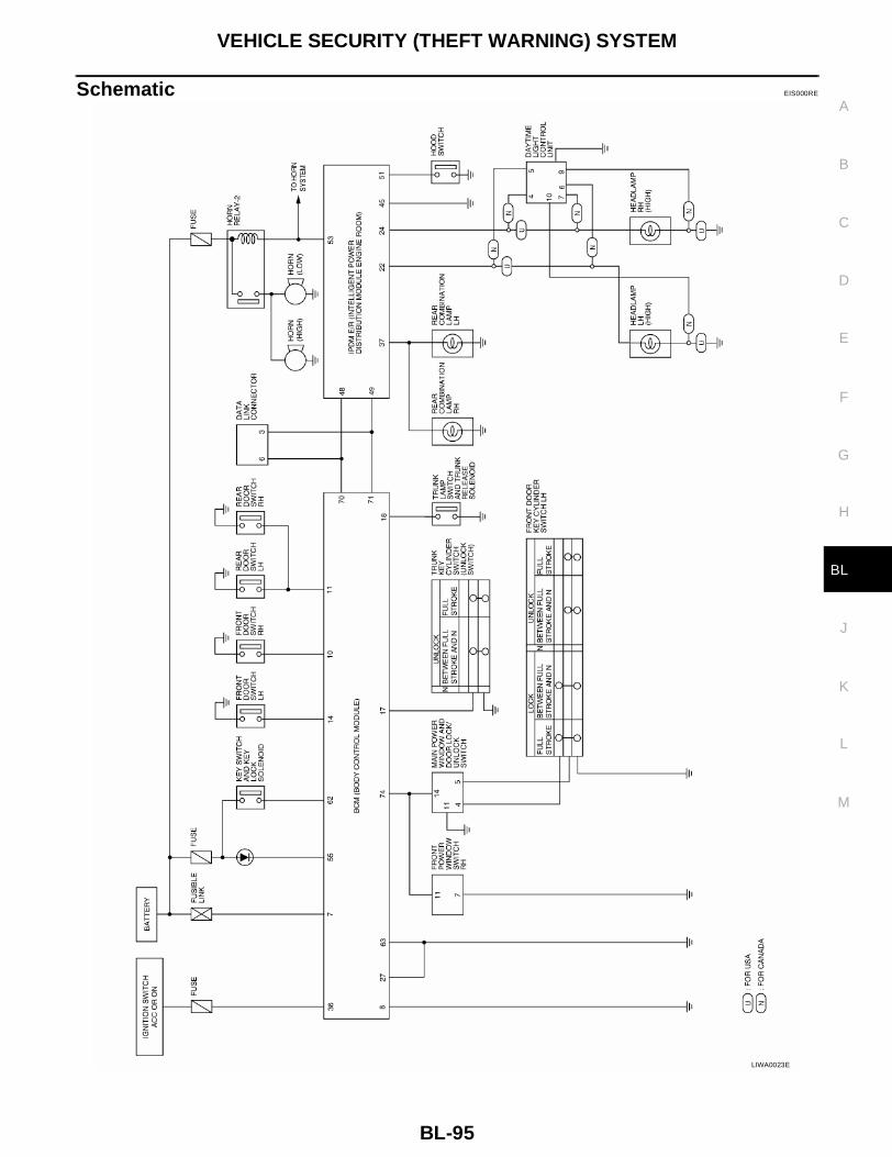
VEHICLE SECURITY (THEFT WARNING) SYSTEM
BL-95
C
D
E
F
G
H
J
K
L
M
A
B
BL
Schematic EIS000RE
LIWA0023E
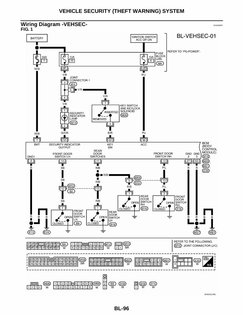
BL-96
VEHICLE SECURITY (THEFT WARNING) SYSTEM
Wiring Diagram -VEHSEC- EIS000RF
FIG. 1
WIWA0146E

VEHICLE SECURITY (THEFT WARNING) SYSTEM
BL-97
C
D
E
F
G
H
J
K
L
M
A
B
BL
FIG. 2
LIWA0025E

BL-98
VEHICLE SECURITY (THEFT WARNING) SYSTEM
FIG. 3
LIWA0026E

VEHICLE SECURITY (THEFT WARNING) SYSTEM
BL-99
C
D
E
F
G
H
J
K
L
M
A
B
BL
FIG. 4
LIWA0027E

BL-100
VEHICLE SECURITY (THEFT WARNING) SYSTEM
FIG. 5
LIWA0028E

VEHICLE SECURITY (THEFT WARNING) SYSTEM
BL-101
C
D
E
F
G
H
J
K
L
M
A
B
BL
CONSULT-II Function EIS000RG
CONSULT-II INSPECTION PROCEDURE1. With the ignition switch OFF, connect CONSULT-II to the data
link connector, and turn the ignition switch ON.
2. Touch "START".
3. Touch "BCM" on the "SELECT SYSTEM" screen.
4. Touch "THEFT ALM" on the "SELECT TEST ITEM" screen.● WORK SUPPORT, DATA MONITOR and ACTIVE TEST are
available for the vehicle security system.
CONSULT-II APPLICATION ITEMData Monitor
BBIA0002E
PIIA0182E
LIIA0033E
LIIA0034E
Monitored Item Description
IGN ON SW Indicates [ON/OFF] condition of ignition switch.
ACC ON SW Indicates [ON/OFF] condition of ignition switch in ACC position.
KEY CYL LK SW Indicates [ON/OFF] condition of lock signal from key cylinder switch.
KEY CYL UN SW Indicates [ON/OFF] condition of unlock signal from key cylinder switch.

BL-102
VEHICLE SECURITY (THEFT WARNING) SYSTEM
Active Test
Work Support
DOOR SW-DR Indicates [ON/OFF] condition of front door switch LH.
DOOR SW-AS Indicates [ON/OFF] condition of front door switch RH.
DOOR SW-RR Indicates [ON/OFF] condition of rear door switches.
TRNK OPN MTR Indicates [ON/OFF] condition of trunk opener motor.
TRNK OPNR SW Indicates [ON/OFF] condition of trunk opener switch.
TRUNK KEY SW Indicates [ON/OFF] condition of trunk key cylinder switch.
HOOD SWITCH Indicates [ON/OFF] condition of hood switch.
LOCK SW DR/AS Indicates [ON/OFF] condition of lock signal from door lock/unlock switch LH and RH.
UNLK SW DR/AS Indicates [ON/OFF] condition of unlock signal from door lock/unlock switch LH and RH.
LK BUTTON/SIG Indicates [ON/OFF] condition of lock signal from key fob.
UN BUTTON/SIG Indicates [ON/OFF] condition of unlock signal from key fob.
TRUNK BTN/SIG Indicates [ON/OFF] condition of trunk open signal from key fob.
Monitored Item Description
Test Item Description
THEFT INDThis test is able to check security indicator lamp operation. The lamp will be turned on when “ON” on CONSULT-II screen is touched.
HEADLAMPThis test is able to check vehicle security lamp operation. The headlamps will be activated for 0.5 seconds after “ON” on CONSULT-II screen is touched.
HORNThis test is able to check vehicle security horn operation. The horns will be activated for 0.5 sec-onds after “ON” on CONSULT-II screen is touched.
Test Item Description
SECURITY ALARM SET .
THEFT ALM TRGThe switch which triggered vehicle security alarm is recorded. This mode is able to confirm and erase the record of vehicle security alarm. The trigger data can be erased by touching “CLEAR” on CONSULT-II screen.

VEHICLE SECURITY (THEFT WARNING) SYSTEM
BL-103
C
D
E
F
G
H
J
K
L
M
A
B
BL
Trouble Diagnosis EIS000RH
WORK FLOW
● “POWER DOOR LOCK SYSTEM” Diagnosis refer to BL-16, "POWER DOOR LOCK SYSTEM" .● “REMOTE CONTROL SYSTEM” Diagnosis refer to BL-43, "REMOTE KEYLESS ENTRY SYSTEM" .
LIIA0123E
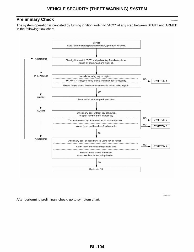
BL-104
VEHICLE SECURITY (THEFT WARNING) SYSTEM
Preliminary Check EIS000RI
The system operation is canceled by turning ignition switch to "ACC" at any step between START and ARMEDin the following flow chart.
After performing preliminary check, go to symptom chart.LIIA0124E
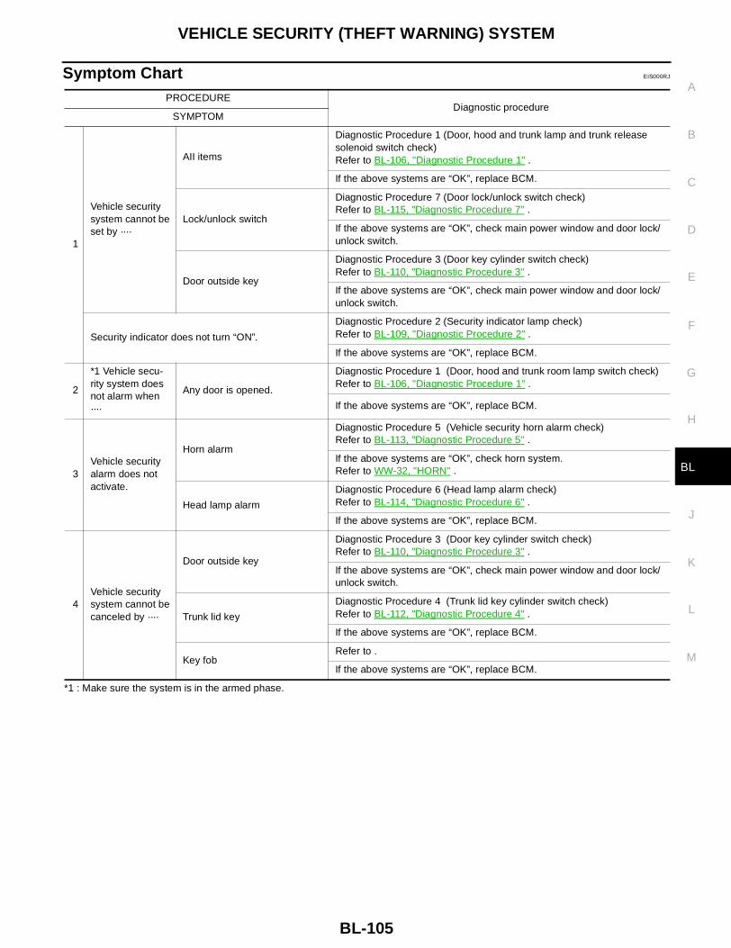
VEHICLE SECURITY (THEFT WARNING) SYSTEM
BL-105
C
D
E
F
G
H
J
K
L
M
A
B
BL
Symptom Chart EIS000RJ
*1 : Make sure the system is in the armed phase.
PROCEDUREDiagnostic procedure
SYMPTOM
1
Vehicle security system cannot be set by ····
AII items
Diagnostic Procedure 1 (Door, hood and trunk lamp and trunk release solenoid switch check)Refer to BL-106, "Diagnostic Procedure 1" .
If the above systems are “OK”, replace BCM.
Lock/unlock switch
Diagnostic Procedure 7 (Door lock/unlock switch check)Refer to BL-115, "Diagnostic Procedure 7" .
If the above systems are “OK”, check main power window and door lock/unlock switch.
Door outside key
Diagnostic Procedure 3 (Door key cylinder switch check)Refer to BL-110, "Diagnostic Procedure 3" .
If the above systems are “OK”, check main power window and door lock/unlock switch.
Security indicator does not turn “ON”.
Diagnostic Procedure 2 (Security indicator lamp check)Refer to BL-109, "Diagnostic Procedure 2" .
If the above systems are “OK”, replace BCM.
2
*1 Vehicle secu-rity system does not alarm when ····
Any door is opened.
Diagnostic Procedure 1 (Door, hood and trunk room lamp switch check)Refer to BL-106, "Diagnostic Procedure 1" .
If the above systems are “OK”, replace BCM.
3Vehicle security alarm does not activate.
Horn alarm
Diagnostic Procedure 5 (Vehicle security horn alarm check)Refer to BL-113, "Diagnostic Procedure 5" .
If the above systems are “OK”, check horn system. Refer to WW-32, "HORN" .
Head lamp alarm
Diagnostic Procedure 6 (Head lamp alarm check)Refer to BL-114, "Diagnostic Procedure 6" .
If the above systems are “OK”, replace BCM.
4Vehicle security system cannot be canceled by ····
Door outside key
Diagnostic Procedure 3 (Door key cylinder switch check)Refer to BL-110, "Diagnostic Procedure 3" .
If the above systems are “OK”, check main power window and door lock/unlock switch.
Trunk lid key
Diagnostic Procedure 4 (Trunk lid key cylinder switch check)Refer to BL-112, "Diagnostic Procedure 4" .
If the above systems are “OK”, replace BCM.
Key fobRefer to .
If the above systems are “OK”, replace BCM.
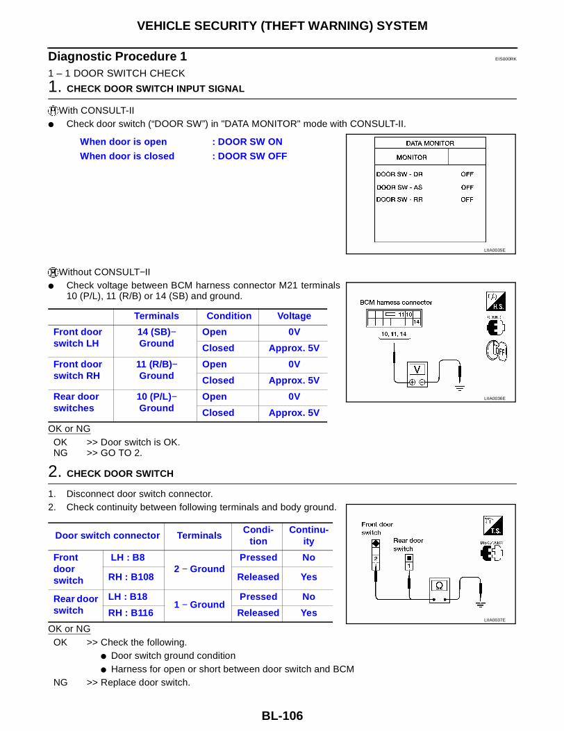
BL-106
VEHICLE SECURITY (THEFT WARNING) SYSTEM
Diagnostic Procedure 1 EIS000RK
1 – 1 DOOR SWITCH CHECK
1. CHECK DOOR SWITCH INPUT SIGNAL
With CONSULT-II● Check door switch (“DOOR SW”) in "DATA MONITOR" mode with CONSULT-II.
Without CONSULT−II● Check voltage between BCM harness connector M21 terminals
10 (P/L), 11 (R/B) or 14 (SB) and ground.
OK or NGOK >> Door switch is OK.NG >> GO TO 2.
2. CHECK DOOR SWITCH
1. Disconnect door switch connector.2. Check continuity between following terminals and body ground.
OK or NGOK >> Check the following.
● Door switch ground condition● Harness for open or short between door switch and BCM
NG >> Replace door switch.
When door is open : DOOR SW ON
When door is closed : DOOR SW OFF
LIIA0035E
Terminals Condition Voltage
Front door switch LH
14 (SB)− Ground
Open 0V
Closed Approx. 5V
Front door switch RH
11 (R/B)− Ground
Open 0V
Closed Approx. 5V
Rear door switches
10 (P/L)− Ground
Open 0V
Closed Approx. 5V
LIIA0036E
Door switch connector TerminalsCondi-
tionContinu-
ity
Front door switch
LH : B82 − Ground
Pressed No
RH : B108 Released Yes
Rear door switch
LH : B181 − Ground
Pressed No
RH : B116 Released YesLIIA0037E

VEHICLE SECURITY (THEFT WARNING) SYSTEM
BL-107
C
D
E
F
G
H
J
K
L
M
A
B
BL
1 – 2 HOOD SWITCH CHECK
1. CHECK HOOD SWITCH
Check hood switch and hood fitting condition.OK or NGOK >> GO TO 2.NG >> Adjust installation of hood switch.
2. CHECK HOOD SWITCH INPUT SIGNAL
With CONSULT-II● Check “HOOD SW” in "DATA MONITOR" mode with CONSULT-
II.
Without CONSULT-II● Check voltage between IPDM E/R harness connector E121 ter-
minal 51 (Y/B) and ground.Refer to BL-99, "FIG. 4" .
OK or NGOK >> Hood switch is OK.NG >> GO TO 3.
3. CHECK HOOD SWITCH
1. Disconnect hood switch connector.2. Check continuity between hood switch connector E5 terminals 1 and 2.
OK or NGOK >> Check the following.
● Hood switch ground circuit● Harness for open or short between hood switch and
IPDM E/RNG >> Replace hood switch.
When hood is open : HOOD SW ON
When hood is closed : HOOD SW OFF
LIIA0038E
LIIA0039E
Terminals Condition Continuity
1 − 2Pressed No
Released Yes
LIIA0040E

BL-108
VEHICLE SECURITY (THEFT WARNING) SYSTEM
1 – 3 TRUNK LAMP AND TRUNK RELEASE SOLENOID SWITCH CHECK
1. CHECK TRUNK LAMP SWITCH AND TRUNK RELEASE SOLENOID INPUT SIGNAL
With CONSULT-II● Check “TRUNK SW” in "DATA MONITOR" mode with CONSULT-II.
Without CONSULT-II● Check voltage between BCM harness connector M21 terminal
18 (PU/W) and ground.Refer to BL-97, "FIG. 2" .
OK or NGOK >> Trunk room lamp and trunk release solenoid switch is
OK.NG >> GO TO 2.
2. CHECK TRUNK LAMP AND TRUNK RELEASE SOLENOID SWITCH
1. Disconnect trunk lamp and trunk release solenoid switch connector.2. Check continuity between trunk lamp and trunk release solenoid switch connector B32 terminals 1 and 2.
OK or NGOK >> Check the following.
● Trunk lamp and trunk release solenoid switch groundcircuit
● Harness for open or short between trunk lamp andtrunk release solenoid switch and BCM
NG >> Replace trunk lamp and trunk release solenoid switch.
When trunk lid is open : TRNK OPN MNTR ON
When trunk lid is closed : TRNK OPN MNTR OFF
WIIA0108E
LIIA0042E
Connector Terminals Condition Continuity
B32 1 − 2Closed No
Open Yes
LIIA0043E

VEHICLE SECURITY (THEFT WARNING) SYSTEM
BL-109
C
D
E
F
G
H
J
K
L
M
A
B
BL
Diagnostic Procedure 2 EIS000RL
SECURITY INDICATOR LAMP CHECK
1. SECURITY INDICATOR LAMP ACTIVE TEST
With CONSULT-II● Check "THEFT IND” in "ACTIVE TEST" mode with CONSULT-II.
Without CONSULT-II1. Disconnect BCM harness connector M18.2. Check voltage between BCM harness connector M18 terminal
55 (G/OR) and ground.
OK or NGOK >> Security indicator lamp is OK.NG >> GO TO 2.
2. SECURITY INDICATOR LAMP CHECK
Check indicator lamp condition.Refer to BL-96, "FIG. 1" .OK or NGOK >> GO TO 3.NG >> Replace indicator lamp.
3. CHECK POWER SUPPLY CIRCUIT FOR SECURITY INDICATOR LAMP
1. Disconnect security indicator lamp connector.2. Check voltage between security indicator lamp harness connector M14 terminal 1 (Y/R) and ground.
OK or NGOK >> Check harness for open or short between security indi-
cator lamp and BCM.NG >> Check the following.
● 10A fuse [No. 19, located in fuse block (J/B)]● Harness for open or short between security indicator
lamp and fuse
LIIA0044E
Battery voltage should exist.
LIIA0045E
Battery voltage should exist.
LIIA0046E

BL-110
VEHICLE SECURITY (THEFT WARNING) SYSTEM
Diagnostic Procedure 3 EIS000RM
3–1 DOOR KEY CYLINDER LOCK SWITCH CHECK
1. CHECK FRONT DOOR KEY CYLINDER SWITCH LH INPUT SIGNAL (LOCK SIGNAL)
With CONSULT-II● Check front door key cylinder switch LH (“KEY CYL LK SW”) in "DATA MONITOR" mode with CONSULT-
II.
Without CONSULT-IICheck voltage between main power window and door lock/unlockswitch harness connector D7 terminal 4 (P/L) and ground.
OK or NGOK >> Front door key cylinder switch LH (lock) is OK.NG >> GO TO 2.
2. CHECK FRONT DOOR KEY CYLINDER SWITCH LH
1. Disconnect front door key cylinder switch LH connector.2. Check continuity between front door key cylinder switch LH connector D50 terminals 2 (Y) and 3 (B).
OK or NGOK >> Check the following.
● Front door key cylinder switch LH ground circuit● Harness for open or short between main power win-
dow and door lock/unlock switch and front door keycylinder switch LH
NG >> Replace front door key cylinder switch LH.
“KEY CYL LK SW” should be “ON” when key inserted in door key cylinder was turned to lock.
LIIA0047E
Key position Voltage
Neutral / Unlock Approx. 5V
Lock 0V
LIIA0048E
Key position Continuity
Neutral / Unlock No
Lock Yes
LIIA0049E

VEHICLE SECURITY (THEFT WARNING) SYSTEM
BL-111
C
D
E
F
G
H
J
K
L
M
A
B
BL
3–2 DOOR KEY CYLINDER UNLOCK SWITCH CHECK
1. CHECK FRONT DOOR KEY CYLINDER SWITCH LH INPUT SIGNAL (UNLOCK SIGNAL)
With CONSULT-II● Check front door key cylinder switch LH (“KEY CYL UN SW”) in "DATA MONITOR" mode with CONSULT-
II.
Without CONSULT-IICheck voltage between main power window and door lock/unlockswitch harness connector D7 terminal 5 (W/L) and ground.
OK or NGOK >> Front door key cylinder switch LH (unlock) is OK.NG >> GO TO 2.
2. CHECK FRONT DOOR KEY CYLINDER SWITCH LH
1. Disconnect front door key cylinder switch LH connector.2. Check continuity between front door key cylinder switch LH con-
nector D50 terminals 1 (L) and 3 (B).
OK or NGOK >> Check the following.
● Front door key cylinder switch LH ground circuit● Harness for open or short between main power win-
dow and door lock/unlock switch and front door key cylinder switch LHNG >> Replace front door key cylinder switch LH.
“KEY CYL UN SW” should be “ON” when key inserted in door key cylinder was turned to unlock.
LIIA0050E
Key position Voltage
Neutral / Lock Approx. 5V
Unlock 0V
LIIA0051E
Key position Continuity
Neutral / Lock No
Unlock Yes
LIIA0052E

BL-112
VEHICLE SECURITY (THEFT WARNING) SYSTEM
Diagnostic Procedure 4 EIS000RN
TRUNK LID KEY UNLOCK SIGNAL CHECK
1. CHECK TRUNK KEY CYLINDER SWITCH INPUT SIGNAL (UNLOCK SIGNAL)
With CONSULT-IICheck trunk key cylinder switch (“TRUNK KEY SW”) in "DATA MONITOR" mode with CONSULT-II.● When key in key cylinder is at “NEUTRAL” position,
● When key is at “UNLOCK” position,
Without CONSULT-II● Check voltage between BCM harness connector M21 terminal
17 (L/B) and ground.
OK or NGOK >> Trunk key cylinder switch is OK.NG >> GO TO 2.
2. CHECK TRUNK KEY CYLINDER SWITCH (UNLOCK SWITCH)
1. Disconnect trunk key cylinder switch connector.2. Check continuity between trunk key cylinder switch connector B34 terminals 1 and 2.
OK or NGOK >> Check the following.
● Trunk key cylinder switch ground circuit● Harness for open or short between trunk key cylinder
switch and BCMNG >> Replace trunk key cylinder switch.
TRUNK KEY SW : OFF
TRUNK KEY SW : ON
WIIA0109E
Condition Voltage
Neutral Approx. 5V
Unlocked 0V
LIIA0054E
Condition Continuity
Neutral No
Unlocked Yes
LIIA0055E

VEHICLE SECURITY (THEFT WARNING) SYSTEM
BL-113
C
D
E
F
G
H
J
K
L
M
A
B
BL
Diagnostic Procedure 5 EIS000RO
VEHICLE SECURITY HORN ALARM CHECK
1. CHECK VEHICLE SECURITY HORN ALARM OPERATION
With CONSULT-II● Check horn relay “HORN” in "ACTIVE TEST" mode with CONSULT-II.● Perform operation shown on display.
Without CONSULT-II1. Disconnect IPDM E/R connector E121.2. Apply ground to IPDM E/R harness connector E121 terminal 53 (G/W).
OK or NGOK >> Horn alarm is OK.NG >> GO TO 2.
2. CHECK HORN RELAY
Check horn relay condition.OK or NGOK >> GO TO 3.NG >> Replace horn relay.
3. CHECK POWER SUPPLY FOR HORN RELAY
1. Disconnect horn relay connector.2. Check voltage between horn relay connector H-1 terminal 1 and ground.
OK or NGOK >> GO TO 4.NG >> Check the following.
● 15A fuse (No. 25, located in the fuse and fusible linkbox)
● Harness for open or short between horn relay andfuse
Vehicle security horn alarm should operate.
LIIA0056E
Does horn alarm activate?
LIIA0057E
Battery voltage should exist.
LIIA0058E
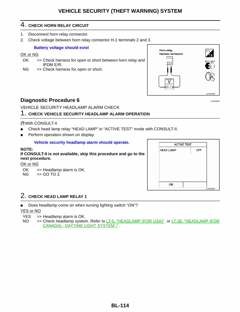
BL-114
VEHICLE SECURITY (THEFT WARNING) SYSTEM
4. CHECK HORN RELAY CIRCUIT
1. Disconnect horn relay connector.2. Check voltage between horn relay connector H-1 terminals 2 and 3.
OK or NGOK >> Check harness for open or short between horn relay and
IPDM E/R.NG >> Check harness for open or short.
Diagnostic Procedure 6 EIS000RP
VEHICLE SECURITY HEADLAMP ALARM CHECK
1. CHECK VEHICLE SECURITY HEADLAMP ALARM OPERATION
With CONSULT-II● Check head lamp relay “HEAD LAMP” in "ACTIVE TEST" mode with CONSULT-II.● Perform operation shown on display.
NOTE:If CONSULT-II is not available, skip this procedure and go to thenext procedure.OK or NG
OK >> Headlamp alarm is OK.NG >> GO TO 2.
2. CHECK HEAD LAMP RELAY 1
● Does headlamp come on when turning lighting switch “ON”?YES or NO
YES >> Headlamp alarm is OK.NO >> Check headlamp system. Refer to LT-5, "HEADLAMP (FOR USA)" or LT-28, "HEADLAMP (FOR
CANADA) - DAYTIME LIGHT SYSTEM -" .
Battery voltage should exist
LIIA0059E
Vehicle security headlamp alarm should operate.
LIIA0060E

VEHICLE SECURITY (THEFT WARNING) SYSTEM
BL-115
C
D
E
F
G
H
J
K
L
M
A
B
BL
Diagnostic Procedure 7 EIS000RQ
DOOR LOCK/UNLOCK SWITCH CHECK
1. CHECK DOOR LOCK/UNLOCK SWITCH INPUT SIGNAL
With CONSULT-IICheck door lock/unlock switch (“LOCK SW DR/AS"/"UNLK SW DR/AS” in "DATA MONITOR" mode with CONSULT-II.● When lock/unlock switch is turned to LOCK:
● When lock/unlock switch is turned to UNLOCK:
Without CONSULT-IIDo doors lock/unlock when using main power window and door lock/unlock switch or front power windowswitch RH?YES or NO?YES >> Door lock/unlock switch is OK.NO >> Refer to BL-33, "Door Lock/Unlock Switch Check (With left and right front power window anti–
pinch system)" .
LOCK SW DR/AS ON
UNLK SW DR/AS ON
LIIA0061E

BL-116
NVIS(NISSAN VEHICLE IMMOBILIZER SYSTEM-NATS)
NVIS(NISSAN VEHICLE IMMOBILIZER SYSTEM-NATS) PFP:28591
Component Parts and Harness Connector Location EIS000RR
LIIA0150E

NVIS(NISSAN VEHICLE IMMOBILIZER SYSTEM-NATS)
BL-117
C
D
E
F
G
H
J
K
L
M
A
B
BL
System Description EIS000RS
NVIS (Nissan Vehicle Immobilizer System—NATS) has the following immobilizer functions:● Since only NVIS (NATS) ignition keys, whose ID nos. have been registered into the ECM and IMMU of
NVIS (NATS), allow the engine to run, operation of a stolen vehicle without a NVIS (NATS) registered keyis prevented by NVIS (NATS). NVIS (NATS) will immobilize the engine if someone tries to start it withoutthe registered key of NVIS (NATS).
● All of the originally supplied ignition key IDs have been NVIS (NATS) registered.If requested by the vehicle owner, a maximum of five key IDs can be registered into the NVIS (NATS)components.
● The security indicator lamp blinks when the ignition switch is in “OFF” or “ACC” position. Therefore, NVIS(NATS) warns outsiders that the vehicle is equipped with the system.
● When NVIS (NATS) detects trouble, the security indicator lamp lights up while ignition key is in the “ON”position.
● NVIS (NATS) trouble diagnoses, system initialization and additional registration for other NVIS (NATS)ignition key IDs must be carried out using CONSULT-II hardware and CONSULT-II NVIS (NATS) software.Regarding the procedures for NVIS (NATS) initialization and NVIS (NATS) ignition key ID registration,refer to CONSULT-II OPERATION MANUAL IVIS/NVIS.
● When servicing a malfunction of the NVIS (indicated by lighting up of Security Indicator Lamp) orregistering another NVIS ignition key ID no., it is necessary to re-register original key identifica-tion.
Therefore, be sure to receive ALL KEYS from vehicle owner.
System Composition EIS000RT
The immobilizer function of the NVIS (NATS) consists of the following:● NVIS (NATS) ignition key● NVIS (NATS) immobilizer control unit (IMMU) located around the ignition key cylinder● ECM● Security indicator lamp
WEL122A

BL-118
NVIS(NISSAN VEHICLE IMMOBILIZER SYSTEM-NATS)
Wiring Diagram — NATS — EIS000RU
LIWA0022E

NVIS(NISSAN VEHICLE IMMOBILIZER SYSTEM-NATS)
BL-119
C
D
E
F
G
H
J
K
L
M
A
B
BL
NVIS (NATS) IMMU CONTROL UNIT TERMINALS AND REFERENCE VALUE MEASURED BETWEEN EACH TERMINAL ANDGROUND
CONSULT-II EIS000RV
CONSULT-II INSPECTION PROCEDURE1. Turn ignition switch OFF.2. Connect CONSULT-II to data link connector.
3. Insert NVIS (NATS) program card into CONSULT-II.
4. Turn ignition switch ON.5. Touch “START”.6. Select “NATS V.5.0”.
TERMINAL WIRE COLOR ITEM CONDITION DATA (DC)
4 B GROUND — —
5 G/ORVEHICLE SECURITY INDICA-TOR
GOES OFF BATTERY VOLTAGE
ILLUMINATES APPROX. 0V
7 R
IGNITION SWITCH (ON)IGNITION KEY IS IN ON POSI-TION
BATTERY VOLTAGE
IGNITION SWITCH (START)IGNITION KEY IS IN START POSITION
BATTERY VOLTAGE
8 W/L POWER SOURCE (FUSE) — BATTERY VOLTAGE
BBIA0002E
Program card : NATS (AEN00A)
PBR455D
LEL661

BL-120
NVIS(NISSAN VEHICLE IMMOBILIZER SYSTEM-NATS)
7. Perform each diagnostic test mode according to each serviceprocedure.
For further information, see the “CONSULT-II OPERATION MANUAL IVIS/NVIS”.
CONSULT-II DIAGNOSTIC TEST MODE FUNCTION
NOTE:● When any initialization is performed, all IDs previously registered will be erased and all NVIS (NATS) igni-
tion keys must be registered again.● The engine cannot be started with an unregistered key. In this case, the system may show “DIFFERENCE
OF KEY” or “LOCK MODE” as a self-diagnostic result on the CONSULT-II screen.● In rare cases, “CHAIN OF ECM-IMMU” might be stored as a self-diagnostic result during key registration
procedure, even if the system is not malfunctioning.
HOW TO READ SELF-DIAGNOSTIC RESULTS
SEL728W
CONSULT-II DIAGNOSTIC TEST MODE
Description
C/U INITIALIZATION When replacing any of the following three components, C/U initialization is necessary.[NVIS (NATS) ignition key/IMMU/ECM]
SELF DIAGNOSIS Detected items (screen terms) are as shown in the chart below.
WEL125A

NVIS(NISSAN VEHICLE IMMOBILIZER SYSTEM-NATS)
BL-121
C
D
E
F
G
H
J
K
L
M
A
B
BL
NVIS (NATS) SELF-DIAGNOSTIC RESULTS ITEM CHART
Detected items (NATS program card screen terms)
P No. Code
(Self-diag-nostic
result of “ENGINE”
Malfunction is detected when .....
Reference page
ECM INT CIRC-IMMU P1613The malfunction of ECM internal circuit of IMMU commu-nication line is detected.
BL-124
CHAIN OF ECM-IMMU P1612
Communication impossible between ECM and IMMU(In rare cases, “CHAIN OF ECM-IMMU” might be stored during key registration procedure, even if the system is not malfunctioning.)
BL-125
DIFFERENCE OF KEY P1615IMMU can receive the key ID signal but the result of ID verification between key ID and IMMU is NG.
BL-128
CHAIN OF IMMU-KEY P1614 IMMU cannot receive the key ID signal. BL-129
ID DISCORD, IMM-ECM P1611The result of ID verification between IMMU and ECM is NG. System initialization is required.
BL-130
LOCK MODE P1610
When the starting operation is carried out five or more times consecutively under the following conditions, NVIS (NATS) will shift the mode to one which prevents the engine from being started.
● Unregistered ignition key is used.
● IMMU or ECM is malfunctioning.
BL-133
DON'T ERASE BEFORE CHECK-ING ENG DIAG
—Any engine trouble codes except NVIS (NATS) trouble codes have been detected in ECM.
BL-122
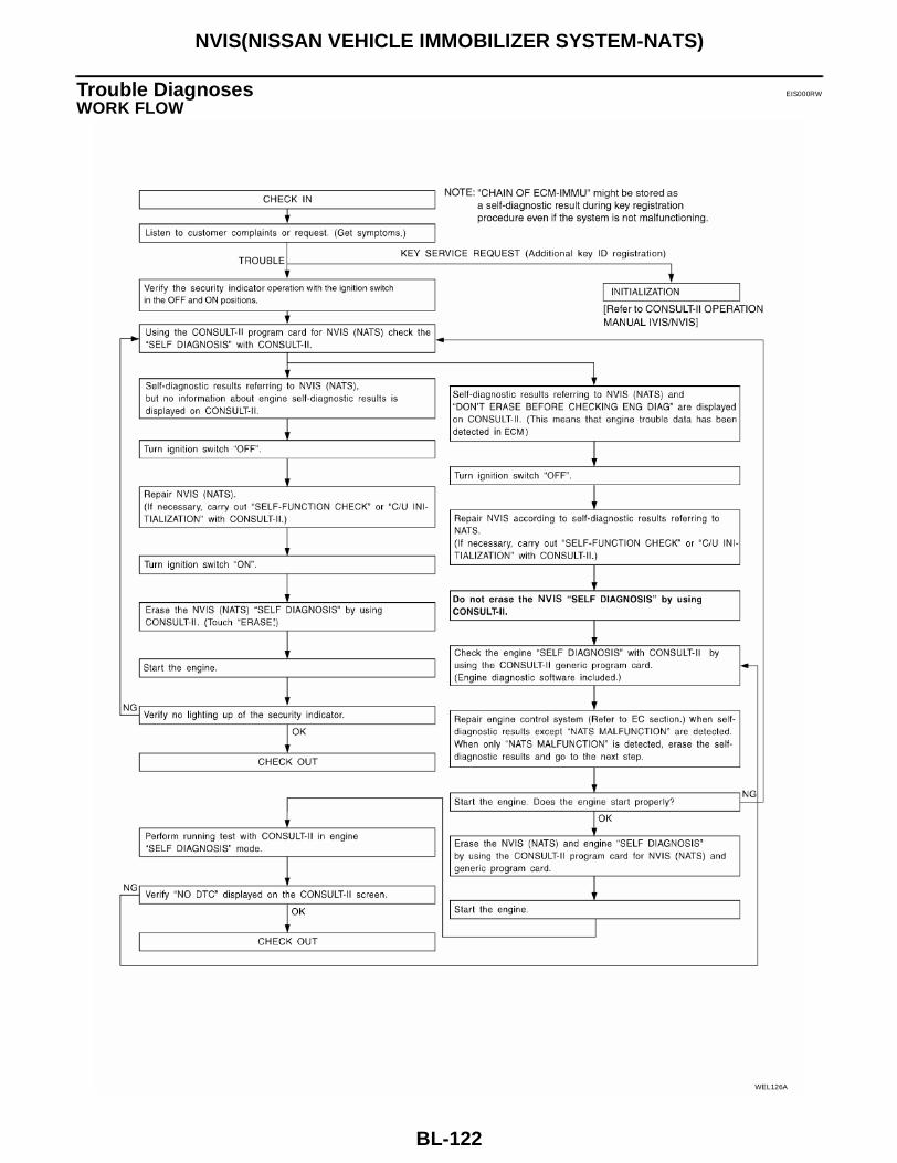
BL-122
NVIS(NISSAN VEHICLE IMMOBILIZER SYSTEM-NATS)
Trouble Diagnoses EIS000RW
WORK FLOW
WEL126A

NVIS(NISSAN VEHICLE IMMOBILIZER SYSTEM-NATS)
BL-123
C
D
E
F
G
H
J
K
L
M
A
B
BL
SYMPTOM MATRIX CHART 1 (SELF-DIAGNOSIS RELATED ITEM)
*: When NVIS (NATS) detects trouble, the security indicator lights up while ignition key is in the “ON” position.
SYMPTOM MATRIX CHART 2 (NON SELF-DIAGNOSIS RELATED ITEM)
SYMPTOMDisplayed “SELF-DIAG
RESULTS” on CON-SULT-II screen.
DIAGNOSTIC PROCE-DURE
(Reference page)
SYSTEM(Malfunctioning part or
mode)
REFERENCE PART NO. OF ILLUSTRATION, BL-
124
ECM INT CIRC-IMMUPROCEDURE 1
BL-124ECM B
● Security indicator lighting up*
● Engine cranks but will not start
In rare cases, "CHAIN OF ECM-IMMU" might be stored during key registration procedure, even if the system is not malfunctioning.
—
CHAIN OF ECM-IMMUPROCEDURE 2
BL-125
Open circuit in battery voltage line of IMMU cir-cuit
C1
Open circuit in ignition line of IMMU circuit
C2
Open circuit in ground line of IMMU circuit
C3
Open circuit in commu-nication line between IMMU and ECM
C4
Short circuit between IMMU and ECM commu-nication line and battery voltage line
C4
Short circuit between IMMU and ECM commu-nication line and ground line
C4
ECM B
IMMU A
DIFFERENCE OF KEYPROCEDURE 3
BL-128
Unregistered key D
IMMU A
CHAIN OF IMMU-KEYPROCEDURE 4
BL-129
Malfunction of key ID chip
E
IMMU A
ID DISCORD, IMM-ECMPROCEDURE 5
BL-130
System initialization has not yet been completed
F
ECM F
LOCK MODEPROCEDURE 7
BL-133LOCK MODE D
● MIL staying ON
● Security indicator lighting up*
DON'T ERASE BEFORE CHECKING ENG DIAG
WORK FLOWBL-122
Engine trouble data and NVIS (NATS) trouble data have been detected in ECM
—
SYMPTOMDIAGNOSTIC PROCEDURE
(Reference page)SYSTEM
(Malfunctioning part or mode)
Security indicator lamp does not light up.PROCEDURE 6
BL-131
Security indicator lamp
Open circuit between fuse and IMMU
Continuation of initialization mode
IMMU

BL-124
NVIS(NISSAN VEHICLE IMMOBILIZER SYSTEM-NATS)
DIAGNOSTIC SYSTEM DIAGRAM
DIAGNOSTIC PROCEDURE 1Self-diagnostic results:“ECM INT CIRC-IMMU” displayed on CONSULT-II screen1. Confirm SELF-DIAGNOSTIC RESULTS “ECM INT CIRC-IMMU”
displayed on CONSULT-II screen. Ref. part No. B.2. Replace ECM.3. Perform initialization with CONSULT-II.
For initialization, refer to “CONSULT-II OPERATION MANUALIVIS/NVIS”.
WEL127A
SEL314W

NVIS(NISSAN VEHICLE IMMOBILIZER SYSTEM-NATS)
BL-125
C
D
E
F
G
H
J
K
L
M
A
B
BL
DIAGNOSTIC PROCEDURE 2Self-diagnostic results:“CHAIN OF ECM-IMMU” displayed on CONSULT-II screen
1. CONFIRM SELF-DIAGNOSTIC RESULTS
Confirm SELF-DIAGNOSTIC RESULTS “CHAIN OF ECM-IMMU” displayed on CONSULT-II screen.NOTE:In rare cases, “CHAIN OF ECM-IMMU” might be stored during keyregistration procedure, even if the system is not malfunctioning.Is CONSULT-II screen displayed as shown?Yes >> GO TO 2.No >> GO TO BL-123, "SYMPTOM MATRIX CHART 1 (SELF-
DIAGNOSIS RELATED ITEM)" .
2. CHECK POWER SUPPLY CIRCUIT FOR NVIS (NATS) IMMU
1. Disconnect NVIS (NATS) IMMU connector.2. Check voltage between NVIS (NATS) IMMU harness connector
M27 terminal 8 (W/L) and ground with CONSULT-II or tester.
OK or NGOK >> GO TO 3.NG >> Check the following
● 10A fuse (No. 24, located in the fuse and fusible linkbox)
● Harness for open or short between fuse and NVIS(NATS) IMMU connectorRef. Part No. C1
3. CHECK IGN SW. ON SIGNAL
1. Turn ignition switch ON.2. Check voltage between NVIS (NATS) IMMU harness connector
M27 terminal 7 (R) and ground with CONSULT-II or tester.
OK or NGOK >> GO TO 4.NG >> Check the following
● 10A fuse [No. 1, located in the fuse block (J/B)]● Harness for open or short between fuse and NVIS
(NATS) IMMU connectorRef. part No. C2
SEL292W
Battery voltage should exist.
WIIA0024E
Battery voltage should exist.
WIIA0014E

BL-126
NVIS(NISSAN VEHICLE IMMOBILIZER SYSTEM-NATS)
4. CHECK GROUND CIRCUIT FOR NVIS (NATS) IMMU
1. Turn ignition switch OFF.2. Check harness continuity between NVIS (NATS) IMMU harness
connector M27 terminal 4 (B) and ground.
OK or NGOK >> GO TO 5.NG >> Repair harness. Ref. part No. C3
5. CHECK COMMUNICATION LINE OPEN CIRCUIT
1. Disconnect ECM connector.2. Check harness continuity between ECM harness connector F54
terminal 31 (QR25DE) or 116 (VQ35DE) (L/R) and NVIS (NATS)IMMU connector M27 terminal 1 (L/R).
OK or NGOK >> GO TO 6.NG >> Repair harness or connector. Ref. part No. C4
6. CHECK COMMUNICATION LINE BATTERY SHORT CIRCUIT
1. Turn ignition switch ON.2. Check voltage between ECM harness connector F54 terminal
31 (QR25DE) or 116 (VQ35DE) (L/R) or NVIS (NATS) IMMUharness connector M27 terminal 1 (L/R) and ground.
OK or NGOK >> GO TO 7.NG >> ● Communication line is short-circuited with battery
voltage line or ignition switch ON line.● Repair harness or connectors.
Ref. part No. C4
Continuity should exist.
WIIA0025E
Continuity should exist.
WIIA0026E
Voltage : 0V
WIIA0027E

NVIS(NISSAN VEHICLE IMMOBILIZER SYSTEM-NATS)
BL-127
C
D
E
F
G
H
J
K
L
M
A
B
BL
7. CHECK COMMUNICATION LINE GROUND SHORT CIRCUIT
1. Turn ignition switch OFF.2. Check continuity between ECM harness connector F54 terminal
31 (QR25DE) or 116 (VQ35DE) (L/R) or NVIS (NATS) IMMUconnector M27 terminal 1 (L/R) and ground.
OK or NGOK >> GO TO 8.NG >> ● Communication line is short-circuited with ground
line.● Repair harness or connectors.
Ref. part No. C4
8. SIGNAL FROM ECM TO NVIS (NATS) IMMU CHECK
1. Check the signal between ECM harness connector F54 terminal 31 (QR25DE) or 116 (VQ35DE) (L/R)and ground with CONSULT-II or oscilloscope when ignition switch is turned “ON”.
2. Make sure signals which are shown in the figure below can be detected during 750 msec. just after igni-tion switch is turned “ON”.
OK or NGOK >> ● NVIS (NATS) IMMU is malfunctioning.
● Replace NVIS (NATS) IMMU. Ref. part No. A● Perform initialization with CONSULT-II.● For the operation of initialization, refer to “CONSULT-II OPERATION MANUAL IVIS/NVIS”.
NG >> ● ECM is malfunctioning.● Replace ECM. Ref. part No. B● Perform initialization with CONSULT-II.● For the operation of initialization, refer to “CONSULT-II OPERATION MANUAL IVIS/NVIS”.
Continuity should not exist.
WIIA0028E
LEL641
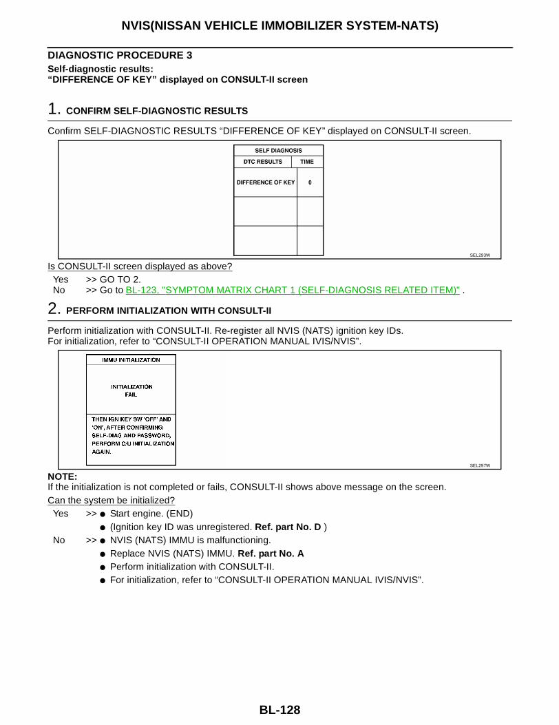
BL-128
NVIS(NISSAN VEHICLE IMMOBILIZER SYSTEM-NATS)
DIAGNOSTIC PROCEDURE 3Self-diagnostic results:“DIFFERENCE OF KEY” displayed on CONSULT-II screen
1. CONFIRM SELF-DIAGNOSTIC RESULTS
Confirm SELF-DIAGNOSTIC RESULTS “DIFFERENCE OF KEY” displayed on CONSULT-II screen.
Is CONSULT-II screen displayed as above?Yes >> GO TO 2.No >> Go to BL-123, "SYMPTOM MATRIX CHART 1 (SELF-DIAGNOSIS RELATED ITEM)" .
2. PERFORM INITIALIZATION WITH CONSULT-II
Perform initialization with CONSULT-II. Re-register all NVIS (NATS) ignition key IDs.For initialization, refer to “CONSULT-II OPERATION MANUAL IVIS/NVIS”.
NOTE:If the initialization is not completed or fails, CONSULT-II shows above message on the screen.Can the system be initialized?
Yes >> ● Start engine. (END)● (Ignition key ID was unregistered. Ref. part No. D )
No >> ● NVIS (NATS) IMMU is malfunctioning.● Replace NVIS (NATS) IMMU. Ref. part No. A● Perform initialization with CONSULT-II.● For initialization, refer to “CONSULT-II OPERATION MANUAL IVIS/NVIS”.
SEL293W
SEL297W

NVIS(NISSAN VEHICLE IMMOBILIZER SYSTEM-NATS)
BL-129
C
D
E
F
G
H
J
K
L
M
A
B
BL
DIAGNOSTIC PROCEDURE 4Self-diagnostic results:“CHAIN OF IMMU-KEY” displayed on CONSULT-II screen
1. CONFIRM SELF-DIAGNOSTIC RESULTS
Confirm SELF-DIAGNOSTIC RESULTS “CHAIN OF IMMU-KEY” displayed on CONSULT-II screen.
Is CONSULT-II screen displayed as above?Yes >> GO TO 2.No >> Go to BL-123, "SYMPTOM MATRIX CHART 1 (SELF-DIAGNOSIS RELATED ITEM)" .
2. CHECK NVIS (NATS) IGNITION KEY ID CHIP
Start engine with another registered NVIS (NATS) ignition key.Does the engine start?Yes >> ● Ignition key ID chip is malfunctioning.
● Replace the ignition key.● Ref. part No. E● Perform initialization with CONSULT-II.● For initialization, refer to “CONSULT-II OPERATION MANUAL IVIS/NVIS”.
No >> GO TO 3.
3. CHECK NVIS (NATS) IMMU INSTALLATION
Check NVIS (NATS) IMMU installation.Refer to BL-134, "How to Replace NVIS (NATS) IMMU" .OK or NGOK >> ● NVIS (NATS) IMMU is malfunctioning.
● Replace NVIS (NATS) IMMU. Ref. part No. A● Perform initialization with CONSULT-II.● For initialization, refer to “CONSULT-II OPERATION MANUAL IVIS/NVIS”.
NG >> Reinstall NVIS (NATS) IMMU correctly.
SEL294W

BL-130
NVIS(NISSAN VEHICLE IMMOBILIZER SYSTEM-NATS)
DIAGNOSTIC PROCEDURE 5Self-diagnostic results:“ID DISCORD, IMM-ECM” displayed on CONSULT-II screen
1. CONFIRM SELF-DIAGNOSTIC RESULTS
Confirm SELF-DIAGNOSTIC RESULTS “ID DISCORD, IMM-ECM” displayed on CONSULT-II screen.
NOTE:“ID DISCORD IMM-ECM”:Registered ID of NVIS (NATS) IMMU is in discord with that of ECM.Is CONSULT-II screen displayed as above?
Yes >> GO TO 2.No >> Go to BL-123, "SYMPTOM MATRIX CHART 1 (SELF-DIAGNOSIS RELATED ITEM)" .
2. PERFORM INITIALIZATION WITH CONSULT-II
Perform initialization with CONSULT-II. Re-register all NVIS (NATS) ignition key IDs.For initialization, refer to “CONSULT-II OPERATION MANUAL IVIS/NVIS”.
NOTE:If the initialization is not completed or fails, CONSULT-II shows above message on the screen.Can the system be initialized?
Yes >> ● Start engine. (END)● (System initialization had not been completed. Ref. part No. F )
No >> ● ECM is malfunctioning.● Replace ECM. Ref. part No. F● Perform initialization with CONSULT-II.● For initialization, refer to “CONSULT-II OPERATION MANUAL IVIS/NVIS”.
SEL298W
SEL297W

NVIS(NISSAN VEHICLE IMMOBILIZER SYSTEM-NATS)
BL-131
C
D
E
F
G
H
J
K
L
M
A
B
BL
DIAGNOSTIC PROCEDURE 6“SECURITY INDICATOR LAMP DOES NOT LIGHT UP”
1. CHECK FUSE
Check 10A fuse [No. 19, located in the fuse block (J/B)].Is 10A fuse OK?Yes >> GO TO 2.No >> Replace fuse.
2. CHECK SECURITY INDICATOR LAMP
1. Install 10A fuse.2. Perform initialization with CONSULT-II.
For initialization, refer to “CONSULT-II OPERATION MANUAL IVIS/NVIS”.3. Turn ignition switch OFF.4. Start engine and turn ignition switch OFF.5. Check the security indicator lamp lighting.Security indicator lamp should light up.OK or NGOK >> INSPECTION ENDNG >> GO TO 3.
3. CHECK SECURITY INDICATOR LAMP POWER SUPPLY CIRCUIT
1. Disconnect security indicator lamp connector.2. Check voltage between security indicator lamp connector M14
terminal 1 (Y/R) and ground.
OK or NGOK >> GO TO 4.NG >> Check harness for open or short between fuse and
security indicator lamp.
4. CHECK SECURITY INDICATOR LAMP
Check security indicator lamp.Is security indicator lamp OK?Yes >> GO TO 5.No >> Replace security indicator lamp.
Battery voltage should exist.
WIIA0029E

BL-132
NVIS(NISSAN VEHICLE IMMOBILIZER SYSTEM-NATS)
5. CHECK NVIS (NATS) IMMU FUNCTION
1. Connect NVIS (NATS) IMMU connector.2. Disconnect security indicator lamp connector.3. Check continuity between NVIS (NATS) IMMU connector M27
terminal 5 (G/OR) and ground.
OK or NGOK >> Check harness for open or short between security indi-
cator lamp and NVIS (NATS) IMMU.NG >> ● NVIS (NATS) IMMU is malfunctioning.
● Replace NVIS (NATS) IMMU.● Perform initialization with CONSULT-II.● For initialization, refer to “CONSULT-II OPERATION
MANUAL IVIS/NVIS”.
Continuity should exist intermittently.
WIIA0030E

NVIS(NISSAN VEHICLE IMMOBILIZER SYSTEM-NATS)
BL-133
C
D
E
F
G
H
J
K
L
M
A
B
BL
DIAGNOSTIC PROCEDURE 7Self-diagnostic results:“LOCK MODE” displayed on CONSULT-II screen
1. CONFIRM SELF-DIAGNOSTIC RESULTS
Confirm SELF-DIAGNOSTIC RESULTS “LOCK MODE” is displayed on CONSULT-II screen.
Is CONSULT-II screen displayed as above?Yes >> GO TO 2.No >> Go to BL-123, "SYMPTOM MATRIX CHART 1 (SELF-DIAGNOSIS RELATED ITEM)" .
2. ESCAPE FROM LOCK MODE
1. Turn ignition switch OFF.2. Turn ignition switch ON with registered key. (Do not start engine.) Wait 5 seconds.3. Return the key to OFF position.4. Repeat steps 2 and 3 twice (total of three cycles).5. Start the engine.Does engine start?Yes >> ● System is OK.
● (Now system is escaped from “LOCK MODE”.)No >> GO TO 3.
3. CHECK NVIS (NATS) IMMU ILLUSTRATION
Check NVIS (NATS) IMMU installation. Refer to BL-134, "How to Replace NVIS (NATS) IMMU" .OK or NGOK >> GO TO 4.NG >> Reinstall NVIS (NATS) IMMU correctly.
SEL295W

BL-134
NVIS(NISSAN VEHICLE IMMOBILIZER SYSTEM-NATS)
4. PERFORM INITIALIZATION WITH CONSULT-II
Perform initialization with CONSULT-II.For initialization, refer to “CONSULT-II OPERATION MANUAL IVIS/NVIS”.
NOTE:If the initialization is not completed or fails, CONSULT-II shows the above message on the screen.Can the system be initialized?
Yes >> System is OK.No >> Check “CHAIN OF IMMU-KEY”. Refer to BL-129, "DIAGNOSTIC PROCEDURE 4" .
How to Replace NVIS (NATS) IMMU EIS000RX
NOTE:● If NVIS (NATS) IMMU is not installed correctly, NVIS (NATS)
system will not operate properly and SELF-DIAG RESULTSon CONSULT-II screen will show “LOCK MODE” or “CHAINOF IMMU-KEY”.
SEL297W
SEL096WA

INTEGRATED HOMELINK TRANSMITTER
BL-135
C
D
E
F
G
H
J
K
L
M
A
B
BL
INTEGRATED HOMELINK TRANSMITTER PFP:96401
Wiring Diagram —TRNSCV— EIS000RY
LIWA0040E
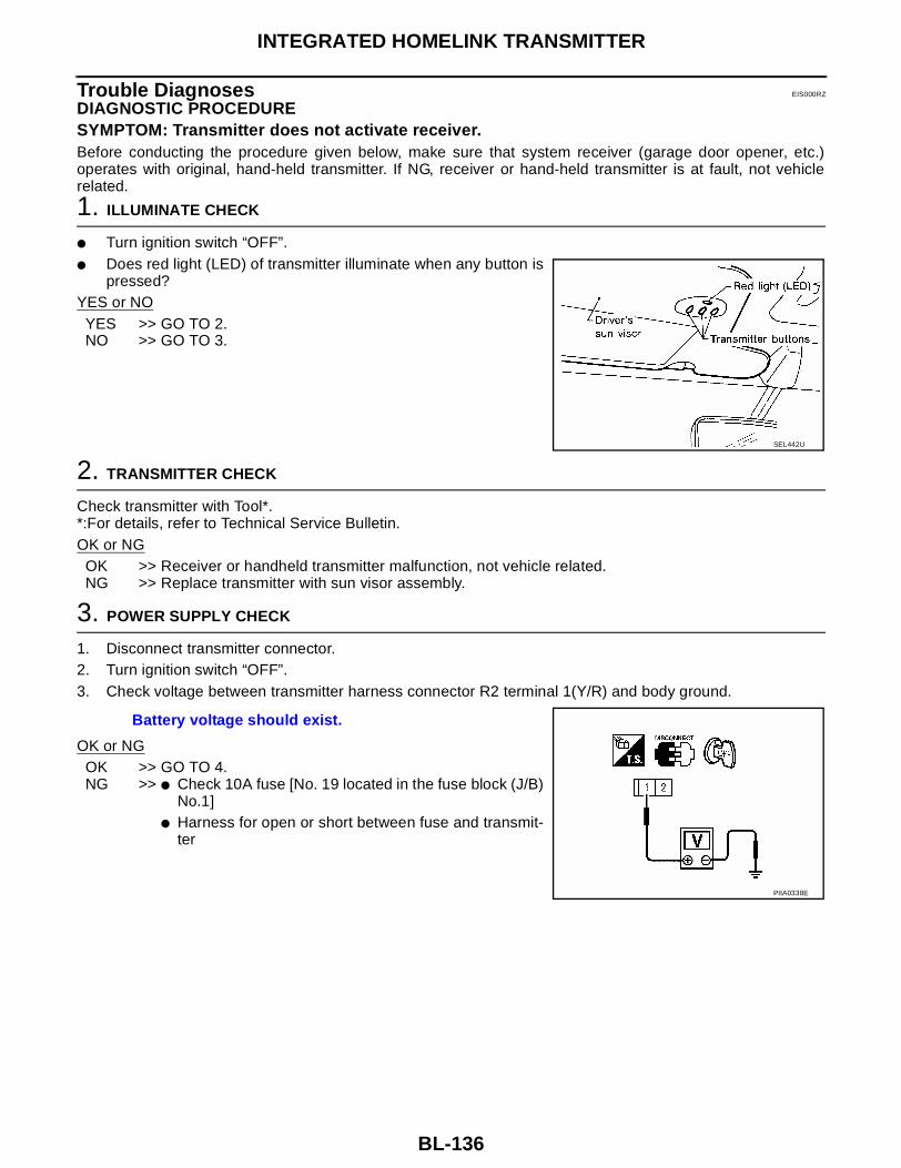
BL-136
INTEGRATED HOMELINK TRANSMITTER
Trouble Diagnoses EIS000RZ
DIAGNOSTIC PROCEDURESYMPTOM: Transmitter does not activate receiver.Before conducting the procedure given below, make sure that system receiver (garage door opener, etc.)operates with original, hand-held transmitter. If NG, receiver or hand-held transmitter is at fault, not vehiclerelated.
1. ILLUMINATE CHECK
● Turn ignition switch “OFF”.● Does red light (LED) of transmitter illuminate when any button is
pressed?YES or NO
YES >> GO TO 2.NO >> GO TO 3.
2. TRANSMITTER CHECK
Check transmitter with Tool*.*:For details, refer to Technical Service Bulletin.OK or NG
OK >> Receiver or handheld transmitter malfunction, not vehicle related.NG >> Replace transmitter with sun visor assembly.
3. POWER SUPPLY CHECK
1. Disconnect transmitter connector.2. Turn ignition switch “OFF”.3. Check voltage between transmitter harness connector R2 terminal 1(Y/R) and body ground.
OK or NGOK >> GO TO 4.NG >> ● Check 10A fuse [No. 19 located in the fuse block (J/B)
No.1]● Harness for open or short between fuse and transmit-
ter
SEL442U
Battery voltage should exist.
PIIA0338E

INTEGRATED HOMELINK TRANSMITTER
BL-137
C
D
E
F
G
H
J
K
L
M
A
B
BL
4. GROUND CIRCUIT CHECK
Check continuity between transmitter harness connector R2 terminal 2 (B) and body ground.
OK or NGOK >> Replace transmitter with sun visor assembly.NG >> Repair harness.
Continuity should exist.
PIIA0339E

BL-138
BODY REPAIR
BODY REPAIR PFP:60100
Body Exterior Paint Color EIS000S0
S: Solid Paint, 2S: Solid Color with Clear, 2M: Metallic with Clear, 2P:2-Coat Pearl, 3P:3-Coat Pearl
LIIA0126E
Component
Color code
BAX3 BBX4 BDY2 BEY1 BFY0 BKH3 BKY1 BKY2 BQM1 BQX3
Descrip-tion
Nou-veau Ruby
Opal Blue
Metal-lic
Mystic Emer-
ald
Velvet Beige
Sea-scape
Super Black
Sheer Silver
Pol-ished
Pewter
Cloud White
Satin White
Paint type
2P 2M 2M 2M 2M 2S 2M 2M S 3P
Hard clear coat
X X X X X X X X X X
1Bumper fascia
BodyBody color
BAX3 BBX4 BDY2 BEY1 BFY0 BKH3 BKY1 BKY2 BQM1 BQX3
2Radia-tor grille
Cen-ter
Black AG01 AG01 AG01 AG01 AG01 AG01 AG01 AG01 AG01 AG01
Outer Chrome Cr Cr Cr Cr Cr Cr Cr Cr Cr Cr
3Outside mirror
BodyBody color
BAX3 BBX4 BDY2 BEY1 BFY0 BKH3 BKY1 BKY2 BQM1 BQX3
Base Black AG01 AG01 AG01 AG01 AG01 AG01 AG01 AG01 AG01 AG01
4Side guard molding
BodyBody color
BAX3 BBX4 BDY2 BEY1 BFY0 BKH3 BKY1 BKY2 BQM1 BQX3
Base Black AG01 AG01 AG01 AG01 AG01 AG01 AG01 AG01 AG01 AG01
5Door sash
Black tape
X X X X X X X X X X
6Outsidehandle
Body color
BAX3 BBX4 BDY2 BEY1 BFY0 BKH3 BKY1 BKY2 BQM1 BQX3
7Rear Spoiler
Body color
BAX3 BBX4 BDY2 BEY1 BFY0 BKH3 BKY1 BKY2 BQM1 BQX3
8Trunk lid finisher
Body color
BAX3 BBX4 BDY2 BEY1 BFY0 BKH3 BKY1 BKY2 BQM1 BQX3
9Center mudgaurd
Body color
BAX3 BBX4 BDY2 BEY1 BFY0 BKH3 BKY1 BKY2 BQM1 BQX3
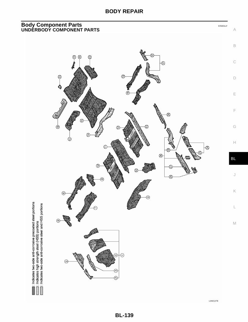
BODY REPAIR
BL-139
C
D
E
F
G
H
J
K
L
M
A
B
BL
Body Component Parts EIS001LF
UNDERBODY COMPONENT PARTS
LIIA0127E

BL-140
BODY REPAIR
1. Hoodledge assembly (RH, LH)2. Hoodledge reinforcement (RH, LH)3. Upper hoodledge (RH, LH)4. Lower front hoodledge (RH, LH)5. Rear hoodledge reinforcement (RH, LH)6. Upper dash crossmember assembly7. Upper dash assembly8. Side cowl top9. Lower dash10. Side dash (RH, LH)11. Front floor center12. Front floor13. Inner sill (RH, LH)14. Rear seat crossmember assembly15. Rear floor front16. Rear seat crossmember17. Rear floor belt anchor reinforcement18. Rear seat back support assembly19. Center rear crossmember20. Rear floor rear21. Muffler mounting bracket22. Rear floor side (RH, LH)23. Spare tire clamp bracket24. Front side member closing plate assembly (RH, LH)25. Front side member closing plate (RH, LH)26. Front side member assembly (RH, LH)27. Front side member (RH, LH)28. Front side member outrigger assembly (RH, LH)29. Front side member patch (RH, LH)30. Front side member rear extension (RH, LH)31. Rear side member (RH, LH)32. Rear side member extension (RH, LH)

BODY REPAIR
BL-141
C
D
E
F
G
H
J
K
L
M
A
B
BL
BODY COMPONENT PARTS
LIIA0128E

BL-142
BODY REPAIR
1. Hood2. Front fender (RH, LH)3. Front fender bracket (RH, LH)4. Body side assembly (RH, LH)5. Outer body side assembly (RH, LH)6. Inner center pillar (RH, LH)7. Upper inner front pillar (RH, LH)8. Lower front pillar reinforcement (RH, LH)9. Side parcel shelf (RH, LH)10. Inner rear pillar (RH, LH)11. Rear seat back support brace12. Inner rear wheelhouse (RH, LH)13. Outer rear wheelhouse (RH, LH)14. Outer rear wheelhouse extension (RH, LH)15. Rear floor side extension (RH, LH)16. Rear seat crossmember reinforcement (RH, LH)17. Roof18. Front roof rail19. Rear roof rail20. Front roof bow 21. Roof reinforcement22. Center roof bow23. Rear roof bow24. Rear fender (RH, LH)25. Rear fender drip (RH, LH)26. Rear fender corner (RH, LH)27. Striker retainer (RH, LH)28. Fuel filler lid base29. Fuel filler lid30. Trunk lid31. Rear waist and parcel shelf32. Rear panel assembly33. Rear bumper side bracket34. Rear bumper side bracket35. Rear panel upper stiffener36. Front door assembly (RH, LH)37. Outer front door panel (RH, LH)38. Rear door assembly (RH, LH)39. Outer rear door panel (RH, LH)40. Rear combination lamp base (RH, LH)41. Front pillar reinforcement assembly (RH, LH)42. Center pillar reinforcement (RH, LH)43. Outer sill reinforcement44. Rear bumper reinforcement45. Front bumper reinforcement

BODY REPAIR
BL-143
C
D
E
F
G
H
J
K
L
M
A
B
BL
Corrosion Protection EIS001LG
DESCRIPTIONTo provide improved corrosion prevention, the following anti-corrosive measures have been implemented inNISSAN production plants. When repairing or replacing body panels, it is necessary to use the same anti-cor-rosive measures.
ANTI-CORROSIVE PRECOATED STEEL (GALVANNEALED STEEL)To improve repairability and corrosion resistance, a new type of anti-corrosive precoated steel sheet has been adopted replacing conven-tional zinc-coated steel sheet.Galvannealed steel is electroplated and heated to form Zinc-ironalloy, which provides excellent and long term corrosion resistancewith cationic electrodeposition primer.
Nissan Genuine Service Parts are fabricated from galvannealed steel. Therefore, it is recommended thatGENUINE NISSAN PARTS or equivalent be used for panel replacement to maintain the anti-corrosive perfor-mance built into the vehicle at the factory.
PHOSPHATE COATING TREATMENT AND CATIONIC ELECTRODEPOSITION PRIMERA phosphate coating treatment and a cationic electrodeposition primer, which provide excellent corrosion pro-tection, are employed on all body components.CAUTION:Confine paint removal during welding operations to an absoluteminimum.
Nissan Genuine Service Parts are also treated in the same manner. Therefore, it is recommended that GENU-INE NISSAN PARTS or equivalent be used for panel replacement to maintain anti-corrosive performance builtinto the vehicle at the factory.
PIIA0093E
PIIA0095E

BL-144
BODY REPAIR
ANTI-CORROSIVE WAXTo improve corrosion resistance, anti-corrosive wax is applied inside the body sill and inside other closed sec-tions. Accordingly, when replacing these parts, be sure to apply anti-corrosive wax to the appropriate areas ofthe new parts. Select an excellent anti-corrosive wax which will penetrate after application and has a long shelflife.
LIIA0005E

BODY REPAIR
BL-145
C
D
E
F
G
H
J
K
L
M
A
B
BL
UNDERCOATINGThe underside of the floor and wheelhouse are undercoated to prevent rust, vibration, noise and stone chip-ping. Therefore, when such a panel is replaced or repaired, apply undercoating to that part. Use an under-coating which is rust preventive, soundproof, vibration-proof, shock-resistant, adhesive, and durable.
Precautions in undercoating1. Do not apply undercoating to any place unless specified (such as the areas above the muffler and three
way catalyst which are subjected to heat).2. Do not undercoat the exhaust pipe or other parts which become hot.3. Do not undercoat rotating parts.4. Apply bitumen wax after applying undercoating.
LIIA0129E

BL-146
BODY REPAIR
Body Sealing EIS001LH
DESCRIPTIONThe following figure shows the areas which are sealed at the factory. Sealant which has been applied to theseareas should be smooth and free from cuts or gaps. Care should be taken not to apply an excess amount ofsealant and not to allow other unaffected parts to come into contact with the sealant.
WIIA0138E

BODY REPAIR
BL-147
C
D
E
F
G
H
J
K
L
M
A
B
BL
WIIA0129E

BL-148
BODY REPAIR
WIIA0130E

BODY REPAIR
BL-149
C
D
E
F
G
H
J
K
L
M
A
B
BL
Body Construction EIS001LI
BODY CONSTRUCTION
WIIA0131E

BL-150
BODY REPAIR
Body Alignment EIS001LJ
BODY CENTER MARKSA mark has been placed on each part of the body to indicate the vehicle center. When repairing parts dam-aged by an accident which might affect the vehicle frame (members, pillars, etc.), more accurate and effectiverepair will be possible by using these marks together with body alignment specifications.
WIIA0147E
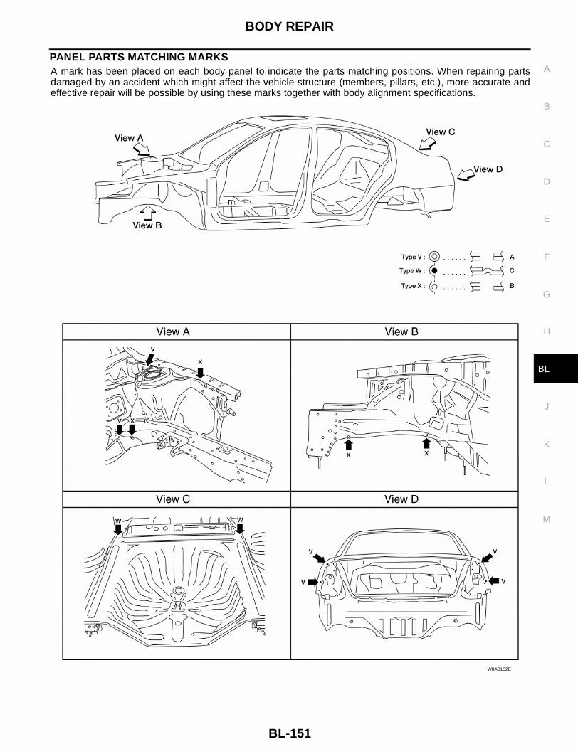
BODY REPAIR
BL-151
C
D
E
F
G
H
J
K
L
M
A
B
BL
PANEL PARTS MATCHING MARKSA mark has been placed on each body panel to indicate the parts matching positions. When repairing partsdamaged by an accident which might affect the vehicle structure (members, pillars, etc.), more accurate andeffective repair will be possible by using these marks together with body alignment specifications.
WIIA0132E

BL-152
BODY REPAIR
DESCRIPTION● All dimensions indicated in the figures are actual.● When using a tracking gauge, adjust both pointers to equal length. Then check the pointers and gauge
itself to make sure there is no free play.● When a measuring tape is used, check to be sure there is no elongation, twisting or bending.● Measurements should be taken at the center of the mounting holes.● An asterisk (*) following the value at the measuring point indicates that the measuring point on the other
side is symmetrically the same value.● The coordinates of the measurement points are the distances measured from the standard line of "X", "Y"
and "Z".
PIIA0104E

BODY REPAIR
BL-153
C
D
E
F
G
H
J
K
L
M
A
B
BL
ENGINE COMPARTMENTMEASUREMENT
WIIA0148E

BL-154
BODY REPAIR
MEASUREMENT POINTS
WIIA0149E
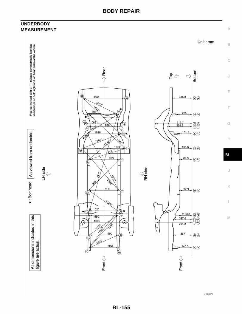
BODY REPAIR
BL-155
C
D
E
F
G
H
J
K
L
M
A
B
BL
UNDERBODYMEASUREMENT
LIIA0087E

BL-156
BODY REPAIR
MEASUREMENT POINTS
LIIA0086E

BODY REPAIR
BL-157
C
D
E
F
G
H
J
K
L
M
A
B
BL
PASSENGER COMPARTMENTMEASUREMENT
LIIA0090E
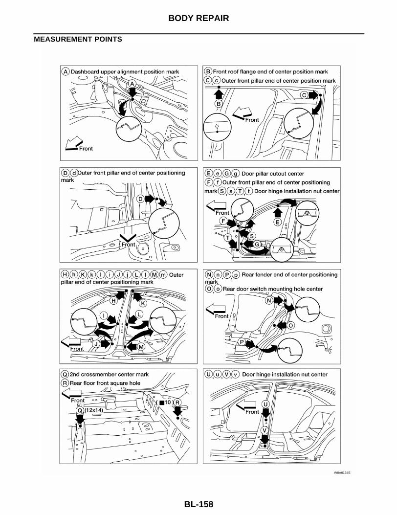
BL-158
BODY REPAIR
MEASUREMENT POINTS
WIIA0134E

BODY REPAIR
BL-159
C
D
E
F
G
H
J
K
L
M
A
B
BL
REAR BODYMEASUREMENT
LIIA0065E

BL-160
BODY REPAIR
MEASUREMENT POINTS
LIIA0066E

BODY REPAIR
BL-161
C
D
E
F
G
H
J
K
L
M
A
B
BL
Handling Precautions for Plastics EIS001LK
HANDLING PRECAUTIONS FOR PLASTICS
1. When repairing and painting a portion of the body adjacent to plastic parts, consider their characteristics(influence of heat and solvent) and remove them if necessary or take suitable measures to protect them.
2. Plastic parts should be repaired and painted using methods suiting the materials, characteristics.
Abbre-viation
Material nameHeat resisting temperature
°C (°F)
Resistance to gasoline and solvents
Other cautions
PE Polyethylene 60 (140)Gasoline and most solvents are harmless if applied for a very short time (wipe up quickly).
Flammable
PVC Polyvinyl Chloride 80 (176) Same as above.Poison gas is emitted when burned.
EPM/EPDM
Ethylene Propylene (Diene) rub-ber
80 (176) Same as above. Flammable
TPO/TPR
Thermoplastic Olefine/Thermoplastic Rubber
80 (176) Same as above. Flammable
PP Polypropylene 90 (194) Same as above.Flammable, avoid bat-tery acid.
UP Polyester thermoset 90 (194) Same as above. Flammable
PS Polystyrene 80 (176) Avoid solvents. Flammable
ABSAcrylonitrile Butadiene Styrene resin
80 (176) Avoid gasoline and solvents.
AES Acrylonitrile Ethylene Styrene 80 (176) Same as above.
PMMA Polymethyl Methacrylate 85 (185) Same as above.
AAS Acrylonitrile Acrylic Styrene 85 (185) Same as above.
AS Acrylonitrile Styrene 85 (185) Same as above.
EVA Polyvinyl Ethyl Acetate 90 (194) Same as above.
ASA Acrylonitrile Styrene Acrylate 100 (222) Same as above. Flammable
PPO/PPE
Polyphenylene Oxide/Polyphenylene Ether
110 (230) Same as above.
PC Polycarbonate 120 (248) Same as above.
PAR Polyacrylate 180 (356) Same as above.
L-LDPE
Lenear Low Density PE 45 (100)Gasoline and most solvents are harmless.
Flammable
PUR Polyurethane 90 (194) Same as above.
TPU Thermoplastic Urethane 110 (230) Same as above.
PPC Polypropylene Composite 115 (239) Same as above. Flammable
POM Polyacetal 120 (248) Same as above. Avoid battery acid.
PBT+PC
Polybutylene Terephtha-late+Polycarbonate
120 (248) Same as above. Flammable
PA Polyamide (Nylon) 140 (284) Same as above.Avoid immersing in wa-ter.
PBT Polybutylene Terephthalate 140 (284) Same as above.
FRP Fiber Reinforced Plastics 170 (338) Same as above. Avoid battery acid.
PET Polyethylene Terephthalate 180 (356) Same as above.
PEI Polyetherimide 200 (392) Same as above.
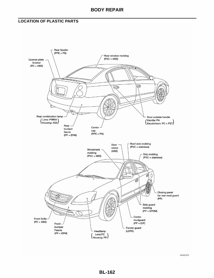
BL-162
BODY REPAIR
LOCATION OF PLASTIC PARTS
WIIA0157E

BODY REPAIR
BL-163
C
D
E
F
G
H
J
K
L
M
A
B
BL
WIIA0150E
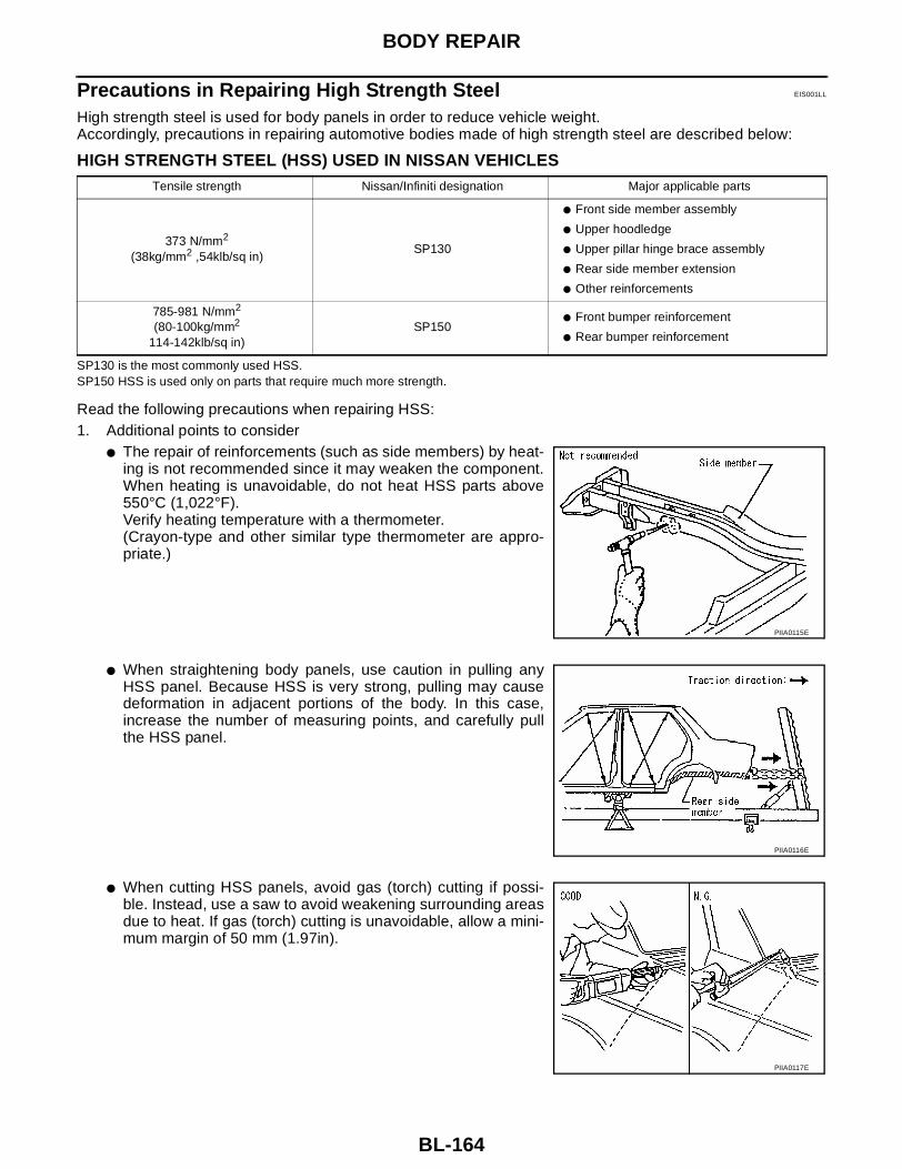
BL-164
BODY REPAIR
Precautions in Repairing High Strength Steel EIS001LL
High strength steel is used for body panels in order to reduce vehicle weight.Accordingly, precautions in repairing automotive bodies made of high strength steel are described below:
HIGH STRENGTH STEEL (HSS) USED IN NISSAN VEHICLES
SP130 is the most commonly used HSS.SP150 HSS is used only on parts that require much more strength.
Read the following precautions when repairing HSS:1. Additional points to consider
● The repair of reinforcements (such as side members) by heat-ing is not recommended since it may weaken the component.When heating is unavoidable, do not heat HSS parts above550°C (1,022°F).Verify heating temperature with a thermometer.(Crayon-type and other similar type thermometer are appro-priate.)
● When straightening body panels, use caution in pulling anyHSS panel. Because HSS is very strong, pulling may causedeformation in adjacent portions of the body. In this case,increase the number of measuring points, and carefully pullthe HSS panel.
● When cutting HSS panels, avoid gas (torch) cutting if possi-ble. Instead, use a saw to avoid weakening surrounding areasdue to heat. If gas (torch) cutting is unavoidable, allow a mini-mum margin of 50 mm (1.97in).
Tensile strength Nissan/Infiniti designation Major applicable parts
373 N/mm2
(38kg/mm2 ,54klb/sq in)SP130
● Front side member assembly
● Upper hoodledge
● Upper pillar hinge brace assembly
● Rear side member extension
● Other reinforcements
785-981 N/mm2
(80-100kg/mm2
114-142klb/sq in)SP150
● Front bumper reinforcement
● Rear bumper reinforcement
PIIA0115E
PIIA0116E
PIIA0117E

BODY REPAIR
BL-165
C
D
E
F
G
H
J
K
L
M
A
B
BL
● When welding HSS panels, use spot welding whenever possi-ble in order to minimize weakening surrounding areas due toheat.If spot welding is impossible, use M.I.G. welding. Do not usegas (torch) welding because it is inferior in welding strength.
● The spot weld on HSS panels is harder than that of an ordi-nary steel panel.Therefore, when cutting spot welds on a HSS panel, use alow speed high torque drill (1,000 to 1,200 rpm) to increasedrill bit durability and facilitate the operation.
● SP150 HSS panels with a tensile strength of 785 to 981 N/mm2 (80 to 100 kg/mm2 , 114 to 142 klb/sq in), used as rein-forcement in the door guard beams, is too strong to repair.When these HSS parts are damaged, the outer panels alsosustain substantial damage; therefore, the assembly partsmust be replaced.
2. Precautions in spot welding HSSThis work should be performed under standard working condi-tions. Always note the following when spot welding HSS:● The electrode tip diameter must be sized properly according
to the metal thickness.
● The panel surfaces must fit flush to each other, leaving nogaps.
PIIA0144E
PIIA0145E
PIIA0146E
PIIA0147E

BL-166
BODY REPAIR
● Follow the specifications for the proper welding pitch.Unit:mm
Thickness (t) Minimum pitch (l)
0.6 (0.024)0.8 (0.031)1.0 (0.039)1.2 (0.047)1.6 (0.063)1.8 (0.071)
10 (0.39) or over12 (0.47) or over18 (0.71) or over20 (0.79) or over27 (1.06) or over31 (1.22) or over
PIIA0148E

BODY REPAIR
BL-167
C
D
E
F
G
H
J
K
L
M
A
B
BL
Replacement Operations EIS001LM
DESCRIPTIONThis section is prepared for technicians who have attained a high level of skill and experience in repairing col-lision-damaged vehicles and also use modern service tools and equipment. Persons unfamiliar with bodyrepair techniques should not attempt to repair collision-damaged vehicles by using this section.
Technicians are also encouraged to read Body Repair Manual (Fundamentals) in order to ensure that the orig-inal functions and quality of the vehicle can be maintained. The Body Repair Manual (Fundamentals) containsadditional information, including cautions and warnings, that are not including in this manual. Techniciansshould refer to both manuals to ensure proper repairs.
Please note that this information is prepared for worldwide usage, and as such, certain procedures may notapply in some regions or countries.

BL-168
BODY REPAIR
The symbols used in this section for cutting and welding / brazing operations are shown below.
PIIA0149E

BODY REPAIR
BL-169
C
D
E
F
G
H
J
K
L
M
A
B
BL
● Front pillar butt joint can be determined anywhere within shadedarea as shown in the figure. The best location for the butt joint isat position A due to the construction of the vehicle. Refer to thefront pillar section.
● Determine cutting position and record distance from the locatingindent. Use this distance when cutting the service part. Cut outerfront pillar over 60 mm above inner front pillar cut position.
● Prepare a cutting jig to make outer pillar easier to cut. Also, thiswill permit service part to be accurately cut at joint position.
● An example of cutting operation using a cutting jig is as follows.1. Mark cutting lines.
A: Cut position of outer pillarB: Cut position of inner pillar
2. Align cutting line with notch on jig. Clamp jig to pillar.3. Cut outer pillar along groove of jig. (At position A)4. Remove jig and cut remaining portions.5. Cut inner pillar at position B in same manner.
PIIA0150E
PIIA0151E
PIIA0152E
PIIA0153E
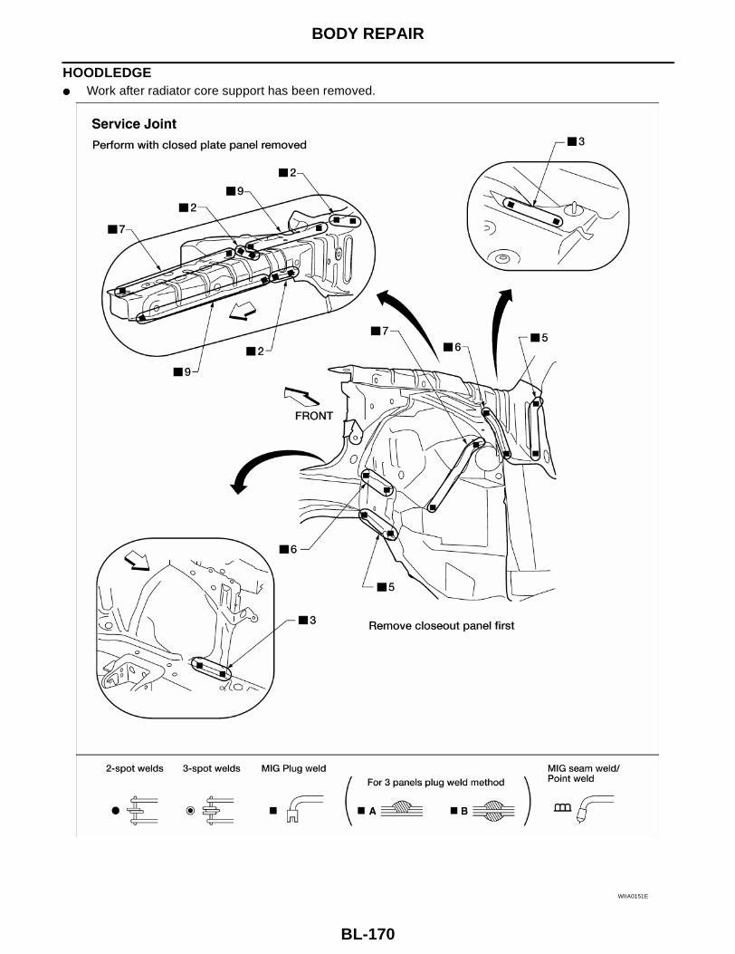
BL-170
BODY REPAIR
HOODLEDGE● Work after radiator core support has been removed.
WIIA0151E

BODY REPAIR
BL-171
C
D
E
F
G
H
J
K
L
M
A
B
BL
HOODLEDGE (PARTIAL REPLACEMENT)● Work after radiator core support has been removed.
WIIA0152E

BL-172
BODY REPAIR
FRONT SIDE MEMBER● Work after hoodledge and radiator core support have been removed.
LIIA0136E

BODY REPAIR
BL-173
C
D
E
F
G
H
J
K
L
M
A
B
BL
FRONT SIDE MEMBER (PARTIAL REPLACEMENT)● Work after radiator core support has been removed.
WIIA0158E
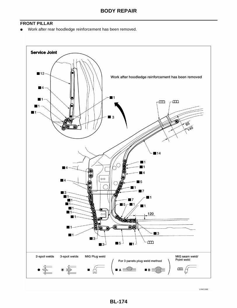
BL-174
BODY REPAIR
FRONT PILLAR● Work after rear hoodledge reinforcement has been removed.
LIIA0138E

BODY REPAIR
BL-175
C
D
E
F
G
H
J
K
L
M
A
B
BL
WIIA0153E
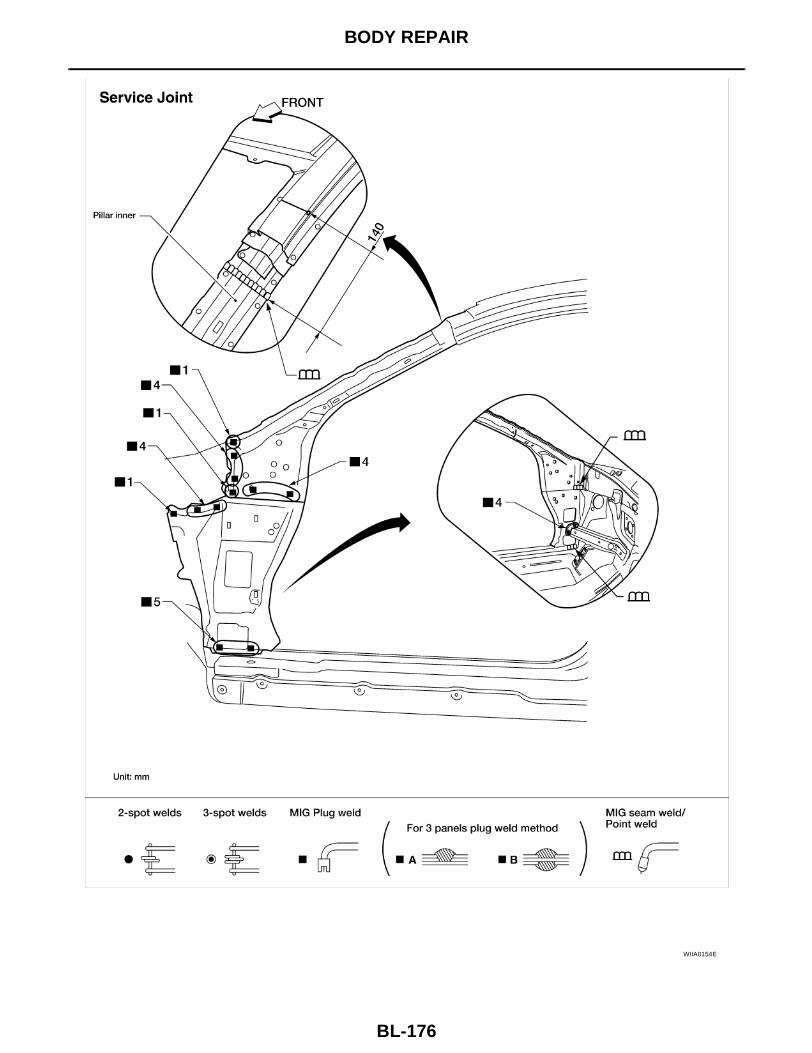
BL-176
BODY REPAIR
WIIA0154E

BODY REPAIR
BL-177
C
D
E
F
G
H
J
K
L
M
A
B
BL
CENTER PILLAR
LIIA0141E

BL-178
BODY REPAIR
OUTER SILL
LIIA0142E

BODY REPAIR
BL-179
C
D
E
F
G
H
J
K
L
M
A
B
BL
REAR FENDER
WIIA0155E

BL-180
BODY REPAIR
REAR PANEL
LIIA0144E
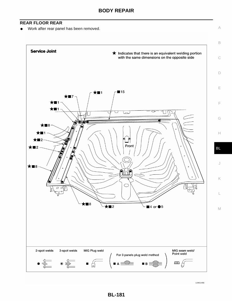
BODY REPAIR
BL-181
C
D
E
F
G
H
J
K
L
M
A
B
BL
REAR FLOOR REAR● Work after rear panel has been removed.
LIIA0145E

BL-182
BODY REPAIR
REAR SIDE MEMBER EXTENSION● Work after rear panel and rear end crossmember have been removed.
LIIA0146E