fi É»·…•†„–” ׆…«›‹fi•¿·¿†…Ó•··...
152
˝»‰•”•‰¿‹•–² ”–fi »·…•²„ –” ²…«›‹fi•¿· ¿²… •·· fi¿²»› ¿²… ‹‚»fi ¿‹»fi•¿· ¿²…·•²„ fl«•‡»²‹ ˝ æº ² ‡»fi•‰¿² ¿‹•–²¿· ˝‹¿²…¿fi… –§fi•„‚‹ ‡»fi•‰¿² »·…•²„ ˝–‰•»‹§ —fi–“•…»… § ˝ «²…»fi ·•‰»²›» '•‹‚ ˝ –‹ ”–fi ˛»›¿·» – fi»fi–…«‰‹•–² –fi ²»‹'–fi•²„ »fi‡•‹‹»… '•‹‚–«‹ ·•‰»²›» ”fi–‡ ˝
Transcript of fi É»·…•†„–” ׆…«›‹fi•¿·¿†…Ó•··...

Í°»½·º·½¿¬·±² º±®
É»´¼·²¹ ±º
ײ¼«¬®·¿´ ¿²¼ Ó·´´
Ý®¿²» ¿²¼ Ѭ¸»®
Ó¿¬»®·¿´ Ø¿²¼´·²¹
Û¯«·°³»²¬
ßÉÍ ÜïìòïñÜïìòïÓæîððë
ß² ß³»®·½¿² Ò¿¬·±²¿´ ͬ¿²¼¿®¼
ݱ°§®·¹¸¬ ß³»®·½¿² É»´¼·²¹ ͱ½·»¬§ Ю±ª·¼»¼ ¾§ ×ØÍ «²¼»® ´·½»²» ©·¬¸ ßÉÍ
Ò±¬ º±® λ¿´»Ò± ®»°®±¼«½¬·±² ±® ²»¬©±®µ·²¹ °»®³·¬¬»¼ ©·¬¸±«¬ ´·½»²» º®±³ ×ØÍ
óóÀôôÀôôÀóÀóÀôôÀôôÀôÀôôÀóóó
550 N.W. LeJeune Road, Miami, Florida 33126
ßÉÍ ÜïìòïñÜïìòïÓæîððëß² ß³»®·½¿² Ò¿¬·±²¿´ ͬ¿²¼¿®¼
ß°°®±ª»¼ ¾§ß³»®·½¿² Ò¿¬·±²¿´ ͬ¿²¼¿®¼ ײ¬·¬«¬»
Ú»¾®«¿®§ îìô îððë
Í°»½·º·½¿¬·±² º±®
É»´¼·²¹ ±º ײ¼«¬®·¿´ ¿²¼
Ó·´´ Ý®¿²» ¿²¼ Ѭ¸»®
Ó¿¬»®·¿´ Ø¿²¼´·²¹ Û¯«·°³»²¬
4th Edition
Supersedes ANSI/AWS D14.1-97
Prepared byAWS D14 Committee on Machinery and Equipment
Under the Direction ofAWS Technical Activities Committee
Approved byAWS Board of Directors
ß¾¬®¿½¬
Requirements are presented for the design and fabrication of constructional steel weldments that are used in industrialand mill cranes, lifting devices and other material handling equipment. Requirements are also included for modification,weld repair, and postweld treatments of new and existing weldments. Filler metal and welding procedure guidelines arerecommended for the applicable base metals, which are limited to carbon and low-alloy steels. Allowable unit stressesare provided for weld metal and base metal for various cyclically loaded joint designs.
Õ»§ ɱ®¼�Cranes, industrial cranes, lifting devices, material handling equipment, mill cranes
ݱ°§®·¹¸¬ ß³»®·½¿² É»´¼·²¹ ͱ½·»¬§ Ю±ª·¼»¼ ¾§ ×ØÍ «²¼»® ´·½»²» ©·¬¸ ßÉÍ
Ò±¬ º±® λ¿´»Ò± ®»°®±¼«½¬·±² ±® ²»¬©±®µ·²¹ °»®³·¬¬»¼ ©·¬¸±«¬ ´·½»²» º®±³ ×ØÍ
óóÀôôÀôôÀóÀóÀôôÀôôÀôÀôôÀóóó
ii
ͬ¿¬»³»²¬ ±² Ë» ±º ßÉÍ ß³»®·½¿² Ò¿¬·±²¿´ ͬ¿²¼¿®¼
All standards (codes, specifications, recommended practices, methods, classifications, and guides) of the AmericanWelding Society (AWS) are voluntary consensus standards that have been developed in accordance with the rules of theAmerican National Standards Institute (ANSI). When AWS standards are either incorporated in, or made part of,documents that are included in federal or state laws and regulations, or the regulations of other governmental bodies,their provisions carry the full legal authority of the statute. In such cases, any changes in those AWS standards must beapproved by the governmental body having statutory jurisdiction before they can become a part of those laws andregulations. In all cases, these standards carry the full legal authority of the contract or other document that invokes theAWS standards. Where this contractual relationship exists, changes in or deviations from requirements of an AWSstandard must be by agreement between the contracting parties.
International Standard Book Number: 0-87171-736-0
American Welding Society, 550 N.W. LeJeune Road, Miami, FL 33126
© 2005 by American Welding Society. All rights reservedPrinted in the United States of America
AWS American National Standards are developed through a consensus standards development process that bringstogether volunteers representing varied viewpoints and interests to achieve consensus. While AWS administers the processand establishes rules to promote fairness in the development of consensus, it does not independently test, evaluate, orverify the accuracy of any information or the soundness of any judgments contained in its standards.
AWS disclaims liability for any injury to persons or to property, or other damages of any nature whatsoever, whether spe-cial, indirect, consequential or compensatory, directly or indirectly resulting from the publication, use of, or reliance on thisstandard. AWS also makes no guaranty or warranty as to the accuracy or completeness of any information published herein.
In issuing and making this standard available, AWS is not undertaking to render professional or other services for or onbehalf of any person or entity. Nor is AWS undertaking to perform any duty owed by any person or entity to someoneelse. Anyone using these documents should rely on his or her own independent judgment or, as appropriate, seek the adviceof a competent professional in determining the exercise of reasonable care in any given circumstances.
This standard may be superseded by the issuance of new editions. Users should ensure that they have the latest edition.
Publication of this standard does not authorize infringement of any patent or trade name. Users of this standard acceptany and all liabilities for infringement of any patent or trade name items. AWS disclaims liability for the infringement ofany patent or product trade name resulting from the use of this standard.
Finally, AWS does not monitor, police, or enforce compliance with this standard, nor does it have the power to do so.
On occasion, text, tables, or figures are printed incorrectly, constituting errata. Such errata, when discovered, are postedon the AWS web page (www.aws.org).
Official interpretations of any of the technical requirements of this standard may only be obtained by sending a request, in writ-ing, to the Managing Director, Technical Services Division, American Welding Society, 550 N.W. LeJeune Road, Miami, FL33126 (see Annex C). With regard to technical inquiries made concerning AWS standards, oral opinions on AWS standardsmay be rendered. However, such opinions represent only the personal opinions of the particular individuals giving them. Theseindividuals do not speak on behalf of AWS, nor do these oral opinions constitute official or unofficial opinions or interpreta-tions of AWS. In addition, oral opinions are informal and should not be used as a substitute for an official interpretation.
This standard is subject to revision at any time by the AWS D14 Committee on Machinery and Equipment. It must bereviewed every five years, and if not revised, it must be either reaffirmed or withdrawn. Comments (recommendations,additions, or deletions) and any pertinent data that may be of use in improving this standard are required and should beaddressed to AWS Headquarters. Such comments will receive careful consideration by the AWS D14 Committee onMachinery and Equipment and the author of the comments will be informed of the Committee�s response to thecomments. Guests are invited to attend all meetings of the AWS D14 Committee on Machinery and Equipment toexpress their comments verbally. Procedures for appeal of an adverse decision concerning all such comments areprovided in the Rules of Operation of the Technical Activities Committee. A copy of these Rules can be obtained fromthe American Welding Society, 550 N.W. LeJeune Road, Miami, FL 33126.
Photocopy Rights
Authorization to photocopy items for internal, personal, or educational classroom use only, or the internal, personal, oreducational classroom use only of specific clients, is granted by the American Welding Society (AWS) provided that theappropriate fee is paid to the Copyright Clearance Center, 222 Rosewood Drive, Danvers, MA 01923, Tel: 978-750-8400;online: http://www.copyright.com.
ݱ°§®·¹¸¬ ß³»®·½¿² É»´¼·²¹ ͱ½·»¬§ Ю±ª·¼»¼ ¾§ ×ØÍ «²¼»® ´·½»²» ©·¬¸ ßÉÍ
Ò±¬ º±® λ¿´»Ò± ®»°®±¼«½¬·±² ±® ²»¬©±®µ·²¹ °»®³·¬¬»¼ ©·¬¸±«¬ ´·½»²» º®±³ ×ØÍ
óóÀôôÀôôÀóÀóÀôôÀôôÀôÀôôÀóóó
iii
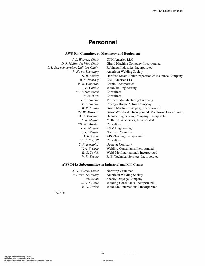
л®±²²»´
AWS D14 Committee on Machinery and Equipment
J. L. Warren, Chair CNH America LLCD. J. Malito, 1st Vice Chair Girard Machine Company, Incorporated
L. L. Schweinegruber, 2nd Vice Chair Robinson Industries, IncorporatedP. Howe, Secretary American Welding Society
D. B. Ashley Hartford Steam Boiler Inspection & Insurance CompanyB. K. Banzhaf CNH America LLC
P. W. Cameron Crenlo, IncorporatedP. Collins WeldCon Engineering
*R. T. Hemzacek ConsultantB. D. Horn Consultant
D. J. Landon Vermeer Manufacturing CompanyT. J. Landon Chicago Bridge & Iron CompanyM. R. Malito Girard Machine Company, Incorporated
*G. W. Martens Grove Worldwide, Incorporated, Manitowoc Crane GroupD. C. Martinez Danmar Engineering Company, Incorporated
A. R. Mellini Mellini & Associates, Incorporated*H. W. Mishler Consultant
R. E. Munson R&M EngineeringJ. G. Nelson Northrop GrummanA. R. Olsen ARO Testing, Incorporated
*P. J. Palzkill ConsultantC. R. Reynolds Deere & Company
W. A. Svekric Welding Consultants, IncorporatedE. G. Yevick Weld-Met International, IncorporatedV. R. Zegers R. E. Technical Services, Incorporated
AWS D14A Subcommittee on Industrial and Mill Cranes
J. G. Nelson, Chair Northrop GrummanP. Howe, Secretary American Welding Society
*L. Seum Sheedy Drayage CompanyW. A. Svekric Welding Consultants, IncorporatedE. G. Yevick Weld-Met International, Incorporated
*Advisor
ßÉÍ ÜïìòïñÜïìòïÓæîððë
ݱ°§®·¹¸¬ ß³»®·½¿² É»´¼·²¹ ͱ½·»¬§ Ю±ª·¼»¼ ¾§ ×ØÍ «²¼»® ´·½»²» ©·¬¸ ßÉÍ
Ò±¬ º±® λ¿´»Ò± ®»°®±¼«½¬·±² ±® ²»¬©±®µ·²¹ °»®³·¬¬»¼ ©·¬¸±«¬ ´·½»²» º®±³ ×ØÍ
óóÀôôÀôôÀóÀóÀôôÀôôÀôÀôôÀóóó

iv
This page is intentionally blank.
ßÉÍ ÜïìòïñÜïìòïÓæîððë
ݱ°§®·¹¸¬ ß³»®·½¿² É»´¼·²¹ ͱ½·»¬§ Ю±ª·¼»¼ ¾§ ×ØÍ «²¼»® ´·½»²» ©·¬¸ ßÉÍ
Ò±¬ º±® λ¿´»Ò± ®»°®±¼«½¬·±² ±® ²»¬©±®µ·²¹ °»®³·¬¬»¼ ©·¬¸±«¬ ´·½»²» º®±³ ×ØÍ
óóÀôôÀôôÀóÀóÀôôÀôôÀôÀôôÀóóó

v
Ú±®»©±®¼
(This Foreword is not a part of AWS D14.1/D14.1M:2005, Specification for Welding of Industrial and Mill Cranesand Other Material Handling Equipment, but is included for informational purposes only.)
This specification was prepared for the overhead crane and material handling industries to continue the advancementof welding and to increase product reliability. This 4th edition provides revisions to ANSI/AWS D14.1-97, Specificationfor Welding of Industrial and Mill Cranes and Other Material Handling Equipment, under the direction of the AWSMachinery and Equipment Committee.
The participating committee, representing manufacturers, users, and government, joined in the preparation of thisdocument. It will provide all concerned, including the general public, with high quality, reliable products and aneconomical approach to production, consistent with the industry�s capabilities.
This specification will be reviewed periodically to assure its success in serving all parties concerned with its provi-sions. Revisions will be issued when warranted.
Comments and suggestions for the improvement of this standard are welcome. They should be sent to the Secretary,AWS D14 Committee on Machinery and Equipment, American Welding Society, 550 N.W. LeJeune Road, Miami, FL33126.
Official interpretations of any of the technical requirements of this standard may only be obtained by sending arequest, in writing, to the Managing Director, Technical Services Division, American Welding Society. A formal replywill be issued after it has been reviewed by the appropriate personnel following established procedures (see Annex C).
ßÉÍ ÜïìòïñÜïìòïÓæîððë
ݱ°§®·¹¸¬ ß³»®·½¿² É»´¼·²¹ ͱ½·»¬§ Ю±ª·¼»¼ ¾§ ×ØÍ «²¼»® ´·½»²» ©·¬¸ ßÉÍ
Ò±¬ º±® λ¿´»Ò± ®»°®±¼«½¬·±² ±® ²»¬©±®µ·²¹ °»®³·¬¬»¼ ©·¬¸±«¬ ´·½»²» º®±³ ×ØÍ
óóÀôôÀôôÀóÀóÀôôÀôôÀôÀôôÀóóó

vi
This page is intentionally blank.
ßÉÍ ÜïìòïñÜïìòïÓæîððë
ݱ°§®·¹¸¬ ß³»®·½¿² É»´¼·²¹ ͱ½·»¬§ Ю±ª·¼»¼ ¾§ ×ØÍ «²¼»® ´·½»²» ©·¬¸ ßÉÍ
Ò±¬ º±® λ¿´»Ò± ®»°®±¼«½¬·±² ±® ²»¬©±®µ·²¹ °»®³·¬¬»¼ ©·¬¸±«¬ ´·½»²» º®±³ ×ØÍ
óóÀôôÀôôÀóÀóÀôôÀôôÀôÀôôÀóóó
vii
Ì¿¾´» ±º ݱ²¬»²¬
п¹» Ò±ò
Personnel .................................................................................................................................................................... iiiForeword ......................................................................................................................................................................vList of Tables ............................................................................................................................................................ viiiList of Figures........................................................................................................................................................... viii
1. Scope and General Provisions...............................................................................................................................11.1 Scope .........................................................................................................................................................11.2 General Provisions ....................................................................................................................................1
2. Normative References ...........................................................................................................................................22.1 American Welding Society (AWS) Standards ..........................................................................................22.2 American Society of Mechanical Engineers (ASME) Standards..............................................................22.3 American Society for Testing and Materials (ASTM) Standards .............................................................22.4 American Society for Nondestructive Testing (ASNT) Standards ...........................................................2
3. Definitions.............................................................................................................................................................3
4. Base Metals ...........................................................................................................................................................34.1 Specifications ............................................................................................................................................34.2 Proprietary Base Metals ............................................................................................................................34.3 Tensile and Yield Strengths of a Base Metal ............................................................................................34.4 Weldability ................................................................................................................................................34.5 Quenched and Tempered Steels ................................................................................................................34.6 Nonferrous Metals.....................................................................................................................................3
5. Allowable Stresses ................................................................................................................................................75.1 General ......................................................................................................................................................75.2 Fatigue.......................................................................................................................................................7
6. Weld Joint Design .................................................................................................................................................76.1 General Requirements ...............................................................................................................................76.2 Groove Welds............................................................................................................................................76.3 Intermittent Groove Welds........................................................................................................................76.4 Fillet Welds ...............................................................................................................................................76.5 Intermittent Fillet Welds ...........................................................................................................................96.6 Staggered Intermittent Fillet Welds ..........................................................................................................96.7 Plug and Slot Welds ................................................................................................................................176.8 Suggested Classification of Welded Joints .............................................................................................186.9 Weld Joint Classes ..................................................................................................................................206.10 Joint Qualification ...................................................................................................................................206.11 Transition of Thicknesses or Widths at Butt Joints.................................................................................206.12 Material for Joint Extensions, Backing, and Spacers..............................................................................206.13 Dimensional Tolerances..........................................................................................................................226.14 Lap Joints ................................................................................................................................................226.15 Corner and T-Joints.................................................................................................................................236.16 Welds in Combination with Rivets and Bolts .........................................................................................236.17 Eccentricity of Connections ....................................................................................................................23
ßÉÍ ÜïìòïñÜïìòïÓæîððë
ݱ°§®·¹¸¬ ß³»®·½¿² É»´¼·²¹ ͱ½·»¬§ Ю±ª·¼»¼ ¾§ ×ØÍ «²¼»® ´·½»²» ©·¬¸ ßÉÍ
Ò±¬ º±® λ¿´»Ò± ®»°®±¼«½¬·±² ±® ²»¬©±®µ·²¹ °»®³·¬¬»¼ ©·¬¸±«¬ ´·½»²» º®±³ ×ØÍ
óóÀôôÀôôÀóÀóÀôôÀôôÀôÀôôÀóóó

viii
п¹» Ò±ò
7. Workmanship ......................................................................................................................................................237.1 General ....................................................................................................................................................237.2 Preparation of the Base Metal .................................................................................................................237.3 Visual Inspection and Repair of Plate and Wrought Steel Products .......................................................247.4 Assembly.................................................................................................................................................257.5 Control of Distortion and Shrinkage Stresses .........................................................................................277.6 Stress Relief.............................................................................................................................................277.7 Vibratory Conditioning ...........................................................................................................................277.8 Peening ....................................................................................................................................................28
8. Processes and Filler Metals .................................................................................................................................288.1 General ....................................................................................................................................................288.2 Shielded Metal Arc Welding (SMAW)...................................................................................................298.3 Submerged Arc Welding (SAW) ............................................................................................................328.4 Gas Metal Arc Welding (GMAW) and Flux Cored Arc Welding (FCAW)...........................................348.5 Electroslag Welding (ESW) and Electrogas Welding (EGW)................................................................34
9. Qualification........................................................................................................................................................36Part A�General Requirements...........................................................................................................................369.1 Approved Procedures ..............................................................................................................................369.2 Other Procedures .....................................................................................................................................379.3 Welders, Welding Operators, and Tack Welders ....................................................................................379.4 Qualification Responsibility....................................................................................................................37Part B�Procedure Qualification........................................................................................................................379.5 Qualification of Welding Procedures ......................................................................................................379.6 Types of Tests and Purposes ...................................................................................................................419.7 Base Metal...............................................................................................................................................419.8 Position of Test Welds ............................................................................................................................419.9 Joint Welding Procedure .........................................................................................................................429.10 Test Specimens........................................................................................................................................429.11 Method of Testing Specimens.................................................................................................................499.12 Test Results Required..............................................................................................................................529.13 Records....................................................................................................................................................559.14 Retests .....................................................................................................................................................55Part C�Welder Qualification.............................................................................................................................559.15 General ....................................................................................................................................................559.16 Limitations ..............................................................................................................................................559.17 Qualification Tests Required...................................................................................................................569.18 Groove Weld Plate Qualification Test for Plate of Unlimited Thickness...............................................569.19 Groove Weld Plate Qualification Test for Plate of Limited Thickness ..................................................569.20 Groove Weld Qualification Test for Butt Joints in Pipe or Tubing ........................................................569.21 Groove Weld Qualification Test for T-, Y-, and K-Connections on Pipe or Tubing..............................569.22 Fillet Weld Qualification Test.................................................................................................................639.23 Position of Test Welds ............................................................................................................................639.24 Base Metal...............................................................................................................................................659.25 Joint Welding Procedure .........................................................................................................................659.26 Test Specimens........................................................................................................................................659.27 Method of Testing Specimens.................................................................................................................659.28 Test Results Required..............................................................................................................................669.29 Retests .....................................................................................................................................................679.30 Period of Effectiveness............................................................................................................................689.31 Records....................................................................................................................................................689.32 Workmanship Qualification ....................................................................................................................68
ßÉÍ ÜïìòïñÜïìòïÓæîððë
ݱ°§®·¹¸¬ ß³»®·½¿² É»´¼·²¹ ͱ½·»¬§ Ю±ª·¼»¼ ¾§ ×ØÍ «²¼»® ´·½»²» ©·¬¸ ßÉÍ
Ò±¬ º±® λ¿´»Ò± ®»°®±¼«½¬·±² ±® ²»¬©±®µ·²¹ °»®³·¬¬»¼ ©·¬¸±«¬ ´·½»²» º®±³ ×ØÍ
óóÀôôÀôôÀóÀóÀôôÀôôÀôÀôôÀóóó

ix
п¹» Ò±ò
Part D�Welding Operator Qualification...........................................................................................................709.33 General ....................................................................................................................................................709.34 Limitations ..............................................................................................................................................709.35 Qualification Tests Required...................................................................................................................709.36 Base Metal...............................................................................................................................................719.37 Joint Welding Procedure .........................................................................................................................719.38 Test Specimens........................................................................................................................................729.39 Method of Testing Specimens.................................................................................................................729.40 Test Results Required..............................................................................................................................759.41 Retests .....................................................................................................................................................759.42 Period of Effectiveness............................................................................................................................759.43 Records....................................................................................................................................................75Part E�Qualification of Tack Welders ..............................................................................................................759.44 General ....................................................................................................................................................759.45 Limitations ..............................................................................................................................................759.46 Qualification Tests Required...................................................................................................................759.47 Base Metal...............................................................................................................................................759.48 Test Specimen .........................................................................................................................................769.49 Method of Testing ...................................................................................................................................769.50 Test Results Required..............................................................................................................................769.51 Retests .....................................................................................................................................................769.52 Period of Effectiveness............................................................................................................................769.53 Records....................................................................................................................................................76
10. Weld Quality and Inspection...............................................................................................................................7710.1 General ....................................................................................................................................................7710.2 Owner�s Representative ..........................................................................................................................7710.3 Inspection of Welding Procedure Qualifications ....................................................................................7710.4 Inspection of Welder, Tack Welder, and Welding Operator Qualifications ...........................................7710.5 Inspection of Work and Records.............................................................................................................7710.6 Visual Examination .................................................................................................................................7810.7 Welding Profiles......................................................................................................................................7810.8 Nondestructive Examination ...................................................................................................................7810.9 Radiographic Examination of Welds ......................................................................................................8010.10 Radiographic Procedure ..........................................................................................................................8010.11 Acceptability of Radiographed Welds ....................................................................................................8110.12 Examination, Report, and Disposition of Radiographs...........................................................................8110.13 Ultrasonic Examination of Welds ...........................................................................................................8210.14 Ultrasonic Testing Equipment and Calibration.......................................................................................8310.15 Ultrasonic Testing Procedure, Acceptance Criteria, and Reports ...........................................................8710.16 Magnetic Particle Examination of Welds................................................................................................9210.17 Liquid Penetrant Examination of Welds .................................................................................................92
11. Field Weld Repair and Modification...................................................................................................................9211.1 General ....................................................................................................................................................9211.2 Field Repair�Manufacturer�s Responsibility ........................................................................................9211.3 Field Repair�Owner�s Responsibility ...................................................................................................93
12. Repair and Correction of Defects........................................................................................................................9312.1 Weld Repairs ...........................................................................................................................................9312.2 Base Metal Repairs..................................................................................................................................9312.3 Removal of Defective Areas ...................................................................................................................9412.4 Distortion and Camber ............................................................................................................................9412.5 Correction of Improperly Fitted and Welded Members..........................................................................94
ßÉÍ ÜïìòïñÜïìòïÓæîððë
ݱ°§®·¹¸¬ ß³»®·½¿² É»´¼·²¹ ͱ½·»¬§ Ю±ª·¼»¼ ¾§ ×ØÍ «²¼»® ´·½»²» ©·¬¸ ßÉÍ
Ò±¬ º±® λ¿´»Ò± ®»°®±¼«½¬·±² ±® ²»¬©±®µ·²¹ °»®³·¬¬»¼ ©·¬¸±«¬ ´·½»²» º®±³ ×ØÍ
óóÀôôÀôôÀóÀóÀôôÀôôÀôÀôôÀóóó
x
п¹» Ò±ò
Mandatory Annex .......................................................................................................................................................95Annex I�Prequalified Weld Joints ............................................................................................................................95
Nonmandatory Annexes............................................................................................................................................119Annex A�Suggested Forms .....................................................................................................................................119Annex B�Examples of Weld Quality Requirements ................................................................................................129Annex C�Guidelines for Preparation of Technical Inquiries for AWS Technical Committees ..............................131Annex D�Bibliography............................................................................................................................................133
List of AWS Documents on Machinery and Equipment............................................................................................135
ßÉÍ ÜïìòïñÜïìòïÓæîððë
ݱ°§®·¹¸¬ ß³»®·½¿² É»´¼·²¹ ͱ½·»¬§ Ю±ª·¼»¼ ¾§ ×ØÍ «²¼»® ´·½»²» ©·¬¸ ßÉÍ
Ò±¬ º±® λ¿´»Ò± ®»°®±¼«½¬·±² ±® ²»¬©±®µ·²¹ °»®³·¬¬»¼ ©·¬¸±«¬ ´·½»²» º®±³ ×ØÍ
óóÀôôÀôôÀóÀóÀôôÀôôÀôÀôôÀóóó
xi
Ô·¬ ±º Ì¿¾´»
Ì¿¾´» п¹» Ò±ò
1 Weldability Classification of Steels ...............................................................................................................42 Allowable Stress in Weld Metal ....................................................................................................................83 Allowable Stress Range .................................................................................................................................94 Stress Categories to Determine Allowable Stress Range.............................................................................105 Minimum Effective Throat for Partial Joint Penetration Groove Welds .....................................................156 Minimum Fillet Weld Size...........................................................................................................................177 Limits on Acceptability and Repair of Edge Discontinuities in Cut Surfaces.............................................258 Tolerances for Groove Weld Joint Preparations for Arc Welding...............................................................269 Matching Filler Metal Requirements ...........................................................................................................30
10 Minimum Preheat and Interpass Temperatures ...........................................................................................3111 Impact Property Requirements at 0°F [�18°C] for Electrogas and Electroslag Welds ...............................3512 All-Weld-Metal Tension Test Requirements for Electrogas and Electroslag Welds ..................................3613 Procedure Qualification�Type and Position Limitations...........................................................................4214 Number and Type of Test Specimens and Range of Thickness Qualified�Procedure
Qualification; Complete Joint Penetration Groove Welds...........................................................................4615 Acceptable Reinforcement on Groove Welds in Pipe and Tubing ..............................................................5516 SMAW Electrode Groups ............................................................................................................................5517 Number and Type of Test Specimens and Range of Thickness Qualified�Welder and
Welding Operator Qualification...................................................................................................................5718 Welder Qualification�Type and Position Limitations ...............................................................................5819 Penetrameter Requirements .........................................................................................................................8120 Ultrasonic Testing Angle .............................................................................................................................8921 Ultrasonic Acceptance and Rejection Criteria .............................................................................................91
ßÉÍ ÜïìòïñÜïìòïÓæîððë
ݱ°§®·¹¸¬ ß³»®·½¿² É»´¼·²¹ ͱ½·»¬§ Ю±ª·¼»¼ ¾§ ×ØÍ «²¼»® ´·½»²» ©·¬¸ ßÉÍ
Ò±¬ º±® λ¿´»Ò± ®»°®±¼«½¬·±² ±® ²»¬©±®µ·²¹ °»®³·¬¬»¼ ©·¬¸±«¬ ´·½»²» º®±³ ×ØÍ
óóÀôôÀôôÀóÀóÀôôÀôôÀôÀôôÀóóó

xii
Ô·¬ ±º Ú·¹«®»
Ú·¹«®» п¹» Ò±ò
1 Illustrative Examples for Table 4.................................................................................................................132 Fillet and Combined Weld Dimension.........................................................................................................153 Size and Effective Throat Measurements for Fillet and Partial Penetration Groove Welds
with Reinforcing Fillet Welds......................................................................................................................164 Staggered Intermittent Fillet Weld...............................................................................................................175 Classification of Welded Joints....................................................................................................................186 Transition of Butt Joints in Parts Having Unequal Thickness .....................................................................217 Transition of Width at Butt Joints of Parts Having Unequal Width ............................................................228 Edge Discontinuities in Cut Material...........................................................................................................259 Pneumatic Hammer Peening........................................................................................................................29
10 Unacceptable Submerged Arc Weld Pass where the Depth and Width Exceed the Face Width ................3211 Positions of Test Plates for Groove Welds ..................................................................................................4312 Positions of Test Pipe or Tubing for Groove Welds ....................................................................................4413 Positions of Test Plates for Fillet Welds......................................................................................................4514A Location of Test Specimens on Welded Test Pipe 2 in. [50 mm] or 3 in. [75 mm] in Diameter ................4714B Location of Test Specimens on Welded Test Pipe 6 in. [150 mm] or 8 in. [200 mm] in Diameter ............4714C Location of Test Specimens on Welded Test Plate�Electroslag and Electrogas Welding�
Procedure Qualification ...............................................................................................................................4814D Location of Test Specimens on Welded Test Plate Over 3/8 in. [10 mm] Thick�Procedure
Qualification.................................................................................................................................................4914E Location of Test Specimens on Welded Test Plate 3/8 in. [10 mm] Thick and Under�
Procedure Qualification ...............................................................................................................................5015A Reduced-Section Tension Specimens ..........................................................................................................5115B All-Weld-Metal Tension Specimens............................................................................................................5215C Face- and Root-Bend Specimens .................................................................................................................5315D Side-Bend Specimens ..................................................................................................................................5416 Fillet Weld Soundness Test for Procedure Qualification.............................................................................5417A Test Plate for Unlimited Thickness�Welder Qualification........................................................................5917B Optional Test Plate for Unlimited Thickness, Horizontal Position�Welder Qualification........................5918A Test Plate for Limited Thickness, All Positions�Welder Qualification.....................................................6018B Optional Test Plate for Limited Thickness, Horizontal Position�Welder Qualification ...........................6019A Pipe Test Butt Joint without Backing�Welder Qualification.....................................................................6119B Pipe Test Butt Joint with Backing�Welder Qualification..........................................................................6120 Test Joint for T-, Y-, and K-Connections on Pipe or Tubing�Welder Qualification ................................6121 Location of Test Specimens on Welded Test Pipe�Welder Qualification.................................................6222 Fillet Weld Break and Macroetch Test Plate�Welder Qualification, Option 1 .........................................6323 Fillet Weld Root-Bend Test Plate�Welder Qualification, Option 2 ..........................................................6424A Guided-Bend Test Jig�Standard Design ....................................................................................................6624B Alternative Guided-Bend Test Jig�Wraparound Design ...........................................................................6724C Alternative Guided-Bend Test Jig�Roller-Equipped Design for Bottom Ejection of Test Specimens .....6825 Examples of Workmanship Samples ...........................................................................................................6926 Test Plate for Unlimited Thickness�Welding Operator Qualification.......................................................7127 Butt Joint for Electroslag and Electrogas�Welding Operator Qualification..............................................7228 Fillet Weld Break and Macroetch Test Plate�Welding Operator Qualification, Option 1 ........................7329 Fillet Weld Root-Bend Test Plate�Welding Operator Qualification, Option 2 .........................................74
ßÉÍ ÜïìòïñÜïìòïÓæîððë
ݱ°§®·¹¸¬ ß³»®·½¿² É»´¼·²¹ ͱ½·»¬§ Ю±ª·¼»¼ ¾§ ×ØÍ «²¼»® ´·½»²» ©·¬¸ ßÉÍ
Ò±¬ º±® λ¿´»Ò± ®»°®±¼«½¬·±² ±® ²»¬©±®µ·²¹ °»®³·¬¬»¼ ©·¬¸±«¬ ´·½»²» º®±³ ×ØÍ
óóÀôôÀôôÀóÀóÀôôÀôôÀôÀôôÀóóó
xiii
Ú·¹«®» п¹» Ò±ò
30 Fillet Weld Break Specimen�Tack Welder Qualification .........................................................................7631 Method of Fracturing Fillet Weld Break Specimen�Tack Welder Qualification ......................................7632 Acceptable and Unacceptable Weld Profiles ...............................................................................................7933 Weld Quality Requirements for Discontinuities Occurring in Welds (Limitation of Porosity and
Fusion-Type Discontinuities).......................................................................................................................8234A RC Resolution Reference Block (U.S. Units)..............................................................................................8434B RC Resolution Reference Block (SI Units) .................................................................................................8534C Typical Transducer Positions.......................................................................................................................8635 Plan View of UT Scanning Patterns ............................................................................................................88I.1 Prequalified Complete Joint Penetration Groove Welded Joints.................................................................95I.2 Prequalified Partial Joint Penetration Groove Welded Joints ....................................................................109A.1 Sample Form E1, Front ..............................................................................................................................120A.2 Sample Form E1, Back ..............................................................................................................................121A.3 Sample Form E2.........................................................................................................................................122A.4 Sample Form E3.........................................................................................................................................123A.5 Sample Form E4.........................................................................................................................................124A.6 Sample Form E5.........................................................................................................................................125A.7 Sample Form E6.........................................................................................................................................126A.8 Sample Form E7.........................................................................................................................................128B.1 Examples of Weld Quality Requirements..................................................................................................129
ßÉÍ ÜïìòïñÜïìòïÓæîððë
ݱ°§®·¹¸¬ ß³»®·½¿² É»´¼·²¹ ͱ½·»¬§ Ю±ª·¼»¼ ¾§ ×ØÍ «²¼»® ´·½»²» ©·¬¸ ßÉÍ
Ò±¬ º±® λ¿´»Ò± ®»°®±¼«½¬·±² ±® ²»¬©±®µ·²¹ °»®³·¬¬»¼ ©·¬¸±«¬ ´·½»²» º®±³ ×ØÍ
óóÀôôÀôôÀóÀóÀôôÀôôÀôÀôôÀóóó

xiv
This page is intentionally blank.
ßÉÍ ÜïìòïñÜïìòïÓæîððë
ݱ°§®·¹¸¬ ß³»®·½¿² É»´¼·²¹ ͱ½·»¬§ Ю±ª·¼»¼ ¾§ ×ØÍ «²¼»® ´·½»²» ©·¬¸ ßÉÍ
Ò±¬ º±® λ¿´»Ò± ®»°®±¼«½¬·±² ±® ²»¬©±®µ·²¹ °»®³·¬¬»¼ ©·¬¸±«¬ ´·½»²» º®±³ ×ØÍ
óóÀôôÀôôÀóÀóÀôôÀôôÀôÀôôÀóóó
ßÉÍ ÜïìòïñÜïìòïÓæîððë
1
1. Scope and General Provisions1.1 Scope. This specification applies to the welding of allprincipal structural weldments and all primary weldsused in the manufacture of cranes for industrial, mill,power house, and nuclear facilities. Furthermore, thespecification applies to other overhead material handlingmachinery and equipment that support and transportloads within the design rating, vertically or horizontally,during normal operations, and, when agreed uponbetween the Owner and Manufacturer, to loading causedby abnormal operations or environmental events, such asseismic loading.
Secondary welds that will be subjected to tensilestresses of less than 5000 psi [34.5 MPa] need only meetthe requirements of Section 7, Workmanship, and Sec-tion 10, Weld Quality and Inspection. The engineeringdrawings shall specify the joint detail, type, and size ofweld. This specification is not intended for application toconstruction- or crawler-type cranes. For the welding ofrails, refer to AWS D15.2, Recommended Practice forthe Welding of Rails and Related Rail Components forUse by Rail Vehicles.
All provisions of this specification are equally appli-cable to the strengthening and repairing of existingoverhead cranes and material handling equipment asdescribed above.
This specification makes use of both U.S. CustomaryUnits and the International System of Units (SI). Themeasurements may not be exact equivalents; thereforeeach system shall be used independently of the otherwithout combining in any way. The specification withthe designation D14.1 uses U.S. Customary Units. Thespecification D14.1M uses SI Units. The latter are shownin appropriate columns in tables and figures or withinbrackets [ ]. Detailed dimensions on figures are ininches. A separate tabular form that relates the U.S.Customary Units with SI Units may be used in tables andfigures.
Safety and health issues and concerns are beyond thescope of this standard, and therefore are not fully
addressed herein. Safety and health information is avail-able from other sources, including, but not limited to,ANSI Z49.1, Safety in Welding, Cutting, and Allied Pro-cesses and applicable federal and state regulations. Someother sources of safety and health information can befound in Annex D.
1.2 General Provisions. The Manufacturer�s1 adherenceto this specification shall include responsibility for thefollowing:
(1) Welding, as defined in the Scope, in accordancewith this specification;
(2) Producing the welds designated on the drawingsby appropriate welding symbols and notes containingsufficient detail to show joint preparations compatiblewith the designated welding processes;
(3) Providing written welding procedures;(4) Recording results of all procedure and welder
qualification tests;(5) Controlling the use of designated base metals and
consumables; and(6) Inspecting the welds to the requirements of this
specification.
1.2.1 Acceptance. Acceptance shall be as agreedupon between the Manufacturer and the Owner (pur-chaser). The fundamental premise of this specification isto provide general stipulations applicable to most situa-tions. Acceptance criteria for production welds differentfrom those stated in this specification may be used for aparticular application, provided they are suitably docu-mented by the proposer and approved by the Engineer.These alternate acceptance criteria can be based uponevaluation of suitability for service using past experi-ence, experimental evidence or engineering analysisconsidering material type, service-load effects, and envi-ronmental factors.
1. Manufacturer refers to the organization responsible for theperformance of the work covered by this specification (see def-inition in Section 3).
Í°»½·º·½¿¬·±² º±® É»´¼·²¹ ±º ײ¼«¬®·¿´ ¿²¼ Ó·´´ Ý®¿²»¿²¼ Ѭ¸»® Ó¿¬»®·¿´ Ø¿²¼´·²¹ Û¯«·°³»²¬
ݱ°§®·¹¸¬ ß³»®·½¿² É»´¼·²¹ ͱ½·»¬§ Ю±ª·¼»¼ ¾§ ×ØÍ «²¼»® ´·½»²» ©·¬¸ ßÉÍ
Ò±¬ º±® λ¿´»Ò± ®»°®±¼«½¬·±² ±® ²»¬©±®µ·²¹ °»®³·¬¬»¼ ©·¬¸±«¬ ´·½»²» º®±³ ×ØÍ
óóÀôôÀôôÀóÀóÀôôÀôôÀôÀôôÀóóó
ßÉÍ ÜïìòïñÜïìòïÓæîððë
2
1.2.2 Welding Symbols. Welding symbols used onshop drawings shall be those shown in AWS A2.4, Stan-dard Symbols for Welding, Brazing, and NondestructiveExamination. Special requirements shall be fullyexplained by added notes or details.
1.2.3 Mechanical Testing of Welds. Methods used inthe mechanical testing of welds shall be those describedin AWS B4.0 or B4.0M, Standard Methods for Mechani-cal Testing of Welds. When there is a conflict betweenthis specification and AWS B4.0 or B4.0M, the pro-visions of this specification shall govern.
1.2.4 Filler Metal Specifications. All welding con-sumables shall meet the requirements of the applicableAWS filler metal specifications, except for specificrequirements of this specification.
2. Normative ReferencesThe following standards contain provisions which,
through reference in this text, constitute provisions ofthis AWS standard. For undated references, the latestedition of the referenced standard shall apply. For datedreferences, subsequent amendments to, or revisions of,any of these publications do not apply.
2.1 American Welding Society (AWS) Standards2
(1) AWS A2.4, Standard Symbols for Welding,Brazing, and Nondestructive Examination
(2) AWS A3.0, Standard Welding Terms and Definitions(3) AWS A5.01, Filler Metal Procurement Guidelines(4) AWS A5.1, Specification for Carbon Steel Elec-
trodes for Shielded Metal Arc Welding(5) AWS A5.5, Specification for Low-Alloy Steel
Electrodes for Shielded Metal Arc Welding(6) AWS A5.17, Specification for Carbon Steel Elec-
trodes and Fluxes for Submerged Arc Welding(7) AWS A5.18, Specification for Carbon Steel Elec-
trodes and Rods for Gas Shielded Arc Welding(8) AWS A5.20, Specification for Carbon Steel Elec-
trodes for Flux Cored Arc Welding(9) AWS A5.23, Specification for Low Alloy Steel
Electrodes and Fluxes for Submerged Arc Welding(10) AWS A5.25, Specification for Carbon and
Low Alloy Steel Electrodes and Fluxes for ElectroslagWelding
(11) AWS A5.26, Specification for Carbon and LowAlloy Steel Electrodes for Electrogas Welding
(12) AWS A5.28, Specification for Low-Alloy SteelFiller Metals for Gas Shielded Arc Welding
2. AWS standards are published by the American WeldingSociety, 550 N.W. LeJeune Road, Miami, FL 33126.
(13) AWS A5.29, Specification for Low Alloy SteelElectrodes for Flux Cored Arc Welding
(14) AWS A5.32, Specification for Welding ShieldingGases
(15) AWS B2.1, Specification for Welding Procedureand Performance Qualification
(16) AWS B4.0, Standard Methods for MechanicalTesting of Welds (U.S. Customary Units only)
(17) AWS B4.0M, Standard Methods for MechanicalTesting of Welds (SI Units only)
(18) AWS C4.1, Oxygen Cutting Surface RoughnessGauge
(19) AWS QC1, Standard for AWS Certification ofWelding Inspectors
2.2 American Society of Mechanical Engineers(ASME) Standards3
(1) ASME B 46.1, Surface Texture (Surface Rough-ness, Waviness, and Lay)
2.3 American Society for Testing and Materials(ASTM) Standards4
(1) ASTM E 23, Test Methods for Notched BarImpact Testing of Metallic Materials
(2) ASTM E 94, Standard Guide for RadiographicExamination
(3) ASTM E 164, Practice for Ultrasonic ContactExamination of Weldments
(4) ASTM E 165, Test Method for Liquid PenetrantExamination
(5) ASTM E 317, Practice for Evaluating PerformanceCharacteristics of Ultrasonic Pulse-Echo Testing Systemswithout the Use of Electronic Measurement Instruments
(6) ASTM A 435, Specification for Straight-BeamUltrasonic Examination of Steel Plates
(7) ASTM E 709, Guide for Magnetic ParticleExamination
(8) ASTM E 1316, Standard Terminology for Non-destructive Examinations
2.4 American Society for Nondestructive Testing(ASNT) Standards5
(1) SNT-TC-1A, Recommended Practice No. SNT-TC-1A
3. ASME standards are published by the American Society ofMechanical Engineers, 3 Park Avenue, New York, NY 10017.4. ASTM standards are published by the American Society forTesting and Materials, 100 Barr Harbor Drive, West Consho-hocken, PA 19428-2959.5. ASNT standards are published by the American Society forNondestructive Testing, Inc., P.O. Box 28518, 1711 ArlingateLane, Columbus, OH 43228-0518.
ݱ°§®·¹¸¬ ß³»®·½¿² É»´¼·²¹ ͱ½·»¬§ Ю±ª·¼»¼ ¾§ ×ØÍ «²¼»® ´·½»²» ©·¬¸ ßÉÍ
Ò±¬ º±® λ¿´»Ò± ®»°®±¼«½¬·±² ±® ²»¬©±®µ·²¹ °»®³·¬¬»¼ ©·¬¸±«¬ ´·½»²» º®±³ ×ØÍ
óóÀôôÀôôÀóÀóÀôôÀôôÀôÀôôÀóóó
ßÉÍ ÜïìòïñÜïìòïÓæîððë
3
3. Definitions
The terms that follow are defined for the purposes ofthis specification. Other terms used in this specificationare defined in AWS A3.0, Standard Welding Terms andDefinitions.
Engineer. The responsible technical authority.
Manufacturer. The organization responsible for the per-formance of the work covered by this specification.
Owner. The person, company, or agency that purchasesthe equipment.
principal structural weldments. Those weldments thatcarry the main working loads during normal operations.
primary welds. Welds, the failure of which would resultin (1) a carried load being dropped in excess of 4 in.[100 mm] or (2) an increase of stress beyond theallowable stress limits, as defined in Section 5,Allowable Stresses, in other welds or base metal. Anywelds subject to only compressive stresses are notconsidered primary.
secondary welds. Welds not covered by the requirementsof primary welds; secondary welds shall be noted assuch on the drawings. Secondary welds only need tomeet the requirements of Section 7, Workmanship,and Section 10, Weld Quality and Inspection.
tensile strength of the weld metal. The minimum tensilestrength specified for the filler metal classification aspublished in the applicable filler metal specification.
4. Base Metals
4.1 Specifications. All ferrous and nonferrous metals,structural steel, steel castings, forgings, and any othermetals used in the fabrication by welding of all compo-nents for overhead material handling machinery andequipment shall be identified by a specification. Com-mon industry-wide specifications from organizationssuch as the American Society for Testing and Materials(ASTM), the American Iron and Steel Institute (AISI),the American Petroleum Institute (API), and the Societyof Automotive Engineers (SAE), or written proprietaryspecifications developed by an individual equipmentmanufacturer, may be used.
4.2 Proprietary Base Metals. The weldability of and theprocedure for welding (1) base metals covered by aspecific equipment manufacturer�s proprietary specifica-
tion, (2) steels not listed in Table 1, or (3) base metals notcovered by accepted national specifications, shall beestablished by qualification, except as provided for in4.4.
4.3 Tensile and Yield Strengths of a Base Metal. Theminimum specified tensile and yield strengths for basemetals are listed in Table 1. When Table 1 or the basemetal specification does not establish the minimum ten-sile and yield strengths for acceptance, the Manufacturershall establish the minimum tensile and yield strengthsfor design purposes. The documentation may be in theform of references to published data or compilations oftest data. In the establishment of minimum tensile andyield strengths for design purposes, due regard shall bemade for size effects, thermal or mechanical treatments,and the effect of the welding process on the base materialin the heat-affected zone (HAZ).
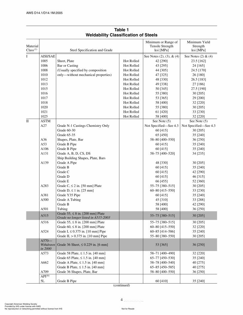
4.4 Weldability. Steel base metals listed in Table 1(including combinations thereof) shall be consideredweldable without separate qualification, except basemetals with a minimum yield strength of 90 ksi[620 MPa] or higher (see 9.1.1). The steels listed inTable 1 are classified into groups according to the degreeof difficulty encountered during welding related tochemical composition, rolling condition, or heat treat-ment. Steels in the higher classifications require greaterprecautions during welding, such as preheat, limited heatinput, or other precautions to ensure sound weldments.When welding combinations of these steels, precautionsrelated to the steel with the higher classification numbershould be observed.
4.5 Quenched and Tempered Steels. Quenched andtempered steels may be used where design and other fac-tors permit or require them. Their use shall be compati-ble with their mechanical properties and the designrequirements as documented by the equipment manufac-turer. Documentation may be in either of two forms:
(1) An acceptable service history proving reliability,or
(2) Welding procedure development and qualifica-tion data establishing the expected service life of thesteel according to accepted engineering criteria for theapplication.
4.6 Nonferrous Metals. Nonferrous metals that meet therequirements of an accepted specification, as describedin 4.1, may be used in the fabrication of components bywelding. Proper documentation in the form of qualifiedwelding procedures and other experimental data shall beprovided by the Manufacturer using such metals.
ݱ°§®·¹¸¬ ß³»®·½¿² É»´¼·²¹ ͱ½·»¬§ Ю±ª·¼»¼ ¾§ ×ØÍ «²¼»® ´·½»²» ©·¬¸ ßÉÍ
Ò±¬ º±® λ¿´»Ò± ®»°®±¼«½¬·±² ±® ²»¬©±®µ·²¹ °»®³·¬¬»¼ ©·¬¸±«¬ ´·½»²» º®±³ ×ØÍ
óóÀôôÀôôÀóÀóÀôôÀôôÀôÀôôÀóóó
ßÉÍ ÜïìòïñÜïìòïÓæîððë
4
Ì¿¾´» ïÉ»´¼¿¾·´·¬§ Ý´¿·º·½¿¬·±² ±º ͬ»»´
Material Class(1) Steel Specification and Grade
Minimum or Range of Tensile Strength
ksi [MPa]
Minimum YieldStrength
ksi [MPa]
I AISI/SAE See Notes (2), (3), & (4) See Notes (2) & (4)1005 Sheet, Plate Hot Rolled 42 [290] 23.5 [162]1006 Bar or Casting Hot Rolled 43 [295] 24 [165]1008 (Usually specified by composition Hot Rolled 44 [305] 24.5 [170]1010 only�without mechanical properties) Hot Rolled 47 [325] 26 [180]1012 Hot Rolled 48 [330] 26.5 [183]1013 Hot Rolled 49 [338] 27 [186]1015 Hot Rolled 50 [345] 27.5 [190]1016 Hot Rolled 55 [380] 30 [205]1017 Hot Rolled 53 [365] 29 [200]1018 Hot Rolled 58 [400] 32 [220]1020 Hot Rolled 55 [380] 30 [205]1021 Hot Rolled 61 [420] 33 [230]1025 Hot Rolled 58 [400] 32 [220]
II ASTM See Note (5) See Note (5)A27 Grade N-1 Castings Chemistry Only Not Specified�See 4.3 Not Specified�See 4.3
Grade 60-30 60 [415] 30 [205]Grade 65-35 65 [450] 35 [240]
A36 Shapes, Plate, Bar 58�80 [400�550] 36 [250]A53 Grade B Pipe 60 [415] 35 [240]A106 Grade B Pipe 60 [415] 35 [240]A131 Grade A, B, D, CS, DS 58�75 [400�520] 34 [235]
Ship Building Shapes, Plate, BarsA139 Grade A Pipe 48 [330] 30 [205]
Grade B 60 [415] 35 [240]Grade C 60 [415] 42 [290]Grade D 60 [415] 46 [315]Grade E 66 [455] 52 [360]
A283 Grade C, 2 in. [50 mm] Plate 55�75 [380�515] 30 [205]Grade D, 1 in. [25 mm] 60�80 [415�550] 33 [230]
A381 Grade Y35 Pipe 60 [415] 35 [240]A500 Grade A Tubing 45 [310] 33 [288]
Grade B 58 [400] 42 [290]A501 Tubing 58 [400] 36 [250]
A515 Grade 55, 8 in. [200 mm] PlateGrade no longer listed in A515-2003 55�75 [380�515] 30 [205]
A516 Grade 55, 8 in. [200 mm] Plate 55�75 [380�515] 30 [205]Grade 60, 8 in. [200 mm] Plate 60�80 [415�550] 32 [220]
A524 Grade I, 0.375 in. [10 mm] Pipe 60�85 [414�586] 35 [240]Grade II, > 0.375 in. [10 mm] Pipe 55�80 [380�550] 30 [205]
A570�Withdrawnin 2000
Grade 36 Sheet, 0.229 in. [6 mm] 53 [365] 36 [250]
A573 Grade 58 Plate, 1.5 in. [40 mm] 58�71 [400�490] 32 [220]Grade 65 Plate, 1.5 in. [40 mm] 65�77 [450�530] 35 [240]
A662 Grade A Plate, 1.5 in. [40 mm] 58�78 [400�540] 40 [275]Grade B Plate, 1.5 in. [40 mm] 65�85 [450�585] 40 [275]
A709 Grade 36 Shapes, Plate, Bar 58�80 [400�550] 36 [250]API(6)
5L Grade B Pipe 60 [410] 35 [240](continued)
ݱ°§®·¹¸¬ ß³»®·½¿² É»´¼·²¹ ͱ½·»¬§ Ю±ª·¼»¼ ¾§ ×ØÍ «²¼»® ´·½»²» ©·¬¸ ßÉÍ
Ò±¬ º±® λ¿´»Ò± ®»°®±¼«½¬·±² ±® ²»¬©±®µ·²¹ °»®³·¬¬»¼ ©·¬¸±«¬ ´·½»²» º®±³ ×ØÍ
óóÀôôÀôôÀóÀóÀôôÀôôÀôÀôôÀóóó
ßÉÍ ÜïìòïñÜïìòïÓæîððë
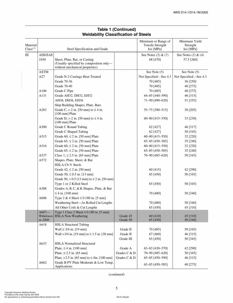
5
III AISI/SAE See Notes (2) & (7) See Notes (2) & (4)1030 Sheet, Plate, Bar, or Casting
(Usually specified by composition only�without mechanical properties)
68 [470] 37.5 [260]
ASTM See Note (5) See Note (5)A27 Grade N-2 Castings Heat Treated Not Specified�See 4.3 Not Specified�See 4.3
Grade 70-36 70 [485] 36 [250]Grade 70-40 70 [485] 40 [275]
A106 Grade C Pipe 70 [485] 40 [275]A131 Grade AH32, DH32, EH32 64�85 [440�590] 46 [315]
AH36, DH36, EH36 71�90 [490�620] 51 [355]Ship Building Shapes, Plate, Bars
A283 Grade C, > 2 in. [50 mm] to 4 in.[100 mm] Plate
55�75 [380�515] 30 [205]
Grade D, > 2 in. [50 mm] to 4 in.[100 mm] Plate
60�80 [415�550] 33 [230]
A500 Grade C Round Tubing 62 [427] 46 [317]Grade C Shaped Tubing 62 [427] 50 [345]
A515 Grade 60, 2 in. [50 mm] Plate 60�80 [415�550] 32 [220]Grade 65, 2 in. [50 mm] Plate 65�85 [450�585] 35 [240]
A516 Grade 60, 2 in. [50 mm] Plate 60�80 [415�550] 32 [220]Grade 65, 2 in. [50 mm] Plate 65�85 [450�585] 35 [240]
A537 Class 1, 2.5 in. [65 mm] Plate 70�90 [485�620] 50 [345]A572 Shapes, Plate, Sheet, & Bar
HSLA Cb-V SteelsGrade 42, 2 in. [50 mm] 60 [415] 42 [290]Grade 50, 0.5 in. [13 mm] 65 [450] 50 [345]Grade 50, > 0.5 [13 mm] to 2 in. [50 mm]Type 1 or 2 Killed Steel 65 [450] 50 [345]
A588 Grades A, B, C, & K Shapes, Plate, & Bar 4 in. [100 mm] 70 [480] 50 [340]
A606 Type 2 & 4 Sheet 0.180 in. [5 mm]Weathering Steel�As Rolled Cut Lengths 70 [480] 50 [340]All Other Coils & Cut Lengths 65 [450] 45 [310]
A607�Withdrawnin 2000
Type 1 Class 2 Sheet 0.180 in. [5 mm]HSLA Non-Weathering Grade 45
Grade 5060 [410]65 [450]
45 [310]50 [340]
A618 HSLA Structural TubingWall 3/4 in. [19 mm] Grade II 70 [485] 50 [345]Wall >3/4 in. [19 mm] to 1.5 in. [38 mm] Grade II 67 [460] 46 [315]
Grade III 65 [450] 50 [345]A633 HSLA Normalized Structural
Plate, 4 in. [100 mm] Grade A 63�83 [430�570] 42 [290]Plate, 2.5 in. [65 mm] Grades C & D 70�90 [485�620] 50 [345]Plate, >2.5 in. [65 mm] to 4in. [100 mm] Grades C & D 65�85 [450�590] 46 [315]
A662 Grade B PV Plate Moderate & Low Temp. Applications 65�85 [450�585] 40 [275]
Ì¿¾´» ï øݱ²¬·²«»¼÷É»´¼¿¾·´·¬§ Ý´¿·º·½¿¬·±² ±º ͬ»»´
Material Class(1) Steel Specification and Grade
Minimum or Range of Tensile Strength
ksi [MPa]
Minimum YieldStrength
ksi [MPa]
(continued)
ݱ°§®·¹¸¬ ß³»®·½¿² É»´¼·²¹ ͱ½·»¬§ Ю±ª·¼»¼ ¾§ ×ØÍ «²¼»® ´·½»²» ©·¬¸ ßÉÍ
Ò±¬ º±® λ¿´»Ò± ®»°®±¼«½¬·±² ±® ²»¬©±®µ·²¹ °»®³·¬¬»¼ ©·¬¸±«¬ ´·½»²» º®±³ ×ØÍ
óóÀôôÀôôÀóÀóÀôôÀôôÀôÀôôÀóóó
ßÉÍ ÜïìòïñÜïìòïÓæîððë
6
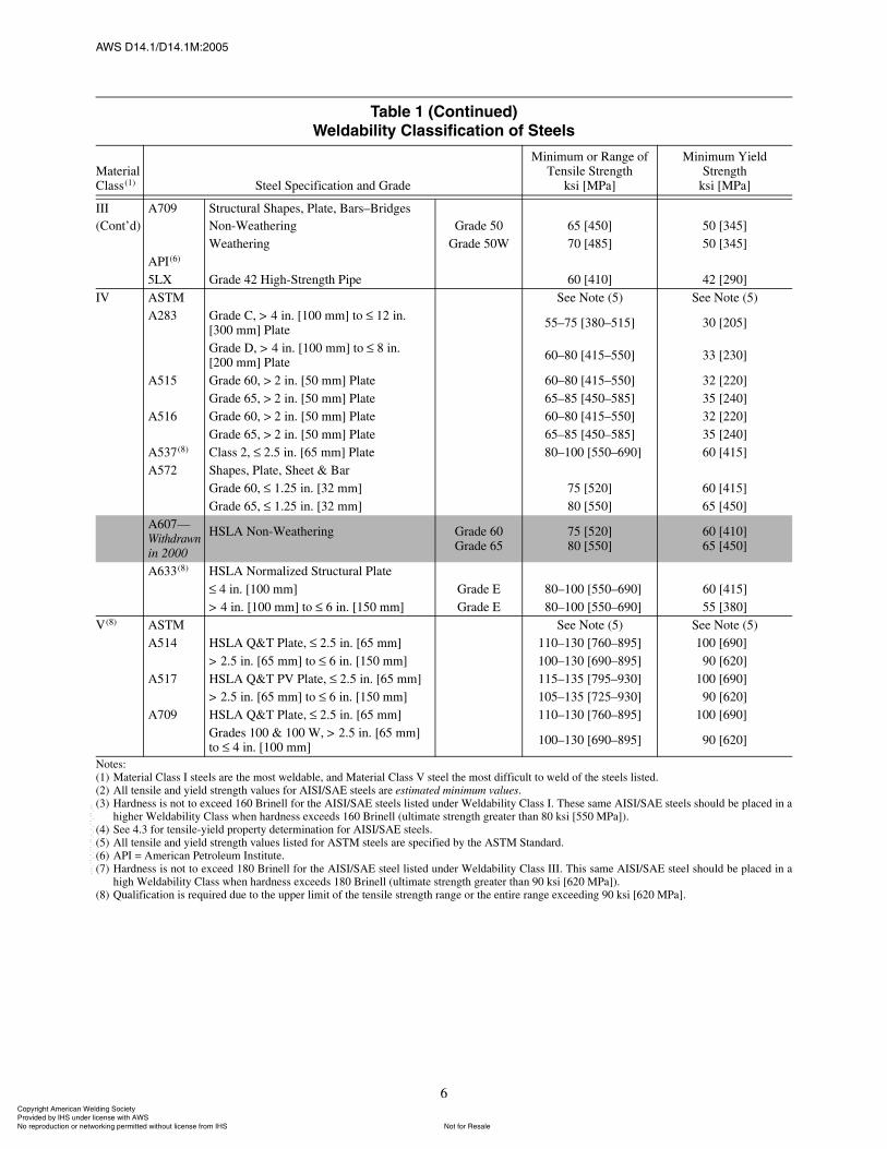
III A709 Structural Shapes, Plate, Bars�Bridges(Cont�d) Non-Weathering Grade 50 65 [450] 50 [345]
Weathering Grade 50W 70 [485] 50 [345]API(6)
5LX Grade 42 High-Strength Pipe 60 [410] 42 [290]IV ASTM See Note (5) See Note (5)
A283 Grade C, > 4 in. [100 mm] to 12 in.[300 mm] Plate 55�75 [380�515] 30 [205]
Grade D, > 4 in. [100 mm] to 8 in.[200 mm] Plate 60�80 [415�550] 33 [230]
A515 Grade 60, > 2 in. [50 mm] Plate 60�80 [415�550] 32 [220]Grade 65, > 2 in. [50 mm] Plate 65�85 [450�585] 35 [240]
A516 Grade 60, > 2 in. [50 mm] Plate 60�80 [415�550] 32 [220]Grade 65, > 2 in. [50 mm] Plate 65�85 [450�585] 35 [240]
A537(8) Class 2, 2.5 in. [65 mm] Plate 80�100 [550�690] 60 [415]A572 Shapes, Plate, Sheet & Bar
Grade 60, 1.25 in. [32 mm] 75 [520] 60 [415]Grade 65, 1.25 in. [32 mm] 80 [550] 65 [450]
A607�Withdrawnin 2000
HSLA Non-Weathering Grade 60Grade 65
75 [520]80 [550]
60 [410]65 [450]
A633(8) HSLA Normalized Structural Plate 4 in. [100 mm] Grade E 80�100 [550�690] 60 [415]
> 4 in. [100 mm] to 6 in. [150 mm] Grade E 80�100 [550�690] 55 [380]V(8) ASTM See Note (5) See Note (5)
A514 HSLA Q&T Plate, 2.5 in. [65 mm] 110�130 [760�895] 100 [690]0> 2.5 in. [65 mm] to 6 in. [150 mm] 100�130 [690�895] 90 [620]
A517 HSLA Q&T PV Plate, 2.5 in. [65 mm] 115�135 [795�930] 100 [690]0> 2.5 in. [65 mm] to 6 in. [150 mm] 105�135 [725�930] 90 [620]
A709 HSLA Q&T Plate, 2.5 in. [65 mm] 110�130 [760�895] 100 [690]0Grades 100 & 100 W, > 2.5 in. [65 mm]to 4 in. [100 mm] 100�130 [690�895] 90 [620]
Notes:(1) Material Class I steels are the most weldable, and Material Class V steel the most difficult to weld of the steels listed.(2) All tensile and yield strength values for AISI/SAE steels are estimated minimum values.(3) Hardness is not to exceed 160 Brinell for the AISI/SAE steels listed under Weldability Class I. These same AISI/SAE steels should be placed in a
higher Weldability Class when hardness exceeds 160 Brinell (ultimate strength greater than 80 ksi [550 MPa]).(4) See 4.3 for tensile-yield property determination for AISI/SAE steels.(5) All tensile and yield strength values listed for ASTM steels are specified by the ASTM Standard.(6) API = American Petroleum Institute.(7) Hardness is not to exceed 180 Brinell for the AISI/SAE steel listed under Weldability Class III. This same AISI/SAE steel should be placed in a
high Weldability Class when hardness exceeds 180 Brinell (ultimate strength greater than 90 ksi [620 MPa]).(8) Qualification is required due to the upper limit of the tensile strength range or the entire range exceeding 90 ksi [620 MPa].
Ì¿¾´» ï øݱ²¬·²«»¼÷É»´¼¿¾·´·¬§ Ý´¿·º·½¿¬·±² ±º ͬ»»´
Material Class(1) Steel Specification and Grade
Minimum or Range of Tensile Strength
ksi [MPa]
Minimum YieldStrength
ksi [MPa]
ݱ°§®·¹¸¬ ß³»®·½¿² É»´¼·²¹ ͱ½·»¬§ Ю±ª·¼»¼ ¾§ ×ØÍ «²¼»® ´·½»²» ©·¬¸ ßÉÍ
Ò±¬ º±® λ¿´»Ò± ®»°®±¼«½¬·±² ±® ²»¬©±®µ·²¹ °»®³·¬¬»¼ ©·¬¸±«¬ ´·½»²» º®±³ ×ØÍ
óóÀôôÀôôÀóÀóÀôôÀôôÀôÀôôÀóóó
ßÉÍ ÜïìòïñÜïìòïÓæîððë
7
5. Allowable Stresses5.1 General. The allowable stresses for base metal andweld metal and the type of fatigue analysis to be usedshall conform to the requirements of the design specifi-cations from organizations such as the American Insti-tute of Steel Construction (AISC), the American Societyof Mechanical Engineers (ASME), the Crane Manufac-turers Association of America (CMAA), or the MonorailManufacturers Association (MMA). In the absence ofother requirements, the allowable stresses in the basemetal and the weld metal shall conform to the followingrequirements.
5.1.1 Base Metal. Unless otherwise specified by thedesign specifications in 5.1, the allowable tensile or com-pressive stress in the base metal shall be 50% of the yieldstrength, and the allowable shear stress in the base metalshall be 40% of the yield strength for members not con-trolled by buckling.
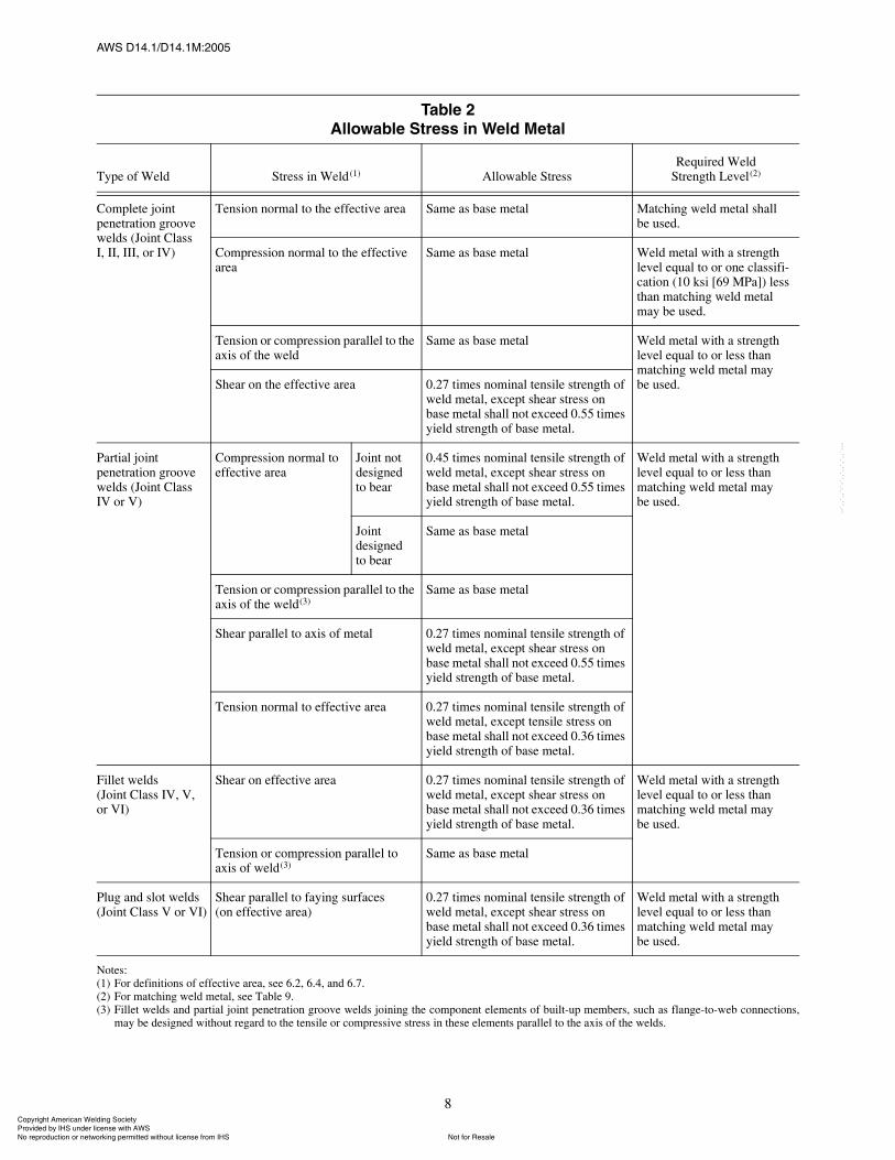
5.1.2 Weld Metal. Allowable stresses in the weldmetal shall conform to Table 2.
5.2 Fatigue. The maximum stress in welded joints sub-ject to repeated stress fluctuations or reversals shall notexceed:
(1) The allowable tensile or compressive stress in5.1; or
(2) The allowable fatigue stress as defined in thedesign specifications indicated in 5.1.
In the absence of other requirements, fatigue loadingshall be addressed as follows:
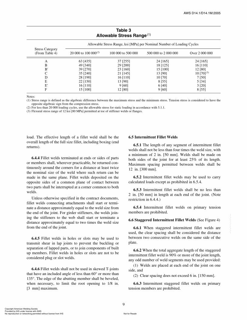
5.2.1 Members subject to repeated loading shall bedesigned so that the maximum stress does not exceedthat allowed by 5.1 and the stress range does not exceedthe value given in Table 3 for the applicable stress cate-gory and nominal number of loading cycles. Stress cate-gories for weld joint configurations are described inTable 4 and illustrated in Figure 1.
5.2.2 The stress range is the maximum stress minusthe minimum stress. The minimum stress is considerednegative if it is opposite in direction to the maximumstress. The nominal number of loading cycles shall be thenumber defined in the design specification for the dutycycle class or determined by the Engineer for the dutycycle and life specified in the purchase contract.
6. Weld Joint Design6.1 General Requirements. Complete informationregarding location, type, size, and extent of all welds andwelded joints shall be shown on the drawings. Any spe-cial inspection requirements shall be noted on the draw-
ings or other appropriate documents. In general, designdetails should minimize restraint, avoid undue concen-tration of welding, and afford ample access for deposit-ing the weld metal.
6.2 Groove Welds
6.2.1 The effective area of a weld shall be the effec-tive weld length multiplied by the effective throat.
6.2.2 The effective length of any groove weld is thelength throughout which the correctly proportioned weldcross section exists.
6.2.3 The effective throat is the minimum distancefrom the root of a weld to its face, less any reinforce-ment. For a complete joint penetration weld, this shall bethe nominal thickness of the thinner part joined.
6.2.4 The effective throat of a partial penetration weldis joint penetration below the surface of the member (seeTable 5 for the minimum effective throat required).
Shop or working drawings shall specify the groovedepths (S) applicable for the weld size (E) required forthe welding process and position of welding to be used.
6.2.5 Groove welds made from one side only, exceptin secondary members, are prohibited unless they arecompletely fused to a backing strip, or qualified in accor-dance with the requirements of this specification (see6.9).
6.2.6 A complete joint penetration groove weld is onethat has been welded from both sides, or from one side,in which the weld metal completely fills the groove andis fused to the base metal throughout its total thickness(see 6.9).
6.3 Intermittent Groove Welds. Intermittent groovewelds are prohibited, except in secondary members.
6.4 Fillet Welds (See Figures 2 and 3)
6.4.1 The minimum fillet weld size shall be as shownin Table 6, except where fillet welds are used to reinforcegroove welds (see Figure 3).
6.4.2 The maximum fillet weld size permitted alongthe edges of members shall be:
(1) The thickness of the base metal when the metal isless than 1/4 in. [6 mm] thick; or
(2) The thickness of the base metal less 1/16 in.[2 mm] when the metal is 1/4 in. [6 mm] or more inthickness, unless the weld is designated on the drawingto be built out to obtain full throat thickness.
6.4.3 The effective weld area shall be the effectiveweld length multiplied by the effective throat. The shearstress in a fillet weld shall be considered as applied tothis effective area regardless of the direction of applied
ݱ°§®·¹¸¬ ß³»®·½¿² É»´¼·²¹ ͱ½·»¬§ Ю±ª·¼»¼ ¾§ ×ØÍ «²¼»® ´·½»²» ©·¬¸ ßÉÍ
Ò±¬ º±® λ¿´»Ò± ®»°®±¼«½¬·±² ±® ²»¬©±®µ·²¹ °»®³·¬¬»¼ ©·¬¸±«¬ ´·½»²» º®±³ ×ØÍ
óóÀôôÀôôÀóÀóÀôôÀôôÀôÀôôÀóóó
ßÉÍ ÜïìòïñÜïìòïÓæîððë
8
Ì¿¾´» îß´´±©¿¾´» ͬ®» ·² É»´¼ Ó»¬¿´
Type of Weld Stress in Weld (1) Allowable StressRequired Weld
Strength Level(2)
Complete jointpenetration groove welds (Joint ClassI, II, III, or IV)
Tension normal to the effective area Same as base metal Matching weld metal shall be used.
Compression normal to the effective area
Same as base metal Weld metal with a strength level equal to or one classifi-cation (10 ksi [69 MPa]) less than matching weld metal may be used.
Tension or compression parallel to the axis of the weld
Same as base metal Weld metal with a strength level equal to or less than matching weld metal may be used.Shear on the effective area 0.27 times nominal tensile strength of
weld metal, except shear stress on base metal shall not exceed 0.55 times yield strength of base metal.
Partial joint penetration groove welds (Joint ClassIV or V)
Compression normal to effective area
Joint not designedto bear
0.45 times nominal tensile strength of weld metal, except shear stress on base metal shall not exceed 0.55 times yield strength of base metal.
Weld metal with a strength level equal to or less than matching weld metal may be used.
Joint designedto bear
Same as base metal
Tension or compression parallel to the axis of the weld(3)
Same as base metal
Shear parallel to axis of metal 0.27 times nominal tensile strength of weld metal, except shear stress on base metal shall not exceed 0.55 times yield strength of base metal.
Tension normal to effective area 0.27 times nominal tensile strength of weld metal, except tensile stress on base metal shall not exceed 0.36 times yield strength of base metal.
Fillet welds(Joint Class IV, V,or VI)
Shear on effective area 0.27 times nominal tensile strength of weld metal, except shear stress on base metal shall not exceed 0.36 times yield strength of base metal.
Weld metal with a strength level equal to or less than matching weld metal may be used.
Tension or compression parallel to axis of weld(3)
Same as base metal
Plug and slot welds(Joint Class V or VI)
Shear parallel to faying surfaces (on effective area)
0.27 times nominal tensile strength of weld metal, except shear stress on base metal shall not exceed 0.36 times yield strength of base metal.
Weld metal with a strength level equal to or less than matching weld metal may be used.
Notes:(1) For definitions of effective area, see 6.2, 6.4, and 6.7.(2) For matching weld metal, see Table 9.(3) Fillet welds and partial joint penetration groove welds joining the component elements of built-up members, such as flange-to-web connections,
may be designed without regard to the tensile or compressive stress in these elements parallel to the axis of the welds.
ݱ°§®·¹¸¬ ß³»®·½¿² É»´¼·²¹ ͱ½·»¬§ Ю±ª·¼»¼ ¾§ ×ØÍ «²¼»® ´·½»²» ©·¬¸ ßÉÍ
Ò±¬ º±® λ¿´»Ò± ®»°®±¼«½¬·±² ±® ²»¬©±®µ·²¹ °»®³·¬¬»¼ ©·¬¸±«¬ ´·½»²» º®±³ ×ØÍ
óóÀôôÀôôÀóÀóÀôôÀôôÀôÀôôÀóóó
ßÉÍ ÜïìòïñÜïìòïÓæîððë
9
load. The effective length of a fillet weld shall be theoverall length of the full size fillet, including boxing (endreturns).
6.4.4 Fillet welds terminated at ends or sides of partsor members shall, wherever practicable, be returned con-tinuously around the corners for a distance at least twicethe nominal size of the weld where such return can bemade in the same plane. Fillet welds deposited on theopposite sides of a common plane of contact betweentwo parts shall be interrupted at a corner common to bothwelds.
Unless otherwise specified in the contract documents,fillet welds connecting attachments shall start or termi-nate a distance approximately equal to the weld size fromthe end of the joint. For girder stiffeners, the welds join-ing the stiffeners to the web shall start or terminate adistance approximately equal to two times the weld sizefrom the end of the joint.
6.4.5 Fillet welds in holes or slots may be used totransmit shear in lap joints to prevent the buckling orseparation of lapped parts, or to join components of builtup members. Fillet welds in holes or slots are not to beconsidered plug or slot welds.
6.4.6 Fillet welds shall not be used in skewed T-jointsthat have an included angle of less than 60° or more than135°. The edge of the abutting member shall be beveled,when necessary, to limit the root opening to 1/8 in.[3 mm] maximum.
6.5 Intermittent Fillet Welds
6.5.1 The length of any segment of intermittent filletwelds shall not be less than four times the weld size, witha minimum of 2 in. [50 mm]. Welds shall be made onboth sides of the joint for at least 25% of its length.Maximum spacing permitted between welds shall be12 in. [300 mm].
6.5.2 Intermittent fillet welds may be used to carrycalculated loads except as prohibited in 6.5.4.
6.5.3 Intermittent fillet welds shall be no less than2 in. [50 mm] in length at each end of the joint. (Noterestriction in 6.4.4.)
6.5.4 Intermittent fillet welds on primary tensionmembers are prohibited.
6.6 Staggered Intermittent Fillet Welds (See Figure 4)
6.6.1 When staggered intermittent fillet welds areused, the clear spacing shall be considered the distancebetween two consecutive welds on the same side of theplate.
6.6.2 When the total aggregate length of the staggeredintermittent fillet weld is 90% or more of the joint length,any odd number of weld segments may be used provided:
(1) Welds are placed at each end of the joint on oneside, and
(2) Clear spacing does not exceed 6 in. [150 mm].
6.6.3 Intermittent staggered fillet welds on primarytension members are prohibited.
Ì¿¾´» íß´´±©¿¾´» ͬ®» ο²¹» øï÷
Stress Category (From Table 4)
Allowable Stress Range, ksi [MPa] per Nominal Number of Loading Cycles
20 000 to 100 000(2) 100 000 to 500 000 500 000 to 2 000 000 Over 2 000 000
ABB'CDEE'F
63 [435]49 [340]39 [270]35 [240]28 [190]22 [150]16 [110]15 [100]
37 [255]29 [200]23 [160]21 [145]16 [110]13 [90]9 [60]
12 [80]
24 [165]18 [125]15 [100]13 [90]10 [70]8 [55]6 [40]9 [60]
24 [165]16 [110]12 [80]10 [70](3)
7 [50]5 [34]3 [20]8 [55]
Notes:(1) Stress range is defined as the algebraic difference between the maximum stress and the minimum stress. Tension stress is considered to have the
opposite algebraic sign from the compression stress.(2) For less than 20 000 loading cycles, use the allowable stress for static loading in accordance with 5.1.1.(3) Flexural stress range of 12 ksi [80 MPa] permitted at toe of stiffener welds or flanges.
ݱ°§®·¹¸¬ ß³»®·½¿² É»´¼·²¹ ͱ½·»¬§ Ю±ª·¼»¼ ¾§ ×ØÍ «²¼»® ´·½»²» ©·¬¸ ßÉÍ
Ò±¬ º±® λ¿´»Ò± ®»°®±¼«½¬·±² ±® ²»¬©±®µ·²¹ °»®³·¬¬»¼ ©·¬¸±«¬ ´·½»²» º®±³ ×ØÍ
óóÀôôÀôôÀóÀóÀôôÀôôÀôÀôôÀóóó
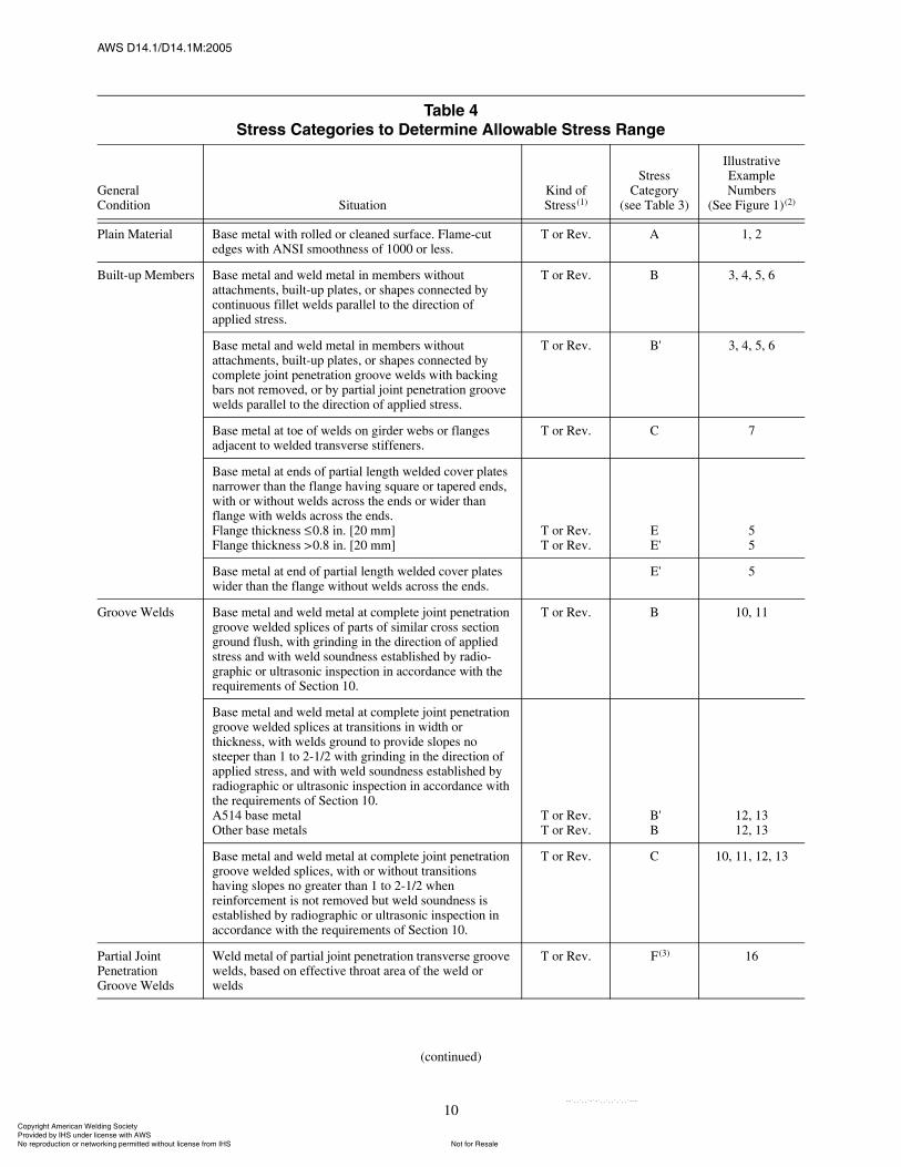
ßÉÍ ÜïìòïñÜïìòïÓæîððë
10
Ì¿¾´» ìͬ®» Ý¿¬»¹±®·» ¬± Ü»¬»®³·²» ß´´±©¿¾´» ͬ®» ο²¹»
General Condition Situation
Kind ofStress(1)
StressCategory
(see Table 3)
Illustrative Example Numbers
(See Figure 1)(2)
Plain Material Base metal with rolled or cleaned surface. Flame-cut edges with ANSI smoothness of 1000 or less.
T or Rev. A 1, 2
Built-up Members Base metal and weld metal in members without attachments, built-up plates, or shapes connected by continuous fillet welds parallel to the direction of applied stress.
T or Rev. B 3, 4, 5, 6
Base metal and weld metal in members without attachments, built-up plates, or shapes connected bycomplete joint penetration groove welds with backing bars not removed, or by partial joint penetration groove welds parallel to the direction of applied stress.
T or Rev. 'B' 3, 4, 5, 6
Base metal at toe of welds on girder webs or flanges adjacent to welded transverse stiffeners.
T or Rev. C 7
Base metal at ends of partial length welded cover plates narrower than the flange having square or tapered ends, with or without welds across the ends or wider than flange with welds across the ends.Flange thickness 0.8 in. [20 mm]Flange thickness >0.8 in. [20 mm]
T or Rev.T or Rev.
E'E'
55
Base metal at end of partial length welded cover plates wider than the flange without welds across the ends.
'E' 5
Groove Welds Base metal and weld metal at complete joint penetration groove welded splices of parts of similar cross section ground flush, with grinding in the direction of applied stress and with weld soundness established by radio-graphic or ultrasonic inspection in accordance with the requirements of Section 10.
T or Rev. B 10, 11
Base metal and weld metal at complete joint penetration groove welded splices at transitions in width or thickness, with welds ground to provide slopes no steeper than 1 to 2-1/2 with grinding in the direction of applied stress, and with weld soundness established by radiographic or ultrasonic inspection in accordance with the requirements of Section 10.A514 base metalOther base metals
T or Rev.T or Rev.
'B'B
12, 1312, 13
Base metal and weld metal at complete joint penetration groove welded splices, with or without transitions having slopes no greater than 1 to 2-1/2 when reinforcement is not removed but weld soundness is established by radiographic or ultrasonic inspection in accordance with the requirements of Section 10.
T or Rev. C 10, 11, 12, 13
Partial Joint Penetration Groove Welds
Weld metal of partial joint penetration transverse groove welds, based on effective throat area of the weld or welds
T or Rev. (3)F(3) 16
(continued)
ݱ°§®·¹¸¬ ß³»®·½¿² É»´¼·²¹ ͱ½·»¬§ Ю±ª·¼»¼ ¾§ ×ØÍ «²¼»® ´·½»²» ©·¬¸ ßÉÍ
Ò±¬ º±® λ¿´»Ò± ®»°®±¼«½¬·±² ±® ²»¬©±®µ·²¹ °»®³·¬¬»¼ ©·¬¸±«¬ ´·½»²» º®±³ ×ØÍ
óóÀôôÀôôÀóÀóÀôôÀôôÀôÀôôÀóóó
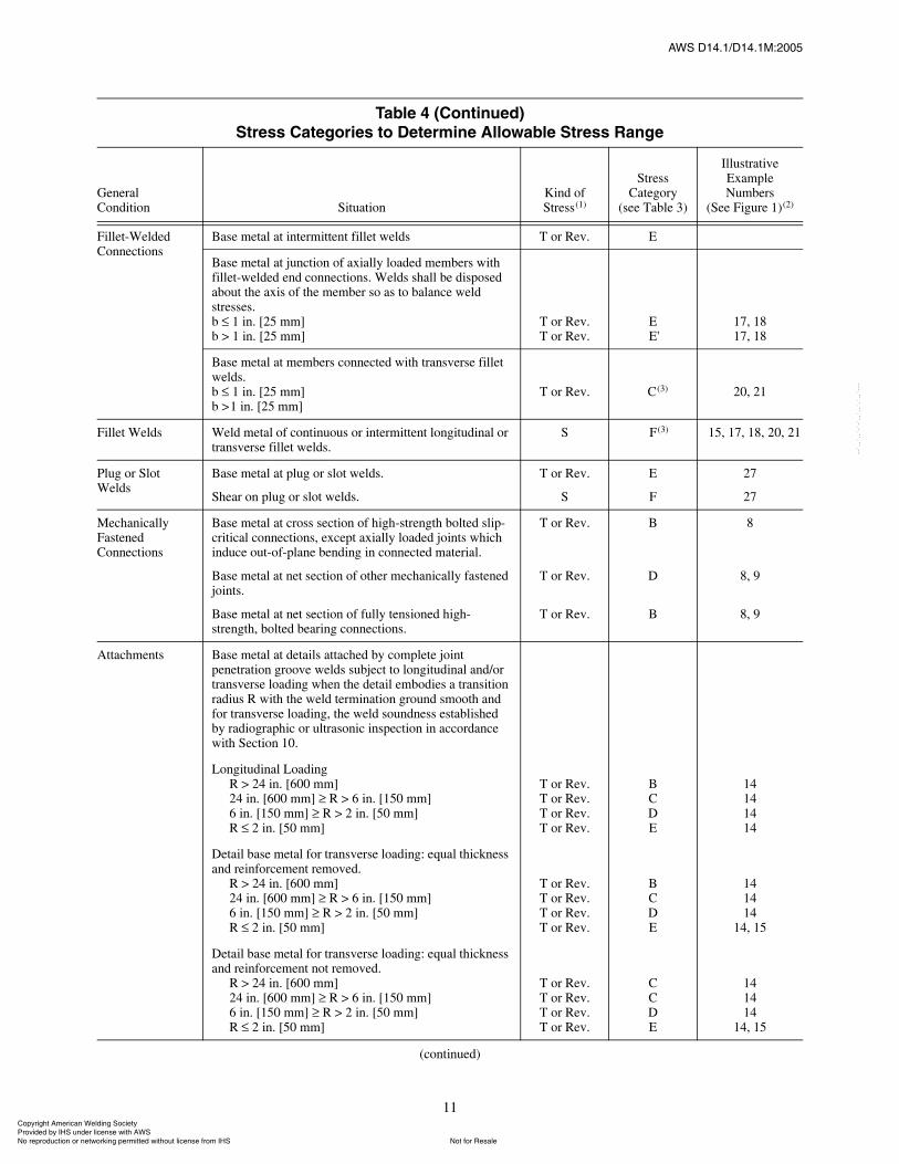
ßÉÍ ÜïìòïñÜïìòïÓæîððë
11
Fillet-Welded Connections
Base metal at intermittent fillet welds T or Rev. E
Base metal at junction of axially loaded members with fillet-welded end connections. Welds shall be disposed about the axis of the member so as to balance weld stresses.b 1 in. [25 mm]b > 1 in. [25 mm]
T or Rev.T or Rev.
E'E'
17, 1817, 18
Base metal at members connected with transverse fillet welds.b 1 in. [25 mm]b >1 in. [25 mm]
T or Rev. 3cC(3) 20, 21
Fillet Welds Weld metal of continuous or intermittent longitudinal or transverse fillet welds.
S (3)F(3) 15, 17, 18, 20, 21
Plug or Slot Welds
Base metal at plug or slot welds.
Shear on plug or slot welds.
T or Rev.
S
E
F
27
27
Mechanically Fastened Connections
Base metal at cross section of high-strength bolted slip-critical connections, except axially loaded joints which induce out-of-plane bending in connected material.
Base metal at net section of other mechanically fastened joints.
Base metal at net section of fully tensioned high-strength, bolted bearing connections.
T or Rev.
T or Rev.
T or Rev.
B
D
B
8
8, 9
8, 9
Attachments Base metal at details attached by complete joint penetration groove welds subject to longitudinal and/or transverse loading when the detail embodies a transition radius R with the weld termination ground smooth and for transverse loading, the weld soundness established by radiographic or ultrasonic inspection in accordance with Section 10.
Longitudinal LoadingR > 24 in. [600 mm]24 in. [600 mm] R > 6 in. [150 mm]6 in. [150 mm] R > 2 in. [50 mm]R 2 in. [50 mm]
T or Rev.T or Rev.T or Rev.T or Rev.
BCDE
14141414
Detail base metal for transverse loading: equal thickness and reinforcement removed.
R > 24 in. [600 mm]24 in. [600 mm] R > 6 in. [150 mm]6 in. [150 mm] R > 2 in. [50 mm]R 2 in. [50 mm]
T or Rev.T or Rev.T or Rev.T or Rev.
BCDE
141414
14, 15
Detail base metal for transverse loading: equal thickness and reinforcement not removed.
R > 24 in. [600 mm]24 in. [600 mm] R > 6 in. [150 mm]6 in. [150 mm] R > 2 in. [50 mm]R 2 in. [50 mm]
T or Rev.T or Rev.T or Rev.T or Rev.
CCDE
141414
14, 15
Ì¿¾´» ì øݱ²¬·²«»¼÷ͬ®» Ý¿¬»¹±®·» ¬± Ü»¬»®³·²» ß´´±©¿¾´» ͬ®» ο²¹»
General Condition Situation
Kind ofStress(1)
StressCategory
(see Table 3)
Illustrative Example Numbers
(See Figure 1)(2)
(continued)
ݱ°§®·¹¸¬ ß³»®·½¿² É»´¼·²¹ ͱ½·»¬§ Ю±ª·¼»¼ ¾§ ×ØÍ «²¼»® ´·½»²» ©·¬¸ ßÉÍ
Ò±¬ º±® λ¿´»Ò± ®»°®±¼«½¬·±² ±® ²»¬©±®µ·²¹ °»®³·¬¬»¼ ©·¬¸±«¬ ´·½»²» º®±³ ×ØÍ
óóÀôôÀôôÀóÀóÀôôÀôôÀôÀôôÀóóó
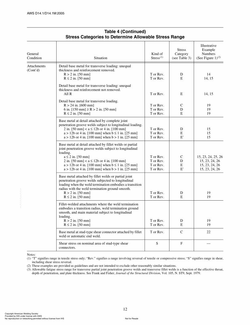
ßÉÍ ÜïìòïñÜïìòïÓæîððë
12
Attachments (Cont�d)
Detail base metal for transverse loading: unequal thickness and reinforcement removed.
R > 2 in. [50 mm]R 2 in. [50 mm]
T or Rev.T or Rev.
DE
1414, 15
Detail base metal for transverse loading: unequal thickness and reinforcement not removed.
All R T or Rev. E 14, 15
Detail base metal for transverse loading.R > 24 in. [600 mm]6 in. [150 mm] R > 2 in. [50 mm]R 2 in. [50 mm]
T or Rev.T or Rev.T or Rev.
CDE
191919
Base metal at detail attached by complete joint penetration groove welds subject to longitudinal loading.
2 in. [50 mm] < a 12b or 4 in. [100 mm]a > 12b or 4 in. [100 mm] when b 1 in. [25 mm]a > 12b or 4 in. [100 mm] when b > 1 in. [25 mm]
T or Rev.T or Rev.T or Rev.
DE'E'
151515
Base metal at detail attached by fillet welds or partial joint penetration groove welds subject to longitudinal loading.
a 2 in. [50 mm]2 in. [50 mm] < a 12b or 4 in. [100 mm]a > 12b or 4 in. [100 mm] when b 1 in. [25 mm]a > 12b or 4 in. [100 mm] when b > 1 in. [25 mm]
T or Rev.T or Rev.T or Rev.T or Rev.
CDE'E'
15, 23, 24, 25, 2615, 23, 24, 2615, 23, 24, 2615, 23, 24, 26
Base metal attached by fillet welds or partial joint penetration groove welds subjected to longitudinal loading when the weld termination embodies a transition radius with the weld termination ground smooth.
R > 2 in. [50 mm]R 2 in. [50 mm]
T or Rev.T or Rev.
DE
1919
Fillet-welded attachments where the weld termination embodies a transition radius, weld termination ground smooth, and main material subject to longitudinal loading.
R > 2 in. [50 mm]R 2 in. [50 mm]
T or Rev.T or Rev.
DE
1919
Base metal at stud-type shear connector attached by fillet weld or automatic end weld.
T or Rev. C 22
Shear stress on nominal area of stud-type shear connectors.
S F �
Notes:(1) �T� signifies range in tensile stress only; �Rev.� signifies a range involving reversal of tensile or compressive stress; �S� signifies range in shear,
including shear stress reversal.(2) These examples are provided as guidelines and are not intended to exclude other reasonably similar situations.(3) Allowable fatigue stress range for transverse partial joint penetration groove welds and transverse fillet welds is a function of the effective throat,
depth of penetration, and plate thickness. See Frank and Fisher, Journal of the Structural Division, Vol. 105, N. ST9, Sept. 1979.
Ì¿¾´» ì øݱ²¬·²«»¼÷ͬ®» Ý¿¬»¹±®·» ¬± Ü»¬»®³·²» ß´´±©¿¾´» ͬ®» ο²¹»
General Condition Situation
Kind ofStress(1)
StressCategory
(see Table 3)
Illustrative Example Numbers
(See Figure 1)(2)
ݱ°§®·¹¸¬ ß³»®·½¿² É»´¼·²¹ ͱ½·»¬§ Ю±ª·¼»¼ ¾§ ×ØÍ «²¼»® ´·½»²» ©·¬¸ ßÉÍ
Ò±¬ º±® λ¿´»Ò± ®»°®±¼«½¬·±² ±® ²»¬©±®µ·²¹ °»®³·¬¬»¼ ©·¬¸±«¬ ´·½»²» º®±³ ×ØÍ
óóÀôôÀôôÀóÀóÀôôÀôôÀôÀôôÀóóó
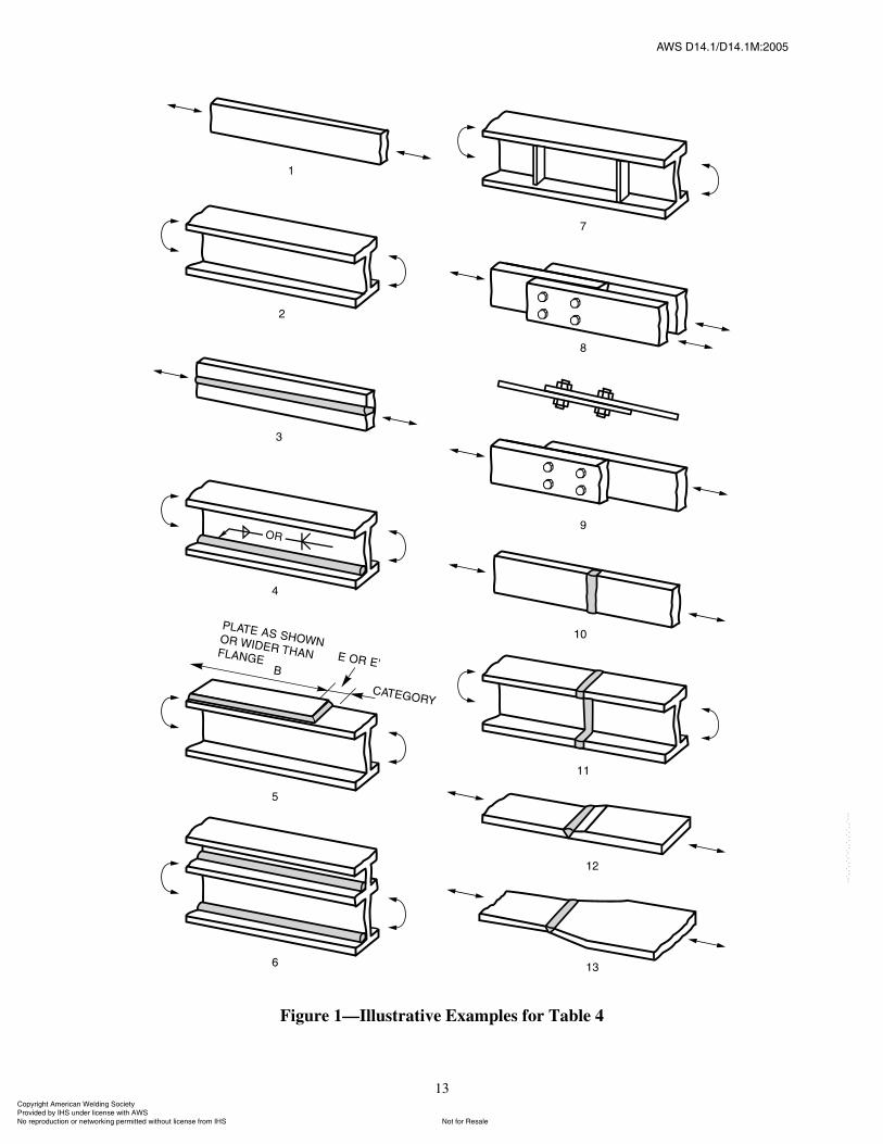
ßÉÍ ÜïìòïñÜïìòïÓæîððë
13
Figure 1�Illustrative Examples for Table 4
ݱ°§®·¹¸¬ ß³»®·½¿² É»´¼·²¹ ͱ½·»¬§ Ю±ª·¼»¼ ¾§ ×ØÍ «²¼»® ´·½»²» ©·¬¸ ßÉÍ
Ò±¬ º±® λ¿´»Ò± ®»°®±¼«½¬·±² ±® ²»¬©±®µ·²¹ °»®³·¬¬»¼ ©·¬¸±«¬ ´·½»²» º®±³ ×ØÍ
óóÀôôÀôôÀóÀóÀôôÀôôÀôÀôôÀóóó
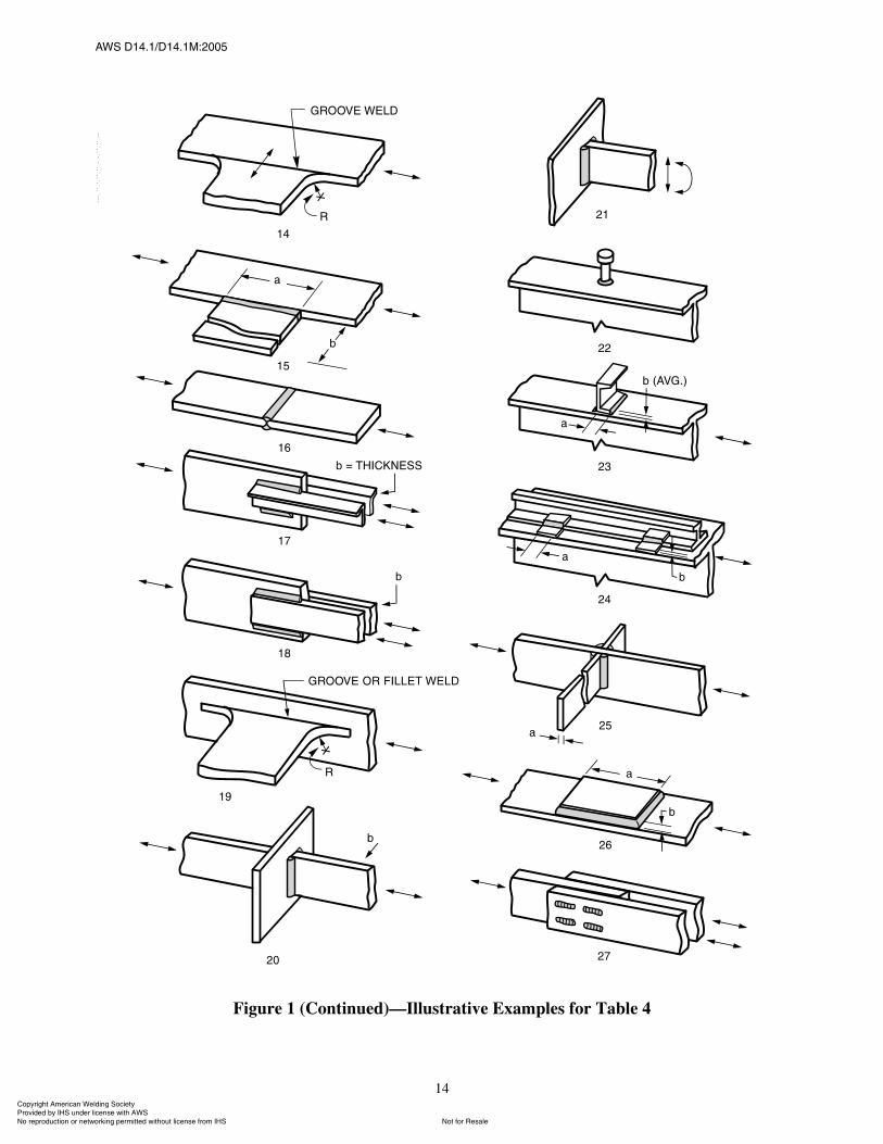
ßÉÍ ÜïìòïñÜïìòïÓæîððë
14
Figure 1 (Continued)�Illustrative Examples for Table 4
ݱ°§®·¹¸¬ ß³»®·½¿² É»´¼·²¹ ͱ½·»¬§ Ю±ª·¼»¼ ¾§ ×ØÍ «²¼»® ´·½»²» ©·¬¸ ßÉÍ
Ò±¬ º±® λ¿´»Ò± ®»°®±¼«½¬·±² ±® ²»¬©±®µ·²¹ °»®³·¬¬»¼ ©·¬¸±«¬ ´·½»²» º®±³ ×ØÍ
óóÀôôÀôôÀóÀóÀôôÀôôÀôÀôôÀóóó
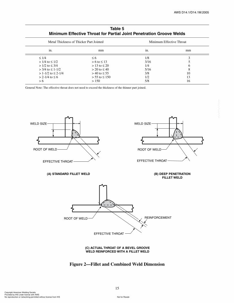
ßÉÍ ÜïìòïñÜïìòïÓæîððë
15
Figure 2�Fillet and Combined Weld Dimension
Ì¿¾´» ëÓ·²·³«³ Ûºº»½¬·ª» ̸®±¿¬ º±® ﮬ·¿´ Ö±·²¬ л²»¬®¿¬·±² Ù®±±ª» É»´¼
Metal Thickness of Thicker Part Jointed Minimum Effective Throat
in. mm in. mm
1/4> 1/4 to 1/2> 1/2 to 3/4> 3/4 to 1-1/2> 1-1/2 to 2-1/4> 2-1/4 to 6> 6
6> 6 to 13> 13 to 20> 20 to 40> 40 to 55> 55 to 150> 150
1/83/161/45/163/81/25/8
3568
101316
General Note: The effective throat does not need to exceed the thickness of the thinner part joined.
ݱ°§®·¹¸¬ ß³»®·½¿² É»´¼·²¹ ͱ½·»¬§ Ю±ª·¼»¼ ¾§ ×ØÍ «²¼»® ´·½»²» ©·¬¸ ßÉÍ
Ò±¬ º±® λ¿´»Ò± ®»°®±¼«½¬·±² ±® ²»¬©±®µ·²¹ °»®³·¬¬»¼ ©·¬¸±«¬ ´·½»²» º®±³ ×ØÍ
óóÀôôÀôôÀóÀóÀôôÀôôÀôÀôôÀóóó
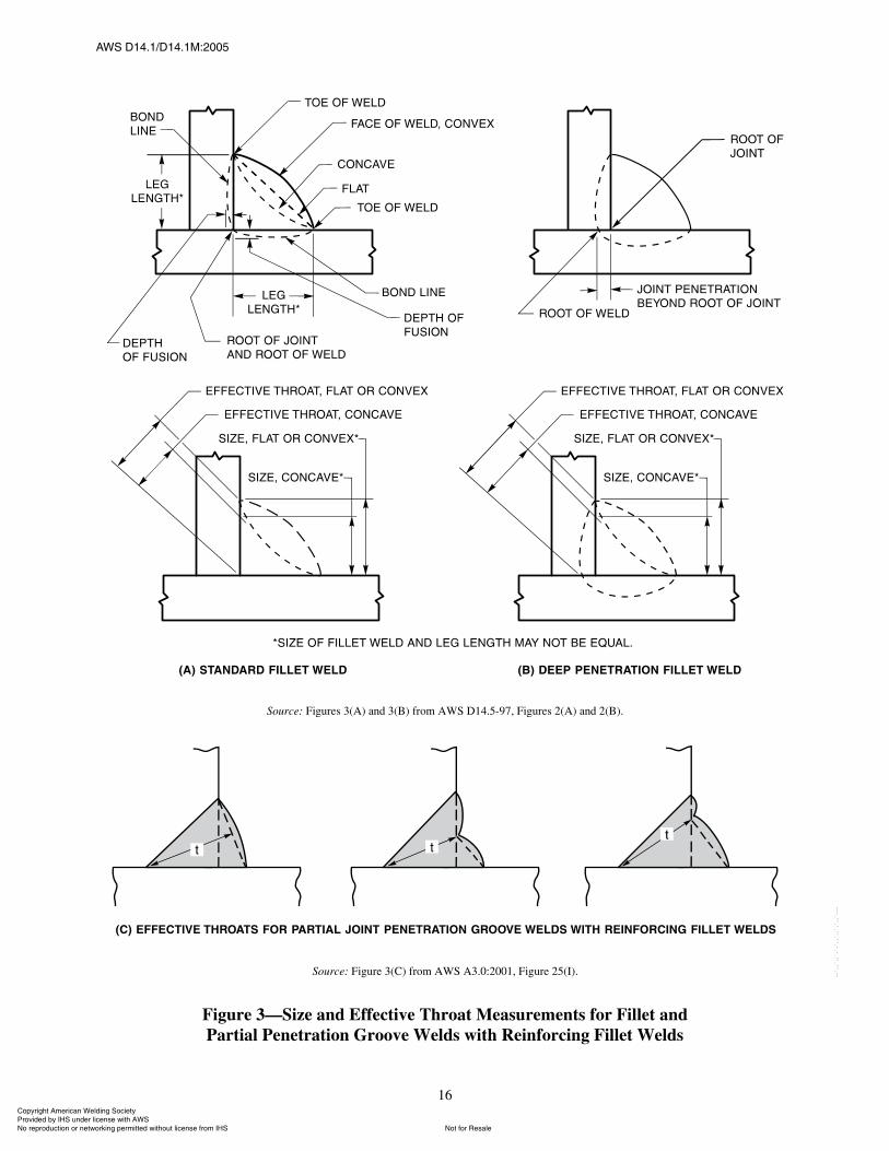
ßÉÍ ÜïìòïñÜïìòïÓæîððë
16
Source: Figures 3(A) and 3(B) from AWS D14.5-97, Figures 2(A) and 2(B).
Source: Figure 3(C) from AWS A3.0:2001, Figure 25(I).
Figure 3�Size and Effective Throat Measurements for Fillet andPartial Penetration Groove Welds with Reinforcing Fillet Welds
ݱ°§®·¹¸¬ ß³»®·½¿² É»´¼·²¹ ͱ½·»¬§ Ю±ª·¼»¼ ¾§ ×ØÍ «²¼»® ´·½»²» ©·¬¸ ßÉÍ
Ò±¬ º±® λ¿´»Ò± ®»°®±¼«½¬·±² ±® ²»¬©±®µ·²¹ °»®³·¬¬»¼ ©·¬¸±«¬ ´·½»²» º®±³ ×ØÍ
óóÀôôÀôôÀóÀóÀôôÀôôÀôÀôôÀóóó
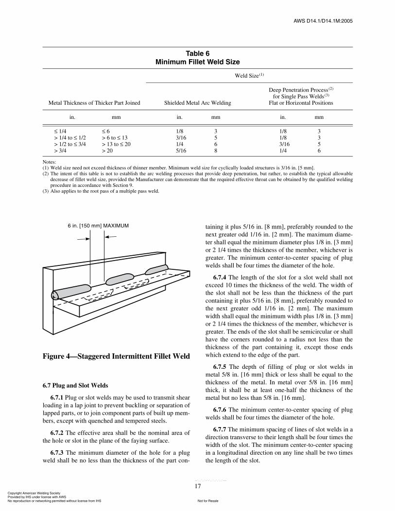
ßÉÍ ÜïìòïñÜïìòïÓæîððë
17
6.7 Plug and Slot Welds
6.7.1 Plug or slot welds may be used to transmit shearloading in a lap joint to prevent buckling or separation oflapped parts, or to join component parts of built up mem-bers, except with quenched and tempered steels.
6.7.2 The effective area shall be the nominal area ofthe hole or slot in the plane of the faying surface.
6.7.3 The minimum diameter of the hole for a plugweld shall be no less than the thickness of the part con-
taining it plus 5/16 in. [8 mm], preferably rounded to thenext greater odd 1/16 in. [2 mm]. The maximum diame-ter shall equal the minimum diameter plus 1/8 in. [3 mm]or 2 1/4 times the thickness of the member, whichever isgreater. The minimum center-to-center spacing of plugwelds shall be four times the diameter of the hole.
6.7.4 The length of the slot for a slot weld shall notexceed 10 times the thickness of the weld. The width ofthe slot shall not be less than the thickness of the partcontaining it plus 5/16 in. [8 mm], preferably rounded tothe next greater odd 1/16 in. [2 mm]. The maximumwidth shall equal the minimum width plus 1/8 in. [3 mm]or 2 1/4 times the thickness of the member, whichever isgreater. The ends of the slot shall be semicircular or shallhave the corners rounded to a radius not less than thethickness of the part containing it, except those endswhich extend to the edge of the part.
6.7.5 The depth of filling of plug or slot welds inmetal 5/8 in. [16 mm] thick or less shall be equal to thethickness of the metal. In metal over 5/8 in. [16 mm]thick, it shall be at least one-half the thickness of themetal but no less than 5/8 in. [16 mm].
6.7.6 The minimum center-to-center spacing of plugwelds shall be four times the diameter of the hole.
6.7.7 The minimum spacing of lines of slot welds in adirection transverse to their length shall be four times thewidth of the slot. The minimum center-to-center spacingin a longitudinal direction on any line shall be two timesthe length of the slot.
Ì¿¾´» êÓ·²·³«³ Ú·´´»¬ É»´¼ Í·¦»
Metal Thickness of Thicker Part Joined
Weld Size(1)
Shielded Metal Arc Welding
Deep Penetration Process(2)
for Single Pass Welds(3)
Flat or Horizontal Positions
in. mm in. mm in. mm
1/4> 1/4 to 1/2> 1/2 to 3/4> 3/4
6> 6 to 13> 13 to 20> 20
1/83/161/45/16
3568
1/81/83/161/4
3356
Notes:(1) Weld size need not exceed thickness of thinner member. Minimum weld size for cyclically loaded structures is 3/16 in. [5 mm].(2) The intent of this table is not to establish the arc welding processes that provide deep penetration, but rather, to establish the typical allowable
decrease of fillet weld size, provided the Manufacturer can demonstrate that the required effective throat can be obtained by the qualified weldingprocedure in accordance with Section 9.
(3) Also applies to the root pass of a multiple pass weld.
Figure 4�Staggered Intermittent Fillet Weld
ݱ°§®·¹¸¬ ß³»®·½¿² É»´¼·²¹ ͱ½·»¬§ Ю±ª·¼»¼ ¾§ ×ØÍ «²¼»® ´·½»²» ©·¬¸ ßÉÍ
Ò±¬ º±® λ¿´»Ò± ®»°®±¼«½¬·±² ±® ²»¬©±®µ·²¹ °»®³·¬¬»¼ ©·¬¸±«¬ ´·½»²» º®±³ ×ØÍ
óóÀôôÀôôÀóÀóÀôôÀôôÀôÀôôÀóóó
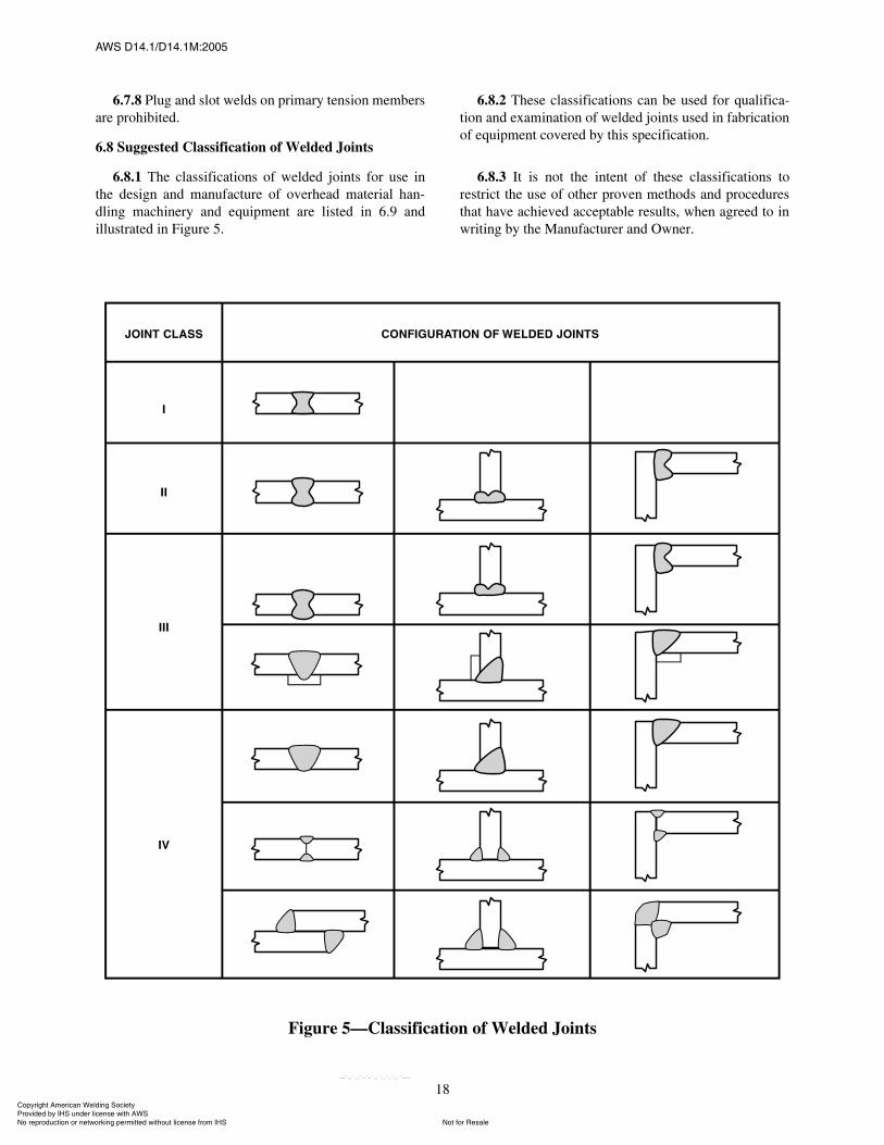
ßÉÍ ÜïìòïñÜïìòïÓæîððë
18
6.7.8 Plug and slot welds on primary tension membersare prohibited.
6.8 Suggested Classification of Welded Joints
6.8.1 The classifications of welded joints for use inthe design and manufacture of overhead material han-dling machinery and equipment are listed in 6.9 andillustrated in Figure 5.
6.8.2 These classifications can be used for qualifica-tion and examination of welded joints used in fabricationof equipment covered by this specification.
6.8.3 It is not the intent of these classifications torestrict the use of other proven methods and proceduresthat have achieved acceptable results, when agreed to inwriting by the Manufacturer and Owner.
Figure 5�Classification of Welded Joints
ݱ°§®·¹¸¬ ß³»®·½¿² É»´¼·²¹ ͱ½·»¬§ Ю±ª·¼»¼ ¾§ ×ØÍ «²¼»® ´·½»²» ©·¬¸ ßÉÍ
Ò±¬ º±® λ¿´»Ò± ®»°®±¼«½¬·±² ±® ²»¬©±®µ·²¹ °»®³·¬¬»¼ ©·¬¸±«¬ ´·½»²» º®±³ ×ØÍ
óóÀôôÀôôÀóÀóÀôôÀôôÀôÀôôÀóóó
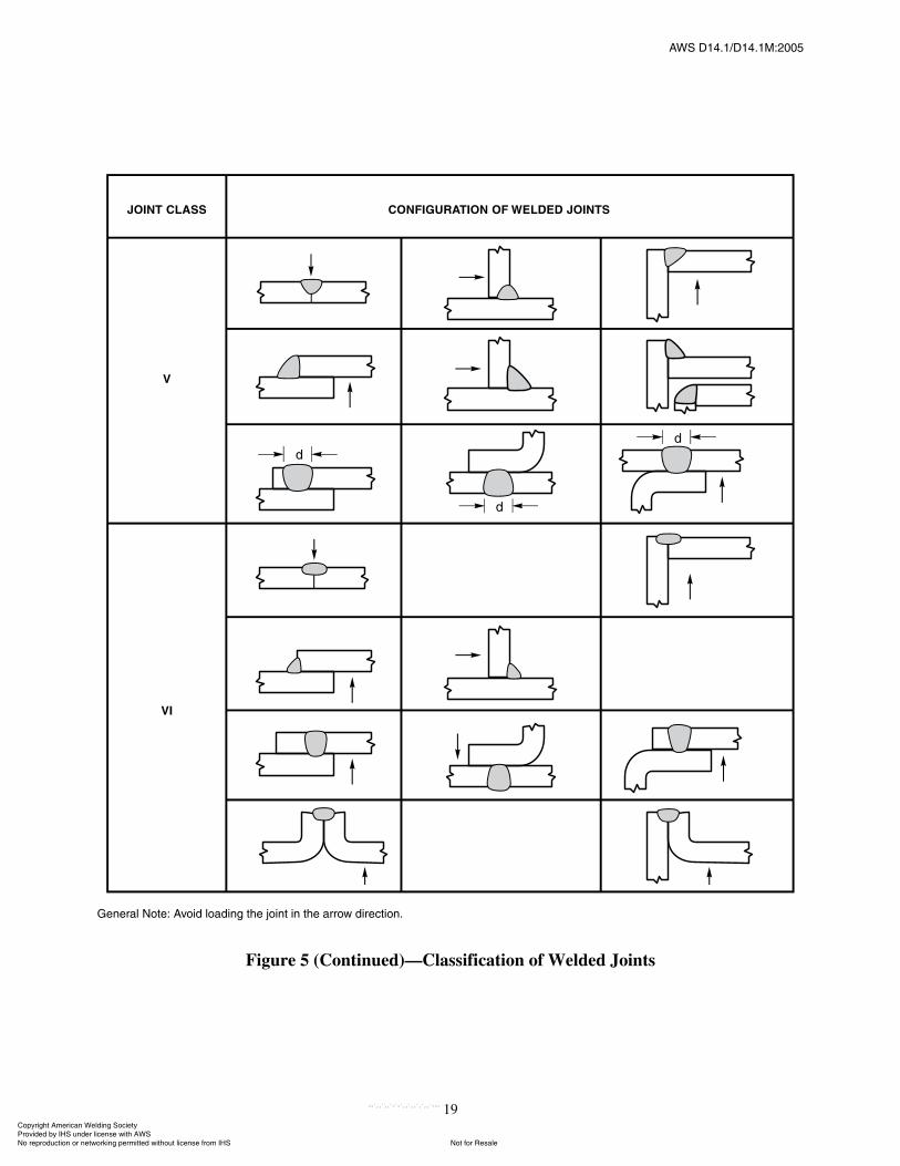
ßÉÍ ÜïìòïñÜïìòïÓæîððë
19
Ù»²»®¿´ Ò±¬»æ ߪ±·¼ ´±¿¼·²¹ ¬¸» ¶±·²¬ ·² ¬¸» ¿®®±© ¼·®»½¬·±²ò
Figure 5 (Continued)�Classification of Welded Joints
ݱ°§®·¹¸¬ ß³»®·½¿² É»´¼·²¹ ͱ½·»¬§ Ю±ª·¼»¼ ¾§ ×ØÍ «²¼»® ´·½»²» ©·¬¸ ßÉÍ
Ò±¬ º±® λ¿´»Ò± ®»°®±¼«½¬·±² ±® ²»¬©±®µ·²¹ °»®³·¬¬»¼ ©·¬¸±«¬ ´·½»²» º®±³ ×ØÍ
óóÀôôÀôôÀóÀóÀôôÀôôÀôÀôôÀóóó

ßÉÍ ÜïìòïñÜïìòïÓæîððë
20
6.9 Weld Joint Classes
6.9.1 Joint Class I. Joints in this class are double-welded butt joints with complete joint penetration. Theroot of the first weld is chipped, gouged, or ground tosound metal before making the second weld, and theweld faces are ground or machined flush with the direc-tion of metal removal parallel to the principle stress.Welded joints that are made using backing tape, fusibleflux backing material, or a nonfusible backing bar, andare back welded to obtain a completely fused root, shallbe qualified in accordance with Section 9, Qualification.Finished joints shall be nondestructively examinedaccording to Section 10, Weld Quality and Inspection,and the results recorded.
6.9.2 Joint Class II. Joints in this class are double-welded butt, T-, and corner joints with complete jointpenetration. The root of the first weld is chipped,gouged, or ground to sound metal before making the sec-ond weld. Welded joints that are made using backingtape, fusible flux backing material, or a nonfusible back-ing bar, and are back welded to obtain a completelyfused root, shall be qualified in accordance with Section9, Qualification. Finished joints shall be nondestructivelyexamined according to Section 10, Weld Quality andInspection, and the results recorded.
6.9.3 Joint Class III. Joints in this class are completejoint penetration butt, T-, and corner joints welded fromboth sides, or from one side using a backing strip that isnot removed after welding.
6.9.4 Joint Class IV. Joints in this class are completejoint penetration butt, T-, and corner joints welded fromone side without the use of backing; partial joint penetra-tion butt, T-, and corner joints welded on both sides; andfillet welded lap, T-, and corner joints welded on bothsides.
6.9.5 Joint Class V. Joints in this class are partialjoint penetration butt, T-, and corner joints welded onone side; and fillet, plug, or slot welded lap, T-, andcorner joints welded on one side only.
6.9.6 Joint Class VI. Joints in this class are jointswhich do not require special weld groove preparation,such as butt, T-, corner, lap, or edge joints; plug welds;welds of secondary importance in strength; and structuralwelded joints of secondary importance not subject todynamic loading.
6.10 Joint Qualification
6.10.1 Joints meeting the following requirements aredesignated as prequalified:
(1) Conformance with the details of 6.2 through 6.7,and Figures I.1 or I.2 in Annex I; and
(2) Welded with one of the following processes in ac-cordance with the requirements of Section 8, Processesand Filler Metals, as applicable: shielded metal arc, sub-merged arc, flux cored arc, and gas metal arc with otherthan short-circuiting transfer.
6.10.2 Other joint configurations may be usedwith proper qualification in accordance with Section 9,Qualification.
6.11 Transition of Thicknesses or Widths at ButtJoints
6.11.1 Butt joints between parts of unequal thick-nesses and also subject to tensile stress shall have asmooth transition between the offset surfaces at a maxi-mum slope of 1 in 2-1/2 with the adjacent surface ofeither part. The transition may be accomplished by slop-ing the weld face(s), by chamfering the thicker part, orby a combination of the two methods (see Figure 6).
6.11.2 Transition of thickness in butt joints betweenparts of unequal thickness, that are subject only to shearor compressive stress, shall be accomplished as specifiedin 6.11.1 when the offset between surfaces at either sideof the joint is greater than the thickness of the thinnerpart connected. When the offset does not exceed thethickness of the thinner part connected, the face of theweld shall be sloped (1) no more than 1 in 2-1/2 from thesurface of the thinner part or (2) to the surface of thethicker part if this requires a lesser slope. The exceptionis that truss member joints and beam and girder flangejoints shall be made with a smooth transition of the typespecified in 6.11.1.
6.11.3 Butt joints between parts of unequal widththat are subject to tensile stress shall have either (1) asmooth slope between offset edges of no more than 1 in2-1/2 with the edge of either part or (2) a 2.0 ft[600 mm] minimum radius tangent to the narrower partat the center of the butt joint, as shown in Figure 7. Aradius transition is required for steels having yieldstrength greater than or equal to 90 ksi [620 MPa].
6.12 Material for Joint Extensions, Backing, andSpacers
6.12.1 Material for joint extensions and backing usedin welding shall conform to the following requirements:
(1) When used for welding any prequalified steellisted in 4.4, they may be of any of the steels in the samelist.
(2) When used for welding with a steel qualified inaccordance with this specification, they shall be of thesteel qualified.
(3) Use 100 ksi [690 MPa] minimum yield strengthsteel when and only when welding 100 ksi [690 MPa]minimum yield strength steels.
ݱ°§®·¹¸¬ ß³»®·½¿² É»´¼·²¹ ͱ½·»¬§ Ю±ª·¼»¼ ¾§ ×ØÍ «²¼»® ´·½»²» ©·¬¸ ßÉÍ
Ò±¬ º±® λ¿´»Ò± ®»°®±¼«½¬·±² ±® ²»¬©±®µ·²¹ °»®³·¬¬»¼ ©·¬¸±«¬ ´·½»²» º®±³ ×ØÍ
óóÀôôÀôôÀóÀóÀôôÀôôÀôÀôôÀóóó
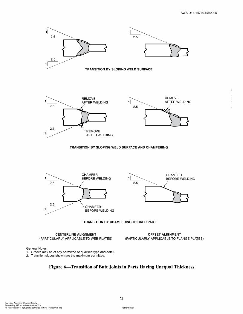
ßÉÍ ÜïìòïñÜïìòïÓæîððë
21
Ù»²»®¿´ Ò±¬»æïò Ù®±±ª» ³¿§ ¾» ±º ¿²§ °»®³·¬¬»¼ ±® ¯«¿´·º·»¼ ¬§°» ¿²¼ ¼»¬¿·´òîò Ì®¿²·¬·±² ´±°» ¸±©² ¿®» ¬¸» ³¿¨·³«³ °»®³·¬¬»¼ò
Figure 6�Transition of Butt Joints in Parts Having Unequal Thickness
ݱ°§®·¹¸¬ ß³»®·½¿² É»´¼·²¹ ͱ½·»¬§ Ю±ª·¼»¼ ¾§ ×ØÍ «²¼»® ´·½»²» ©·¬¸ ßÉÍ
Ò±¬ º±® λ¿´»Ò± ®»°®±¼«½¬·±² ±® ²»¬©±®µ·²¹ °»®³·¬¬»¼ ©·¬¸±«¬ ´·½»²» º®±³ ×ØÍ
óóÀôôÀôôÀóÀóÀôôÀôôÀôÀôôÀóóó
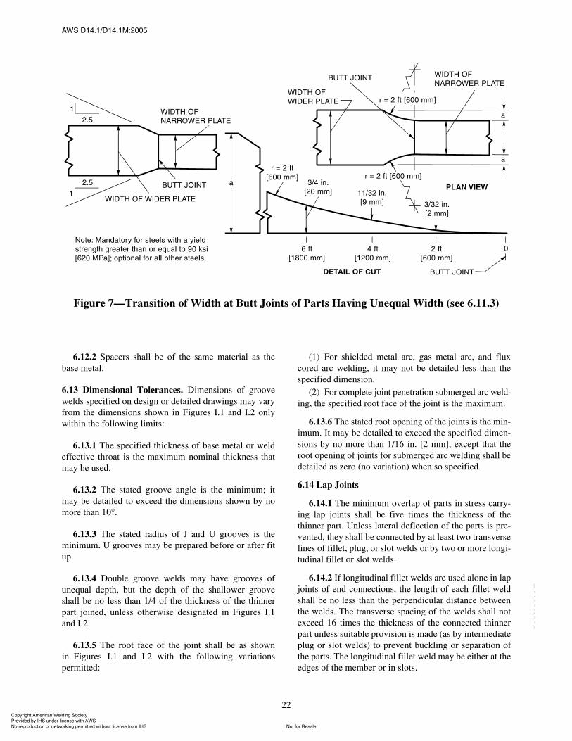
ßÉÍ ÜïìòïñÜïìòïÓæîððë
22
6.12.2 Spacers shall be of the same material as thebase metal.
6.13 Dimensional Tolerances. Dimensions of groovewelds specified on design or detailed drawings may varyfrom the dimensions shown in Figures I.1 and I.2 onlywithin the following limits:
6.13.1 The specified thickness of base metal or weldeffective throat is the maximum nominal thickness thatmay be used.
6.13.2 The stated groove angle is the minimum; itmay be detailed to exceed the dimensions shown by nomore than 10°.
6.13.3 The stated radius of J and U grooves is theminimum. U grooves may be prepared before or after fitup.
6.13.4 Double groove welds may have grooves ofunequal depth, but the depth of the shallower grooveshall be no less than 1/4 of the thickness of the thinnerpart joined, unless otherwise designated in Figures I.1and I.2.
6.13.5 The root face of the joint shall be as shownin Figures I.1 and I.2 with the following variationspermitted:
(1) For shielded metal arc, gas metal arc, and fluxcored arc welding, it may not be detailed less than thespecified dimension.
(2) For complete joint penetration submerged arc weld-ing, the specified root face of the joint is the maximum.
6.13.6 The stated root opening of the joints is the min-imum. It may be detailed to exceed the specified dimen-sions by no more than 1/16 in. [2 mm], except that theroot opening of joints for submerged arc welding shall bedetailed as zero (no variation) when so specified.
6.14 Lap Joints
6.14.1 The minimum overlap of parts in stress carry-ing lap joints shall be five times the thickness of thethinner part. Unless lateral deflection of the parts is pre-vented, they shall be connected by at least two transverselines of fillet, plug, or slot welds or by two or more longi-tudinal fillet or slot welds.
6.14.2 If longitudinal fillet welds are used alone in lapjoints of end connections, the length of each fillet weldshall be no less than the perpendicular distance betweenthe welds. The transverse spacing of the welds shall notexceed 16 times the thickness of the connected thinnerpart unless suitable provision is made (as by intermediateplug or slot welds) to prevent buckling or separation ofthe parts. The longitudinal fillet weld may be either at theedges of the member or in slots.
Figure 7�Transition of Width at Butt Joints of Parts Having Unequal Width (see 6.11.3)
ݱ°§®·¹¸¬ ß³»®·½¿² É»´¼·²¹ ͱ½·»¬§ Ю±ª·¼»¼ ¾§ ×ØÍ «²¼»® ´·½»²» ©·¬¸ ßÉÍ
Ò±¬ º±® λ¿´»Ò± ®»°®±¼«½¬·±² ±® ²»¬©±®µ·²¹ °»®³·¬¬»¼ ©·¬¸±«¬ ´·½»²» º®±³ ×ØÍ
óóÀôôÀôôÀóÀóÀôôÀôôÀôÀôôÀóóó
ßÉÍ ÜïìòïñÜïìòïÓæîððë
23
6.14.3 When fillet welds in holes or slots are used, theclear distance from the edge of the hole or slot to theadjacent edge of the part containing it, measured perpen-dicular to the direction of stress, shall be no less than fivetimes the thickness of the part nor less than two times thewidth of the hole or slot. The strength of the part shall bedetermined from the critical net section of the basemetal.
6.15 Corner and T-Joints. Corner and T-joints that areto be subjected to bending about an axis parallel to thejoint shall have their welds arranged to avoid concentra-tion of tensile stress at the root of any weld.
6.16 Welds in Combination with Rivets and Bolts.Rivets or bolts used in bearing-type connections shall notbe considered as sharing the load in combination withwelds. Welds, if used, shall be provided to carry theentire load in the connection. High-strength bolts prop-erly installed as a slip-critical-type connection prior towelding may be considered as sharing the load with thewelds. Bolts or rivets used in assembly may be left inplace if their removal is not specified. If bolts are to beremoved, the plans should indicate whether holes shouldbe filled and in what manner.
6.17 Eccentricity of Connections
6.17.1 Eccentricity between intersecting parts andmembers shall be avoided insofar as practicable.
6.17.2 In designing welded joints, adequate provisionshall be made for bending stresses due to eccentricity, ifany, in the disposition and section of base-metal partsand in the location and types of welded joints.
6.17.3 For members having symmetrical cross sec-tions, the connection welds shall be arranged symmetri-cally about the axis of the member, or proper allowanceshall be made for unsymmetrical distribution of stresses.
6.17.4 For axially stressed angle members, the centerof gravity of the connecting welds shall lie between theline of the center of gravity of the angle�s cross sectionand the centerline of the connected leg. If the center ofgravity of the connecting weld lies outside of this zone,the total stresses, including those due to the eccentricityfrom the center of gravity of the angle, shall not exceedthose permitted by this specification.
7. Workmanship7.1 General
7.1.1 All requirements of this section shall beobserved in the production and inspection of welded
assemblies produced by any of the processes acceptableunder this specification.
7.1.2 All welding and thermal-cutting equipment shallbe so designed and manufactured, and shall be in suchcondition, as to enable designated personnel to followthe procedures and attain the results described elsewherein this specification.
7.1.3 Welding shall not be done when the ambienttemperature is lower than 0°F [�18°C], when surfacesare wet or exposed to rain, snow, or high wind velocities,or when welding personnel are exposed to inclementconditions. The maximum permissible wind velocity willvary with the welding process and procedure. Heating,local protection from the elements, or both, shall be usedas necessary.
7.1.4 The size and length of welds shall not be lessthan those specified by design requirements and detaildrawings, except as permitted by 10.6(6), nor shall theyexceed those requirements by more than 25% withoutprior approval of the design change by the responsibleEngineer. Also, the location of welds shall not bechanged without prior approval of the Design Engineer.
7.2 Preparation of the Base Metal
7.2.1 Surfaces and edges to be welded shall besmooth, uniform, and free from fins, tears, cracks, andother visual defects that would adversely affect the qual-ity of the weld. Surfaces to be welded and surfaces adja-cent to a weld shall be free from loose or thick mill scale,slag, rust, paint, moisture, and other foreign material, orcontaminants that will prevent proper welding or pro-duce hazardous fumes. Thin mill scale (that can with-stand vigorous wire brushing), thin rust-inhibitivecoating, or antispatter compound (that will not causeproblems with welding) need not be removed.
7.2.2 When oxyfuel gas cutting is employed, the cut-ting torch shall be adjusted and manipulated to avoid cut-ting beyond (inside) the prescribed lines. The roughnessof cut surfaces shall not be greater than Sample No. 2 ofAWS C4.1, Surface Roughness Gauge, for materialthicknesses up to 2 in. [50 mm], and Sample No. 1 formaterial 2 in. [50 mm] to 8 in. [200 mm] thick. Surfacesexceeding the above roughness values and occasionalnotches or gouges not exceeding 3/16 in. [5 mm] deepshall be corrected by machining or grinding. Notches orother sharp discontinuities exceeding 3/16 in. [5 mm]may be repaired by welding only with the approval of theDesign Engineer. Approved weld repairs shall be madeonly by following a documented repair welding proce-dure that shall contain the following:
(1) Discontinuity removal and joint preparation.(2) Welding process and filler metal to be used.
ݱ°§®·¹¸¬ ß³»®·½¿² É»´¼·²¹ ͱ½·»¬§ Ю±ª·¼»¼ ¾§ ×ØÍ «²¼»® ´·½»²» ©·¬¸ ßÉÍ
Ò±¬ º±® λ¿´»Ò± ®»°®±¼«½¬·±² ±® ²»¬©±®µ·²¹ °»®³·¬¬»¼ ©·¬¸±«¬ ´·½»²» º®±³ ×ØÍ
óóÀôôÀôôÀóÀóÀôôÀôôÀôÀôôÀóóó
ßÉÍ ÜïìòïñÜïìòïÓæîððë
24
(3) Preheat and welding variables and also anypostheat requirements necessary to comply with thisspecification.
(4) Procedures for grinding the completed weldsmooth and flush to within the surface roughness accep-tance criteria of 7.2.2. Weld repaired surfaces and edgesthat will not be subsequently incorporated into a weldingjoint shall be stress relieved by any approved methodwhen determined necessary by the Design Engineer.
7.2.3 Machining, plasma arc cutting, air carbon arccutting, oxyfuel gas cutting, oxygen gouging, chipping,or grinding may be used for joint preparation, back goug-ing, and the removal of unacceptable work or metal. Oneexception is that oxygen gouging shall not be used onquenched and tempered steel. Thermally cut surfacesshould be ground as needed to proper contour. Prepara-tion of nonferrous base metals by nontraditional methodsshall be a matter of agreement between the Manufacturerand Owner.
7.2.4 Edges of built up beam and girder webs shall becut to the prescribed camber with empirically developedmanufacturing allowance for shrinkage due to cuttingand welding. However, deviation from the specifiedcamber tolerances may be corrected by carefully super-vised application of a limited amount of localized heat orother suitable means of obtaining the specified camber.
The use of flame straightening of distorted membersand camber correction by localized heating shall have theapproval of the Design Engineer and follow an approvedwritten procedure (see 12.4). When flame straighteningis used, the temperature of the heated areas shall be accu-rately measured. The temperature shall not exceed1100°F [590°C] for quenched and tempered steels ornormalized and tempered steels, and 1200°F [650°C] forother steels.
7.2.5 Dimensional Tolerances. Dimensions of builtup beams and girders shall be within the tolerance of thegeneral specification governing the work, and alsowithin the following special tolerances. All measure-ments shall be taken at the Manufacturer�s plant prior toshipment, unless otherwise specified.
7.2.5.1 Maximum deviation from straightness, Ds ,(referenced to the neutral axis) of welded beams or gird-ers, where there is no specified sweep:
Ds , in. = 0.0125 I total length, ft
Ds , mm = 1.04 I total length, m
7.2.5.2 Maximum deviation from specified camber(in the service position), Dc, of welded beam or girders:
Dc, in. = ±0.003 I total length, ft, or ±1/4 in, which-ever is greater
Dc, mm = ±0.25 I total length, m, or ±6 mm, which-ever is greater
7.2.5.3 Lateral deviation between the centerline ofthe web and the centerline of the flange of buildup H or Imembers at the contact surface (referenced to neutralaxis) shall be 1/4 in. [6 mm] maximum.
7.2.5.4 The maximum deviation from the specifieddepth for welded built up beams and girders, measured atthe web centerline, shall be ±1/2 in. [13 mm] for depthsup to 72 in. [1800 mm]. For depths over 72 in. [1800mm], the maximum deviation shall be +3/4 in. [20 mm]to �1/2 in. [13 mm].
7.2.6 Re-entrant corners, except for the corners ofweld-access cope holes adjacent to a flange, shall be fil-leted to a radius of no less than 3/4 in. [20 mm]. The filletand its adjacent cuts shall meet without offset or cuttingpast the point of tangency.
7.3 Visual Inspection and Repair of Plate andWrought Steel Products
7.3.1 In the repair and the determination of the limitsof visible internal discontinuities on rolled, sheared, oroxygen cut edges, the amount of metal removed shall bethe minimum necessary to remove the discontinuity, butnot to exceed the permissible limit given in Table 7.Material cut edges may exist at any angle with respect tothe rolling direction. All repairs of discontinuities bywelding shall conform to the applicable provisions ofthis specification.
7.3.2 The limits of acceptability and the repair ofvisually observed edge discontinuities shall be in accor-dance with Table 7. The length of discontinuity is thevisible length dimension on the material edge, and thedepth is the distance that the discontinuity extends intothe material from the edge.
7.3.3 Discontinuities over 1 in. [25 mm] in length andin depth, when discovered during either visual inspectionof cut surfaces or nondestructive examination of weldedjoints, shall be evaluated further. The following proce-dures are recommended:
(1) Where discontinuities, such as W, X, or Y in Fig-ure 8 are observed prior to completing the joint, the sizeand shape of discontinuity shall be determined by ultra-sonic inspection. The area of the discontinuity shall bedetermined as the area of total loss of back reflectionwhen examined in accordance with the procedure sectionof ASTM A 435.
(2) For acceptance of W, X, or Y discontinuities, thearea of a single discontinuity or the aggregate area of
ݱ°§®·¹¸¬ ß³»®·½¿² É»´¼·²¹ ͱ½·»¬§ Ю±ª·¼»¼ ¾§ ×ØÍ «²¼»® ´·½»²» ©·¬¸ ßÉÍ
Ò±¬ º±® λ¿´»Ò± ®»°®±¼«½¬·±² ±® ²»¬©±®µ·²¹ °»®³·¬¬»¼ ©·¬¸±«¬ ´·½»²» º®±³ ×ØÍ
óóÀôôÀôôÀóÀóÀôôÀôôÀôÀôôÀóóó

ßÉÍ ÜïìòïñÜïìòïÓæîððë
25
multiple discontinuities shall not exceed 4% of the cutmaterial area (length I width) with the following excep-tion: if the width of discontinuity or the aggregate widthof discontinuities on any transverse section, as measuredperpendicular to the cut material length, exceeds 20% ofthe cut material width, the maximum allowable area shallbe reduced by the percentage amount of the widthexceeding 20%. For example, if a discontinuity is 30% ofthe cut material width, the percentage area of discontinu-
ity cannot exceed 4 minus 4 I (0.30�0.20), or 3.6% ofthe cut material area. The discontinuity on the edge ofthe plate shall be gouged out to a depth of 1 in. [25 mm]beyond its intersection with the surface by chipping, aircarbon arc gouging, or grinding, and then blocked off bywelding in layers not exceeding 1/8 in. [3 mm] in thick-ness for at least the first four layers.
(3) Repair of an internal discontinuity, Z, in Figure 8is not required if it does not exceed the allowable area in7.3.3(2), is discovered after the joint has been completed,and is 1 in. [25 mm] or more from the toe of the weld asmeasured on the cut material surface. If a Type Z discon-tinuity is less than 1 in. [25 mm] from the face of theweld, it shall be removed to a distance of 1 in. [25 mm]from the fusion zone of the weld by chipping, gouging orgrinding. It shall then be blocked by welding in layersnot exceeding 1/8 in. [3 mm] in thickness for at least thefirst four layers.
(4) If the area of the discontinuity W, X, Y, or Zexceeds the allowable in 7.3.3(2), the cut material or sub-component shall be either rejected and replaced orrepaired at the discretion of the Design Engineer.
(5) The aggregate length of weld repair shall notexceed 30% of the length of the cut surface withoutapproval of the Design Engineer.
(6) All repairs shall be in accordance with this speci-fication. Gouging of a discontinuity may be done fromeither the cut material surface or the edge.
7.4 Assembly
7.4.1 Parts to be joined by fillet welds shall bebrought as close together as practicable at the joint. Rootcracking may occur in a fillet weld if there is no rootopening between the parts (e.g., surfaces machined to
Ì¿¾´» éÔ·³·¬ ±² ß½½»°¬¿¾·´·¬§ ¿²¼ λ°¿·® ±º Û¼¹» Ü·½±²¬·²«·¬·» ·² Ý«¬ Í«®º¿½» ø»» éòíòî÷
Size of Discontinuity
Repair RequiredLength, in. [mm] Depth, in. [mm]
1 [25]> 1 [25]> 1 [25]> 1 [25]> 1 [25]
Unspecified 1/8 [3]
> 1/8 [3] to 1/4 [6]> 1/4 [6] to 1 [25]> 1 [25]
None; need not be explored.None; depth should be explored per Note (1).Remove; repair welding not required.Completely remove and repair weld as limited by Note (2).Refer to 7.3.3.
Notes:(1) A spot check of 10% of the discontinuities on the edge in question should be explored by grinding to determine depth. If the depth of any one of the
discontinuities explored exceeds 1/8 [3 mm], then all of the discontinuities remaining on that edge shall be explored by grinding to determinedepth. If none of the discontinuities explored in the 10% spot check has a depth exceeding 1/8 in. [3 mm], then the remaining of the discontinuitieson that edge need not be explored.
(2) Aggregate length of welding shall not exceed 20% of the length of the plate edge being repaired.
Figure 8�Edge Discontinuitiesin Cut Material (see 7.3.3)
ݱ°§®·¹¸¬ ß³»®·½¿² É»´¼·²¹ ͱ½·»¬§ Ю±ª·¼»¼ ¾§ ×ØÍ «²¼»® ´·½»²» ©·¬¸ ßÉÍ
Ò±¬ º±® λ¿´»Ò± ®»°®±¼«½¬·±² ±® ²»¬©±®µ·²¹ °»®³·¬¬»¼ ©·¬¸±«¬ ´·½»²» º®±³ ×ØÍ
óóÀôôÀôôÀóÀóÀôôÀôôÀôÀôôÀóóó
ßÉÍ ÜïìòïñÜïìòïÓæîððë
26
bear). It may be necessary to provide a small root open-ing, in such cases, prior to welding. In any case, the rootopening between parts shall not exceed 1/8 in. [3 mm]for sections up to 2 in. [50 mm] in thickness. When theroot opening between shapes or plates of 2 in. [50 mm]or more in thickness cannot be closed to meet this toler-ance, a maximum root opening of 3/16 in. [5 mm] is ac-ceptable if a sealing weld or suitable backing material6 isused. If the root opening is 1/16 in. [2 mm] or greater, theleg of the fillet weld shall be increased by the amount ofthe separation, or the contractor shall demonstrate thatthe required effective throat has been obtained.
The separation between the faying surfaces of lapjoints and butt joints with a backing shall not exceed1/16 in. [2 mm]. Deviations from these limits shall beapproved by the Design Engineer.
7.4.2 Parts to be joined by partial joint penetrationgroove welds parallel to the length of the member (bear-ing joints excepted) shall be brought as close together aspracticable. The root opening between parts shall notexceed 1/8 in. [3 mm]. If the root opening between rolledshapes or plates of 2 in. [50 mm] or greater in thicknesscannot be closed sufficiently to meet this tolerance, amaximum gap of 3/16 in. [5 mm] is acceptable provided(1) a sealing weld or suitable backing material is usedand (2) the final weld meets the requirements for effec-tive throat. Tolerances for bearing joints shall be inaccordance with the applicable contract specification orthe Manufacturer�s standard if no tolerances are includedin the contract. Deviations from these limits shall beapproved by the Design Engineer.
7.4.3 Parts to be joined at butt joints shall be carefullyaligned. Where the parts are effectively restrainedagainst bending due to eccentricity in alignment, an off-set not exceeding 10% of the thickness of the thinner partjoined, but in no case more than 0.18 in. [4.5 mm], maybe permitted as a departure from the theoretical align-ment. In correcting misalignment in such cases, the slopeof the drawn-in parts shall not exceed 1 to 24. Measure-ment of offset shall be based upon centerline of parts,unless otherwise shown on the drawing. Deviations fromthese limits shall be approved by the Design Engineer.
7.4.4 Dimensions of the cross section of groove weldjoint preparations that vary from those shown on thedetail drawings by more than the tolerances given inTable 8 shall be referred to the Design Engineer foracceptance. Exceptions are grooves for electroslag andelectrogas welds.
6. Backing may be flux, glass tape, iron powder, or similarmaterials. Sealant (root) passes should be made with low-hydrogen covered electrodes or other arc welding processes.
7.4.5 Grooves produced by gouging shall be in accor-dance with the requirements for processes and fillermetals of Section 8.
7.4.6 Groove welds shall be terminated at the ends ofa joint in a manner that will ensure sound welds. Thisshould be done by the use of extension bars or run-offplates.
7.4.7 Extension bars and run-off plates shall beremoved upon completion of the welding, and the endsof the weld shall be finished smooth and flush with theedges of the abutting parts.
7.4.8 The weld metal of groove welds made with steelbacking strips shall be thoroughly fused with the back-ing. Steel backings shall be removed, where accessible,from welds that are transverse to computed stress, andthe joints shall be ground or finished smooth.
7.4.9 Members to be welded shall be brought into cor-rect alignment and held in position by clamps, wedges,guy lines, struts, tack welds, or other suitable devicesuntil welding has been completed. The use of jigs andfixtures is recommended where practicable. Suitableallowances shall be made for warpage and shrinkage.
7.4.10 Steel backing shall be continuous for the fulllength of a weld. Welded butt joints in a fabricated steelbacking shall have complete joint penetration, and thejoints shall be welded prior to placement of the backing.
7.4.11 Caulking of welds is not permitted.
7.4.12 Tack Welds
7.4.12.1 Tack welds shall be subject to the samequality requirements as the final welds.
Ì¿¾´» è̱´»®¿²½» º±® Ù®±±ª» É»´¼ Ö±·²¬
Ю»°¿®¿¬·±² º±® ß®½ É»´¼·²¹ ø»» éòìòì÷
Root Not Gouged Root Gouged
in. mm in. mm
Root face ±1/16 ±2 Not limited
Root opening with other than steel backing
±1/16 ±2 ±1/16 ±2
Root opening with steel backing
+1/4 +6 Not applicable
Groove angle +5° +10°, �5°
ݱ°§®·¹¸¬ ß³»®·½¿² É»´¼·²¹ ͱ½·»¬§ Ю±ª·¼»¼ ¾§ ×ØÍ «²¼»® ´·½»²» ©·¬¸ ßÉÍ
Ò±¬ º±® λ¿´»Ò± ®»°®±¼«½¬·±² ±® ²»¬©±®µ·²¹ °»®³·¬¬»¼ ©·¬¸±«¬ ´·½»²» º®±³ ×ØÍ
óóÀôôÀôôÀóÀóÀôôÀôôÀôÀôôÀóóó
ßÉÍ ÜïìòïñÜïìòïÓæîððë
27
7.4.12.2 Tack welds which are incorporated intothe final weld shall be made with electrodes meeting therequirements of the final weld. Multipass tack weldsshall have cascaded ends. Tack welds shall be cleanedprior to depositing additional weld metal.
7.4.12.3 Tack welds not incorporated into finalwelds shall be removed.
7.4.13 Arc Strikes. Arc strikes outside the area ofpermanent welds should be avoided on any base metal.Cracks or blemishes caused by arc strikes shall beground to a smooth contour and examined to ensuresoundness (see 12.2.2).
7.5 Control of Distortion and Shrinkage Stresses
7.5.1 The procedure and welding sequence for assem-bling and joining parts of a structure or of built up mem-bers and for welding reinforcing parts to members, shallbe designed to minimize distortion and shrinkage.
7.5.2 When practicable, all welds shall be deposited ina sequence that will balance the applied heat while weld-ing progresses.
7.5.3 A program for welding sequence and distortioncontrol shall be provided where shrinkage stresses or dis-tortion are likely to affect the adequacy of the structure.
7.5.4 Joints that are expected to produce large shrink-age should usually be welded with as little restraint aspossible before other joints that are expected to causeless shrinkage are welded.
7.5.5 Peening may be used on intermediate weld lay-ers for control of shrinkage stresses in thick welds to pre-vent cracking (see 7.8). No peening shall be done on theroot pass. Peening of the final weld layer shall be forfatigue enhancement purposes only and shall be doneaccording to an approved written procedure (see 7.8.3).
7.5.6 In making welds under conditions of severeexternal shrinkage restraint, the welding shall be carriedcontinuously to completion or to a point that will ensurefreedom from cracking before the joint is allowed to coolbelow the minimum specified preheat temperature.Where preheat and interpass temperatures are not speci-fied, welding shall continue to a point where freedomfrom cracking is assured.
7.6 Stress Relief. Where required by the contract draw-ings or specifications, welded assemblies shall be stressrelieved.
7.6.1 All stress relief operations shall follow anapproved written procedure.
7.6.2 Localized stress relieving may be employed,subject to approval by the Design Engineer, when it is
impractical to stress relieve the entire weldment. A writ-ten procedure shall address the variables given in 7.6.3.
7.6.3 The procedures for furnace stress relief shalladdress the following:
(1) Temperature at the start of the thermal cycle.(2) Rate of heating to temperature.(3) Maximum allowable variation of temperature
throughout the portion of the part being heated.(4) Maximum temperature tolerance at stress relief
temperature.(5) Holding time at stress relief temperature.(6) Rate of cooling to a temperature suitable for
removal of work from the furnace.(7) The thermocouples shall have surface contact
with the weldment and be shielded from direct impinge-ment of the heat source. The records shall include thelocation, calibration and thermal chart of each thermo-couple, along with traceable weldment documentation.The records and data shall become part of the weldmentdocumentation.
(8) Support of the weldment to minimize sagging anddistortion.
(9) Spacing of multiple items so all pieces will heatuniformly.
(10) Use of baffles or insulating material to protect theweldment from direct impingement of the heat source.
7.6.4 Stress relieving of weldments of A514, A517,A709 Grades 100 and 100W, and A710 steels is not rec-ommended. Stress relieving may be necessary for thoseapplications where weldments must retain dimensionalstability during machining or where stress corrosion maybe involved, neither condition being unique to weld-ments involving A514, A517, A709 Grades 100 and100W, and A710 steels. However, the results of notchtoughness tests have shown that stress relieving mayactually impair weld metal toughness, and intergranularcracking may sometimes occur in the grain-coarsenedregion of the weld heat affected zone. Such steels shouldonly be stress relieved after consultation with the steelproducer and in strict accordance with the producer�srecommendations.
Precautionary Note: Consideration must be given topossible distortion due to stress relief.
7.7 Vibratory Conditioning
7.7.1 Vibratory conditioning to obtain dimensionalstability of the weldment may be employed with theapproval of the Engineer. The conditioning shall be donein accordance with the recommendations of the manufac-turer of the vibratory equipment. It shall not be substi-tuted for thermal stress relief.
ݱ°§®·¹¸¬ ß³»®·½¿² É»´¼·²¹ ͱ½·»¬§ Ю±ª·¼»¼ ¾§ ×ØÍ «²¼»® ´·½»²» ©·¬¸ ßÉÍ
Ò±¬ º±® λ¿´»Ò± ®»°®±¼«½¬·±² ±® ²»¬©±®µ·²¹ °»®³·¬¬»¼ ©·¬¸±«¬ ´·½»²» º®±³ ×ØÍ
óóÀôôÀôôÀóÀóÀôôÀôôÀôÀôôÀóóó
ßÉÍ ÜïìòïñÜïìòïÓæîððë
28
7.7.2 The conditioning process shall be covered by awritten procedure.
7.8 Peening. Shot and mechanical peening provide forimproved fatigue life in the weld joint as a result of thesurface material being placed in compression.7, 8, 9
Mechanical peening can be applied to intermediate weldpasses to reduce residual stresses, cracking, and distor-tion. All peening shall be done using an approved writtenprocedure. These guidelines are based on experiencewith carbon steel.
7.8.1 Controlled Shot Peening. Controlled shotpeening may be used on external surfaces to improvefatigue life. Controlled shot peening procedures shallinclude Almen intensity, shot size, pressure, and percentcoverage.
7.8.2 Hammer Peening. Hammer peening may beused on external surfaces to improve fatigue life. Peen-ing should be controlled to prevent introducing stressconcentrations to, or cracking of, the weld or base metal.Controlled air hammer peening procedures shall specifyhammer size, peening tool radius, air pressure, andextent and density of coverage (see 7.8.4).
7.8.3 Peening Applications(1) No peening shall be done on the root pass.(2) Hammer or needle peening may be used on inter-
mediate weld layers for control of shrinkage stresses inthick welds to prevent cracking.
(3) Peening of the surface layer of the weld and thebase metal at the edges of the weld is permitted forfatigue life improvement. Under controlled conditions,both shot and mechanical peening places the exposedmaterial in compression which reduces residual tensilestresses at the weld surface, the toe of the weld, and thebase metal adjacent to the weld.
(4) All slag shall be removed prior to peening. Theuse of manual slag hammers, chisels, and lightweighttools such as needle descaling guns for the removal of slagand spatter is permitted, but is not considered peening.
7.8.4 Specification for Pneumatic Hammer Peen-ing for Fatigue Life Improvement. Peening of weldtoes shall be performed with the use of a small pneumatichammer (Ingersoll #2 or equivalent) and peening tool asshown in Figure 9(A). All welds shall pass magnetic par-
7. Bremen, U., Smith, I. F. C., and Hirt, M. A., Crack GrowthBehavior in a Welded Joint Improved by Residual StressMethod. International Conference: Fatigue of Welded Con-struction, Ed., Maddox, S. J. The Welding Institute: 1987.8. Booth, G. S., Improving the Fatigue Performance of WeldedJoints. The Welding Institute: 1983.9. Metal Improvement Company, Inc. Shot Peening Applica-tion, Seventh Edition.
ticle examination prior to peening, followed by a secondmagnetic particle examination after peening.
The peening tool shall be made from a chisel or othertool designed for the pneumatic hammer. The tool tipshall conform to the dimensions shown in Figure 9(A).All sharp edges and burrs shall be removed and the toolshape maintained in this geometric shape and condition.
Best peening results will be obtained by operating thepneumatic hammer at approximately 25 psi [1.7 bar] airpressure. The axis of the hammer shall be perpendicularto the longitudinal axis of the weld toe and inclined 60°to 70° above the weld toe plane as shown in Figure 9(B).Peening is done by slowly moving the peening tool of anoperating hammer along the weld toe. Peening shall con-tinue until the weld toe becomes smooth (absence ofweld ripples), approximately three to four passes at30 in./min [760 mm/min]. The depth of indentation dueto peening should be approximately 1/32 in. [1 mm] to1/16 in. [2 mm].
Peened welds, after passing the second magnetic par-ticle examination, have increased fatigue strength equalto the next higher stress category (see Table 3) for theapplicable detail (see Table 4 and Figure 1). However,the stress category for peened welds shall not exceedcategory B.
8. Processes and Filler Metals8.1 General
8.1.1 Filler Metal Requirements
8.1.1.1 The electrode, electrode-flux combination,or other filler metal for making complete joint penetra-tion groove welds shall be in accordance with Table 9when matching weld metal is required by Table 2.
8.1.1.2 The electrode, electrode-flux combination,or other filler metal for complete joint penetration or par-tial joint penetration groove welds and for fillet weldsmay provide lower strength weld metal, as permitted inTable 2. The allowable stress in the weld metal shall notexceed that allowed in Table 2.
8.1.2 Preheat and Interpass Temperature Require-ments. Preheat and interpass temperatures shall be inaccordance with Table 10 for the welding process beingused and for the higher strength base metals beingwelded.
8.1.3 Heat Input Control for Quenched and Tem-pered Steel. When quenched and tempered steels arewelded, the heat input shall be restricted in conjunctionwith the maximum preheat and interpass temperaturespermitted for the metal thickness. The heat input limita-tions shall be in accordance with the steel producer�s rec-
ݱ°§®·¹¸¬ ß³»®·½¿² É»´¼·²¹ ͱ½·»¬§ Ю±ª·¼»¼ ¾§ ×ØÍ «²¼»® ´·½»²» ©·¬¸ ßÉÍ
Ò±¬ º±® λ¿´»Ò± ®»°®±¼«½¬·±² ±® ²»¬©±®µ·²¹ °»®³·¬¬»¼ ©·¬¸±«¬ ´·½»²» º®±³ ×ØÍ
óóÀôôÀôôÀóÀóÀôôÀôôÀôÀôôÀóóó
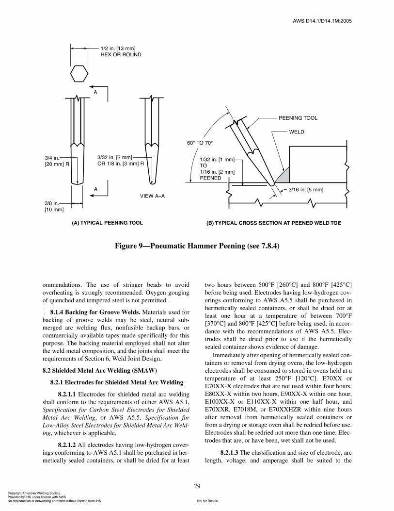
ßÉÍ ÜïìòïñÜïìòïÓæîððë
29
ommendations. The use of stringer beads to avoidoverheating is strongly recommended. Oxygen gougingof quenched and tempered steel is not permitted.
8.1.4 Backing for Groove Welds. Materials used forbacking of groove welds may be steel, neutral sub-merged arc welding flux, nonfusible backup bars, orcommercially available tapes made specifically for thispurpose. The backing material employed shall not alterthe weld metal composition, and the joints shall meet therequirements of Section 6, Weld Joint Design.
8.2 Shielded Metal Arc Welding (SMAW)
8.2.1 Electrodes for Shielded Metal Arc Welding
8.2.1.1 Electrodes for shielded metal arc weldingshall conform to the requirements of either AWS A5.1,Specification for Carbon Steel Electrodes for ShieldedMetal Arc Welding, or AWS A5.5, Specification forLow-Alloy Steel Electrodes for Shielded Metal Arc Weld-ing, whichever is applicable.
8.2.1.2 All electrodes having low-hydrogen cover-ings conforming to AWS A5.1 shall be purchased in her-metically sealed containers, or shall be dried for at least
two hours between 500°F [260°C] and 800°F [425°C]before being used. Electrodes having low-hydrogen cov-erings conforming to AWS A5.5 shall be purchased inhermetically sealed containers, or shall be dried for atleast one hour at a temperature of between 700°F[370°C] and 800°F [425°C] before being used, in accor-dance with the recommendations of AWS A5.5. Elec-trodes shall be dried prior to use if the hermeticallysealed container shows evidence of damage.
Immediately after opening of hermetically sealed con-tainers or removal from drying ovens, the low-hydrogenelectrodes shall be consumed or stored in ovens held at atemperature of at least 250°F [120°C]. E70XX orE70XX-X electrodes that are not used within four hours,E80XX-X within two hours, E90XX-X within one hour,E100XX-X or E110XX-X within one half hour, andE70XXR, E7018M, or E70XXHZR within nine hoursafter removal from hermetically sealed containers orfrom a drying or storage oven shall be redried before use.Electrodes shall be redried not more than one time. Elec-trodes that are, or have been, wet shall not be used.
8.2.1.3 The classification and size of electrode, arclength, voltage, and amperage shall be suited to the
Figure 9�Pneumatic Hammer Peening (see 7.8.4)
ݱ°§®·¹¸¬ ß³»®·½¿² É»´¼·²¹ ͱ½·»¬§ Ю±ª·¼»¼ ¾§ ×ØÍ «²¼»® ´·½»²» ©·¬¸ ßÉÍ
Ò±¬ º±® λ¿´»Ò± ®»°®±¼«½¬·±² ±® ²»¬©±®µ·²¹ °»®³·¬¬»¼ ©·¬¸±«¬ ´·½»²» º®±³ ×ØÍ
óóÀôôÀôôÀóÀóÀôôÀôôÀôÀôôÀóóó
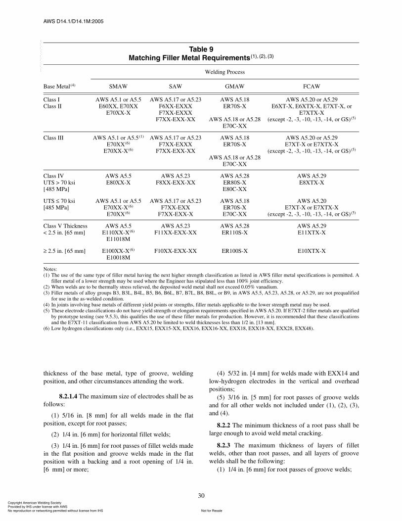
ßÉÍ ÜïìòïñÜïìòïÓæîððë
30
thickness of the base metal, type of groove, weldingposition, and other circumstances attending the work.
8.2.1.4 The maximum size of electrodes shall be asfollows:
(1) 5/16 in. [8 mm] for all welds made in the flatposition, except for root passes;
(2) 1/4 in. [6 mm] for horizontal fillet welds;
(3) 1/4 in. [6 mm] for root passes of fillet welds madein the flat position and groove welds made in the flatposition with a backing and a root opening of 1/4 in.[6 mm] or more;
(4) 5/32 in. [4 mm] for welds made with EXX14 andlow-hydrogen electrodes in the vertical and overheadpositions;
(5) 3/16 in. [5 mm] for root passes of groove weldsand for all other welds not included under (1), (2), (3),and (4).
8.2.2 The minimum thickness of a root pass shall belarge enough to avoid weld metal cracking.
8.2.3 The maximum thickness of layers of filletwelds, other than root passes, and all layers of groovewelds shall be the following:
(1) 1/4 in. [6 mm] for root passes of groove welds;
Ì¿¾´» çÓ¿¬½¸·²¹ Ú·´´»® Ó»¬¿´ λ¯«·®»³»²¬øï÷ô øî÷ô øí÷
Base Metal(4)
Welding Process
SMAW SAW GMAW FCAW
Class IClass II
AWS A5.1 or A5.5E60XX, E70XX
E70XX-X
AWS A5.17 or A5.23F6XX-EXXXF7XX-EXXX
F7XX-EXX-XX
AWS A5.18ER70S-X
AWS A5.18 or A5.28E70C-XX
AWS A5.20 or A5.29E6XT-X, E6XTX-X, E7XT-X, or
E7XTX-X(except -2, -3, -10, -13, -14, or GS)(5)
Class III AWS A5.1 or A5.5(1)
E70XX(6)
E70XX-X(6)
AWS A5.17 or A5.23F7XX-EXXX
F7XX-EXX-XX
AWS A5.18ER70S-X
AWS A5.18 or A5.28E70C-XX
AWS A5.20 or A5.29E7XT-X or E7XTX-X
(except -2, -3, -10, -13, -14, or GS)(5)
Class IVUTS > 70 ksi[485 MPa]
AWS A5.5E80XX-X
AWS A5.23F8XX-EXX-XX
AWS A5.28ER80S-XE80C-XX
AWS A5.29E8XTX-X
UTS 70 ksiÅ485 MPa]
AWS A5.1 or A5.5E70XX-X(6)
E70XX(6)
AWS A5.17 or A5.23F7XX-EXX
F7XX-EXX-X
AWS A5.18ER70S-XE70C-XX
AWS A5.20E7XT-X or E7XTX-X
(except -2, -3, -10, -13, -14, or GS)(5)
Class V Thickness< 2.5 in. [65 mm]
AWS A5.5E110XX-X(6)
E11018M
AWS A5.23F11XX-EXX-XX
AWS A5.28ER110S-X
AWS A5.29E11XTX-X
2.5 in. [65 mm] E100XX-X(6)
E10018MF10XX-EXX-XX ER100S-X E10XTX-X
Notes:(1) The use of the same type of filler metal having the next higher strength classification as listed in AWS filler metal specifications is permitted. A
filler metal of a lower strength may be used where the Engineer has stipulated less than 100% joint efficiency.(2) When welds are to be thermally stress relieved, the deposited weld metal shall not exceed 0.05% vanadium.(3) Filler metals of alloy groups B3, B3L, B4L, B5, B6, B6L, B7, B7L, B8, B8L, or B9, in AWS A5.5, A5.23, A5.28, or A5.29, are not prequalified
for use in the as-welded condition.(4) In joints involving base metals of different yield points or strengths, filler metals applicable to the lower strength metal may be used.(5) These electrode classifications do not have yield strength or elongation requirements specified in AWS A5.20. If E7XT-2 filler metals are qualified
by prototype testing (see 9.5.3), this qualifies the use of these filler metals for production. However, it is recommended that these classificationsand the E7XT-11 classification from AWS A5.20 be limited to weld thicknesses less than 1/2 in. [13 mm].
(6) Low hydrogen classifications only (i.e., EXX15, EXX15-XX, EXX16, EXX16-XX, EXX18, EXX18-XX, EXX28, EXX48).
ݱ°§®·¹¸¬ ß³»®·½¿² É»´¼·²¹ ͱ½·»¬§ Ю±ª·¼»¼ ¾§ ×ØÍ «²¼»® ´·½»²» ©·¬¸ ßÉÍ
Ò±¬ º±® λ¿´»Ò± ®»°®±¼«½¬·±² ±® ²»¬©±®µ·²¹ °»®³·¬¬»¼ ©·¬¸±«¬ ´·½»²» º®±³ ×ØÍ
óóÀôôÀôôÀóÀóÀôôÀôôÀôÀôôÀóóó
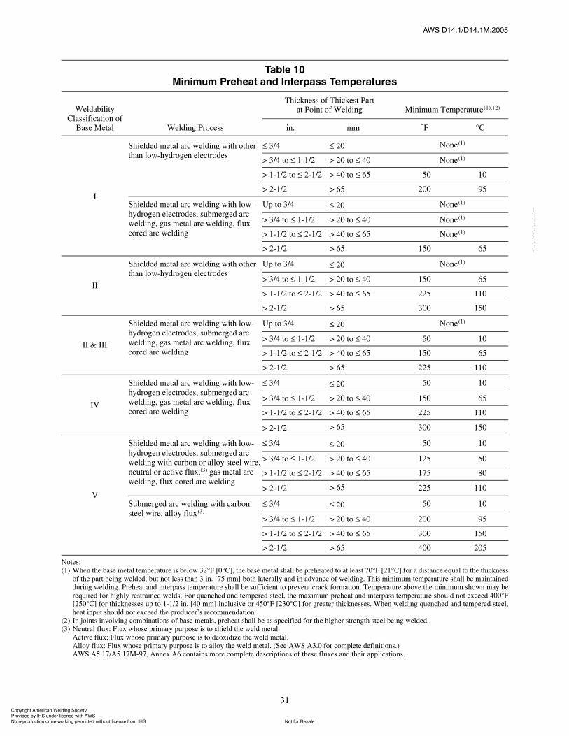
ßÉÍ ÜïìòïñÜïìòïÓæîððë
31
Ì¿¾´» ïðÓ·²·³«³ Ю»¸»¿¬ ¿²¼ ײ¬»®°¿ Ì»³°»®¿¬«®»
Weldability Classification of
Base Metal Welding Process
Thickness of Thickest Partat Point of Welding Minimum Temperature (1), (2)
in. mm °F °C
I
Shielded metal arc welding with other than low-hydrogen electrodes
3/4 20 None(1)
> 3/4 to 1-1/2 > 20 to 40 None(1)
> 1-1/2 to 2-1/2 > 40 to 65 50 10
> 2-1/2 > 65 200 95
Shielded metal arc welding with low-hydrogen electrodes, submerged arc welding, gas metal arc welding, flux cored arc welding
Up to 3/4 20 None(1)
> 3/4 to 1-1/2 > 20 to 40 None(1)
> 1-1/2 to 2-1/2 > 40 to 65 None(1)
> 2-1/2 > 65 150 65
II
Shielded metal arc welding with other than low-hydrogen electrodes
Up to 3/4 20 None(1)
> 3/4 to 1-1/2 > 20 to 40 150 65
> 1-1/2 to 2-1/2 > 40 to 65 225 110
> 2-1/2 > 65 300 150
II & III
Shielded metal arc welding with low-hydrogen electrodes, submerged arc welding, gas metal arc welding, flux cored arc welding
Up to 3/4 20 None(1)
> 3/4 to 1-1/2 > 20 to 40 50 10
> 1-1/2 to 2-1/2 > 40 to 65 150 65
> 2-1/2 > 65 225 110
IV
Shielded metal arc welding with low-hydrogen electrodes, submerged arc welding, gas metal arc welding, flux cored arc welding
3/4 20 50 10
> 3/4 to 1-1/2 > 20 to 40 150 65
> 1-1/2 to 2-1/2 > 40 to 65 225 110
> 2-1/2 > 65 300 150
V
Shielded metal arc welding with low-hydrogen electrodes, submerged arc welding with carbon or alloy steel wire, neutral or active flux,(3) gas metal arc welding, flux cored arc welding
3/4 20 50 10
> 3/4 to 1-1/2 > 20 to 40 125 50
> 1-1/2 to 2-1/2 > 40 to 65 175 80
> 2-1/2 > 65 225 110
Submerged arc welding with carbon steel wire, alloy flux(3)
3/4 20 50 10
> 3/4 to 1-1/2 > 20 to 40 200 95
> 1-1/2 to 2-1/2 > 40 to 65 300 150
> 2-1/2 > 65 400 205
Notes:(1) When the base metal temperature is below 32°F [0°C], the base metal shall be preheated to at least 70°F [21°C] for a distance equal to the thickness
of the part being welded, but not less than 3 in. [75 mm] both laterally and in advance of welding. This minimum temperature shall be maintainedduring welding. Preheat and interpass temperature shall be sufficient to prevent crack formation. Temperature above the minimum shown may berequired for highly restrained welds. For quenched and tempered steel, the maximum preheat and interpass temperature should not exceed 400°F[250°C] for thicknesses up to 1-1/2 in. [40 mm] inclusive or 450°F [230°C] for greater thicknesses. When welding quenched and tempered steel,heat input should not exceed the producer�s recommendation.
(2) In joints involving combinations of base metals, preheat shall be as specified for the higher strength steel being welded.(3) Neutral flux: Flux whose primary purpose is to shield the weld metal.
Active flux: Flux whose primary purpose is to deoxidize the weld metal.Alloy flux: Flux whose primary purpose is to alloy the weld metal. (See AWS A3.0 for complete definitions.)AWS A5.17/A5.17M-97, Annex A6 contains more complete descriptions of these fluxes and their applications.
ݱ°§®·¹¸¬ ß³»®·½¿² É»´¼·²¹ ͱ½·»¬§ Ю±ª·¼»¼ ¾§ ×ØÍ «²¼»® ´·½»²» ©·¬¸ ßÉÍ
Ò±¬ º±® λ¿´»Ò± ®»°®±¼«½¬·±² ±® ²»¬©±®µ·²¹ °»®³·¬¬»¼ ©·¬¸±«¬ ´·½»²» º®±³ ×ØÍ
óóÀôôÀôôÀóÀóÀôôÀôôÀôÀôôÀóóó

ßÉÍ ÜïìòïñÜïìòïÓæîððë
32
(2) 1/8 in. [3 mm] for subsequent layers of weldsmade in the flat position;
(3) 3/16 in. [5 mm] for subsequent layers of weldsmade in the vertical, overhead, and horizontal positions.
8.2.4 The maximum size of both single-pass and root-pass fillet welds shall be the following:
(1) 3/8 in. [10 mm] in the flat position;(2) 5/16 in. [8 mm] in horizontal and overhead
positions;(3) 1/2 in. [13 mm] in the vertical position.
8.2.5 The progression of welding in the vertical posi-tion may be upward or downward, but only in the direc-tion or directions for which the welder is qualified.
8.2.6 Complete joint penetration groove welds thatare made without the use of steel backing shall have theroot of the first weld gouged or ground to sound metalbefore the second weld is started on the opposite side.
8.3 Submerged Arc Welding (SAW)
8.3.1 General Requirements
8.3.1.1 Submerged arc welding (SAW) may beperformed with one or more single electrodes, one ormore parallel electrodes, or combinations of single andparallel electrodes. The spacing between multiple arcsshall be such that the slag cover over the weld metal pro-duced by a leading arc does not cool sufficiently to pre-vent proper fusion of the weld metal deposit from afollowing electrode. SAW with multiple electrodes maybe used for any groove or fillet weld pass.
8.3.1.2 The following subsections (8.3.1.3 through8.3.1.7) governing the use of SAW are suitable for anysteel included in Table 1, other than quenched and tem-pered steels. Concerning welding of quenched and tem-pered steels, it is necessary to comply with the steelproducer�s recommendations for maximum permissibleheat input and preheat combinations. Such consider-ations shall include the additional heat input produced insimultaneous welding on two sides of a common member.
8.3.1.3 The size of the electrode shall not exceed1/4 in. [6 mm] diameter.
8.3.1.4 Surfaces on which submerged arc welds areto be deposited and adjacent faying surfaces shall beclean and free of moisture and other contaminants thatmay have an adverse effect on weld quality.
8.3.1.5 Roots of groove or fillet welds may bebacked with copper, flux, glass tape, iron powder, orsimilar materials to prevent melt-through, or be sealed bymeans of root passes deposited using a low-hydrogenwelding procedure. Use caution to avoid letting thewelding arc strike the copper backing.
8.3.1.6 Neither the depth nor the maximum widthin the cross section of the weld metal deposited in eachweld pass shall exceed the width of the face of that weldpass or throat cracking may occur (see Figure 10).
8.3.1.7 Tack welds located in the roots of jointsrequiring specific root penetration, or in the form of filletwelds 3/8 in. [10 mm] and under in size, shall not pro-duce objectionable changes in appearance of the weldsurface or result in decreased penetration. Tack weldsthat will cause unsatisfactory weld characteristics shallbe reduced in size by any suitable means before welding.Tack welds in the root of a joint with steel backing ofless than 5/16 in. [8 mm] thick shall either be reduced insize by any suitable means before welding or madecontinuous for the full length of the joint using a low-hydrogen welding procedure. After any tack weld isreduced in size, care shall be taken to clean the weldgroove before proceeding.
8.3.2 Electrodes and Fluxes. The electrode and fluxcombination used for submerged arc welding of a steel
Figure 10�Unacceptable SubmergedArc Weld Pass where the Depth and
Width Exceed the Face Width
ݱ°§®·¹¸¬ ß³»®·½¿² É»´¼·²¹ ͱ½·»¬§ Ю±ª·¼»¼ ¾§ ×ØÍ «²¼»® ´·½»²» ©·¬¸ ßÉÍ
Ò±¬ º±® λ¿´»Ò± ®»°®±¼«½¬·±² ±® ²»¬©±®µ·²¹ °»®³·¬¬»¼ ©·¬¸±«¬ ´·½»²» º®±³ ×ØÍ
óóÀôôÀôôÀóÀóÀôôÀôôÀôÀôôÀóóó
ßÉÍ ÜïìòïñÜïìòïÓæîððë
33
shall conform to the requirements of AWS A5.17, Speci-fication for Carbon Steel Electrodes and Fluxes for Sub-merged Arc Welding or of AWS A5.23, Specification forLow Alloy Steel Electrodes and Fluxes for SubmergedArc Welding, whichever is applicable.
8.3.3 Condition of Flux. Flux used for SAW shall bedry and free of contamination from dirt, mill scale, orother foreign material. Flux shall be purchased in pack-ages that can be stored under normal conditions for atleast six months without affecting the welding character-istics of the flux or the weld properties. Flux from dam-aged packages shall be discarded or dried at a minimumtemperature of 250°F [120°C] for one hour before use.Flux shall be placed in the dispensing system immedi-ately upon opening a package. Before using flux that hasbeen exposed to the atmosphere in an open package, thetop 1 in. [25 mm] shall be discarded. Flux that has beenwet shall not be used.
SAW flux that has not been melted during the weld-ing operation may be reused after recovery by vacuum-ing, catch pans, sweeping, or other means. The weldingfabricator shall have a system for collecting unmeltedflux, adding new flux, and welding with the mixture ofthese two, such that the flux composition and particlesize distribution at the weld puddle are relatively con-stant. Recrushed slag may be used provided it has itsown marking, using the recrusher�s name and trade des-ignation. In addition, each dry batch or dry blend (lot) offlux, as defined in AWS A5.01, Filler Metal Procure-ment Guidelines, shall be tested in conformance withSchedule I of AWS A5.01 and classified by the contrac-tor or recrusher per AWS A5.17 or A5.23, as applicable.
8.3.4 Procedures for SAW with a Single Electrode
8.3.4.1 Submerged arc welds may be made ineither the flat or horizontal position. Single-pass filletwelds made in the horizontal position shall not exceed5/16 in. [8 mm] in size.
8.3.4.2 The thickness of weld layers, except rootand surface layers, shall not exceed 1/4 in. [6 mm].When the root opening is 1/2 in. [13 mm] or greater, amultiple-pass stringer bead (split layer) technique shallbe used. The stringer bead (split layer) technique shallalso be used in making multiple-pass welds when thewidth of the layer will exceed 5/8 in. [16 mm].
8.3.4.3 The welding conditions, including current,arc voltage, and speed of travel, shall ensure that eachweld pass will have complete fusion with the adjacentbase and weld metals, and have no overlap or unaccept-able undercut. The maximum welding current used tomake any weld pass with fusion to both faces of a weldgroove shall be 800 A, except that the final layer of weldmetal may be made using higher welding current. The
maximum welding current to be used for fillet welds inthe flat position shall be 1000 A.
8.3.5 Procedures for SAW with Multiple Electrodes
8.3.5.1 Submerged arc welds made with multipleelectrodes may be made in either the flat or horizontalposition. Single-pass, multiple-arc fillet welds made inthe horizontal position shall not exceed 1/2 in. [13 mm]in size.
8.3.5.2 The thickness of weld layers is not limited.In making the root pass of a groove weld, either single ormultiple electrodes may be used. Backing strips or rootfaces of the groove shall be of adequate thickness to pre-vent melt-through. When the width of a groove in whicha layer of weld metal is to be deposited exceeds 1/2 in.[13 mm], multiple electrodes shall be displaced laterally,or a stringer bead (split layer) technique shall be used toassure complete fusion. A stringer bead (split layer) tech-nique shall be employed when only two electrodes intandem are used and the width of a previously depositedlayer exceeds 1 in. [25 mm].
8.3.5.3 The welding conditions, including current,arc voltage, speed of travel, and relative location of elec-trodes, shall ensure that each pass will have completefusion with the adjacent base and weld metals, and haveno depressions or unacceptable undercut. Concavity ofinitial weld passes shall not be excessive to avoid crack-ing in roots of joints that are under restraint.
8.3.5.4 The maximum welding current used inmaking a groove weld shall be as limited by the allow-able heat input for quenched and tempered materials. Forother materials, the following limitations shall apply:
(1) 700 A for any single electrode or for multipleelectrodes when making a root pass of a multiple-passweld in a groove having no root opening.
(2) 750 A for any single electrode or 900 A for multi-ple electrodes when making a root pass in a groovehaving steel backing or a spacer bar.
(3) 1000 A for any single electrode or 1200 A formultiple electrodes for all other passes except the rootpass and the final layer.
(4) Any suitable amperage for the final pass or layer.
8.3.5.5 The maximum welding current to be usedwhen making a fillet weld shall be 1000 A for a singleelectrode or 1200 A for multiple electrodes or as limitedby the allowable heat input for quenched and temperedmaterials.
8.3.5.6 Multiple electrodes may be used in the rootof groove or fillet welds using a leading gas metal arcelectrode with gas shielding followed by multiple sub-merged arc electrodes provided that (1) the gas metal arcwelding conforms to the requirements of 8.4, and (2) the
ݱ°§®·¹¸¬ ß³»®·½¿² É»´¼·²¹ ͱ½·»¬§ Ю±ª·¼»¼ ¾§ ×ØÍ «²¼»® ´·½»²» ©·¬¸ ßÉÍ
Ò±¬ º±® λ¿´»Ò± ®»°®±¼«½¬·±² ±® ²»¬©±®µ·²¹ °»®³·¬¬»¼ ©·¬¸±«¬ ´·½»²» º®±³ ×ØÍ
óóÀôôÀôôÀóÀóÀôôÀôôÀôÀôôÀóóó
ßÉÍ ÜïìòïñÜïìòïÓæîððë
34
spacing between the leading gas metal arc electrode andthe first following submerged arc electrode is not morethan 15 in. [375 mm].
8.4 Gas Metal Arc Welding (GMAW) and Flux CoredArc Welding (FCAW)
8.4.1 Consumables
8.4.1.1 The electrodes and shielding medium forgas metal arc welding (GMAW) or flux cored arc weld-ing (FCAW) for producing weld metal with a minimumspecified yield strength of 60 ksi [415 MPa] or less shallconform to the requirements of AWS A5.18, Specifica-tion for Carbon Steel Electrodes and Rods for GasShielded Arc Welding, AWS A5.20, Specification forCarbon Steel Electrodes for Flux Cored Arc Welding, orAWS A5.29, Specification for Low Alloy Steel Elec-trodes for Flux Cored Arc Welding, as applicable.
8.4.1.2 Weld metal having a minimum specifiedyield strength greater than 60 ksi [415 MPa] shall con-form to the following requirements:
(1) The electrodes and shielding gas for GMAW forproducing weld metal with a minimum specified yieldstrength greater than 60 ksi [415 MPa] shall conformwith AWS A5.28, Specification for Low-Alloy SteelFiller Metals for Gas Shielded Arc Welding.
(2) The electrodes and shielding gas for flux coredarc welding for producing weld metal with a minimumspecified yield strength greater than 60 ksi [415 MPa]shall conform to AWS A5.29, Specification for LowAlloy Steel Electrodes for Flux Cored Arc Welding.
8.4.1.3 When requested by the Design Engineer,the fabricator shall furnish the electrode manufacturer�scertification that the filler metal product being used metthe requirements for classification in accordance with theapplicable AWS specifications. The electrode manufac-turer�s recommended welding process conditions andparameters including amperage, voltage and shieldinggas (or lack of such) shall be followed.
8.4.2 Shielding Gas. When a gas or gas mixture isused for shielding in any gas shielded process, it shall bea welding grade having a dew point of �40°F [�40°C] orlower (see AWS A5.32, Specification for WeldingShielding Gases).
8.4.3 Prequalified Procedures for GMAW10 andFCAW. The requirements for prequalified proceduresthat are exempt from qualification testing are as follows:
10. Applies only when welding with the spray or globularmodes of metal transfer. Prequalification does not apply toshort-circuiting metal transfer.
8.4.3.1 Electrodes shall be dry and in suitable con-dition for use.
8.4.3.2 The maximum diameter of electrodes shallbe 1/8 in. [3 mm] for the flat and horizontal positions,and 5/64 in. [2 mm] for the vertical and overheadpositions.
8.4.3.3 The maximum size of a fillet weld made inone pass shall be 1/2 in. [13 mm] for the flat and verticalpositions, 3/8 in. [10 mm] for the horizontal position, and5/16 in. [8 mm] for the overhead position.
8.4.3.4 The maximum fill pass thickness shall be1/4 in. [6 mm]. The maximum root pass thickness shallbe 3/8 in. [10 mm] for the flat position, 5/16 in. [8 mm]for the horizontal and overhead positions, and 1/2 in.[13 mm] for the vertical position. The stringer bead(split layer) technique shall also be used in making allmultipass welds (fillet or groove) when the width of thepreceding layer exceeds 5/8 in. [16 mm].
8.4.3.5 The welding conditions used shall ensurethat each pass will have complete fusion with adjacentbase metal and weld metal, and there will be no exces-sive overlap, porosity, or undercutting.
8.4.3.6 Complete joint penetration groove weldsmade without the use of steel backing shall have the rootof the first weld gouged to sound metal before the secondweld is started from the opposite side of the joint.
8.4.3.7 Backing may be used to prevent melt-through at the roots of fillet welds and partial penetrationgroove welds.
8.4.3.8 Welding with external gas shielding shallnot be done in a draft or wind having a velocity exceed-ing five miles per hour unless the weld is protected by ashelter. The shelter shall reduce the air velocity in thevicinity of the welding to that necessary to avoid loss ofgas shielding.
8.5 Electroslag Welding (ESW) and Electrogas Weld-ing (EGW)
8.5.1 General Requirements
8.5.1.1 Electroslag Welding (ESW) and electrogaswelding (EGW) of quenched and tempered steels is notpermitted unless the heat-affected zone (HAZ) and weldare heat treated subsequent to welding to obtain therequired mechanical properties.
8.5.1.2 Prior to use, the Manufacturer shall preparea welding procedure specification and qualify each pro-cedure for the process to be used in accordance with therequirements of Section 9, Qualification. The weldingprocedure specification shall include the joint details,filler metal type and diameter, welding current and type,
ݱ°§®·¹¸¬ ß³»®·½¿² É»´¼·²¹ ͱ½·»¬§ Ю±ª·¼»¼ ¾§ ×ØÍ «²¼»® ´·½»²» ©·¬¸ ßÉÍ
Ò±¬ º±® λ¿´»Ò± ®»°®±¼«½¬·±² ±® ²»¬©±®µ·²¹ °»®³·¬¬»¼ ©·¬¸±«¬ ´·½»²» º®±³ ×ØÍ
óóÀôôÀôôÀóÀóÀôôÀôôÀôÀôôÀóóó
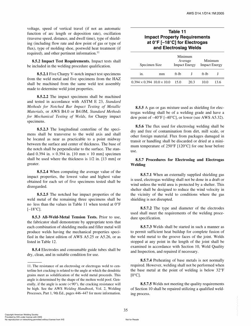
ßÉÍ ÜïìòïñÜïìòïÓæîððë
35
voltage, speed of vertical travel (if not an automaticfunction of arc length or deposition rate), oscillation(traverse speed, distance, and dwell time), type of shield-ing (including flow rate and dew point of gas or type offlux), type of molding shoe, postweld heat treatment (ifrequired), and other pertinent information.11
8.5.2 Impact Test Requirements. Impact tests shallbe included in the welding procedure qualification.
8.5.2.1 Five Charpy V-notch impact test specimensfrom the weld metal and five specimens from the HAZshall be machined from the same weld test assemblymade to determine weld joint properties.
8.5.2.2 The impact specimens shall be machinedand tested in accordance with ASTM E 23, StandardMethods for Notched Bar Impact Testing of MetallicMaterials, or AWS B4.0 or B4.0M, Standard Methodsfor Mechanical Testing of Welds, for Charpy impactspecimens.
8.5.2.3 The longitudinal centerline of the speci-mens shall be transverse to the weld axis and shallbe located as near as practicable to a point midwaybetween the surface and center of thickness. The base ofthe notch shall be perpendicular to the surface. The stan-dard 0.394 in. I 0.394 in. [10 mm I 10 mm] specimenshall be used where the thickness is 1/2 in. [13 mm] orgreater.
8.5.2.4 When computing the average value of theimpact properties, the lowest value and highest valueobtained for each set of five specimens tested shall bedisregarded.
8.5.2.5 The notched bar impact properties of theweld metal of the remaining three specimens shall beno less than the values in Table 11 when tested at 0°F[�18°C].
8.5.3 All-Weld-Metal Tension Tests. Prior to use,the fabricator shall demonstrate by appropriate tests thateach combination of shielding media and filler metal willproduce welds having the mechanical properties speci-fied in the latest edition of AWS A5.25 or A5.26, or aslisted in Table 12.
8.5.4 Electrodes and consumable guide tubes shall bedry, clean, and in suitable condition for use.
11. The resistance of an electroslag or electrogas weld to cen-terline hot cracking is related to the angle at which the dendriticgrains meet as solidification of the weld metal proceeds. Thisangle is determined by the shape of the molten weld pool. Gen-erally, if the angle is acute (< 90°), the cracking resistance willbe high. See the AWS Welding Handbook, Vol. 2, WeldingProcesses, Part 1, 9th Ed., pages 446�447 for more information.
8.5.5 A gas or gas mixture used as shielding for elec-trogas welding shall be of a welding grade and have adew point of �40°F [�40°C], or lower (see AWS A5.32).
8.5.6 The flux used for electroslag welding shall bedry and free of contamination from dirt, mill scale, orother foreign material. Flux from packages damaged intransit or handling shall be discarded or dried at a mini-mum temperature of 250°F [120°C] for one hour beforeuse.
8.5.7 Procedures for Electroslag and ElectrogasWelding
8.5.7.1 When an externally supplied shielding gasis used, electrogas welding shall not be done in a draft orwind unless the weld area is protected by a shelter. Thisshelter shall be designed to reduce the wind velocity inthe vicinity of the weld to conditions where the gasshielding is not disrupted.
8.5.7.2 The type and diameter of the electrodesused shall meet the requirements of the welding proce-dure specification.
8.5.7.3 Welds shall be started in such a manner asto permit sufficient heat buildup for complete fusion ofthe weld metal to the groove faces of the joint. Weldsstopped at any point in the length of the joint shall beexamined in accordance with Section 10, Weld Qualityand Inspection, and repaired if necessary.
8.5.7.4 Preheating of base metals is not normallyrequired. However, welding shall not be performed whenthe base metal at the point of welding is below 32°F[0°C].
8.5.7.5 Welds not meeting the quality requirementsof Section 10 shall be repaired utilizing a qualified weld-ing process.
Ì¿¾´» ïï׳°¿½¬ Ю±°»®¬§ λ¯«·®»³»²¬
¿¬ ðpÚ Å�ïèpÝà º±® Û´»½¬®±¹¿¿²¼ Û´»½¬®±´¿¹ É»´¼
Specimen Size
Minimum Average
Impact EnergyMinimum
Impact Energy
in. mm ft-lb J ft-lb J
0.394 I 0.394 10.0 I 10.0 15.0 20.3 10.0 13.6
ݱ°§®·¹¸¬ ß³»®·½¿² É»´¼·²¹ ͱ½·»¬§ Ю±ª·¼»¼ ¾§ ×ØÍ «²¼»® ´·½»²» ©·¬¸ ßÉÍ
Ò±¬ º±® λ¿´»Ò± ®»°®±¼«½¬·±² ±® ²»¬©±®µ·²¹ °»®³·¬¬»¼ ©·¬¸±«¬ ´·½»²» º®±³ ×ØÍ
óóÀôôÀôôÀóÀóÀôôÀôôÀôÀôôÀóóó
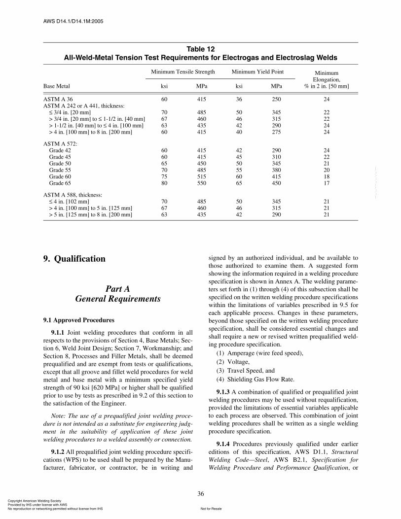
ßÉÍ ÜïìòïñÜïìòïÓæîððë
36
9. Qualification
Part AGeneral Requirements
9.1 Approved Procedures
9.1.1 Joint welding procedures that conform in allrespects to the provisions of Section 4, Base Metals; Sec-tion 6, Weld Joint Design; Section 7, Workmanship; andSection 8, Processes and Filler Metals, shall be deemedprequalified and are exempt from tests or qualifications,except that all groove and fillet weld procedures for weldmetal and base metal with a minimum specified yieldstrength of 90 ksi [620 MPa] or higher shall be qualifiedprior to use by tests as prescribed in 9.2 of this section tothe satisfaction of the Engineer.
Note: The use of a prequalified joint welding proce-dure is not intended as a substitute for engineering judg-ment in the suitability of application of these jointwelding procedures to a welded assembly or connection.
9.1.2 All prequalified joint welding procedure specifi-cations (WPS) to be used shall be prepared by the Manu-facturer, fabricator, or contractor, be in writing and
signed by an authorized individual, and be available tothose authorized to examine them. A suggested formshowing the information required in a welding procedurespecification is shown in Annex A. The welding parame-ters set forth in (1) through (4) of this subsection shall bespecified on the written welding procedure specificationswithin the limitations of variables prescribed in 9.5 foreach applicable process. Changes in these parameters,beyond those specified on the written welding procedurespecification, shall be considered essential changes andshall require a new or revised written prequalified weld-ing procedure specification.
(1) Amperage (wire feed speed),(2) Voltage,(3) Travel Speed, and(4) Shielding Gas Flow Rate.
9.1.3 A combination of qualified or prequalified jointwelding procedures may be used without requalification,provided the limitations of essential variables applicableto each process are observed. This combination of jointwelding procedures shall be written as a single weldingprocedure specification.
9.1.4 Procedures previously qualified under earliereditions of this specification, AWS D1.1, StructuralWelding Code�Steel, AWS B2.1, Specification forWelding Procedure and Performance Qualification, or
Ì¿¾´» ïîß´´óÉ»´¼óÓ»¬¿´ Ì»²·±² Ì»¬ λ¯«·®»³»²¬ º±® Û´»½¬®±¹¿ ¿²¼ Û´»½¬®±´¿¹ É»´¼
Base Metal
Minimum Tensile Strength Minimum Yield Point MinimumElongation,
% in 2 in. [50 mm]ksi MPa ksi MPa
ASTM A 36ASTM A 242 or A 441, thickness:
3/4 in. [20 mm]> 3/4 in. [20 mm] to 1-1/2 in. [40 mm]> 1-1/2 in. [40 mm] to 4 in. [100 mm]> 4 in. [100 mm] to 8 in. [200 mm]
60
70676360
415
485460435415
36
50464240
250
345315290275
24
22222424
ASTM A 572:Grade 42Grade 45Grade 50Grade 55Grade 60Grade 65
606065707580
415415450485515550
424550556065
290310345380415450
242221201817
ASTM A 588, thickness: 4 in. [102 mm]
> 4 in. [100 mm] to 5 in. [125 mm]> 5 in. [125 mm] to 8 in. [200 mm]
706763
485460435
504642
345315290
212121
ݱ°§®·¹¸¬ ß³»®·½¿² É»´¼·²¹ ͱ½·»¬§ Ю±ª·¼»¼ ¾§ ×ØÍ «²¼»® ´·½»²» ©·¬¸ ßÉÍ
Ò±¬ º±® λ¿´»Ò± ®»°®±¼«½¬·±² ±® ²»¬©±®µ·²¹ °»®³·¬¬»¼ ©·¬¸±«¬ ´·½»²» º®±³ ×ØÍ
óóÀôôÀôôÀóÀóÀôôÀôôÀôÀôôÀóóó
ßÉÍ ÜïìòïñÜïìòïÓæîððë
37
Section IX of the ASME Boiler and Pressure VesselCode for equivalent welding shall be acceptable underthis specification, subject to the limitations of variablesin Section 9. In addition, Standard Welding ProcedureSpecifications (WPSs) published by the AWS Commit-tee on Welding Qualification are acceptable, subject tothe limitations of variables in Section 9. New qualifica-tions shall be made in accordance with the requirementsof this specification, or the latest edition of B2.1, subjectto the limitations of variables in Section 9.
9.2 Other Procedures. Except for those proceduresexempted in 9.1.1, joint welding procedures that areemployed in executing contract work under this specifi-cation shall be qualified prior to use by tests as pre-scribed in Part B of this section to the satisfaction of boththe Owner�s appointed representative and the Manufac-turer�s designated representative responsible for weld-ing. The Owner�s appointed representative should acceptevidence of previous qualification of any joint weldingprocedures to be employed.
9.3 Welders, Welding Operators, and Tack Welders
9.3.1 All welders, welding operators, and tack weld-ers to be employed to weld under this specification shallhave been qualified by tests as prescribed in Parts C, D,and E, respectively, of this section or by AWS B2.1.Owner�s representatives, at their discretion, shouldaccept evidence of previous qualification (to other indus-try-recognized codes or specifications) of the welders,welding operators, and tack welders to be employed. Asuggested form showing the information required isshown in Annex A.
9.3.2 Radiographic examination of a welder�s orwelding operator�s qualification test plate, or test pipe,may be made in lieu of the guided bend test prescribed inParts C and D of this section.
9.4 Qualification Responsibility. Each Manufacturer orcontractor shall conduct the tests required by this specifi-cation to qualify the welding procedures and the welders,welding operators, and tack welders who will use theseprocedures.
Part BProcedure Qualification
9.5 Qualification of Welding Procedures. To qualify awelding procedure by test weldments, the Manufacturershall choose testing according to 9.6 through 9.14 orprototype testing according to 9.5.3.
9.5.1 The following rules apply when it is necessaryto establish a welding procedure by qualification asrequired by 9.2 or the contract specifications, and theprocedure shall be recorded by the Manufacturer as awelding procedure specification.
9.5.1.1 Qualification of a welding procedure usinga steel that is listed in Table 1, but not in 9.5.1.2, and hasa minimum specified yield point of less than 50 ksi[345 MPa] shall qualify the procedure for welding anyother steel or combination of steels listed in the table thathave a minimum specified yield point equal to or lessthan that of the base metal used in the test.
9.5.1.2 Qualification of a welding procedure estab-lished with ASTM A 131, Grades AH, DH, or EH; A515; A 537, Class 1; A 572, Grade 42 through 50; or API5LX, Grade 42 shall be considered as procedure qualifi-cation for welding any other steel or combination ofsteels in this group, or other steels included in Table 1that have a lower minimum specified yield point.
9.5.1.3 Qualification of a welding procedure estab-lished with a base metal included in Section 4, BaseMetals, and having a minimum specified yield strengthgreater than 50 ksi [345 MPa] shall qualify the procedurefor welding only base metals of the same material speci-fication and grade or type that have the same minimumspecified yield strength as the base metal tested, the per-mitted reduction in yield strength for increased materialthickness being excepted. For example, a procedurequalified with a 1 in. [25 mm] thick, 100 ksi [690 MPa]yield strength base metal also qualifies for a 3 in.[75 mm] thick, 90 ksi [620 MPa] yield strength basemetal of the same material specification.
9.5.1.4 Qualification of a welding procedure estab-lished with a combination of base metals included inTable 1 of different minimum specified yield strengths,one of which is greater than 50 ksi [345 MPa], shall qual-ify the procedure for welding that high yield strengthbase metal to any other of those base metals that have aminimum specified yield strength equal to or less thanthat of the lower strength base metal used in the test.
9.5.1.5 The variables listed in 9.5.2 are essentialvariables of a joint welding procedure. In preparing theprocedure qualification record and the welding proce-dure specification, the Manufacturer or contractor shallreport the specific values for the essential variables in9.5.2. The suggested form for showing the informationrequired is shown in Annex A.
9.5.2 Limitations of Variables. The changes set forthin 9.5.2.1 through 9.5.2.5 shall be considered essentialchanges in a welding procedure. Any changes exceedingthe limitations thereof shall require establishment of a
ݱ°§®·¹¸¬ ß³»®·½¿² É»´¼·²¹ ͱ½·»¬§ Ю±ª·¼»¼ ¾§ ×ØÍ «²¼»® ´·½»²» ©·¬¸ ßÉÍ
Ò±¬ º±® λ¿´»Ò± ®»°®±¼«½¬·±² ±® ²»¬©±®µ·²¹ °»®³·¬¬»¼ ©·¬¸±«¬ ´·½»²» º®±³ ×ØÍ
óóÀôôÀôôÀóÀóÀôôÀôôÀôÀôôÀóóó
ßÉÍ ÜïìòïñÜïìòïÓæîððë
38
new procedure incorporating those changes by qualifica-tion. When a combination of welding processes is used,the variables applicable to each process shall apply.
9.5.2.1 Shielded Metal Arc Welding (SMAW). Achange in any of the following variables requires requali-fication of the WPS:
(1) A change increasing filler metal strength levels(for example, a change from E70XX(-X) to E80XX-X,but not vice versa).
(2) A change from a low-hydrogen electrode to anon-low-hydrogen electrode, but not vice versa.
(3) An increase in the diameter of the electrode usedover that called for in the welding procedure specifica-tion.
(4) A change of more than 15% above or below thespecified mean arc voltage or amperage for each sizeelectrode used.12
(5) For a specified welding groove, a change of morethan ±25% in the specified number of passes. If the areaof the groove is changed, it is also permissible to changethe number of passes in proportion to the change in area.
(6) A change in position in which welding is done, asdefined in 9.8.
(7) For a change in groove type:(a) A change in the type of groove (a change
from a V-groove to U-groove for example), except quali-fication of a complete joint penetration groove weldqualifies for any groove detail which complies with therequirements of 6.10.1.
(b) A change in the type of groove to a square-groove or vice versa.
(8) A change in the shape of any one type of grooveexceeding the tolerances given in Section 6, Weld JointDesign, involving the following:
(a) A decrease in the included angle of thegroove.
(b) A decrease in the root opening of the groove.(c) An increase in the root face of the groove.(d) The omission, but not inclusion, of backing
material.(9) A decrease of more than 25°F [15°C] in the mini-
mum specified preheat or interpass temperature.(10) In vertical welding, a change in the progression
specified for any pass from upward to downward, or viceversa.
(11) The omission, but not the inclusion, of backgouging.(12) The addition or deletion of postweld heat treatment.
12. When welding quenched and tempered steel, any changewithin the limitation of variables shall not increase the heatinput beyond the steel producer�s recommendations.
9.5.2.2 Submerged Arc Welding (SAW)(1) A change in the electrode-flux combination not
covered by AWS A5.17 or A5.23.(2) A change increasing the filler metal strength level
(for example, from 80 ksi [550 MPa] to 90 ksi[620 MPa], but not vice versa).
(3) A change in electrode diameter when using anactive or alloy flux.13
(4) A change in the number of electrodes used.(5) A change in the type of current (ac or dc) or
polarity when welding quenched and tempered steel, orwhen using an active or alloy flux.13
(6) A change of more than 10% above or below thespecified mean amperage or wire feed speed for eachelectrode diameter used.12
(7) A change of more than 7% above or below thespecified mean arc voltage for each diameter electrodeused.12
(8) A change of more than 15% above or below thespecified mean travel speed. 12
(9) A change of more than 10%, or 1/8 in. [3 mm],whichever is greater, in the longitudinal spacing of mul-tiple arcs.
(10) A change of more than 10%, or 1/16 in. [2 mm],whichever is greater, in the lateral spacing of multiplearcs.
(11) A change of more than ±10° in the angular posi-tion of any parallel electrode.
(12) A change in the angle of electrodes in machine orautomatic welding of more than:
(a) ±3° in the direction of travel.(b) ±5° normal to the direction of travel.
(13) For a specified groove, a change of more than±25% in the specified number of passes. If the area ofthe groove is changed, it is permissible to change thenumber of passes in proportion to change in the area.
(14) A change in position in which welding is done asdefined in 9.8.
(15) For a change in groove type:(a) A change in the type of groove (a change
from a V-groove to U-groove for example), except quali-fication of a complete joint penetration groove weldqualifies for any groove detail which complies with therequirements of 6.10.1.
(b) A change in the type of groove to a square-groove or vice versa.
(16) A change exceeding the tolerance of Section 6,Weld Joint Design, in the shape of any one type ofgroove involving.
13. Active and alloy fluxes are voltage dependent. AWSA5.17/A5.17M-97, Annex A6 contains more complete descrip-tions of these fluxes and their applications.
ݱ°§®·¹¸¬ ß³»®·½¿² É»´¼·²¹ ͱ½·»¬§ Ю±ª·¼»¼ ¾§ ×ØÍ «²¼»® ´·½»²» ©·¬¸ ßÉÍ
Ò±¬ º±® λ¿´»Ò± ®»°®±¼«½¬·±² ±® ²»¬©±®µ·²¹ °»®³·¬¬»¼ ©·¬¸±«¬ ´·½»²» º®±³ ×ØÍ
óóÀôôÀôôÀóÀóÀôôÀôôÀôÀôôÀóóó
ßÉÍ ÜïìòïñÜïìòïÓæîððë
39
(a) A decrease in the included angle of thegroove.
(b) A decrease in the root opening of the groove.(c) An increase in the root face of the groove.(d) The omission, but not inclusion, of backing
material.(17) A decrease of more than 25°F [15°C] in the mini-
mum specified preheat or interpass temperature.(18) An increase in the diameter of the electrode used
over that called for in the welding procedure specifica-tion.
(19) The addition or deletion of supplemental pow-dered, granular, or cut wire filler metal.
(20) An increase in the amount of supplemental pow-dered, granular, or cut wire filler metal.
(21) If the alloy content of the weld metal is largelydependent on the composition of supplemental powderedfiller metal, any change in the joint welding procedurethat would result in the content of important alloying ele-ments in the weld metal not meeting the chemicalrequirements given in the welding procedure specification.
(22) The omission, but not the inclusion, of backgouging.(23) The addition or deletion of postweld heat
treatment.
9.5.2.3 Gas Metal Arc Welding (GMAW). Achange in any of the following variables requires requali-fication of the WPS:
(1) A change in the electrode and method of shield-ing not covered by AWS A5.18 or AWS A5.28.
(2) A change in filler metal to one of higher strengthlevel, but not vice versa (for example, ER70S-X toER80S-X).
(3) A change in electrode diameter.(4) A change in the number of electrodes used.(5) A change from a single shielding gas to any other
single gas or to a mixture of gases, or a change in speci-fied composition of a gas mixture not covered by AWSA5.18 or AWS A5.28.
(6) A change of more than 10% above or below thespecified mean amperage or wire feed speed for eachdiameter electrode used.12
(7) A change of more than 7% above or below thespecified mean arc voltage for each diameter electrodeused.12
(8) A change of more than 10% above or below thespecified mean travel speed.12
(9) An increase of 25% or more or a decrease of 10%or more in the flow rate of the shielding gas.
(10) For a specified groove, a change of more than±25% in the specified number of passes. If the area ofthe groove is changed, it is permissible to change thenumber of passes in proportion to the change in area.
(11) A change in the position in which welding is doneas defined in 9.8.
(12) For a change in groove type:(a) A change in the type of groove (a change
from a V-groove to U-groove for example), except quali-fication of a complete joint penetration groove weldqualifies for any groove detail which complies with therequirements of 6.10.1.
(b) A change in the type of groove to a square-groove or vice versa.
(13) A change exceeding the tolerance of Section 6,Weld Joint Design in the shape of any type of grooveinvolving:
(a) A decrease in the included angle.(b) A decrease in the root opening.(c) An increase in the root face.(d) The omission, but not inclusion, of backing
material.(14) A decrease of more than 25°F [15°C] in the mini-
mum specified preheat or interpass temperature.(15) In vertical welding, a change in the progression
specified for any pass from upward to downward, or viceversa.
(16) A change in type of welding current (ac or dc),polarity, or mode of metal transfer across the arc.
(17) The omission, but not the inclusion, of backgouging.(18) The addition or deletion of postweld heat treatment.(19) When required, an increase of more than 10% in
the heat input (combination of travel speed, current andvoltage).
9.5.2.4 Flux Cored Arc Welding (FCAW). Achange in any of the following variables requires requali-fication of the WPS:
(1) A change in the electrode and method of shield-ing not covered by AWS A5.20 or AWS A5.29.
(2) A change increasing the filler metal strength level(for example, from E70T-X to E80TX-X, but not viceversa).
(3) An increase in the diameter of electrode used overthat called for in the welding procedure specification.
(4) A change in the number of electrodes used.(5) A change from a single shielding gas to any other
single gas or to a mixture of gases, or a change in thespecified composition of a gas mixture not covered byAWS A5.20 or AWS A5.29.
(6) A change of more than 10% above or below thespecified mean amperage or wire feed speed for eachsize of electrode used.12
(7) A change of more than 7% above or below thespecified mean arc voltage for each size of electrodeused.12
(8) A change of more than 10% above or below thespecified mean travel speed.12
(9) An increase of 25% or more or a decrease of 10%or more, in the rate of flow of shielding gas.
ݱ°§®·¹¸¬ ß³»®·½¿² É»´¼·²¹ ͱ½·»¬§ Ю±ª·¼»¼ ¾§ ×ØÍ «²¼»® ´·½»²» ©·¬¸ ßÉÍ
Ò±¬ º±® λ¿´»Ò± ®»°®±¼«½¬·±² ±® ²»¬©±®µ·²¹ °»®³·¬¬»¼ ©·¬¸±«¬ ´·½»²» º®±³ ×ØÍ
óóÀôôÀôôÀóÀóÀôôÀôôÀôÀôôÀóóó
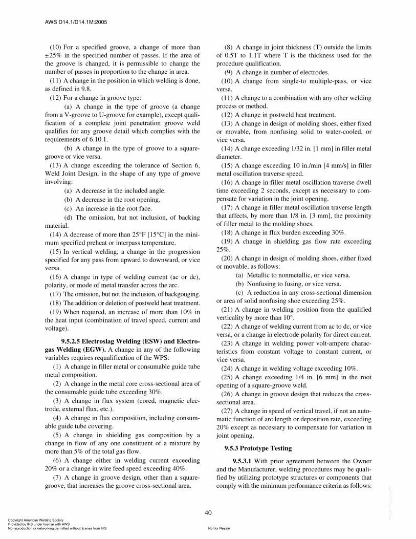
ßÉÍ ÜïìòïñÜïìòïÓæîððë
40
(10) For a specified groove, a change of more than±25% in the specified number of passes. If the area ofthe groove is changed, it is permissible to change thenumber of passes in proportion to the change in area.
(11) A change in the position in which welding is done,as defined in 9.8.
(12) For a change in groove type:(a) A change in the type of groove (a change
from a V-groove to U-groove for example), except quali-fication of a complete joint penetration groove weldqualifies for any groove detail which complies with therequirements of 6.10.1.
(b) A change in the type of groove to a square-groove or vice versa.
(13) A change exceeding the tolerance of Section 6,Weld Joint Design, in the shape of any type of grooveinvolving:
(a) A decrease in the included angle.(b) A decrease in the root opening.(c) An increase in the root face.(d) The omission, but not inclusion, of backing
material.(14) A decrease of more than 25°F [15°C] in the mini-
mum specified preheat or interpass temperature.(15) In vertical welding, a change in the progression
specified for any pass from upward to downward, or viceversa.
(16) A change in type of welding current (ac or dc),polarity, or mode of metal transfer across the arc.
(17) The omission, but not the inclusion, of backgouging.(18) The addition or deletion of postweld heat treatment.(19) When required, an increase of more than 10% in
the heat input (combination of travel speed, current andvoltage).
9.5.2.5 Electroslag Welding (ESW) and Electro-gas Welding (EGW). A change in any of the followingvariables requires requalification of the WPS:
(1) A change in filler metal or consumable guide tubemetal composition.
(2) A change in the metal core cross-sectional area ofthe consumable guide tube exceeding 30%.
(3) A change in flux system (cored, magnetic elec-trode, external flux, etc.).
(4) A change in flux composition, including consum-able guide tube covering.
(5) A change in shielding gas composition by achange in flow of any one constituent of a mixture bymore than 5% of the total gas flow.
(6) A change either in welding current exceeding20% or a change in wire feed speed exceeding 40%.
(7) A change in groove design, other than a square-groove, that increases the groove cross-sectional area.
(8) A change in joint thickness (T) outside the limitsof 0.5T to 1.1T where T is the thickness used for theprocedure qualification.
(9) A change in number of electrodes.(10) A change from single-to multiple-pass, or vice
versa.(11) A change to a combination with any other welding
process or method.(12) A change in postweld heat treatment.(13) A change in design of molding shoes, either fixed
or movable, from nonfusing solid to water-cooled, orvice versa.
(14) A change exceeding 1/32 in. [1 mm] in filler metaldiameter.
(15) A change exceeding 10 in./min [4 mm/s] in fillermetal oscillation traverse speed.
(16) A change in filler metal oscillation traverse dwelltime exceeding 2 seconds, except as necessary to com-pensate for variation in the joint opening.
(17) A change in filler metal oscillation traverse lengththat affects, by more than 1/8 in. [3 mm], the proximityof filler metal to the molding shoes.
(18) A change in flux burden exceeding 30%.(19) A change in shielding gas flow rate exceeding
25%.(20) A change in design of molding shoes, either fixed
or movable, as follows:(a) Metallic to nonmetallic, or vice versa.(b) Nonfusing to fusing, or vice versa.(c) A reduction in any cross-sectional dimension
or area of solid nonfusing shoe exceeding 25%.(21) A change in welding position from the qualified
verticality by more than 10°.(22) A change of welding current from ac to dc, or vice
versa, or a change in electrode polarity for direct current.(23) A change in welding power volt-ampere charac-
teristics from constant voltage to constant current, orvice versa.
(24) A change in welding voltage exceeding 10%.(25) A change exceeding 1/4 in. [6 mm] in the root
opening of a square-groove weld.(26) A change in groove design that reduces the cross-
sectional area.(27) A change in speed of vertical travel, if not an auto-
matic function of arc length or deposition rate, exceeding20% except as necessary to compensate for variation injoint opening.
9.5.3 Prototype Testing
9.5.3.1 With prior agreement between the Ownerand the Manufacturer, welding procedures may be quali-fied by utilizing prototype structures or components thatcomply with the minimum performance criteria as follows:
ݱ°§®·¹¸¬ ß³»®·½¿² É»´¼·²¹ ͱ½·»¬§ Ю±ª·¼»¼ ¾§ ×ØÍ «²¼»® ´·½»²» ©·¬¸ ßÉÍ
Ò±¬ º±® λ¿´»Ò± ®»°®±¼«½¬·±² ±® ²»¬©±®µ·²¹ °»®³·¬¬»¼ ©·¬¸±«¬ ´·½»²» º®±³ ×ØÍ
óóÀôôÀôôÀóÀóÀôôÀôôÀôÀôôÀóóó

ßÉÍ ÜïìòïñÜïìòïÓæîððë
41
(1) Simulated service tests of a welded assembly or amockup of the welded joint. The simulated service testshall include impact loading, loading in bending, staticloading, or fatigue testing to duplicate the type of loadingthe joint will be subjected to in service.
(2) A field test of the welded assembly on a machineloaded and performing the work for which it wasdesigned.
9.5.3.2 For simulated service or field tests, thefollowing shall be documented and recorded:
(1) The weldment drawing to which the test part orassembly was made.
(2) The material specifications of all items includedin the assembly.
(3) The detailed welding procedure employed includ-ing welding process, filler metal, joint preparation, pre-heat, welding conditions, and sequence of weld passes(see Annex A).
(4) The type of loading applied, direction, and mag-nitude of forces (by calculation or instrumentation), fre-quency and total number of applications, or specificduration of the test.
(5) The results of visual examination and nondestruc-tive testing of all welded joints subjected to loading inthe test.
(6) The results of destructive tests of weldments.
9.5.3.3 The welding procedure employed for thetest assembly shall be considered qualified provided thefollowing are met:
(1) Visual and any required nondestructive examina-tions, prior to test, meet the requirements of Section 10,Weld Quality and Inspection.
(2) Specified examinations conducted after test as-sure performance criteria are met.
9.5.3.4 A test assembly welding procedure shall berequalified when a change in an essential variableexceeds the limits for the welding process (see 9.5.2.1through 9.5.2.5).
9.6 Types of Tests and Purposes. The tests that are usedto determine the mechanical properties and soundness ofwelded joints made to qualify a welding procedure are asfollows:
9.6.1 Groove Welds. The tests for groove welds areas follows:
(1) Reduced-section tension test for tensile strength,(2) Root-, face-, and side-bend tests for soundness,(3) Radiographic test for soundness,(4) Ultrasonic test for soundness,(5) All-weld-metal tension test for mechanical
properties,(6) Impact test for toughness, and
(7) Macroetch test for soundness and weld size inpartial joint penetration groove welds.
9.6.2 Fillet Welds. Fillet welds should be macroetchtested for soundness and fusion.
9.7 Base Metal. The base metal and the preparation forwelding shall be that specified in the procedure specifi-cation being qualified. For all types of welded joints, thelength of the welded joint and dimensions of the basemetal shall provide sufficient material for the requiredtest specimens.
9.8 Position of Test Welds
9.8.1 All welds that will be encountered in actual con-struction shall be classified as flat, horizontal, vertical, oroverhead. Welding position limitations for procedurequalification are shown in Table 13.
9.8.2 Plate Groove Weld Tests. When making teststo qualify welding procedures for groove welds in plate,test plates shall be welded in each of the positions to bequalified as follows:
(1) Position 1G (flat)�The test plates shall be placedin an approximately horizontal plane and the weld metaldeposited on the upper side. See Figure 11(A).
(2) Position 2G (horizontal)�The test plates shall beplaced in an approximately vertical plane with thegroove approximately horizontal. See Figure 11(B).
(3) Position 3G (vertical)�The test plates shall beplaced in an approximately vertical plane with thegroove approximately vertical. See Figure 11(C).
(4) Position 4G (overhead)�The test plates shall beplaced in an approximately horizontal plane, and theweld metal deposited on the under side. See Figure11(D).
9.8.3 Pipe Groove Weld Tests. When making tests toqualify welding procedures for groove welds in pipe, testpipes shall be welded in each of the positions to be quali-fied as follows:
(1) Position 1G (pipe horizontal, rolled)�The testpipe shall be placed with its axis horizontal and thegroove approximately vertical. The pipe shall be rotatedduring welding so the weld metal is deposited on theupper side. See Figure 12(A).
(2) Position 2G (pipe vertical)�The test pipe shallbe placed with its axis vertical to the welding grooveapproximately horizontal. The pipe shall not be rotatedduring welding. See Figure 12(B).
(3) Position 5G (pipe horizontal, fixed)�The testpipe shall be placed with its axis horizontal and thegroove approximately vertical. The pipe is not rotatedduring welding. See Figure 12(C).
ݱ°§®·¹¸¬ ß³»®·½¿² É»´¼·²¹ ͱ½·»¬§ Ю±ª·¼»¼ ¾§ ×ØÍ «²¼»® ´·½»²» ©·¬¸ ßÉÍ
Ò±¬ º±® λ¿´»Ò± ®»°®±¼«½¬·±² ±® ²»¬©±®µ·²¹ °»®³·¬¬»¼ ©·¬¸±«¬ ´·½»²» º®±³ ×ØÍ
óóÀôôÀôôÀóÀóÀôôÀôôÀôÀôôÀóóó
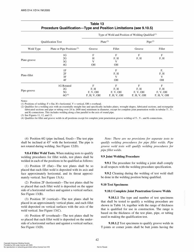
ßÉÍ ÜïìòïñÜïìòïÓæîððë
42
(4) Position 6G (pipe inclined, fixed)�The test pipeshall be inclined at 45° with the horizontal. The pipe isnot rotated during welding. See Figure 12(D).
9.8.4 Fillet Weld Tests. When making tests to qualifywelding procedures for fillet welds, test plates shall bewelded in each of the positions to be qualified as follows:
(1) Position 1F (flat)�The test plates shall be soplaced that each fillet weld is deposited with its axis andface approximately horizontal, and its throat approxi-mately vertical. See Figure 13(A).
(2) Position 2F (horizontal)�The test plates shall beso placed that each fillet weld is deposited on the upperside of a horizontal surface and against a vertical surface.See Figure 13(B).
(3) Position 3F (vertical)�The test plates shall beplaced in an approximately vertical plane, and each filletweld deposited on vertical surfaces with the axis of theweld vertical. See Figure 13(C).
(4) Position 4F (overhead)�The test plates shall beso placed that each fillet weld is deposited on the under-side of a horizontal surface and against a vertical surface.See Figure 13(D).
Note: There are no provisions for separate tests toqualify welding procedures for pipe fillet welds. Pipegroove weld tests will qualify welding procedures forpipe fillet welds.
9.9 Joint Welding Procedure
9.9.1 The procedure for welding a joint shall complyin all respects with the welding procedure specification.
9.9.2 Cleaning during the welding of test weld shallbe done in the welding position being qualified.
9.10 Test Specimens
9.10.1 Complete Joint Penetration Groove Welds
9.10.1.1 The type and number of test specimensthat shall be tested to qualify a welding procedure areshown in Table 14, together with the range of thicknessthat is qualified for use in construction. The range isbased on the thickness of the test plate, pipe, or tubingused in making the qualification test.
9.10.1.2 Test specimens to qualify groove welds inT-joints or corner joints shall be butt joints having the
Ì¿¾´» ïíЮ±½»¼«®» Ï«¿´·º·½¿¬·±²�̧°» ¿²¼ б·¬·±² Ô·³·¬¿¬·±² ø»» çòïðòë÷
Qualification Test
Type of Weld and Position of Welding Qualified(1)
Plate(2) Pipe(2)
Weld Type Plate or Pipe Positions(3) Groove Fillet Groove Fillet
Plate-groove
1G2G3G4G
FHV
OH
FF, H
VOH
FF, H
FF, H
Plate-fillet
1F2F3F4F
FF, H
VOH
F,F, H
VOH
Pipe-groove
1G Rotated2G5G
(4)6G(4)
FF, H
F, V, OHF, H, V, OH
FF, H
F, V, OHF, H, V, OH
FF, H
F, V, OHF, H, V, OH
FF, H
F, V, OHF, H, V, OH
Notes:(1) Positions of welding: F = flat, H = horizontal, V = vertical, OH = overhead.(2) Qualifies for a welding axis with an essentially straight line and specifically includes plates, wrought shapes, fabricated sections, and rectangular
fabricated sections and pipe or tubing over 24 in. [600 mm] minimum in diameter, except for complete joint penetration welds in tubular T-, Y-,and K-connections. This includes welding along a line parallel to the axis of round pipe.
(3) See Figures 11, 12, and 13.(4) Qualifies for fillet and groove welds in all positions except for complete joint penetration groove welding of T-, Y-, and K-connections.
ݱ°§®·¹¸¬ ß³»®·½¿² É»´¼·²¹ ͱ½·»¬§ Ю±ª·¼»¼ ¾§ ×ØÍ «²¼»® ´·½»²» ©·¬¸ ßÉÍ
Ò±¬ º±® λ¿´»Ò± ®»°®±¼«½¬·±² ±® ²»¬©±®µ·²¹ °»®³·¬¬»¼ ©·¬¸±«¬ ´·½»²» º®±³ ×ØÍ
óóÀôôÀôôÀóÀóÀôôÀôôÀôÀôôÀóóó
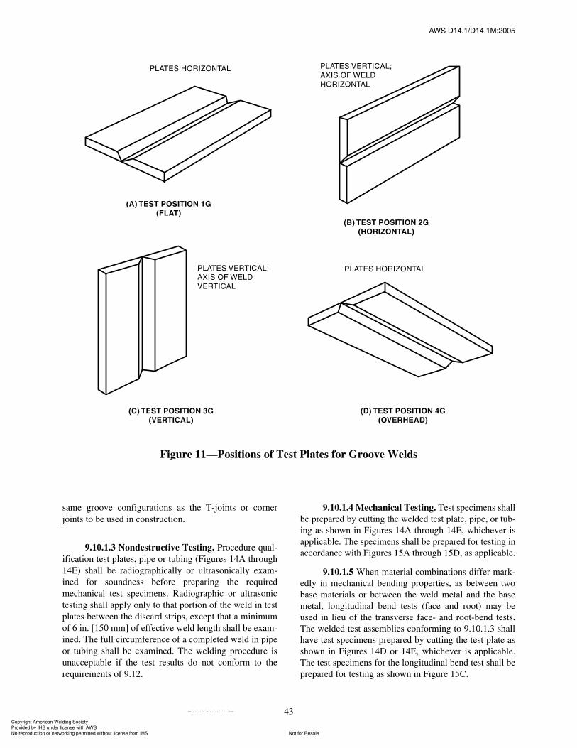
ßÉÍ ÜïìòïñÜïìòïÓæîððë
43
same groove configurations as the T-joints or cornerjoints to be used in construction.
9.10.1.3 Nondestructive Testing. Procedure qual-ification test plates, pipe or tubing (Figures 14A through14E) shall be radiographically or ultrasonically exam-ined for soundness before preparing the requiredmechanical test specimens. Radiographic or ultrasonictesting shall apply only to that portion of the weld in testplates between the discard strips, except that a minimumof 6 in. [150 mm] of effective weld length shall be exam-ined. The full circumference of a completed weld in pipeor tubing shall be examined. The welding procedure isunacceptable if the test results do not conform to therequirements of 9.12.
9.10.1.4 Mechanical Testing. Test specimens shallbe prepared by cutting the welded test plate, pipe, or tub-ing as shown in Figures 14A through 14E, whichever isapplicable. The specimens shall be prepared for testing inaccordance with Figures 15A through 15D, as applicable.
9.10.1.5 When material combinations differ mark-edly in mechanical bending properties, as between twobase materials or between the weld metal and the basemetal, longitudinal bend tests (face and root) may beused in lieu of the transverse face- and root-bend tests.The welded test assemblies conforming to 9.10.1.3 shallhave test specimens prepared by cutting the test plate asshown in Figures 14D or 14E, whichever is applicable.The test specimens for the longitudinal bend test shall beprepared for testing as shown in Figure 15C.
Figure 11�Positions of Test Plates for Groove Welds
ݱ°§®·¹¸¬ ß³»®·½¿² É»´¼·²¹ ͱ½·»¬§ Ю±ª·¼»¼ ¾§ ×ØÍ «²¼»® ´·½»²» ©·¬¸ ßÉÍ
Ò±¬ º±® λ¿´»Ò± ®»°®±¼«½¬·±² ±® ²»¬©±®µ·²¹ °»®³·¬¬»¼ ©·¬¸±«¬ ´·½»²» º®±³ ×ØÍ
óóÀôôÀôôÀóÀóÀôôÀôôÀôÀôôÀóóó
ßÉÍ ÜïìòïñÜïìòïÓæîððë
44
Figure 12�Positions of Test Pipe or Tubing for Groove Welds
ݱ°§®·¹¸¬ ß³»®·½¿² É»´¼·²¹ ͱ½·»¬§ Ю±ª·¼»¼ ¾§ ×ØÍ «²¼»® ´·½»²» ©·¬¸ ßÉÍ
Ò±¬ º±® λ¿´»Ò± ®»°®±¼«½¬·±² ±® ²»¬©±®µ·²¹ °»®³·¬¬»¼ ©·¬¸±«¬ ´·½»²» º®±³ ×ØÍ
óóÀôôÀôôÀóÀóÀôôÀôôÀôÀôôÀóóó

ßÉÍ ÜïìòïñÜïìòïÓæîððë
45
9.10.2 Partial Joint Penetration Groove Welds
9.10.2.1 A sample weld shall be made using thetype of groove design and joint welding procedure to beused in construction, except that the depth of grooveneed not exceed 1 in. [25 mm]. If the partial joint pene-tration groove weld is to be used for corner or T-joints,the butt joint shall have a temporary restrictive plate inthe plane of the square face to simulate a T-joint configu-ration. The sample weld shall first be visually examinedto 9.12.7 and, if applicable, further examined as follows:
9.10.2.2 For joint welding procedures which con-form in all respects to Sections 7 (Workmanship) and 8
(Processes and Filler Metals), three macroetch cross sec-tion specimens shall be prepared to demonstrate that thedesignated effective throat (obtained from the require-ments of the procedure specification) is met.
9.10.2.3 When a joint welding procedure has beenqualified for a complete joint penetration groove weldand is applied to the welding conditions of a partial jointpenetration groove weld, three macroetch cross sectiontest specimens are required.
9.10.2.4 If a joint welding procedure is not coveredby either 9.10.2.2 or 9.10.2.3, or if the welding variablesdo not meet a prequalified status or have not been used
Figure 13�Positions of Test Plates for Fillet Welds
ݱ°§®·¹¸¬ ß³»®·½¿² É»´¼·²¹ ͱ½·»¬§ Ю±ª·¼»¼ ¾§ ×ØÍ «²¼»® ´·½»²» ©·¬¸ ßÉÍ
Ò±¬ º±® λ¿´»Ò± ®»°®±¼«½¬·±² ±® ²»¬©±®µ·²¹ °»®³·¬¬»¼ ©·¬¸±«¬ ´·½»²» º®±³ ×ØÍ
óóÀôôÀôôÀóÀóÀôôÀôôÀôÀôôÀóóó
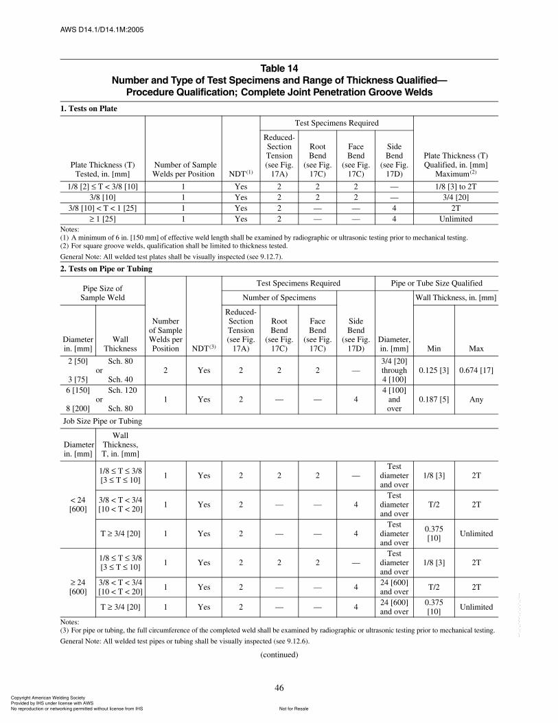
ßÉÍ ÜïìòïñÜïìòïÓæîððë
46
Ì¿¾´» ïìÒ«³¾»® ¿²¼ ̧°» ±º Ì»¬ Í°»½·³»² ¿²¼ ο²¹» ±º ̸·½µ²» Ï«¿´·º·»¼�
Ю±½»¼«®» Ï«¿´·º·½¿¬·±²å ݱ³°´»¬» Ö±·²¬ л²»¬®¿¬·±² Ù®±±ª» É»´¼
1. Tests on Plate
Plate Thickness (T) Tested, in. [mm]
Number of Sample Welds per Position NDT(1)
Test Specimens Required
Plate Thickness (T)Qualified, in. [mm]
Maximum(2)
Reduced- Section Tension (see Fig.
17A)
RootBend
(see Fig. 17C)
FaceBend
(see Fig. 17C)
SideBend
(see Fig. 17D)
1/8 [2] T < 3/8 [10] 1 Yes 2 2 2 � 1/8 [3] to 2T3/8 [10] 1 Yes 2 2 2 � 3/4 [20]
3/8 [10] < T < 1 [25] 1 Yes 2 � � 4 2T1 [25] 1 Yes 2 � � 4 Unlimited
Notes:(1) A minimum of 6 in. [150 mm] of effective weld length shall be examined by radiographic or ultrasonic testing prior to mechanical testing.(2) For square groove welds, qualification shall be limited to thickness tested.
General Note: All welded test plates shall be visually inspected (see 9.12.7).
2. Tests on Pipe or Tubing
Pipe Size ofSample Weld
Numberof Sample Welds per Position NDT(3)
Test Specimens Required Pipe or Tube Size Qualified
Number of Specimens
SideBend
(see Fig. 17D)
Diameter, in. [mm]
Wall Thickness, in. [mm]
Diameterin. [mm]
WallThickness
Reduced- Section Tension (see Fig.
17A)
RootBend
(see Fig. 17C)
FaceBend
(see Fig. 17C) Min Max
2 [50]
3 [75]
Sch. 80or
Sch. 402 Yes 2 2 2 �
3/4 [20]through4 [100]
0.125 [3] 0.674 [17]
6 [150]
8 [200]
Sch. 120or
Sch. 801 Yes 2 � � 4
4 [100]andover
0.187 [5] Any
Job Size Pipe or Tubing
Diameterin. [mm]
WallThickness,T, in. [mm]
1/8 T 3/8[3 T 10] 1 Yes 2 2 2 �
Testdiameter and over
1/8 [3] 2T
< 24[600]
3/8 < T < 3/4[10 < T < 20] 1 Yes 2 � � 4
Testdiameter and over
T/2 2T
T 3/4 [20] 1 Yes 2 � � 4Test
diameter and over
0.375[10] Unlimited
1/8 T 3/8[3 T 10] 1 Yes 2 2 2 �
Testdiameter and over
1/8 [3] 2T
24[600]
3/8 < T < 3/4[10 < T < 20] 1 Yes 2 � � 4 24 [600]
and over T/2 2T
T 3/4 [20] 1 Yes 2 � � 4 24 [600]and over
0.375[10] Unlimited
Notes:(3) For pipe or tubing, the full circumference of the completed weld shall be examined by radiographic or ultrasonic testing prior to mechanical testing.
General Note: All welded test pipes or tubing shall be visually inspected (see 9.12.6).
(continued)
ݱ°§®·¹¸¬ ß³»®·½¿² É»´¼·²¹ ͱ½·»¬§ Ю±ª·¼»¼ ¾§ ×ØÍ «²¼»® ´·½»²» ©·¬¸ ßÉÍ
Ò±¬ º±® λ¿´»Ò± ®»°®±¼«½¬·±² ±® ²»¬©±®µ·²¹ °»®³·¬¬»¼ ©·¬¸±«¬ ´·½»²» º®±³ ×ØÍ
óóÀôôÀôôÀóÀóÀôôÀôôÀôÀôôÀóóó
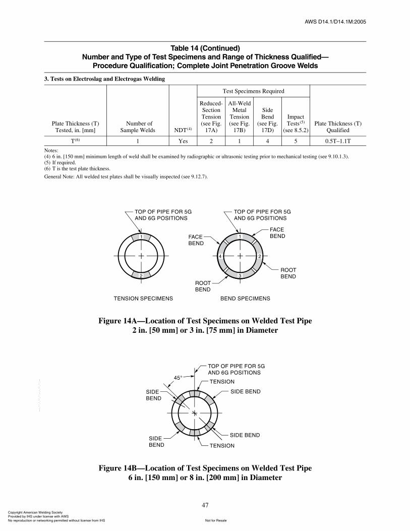
ßÉÍ ÜïìòïñÜïìòïÓæîððë
47
Figure 14A�Location of Test Specimens on Welded Test Pipe2 in. [50 mm] or 3 in. [75 mm] in Diameter
Figure 14B�Location of Test Specimens on Welded Test Pipe6 in. [150 mm] or 8 in. [200 mm] in Diameter
Ì¿¾´» ïì øݱ²¬·²«»¼÷Ò«³¾»® ¿²¼ ̧°» ±º Ì»¬ Í°»½·³»² ¿²¼ ο²¹» ±º ̸·½µ²» Ï«¿´·º·»¼�
Ю±½»¼«®» Ï«¿´·º·½¿¬·±²å ݱ³°´»¬» Ö±·²¬ л²»¬®¿¬·±² Ù®±±ª» É»´¼
3. Tests on Electroslag and Electrogas Welding
Plate Thickness (T) Tested, in. [mm]
Number ofSample Welds NDT(4)
Test Specimens Required
Plate Thickness (T) Qualified
Reduced- Section Tension (see Fig.
17A)
All-Weld Metal
Tension(see Fig.
17B)
SideBend
(see Fig. 17D)
Impact Tests(5)
(see 8.5.2)
T(6) 1 Yes 2 1 4 5 0.5T�1.1T
Notes:(4) 6 in. [150 mm] minimum length of weld shall be examined by radiographic or ultrasonic testing prior to mechanical testing (see 9.10.1.3).(5) If required.(6) T is the test plate thickness.
General Note: All welded test plates shall be visually inspected (see 9.12.7).
ݱ°§®·¹¸¬ ß³»®·½¿² É»´¼·²¹ ͱ½·»¬§ Ю±ª·¼»¼ ¾§ ×ØÍ «²¼»® ´·½»²» ©·¬¸ ßÉÍ
Ò±¬ º±® λ¿´»Ò± ®»°®±¼«½¬·±² ±® ²»¬©±®µ·²¹ °»®³·¬¬»¼ ©·¬¸±«¬ ´·½»²» º®±³ ×ØÍ
óóÀôôÀôôÀóÀóÀôôÀôôÀôÀôôÀóóó
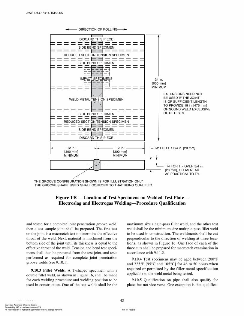
ßÉÍ ÜïìòïñÜïìòïÓæîððë
48
and tested for a complete joint penetration groove weld,then a test sample joint shall be prepared. The first teston the joint is a macroetch test to determine the effectivethroat of the weld. Next, material is machined from thebottom side of the joint until its thickness is equal to theeffective throat of the weld. Tension and bend test speci-mens shall then be prepared from the test joint, and testsperformed as required for complete joint penetrationgroove welds (see 9.10.1).
9.10.3 Fillet Welds. A T-shaped specimen with adouble fillet weld, as shown in Figure 16, shall be madefor each welding procedure and welding position to beused in construction. One of the test welds shall be the
maximum size single-pass fillet weld, and the other testweld shall be the minimum size multiple-pass fillet weldto be used in construction. The weldments shall be cutperpendicular to the direction of welding at three loca-tions, as shown in Figure 16. One face of each of thethree cuts shall be prepared for macroetch examination inaccordance with 9.11.2.
9.10.4 Test specimens may be aged between 200°Fand 225°F [95°C and 105°C] for 46 to 50 hours whenrequired or permitted by the filler metal specificationapplicable to the weld metal being tested.
9.10.5 Qualification on pipe shall also qualify forplate, but not vice versa. One exception is that qualifica-
Figure 14C�Location of Test Specimens on Welded Test Plate�Electroslag and Electrogas Welding�Procedure Qualification
ݱ°§®·¹¸¬ ß³»®·½¿² É»´¼·²¹ ͱ½·»¬§ Ю±ª·¼»¼ ¾§ ×ØÍ «²¼»® ´·½»²» ©·¬¸ ßÉÍ
Ò±¬ º±® λ¿´»Ò± ®»°®±¼«½¬·±² ±® ²»¬©±®µ·²¹ °»®³·¬¬»¼ ©·¬¸±«¬ ´·½»²» º®±³ ×ØÍ
óóÀôôÀôôÀóÀóÀôôÀôôÀôÀôôÀóóó
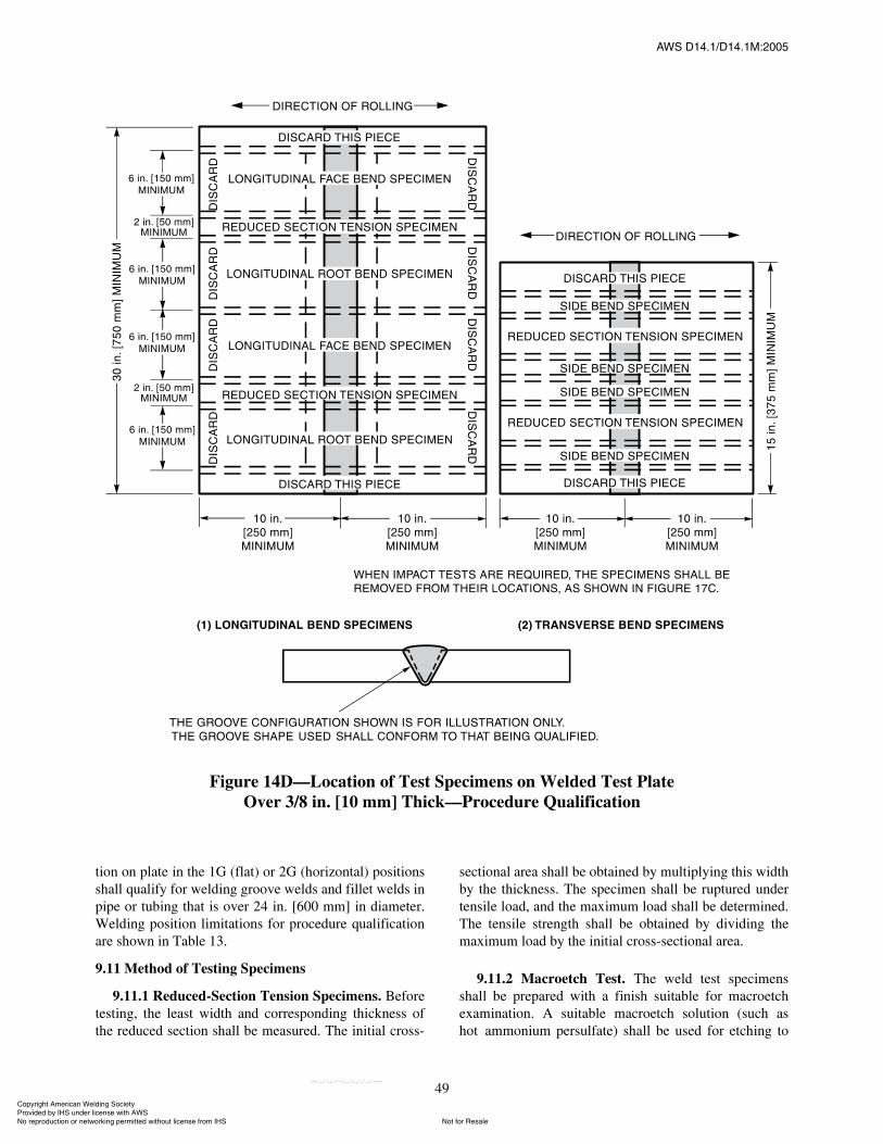
ßÉÍ ÜïìòïñÜïìòïÓæîððë
49
tion on plate in the 1G (flat) or 2G (horizontal) positionsshall qualify for welding groove welds and fillet welds inpipe or tubing that is over 24 in. [600 mm] in diameter.Welding position limitations for procedure qualificationare shown in Table 13.
9.11 Method of Testing Specimens
9.11.1 Reduced-Section Tension Specimens. Beforetesting, the least width and corresponding thickness ofthe reduced section shall be measured. The initial cross-
sectional area shall be obtained by multiplying this widthby the thickness. The specimen shall be ruptured undertensile load, and the maximum load shall be determined.The tensile strength shall be obtained by dividing themaximum load by the initial cross-sectional area.
9.11.2 Macroetch Test. The weld test specimensshall be prepared with a finish suitable for macroetchexamination. A suitable macroetch solution (such ashot ammonium persulfate) shall be used for etching to
Figure 14D�Location of Test Specimens on Welded Test PlateOver 3/8 in. [10 mm] Thick�Procedure Qualification
ݱ°§®·¹¸¬ ß³»®·½¿² É»´¼·²¹ ͱ½·»¬§ Ю±ª·¼»¼ ¾§ ×ØÍ «²¼»® ´·½»²» ©·¬¸ ßÉÍ
Ò±¬ º±® λ¿´»Ò± ®»°®±¼«½¬·±² ±® ²»¬©±®µ·²¹ °»®³·¬¬»¼ ©·¬¸±«¬ ´·½»²» º®±³ ×ØÍ
óóÀôôÀôôÀóÀóÀôôÀôôÀôÀôôÀóóó

ßÉÍ ÜïìòïñÜïìòïÓæîððë
50
accentuate the gross structure of the weld and anyexposed internal discontinuities.
9.11.3 Root-, Face-, and Side-Bend Specimens
9.11.3.1 Each specimen shall be bent in a guidedbend test jig. Any convenient means may be used tocomplete the bend test (see 9.27.1).
9.11.3.2 Face-bend specimens shall be oriented sothat the face of the weld will be in tension. Root-bend
and fillet-weld-soundness specimens shall be oriented sothat the root of the weld will be in tension. Side-bendspecimens shall be oriented so that the side showing thelarger discontinuity, if any, will be in tension.
9.11.3.3 The specimen shall be formed into a U-shape. The weld and heat-affected zones shall becentered and completely within the bent portion of thespecimen after bending.
Figure 14E�Location of Test Specimens on Welded Test Plate3/8 in. [10 mm] Thick and Under�Procedure Qualification
ݱ°§®·¹¸¬ ß³»®·½¿² É»´¼·²¹ ͱ½·»¬§ Ю±ª·¼»¼ ¾§ ×ØÍ «²¼»® ´·½»²» ©·¬¸ ßÉÍ
Ò±¬ º±® λ¿´»Ò± ®»°®±¼«½¬·±² ±® ²»¬©±®µ·²¹ °»®³·¬¬»¼ ©·¬¸±«¬ ´·½»²» º®±³ ×ØÍ
óóÀôôÀôôÀóÀóÀôôÀôôÀôÀôôÀóóó
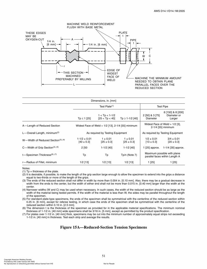
ßÉÍ ÜïìòïñÜïìòïÓæîððë
51
Figure 15A�Reduced-Section Tension Specimens
Ü·³»²·±²ô ·²ò ų³Ã
Ì»¬ д¿¬»øï÷ Ì»¬ з°»
Ì° ï ÅîëÃï ä Ì° ä ïóïñîÅîë ä Ì° ä ìðà ̰ ïóïñî ÅìðÃ
î Åëðà ú í Åéëà ܷ¿³»¬»®
ê Åïëðà ú è Åîððà ܷ¿³»¬»® ±®
Ô¿®¹»®
ß�Ô»²¹¬¸ ±º λ¼«½»¼ Í»½¬·±² É·¼»¬ Ú¿½» ±º É»´¼ õ ïñî ÅïíÃô îóïñì Åëëà ³·²·³«³É·¼»¬ Ú¿½» ±º É»´¼ õ ïñî ÅíÃô
îóïñì Åëëà ³·²·³«³
Ô�Ѫ»®¿´´ Ô»²¹¬¸ô ³·²·³«³øî÷ ß ®»¯«·®»¼ ¾§ Ì»¬·²¹ Û¯«·°³»²¬ ß ®»¯«·®»¼ ¾§ Ì»¬·²¹ Û¯«·°³»²¬
É�É·¼¬¸ ±º λ¼«½»¼ Í»½¬·±²øí÷ô øì÷ ïóïñî o ðòðïÅìð o ðòíÃ
ï o ðòðïÅîë o ðòíÃ
ï o ðòðïÅîë o ðòíÃ
ïñî o ðòðïÅïí o ðòíÃ
íñì o ðòðïÅîð o ðòíÃ
Ý�É·¼¬¸ ±º Ù®·° Í»½¬·±²øì÷ô øë÷ î Åëð ïóïñî Åìðà ïóïñî Åìðà ï Åîëà ¿°°®±¨ò ïóïñì Åíðà ¿°°®±¨ò
¬�Í°»½·³»² ̸·½µ²»øê÷ô øé÷ Ì° Ì° Ì°ñ² øÒ±¬» é÷Ó¿¨·³«³ °±·¾´» ©·¬¸ °´¿²»°¿®¿´´»´ º¿½» ©·¬¸·² Ô»²¹¬¸ ß
®�ο¼·« ±º Ú·´´»¬ô ³·²·³«³ ïñî Åïíà ïñî Åïíà ïñî Åïíà ï Åîëà ï ÅîëÃ
Ò±¬»æøï÷ Ì° ã ¬¸·½µ²» ±º ¬¸» °´¿¬»òøî÷ ׬ · ¼»·®¿¾´»ô ·º °±·¾´»ô ¬± ³¿µ» ¬¸» ´»²¹¬¸ ±º ¬¸» ¹®·° »½¬·±² ´¿®¹» »²±«¹¸ ¬± ¿´´±© ¬¸» °»½·³»² ¬± »¨¬»²¼ ·²¬± ¬¸» ¹®·° ¿ ¼·¬¿²½»
»¯«¿´ ¬± ¬©±ó¬¸·®¼ ±® ³±®» ±º ¬¸» ´»²¹¬¸ ±º ¬¸» ¹®·°òøí÷ ̸» »²¼ ±º ¬¸» ®»¼«½»¼ »½¬·±² ¸¿´´ ²±¬ ¼·ºº»® ·² ©·¼¬¸ ¾§ ³±®» ¬¸¿² ðòððì ·²ò Åðòïð ³³Ãò ß´±ô ¬¸»®» ³¿§ ¾» ¿ ¹®¿¼«¿´ ¼»½®»¿» ·²
©·¼¬¸ º®±³ ¬¸» »²¼ ¬± ¬¸» ½»²¬»®ô ¾«¬ ¬¸» ©·¼¬¸ ±º »·¬¸»® »²¼ ¸¿´´ ²±¬ ¾» ³±®» ¬¸¿² ðòðïë ·²ò Åðòì𠳳à ´¿®¹»® ¬¸¿² ¬¸» ©·¼¬¸ ¿¬ ¬¸»½»²¬»®ò
øì÷ Ò¿®®±©»® ©·¼¬¸ øÉ ¿²¼ Ý÷ ³¿§ ¾» «»¼ ©¸»² ²»½»¿®§ò ײ «½¸ ½¿»ô ¬¸» ©·¼¬¸ ±º ¬¸» ®»¼«½»¼ »½¬·±² ¸±«´¼ ¾» ¿ ´¿®¹» ¿ ¬¸»©·¼¬¸ ±º ¬¸» ³¿¬»®·¿´ ¾»·²¹ ¬»¬»¼ °»®³·¬ò ׺ ¬¸» ©·¼¬¸ ±º ¬¸» ³¿¬»®·¿´ · ´» ¬¸¿² Éô ¬¸» ·¼» ³¿§ ¾» °¿®¿´´»´ ¬¸®±«¹¸±«¬ ¬¸» ´»²¹¬¸±º ¬¸» °»½·³»²ò
øë÷ Ú±® ¬¿²¼¿®¼ °´¿¬»ó¬§°» °»½·³»²ô ¬¸» »²¼ ±º ¬¸» °»½·³»² ¸¿´´ ¾» §³³»¬®·½¿´ ©·¬¸ ¬¸» ½»²¬»®´·²» ±º ¬¸» ®»¼«½»¼ »½¬·±² ©·¬¸·²ðòîë ·²ò Åê ³³Ãô »¨½»°¬ º±® ®»º»®»» ¬»¬·²¹ô ·² ©¸·½¸ ½¿» ¬¸» »²¼ ±º ¬¸» °»½·³»² ¸¿´´ ¾» §³³»¬®·½¿´ ©·¬¸ ¬¸» ½»²¬»®´·²» ±º ¬¸»®»¼«½»¼ »½¬·±² ©·¬¸·² ðòïð ·²ò Åîòë ³³Ãò
øê÷ ̸» ¼·³»²·±² ¬ · ¬¸» ¬¸·½µ²» ±º ¬¸» °»½·³»² ¿ °®±ª·¼»¼ º±® ·² ¬¸» ¿°°´·½¿¾´» ³¿¬»®·¿´ °»½·º·½¿¬·±²ò ̸» ³·²·³«³ ²±³·²¿´¬¸·½µ²» ±º ïóïñî ·²ò Åì𠳳à ©·¼» °»½·³»² ¸¿´´ ¾» íñïê ·²ò Åë ³³Ãô »¨½»°¬ ¿ °»®³·¬¬»¼ ¾§ ¬¸» °®±¼«½¬ °»½·º·½¿¬·±²ò
øé÷ Ú±® °´¿¬» ±ª»® ïóïñî ·²ò Åì𠳳à ¬¸·½µô °»½·³»² ³¿§ ¾» ½«¬ ·²¬± ¬¸» ³·²·³«³ ²«³¾»® ±º ¿°°®±¨·³¿¬»´§ »¯«¿´ ¬®·° ²±¬ »¨½»»¼·²¹ïóïñî ·²ò Åì𠳳à ·² ¬¸·½µ²»ò Ì»¬ »¿½¸ ¬®·° ¿²¼ ¿ª»®¿¹» ¬¸» ®»«´¬ò
ݱ°§®·¹¸¬ ß³»®·½¿² É»´¼·²¹ ͱ½·»¬§ Ю±ª·¼»¼ ¾§ ×ØÍ «²¼»® ´·½»²» ©·¬¸ ßÉÍ
Ò±¬ º±® λ¿´»Ò± ®»°®±¼«½¬·±² ±® ²»¬©±®µ·²¹ °»®³·¬¬»¼ ©·¬¸±«¬ ´·½»²» º®±³ ×ØÍ
óóÀôôÀôôÀóÀóÀôôÀôôÀôÀôôÀóóó
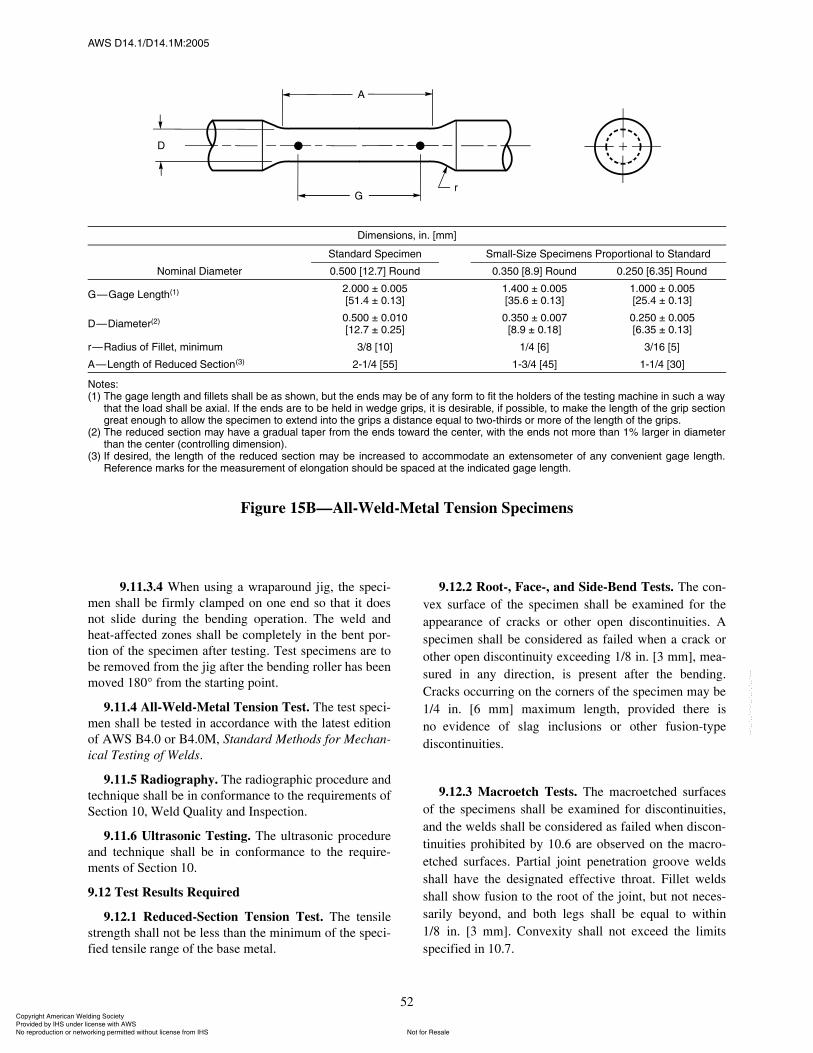
ßÉÍ ÜïìòïñÜïìòïÓæîððë
52
9.11.3.4 When using a wraparound jig, the speci-men shall be firmly clamped on one end so that it doesnot slide during the bending operation. The weld andheat-affected zones shall be completely in the bent por-tion of the specimen after testing. Test specimens are tobe removed from the jig after the bending roller has beenmoved 180° from the starting point.
9.11.4 All-Weld-Metal Tension Test. The test speci-men shall be tested in accordance with the latest editionof AWS B4.0 or B4.0M, Standard Methods for Mechan-ical Testing of Welds.
9.11.5 Radiography. The radiographic procedure andtechnique shall be in conformance to the requirements ofSection 10, Weld Quality and Inspection.
9.11.6 Ultrasonic Testing. The ultrasonic procedureand technique shall be in conformance to the require-ments of Section 10.
9.12 Test Results Required
9.12.1 Reduced-Section Tension Test. The tensilestrength shall not be less than the minimum of the speci-fied tensile range of the base metal.
9.12.2 Root-, Face-, and Side-Bend Tests. The con-vex surface of the specimen shall be examined for theappearance of cracks or other open discontinuities. Aspecimen shall be considered as failed when a crack orother open discontinuity exceeding 1/8 in. [3 mm], mea-sured in any direction, is present after the bending.Cracks occurring on the corners of the specimen may be1/4 in. [6 mm] maximum length, provided there isno evidence of slag inclusions or other fusion-typediscontinuities.
9.12.3 Macroetch Tests. The macroetched surfacesof the specimens shall be examined for discontinuities,and the welds shall be considered as failed when discon-tinuities prohibited by 10.6 are observed on the macro-etched surfaces. Partial joint penetration groove weldsshall have the designated effective throat. Fillet weldsshall show fusion to the root of the joint, but not neces-sarily beyond, and both legs shall be equal to within1/8 in. [3 mm]. Convexity shall not exceed the limitsspecified in 10.7.
Figure 15B�All-Weld-Metal Tension Specimens
Ü·³»²·±²ô ·²ò ų³Ã
Ò±³·²¿´ Ü·¿³»¬»®
ͬ¿²¼¿®¼ Í°»½·³»² ͳ¿´´óÍ·¦» Í°»½·³»² Ю±°±®¬·±²¿´ ¬± ͬ¿²¼¿®¼
ðòëðð Åïîòéà α«²¼ ðòíëð Åèòçà α«²¼ ðòîëð Åêòíëà α«²¼
Ù�Ù¿¹» Ô»²¹¬¸øï÷ îòððð o ðòððëÅëïòì o ðòïíÃ
ïòìðð o ðòððëÅíëòê o ðòïíÃ
ïòððð o ðòððëÅîëòì o ðòïíÃ
Ü�Ü·¿³»¬»®øî÷ ðòëðð o ðòðïðÅïîòé o ðòîëÃ
ðòíëð o ðòððéÅèòç o ðòïèÃ
ðòîëð o ðòððëÅêòíë o ðòïíÃ
®�ο¼·« ±º Ú·´´»¬ô ³·²·³«³ íñè Åïðà ïñì Åêà íñïê ÅëÃ
ß�Ô»²¹¬¸ ±º λ¼«½»¼ Í»½¬·±²øí÷ îóïñì Åëëà ïóíñì Åìëà ïóïñì ÅíðÃ
Ò±¬»æøï÷ ̸» ¹¿¹» ´»²¹¬¸ ¿²¼ º·´´»¬ ¸¿´´ ¾» ¿ ¸±©²ô ¾«¬ ¬¸» »²¼ ³¿§ ¾» ±º ¿²§ º±®³ ¬± º·¬ ¬¸» ¸±´¼»® ±º ¬¸» ¬»¬·²¹ ³¿½¸·²» ·² «½¸ ¿ ©¿§
¬¸¿¬ ¬¸» ´±¿¼ ¸¿´´ ¾» ¿¨·¿´ò ׺ ¬¸» »²¼ ¿®» ¬± ¾» ¸»´¼ ·² ©»¼¹» ¹®·°ô ·¬ · ¼»·®¿¾´»ô ·º °±·¾´»ô ¬± ³¿µ» ¬¸» ´»²¹¬¸ ±º ¬¸» ¹®·° »½¬·±²¹®»¿¬ »²±«¹¸ ¬± ¿´´±© ¬¸» °»½·³»² ¬± »¨¬»²¼ ·²¬± ¬¸» ¹®·° ¿ ¼·¬¿²½» »¯«¿´ ¬± ¬©±ó¬¸·®¼ ±® ³±®» ±º ¬¸» ´»²¹¬¸ ±º ¬¸» ¹®·°ò
øî÷ ̸» ®»¼«½»¼ »½¬·±² ³¿§ ¸¿ª» ¿ ¹®¿¼«¿´ ¬¿°»® º®±³ ¬¸» »²¼ ¬±©¿®¼ ¬¸» ½»²¬»®ô ©·¬¸ ¬¸» »²¼ ²±¬ ³±®» ¬¸¿² ïû ´¿®¹»® ·² ¼·¿³»¬»®¬¸¿² ¬¸» ½»²¬»® ø½±²¬®±´´·²¹ ¼·³»²·±²÷ò
øí÷ ׺ ¼»·®»¼ô ¬¸» ´»²¹¬¸ ±º ¬¸» ®»¼«½»¼ »½¬·±² ³¿§ ¾» ·²½®»¿»¼ ¬± ¿½½±³³±¼¿¬» ¿² »¨¬»²±³»¬»® ±º ¿²§ ½±²ª»²·»²¬ ¹¿¹» ´»²¹¬¸òλº»®»²½» ³¿®µ º±® ¬¸» ³»¿«®»³»²¬ ±º »´±²¹¿¬·±² ¸±«´¼ ¾» °¿½»¼ ¿¬ ¬¸» ·²¼·½¿¬»¼ ¹¿¹» ´»²¹¬¸ò
ݱ°§®·¹¸¬ ß³»®·½¿² É»´¼·²¹ ͱ½·»¬§ Ю±ª·¼»¼ ¾§ ×ØÍ «²¼»® ´·½»²» ©·¬¸ ßÉÍ
Ò±¬ º±® λ¿´»Ò± ®»°®±¼«½¬·±² ±® ²»¬©±®µ·²¹ °»®³·¬¬»¼ ©·¬¸±«¬ ´·½»²» º®±³ ×ØÍ
óóÀôôÀôôÀóÀóÀôôÀôôÀôÀôôÀóóó
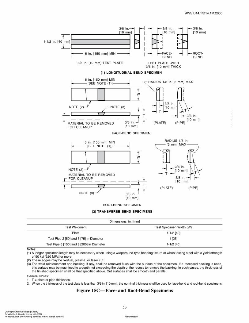
ßÉÍ ÜïìòïñÜïìòïÓæîððë
53
Figure 15C�Face- and Root-Bend Specimens
Ü·³»²·±²ô ·²ò ų³Ã
Ì»¬ É»´¼³»²¬ Ì»¬ Í°»½·³»² É·¼¬¸ øÉ÷
д¿¬» ïóïñî ÅìðÃ
Ì»¬ з°» î Åëðà ¿²¼ í Åéëà ·² Ü·¿³»¬»® ï ÅîëÃ
Ì»¬ з°» ê Åïëðà ¿²¼ è Åîððà ·² Ü·¿³»¬»® ïóïñî ÅìðÃ
Ò±¬»æøï÷ ß ´±²¹»® °»½·³»² ´»²¹¬¸ ³¿§ ¾» ²»½»¿®§ ©¸»² «·²¹ ¿ ©®¿°¿®±«²¼ó¬§°» ¾»²¼·²¹ º·¨¬«®» ±® ©¸»² ¬»¬·²¹ ¬»»´ ©·¬¸ ¿ §·»´¼ ¬®»²¹¬¸
±º çð µ· Åêîð Óпà ±® ³±®»òøî÷ ̸»» »¼¹» ³¿§ ¾» ±¨§º«»´ô °´¿³¿ô ±® ´¿»® ½«¬òøí÷ ̸» ©»´¼ ®»·²º±®½»³»²¬ ¿²¼ ¾¿½µ·²¹ô ·º ¿²§ô ¸¿´´ ¾» ®»³±ª»¼ º´«¸ ©·¬¸ ¬¸» «®º¿½» ±º ¬¸» °»½·³»²ò ׺ ¿ ®»½»»¼ ¾¿½µ·²¹ · «»¼ô
¬¸· «®º¿½» ³¿§ ¾» ³¿½¸·²»¼ ¬± ¿ ¼»°¬¸ ²±¬ »¨½»»¼·²¹ ¬¸» ¼»°¬¸ ±º ¬¸» ®»½» ¬± ®»³±ª» ¬¸» ¾¿½µ·²¹ò ײ «½¸ ½¿»ô ¬¸» ¬¸·½µ²» ±º¬¸» º·²·¸»¼ °»½·³»² ¸¿´´ ¾» ¬¸¿¬ °»½·º·»¼ ¿¾±ª»ò Ý«¬ «®º¿½» ¸¿´´ ¾» ³±±¬¸ ¿²¼ °¿®¿´´»´ò
Ù»²»®¿´ Ò±¬»æïò Ì ã °´¿¬» ±® °·°» ¬¸·½µ²»òîò ɸ»² ¬¸» ¬¸·½µ²» ±º ¬¸» ¬»¬ °´¿¬» · ´» ¬¸¿² íñè ·²ò Åïð ³³Ãô ¬¸» ²±³·²¿´ ¬¸·½µ²» ¸¿´´ ¾» «»¼ º±® º¿½»ó¾»²¼ ¿²¼ ®±±¬ó¾»²¼ °»½·³»²ò
ݱ°§®·¹¸¬ ß³»®·½¿² É»´¼·²¹ ͱ½·»¬§ Ю±ª·¼»¼ ¾§ ×ØÍ «²¼»® ´·½»²» ©·¬¸ ßÉÍ
Ò±¬ º±® λ¿´»Ò± ®»°®±¼«½¬·±² ±® ²»¬©±®µ·²¹ °»®³·¬¬»¼ ©·¬¸±«¬ ´·½»²» º®±³ ×ØÍ
óóÀôôÀôôÀóÀóÀôôÀôôÀôÀôôÀóóó
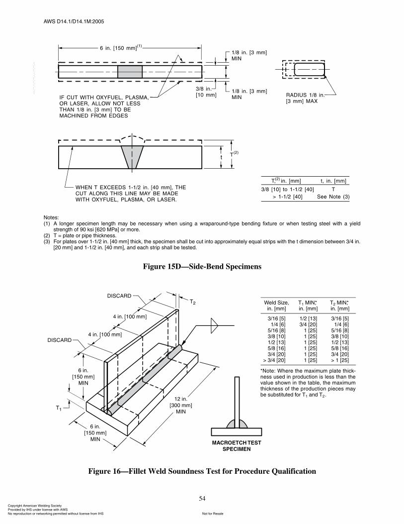
ßÉÍ ÜïìòïñÜïìòïÓæîððë
54
Ò±¬»æøï÷ ß ´±²¹»® °»½·³»² ´»²¹¬¸ ³¿§ ¾» ²»½»¿®§ ©¸»² «·²¹ ¿ ©®¿°¿®±«²¼ó¬§°» ¾»²¼·²¹ º·¨¬«®» ±® ©¸»² ¬»¬·²¹ ¬»»´ ©·¬¸ ¿ §·»´¼
¬®»²¹¬¸ ±º çð µ· Åêîð Óпà ±® ³±®»òøî÷ Ì ã °´¿¬» ±® °·°» ¬¸·½µ²»òøí÷ Ú±® °´¿¬» ±ª»® ïóïñî ·²ò Åì𠳳à ¬¸·½µô ¬¸» °»½·³»² ¸¿´´ ¾» ½«¬ ·²¬± ¿°°®±¨·³¿¬»´§ »¯«¿´ ¬®·° ©·¬¸ ¬¸» ¬ ¼·³»²·±² ¾»¬©»»² íñì ·²ò
Åî𠳳à ¿²¼ ïóïñî ·²ò Åìð ³³Ãô ¿²¼ »¿½¸ ¬®·° ¸¿´´ ¾» ¬»¬»¼ò
Figure 15D�Side-Bend Specimens
Figure 16�Fillet Weld Soundness Test for Procedure Qualification
É»´¼ Í·¦»ô·²ò ų³Ã
Ìï Ó×Òôö·²ò ų³Ã
Ìî Ó×Òôö·²ò ų³Ã
íñïê ÅëÃïñì ÅêÃ
ëñïê ÅèÃíñè ÅïðÃïñî ÅïíÃëñè ÅïêÃíñì ÅîðÃ
â íñì Åîðà â
ïñî ÅïíÃíñì ÅîðÃïñï ÅîëÃïñï ÅîëÃïñï ÅîëÃïñï ÅîëÃïñï ÅîëÃïñï ÅîëÃ
íñïê ÅëÃïñì ÅêÃ
ëñïê ÅèÃíñè ÅïðÃïñî ÅïíÃëñè ÅïêÃíñì ÅîðÃâ ï ÅîëÃ
öÒ±¬»æ ɸ»®» ¬¸» ³¿¨·³«³ °´¿¬» ¬¸·½µó²» «»¼ ·² °®±¼«½¬·±² · ´» ¬¸¿² ¬¸»ª¿´«» ¸±©² ·² ¬¸» ¬¿¾´»ô ¬¸» ³¿¨·³«³¬¸·½µ²» ±º ¬¸» °®±¼«½¬·±² °·»½» ³¿§¾» «¾¬·¬«¬»¼ º±® Ìï ¿²¼ Ìî ò
ݱ°§®·¹¸¬ ß³»®·½¿² É»´¼·²¹ ͱ½·»¬§ Ю±ª·¼»¼ ¾§ ×ØÍ «²¼»® ´·½»²» ©·¬¸ ßÉÍ
Ò±¬ º±® λ¿´»Ò± ®»°®±¼«½¬·±² ±® ²»¬©±®µ·²¹ °»®³·¬¬»¼ ©·¬¸±«¬ ´·½»²» º®±³ ×ØÍ
óóÀôôÀôôÀóÀóÀôôÀôôÀôÀôôÀóóó
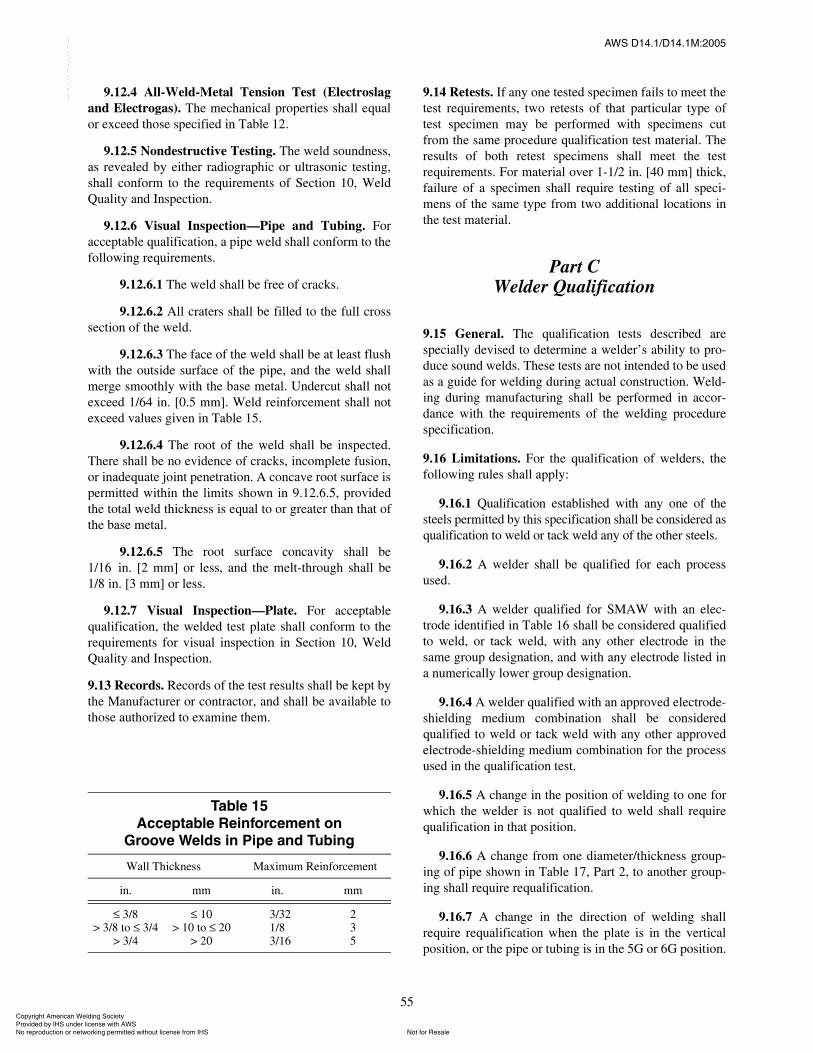
ßÉÍ ÜïìòïñÜïìòïÓæîððë
55
9.12.4 All-Weld-Metal Tension Test (Electroslagand Electrogas). The mechanical properties shall equalor exceed those specified in Table 12.
9.12.5 Nondestructive Testing. The weld soundness,as revealed by either radiographic or ultrasonic testing,shall conform to the requirements of Section 10, WeldQuality and Inspection.
9.12.6 Visual Inspection�Pipe and Tubing. Foracceptable qualification, a pipe weld shall conform to thefollowing requirements.
9.12.6.1 The weld shall be free of cracks.
9.12.6.2 All craters shall be filled to the full crosssection of the weld.
9.12.6.3 The face of the weld shall be at least flushwith the outside surface of the pipe, and the weld shallmerge smoothly with the base metal. Undercut shall notexceed 1/64 in. [0.5 mm]. Weld reinforcement shall notexceed values given in Table 15.
9.12.6.4 The root of the weld shall be inspected.There shall be no evidence of cracks, incomplete fusion,or inadequate joint penetration. A concave root surface ispermitted within the limits shown in 9.12.6.5, providedthe total weld thickness is equal to or greater than that ofthe base metal.
9.12.6.5 The root surface concavity shall be1/16 in. [2 mm] or less, and the melt-through shall be1/8 in. [3 mm] or less.
9.12.7 Visual Inspection�Plate. For acceptablequalification, the welded test plate shall conform to therequirements for visual inspection in Section 10, WeldQuality and Inspection.
9.13 Records. Records of the test results shall be kept bythe Manufacturer or contractor, and shall be available tothose authorized to examine them.
9.14 Retests. If any one tested specimen fails to meet thetest requirements, two retests of that particular type oftest specimen may be performed with specimens cutfrom the same procedure qualification test material. Theresults of both retest specimens shall meet the testrequirements. For material over 1-1/2 in. [40 mm] thick,failure of a specimen shall require testing of all speci-mens of the same type from two additional locations inthe test material.
Part CWelder Qualification
9.15 General. The qualification tests described arespecially devised to determine a welder�s ability to pro-duce sound welds. These tests are not intended to be usedas a guide for welding during actual construction. Weld-ing during manufacturing shall be performed in accor-dance with the requirements of the welding procedurespecification.
9.16 Limitations. For the qualification of welders, thefollowing rules shall apply:
9.16.1 Qualification established with any one of thesteels permitted by this specification shall be considered asqualification to weld or tack weld any of the other steels.
9.16.2 A welder shall be qualified for each processused.
9.16.3 A welder qualified for SMAW with an elec-trode identified in Table 16 shall be considered qualifiedto weld, or tack weld, with any other electrode in thesame group designation, and with any electrode listed ina numerically lower group designation.
9.16.4 A welder qualified with an approved electrode-shielding medium combination shall be consideredqualified to weld or tack weld with any other approvedelectrode-shielding medium combination for the processused in the qualification test.
9.16.5 A change in the position of welding to one forwhich the welder is not qualified to weld shall requirequalification in that position.
9.16.6 A change from one diameter/thickness group-ing of pipe shown in Table 17, Part 2, to another group-ing shall require requalification.
9.16.7 A change in the direction of welding shallrequire requalification when the plate is in the verticalposition, or the pipe or tubing is in the 5G or 6G position.
Ì¿¾´» ïëß½½»°¬¿¾´» λ·²º±®½»³»²¬ ±²
Ù®±±ª» É»´¼ ·² з°» ¿²¼ Ì«¾·²¹
Wall Thickness Maximum Reinforcement
in. mm in. mm
3/8> 3/8 to 3/4
> 3/4> 10 to 20
> 20
3/321/83/16
235
ݱ°§®·¹¸¬ ß³»®·½¿² É»´¼·²¹ ͱ½·»¬§ Ю±ª·¼»¼ ¾§ ×ØÍ «²¼»® ´·½»²» ©·¬¸ ßÉÍ
Ò±¬ º±® λ¿´»Ò± ®»°®±¼«½¬·±² ±® ²»¬©±®µ·²¹ °»®³·¬¬»¼ ©·¬¸±«¬ ´·½»²» º®±³ ×ØÍ
óóÀôôÀôôÀóÀóÀôôÀôôÀôÀôôÀóóó
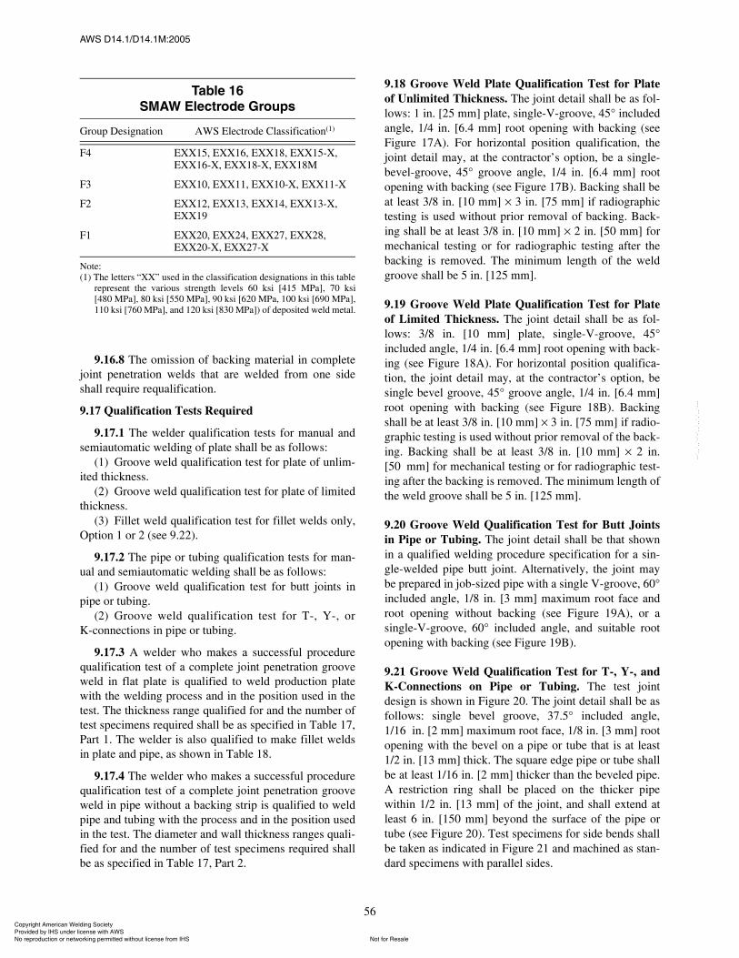
ßÉÍ ÜïìòïñÜïìòïÓæîððë
56
9.16.8 The omission of backing material in completejoint penetration welds that are welded from one sideshall require requalification.
9.17 Qualification Tests Required
9.17.1 The welder qualification tests for manual andsemiautomatic welding of plate shall be as follows:
(1) Groove weld qualification test for plate of unlim-ited thickness.
(2) Groove weld qualification test for plate of limitedthickness.
(3) Fillet weld qualification test for fillet welds only,Option 1 or 2 (see 9.22).
9.17.2 The pipe or tubing qualification tests for man-ual and semiautomatic welding shall be as follows:
(1) Groove weld qualification test for butt joints inpipe or tubing.
(2) Groove weld qualification test for T-, Y-, orK-connections in pipe or tubing.
9.17.3 A welder who makes a successful procedurequalification test of a complete joint penetration grooveweld in flat plate is qualified to weld production platewith the welding process and in the position used in thetest. The thickness range qualified for and the number oftest specimens required shall be as specified in Table 17,Part 1. The welder is also qualified to make fillet weldsin plate and pipe, as shown in Table 18.
9.17.4 The welder who makes a successful procedurequalification test of a complete joint penetration grooveweld in pipe without a backing strip is qualified to weldpipe and tubing with the process and in the position usedin the test. The diameter and wall thickness ranges quali-fied for and the number of test specimens required shallbe as specified in Table 17, Part 2.
9.18 Groove Weld Plate Qualification Test for Plateof Unlimited Thickness. The joint detail shall be as fol-lows: 1 in. [25 mm] plate, single-V-groove, 45° includedangle, 1/4 in. [6.4 mm] root opening with backing (seeFigure 17A). For horizontal position qualification, thejoint detail may, at the contractor�s option, be a single-bevel-groove, 45° groove angle, 1/4 in. [6.4 mm] rootopening with backing (see Figure 17B). Backing shall beat least 3/8 in. [10 mm] I 3 in. [75 mm] if radiographictesting is used without prior removal of backing. Back-ing shall be at least 3/8 in. [10 mm] I 2 in. [50 mm] formechanical testing or for radiographic testing after thebacking is removed. The minimum length of the weldgroove shall be 5 in. [125 mm].
9.19 Groove Weld Plate Qualification Test for Plateof Limited Thickness. The joint detail shall be as fol-lows: 3/8 in. [10 mm] plate, single-V-groove, 45°included angle, 1/4 in. [6.4 mm] root opening with back-ing (see Figure 18A). For horizontal position qualifica-tion, the joint detail may, at the contractor�s option, besingle bevel groove, 45° groove angle, 1/4 in. [6.4 mm]root opening with backing (see Figure 18B). Backingshall be at least 3/8 in. [10 mm] I 3 in. [75 mm] if radio-graphic testing is used without prior removal of the back-ing. Backing shall be at least 3/8 in. [10 mm] I 2 in.[50 mm] for mechanical testing or for radiographic test-ing after the backing is removed. The minimum length ofthe weld groove shall be 5 in. [125 mm].
9.20 Groove Weld Qualification Test for Butt Jointsin Pipe or Tubing. The joint detail shall be that shownin a qualified welding procedure specification for a sin-gle-welded pipe butt joint. Alternatively, the joint maybe prepared in job-sized pipe with a single V-groove, 60°included angle, 1/8 in. [3 mm] maximum root face androot opening without backing (see Figure 19A), or asingle-V-groove, 60° included angle, and suitable rootopening with backing (see Figure 19B).
9.21 Groove Weld Qualification Test for T-, Y-, andK-Connections on Pipe or Tubing. The test jointdesign is shown in Figure 20. The joint detail shall be asfollows: single bevel groove, 37.5° included angle,1/16 in. [2 mm] maximum root face, 1/8 in. [3 mm] rootopening with the bevel on a pipe or tube that is at least1/2 in. [13 mm] thick. The square edge pipe or tube shallbe at least 1/16 in. [2 mm] thicker than the beveled pipe.A restriction ring shall be placed on the thicker pipewithin 1/2 in. [13 mm] of the joint, and shall extend atleast 6 in. [150 mm] beyond the surface of the pipe ortube (see Figure 20). Test specimens for side bends shallbe taken as indicated in Figure 21 and machined as stan-dard specimens with parallel sides.
Ì¿¾´» ïêÍÓßÉ Û´»½¬®±¼» Ù®±«°
Group Designation AWS Electrode Classification(1)
F4 EXX15, EXX16, EXX18, EXX15-X, EXX16-X, EXX18-X, EXX18M
F3 EXX10, EXX11, EXX10-X, EXX11-X
F2 EXX12, EXX13, EXX14, EXX13-X, EXX19
F1 EXX20, EXX24, EXX27, EXX28, EXX20-X, EXX27-X
Note:(1) The letters �XX� used in the classification designations in this table
represent the various strength levels 60 ksi [415 MPa], 70 ksi[480 MPa], 80 ksi [550 MPa], 90 ksi [620 MPa, 100 ksi [690 MPa],110 ksi [760 MPa], and 120 ksi [830 MPa]) of deposited weld metal.
ݱ°§®·¹¸¬ ß³»®·½¿² É»´¼·²¹ ͱ½·»¬§ Ю±ª·¼»¼ ¾§ ×ØÍ «²¼»® ´·½»²» ©·¬¸ ßÉÍ
Ò±¬ º±® λ¿´»Ò± ®»°®±¼«½¬·±² ±® ²»¬©±®µ·²¹ °»®³·¬¬»¼ ©·¬¸±«¬ ´·½»²» º®±³ ×ØÍ
óóÀôôÀôôÀóÀóÀôôÀôôÀôÀôôÀóóó
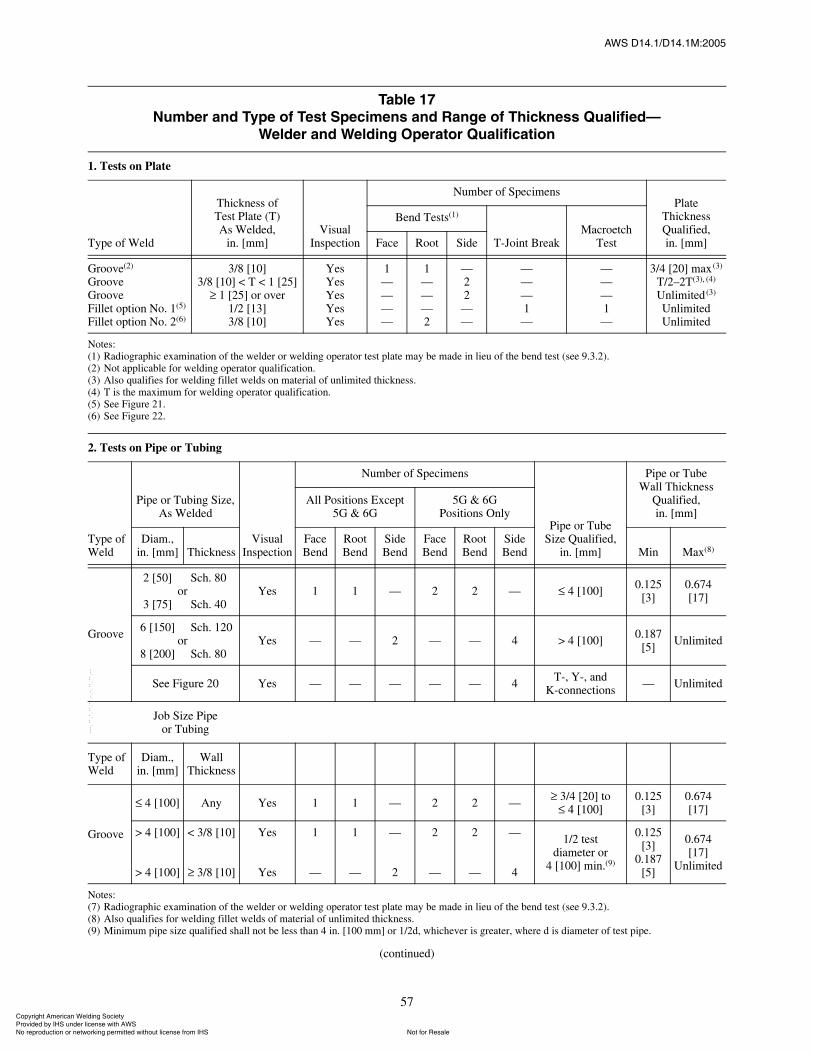
ßÉÍ ÜïìòïñÜïìòïÓæîððë
57
Ì¿¾´» ïéÒ«³¾»® ¿²¼ ̧°» ±º Ì»¬ Í°»½·³»² ¿²¼ ο²¹» ±º ̸·½µ²» Ï«¿´·º·»¼�
É»´¼»® ¿²¼ É»´¼·²¹ Ñ°»®¿¬±® Ï«¿´·º·½¿¬·±²
1. Tests on Plate
Type of Weld
Thickness ofTest Plate (T)As Welded,
in. [mm]Visual
Inspection
Number of SpecimensPlate
Thickness Qualified,in. [mm]
Bend Tests(1)
T-Joint BreakMacroetch
TestFace Root Side
Groove(2)
GrooveGrooveFillet option No. 1(5)
Fillet option No. 2(6)
3/8 [10]3/8 [10] < T < 1 [25]
1 [25] or over1/2 [13]3/8 [10]
YesYesYesYesYes
1����
1���2
�22��
���1�
���1�
3/4 [20] max (3)
T/2�2T(3), (4)
Unlimited (3)
UnlimitedUnlimited
Notes:(1) Radiographic examination of the welder or welding operator test plate may be made in lieu of the bend test (see 9.3.2).(2) Not applicable for welding operator qualification.(3) Also qualifies for welding fillet welds on material of unlimited thickness.(4) T is the maximum for welding operator qualification.(5) See Figure 21.(6) See Figure 22.
2. Tests on Pipe or Tubing
Type of Weld
Pipe or Tubing Size, As Welded
Visual Inspection
Number of Specimens
Pipe or TubeSize Qualified,
in. [mm]
Pipe or TubeWall Thickness
Qualified,in. [mm]
All Positions Except5G & 6G
5G & 6GPositions Only
Diam.,in. [mm] Thickness
Face Bend
Root Bend
Side Bend
Face Bend
Root Bend
Side Bend Min Max(8)
Groove
2 [50]o
3 [75]
Sch. 800r
Sch. 400Yes 1 1 � 2 2 � 4 [100] 0.125
[3]0.674[17]
6 [150]o
8 [200]
Sch. 120r
Sch. 800Yes � � 2 � � 4 > 4 [100] 0.187
[5] Unlimited
See Figure 20 Yes � � � � � 4 T-, Y-, andK-connections � Unlimited
Job Size Pipe or Tubing
Type of Weld
Diam.,in. [mm]
Wall Thickness
Groove
4 [100] Any Yes 1 1 � 2 2 � 3/4 [20] to 0.125[3]
0.674[17]
> 4 [100]
> 4 [100]
< 3/8 [10]
3/8 [10]
Yes
Yes
1
�
1
�
�
2
2
�
2
�
�
4
1/2 testdiameter or
4 [100] min.(9)
0.125[3]
0.187[5]
0.674[17]
Unlimited
Notes:(7) Radiographic examination of the welder or welding operator test plate may be made in lieu of the bend test (see 9.3.2).(8) Also qualifies for welding fillet welds of material of unlimited thickness.(9) Minimum pipe size qualified shall not be less than 4 in. [100 mm] or 1/2d, whichever is greater, where d is diameter of test pipe.
(continued)
ݱ°§®·¹¸¬ ß³»®·½¿² É»´¼·²¹ ͱ½·»¬§ Ю±ª·¼»¼ ¾§ ×ØÍ «²¼»® ´·½»²» ©·¬¸ ßÉÍ
Ò±¬ º±® λ¿´»Ò± ®»°®±¼«½¬·±² ±® ²»¬©±®µ·²¹ °»®³·¬¬»¼ ©·¬¸±«¬ ´·½»²» º®±³ ×ØÍ
óóÀôôÀôôÀóÀóÀôôÀôôÀôÀôôÀóóó
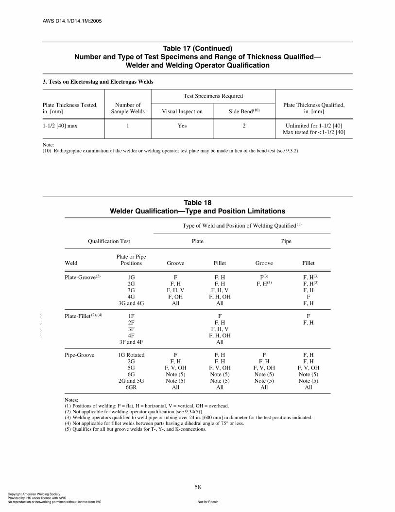
ßÉÍ ÜïìòïñÜïìòïÓæîððë
58
Ì¿¾´» ïé øݱ²¬·²«»¼÷Ò«³¾»® ¿²¼ ̧°» ±º Ì»¬ Í°»½·³»² ¿²¼ ο²¹» ±º ̸·½µ²» Ï«¿´·º·»¼�
É»´¼»® ¿²¼ É»´¼·²¹ Ñ°»®¿¬±® Ï«¿´·º·½¿¬·±²
3. Tests on Electroslag and Electrogas Welds
Plate Thickness Tested,in. [mm]
Number ofSample Welds
Test Specimens Required
Plate Thickness Qualified,in. [mm]Visual Inspection Side Bend(10)
1-1/2 [40] max 1 Yes 2 Unlimited for 1-1/2 [40]Max tested for <1-1/2 [40]
Note:(10) Radiographic examination of the welder or welding operator test plate may be made in lieu of the bend test (see 9.3.2).
Ì¿¾´» ïèÉ»´¼»® Ï«¿´·º·½¿¬·±²�̧°» ¿²¼ б·¬·±² Ô·³·¬¿¬·±²
Qualification Test
Type of Weld and Position of Welding Qualified (1)
Plate Pipe
WeldPlate or Pipe
Positions Groove Fillet Groove Fillet
Plate-Groove(2) 1G2G3G4G
3G and 4G
FF, H
F, H, VF, OH
All
F, HF, H
F, H, VF, H, OH
All
F(3)
F, H(3)
(3)F, H(3)
(3)F, H(3)
F, HF
F, H
Plate-Fillet (2), (4) 1F2F3F4F
3F and 4F
FF, H
F, H, VF, H, OH
All
FF, H
Pipe-Groove 1G Rotated2G5G6G
2G and 5G6GR
FF, H
F, V, OHNote (5)Note (5)
All
F, HF, H
F, V, OHNote (5)Note (5)
All
FF, H
F, V, OHNote (5)Note (5)
All
F, HF, H
F, V, OHNote (5)Note (5)
All
Notes:(1) Positions of welding: F = flat, H = horizontal, V = vertical, OH = overhead.(2) Not applicable for welding operator qualification [see 9.34(5)].(3) Welding operators qualified to weld pipe or tubing over 24 in. [600 mm] in diameter for the test positions indicated.(4) Not applicable for fillet welds between parts having a dihedral angle of 75° or less.(5) Qualifies for all but groove welds for T-, Y-, and K-connections.
ݱ°§®·¹¸¬ ß³»®·½¿² É»´¼·²¹ ͱ½·»¬§ Ю±ª·¼»¼ ¾§ ×ØÍ «²¼»® ´·½»²» ©·¬¸ ßÉÍ
Ò±¬ º±® λ¿´»Ò± ®»°®±¼«½¬·±² ±® ²»¬©±®µ·²¹ °»®³·¬¬»¼ ©·¬¸±«¬ ´·½»²» º®±³ ×ØÍ
óóÀôôÀôôÀóÀóÀôôÀôôÀôÀôôÀóóó
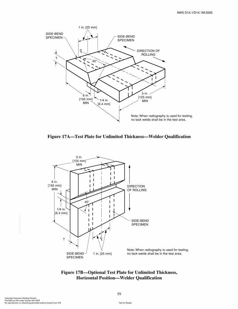
ßÉÍ ÜïìòïñÜïìòïÓæîððë
59
Figure 17A�Test Plate for Unlimited Thickness�Welder Qualification
Figure 17B�Optional Test Plate for Unlimited Thickness,Horizontal Position�Welder Qualification
ݱ°§®·¹¸¬ ß³»®·½¿² É»´¼·²¹ ͱ½·»¬§ Ю±ª·¼»¼ ¾§ ×ØÍ «²¼»® ´·½»²» ©·¬¸ ßÉÍ
Ò±¬ º±® λ¿´»Ò± ®»°®±¼«½¬·±² ±® ²»¬©±®µ·²¹ °»®³·¬¬»¼ ©·¬¸±«¬ ´·½»²» º®±³ ×ØÍ
óóÀôôÀôôÀóÀóÀôôÀôôÀôÀôôÀóóó
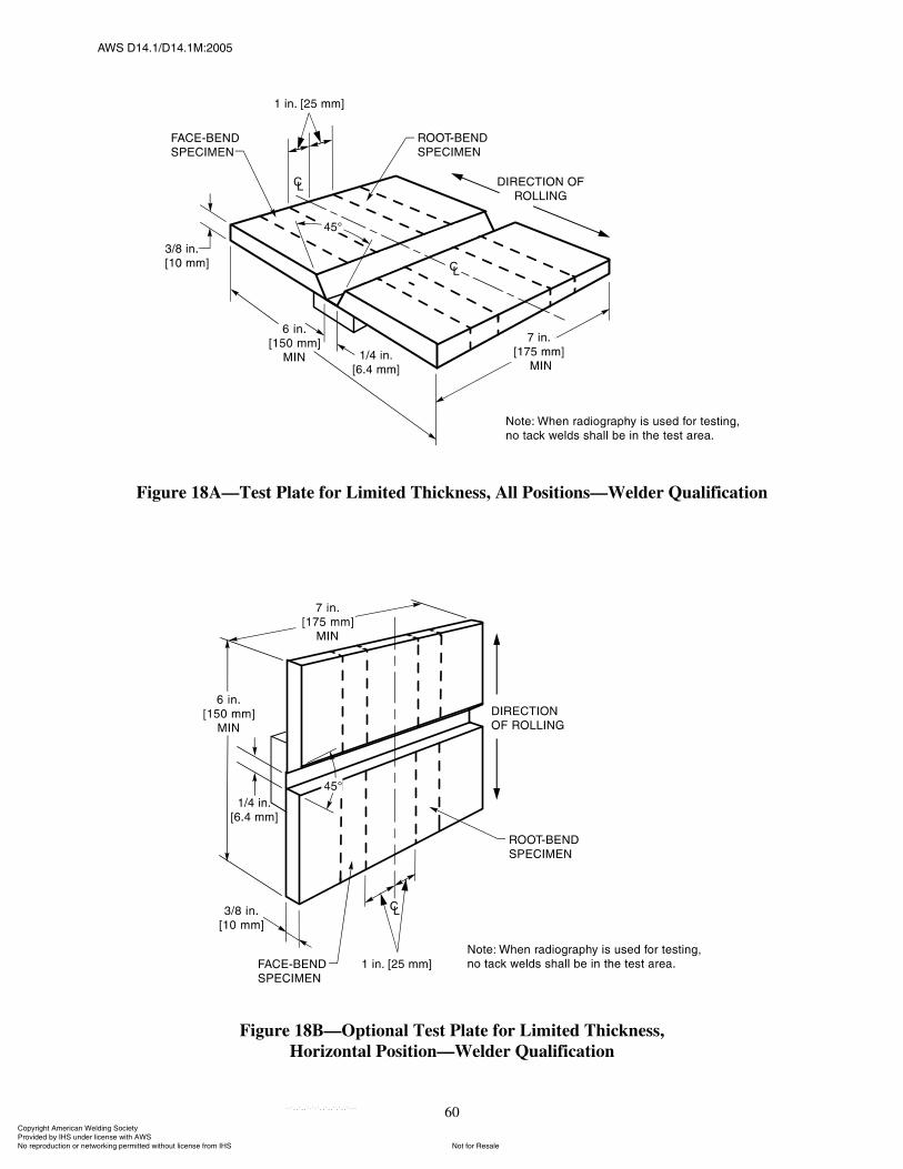
ßÉÍ ÜïìòïñÜïìòïÓæîððë
60
Figure 18A�Test Plate for Limited Thickness, All Positions�Welder Qualification
Figure 18B�Optional Test Plate for Limited Thickness,Horizontal Position�Welder Qualification
ݱ°§®·¹¸¬ ß³»®·½¿² É»´¼·²¹ ͱ½·»¬§ Ю±ª·¼»¼ ¾§ ×ØÍ «²¼»® ´·½»²» ©·¬¸ ßÉÍ
Ò±¬ º±® λ¿´»Ò± ®»°®±¼«½¬·±² ±® ²»¬©±®µ·²¹ °»®³·¬¬»¼ ©·¬¸±«¬ ´·½»²» º®±³ ×ØÍ
óóÀôôÀôôÀóÀóÀôôÀôôÀôÀôôÀóóó
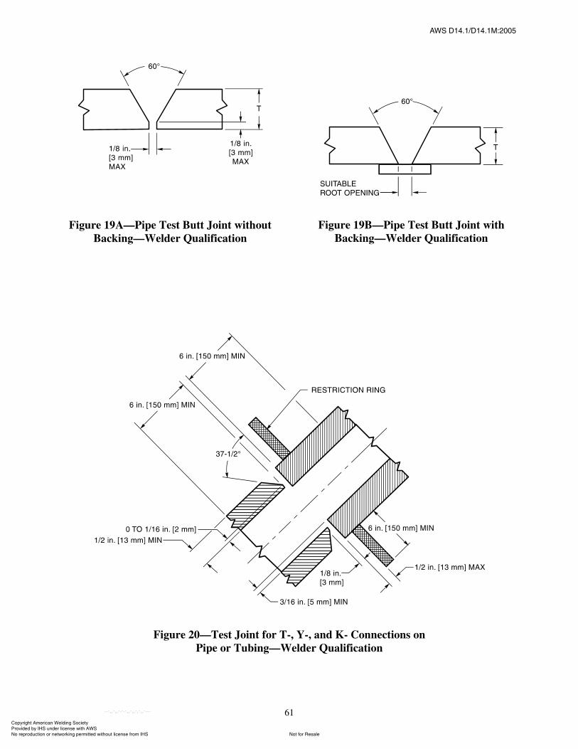
ßÉÍ ÜïìòïñÜïìòïÓæîððë
61
Figure 19A�Pipe Test Butt Joint withoutBacking�Welder Qualification
Figure 19B�Pipe Test Butt Joint withBacking�Welder Qualification
Figure 20�Test Joint for T-, Y-, and K- Connections onPipe or Tubing�Welder Qualification
ݱ°§®·¹¸¬ ß³»®·½¿² É»´¼·²¹ ͱ½·»¬§ Ю±ª·¼»¼ ¾§ ×ØÍ «²¼»® ´·½»²» ©·¬¸ ßÉÍ
Ò±¬ º±® λ¿´»Ò± ®»°®±¼«½¬·±² ±® ²»¬©±®µ·²¹ °»®³·¬¬»¼ ©·¬¸±«¬ ´·½»²» º®±³ ×ØÍ
óóÀôôÀôôÀóÀóÀôôÀôôÀôÀôôÀóóó
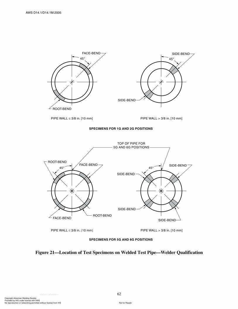
ßÉÍ ÜïìòïñÜïìòïÓæîððë
62
Figure 21�Location of Test Specimens on Welded Test Pipe�Welder Qualification
ݱ°§®·¹¸¬ ß³»®·½¿² É»´¼·²¹ ͱ½·»¬§ Ю±ª·¼»¼ ¾§ ×ØÍ «²¼»® ´·½»²» ©·¬¸ ßÉÍ
Ò±¬ º±® λ¿´»Ò± ®»°®±¼«½¬·±² ±® ²»¬©±®µ·²¹ °»®³·¬¬»¼ ©·¬¸±«¬ ´·½»²» º®±³ ×ØÍ
óóÀôôÀôôÀóÀóÀôôÀôôÀôÀôôÀóóó
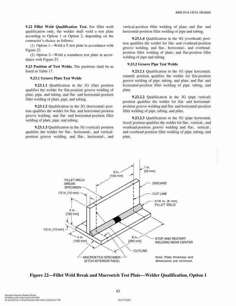
ßÉÍ ÜïìòïñÜïìòïÓæîððë
63
9.22 Fillet Weld Qualification Test. For fillet weldqualification only, the welder shall weld a test plateaccording to Option 1 or Option 2, depending on thecontractor�s choice, as follows:
(1) Option 1�Weld a T-test plate in accordance withFigure 22.
(2) Option 2�Weld a soundness test plate in accor-dance with Figure 23.
9.23 Position of Test Welds. The positions shall be aslisted in Table 17.
9.23.1 Groove Plate Test Welds
9.23.1.1 Qualification in the 1G (flat) positionqualifies the welder for flat-position groove welding ofplate, pipe, and tubing, and flat- and horizontal-positionfillet welding of plate, pipe, and tubing.
9.23.1.2 Qualification in the 2G (horizontal) posi-tion qualifies the welder for flat- and horizontal-positiongroove welding, and flat- and horizontal-position filletwelding of plate, pipe, and tubing.
9.23.1.3 Qualification in the 3G (vertical) positionqualifies the welder for flat-, horizontal-, and vertical-position groove welding, and flat-, horizontal-, and
vertical-position fillet welding of plate; and flat- andhorizontal-position fillet welding of pipe and tubing.
9.23.1.4 Qualification in the 4G (overhead) posi-tion qualifies the welder for flat- and overhead-positiongroove welding, and flat-, horizontal-, and overhead-position fillet welding of plate; and flat-position filletwelding of pipe and tubing.
9.23.2 Groove Pipe Test Welds
9.23.2.1 Qualification in the 1G (pipe horizontal,rotated) position qualifies the welder for flat-positiongroove welding of pipe, tubing, and plate; and flat- andhorizontal-position fillet welding of pipe, tubing, andplate.
9.23.2.2 Qualification in the 2G (pipe vertical)position qualifies the welder for flat- and horizontal-position groove welding and flat- and horizontal-positionfillet welding of pipe, tubing, and plate.
9.23.2.3 Qualification in the 5G (pipe horizontal,fixed) position qualifies the welder for flat-, vertical-, andoverhead-position groove welding and flat-, vertical-,and overhead-position fillet welding of pipe, tubing, andplate.
Figure 22�Fillet Weld Break and Macroetch Test Plate�Welder Qualification, Option 1
ݱ°§®·¹¸¬ ß³»®·½¿² É»´¼·²¹ ͱ½·»¬§ Ю±ª·¼»¼ ¾§ ×ØÍ «²¼»® ´·½»²» ©·¬¸ ßÉÍ
Ò±¬ º±® λ¿´»Ò± ®»°®±¼«½¬·±² ±® ²»¬©±®µ·²¹ °»®³·¬¬»¼ ©·¬¸±«¬ ´·½»²» º®±³ ×ØÍ
óóÀôôÀôôÀóÀóÀôôÀôôÀôÀôôÀóóó

ßÉÍ ÜïìòïñÜïìòïÓæîððë
64
Figure 23�Fillet Weld Root-Bend Test Plate�Welder Qualification, Option 2
ݱ°§®·¹¸¬ ß³»®·½¿² É»´¼·²¹ ͱ½·»¬§ Ю±ª·¼»¼ ¾§ ×ØÍ «²¼»® ´·½»²» ©·¬¸ ßÉÍ
Ò±¬ º±® λ¿´»Ò± ®»°®±¼«½¬·±² ±® ²»¬©±®µ·²¹ °»®³·¬¬»¼ ©·¬¸±«¬ ´·½»²» º®±³ ×ØÍ
óóÀôôÀôôÀóÀóÀôôÀôôÀôÀôôÀóóó
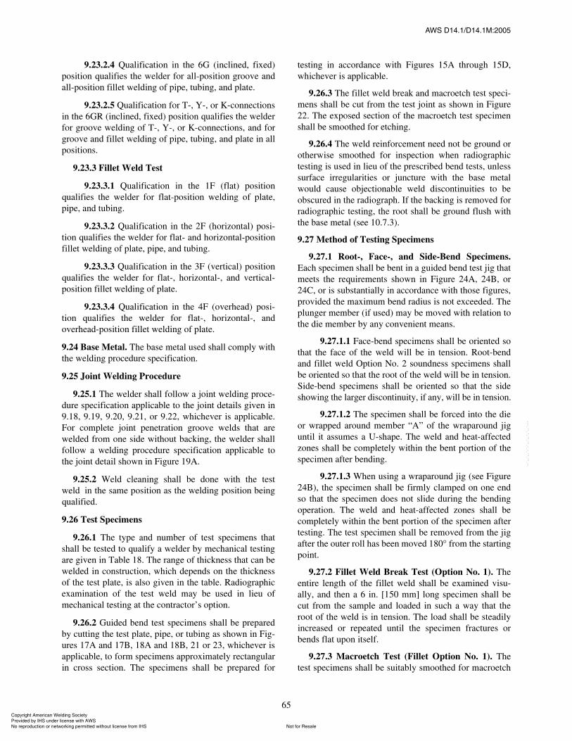
ßÉÍ ÜïìòïñÜïìòïÓæîððë
65
9.23.2.4 Qualification in the 6G (inclined, fixed)position qualifies the welder for all-position groove andall-position fillet welding of pipe, tubing, and plate.
9.23.2.5 Qualification for T-, Y-, or K-connectionsin the 6GR (inclined, fixed) position qualifies the welderfor groove welding of T-, Y-, or K-connections, and forgroove and fillet welding of pipe, tubing, and plate in allpositions.
9.23.3 Fillet Weld Test
9.23.3.1 Qualification in the 1F (flat) positionqualifies the welder for flat-position welding of plate,pipe, and tubing.
9.23.3.2 Qualification in the 2F (horizontal) posi-tion qualifies the welder for flat- and horizontal-positionfillet welding of plate, pipe, and tubing.
9.23.3.3 Qualification in the 3F (vertical) positionqualifies the welder for flat-, horizontal-, and vertical-position fillet welding of plate.
9.23.3.4 Qualification in the 4F (overhead) posi-tion qualifies the welder for flat-, horizontal-, andoverhead-position fillet welding of plate.
9.24 Base Metal. The base metal used shall comply withthe welding procedure specification.
9.25 Joint Welding Procedure
9.25.1 The welder shall follow a joint welding proce-dure specification applicable to the joint details given in9.18, 9.19, 9.20, 9.21, or 9.22, whichever is applicable.For complete joint penetration groove welds that arewelded from one side without backing, the welder shallfollow a welding procedure specification applicable tothe joint detail shown in Figure 19A.
9.25.2 Weld cleaning shall be done with the testweld in the same position as the welding position beingqualified.
9.26 Test Specimens
9.26.1 The type and number of test specimens thatshall be tested to qualify a welder by mechanical testingare given in Table 18. The range of thickness that can bewelded in construction, which depends on the thicknessof the test plate, is also given in the table. Radiographicexamination of the test weld may be used in lieu ofmechanical testing at the contractor�s option.
9.26.2 Guided bend test specimens shall be preparedby cutting the test plate, pipe, or tubing as shown in Fig-ures 17A and 17B, 18A and 18B, 21 or 23, whichever isapplicable, to form specimens approximately rectangularin cross section. The specimens shall be prepared for
testing in accordance with Figures 15A through 15D,whichever is applicable.
9.26.3 The fillet weld break and macroetch test speci-mens shall be cut from the test joint as shown in Figure22. The exposed section of the macroetch test specimenshall be smoothed for etching.
9.26.4 The weld reinforcement need not be ground orotherwise smoothed for inspection when radiographictesting is used in lieu of the prescribed bend tests, unlesssurface irregularities or juncture with the base metalwould cause objectionable weld discontinuities to beobscured in the radiograph. If the backing is removed forradiographic testing, the root shall be ground flush withthe base metal (see 10.7.3).
9.27 Method of Testing Specimens
9.27.1 Root-, Face-, and Side-Bend Specimens.Each specimen shall be bent in a guided bend test jig thatmeets the requirements shown in Figure 24A, 24B, or24C, or is substantially in accordance with those figures,provided the maximum bend radius is not exceeded. Theplunger member (if used) may be moved with relation tothe die member by any convenient means.
9.27.1.1 Face-bend specimens shall be oriented sothat the face of the weld will be in tension. Root-bendand fillet weld Option No. 2 soundness specimens shallbe oriented so that the root of the weld will be in tension.Side-bend specimens shall be oriented so that the sideshowing the larger discontinuity, if any, will be in tension.
9.27.1.2 The specimen shall be forced into the dieor wrapped around member �A� of the wraparound jiguntil it assumes a U-shape. The weld and heat-affectedzones shall be completely within the bent portion of thespecimen after bending.
9.27.1.3 When using a wraparound jig (see Figure24B), the specimen shall be firmly clamped on one endso that the specimen does not slide during the bendingoperation. The weld and heat-affected zones shall becompletely within the bent portion of the specimen aftertesting. The test specimen shall be removed from the jigafter the outer roll has been moved 180° from the startingpoint.
9.27.2 Fillet Weld Break Test (Option No. 1). Theentire length of the fillet weld shall be examined visu-ally, and then a 6 in. [150 mm] long specimen shall becut from the sample and loaded in such a way that theroot of the weld is in tension. The load shall be steadilyincreased or repeated until the specimen fractures orbends flat upon itself.
9.27.3 Macroetch Test (Fillet Option No. 1). Thetest specimens shall be suitably smoothed for macroetch
ݱ°§®·¹¸¬ ß³»®·½¿² É»´¼·²¹ ͱ½·»¬§ Ю±ª·¼»¼ ¾§ ×ØÍ «²¼»® ´·½»²» ©·¬¸ ßÉÍ
Ò±¬ º±® λ¿´»Ò± ®»°®±¼«½¬·±² ±® ²»¬©±®µ·²¹ °»®³·¬¬»¼ ©·¬¸±«¬ ´·½»²» º®±³ ×ØÍ
óóÀôôÀôôÀóÀóÀôôÀôôÀôÀôôÀóóó
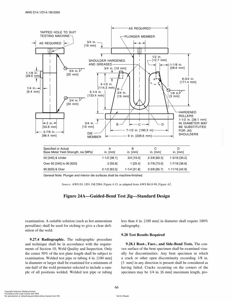
ßÉÍ ÜïìòïñÜïìòïÓæîððë
66
examination. A suitable solution (such as hot ammoniumpersulfate) shall be used for etching to give a clear defi-nition of the weld.
9.27.4 Radiographic. The radiographic procedureand technique shall be in accordance with the require-ments of Section 10, Weld Quality and Inspection. Onlythe center 50% of the test plate length shall be subject toexamination. Welded test pipe or tubing 4 in. [100 mm]in diameter or larger shall be examined for a minimum ofone-half of the weld perimeter selected to include a sam-ple of all positions welded. Welded test pipe or tubing
less than 4 in. [100 mm] in diameter shall require 100%radiography.
9.28 Test Results Required
9.28.1 Root-, Face-, and Side-Bend Tests. The con-vex surface of the bent specimen shall be examined visu-ally for discontinuities. Any bent specimen in whicha crack or other open discontinuity exceeding 1/8 in.[3 mm] in any direction is present shall be considered ashaving failed. Cracks occurring on the corners of thespecimen may be 1/4 in. [6 mm] maximum length, pro-
Source: AWS D1.1/D1.1M:2004, Figure 4.15, as adapted from AWS B4.0-98, Figure A2.
Figure 24A�Guided-Bend Test Jig�Standard Design
Í°»½·º·»¼ ±® ß½¬«¿´Þ¿» Ó»¬¿´ Ç·»´¼ ͬ®»²¹¬¸ô µ· ÅÓпÃ
ß·²ò ų³Å
Þ·²ò ų³Ã
Ý·²ò ų³Ã
Ü·²ò ų³Ã
ëð Åíìëà ú ˲¼»® ïóïñî Åíèòïà óðíñì Åïçòðà îóíñè Åêðòíà ïóíñïê ÅíðòîÃ
Ѫ»® ëð Åíìëà ¬± çð Åêîðà ðóðñî Åëðòèà ðóïñï Åîëòìà îóéñè Åéíòðà ïóéñïê ÅíêòêÃ
çð Åêîðà ú Ѫ»® îóïñî Åêíòëà ïóïñì Åíïòèà íóíñè Åèëòéà ïóïïñïê ÅìîòçÃð
Ù»²»®¿´ Ò±¬»æ д«²¹»® ¿²¼ ·²¬»®·±® ¼·» «®º¿½» ¸¿´´ ¾» ³¿½¸·²»óº·²·¸»¼ò
ݱ°§®·¹¸¬ ß³»®·½¿² É»´¼·²¹ ͱ½·»¬§ Ю±ª·¼»¼ ¾§ ×ØÍ «²¼»® ´·½»²» ©·¬¸ ßÉÍ
Ò±¬ º±® λ¿´»Ò± ®»°®±¼«½¬·±² ±® ²»¬©±®µ·²¹ °»®³·¬¬»¼ ©·¬¸±«¬ ´·½»²» º®±³ ×ØÍ
óóÀôôÀôôÀóÀóÀôôÀôôÀôÀôôÀóóó
ßÉÍ ÜïìòïñÜïìòïÓæîððë
67
vided there is no evidence of slag inclusions or otherfusion-type discontinuities.
9.28.2 Fillet Weld Break Test
9.28.2.1 To pass visual examination, the fillet weldshall present a reasonably uniform appearance and shallbe free of overlap, cracks, and excessive undercut. Thereshall be no porosity visible on the surface of the weld.
9.28.2.2 The fillet weld specimen passes the test ifit bends flat upon itself. If the fillet weld fractures, thefractured surface shall show complete fusion to the rootof the joint, and exhibit no inclusion or porosity largerthan 3/32 in. [2.5 mm] in the greatest dimension to passthe test. The sum of the greatest dimensions of allinclusions and porosity at the fractured surface shallnot exceed 3/8 in. [10 mm] in the 6 in. [150 mm] longspecimen.
9.28.3 Macroetch Test. The specimen shall be exam-ined for discontinuities. If discontinuities prohibited bySection 10, Weld Quality and Inspection, are found, thetest shall be considered as failed. The weld shall show
fusion to the root, but not necessarily beyond, and bothlegs shall be equal to within 1/8 in. [3 mm]. Convexityshall not exceed the limits specified in 10.7, e.g., 1/16 in.[2 mm] for a 5/16 in. [8 mm] test weld.
9.28.4 Radiographic Test. To qualify, the weld, asrevealed by the radiograph, shall conform to the require-ments of Section 10.
9.28.5 Visual Inspection of Pipe and Tubing (see9.12.6)
9.28.6 Visual Inspection of Plate. For acceptablequalification, the welded test plates shall conform to therequirements for visual inspection in Section 10.
9.29 Retests. If one or more test welds made by a welderfails to meet the requirements, a retest may be allowedunder the following conditions:
(1) An immediate retest may be made consisting oftwo welds of each type on which the welder failed.The retest specimens shall meet all the specifiedrequirements.
Source: AWS D1.1/D1.1M:2004, Figure 4.16, as adapted from AWS B4.0-98, Figure A1.
Figure 24B�Alternative Guided-Bend Test Jig�Wraparound Design
Í°»½·º·»¼ ±® ß½¬«¿´Þ¿» Ó»¬¿´ Ç·»´¼ ͬ®»²¹¬¸ô µ· ÅÓпÃ
ß·²ò ų³Ã
Þ·²ò ų³Ã
ëð Åíìëà ú ˲¼»® ïóïñî Åíèòïà óðíñì ÅïçòðÃ
Ѫ»® ëð Åíìëà ¬± çð Åêîðà ðóðñî Åëðòèà ðóïñï ÅîëòìÃ
çð Åêîðà ú Ѫ»® îóïñî Åêíòëà ïóïñì ÅíïòèÃ
Ù»²»®¿´ Ò±¬»æ д«²¹»® ¿²¼ ·²¬»®·±® ¼·» «®º¿½» ¸¿´´ ¾» ³¿½¸·²»óº·²·¸»¼ò
ݱ°§®·¹¸¬ ß³»®·½¿² É»´¼·²¹ ͱ½·»¬§ Ю±ª·¼»¼ ¾§ ×ØÍ «²¼»® ´·½»²» ©·¬¸ ßÉÍ
Ò±¬ º±® λ¿´»Ò± ®»°®±¼«½¬·±² ±® ²»¬©±®µ·²¹ °»®³·¬¬»¼ ©·¬¸±«¬ ´·½»²» º®±³ ×ØÍ
óóÀôôÀôôÀóÀóÀôôÀôôÀôÀôôÀóóó
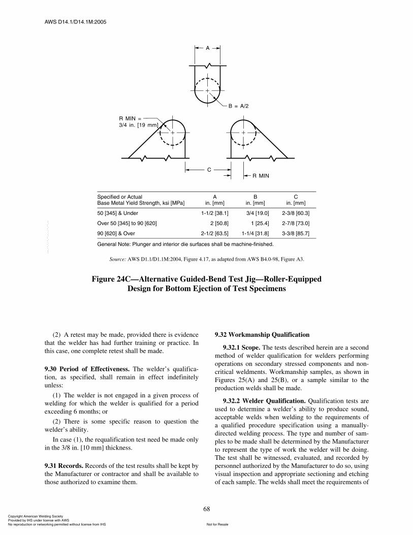
ßÉÍ ÜïìòïñÜïìòïÓæîððë
68
(2) A retest may be made, provided there is evidencethat the welder has had further training or practice. Inthis case, one complete retest shall be made.
9.30 Period of Effectiveness. The welder�s qualifica-tion, as specified, shall remain in effect indefinitelyunless:
(1) The welder is not engaged in a given process ofwelding for which the welder is qualified for a periodexceeding 6 months; or
(2) There is some specific reason to question thewelder�s ability.
In case (1), the requalification test need be made onlyin the 3/8 in. [10 mm] thickness.
9.31 Records. Records of the test results shall be kept bythe Manufacturer or contractor and shall be available tothose authorized to examine them.
9.32 Workmanship Qualification
9.32.1 Scope. The tests described herein are a secondmethod of welder qualification for welders performingoperations on secondary stressed components and non-critical weldments. Workmanship samples, as shown inFigures 25(A) and 25(B), or a sample similar to theproduction welds shall be made.
9.32.2 Welder Qualification. Qualification tests areused to determine a welder�s ability to produce sound,acceptable welds when welding to the requirements ofa qualified procedure specification using a manually-directed welding process. The type and number of sam-ples to be made shall be determined by the Manufacturerto represent the type of work the welder will be doing.The test shall be witnessed, evaluated, and recorded bypersonnel authorized by the Manufacturer to do so, usingvisual inspection and appropriate sectioning and etchingof each sample. The welds shall meet the requirements of
Source: AWS D1.1/D1.1M:2004, Figure 4.17, as adapted from AWS B4.0-98, Figure A3.
Figure 24C�Alternative Guided-Bend Test Jig�Roller-EquippedDesign for Bottom Ejection of Test Specimens
Í°»½·º·»¼ ±® ß½¬«¿´Þ¿» Ó»¬¿´ Ç·»´¼ ͬ®»²¹¬¸ô µ· ÅÓпÃ
ß·²ò ų³Ã
Þ·²ò ų³Ã
Ý·²ò ų³Ã
ëð Åíìëà ú ˲¼»® ïóïñî Åíèòïà óðíñì Åïçòðà îóíñè ÅêðòíÃ
Ѫ»® ëð Åíìëà ¬± çð Åêîðà ðóðñî Åëðòèà ðóïñï Åîëòìà îóéñè ÅéíòðÃ
çð Åêîðà ú Ѫ»® îóïñî Åêíòëà ïóïñì Åíïòèà íóíñè ÅèëòéÃ
Ù»²»®¿´ Ò±¬»æ д«²¹»® ¿²¼ ·²¬»®·±® ¼·» «®º¿½» ¸¿´´ ¾» ³¿½¸·²»óº·²·¸»¼ò
ݱ°§®·¹¸¬ ß³»®·½¿² É»´¼·²¹ ͱ½·»¬§ Ю±ª·¼»¼ ¾§ ×ØÍ «²¼»® ´·½»²» ©·¬¸ ßÉÍ
Ò±¬ º±® λ¿´»Ò± ®»°®±¼«½¬·±² ±® ²»¬©±®µ·²¹ °»®³·¬¬»¼ ©·¬¸±«¬ ´·½»²» º®±³ ×ØÍ
óóÀôôÀôôÀóÀóÀôôÀôôÀôÀôôÀóóó
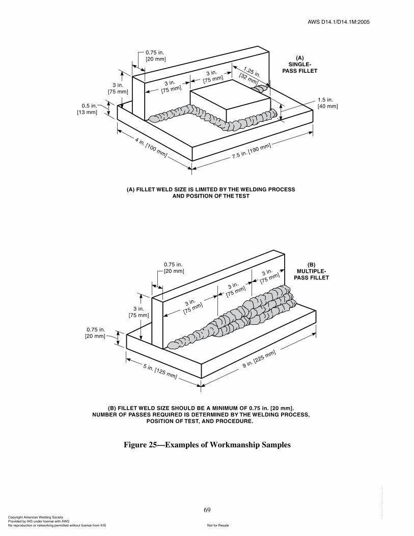
ßÉÍ ÜïìòïñÜïìòïÓæîððë
69
Figure 25�Examples of Workmanship Samples
ݱ°§®·¹¸¬ ß³»®·½¿² É»´¼·²¹ ͱ½·»¬§ Ю±ª·¼»¼ ¾§ ×ØÍ «²¼»® ´·½»²» ©·¬¸ ßÉÍ
Ò±¬ º±® λ¿´»Ò± ®»°®±¼«½¬·±² ±® ²»¬©±®µ·²¹ °»®³·¬¬»¼ ©·¬¸±«¬ ´·½»²» º®±³ ×ØÍ
óóÀôôÀôôÀóÀóÀôôÀôôÀôÀôôÀóóó
ßÉÍ ÜïìòïñÜïìòïÓæîððë
70
Sections 7 (Workmanship) and 10 (Weld Quality andInspection).
9.32.3 Production Qualification. After successfulcompletion of one or more workmanship samples, thecapability of the welder to satisfactorily perform produc-tion welding will be determined after a tryout at the jobstation. Qualification shall be achieved when the welderproduces a typical production part that meets the qualityrequirements of this specification, as witnessed andrecorded by personnel authorized by the Manufacturer todo so.
9.32.4 Sample Examination. Methods of examiningsamples shall be visual, sectioning and etching, andphysical measurement.
9.32.4.1 Visual Examination. To pass the visualexamination, the weld shall meet the requirements ofSection 7 (Workmanship) and Section 10 (Weld Qualityand Inspection).
9.32.4.2 Macroetch Examination. The specimencross section shall be smoothed, etched, and examinedfor discontinuities. The sample shall meet the applicablerequirements in other sections of this specification. Theweld shall show complete fusion to the root, but not nec-essarily beyond. Convexity and concavity of the weldshall not exceed the limits specified in Sections 7 and 10.
9.32.4.3 Physical Measurement Examination.Welds shall be measured to ascertain that they meet thesize tolerances specified in Sections 7 and 10.
9.32.5 Retests. In case one or more test welds fail tomeet the requirements of 9.32.4, the welder may beretested under the following conditions:
(1) An immediate retest may be made that shall con-sist of two test welds of each type that failed. Both testspecimens shall meet all the requirements specified forsuch welds.
(2) A retest may be made, provided there is evidencethat the welder has had further training or practice. Inthis case, one complete retest shall be made.
9.32.6 Period of Effectiveness. Welder qualificationverified by workmanship samples shall remain in effectindefinitely unless:
(1) The welder does not use a welding process forwhich the welder is qualified for a period exceeding sixmonths; or
(2) There is some specific reason to question thewelder�s ability.
In case (1), the requalification test need be made onlywith 3/8 in. [10 mm] thick material.
9.32.7 Records. Records of the test results shall bekept by the Manufacturer and shall be available to those
authorized to examine them (see suggested sample formin Annex A).
Part DWelding Operator Qualification
9.33 General. The qualification tests described in thissection are specially devised to determine a weldingoperator�s ability to produce sound welds. The tests arenot intended to be used as a guide for welding duringactual construction. The latter shall be performed inaccordance with the requirements of the procedure speci-fication. For an alternate method of qualification, see9.32.
9.34 Limitations. For the qualification of a weldingoperator, the following rules shall apply:
(1) Qualification established with any one of thesteels permitted by this specification shall be consideredas qualification to weld any of the other steels.
(2) A welding operator qualified with an approvedelectrode-shielding medium combination shall be con-sidered qualified to weld with any other approved elec-trode-shielding medium combination for the processused in the qualification test.
(3) A welding operator qualified to weld with multi-ple electrodes or welding heads shall be qualified to weldwith a single electrode, but not vice versa. This does notapply to electrogas and electroslag welding.
(4) An electroslag or electrogas welding operatorqualified with an approved electrode-shielding mediumcombination shall be considered qualified to weld withany other approved electrode-shielding medium combi-nation for the process used in the qualification test.
(5) A change in the position in which welding is doneshall require qualification in the new position (see9.35.3).
9.35 Qualification Tests Required
9.35.1 The welding operator qualification test, forother than electroslag or electrogas welding, shall havethe following joint detail: 1 in. [25 mm] plate, single-V-groove, 20° groove angle, and 5/8 in. [16 mm] root open-ing with backing (see Figure 26). Backing shall be atleast 3/8 in. [10 mm] I 3 in. [75 mm] if radiographic test-ing is used without prior removal of backing. It shall beat least 3/8 in. [10 mm] I 2 in. [50 mm] for mechanicaland ultrasonic testing and for radiographic testing afterthe backing is removed. Minimum length of the weldinggroove shall be 15 in. [375 mm]. This test will qualifythe welding operator for groove and fillet welding in
ݱ°§®·¹¸¬ ß³»®·½¿² É»´¼·²¹ ͱ½·»¬§ Ю±ª·¼»¼ ¾§ ×ØÍ «²¼»® ´·½»²» ©·¬¸ ßÉÍ
Ò±¬ º±® λ¿´»Ò± ®»°®±¼«½¬·±² ±® ²»¬©±®µ·²¹ °»®³·¬¬»¼ ©·¬¸±«¬ ´·½»²» º®±³ ×ØÍ
óóÀôôÀôôÀóÀóÀôôÀôôÀôÀôôÀóóó
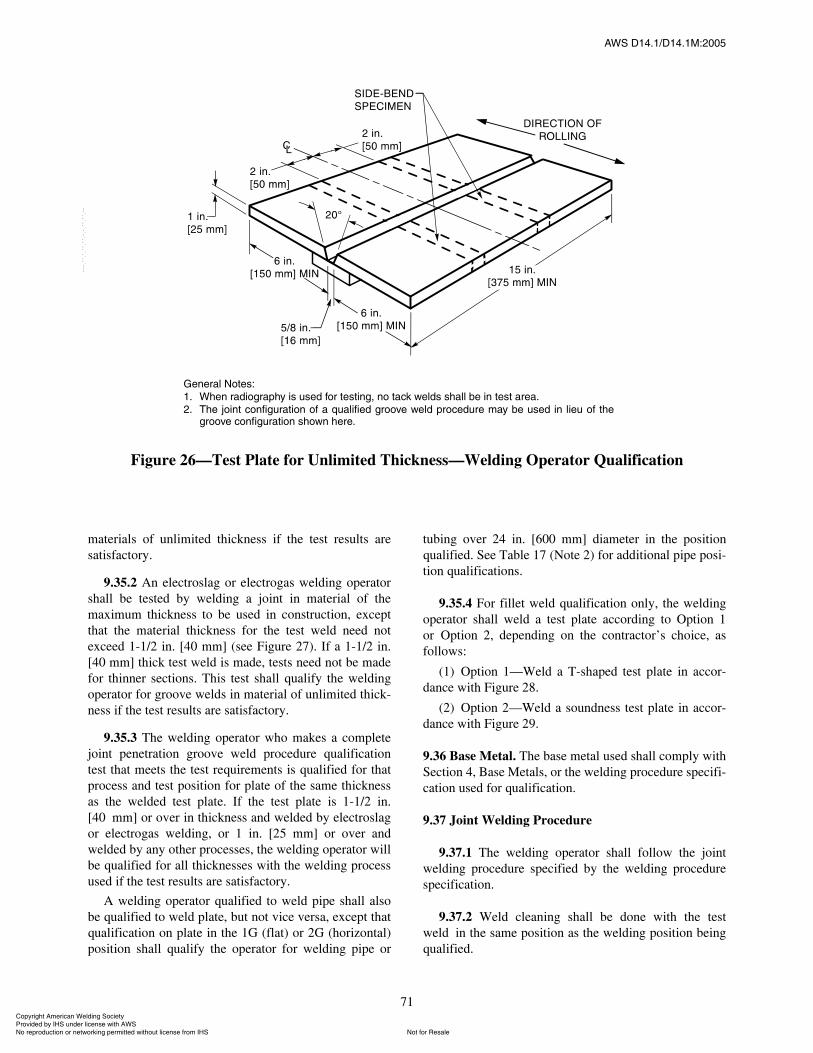
ßÉÍ ÜïìòïñÜïìòïÓæîððë
71
materials of unlimited thickness if the test results aresatisfactory.
9.35.2 An electroslag or electrogas welding operatorshall be tested by welding a joint in material of themaximum thickness to be used in construction, exceptthat the material thickness for the test weld need notexceed 1-1/2 in. [40 mm] (see Figure 27). If a 1-1/2 in.[40 mm] thick test weld is made, tests need not be madefor thinner sections. This test shall qualify the weldingoperator for groove welds in material of unlimited thick-ness if the test results are satisfactory.
9.35.3 The welding operator who makes a completejoint penetration groove weld procedure qualificationtest that meets the test requirements is qualified for thatprocess and test position for plate of the same thicknessas the welded test plate. If the test plate is 1-1/2 in.[40 mm] or over in thickness and welded by electroslagor electrogas welding, or 1 in. [25 mm] or over andwelded by any other processes, the welding operator willbe qualified for all thicknesses with the welding processused if the test results are satisfactory.
A welding operator qualified to weld pipe shall alsobe qualified to weld plate, but not vice versa, except thatqualification on plate in the 1G (flat) or 2G (horizontal)position shall qualify the operator for welding pipe or
tubing over 24 in. [600 mm] diameter in the positionqualified. See Table 17 (Note 2) for additional pipe posi-tion qualifications.
9.35.4 For fillet weld qualification only, the weldingoperator shall weld a test plate according to Option 1or Option 2, depending on the contractor�s choice, asfollows:
(1) Option 1�Weld a T-shaped test plate in accor-dance with Figure 28.
(2) Option 2�Weld a soundness test plate in accor-dance with Figure 29.
9.36 Base Metal. The base metal used shall comply withSection 4, Base Metals, or the welding procedure specifi-cation used for qualification.
9.37 Joint Welding Procedure
9.37.1 The welding operator shall follow the jointwelding procedure specified by the welding procedurespecification.
9.37.2 Weld cleaning shall be done with the testweld in the same position as the welding position beingqualified.
Ù»²»®¿´ Ò±¬»æ
ïò ɸ»² ®¿¼·±¹®¿°¸§ · «»¼ º±® ¬»¬·²¹ô ²± ¬¿½µ ©»´¼ ¸¿´´ ¾» ·² ¬»¬ ¿®»¿ò
îò ̸» ¶±·²¬ ½±²º·¹«®¿¬·±² ±º ¿ ¯«¿´·º·»¼ ¹®±±ª» ©»´¼ °®±½»¼«®» ³¿§ ¾» «»¼ ·² ´·»« ±º ¬¸»¹®±±ª» ½±²º·¹«®¿¬·±² ¸±©² ¸»®»ò
Figure 26�Test Plate for Unlimited Thickness�Welding Operator Qualification
ݱ°§®·¹¸¬ ß³»®·½¿² É»´¼·²¹ ͱ½·»¬§ Ю±ª·¼»¼ ¾§ ×ØÍ «²¼»® ´·½»²» ©·¬¸ ßÉÍ
Ò±¬ º±® λ¿´»Ò± ®»°®±¼«½¬·±² ±® ²»¬©±®µ·²¹ °»®³·¬¬»¼ ©·¬¸±«¬ ´·½»²» º®±³ ×ØÍ
óóÀôôÀôôÀóÀóÀôôÀôôÀôÀôôÀóóó
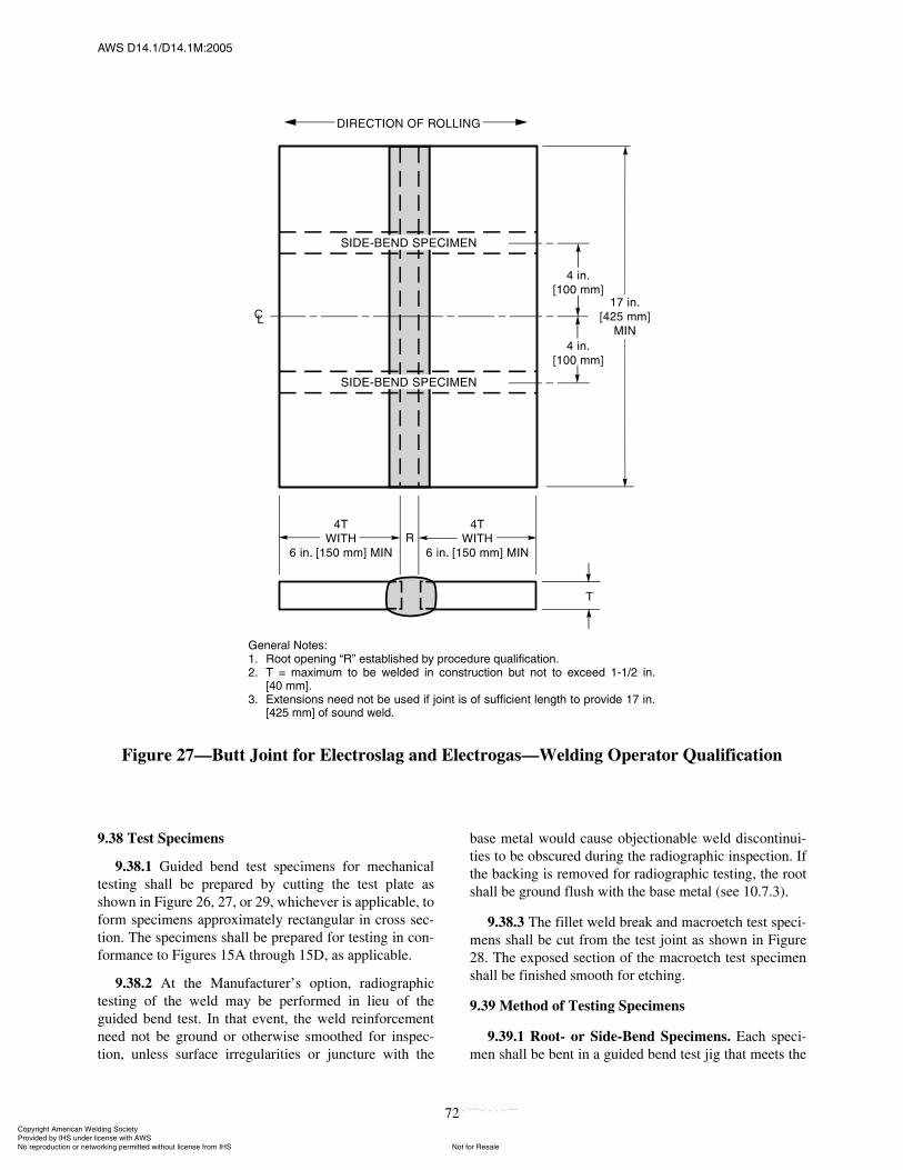
ßÉÍ ÜïìòïñÜïìòïÓæîððë
72
9.38 Test Specimens
9.38.1 Guided bend test specimens for mechanicaltesting shall be prepared by cutting the test plate asshown in Figure 26, 27, or 29, whichever is applicable, toform specimens approximately rectangular in cross sec-tion. The specimens shall be prepared for testing in con-formance to Figures 15A through 15D, as applicable.
9.38.2 At the Manufacturer�s option, radiographictesting of the weld may be performed in lieu of theguided bend test. In that event, the weld reinforcementneed not be ground or otherwise smoothed for inspec-tion, unless surface irregularities or juncture with the
base metal would cause objectionable weld discontinui-ties to be obscured during the radiographic inspection. Ifthe backing is removed for radiographic testing, the rootshall be ground flush with the base metal (see 10.7.3).
9.38.3 The fillet weld break and macroetch test speci-mens shall be cut from the test joint as shown in Figure28. The exposed section of the macroetch test specimenshall be finished smooth for etching.
9.39 Method of Testing Specimens
9.39.1 Root- or Side-Bend Specimens. Each speci-men shall be bent in a guided bend test jig that meets the
Ù»²»®¿´ Ò±¬»æïò ᱬ ±°»²·²¹ �Î� »¬¿¾´·¸»¼ ¾§ °®±½»¼«®» ¯«¿´·º·½¿¬·±²òîò Ì ã ³¿¨·³«³ ¬± ¾» ©»´¼»¼ ·² ½±²¬®«½¬·±² ¾«¬ ²±¬ ¬± »¨½»»¼ ïóïñî ·²ò
Åìð ³³Ãòíò Û¨¬»²·±² ²»»¼ ²±¬ ¾» «»¼ ·º ¶±·²¬ · ±º «ºº·½·»²¬ ´»²¹¬¸ ¬± °®±ª·¼» ïé ·²ò
Åìîë ³³Ã ±º ±«²¼ ©»´¼ò
Figure 27�Butt Joint for Electroslag and Electrogas�Welding Operator Qualification
ݱ°§®·¹¸¬ ß³»®·½¿² É»´¼·²¹ ͱ½·»¬§ Ю±ª·¼»¼ ¾§ ×ØÍ «²¼»® ´·½»²» ©·¬¸ ßÉÍ
Ò±¬ º±® λ¿´»Ò± ®»°®±¼«½¬·±² ±® ²»¬©±®µ·²¹ °»®³·¬¬»¼ ©·¬¸±«¬ ´·½»²» º®±³ ×ØÍ
óóÀôôÀôôÀóÀóÀôôÀôôÀôÀôôÀóóó
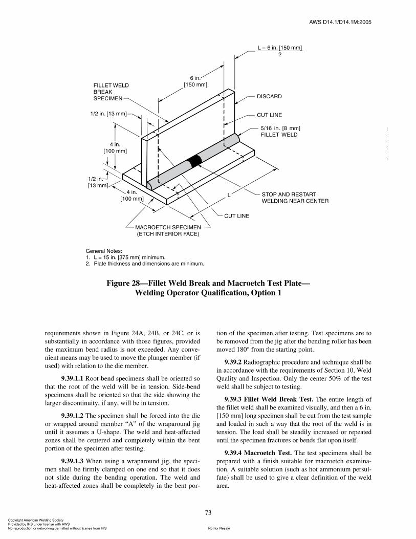
ßÉÍ ÜïìòïñÜïìòïÓæîððë
73
requirements shown in Figure 24A, 24B, or 24C, or issubstantially in accordance with those figures, providedthe maximum bend radius is not exceeded. Any conve-nient means may be used to move the plunger member (ifused) with relation to the die member.
9.39.1.1 Root-bend specimens shall be oriented sothat the root of the weld will be in tension. Side-bendspecimens shall be oriented so that the side showing thelarger discontinuity, if any, will be in tension.
9.39.1.2 The specimen shall be forced into the dieor wrapped around member �A� of the wraparound jiguntil it assumes a U-shape. The weld and heat-affectedzones shall be centered and completely within the bentportion of the specimen after testing.
9.39.1.3 When using a wraparound jig, the speci-men shall be firmly clamped on one end so that it doesnot slide during the bending operation. The weld andheat-affected zones shall be completely in the bent por-
tion of the specimen after testing. Test specimens are tobe removed from the jig after the bending roller has beenmoved 180° from the starting point.
9.39.2 Radiographic procedure and technique shall bein accordance with the requirements of Section 10, WeldQuality and Inspection. Only the center 50% of the testweld shall be subject to testing.
9.39.3 Fillet Weld Break Test. The entire length ofthe fillet weld shall be examined visually, and then a 6 in.[150 mm] long specimen shall be cut from the test sampleand loaded in such a way that the root of the weld is intension. The load shall be steadily increased or repeateduntil the specimen fractures or bends flat upon itself.
9.39.4 Macroetch Test. The test specimens shall beprepared with a finish suitable for macroetch examina-tion. A suitable solution (such as hot ammonium persul-fate) shall be used to give a clear definition of the weldarea.
Ù»²»®¿´ Ò±¬»æïò Ô ã ïë ·²ò Åíéë ³³Ã ³·²·³«³òîò д¿¬» ¬¸·½µ²» ¿²¼ ¼·³»²·±² ¿®» ³·²·³«³ò
Figure 28�Fillet Weld Break and Macroetch Test Plate�Welding Operator Qualification, Option 1
ݱ°§®·¹¸¬ ß³»®·½¿² É»´¼·²¹ ͱ½·»¬§ Ю±ª·¼»¼ ¾§ ×ØÍ «²¼»® ´·½»²» ©·¬¸ ßÉÍ
Ò±¬ º±® λ¿´»Ò± ®»°®±¼«½¬·±² ±® ²»¬©±®µ·²¹ °»®³·¬¬»¼ ©·¬¸±«¬ ´·½»²» º®±³ ×ØÍ
óóÀôôÀôôÀóÀóÀôôÀôôÀôÀôôÀóóó
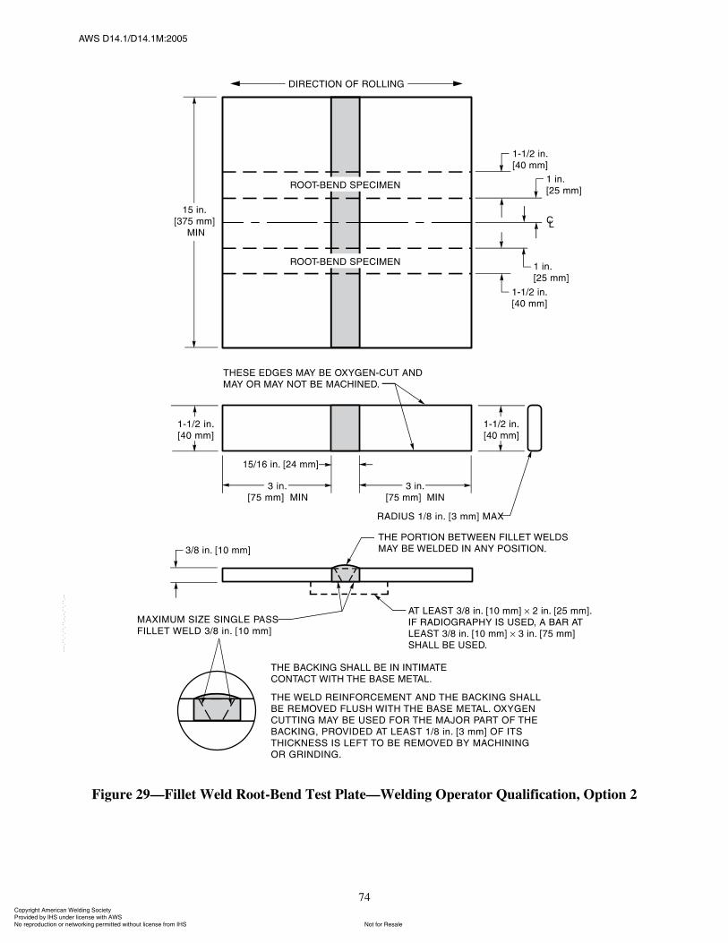
ßÉÍ ÜïìòïñÜïìòïÓæîððë
74
Figure 29�Fillet Weld Root-Bend Test Plate�Welding Operator Qualification, Option 2
ݱ°§®·¹¸¬ ß³»®·½¿² É»´¼·²¹ ͱ½·»¬§ Ю±ª·¼»¼ ¾§ ×ØÍ «²¼»® ´·½»²» ©·¬¸ ßÉÍ
Ò±¬ º±® λ¿´»Ò± ®»°®±¼«½¬·±² ±® ²»¬©±®µ·²¹ °»®³·¬¬»¼ ©·¬¸±«¬ ´·½»²» º®±³ ×ØÍ
óóÀôôÀôôÀóÀóÀôôÀôôÀôÀôôÀóóó
ßÉÍ ÜïìòïñÜïìòïÓæîððë
75
9.40 Test Results Required
9.40.1 Root- and Side-Bend Test. The convex sur-face of the specimen shall be examined for the appear-ance of cracks or other open discontinuities. Any bentspecimen containing a crack or other open discontinuityexceeding 1/8 in. [3 mm], measured in any direction,shall be considered as failed. Cracks occurring on thecorners of the specimen may be 1/4 in. [6 mm] maximumlength, provided there is no evidence of slag inclusionsor other fusion-type discontinuities.
9.40.2 Welds examined by radiographic examinationshall conform to the requirements of Section 10, WeldQuality and Inspection.
9.40.3 Fillet Weld Break Test
9.40.3.1 To pass the visual examination, the filletweld shall present a reasonably uniform appearance andshall be free of overlap, cracks, and excessive undercut.There shall be no porosity visible on the face of the weld.
9.40.3.2 The specimen passes the test if it bendsflat upon itself. If the fillet weld fractures, the fracturedsurface shall show complete fusion to the root of thejoint, and shall exhibit no inclusion or porosity largerthan 3/32 in. [2.5 mm] in the greatest dimension. Thesum of the greatest dimensions of all inclusions andporosity shall not exceed 3/8 in. [10 mm] in the 6 in.[150 mm] long specimen.
9.40.4 Macroetch Test. The test specimen shall beexamined for discontinuities. If any discontinuities pro-hibited by 10.6 are found on the surface, the specimenshall be considered to have failed. The weld shall showcomplete fusion to the root, but not necessarily beyond,and both legs shall be equal within 1/8 in. [3 mm]. Con-vexity shall not exceed the limits specified in 10.7.
9.40.5 Visual Inspection. For acceptable qualifica-tion, the welded test plate, when inspected visually, shallconform to the requirements for visual inspection in Sec-tion 10, Weld Quality and Inspection.
9.41 Retests. If one or more test welds made by a weld-ing operator fail to meet the requirements, a retest maybe allowed under the following conditions:
(1) An immediate retest may be made consisting oftwo test welds of each type on which the welding opera-tor failed. The retest specimens shall meet all the require-ments specified for such welds.
(2) A retest may be made, provided there is evidencethat the welding operator has had further training or prac-tice. In this case, one complete retest shall be made.
9.42 Period of Effectiveness. The welding operator�squalification specified in this section shall remain ineffect indefinitely unless:
(1) The welding operator is not engaged in a givenprocess of welding for which the operator is qualified fora period exceeding 6 months; or
(2) There is some specific reason to question thewelding operator�s ability.
9.43 Records. Records of the test results shall be kept bythe Manufacturer and shall be available to those autho-rized to examine them (see suggested sample form inAnnex A).
Part EQualification of Tack Welders
9.44 General. The qualification tests described in thissection are specifically devised to determine a tackwelder�s ability to produce sound tack welds. The quali-fication tests are not intended to be used as a guide fortack welding during actual construction. The latter shallbe performed in accordance with the requirements of thewelding procedure specification. For an alternate methodof qualification, see 9.32.
9.45 Limitations. For the qualification of a tack welder,the following rules apply:
9.45.1 Qualification established with any one of thesteels permitted by this specification shall qualify thetack welder to tack weld any of the other steels.
9.45.2 Qualification of a tack welder for SMAW withan electrode identified in Table 16 shall qualify the tackwelder to tack weld with any other electrode in the samegroup designation and with any electrode listed in anumerically lower group designation.
9.45.3 Qualification of a tack welder with anapproved electrode-shielding medium combination shallqualify the tack welder to tack weld with any otherapproved electrode-shielding medium combination forthe process used in the qualification test.
9.45.4 A tack welder shall be qualified for each pro-cess used.
9.45.5 A change in the position in which tack weldingis done, as defined in 9.8, shall require qualification inthe new position.
9.46 Qualification Tests Required. A tack welder shallbe qualified by making one test specimen in each posi-tion in which he or she will tack weld on the job.
9.47 Base Metal. The base metal used shall comply withthe welding procedure specification.
ݱ°§®·¹¸¬ ß³»®·½¿² É»´¼·²¹ ͱ½·»¬§ Ю±ª·¼»¼ ¾§ ×ØÍ «²¼»® ´·½»²» ©·¬¸ ßÉÍ
Ò±¬ º±® λ¿´»Ò± ®»°®±¼«½¬·±² ±® ²»¬©±®µ·²¹ °»®³·¬¬»¼ ©·¬¸±«¬ ´·½»²» º®±³ ×ØÍ
óóÀôôÀôôÀóÀóÀôôÀôôÀôÀôôÀóóó
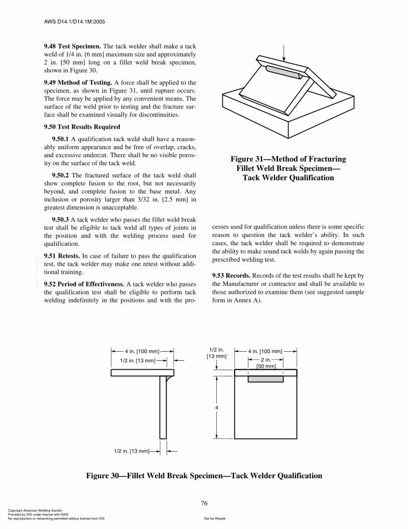
ßÉÍ ÜïìòïñÜïìòïÓæîððë
76
9.48 Test Specimen. The tack welder shall make a tackweld of 1/4 in. [6 mm] maximum size and approximately2 in. [50 mm] long on a fillet weld break specimen,shown in Figure 30.
9.49 Method of Testing. A force shall be applied to thespecimen, as shown in Figure 31, until rupture occurs.The force may be applied by any convenient means. Thesurface of the weld prior to testing and the fracture sur-face shall be examined visually for discontinuities.
9.50 Test Results Required
9.50.1 A qualification tack weld shall have a reason-ably uniform appearance and be free of overlap, cracks,and excessive undercut. There shall be no visible poros-ity on the surface of the tack weld.
9.50.2 The fractured surface of the tack weld shallshow complete fusion to the root, but not necessarilybeyond, and complete fusion to the base metal. Anyinclusion or porosity larger than 3/32 in. [2.5 mm] ingreatest dimension is unacceptable.
9.50.3 A tack welder who passes the fillet weld breaktest shall be eligible to tack weld all types of joints inthe position and with the welding process used forqualification.
9.51 Retests. In case of failure to pass the qualificationtest, the tack welder may make one retest without addi-tional training.
9.52 Period of Effectiveness. A tack welder who passesthe qualification test shall be eligible to perform tackwelding indefinitely in the positions and with the pro-
cesses used for qualification unless there is some specificreason to question the tack welder�s ability. In suchcases, the tack welder shall be required to demonstratethe ability to make sound tack welds by again passing theprescribed welding test.
9.53 Records. Records of the test results shall be kept bythe Manufacturer or contractor and shall be available tothose authorized to examine them (see suggested sampleform in Annex A).
Figure 30�Fillet Weld Break Specimen�Tack Welder Qualification
Figure 31�Method of FracturingFillet Weld Break Specimen�
Tack Welder Qualification
ݱ°§®·¹¸¬ ß³»®·½¿² É»´¼·²¹ ͱ½·»¬§ Ю±ª·¼»¼ ¾§ ×ØÍ «²¼»® ´·½»²» ©·¬¸ ßÉÍ
Ò±¬ º±® λ¿´»Ò± ®»°®±¼«½¬·±² ±® ²»¬©±®µ·²¹ °»®³·¬¬»¼ ©·¬¸±«¬ ´·½»²» º®±³ ×ØÍ
óóÀôôÀôôÀóÀóÀôôÀôôÀôÀôôÀóóó
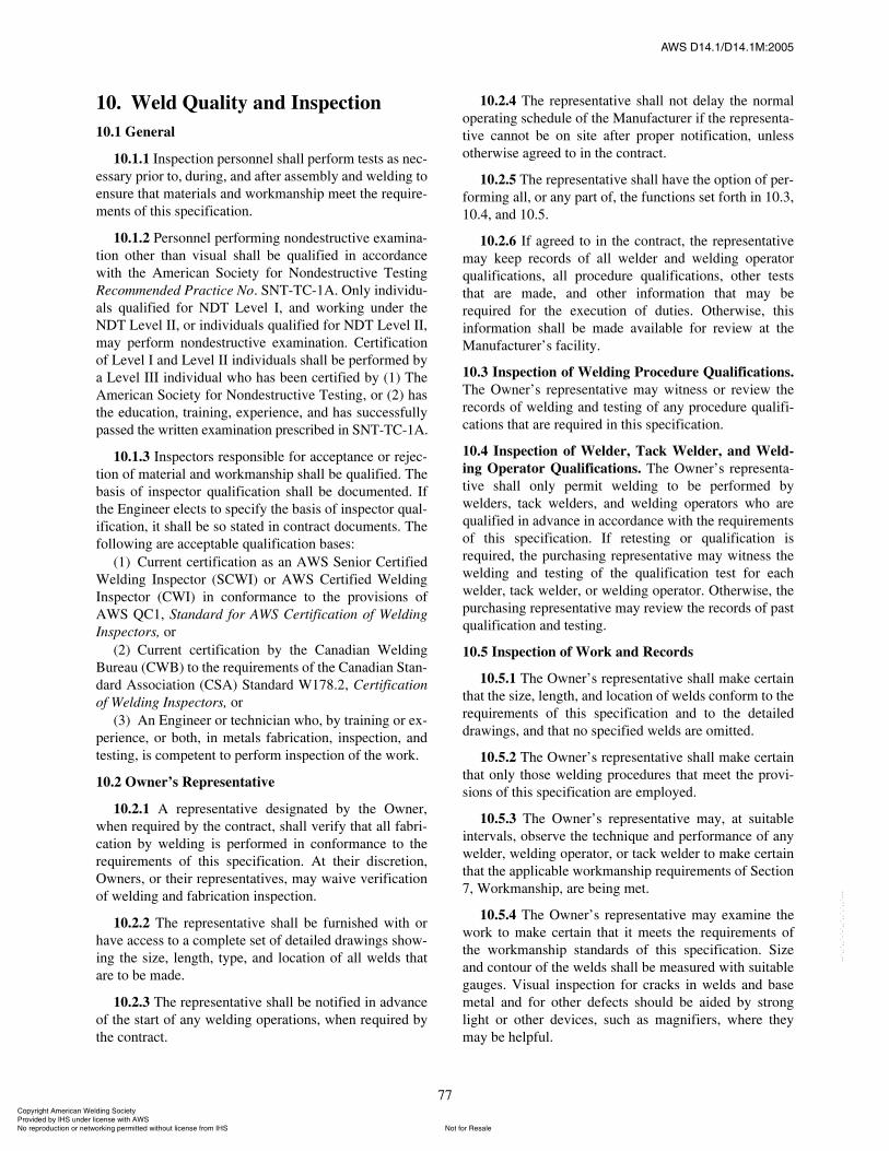
ßÉÍ ÜïìòïñÜïìòïÓæîððë
77
10. Weld Quality and Inspection10.1 General
10.1.1 Inspection personnel shall perform tests as nec-essary prior to, during, and after assembly and welding toensure that materials and workmanship meet the require-ments of this specification.
10.1.2 Personnel performing nondestructive examina-tion other than visual shall be qualified in accordancewith the American Society for Nondestructive TestingRecommended Practice No. SNT-TC-1A. Only individu-als qualified for NDT Level I, and working under theNDT Level II, or individuals qualified for NDT Level II,may perform nondestructive examination. Certificationof Level I and Level II individuals shall be performed bya Level III individual who has been certified by (1) TheAmerican Society for Nondestructive Testing, or (2) hasthe education, training, experience, and has successfullypassed the written examination prescribed in SNT-TC-1A.
10.1.3 Inspectors responsible for acceptance or rejec-tion of material and workmanship shall be qualified. Thebasis of inspector qualification shall be documented. Ifthe Engineer elects to specify the basis of inspector qual-ification, it shall be so stated in contract documents. Thefollowing are acceptable qualification bases:
(1) Current certification as an AWS Senior CertifiedWelding Inspector (SCWI) or AWS Certified WeldingInspector (CWI) in conformance to the provisions ofAWS QC1, Standard for AWS Certification of WeldingInspectors, or
(2) Current certification by the Canadian WeldingBureau (CWB) to the requirements of the Canadian Stan-dard Association (CSA) Standard W178.2, Certificationof Welding Inspectors, or
(3) An Engineer or technician who, by training or ex-perience, or both, in metals fabrication, inspection, andtesting, is competent to perform inspection of the work.
10.2 Owner�s Representative
10.2.1 A representative designated by the Owner,when required by the contract, shall verify that all fabri-cation by welding is performed in conformance to therequirements of this specification. At their discretion,Owners, or their representatives, may waive verificationof welding and fabrication inspection.
10.2.2 The representative shall be furnished with orhave access to a complete set of detailed drawings show-ing the size, length, type, and location of all welds thatare to be made.
10.2.3 The representative shall be notified in advanceof the start of any welding operations, when required bythe contract.
10.2.4 The representative shall not delay the normaloperating schedule of the Manufacturer if the representa-tive cannot be on site after proper notification, unlessotherwise agreed to in the contract.
10.2.5 The representative shall have the option of per-forming all, or any part of, the functions set forth in 10.3,10.4, and 10.5.
10.2.6 If agreed to in the contract, the representativemay keep records of all welder and welding operatorqualifications, all procedure qualifications, other teststhat are made, and other information that may berequired for the execution of duties. Otherwise, thisinformation shall be made available for review at theManufacturer�s facility.
10.3 Inspection of Welding Procedure Qualifications.The Owner�s representative may witness or review therecords of welding and testing of any procedure qualifi-cations that are required in this specification.
10.4 Inspection of Welder, Tack Welder, and Weld-ing Operator Qualifications. The Owner�s representa-tive shall only permit welding to be performed bywelders, tack welders, and welding operators who arequalified in advance in accordance with the requirementsof this specification. If retesting or qualification isrequired, the purchasing representative may witness thewelding and testing of the qualification test for eachwelder, tack welder, or welding operator. Otherwise, thepurchasing representative may review the records of pastqualification and testing.
10.5 Inspection of Work and Records
10.5.1 The Owner�s representative shall make certainthat the size, length, and location of welds conform to therequirements of this specification and to the detaileddrawings, and that no specified welds are omitted.
10.5.2 The Owner�s representative shall make certainthat only those welding procedures that meet the provi-sions of this specification are employed.
10.5.3 The Owner�s representative may, at suitableintervals, observe the technique and performance of anywelder, welding operator, or tack welder to make certainthat the applicable workmanship requirements of Section7, Workmanship, are being met.
10.5.4 The Owner�s representative may examine thework to make certain that it meets the requirements ofthe workmanship standards of this specification. Sizeand contour of the welds shall be measured with suitablegauges. Visual inspection for cracks in welds and basemetal and for other defects should be aided by stronglight or other devices, such as magnifiers, where theymay be helpful.
ݱ°§®·¹¸¬ ß³»®·½¿² É»´¼·²¹ ͱ½·»¬§ Ю±ª·¼»¼ ¾§ ×ØÍ «²¼»® ´·½»²» ©·¬¸ ßÉÍ
Ò±¬ º±® λ¿´»Ò± ®»°®±¼«½¬·±² ±® ²»¬©±®µ·²¹ °»®³·¬¬»¼ ©·¬¸±«¬ ´·½»²» º®±³ ×ØÍ
óóÀôôÀôôÀóÀóÀôôÀôôÀôÀôôÀóóó

ßÉÍ ÜïìòïñÜïìòïÓæîððë
78
10.5.5 The Owner�s representative should identify allparts or joints that have been inspected and accepted witha distinguishing mark.
10.6 Visual Examination. All welds shall be visuallyexamined. Examination shall be performed after removalof foreign debris, including slag. A weld shall be accept-able by visual examination if it meets the specified sizeon the drawings (see Section 7, Workmanship), and thefollowing conditions are met:
(1) The weld has no cracks.(2) Complete fusion exists between adjacent layers of
weld metal and between weld metal and base metal.(3) All craters are filled to the full cross section of the
weld.(4) Weld profiles are in accordance with 10.7.(5) Permissible frequency and size of piping porosity
in fillet welds shall be limited as follows:(a) For primary welds, no more than 1 pore in
each 4 in. [100 mm] of length, and no larger in diameterthan 3/32 in. [2.5 mm].
(b) For secondary welds, the sum of the diame-ters of piping porosity shall not exceed 3/8 in. [10 mm]in any linear inch of weld, and shall not exceed 3/4 in.[20 mm] in any 12 in. [300 mm] length of weld.
(6) The actual size of a portion of continuous filletweld, 3/8 in. [10 mm] or larger, can be under the nominalrequired fillet weld size by 1/16 in. [2 mm] without cor-rection, provided that the undersize portion does notexceed 10% of the weld length. On web-to-flange filletwelds on girders, no undersize weld is permitted at theend of the joint in a length equal to twice the width of theflange.
(7) Primary groove welds shall have no piping poros-ity. Secondary groove welds shall meet the porosityrequirements for fillet welds in 10.6(5)(a).
(8) Visual inspection of welds in all steels may beginimmediately after the completed welds have cooled toambient temperature. Acceptance criteria for ASTM A514, A 517, and A 709 grades 100 and 100W steels shallbe based on visual inspection performed not less than48 hours after completion of the weld.
10.7 Welding Profiles
10.7.1 The faces of fillet welds may be slightly con-vex, flat, or slightly concave, as shown in Figures 32(A),32(B), and 32(C), but with none of the unacceptable pro-files shown in 32(D). Except at outside corner joints, theconvexity C shall not exceed the sum of 0.1S + 0.03 in.[0.8 mm], where S is the actual size of the fillet weld ininches [millimeters]. See Figures 32(B) and 32(C).
10.7.2 Groove welds shall be made with slight orminimum reinforcement, except as may be otherwiseprovided. For butt and corner joints, the reinforcement
height, R, shall not exceed 1/8 in. [3 mm] for metalthickness of 2 in. [50 mm] and under, and 3/16 in. [5 mm]for metal thicknesses over 2 in. [50 mm]. It shall havegradual transition to the plane of the base metal�s sur-face, as shown in Figure 32(E). Groove welds shall befree of the discontinuities shown for butt joints in Figure32(F).
10.7.3 Where the surface of butt joints are required tobe flush, the thickness of the thinner base metal or weldmetal shall not be reduced by more than 1/32 in. [1 mm],or 7% of the thickness, whichever is smaller, and weldreinforcement shall not exceed 1/32 in. [1 mm]. How-ever, all reinforcement shall be removed where the weldforms part of a faying or contact surface. Any reinforce-ment shall blend smoothly into the plate surfaces withtransition areas free from undercut. Chipping may beused, provided it is followed by grinding. Where surfacefinishing is required, the roughness value shall notexceed 250 I 10�6 in. [6 I 10�6 m]. Surfaces finished tovalues of over 125 I 10�6 in. [3 I 10�6 m] through 250 I10�6 in. [6 I 10�6 m] shall be finished parallel to thedirection of primary stress. Surfaces finished to 125 I10�6 in. [3 I 10�6 m] or less may be finished in any direc-tion. (See ASME B46.1, Surface Texture, for measure-ment method.)
10.7.4 Undercut depth shall not exceed 1/32 in.[1 mm] or 7% of the base metal thickness, except thatJoint Class IV, V, and VI welds with a total undercut ofless than 1/2 in. [13 mm] in length in any linear 12 in.[300 mm] of weld are acceptable without measurementof the undercut depth.
10.7.5 Welds shall be free from overlap.
10.7.6 Fillet welds may not deviate from designatedsize by more than the tolerances given in 10.6(6). Theconvexity shall meet the tolerances given in 10.7.1. If thedeviation exceeds these tolerances, the weld shall be cor-rected as noted in Section 12, Repair and Correction ofDefects.
10.8 Nondestructive Examination
10.8.1 Joint Class I and II weld joints shall requireeither radiographic or ultrasonic examination in additionto magnetic particle or dye penetrant examination. Non-destructive examination (other than visual inspection) ofweld joints other than Joint Class I or II, when it is to berequired as a part of the contract, shall be announced inthe information furnished to bidders. The informationprovided shall designate the inspection process to beemployed, the welds to be examined, and the extent ofexamination of each weld. Such nondestructive examina-tion shall be conducted in conformance to the require-
ݱ°§®·¹¸¬ ß³»®·½¿² É»´¼·²¹ ͱ½·»¬§ Ю±ª·¼»¼ ¾§ ×ØÍ «²¼»® ´·½»²» ©·¬¸ ßÉÍ
Ò±¬ º±® λ¿´»Ò± ®»°®±¼«½¬·±² ±® ²»¬©±®µ·²¹ °»®³·¬¬»¼ ©·¬¸±«¬ ´·½»²» º®±³ ×ØÍ
óóÀôôÀôôÀóÀóÀôôÀôôÀôÀôôÀóóó
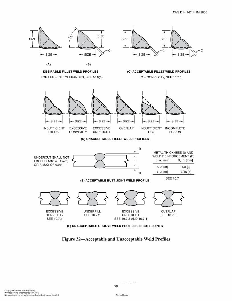
ßÉÍ ÜïìòïñÜïìòïÓæîððë
79
Figure 32�Acceptable and Unacceptable Weld Profiles
ݱ°§®·¹¸¬ ß³»®·½¿² É»´¼·²¹ ͱ½·»¬§ Ю±ª·¼»¼ ¾§ ×ØÍ «²¼»® ´·½»²» ©·¬¸ ßÉÍ
Ò±¬ º±® λ¿´»Ò± ®»°®±¼«½¬·±² ±® ²»¬©±®µ·²¹ °»®³·¬¬»¼ ©·¬¸±«¬ ´·½»²» º®±³ ×ØÍ
óóÀôôÀôôÀóÀóÀôôÀôôÀôÀôôÀóóó
ßÉÍ ÜïìòïñÜïìòïÓæîððë
80
ments of this specification, or as modified by mutualagreement between the Manufacturer and Owner.
For welds subject to nondestructive testing in accor-dance with 10.8, 10.11, 10.15, 10.16, or 10.17, the test-ing may begin immediately after the completed weldshave cooled to ambient temperature. However, nonde-structive testing of ASTM A 514, A 517, and A 709Grade 100 and 100W steels shall begin not less than48 hours after the completed welds have cooled to ambi-ent temperature.
Refer to ASTM E 1316, Standard Terminology forNondestructive Examinations, for standard definitions ofterms.
10.8.2 Welds that do not meet the nondestructiveexamination requirements of this specification shall berepaired by the methods permitted by Section 12, Repairand Correction of Defects.
10.8.3 Nondestructive examination in this specifica-tion is only intended to apply to primary welds, unlessotherwise specifically agreed to in the contract betweenthe Manufacturer and the Owner.
10.8.4 A weld that is to be subjected to nondestructiveexamination need not be ground or otherwise smoothed,provided surface irregularities or juncture with the basemetal do not obscure objectionable weld discontinuitiesduring examination.
10.9 Radiographic Examination of Welds
10.9.1 The procedures and standards set forth in thissection are to govern radiographic examination of weldswhen such testing is required by stipulation of 10.8.These procedures are restricted to inspection of groovewelds with complete joint penetration.
10.9.2 Variations in testing procedure, equipment,and acceptance standards from those given in this sectionmay be used upon agreement with the Owner. Such vari-ations include the radiographic examination of filletwelds, T-welds, or corner welds; changes in source-to-film distance; unusual geometries; unusual penetrameterapplication, film type, or densities; and film exposure ordevelopment variations.
10.9.3 Information furnished to the bidders shallclearly identify the extent of radiographic testingrequired.
10.9.4 Complete testing, when specified, requires thatthe entire length of weld in each designated joint shall betested.
10.9.5 Spot testing, when specified, requires that thenumber of spots to be radiographed in a stated length ofweld in each designated category of weld joint shall beincluded in information furnished to bidders. Each spot
radiograph shall show at least 4 in. [100 mm] of weldlength. If a spot radiograph shows discontinuities thatrequire repair, as defined in 10.11, two adjacent spotsshall be tested. If discontinuities requiring repair aredetected in either of these, the entire length of weld inthat joint shall be tested radiographically.
10.10 Radiographic Procedure
10.10.1 Radiographs shall be made by either X-ray orisotope radiation methods. Radiography shall be con-ducted in accordance with ASTM E 94, Standard Guidefor Radiographic Examination.
10.10.2 The radiographic sensitivity shall be judgedbased on penetrameters. Radiographic technique andequipment shall provide sufficient sensitivity to clearlydelineate the required penetrameters and the essentialholes as described in 10.10.4 and Table 19. Identifyingletters and numbers shall show clearly in the radiograph.Note: Alternative image quality indicators may be usedwhen approved by the Engineer.
10.10.3 Radiographs shall have an H & D density14 of2.0 minimum and 4.0 maximum. In addition, the densityin the area of interest shall not vary more than minus15% and plus 30% from the density through the penet-rameter.
10.10.4 One penetrameter, centered on the film, shallbe used for film 10 in. [250 mm] or less in length. Twopenetrameters, one centered and one at the end of thefilm, shall be used for radiographs with a film lengthgreater than 10 in. [250 mm] in length. For panoramicexposures, three penetrameters shall be placed 120° apartaround the object being radiographed. Penetrametersshall be placed on the source side whenever possible.Failure to prove adequate sensitivity on all threepenetrameters shall disqualify the exposure, and theentire technique shall be repeated.
10.10.5 Radiographs shall be made using a singlesource of radiation approximately centered with respectto the length and width of the area being examined. Theminimum source-to-object distance shall be the greaterof the film length or 7 times the maximum thickness ofthe weld being examined. For panoramic exposures, theminimum source-to-object distance shall be 7 times themaximum weld thickness. During exposure, the filmshall be as close as possible to the opposite side of theweld being examined. Edge blocks shall be used whenradiographing butt joints greater than 1/2 in. [13 mm]
14. H & D density, D, is a measure of film blackeningexpressed as D = log (Io/I), where:
Io = light intensity on the filmI = light transmitted through the film
ݱ°§®·¹¸¬ ß³»®·½¿² É»´¼·²¹ ͱ½·»¬§ Ю±ª·¼»¼ ¾§ ×ØÍ «²¼»® ´·½»²» ©·¬¸ ßÉÍ
Ò±¬ º±® λ¿´»Ò± ®»°®±¼«½¬·±² ±® ²»¬©±®µ·²¹ °»®³·¬¬»¼ ©·¬¸±«¬ ´·½»²» º®±³ ×ØÍ
óóÀôôÀôôÀóÀóÀôôÀôôÀôÀôôÀóóó
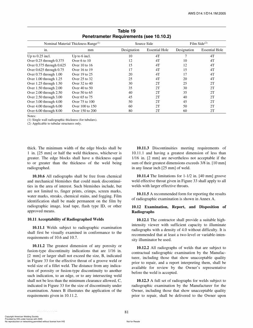
ßÉÍ ÜïìòïñÜïìòïÓæîððë
81
thick. The minimum width of the edge blocks shall be1 in. [25 mm] or half the weld thickness, whichever isgreater. The edge blocks shall have a thickness equalto or greater than the thickness of the weld beingradiographed.
10.10.6 All radiographs shall be free from chemicaland mechanical blemishes that could mask discontinui-ties in the area of interest. Such blemishes include, butare not limited to, finger prints, crimps, screen marks,water marks, streaks, chemical stains, and fogging. Filmidentification shall be made permanent on the film byradiographic image, lead tape, flash type ID, or otherapproved means.
10.11 Acceptability of Radiographed Welds
10.11.1 Welds subject to radiographic examinationshall first be visually examined in conformance to therequirements of 10.6 and 10.7.
10.11.2 The greatest dimension of any porosity orfusion-type discontinuity indications that are 1/16 in.[2 mm] or larger shall not exceed the size, B, indicatedin Figure 33 for the effective throat of a groove weld orweld size of a fillet weld. The distance from any indica-tion of porosity or fusion-type discontinuity to anothersuch indication, to an edge, or to any intersecting weldshall not be less than the minimum clearance allowed, C,indicated in Figure 33 for the size of discontinuity underexamination. Annex B illustrates the application of therequirements given in 10.11.2.
10.11.3 Discontinuities meeting requirements of10.11.1 and having a greatest dimension of less than1/16 in. [2 mm] are nevertheless not acceptable if thesum of their greatest dimensions exceeds 3/8 in. [10 mm]in any linear inch [25 mm] of weld.
10.11.4 The limitations for 1-1/2 in. [40 mm] grooveweld effective throat given in Figure 33 shall apply to allwelds with larger effective throats.
10.11.5 A recommended form for reporting the resultsof radiographic examination is shown in Annex A.
10.12 Examination, Report, and Disposition ofRadiographs
10.12.1 The contractor shall provide a suitable high-intensity viewer with sufficient capacity to illuminateradiographs with a density of 4.0 without difficulty. It isrecommended that at least a two-level or variable-inten-sity illuminator be used.
10.12.2 All radiographs of welds that are subject tocontractual radiographic examination by the Manufac-turer, including those that show unacceptable qualityprior to repair, and a report interpreting them, shall beavailable for review by the Owner�s representativebefore the weld is accepted.
10.12.3 A full set of radiographs for welds subject toradiographic examination by the Manufacturer for theOwner, including those that show unacceptable qualityprior to repair, shall be delivered to the Owner upon
Ì¿¾´» ïçл²»¬®¿³»¬»® λ¯«·®»³»²¬ ø»» ïðòïðòî÷
Nominal Material Thickness Range(1) Source Side Film Side(2)
in. mm Designation Essential Hole Designation Essential Hole
Up to 0.25 incl. Up to 6 incl. 10 4T 7 4TOver 0.25 through 0.375 Over 6 to 10 12 4T 10 4TOver 0.375 through 0.625 Over 10 to 16 15 4T 12 4TOver 0.625 through 0.75 Over 16 to 19 17 4T 15 4TOver 0.75 through 1.00 Over 19 to 25 20 4T 17 4TOver 1.00 through 1.25 Over 25 to 32 25 4T 20 4TOver 1.25 through 1.50 Over 32 to 40 30 2T 25 2TOver 1.50 through 2.00 Over 40 to 50 35 2T 30 2TOver 2.00 through 2.50 Over 50 to 65 40 2T 35 2TOver 2.50 through 3.00 Over 65 to 75 45 2T 40 2TOver 3.00 through 4.00 Over 75 to 100 50 2T 45 2TOver 4.00 through 6.00 Over 100 to 150 60 2T 50 2TOver 6.00 through 8.00 Over 150 to 200 80 2T 60 2TNotes:(1) Single wall radiographic thickness (for tubulars).(2) Applicable to tubular structures only.
ݱ°§®·¹¸¬ ß³»®·½¿² É»´¼·²¹ ͱ½·»¬§ Ю±ª·¼»¼ ¾§ ×ØÍ «²¼»® ´·½»²» ©·¬¸ ßÉÍ
Ò±¬ º±® λ¿´»Ò± ®»°®±¼«½¬·±² ±® ²»¬©±®µ·²¹ °»®³·¬¬»¼ ©·¬¸±«¬ ´·½»²» º®±³ ×ØÍ
óóÀôôÀôôÀóÀóÀôôÀôôÀôÀôôÀóóó
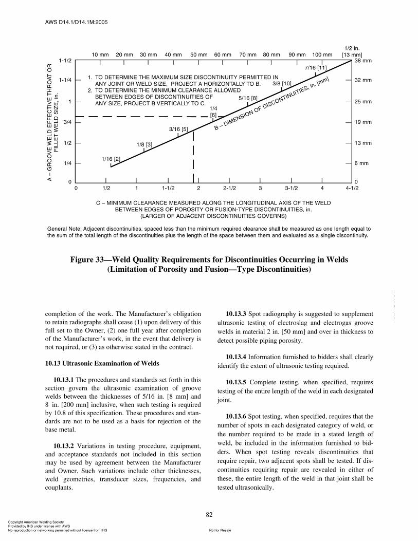
ßÉÍ ÜïìòïñÜïìòïÓæîððë
82
completion of the work. The Manufacturer�s obligationto retain radiographs shall cease (1) upon delivery of thisfull set to the Owner, (2) one full year after completionof the Manufacturer�s work, in the event that delivery isnot required, or (3) as otherwise stated in the contract.
10.13 Ultrasonic Examination of Welds
10.13.1 The procedures and standards set forth in thissection govern the ultrasonic examination of groovewelds between the thicknesses of 5/16 in. [8 mm] and8 in. [200 mm] inclusive, when such testing is requiredby 10.8 of this specification. These procedures and stan-dards are not to be used as a basis for rejection of thebase metal.
10.13.2 Variations in testing procedure, equipment,and acceptance standards not included in this sectionmay be used by agreement between the Manufacturerand Owner. Such variations include other thicknesses,weld geometries, transducer sizes, frequencies, andcouplants.
10.13.3 Spot radiography is suggested to supplementultrasonic testing of electroslag and electrogas groovewelds in material 2 in. [50 mm] and over in thickness todetect possible piping porosity.
10.13.4 Information furnished to bidders shall clearlyidentify the extent of ultrasonic testing required.
10.13.5 Complete testing, when specified, requirestesting of the entire length of the weld in each designatedjoint.
10.13.6 Spot testing, when specified, requires that thenumber of spots in each designated category of weld, orthe number required to be made in a stated length ofweld, be included in the information furnished to bid-ders. When spot testing reveals discontinuities thatrequire repair, two adjacent spots shall be tested. If dis-continuities requiring repair are revealed in either ofthese, the entire length of the weld in that joint shall betested ultrasonically.
Figure 33�Weld Quality Requirements for Discontinuities Occurring in Welds(Limitation of Porosity and Fusion�Type Discontinuities)
ݱ°§®·¹¸¬ ß³»®·½¿² É»´¼·²¹ ͱ½·»¬§ Ю±ª·¼»¼ ¾§ ×ØÍ «²¼»® ´·½»²» ©·¬¸ ßÉÍ
Ò±¬ º±® λ¿´»Ò± ®»°®±¼«½¬·±² ±® ²»¬©±®µ·²¹ °»®³·¬¬»¼ ©·¬¸±«¬ ´·½»²» º®±³ ×ØÍ
óóÀôôÀôôÀóÀóÀôôÀôôÀôÀôôÀóóó

ßÉÍ ÜïìòïñÜïìòïÓæîððë
83
10.14 Ultrasonic Testing Equipment and Calibration
10.14.1 The apparatus for ultrasonic examinationshall meet the requirements of ASTM E 164, Recom-mended Practice for Ultrasonic Contact Examination ofWeldments, and ASTM E 317, Recommended Practicesfor Evaluating Performance Characteristics of Pulse-Echo Ultrasonic Testing Systems. Refer to ASTME 1316, Standard Terminology for NondestructiveExaminations, for standard definitions of terms.
10.14.2 Test instruments shall include internal stabili-zation so that, after warm up, no variation in responsegreater than ±1 dB occurs with supply voltage changesof 15% nominal or, in the case of battery powered instru-ments, over the battery charge operating life. There shallbe an alarm or meter to signal a drop in battery voltageprior to instrument shutoff due to battery exhaustion.
10.14.3 The test instrument shall have a calibratedgain control (attenuator) adjustable in discrete 1 or 2 dBsteps over a range of at least 60 dB.
10.14.4 The dynamic range of the instrument�s dis-play shall be such that a difference of 1 dB of amplitudecan be easily detected.
10.14.5 Each search unit shall be marked to clearlyindicate the frequency of the transducer, nominal angleof refraction, and index point.
10.14.6 Preferred couplants are a cellulose gum-watermixture and glycerine with a wetting agent. Where possi-ble, avoid the use of oil or grease as the couplant forexamination of welds. If oil or grease is used as the cou-plant, the requirements of 7.2.1 shall be met before anyrepairs are made.
10.14.7 The horizontal linearity of the test instrumentshall be within ±5% over the linear range that includes90% of the sweep length presented on the display for thelongest sound path to be used. The horizontal linearityshall be measured by the techniques prescribed in Sec-tion 7.9 of ASTM E 317, except that the results may betabulated rather than graphically represented. Horizontallinearity shall be checked after each 40 hours of instru-ment use.
10.14.8 Internal reflections from the search unit, witha screen presentation higher than the horizontal referenceline, appearing on the screen to the right of the soundentry point shall not occur beyond 1/2 in. [13 mm] equiv-alent distance in steel when the sensitivity is as follows:20 dB more than that required to produce a maximizedhorizontal reference-line height indication from the1/16 in. [1.59 mm] diameter hole in the InternationalInstitute of Welding (IIW) reference block (see ASTME 164).
10.14.9 The dimensions of the search unit shall besuch that the minimal allowable distance, X, between thetoe of the search unit and the edge of the IIW block, shallbe as follows:
(1) 70° transducer, X = 2 in. [50 mm](2) 60° transducer, X = 1-7/16 in. [37 mm](3) 45° transducer, X = 1 in. [25 mm]The search unit shall be positioned for maximum indi-
cation from the 1/16 in. [1.59 mm] diameter hole in theIIW calibration block.
10.14.10 Resolution
10.14.10.1 For shear waves, the combination ofsearch unit and instrument shall resolve the appropriatethree holes in the resolution test block shown in Figures34A and 34B. For a 70° angle, the transducer should beset in position Q on the resolution block as shown in Fig-ure 34C. The resolution shall be evaluated with theinstrument controls set at normal test settings, and withindications from the holes brought to midscreen height.Resolution shall be sufficient to distinguish at least thepeaks of indications from the three holes.
10.14.10.2 To determine longitudinal wave resolu-tion, the instrument controls shall be at normal settingswith indications from the holes brought to midscreenheight (see Figure 34C).
(1) Set the transducer in position F on the IIW block.(2) Transducer and instrument should resolve all
three distances.
10.14.11 The IIW ultrasonic reference block, shownin ASTM E 164, shall be the standard used for both dis-tance and sensitivity calibration. More portable referenceblocks of other designs may be used, provided they meetthe requirements of this specification and are referencedback to the IIW block. Approved designs are shown inASTM E 164. See Figure 34C for application.
10.14.12 Using a corner reflector for calibration pur-poses is prohibited.
10.14.13 The gain control (attenuator) of the instru-ment shall meet the requirements of 10.14.3 and shall bechecked for correct calibration at two-month intervals inaccordance with a procedure approved by the manufac-turer of the instrument.
10.14.14 With the use of an approved calibrationblock, each angle-beam search unit shall be checkedafter each eight hours of use to determine that:
(1) The contact face is flat,(2) The sound entry point is correct, and(3) The beam angle is within the permitted ±2°
tolerance.Search units that do not meet these requirements shall
be corrected or replaced.
ݱ°§®·¹¸¬ ß³»®·½¿² É»´¼·²¹ ͱ½·»¬§ Ю±ª·¼»¼ ¾§ ×ØÍ «²¼»® ´·½»²» ©·¬¸ ßÉÍ
Ò±¬ º±® λ¿´»Ò± ®»°®±¼«½¬·±² ±® ²»¬©±®µ·²¹ °»®³·¬¬»¼ ©·¬¸±«¬ ´·½»²» º®±³ ×ØÍ
óóÀôôÀôôÀóÀóÀôôÀôôÀôÀôôÀóóó
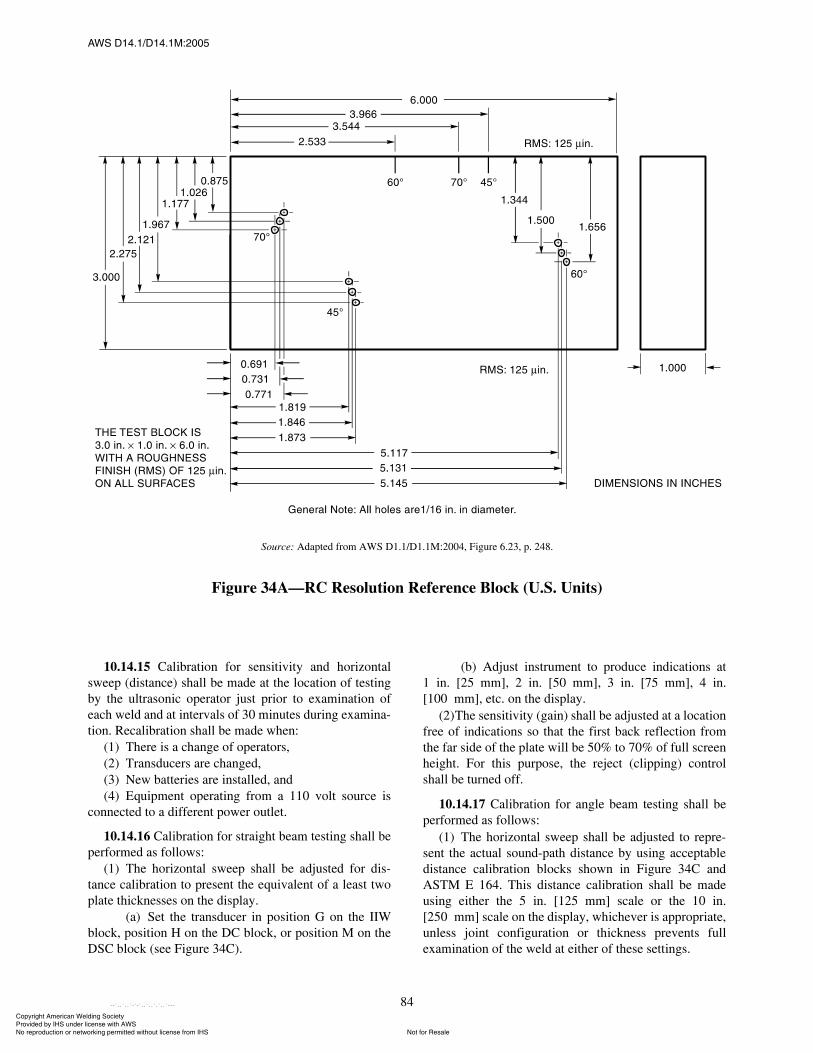
ßÉÍ ÜïìòïñÜïìòïÓæîððë
84
10.14.15 Calibration for sensitivity and horizontalsweep (distance) shall be made at the location of testingby the ultrasonic operator just prior to examination ofeach weld and at intervals of 30 minutes during examina-tion. Recalibration shall be made when:
(1) There is a change of operators,(2) Transducers are changed,(3) New batteries are installed, and(4) Equipment operating from a 110 volt source is
connected to a different power outlet.
10.14.16 Calibration for straight beam testing shall beperformed as follows:
(1) The horizontal sweep shall be adjusted for dis-tance calibration to present the equivalent of a least twoplate thicknesses on the display.
(a) Set the transducer in position G on the IIWblock, position H on the DC block, or position M on theDSC block (see Figure 34C).
(b) Adjust instrument to produce indications at1 in. [25 mm], 2 in. [50 mm], 3 in. [75 mm], 4 in.[100 mm], etc. on the display.
(2)The sensitivity (gain) shall be adjusted at a locationfree of indications so that the first back reflection fromthe far side of the plate will be 50% to 70% of full screenheight. For this purpose, the reject (clipping) controlshall be turned off.
10.14.17 Calibration for angle beam testing shall beperformed as follows:
(1) The horizontal sweep shall be adjusted to repre-sent the actual sound-path distance by using acceptabledistance calibration blocks shown in Figure 34C andASTM E 164. This distance calibration shall be madeusing either the 5 in. [125 mm] scale or the 10 in.[250 mm] scale on the display, whichever is appropriate,unless joint configuration or thickness prevents fullexamination of the weld at either of these settings.
Source: Adapted from AWS D1.1/D1.1M:2004, Figure 6.23, p. 248.
Figure 34A�RC Resolution Reference Block (U.S. Units)
ݱ°§®·¹¸¬ ß³»®·½¿² É»´¼·²¹ ͱ½·»¬§ Ю±ª·¼»¼ ¾§ ×ØÍ «²¼»® ´·½»²» ©·¬¸ ßÉÍ
Ò±¬ º±® λ¿´»Ò± ®»°®±¼«½¬·±² ±® ²»¬©±®µ·²¹ °»®³·¬¬»¼ ©·¬¸±«¬ ´·½»²» º®±³ ×ØÍ
óóÀôôÀôôÀóÀóÀôôÀôôÀôÀôôÀóóó
ßÉÍ ÜïìòïñÜïìòïÓæîððë
85
(a) Set the transducer in position D on the IIWblock (any angle).
(b) Adjust the instrument to obtain indications onthe display at 4 in. [100 mm] and 9 in. [225 mm] from aType 1 block, or at 4 in. [100 mm] and 8 in. [200 mm]from a Type 2 block.
(c) Set the transducer in position J or L on theDSC block (any angle).
(d) Adjust the instrument to obtain indicationson the display at 1 in. [25 mm], 5 in. [125 mm], 9 in.[225 mm] in the J position, or at 3 in. [75 mm], and 7 in.[175 mm] in the L position.
(e) Set the transducer in position I on the DCblock (any angle).
(f) Adjust the instrument to obtain indications onthe display at 1 in. [25 mm], 2 in. [50 mm], 3 in.[75 mm], 4 in. [100 mm], and so forth.
(2) With the unit adjusted to conform with therequirements of 10.14.1 through 10.14.10, the sensitivityshall be adjusted by the use of the gain control (attenua-tor) so that a horizontal reference-level trace deflectionresults on the display with the maximum indication fromthe 0.060 in. [1.59 mm] diameter hole in the IIW blockor from the equivalent reference reflector in other accept-able calibration blocks. This basic sensitivity thenbecomes the zero reference level for discontinuity evalu-ation and shall be recorded on the ultrasonic test reportsunder reference level. See Annex A for a sample ultra-sonic test report form.
(a) Set the transducer in position A on the IIWblock (any angle).
(b) Adjust the maximized signal from the 0.060in. [1.59 mm] hole to attain a horizontal reference-lineheight indication.
Source: Adapted from AWS D1.1/D1.1M:2004, Figure 6.23 (Continued), p. 249.
Figure 34B�RC Resolution Reference Block (SI Units)
ݱ°§®·¹¸¬ ß³»®·½¿² É»´¼·²¹ ͱ½·»¬§ Ю±ª·¼»¼ ¾§ ×ØÍ «²¼»® ´·½»²» ©·¬¸ ßÉÍ
Ò±¬ º±® λ¿´»Ò± ®»°®±¼«½¬·±² ±® ²»¬©±®µ·²¹ °»®³·¬¬»¼ ©·¬¸±«¬ ´·½»²» º®±³ ×ØÍ
óóÀôôÀôôÀóÀóÀôôÀôôÀôÀôôÀóóó
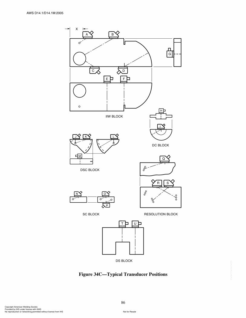
ßÉÍ ÜïìòïñÜïìòïÓæîððë
86
Figure 34C�Typical Transducer Positions
ݱ°§®·¹¸¬ ß³»®·½¿² É»´¼·²¹ ͱ½·»¬§ Ю±ª·¼»¼ ¾§ ×ØÍ «²¼»® ´·½»²» ©·¬¸ ßÉÍ
Ò±¬ º±® λ¿´»Ò± ®»°®±¼«½¬·±² ±® ²»¬©±®µ·²¹ °»®³·¬¬»¼ ©·¬¸±«¬ ´·½»²» º®±³ ×ØÍ
óóÀôôÀôôÀóÀóÀôôÀôôÀôÀôôÀóóó
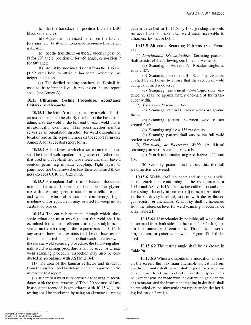
ßÉÍ ÜïìòïñÜïìòïÓæîððë
87
(c) Set the transducer in position L on the DSCblock (any angle).
(d) Adjust the maximized signal from the 1/32 in.[0.8 mm] slot to attain a horizontal reference-line heightindication.
(e) Set the transducer on the SC block in positionN for 70° angle, position O for 45° angle, or position Pfor 60° angle.
(f) Adjust the maximized signal from the 0.060 in.[1.59 mm] hole to attain a horizontal reference-lineheight indication.
(g) The decibel reading obtained in (f) shall beused as the reference level, b, reading on the test reportsheet (see Annex A).
10.15 Ultrasonic Testing Procedure, AcceptanceCriteria, and Reports
10.15.1 The letter Y accompanied by a weld identifi-cation number shall be clearly marked on the base metaladjacent to the weld at the left end of each weld that isultrasonically examined. This identification numberserves as an orientation direction for weld discontinuitylocation and as the report number on the report form (seeAnnex A for suggested report form).
10.15.2 All surfaces to which a search unit is appliedshall be free of weld spatter, dirt, grease, oil, (other thanthat used as a couplant) and loose scale and shall have acontour permitting intimate coupling. Tight layers ofpaint need not be removed unless their combined thick-ness exceeds 0.010 in. [0.25 mm].
10.15.3 A couplant shall be used between the searchunit and the metal. The couplant should be either glycer-ine with a wetting agent, if needed, or a cellulose gumand water mixture of a suitable consistency. Lightmachine oil, or equivalent, may be used for couplant oncalibration blocks.
10.15.4 The entire base metal through which ultra-sonic vibrations must travel to test the weld shall beexamined for laminar reflectors, using a straight-beamsearch unit conforming to the requirements of 10.14. Ifany area of base metal exhibits total loss of back reflec-tion and is located in a position that would interfere withthe normal weld scanning procedure, the following alter-nate weld scanning procedure shall be used. Alternateweld scanning procedure inspection may also be con-ducted in accordance with ASTM E 164.
(1) The area of the laminar reflector and its depthfrom the surface shall be determined and reported on theultrasonic test report.
(2) If part of a weld is inaccessible to testing in accor-dance with the requirements of Table 20 because of lam-inar content recorded in accordance with 10.15.4(1), thetesting shall be conducted by using an alternate scanning
pattern described in 10.15.5, by first grinding the weldsurfaces flush to make total weld areas accessible toultrasonic testing, or both.
10.15.5 Alternate Scanning Patterns (See Figure35)
(1) Longitudinal Discontinuities. Scanning patternsshall consist of the following combined movements:
(a) Scanning movement A�Rotation angle, a,equals 10°.
(b) Scanning movement B�Scanning distance,b, shall be sufficient to ensure that the section of weldbeing examined is covered.
(c) Scanning movement C�Progression dis-tance, c, shall be approximately one-half of the trans-ducer width.
(2) Transverse Discontinuities(a) Scanning pattern D�when welds are ground
flush.(b) Scanning pattern E�when weld is not
ground flush.(c) Scanning angle e = 15° maximum.(d) Scanning pattern shall ensure the full weld
section is covered.(3) Electroslag or Electrogas Welds. (Additional
scanning pattern)�scanning pattern E(a) Search unit rotation angle, e, between 45° and
60°.(b) Scanning pattern shall ensure that the full
weld section is covered.
10.15.6 Welds shall be examined using an angle-beam search unit conforming to the requirements of10.14 and ASTM E 164. Following calibration and dur-ing testing, the only instrument adjustment permitted isin the sensitivity-level adjustment with the calibratedgain control or attenuator. Sensitivity shall be increasedfrom the reference level for weld scanning in accordancewith Table 21.
10.15.6.1 If mechanically possible, all welds shallbe scanned from both sides on the same face for longitu-dinal and transverse discontinuities. The applicable scan-ning pattern, or patterns, shown in Figure 35 shall beused.
10.15.6.2 The testing angle shall be as shown inTable 20.
10.15.6.3 When a discontinuity indication appearson the screen, the maximum attainable indication fromthe discontinuity shall be adjusted to produce a horizon-tal reference level trace deflection on the display. Thisadjustment shall be made with the calibrated gain controlor attenuator, and the instrument reading in decibels shallbe recorded on the ultrasonic test report under the head-ing Indication Level, a.
ݱ°§®·¹¸¬ ß³»®·½¿² É»´¼·²¹ ͱ½·»¬§ Ю±ª·¼»¼ ¾§ ×ØÍ «²¼»® ´·½»²» ©·¬¸ ßÉÍ
Ò±¬ º±® λ¿´»Ò± ®»°®±¼«½¬·±² ±® ²»¬©±®µ·²¹ °»®³·¬¬»¼ ©·¬¸±«¬ ´·½»²» º®±³ ×ØÍ
óóÀôôÀôôÀóÀóÀôôÀôôÀôÀôôÀóóó
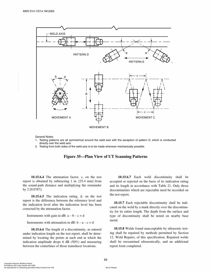
ßÉÍ ÜïìòïñÜïìòïÓæîððë
88
10.15.6.4 The attenuation factor, c, on the testreport is obtained by subtracting 1 in. [25.4 mm] fromthe sound-path distance and multiplying the remainderby 2 [0.0787].
10.15.6.5 The indication rating, d, on the testreport is the difference between the reference level andthe indication level after the indication level has beencorrected by the attenuation factor.
Instruments with gain in dB: a � b � c = d
Instruments with attenuation in dB: b � a � c = d
10.15.6.6 The length of a discontinuity, as enteredunder indication length on the test report, shall be deter-mined by locating the points at each end at which theindication amplitude drops 6 dB (50%) and measuringbetween the centerlines of those transducer locations.
10.15.6.7 Each weld discontinuity shall beaccepted or rejected on the basis of its indication ratingand its length in accordance with Table 21. Only thosediscontinuities which are rejectable need be recorded onthe test report.
10.15.7 Each rejectable discontinuity shall be indi-cated on the weld by a mark directly over the discontinu-ity for its entire length. The depth from the surface andtype of discontinuity shall be noted on nearby basemetal.
10.15.8 Welds found unacceptable by ultrasonic test-ing shall be repaired by methods permitted by Section12, Weld Repairs, of this specification. Repaired weldsshall be reexamined ultrasonically, and an additionalreport form completed.
Ù»²»®¿´ Ò±¬»æ
ïò Ì»¬·²¹ °¿¬¬»®² ¿®» ¿´´ §³³»¬®·½¿´ ¿®±«²¼ ¬¸» ©»´¼ ¿¨· ©·¬¸ ¬¸» »¨½»°¬·±² ±º °¿¬¬»®² Üô ©¸·½¸ · ½±²¼«½¬»¼¼·®»½¬´§ ±ª»® ¬¸» ©»´¼ ¿¨·ò
îò Ì»¬·²¹ º®±³ ¾±¬¸ ·¼» ±º ¬¸» ©»´¼ ¿¨· · ¬± ¾» ³¿¼» ©¸»®»ª»® ³»½¸¿²·½¿´´§ °±·¾´»ò
Figure 35�Plan View of UT Scanning Patterns
ݱ°§®·¹¸¬ ß³»®·½¿² É»´¼·²¹ ͱ½·»¬§ Ю±ª·¼»¼ ¾§ ×ØÍ «²¼»® ´·½»²» ©·¬¸ ßÉÍ
Ò±¬ º±® λ¿´»Ò± ®»°®±¼«½¬·±² ±® ²»¬©±®µ·²¹ °»®³·¬¬»¼ ©·¬¸±«¬ ´·½»²» º®±³ ×ØÍ
óóÀôôÀôôÀóÀóÀôôÀôôÀôÀôôÀóóó
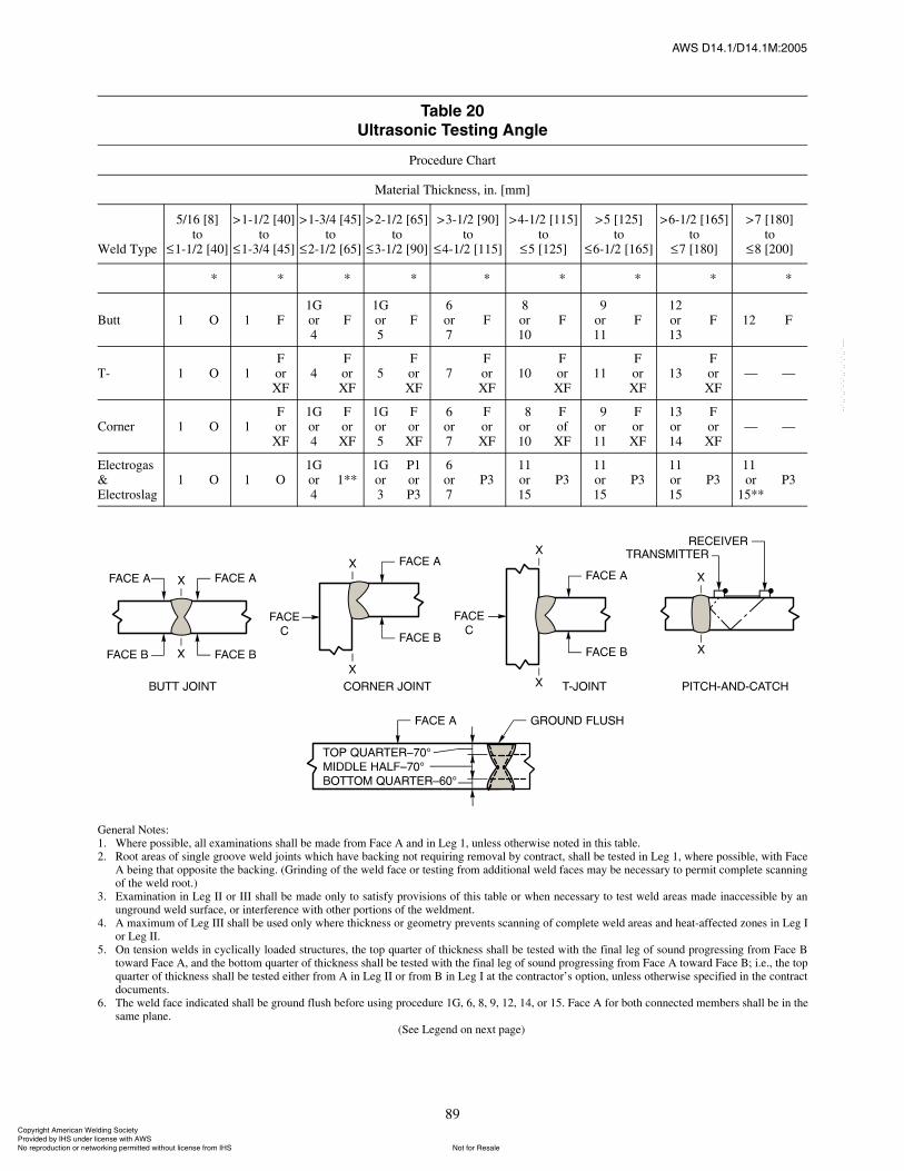
ßÉÍ ÜïìòïñÜïìòïÓæîððë
89
Ì¿¾´» îðË´¬®¿±²·½ Ì»¬·²¹ ß²¹´»
Procedure Chart
Material Thickness, in. [mm]
Weld Type
5/16 [8]to
1-1/2 [40]
>1-1/2 [40]to
1-3/4 [45]
>1-3/4 [45]to
2-1/2 [65]
>2-1/2 [65]to
3-1/2 [90]
>3-1/2 [90]to
4-1/2 [115]
>4-1/2 [115]to
5 [125]
>5 [125]to
6-1/2 [165]
>6-1/2 [165]to
7 [180]
>7 [180]to
8 [200]
* * * * * * * * *
Butt 1 O 1 F1Gor4
F1Gor5
F6or7
F8or10
F9
or11
F12or13
F 12i F
T- 1 O 1ForXF
4ForXF
5ForXF
7ForXF
10ForXF
11ForXF
13ForXF
� �
Corner 1 O 1ForXF
1Gor4
ForXF
1Gor5
ForXF
6or7
ForXF
8or10
FofXF
9or11
ForXF
13or14
ForXF
� �
Electrogas& Electroslag
1 O 1 O1Gor4
1**1Gor3
P1orP3
6or7
P311or15
P311or15
P311or15
P311ior
15**P3
General Notes:1. Where possible, all examinations shall be made from Face A and in Leg 1, unless otherwise noted in this table.2. Root areas of single groove weld joints which have backing not requiring removal by contract, shall be tested in Leg 1, where possible, with Face
A being that opposite the backing. (Grinding of the weld face or testing from additional weld faces may be necessary to permit complete scanningof the weld root.)
3. Examination in Leg II or III shall be made only to satisfy provisions of this table or when necessary to test weld areas made inaccessible by anunground weld surface, or interference with other portions of the weldment.
4. A maximum of Leg III shall be used only where thickness or geometry prevents scanning of complete weld areas and heat-affected zones in Leg Ior Leg II.
5. On tension welds in cyclically loaded structures, the top quarter of thickness shall be tested with the final leg of sound progressing from Face Btoward Face A, and the bottom quarter of thickness shall be tested with the final leg of sound progressing from Face A toward Face B; i.e., the topquarter of thickness shall be tested either from A in Leg II or from B in Leg I at the contractor�s option, unless otherwise specified in the contractdocuments.
6. The weld face indicated shall be ground flush before using procedure 1G, 6, 8, 9, 12, 14, or 15. Face A for both connected members shall be in thesame plane.
(See Legend on next page)
ݱ°§®·¹¸¬ ß³»®·½¿² É»´¼·²¹ ͱ½·»¬§ Ю±ª·¼»¼ ¾§ ×ØÍ «²¼»® ´·½»²» ©·¬¸ ßÉÍ
Ò±¬ º±® λ¿´»Ò± ®»°®±¼«½¬·±² ±® ²»¬©±®µ·²¹ °»®³·¬¬»¼ ©·¬¸±«¬ ´·½»²» º®±³ ×ØÍ
óóÀôôÀôôÀóÀóÀôôÀôôÀôÀôôÀóóó

ßÉÍ ÜïìòïñÜïìòïÓæîððë
90
Ì¿¾´» îð øݱ²¬·²«»¼÷Ë´¬®¿±²·½ Ì»¬·²¹ ß²¹´»
Legend:X �Check from Face �C.�G �Grind weld face flush.O �Not required.A Face� The face of the material from which the initial scanning is done (on T- and corner joints, follow above
sketches).B Face�Opposite the �A� face (same plate).C Face� The face opposite the weld on the connecting member or a T- or corner joint.* �Required only where reference level indication of discontinuity is noted in fusion zone (weld metal to
base metal interface) while searching at scanning level with primary procedures selected from firstcolumn.
** �Use 15 in. [375 mm] or 20 in. [500 mm] screen distance calibration.P � Pitch and catch shall be conducted for further discontinuity evaluation in only the middle half of the
material thickness with only 45° or 70° transducers of equal specification, both facing the weld. (Trans-ducers shall be held in a fixture to control positioning�see sketch.) Amplitude calibration for pitchand catch is normally made by calibrating a single search unit. When switching to dual search units forpitch and catch inspection, there should be assurance that this calibration does not change as a result ofinstrument variables.
F �Weld metal to base metal interface indications shall be further evaluated with either 70°, 60°, or 45°transducer�whichever sound path is nearest to being perpendicular to the suspected fusion surface.
Procedure Legend
Area of Weld Thickness
No.Top
QuarterMiddle
HalfBottomQuarter
1 70° 70° 70°
2 60° 60° 60°
3 45° 45° 45°
4 60° 70° 70°
5 45° 70° 70°
6 70°G A 70° 60°
7 60° B 70° 60°
8 70°G A 60° 60°
9 70°G A 60° 45°
10 60° B 60° 60°
11 45° B 70°** 45°
12 70°G A 45° 70°G B
13 45° B 45° 45°
14 70°G A 45° 45°
15 70°G A 70°A B 70°G B
ݱ°§®·¹¸¬ ß³»®·½¿² É»´¼·²¹ ͱ½·»¬§ Ю±ª·¼»¼ ¾§ ×ØÍ «²¼»® ´·½»²» ©·¬¸ ßÉÍ
Ò±¬ º±® λ¿´»Ò± ®»°®±¼«½¬·±² ±® ²»¬©±®µ·²¹ °»®³·¬¬»¼ ©·¬¸±«¬ ´·½»²» º®±³ ×ØÍ
óóÀôôÀôôÀóÀóÀôôÀôôÀôÀôôÀóóó

ßÉÍ ÜïìòïñÜïìòïÓæîððë
91
10.15.9 A report form which clearly identifies thework and the area of inspection shall be completed by theultrasonic inspector at the time of the inspection. Thereport form for welds that are unacceptable need onlycontain sufficient information to identify the weld, theinspector (signature), and the acceptability of the weld.An example of such a form is shown in Annex A.
10.15.10 All report forms pertaining to a weld subjectto contractual ultrasonic testing by the Manufacturer for
the Owner, including those that show unacceptable qual-ity prior to repair, shall be available for review by theOwner�s representative before the weld is accepted.
10.15.11 A full set of completed report forms ofwelds subject to contractual ultrasonic testing by theManufacturer for the Owner, including any that showunacceptable quality prior to repair, shall be delivered tothe Owner upon completion of the work. The Manufac-turer�s obligation to retain ultrasonic reports shall cease
Ì¿¾´» îïË´¬®¿±²·½ ß½½»°¬¿²½» ¿²¼ 붻½¬·±² Ý®·¬»®·¿
Weld Thickness,(1) in. [mm] and Search Unit Angle
Flaw Class
5/16 [8]to
3/4 [20]
> 3/4 [20]to
1-1/2 [40] > 1-1/2 [40] to 2-1/2 [65] > 2-1/2 [65] to 4 [100] > 4 [100] to 8 [200]
70° 70° 70° 60° 45° 70° 60° 45° 70° 60° 45°
Class A+10 & lower
+8 &lower
+4 & lower
+7 & lower
+9 & lower
+1 & lower
+4 & lower
+6 &lower
�2 & lower
+1 & lower
+3 & lower
Class B+11 +9 +5
+6+8+9
+10+11
+2+3
+5+6
+7+8
�1+0
+2+3
+4+5
Class C+12 +10 +7
+8+10+11
+12+13
+4+5
+7+8
+9+10
+1+2
+4+5
+6+7
Class D+13& up
+11& up
+9& up
+12& up
+14& up
+6& up
+9& up
+11& up
+3& up
+6& up
+8& up
Note:(1) Weld thickness shall be defined as the nominal thickness of the thinner of the two parts being joined.
General Notes:1. Class B and C flaws shall be separated by at least 2L, L being the length of the longer flaw, except that when two or more such flaws are not sepa-
rated by at least 2L, but the combined length of flaws and their separation distance is equal to or less than the maximum allowable length under theprovisions of Class B or C, the flaw shall be considered a single acceptable flaw.
2. Class B and C flaws shall not begin at a distance less than 2L from the end of the weld, L being the flaw length.3. Discontinuities detected at �scanning level� in the root face area of complete penetration double groove weld joints shall be evaluated using an
indicating rating 4 dB more sensitive than described in 10.15.6.5 when such welds are designated as �tension welds� on the drawing (subtract 4 dBfrom the indication rating �d�). This shall not apply if the weld joint is backgouged to sound metal to remove the root face, and magnetic particleexamination is used to verify that the root face has been removed.
Class A (Large Flaws)Any indication in this category shall be rejected (regardless of length).
Class B (Medium Flaws)Any indication in this category having a length greater than 3/4 in.[20 mm] shall be rejected.
Class C (Small Flaws)Any indication in this category having a length greater than 2 in.[50 mm] length in the middle half or 3/4 in. [20 mm] length in the topof bottom quarter of weld thickness shall be rejected.
Class D (Minor Flaws)Any indication in this category shall be accepted regardless of length orlocation in the weld.
Scanning Levels
Sound path,(2) in. [mm]Above Zero
Reference, dB
2-1/2 [65]>2-1/2 [65] to 5 [125]>5 [125] to 10 [250]>10 [250] to 15 [375]
20253545
Note: (2) refers to sound path distance; NOT material thickness.
ݱ°§®·¹¸¬ ß³»®·½¿² É»´¼·²¹ ͱ½·»¬§ Ю±ª·¼»¼ ¾§ ×ØÍ «²¼»® ´·½»²» ©·¬¸ ßÉÍ
Ò±¬ º±® λ¿´»Ò± ®»°®±¼«½¬·±² ±® ²»¬©±®µ·²¹ °»®³·¬¬»¼ ©·¬¸±«¬ ´·½»²» º®±³ ×ØÍ
óóÀôôÀôôÀóÀóÀôôÀôôÀôÀôôÀóóó
ßÉÍ ÜïìòïñÜïìòïÓæîððë
92
(1) upon delivery of this full set to the Owner or (2) at theend of one full year after completion of the Manufac-turer�s work, in the event that delivery is not required, oras otherwise provided in the contract.
10.16 Magnetic Particle Examination of Welds
10.16.1 The procedure and technique for magneticparticle examination, when required, shall be in accor-dance with ASTM E 709, Practice for Magnetic ParticleInspection (latest edition), and the standards of accep-tance shall be in accordance with 10.16.4.
10.16.2 Variations in testing procedure, equipment,and acceptance standards not included in this specifica-tion may be used upon agreement between the Manufac-turer and the Owner.
10.16.3 Welds subject to magnetic particle examina-tion shall first be subject to visual examination in accor-dance with the requirements of 10.6 and 10.7.
10.16.4 Welds that are subject to magnetic particleexamination shall be unacceptable if any discontinuitiesexceed the following limits:
(1) A magnetic particle indication of any porosity orfusion-type discontinuity, that is 1/16 in. [1.5 mm] orlarger in greatest dimension, shall not exceed the size, B,indicated in Figure 33 for the effective throat or weldsize involved. The distance from any indication of anacceptable porosity or fusion-type discontinuity toanother discontinuity, to an edge, or to any intersectingweld shall not be less than the minimum clearance, C,indicated by Figure 33 for the size of discontinuity underexamination. (Annex B illustrates the application of therequirements given. A sample report form is shown inAnnex A.)
(2) Discontinuities meeting the requirements of10.16.4(1) and having a greatest dimension of less than1/16 in. [1.5 mm] are nevertheless not acceptable if thesum of their greatest dimensions exceeds 3/8 in. [10 mm]in any linear inch [25 mm] of weld.
(3) The limitations given by Figure 33 for a grooveweld effective throat of 1-1/2 in. [40 mm] shall apply togroove welds of greater thickness.
10.17 Liquid Penetrant Examination of Welds
10.17.1 When liquid penetrant examination isrequired, the procedure and technique shall be in accor-dance with ASTM E 165, Recommended Practice forLiquid Penetrant Inspection. The standard of acceptanceshall be in accordance with 10.17.3.
10.17.2 Variations in testing procedure, equipment,and acceptance standards not included in this specifica-tion may be used upon agreement between the Manufac-turer and Owner.
10.17.3 Welds that are subject to liquid penetrantexamination shall be evaluated on the basis of therequirements for visual inspection as defined in 10.6 and10.7.
11. Field Weld Repair and Modification
11.1 General. Repairs and modifications shall requirethe approval of the Engineer (see 11.3.1). The materialcomposition of the components shall be identified andthe welding procedures approved by the Engineer beforestarting repair or modification. The repair and modifica-tion work shall conform to all applicable sections of thisspecification. When a modification includes removal,addition, or alteration of structural members, the Engi-neer shall verify that the original design requirements aresatisfied. This section is a guide to aid the Manufacturerand the Owner by suggesting pertinent items that shall beconsidered at the time of initial contract negotiations.The eventual need for field weld repairs as a result ofnormal wear and tear, modification, or accident is oftenforgotten. Every repair, no matter how small, becomesthe total responsibility of the Owner and the organizationperforming the repair work, who must consider its effecton the equipment involved. The original Manufacturershould be contacted to ensure that the projected repair isadvisable and sound from an engineering standpoint.Safe recommended repairs and modifications can only beaccomplished with knowledge of the design loading onthe equipment and the resulting stresses at the repairlocations.
Caution: Leaking of flammable liquids from pressur-ized lines may exist and shall be addressed to preventfires when welding and cutting is performed. Confinedspace circumstances can also exist on some repairoperations.
11.2 Field Repair�Manufacturer�s Responsibility.The Manufacturer shall furnish, as a part of instructionmanuals or as a separate publication, instructions forfield repair when required by the contract. The complete-ness and extent of material identification and weldingrepair procedures shall be covered in the contract.
11.2.1 Instructions by the Manufacturer shall includethe following:
(1) Qualification requirements of the welder perform-ing the repair (see Section 9, Qualification, for minimumrequirement).
(2) A list of materials used in the manufacture of theequipment and the location of materials by some appro-priate means such as an outline drawing. This shallinclude lists and locations of those materials that:
ݱ°§®·¹¸¬ ß³»®·½¿² É»´¼·²¹ ͱ½·»¬§ Ю±ª·¼»¼ ¾§ ×ØÍ «²¼»® ´·½»²» ©·¬¸ ßÉÍ
Ò±¬ º±® λ¿´»Ò± ®»°®±¼«½¬·±² ±® ²»¬©±®µ·²¹ °»®³·¬¬»¼ ©·¬¸±«¬ ´·½»²» º®±³ ×ØÍ
óóÀôôÀôôÀóÀóÀôôÀôôÀôÀôôÀóóó
ßÉÍ ÜïìòïñÜïìòïÓæîððë
93
(a) Are easily weldable without preheat orpostheat treatment, provided ambient temperatures areconsidered normal, and
(b) Require special welding procedures. For spe-cial welding procedures, the Manufacturer shall includeinformation concerning the base metals, filler metals,and preheat or postheat treatment so that properly quali-fied welders can make an acceptable weld repair.
11.2.2 All field weld repair procedures shall includerecommended means for inspection or testing of therepair by the Engineer or the equipment manufacturerand necessary nondestructive testing procedures.
11.2.3 The manufacturers should list special precau-tions for field welding of their products and other neces-sary precautions. The following items should beaddressed.
11.2.3.1 Field repair should not proceed:(1) Without adequate preparation (thorough cleaning
and joint preparation) and a full review of any previousrepairs in the area involved;
(2) Until the welder and weld repair area are ade-quately protected from the elements, and a proper equip-ment environment is provided; or
(3) Without considering the stresses on the members.
11.2.3.2 A method by which stresses can berelieved before welding, as well as the sequence ofrepair, should be considered.
11.2.3.3 The Manufacturer shall indicate weld-ments and components on which field repairs are notrecommended.
11.2.4 Safety precautions and good workmanshipinstructions listed in the various ANSI and AWS specifi-cations shall be followed, including, but not limitedto ANSI Z49.1, Safety in Welding, Cutting, and AlliedProcesses.
11.3 Field Repair�Owner�s Responsibility
11.3.1 The Owner shall appoint the Engineer whoshall be responsible for the actual field execution of therepair work, and the complete detailed adherence to therepair procedures furnished by the Manufacturer.
11.3.2 Owners or their agents shall permit only quali-fied and properly trained personnel to perform field weldrepairs, such as welders qualified in accordance with thisspecification.
11.3.3 Full and complete records of all repaired weldsshall be maintained by means of marked outline draw-ings or other appropriate documents.
12. Repair and Correction of Defects12.1 Weld Repairs
12.1.1 Overlap or Excessive Convexity. Excessweld metal shall be removed.
12.1.2 Excessive Concavity of Weld or Crater andUndersize Welds. Prepare surfaces and deposit addi-tional weld metal. All slag shall be removed and theadjacent base metal shall be clean before additionalwelding.
12.1.3 Cracks in Weld or Base Metal. Determine theextent of the crack by liquid penetrant, magnetic particleexamination, or other suitable means. Remove the crackand adjacent sound metal for a 2 in. [50 mm] lengthbeyond each end of the crack.
Prior to rewelding, these areas shall be checked by anappropriate inspection method, such as magnetic particleor liquid penetrant, to ensure complete removal ofcracked material. After rewelding in conformance to anapproved repair welding procedure, the repaired area(s)shall be reinspected per Section 10.
12.1.4 Undercutting. Undercutting may be repairedby grinding and blending or by welding. It is preferablydone by careful grinding and blending. Grinding shouldbe performed with a pencil-type grinder. The grindingmarks should be transverse to the length of the weld, andhave a 250 I 10�6 in. [6 I 10�6 m] finish or better. Blend-ing shall be done with a slope not to exceed 1 in 3. Onplates of 1/2 in. [13 mm] thickness and above, up to 7%reduction of base-material thickness is permitted. Repairof undercut areas by grinding and blending in excess ofthis amount may be permitted with the approval of theDesign Engineer. When undercut is to be repaired bywelding, the surfaces should be prepared and then addi-tional weld metal deposited.
12.1.5 Weld areas containing unacceptable incom-plete fusion, porosity or slag inclusions shall be removed(see 12.3) and rewelded.
12.2 Base Metal Repairs
12.2.1 Defects in Edges of Plate. If a defect is foundin a plate edge that exceeds the limits imposed in Table7, it shall be removed and repaired in accordance with7.3.
12.2.2 Arc Strikes and Temporary AttachmentAreas. Arc strikes or severed temporary welds shall beground smooth to ensure that no abrupt change in sectionexists. The smoothed area shall be inspected by anappropriate nondestructive testing method to ensure thatthere are no existing cracks or similar discontinuities.The Engineer may require hardness testing of the area to
ݱ°§®·¹¸¬ ß³»®·½¿² É»´¼·²¹ ͱ½·»¬§ Ю±ª·¼»¼ ¾§ ×ØÍ «²¼»® ´·½»²» ©·¬¸ ßÉÍ
Ò±¬ º±® λ¿´»Ò± ®»°®±¼«½¬·±² ±® ²»¬©±®µ·²¹ °»®³·¬¬»¼ ©·¬¸±«¬ ´·½»²» º®±³ ×ØÍ
óóÀôôÀôôÀóÀóÀôôÀôôÀôÀôôÀóóó
ßÉÍ ÜïìòïñÜïìòïÓæîððë
94
verify material properties. Any cracks or similar discon-tinuities shall be repaired in accordance with 12.1.3.
12.3 Removal of Defective Areas. The removal of weldmetal or portions of the base metal may be done bymachining, grinding, chipping, oxygen gouging, or aircarbon arc gouging. It shall be done in such a mannerthat the remaining weld metal is not nicked or undercut.Oxygen gouging shall not be used on quenched and tem-pered steel. Unacceptable portions of the weld shall beremoved without substantial removal of the base metal.Additional weld metal, to compensate for any deficiencyin size, shall be deposited using low-hydrogen elec-trodes, preferably smaller in diameter than those used formaking the original weld, and preferably not more than5/32 in. [4 mm] in diameter. The surfaces shall becleaned thoroughly before welding. Defects that occur inmaterial handling that do not affect the structural integ-rity of the design can be repaired by grinding.
12.4 Distortion and Camber. Members distorted bywelding may be straightened by mechanical means or bycarefully supervised application of a limited amount oflocalized heat. The temperature of heated areas, as mea-
sured by approved methods, shall be limited to thatimposed by the materials exposed to the heat, but it shallnot exceed 1100°F [590°C] for quenched and temperedor normalized and tempered steels, nor 1200°F [650°C]for other steels. The part to be heated for straighteningshall be substantially free of stress and external forces,except those stresses resulting from the mechanicalstraightening method used in conjunction with the appli-cation of heat. All heat-straightening operations shall becovered by an approved written procedure (see 7.2.4).
12.5 Correction of Improperly Fitted and WeldedMembers. If a weld is found to be unacceptable afteradditional work has rendered it inaccessible, or new con-ditions make correction of the unacceptable weld danger-ous or ineffectual, the original conditions shall berestored by removing welds or members, or both, beforethe corrections are made. If this is not done, the defi-ciency shall be compensated for by additional work per-formed according to an approved revised design.Improperly fitted and welded members require DesignEngineer approval prior to cutting apart. Cutting is to behandled by methods similar to those in 12.3.
ݱ°§®·¹¸¬ ß³»®·½¿² É»´¼·²¹ ͱ½·»¬§ Ю±ª·¼»¼ ¾§ ×ØÍ «²¼»® ´·½»²» ©·¬¸ ßÉÍ
Ò±¬ º±® λ¿´»Ò± ®»°®±¼«½¬·±² ±® ²»¬©±®µ·²¹ °»®³·¬¬»¼ ©·¬¸±«¬ ´·½»²» º®±³ ×ØÍ
óóÀôôÀôôÀóÀóÀôôÀôôÀôÀôôÀóóó
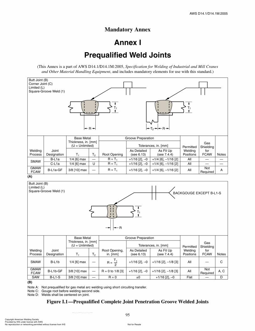
ßÉÍ ÜïìòïñÜïìòïÓæîððë
95
øß÷
øÞ÷
Ò±¬» ßæ Ò±¬ °®»¯«¿´·º·»¼ º±® ¹¿ ³»¬¿´ ¿®½ ©»´¼·²¹ «·²¹ ¸±®¬ ½·®½«·¬·²¹ ¬®¿²º»®òÒ±¬» Ýæ Ù±«¹» ®±±¬ ¾»º±®» ©»´¼·²¹ »½±²¼ ·¼»òÒ±¬» Üæ É»´¼ ¸¿´´ ¾» ½»²¬»®»¼ ±² ¶±·²¬ò
Figure I.1�Prequalified Complete Joint Penetration Groove Welded Joints
Þ«¬¬ Ö±·²¬ øÞ÷ݱ®²»® Ö±·²¬ øÝ÷Ô·³·¬»¼ øÔ÷ͯ«¿®»óÙ®±±ª» É»´¼ øï÷
É»´¼·²¹ Ю±½»
Ö±·²¬ Ü»·¹²¿¬·±²
Þ¿» Ó»¬¿´ ̸·½µ²»ô ·²ò ų³Ã
øË ã ˲´·³·¬»¼÷
Ù®±±ª» Ю»°¿®¿¬·±²
л®³·¬¬»¼ É»´¼·²¹ б·¬·±²
Ù¿ ͸·»´¼·²¹
º±® ÚÝßÉ Ò±¬»Î±±¬ Ñ°»²·²¹
̱´»®¿²½»ô ·²ò ų³Ã
Ìï Ìî
ß Ü»¬¿·´»¼ø»» êòïí÷
ß Ú·¬ Ë°ø»» éòìòì÷
ÍÓßÉÞóÔï¿ ïñì Åêà ³¿¨ � Î ã Ìï õïñïê ÅîÃô �ð õïñì ÅêÃô �ïñïê Åîà ߴ´ � �
ÝóÔï¿ ïñì Åêà ³¿¨ Ë Î ã Ìï õïñïê ÅîÃô �ð õïñì ÅêÃô �ïñïê Åîà ߴ´ � �
ÙÓßÉÚÝßÉ
ÞóÔï¿óÙÚ íñè Åïðà ³¿¨ � Î ã Ìï õïñïê ÅîÃô �ð õïñì ÅêÃô �ïñïê Åîà ߴ´Ò±¬
λ¯«·®»¼ß
Þ«¬¬ Ö±·²¬ øÞ÷Ô·³·¬»¼ øÔ÷ͯ«¿®»óÙ®±±ª» É»´¼ øï÷
É»´¼·²¹ Ю±½»
Ö±·²¬ Ü»·¹²¿¬·±²
Þ¿» Ó»¬¿´ ̸·½µ²»ô ·²ò ų³Ã
øË ã ˲´·³·¬»¼÷
Ù®±±ª» Ю»°¿®¿¬·±²
л®³·¬¬»¼ É»´¼·²¹ б·¬·±²
Ù¿ ͸·»´¼·²¹
º±® ÚÝßÉ Ò±¬»
ᱬ Ñ°»²·²¹ô ·²ò ų³Ã
̱´»®¿²½»ô ·²ò ų³Ã
Ìï Ìî
ß Ü»¬¿·´»¼ø»» êòïí÷
ß Ú·¬ Ë°ø»» éòìòì÷
ÍÓßÉ ÞóÔï¾ ïñì Åêà ³¿¨ � Î ã õïñïê ÅîÃô �ð õïñïê ÅîÃô �ïñè Åíà ߴ´ � Ý
ÙÓßÉÚÝßÉ
ÞóÔï¾óÙÚ íñè Åïðà ³¿¨ � Î ã 𠬱 ïñè Åíà õïñïê ÅîÃô �ð õïñïê ÅîÃô �ïñè Åíà ߴ´Ò±¬
λ¯«·®»¼ßô Ý
ÍßÉ ÞóÔïóÍ íñè Åïðà ³¿¨ � Î ã ð oð õïñïê ÅîÃô �ð Ú´¿¬ � Ü
Ìï
îóóóóóó
ß²²»¨ ×
Ю»¯«¿´·º·»¼ É»´¼ Ö±·²¬
(This Annex is a part of AWS D14.1/D14.1M:2005, Specification for Welding of Industrial and Mill Cranesand Other Material Handling Equipment, and includes mandatory elements for use with this standard.)
Mandatory Annex
ݱ°§®·¹¸¬ ß³»®·½¿² É»´¼·²¹ ͱ½·»¬§ Ю±ª·¼»¼ ¾§ ×ØÍ «²¼»® ´·½»²» ©·¬¸ ßÉÍ
Ò±¬ º±® λ¿´»Ò± ®»°®±¼«½¬·±² ±® ²»¬©±®µ·²¹ °»®³·¬¬»¼ ©·¬¸±«¬ ´·½»²» º®±³ ×ØÍ
óóÀôôÀôôÀóÀóÀôôÀôôÀôÀôôÀóóó
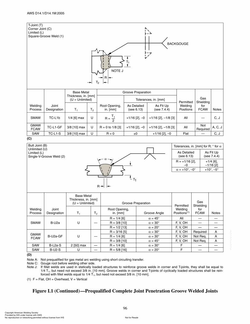
ßÉÍ ÜïìòïñÜïìòïÓæîððë
96
øÝ÷
øÜ÷
Ò±¬» ßæ Ò±¬ °®»¯«¿´·º·»¼ º±® ¹¿ ³»¬¿´ ¿®½ ©»´¼·²¹ «·²¹ ¸±®¬ ½·®½«·¬·²¹ ¬®¿²º»®òÒ±¬» Ýæ Ù±«¹» ®±±¬ ¾»º±®» ©»´¼·²¹ ±¬¸»® ·¼»òÒ±¬» Öæ ׺ º·´´»¬ ©»´¼ ¿®» «»¼ ·² ¬¿¬·½¿´´§ ´±¿¼»¼ ¬®«½¬«®» ¬± ®»·²º±®½» ¹®±±ª» ©»´¼ ·² ½±®²»® ¿²¼ Ì󶱷²¬ô ¬¸»§ ¸¿´´ ¾» »¯«¿´ ¬±
ïñì Ìïô ¾«¬ ²»»¼ ²±¬ »¨½»»¼ íñè ·²ò Åïð ³³Ãò Ù®±±ª» ©»´¼ ·² ½±®²»® ¿²¼ Ì󶱷²¬ ±º ½§½´·½¿´´§ ´±¿¼»¼ ¬®«½¬«®» ¸¿´´ ¾» ®»·²óº±®½»¼ ©·¬¸ º·´´»¬ ©»´¼ »¯«¿´ ¬± ïñì Ìïô ¾«¬ ²»»¼ ²±¬ »¨½»»¼ íñè ·²ò Åïð ³³Ãò
øï÷ Ú ã Ú´¿¬ô ÑØ ã Ѫ»®¸»¿¼ô Ê ã Ê»®¬·½¿´
Figure I.1 (Continued)�Prequalified Complete Joint Penetration Groove Welded Joints
ÌóÖ±·²¬ øÌ÷ݱ®²»® Ö±·²¬ øÝ÷Ô·³·¬»¼ øÔ÷ͯ«¿®»óÙ®±±ª» É»´¼ øï÷
É»´¼·²¹ Ю±½»
Ö±·²¬ Ü»·¹²¿¬·±²
Þ¿» Ó»¬¿´ ̸·½µ²»ô ·²ò ų³Ã
øË ã ˲´·³·¬»¼÷
Ù®±±ª» Ю»°¿®¿¬·±²
л®³·¬¬»¼ É»´¼·²¹ б·¬·±²
Ù¿ ͸·»´¼·²¹
º±® ÚÝßÉ Ò±¬»
ᱬ Ñ°»²·²¹ô ·²ò ų³Ã
̱´»®¿²½»ô ·²ò ų³Ã
Ìï Ìî
ß Ü»¬¿·´»¼ø»» êòïí÷
ß Ú·¬ Ë°ø»» éòìòì÷
ÍÓßÉ ÌÝóÔï¾ ïñì Åêà ³¿¨ Ë Î ã õïñïê ÅîÃô �ð õïñïê ÅîÃô �ïñè Åíà ߴ´ � Ýô Ö
ÙÓßÉÚÝßÉ
ÌÝóÔïóÙÚ íñè Åïðà ³¿¨ Ë Î ã 𠬱 ïñè Åíà õïñïê ÅîÃô �ð õïñïê ÅîÃô �ïñè Åíà ߴ´Ò±¬
λ¯«·®»¼ßô Ýô Ö
ÍßÉ ÌÝóÔïóÍ íñè Åïðà ³¿¨ Ë Î ã ð oð õïñïê ÅîÃô �ð Ú´¿¬ � Ýô Ö
Þ«¬¬ Ö±·²¬ øÞ÷˲´·³·¬»¼ øË÷Ô·³·¬»¼ øÔ÷Í·²¹´»óÊóÙ®±±ª» É»´¼ øî÷
̱´»®¿²½»ô ·²ò ų³Ã º±® Îå p º±®
ß Ü»¬¿·´»¼ø»» êòïí÷
ß Ú·¬ Ë°ø»» éòìòì÷
Î ã õïñïê ÅîÃô�ð
õïñì ÅêÃô�ïñïê ÅîÃ
ã õïðpô �ðp õïðpô �ëp
É»´¼·²¹ Ю±½»
Ö±·²¬ Ü»·¹²¿¬·±²
Þ¿» Ó»¬¿´ ̸·½µ²»ô ·²ò ų³Ã
øË ã ˲´·³·¬»¼÷ Ù®±±ª» Ю»°¿®¿¬·±²Ð»®³·¬¬»¼ É»´¼·²¹
б·¬·±²øï÷
Ù¿ ͸·»´¼·²¹
º±®ÚÝßÉ Ò±¬»Ìï Ìî
ᱬ Ñ°»²·²¹ô·²ò ų³Ã Ù®±±ª» ß²¹´»
ÍÓßÉ ÞóËî¿ Ë �
Î ã ïñì Åêà ã ìëp ß´´ � �
Î ã íñè Åïðà ã íðp Úô Êô ÑØ � �
Î ã ïñî Åïíà ã îðp Úô Êô ÑØ � �
ÙÓßÉÚÝßÉ
ÞóËî¿óÙÚ Ë �
Î ã íñïê Åëà ã íðp Úô Êô ÑØ Î»¯«·®»¼ ß
Î ã ïñì Åêà ã íðp Úô Êô ÑØ Ò±¬ λ¯ò ß
Î ã íñè Åïðà ã ìëp Úô Êô ÑØ Ò±¬ λ¯ò ß
ÍßÉ ÞóÔî¿óÍ î Åëðà ³¿¨ � Î ã ïñì Åêà ã íðp Ú � �
ÍßÉ ÞóËîóÍ Ë � Î ã ëñè Åïêà ã îðp Ú � �
Ìï
îóóóóóó
ݱ°§®·¹¸¬ ß³»®·½¿² É»´¼·²¹ ͱ½·»¬§ Ю±ª·¼»¼ ¾§ ×ØÍ «²¼»® ´·½»²» ©·¬¸ ßÉÍ
Ò±¬ º±® λ¿´»Ò± ®»°®±¼«½¬·±² ±® ²»¬©±®µ·²¹ °»®³·¬¬»¼ ©·¬¸±«¬ ´·½»²» º®±³ ×ØÍ
óóÀôôÀôôÀóÀóÀôôÀôôÀôÀôôÀóóó
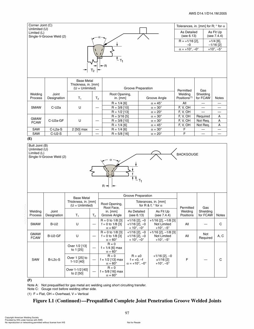
ßÉÍ ÜïìòïñÜïìòïÓæîððë
97
øÛ÷
øÚ÷
Ò±¬» ßæ Ò±¬ °®»¯«¿´·º·»¼ º±® ¹¿ ³»¬¿´ ¿®½ ©»´¼·²¹ «·²¹ ¸±®¬ ½·®½«·¬·²¹ ¬®¿²º»®òÒ±¬» Ýæ Ù±«¹» ®±±¬ ¾»º±®» ©»´¼·²¹ ±¬¸»® ·¼»ò
øï÷ Ú ã Ú´¿¬ô ÑØ ã Ѫ»®¸»¿¼ô Ê ã Ê»®¬·½¿´
Figure I.1 (Continued)�Prequalified Complete Joint Penetration Groove Welded Joints
ݱ®²»® Ö±·²¬ øÝ÷˲´·³·¬»¼ øË÷Ô·³·¬»¼ øÔ÷Í·²¹´»óÊóÙ®±±ª» É»´¼ øî÷
̱´»®¿²½»ô ·²ò ų³Ã º±® Îå p º±®
ß Ü»¬¿·´»¼ø»» êòïí÷
ß Ú·¬ Ë°ø»» éòìòì÷
Î ã õïñïê ÅîÃô�ð
õïñì ÅêÃô�ïñïê ÅîÃ
ã õïðpô �ðp õïðpô �ëp
É»´¼·²¹ Ю±½»
Ö±·²¬ Ü»·¹²¿¬·±²
Þ¿» Ó»¬¿´ ̸·½µ²»ô ·²ò ų³Ã
øË ã ˲´·³·¬»¼÷ Ù®±±ª» Ю»°¿®¿¬·±²Ð»®³·¬¬»¼ É»´¼·²¹
б·¬·±²øï÷
Ù¿ ͸·»´¼·²¹ º±® ÚÝßÉ Ò±¬»Ìï Ìî
ᱬ Ñ°»²·²¹ô·²ò ų³Ã Ù®±±ª» ß²¹´»
ÍÓßÉ ÝóËî¿ Ë �
Î ã ïñì Åêà ã ìëp ß´´ � �
Î ã íñè Åïðà ã íðp Úô Êô ÑØ � �
Î ã ïñî Åïíà ã îðp Úô Êô ÑØ � �
ÙÓßÉÚÝßÉ
ÝóËî¿óÙÚ Ë �
Î ã íñïê Åëà ã íðp Úô Êô ÑØ Î»¯«·®»¼ ß
Î ã íñè Åïðà ã íðp Úô Êô ÑØ Ò±¬ λ¯ò ß
Î ã ïñì Åêà ã ìëp Úô Êô ÑØ Ò±¬ λ¯ò ß
ÍßÉ ÝóÔî¿óÍ î Åëðà ³¿¨ � Î ã ïñì Åêà ã íðp Ú � �
ÍßÉ ÝóËîóÍ Ë � Î ã ëñè Åïêà ã îðp Ú � �
Þ«¬¬ Ö±·²¬ øÞ÷˲´·³·¬»¼ øË÷Ô·³·¬»¼ øÔ÷Í·²¹´»óÊóÙ®±±ª» É»´¼ øî÷
É»´¼·²¹ Ю±½»
Ö±·²¬ Ü»·¹²¿¬·±²
Þ¿» Ó»¬¿´ ̸·½µ²»ô ·²ò ų³Ã
øË ã ˲´·³·¬»¼÷
Ù®±±ª» Ю»°¿®¿¬·±²
л®³·¬¬»¼ É»´¼·²¹ б·¬·±²
Ù¿ ͸·»´¼·²¹ º±® ÚÝßÉ Ò±¬»
ᱬ Ñ°»²·²¹ô ᱬ Ú¿½»ô
·²ò ų³ÃÙ®±±ª» ß²¹´»
̱´»®¿²½»ô ·²ò ų³Ãº±® Î ú ºå p º±®
Ìï Ìî
ß Ü»¬¿·´»¼ø»» êòïí÷
ß Ú·¬ Ë°ø»» éòìòì÷
ÍÓßÉ ÞóËî Ë �Î ã 𠬱 ïñè Åíú ã 𠬱 ïñè ÅíÃ
ã êðp
õïñïê ÅîÃô �ðõïñïê ÅîÃô �ð
õ ïðpô �ðp
õïñïê ÅîÃô �ïñè ÅíÃÒ±¬ Ô·³·¬»¼õïðpô �ëp
ß´´ � Ý
ÙÓßÉÚÝßÉ
ÞóËîóÙÚ Ë �Î ã 𠬱 ïñè Åíú ã 𠬱 ïñè ÅíÃ
ã êðp
õïñïê ÅîÃô �ðõïñïê ÅîÃô �ð
õ ïðpô �ðp
õïñïê ÅîÃô �ïñè ÅíÃÒ±¬ Ô·³·¬»¼õïðpô �ëp
ß´´Ò±¬
λ¯«·®»¼ßô Ý
ÍßÉ ÞóÔî½óÍ
Ѫ»® ïñî Åïíà ¬± ï ÅîëÃ
�Î ã ð
º ã ïñì Åêà ³¿¨ã êðp
Î ã oðº ã õðô �º
ã õïðpô �ðp
õïñïê ÅîÃô �ðoïñïê ÅîÃõïðpô �ëp
Ú � ÝѪ»® ï Åîëà ¬±
ïóïñî ÅìðÃ�
Î ã ðº ã ïñî Åïíà ³¿¨
ã êðp
Ѫ»® ïóïñî Åìðà ¬± î ÅëðÃ
�Î ã ð
º ã ëñè Åïêà ³¿¨ã êðp
ݱ°§®·¹¸¬ ß³»®·½¿² É»´¼·²¹ ͱ½·»¬§ Ю±ª·¼»¼ ¾§ ×ØÍ «²¼»® ´·½»²» ©·¬¸ ßÉÍ
Ò±¬ º±® λ¿´»Ò± ®»°®±¼«½¬·±² ±® ²»¬©±®µ·²¹ °»®³·¬¬»¼ ©·¬¸±«¬ ´·½»²» º®±³ ×ØÍ
óóÀôôÀôôÀóÀóÀôôÀôôÀôÀôôÀóóó
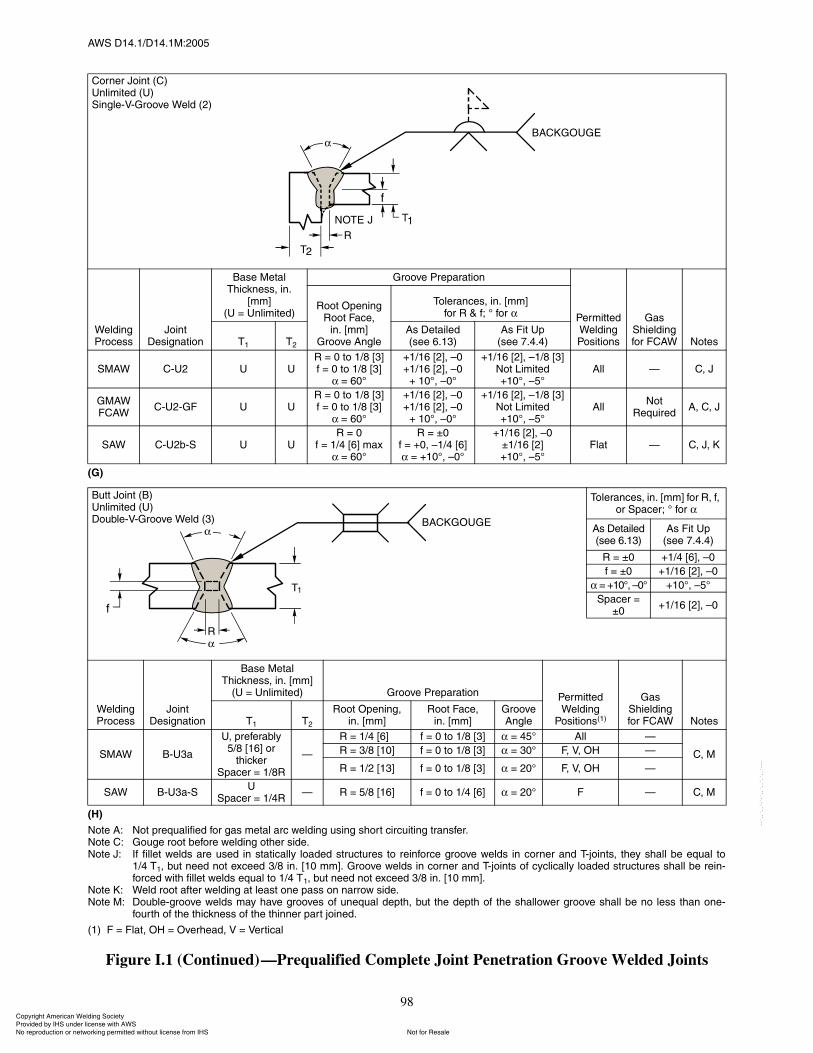
ßÉÍ ÜïìòïñÜïìòïÓæîððë
98
øÙ÷
øØ÷
Ò±¬» ßæ Ò±¬ °®»¯«¿´·º·»¼ º±® ¹¿ ³»¬¿´ ¿®½ ©»´¼·²¹ «·²¹ ¸±®¬ ½·®½«·¬·²¹ ¬®¿²º»®òÒ±¬» Ýæ Ù±«¹» ®±±¬ ¾»º±®» ©»´¼·²¹ ±¬¸»® ·¼»òÒ±¬» Öæ ׺ º·´´»¬ ©»´¼ ¿®» «»¼ ·² ¬¿¬·½¿´´§ ´±¿¼»¼ ¬®«½¬«®» ¬± ®»·²º±®½» ¹®±±ª» ©»´¼ ·² ½±®²»® ¿²¼ Ì󶱷²¬ô ¬¸»§ ¸¿´´ ¾» »¯«¿´ ¬±
ïñì Ìïô ¾«¬ ²»»¼ ²±¬ »¨½»»¼ íñè ·²ò Åïð ³³Ãò Ù®±±ª» ©»´¼ ·² ½±®²»® ¿²¼ Ì󶱷²¬ ±º ½§½´·½¿´´§ ´±¿¼»¼ ¬®«½¬«®» ¸¿´´ ¾» ®»·²óº±®½»¼ ©·¬¸ º·´´»¬ ©»´¼ »¯«¿´ ¬± ïñì Ìïô ¾«¬ ²»»¼ ²±¬ »¨½»»¼ íñè ·²ò Åïð ³³Ãò
Ò±¬» Õæ É»´¼ ®±±¬ ¿º¬»® ©»´¼·²¹ ¿¬ ´»¿¬ ±²» °¿ ±² ²¿®®±© ·¼»òÒ±¬» Óæ ܱ«¾´»ó¹®±±ª» ©»´¼ ³¿§ ¸¿ª» ¹®±±ª» ±º «²»¯«¿´ ¼»°¬¸ô ¾«¬ ¬¸» ¼»°¬¸ ±º ¬¸» ¸¿´´±©»® ¹®±±ª» ¸¿´´ ¾» ²± ´» ¬¸¿² ±²»ó
º±«®¬¸ ±º ¬¸» ¬¸·½µ²» ±º ¬¸» ¬¸·²²»® °¿®¬ ¶±·²»¼ò
øï÷ Ú ã Ú´¿¬ô ÑØ ã Ѫ»®¸»¿¼ô Ê ã Ê»®¬·½¿´
Figure I.1 (Continued)�Prequalified Complete Joint Penetration Groove Welded Joints
ݱ®²»® Ö±·²¬ øÝ÷˲´·³·¬»¼ øË÷Í·²¹´»óÊóÙ®±±ª» É»´¼ øî÷
É»´¼·²¹ Ю±½»
Ö±·²¬ Ü»·¹²¿¬·±²
Þ¿» Ó»¬¿´ ̸·½µ²»ô ·²ò
ų³ÃøË ã ˲´·³·¬»¼÷
Ù®±±ª» Ю»°¿®¿¬·±²
л®³·¬¬»¼ É»´¼·²¹ б·¬·±²
Ù¿ ͸·»´¼·²¹ º±® ÚÝßÉ Ò±¬»
ᱬ Ñ°»²·²¹Î±±¬ Ú¿½»ô
·²ò ų³ÃÙ®±±ª» ß²¹´»
̱´»®¿²½»ô ·²ò ų³Ãº±® Î ú ºå p º±®
Ìï Ìî
ß Ü»¬¿·´»¼ø»» êòïí÷
ß Ú·¬ Ë°ø»» éòìòì÷
ÍÓßÉ ÝóËî Ë ËÎ ã 𠬱 ïñè Åíú ã 𠬱 ïñè ÅíÃ
ã êðp
õïñïê ÅîÃô �ðõïñïê ÅîÃô �ð
õ ïðpô �ðp
õïñïê ÅîÃô �ïñè ÅíÃÒ±¬ Ô·³·¬»¼õïðpô �ëp
ß´´ � Ýô Ö
ÙÓßÉÚÝßÉ
ÝóËîóÙÚ Ë ËÎ ã 𠬱 ïñè Åíú ã 𠬱 ïñè ÅíÃ
ã êðp
õïñïê ÅîÃô �ðõïñïê ÅîÃô �ð
õ ïðpô �ðp
õïñïê ÅîÃô �ïñè ÅíÃÒ±¬ Ô·³·¬»¼õïðpô �ëp
ß´´Ò±¬
λ¯«·®»¼ßô Ýô Ö
ÍßÉ ÝóËî¾óÍ Ë ËÎ ã ð
º ã ïñì Åêà ³¿¨ã êðp
Î ã oðº ã õðô �ïñì ÅêÃ
ã õïðpô �ðp
õïñïê ÅîÃô �ðoïñïê ÅîÃõïðpô �ëp
Ú´¿¬ � Ýô Öô Õ
̱´»®¿²½»ô ·²ò ų³Ã º±® Îô ºô ±® Í°¿½»®å p º±®
ß Ü»¬¿·´»¼ø»» êòïí÷
ß Ú·¬ Ë°ø»» éòìòì÷
Î ã oð õïñì ÅêÃô �ð
º ã oð õïñïê ÅîÃô �ð
ã õïðpô �ðp õïðpô �ëp
Í°¿½»® ã oð
õïñïê ÅîÃô �ð
É»´¼·²¹ Ю±½»
Ö±·²¬ Ü»·¹²¿¬·±²
Þ¿» Ó»¬¿´ ̸·½µ²»ô ·²ò ų³Ã
øË ã ˲´·³·¬»¼÷ Ù®±±ª» Ю»°¿®¿¬·±² л®³·¬¬»¼ É»´¼·²¹
б·¬·±²øï÷
Ù¿ ͸·»´¼·²¹ º±® ÚÝßÉ Ò±¬»Ìï Ìî
ᱬ Ñ°»²·²¹ô·²ò ų³Ã
ᱬ Ú¿½»ô·²ò ų³Ã
Ù®±±ª» ß²¹´»
ÍÓßÉ ÞóËí¿
Ëô °®»º»®¿¾´§ ëñè Åïêà ±®
¬¸·½µ»®Í°¿½»® ã ïñèÎ
�
Î ã ïñì ÅêÃð º ã 𠬱 ïñè Åíà ã ìëp ß´´ �
Ýô ÓÎ ã íñè Åïðà º ã 𠬱 ïñè Åíà ã íðp Úô Êô ÑØ �
Î ã ïñî Åïíà º ã 𠬱 ïñè Åíà ã îðp Úô Êô ÑØ �
ÍßÉ ÞóËí¿óÍË
Í°¿½»® ã ïñìÎ� Î ã ëñè Åïêà º ã 𠬱 ïñì Åêà ã îðp Ú � Ýô Ó
Þ«¬¬ Ö±·²¬ øÞ÷˲´·³·¬»¼ øË÷ܱ«¾´»óÊóÙ®±±ª» É»´¼ øí÷
ݱ°§®·¹¸¬ ß³»®·½¿² É»´¼·²¹ ͱ½·»¬§ Ю±ª·¼»¼ ¾§ ×ØÍ «²¼»® ´·½»²» ©·¬¸ ßÉÍ
Ò±¬ º±® λ¿´»Ò± ®»°®±¼«½¬·±² ±® ²»¬©±®µ·²¹ °»®³·¬¬»¼ ©·¬¸±«¬ ´·½»²» º®±³ ×ØÍ
óóÀôôÀôôÀóÀóÀôôÀôôÀôÀôôÀóóó
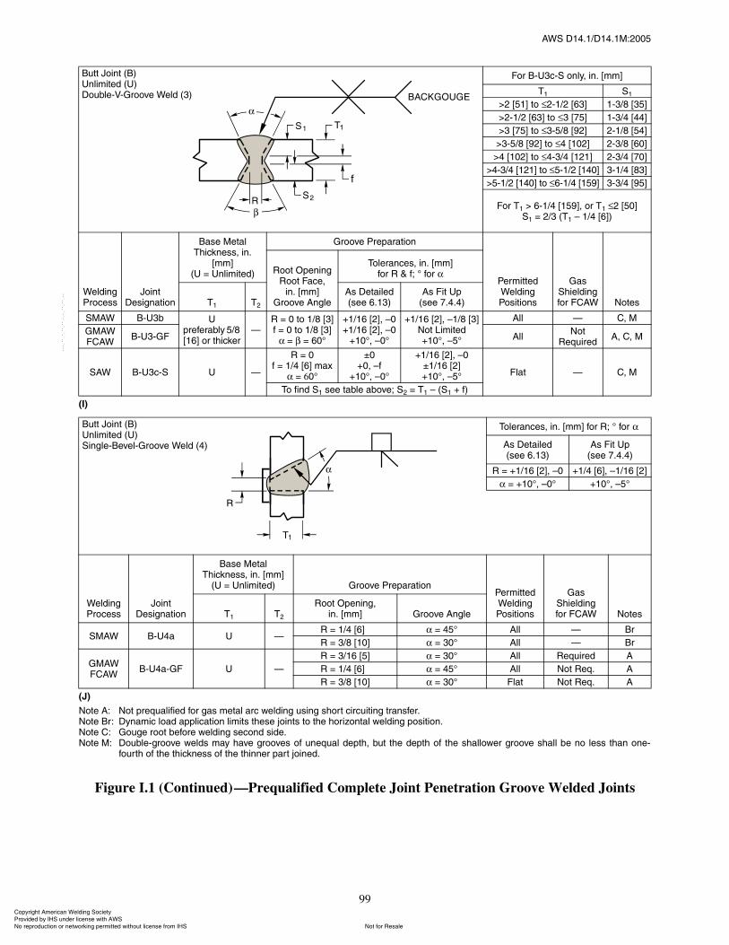
ßÉÍ ÜïìòïñÜïìòïÓæîððë
99
ø×÷
øÖ÷
Ò±¬» ßæ Ò±¬ °®»¯«¿´·º·»¼ º±® ¹¿ ³»¬¿´ ¿®½ ©»´¼·²¹ «·²¹ ¸±®¬ ½·®½«·¬·²¹ ¬®¿²º»®òÒ±¬» Þ®æ ܧ²¿³·½ ´±¿¼ ¿°°´·½¿¬·±² ´·³·¬ ¬¸»» ¶±·²¬ ¬± ¬¸» ¸±®·¦±²¬¿´ ©»´¼·²¹ °±·¬·±²òÒ±¬» Ýæ Ù±«¹» ®±±¬ ¾»º±®» ©»´¼·²¹ »½±²¼ ·¼»òÒ±¬» Óæ ܱ«¾´»ó¹®±±ª» ©»´¼ ³¿§ ¸¿ª» ¹®±±ª» ±º «²»¯«¿´ ¼»°¬¸ô ¾«¬ ¬¸» ¼»°¬¸ ±º ¬¸» ¸¿´´±©»® ¹®±±ª» ¸¿´´ ¾» ²± ´» ¬¸¿² ±²»ó
º±«®¬¸ ±º ¬¸» ¬¸·½µ²» ±º ¬¸» ¬¸·²²»® °¿®¬ ¶±·²»¼ò
Figure I.1 (Continued)�Prequalified Complete Joint Penetration Groove Welded Joints
Ú±® ÞóËí½óÍ ±²´§ô ·²ò ų³Ã
Ìï Íï
âî Åëïà ¬± îóïñî Åêíà ïóíñè ÅíëÃ
âîóïñî Åêíà ¬± í Åéëà ïóíñì ÅììÃ
âí Åéëà ¬± íóëñè Åçîà îóïñè ÅëìÃ
âíóëñè Åçîà ¬± ì Åïðîà îóíñè ÅêðÃ
âì Åïðîà ¬± ìóíñì Åïîïà îóíñì ÅéðÃ
âìóíñì Åïîïà ¬± ëóïñî Åïìðà íóïñì ÅèíÃ
âëóïñî Åïìðà ¬± êóïñì Åïëçà íóíñì ÅçëÃ
Ú±® Ìï â êóïñì ÅïëçÃô ±® Ìï î ÅëðÃÍï ã îñí øÌï � ïñì ÅêÃ÷
É»´¼·²¹ Ю±½»
Ö±·²¬ Ü»·¹²¿¬·±²
Þ¿» Ó»¬¿´ ̸·½µ²»ô ·²ò
ų³ÃøË ã ˲´·³·¬»¼÷
Ù®±±ª» Ю»°¿®¿¬·±²
л®³·¬¬»¼ É»´¼·²¹ б·¬·±²
Ù¿ ͸·»´¼·²¹ º±® ÚÝßÉ Ò±¬»
ᱬ Ñ°»²·²¹Î±±¬ Ú¿½»ô
·²ò ų³ÃÙ®±±ª» ß²¹´»
̱´»®¿²½»ô ·²ò ų³Ãº±® Î ú ºå p º±®
Ìï Ìî
ß Ü»¬¿·´»¼ø»» êòïí÷
ß Ú·¬ Ë°ø»» éòìòì÷
ÍÓßÉ ÞóËí¾ Ë°®»º»®¿¾´§ ëñè Åïêà ±® ¬¸·½µ»®
�Î ã 𠬱 ïñè Åíú ã 𠬱 ïñè ÅíÃ
ã ã êðp
õïñïê ÅîÃô �ðõïñïê ÅîÃô �ð
õïðpô �ðp
õïñïê ÅîÃô �ïñè ÅíÃÒ±¬ Ô·³·¬»¼õïðpô �ëp
ß´´ � Ýô Ó
ÙÓßÉÚÝßÉ
ÞóËíóÙÚ ß´´Ò±¬
λ¯«·®»¼ßô Ýô Ó
ÍßÉ ÞóËí½óÍ Ë �
Î ã ðº ã ïñì Åêà ³¿¨
ã êðp
oðõðô �º
õïðpô �ðp
õïñïê ÅîÃô �ðoïñïê ÅîÃõïðpô �ëp Ú´¿¬ � Ýô Ó
̱ º·²¼ Íï »» ¬¿¾´» ¿¾±ª»å Íî ã Ìï � øÍï õ º÷
̱´»®¿²½»ô ·²ò ų³Ã º±® Îå p º±®
ß Ü»¬¿·´»¼ø»» êòïí÷
ß Ú·¬ Ë°ø»» éòìòì÷
Î ã õïñïê ÅîÃô �ð õïñì ÅêÃô �ïñïê ÅîÃ
ã õïðpô �ðp õïðpô �ëp
É»´¼·²¹ Ю±½»
Ö±·²¬ Ü»·¹²¿¬·±²
Þ¿» Ó»¬¿´ ̸·½µ²»ô ·²ò ų³Ã
øË ã ˲´·³·¬»¼÷ Ù®±±ª» Ю»°¿®¿¬·±²Ð»®³·¬¬»¼ É»´¼·²¹ б·¬·±²
Ù¿ ͸·»´¼·²¹º±® ÚÝßÉ Ò±¬»Ìï Ìî
ᱬ Ñ°»²·²¹ô·²ò ų³Ã Ù®±±ª» ß²¹´»
ÍÓßÉ ÞóËì¿ Ë �Î ã ïñì ÅêÃð ã ìëp ß´´ � Þ®
Î ã íñè Åïðà ã íðp ß´´ � Þ®
ÙÓßÉÚÝßÉ
ÞóËì¿óÙÚ Ë �
Î ã íñïê Åëà ã íðp ß´´ λ¯«·®»¼ ß
Î ã ïñì ÅêÃð ã ìëp ß´´ Ò±¬ λ¯ò ß
Î ã íñè Åïðà ã íðp Ú´¿¬ Ò±¬ λ¯ò ß
Þ«¬¬ Ö±·²¬ øÞ÷˲´·³·¬»¼ øË÷ܱ«¾´»óÊóÙ®±±ª» É»´¼ øí÷
Þ«¬¬ Ö±·²¬ øÞ÷˲´·³·¬»¼ øË÷Í·²¹´»óÞ»ª»´óÙ®±±ª» É»´¼ øì÷
ݱ°§®·¹¸¬ ß³»®·½¿² É»´¼·²¹ ͱ½·»¬§ Ю±ª·¼»¼ ¾§ ×ØÍ «²¼»® ´·½»²» ©·¬¸ ßÉÍ
Ò±¬ º±® λ¿´»Ò± ®»°®±¼«½¬·±² ±® ²»¬©±®µ·²¹ °»®³·¬¬»¼ ©·¬¸±«¬ ´·½»²» º®±³ ×ØÍ
óóÀôôÀôôÀóÀóÀôôÀôôÀôÀôôÀóóó
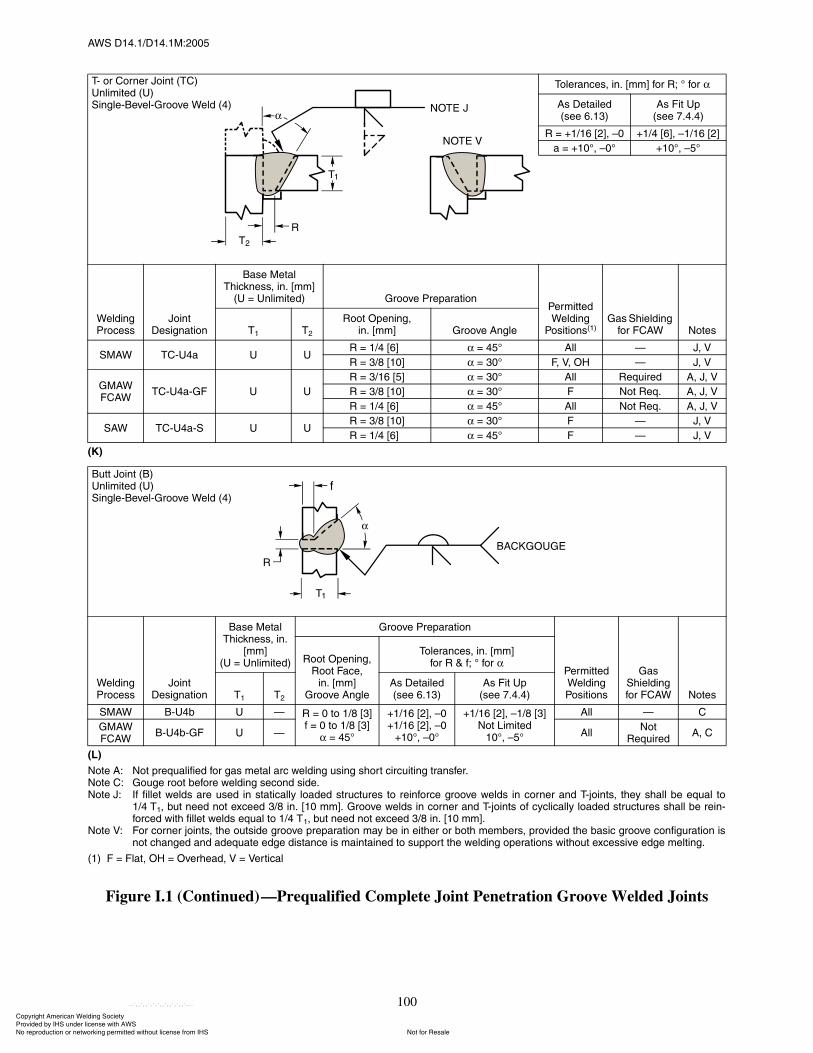
ßÉÍ ÜïìòïñÜïìòïÓæîððë
100
øÕ÷
øÔ÷
Ò±¬» ßæ Ò±¬ °®»¯«¿´·º·»¼ º±® ¹¿ ³»¬¿´ ¿®½ ©»´¼·²¹ «·²¹ ¸±®¬ ½·®½«·¬·²¹ ¬®¿²º»®òÒ±¬» Ýæ Ù±«¹» ®±±¬ ¾»º±®» ©»´¼·²¹ »½±²¼ ·¼»òÒ±¬» Öæ ׺ º·´´»¬ ©»´¼ ¿®» «»¼ ·² ¬¿¬·½¿´´§ ´±¿¼»¼ ¬®«½¬«®» ¬± ®»·²º±®½» ¹®±±ª» ©»´¼ ·² ½±®²»® ¿²¼ Ì󶱷²¬ô ¬¸»§ ¸¿´´ ¾» »¯«¿´ ¬±
ïñì Ìïô ¾«¬ ²»»¼ ²±¬ »¨½»»¼ íñè ·²ò Åïð ³³Ãò Ù®±±ª» ©»´¼ ·² ½±®²»® ¿²¼ Ì󶱷²¬ ±º ½§½´·½¿´´§ ´±¿¼»¼ ¬®«½¬«®» ¸¿´´ ¾» ®»·²óº±®½»¼ ©·¬¸ º·´´»¬ ©»´¼ »¯«¿´ ¬± ïñì Ìïô ¾«¬ ²»»¼ ²±¬ »¨½»»¼ íñè ·²ò Åïð ³³Ãò
Ò±¬» Êæ Ú±® ½±®²»® ¶±·²¬ô ¬¸» ±«¬·¼» ¹®±±ª» °®»°¿®¿¬·±² ³¿§ ¾» ·² »·¬¸»® ±® ¾±¬¸ ³»³¾»®ô °®±ª·¼»¼ ¬¸» ¾¿·½ ¹®±±ª» ½±²º·¹«®¿¬·±² ·²±¬ ½¸¿²¹»¼ ¿²¼ ¿¼»¯«¿¬» »¼¹» ¼·¬¿²½» · ³¿·²¬¿·²»¼ ¬± «°°±®¬ ¬¸» ©»´¼·²¹ ±°»®¿¬·±² ©·¬¸±«¬ »¨½»·ª» »¼¹» ³»´¬·²¹ò
øï÷ Ú ã Ú´¿¬ô ÑØ ã Ѫ»®¸»¿¼ô Ê ã Ê»®¬·½¿´
Figure I.1 (Continued)�Prequalified Complete Joint Penetration Groove Welded Joints
̱´»®¿²½»ô ·²ò ų³Ã º±® Îå p º±®
ß Ü»¬¿·´»¼ø»» êòïí÷
ß Ú·¬ Ë°ø»» éòìòì÷
Î ã õïñïê ÅîÃô �ð õïñì ÅêÃô �ïñïê ÅîÃ
¿ ã õïðpô �ðp õïðpô �ëp
É»´¼·²¹ Ю±½»
Ö±·²¬ Ü»·¹²¿¬·±²
Þ¿» Ó»¬¿´ ̸·½µ²»ô ·²ò ų³Ã
øË ã ˲´·³·¬»¼÷ Ù®±±ª» Ю»°¿®¿¬·±²Ð»®³·¬¬»¼ É»´¼·²¹
б·¬·±²øï÷Ù¿ ͸·»´¼·²¹
º±® ÚÝßÉ Ò±¬»Ìï Ìî
ᱬ Ñ°»²·²¹ô·²ò ų³Ã Ù®±±ª» ß²¹´»
ÍÓßÉ ÌÝóËì¿ Ë ËÎ ã ïñì ÅêÃð ã ìëp ß´´ � Öô Ê
Î ã íñè Åïðà ã íðp Úô Êô ÑØ � Öô Ê
ÙÓßÉÚÝßÉ
ÌÝóËì¿óÙÚ Ë Ë
Î ã íñïê Åëà ã íðp ß´´ λ¯«·®»¼ ßô Öô Ê
Î ã íñè Åïðà ã íðp Ú Ò±¬ λ¯ò ßô Öô Ê
Î ã ïñì ÅêÃð ã ìëp ß´´ Ò±¬ λ¯ò ßô Öô Ê
ÍßÉ ÌÝóËì¿óÍ Ë ËÎ ã íñè Åïðà ã íðp Ú � Öô Ê
Î ã ïñì ÅêÃð ã ìëp Ú � Öô Ê
Þ«¬¬ Ö±·²¬ øÞ÷˲´·³·¬»¼ øË÷Í·²¹´»óÞ»ª»´óÙ®±±ª» É»´¼ øì÷
É»´¼·²¹ Ю±½»
Ö±·²¬ Ü»·¹²¿¬·±²
Þ¿» Ó»¬¿´ ̸·½µ²»ô ·²ò
ų³ÃøË ã ˲´·³·¬»¼÷
Ù®±±ª» Ю»°¿®¿¬·±²
л®³·¬¬»¼ É»´¼·²¹ б·¬·±²
Ù¿ ͸·»´¼·²¹ º±® ÚÝßÉ Ò±¬»
ᱬ Ñ°»²·²¹ôᱬ Ú¿½»ô
·²ò ų³ÃÙ®±±ª» ß²¹´»
̱´»®¿²½»ô ·²ò ų³Ãº±® Î ú ºå p º±®
Ìï Ìî
ß Ü»¬¿·´»¼ø»» êòïí÷
ß Ú·¬ Ë°ø»» éòìòì÷
ÍÓßÉ ÞóËì¾ Ë � Î ã 𠬱 ïñè Åíú ã 𠬱 ïñè ÅíÃ
ã ìëp
õïñïê ÅîÃô �ðõïñïê ÅîÃô �ð
õïðpô �ðp
õïñïê ÅîÃô �ïñè ÅíÃÒ±¬ Ô·³·¬»¼
ïðpô �ëp
ß´´ � Ý
ÙÓßÉÚÝßÉ
ÞóËì¾óÙÚ Ë � ß´´Ò±¬
λ¯«·®»¼ßô Ý
Ìó ±® ݱ®²»® Ö±·²¬ øÌÝ÷˲´·³·¬»¼ øË÷Í·²¹´»óÞ»ª»´óÙ®±±ª» É»´¼ øì÷
ݱ°§®·¹¸¬ ß³»®·½¿² É»´¼·²¹ ͱ½·»¬§ Ю±ª·¼»¼ ¾§ ×ØÍ «²¼»® ´·½»²» ©·¬¸ ßÉÍ
Ò±¬ º±® λ¿´»Ò± ®»°®±¼«½¬·±² ±® ²»¬©±®µ·²¹ °»®³·¬¬»¼ ©·¬¸±«¬ ´·½»²» º®±³ ×ØÍ
óóÀôôÀôôÀóÀóÀôôÀôôÀôÀôôÀóóó
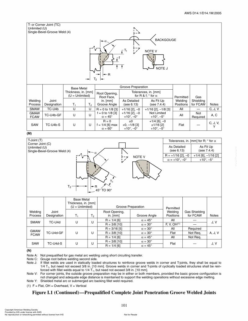
ßÉÍ ÜïìòïñÜïìòïÓæîððë
101
øÓ÷
øÒ÷
Ò±¬» ßæ Ò±¬ °®»¯«¿´·º·»¼ º±® ¹¿ ³»¬¿´ ¿®½ ©»´¼·²¹ «·²¹ ¸±®¬ ½·®½«·¬·²¹ ¬®¿²º»®òÒ±¬» Ýæ Ù±«¹» ®±±¬ ¾»º±®» ©»´¼·²¹ »½±²¼ ·¼»òÒ±¬» Öæ ׺ º·´´»¬ ©»´¼ ¿®» «»¼ ·² ¬¿¬·½¿´´§ ´±¿¼»¼ ¬®«½¬«®» ¬± ®»·²º±®½» ¹®±±ª» ©»´¼ ·² ½±®²»® ¿²¼ Ì󶱷²¬ô ¬¸»§ ¸¿´´ ¾» »¯«¿´ ¬±
ïñì Ìïô ¾«¬ ²»»¼ ²±¬ »¨½»»¼ íñè ·²ò Åïð ³³Ãò Ù®±±ª» ©»´¼ ·² ½±®²»® ¿²¼ Ì󶱷²¬ ±º ½§½´·½¿´´§ ´±¿¼»¼ ¬®«½¬«®» ¸¿´´ ¾» ®»·²óº±®½»¼ ©·¬¸ º·´´»¬ ©»´¼ »¯«¿´ ¬± ïñì Ìïô ¾«¬ ²»»¼ ²±¬ »¨½»»¼ íñè ·²ò Åïð ³³Ãò
Ò±¬» Êæ Ú±® ½±®²»® ¶±·²¬ô ¬¸» ±«¬·¼» ¹®±±ª» °®»°¿®¿¬·±² ³¿§ ¾» ·² »·¬¸»® ±® ¾±¬¸ ³»³¾»®ô °®±ª·¼»¼ ¬¸» ¾¿·½ ¹®±±ª» ½±²º·¹«®¿¬·±² ·²±¬ ½¸¿²¹»¼ ¿²¼ ¿¼»¯«¿¬» »¼¹» ¼·¬¿²½» · ³¿·²¬¿·²»¼ ¬± «°°±®¬ ¬¸» ©»´¼·²¹ ±°»®¿¬·±² ©·¬¸±«¬ »¨½»·ª» »¼¹» ³»´¬·²¹ò
Ò±¬» Çæ ͸·»´¼»¼ ³»¬¿´ ¿®½ ±® «¾³»®¹»¼ ¿®½ ¾¿½µ·²¹ º·´´»¬ ©»´¼ ®»¯«·®»¼ò
øï÷ Ú ã Ú´¿¬ô ÑØ ã Ѫ»®¸»¿¼ô Ê ã Ê»®¬·½¿´
Figure I.1 (Continued)�Prequalified Complete Joint Penetration Groove Welded Joints
Ìó ±® ݱ®²»® Ö±·²¬ øÌÝ÷˲´·³·¬»¼ øË÷Í·²¹´»óÞ»ª»´óÙ®±±ª» É»´¼ øì÷
É»´¼·²¹ Ю±½»
Ö±·²¬ Ü»·¹²¿¬·±²
Þ¿» Ó»¬¿´ ̸·½µ²»ô ·²ò ų³Ã
øË ã ˲´·³·¬»¼÷
Ù®±±ª» Ю»°¿®¿¬·±²
л®³·¬¬»¼ É»´¼·²¹ б·¬·±²
Ù¿ ͸·»´¼·²¹ º±® ÚÝßÉ Ò±¬»
ᱬ Ñ°»²·²¹ôᱬ Ú¿½»ô
·²ò ų³ÃÙ®±±ª» ß²¹´»
̱´»®¿²½»ô ·²ò ų³Ã º±® Î ú ºå p º±®
Ìï Ìî
ß Ü»¬¿·´»¼ø»» êòïí÷
ß Ú·¬ Ë°ø»» éòìòì÷
ÍÓßÉ ÌÝóËì¾ Ë Ë Î ã 𠬱 ïñè Åíú ã 𠬱 ïñè ÅíÃ
ã ìëp
õïñïê ÅîÃô �ðõïñïê ÅîÃô �ð
õïðpô �ðp
õïñïê ÅîÃô �ïñè ÅíÃÒ±¬ Ô·³·¬»¼õïðpô �ëp
ß´´ � Ýô Öô Ê
ÙÓßÉÚÝßÉ
ÌÝóËì¾óÙÚ Ë Ë ß´´Ò±¬
λ¯«·®»¼ßô Ý
ÍßÉ ÌÝóËì¾óÍ Ë ËÎ ã ð
º ã ïñì Åêà ³¿¨ ã êðp
oðõðô �ïñè ÅíÃõïðpô �ðp
õïñì ÅêÃô �ðoïñïê ÅîÃõïðpô �ëp
Ú´¿¬ �Ýô Öô Êô
Ç
̱´»®¿²½»ô ·²ò ų³Ã º±® Îå p º±®
ß Ü»¬¿·´»¼ø»» êòïí÷
ß Ú·¬ Ë°ø»» éòìòì÷
Î ã õïñïê ÅîÃô �ð õïñì ÅêÃô �ïñïê ÅîÃ
ã õïðpô �ðp õïðpô �ëp
É»´¼·²¹ Ю±½»
Ö±·²¬ Ü»·¹²¿¬·±²
Þ¿» Ó»¬¿´ ̸·½µ²»ô ·²ò ų³Ã
øË ã ˲´·³·¬»¼÷ Ù®±±ª» Ю»°¿®¿¬·±² л®³·¬¬»¼ É»´¼·²¹ б·¬·±²
Ù¿ ͸·»´¼·²¹ º±® ÚÝßÉ Ò±¬»Ìï Ìî
ᱬ Ñ°»²·²¹ô·²ò ų³Ã Ù®±±ª» ß²¹´»
ÍÓßÉ ÌÝóËì¼ Ë ËÎ ã ïñì ÅêÃð ã ìëp ß´´ �
Öô ÊÎ ã íñè Åïðà ã íðp Úô Êô ÑØøï÷ �
ÙÓßÉÚÝßÉ
ÌÝóËì¼óÙÚ Ë Ë
Î ã íñïê Åëà ã íðp ß´´ λ¯«·®»¼
ßô Öô ÊÎ ã íñè Åïðà ã íðp Ú´¿¬ Ò±¬ λ¯ò
Î ã ïñì ÅêÃð ã ìëp ß´´ Ò±¬ λ¯ò
ÍßÉ ÌÝóËì¼óÍ Ë ËÎ ã íñè Åïðà ã íðp
Ú´¿¬ � Öô ÊÎ ã ïñì ÅêÃð ã ìëp
ÌóÖ±·²¬ øÌ÷ݱ®²»® Ö±·²¬ øÝ÷˲´·³·¬»¼ øË÷Í·²¹´»óÞ»ª»´óÙ®±±ª» É»´¼ øì÷
ݱ°§®·¹¸¬ ß³»®·½¿² É»´¼·²¹ ͱ½·»¬§ Ю±ª·¼»¼ ¾§ ×ØÍ «²¼»® ´·½»²» ©·¬¸ ßÉÍ
Ò±¬ º±® λ¿´»Ò± ®»°®±¼«½¬·±² ±® ²»¬©±®µ·²¹ °»®³·¬¬»¼ ©·¬¸±«¬ ´·½»²» º®±³ ×ØÍ
óóÀôôÀôôÀóÀóÀôôÀôôÀôÀôôÀóóó
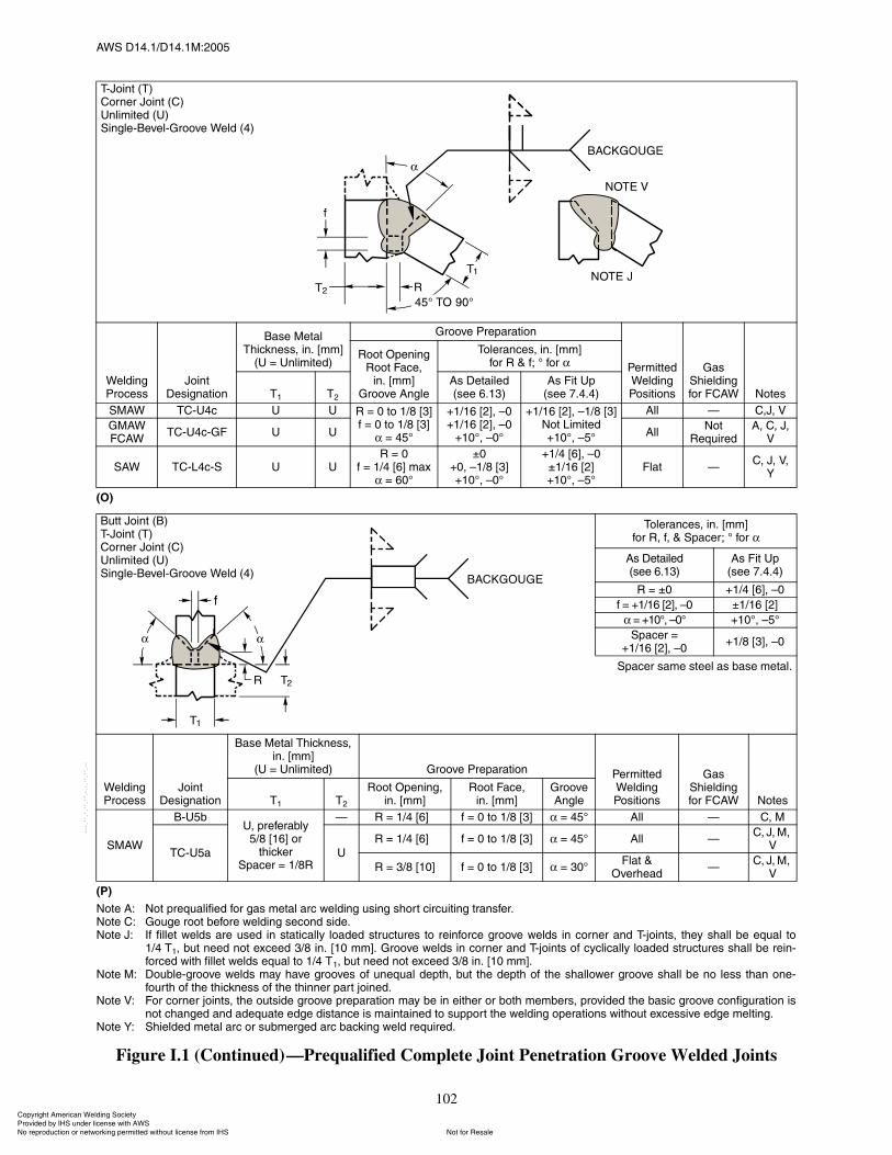
ßÉÍ ÜïìòïñÜïìòïÓæîððë
102
øÑ÷
øÐ÷
Ò±¬» ßæ Ò±¬ °®»¯«¿´·º·»¼ º±® ¹¿ ³»¬¿´ ¿®½ ©»´¼·²¹ «·²¹ ¸±®¬ ½·®½«·¬·²¹ ¬®¿²º»®òÒ±¬» Ýæ Ù±«¹» ®±±¬ ¾»º±®» ©»´¼·²¹ »½±²¼ ·¼»òÒ±¬» Öæ ׺ º·´´»¬ ©»´¼ ¿®» «»¼ ·² ¬¿¬·½¿´´§ ´±¿¼»¼ ¬®«½¬«®» ¬± ®»·²º±®½» ¹®±±ª» ©»´¼ ·² ½±®²»® ¿²¼ Ì󶱷²¬ô ¬¸»§ ¸¿´´ ¾» »¯«¿´ ¬±
ïñì Ìïô ¾«¬ ²»»¼ ²±¬ »¨½»»¼ íñè ·²ò Åïð ³³Ãò Ù®±±ª» ©»´¼ ·² ½±®²»® ¿²¼ Ì󶱷²¬ ±º ½§½´·½¿´´§ ´±¿¼»¼ ¬®«½¬«®» ¸¿´´ ¾» ®»·²óº±®½»¼ ©·¬¸ º·´´»¬ ©»´¼ »¯«¿´ ¬± ïñì Ìïô ¾«¬ ²»»¼ ²±¬ »¨½»»¼ íñè ·²ò Åïð ³³Ãò
Ò±¬» Óæ ܱ«¾´»ó¹®±±ª» ©»´¼ ³¿§ ¸¿ª» ¹®±±ª» ±º «²»¯«¿´ ¼»°¬¸ô ¾«¬ ¬¸» ¼»°¬¸ ±º ¬¸» ¸¿´´±©»® ¹®±±ª» ¸¿´´ ¾» ²± ´» ¬¸¿² ±²»óº±«®¬¸ ±º ¬¸» ¬¸·½µ²» ±º ¬¸» ¬¸·²²»® °¿®¬ ¶±·²»¼ò
Ò±¬» Êæ Ú±® ½±®²»® ¶±·²¬ô ¬¸» ±«¬·¼» ¹®±±ª» °®»°¿®¿¬·±² ³¿§ ¾» ·² »·¬¸»® ±® ¾±¬¸ ³»³¾»®ô °®±ª·¼»¼ ¬¸» ¾¿·½ ¹®±±ª» ½±²º·¹«®¿¬·±² ·²±¬ ½¸¿²¹»¼ ¿²¼ ¿¼»¯«¿¬» »¼¹» ¼·¬¿²½» · ³¿·²¬¿·²»¼ ¬± «°°±®¬ ¬¸» ©»´¼·²¹ ±°»®¿¬·±² ©·¬¸±«¬ »¨½»·ª» »¼¹» ³»´¬·²¹ò
Ò±¬» Çæ ͸·»´¼»¼ ³»¬¿´ ¿®½ ±® «¾³»®¹»¼ ¿®½ ¾¿½µ·²¹ ©»´¼ ®»¯«·®»¼ò
Figure I.1 (Continued)�Prequalified Complete Joint Penetration Groove Welded Joints
ÌóÖ±·²¬ øÌ÷ݱ®²»® Ö±·²¬ øÝ÷˲´·³·¬»¼ øË÷Í·²¹´»óÞ»ª»´óÙ®±±ª» É»´¼ øì÷
É»´¼·²¹ Ю±½»
Ö±·²¬ Ü»·¹²¿¬·±²
Þ¿» Ó»¬¿´ ̸·½µ²»ô ·²ò ų³Ã
øË ã ˲´·³·¬»¼÷
Ù®±±ª» Ю»°¿®¿¬·±²
л®³·¬¬»¼ É»´¼·²¹ б·¬·±²
Ù¿ ͸·»´¼·²¹ º±® ÚÝßÉ Ò±¬»
ᱬ Ñ°»²·²¹Î±±¬ Ú¿½»ô
·²ò ų³ÃÙ®±±ª» ß²¹´»
̱´»®¿²½»ô ·²ò ų³Ãº±® Î ú ºå p º±®
Ìï Ìî
ß Ü»¬¿·´»¼ø»» êòïí÷
ß Ú·¬ Ë°ø»» éòìòì÷
ÍÓßÉ ÌÝóËì½ Ë Ë Î ã 𠬱 ïñè Åíú ã 𠬱 ïñè ÅíÃ
ã ìëp
õïñïê ÅîÃô �ðõïñïê ÅîÃô �ð
õïðpô �ðp
õïñïê ÅîÃô �ïñè ÅíÃÒ±¬ Ô·³·¬»¼õïðpô �ëp
ß´´ � ÝôÖô Ê
ÙÓßÉÚÝßÉ
ÌÝóËì½óÙÚ Ë Ë ß´´Ò±¬
λ¯«·®»¼ßô Ýô Öô
Ê
ÍßÉ ÌÝóÔì½óÍ Ë ËÎ ã ð
º ã ïñì Åêà ³¿¨ ã êðp
oðõðô �ïñè ÅíÃõïðpô �ðp
õïñì ÅêÃô �ðoïñïê ÅîÃõïðpô �ëp
Ú´¿¬ �Ýô Öô Êô
Ç
̱´»®¿²½»ô ·²ò ų³Ãº±® Îô ºô ú Í°¿½»®å p º±®
ß Ü»¬¿·´»¼ø»» êòïí÷
ß Ú·¬ Ë°ø»» éòìòì÷
Î ã oð õïñì ÅêÃô �ð
º ã õïñïê ÅîÃô �ð oïñïê ÅîÃ
ã õïðpô �ðp õïðpô �ëp
Í°¿½»® ãõïñïê ÅîÃô �ð
õïñè ÅíÃô �ð
Í°¿½»® ¿³» ¬»»´ ¿ ¾¿» ³»¬¿´ò
É»´¼·²¹ Ю±½»
Ö±·²¬ Ü»·¹²¿¬·±²
Þ¿» Ó»¬¿´ ̸·½µ²»ô ·²ò ų³Ã
øË ã ˲´·³·¬»¼÷ Ù®±±ª» Ю»°¿®¿¬·±² л®³·¬¬»¼ É»´¼·²¹ б·¬·±²
Ù¿ ͸·»´¼·²¹ º±® ÚÝßÉ Ò±¬»Ìï Ìî
ᱬ Ñ°»²·²¹ô·²ò ų³Ã
ᱬ Ú¿½»ô·²ò ų³Ã
Ù®±±ª» ß²¹´»
ÍÓßÉ
ÞóËë¾Ëô °®»º»®¿¾´§
ëñè Åïêà ±® ¬¸·½µ»®
Í°¿½»® ã ïñèÎ
� Î ã ïñì ÅêÃð º ã 𠬱 ïñè Åíà ã ìëp ß´´ � Ýô Ó
ÌÝóËë¿ Ë
Î ã ïñì ÅêÃð º ã 𠬱 ïñè Åíà ã ìëp ß´´ �Ýô Öô Óô
Ê
Î ã íñè Åïðà º ã 𠬱 ïñè Åíà ã íðpÚ´¿¬ ú
Ѫ»®¸»¿¼�
Ýô Öô Óô Ê
Þ«¬¬ Ö±·²¬ øÞ÷ÌóÖ±·²¬ øÌ÷ݱ®²»® Ö±·²¬ øÝ÷˲´·³·¬»¼ øË÷Í·²¹´»óÞ»ª»´óÙ®±±ª» É»´¼ øì÷
ݱ°§®·¹¸¬ ß³»®·½¿² É»´¼·²¹ ͱ½·»¬§ Ю±ª·¼»¼ ¾§ ×ØÍ «²¼»® ´·½»²» ©·¬¸ ßÉÍ
Ò±¬ º±® λ¿´»Ò± ®»°®±¼«½¬·±² ±® ²»¬©±®µ·²¹ °»®³·¬¬»¼ ©·¬¸±«¬ ´·½»²» º®±³ ×ØÍ
óóÀôôÀôôÀóÀóÀôôÀôôÀôÀôôÀóóó
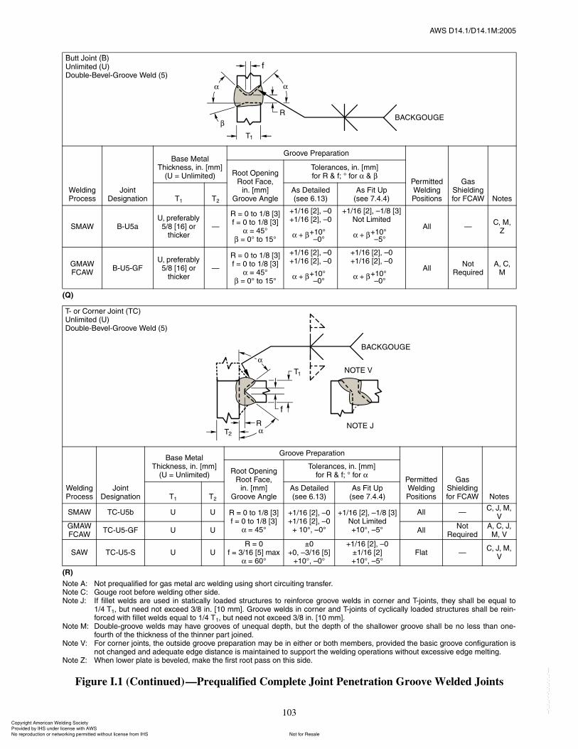
ßÉÍ ÜïìòïñÜïìòïÓæîððë
103
øÏ÷
øÎ÷
Ò±¬» ßæ Ò±¬ °®»¯«¿´·º·»¼ º±® ¹¿ ³»¬¿´ ¿®½ ©»´¼·²¹ «·²¹ ¸±®¬ ½·®½«·¬·²¹ ¬®¿²º»®òÒ±¬» Ýæ Ù±«¹» ®±±¬ ¾»º±®» ©»´¼·²¹ ±¬¸»® ·¼»òÒ±¬» Öæ ׺ º·´´»¬ ©»´¼ ¿®» «»¼ ·² ¬¿¬·½¿´´§ ´±¿¼»¼ ¬®«½¬«®» ¬± ®»·²º±®½» ¹®±±ª» ©»´¼ ·² ½±®²»® ¿²¼ Ì󶱷²¬ô ¬¸»§ ¸¿´´ ¾» »¯«¿´ ¬±
ïñì Ìïô ¾«¬ ²»»¼ ²±¬ »¨½»»¼ íñè ·²ò Åïð ³³Ãò Ù®±±ª» ©»´¼ ·² ½±®²»® ¿²¼ Ì󶱷²¬ ±º ½§½´·½¿´´§ ´±¿¼»¼ ¬®«½¬«®» ¸¿´´ ¾» ®»·²óº±®½»¼ ©·¬¸ º·´´»¬ ©»´¼ »¯«¿´ ¬± ïñì Ìïô ¾«¬ ²»»¼ ²±¬ »¨½»»¼ íñè ·²ò Åïð ³³Ãò
Ò±¬» Óæ ܱ«¾´»ó¹®±±ª» ©»´¼ ³¿§ ¸¿ª» ¹®±±ª» ±º «²»¯«¿´ ¼»°¬¸ô ¾«¬ ¬¸» ¼»°¬¸ ±º ¬¸» ¸¿´´±©»® ¹®±±ª» ¸¿´´ ¾» ²± ´» ¬¸¿² ±²»óº±«®¬¸ ±º ¬¸» ¬¸·½µ²» ±º ¬¸» ¬¸·²²»® °¿®¬ ¶±·²»¼ò
Ò±¬» Êæ Ú±® ½±®²»® ¶±·²¬ô ¬¸» ±«¬·¼» ¹®±±ª» °®»°¿®¿¬·±² ³¿§ ¾» ·² »·¬¸»® ±® ¾±¬¸ ³»³¾»®ô °®±ª·¼»¼ ¬¸» ¾¿·½ ¹®±±ª» ½±²º·¹«®¿¬·±² ·²±¬ ½¸¿²¹»¼ ¿²¼ ¿¼»¯«¿¬» »¼¹» ¼·¬¿²½» · ³¿·²¬¿·²»¼ ¬± «°°±®¬ ¬¸» ©»´¼·²¹ ±°»®¿¬·±² ©·¬¸±«¬ »¨½»·ª» »¼¹» ³»´¬·²¹ò
Ò±¬» Ææ ɸ»² ´±©»® °´¿¬» · ¾»ª»´»¼ô ³¿µ» ¬¸» º·®¬ ®±±¬ °¿ ±² ¬¸· ·¼»ò
Figure I.1 (Continued)�Prequalified Complete Joint Penetration Groove Welded Joints
Þ«¬¬ Ö±·²¬ øÞ÷˲´·³·¬»¼ øË÷ܱ«¾´»óÞ»ª»´óÙ®±±ª» É»´¼ øë÷
É»´¼·²¹ Ю±½»
Ö±·²¬ Ü»·¹²¿¬·±²
Þ¿» Ó»¬¿´ ̸·½µ²»ô ·²ò ų³Ã
øË ã ˲´·³·¬»¼÷
Ù®±±ª» Ю»°¿®¿¬·±²
л®³·¬¬»¼ É»´¼·²¹ б·¬·±²
Ù¿ ͸·»´¼·²¹ º±® ÚÝßÉ Ò±¬»
ᱬ Ñ°»²·²¹Î±±¬ Ú¿½»ô
·²ò ų³ÃÙ®±±ª» ß²¹´»
̱´»®¿²½»ô ·²ò ų³Ãº±® Î ú ºå p º±® ú
Ìï Ìî
ß Ü»¬¿·´»¼ø»» êòïí÷
ß Ú·¬ Ë°ø»» éòìòì÷
ÍÓßÉ ÞóËë¿Ëô °®»º»®¿¾´§
ëñè Åïêà ±® ¬¸·½µ»®
�
Î ã 𠬱 ïñè Åíú ã 𠬱 ïñè ÅíÃ
ã ìëp ã ðp ¬± ïëp
õïñïê ÅîÃô �ðõïñïê ÅîÃô �ð
õïñïê ÅîÃô �ïñè ÅíÃÒ±¬ Ô·³·¬»¼
ß´´ �Ýô Óô
Æ
ÙÓßÉÚÝßÉ
ÞóËëóÙÚËô °®»º»®¿¾´§
ëñè Åïêà ±® ¬¸·½µ»®
�
Î ã 𠬱 ïñè Åíú ã 𠬱 ïñè ÅíÃ
ã ìëp ã ðp ¬± ïëp
õïñïê ÅîÃô �ðõïñïê ÅîÃô �ð
õïñïê ÅîÃô �ðõïñïê ÅîÃô �ð
ß´´Ò±¬
λ¯«·®»¼ßô Ýô
Ó
Ìó ±® ݱ®²»® Ö±·²¬ øÌÝ÷˲´·³·¬»¼ øË÷ܱ«¾´»óÞ»ª»´óÙ®±±ª» É»´¼ øë÷
É»´¼·²¹ Ю±½»
Ö±·²¬ Ü»·¹²¿¬·±²
Þ¿» Ó»¬¿´ ̸·½µ²»ô ·²ò ų³Ã
øË ã ˲´·³·¬»¼÷
Ù®±±ª» Ю»°¿®¿¬·±²
л®³·¬¬»¼ É»´¼·²¹ б·¬·±²
Ù¿ ͸·»´¼·²¹ º±® ÚÝßÉ Ò±¬»
ᱬ Ñ°»²·²¹Î±±¬ Ú¿½»ô
·²ò ų³ÃÙ®±±ª» ß²¹´»
̱´»®¿²½»ô ·²ò ų³Ãº±® Î ú ºå p º±®
Ìï Ìî
ß Ü»¬¿·´»¼ø»» êòïí÷
ß Ú·¬ Ë°ø»» éòìòì÷
ÍÓßÉ ÌÝóËë¾ Ë Ë Î ã 𠬱 ïñè Åíú ã 𠬱 ïñè ÅíÃ
ã ìëp
õïñïê ÅîÃô �ðõïñïê ÅîÃô �ð
õ ïðpô �ðp
õïñïê ÅîÃô �ïñè ÅíÃÒ±¬ Ô·³·¬»¼õïðpô �ëp
ß´´ �Ýô Öô Óô
Ê
ÙÓßÉÚÝßÉ
ÌÝóËëóÙÚ Ë Ë ß´´Ò±¬
λ¯«·®»¼ßô Ýô Öô
Óô Ê
ÍßÉ ÌÝóËëóÍ Ë ËÎ ã ð
º ã íñïê Åëà ³¿¨ã êðp
oðõðô �íñïê ÅëÃ
õïðpô �ðp
õïñïê ÅîÃô �ðoïñïê ÅîÃõïðpô �ëp
Ú´¿¬ �Ýô Öô Óô
Ê
õïðp
�ðp+ õïðp
�ëp+
õïðp
�ðp+ õïðp
�ðp+
Þ«¬¬ Ö±·²¬ øÞ÷˲´·³·¬»¼ øË÷ܱ«¾´»óÞ»ª»´óÙ®±±ª» É»´¼ øë÷
ݱ°§®·¹¸¬ ß³»®·½¿² É»´¼·²¹ ͱ½·»¬§ Ю±ª·¼»¼ ¾§ ×ØÍ «²¼»® ´·½»²» ©·¬¸ ßÉÍ
Ò±¬ º±® λ¿´»Ò± ®»°®±¼«½¬·±² ±® ²»¬©±®µ·²¹ °»®³·¬¬»¼ ©·¬¸±«¬ ´·½»²» º®±³ ×ØÍ
óóÀôôÀôôÀóÀóÀôôÀôôÀôÀôôÀóóó
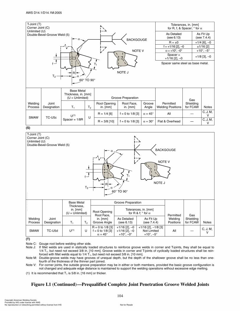
ßÉÍ ÜïìòïñÜïìòïÓæîððë
104
øÍ÷
øÌ÷
Ò±¬» Ýæ Ù±«¹» ®±±¬ ¾»º±®» ©»´¼·²¹ ±¬¸»® ·¼»òÒ±¬» Öæ ׺ º·´´»¬ ©»´¼ ¿®» «»¼ ·² ¬¿¬·½¿´´§ ´±¿¼»¼ ¬®«½¬«®» ¬± ®»·²º±®½» ¹®±±ª» ©»´¼ ·² ½±®²»® ¿²¼ Ì󶱷²¬ô ¬¸»§ ¸¿´´ ¾» »¯«¿´ ¬±
ïñì Ìïô ¾«¬ ²»»¼ ²±¬ »¨½»»¼ íñè ·²ò Åïð ³³Ãò Ù®±±ª» ©»´¼ ·² ½±®²»® ¿²¼ Ì󶱷²¬ ±º ½§½´·½¿´´§ ´±¿¼»¼ ¬®«½¬«®» ¸¿´´ ¾» ®»·²óº±®½»¼ ©·¬¸ º·´´»¬ ©»´¼ »¯«¿´ ¬± ïñì Ìïô ¾«¬ ²»»¼ ²±¬ »¨½»»¼ íñè ·²ò Åïð ³³Ãò
Ò±¬» Óæ ܱ«¾´»ó¹®±±ª» ©»´¼ ³¿§ ¸¿ª» ¹®±±ª» ±º «²»¯«¿´ ¼»°¬¸ô ¾«¬ ¬¸» ¼»°¬¸ ±º ¬¸» ¸¿´´±©»® ¹®±±ª» ¸¿´´ ¾» ²± ´» ¬¸¿² ±²»óº±«®¬¸ ±º ¬¸» ¬¸·½µ²» ±º ¬¸» ¬¸·²²»® °¿®¬ ¶±·²»¼ò
Ò±¬» Êæ Ú±® ½±®²»® ¶±·²¬ô ¬¸» ±«¬·¼» ¹®±±ª» °®»°¿®¿¬·±² ³¿§ ¾» ·² »·¬¸»® ±® ¾±¬¸ ³»³¾»®ô °®±ª·¼»¼ ¬¸» ¾¿·½ ¹®±±ª» ½±²º·¹«®¿¬·±² ·²±¬ ½¸¿²¹»¼ ¿²¼ ¿¼»¯«¿¬» »¼¹» ¼·¬¿²½» · ³¿·²¬¿·²»¼ ¬± «°°±®¬ ¬¸» ©»´¼·²¹ ±°»®¿¬·±² ©·¬¸±«¬ »¨½»·ª» »¼¹» ³»´¬·²¹ò
øï÷ ׬ · ®»½±³³»²¼»¼ ¬¸¿¬ Ìï · ëñè ·²ò Åïê ³³Ã ±® ¬¸·½µ»®ò
Figure I.1 (Continued)�Prequalified Complete Joint Penetration Groove Welded Joints
̱´»®¿²½»ô ·²ò ų³Ãº±® Îô ºô ú Í°¿½»®å p º±®
ß Ü»¬¿·´»¼ø»» êòïí÷
ß Ú·¬ Ë°ø»» éòìòì÷
Î ã oð õïñì ÅêÃô �ð
º ã õïñïê ÅîÃô �ð oïñïê ÅîÃ
ã õïðpô �ðp õïðpô �ëp
Í°¿½»® ãõïñïê ÅîÃô �ð
õïñè ÅíÃô �ð
Í°¿½»® ¿³» ¬»»´ ¿ ¾¿» ³»¬¿´ò
É»´¼·²¹ Ю±½»
Ö±·²¬ Ü»·¹²¿¬·±²
Þ¿» Ó»¬¿´ ̸·½µ²»ô ·²ò ų³Ã
øË ã ˲´·³·¬»¼÷ Ù®±±ª» Ю»°¿®¿¬·±²
л®³·¬¬»¼ É»´¼·²¹ б·¬·±²
Ù¿ ͸·»´¼·²¹ º±® ÚÝßÉ Ò±¬»Ìï Ìî
ᱬ Ñ°»²·²¹·²ò ų³Ã
ᱬ Ú¿½»ô·²ò ų³Ã
Ù®±±ª» ß²¹´»
ÍÓßÉ ÌÝóËë½Ëøï÷
Í°¿½»® ã ïñèÎË
Î ã ïñì ÅêÃð º ã 𠬱 ïñè Åíà ã ìëp ß´´ �Ýô Öô Óô
Ê
Î ã íñè Åïðà º ã 𠬱 ïñè Åíà ã íðp Ú´¿¬ ú Ѫ»®¸»¿¼ �Ýô Öô Óô
Ê
ÌóÖ±·²¬ øÌ÷ݱ®²»® Ö±·²¬ øÝ÷˲´·³·¬»¼ øË÷ܱ«¾´»óÞ»ª»´óÙ®±±ª» É»´¼ øë÷
É»´¼·²¹ Ю±½»
Ö±·²¬ Ü»·¹²¿¬·±²
Þ¿» Ó»¬¿´ ̸·½µ²»ô
·²ò ų³ÃøË ã ˲´·³·¬»¼÷
Ù®±±ª» Ю»°¿®¿¬·±²
л®³·¬¬»¼ É»´¼·²¹ б·¬·±²
Ù¿ ͸·»´¼·²¹ º±® ÚÝßÉ Ò±¬»
ᱬ Ñ°»²·²¹Î±±¬ Ú¿½»ô
·²ò ų³ÃÙ®±±ª» ß²¹´»
̱´»®¿²½»ô ·²ò ų³Ãº±® Î ú ºå p º±®
Ìï Ìî
ß Ü»¬¿·´»¼ø»» êòïí÷
ß Ú·¬ Ë°ø»» éòìòì÷
ÍÓßÉ ÌÝóËë¼ Ëøï÷ ËÎ ã 𠬱 ïñè Åíú ã 𠬱 ïñè ÅíÃ
ã ìëp
õïñïê ÅîÃô �ðõïñïê ÅîÃô �ð
õïðpô �ðp
õïñïê ÅîÃô �ïñè ÅíÃÒ±¬ Ô·³·¬»¼õïðpô �ëp
ß´´ �Ýô Öô Óô
Ê
ÌóÖ±·²¬ øÌ÷ݱ®²»® Ö±·²¬ øÝ÷˲´·³·¬»¼ øË÷ܱ«¾´»óÞ»ª»´óÙ®±±ª» É»´¼ øë÷
ݱ°§®·¹¸¬ ß³»®·½¿² É»´¼·²¹ ͱ½·»¬§ Ю±ª·¼»¼ ¾§ ×ØÍ «²¼»® ´·½»²» ©·¬¸ ßÉÍ
Ò±¬ º±® λ¿´»Ò± ®»°®±¼«½¬·±² ±® ²»¬©±®µ·²¹ °»®³·¬¬»¼ ©·¬¸±«¬ ´·½»²» º®±³ ×ØÍ
óóÀôôÀôôÀóÀóÀôôÀôôÀôÀôôÀóóó
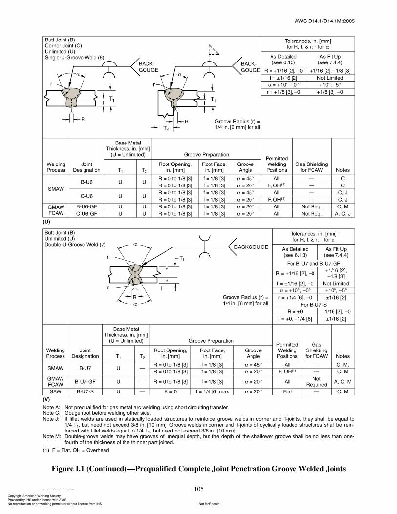
ßÉÍ ÜïìòïñÜïìòïÓæîððë
105
øË÷
øÊ÷
Ò±¬» ßæ Ò±¬ °®»¯«¿´·º·»¼ º±® ¹¿ ³»¬¿´ ¿®½ ©»´¼·²¹ «·²¹ ¸±®¬ ½·®½«·¬·²¹ ¬®¿²º»®òÒ±¬» Ýæ Ù±«¹» ®±±¬ ¾»º±®» ©»´¼·²¹ ±¬¸»® ·¼»òÒ±¬» Öæ ׺ º·´´»¬ ©»´¼ ¿®» «»¼ ·² ¬¿¬·½¿´´§ ´±¿¼»¼ ¬®«½¬«®» ¬± ®»·²º±®½» ¹®±±ª» ©»´¼ ·² ½±®²»® ¿²¼ Ì󶱷²¬ô ¬¸»§ ¸¿´´ ¾» »¯«¿´ ¬±
ïñì Ìïô ¾«¬ ²»»¼ ²±¬ »¨½»»¼ íñè ·²ò Åïð ³³Ãò Ù®±±ª» ©»´¼ ·² ½±®²»® ¿²¼ Ì󶱷²¬ ±º ½§½´·½¿´´§ ´±¿¼»¼ ¬®«½¬«®» ¸¿´´ ¾» ®»·²óº±®½»¼ ©·¬¸ º·´´»¬ ©»´¼ »¯«¿´ ¬± ïñì Ìïô ¾«¬ ²»»¼ ²±¬ »¨½»»¼ íñè ·²ò Åïð ³³Ãò
Ò±¬» Óæ ܱ«¾´»ó¹®±±ª» ©»´¼ ³¿§ ¸¿ª» ¹®±±ª» ±º «²»¯«¿´ ¼»°¬¸ô ¾«¬ ¬¸» ¼»°¬¸ ±º ¬¸» ¸¿´´±©»® ¹®±±ª» ¸¿´´ ¾» ²± ´» ¬¸¿² ±²»óº±«®¬¸ ±º ¬¸» ¬¸·½µ²» ±º ¬¸» ¬¸·²²»® °¿®¬ ¶±·²»¼ò
øï÷ Ú ã Ú´¿¬ô ÑØ ã Ѫ»®¸»¿¼
Figure I.1 (Continued)�Prequalified Complete Joint Penetration Groove Welded Joints
̱´»®¿²½»ô ·²ò ų³Ãº±® Îô ºô ú ®å p º±®
ß Ü»¬¿·´»¼ø»» êòïí÷
ß Ú·¬ Ë°ø»» éòìòì÷
Î ã õïñïê ÅîÃô �ð õïñïê ÅîÃô �ïñè ÅíÃ
º ã oïñïê Åîà ұ¬ Ô·³·¬»¼
ã õïðpô �ðp õïðpô �ëp
® ã õïñè ÅíÃô �ð õïñè ÅíÃô �ð
É»´¼·²¹ Ю±½»
Ö±·²¬ Ü»·¹²¿¬·±²
Þ¿» Ó»¬¿´ ̸·½µ²»ô ·²ò ų³Ã
øË ã ˲´·³·¬»¼÷ Ù®±±ª» Ю»°¿®¿¬·±²Ð»®³·¬¬»¼ É»´¼·²¹ б·¬·±²
Ù¿ ͸·»´¼·²¹ º±® ÚÝßÉ Ò±¬»Ìï Ìî
ᱬ Ñ°»²·²¹ô·²ò ų³Ã
ᱬ Ú¿½»ô ·²ò ų³Ã
Ù®±±ª» ß²¹´»
ÍÓßÉ
ÞóËê Ë ËÎ ã 𠬱 ïñè Åíà º ã ïñè Åíà ã ìëp ß´´ � Ý
Î ã 𠬱 ïñè Åíà º ã ïñè Åíà ã îðp Úô ÑØøï÷ � Ý
ÝóËê Ë ËÎ ã 𠬱 ïñè Åíà º ã ïñè Åíà ã ìëp ß´´ � Ýô Ö
Î ã 𠬱 ïñè Åíà º ã ïñè Åíà ã îðp Úô ÑØøï÷ � Ýô Ö
ÙÓßÉÚÝßÉ
ÞóËêóÙÚ Ë Ë Î ã 𠬱 ïñè Åíà º ã ïñè Åíà ã îðp ß´´ Ò±¬ λ¯ò Ýô Ó
ÝóËêóÙÚ Ë Ë Î ã 𠬱 ïñè Åíà º ã ïñè Åíà ã îðp ß´´ Ò±¬ λ¯ò ßô Ýô Ö
̱´»®¿²½»ô ·²ò ų³Ãº±® Îô ºô ú ®å p º±®
ß Ü»¬¿·´»¼ø»» êòïí÷
ß Ú·¬ Ë°ø»» éòìòì÷
Ú±® ÞóËé ¿²¼ ÞóËéóÙÚ
Î ã õïñïê ÅîÃô �ðõïñïê ÅîÃô�ïñè ÅíÃ
º ã oïñïê ÅîÃô �ð Ò±¬ Ô·³·¬»¼
ã õïðpô �ðp õïðpô �ëp
® ã õïñì ÅêÃô �ð oïñïê ÅîÃ
Ú±® ÞóËéóÍ
Î ã oð õïñïê ÅîÃô �ð
º ã õðô �ïñì Åêà oïñïê ÅîÃ
É»´¼·²¹ Ю±½»
Ö±·²¬ Ü»·¹²¿¬·±²
Þ¿» Ó»¬¿´ ̸·½µ²»ô ·²ò ų³Ã
øË ã ˲´·³·¬»¼÷ Ù®±±ª» Ю»°¿®¿¬·±²Ð»®³·¬¬»¼ É»´¼·²¹ б·¬·±²
Ù¿ ͸·»´¼·²¹ º±® ÚÝßÉ Ò±¬»Ìï Ìî
ᱬ Ñ°»²·²¹ô·²ò ų³Ã
ᱬ Ú¿½»ô·²ò ų³Ã
Ù®±±ª»ß²¹´»
ÍÓßÉ ÞóËé Ë �Î ã 𠬱 ïñè Åíà º ã ïñè Åíà ã ìëp ß´´ � Ýô Óô
Î ã 𠬱 ïñè Åíà º ã ïñè Åíà ã îðp Úô ÑØøï÷ � Ýô Ó
ÙÓßÉÚÝßÉ
ÞóËéóÙÚ Ë � Î ã 𠬱 ïñè Åíà º ã ïñè Åíà ã îðp ß´´Ò±¬
λ¯«·®»¼ßô Ýô Ó
ÍßÉ ÞóËéóÍ Ë � Î ã ð º ã ïñì Åêà ³¿¨ ã îðp Ú´¿¬ � Ýô Ó
Ù®±±ª» ο¼·« ø®÷ ãïñì ·²ò Åê ³³Ã º±® ¿´´
Ù®±±ª» ο¼·« ø®÷ ãïñì ·²ò Åê ³³Ã º±® ¿´´
Þ«¬¬ Ö±·²¬ øÞ÷ݱ®²»® Ö±·²¬ øÝ÷˲´·³·¬»¼ øË÷Í·²¹´»óËóÙ®±±ª» É»´¼ øê÷
Þ«¬¬óÖ±·²¬ øÞ÷˲´·³·¬»¼ øË÷ܱ«¾´»óËóÙ®±±ª» É»´¼ øé÷
ݱ°§®·¹¸¬ ß³»®·½¿² É»´¼·²¹ ͱ½·»¬§ Ю±ª·¼»¼ ¾§ ×ØÍ «²¼»® ´·½»²» ©·¬¸ ßÉÍ
Ò±¬ º±® λ¿´»Ò± ®»°®±¼«½¬·±² ±® ²»¬©±®µ·²¹ °»®³·¬¬»¼ ©·¬¸±«¬ ´·½»²» º®±³ ×ØÍ
óóÀôôÀôôÀóÀóÀôôÀôôÀôÀôôÀóóó
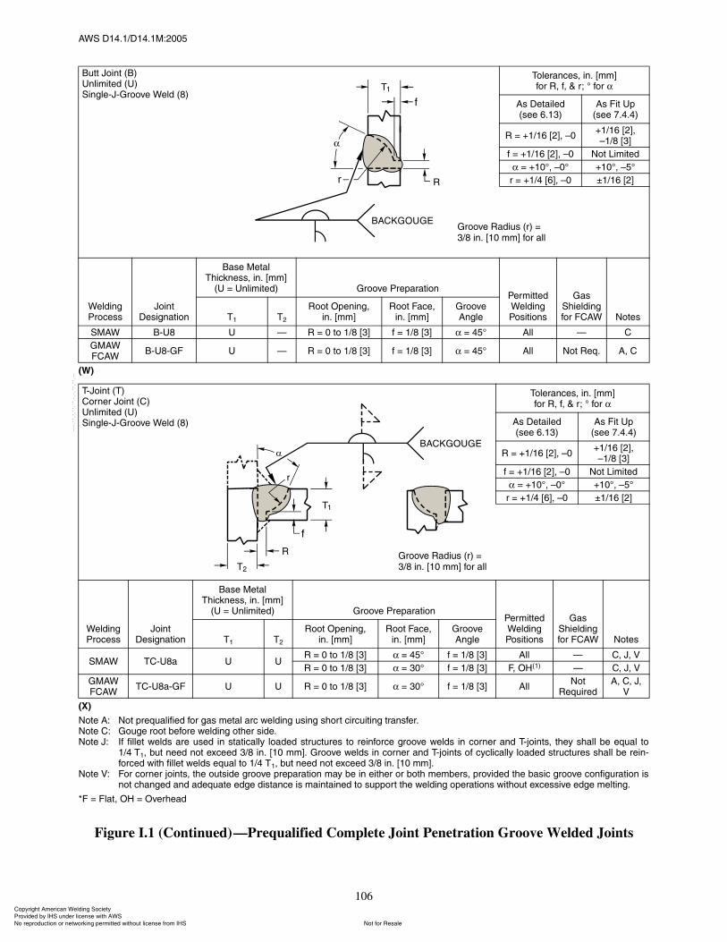
ßÉÍ ÜïìòïñÜïìòïÓæîððë
106
øÉ÷
øÈ÷
Ò±¬» ßæ Ò±¬ °®»¯«¿´·º·»¼ º±® ¹¿ ³»¬¿´ ¿®½ ©»´¼·²¹ «·²¹ ¸±®¬ ½·®½«·¬·²¹ ¬®¿²º»®òÒ±¬» Ýæ Ù±«¹» ®±±¬ ¾»º±®» ©»´¼·²¹ ±¬¸»® ·¼»òÒ±¬» Öæ ׺ º·´´»¬ ©»´¼ ¿®» «»¼ ·² ¬¿¬·½¿´´§ ´±¿¼»¼ ¬®«½¬«®» ¬± ®»·²º±®½» ¹®±±ª» ©»´¼ ·² ½±®²»® ¿²¼ Ì󶱷²¬ô ¬¸»§ ¸¿´´ ¾» »¯«¿´ ¬±
ïñì Ìïô ¾«¬ ²»»¼ ²±¬ »¨½»»¼ íñè ·²ò Åïð ³³Ãò Ù®±±ª» ©»´¼ ·² ½±®²»® ¿²¼ Ì󶱷²¬ ±º ½§½´·½¿´´§ ´±¿¼»¼ ¬®«½¬«®» ¸¿´´ ¾» ®»·²óº±®½»¼ ©·¬¸ º·´´»¬ ©»´¼ »¯«¿´ ¬± ïñì Ìïô ¾«¬ ²»»¼ ²±¬ »¨½»»¼ íñè ·²ò Åïð ³³Ãò
Ò±¬» Êæ Ú±® ½±®²»® ¶±·²¬ô ¬¸» ±«¬·¼» ¹®±±ª» °®»°¿®¿¬·±² ³¿§ ¾» ·² »·¬¸»® ±® ¾±¬¸ ³»³¾»®ô °®±ª·¼»¼ ¬¸» ¾¿·½ ¹®±±ª» ½±²º·¹«®¿¬·±² ·²±¬ ½¸¿²¹»¼ ¿²¼ ¿¼»¯«¿¬» »¼¹» ¼·¬¿²½» · ³¿·²¬¿·²»¼ ¬± «°°±®¬ ¬¸» ©»´¼·²¹ ±°»®¿¬·±² ©·¬¸±«¬ »¨½»·ª» »¼¹» ³»´¬·²¹ò
öÚ ã Ú´¿¬ô ÑØ ã Ѫ»®¸»¿¼
Figure I.1 (Continued)�Prequalified Complete Joint Penetration Groove Welded Joints
Þ«¬¬ Ö±·²¬ øÞ÷˲´·³·¬»¼ øË÷Í·²¹´»óÖóÙ®±±ª» É»´¼ øè÷
̱´»®¿²½»ô ·²ò ų³Ãº±® Îô ºô ú ®å p º±®
ß Ü»¬¿·´»¼ø»» êòïí÷
ß Ú·¬ Ë°ø»» éòìòì÷
Î ã õïñïê ÅîÃô �ðõïñïê ÅîÃô�ïñè ÅíÃ
º ã õïñïê ÅîÃô �ð Ò±¬ Ô·³·¬»¼
ã õïðpô �ðp õïðpô �ëp
® ã õïñì ÅêÃô �ð oïñïê ÅîÃ
É»´¼·²¹ Ю±½»
Ö±·²¬ Ü»·¹²¿¬·±²
Þ¿» Ó»¬¿´ ̸·½µ²»ô ·²ò ų³Ã
øË ã ˲´·³·¬»¼÷ Ù®±±ª» Ю»°¿®¿¬·±²Ð»®³·¬¬»¼ É»´¼·²¹ б·¬·±²
Ù¿ ͸·»´¼·²¹ º±® ÚÝßÉ Ò±¬»Ìï Ìî
ᱬ Ñ°»²·²¹ô·²ò ų³Ã
ᱬ Ú¿½»ô·²ò ų³Ã
Ù®±±ª» ß²¹´»
ÍÓßÉ ÞóËè Ë � Î ã 𠬱 ïñè Åíà º ã ïñè Åíà ã ìëp ß´´ � Ý
ÙÓßÉÚÝßÉ
ÞóËèóÙÚ Ë � Î ã 𠬱 ïñè Åíà º ã ïñè Åíà ã ìëp ß´´ Ò±¬ λ¯ò ßô Ý
ÌóÖ±·²¬ øÌ÷ݱ®²»® Ö±·²¬ øÝ÷˲´·³·¬»¼ øË÷Í·²¹´»óÖóÙ®±±ª» É»´¼ øè÷
̱´»®¿²½»ô ·²ò ų³Ãº±® Îô ºô ú ®å p º±®
ß Ü»¬¿·´»¼ø»» êòïí÷
ß Ú·¬ Ë°ø»» éòìòì÷
Î ã õïñïê ÅîÃô �ðõïñïê ÅîÃô�ïñè ÅíÃ
º ã õïñïê ÅîÃô �ð Ò±¬ Ô·³·¬»¼
ã õïðpô �ðp õïðpô �ëp
® ã õïñì ÅêÃô �ð oïñïê ÅîÃ
É»´¼·²¹ Ю±½»
Ö±·²¬ Ü»·¹²¿¬·±²
Þ¿» Ó»¬¿´ ̸·½µ²»ô ·²ò ų³Ã
øË ã ˲´·³·¬»¼÷ Ù®±±ª» Ю»°¿®¿¬·±²Ð»®³·¬¬»¼ É»´¼·²¹ б·¬·±²
Ù¿ ͸·»´¼·²¹ º±® ÚÝßÉ Ò±¬»Ìï Ìî
ᱬ Ñ°»²·²¹ô·²ò ų³Ã
ᱬ Ú¿½»ô·²ò ų³Ã
Ù®±±ª» ß²¹´»
ÍÓßÉ ÌÝóËè¿ Ë ËÎ ã 𠬱 ïñè Åíà ã ìëp º ã ïñè Åíà ߴ´ � Ýô Öô Ê
Î ã 𠬱 ïñè Åíà ã íðp º ã ïñè Åíà Úô ÑØøï÷ � Ýô Öô Ê
ÙÓßÉÚÝßÉ
ÌÝóËè¿óÙÚ Ë Ë Î ã 𠬱 ïñè Åíà ã íðp º ã ïñè Åíà ߴ´Ò±¬
λ¯«·®»¼ßô Ýô Öô
Ê
Ù®±±ª» ο¼·« ø®÷ ãíñè ·²ò Åï𠳳à º±® ¿´´
Ù®±±ª» ο¼·« ø®÷ ãíñè ·²ò Åï𠳳à º±® ¿´´
ݱ°§®·¹¸¬ ß³»®·½¿² É»´¼·²¹ ͱ½·»¬§ Ю±ª·¼»¼ ¾§ ×ØÍ «²¼»® ´·½»²» ©·¬¸ ßÉÍ
Ò±¬ º±® λ¿´»Ò± ®»°®±¼«½¬·±² ±® ²»¬©±®µ·²¹ °»®³·¬¬»¼ ©·¬¸±«¬ ´·½»²» º®±³ ×ØÍ
óóÀôôÀôôÀóÀóÀôôÀôôÀôÀôôÀóóó
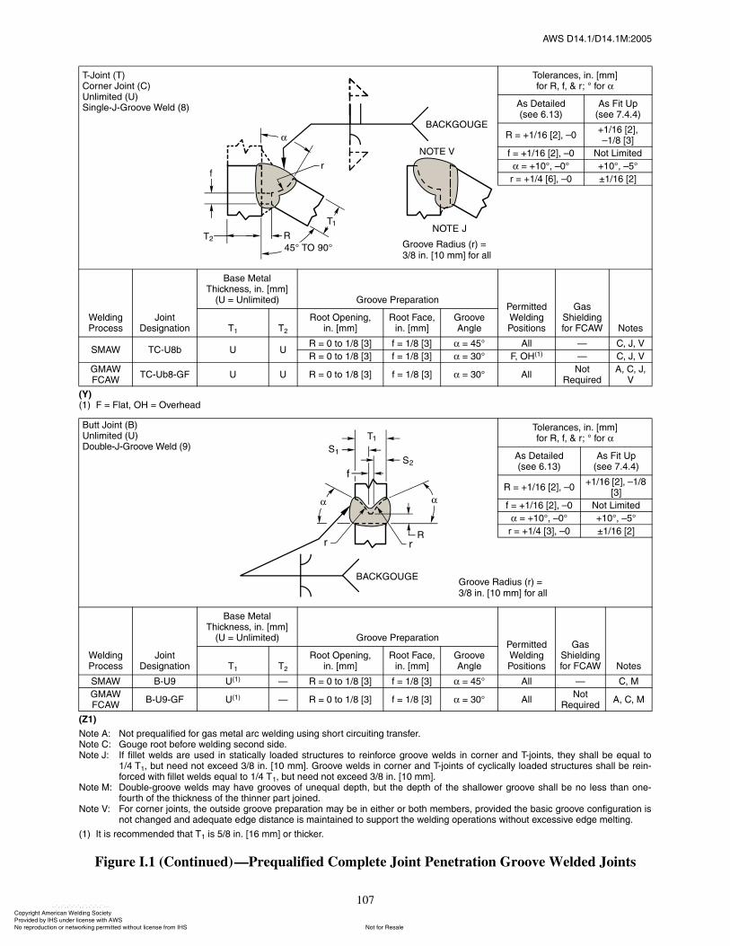
ßÉÍ ÜïìòïñÜïìòïÓæîððë
107
øÇ÷øï÷ Ú ã Ú´¿¬ô ÑØ ã Ѫ»®¸»¿¼
øÆï÷
Ò±¬» ßæ Ò±¬ °®»¯«¿´·º·»¼ º±® ¹¿ ³»¬¿´ ¿®½ ©»´¼·²¹ «·²¹ ¸±®¬ ½·®½«·¬·²¹ ¬®¿²º»®òÒ±¬» Ýæ Ù±«¹» ®±±¬ ¾»º±®» ©»´¼·²¹ »½±²¼ ·¼»òÒ±¬» Öæ ׺ º·´´»¬ ©»´¼ ¿®» «»¼ ·² ¬¿¬·½¿´´§ ´±¿¼»¼ ¬®«½¬«®» ¬± ®»·²º±®½» ¹®±±ª» ©»´¼ ·² ½±®²»® ¿²¼ Ì󶱷²¬ô ¬¸»§ ¸¿´´ ¾» »¯«¿´ ¬±
ïñì Ìïô ¾«¬ ²»»¼ ²±¬ »¨½»»¼ íñè ·²ò Åïð ³³Ãò Ù®±±ª» ©»´¼ ·² ½±®²»® ¿²¼ Ì󶱷²¬ ±º ½§½´·½¿´´§ ´±¿¼»¼ ¬®«½¬«®» ¸¿´´ ¾» ®»·²óº±®½»¼ ©·¬¸ º·´´»¬ ©»´¼ »¯«¿´ ¬± ïñì Ìïô ¾«¬ ²»»¼ ²±¬ »¨½»»¼ íñè ·²ò Åïð ³³Ãò
Ò±¬» Óæ ܱ«¾´»ó¹®±±ª» ©»´¼ ³¿§ ¸¿ª» ¹®±±ª» ±º «²»¯«¿´ ¼»°¬¸ô ¾«¬ ¬¸» ¼»°¬¸ ±º ¬¸» ¸¿´´±©»® ¹®±±ª» ¸¿´´ ¾» ²± ´» ¬¸¿² ±²»óº±«®¬¸ ±º ¬¸» ¬¸·½µ²» ±º ¬¸» ¬¸·²²»® °¿®¬ ¶±·²»¼ò
Ò±¬» Êæ Ú±® ½±®²»® ¶±·²¬ô ¬¸» ±«¬·¼» ¹®±±ª» °®»°¿®¿¬·±² ³¿§ ¾» ·² »·¬¸»® ±® ¾±¬¸ ³»³¾»®ô °®±ª·¼»¼ ¬¸» ¾¿·½ ¹®±±ª» ½±²º·¹«®¿¬·±² ·²±¬ ½¸¿²¹»¼ ¿²¼ ¿¼»¯«¿¬» »¼¹» ¼·¬¿²½» · ³¿·²¬¿·²»¼ ¬± «°°±®¬ ¬¸» ©»´¼·²¹ ±°»®¿¬·±² ©·¬¸±«¬ »¨½»·ª» »¼¹» ³»´¬·²¹ò
øï÷ ׬ · ®»½±³³»²¼»¼ ¬¸¿¬ Ìï · ëñè ·²ò Åïê ³³Ã ±® ¬¸·½µ»®ò
Figure I.1 (Continued)�Prequalified Complete Joint Penetration Groove Welded Joints
ÌóÖ±·²¬ øÌ÷ݱ®²»® Ö±·²¬ øÝ÷˲´·³·¬»¼ øË÷Í·²¹´»óÖóÙ®±±ª» É»´¼ øè÷
̱´»®¿²½»ô ·²ò ų³Ãº±® Îô ºô ú ®å p º±®
ß Ü»¬¿·´»¼ø»» êòïí÷
ß Ú·¬ Ë°ø»» éòìòì÷
Î ã õïñïê ÅîÃô �ðõïñïê ÅîÃô�ïñè ÅíÃ
º ã õïñïê ÅîÃô �ð Ò±¬ Ô·³·¬»¼
ã õïðpô �ðp õïðpô �ëp
® ã õïñì ÅêÃô �ð oïñïê ÅîÃ
É»´¼·²¹ Ю±½»
Ö±·²¬ Ü»·¹²¿¬·±²
Þ¿» Ó»¬¿´ ̸·½µ²»ô ·²ò ų³Ã
øË ã ˲´·³·¬»¼÷ Ù®±±ª» Ю»°¿®¿¬·±²Ð»®³·¬¬»¼ É»´¼·²¹ б·¬·±²
Ù¿ ͸·»´¼·²¹ º±® ÚÝßÉ Ò±¬»Ìï Ìî
ᱬ Ñ°»²·²¹ô·²ò ų³Ã
ᱬ Ú¿½»ô·²ò ų³Ã
Ù®±±ª» ß²¹´»
ÍÓßÉ ÌÝóËè¾ Ë ËÎ ã 𠬱 ïñè Åíà º ã ïñè Åíà ã ìëp ß´´ � Ýô Öô Ê
Î ã 𠬱 ïñè Åíà º ã ïñè Åíà ã íðp Úô ÑØøï÷ � Ýô Öô Ê
ÙÓßÉÚÝßÉ
ÌÝó˾èóÙÚ Ë Ë Î ã 𠬱 ïñè Åíà ߴ´Ò±¬
λ¯«·®»¼ßô Ýô Öô
ʺ ã ïñè Åíà ã íðp
Þ«¬¬ Ö±·²¬ øÞ÷˲´·³·¬»¼ øË÷ܱ«¾´»óÖóÙ®±±ª» É»´¼ øç÷
̱´»®¿²½»ô ·²ò ų³Ãº±® Îô ºô ú ®å p º±®
ß Ü»¬¿·´»¼ø»» êòïí÷
ß Ú·¬ Ë°ø»» éòìòì÷
Î ã õïñïê ÅîÃô �ðõïñïê ÅîÃô �ïñè
ÅíÃ
º ã õïñïê ÅîÃô �ð Ò±¬ Ô·³·¬»¼
ã õïðpô �ðp õïðpô �ëp
® ã õïñì ÅíÃô �ð oïñïê ÅîÃ
É»´¼·²¹ Ю±½»
Ö±·²¬ Ü»·¹²¿¬·±²
Þ¿» Ó»¬¿´ ̸·½µ²»ô ·²ò ų³Ã
øË ã ˲´·³·¬»¼÷ Ù®±±ª» Ю»°¿®¿¬·±²Ð»®³·¬¬»¼ É»´¼·²¹ б·¬·±²
Ù¿ ͸·»´¼·²¹ º±® ÚÝßÉ Ò±¬»Ìï Ìî
ᱬ Ñ°»²·²¹ô·²ò ų³Ã
ᱬ Ú¿½»ô·²ò ų³Ã
Ù®±±ª» ß²¹´»
ÍÓßÉ ÞóËç Ëøï÷ � Î ã 𠬱 ïñè Åíà º ã ïñè Åíà ã ìëp ß´´ � Ýô Ó
ÙÓßÉÚÝßÉ
ÞóËçóÙÚ Ëøï÷ � Î ã 𠬱 ïñè Åíà º ã ïñè Åíà ã íðp ß´´Ò±¬
λ¯«·®»¼ßô Ýô Ó
Ù®±±ª» ο¼·« ø®÷ ãíñè ·²ò Åï𠳳à º±® ¿´´
Ù®±±ª» ο¼·« ø®÷ ãíñè ·²ò Åï𠳳à º±® ¿´´
ݱ°§®·¹¸¬ ß³»®·½¿² É»´¼·²¹ ͱ½·»¬§ Ю±ª·¼»¼ ¾§ ×ØÍ «²¼»® ´·½»²» ©·¬¸ ßÉÍ
Ò±¬ º±® λ¿´»Ò± ®»°®±¼«½¬·±² ±® ²»¬©±®µ·²¹ °»®³·¬¬»¼ ©·¬¸±«¬ ´·½»²» º®±³ ×ØÍ
óóÀôôÀôôÀóÀóÀôôÀôôÀôÀôôÀóóó
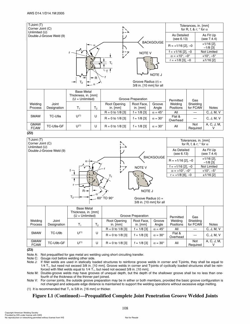
ßÉÍ ÜïìòïñÜïìòïÓæîððë
108
øÆî÷
øÆí÷
Ò±¬» ßæ Ò±¬ °®»¯«¿´·º·»¼ º±® ¹¿ ³»¬¿´ ¿®½ ©»´¼·²¹ «·²¹ ¸±®¬ ½·®½«·¬·²¹ ¬®¿²º»®òÒ±¬» Ýæ Ù±«¹» ®±±¬ ¾»º±®» ©»´¼·²¹ ±¬¸»® ·¼»òÒ±¬» Öæ ׺ º·´´»¬ ©»´¼ ¿®» «»¼ ·² ¬¿¬·½¿´´§ ´±¿¼»¼ ¬®«½¬«®» ¬± ®»·²º±®½» ¹®±±ª» ©»´¼ ·² ½±®²»® ¿²¼ Ì󶱷²¬ô ¬¸»§ ¸¿´´ ¾» »¯«¿´ ¬±
ïñì Ìïô ¾«¬ ²»»¼ ²±¬ »¨½»»¼ íñè ·²ò Åïð ³³Ãò Ù®±±ª» ©»´¼ ·² ½±®²»® ¿²¼ Ì󶱷²¬ ±º ½§½´·½¿´´§ ´±¿¼»¼ ¬®«½¬«®» ¸¿´´ ¾» ®»·²óº±®½»¼ ©·¬¸ º·´´»¬ ©»´¼ »¯«¿´ ¬± ïñì Ìïô ¾«¬ ²»»¼ ²±¬ »¨½»»¼ íñè ·²ò Åïð ³³Ãò
Ò±¬» Óæ ܱ«¾´»ó¹®±±ª» ©»´¼ ³¿§ ¸¿ª» ¹®±±ª» ±º «²»¯«¿´ ¼»°¬¸ô ¾«¬ ¬¸» ¼»°¬¸ ±º ¬¸» ¸¿´´±©»® ¹®±±ª» ¸¿´´ ¾» ²± ´» ¬¸¿² ±²»óº±«®¬¸ ±º ¬¸» ¬¸·½µ²» ±º ¬¸» ¬¸·²²»® °¿®¬ ¶±·²»¼ò
Ò±¬» Êæ Ú±® ½±®²»® ¶±·²¬ô ¬¸» ±«¬·¼» ¹®±±ª» °®»°¿®¿¬·±² ³¿§ ¾» ·² »·¬¸»® ±® ¾±¬¸ ³»³¾»®ô °®±ª·¼»¼ ¬¸» ¾¿·½ ¹®±±ª» ½±²º·¹«®¿¬·±² ·²±¬ ½¸¿²¹»¼ ¿²¼ ¿¼»¯«¿¬» »¼¹» ¼·¬¿²½» · ³¿·²¬¿·²»¼ ¬± «°°±®¬ ¬¸» ©»´¼·²¹ ±°»®¿¬·±² ©·¬¸±«¬ »¨½»·ª» »¼¹» ³»´¬·²¹ò
øï÷ ׬ · ®»½±³³»²¼»¼ ¬¸¿¬ Ìï · ëñè ·²ò Åïê ³³Ã ±® ¬¸·½µ»®ò
Figure I.1 (Continued)�Prequalified Complete Joint Penetration Groove Welded Joints
ÌóÖ±·²¬ øÌ÷ݱ®²»® Ö±·²¬ øÝ÷˲´·³·¬»¼ øË÷ܱ«¾´»óÖóÙ®±±ª» É»´¼ øç÷
̱´»®¿²½»ô ·²ò ų³Ãº±® Îô ºô ú ®å p º±®
ß Ü»¬¿·´»¼ø»» êòïí÷
ß Ú·¬ Ë°ø»» éòìòì÷
Î ã õïñïê ÅîÃô �ðõïñïê ÅîÃô�ïñè ÅíÃ
º ã õïñïê ÅîÃô �ð Ò±¬ Ô·³·¬»¼
ã õïðpô �ðp õïðpô �ëp
® ã õïñè ÅíÃô �ð oïñïê ÅîÃ
É»´¼·²¹ Ю±½»
Ö±·²¬ Ü»·¹²¿¬·±²
Þ¿» Ó»¬¿´ ̸·½µ²»ô ·²ò ų³Ã
øË ã ˲´·³·¬»¼÷ Ù®±±ª» Ю»°¿®¿¬·±² л®³·¬¬»¼ É»´¼·²¹ б·¬·±²
Ù¿ ͸·»´¼·²¹ º±® ÚÝßÉ Ò±¬»Ìï Ìî
ᱬ Ñ°»²·²¹·²ò ų³Ã
ᱬ Ú¿½»ô·²ò ų³Ã
Ù®±±ª» ß²¹´»
ÍÓßÉ ÌÝóËç¿ Ëøï÷ Ë
Î ã 𠬱 ïñè Åíà º ã ïñè Åíà ã ìëp ß´´ � Ýô Öô Óô Ê
Î ã 𠬱 ïñè Åíà º ã ïñè Åíà ã íðpÚ´¿¬ ú
Ѫ»®¸»¿¼� Ýô Öô Óô Ê
ÙÓßÉÚÝßÉ
ÌÝóËç¿óÙÚ Ëøï÷ Ë Î ã 𠬱 ïñè Åíà ã íðp ß´´Ò±¬
λ¯«·®»¼ßô Ýô Öô Óô
ʺ ã ïñè ÅíÃ
ÌóÖ±·²¬ øÌ÷ݱ®²»® Ö±·²¬ øÝ÷˲´·³·¬»¼ øË÷ܱ«¾´»óÖóÙ®±±ª» É»´¼ øç÷
̱´»®¿²½»ô ·²ò ų³Ãº±® Îô ºô ú ®å p º±®
ß Ü»¬¿·´»¼ø»» êòïí÷
ß Ú·¬ Ë°ø»» éòìòì÷
Î ã õïñïê ÅîÃô �ðõïñïê ÅîÃô�ïñè ÅíÃ
º ã õïñïê ÅîÃô �ð Ò±¬ Ô·³·¬»¼
ã õïðpô �ðp õïðpô �ëp
® ã õïñè ÅêÃô �ð oïñïê ÅîÃ
É»´¼·²¹ Ю±½»
Ö±·²¬ Ü»·¹²¿¬·±²
Þ¿» Ó»¬¿´ ̸·½µ²»ô ·²ò ų³Ã
øË ã ˲´·³·¬»¼÷ Ù®±±ª» Ю»°¿®¿¬·±² л®³·¬¬»¼ É»´¼·²¹ б·¬·±²
Ù¿ ͸·»´¼·²¹ º±® ÚÝßÉ Ò±¬»Ìï Ìî
ᱬ Ñ°»²·²¹·²ò ų³Ã
ᱬ Ú¿½»ô·²ò ų³Ã
Ù®±±ª» ß²¹´»
ÍÓßÉ ÌÝóËç¾ Ëøï÷ Ë
Î ã 𠬱 ïñè Åíà º ã ïñè Åíà ã ìëp ß´´ � Ýô Öô Óô Ê
Î ã 𠬱 ïñè Åíà º ã ïñè Åíà ã íðpÚ´¿¬ ú
Ѫ»®¸»¿¼� Ýô Öô Óô Ê
ÙÓßÉÚÝßÉ
ÌÝóËç¾óÙÚ Ëøï÷ Ë Î ã 𠬱 ïñè Åíà ã íðp ß´´Ò±¬
λ¯«·®»¼ßô Ýô Öô Óô
ʺ ã ïñè ÅíÃ
Ù®±±ª» ο¼·« ø®÷ ãíñè ·²ò Åï𠳳à º±® ¿´´
Ù®±±ª» ο¼·« ø®÷ ãíñè ·²ò Åï𠳳à º±® ¿´´
ݱ°§®·¹¸¬ ß³»®·½¿² É»´¼·²¹ ͱ½·»¬§ Ю±ª·¼»¼ ¾§ ×ØÍ «²¼»® ´·½»²» ©·¬¸ ßÉÍ
Ò±¬ º±® λ¿´»Ò± ®»°®±¼«½¬·±² ±® ²»¬©±®µ·²¹ °»®³·¬¬»¼ ©·¬¸±«¬ ´·½»²» º®±³ ×ØÍ
óóÀôôÀôôÀóÀóÀôôÀôôÀôÀôôÀóóó

ßÉÍ ÜïìòïñÜïìòïÓæîððë
109
øß÷
øÞ÷
Ò±¬» Þæ Ö±·²¬ ©»´¼»¼ º®±³ ±²» ·¼»òÒ±¬» Ýîæ ᱬ ²»»¼ ²±¬ ¾» ¹±«¹»¼ ¾»º±®» ©»´¼·²¹ ±¬¸»® ·¼»òÒ±¬» Ûæ Ó·²·³«³ »ºº»½¬·ª» ¬¸®±¿¬ ¿ ¬¿¬»¼ ·² Ì¿¾´» ëò
Figure I.2�Prequalified Partial Joint Penetration Groove Welded Joints
Þ«¬¬ Ö±·²¬ øÞ÷ﮬ·¿´ л²»¬®¿¬·±² øÐ÷ͯ«¿®»óÙ®±±ª» É»´¼ øï÷
É»´¼·²¹ Ю±½»
Ö±·²¬ Ü»·¹²¿¬·±²
Þ¿» Ó»¬¿´ ̸·½µ²»ô ·²ò ų³Ã
øË ã ˲´·³·¬»¼÷
Ù®±±ª» Ю»°¿®¿¬·±²
л®³·¬¬»¼ É»´¼·²¹ б·¬·±²
Ûºº»½¬·ª» ̸®±¿¬ øÛ÷ô
·²ò ų³Ã Ò±¬»Î±±¬ Ñ°»²·²¹ô
·²ò ų³Ã
̱´»®¿²½»ô ·²ò ų³Ã
Ìï Ìî
ß Ü»¬¿·´»¼ø»» êòïí÷
ß Ú·¬ Ë°ø»» éòìòì÷
ÍÓßÉ
ÞóÐï¿ ïñè Åíà � Î ã 𠬱 ïñïê Åîà õïñïê ÅîÃô �ð oïñïê Åîà ߴ´ Ìï � ïñíî Åïà Þ
ÞóÐï½ ïñì Åêà ³¿¨ � Î ã ³·²·³«³ õïñïê ÅîÃô �ð oïñïê Åîà ߴ´ Þô Û
Þ«¬¬ Ö±·²¬ øÞ÷ﮬ·¿´ л²»¬®¿¬·±² øÐ÷ͯ«¿®»óÙ®±±ª» É»´¼ øï÷
É»´¼·²¹ Ю±½»
Ö±·²¬ Ü»·¹²¿¬·±²
Þ¿» Ó»¬¿´ ̸·½µ²»ô ·²ò
ų³ÃøË ã ˲´·³·¬»¼÷
Ù®±±ª» Ю»°¿®¿¬·±²
л®³·¬¬»¼ É»´¼·²¹ б·¬·±²
Ûºº»½¬·ª» ̸®±¿¬ øÛ÷ô
·²ò ų³Ã Ò±¬»Î±±¬ Ñ°»²·²¹ô
·²ò ų³Ã
̱´»®¿²½»ô ·²ò ų³Ã
Ìï Ìî
ß Ü»¬¿·´»¼ø»» êòïí÷
ß Ú·¬ Ë°ø»» éòìòì÷
ÍÓßÉ ÞóÐï¾ ïñì Åêà ³¿¨ � Î ã ³·²·³«³ õïñïê ÅîÃô �ð oïñïê Åîà ߴ´ Ýîô Û
Ìï
îóóóóóó
Ìï
î------
Ìï
îóóóóóó
íÌï
ì----------
ݱ°§®·¹¸¬ ß³»®·½¿² É»´¼·²¹ ͱ½·»¬§ Ю±ª·¼»¼ ¾§ ×ØÍ «²¼»® ´·½»²» ©·¬¸ ßÉÍ
Ò±¬ º±® λ¿´»Ò± ®»°®±¼«½¬·±² ±® ²»¬©±®µ·²¹ °»®³·¬¬»¼ ©·¬¸±«¬ ´·½»²» º®±³ ×ØÍ
óóÀôôÀôôÀóÀóÀôôÀôôÀôÀôôÀóóó
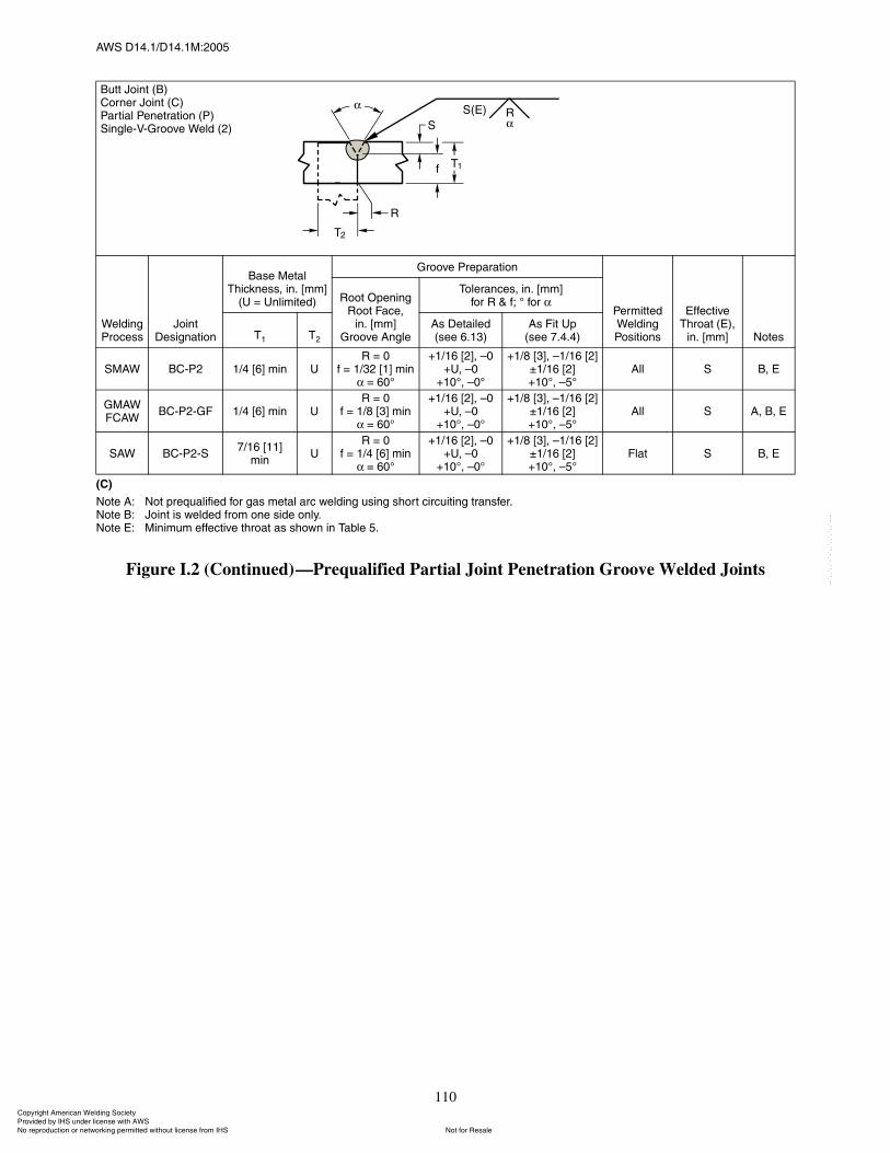
ßÉÍ ÜïìòïñÜïìòïÓæîððë
110
øÝ÷
Ò±¬» ßæ Ò±¬ °®»¯«¿´·º·»¼ º±® ¹¿ ³»¬¿´ ¿®½ ©»´¼·²¹ «·²¹ ¸±®¬ ½·®½«·¬·²¹ ¬®¿²º»®òÒ±¬» Þæ Ö±·²¬ · ©»´¼»¼ º®±³ ±²» ·¼» ±²´§òÒ±¬» Ûæ Ó·²·³«³ »ºº»½¬·ª» ¬¸®±¿¬ ¿ ¸±©² ·² Ì¿¾´» ëò
Figure I.2 (Continued)�Prequalified Partial Joint Penetration Groove Welded Joints
Þ«¬¬ Ö±·²¬ øÞ÷ݱ®²»® Ö±·²¬ øÝ÷ﮬ·¿´ л²»¬®¿¬·±² øÐ÷Í·²¹´»óÊóÙ®±±ª» É»´¼ øî÷
É»´¼·²¹ Ю±½»
Ö±·²¬ Ü»·¹²¿¬·±²
Þ¿» Ó»¬¿´ ̸·½µ²»ô ·²ò ų³Ã
øË ã ˲´·³·¬»¼÷
Ù®±±ª» Ю»°¿®¿¬·±²
л®³·¬¬»¼ É»´¼·²¹ б·¬·±²
Ûºº»½¬·ª» ̸®±¿¬ øÛ÷ô
·²ò ų³Ã Ò±¬»
ᱬ Ñ°»²·²¹Î±±¬ Ú¿½»ô
·²ò ų³ÃÙ®±±ª» ß²¹´»
̱´»®¿²½»ô ·²ò ų³Ãº±® Î ú ºå p º±®
Ìï Ìî
ß Ü»¬¿·´»¼ø»» êòïí÷
ß Ú·¬ Ë°ø»» éòìòì÷
ÍÓßÉ ÞÝóÐî ïñì Åêà ³·² ËÎ ã ð
º ã ïñíî Åïà ³·²ã êðp
õïñïê ÅîÃô �ðõËô �ð
õïðpô �ðp
õïñè ÅíÃô �ïñïê ÅîÃoïñïê ÅîÃõïðpô �ëp
ß´´ Í Þô Û
ÙÓßÉÚÝßÉ
ÞÝóÐîóÙÚ ïñì Åêà ³·² ËÎ ã ð
º ã ïñè Åíà ³·²ã êðp
õïñïê ÅîÃô �ðõËô �ð
õïðpô �ðp
õïñè ÅíÃô �ïñïê ÅîÃoïñïê ÅîÃõïðpô �ëp
ß´´ Í ßô Þô Û
ÍßÉ ÞÝóÐîóÍéñïê ÅïïÃ
³·²Ë
Î ã ðº ã ïñì Åêà ³·²
ã êðp
õïñïê ÅîÃô �ðõËô �ð
õïðpô �ðp
õïñè ÅíÃô �ïñïê ÅîÃoïñïê ÅîÃõïðpô �ëp
Ú´¿¬ Í Þô Û
ݱ°§®·¹¸¬ ß³»®·½¿² É»´¼·²¹ ͱ½·»¬§ Ю±ª·¼»¼ ¾§ ×ØÍ «²¼»® ´·½»²» ©·¬¸ ßÉÍ
Ò±¬ º±® λ¿´»Ò± ®»°®±¼«½¬·±² ±® ²»¬©±®µ·²¹ °»®³·¬¬»¼ ©·¬¸±«¬ ´·½»²» º®±³ ×ØÍ
óóÀôôÀôôÀóÀóÀôôÀôôÀôÀôôÀóóó
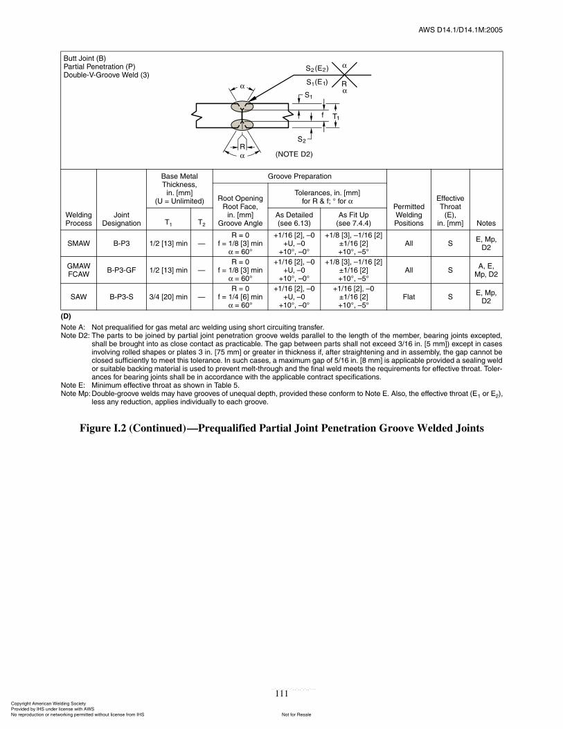
ßÉÍ ÜïìòïñÜïìòïÓæîððë
111
øÜ÷
Ò±¬» ßæ Ò±¬ °®»¯«¿´·º·»¼ º±® ¹¿ ³»¬¿´ ¿®½ ©»´¼·²¹ «·²¹ ¸±®¬ ½·®½«·¬·²¹ ¬®¿²º»®òÒ±¬» Üîæ ̸» °¿®¬ ¬± ¾» ¶±·²»¼ ¾§ °¿®¬·¿´ ¶±·²¬ °»²»¬®¿¬·±² ¹®±±ª» ©»´¼ °¿®¿´´»´ ¬± ¬¸» ´»²¹¬¸ ±º ¬¸» ³»³¾»®ô ¾»¿®·²¹ ¶±·²¬ »¨½»°¬»¼ô
¸¿´´ ¾» ¾®±«¹¸¬ ·²¬± ¿ ½´±» ½±²¬¿½¬ ¿ °®¿½¬·½¿¾´»ò ̸» ¹¿° ¾»¬©»»² °¿®¬ ¸¿´´ ²±¬ »¨½»»¼ íñïê ·²ò Åë ³³Ã÷ »¨½»°¬ ·² ½¿»·²ª±´ª·²¹ ®±´´»¼ ¸¿°» ±® °´¿¬» í ·²ò Åéë ³³Ã ±® ¹®»¿¬»® ·² ¬¸·½µ²» ·ºô ¿º¬»® ¬®¿·¹¸¬»²·²¹ ¿²¼ ·² ¿»³¾´§ô ¬¸» ¹¿° ½¿²²±¬ ¾»½´±»¼ «ºº·½·»²¬´§ ¬± ³»»¬ ¬¸· ¬±´»®¿²½»ò ײ «½¸ ½¿»ô ¿ ³¿¨·³«³ ¹¿° ±º ëñïê ·²ò Åè ³³Ã · ¿°°´·½¿¾´» °®±ª·¼»¼ ¿ »¿´·²¹ ©»´¼±® «·¬¿¾´» ¾¿½µ·²¹ ³¿¬»®·¿´ · «»¼ ¬± °®»ª»²¬ ³»´¬ó¬¸®±«¹¸ ¿²¼ ¬¸» º·²¿´ ©»´¼ ³»»¬ ¬¸» ®»¯«·®»³»²¬ º±® »ºº»½¬·ª» ¬¸®±¿¬ò ̱´»®ó¿²½» º±® ¾»¿®·²¹ ¶±·²¬ ¸¿´´ ¾» ·² ¿½½±®¼¿²½» ©·¬¸ ¬¸» ¿°°´·½¿¾´» ½±²¬®¿½¬ °»½·º·½¿¬·±²ò
Ò±¬» Ûæ Ó·²·³«³ »ºº»½¬·ª» ¬¸®±¿¬ ¿ ¸±©² ·² Ì¿¾´» ëòÒ±¬» Ó°æ ܱ«¾´»ó¹®±±ª» ©»´¼ ³¿§ ¸¿ª» ¹®±±ª» ±º «²»¯«¿´ ¼»°¬¸ô °®±ª·¼»¼ ¬¸»» ½±²º±®³ ¬± Ò±¬» Ûò ß´±ô ¬¸» »ºº»½¬·ª» ¬¸®±¿¬ øÛï ±® Ûî÷ô
´» ¿²§ ®»¼«½¬·±²ô ¿°°´·» ·²¼·ª·¼«¿´´§ ¬± »¿½¸ ¹®±±ª»ò
Figure I.2 (Continued)�Prequalified Partial Joint Penetration Groove Welded Joints
Þ«¬¬ Ö±·²¬ øÞ÷ﮬ·¿´ л²»¬®¿¬·±² øÐ÷ܱ«¾´»óÊóÙ®±±ª» É»´¼ øí÷
É»´¼·²¹ Ю±½»
Ö±·²¬ Ü»·¹²¿¬·±²
Þ¿» Ó»¬¿´ ̸·½µ²»ô
·²ò ų³ÃøË ã ˲´·³·¬»¼÷
Ù®±±ª» Ю»°¿®¿¬·±²
л®³·¬¬»¼ É»´¼·²¹ б·¬·±²
Ûºº»½¬·ª» ̸®±¿¬
øÛ÷ô·²ò ų³Ã Ò±¬»
ᱬ Ñ°»²·²¹Î±±¬ Ú¿½»ô
·²ò ų³ÃÙ®±±ª» ß²¹´»
̱´»®¿²½»ô ·²ò ų³Ãº±® Î ú ºå p º±®
Ìï Ìî
ß Ü»¬¿·´»¼ø»» êòïí÷
ß Ú·¬ Ë°ø»» éòìòì÷
ÍÓßÉ ÞóÐí ïñî Åïíà ³·² �Î ã ð
º ã ïñè Åíà ³·²ã êðp
õïñïê ÅîÃô �ðõËô �ð
õïðpô �ðp
õïñè ÅíÃô �ïñïê ÅîÃoïñïê ÅîÃõïðpô �ëp
ß´´ ÍÛô Ó°ô
Üî
ÙÓßÉÚÝßÉ
ÞóÐíóÙÚ ïñî Åïíà ³·² �Î ã ð
º ã ïñè Åíà ³·²ã êðp
õïñïê ÅîÃô �ðõËô �ð
õïðpô �ðp
õïñè ÅíÃô �ïñïê ÅîÃoïñïê ÅîÃõïðpô �ëp
ß´´ Íßô Ûô
Ó°ô Üî
ÍßÉ ÞóÐíóÍ íñì Åîðà ³·² �Î ã ð
º ã ïñì Åêà ³·²ã êðp
õïñïê ÅîÃô �ðõËô �ð
õïðpô �ðp
õïñïê ÅîÃô �ðoïñïê ÅîÃõïðpô �ëp
Ú´¿¬ ÍÛô Ó°ô
Üî
ݱ°§®·¹¸¬ ß³»®·½¿² É»´¼·²¹ ͱ½·»¬§ Ю±ª·¼»¼ ¾§ ×ØÍ «²¼»® ´·½»²» ©·¬¸ ßÉÍ
Ò±¬ º±® λ¿´»Ò± ®»°®±¼«½¬·±² ±® ²»¬©±®µ·²¹ °»®³·¬¬»¼ ©·¬¸±«¬ ´·½»²» º®±³ ×ØÍ
óóÀôôÀôôÀóÀóÀôôÀôôÀôÀôôÀóóó
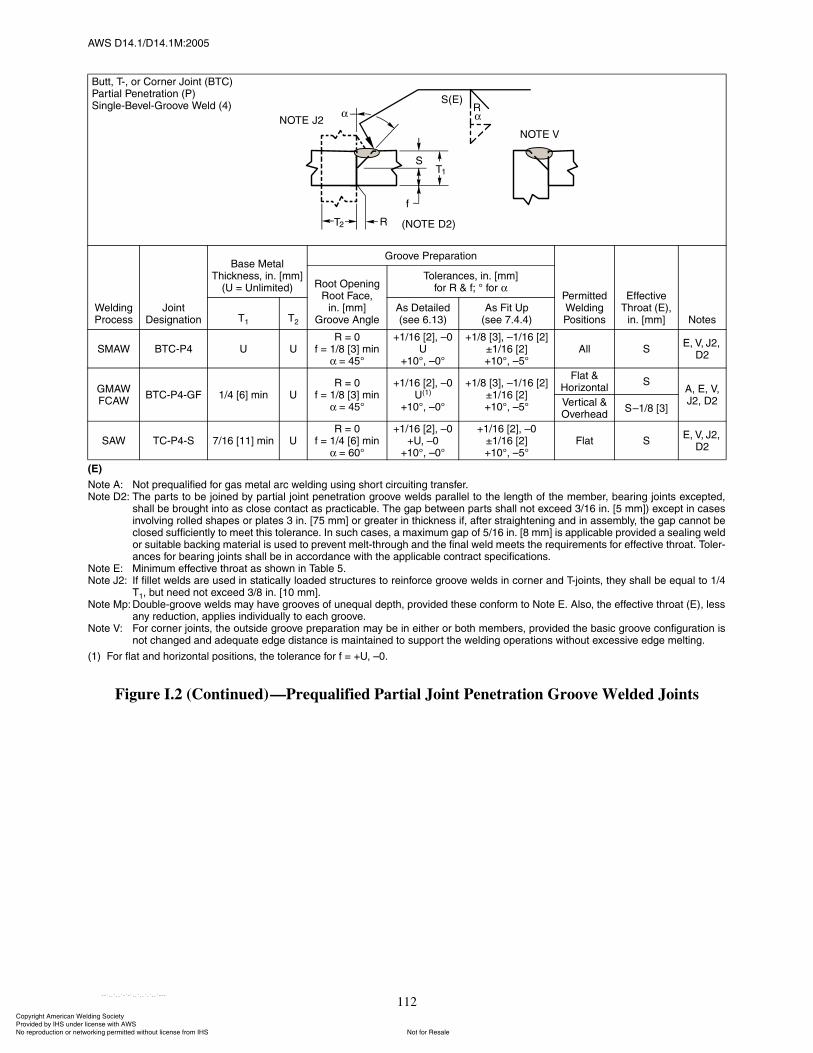
ßÉÍ ÜïìòïñÜïìòïÓæîððë
112
øÛ÷
Ò±¬» ßæ Ò±¬ °®»¯«¿´·º·»¼ º±® ¹¿ ³»¬¿´ ¿®½ ©»´¼·²¹ «·²¹ ¸±®¬ ½·®½«·¬·²¹ ¬®¿²º»®òÒ±¬» Üîæ ̸» °¿®¬ ¬± ¾» ¶±·²»¼ ¾§ °¿®¬·¿´ ¶±·²¬ °»²»¬®¿¬·±² ¹®±±ª» ©»´¼ °¿®¿´´»´ ¬± ¬¸» ´»²¹¬¸ ±º ¬¸» ³»³¾»®ô ¾»¿®·²¹ ¶±·²¬ »¨½»°¬»¼ô
¸¿´´ ¾» ¾®±«¹¸¬ ·²¬± ¿ ½´±» ½±²¬¿½¬ ¿ °®¿½¬·½¿¾´»ò ̸» ¹¿° ¾»¬©»»² °¿®¬ ¸¿´´ ²±¬ »¨½»»¼ íñïê ·²ò Åë ³³Ã÷ »¨½»°¬ ·² ½¿»·²ª±´ª·²¹ ®±´´»¼ ¸¿°» ±® °´¿¬» í ·²ò Åéë ³³Ã ±® ¹®»¿¬»® ·² ¬¸·½µ²» ·ºô ¿º¬»® ¬®¿·¹¸¬»²·²¹ ¿²¼ ·² ¿»³¾´§ô ¬¸» ¹¿° ½¿²²±¬ ¾»½´±»¼ «ºº·½·»²¬´§ ¬± ³»»¬ ¬¸· ¬±´»®¿²½»ò ײ «½¸ ½¿»ô ¿ ³¿¨·³«³ ¹¿° ±º ëñïê ·²ò Åè ³³Ã · ¿°°´·½¿¾´» °®±ª·¼»¼ ¿ »¿´·²¹ ©»´¼±® «·¬¿¾´» ¾¿½µ·²¹ ³¿¬»®·¿´ · «»¼ ¬± °®»ª»²¬ ³»´¬ó¬¸®±«¹¸ ¿²¼ ¬¸» º·²¿´ ©»´¼ ³»»¬ ¬¸» ®»¯«·®»³»²¬ º±® »ºº»½¬·ª» ¬¸®±¿¬ò ̱´»®ó¿²½» º±® ¾»¿®·²¹ ¶±·²¬ ¸¿´´ ¾» ·² ¿½½±®¼¿²½» ©·¬¸ ¬¸» ¿°°´·½¿¾´» ½±²¬®¿½¬ °»½·º·½¿¬·±²ò
Ò±¬» Ûæ Ó·²·³«³ »ºº»½¬·ª» ¬¸®±¿¬ ¿ ¸±©² ·² Ì¿¾´» ëòÒ±¬» Öîæ ׺ º·´´»¬ ©»´¼ ¿®» «»¼ ·² ¬¿¬·½¿´´§ ´±¿¼»¼ ¬®«½¬«®» ¬± ®»·²º±®½» ¹®±±ª» ©»´¼ ·² ½±®²»® ¿²¼ Ì󶱷²¬ô ¬¸»§ ¸¿´´ ¾» »¯«¿´ ¬± ïñì
Ìïô ¾«¬ ²»»¼ ²±¬ »¨½»»¼ íñè ·²ò Åïð ³³ÃòÒ±¬» Ó°æ ܱ«¾´»ó¹®±±ª» ©»´¼ ³¿§ ¸¿ª» ¹®±±ª» ±º «²»¯«¿´ ¼»°¬¸ô °®±ª·¼»¼ ¬¸»» ½±²º±®³ ¬± Ò±¬» Ûò ß´±ô ¬¸» »ºº»½¬·ª» ¬¸®±¿¬ øÛ÷ô ´»
¿²§ ®»¼«½¬·±²ô ¿°°´·» ·²¼·ª·¼«¿´´§ ¬± »¿½¸ ¹®±±ª»òÒ±¬» Êæ Ú±® ½±®²»® ¶±·²¬ô ¬¸» ±«¬·¼» ¹®±±ª» °®»°¿®¿¬·±² ³¿§ ¾» ·² »·¬¸»® ±® ¾±¬¸ ³»³¾»®ô °®±ª·¼»¼ ¬¸» ¾¿·½ ¹®±±ª» ½±²º·¹«®¿¬·±² ·
²±¬ ½¸¿²¹»¼ ¿²¼ ¿¼»¯«¿¬» »¼¹» ¼·¬¿²½» · ³¿·²¬¿·²»¼ ¬± «°°±®¬ ¬¸» ©»´¼·²¹ ±°»®¿¬·±² ©·¬¸±«¬ »¨½»·ª» »¼¹» ³»´¬·²¹ò
øï÷ Ú±® º´¿¬ ¿²¼ ¸±®·¦±²¬¿´ °±·¬·±²ô ¬¸» ¬±´»®¿²½» º±® º ã õËô �ðò
Figure I.2 (Continued)�Prequalified Partial Joint Penetration Groove Welded Joints
Þ«¬¬ô Ìóô ±® ݱ®²»® Ö±·²¬ øÞÌÝ÷ﮬ·¿´ л²»¬®¿¬·±² øÐ÷Í·²¹´»óÞ»ª»´óÙ®±±ª» É»´¼ øì÷
É»´¼·²¹ Ю±½»
Ö±·²¬ Ü»·¹²¿¬·±²
Þ¿» Ó»¬¿´ ̸·½µ²»ô ·²ò ų³Ã
øË ã ˲´·³·¬»¼÷
Ù®±±ª» Ю»°¿®¿¬·±²
л®³·¬¬»¼ É»´¼·²¹ б·¬·±²
Ûºº»½¬·ª» ̸®±¿¬ øÛ÷ô
·²ò ų³Ã Ò±¬»
ᱬ Ñ°»²·²¹Î±±¬ Ú¿½»ô
·²ò ų³ÃÙ®±±ª» ß²¹´»
̱´»®¿²½»ô ·²ò ų³Ãº±® Î ú ºå p º±®
Ìï Ìî
ß Ü»¬¿·´»¼ø»» êòïí÷
ß Ú·¬ Ë°ø»» éòìòì÷
ÍÓßÉ ÞÌÝóÐì Ë ËÎ ã ð
º ã ïñè Åíà ³·²ã ìëp
õïñïê ÅîÃô �ðË
õïðpô �ðp
õïñè ÅíÃô �ïñïê ÅîÃoïñïê ÅîÃõïðpô �ëp
ß´´ ÍÛô Êô Öîô
Üî
ÙÓßÉÚÝßÉ
ÞÌÝóÐìóÙÚ ïñì Åêà ³·² ËÎ ã ð
º ã ïñè Åíà ³·²ã ìëp
õïñïê ÅîÃô �ðËøï÷
õïðpô �ðp
õïñè ÅíÃô �ïñïê ÅîÃoïñïê ÅîÃõïðpô �ëp
Ú´¿¬ úر®·¦±²¬¿´
Íßô Ûô Êô Öîô ÜîÊ»®¬·½¿´ ú
Ѫ»®¸»¿¼Í�ïñè ÅíÃ
ÍßÉ ÌÝóÐìóÍ éñïê Åïïà ³·² ËÎ ã ð
º ã ïñì Åêà ³·²ã êðp
õïñïê ÅîÃô �ðõËô �ð
õïðpô �ðp
õïñïê ÅîÃô �ðoïñïê ÅîÃõïðpô �ëp
Ú´¿¬ ÍÛô Êô Öîô
Üî
ݱ°§®·¹¸¬ ß³»®·½¿² É»´¼·²¹ ͱ½·»¬§ Ю±ª·¼»¼ ¾§ ×ØÍ «²¼»® ´·½»²» ©·¬¸ ßÉÍ
Ò±¬ º±® λ¿´»Ò± ®»°®±¼«½¬·±² ±® ²»¬©±®µ·²¹ °»®³·¬¬»¼ ©·¬¸±«¬ ´·½»²» º®±³ ×ØÍ
óóÀôôÀôôÀóÀóÀôôÀôôÀôÀôôÀóóó
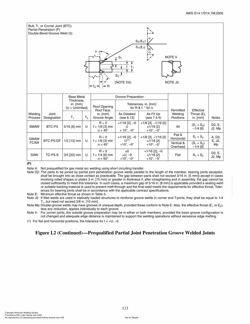
ßÉÍ ÜïìòïñÜïìòïÓæîððë
113
øÚ÷
Ò±¬» ßæ Ò±¬ °®»¯«¿´·º·»¼ º±® ¹¿ ³»¬¿´ ¿®½ ©»´¼·²¹ «·²¹ ¸±®¬ ½·®½«·¬·²¹ ¬®¿²º»®òÒ±¬» Üîæ ̸» °¿®¬ ¬± ¾» ¶±·²»¼ ¾§ °¿®¬·¿´ ¶±·²¬ °»²»¬®¿¬·±² ¹®±±ª» ©»´¼ °¿®¿´´»´ ¬± ¬¸» ´»²¹¬¸ ±º ¬¸» ³»³¾»®ô ¾»¿®·²¹ ¶±·²¬ »¨½»°¬»¼ô
¸¿´´ ¾» ¾®±«¹¸¬ ·²¬± ¿ ½´±» ½±²¬¿½¬ ¿ °®¿½¬·½¿¾´»ò ̸» ¹¿° ¾»¬©»»² °¿®¬ ¸¿´´ ²±¬ »¨½»»¼ íñïê ·²ò Åë ³³Ã÷ »¨½»°¬ ·² ½¿»·²ª±´ª·²¹ ®±´´»¼ ¸¿°» ±® °´¿¬» í ·²ò Åéë ³³Ã ±® ¹®»¿¬»® ·² ¬¸·½µ²» ·ºô ¿º¬»® ¬®¿·¹¸¬»²·²¹ ¿²¼ ·² ¿»³¾´§ô ¬¸» ¹¿° ½¿²²±¬ ¾»½´±»¼ «ºº·½·»²¬´§ ¬± ³»»¬ ¬¸· ¬±´»®¿²½»ò ײ «½¸ ½¿»ô ¿ ³¿¨·³«³ ¹¿° ±º ëñïê ·²ò Åè ³³Ã · ¿°°´·½¿¾´» °®±ª·¼»¼ ¿ »¿´·²¹ ©»´¼±® «·¬¿¾´» ¾¿½µ·²¹ ³¿¬»®·¿´ · «»¼ ¬± °®»ª»²¬ ³»´¬ó¬¸®±«¹¸ ¿²¼ ¬¸» º·²¿´ ©»´¼ ³»»¬ ¬¸» ®»¯«·®»³»²¬ º±® »ºº»½¬·ª» ¬¸®±¿¬ò ̱´»®ó¿²½» º±® ¾»¿®·²¹ ¶±·²¬ ¸¿´´ ¾» ·² ¿½½±®¼¿²½» ©·¬¸ ¬¸» ¿°°´·½¿¾´» ½±²¬®¿½¬ °»½·º·½¿¬·±²ò
Ò±¬» Ûæ Ó·²·³«³ »ºº»½¬·ª» ¬¸®±¿¬ ¿ ¸±©² ·² Ì¿¾´» ëòÒ±¬» Öîæ ׺ º·´´»¬ ©»´¼ ¿®» «»¼ ·² ¬¿¬·½¿´´§ ´±¿¼»¼ ¬®«½¬«®» ¬± ®»·²º±®½» ¹®±±ª» ©»´¼ ·² ½±®²»® ¿²¼ Ì󶱷²¬ô ¬¸»§ ¸¿´´ ¾» »¯«¿´ ¬± ïñì
Ìïô ¾«¬ ²»»¼ ²±¬ »¨½»»¼ íñè ·²ò Åïð ³³ÃòÒ±¬» Ó°æ ܱ«¾´»ó¹®±±ª» ©»´¼ ³¿§ ¸¿ª» ¹®±±ª» ±º «²»¯«¿´ ¼»°¬¸ô °®±ª·¼»¼ ¬¸»» ½±²º±®³ ¬± Ò±¬» Ûò ß´±ô ¬¸» »ºº»½¬·ª» ¬¸®±¿¬ øÛï ±® Ûî÷ô
´» ¿²§ ®»¼«½¬·±²ô ¿°°´·» ·²¼·ª·¼«¿´´§ ¬± »¿½¸ ¹®±±ª»òÒ±¬» Êæ Ú±® ½±®²»® ¶±·²¬ô ¬¸» ±«¬·¼» ¹®±±ª» °®»°¿®¿¬·±² ³¿§ ¾» ·² »·¬¸»® ±® ¾±¬¸ ³»³¾»®ô °®±ª·¼»¼ ¬¸» ¾¿·½ ¹®±±ª» ½±²º·¹«®¿¬·±² ·
²±¬ ½¸¿²¹»¼ ¿²¼ ¿¼»¯«¿¬» »¼¹» ¼·¬¿²½» · ³¿·²¬¿·²»¼ ¬± «°°±®¬ ¬¸» ©»´¼·²¹ ±°»®¿¬·±² ©·¬¸±«¬ »¨½»·ª» »¼¹» ³»´¬·²¹ò
øï÷ Ú±® º´¿¬ ¿²¼ ¸±®·¦±²¬¿´ °±·¬·±²ô ¬¸» ¬±´»®¿²½» º±® º ã õËô �ðò
Figure I.2 (Continued)�Prequalified Partial Joint Penetration Groove Welded Joints
Þ«¬¬ô Ìóô ±® ݱ®²»® Ö±·²¬ øÞÌÝ÷ﮬ·¿´ л²»¬®¿¬·±² øÐ÷ܱ«¾´»óÞ»ª»´óÙ®±±ª» É»´¼ øë÷
É»´¼·²¹ Ю±½»
Ö±·²¬ Ü»·¹²¿¬·±²
Þ¿» Ó»¬¿´ ̸·½µ²»ô
·²ò ų³ÃøË ã ˲´·³·¬»¼÷
Ù®±±ª» Ю»°¿®¿¬·±²
л®³·¬¬»¼ É»´¼·²¹ б·¬·±²
Ûºº»½¬·ª» ̸®±¿¬ øÛ÷ô
·²ò ų³Ã Ò±¬»
ᱬ Ñ°»²·²¹Î±±¬ Ú¿½»ô
·²ò ų³ÃÙ®±±ª» ß²¹´»
̱´»®¿²½»ô ·²ò ų³Ãº±® Î ú ºå p º±®
Ìï Ìî
ß Ü»¬¿·´»¼ø»» êòïí÷
ß Ú·¬ Ë°ø»» éòìòì÷
ÍÓßÉ ÞÌÝóÐë ëñïê Åèà ³·² ËÎ ã ð
º ã ïñè Åíà ³·²ã ìëp
õïñïê ÅîÃô �ðË
õ ïðpô �ðp
õïñè ÅíÃô �ïñïê ÅîÃoïñïê ÅîÃõïðpô �ëp
ß´´øÍï õ Íî÷�ïñì ÅêÃ
Üîô Ûô Öîô Ó°
ÙÓßÉÚÝßÉ
ÞÌÝóÐëóÙÚ ïñî Åïíà ³·² ËÎ ã ð
º ã ïñè Åíà ³·²ã ìëp
õïñïê ÅîÃô �ðËøï÷
õïðpô �ðp
õïñè ÅíÃô �ïñïê ÅîÃoïñïê ÅîÃõïðpô �ëp
Ú´¿¬ ú ر®·¦±²¬¿´
Íï õ Íî ßô Üîô Ûô Öîô
Ó°Ê»®¬·½¿´ ú Ѫ»®¸»¿¼
øÍï õ Íî÷�ïñì ÅêÃ
ÍßÉ ÌÝóÐëóÍ íñì Åîðà ³·² ËÎ ã ð
º ã ïñì Åêà ³·²ã êðp
oðõËô �ð
õïðpô �ðp
õïñïê ÅîÃô �ðoïñïê ÅîÃõïðpô �ëp
Ú´¿¬ Íï õ ÍîÜîô Ûô Öîô Ó°
ݱ°§®·¹¸¬ ß³»®·½¿² É»´¼·²¹ ͱ½·»¬§ Ю±ª·¼»¼ ¾§ ×ØÍ «²¼»® ´·½»²» ©·¬¸ ßÉÍ
Ò±¬ º±® λ¿´»Ò± ®»°®±¼«½¬·±² ±® ²»¬©±®µ·²¹ °»®³·¬¬»¼ ©·¬¸±«¬ ´·½»²» º®±³ ×ØÍ
óóÀôôÀôôÀóÀóÀôôÀôôÀôÀôôÀóóó
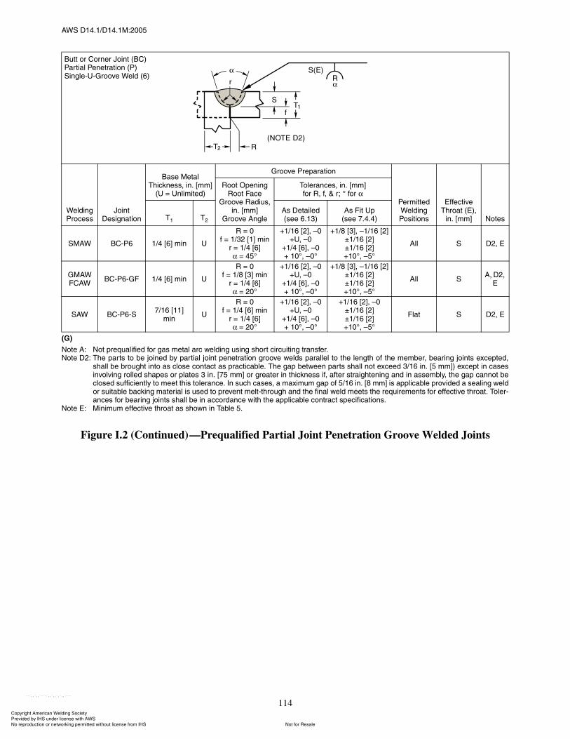
ßÉÍ ÜïìòïñÜïìòïÓæîððë
114
øÙ÷
Ò±¬» ßæ Ò±¬ °®»¯«¿´·º·»¼ º±® ¹¿ ³»¬¿´ ¿®½ ©»´¼·²¹ «·²¹ ¸±®¬ ½·®½«·¬·²¹ ¬®¿²º»®òÒ±¬» Üîæ ̸» °¿®¬ ¬± ¾» ¶±·²»¼ ¾§ °¿®¬·¿´ ¶±·²¬ °»²»¬®¿¬·±² ¹®±±ª» ©»´¼ °¿®¿´´»´ ¬± ¬¸» ´»²¹¬¸ ±º ¬¸» ³»³¾»®ô ¾»¿®·²¹ ¶±·²¬ »¨½»°¬»¼ô
¸¿´´ ¾» ¾®±«¹¸¬ ·²¬± ¿ ½´±» ½±²¬¿½¬ ¿ °®¿½¬·½¿¾´»ò ̸» ¹¿° ¾»¬©»»² °¿®¬ ¸¿´´ ²±¬ »¨½»»¼ íñïê ·²ò Åë ³³Ã÷ »¨½»°¬ ·² ½¿»·²ª±´ª·²¹ ®±´´»¼ ¸¿°» ±® °´¿¬» í ·²ò Åéë ³³Ã ±® ¹®»¿¬»® ·² ¬¸·½µ²» ·ºô ¿º¬»® ¬®¿·¹¸¬»²·²¹ ¿²¼ ·² ¿»³¾´§ô ¬¸» ¹¿° ½¿²²±¬ ¾»½´±»¼ «ºº·½·»²¬´§ ¬± ³»»¬ ¬¸· ¬±´»®¿²½»ò ײ «½¸ ½¿»ô ¿ ³¿¨·³«³ ¹¿° ±º ëñïê ·²ò Åè ³³Ã · ¿°°´·½¿¾´» °®±ª·¼»¼ ¿ »¿´·²¹ ©»´¼±® «·¬¿¾´» ¾¿½µ·²¹ ³¿¬»®·¿´ · «»¼ ¬± °®»ª»²¬ ³»´¬ó¬¸®±«¹¸ ¿²¼ ¬¸» º·²¿´ ©»´¼ ³»»¬ ¬¸» ®»¯«·®»³»²¬ º±® »ºº»½¬·ª» ¬¸®±¿¬ò ̱´»®ó¿²½» º±® ¾»¿®·²¹ ¶±·²¬ ¸¿´´ ¾» ·² ¿½½±®¼¿²½» ©·¬¸ ¬¸» ¿°°´·½¿¾´» ½±²¬®¿½¬ °»½·º·½¿¬·±²ò
Ò±¬» Ûæ Ó·²·³«³ »ºº»½¬·ª» ¬¸®±¿¬ ¿ ¸±©² ·² Ì¿¾´» ëò
Figure I.2 (Continued)�Prequalified Partial Joint Penetration Groove Welded Joints
Þ«¬¬ ±® ݱ®²»® Ö±·²¬ øÞÝ÷ﮬ·¿´ л²»¬®¿¬·±² øÐ÷Í·²¹´»óËóÙ®±±ª» É»´¼ øê÷
É»´¼·²¹ Ю±½»
Ö±·²¬ Ü»·¹²¿¬·±²
Þ¿» Ó»¬¿´ ̸·½µ²»ô ·²ò ų³Ã
øË ã ˲´·³·¬»¼÷
Ù®±±ª» Ю»°¿®¿¬·±²
л®³·¬¬»¼ É»´¼·²¹ б·¬·±²
Ûºº»½¬·ª» ̸®±¿¬ øÛ÷ô
·²ò ų³Ã Ò±¬»
ᱬ Ñ°»²·²¹Î±±¬ Ú¿½»
Ù®±±ª» ο¼·«ô·²ò ų³Ã
Ù®±±ª» ß²¹´»
̱´»®¿²½»ô ·²ò ų³Ãº±® Îô ºô ú ®å p º±®
Ìï Ìî
ß Ü»¬¿·´»¼ø»» êòïí÷
ß Ú·¬ Ë°ø»» éòìòì÷
ÍÓßÉ ÞÝóÐê ïñì Åêà ³·² Ë
Î ã ðº ã ïñíî Åïà ³·²
® ã ïñì ÅêÃã ìëp
õïñïê ÅîÃô �ðõËô �ð
õïñì ÅêÃô �ðõ ïðpô �ðp
õïñè ÅíÃô �ïñïê ÅîÃoïñïê ÅîÃoïñïê ÅîÃõïðpô �ëp
ß´´ Í Üîô Û
ÙÓßÉÚÝßÉ
ÞÝóÐêóÙÚ ïñì Åêà ³·² Ë
Î ã ðº ã ïñè Åíà ³·²
® ã ïñì ÅêÃã îðp
õïñïê ÅîÃô �ðõËô �ð
õïñì ÅêÃô �ðõ ïðpô �ðp
õïñè ÅíÃô �ïñïê ÅîÃoïñïê ÅîÃoïñïê ÅîÃõïðpô �ëp
ß´´ Íßô Üîô
Û
ÍßÉ ÞÝóÐêóÍéñïê ÅïïÃ
³·²Ë
Î ã ðº ã ïñì Åêà ³·²
® ã ïñì ÅêÃã îðp
õïñïê ÅîÃô �ðõËô �ð
õïñì ÅêÃô �ðõ ïðpô �ðp
õïñïê ÅîÃô �ðoïñïê ÅîÃoïñïê ÅîÃõïðpô �ëp
Ú´¿¬ Í Üîô Û
ݱ°§®·¹¸¬ ß³»®·½¿² É»´¼·²¹ ͱ½·»¬§ Ю±ª·¼»¼ ¾§ ×ØÍ «²¼»® ´·½»²» ©·¬¸ ßÉÍ
Ò±¬ º±® λ¿´»Ò± ®»°®±¼«½¬·±² ±® ²»¬©±®µ·²¹ °»®³·¬¬»¼ ©·¬¸±«¬ ´·½»²» º®±³ ×ØÍ
óóÀôôÀôôÀóÀóÀôôÀôôÀôÀôôÀóóó
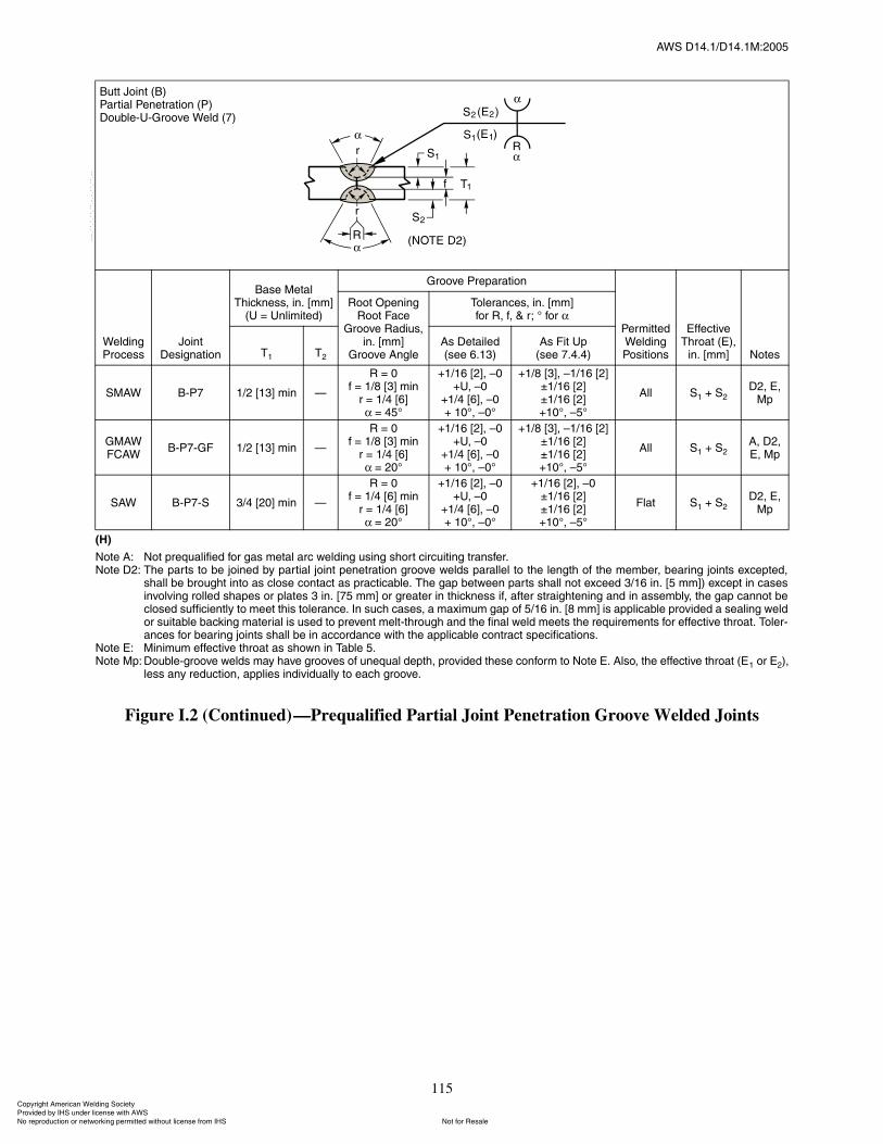
ßÉÍ ÜïìòïñÜïìòïÓæîððë
115
øØ÷
Ò±¬» ßæ Ò±¬ °®»¯«¿´·º·»¼ º±® ¹¿ ³»¬¿´ ¿®½ ©»´¼·²¹ «·²¹ ¸±®¬ ½·®½«·¬·²¹ ¬®¿²º»®òÒ±¬» Üîæ ̸» °¿®¬ ¬± ¾» ¶±·²»¼ ¾§ °¿®¬·¿´ ¶±·²¬ °»²»¬®¿¬·±² ¹®±±ª» ©»´¼ °¿®¿´´»´ ¬± ¬¸» ´»²¹¬¸ ±º ¬¸» ³»³¾»®ô ¾»¿®·²¹ ¶±·²¬ »¨½»°¬»¼ô
¸¿´´ ¾» ¾®±«¹¸¬ ·²¬± ¿ ½´±» ½±²¬¿½¬ ¿ °®¿½¬·½¿¾´»ò ̸» ¹¿° ¾»¬©»»² °¿®¬ ¸¿´´ ²±¬ »¨½»»¼ íñïê ·²ò Åë ³³Ã÷ »¨½»°¬ ·² ½¿»·²ª±´ª·²¹ ®±´´»¼ ¸¿°» ±® °´¿¬» í ·²ò Åéë ³³Ã ±® ¹®»¿¬»® ·² ¬¸·½µ²» ·ºô ¿º¬»® ¬®¿·¹¸¬»²·²¹ ¿²¼ ·² ¿»³¾´§ô ¬¸» ¹¿° ½¿²²±¬ ¾»½´±»¼ «ºº·½·»²¬´§ ¬± ³»»¬ ¬¸· ¬±´»®¿²½»ò ײ «½¸ ½¿»ô ¿ ³¿¨·³«³ ¹¿° ±º ëñïê ·²ò Åè ³³Ã · ¿°°´·½¿¾´» °®±ª·¼»¼ ¿ »¿´·²¹ ©»´¼±® «·¬¿¾´» ¾¿½µ·²¹ ³¿¬»®·¿´ · «»¼ ¬± °®»ª»²¬ ³»´¬ó¬¸®±«¹¸ ¿²¼ ¬¸» º·²¿´ ©»´¼ ³»»¬ ¬¸» ®»¯«·®»³»²¬ º±® »ºº»½¬·ª» ¬¸®±¿¬ò ̱´»®ó¿²½» º±® ¾»¿®·²¹ ¶±·²¬ ¸¿´´ ¾» ·² ¿½½±®¼¿²½» ©·¬¸ ¬¸» ¿°°´·½¿¾´» ½±²¬®¿½¬ °»½·º·½¿¬·±²ò
Ò±¬» Ûæ Ó·²·³«³ »ºº»½¬·ª» ¬¸®±¿¬ ¿ ¸±©² ·² Ì¿¾´» ëòÒ±¬» Ó°æ ܱ«¾´»ó¹®±±ª» ©»´¼ ³¿§ ¸¿ª» ¹®±±ª» ±º «²»¯«¿´ ¼»°¬¸ô °®±ª·¼»¼ ¬¸»» ½±²º±®³ ¬± Ò±¬» Ûò ß´±ô ¬¸» »ºº»½¬·ª» ¬¸®±¿¬ øÛï ±® Ûî÷ô
´» ¿²§ ®»¼«½¬·±²ô ¿°°´·» ·²¼·ª·¼«¿´´§ ¬± »¿½¸ ¹®±±ª»ò
Figure I.2 (Continued)�Prequalified Partial Joint Penetration Groove Welded Joints
Þ«¬¬ Ö±·²¬ øÞ÷ﮬ·¿´ л²»¬®¿¬·±² øÐ÷ܱ«¾´»óËóÙ®±±ª» É»´¼ øé÷
É»´¼·²¹ Ю±½»
Ö±·²¬ Ü»·¹²¿¬·±²
Þ¿» Ó»¬¿´ ̸·½µ²»ô ·²ò ų³Ã
øË ã ˲´·³·¬»¼÷
Ù®±±ª» Ю»°¿®¿¬·±²
л®³·¬¬»¼ É»´¼·²¹ б·¬·±²
Ûºº»½¬·ª» ̸®±¿¬ øÛ÷ô
·²ò ų³Ã Ò±¬»
ᱬ Ñ°»²·²¹Î±±¬ Ú¿½»
Ù®±±ª» ο¼·«ô·²ò ų³Ã
Ù®±±ª» ß²¹´»
̱´»®¿²½»ô ·²ò ų³Ãº±® Îô ºô ú ®å p º±®
Ìï Ìî
ß Ü»¬¿·´»¼ø»» êòïí÷
ß Ú·¬ Ë°ø»» éòìòì÷
ÍÓßÉ ÞóÐé ïñî Åïíà ³·² �
Î ã ðº ã ïñè Åíà ³·²
® ã ïñì ÅêÃã ìëp
õïñïê ÅîÃô �ðõËô �ð
õïñì ÅêÃô �ðõ ïðpô �ðp
õïñè ÅíÃô �ïñïê ÅîÃoïñïê ÅîÃoïñïê ÅîÃõïðpô �ëp
ß´´ Íï õ ÍîÜîô Ûô
Ó°
ÙÓßÉÚÝßÉ
ÞóÐéóÙÚ ïñî Åïíà ³·² �
Î ã ðº ã ïñè Åíà ³·²
® ã ïñì ÅêÃã îðp
õïñïê ÅîÃô �ðõËô �ð
õïñì ÅêÃô �ðõ ïðpô �ðp
õïñè ÅíÃô �ïñïê ÅîÃoïñïê ÅîÃoïñïê ÅîÃõïðpô �ëp
ß´´ Íï õ Íîßô Üîô Ûô Ó°
ÍßÉ ÞóÐéóÍ íñì Åîðà ³·² �
Î ã ðº ã ïñì Åêà ³·²
® ã ïñì ÅêÃã îðp
õïñïê ÅîÃô �ðõËô �ð
õïñì ÅêÃô �ðõ ïðpô �ðp
õïñïê ÅîÃô �ðoïñïê ÅîÃoïñïê ÅîÃõïðpô �ëp
Ú´¿¬ Íï õ ÍîÜîô Ûô
Ó°
ݱ°§®·¹¸¬ ß³»®·½¿² É»´¼·²¹ ͱ½·»¬§ Ю±ª·¼»¼ ¾§ ×ØÍ «²¼»® ´·½»²» ©·¬¸ ßÉÍ
Ò±¬ º±® λ¿´»Ò± ®»°®±¼«½¬·±² ±® ²»¬©±®µ·²¹ °»®³·¬¬»¼ ©·¬¸±«¬ ´·½»²» º®±³ ×ØÍ
óóÀôôÀôôÀóÀóÀôôÀôôÀôÀôôÀóóó

ßÉÍ ÜïìòïñÜïìòïÓæîððë
116
ø×÷
Ò±¬» ßæ Ò±¬ °®»¯«¿´·º·»¼ º±® ¹¿ ³»¬¿´ ¿®½ ©»´¼·²¹ «·²¹ ¸±®¬ ½·®½«·¬·²¹ ¬®¿²º»®òÒ±¬» Üîæ ̸» °¿®¬ ¬± ¾» ¶±·²»¼ ¾§ °¿®¬·¿´ ¶±·²¬ °»²»¬®¿¬·±² ¹®±±ª» ©»´¼ °¿®¿´´»´ ¬± ¬¸» ´»²¹¬¸ ±º ¬¸» ³»³¾»®ô ¾»¿®·²¹ ¶±·²¬ »¨½»°¬»¼ô
¸¿´´ ¾» ¾®±«¹¸¬ ·²¬± ¿ ½´±» ½±²¬¿½¬ ¿ °®¿½¬·½¿¾´»ò ̸» ¹¿° ¾»¬©»»² °¿®¬ ¸¿´´ ²±¬ »¨½»»¼ íñïê ·²ò Åë ³³Ã÷ »¨½»°¬ ·² ½¿»·²ª±´ª·²¹ ®±´´»¼ ¸¿°» ±® °´¿¬» í ·²ò Åéë ³³Ã ±® ¹®»¿¬»® ·² ¬¸·½µ²» ·ºô ¿º¬»® ¬®¿·¹¸¬»²·²¹ ¿²¼ ·² ¿»³¾´§ô ¬¸» ¹¿° ½¿²²±¬ ¾»½´±»¼ «ºº·½·»²¬´§ ¬± ³»»¬ ¬¸· ¬±´»®¿²½»ò ײ «½¸ ½¿»ô ¿ ³¿¨·³«³ ¹¿° ±º ëñïê ·²ò Åè ³³Ã · ¿°°´·½¿¾´» °®±ª·¼»¼ ¿ »¿´·²¹ ©»´¼±® «·¬¿¾´» ¾¿½µ·²¹ ³¿¬»®·¿´ · «»¼ ¬± °®»ª»²¬ ³»´¬ó¬¸®±«¹¸ ¿²¼ ¬¸» º·²¿´ ©»´¼ ³»»¬ ¬¸» ®»¯«·®»³»²¬ º±® »ºº»½¬·ª» ¬¸®±¿¬ò ̱´»®ó¿²½» º±® ¾»¿®·²¹ ¶±·²¬ ¸¿´´ ¾» ·² ¿½½±®¼¿²½» ©·¬¸ ¬¸» ¿°°´·½¿¾´» ½±²¬®¿½¬ °»½·º·½¿¬·±²ò
Ò±¬» Ûæ Ó·²·³«³ »ºº»½¬·ª» ¬¸®±¿¬ ¿ ¸±©² ·² Ì¿¾´» ëòÒ±¬» Öîæ ׺ º·´´»¬ ©»´¼ ¿®» «»¼ ·² ¬¿¬·½¿´´§ ´±¿¼»¼ ¬®«½¬«®» ¬± ®»·²º±®½» ¹®±±ª» ©»´¼ ·² ½±®²»® ¿²¼ Ì󶱷²¬ô ¬¸»§ ¸¿´´ ¾» »¯«¿´ ¬± ïñì
Ìïô ¾«¬ ²»»¼ ²±¬ »¨½»»¼ íñè ·²ò Åïð ³³ÃòÒ±¬» Êæ Ú±® ½±®²»® ¶±·²¬ô ¬¸» ±«¬·¼» ¹®±±ª» °®»°¿®¿¬·±² ³¿§ ¾» ·² »·¬¸»® ±® ¾±¬¸ ³»³¾»®ô °®±ª·¼»¼ ¬¸» ¾¿·½ ¹®±±ª» ½±²º·¹«®¿¬·±² ·
²±¬ ½¸¿²¹»¼ ¿²¼ ¿¼»¯«¿¬» »¼¹» ¼·¬¿²½» · ³¿·²¬¿·²»¼ ¬± «°°±®¬ ¬¸» ©»´¼·²¹ ±°»®¿¬·±² ©·¬¸±«¬ »¨½»·ª» »¼¹» ³»´¬·²¹ò
Figure I.2 (Continued)�Prequalified Partial Joint Penetration Groove Welded Joints
Þ«¬¬ Ö±·²¬ øÞ÷ÌóÖ±·²¬ øÌ÷ݱ®²»® Ö±·²¬ øÝ÷ﮬ·¿´ л²»¬®¿¬·±² øÐ÷Í·²¹´»óÖóÙ®±±ª» É»´¼ øè÷
É»´¼·²¹ Ю±½»
Ö±·²¬ Ü»·¹²¿¬·±²
Þ¿» Ó»¬¿´ ̸·½µ²»ô ·²ò ų³Ã
øË ã ˲´·³·¬»¼÷
Ù®±±ª» Ю»°¿®¿¬·±²
л®³·¬¬»¼ É»´¼·²¹ б·¬·±²
Ûºº»½¬·ª» ̸®±¿¬
øÛ÷ô·²ò ų³Ã Ò±¬»
ᱬ Ñ°»²·²¹Î±±¬ Ú¿½»
Ù®±±ª» ο¼·«ô·²ò ų³Ã
Ù®±±ª» ß²¹´»
̱´»®¿²½»ô ·²ò ų³Ãº±® Îô ºô ú ®å p º±®
Ìï Ìî
ß Ü»¬¿·´»¼ø»» êòïí÷
ß Ú·¬ Ë°ø»» éòìòì÷
ÍÓßÉ
ÌÝóÐèøÌ ú ײ·¼»
ݱ®²»® Ö±·²¬÷
ïñì Åêà ³·² Ë
Î ã ðº ã ïñè Åíà ³·²
® ã íñè ÅïðÃã ìëp
õïñïê ÅîÃô �ðõËô �ð
õïñì ÅêÃô �ðõïðpô �ðp
õïñè ÅíÃô �ïñïê ÅîÃoïñïê ÅîÃoïñïê ÅîÃõïðpô �ëp
ß´´ ÍÜîô Ûô
Öî
ÞÝóÐèøÞ«¬¬ ú Ñ«¬·¼»Ý±®²»® Ö±·²¬÷
ïñì Åêà ³·² Ë
Î ã ðº ã ïñè Åíà ³·²
® ã íñè ÅïðÃã íðp
õïñïê ÅîÃô �ðõËô �ð
õïñì ÅêÃô �ðõïðpô �ðp
õïñè ÅíÃô �ïñïê ÅîÃoïñïê ÅîÃoïñïê ÅîÃõïðpô �ëp
ß´´ Í Üîô Ûô Ê
ÙÓßÉÚÝßÉ
ÌÝóÐèóÙÚøÌ ú ײ·¼»
ݱ®²»® Ö±·²¬÷ïñì Åêà ³·² Ë
Î ã ðº ã ïñè Åíà ³·²
® ã íñè ÅïðÃã ìëp
õïñïê ÅîÃô �ðõËô �ð
õïñì ÅêÃô �ðõïðpô �ðp
õïñè ÅíÃô �ïñïê ÅîÃoïñïê ÅîÃoïñïê ÅîÃõïðpô �ëp
ß´´ Íßô Üîô Ûô Öî
ÞÝóÐèóÙÚ øÞ«¬¬ ú Ñ«¬·¼»Ý±®²»® Ö±·²¬÷
ïñì Åêà ³·² Ë
Î ã ðº ã ïñè Åíà ³·²
® ã íñè ÅïðÃã íðp
õïñïê ÅîÃô �ðõËô �ð
õïñì ÅêÃô �ðõïðpô �ðp
õïñè ÅíÃô �ïñïê ÅîÃoïñïê ÅîÃoïñïê ÅîÃõïðpô �ëp
ß´´ Íßô Üîô Ûô Ê
꧃
ÝóÐèóÍøÑ«¬·¼»Ý±®²»®÷
éñïê Åïïà ³·² Ë
Î ã ðº ã ïñì Åêà ³·²
® ã ïñî ÅïíÃã îðp
oðõËô �ð
õïñì ÅêÃô �ðõïðpô �ðp
õïñïê ÅîÃô �ðoïñïê ÅîÃoïñïê ÅîÃõïðpô �ëp
Ú´¿¬ Í Üîô Ûô Ê
ÌóÐèóÍøÌó ú ײ·¼»
ݱ®²»®÷éñïê Åïïà ³·² Ë
Î ã ðº ã ïñì Åêà ³·²
® ã ïñî ÅïíÃã ìëp
oðõËô �ð
õïñì ÅêÃô �ðõïðpô �ðp
õïñïê ÅîÃô �ðoïñïê ÅîÃoïñïê ÅîÃõïðpô �ëp
Ú´¿¬ ÍÜîô Ûô
Öî
ݱ°§®·¹¸¬ ß³»®·½¿² É»´¼·²¹ ͱ½·»¬§ Ю±ª·¼»¼ ¾§ ×ØÍ «²¼»® ´·½»²» ©·¬¸ ßÉÍ
Ò±¬ º±® λ¿´»Ò± ®»°®±¼«½¬·±² ±® ²»¬©±®µ·²¹ °»®³·¬¬»¼ ©·¬¸±«¬ ´·½»²» º®±³ ×ØÍ
óóÀôôÀôôÀóÀóÀôôÀôôÀôÀôôÀóóó
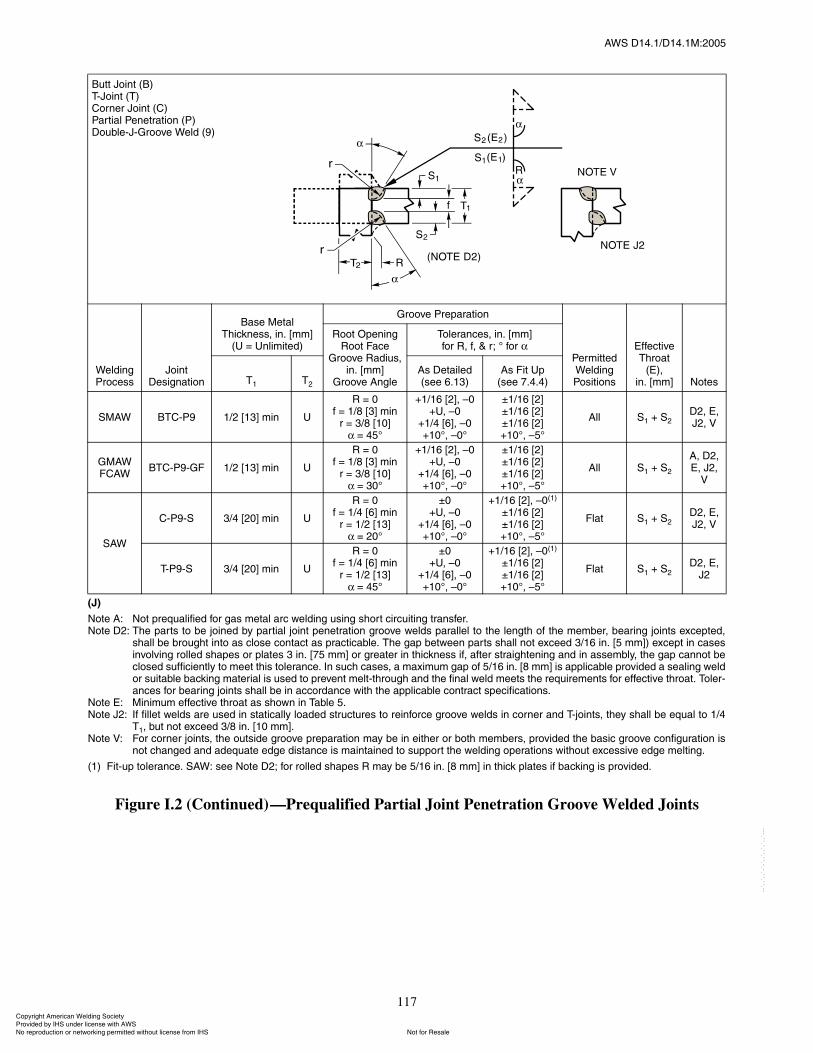
ßÉÍ ÜïìòïñÜïìòïÓæîððë
117
øÖ÷
Ò±¬» ßæ Ò±¬ °®»¯«¿´·º·»¼ º±® ¹¿ ³»¬¿´ ¿®½ ©»´¼·²¹ «·²¹ ¸±®¬ ½·®½«·¬·²¹ ¬®¿²º»®òÒ±¬» Üîæ ̸» °¿®¬ ¬± ¾» ¶±·²»¼ ¾§ °¿®¬·¿´ ¶±·²¬ °»²»¬®¿¬·±² ¹®±±ª» ©»´¼ °¿®¿´´»´ ¬± ¬¸» ´»²¹¬¸ ±º ¬¸» ³»³¾»®ô ¾»¿®·²¹ ¶±·²¬ »¨½»°¬»¼ô
¸¿´´ ¾» ¾®±«¹¸¬ ·²¬± ¿ ½´±» ½±²¬¿½¬ ¿ °®¿½¬·½¿¾´»ò ̸» ¹¿° ¾»¬©»»² °¿®¬ ¸¿´´ ²±¬ »¨½»»¼ íñïê ·²ò Åë ³³Ã÷ »¨½»°¬ ·² ½¿»·²ª±´ª·²¹ ®±´´»¼ ¸¿°» ±® °´¿¬» í ·²ò Åéë ³³Ã ±® ¹®»¿¬»® ·² ¬¸·½µ²» ·ºô ¿º¬»® ¬®¿·¹¸¬»²·²¹ ¿²¼ ·² ¿»³¾´§ô ¬¸» ¹¿° ½¿²²±¬ ¾»½´±»¼ «ºº·½·»²¬´§ ¬± ³»»¬ ¬¸· ¬±´»®¿²½»ò ײ «½¸ ½¿»ô ¿ ³¿¨·³«³ ¹¿° ±º ëñïê ·²ò Åè ³³Ã · ¿°°´·½¿¾´» °®±ª·¼»¼ ¿ »¿´·²¹ ©»´¼±® «·¬¿¾´» ¾¿½µ·²¹ ³¿¬»®·¿´ · «»¼ ¬± °®»ª»²¬ ³»´¬ó¬¸®±«¹¸ ¿²¼ ¬¸» º·²¿´ ©»´¼ ³»»¬ ¬¸» ®»¯«·®»³»²¬ º±® »ºº»½¬·ª» ¬¸®±¿¬ò ̱´»®ó¿²½» º±® ¾»¿®·²¹ ¶±·²¬ ¸¿´´ ¾» ·² ¿½½±®¼¿²½» ©·¬¸ ¬¸» ¿°°´·½¿¾´» ½±²¬®¿½¬ °»½·º·½¿¬·±²ò
Ò±¬» Ûæ Ó·²·³«³ »ºº»½¬·ª» ¬¸®±¿¬ ¿ ¸±©² ·² Ì¿¾´» ëòÒ±¬» Öîæ ׺ º·´´»¬ ©»´¼ ¿®» «»¼ ·² ¬¿¬·½¿´´§ ´±¿¼»¼ ¬®«½¬«®» ¬± ®»·²º±®½» ¹®±±ª» ©»´¼ ·² ½±®²»® ¿²¼ Ì󶱷²¬ô ¬¸»§ ¸¿´´ ¾» »¯«¿´ ¬± ïñì
Ìïô ¾«¬ ²±¬ »¨½»»¼ íñè ·²ò Åïð ³³ÃòÒ±¬» Êæ Ú±® ½±®²»® ¶±·²¬ô ¬¸» ±«¬·¼» ¹®±±ª» °®»°¿®¿¬·±² ³¿§ ¾» ·² »·¬¸»® ±® ¾±¬¸ ³»³¾»®ô °®±ª·¼»¼ ¬¸» ¾¿·½ ¹®±±ª» ½±²º·¹«®¿¬·±² ·
²±¬ ½¸¿²¹»¼ ¿²¼ ¿¼»¯«¿¬» »¼¹» ¼·¬¿²½» · ³¿·²¬¿·²»¼ ¬± «°°±®¬ ¬¸» ©»´¼·²¹ ±°»®¿¬·±² ©·¬¸±«¬ »¨½»·ª» »¼¹» ³»´¬·²¹ò
øï÷ Ú·¬ó«° ¬±´»®¿²½»ò ÍßÉæ »» Ò±¬» Üîå º±® ®±´´»¼ ¸¿°» Î ³¿§ ¾» ëñïê ·²ò Åè ³³Ã ·² ¬¸·½µ °´¿¬» ·º ¾¿½µ·²¹ · °®±ª·¼»¼ò
Figure I.2 (Continued)�Prequalified Partial Joint Penetration Groove Welded Joints
Þ«¬¬ Ö±·²¬ øÞ÷ÌóÖ±·²¬ øÌ÷ݱ®²»® Ö±·²¬ øÝ÷ﮬ·¿´ л²»¬®¿¬·±² øÐ÷ܱ«¾´»óÖóÙ®±±ª» É»´¼ øç÷
É»´¼·²¹ Ю±½»
Ö±·²¬ Ü»·¹²¿¬·±²
Þ¿» Ó»¬¿´ ̸·½µ²»ô ·²ò ų³Ã
øË ã ˲´·³·¬»¼÷
Ù®±±ª» Ю»°¿®¿¬·±²
л®³·¬¬»¼ É»´¼·²¹ б·¬·±²
Ûºº»½¬·ª» ̸®±¿¬
øÛ÷ô·²ò ų³Ã Ò±¬»
ᱬ Ñ°»²·²¹Î±±¬ Ú¿½»
Ù®±±ª» ο¼·«ô·²ò ų³Ã
Ù®±±ª» ß²¹´»
̱´»®¿²½»ô ·²ò ų³Ãº±® Îô ºô ú ®å p º±®
Ìï Ìî
ß Ü»¬¿·´»¼ø»» êòïí÷
ß Ú·¬ Ë°ø»» éòìòì÷
ÍÓßÉ ÞÌÝóÐç ïñî Åïíà ³·² Ë
Î ã ðº ã ïñè Åíà ³·²
® ã íñè ÅïðÃã ìëp
õïñïê ÅîÃô �ðõËô �ð
õïñì ÅêÃô �ðõïðpô �ðp
oïñïê ÅîÃoïñïê ÅîÃoïñïê ÅîÃõïðpô �ëp
ß´´ Íï õ ÍîÜîô Ûô Öîô Ê
ÙÓßÉÚÝßÉ
ÞÌÝóÐçóÙÚ ïñî Åïíà ³·² Ë
Î ã ðº ã ïñè Åíà ³·²
® ã íñè ÅïðÃã íðp
õïñïê ÅîÃô �ðõËô �ð
õïñì ÅêÃô �ðõïðpô �ðp
oïñïê ÅîÃoïñïê ÅîÃoïñïê ÅîÃõïðpô �ëp
ß´´ Íï õ Íî
ßô Üîô Ûô Öîô
Ê
꧃
ÝóÐçóÍ íñì Åîðà ³·² Ë
Î ã ðº ã ïñì Åêà ³·²
® ã ïñî ÅïíÃã îðp
oðõËô �ð
õïñì ÅêÃô �ðõïðpô �ðp
õïñïê ÅîÃô �ðøï÷
oïñïê ÅîÃoïñïê ÅîÃõïðpô �ëp
Ú´¿¬ Íï õ ÍîÜîô Ûô Öîô Ê
ÌóÐçóÍ íñì Åîðà ³·² Ë
Î ã ðº ã ïñì Åêà ³·²
® ã ïñî ÅïíÃã ìëp
oðõËô �ð
õïñì ÅêÃô �ðõïðpô �ðp
õïñïê ÅîÃô �ðøï÷
oïñïê ÅîÃoïñïê ÅîÃõïðpô �ëp
Ú´¿¬ Íï õ ÍîÜîô Ûô
Öî
ݱ°§®·¹¸¬ ß³»®·½¿² É»´¼·²¹ ͱ½·»¬§ Ю±ª·¼»¼ ¾§ ×ØÍ «²¼»® ´·½»²» ©·¬¸ ßÉÍ
Ò±¬ º±® λ¿´»Ò± ®»°®±¼«½¬·±² ±® ²»¬©±®µ·²¹ °»®³·¬¬»¼ ©·¬¸±«¬ ´·½»²» º®±³ ×ØÍ
óóÀôôÀôôÀóÀóÀôôÀôôÀôÀôôÀóóó

This page is intentionally blank.
118
ßÉÍ ÜïìòïñÜïìòïÓæîððë
ݱ°§®·¹¸¬ ß³»®·½¿² É»´¼·²¹ ͱ½·»¬§ Ю±ª·¼»¼ ¾§ ×ØÍ «²¼»® ´·½»²» ©·¬¸ ßÉÍ
Ò±¬ º±® λ¿´»Ò± ®»°®±¼«½¬·±² ±® ²»¬©±®µ·²¹ °»®³·¬¬»¼ ©·¬¸±«¬ ´·½»²» º®±³ ×ØÍ
óóÀôôÀôôÀóÀóÀôôÀôôÀôÀôôÀóóó
ßÉÍ ÜïìòïñÜïìòïÓæîððë
119
A1. Commentary on the Use of Welding Procedure Forms (Front) and (Back)
The form may be used to record information for eithera WPS or a PQR. The user should indicate their selectedapplication in the appropriate boxes or the user maychoose to blank out the inappropriate headings.
The WPSs and PQRs are to be signed by the autho-rized representative of the Manufacturer or Contractor.
For joint details on the WPS, a sketch or a reference tothe applicable prequalified joint detail may be used (e.g.,B-U4a).
A2. PrequalifiedThe WPS may be Prequalified in accordance with all
of the provisions of 9.1, in which case only the one-pagedocument, Form E1, is required.
A3. Qualified by TestingThe WPS may be qualified by testing in accordance
with the provisions of Part B of Section 9. In this case, asupporting PQR is required in addition to the WPS. Forthe PQR, Form E1 (Front) can again be used with anappropriate heading change. Also, the Form E1 (Back)may be used to record the test results and the certifyingstatement.
For the WPS, state the permitted ranges qualified bytesting or state the appropriate tolerances on essentialvariables (e.g., 250 A ±10%).
For the PQR, record the actual joint details and thevalues of essential variables used in the testing. Attach acopy of the Mill Test Report for the material tested. Test-ing laboratory data reports may also be included asbackup information.
The inclusion of items not required by this Specifica-tion is optional; however, they may be of use in settingup equipment or understanding test results.
ß²²»¨ ß
Í«¹¹»¬»¼ Ú±®³
(This Annex is not a part of AWS D14.1/D14.1M:2005, Specification for Welding of Industrial and Mill Cranesand Other Material Handling Equipment, but is included for informational purposes only.)
Nonmandatory Annexes
ݱ°§®·¹¸¬ ß³»®·½¿² É»´¼·²¹ ͱ½·»¬§ Ю±ª·¼»¼ ¾§ ×ØÍ «²¼»® ´·½»²» ©·¬¸ ßÉÍ
Ò±¬ º±® λ¿´»Ò± ®»°®±¼«½¬·±² ±® ²»¬©±®µ·²¹ °»®³·¬¬»¼ ©·¬¸±«¬ ´·½»²» º®±³ ×ØÍ
óóÀôôÀôôÀóÀóÀôôÀôôÀôÀôôÀóóó

ßÉÍ ÜïìòïñÜïìòïÓæîððë
120
ÉÛÔÜ×ÒÙ ÐÎÑÝÛÜËÎÛ ÍÐÛÝ×Ú×ÝßÌ×ÑÒ øÉÐÍ÷ Ç»
ÐÎÛÏËßÔ×Ú×ÛÜ ÁÁÁÁÁÁÁÁÁÁ ÏËßÔ×Ú×ÛÜ ÞÇ ÌÛÍÌ×ÒÙ ÁÁÁÁÁÁÁÁÁÁ
±® ÐÎÑÝÛÜËÎÛ ÏËßÔ×Ú×ÝßÌ×ÑÒ ÎÛÝÑÎÜÍ øÐÏÎ÷ Ç»
ÉÛÔÜ×ÒÙ ÐÎÑÝÛÜËÎÛ
Figure A.1�Sample Form E1, Front
×¼»²¬·º·½¿¬·±² ý ÁÁÁÁÁÁÁÁÁÁÁÁÁÁÁÁÁÁÁÁÁÁÁÁÁÁÁÁÁÁÁÁÁ
λª··±² ÁÁÁÁÁÁÁ Ü¿¬»ÁÁÁÁÁÁÁÁÁÁ Þ§ ÁÁÁÁÁÁÁÁÁÁÁÁ
ݱ³°¿²§ Ò¿³» ÁÁÁÁÁÁÁÁÁÁÁÁÁÁÁÁÁÁÁÁÁÁÁÁÁÁÁÁÁÁÁ ß«¬¸±®·¦»¼ ¾§ ÁÁÁÁÁÁÁÁÁÁÁÁÁÁÁÁÁÁ Ü¿¬» ÁÁÁÁÁÁÁÁÁÁ
É»´¼·²¹ Ю±½»ø»÷ ÁÁÁÁÁÁÁÁÁÁÁÁÁÁÁÁÁÁÁÁÁÁÁÁÁÁÁÁ ̧°»�Ó¿²«¿´ Í»³·óß«¬±³¿¬·½
Í«°°±®¬·²¹ ÐÏÎ Ò±òø÷ ÁÁÁÁÁÁÁÁÁÁÁÁÁÁÁÁÁÁÁÁÁÁÁÁÁÁ Ó¿½¸·²» ß«¬±³¿¬·½
ÖÑ×ÒÌ ÜÛÍ×ÙÒ ËÍÛÜ ÐÑÍ×Ì×ÑÒ
̧°»æ б·¬·±² ±º Ù®±±ª»æÁÁÁÁÁÁÁÁÁÁÁÁÁÁ Ú·´´»¬æ ÁÁÁÁÁÁÁÁÁÁ
Í·²¹´» ܱ«¾´» É»´¼ Ê»®¬·½¿´ Ю±¹®»·±²æ Ë° ܱ©²
Þ¿½µ·²¹æ Ç» Ò±
Þ¿½µ·²¹æ Þ¿½µ·²¹ Ó¿¬»®·¿´æ ÛÔÛÝÌÎ×ÝßÔ ÝØßÎßÝÌÛÎ×ÍÌ×ÝÍ
ᱬ Ñ°»²·²¹ ÁÁÁÁÁÁ ᱬ Ú¿½» Ü·³»²·±² ÁÁÁÁÁÁÁÁ ÁÁÁÁÁÁÁÁÁÁÁÁÁÁÁÁÁÁÁÁÁÁ
Ù®±±ª» ß²¹´»æ ÁÁÁÁÁÁÁÁÁÁÁ ο¼·« øÖ�Ë÷ ÁÁÁÁÁÁÁÁÁ Ì®¿²º»® Ó±¼» øÙÓßÉ÷ ͸±®¬óÝ·®½«·¬·²¹
Þ¿½µ Ù±«¹·²¹æ Ç» Ò± Ó»¬¸±¼ ÁÁÁÁÁÁÁ Ù´±¾«´¿® Í°®¿§
Ý«®®»²¬æ ßÝ ÜÝÛÐ ÜÝÛÒ Ð«´»¼
ÞßÍÛ ÓÛÌßÔÍ Ñ¬¸»® ÁÁÁÁÁÁÁÁÁÁÁÁÁÁÁÁÁÁÁÁÁÁÁÁÁÁÁÁÁÁÁÁÁÁÁÁÁÁÁÁ
Ó¿¬»®·¿´ Í°»½ò ÁÁÁÁÁÁÁÁÁÁÁÁÁÁÁÁÁÁÁÁÁÁÁÁÁÁÁÁÁÁÁÁÁ Ì«²¹¬»² Û´»½¬®±¼» øÙÌßÉ÷
̧°» ±® Ù®¿¼» ÁÁÁÁÁÁÁÁÁÁÁÁÁÁÁÁÁÁÁÁÁÁÁÁÁÁÁÁÁÁÁÁÁ Í·¦»æ ÁÁÁÁÁÁÁÁÁÁÁÁÁÁ
̸·½µ²»æ Ù®±±ª» ÁÁÁÁÁÁÁÁÁÁÁÁ Ú·´´»¬ ÁÁÁÁÁÁÁÁÁÁ ̧°»æ ÁÁÁÁÁÁÁÁÁÁÁÁÁÁ
Ü·¿³»¬»® øз°»÷ÁÁÁÁÁÁÁÁÁÁÁÁÁÁÁÁÁÁÁÁÁÁÁÁÁÁÁÁÁÁÁÁ
ÌÛÝØÒ×ÏËÛ
Ú×ÔÔÛÎ ÓÛÌßÔÍ Í¬®·²¹»® ±® É»¿ª» Þ»¿¼æ ÁÁÁÁÁÁÁÁÁÁÁÁÁÁÁÁÁÁÁÁÁÁÁÁÁ
ßÉÍ Í°»½·º·½¿¬·±²ÁÁÁÁÁÁÁÁÁÁÁÁÁÁÁÁÁÁÁÁÁÁÁÁÁÁÁÁÁÁ Ó«´¬·ó°¿ ±® Í·²¹´» п ø°»® ·¼»÷ÁÁÁÁÁÁÁÁÁÁÁÁÁÁÁÁÁ
ßÉÍ Ý´¿·º·½¿¬·±² ÁÁÁÁÁÁÁÁÁÁÁÁÁÁÁÁÁÁÁÁÁÁÁÁÁÁÁÁÁ Ò«³¾»® ±º Û´»½¬®±¼» ÁÁÁÁÁÁÁÁÁÁÁÁÁÁÁÁÁÁÁÁÁÁÁÁÁÁÁ
Û´»½¬®±¼» Í°¿½·²¹ Ô±²¹·¬«¼·²¿´ ÁÁÁÁÁÁÁÁÁÁÁÁ
Ô¿¬»®¿´ÁÁÁÁÁÁÁÁÁÁÁÁÁÁÁÁÁ
ÍØ×ÛÔÜ×ÒÙ ß²¹´» ÁÁÁÁÁÁÁÁÁÁÁÁÁÁÁÁÁ
Ú´«¨ ÁÁÁÁÁÁÁÁÁÁÁÁÁÁÁÁÁÁÁ Ù¿ ÁÁÁÁÁÁÁÁÁÁÁÁÁÁÁÁÁ
ݱ³°±·¬·±² ÁÁÁÁÁÁÁÁÁÁ ݱ²¬¿½¬ Ì«¾» ¬± ɱ®µ Ü·¬¿²½» ÁÁÁÁÁÁÁÁÁÁÁÁÁÁÁÁÁÁÁÁ
Û´»½¬®±¼»óÚ´«¨ øÝ´¿÷ÁÁÁÁÁ Ú´±© כּ ÁÁÁÁÁÁÁÁÁÁÁÁ л»²·²¹ ÁÁÁÁÁÁÁÁÁÁÁÁÁÁÁÁÁÁÁÁÁÁÁÁÁÁÁÁÁÁÁÁÁÁÁÁÁÁ
ÁÁÁÁÁÁÁÁÁÁÁÁÁÁÁÁÁÁÁÁÁÁ Ù¿ Ý«° Í·¦» ÁÁÁÁÁÁÁÁÁ ײ¬»®°¿ Ý´»¿²·²¹æ ÁÁÁÁÁÁÁÁÁÁÁÁÁÁÁÁÁÁÁÁÁÁÁÁÁÁÁÁÁ
ÐÎÛØÛßÌ ÐÑÍÌÉÛÔÜ ØÛßÌ ÌÎÛßÌÓÛÒÌ
Ю»¸»¿¬ Ì»³°òô Ó·² ÁÁÁÁÁÁÁÁÁÁÁÁÁÁÁÁÁÁÁÁÁÁÁÁÁÁÁÁÁ Ì»³°ò ÁÁÁÁÁÁÁÁÁÁÁÁÁÁÁÁÁÁÁÁÁÁÁÁÁÁÁÁÁÁÁÁÁÁÁÁÁÁÁÁ
ײ¬»®°¿ Ì»³°òô Ó·²ÁÁÁÁÁÁÁÁÁÁÁÁ Ó¿¨ÁÁÁÁÁÁÁÁÁÁ Ì·³» ÁÁÁÁÁÁÁÁÁÁÁÁÁÁÁÁÁÁÁÁÁÁÁÁÁÁÁÁÁÁÁÁÁÁÁÁÁÁÁÁÁ
п ±®
É»´¼
Ô¿§»®ø÷ Ю±½»
Ú·´´»® Ó»¬¿´ Ý«®®»²¬
ʱ´¬
Ì®¿ª»´
Í°»»¼ Ö±·²¬ Ü»¬¿·´Ý´¿ Ü·¿³ò
̧°» ú
б´¿®·¬§
ß³° ±® É·®»
Ú»»¼ Í°»»¼
ݱ°§®·¹¸¬ ß³»®·½¿² É»´¼·²¹ ͱ½·»¬§ Ю±ª·¼»¼ ¾§ ×ØÍ «²¼»® ´·½»²» ©·¬¸ ßÉÍ
Ò±¬ º±® λ¿´»Ò± ®»°®±¼«½¬·±² ±® ²»¬©±®µ·²¹ °»®³·¬¬»¼ ©·¬¸±«¬ ´·½»²» º®±³ ×ØÍ
óóÀôôÀôôÀóÀóÀôôÀôôÀôÀôôÀóóó

ßÉÍ ÜïìòïñÜïìòïÓæîððë
121
Ю±½»¼«®» Ï«¿´·º·½¿¬·±² λ½±®¼ øÐÏÎ÷ ý ÁÁÁÁÁÁÁÁÁÁ
Ì»¬ λ«´¬
Ê×ÍËßÔ ×ÒÍÐÛÝÌ×ÑÒ ÎßÜ×ÑÙÎßÐØ×ÝóËÔÌÎßÍÑÒ×Ý ÛÈßÓ×ÒßÌ×ÑÒ
ß°°»¿®¿²½»ÁÁÁÁÁÁÁÁÁÁÁÁÁÁÁÁÁÁÁÁÁÁÁÁÁÁÁÁÁÁÁÁÁÁÁ ÎÌ Î»°±®¬ Ò±òæ ÁÁÁÁÁÁÁÁÁ λ«´¬ ÁÁÁÁÁÁÁÁÁÁÁÁÁÁÁÁ
˲¼»®½«¬ ÁÁÁÁÁÁÁÁÁÁÁÁÁÁÁÁÁÁÁÁÁÁÁÁÁÁÁÁÁÁÁÁÁÁÁÁÁ ËÌ Î»°±®¬ Ò±òæ ÁÁÁÁÁÁÁÁÁÁ λ«´¬ ÁÁÁÁÁÁÁÁÁÁÁÁÁÁÁÁ
з°·²¹ °±®±·¬§ ÁÁÁÁÁÁÁÁÁÁÁÁÁÁÁÁÁÁÁÁÁÁÁÁÁÁÁÁÁÁÁÁ
ݱ²ª»¨·¬§ÁÁÁÁÁÁÁÁÁÁÁÁÁÁÁÁÁÁÁÁÁÁÁÁÁÁÁÁÁÁÁÁÁÁÁÁÁ Ú×ÔÔÛÌ ÉÛÔÜ ÌÛÍÌ ÎÛÍËÔÌÍ
Ì»¬ ¼¿¬» ÁÁÁÁÁÁÁÁÁÁÁÁÁÁÁÁÁÁÁÁÁÁÁÁÁÁÁÁÁÁÁÁÁÁÁÁÁ Ó·²·³«³ ·¦» ³«´¬·°´» °¿ Ó¿¨·³«³ ·¦» ·²¹´» °¿
É·¬²»»¼ ¾§ÁÁÁÁÁÁÁÁÁÁÁÁÁÁÁÁÁÁÁÁÁÁÁÁÁÁÁÁÁÁÁÁÁÁ Ó¿½®±»¬½¸ Ó¿½®±»¬½¸
ïò ÁÁÁÁÁÁÁ íò ÁÁÁÁÁÁÁÁ ïò ÁÁÁÁÁÁÁÁ íò ÁÁÁÁÁÁÁÁ
îò ÁÁÁÁÁÁÁ îò ÁÁÁÁÁÁÁÁ
ÑÌØÛÎ ÌÛÍÌÍ ßÔÔóÉÛÔÜóÓÛÌßÔ ÌÛÒÍ×ÑÒ ÌÛÍÌ
Ì»²·´» ¬®»²¹¬¸ô °· ÅÓпà ÁÁÁÁÁÁÁÁÁÁÁÁÁÁÁÁÁÁÁÁÁÁÁÁ
Ç·»´¼ °±·²¬ñ¬®»²¹¬¸ô °· ÅÓпà ÁÁÁÁÁÁÁÁÁÁÁÁÁÁÁÁÁÁÁÁÁ
Û´±²¹¿¬·±² ·² î ·²ò Åëð ³³Ãô û ÁÁÁÁÁÁÁÁÁÁÁÁÁÁÁÁÁÁÁÁÁ
Ô¿¾±®¿¬±®§ Ì»¬ Ò±ò ÁÁÁÁÁÁÁÁÁÁÁÁÁÁÁÁÁÁÁÁÁÁÁÁÁÁÁÁÁ
É»´¼»®� ²¿³» ÁÁÁÁÁÁÁÁÁÁÁÁÁÁÁÁÁÁÁÁÁÁÁÁÁÁÁÁÁÁÁÁ Ý´±½µ Ò±ò ÁÁÁÁÁÁÁÁÁÁÁÁÁÁ ͬ¿³° Ò±ò ÁÁÁÁÁÁÁÁÁÁÁÁ
ɸ± ¾§ ª·®¬«» ±º ¬¸»» ¬»¬ · ¿´± ¯«¿´·º·»¼ ¿ ¿² ·²¼·ª·¼«¿´ò
Ì»¬ ½±²¼«½¬»¼ ¾§ ÁÁÁÁÁÁÁÁÁÁÁÁÁÁÁÁÁÁÁÁÁÁÁÁÁÁÁÁÁÁÁÁÁÁÁÁÁÁÁÁÁÁÁÁÁÁÁÁÁÁÁÁÁÁÁÁÁ Ô¿¾±®¿¬±®§
Ô¿¾±®¿¬±®§ Ì»¬ Ò±ò ÁÁÁÁÁÁÁÁÁÁÁÁÁÁÁÁÁÁÁÁÁÁÁÁÁÁÁÁÁ
л® ÁÁÁÁÁÁÁÁÁÁÁÁÁÁÁÁÁÁÁÁÁÁÁÁÁÁÁÁÁÁÁÁÁÁÁÁÁÁÁÁÁÁ
É»ô ¬¸» «²¼»®·¹²»¼ô ½»®¬·º§ ¬¸¿¬ ¬¸» ¬¿¬»³»²¬ ·² ¬¸· ®»½±®¼ ¿®» ½±®®»½¬ ¿²¼ ¬¸¿¬ ¬¸» ¬»¬ ©»´¼ ©»®» °®»°¿®»¼ô ©»´¼»¼ô ¿²¼¬»¬»¼ ·² ¿½½±®¼¿²½» ©·¬¸ ¬¸» ®»¯«·®»³»²¬ ±º ßÉÍ Üïìòïô øÁÁÁÁÁÁÁÁÁÁ÷ò
ø§»¿®÷
Í·¹²»¼ ÁÁÁÁÁÁÁÁÁÁÁÁÁÁÁÁÁÁÁÁÁÁÁÁÁÁÁÁÁÁÁÁÁÁÁÁÁÁÁÓ¿²«º¿½¬«®»® ±® ݱ²¬®¿½¬±®
Þ§ ÁÁÁÁÁÁÁÁÁÁÁÁÁÁÁÁÁÁÁÁÁÁÁÁÁÁÁÁÁÁÁÁÁÁÁÁÁÁÁÁÁÁÁ
Ì·¬´» ÁÁÁÁÁÁÁÁÁÁÁÁÁÁÁÁÁÁÁÁÁÁÁÁÁÁÁÁÁÁÁÁÁÁÁÁÁÁÁÁÁ
Ü¿¬» ÁÁÁÁÁÁÁÁÁÁÁÁÁÁÁÁÁÁÁÁÁÁÁÁÁÁÁÁÁÁÁÁÁÁÁÁÁÁÁÁÁ
Figure A.2�Sample Form, E1, Back
ÌÛÒÍ×ÔÛ ÌÛÍÌ
Í°»½·³»²
Ò±òÉ·¼¬¸ ̸·½µ²» ß®»¿
Ë´¬·³¿¬» Ì»²·´»
Ô±¿¼ô ´¾
Ë´¬·³¿¬» ˲·¬
ͬ®»ô °·
ݸ¿®¿½¬»® ±º Ú¿·´«®»
¿²¼ Ô±½¿¬·±²
ÙË×ÜÛÜ ÞÛÒÜ ÌÛÍÌ
Í°»½·³»²
Ò±ò̧°» ±º Þ»²¼ λ«´¬ λ³¿®µ
ݱ°§®·¹¸¬ ß³»®·½¿² É»´¼·²¹ ͱ½·»¬§ Ю±ª·¼»¼ ¾§ ×ØÍ «²¼»® ´·½»²» ©·¬¸ ßÉÍ
Ò±¬ º±® λ¿´»Ò± ®»°®±¼«½¬·±² ±® ²»¬©±®µ·²¹ °»®³·¬¬»¼ ©·¬¸±«¬ ´·½»²» º®±³ ×ØÍ
óóÀôôÀôôÀóÀóÀôôÀôôÀôÀôôÀóóó
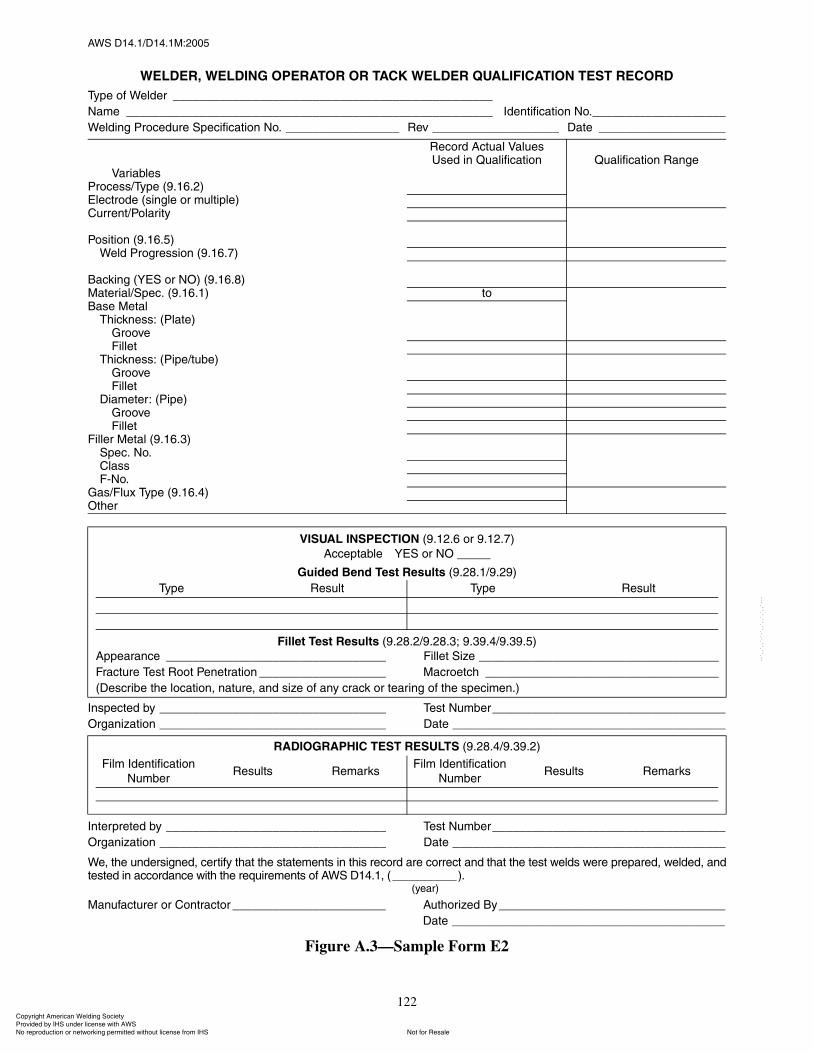
ßÉÍ ÜïìòïñÜïìòïÓæîððë
122
ÉÛÔÜÛÎô ÉÛÔÜ×ÒÙ ÑÐÛÎßÌÑÎ ÑÎ ÌßÝÕ ÉÛÔÜÛÎ ÏËßÔ×Ú×ÝßÌ×ÑÒ ÌÛÍÌ ÎÛÝÑÎÜ
̧°» ±º É»´¼»® ÁÁÁÁÁÁÁÁÁÁÁÁÁÁÁÁÁÁÁÁÁÁÁÁÁÁÁÁÁÁÁÁÁÁÁÁÁÁÁÁÁÁÁÁÁÁÁÁ
Ò¿³» ÁÁÁÁÁÁÁÁÁÁÁÁÁÁÁÁÁÁÁÁÁÁÁÁÁÁÁÁÁÁÁÁÁÁÁÁÁÁÁÁÁÁÁÁÁÁÁÁÁÁÁÁÁÁÁ ×¼»²¬·º·½¿¬·±² Ò±òÁÁÁÁÁÁÁÁÁÁÁÁÁÁÁÁÁÁÁÁ
É»´¼·²¹ Ю±½»¼«®» Í°»½·º·½¿¬·±² Ò±ò ÁÁÁÁÁÁÁÁÁÁÁÁÁÁÁÁÁ λª ÁÁÁÁÁÁÁÁÁÁÁÁÁÁÁÁÁÁÁ Ü¿¬» ÁÁÁÁÁÁÁÁÁÁÁÁÁÁÁÁÁÁÁ
ײ°»½¬»¼ ¾§ ÁÁÁÁÁÁÁÁÁÁÁÁÁÁÁÁÁÁÁÁÁÁÁÁÁÁÁÁÁÁÁÁÁÁ Ì»¬ Ò«³¾»®ÁÁÁÁÁÁÁÁÁÁÁÁÁÁÁÁÁÁÁÁÁÁÁÁÁÁÁÁÁÁÁÁÁÁÁ
Ñ®¹¿²·¦¿¬·±² ÁÁÁÁÁÁÁÁÁÁÁÁÁÁÁÁÁÁÁÁÁÁÁÁÁÁÁÁÁÁÁÁÁÁ Ü¿¬» ÁÁÁÁÁÁÁÁÁÁÁÁÁÁÁÁÁÁÁÁÁÁÁÁÁÁÁÁÁÁÁÁÁÁÁÁÁÁÁÁÁ
ײ¬»®°®»¬»¼ ¾§ ÁÁÁÁÁÁÁÁÁÁÁÁÁÁÁÁÁÁÁÁÁÁÁÁÁÁÁÁÁÁÁÁÁ Ì»¬ Ò«³¾»®ÁÁÁÁÁÁÁÁÁÁÁÁÁÁÁÁÁÁÁÁÁÁÁÁÁÁÁÁÁÁÁÁÁÁÁ
Ñ®¹¿²·¦¿¬·±² ÁÁÁÁÁÁÁÁÁÁÁÁÁÁÁÁÁÁÁÁÁÁÁÁÁÁÁÁÁÁÁÁÁÁ Ü¿¬» ÁÁÁÁÁÁÁÁÁÁÁÁÁÁÁÁÁÁÁÁÁÁÁÁÁÁÁÁÁÁÁÁÁÁÁÁÁÁÁÁÁ
É»ô ¬¸» «²¼»®·¹²»¼ô ½»®¬·º§ ¬¸¿¬ ¬¸» ¬¿¬»³»²¬ ·² ¬¸· ®»½±®¼ ¿®» ½±®®»½¬ ¿²¼ ¬¸¿¬ ¬¸» ¬»¬ ©»´¼ ©»®» °®»°¿®»¼ô ©»´¼»¼ô ¿²¼¬»¬»¼ ·² ¿½½±®¼¿²½» ©·¬¸ ¬¸» ®»¯«·®»³»²¬ ±º ßÉÍ Üïìòïô øÁÁÁÁÁÁÁÁÁÁ÷ò
ø§»¿®÷
Ó¿²«º¿½¬«®»® ±® ݱ²¬®¿½¬±® ÁÁÁÁÁÁÁÁÁÁÁÁÁÁÁÁÁÁÁÁÁÁÁ ß«¬¸±®·¦»¼ Þ§ÁÁÁÁÁÁÁÁÁÁÁÁÁÁÁÁÁÁÁÁÁÁÁÁÁÁÁÁÁÁÁÁÁÁ
Ü¿¬» ÁÁÁÁÁÁÁÁÁÁÁÁÁÁÁÁÁÁÁÁÁÁÁÁÁÁÁÁÁÁÁÁÁÁÁÁÁÁÁÁÁ
Figure A.3�Sample Form E2
λ½±®¼ ß½¬«¿´ Ê¿´«»Ë»¼ ·² Ï«¿´·º·½¿¬·±² Ï«¿´·º·½¿¬·±² ο²¹»
Ê¿®·¿¾´»Ð®±½»ņ̃°» øçòïêòî÷Û´»½¬®±¼» ø·²¹´» ±® ³«´¬·°´»÷Ý«®®»²¬ñб´¿®·¬§
б·¬·±² øçòïêòë÷É»´¼ Ю±¹®»·±² øçòïêòé÷
Þ¿½µ·²¹ øÇÛÍ ±® ÒÑ÷ øçòïêòè÷Ó¿¬»®·¿´ñÍ°»½ò øçòïêòï÷ ¬±Þ¿» Ó»¬¿´
̸·½µ²»æ øд¿¬»÷Ù®±±ª»Ú·´´»¬
̸·½µ²»æ øз°»ñ¬«¾»÷Ù®±±ª»Ú·´´»¬
Ü·¿³»¬»®æ øз°»÷Ù®±±ª»Ú·´´»¬
Ú·´´»® Ó»¬¿´ øçòïêòí÷Í°»½ò Ò±òÝ´¿ÚóÒ±ò
Ù¿ñÚ´«¨ ̧°» øçòïêòì÷Ѭ¸»®
Ê×ÍËßÔ ×ÒÍÐÛÝÌ×ÑÒ øçòïîòê ±® çòïîòé÷
ß½½»°¬¿¾´» ÇÛÍ ±® ÒÑ ÁÁÁÁÁ
Ù«·¼»¼ Þ»²¼ Ì»¬ λ«´¬ øçòîèòïñçòîç÷
̧°» λ«´¬ ̧°» λ«´¬
Ú·´´»¬ Ì»¬ λ«´¬ øçòîèòîñçòîèòíå çòíçòìñçòíçòë÷
ß°°»¿®¿²½» ÁÁÁÁÁÁÁÁÁÁÁÁÁÁÁÁÁÁÁÁÁÁÁÁÁÁÁÁÁÁÁÁÁ Ú·´´»¬ Í·¦» ÁÁÁÁÁÁÁÁÁÁÁÁÁÁÁÁÁÁÁÁÁÁÁÁÁÁÁÁÁÁÁÁÁÁÁÁ
Ú®¿½¬«®» Ì»¬ ᱬ л²»¬®¿¬·±² ÁÁÁÁÁÁÁÁÁÁÁÁÁÁÁÁÁÁÁ Ó¿½®±»¬½¸ ÁÁÁÁÁÁÁÁÁÁÁÁÁÁÁÁÁÁÁÁÁÁÁÁÁÁÁÁÁÁÁÁÁÁÁ
øÜ»½®·¾» ¬¸» ´±½¿¬·±²ô ²¿¬«®»ô ¿²¼ ·¦» ±º ¿²§ ½®¿½µ ±® ¬»¿®·²¹ ±º ¬¸» °»½·³»²ò÷
ÎßÜ×ÑÙÎßÐØ×Ý ÌÛÍÌ ÎÛÍËÔÌÍ øçòîèòìñçòíçòî÷
Ú·´³ ×¼»²¬·º·½¿¬·±²
Ò«³¾»®Î»«´¬ λ³¿®µ
Ú·´³ ×¼»²¬·º·½¿¬·±²
Ò«³¾»®Î»«´¬ λ³¿®µ
ݱ°§®·¹¸¬ ß³»®·½¿² É»´¼·²¹ ͱ½·»¬§ Ю±ª·¼»¼ ¾§ ×ØÍ «²¼»® ´·½»²» ©·¬¸ ßÉÍ
Ò±¬ º±® λ¿´»Ò± ®»°®±¼«½¬·±² ±® ²»¬©±®µ·²¹ °»®³·¬¬»¼ ©·¬¸±«¬ ´·½»²» º®±³ ×ØÍ
óóÀôôÀôôÀóÀóÀôôÀôôÀôÀôôÀóóó
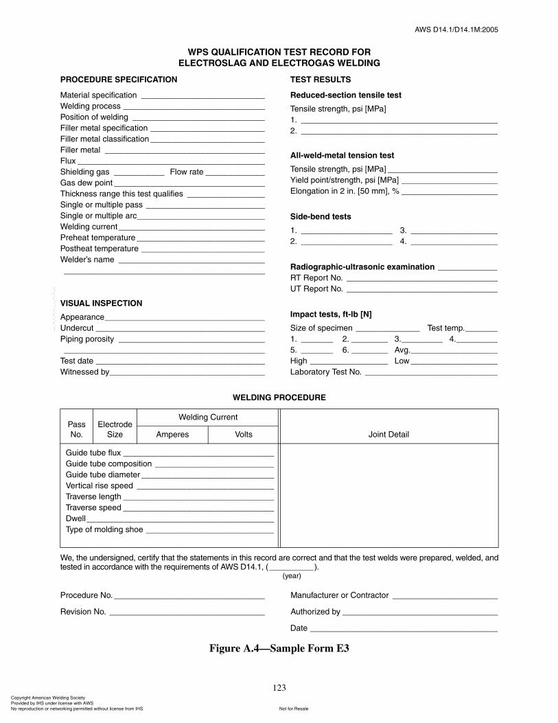
ßÉÍ ÜïìòïñÜïìòïÓæîððë
123
ÉÛÔÜ×ÒÙ ÐÎÑÝÛÜËÎÛ
É»ô ¬¸» «²¼»®·¹²»¼ô ½»®¬·º§ ¬¸¿¬ ¬¸» ¬¿¬»³»²¬ ·² ¬¸· ®»½±®¼ ¿®» ½±®®»½¬ ¿²¼ ¬¸¿¬ ¬¸» ¬»¬ ©»´¼ ©»®» °®»°¿®»¼ô ©»´¼»¼ô ¿²¼¬»¬»¼ ·² ¿½½±®¼¿²½» ©·¬¸ ¬¸» ®»¯«·®»³»²¬ ±º ßÉÍ Üïìòïô øÁÁÁÁÁÁÁÁÁÁ÷ò
ø§»¿®÷
Ю±½»¼«®» Ò±ò ÁÁÁÁÁÁÁÁÁÁÁÁÁÁÁÁÁÁÁÁÁÁÁÁÁÁÁÁÁÁÁÁÁ Ó¿²«º¿½¬«®»® ±® ݱ²¬®¿½¬±® ÁÁÁÁÁÁÁÁÁÁÁÁÁÁÁÁÁÁÁÁÁÁÁ
λª··±² Ò±ò ÁÁÁÁÁÁÁÁÁÁÁÁÁÁÁÁÁÁÁÁÁÁÁÁÁÁÁÁÁÁÁÁÁÁ ß«¬¸±®·¦»¼ ¾§ ÁÁÁÁÁÁÁÁÁÁÁÁÁÁÁÁÁÁÁÁÁÁÁÁÁÁÁÁÁÁÁÁÁÁ
Ü¿¬» ÁÁÁÁÁÁÁÁÁÁÁÁÁÁÁÁÁÁÁÁÁÁÁÁÁÁÁÁÁÁÁÁÁÁÁÁÁÁÁÁÁ
Figure A.4�Sample Form E3
п
Ò±ò
Û´»½¬®±¼»
Í·¦»
É»´¼·²¹ Ý«®®»²¬
Ö±·²¬ Ü»¬¿·´ß³°»®» ʱ´¬
Ù«·¼» ¬«¾» º´«¨ ÁÁÁÁÁÁÁÁÁÁÁÁÁÁÁÁÁÁÁÁÁÁÁÁÁÁÁÁÁÁÁÁÁ
Ù«·¼» ¬«¾» ½±³°±·¬·±² ÁÁÁÁÁÁÁÁÁÁÁÁÁÁÁÁÁÁÁÁÁÁÁÁÁÁ
Ù«·¼» ¬«¾» ¼·¿³»¬»® ÁÁÁÁÁÁÁÁÁÁÁÁÁÁÁÁÁÁÁÁÁÁÁÁÁÁÁÁÁ
Ê»®¬·½¿´ ®·» °»»¼ ÁÁÁÁÁÁÁÁÁÁÁÁÁÁÁÁÁÁÁÁÁÁÁÁÁÁÁÁÁÁ
Ì®¿ª»®» ´»²¹¬¸ ÁÁÁÁÁÁÁÁÁÁÁÁÁÁÁÁÁÁÁÁÁÁÁÁÁÁÁÁÁÁÁÁÁ
Ì®¿ª»®» °»»¼ ÁÁÁÁÁÁÁÁÁÁÁÁÁÁÁÁÁÁÁÁÁÁÁÁÁÁÁÁÁÁÁÁÁ
Ü©»´´ÁÁÁÁÁÁÁÁÁÁÁÁÁÁÁÁÁÁÁÁÁÁÁÁÁÁÁÁÁÁÁÁÁÁÁÁÁÁÁÁÁ
̧°» ±º ³±´¼·²¹ ¸±» ÁÁÁÁÁÁÁÁÁÁÁÁÁÁÁÁÁÁÁÁÁÁÁÁÁÁÁÁ
ÐÎÑÝÛÜËÎÛ ÍÐÛÝ×Ú×ÝßÌ×ÑÒ
Ó¿¬»®·¿´ °»½·º·½¿¬·±² ÁÁÁÁÁÁÁÁÁÁÁÁÁÁÁÁÁÁÁÁÁÁÁÁÁÁÁ
É»´¼·²¹ °®±½» ÁÁÁÁÁÁÁÁÁÁÁÁÁÁÁÁÁÁÁÁÁÁÁÁÁÁÁÁÁÁÁ
б·¬·±² ±º ©»´¼·²¹ ÁÁÁÁÁÁÁÁÁÁÁÁÁÁÁÁÁÁÁÁÁÁÁÁÁÁÁÁÁ
Ú·´´»® ³»¬¿´ °»½·º·½¿¬·±² ÁÁÁÁÁÁÁÁÁÁÁÁÁÁÁÁÁÁÁÁÁÁÁÁÁ
Ú·´´»® ³»¬¿´ ½´¿·º·½¿¬·±² ÁÁÁÁÁÁÁÁÁÁÁÁÁÁÁÁÁÁÁÁÁÁÁÁÁ
Ú·´´»® ³»¬¿´ ÁÁÁÁÁÁÁÁÁÁÁÁÁÁÁÁÁÁÁÁÁÁÁÁÁÁÁÁÁÁÁÁÁÁÁ
Ú´«¨ ÁÁÁÁÁÁÁÁÁÁÁÁÁÁÁÁÁÁÁÁÁÁÁÁÁÁÁÁÁÁÁÁÁÁÁÁÁÁÁÁÁ
͸·»´¼·²¹ ¹¿ ÁÁÁÁÁÁÁÁÁÁÁ Ú´±© ®¿¬» ÁÁÁÁÁÁÁÁÁÁÁÁÁ
Ù¿ ¼»© °±·²¬ ÁÁÁÁÁÁÁÁÁÁÁÁÁÁÁÁÁÁÁÁÁÁÁÁÁÁÁÁÁÁÁÁÁ
̸·½µ²» ®¿²¹» ¬¸· ¬»¬ ¯«¿´·º·» ÁÁÁÁÁÁÁÁÁÁÁÁÁÁÁÁÁ
Í·²¹´» ±® ³«´¬·°´» °¿ ÁÁÁÁÁÁÁÁÁÁÁÁÁÁÁÁÁÁÁÁÁÁÁÁÁÁ
Í·²¹´» ±® ³«´¬·°´» ¿®½ÁÁÁÁÁÁÁÁÁÁÁÁÁÁÁÁÁÁÁÁÁÁÁÁÁÁÁÁ
É»´¼·²¹ ½«®®»²¬ÁÁÁÁÁÁÁÁÁÁÁÁÁÁÁÁÁÁÁÁÁÁÁÁÁÁÁÁÁÁÁÁ
Ю»¸»¿¬ ¬»³°»®¿¬«®» ÁÁÁÁÁÁÁÁÁÁÁÁÁÁÁÁÁÁÁÁÁÁÁÁÁÁÁÁ
б¬¸»¿¬ ¬»³°»®¿¬«®» ÁÁÁÁÁÁÁÁÁÁÁÁÁÁÁÁÁÁÁÁÁÁÁÁÁÁÁ
É»´¼»®� ²¿³» ÁÁÁÁÁÁÁÁÁÁÁÁÁÁÁÁÁÁÁÁÁÁÁÁÁÁÁÁÁÁÁÁ
ÁÁÁÁÁÁÁÁÁÁÁÁÁÁÁÁÁÁÁÁÁÁÁÁÁÁÁÁÁÁÁÁÁÁÁÁÁÁÁÁÁÁÁÁ
Ê×ÍËßÔ ×ÒÍÐÛÝÌ×ÑÒ
ß°°»¿®¿²½»ÁÁÁÁÁÁÁÁÁÁÁÁÁÁÁÁÁÁÁÁÁÁÁÁÁÁÁÁÁÁÁÁÁÁÁ
˲¼»®½«¬ ÁÁÁÁÁÁÁÁÁÁÁÁÁÁÁÁÁÁÁÁÁÁÁÁÁÁÁÁÁÁÁÁÁÁÁÁÁ
з°·²¹ °±®±·¬§ ÁÁÁÁÁÁÁÁÁÁÁÁÁÁÁÁÁÁÁÁÁÁÁÁÁÁÁÁÁÁÁÁ
ÁÁÁÁÁÁÁÁÁÁÁÁÁÁÁÁÁÁÁÁÁÁÁÁÁÁÁÁÁÁÁÁÁÁÁÁÁÁÁÁÁÁÁÁ
Ì»¬ ¼¿¬» ÁÁÁÁÁÁÁÁÁÁÁÁÁÁÁÁÁÁÁÁÁÁÁÁÁÁÁÁÁÁÁÁÁÁÁÁÁ
É·¬²»»¼ ¾§ÁÁÁÁÁÁÁÁÁÁÁÁÁÁÁÁÁÁÁÁÁÁÁÁÁÁÁÁÁÁÁÁÁÁ
ÌÛÍÌ ÎÛÍËÔÌÍ
λ¼«½»¼ó»½¬·±² ¬»²·´» ¬»¬
Ì»²·´» ¬®»²¹¬¸ô °· ÅÓпÃ
ïò ÁÁÁÁÁÁÁÁÁÁÁÁÁÁÁÁÁÁÁÁÁÁÁÁÁÁÁÁÁÁÁÁÁÁÁÁÁÁÁÁÁÁÁ
îò ÁÁÁÁÁÁÁÁÁÁÁÁÁÁÁÁÁÁÁÁÁÁÁÁÁÁÁÁÁÁÁÁÁÁÁÁÁÁÁÁÁÁÁ
ß´´ó©»´¼ó³»¬¿´ ¬»²·±² ¬»¬
Ì»²·´» ¬®»²¹¬¸ô °· ÅÓпà ÁÁÁÁÁÁÁÁÁÁÁÁÁÁÁÁÁÁÁÁÁÁÁÁ
Ç·»´¼ °±·²¬ñ¬®»²¹¬¸ô °· ÅÓпà ÁÁÁÁÁÁÁÁÁÁÁÁÁÁÁÁÁÁÁÁÁ
Û´±²¹¿¬·±² ·² î ·²ò Åëð ³³Ãô û ÁÁÁÁÁÁÁÁÁÁÁÁÁÁÁÁÁÁÁÁÁ
Í·¼»ó¾»²¼ ¬»¬
ïò ÁÁÁÁÁÁÁÁÁÁÁÁÁÁÁÁÁÁÁÁ íò ÁÁÁÁÁÁÁÁÁÁÁÁÁÁÁÁÁÁÁ
îò ÁÁÁÁÁÁÁÁÁÁÁÁÁÁÁÁÁÁÁÁ ìò ÁÁÁÁÁÁÁÁÁÁÁÁÁÁÁÁÁÁÁ
ο¼·±¹®¿°¸·½ó«´¬®¿±²·½ »¨¿³·²¿¬·±² ÁÁÁÁÁÁÁÁÁÁÁÁÁ
ÎÌ Î»°±®¬ Ò±ò ÁÁÁÁÁÁÁÁÁÁÁÁÁÁÁÁÁÁÁÁÁÁÁÁÁÁÁÁÁÁÁÁÁ
ËÌ Î»°±®¬ Ò±ò ÁÁÁÁÁÁÁÁÁÁÁÁÁÁÁÁÁÁÁÁÁÁÁÁÁÁÁÁÁÁÁÁÁ
׳°¿½¬ ¬»¬ô º¬ó´¾ ÅÒÃ
Í·¦» ±º °»½·³»² ÁÁÁÁÁÁÁÁÁÁÁÁÁÁ Ì»¬ ¬»³°òÁÁÁÁÁÁÁ
ïò ÁÁÁÁÁÁÁ îò ÁÁÁÁÁÁÁÁ íòÁÁÁÁÁÁÁÁÁ ìòÁÁÁÁÁÁÁÁÁ
ëò ÁÁÁÁÁÁÁ êò ÁÁÁÁÁÁÁÁ ߪ¹òÁÁÁÁÁÁÁÁÁÁÁÁÁÁÁÁÁÁÁ
Ø·¹¸ ÁÁÁÁÁÁÁÁÁÁÁÁÁÁÁÁÁ Ô±© ÁÁÁÁÁÁÁÁÁÁÁÁÁÁÁÁÁÁÁ
Ô¿¾±®¿¬±®§ Ì»¬ Ò±ò ÁÁÁÁÁÁÁÁÁÁÁÁÁÁÁÁÁÁÁÁÁÁÁÁÁÁÁÁÁ
ÉÐÍ ÏËßÔ×Ú×ÝßÌ×ÑÒ ÌÛÍÌ ÎÛÝÑÎÜ ÚÑÎ
ÛÔÛÝÌÎÑÍÔßÙ ßÒÜ ÛÔÛÝÌÎÑÙßÍ ÉÛÔÜ×ÒÙ
ݱ°§®·¹¸¬ ß³»®·½¿² É»´¼·²¹ ͱ½·»¬§ Ю±ª·¼»¼ ¾§ ×ØÍ «²¼»® ´·½»²» ©·¬¸ ßÉÍ
Ò±¬ º±® λ¿´»Ò± ®»°®±¼«½¬·±² ±® ²»¬©±®µ·²¹ °»®³·¬¬»¼ ©·¬¸±«¬ ´·½»²» º®±³ ×ØÍ
óóÀôôÀôôÀóÀóÀôôÀôôÀôÀôôÀóóó

ßÉÍ ÜïìòïñÜïìòïÓæîððë
124
ÎÛÐÑÎÌ ÑÚ ÎßÜ×ÑÙÎßÐØ×Ý ÛÈßÓ×ÒßÌ×ÑÒ ÑÚ ÉÛÔÜÍ
Ю±¶»½¬ ÁÁÁÁÁÁÁÁÁÁÁÁÁÁÁÁÁÁÁÁÁÁÁÁÁÁÁÁÁÁÁÁÁÁÁÁÁÁÁÁÁÁÁÁÁÁÁÁÁÁÁÁÁÁÁÁÁÁÁÁÁÁÁÁÁÁÁÁÁÁÁÁÁÁÁÁÁÁÁÁÁÁÁÁÁÁÁÁÁ
Ï«¿´·¬§ ®»¯«·®»³»²¬�Í»½¬·±² Ò±ò ÁÁÁÁÁÁÁÁÁÁÁÁÁÁÁÁÁÁÁÁÁÁÁÁÁÁÁÁÁÁÁÁÁÁÁÁÁÁÁÁÁÁÁÁÁÁÁÁÁÁÁÁÁÁÁÁÁÁÁÁÁÁÁÁÁÁÁ
λ°±®¬»¼ ¬± ÁÁÁÁÁÁÁÁÁÁÁÁÁÁÁÁÁÁÁÁÁÁÁÁÁÁÁÁÁÁÁÁÁÁÁÁÁÁÁÁÁÁÁÁÁÁÁÁÁÁÁÁÁÁÁÁÁÁÁÁÁÁÁÁÁÁÁÁÁÁÁÁÁÁÁÁÁÁÁÁÁÁÁÁÁÁ
ÉÛÔÜ ÔÑÝßÌ×ÑÒ ßÒÜ ×ÜÛÒÌ×Ú×ÝßÌ×ÑÒ ÍÕÛÌÝØ
Ì»½¸²·¯«»
ͱ«®½» ÁÁÁÁÁÁÁÁÁÁÁÁÁÁÁÁÁÁÁÁÁÁÁÁÁÁÁÁÁÁÁÁ
Ú·´³ ¬± ±«®½» ÁÁÁÁÁÁÁÁÁÁÁÁÁÁÁÁÁÁÁÁÁÁÁÁÁÁ
Û¨°±«®» ¬·³» ÁÁÁÁÁÁÁÁÁÁÁÁÁÁÁÁÁÁÁÁÁÁÁÁÁÁ
ͽ®»»² ÁÁÁÁÁÁÁÁÁÁÁÁÁÁÁÁÁÁÁÁÁÁÁÁÁÁÁÁÁÁÁ
Ú·´³ ¬§°» ÁÁÁÁÁÁÁÁÁÁÁÁÁÁÁÁÁÁÁÁÁÁÁÁÁÁÁÁÁÁ
øÜ»½®·¾» ´»²¹¬¸ô ©·¼¬¸ô ¿²¼ ¬¸·½µ²» ±º ¿´´ ¶±·²¬ ®¿¼·±¹®¿°¸»¼ò÷
É»ô ¬¸» «²¼»®·¹²»¼ô ½»®¬·º§ ¬¸¿¬ ¬¸» ¬¿¬»³»²¬ ·² ¬¸· ®»½±®¼ ¿®» ½±®®»½¬ ¿²¼ ¬¸¿¬ ¬¸» ¬»¬ ©»´¼ ©»®» °®»°¿®»¼ ¿²¼ ¬»¬»¼ ·²¿½½±®¼¿²½» ©·¬¸ ¬¸» ®»¯«·®»³»²¬ ±º ßÉÍ Üïìòïô øÁÁÁÁÁÁÁÁÁÁ÷ò
ø§»¿®÷
ο¼·±¹®¿°¸»®ø÷ ÁÁÁÁÁÁÁÁÁÁÁÁÁÁÁÁÁÁÁÁÁÁÁÁÁÁÁÁÁÁÁ Ó¿²«º¿½¬«®»® ±® ݱ²¬®¿½¬±® ÁÁÁÁÁÁÁÁÁÁÁÁÁÁÁÁÁÁÁÁÁÁÁ
ײ¬»®°®»¬»® ÁÁÁÁÁÁÁÁÁÁÁÁÁÁÁÁÁÁÁÁÁÁÁÁÁÁÁÁÁÁÁÁÁÁÁÁ ß«¬¸±®·¦»¼ ¾§ ÁÁÁÁÁÁÁÁÁÁÁÁÁÁÁÁÁÁÁÁÁÁÁÁÁÁÁÁÁÁÁÁÁÁ
Ì»¬ ¼¿¬» ÁÁÁÁÁÁÁÁÁÁÁÁÁÁÁÁÁÁÁÁÁÁÁÁÁÁÁÁÁÁÁÁÁÁÁÁÁ Ü¿¬» ÁÁÁÁÁÁÁÁÁÁÁÁÁÁÁÁÁÁÁÁÁÁÁÁÁÁÁÁÁÁÁÁÁÁÁÁÁÁÁÁÁ
Figure A.5�Sample Form E4
Ü¿¬» É»´¼ ×¼»²¬·º·½¿¬·±² ß®»¿
ײ¬»®°®»¬¿¬·±² λ°¿·®
λ³¿®µß½½»°¬ò 붻½¬ ß½½»°¬ò 붻½¬
ݱ°§®·¹¸¬ ß³»®·½¿² É»´¼·²¹ ͱ½·»¬§ Ю±ª·¼»¼ ¾§ ×ØÍ «²¼»® ´·½»²» ©·¬¸ ßÉÍ
Ò±¬ º±® λ¿´»Ò± ®»°®±¼«½¬·±² ±® ²»¬©±®µ·²¹ °»®³·¬¬»¼ ©·¬¸±«¬ ´·½»²» º®±³ ×ØÍ
óóÀôôÀôôÀóÀóÀôôÀôôÀôÀôôÀóóó

ßÉÍ ÜïìòïñÜïìòïÓæîððë
125
ÎÛÐÑÎÌ ÑÚ ÓßÙÒÛÌ×ÝóÐßÎÌ×ÝÔÛ ÛÈßÓ×ÒßÌ×ÑÒ ÑÚ ÉÛÔÜÍ
Ю±¶»½¬ ÁÁÁÁÁÁÁÁÁÁÁÁÁÁÁÁÁÁÁÁÁÁÁÁÁÁÁÁÁÁÁÁÁÁÁÁÁÁÁÁÁÁÁÁÁÁÁÁÁÁÁÁÁÁÁÁÁÁÁÁÁÁÁÁÁÁÁÁÁÁÁÁÁÁÁÁÁÁÁÁÁÁÁÁÁÁÁÁÁ
Ï«¿´·¬§ ®»¯«·®»³»²¬�Í»½¬·±² Ò±ò ÁÁÁÁÁÁÁÁÁÁÁÁÁÁÁÁÁÁÁÁÁÁÁÁÁÁÁÁÁÁÁÁÁÁÁÁÁÁÁÁÁÁÁÁÁÁÁÁÁÁÁÁÁÁÁÁÁÁÁÁÁÁÁÁÁÁÁ
λ°±®¬»¼ ¬± ÁÁÁÁÁÁÁÁÁÁÁÁÁÁÁÁÁÁÁÁÁÁÁÁÁÁÁÁÁÁÁÁÁÁÁÁÁÁÁÁÁÁÁÁÁÁÁÁÁÁÁÁÁÁÁÁÁÁÁÁÁÁÁÁÁÁÁÁÁÁÁÁÁÁÁÁÁÁÁÁÁÁÁÁÁÁ
ÉÛÔÜ ÔÑÝßÌ×ÑÒ ßÒÜ ×ÜÛÒÌ×Ú×ÝßÌ×ÑÒ ÍÕÛÌÝØ
Ï«¿²¬·¬§æ ÁÁÁÁÁÁÁÁÁÁ ̱¬¿´ ß½½»°¬»¼æ ÁÁÁÁÁÁÁÁÁÁ ̱¬¿´ 붻½¬»¼æ ÁÁÁÁÁÁÁÁÁÁ
ÐÎÛóÛÈßÓ×ÒßÌ×ÑÒ
Í«®º¿½» Ю»°¿®¿¬·±²æ ÁÁÁÁÁÁÁÁÁÁÁÁÁÁÁÁÁÁÁÁÁÁÁÁÁÁÁÁÁÁÁÁÁÁÁÁÁÁÁÁÁÁÁÁÁÁÁÁÁÁÁÁÁÁÁÁÁÁÁÁÁÁÁÁÁÁÁÁÁÁÁÁÁÁÁÁÁÁÁ
ÛÏË×ÐÓÛÒÌ
ײ¬®«³»²¬ Ó¿µ»æ ÁÁÁÁÁÁÁÁÁÁÁÁÁÁÁÁÁÁÁÁÁÁÁÁÁÁÁÁÁÁ Ó±¼»´æ ÁÁÁÁÁÁÁÁÁÁÁÁÁÁÁ Íò Ò±òæ ÁÁÁÁÁÁÁÁÁÁÁÁÁÁÁ
ÓÛÌØÑÜ ÑÚ ×ÒÍÐÛÝÌ×ÑÒ
Ü®§ É»¬ Ê··¾´» Ú´«±®»½»²¬
ر© Ó»¼·¿ ß°°´·»¼æ ÁÁÁÁÁÁÁÁÁÁÁÁÁÁÁÁÁÁÁÁÁÁÁÁÁÁÁÁÁÁÁÁÁÁÁÁÁÁÁÁÁÁÁÁÁÁÁÁÁÁÁÁÁÁÁÁÁÁÁÁÁÁÁÁÁ
λ·¼«¿´ ݱ²¬·²«±« Ì®«»óݱ²¬·²«±«
ßÝ ÜÝ Ø¿´ºóÉ¿ª»
Ю±¼ DZµ» Ý¿¾´» É®¿° Ѭ¸»® ÁÁÁÁÁÁÁÁÁÁÁÁÁÁÁÁÁÁÁÁÁÁÁÁÁÁÁÁÁÁÁ
Ü·®»½¬·±² º±® Ú·»´¼æ Ý·®½«´¿® Ô±²¹·¬«¼·²¿´
ͬ®»²¹¬¸ ±º Ú·»´¼æÁÁÁÁÁÁÁÁÁÁÁÁÁÁÁÁÁÁÁÁÁÁÁÁÁÁÁÁÁÁÁÁÁÁÁÁÁÁÁÁÁÁÁÁÁÁÁÁÁÁÁÁÁÁÁÁÁÁÁÁÁÁÁÁÁÁÁÁÁÁÁÁÁÁÁÁÁÁÁÁÁÁ
øß³°»®»ó¬«®²ô º·»´¼ ¼»²·¬§ô ³¿¹²»¬·¦·²¹ º±®½»ô ²«³¾»®ô ¿²¼ ¼«®¿¬·±² ±º º±®½» ¿°°´·½¿¬·±²ò÷
ÐÑÍÌ ÛÈßÓ×ÒßÌ×ÑÒ
Ü»³¿¹²»¬·¦·²¹ Ì»½¸²·¯«» ø·º ®»¯«·®»¼÷æ ÁÁÁÁÁÁÁÁÁÁÁÁÁÁÁÁÁÁÁÁÁÁÁÁÁÁÁÁÁÁÁÁÁÁÁÁÁÁÁÁÁÁÁÁÁÁÁÁÁÁÁÁÁÁÁÁÁÁÁÁÁÁÁÁ
Ý´»¿²·²¹ ø·º ®»¯«·®»¼÷æ ÁÁÁÁÁÁÁÁÁÁÁÁÁÁÁÁÁÁÁÁÁÁÁÁÁÁÁ Ó¿®µ·²¹ Ó»¬¸±¼æ ÁÁÁÁÁÁÁÁÁÁÁÁÁÁÁÁÁÁÁÁÁÁÁÁÁÁÁÁÁÁÁ
É»ô ¬¸» «²¼»®·¹²»¼ô ½»®¬·º§ ¬¸¿¬ ¬¸» ¬¿¬»³»²¬ ·² ¬¸· ®»½±®¼ ¿®» ½±®®»½¬ ¿²¼ ¬¸¿¬ ¬¸» ¬»¬ ©»´¼ ©»®» °®»°¿®»¼ ¿²¼ ¬»¬»¼ ·²¿½½±®¼¿²½» ©·¬¸ ¬¸» ®»¯«·®»³»²¬ ±º ßÉÍ Üïìòïô øÁÁÁÁÁÁÁÁÁÁ÷ò
ø§»¿®÷
ײ°»½¬±® ÁÁÁÁÁÁÁÁÁÁÁÁÁÁÁÁÁÁÁÁÁÁÁÁÁÁÁÁÁÁÁÁÁÁÁÁÁ Ó¿²«º¿½¬«®»® ±® ݱ²¬®¿½¬±® ÁÁÁÁÁÁÁÁÁÁÁÁÁÁÁÁÁÁÁÁÁÁÁ
Ô»ª»´ ÁÁÁÁÁÁÁÁÁÁÁÁÁÁÁÁÁÁÁÁÁÁÁÁÁÁÁÁÁÁÁÁÁÁÁÁÁÁÁÁ ß«¬¸±®·¦»¼ Þ§ÁÁÁÁÁÁÁÁÁÁÁÁÁÁÁÁÁÁÁÁÁÁÁÁÁÁÁÁÁÁÁÁÁÁ
Ì»¬ Ü¿¬»ÁÁÁÁÁÁÁÁÁÁÁÁÁÁÁÁÁÁÁÁÁÁÁÁÁÁÁÁÁÁÁÁÁÁÁÁÁ Ü¿¬» ÁÁÁÁÁÁÁÁÁÁÁÁÁÁÁÁÁÁÁÁÁÁÁÁÁÁÁÁÁÁÁÁÁÁÁÁÁÁÁÁÁ
Figure A.6�Sample Form E5
Ü¿¬» É»´¼ ×¼»²¬·º·½¿¬·±²
ß®»¿ Û¨¿³·²»¼ ײ¬»®°®»¬¿¬·±² λ°¿·®
λ³¿®µÛ²¬·®» Í°»½·º·½ ß½½»°¬ò 붻½¬ ß½½»°¬ò 붻½¬
ݱ°§®·¹¸¬ ß³»®·½¿² É»´¼·²¹ ͱ½·»¬§ Ю±ª·¼»¼ ¾§ ×ØÍ «²¼»® ´·½»²» ©·¬¸ ßÉÍ
Ò±¬ º±® λ¿´»Ò± ®»°®±¼«½¬·±² ±® ²»¬©±®µ·²¹ °»®³·¬¬»¼ ©·¬¸±«¬ ´·½»²» º®±³ ×ØÍ
óóÀôôÀôôÀóÀóÀôôÀôôÀôÀôôÀóóó

ßÉÍ ÜïìòïñÜïìòïÓæîððë
126
ÎÛÐÑÎÌ ÑÚ ËÔÌÎßÍÑÒ×Ý ÌÛÍÌ×ÒÙ ÑÚ ÉÛÔÜÍ
Ю±¶»½¬ ÁÁÁÁÁÁÁÁÁÁÁÁÁÁÁÁÁÁÁÁÁÁÁÁÁÁÁÁÁÁÁÁÁÁÁÁÁÁÁÁÁÁÁÁÁÁÁÁÁÁÁÁÁÁÁÁÁÁÁÁÁÁÁÁÁÁÁÁÁÁÁÁÁ λ°±®¬ Ò±ò ÁÁÁÁÁÁÁÁÁÁÁÁÁÁÁÁÁ
Figure A.7�Sample Form E6
É»´¼ ·¼»²¬·º·½¿¬·±²ÁÁÁÁÁÁÁÁÁÁÁÁÁÁÁÁÁÁÁÁÁÁÁÁÁÁÁÁÁÁÁÁÁÁÁÁÁÁÁÁÁÁÁÁÁÁÁÁÁÁÁÁ
Ó¿¬»®·¿´ ¬¸·½µ²» ÁÁÁÁÁÁÁÁÁÁÁÁÁÁÁÁÁÁÁÁÁÁÁÁÁÁÁÁÁÁÁÁÁÁÁÁÁÁÁÁÁÁÁÁÁÁÁÁÁÁÁÁ
É»´¼ ¶±·²¬ ßÉÍ ÁÁÁÁÁÁÁÁÁÁÁÁÁÁÁÁÁÁÁÁÁÁÁÁÁÁÁÁÁÁÁÁÁÁÁÁÁÁÁÁÁÁÁÁÁÁÁÁÁÁÁÁÁÁ
É»´¼·²¹ °®±½» ÁÁÁÁÁÁÁÁÁÁÁÁÁÁÁÁÁÁÁÁÁÁÁÁÁÁÁÁÁÁÁÁÁÁÁÁÁÁÁÁÁÁÁÁÁÁÁÁÁÁÁÁÁ
Ï«¿´·¬§ ®»¯«·®»³»²¬�Í»½¬·±² Ò±ò ÁÁÁÁÁÁÁÁÁÁÁÁÁÁÁÁÁÁÁÁÁÁÁÁÁÁÁÁÁÁÁÁÁÁÁÁÁÁ
λ³¿®µ ÁÁÁÁÁÁÁÁÁÁÁÁÁÁÁÁÁÁÁÁÁÁÁÁÁÁÁÁÁÁÁÁÁÁÁÁÁÁÁÁÁÁÁÁÁÁÁÁÁÁÁÁÁÁÁÁÁÁÁ
Ü»½·¾»´ Ü·½±²¬·²«·¬§
λ³¿®µ
Ü·¬¿²½»
¿ ¾ ½ ¼ Ú®±³ È Ú®±³ Ç
ï
î
í
ì
ë
ê
é
è
ç
ïð
ïï
ïî
ïí
ïì
ïë
ïê
ïé
ïè
ïç
îð
îï
îî
îí
îì
îë
îê
É»ô ¬¸» «²¼»®·¹²»¼ô ½»®¬·º§ ¬¸¿¬ ¬¸» ¬¿¬»³»²¬ ·² ¬¸· ®»½±®¼ ¿®» ½±®®»½¬ ¿²¼ ¬¸¿¬ ¬¸» ©»´¼ ©»®» °®»°¿®»¼ ¿²¼ ¬»¬»¼ ·² ¿½½±®¼¿²½»©·¬¸ ¬¸» ®»¯«·®»³»²¬ ±º ßÉÍ Üïìòïô ø ÁÁÁÁÁÁÁÁÁÁ ÷ò
ø§»¿®÷
Ì»¬ ¼¿¬» ÁÁÁÁÁÁÁÁÁÁÁÁÁÁÁÁÁÁÁÁÁÁÁÁÁÁÁÁÁÁÁÁÁÁÁÁÁÁÁÁÁÁÁ
ײ°»½¬»¼ ¾§ ÁÁÁÁÁÁÁÁÁÁÁÁÁÁÁÁÁÁÁÁÁÁÁÁÁÁÁÁÁÁÁÁÁÁÁÁÁÁÁÁ
Ó¿²«º¿½¬«®»® ±® ݱ²¬®¿½¬±® ÁÁÁÁÁÁÁÁÁÁÁÁÁÁÁÁÁÁÁÁÁÁÁÁÁÁÁÁ
ß«¬¸±®·¦»¼ ¾§ ÁÁÁÁÁÁÁÁÁÁÁÁÁÁÁÁÁÁÁÁÁÁÁÁÁÁÁÁÁÁÁÁÁÁÁÁÁÁÁ
Ü¿¬» ÁÁÁÁÁÁÁÁÁÁÁÁÁÁÁÁÁÁÁÁÁÁÁÁÁÁÁÁÁÁÁÁÁÁÁÁÁÁÁÁÁÁÁÁÁÁ
ݱ°§®·¹¸¬ ß³»®·½¿² É»´¼·²¹ ͱ½·»¬§ Ю±ª·¼»¼ ¾§ ×ØÍ «²¼»® ´·½»²» ©·¬¸ ßÉÍ
Ò±¬ º±® λ¿´»Ò± ®»°®±¼«½¬·±² ±® ²»¬©±®µ·²¹ °»®³·¬¬»¼ ©·¬¸±«¬ ´·½»²» º®±³ ×ØÍ
óóÀôôÀôôÀóÀóÀôôÀôôÀôÀôôÀóóó
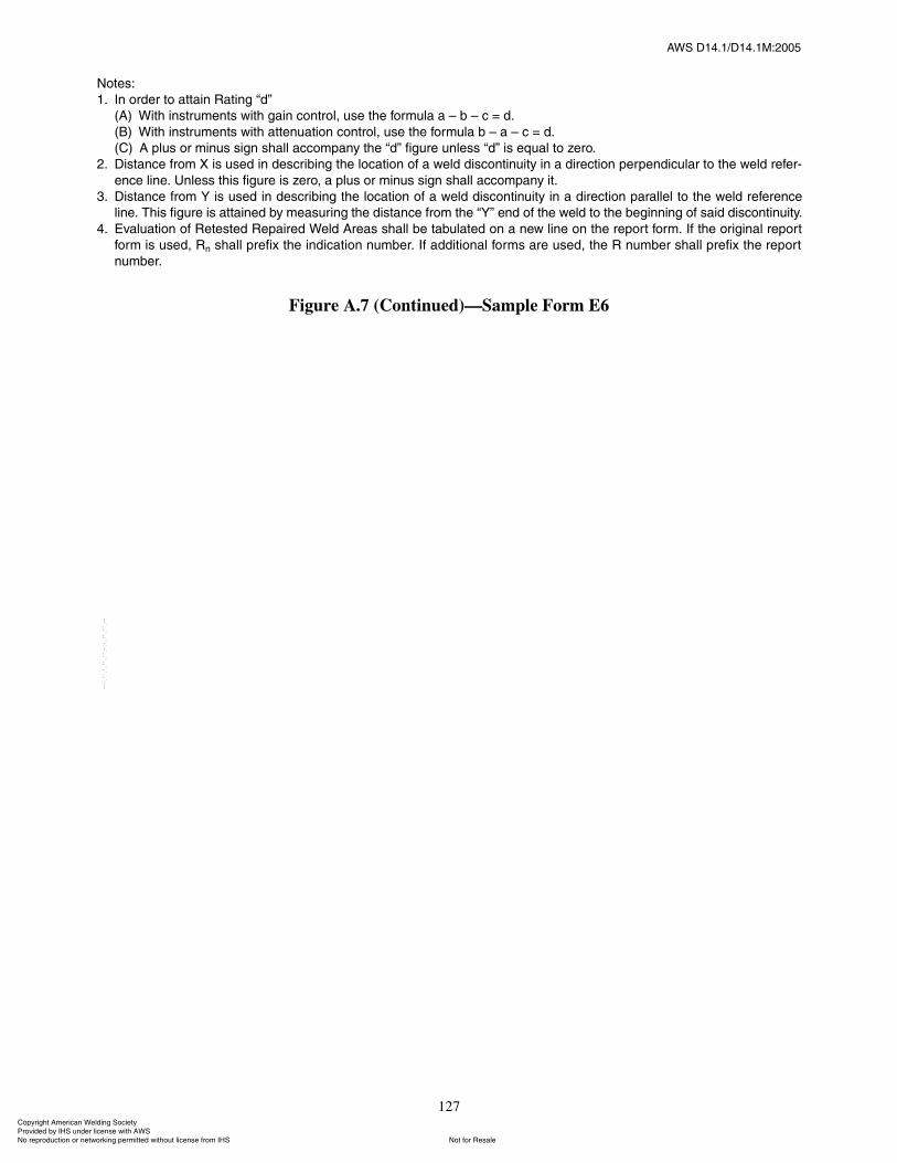
ßÉÍ ÜïìòïñÜïìòïÓæîððë
127
Ò±¬»æ
ïò ײ ±®¼»® ¬± ¿¬¬¿·² ο¬·²¹ �¼�
øß÷ É·¬¸ ·²¬®«³»²¬ ©·¬¸ ¹¿·² ½±²¬®±´ô «» ¬¸» º±®³«´¿ ¿ � ¾ � ½ ã ¼ò
øÞ÷ É·¬¸ ·²¬®«³»²¬ ©·¬¸ ¿¬¬»²«¿¬·±² ½±²¬®±´ô «» ¬¸» º±®³«´¿ ¾ � ¿ � ½ ã ¼ò
øÝ÷ ß °´« ±® ³·²« ·¹² ¸¿´´ ¿½½±³°¿²§ ¬¸» �¼� º·¹«®» «²´» �¼� · »¯«¿´ ¬± ¦»®±ò
îò Ü·¬¿²½» º®±³ È · «»¼ ·² ¼»½®·¾·²¹ ¬¸» ´±½¿¬·±² ±º ¿ ©»´¼ ¼·½±²¬·²«·¬§ ·² ¿ ¼·®»½¬·±² °»®°»²¼·½«´¿® ¬± ¬¸» ©»´¼ ®»º»®ó
»²½» ´·²»ò ˲´» ¬¸· º·¹«®» · ¦»®±ô ¿ °´« ±® ³·²« ·¹² ¸¿´´ ¿½½±³°¿²§ ·¬ò
íò Ü·¬¿²½» º®±³ Ç · «»¼ ·² ¼»½®·¾·²¹ ¬¸» ´±½¿¬·±² ±º ¿ ©»´¼ ¼·½±²¬·²«·¬§ ·² ¿ ¼·®»½¬·±² °¿®¿´´»´ ¬± ¬¸» ©»´¼ ®»º»®»²½»
´·²»ò ̸· º·¹«®» · ¿¬¬¿·²»¼ ¾§ ³»¿«®·²¹ ¬¸» ¼·¬¿²½» º®±³ ¬¸» �Ç� »²¼ ±º ¬¸» ©»´¼ ¬± ¬¸» ¾»¹·²²·²¹ ±º ¿·¼ ¼·½±²¬·²«·¬§ò
ìò Ûª¿´«¿¬·±² ±º 묻¬»¼ λ°¿·®»¼ É»´¼ ß®»¿ ¸¿´´ ¾» ¬¿¾«´¿¬»¼ ±² ¿ ²»© ´·²» ±² ¬¸» ®»°±®¬ º±®³ò ׺ ¬¸» ±®·¹·²¿´ ®»°±®¬
º±®³ · «»¼ô β ¸¿´´ °®»º·¨ ¬¸» ·²¼·½¿¬·±² ²«³¾»®ò ׺ ¿¼¼·¬·±²¿´ º±®³ ¿®» «»¼ô ¬¸» Î ²«³¾»® ¸¿´´ °®»º·¨ ¬¸» ®»°±®¬
²«³¾»®ò
Figure A.7 (Continued)�Sample Form E6
ݱ°§®·¹¸¬ ß³»®·½¿² É»´¼·²¹ ͱ½·»¬§ Ю±ª·¼»¼ ¾§ ×ØÍ «²¼»® ´·½»²» ©·¬¸ ßÉÍ
Ò±¬ º±® λ¿´»Ò± ®»°®±¼«½¬·±² ±® ²»¬©±®µ·²¹ °»®³·¬¬»¼ ©·¬¸±«¬ ´·½»²» º®±³ ×ØÍ
óóÀôôÀôôÀóÀóÀôôÀôôÀôÀôôÀóóó

ßÉÍ ÜïìòïñÜïìòïÓæîððë
128
Ô×ÏË×Ü ÐÛÒÛÌÎßÒÌ ×ÒÍÐÛÝÌ×ÑÒ ÎÛÐÑÎÌ
Ý«¬±³»® ÁÁÁÁÁÁÁÁÁÁÁÁÁÁÁÁÁÁÁÁÁÁÁÁÁÁÁÁÁÁÁÁÁÁÁÁ Ü¿¬» ÁÁÁÁÁÁÁÁÁÁÁÁÁÁÁÁÁÁÁÁÁÁÁÁÁÁÁÁÁÁÁÁÁÁÁÁÁÁÁÁÁ
Ñ®¼»® Ò±ò ÁÁÁÁÁÁÁÁÁÁÁÁÁÁÁÁÁÁÁÁÁÁÁÁÁÁÁÁÁÁÁÁÁÁÁÁ Ó¿¬»®·¿´ ÁÁÁÁÁÁÁÁÁÁÁÁÁÁÁÁÁÁÁÁÁÁÁÁÁÁÁÁÁÁÁÁÁÁÁÁÁÁ
Ü©¹ò Ò±ò ÁÁÁÁÁÁÁÁÁÁÁÁÁÁÁÁÁÁÁÁÁÁÁÁÁÁÁÁÁÁÁÁÁÁÁÁÁ Í°»½·º·½¿¬·±²ÁÁÁÁÁÁÁÁÁÁÁÁÁÁÁÁÁÁÁÁÁÁÁÁÁÁÁÁÁÁÁÁÁÁÁ
Ú±®ÁÁÁÁÁÁÁÁÁÁÁÁÁÁÁÁÁÁÁÁÁÁÁÁÁÁÁÁÁÁÁÁÁÁÁÁÁÁÁÁÁÁ
ͱ¿µ Ì·³»ÁÁÁÁÁÁÁÁÁÁÁÁÁÁÁÁÁÁÁÁÁÁÁÁÁÁÁÁÁÁÁÁÁÁÁÁ
̸» ¿¾±ª» °¿®¬ ¸¿ª» ¾»»² ½¿®»º«´´§ ¬»¬»¼ ©·¬¸ ´·¯«·¼ °»²»¬®¿²¬ò ̸· ·²°»½¬·±² · ´·³·¬»¼ ¬± ¼»º»½¬ ±º ¬¸» ¬§°» ©¸·½¸
½¿² ²±®³¿´´§ ¾» ´±½¿¬»¼ ©·¬¸ ¬¸» ´·¯«·¼ °»²»¬®¿²¬ ·²°»½¬·±² ³»¬¸±¼ò
ÁÁÁÁÁÁÁÁÁÁÁÁÁÁÁÁÁÁÁÁÁÁÁÁÁÁÁÁÁÁÁÁÁÁÁÁÁÁÁÁÁÁÁÁÁ
ÁÁÁÁÁÁÁÁÁÁÁÁÁÁÁÁÁÁÁÁÁÁÁÁÁÁÁÁÁÁÁÁÁÁÁÁÁÁÁÁÁÁÁÁÁ
Figure A.8�Sample Form E7
з»½» Ü»½®·°¬·±² ݱ³³»²¬
ݱ°§®·¹¸¬ ß³»®·½¿² É»´¼·²¹ ͱ½·»¬§ Ю±ª·¼»¼ ¾§ ×ØÍ «²¼»® ´·½»²» ©·¬¸ ßÉÍ
Ò±¬ º±® λ¿´»Ò± ®»°®±¼«½¬·±² ±® ²»¬©±®µ·²¹ °»®³·¬¬»¼ ©·¬¸±«¬ ´·½»²» º®±³ ×ØÍ
óóÀôôÀôôÀóÀóÀôôÀôôÀôÀôôÀóóó
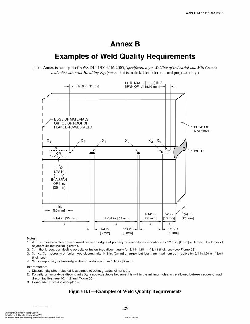
ßÉÍ ÜïìòïñÜïìòïÓæîððë
129
ß²²»¨ Þ
Û¨¿³°´» ±º É»´¼ Ï«¿´·¬§ λ¯«·®»³»²¬
(This Annex is not a part of AWS D14.1/D14.1M:2005, Specification for Welding of Industrial and Mill Cranesand other Material Handling Equipment, but is included for informational purposes only.)
Ò±¬»æïò ß�¬¸» ³·²·³«³ ½´»¿®¿²½» ¿´´±©»¼ ¾»¬©»»² »¼¹» ±º °±®±·¬§ ±® º«·±²ó¬§°» ¼·½±²¬·²«·¬·» ïñïê ·²ò Åî ³³Ã ±® ´¿®¹»®ò ̸» ´¿®¹»® ±º
¿¼¶¿½»²¬ ¼·½±²¬·²«·¬·» ¹±ª»®²òîò Èï �¬¸» ´¿®¹»¬ °»®³··¾´» °±®±·¬§ ±® º«·±²ó¬§°» ¼·½±²¬·²«·¬§ º±® íñì ·²ò Åî𠳳à ¶±·²¬ ¬¸·½µ²» ø»» Ú·¹«®» íë÷ò
íò Èî ô Èí ô Èì �°±®±·¬§ ±® º«·±²ó¬§°» ¼·½±²¬·²«·¬§ ïñïê ·²ò Åî ³³Ã ±® ´¿®¹»®ô ¾«¬ ´» ¬¸¿² ³¿¨·³«³ °»®³··¾´» º±® íñì ·²ò Åî𠳳à ¶±·²¬
¬¸·½µ²»òìò Èë ô Èê �°±®±·¬§ ±® º«·±²ó¬§°» ¼·½±²¬·²«·¬§ ´» ¬¸¿² ïñïê ·²ò Åî ³³Ãò
ײ¬»®°®»¬¿¬·±²æïò Ü·½±²¬·²«·¬§ ·¦» ·²¼·½¿¬»¼ · ¿«³»¼ ¬± ¾» ·¬ ¹®»¿¬»¬ ¼·³»²·±²òîò б®±·¬§ ±® º«·±²ó¬§°» ¼·½±²¬·²«·¬§ Èì · ²±¬ ¿½½»°¬¿¾´» ¾»½¿«» ·¬ · ©·¬¸·² ¬¸» ³·²·³«³ ½´»¿®¿²½» ¿´´±©»¼ ¾»¬©»»² »¼¹» ±º «½¸
¼·½±²¬·²«·¬·» ø»» ïðòïïòî ¿²¼ Ú·¹«®» íë÷òíò λ³¿·²¼»® ±º ©»´¼ · ¿½½»°¬¿¾´»ò
Figure B.1�Examples of Weld Quality Requirements
ݱ°§®·¹¸¬ ß³»®·½¿² É»´¼·²¹ ͱ½·»¬§ Ю±ª·¼»¼ ¾§ ×ØÍ «²¼»® ´·½»²» ©·¬¸ ßÉÍ
Ò±¬ º±® λ¿´»Ò± ®»°®±¼«½¬·±² ±® ²»¬©±®µ·²¹ °»®³·¬¬»¼ ©·¬¸±«¬ ´·½»²» º®±³ ×ØÍ
óóÀôôÀôôÀóÀóÀôôÀôôÀôÀôôÀóóó

130
ßÉÍ ÜïìòïñÜïìòïÓæîððë
This page is intentionally blank.
ݱ°§®·¹¸¬ ß³»®·½¿² É»´¼·²¹ ͱ½·»¬§ Ю±ª·¼»¼ ¾§ ×ØÍ «²¼»® ´·½»²» ©·¬¸ ßÉÍ
Ò±¬ º±® λ¿´»Ò± ®»°®±¼«½¬·±² ±® ²»¬©±®µ·²¹ °»®³·¬¬»¼ ©·¬¸±«¬ ´·½»²» º®±³ ×ØÍ
óóÀôôÀôôÀóÀóÀôôÀôôÀôÀôôÀóóó
ßÉÍ ÜïìòïñÜïìòïÓæîððë
131
C1. IntroductionThe AWS Board of Directors has adopted a policy
whereby all official interpretations of AWS standardswill be handled in a formal manner. Under that policy, allinterpretations are made by the committee that is respon-sible for the standard. Official communication concern-ing an interpretation is through the AWS staff memberwho works with that committee. The policy requires thatall requests for an interpretation be submitted in writing.Such requests will be handled as expeditiously as possi-ble, but due to the complexity of the work and the proce-dures that must be followed, some interpretations mayrequire considerable time.
C2. ProcedureAll inquiries shall be directed to:
Managing Director, Technical ServicesAmerican Welding Society550 N.W. LeJeune RoadMiami, FL 33126
All inquiries shall contain the name, address, andaffiliation of the inquirer, and they shall provide enoughinformation for the committee to fully understand thepoint of concern in the inquiry. If that point is not clearlydefined, the inquiry will be returned for clarification. Forefficient handling, all inquiries should be typewritten andshould also be in the format used here.
C2.1 Scope. Each inquiry shall address one single provi-sion of the standard, unless the point of the inquiryinvolves two or more interrelated provisions. That provi-sion shall be identified in the scope of the inquiry, along
with the edition of the standard that contains the provi-sions or that the inquirer is addressing.
C2.2 Purpose of the Inquiry. The purpose of theinquiry shall be stated in this portion of the inquiry. Thepurpose can be either to obtain an interpretation of astandard�s requirement, or to request the revision of aparticular provision in the standard.
C2.3 Content of the Inquiry. The inquiry should beconcise, yet complete, to enable the committee to quicklyand fully understand the point of the inquiry. Sketchesshould be used when appropriate and all paragraphs, fig-ures, tables, or Annexes, which bear on the inquiry shallbe cited. If the point of the inquiry is to obtain a revisionof the standard, the inquiry shall provide technical justi-fication for that revision.
C2.4 Proposed Reply. The inquirer should, as a pro-posed reply, state an interpretation of the provision thatis the point of the inquiry, or the wording for a proposedrevision, if that is what inquirer seeks.
C3. Interpretation of Provisions of the Standard
Interpretations of provisions of the standard are madeby the relevant AWS Technical Committee. The secre-tary of the committee refers all inquiries to the Chair ofthe particular subcommittee that has jurisdiction over theportion of the standard addressed by the inquiry. Thesubcommittee reviews the inquiry and the proposed replyto determine what the response to the inquiry should be.Following the subcommittee�s development of theresponse, the inquiry and the response are presented tothe entire committee for review and approval. Upon
ß²²»¨ Ý
Ù«·¼»´·²» º±® Ю»°¿®¿¬·±² ±º Ì»½¸²·½¿´ ײ¯«·®·»º±® ßÉÍ Ì»½¸²·½¿´ ݱ³³·¬¬»»
(This Annex is not a part of AWS D14.1/D14.1M:2005, Specification for Welding of Industrial and Mill Cranesand Other Material Handling Equipment, but is included for informational purposes only.)
ݱ°§®·¹¸¬ ß³»®·½¿² É»´¼·²¹ ͱ½·»¬§ Ю±ª·¼»¼ ¾§ ×ØÍ «²¼»® ´·½»²» ©·¬¸ ßÉÍ
Ò±¬ º±® λ¿´»Ò± ®»°®±¼«½¬·±² ±® ²»¬©±®µ·²¹ °»®³·¬¬»¼ ©·¬¸±«¬ ´·½»²» º®±³ ×ØÍ
óóÀôôÀôôÀóÀóÀôôÀôôÀôÀôôÀóóó
ßÉÍ ÜïìòïñÜïìòïÓæîððë
132
approval by the committee, the interpretation will be anofficial interpretation of the Society, and the secretarywill transmit the response to the inquirer and to the Weld-ing Journal for publication.
C4. Publication of InterpretationsAll official interpretations will appear in the Welding
Journal.
C5. Telephone InquiriesTelephone inquiries to AWS headquarters concerning
AWS standards should be limited to questions of a gen-eral nature or to matters directly related to the use of thestandard. The Board of Directors� policy requires that allAWS staff members respond to a telephone request foran official interpretation of any AWS standard with theinformation that such an interpretation can be obtained
only through a written request. The AWS headquartersstaff cannot provide consulting services. The staff can,however, refer a caller to any of those consultants whosenames are on file at AWS headquarters.
C6. The AWS Technical CommitteeThe activities of AWS Technical Committees in
regard to interpretations are limited strictly to the inter-pretation of provisions of standards prepared by theCommittee or to consideration of revisions to existingprovisions on the basis of new data or technology. Nei-ther the Committee nor the staff is in a position to offerinterpretive or consulting services on: (1) specific engi-neering problems; or (2) requirements of standardsapplied to fabrications outside the scope of the documentor points not specifically covered by the standard. Insuch cases, the inquirer should seek assistance from acompetent engineer experienced in the particular field ofinterest.
ݱ°§®·¹¸¬ ß³»®·½¿² É»´¼·²¹ ͱ½·»¬§ Ю±ª·¼»¼ ¾§ ×ØÍ «²¼»® ´·½»²» ©·¬¸ ßÉÍ
Ò±¬ º±® λ¿´»Ò± ®»°®±¼«½¬·±² ±® ²»¬©±®µ·²¹ °»®³·¬¬»¼ ©·¬¸±«¬ ´·½»²» º®±³ ×ØÍ
óóÀôôÀôôÀóÀóÀôôÀôôÀôÀôôÀóóó
ßÉÍ ÜïìòïñÜïìòïÓæîððë
133
D1. American Welding Society (AWS) References
(1) AWS A1.1, Metric Practice Guide for the Weld-ing Industry
(2) AWS A5.17/5.17M-97, Specification for CarbonSteel Electrodes and Fluxes for Submerged Arc Welding
(3) AWS C3.2, Standard Method for Evaluating theStrength of Brazed Joints in Shear
(4) AWS D1.1, Structural Welding Code�Steel(5) AWS D15.2, Recommended Practice for the
Welding of Rails and Related Rail Components for Useby Rail Vehicles
(6) AWS F4.1, Recommended Safe Practices for thePreparation for Welding and Cutting of Containers andPiping That Have Held Hazardous Substances
D2. American Association of State Highway & Transportation Officials (AASHTO)
(1) Standard Specifications for Highway Bridges
D3. American National Standards Institute (ANSI)
(1) ANSI Z87.1, Practice for Occupational andEducational Eye and Face Protection
(2) ANSI Z49.1, Safety in Welding, Cutting, andAllied Processes (Published by AWS)
D4. American Society ofMechanical Engineers (ASME) Standards
(1) ASME Boiler and Pressure Vessel Code, SectionIX, Qualification Standard for Welding and BrazingProcedures, Welders, Brazers, and Welding and BrazingOperators
D5. Canadian Standards Association (CSA)
(1) W178.2, Certification of Welding Inspectors
ß²²»¨ Ü
Þ·¾´·±¹®¿°¸§
(This Annex is not a part of AWS D14.1/D14.1M:2005, Specification for Welding of Industrial and Mill Cranesand Other Material Handling Equipment, but is included for informational purposes only.)
ݱ°§®·¹¸¬ ß³»®·½¿² É»´¼·²¹ ͱ½·»¬§ Ю±ª·¼»¼ ¾§ ×ØÍ «²¼»® ´·½»²» ©·¬¸ ßÉÍ
Ò±¬ º±® λ¿´»Ò± ®»°®±¼«½¬·±² ±® ²»¬©±®µ·²¹ °»®³·¬¬»¼ ©·¬¸±«¬ ´·½»²» º®±³ ×ØÍ
óóÀôôÀôôÀóÀóÀôôÀôôÀôÀôôÀóóó

134
ßÉÍ ÜïìòïñÜïìòïÓæîððë
This page is intentionally blank.
ݱ°§®·¹¸¬ ß³»®·½¿² É»´¼·²¹ ͱ½·»¬§ Ю±ª·¼»¼ ¾§ ×ØÍ «²¼»® ´·½»²» ©·¬¸ ßÉÍ
Ò±¬ º±® λ¿´»Ò± ®»°®±¼«½¬·±² ±® ²»¬©±®µ·²¹ °»®³·¬¬»¼ ©·¬¸±«¬ ´·½»²» º®±³ ×ØÍ
óóÀôôÀôôÀóÀóÀôôÀôôÀôÀôôÀóóó
ßÉÍ ÜïìòïñÜïìòïÓæîððë
135
Ô·¬ ±º ßÉÍ Ü±½«³»²¬ ±² Ó¿½¸·²»®§ ¿²¼ Û¯«·°³»²¬
Designation Title
D14.1/D14.1M Specification for Welding of Industrial and Mill Cranes and Other Material Handling Equipment
D14.3/D14.3M Specification for Welding Earthmoving and Construction Equipment
D14.4/D14.4M Specification for Welded Joints in Machinery and Equipment
D14.5 Specification for Welding of Presses and Press Components
D14.6/D14.6M Specification for Welding of Rotating Elements of Equipment
ݱ°§®·¹¸¬ ß³»®·½¿² É»´¼·²¹ ͱ½·»¬§ Ю±ª·¼»¼ ¾§ ×ØÍ «²¼»® ´·½»²» ©·¬¸ ßÉÍ
Ò±¬ º±® λ¿´»Ò± ®»°®±¼«½¬·±² ±® ²»¬©±®µ·²¹ °»®³·¬¬»¼ ©·¬¸±«¬ ´·½»²» º®±³ ×ØÍ
óóÀôôÀôôÀóÀóÀôôÀôôÀôÀôôÀóóó

136
ßÉÍ ÜïìòïñÜïìòïÓæîððë
This page is intentionally blank.
ݱ°§®·¹¸¬ ß³»®·½¿² É»´¼·²¹ ͱ½·»¬§ Ю±ª·¼»¼ ¾§ ×ØÍ «²¼»® ´·½»²» ©·¬¸ ßÉÍ
Ò±¬ º±® λ¿´»Ò± ®»°®±¼«½¬·±² ±® ²»¬©±®µ·²¹ °»®³·¬¬»¼ ©·¬¸±«¬ ´·½»²» º®±³ ×ØÍ
óóÀôôÀôôÀóÀóÀôôÀôôÀôÀôôÀóóó
ݱ°§®·¹¸¬ ß³»®·½¿² É»´¼·²¹ ͱ½·»¬§ Ю±ª·¼»¼ ¾§ ×ØÍ «²¼»® ´·½»²» ©·¬¸ ßÉÍ
Ò±¬ º±® λ¿´»Ò± ®»°®±¼«½¬·±² ±® ²»¬©±®µ·²¹ °»®³·¬¬»¼ ©·¬¸±«¬ ´·½»²» º®±³ ×ØÍ
óóÀôôÀôôÀóÀóÀôôÀôôÀôÀôôÀóóó