I-90 and Rattlesnake Area
26
Transcript of I-90 and Rattlesnake Area


I-90 and Rattlesnake Area -Missoula, MT
• I-90 first constructed in Missoula 1966 and 1967.
• When I-90 built, homes (mansions!) were moved from this location to build it.
• Rattlesnake neighborhoods extend up canyon.
• Mt Jumbo is a significant geographic feature.
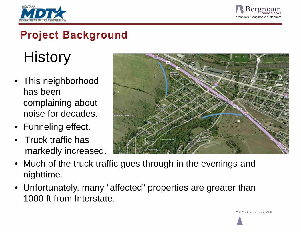
• Much of the truck traffic goes through in the evenings and nighttime.
• Unfortunately, many “affected” properties are greater than 1000 ft from Interstate.
• This neighborhood has been complaining about noise for decades.
• Funneling effect.• Truck traffic has
markedly increased.
History

Survey Responses 2008
• On-line and mail-in survey options• Notices hand-delivered to neighborhood• Response Rate was 56%• Rate of return for renters was 8%• Of respondents, 73% in favor of barriers• Weighting didn’t exist in our policy then
Comments to polling
• Those opposed are concerned about cost to taxpayer and blocked views and blocked light
• Proponents are concerned about aesthetics; but believe dust and noise reduced; property values will increased.

• Updated Traffic Noise Analysis in 2012
• Procedures conform to the requirements developed by the Federal Highway Administration (FHWA)
• Chapter I of Title 23, Code of Federal Regulations, Part 772 (23 CFR 772), Procedures for Abatement of Highway Traffic Noise and Construction Noise
• Montana Department of Transportation (MDT) document Traffic Noise Analysis and Abatement Policy (Effective 7/1/2011)

• Review of Existing Activities (land use) and Perform Noise Measurements

• Predict Future Loudest Hour Traffic Noise Levels -TNM Modeling

• Determine Traffic Noise Impacts & Evaluates Noise Abatement Alternatives
EVALUATED NOISE BARRIER OPTIONS
Noise BarrierOptions
Structure Mounted Noise Wall on
Van Buren Bridge Over I-90
Existing Leq (1hr)
Noise Levels, dB(A)
Range of Future Leq(1hr) Noise Levels, dB(A)
Max. N
oise Reduction
(dB(A))
Barrier Characteristics
w/o Barrier
With Barrier
Approx.Length
(ft)
Avg. Height
(ft)1
2
YES
NO
55-66
55-66
57-68
57-68
53-64
53-64
10
9
3014
2847
13.2
13.3

• Recommend Noise Walls for Construction –MDT “Feasible and Reasonable” Criteria
NOISE BARRIER FEASIBILITY AND REASONABLENESS
1st Row Impacted Receptors 1st Row Benefited Receptors
Noise Barrier O
ption
Total Noise
Reduction > 5 dB(A)
% of Total with Noise Reduction > 5 dB(A)
Total Noise
Reduction >7 dB(A)
% of Total with Noise Reduction >7 dB(A)
Max.Allow
CEI CEI
Feasible (Y / N)
Reasonable (Y / N)
1 18 18 100% 29 20 69% $5,600 $5,075 Y Y2 18 15 83% 26 17 65% $4,900 $7,745 Y N

• Coordination with Local Officials & Review of Construction Noise
INFORMATION FOR LOCAL OFFICIALSRecommended Distance Needed from the Highway Median
to a Specified Leq Noise Level (ft)
Location
Human Activity is Predominately
Outdoor (or Indoor and Building
Provides 20 dB(A) Reduction)
Higher Allowable Planning Level Goal
(2)
60 dB(A) 64 dB(A)Main Highway Segment Limits Main Hwy.W. Greenough (west limit) to
Dead End of Vine Street (east limit) I-90 350 250

• MDT Highway Design Group already in final design phase developing highway features prior to final noise wall study.

• MDT Extends Contract with Bergmann to develop Design Plans, Specifications, and Estimate for Noise Wall Portion of the Project

• Noise Wall - Line and Grade Process

• Supplemental Survey

• Sub-Surface Exploration

• Example of Failure when a proper Sub-Surface Exploration Plan is not developed.

• TNM Noise Wall Optimization Process• Use 1-ft high increments, to obtain the most cost-effective design that provides optimal
acoustical effectiveness;
• Provide a smooth top of noise barrier profile that limits the steps up or down in the noisebarrier at the posts to a maximum of 1 foot;
• Provide an upward adjustment in the noise barrier height (not top-elevation) to accountfor narrow shoulder and/or steep embankment slopes in fill sections;
• Consider above ground (i.e. trees, light poles, etc.) and underground (utilities, etc.)features that cannot be removed or relocated when setting barrier alignment;
• Set the start point of the Main Line Barrier such that the WB On-Ramp motorist has thenecessary unobstructed view of traffic on I-90 WB to the motorist’s left;
• Ensure that the noise barrier is high enough to break the line of sight between benefitedreceivers and truck exhaust stacks in all lanes; and
• Consider the possible adverse effects of single reflections on receivers located on theother side of the roadway (or in the case of parallel noise barriers the effects of parallelnoise barrier degradation)

• Example of two different outcomes during process of determining Top-of-Wall Elevation

Structural Calculations
Ground Mounted Bridge Mounted

Coordination with Highway Designers

Preliminary Plan and Profile Design Drawings

Structures Design Drawings

Drawing Plan Details

Drawing Plan Details

Photo Simulations