
I-84 Lateral Slide Field Pilot...
32
SHRP 2 Renewal Project R04 I-84 Lateral Slide Field Pilot Project
Transcript of I-84 Lateral Slide Field Pilot...

SHRP 2 Renewal Project R04
I-84 Lateral Slide Field Pilot Project
SHRP 2 Renewal Project R04
I-84 Lateral Slide Field Pilot Project
TRANSPORTATION RESEARCH BOARD Washington, D.C.
2014 www.TRB.org

© 2014 National Academy of Sciences. All rights reserved. ACKNOWLEDGMENT This work was sponsored by the Federal Highway Administration in cooperation with the American Association of State Highway and Transportation Officials. It was conducted in the second Strategic Highway Research Program, which is administered by the Transportation Research Board of the National Academies. COPYRIGHT INFORMATION Authors herein are responsible for the authenticity of their materials and for obtaining written permissions from publishers or persons who own the copyright to any previously published or copyrighted material used herein. The second Strategic Highway Research Program grants permission to reproduce material in this publication for classroom and not-for-profit purposes. Permission is given with the understanding that none of the material will be used to imply TRB, AASHTO, or FHWA endorsement of a particular product, method, or practice. It is expected that those reproducing material in this document for educational and not-for-profit purposes will give appropriate acknowledgment of the source of any reprinted or reproduced material. For other uses of the material, request permission from SHRP 2. NOTICE The project that is the subject of this document was a part of the second Strategic Highway Research Program, conducted by the Transportation Research Board with the approval of the Governing Board of the National Research Council. The Transportation Research Board of the National Academies, the National Research Council, and the sponsors of the second Strategic Highway Research Program do not endorse products or manufacturers. Trade or manufacturers’ names appear herein solely because they are considered essential to the object of the report. DISCLAIMER The opinions and conclusions expressed or implied in this document are those of the researchers who performed the research. They are not necessarily those of the second Strategic Highway Research Program, the Transportation Research Board, the National Research Council, or the program sponsors. The information contained in this document was taken directly from the submission of the authors. This material has not been edited by the Transportation Research Board. SPECIAL NOTE: This document IS NOT an official publication of the second Strategic Highway Research Program, the Transportation Research Board, the National Research Council, or the National Academies.

The National Academy of Sciences is a private, nonprofit, self-perpetuating society of distinguished scholars engaged in scientific and engineering research, dedicated to the furtherance of science and technology and to their use for the general welfare. On the authority of the charter granted to it by Congress in 1863, the Academy has a mandate that requires it to advise the federal government on scientific and technical matters. Dr. Ralph J. Cicerone is president of the National Academy of Sciences.
The National Academy of Engineering was established in 1964, under the charter of the National Academy of Sciences, as a parallel organization of outstanding engineers. It is autonomous in its administration and in the selection of its members, sharing with the National Academy of Sciences the responsibility for advising the federal government. The National Academy of Engineering also sponsors engineering programs aimed at meeting national needs, encourages education and research, and recognizes the superior achievements of engineers. Dr. C. D. (Dan) Mote, Jr., is president of the National Academy of Engineering.
The Institute of Medicine was established in 1970 by the National Academy of Sciences to secure the services of eminent members of appropriate professions in the examination of policy matters pertaining to the health of the public. The Institute acts under the responsibility given to the National Academy of Sciences by its congressional charter to be an adviser to the federal government and, upon its own initiative, to identify issues of medical care, research, and education. Dr. Harvey V. Fineberg is president of the Institute of Medicine.
The National Research Council was organized by the National Academy of Sciences in 1916 to associate the broad community of science and technology with the Academy’s purposes of furthering knowledge and advising the federal government. Functioning in accordance with general policies determined by the Academy, the Council has become the principal operating agency of both the National Academy of Sciences and the National Academy of Engineering in providing services to the government, the public, and the scientific and engineering communities. The Council is administered jointly by both Academies and the Institute of Medicine. Dr. Ralph J. Cicerone and Dr. C.D. (Dan) Mote, Jr., are chair and vice chair, respectively, of the National Research Council. The Transportation Research Board is one of six major divisions of the National Research Council. The mission of the Transportation Research Board is to provide leadership in transportation innovation and progress through research and information exchange, conducted within a setting that is objective, interdisciplinary, and multimodal. The Board’s varied activities annually engage about 7,000 engineers, scientists, and other transportation researchers and practitioners from the public and private sectors and academia, all of whom contribute their expertise in the public interest. The program is supported by state transportation departments, federal agencies including the component administrations of the U.S. Department of Transportation, and other organizations and individuals interested in the development of transportation. www.TRB.org
www.national-academies.org

TABLE OF CONTENTS 1. INTRODUCTION 2. PILOT PROJECT DESCRIPTION 3. PILOT PROJECT INNOVATIVE FEATURES 4. PILOT PROJECT CONSTRUCTION
4.1. PREBID MEETING 4.2. CONTRACTOR BIDS 4.3. PRECONSTRUCTION MEETING 4.4. SITE PREPARATION 4.5. PRECAST ELEMENT FABRICATION
4.5.1. NEXT Beam 4.5.2. End Diaphragms 4.5.3. Approach Slabs 4.5.4. Sleeper Slabs
4.6. ABUTMENT CONSTRUCTION TO SLIDE ELEVATION 4.6.1. Drilled Shafts 4.6.2. Columns, Walls, and Cap Beams 4.6.3. T-Walls
4.7. ASBESTOS ABATEMENT 4.8. TEMPORARY FALSEWORK AND TEMPORARY CRANE PLATFORMS 4.9. SUPERSTRUCTURE AND APPROACH SLAB ERECTION
4.9.1. End Diaphragm, NEXT Beams, and Approach Slabs 4.9.2. UHPC Closure Pours 4.9.3. Concrete Barriers, Waterproofing, Tack Coat Application, and Sleeper Slabs
4.10. TRIAL SLIDE 4.11. ABC PERIOD 4.12. ABC TIME FRAME AND SCHEDULE
4.12.1. Demolition of Existing Bridge 4.12.2. Approach Roadway 4.12.3. Lateral Slide
4.13. POST-ABC CONSTRUCTION ACTIVITIES 5. PROJECT SHOWCASE 6. PUBLIC OUTREACH
6.1. NYSDOT PROJECT WEBSITE 7. SHRP 2 R04 VIDEO DOCUMENTARY 8. LESSONS LEARNED
8.1. ADMINISTRATIVE CHALLENGES AND EXPEDITED REVIEW TIMES 8.2. CONCRETE MIX DESIGN 8.3. PTFE SLIDE BEARINGS 8.4. NEXT BEAM CAMBER
9. CONCLUSION

1. Introduction
Accelerated bridge construction (ABC) techniques have the potential to minimize traffic disruptions during bridge renewals, promote traffic and worker safety, and improve the overall quality and durability of bridges. Minimizing road closures and traffic disruptions are key objectives. ABC entails prefabricating as many of the bridge components as feasible. The successful use of prefabricated elements to accelerate construction requires a careful evaluation of the requirements for the bridge, site constraints, and an unbiased review of the total costs and benefits. For ABC systems to be viable and see greater acceptance, the savings in construction time should be clearly demonstrated.
The SHRP 2 Project R04, Innovative Bridge Designs for Rapid Renewal, takes the approach that ABC designs should allow maximum opportunities for the general contractor to do its own prefabrication and erection. The R04 team focused on specific strategies for ABC systems. To be successful, projects must be designed to be as light as possible, as simple as possible, and as simple-to-erect as possible.
The ABC design concepts developed as part of the SHRP 2 R04 project have been classified into three tiers according to implementation duration:
• Tier 1—Bridge Move—ABC concepts that can be completed over a weekend closure;
• Tier 2—Modular Construction—ABC concepts that can be completed in a few weeks; and
• Tier 3—Statewide ABC Bridge Program—ABC concepts that accelerate larger, systemwide projects, and save months and/or years on the overall schedule.
Modular bridge systems are particularly suited to Tier 1 concepts, such as weekend bridge replacements, or Tier 2 concepts, in which the entire bridge may be scheduled for replacement in a 1- to 2-week period using a detour to maintain traffic. Tier 1 concepts include preassembled bridges, completed at an off-alignment location and then moved by various methods into the final location using techniques such as lateral sliding, rolling, skidding, incremental launching, and movement and placement using self-propelled modular transporters (SPMT). Tier 3 involves accelerating a statewide bridge renewal program by months or years by applying Tier 1 and Tier 2 ABC technologies.
SHRP 2 Project R04, with HNTB as the prime contractor, was composed of three distinct phases over a 4-year period, beginning in 2008. During Phase I, completed in November 2009, the team collected extensive data on ABC projects and identified current impediments and challenges to greater use of ABC by bridge owners. In Phase II, completed between December 1, 2009, and December 31, 2010, the findings and ABC concepts from Phase I were subjected to critical evaluations to identify concepts that could be advanced to ABC standard plans in Phase III. Phase III (January 1, 2011, to March 2012) also included the construction of the first ABC demonstration project, which was designed under Phase II, utilizing the modular ABC systems. The principal objective of the demonstration project was to demolish and replace the existing bridge within the 14-day ABC period.
Modular components were erected and connected via closure pours of ultra-high-performance concrete (UHPC), which achieves high strength in a short period of time. Several different areas of testing needs for UHPC joints were identified during the design of the demonstration project. The testing of UHPC joints was performed by Iowa State University, a member of the R04 team. The testing covered the constructability and grindability of the UHPC joints and the negative bending strength of the transverse pier joints.
A key objective of the SHRP 2 R04 project was to develop “standardized approaches to designing and

constructing complete bridge systems for rapid renewals.” The aim therefore was to develop pre-engineered standards for modular bridge substructure and superstructure systems that can be installed with minimal traffic disruptions in renewal applications. The three phases of Project R04 culminated with the development of the ABC Toolkit: Innovative Bridge Designs for Rapid Renewal. The toolkit developed for prefabricated elements and modular systems in the R04 project comprises ABC standard plans, ABC design examples, recommended ABC design specifications (load and resistance factor design, or LRFD), and recommended ABC construction specifications (LRFD).
Standard plans include details for precast modular abutment systems, precast pier systems, modular superstructure systems, and erection systems and techniques. The toolkit includes typical ABC details for superstructure and substructure systems for routine bridges that are suitable for a range of spans. Erection analysis and methodology was developed by Genesis Structures, Inc., a member of the SHRP 2 R04 team.
The detailed design examples developed for use by future designers provide step-by-step guidance on the overall structural design of the prefabricated bridge elements and systems. The design examples pertain to the same standard bridge configurations for steel and concrete used in the ABC standard plans. The intent of the toolkit is to provide design examples that can be used in conjunction with the ABC standard plans so that the practitioner new to ABC will get a comprehensive look at how ABC designs are carried out and translated into design drawings and details.
LRFD Bridge Design Specifications do not explicitly deal with the unique aspects of large-scale prefabrication, including issues such as element interconnection, system strength, and behavior of rapid deployment systems during construction. Thus, the R04 project also entailed identifying any shortcomings in the current LRFD Bridge Design Specifications that may be limiting their use for ABC designs and making recommendations for addressing those limitations. Recommended LRFD specifications for ABC bridge design are also included in the toolkit.
Recommended LRFD construction specifications for prefabricated elements and modular systems include best practices that the research team compiled with the intent that they be used in conjunction with the standard plans for steel and concrete modular systems. As such, these specifications for rapid replacement focus heavily on means and methods requirements for rapid construction using prefabricated modular systems.
Despite the gradual lowering of costs, departments of transportation (DOT) are hesitant to use ABC techniques because of their perceived risks and higher initial costs. Thus, any technology recommended for field trials must meet minimum standards of apparent readiness for execution, a promise of durability, and value to the owner. Additionally, rather than custom engineering every solution, pre-engineered modular systems configured for traditional construction equipment may promote more widespread use of ABC by reducing costs and increasing familiarity of these systems among owners, contractors, and designers. Furthermore, pilot projects, such as the one presented in this report, demonstrate successful implementations and foster more widespread use of ABC techniques.
2. Pilot Project Description
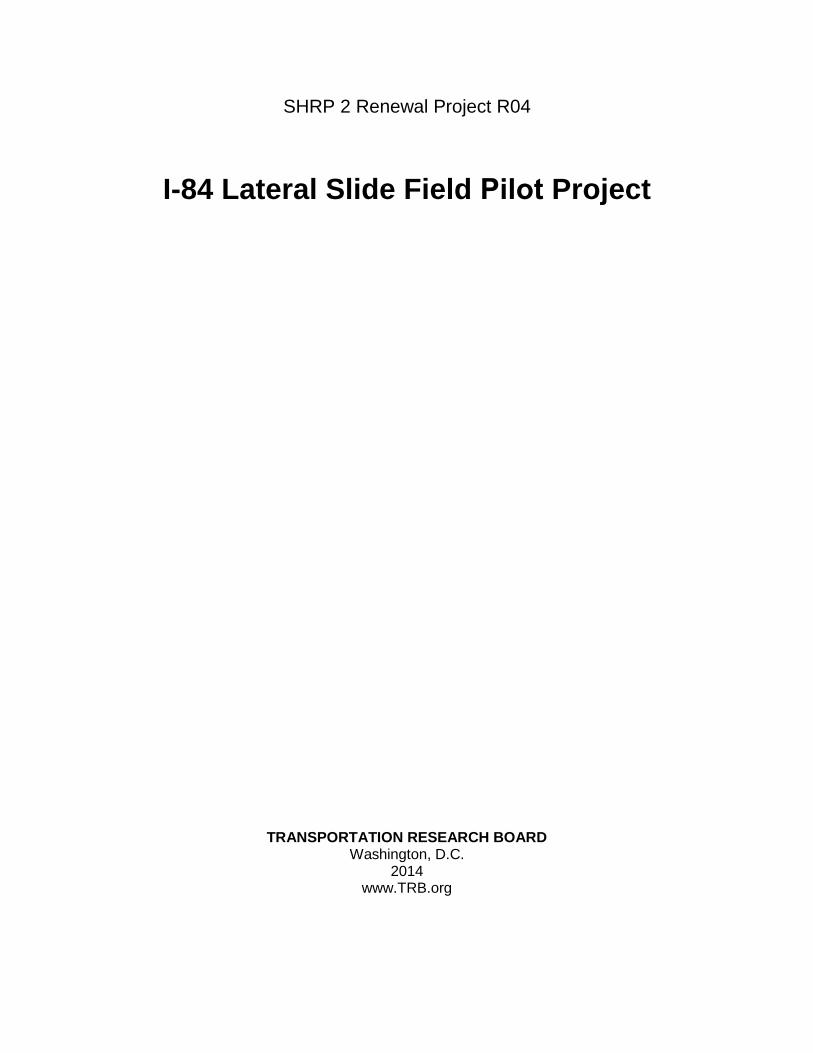
In 2011, as part of an ongoing research project, the Strategic Highway Research Program, SHRP 2 R04, of the Transportation Research Board identified the I-84 eastbound and westbound bridges over Dingle Ridge Road, owned by New York State Department of Transportation (NYSDOT), as an excellent candidate to demonstrate accelerated bridge construction methods for replacing an existing structure with the lateral slide method while making use of a precast concrete superstructure. This project was the second pilot project completed under SHRP 2 R04 and was selected from a number of potential projects received from several DOTs. The design was performed by the SHRP 2 R04 research team under Phase IV of the project, while HNTB provided construction-phase services under a separate contract with NYSDOT. This project was also awarded a $2 million grant by the Federal Highway Administration’s (FHWA) Highways for LIFE program for its innovative approach. Figure 1 shows the original bridges on the project site.
The original structures each carried two travel lanes over Dingle Ridge Road, spanning 135 ft with a three-span steel girder superstructure (Figure 1). The replacement structures each carry three travel lanes. Given limited vertical clearance over Dingle Ridge Road, the structures use an 80-ft precast concrete single-span NEXT beam superstructure. The abutments are semi-integral with elevated cap beams supported on drilled shaft foundations. The width of each new structure is 57 ft to accommodate three 12-ft travel lanes for traffic, with 6-ft (left) and 12-ft (right) shoulders and a TL-5 concrete barrier on each side.
Figure 1. Original I-84 Bridges over Dingle Ridge Road.
The twin structures carrying I-84 in Putnam County, New York—between Danbury, Connecticut, and I-684—are heavily traveled, with a peak average daily traffic (ADT) of up to 100,000, containing 16% truck traffic and a projected 30-year annual ADT of 117,281. Conventional bridge replacement would have extended over multiple years and required a temporary bridge in the median (estimated to cost approximately $2 million), as the original bridges were too narrow for cross-overs. Additionally, the elevation difference between the eastbound and westbound roadways made cross-overs more difficult. Use of ABC methods eliminated the need for a temporary bridge and allowed for the replacement of each structure during a single night closure. Maintaining traffic on the original bridges during fabrication and assembly of the new bridges off alignment minimized traffic disruption and the costs of work zone traffic control, improved safety, and minimized environmental impacts.
3. Pilot Project Innovative Features
Each new structure uses a no-skew, 80-ft single-span NEXT beam superstructure. The width of the new structure is 57 ft to accommodate three 12-ft travel lanes for traffic, with 6-ft (left) and 12-ft (right)

shoulders and a TL-5 concrete barrier on each side. One of the main goals of this SHRP 2 pilot project was to showcase a concrete superstructure system for ABC and the application of the SHRP 2 ABC Toolkit. The Dingle Ridge Road underpass is on a 15.6% grade, and the significant widening of the bridge created design challenges in maintaining the minimum underclearance requirements. NEXT beams were chosen for the superstructure to minimize structure depth because of the critical underclearance issues and to expedite design and construction while maintaining cost efficiency to meet ABC goals. Precast approach slabs were placed at each approach. All field connections in the superstructure and approaches used ultra-high-performance concrete (UHPC) closure pours. And all details for the NEXT beam superstructure, precast approach slabs, and closure pours were developed according to the standard ABC concepts in the toolkit.
A cast-in-place concrete straddle-bent abutment with 6-ft-diameter drilled shafts supports the new superstructure. Using a straddle-bent abutment allowed the drilled shafts to be installed outside the plan limits of the existing bridge, as underclearance for drilling rigs was limited. Columns, in-fill retaining walls, and cap beams were then formed and placed under the existing bridge with limited excavation and without disruption to traffic.
The contract was awarded at the end of December 2012, construction of the twin I-84 bridges over Dingle Ridge Road began in March 2013, and the first slide-in occurred Saturday, September 21, 2013. Notably, the first slide was completed only 9 months after contract award. Use of precast elements minimized the duration of field construction activities, allowing for the construction of these two bridges off alignment in just a few months. Implementation of ABC methods allowed for the replacement of each bridge during one weekend night closure, minimizing the impact on traffic. The lateral slide method eliminated the need for a temporary bridge located between the structures that would have been required to maintain traffic using conventional construction methods. The state realized significant cost savings by eliminating the need for a temporary bridge and associated roadwork. Thus the project successfully illustrated that ABC minimizes traffic disruption and the costs of work zone traffic control, improves safety, and minimizes environmental impacts.
4. Pilot Project Construction
4.1. Prebid Meeting
A prebid meeting was conducted on July 11, 2012, at the NYSDOT Region 8 offices in Poughkeepsie. In attendance were a wide range of primarily New York–based contractors interested in learning more about the project before submitting a construction bid. Contractors present included A. Servidone/B. Anthony, Northeast Prestressed, Lane Construction, ECCO, HVB Construction, Harrison & Burrowes Bridge Constructors, Mabey Bridge, and Halmar International. Representatives from NYSDOT and the SHRP 2 R04 design team were present to make detailed presentations on the innovative design aspects of the bridge and to answer questions from potential bidders. Contractors were given an overview of the project, including a description of the basic scope of work, indications of contractual requirements on the bridge closure, and an outline of the anticipated construction schedule.
The prebid meeting was organized to generate interest among potential bidders and answer any questions and concerns the contractors may have had regarding this new approach to bridge replacement. The goal was to avoid inflated bids that might arise from contractors’ perception of risks. The design team also shared sample plans for the rapid bridge demolition, temporary shoring for the superstructure, and the lateral slide system.
Given the large weekday traffic volumes of 40,000 vehicles per day on I-84, replacement of each bridge would occur during an approximately 16-hour directional weekend shutdown of I-84. An incentive/disincentive clause added to the contract would award or penalize the contractor $10,000 per

hour for early or late completion, respectively, to ensure I-84 would be open to two-way traffic by the following business day.
The directional shutdown of I-84 would be circumvented via a 3-mi detour on Route 6, which runs parallel to I-84, and would extend into Connecticut; Dingle Ridge Road would likely be closed to traffic for approximately 5 days for each slide. Contractors were informed that NYSDOT and Connecticut DOT would be responsible for public outreach concerning the closure periods and associated detours.
Contractors were reminded that they would be responsible for engineering design of the falsework to support the new superstructure and approach slabs and of the horizontal slide system. Additionally, contractors were reminded that they would need to submit qualifications for slide subcontractors if awarded the contract.
The following project milestones were presented to contractors:
• August 2, 2012 Plans, specifications, and estimates (PS&E).
• September 12, 2012 Project advertisement.
• October 11, 2012 Letting.
• December, 2012 Anticipated award.
• March to September 2013 Prepare site, construct new substructure elements, erect superstructures and approach slabs on falsework, and setup detours.
• September 2013 Perform lateral slides on two weekends in September; raise approach roadway approximately 2 ft to proposed profile during closure period.
At the time of the prebid meeting, the team assumed that the final 2-in. asphalt overlay with waterproofing membrane would be placed after the completion of the slide and outside the ABC closure window.
At the prebid meeting, significant attention was paid to the project schedule that would be followed by the successful bidder. Essentially, the contract was separated into three phases, specifying certain work that could be performed before the existing bridge was closed or after the new bridge was in place and, more important, the work tasks that could only be performed during the 16-hour ABC period.
Construction activities were divided into three phases—pre-ABC, ABC, and post-ABC—and scheduled in such a way as to minimize the work efforts required during the ABC closure period. Pre-ABC construction activities included casting the precast elements at the precast facility, erecting the falsework to support the new superstructure and approach slabs off alignment, erecting the superstructure and approach slabs on the falsework, constructing the abutments and wingwalls to the slide elevation, and widening the approach to three lanes to meet the original roadway profile. ABC construction activities included demolishing the existing superstructure, piers, and abutments; setting the sleeper slabs; placing bearings and slide pads on the abutments and sleeper slabs; horizontally sliding the superstructure and approach slabs onto the new abutments and sleeper slabs; placing joints; raising two lanes of the approach roadway to the final profile; and applying an overlay across the full length of the structure. Post-ABC activities included backfilling the abutment with flowable fill, raising the future third lane and shoulders of the approach roadway to the proposed profile, setting guiderail, capping the wingwalls, and casting the

abutment cheekwalls.
In an effort to minimize the closure period, the contractor removed as many tasks from the ABC window as possible. For example, the contractor placed the waterproofing membranes and tack coat for the final overlay on deck and approach slabs before performing the horizontal slide. The contractor made adjustments to the schedule of activities before performing the second slide to further streamline the ABC period. For example, the contractor elected to place a temporary barrier and demolish the railing on the original structure before the ABC window, eliminating the activity from the closure period.
Careful scheduling of activities in the three phases of construction helped minimize the closure period and disruption to the public.
4.2. Contractor Bids
The construction letting for the project was held on November 8, 2012. A total of 10 fully responsive bids were received, with a low bid of $10.2 million submitted by Yonkers Contracting Co., Inc. of Yonkers, New York. A summary of submitted bids follows:
• $10,243,480.15—Yonkers Contracting Co. Inc.; • $11,605,627.20—The Lane Construction Corp.; • $11,766,850.00—ECCO III Enterprises, Inc.; • $11,986,512.00—Halmar International, LLC; • $12,634,633.00—Lancaster Development, Inc.; • $12,798,971.20—DeFoe Corporation; • $12,853,853.85—Harrison & Burrowes Bridge Constructors; • $13,249,000.00—HVB & TWI Construction, JV; • $14,705,837.20—Grace Industries, LLC; and • $15,423,926.30—A. Servidone Inc./B. Anthony Construction Corp., JV.
These bids included several items, such as approach roadway work, that were not actually part of the ABC project itself. The low bid was within 3% of the engineer’s estimate of $10.536 million.
4.3. Preconstruction Meeting
The letting date, originally scheduled for October 11, was postponed to November 8, 2012, and the contract was awarded to Yonkers on December 26, 2012. The preconstruction meeting was held on January 17, 2013, at which time NYSDOT reviewed various contractual requirements with the contractor. The contractor provided a draft schedule of all construction activities showing work being completed at the end of December 2013, consistent with NYSDOT’s project completion date.
4.4. Site Preparation
Yonkers commenced work on February 7, 2013. Site preparation included clearing of a few small trees and grubbing the work areas, building of construction entrances, and installation of erosion and settlement controls and other environmental devices. (See Figure 2.)

Figure 2. Site Access Preparations.
Considerable earthwork was included in the scope of the project. Widening of the existing approach roadways from two lanes to three lanes was primarily achieved by extending the roadway into the median area. Given the elevation difference between the eastbound and westbound roadways, considerable earthwork was required to achieve the desired profiles. The contractor also created access and work areas in the median and around the existing structures with temporary embankments.
In creating construction access on the existing slopes between the piers and stub abutments of the original structures, the contractor had to be mindful not to make the original abutments unstable, as they were founded on shallow foundations built into the slopes. Over-excavation of the existing slopes could have resulted in a global stability failure of the structure abutments.
4.5. Precast Element Fabrication
The superstructure and approach slabs of the bridges consist of precast concrete elements, which shortened the overall duration of field construction activities. Precast elements include end diaphragms with slide shoes, NEXT beams, approach slabs, and sleeper slabs. All precast elements were fabricated by Dailey Precast in Shaftsbury, Vermont. The details were developed using the SHRP 2 ABC Toolkit.
4.5.1. NEXT Beams
Each new superstructure consists of six 36-in.-deep Type D NEXT beams spanning 79 ft, 4 in. and having a full thickness flange intended to serve as the riding surface at the conclusion of the ABC period. (See Figure 3.)
The fabricator measured actual beam camber at transfer, at release, 3 days after release, 1 week after release, and every week thereafter until the beams left the yard. Initial measurements after release indicated larger camber than initially expected and caused concern that the cambers would be out of tolerance at delivery. Initially, camber was measured with the beams supported approximately 5 ft from the actual final bearing locations. This decrease in the beam span decreased the downward deflections of the beams because of self-weight that would have countered the upward deflections from prestress. While changing the support location decreased the apparent camber, net camber growth values were still high because of time-dependent camber effects caused by the decreased beam span length. The fabricator preloaded the beams to minimize further camber growth, and camber at shipping remained within contractual tolerances.

Figure 3. NEXT Beam in Fabrication Yard (Photo Courtesy of NYSDOT).
The exterior NEXT beams were cast integral with the standard NYSDOT curb/shear key detail for use with single-slope concrete barriers. Before casting of the exterior beams, the curb detail was increased in height to accommodate beam camber. The beams were cast in pairs, and during curing of the initial two exterior NEXT beams, fine cracks formed in these barrier keys. The cracks were most likely a result of the monolithic curb base being in place at release of prestress, as there was no longitudinal reinforcement within the key detail. Although these cracks were expected to close under the weight of superimposed dead loads, such as barrier self-weight, the fabricator sealed the cracks before shipping the beams to the site. In the two exterior beams that had not yet been cast when this cracking was observed, the fabricator placed two additional longitudinal bars (#5) in the barrier shear key to help prevent similar cracking.
4.5.2. End Diaphragms
The precast end diaphragm serves as a bridge between the slide elevation (which had to remain below the original structure) and the NEXT beam bearing elevation required to maintain adequate minimum overhead clearance over Dingle Ridge Road and to reach the desired final profile. It also transfers the loads from the NEXT beam bearings to the slide shoes. Each precast end diaphragm is 4-ft wide and was cast monolithically with four slide shoes (Figure 4). The end slide shoe on the north end of each end diaphragm is flush with the outside face of the end diaphragm and creates the bearing surface for the push block used to push or pull the superstructure during the lateral slide. The precast end diaphragms vary in height to follow the roadway cross slope.

Figure 4. End Diaphragm Fabrication (Photo Courtesy of NYSDOT).
The NEXT beams sit on reinforced elastomeric pads that bear directly on the end diaphragms. Without a grout bed, there is no room for geometric adjustments of the NEXT beams on the end diaphragms to help achieve the appropriate final profile. The end diaphragms had not been cast when the NEXT beams were found to potentially have more camber than anticipated. To provide the geometric adjustability required for the NEXT beams to meet the desired profile, the diaphragm depth was decreased by 2 in. before fabrication.
While curing, cracks were identified in the end diaphragms. The cause of the cracks is unknown, but possible factors may include some or a combination of the following: early removal from forms and placement on temporary supports before the concrete achieved adequate strength, reduced moment capacity resulting from the 2-in. reduction in section depth, and/or the location of the temporary supports. All cracks were sealed by epoxy injection at the fabrication facility.
4.5.3. Approach Slabs
The precast approach slabs span 33 ft, 1 in. from the end diaphragms to the sleeper slabs. The approach slabs have been designed for both dead load and live load, as they act as jump spans in the interim between the end of the ABC period and completion of placement of the controlled low-strength material fill behind the abutments.
The contractor intended to slide the superstructure and approach slabs in place by pushing at the abutment end diaphragm location alone. Each approach slab was doweled into the end diaphragm. Although a final end diaphragm pour tied the approach slabs to the end diaphragm and NEXT beams, the contractor elected to add additional dowels and reinforcement in the panels to carry the horizontal friction loads of the approach slab on the sleeper slab. The additional reinforcement served as added safety during the horizontal slide.
At the sleeper slab locations, the ends of the approach slabs were down-turned 90o to meet the slide elevation. The surface had to be double beveled to account for the profile grade and cross slope of the roadway. Stainless steel plates were cast into the ends to ride over the PTFE sheets used during the slide.
4.5.4. Sleeper Slabs
The precast sleeper slabs are inverted tee sections, with the stem acting as the end dam for the approach roadway raising. The top of the stem was intended to serve as the riding surface before placement of the

final asphalt course. The top of footing of the sleeper slab served as the sliding surface for the approach slab. The sleeper slabs were precast in three segments to allow installation of one of the exterior segments before the ABC period.
The top of the sleeper slab stem follows the roadway cross slope. The crown of the roadway is not centered on the structure, so the sleeper slab is not symmetrical about the centerline of the bridge. Two of the sleeper slabs were incorrectly detailed and fabricated, as the cross slope was not mirrored correctly. This error in fabrication was not noticed until the precast segments were brought into the field. The contractor chose to sawcut the stem of the improperly fabricated sleeper slab segments to obtain the correct cross slope. This was done during the pre-ABC period without any schedule impact.
4.6. Abutment Construction to Slide Elevation
Work on the new bridges commenced while the original bridges remained in service. Abutment drilled shaft foundations, columns, and cap beams were constructed up to the slide elevation under the existing structure using cast-in-place construction. A breast wall beneath the cap beam was cast concurrently with the columns to serve as a curtain wall, retaining soil behind the abutment. Precast modular T-Walls, serving as wingwalls, were installed to an elevation just below the slide surface. The abutments were backfilled and compacted with select structural fill up to the sliding surface.
4.6.1. Drilled Shafts
Abutment foundation selection was limited by construction sequencing, as it was necessary to construct the new substructures while the existing bridges were still in place. Foundation construction beneath the existing bridge would require low overhead clearance methods, and pile driving vibrations or excavation for pile caps could potentially destabilize the existing shallow foundations at the piers and stub abutments. Excavation support options were limited and costly as most typical excavation support systems require overhead clearance for installation. Options were further reduced by a low settlement tolerance necessary to maintain vertical alignment during the bridge slide. For these reasons, rock-socketed drilled shaft foundations were selected as the most practical foundation type, to be installed on either side of the existing structures outside the existing bridge footprints. Each 6-ft-diameter shaft was designed to directly carry one of the two columns, as well as the earth pressure load on the curtain wall and cap beam connecting the columns.
Figure 5. Drilled Shaft Soil Auger.
Drilled shaft drilling operations commenced at the beginning of April. Shaft excavation was conducted by Cook Drilling Corporation of Trevose, Pennsylvania, using two self-erecting rotary drill rigs working
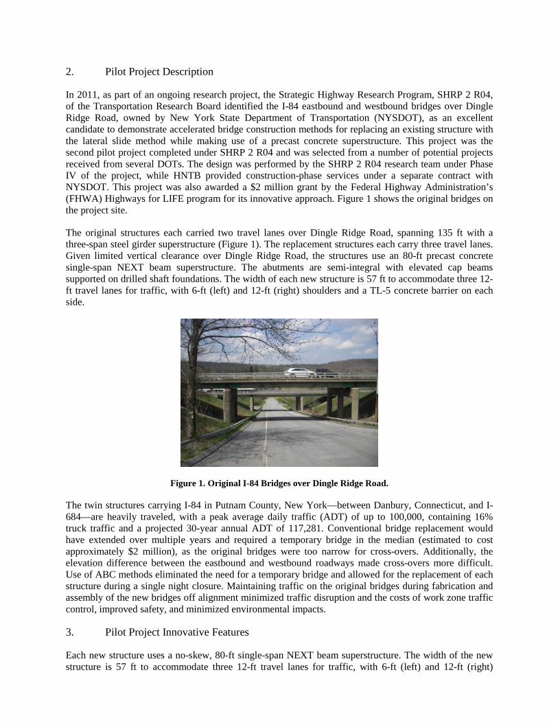
concurrently with soil and rock augers and core barrels. (See Figures 5 and 6.) The upper 10 ft of excavation was typically stabilized using an oversized casing, after which a full-length 6-ft-diameter interim casing to remain in place was installed to a minimum of 6 in. below the top of rock to minimize soil intrusion. Rock sockets were excavated, the annulus between outer and interim casing was backfilled with flowable fill, and the outer casing was removed. Following satisfactory inspection, reinforcing cages were placed and concrete was poured.
Figure 6. Drilled Shaft Core Barrel.
Crosshole sonic logging (CSL) was specified at all drilled shafts to verify concrete integrity; however, the design required column reinforcement to extend into the shafts. The column reinforcement would obstruct access to the top of the shafts, preventing coring or grouting in the event that a defect was encountered during CSL testing. To minimize the obstruction, the cold joint at the base of the column/top of the shaft was moved further down the shaft beyond the required column reinforcement embedment depth. This allowed for completion of CSL testing before placement of column reinforcement and maintained the option to core or remediate drilled shaft concrete if required. The remaining drilled shaft concrete was later poured in conjunction with the column above.
All drilled shaft work installation and CSL testing was completed by the middle of May, allowing construction to move forward with the columns and curtain wall.
4.6.2. Columns, Walls, and Cap Beams
Forming and rebar installation for the abutment columns and curtain wall commenced at the beginning of May. The contract plans called for the columns and curtain wall to be cast separately, with the columns calling for a higher strength concrete than the curtain walls. The contractor requested permission to cast the walls and columns concurrently. Permission was granted for the contractor to pour the walls and columns as one pour using the higher strength concrete and providing relief joints between the columns and curtain wall between the columns.
With the columns and curtain walls in place, the contractor commenced backfilling operations while starting to form and place rebar for the cap beams. The contractor brought the fill to the elevation of the bottom of the cap beam, leaving no room for bottom formwork. The contractor used the fill as the bottom formwork for the abutment cap beam. Work on the cap beams was performed in tight quarters, as the top of the cap beam was just below the bottom of the steel of the original structure. Placing and vibrating the concrete proved to be difficult given the limited overhead clearance available.
Abutment work was completed by the end of August to allow adequate cure time for the anticipated

September slide dates. However, the limited vertical clearance available for the cap beam construction was further complicated by poor timing of concrete delivery (long gaps between ready mix deliveries) at the eastbound east abutment and inadequate pumpability of the concrete mix per specifications. When the forms were removed from the cap beam, several cold joints were identified (see Figure 7), along with large areas of voids and poorly consolidated concrete, ultimately leading to the rejection of the cap beam. The original plans called for the eastbound structure to be the first of the two structures slid into place. Reconstruction of the cap beam delayed the slide for the eastbound structure, and a decision was made to slide the westbound structure into place first.
Figure 7. Eastbound East Abutment.
Given the difficulties with the concrete mix at the eastbound east end, modifications to the mix were permitted, allowing the contractor to use a mix that provided the same concrete strength with increased flowability for pumping. In the reconstruction of the eastbound east abutment cap beam, details were revised to help obtain a more durable product. A bottom form was used to ensure adequate and even bottom cover. Bottom cover was increased from 2 in. to 3 in. The main reinforcement was revised to be a single bar rather than being spliced at the columns. This rebar modification helped alleviate congestion and facilitated concrete placement and access for proper vibration. The cap beam was demolished and reconstructed within the month of September.
4.6.3. T-Walls
The T-Wall modular precast concrete wall system was selected as the system of choice given the pace of the project, stepped embankment slopes, limited overhead access, and staged construction requirements. This system consists of stacked precast concrete face units with concrete stems located centrally behind each unit, extending back into the soil mass. Friction between the stems and the surrounding fill material—as well as shear blocks between the vertically stacked stems—cause the combined T-Wall and surrounding soil mass to act as a gravity wall. Modular units were precast off-site well in advance; once on site, installation was quick and simple.
Grading for the wingwalls commenced at the end of May, and setting of T-Wall units began in mid-June, following completion of the adjacent columns and curtain walls. The T-Walls were placed concurrently with the abutment fill behind the curtain walls, beneath the existing structures, until the slide elevation was reached and overhead clearance became limited. The T-Walls were installed to the slide elevation by the middle of August.
The remaining modular units for the uppermost wall course were installed following the ABC period to avoid conflicts with the new structures during the slide. At that point, conventional backfilling and

compaction were obstructed by the new structure; so the T-Walls and abutments were backfilled to the bottom of the approach slab using flowable fill, pumped in from the sides of the new structure and through grout ports near the crest of the new deck. Pumping of flowable fill proved difficult using the standard NYSDOT mix design, so the cement content of the mix was increased to improve pumpability.
The new wingwalls span from the abutment columns to the sleeper slabs (Figure 8). Because the sleeper slabs prevent placement of a T-Wall unit, a gap existed between the sleeper slab stem at the end of each approach slab and the nearest T-Wall unit. To close this gap, a precast panel was installed at each end of each sleeper slab. Inserts were cast into the sleeper slab ends to allow the panels to be bolted into place during the post-ABC period.
Figure 8. T-Wall wingwall. 4.7. Asbestos Abatement
The original structures had asbestos sheeting between the abutment backwall and the deck. The R04 team identified this issue during the design phase. Asbestos abatement work must be performed within enclosures to properly contain asbestos during removal operations. No other work is permitted within the enclosure or the surrounding area. Given these constraints, asbestos abatement would not have been possible during the ABC closure period. Instead, abatement was performed as night work before the slide. The contractor removed segments of deck over the abutment backwalls, performed the asbestos abatement, and dropped precast concrete blocks on temporary cribbing during various overnight closures.
4.8. Temporary Falsework and Temporary Crane Platforms
To perform a lateral slide, the new superstructure and approach slabs needed to be constructed off alignment (alongside the existing bridges) and at the same elevation as their final location on the new substructure elements. The steep grade along Dingle Ridge Road made necessary substantial temporary falsework to the north of each structure. Siefert Associates, the contractor’s engineer, designed the temporary falsework. Braced double-column primary bents were constructed in line with the new abutments (Figure 9). Header beams supported slide tracks, which were used to support the end diaphragms. Secondary bents with a single-column line were constructed adjacent to the new sleeper slab locations. These bents were also capped with a slide track, on which the approach slabs were supported. Overall field construction durations were decreased by constructing the superstructure and approach slabs on the temporary falsework concurrently with substructure construction.

Figure 9. Primary bent. Source: NYSDOT.
Pile driving equipment was mobilized and work on the temporary falsework commenced at the end of May. The temporary supports for the new superstructures were completed and ready for the delivery of the precast elements by the end of July.
Given the steep grade along Dingle Ridge Road, crane platforms were required at either end of the new structure being constructed off alignment. The cranes were used to pick and place the precast concrete elements that were delivered during nighttime lane closures on I-84. The contractor made use of crane mats on built-up embankment in the median area to support the cranes picking the precast elements for the new eastbound structure. For the westbound structure, the contractor constructed temporary crane platforms to the north of the westbound roadway, where the erection cranes were located. The platforms were completed by the middle of July and cranes were mobilized soon thereafter, ready for the delivery of the precast elements.
4.9. Superstructure and Approach Slab Erection
4.9.1. End Diaphragm, NEXT Beams, and Approach Slabs
Once the falsework was erected, delivery and setting of the precast concrete superstructure elements commenced. New superstructure erection occurred concurrently with the construction of the new substructure elements.
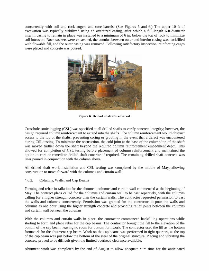
The precast diaphragms and NEXT beams for the westbound structure were delivered overnight on July 18–19 (Figure 10). When the end diaphragms were lifted over the slide track, the contractor realized that the slide shoes would not fit within the slide track. The concrete faces of the slide shoes were ground down to allow the end diaphragms to sit within the slide track on the falsework. Once the end diaphragms were placed appropriately, the contractor set out reinforced elastomeric bearings for the NEXT beams. The NEXT beams were placed with dual crane picks because of their weight and length. Both end diaphragms and the six NEXT beams were erected overnight for each structure.
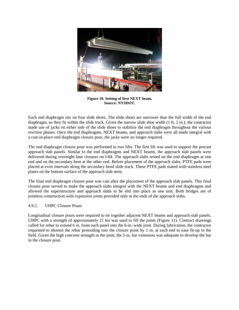
Figure 10. Setting of first NEXT beam. Source: NYSDOT.
Each end diaphragm sits on four slide shoes. The slide shoes are narrower than the full width of the end diaphragm, so they fit within the slide track. Given the narrow slide shoe width (1 ft, 2 in.), the contractor made use of jacks on either side of the slide shoes to stabilize the end diaphragm throughout the various erection phases. Once the end diaphragms, NEXT beams, and approach slabs were all made integral with a cast-in-place end diaphragm closure pour, the jacks were no longer required.
The end diaphragm closure pour was performed in two lifts. The first lift was used to support the precast approach slab panels. Similar to the end diaphragms and NEXT beams, the approach slab panels were delivered during overnight lane closures on I-84. The approach slabs rested on the end diaphragm at one end and on the secondary bent at the other end. Before placement of the approach slabs, PTFE pads were placed at even intervals along the secondary bend slide track. These PTFE pads mated with stainless steel plates on the bottom surface of the approach slab stem.
The final end diaphragm closure pour was cast after the placement of the approach slab panels. This final closure pour served to make the approach slabs integral with the NEXT beams and end diaphragms and allowed the superstructure and approach slabs to be slid into place as one unit. Both bridges are of jointless construction with expansion joints provided only at the ends of the approach slabs.
4.9.2. UHPC Closure Pours
Longitudinal closure pours were required to tie together adjacent NEXT beams and approach slab panels. UHPC with a strength of approximately 21 ksi was used to fill the joints (Figure 11). Contract drawings called for rebar to extend 6 in. from each panel into the 6-in.-wide joint. During fabrication, the contractor requested to shorten the rebar protruding into the closure point by 1 in. at each end to ease fit-up in the field. Given the high concrete strength in the joint, the 5-in. bar extension was adequate to develop the bar in the closure pour.

Figure 11. Placing of UHPC.
A Buy-America waiver was accepted for use of the steel fibers in the UHPC for this project. Representatives from Lafarge, the supplier, mixed their product, Ductal, on site in a pair of mixers for each structure and transported the UHPC to the joints using buggies. UHPC is very fluid and self-leveling in nature and required all formwork to be watertight to prevent leakage of the material. All formwork was tested before closure pour placement. The contractor used strips of 1/4-in. plywood on each side of the joint and top forms to allow a slight overfilling. The UHPC was placed in the joints, working from the low end to the high end of each structure, and was allowed to flow around the reinforcing steel and completely fill the joint.
4.9.3. Concrete Barriers, Waterproofing, Tack Coat Application, and Sleeper Slabs
The concrete barriers were slip formed along both fascia of each structure after the completion of the longitudinal closure pours. These barriers were made integral with the deck using reinforcement bars that protruded from the deck into the barrier.
Just before the first slide, the deck surfaces were sprayed with a three-coat waterproofing system. After the slide of the westbound bridge, the contractor chose to eliminate an additional task from the ABC window and placed the tack coat for the asphalt overlay on top of the waterproofing membrane before the slide.
The sleeper slabs were fabricated in three segments to allow for the installation of a portion of the sleeper slab before the lateral slide. The leading sleeper slab segment was installed before the trial slide, as the structure had to slide a minimum of 5 ft onto the new abutments and sleeper slabs.
4.10. Trial Slide
Within the last 10 days before each ABC period, the contractor performed a trial slide to ensure the proper functionality of the slide systems. Contractually, the contractor was required to move each structure a minimum of 15 ft and a minimum of 5 ft onto the new substructure and return the structure to its original position.
The westbound bridge trial slide occurred on September 13, 2013. During the westbound trial slide, the stem of the west approach slab was uneven and sloped downward a bit at the end, pinching the Teflon pads and pushing them rather than sliding over them. Additionally, after the first slide shoe was completely off the primary bent, the bearings on the abutment compressed such that the bottom of the slide shoe was lower than the slide track; that meant the superstructure had to be jacked vertically to

retract it onto the slide tracks and back into its original position.
The eastbound bridge trial slide occurred on October 10, 2013. Because of the difficulties with wracking of the superstructure during the westbound bridge slide, the contractor took meticulous measurements of each movement of the structure during the trial slide for the eastbound structure. Although the process of measuring slowed the trial slide, the contractor was able to maintain proper alignment of the superstructure throughout the trial slide. In an effort to ensure that the slide shoes would ride over the Teflon pads, the pads were tapered along the leading edge. However, at each abutment, a slide shoe pushed one Teflon pad on the slide track rather than riding over it. Part way through the trial slide, the contractor jacked the superstructure at each abutment to add the missing Teflon pad. Finally, having successfully performed both the trial and actual slides for the westbound structure, the contractor asked to leave the eastbound superstructure partially on the substructure, rather than retracting it to its original position. This modification allowed the contractor to save some time on the slide during the eastbound ABC period.
4.11. ABC Period
The first lateral slide occurred on September 21–22, 9 months after the award of the contract and less than 6 months after the start of on-site bridge construction activities. The second slide occurred 1 month later, on October 19–20.
Once the initial substructure work was completed and the superstructure was constructed, traffic was detoured to local State Route 6. NYSDOT and Connecticut DOT handled all traffic management during the ABC period. The original bridge was demolished, and the approach roadway was raised to the new profile. The bridge was dropped onto the closed roadway below and cleaned up by the next morning. The remaining two segments of precast sleeper slab were placed at the end of either approach to serve as an end dam for the raised approaches and also to serve as a sliding surface for the approach slabs. The superstructure and approach slabs were then slid in place on PTFE pads against stainless steel mating surfaces, which offer very low friction resistance. Hydraulic jacks were used to push the new superstructure and approach slabs onto the new abutments and sleeper slabs. A mix of permanent elastomeric bearings with PTFE and temporary slide bearings (steel blocks with PTFE) were used for the slide. With the structure in place, joints were placed, and an asphalt overlay was placed over the length of the structure. The approach slabs were designed as a jump slab to temporarily carry traffic after the slide-in and before the abutment backfill was completed, allowing traffic to be rerouted onto the new structure at this point.
4.12. ABC Time Frame and Schedule
The ABC time frame is considered to begin with the closure of the original crossing and to end when traffic is rerouted over the new bridge. Closure of the roadway crossing lasted 1 night (20 hours) to allow for the rapid demolition of the original bridge and slide-in of the new superstructure and approach slabs. The existing bridge was closed at 5 p.m. on Saturday and the new bridge was opened at 1 p.m. on Sunday. Figure 12 depicts the schedule during the ABC time frame for the replacement of each I-84 bridge over Dingle Ridge Road.

Figure 12. ABC closure period construction schedule.
4.12.1. Demolition of Existing Bridge
Demolition of each bridge was performed by several crews working simultaneously. A hoe ram located at each approach commenced the demolition of span two by punching through the deck over the piers until span two was free to fall onto the roadway below—which was closed to traffic and protected by a couple of feet of fill (Figure 13). Two shears working from Dingle Ridge road commenced the demolition of span two by first removing the bridge rails. Once the span was lowered to Dingle Ridge Road, the shears continued to work side by side until the span was completely demolished. Front end loaders hauled the concrete debris to a temporary spoils stockpile, while the shears collected the steel and reinforcement into a separate scrap metal stockpile.
Figure 13. Demolition of span two.
Demolition of spans one and three occurred simultaneously with the demolition of span two. An excavator and hoe ram located at each approach demolished spans one and three. The hoe ram was used to break up the railing and to punch through the deck (Figure 14). The excavator cleaned off debris, including all of the deck reinforcement. Once the deck was removed, ironworkers flame cut the diaphragms, and the excavators were used to lift out the stringers. Once the superstructure was removed, the hoe rams continued with concrete removal at the abutments to the appropriate removal limits for sleeper slab placement.

Figure 14. Demolition of approach span. With the superstructure removed from spans one and three and span two demolished, the shears began to break away the concrete at the base of the pier columns. Once the column sections were necked down, the shears worked together to rock the piers back and forth until failure (Figure 15). The shears continued to demolish the piers on the protected surface of Dingle Ridge Road.
Figure 12. Pier demolition.
4.12.2. Approach Roadway
Two lanes of the approach roadway were raised during the ABC closure period. The new profile is approximately 2 ft higher than the original profile, so extensive approach roadway work occurred concurrently with bridge demolition and lateral slide activities. Several crews worked together to place and roll asphalt binder courses, tack coats, and top course throughout the closure period.
4.12.3. Lateral Slide
With demolition of the existing structure complete, crews quickly removed debris from the areas around the new abutments. All shielding and blast mats protecting the new abutments were removed. The abutment cap beams were swept clean of smaller debris. Temporary slide bearings were set along the full length of the abutment cap beam at regular intervals (Figure 16).
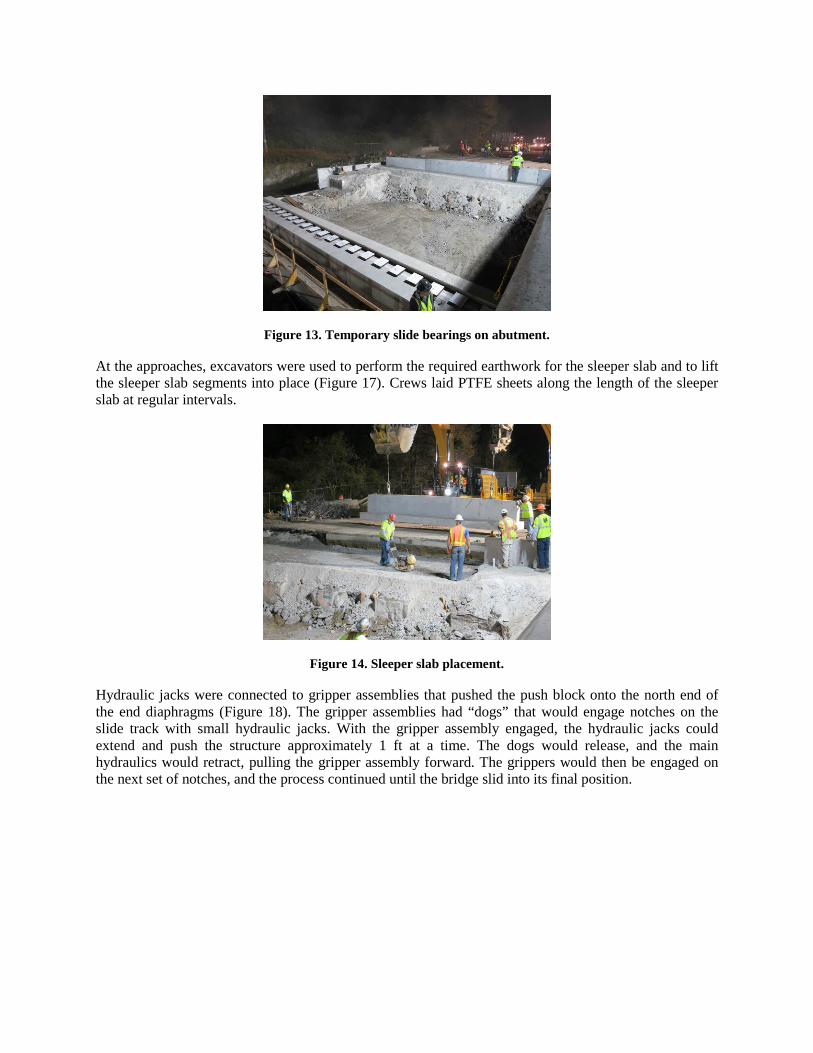
Figure 13. Temporary slide bearings on abutment. At the approaches, excavators were used to perform the required earthwork for the sleeper slab and to lift the sleeper slab segments into place (Figure 17). Crews laid PTFE sheets along the length of the sleeper slab at regular intervals.
Figure 14. Sleeper slab placement.
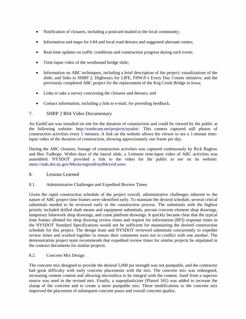
Hydraulic jacks were connected to gripper assemblies that pushed the push block onto the north end of the end diaphragms (Figure 18). The gripper assemblies had “dogs” that would engage notches on the slide track with small hydraulic jacks. With the gripper assembly engaged, the hydraulic jacks could extend and push the structure approximately 1 ft at a time. The dogs would release, and the main hydraulics would retract, pulling the gripper assembly forward. The grippers would then be engaged on the next set of notches, and the process continued until the bridge slid into its final position.
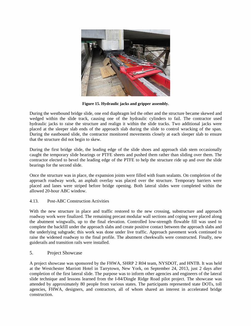
Figure 15. Hydraulic jacks and gripper assembly. During the westbound bridge slide, one end diaphragm led the other and the structure became skewed and wedged within the slide track, causing one of the hydraulic cylinders to fail. The contractor used hydraulic jacks to raise the structure and realign it within the slide tracks. Two additional jacks were placed at the sleeper slab ends of the approach slab during the slide to control wracking of the span. During the eastbound slide, the contractor monitored movements closely at each sleeper slab to ensure that the structure did not begin to skew.
During the first bridge slide, the leading edge of the slide shoes and approach slab stem occasionally caught the temporary slide bearings or PTFE sheets and pushed them rather than sliding over them. The contractor elected to bevel the leading edge of the PTFE to help the structure ride up and over the slide bearings for the second slide.
Once the structure was in place, the expansion joints were filled with foam sealants. On completion of the approach roadway work, an asphalt overlay was placed over the structure. Temporary barriers were placed and lanes were striped before bridge opening. Both lateral slides were completed within the allowed 20-hour ABC window.
4.13. Post-ABC Construction Activities
With the new structure in place and traffic restored to the new crossing, substructure and approach roadway work were finalized. The remaining precast modular wall sections and coping were placed along the abutment wingwalls, up to the final elevation. Controlled low-strength flowable fill was used to complete the backfill under the approach slabs and create positive contact between the approach slabs and the underlying subgrade; this work was done under live traffic. Approach pavement work continued to raise the widened roadway to the final profile. The abutment cheekwalls were constructed. Finally, new guiderails and transition rails were installed.
5. Project Showcase
A project showcase was sponsored by the FHWA, SHRP 2 R04 team, NYSDOT, and HNTB. It was held at the Westchester Marriott Hotel in Tarrytown, New York, on September 24, 2013, just 2 days after completion of the first lateral slide. The purpose was to inform other agencies and engineers of the lateral slide technique and lessons learned from the I-84/Dingle Ridge Road pilot project. The showcase was attended by approximately 80 people from various states. The participants represented state DOTs, toll agencies, FHWA, designers, and contractors, all of whom shared an interest in accelerated bridge construction.

The showcase agenda included detailed presentations of design and construction of I-84 over Dingle Ridge Road from various perspectives on the project: owner, designer, and contractor (Figure 19). Following lunch at the conference hotel, the showcase attendees were encouraged to visit the project site (Figure 20). Bus transportation was provided to the project site, and attendees were allowed to freely observe all aspects of the construction progress. Five NYSDOT representatives familiar with the project were available to help answer any questions about the design or construction.
Figure 16. Showcase presentation. Source: Rick Raglow.
Figure 17. Showcase site visit. Source: Rick Raglow.
After the site visit, attendees returned to the hotel conference room for final presentations, a discussion, and an opportunity for questions and comments on lessons learned throughout the construction phases of the project.
In the weeks following the showcase, the speaker presentations were made available in PDF format to all participants. These showcase presentations are downloadable from the Highways for LIFE website.
6. Public Outreach
NYSDOT focused great efforts on reaching out to the project stakeholders, trucking community, and general public to keep everyone informed on the project and the timing and duration of closures associated with the project. Outreach like this is an opportunity to educate and inform the public about new construction techniques and to build and foster relationships that allow an agency to establish

credibility and trust with the affected community. These outreach efforts helped minimize public resistance to the project and build support for the ABC replacement approach.
NYSDOT reached out to stakeholders in various ways, including holding meetings with stakeholders, launching a project website, providing Twitter and Facebook updates, providing statements to the media and press, sending postcards to local residents and companies (see Figure 21), setting up displays, and setting variable message sign (VMS) displays to reach commuter traffic. Efforts to connect with the public and trucking communities reduced traffic delays on the detours and surrounding roads by reducing traffic volumes, especially truck traffic, before and during the events. During the peak hours, traffic dropped nearly 50%, from approximately 3,000 to 1,500 vehicles per hour; this reduction allowed the one-lane detour to handle the interstate traffic. Raising public awareness of the project also helped minimize work zone–related accidents. The significant reduction in total peak hour traffic volumes on the I-84 corridor during the ABC closures can be attributed to the effective public outreach and communication efforts implemented by NYSDOT and partner agencies.
The public had several opportunities to provide feedback to NYSDOT. The public responded to web surveys, wrote e-mails to the regional office, provided statements in various local media reports, and spread comments via word of mouth. The various methods of communication allowed NYSDOT to work with the local community and respond to the needs of the people to help improve the community’s satisfaction with and understanding of the project.
Figure 21. Postcard alerting public to closure period.
6.1. NYSDOT Project Website
NYSDOT launched a project website which was revised throughout construction: www.dot.ny.gov/NYI84CT. Information provided on the website included the following:
• Notification of closures, including a postcard mailed to the local community;
• Information and maps for I-84 and local road detours and suggested alternate routes;
• Real-time updates on traffic conditions and construction progress during each event;
• Time-lapse video of the westbound bridge slide;
• Information on ABC techniques, including a brief description of the project; visualizations of the slide; and links to SHRP 2, Highways for LIFE, FHWA’s Every Day Counts initiative, and the previously completed ABC project for the replacement of the Keg Creek Bridge in Iowa;
• Links to take a survey concerning the closures and detours; and
• Contact information, including a link to e-mail, for providing feedback.
7. SHRP 2 R04 Video Documentary
An EarthCam was installed on site for the duration of construction and could be viewed by the public at the following website: http://earthcam.net/projects/nysdot/. This camera captured still photos of construction activities every 5 minutes. A link on the website allows the viewer to see a 1-minute time-lapse video of the duration of construction, showing approximately one frame per day.
During the ABC closures, footage of construction activities was captured continuously by Rick Raglow and Ben Tudhope. Within days of the lateral slide, a 3-minute time-lapse video of ABC activities was assembled. NYSDOT provided a link to the video for the public to see on its website: mms://mds.dot.ny.gov/Mexis/region8/nyi84ctvid.wmv.
8. Lessons Learned
8.1. Administrative Challenges and Expedited Review Times
Given the rapid construction schedule of the project overall, administrative challenges inherent to the nature of ABC project time frames were identified early. To maintain the desired schedule, several critical submittals needed to be reviewed early in the construction process. The submittals with the highest priority included drilled shaft means and equipment submittals, precast concrete element shop drawings, temporary falsework shop drawings, and crane platform drawings. It quickly became clear that the typical time frames allotted for shop drawing review times and request for information (RFI) response times in the NYSDOT Standard Specifications would not be sufficient for maintaining the desired construction schedule for this project. The design team and NYSDOT reviewed submittals concurrently to expedite review times and worked together to ensure their comments were not in conflict with one another. The demonstration project team recommends that expedited review times for similar projects be stipulated in the contract documents for similar projects.
8.2. Concrete Mix Design
The concrete mix designed to provide the desired 5,000 psi strength was not pumpable, and the contractor had great difficulty with early concrete placements with the mix. The concrete mix was redesigned, increasing cement content and allowing microsilica to be integral with the cement. Sand from a superior source was used in the revised mix. Finally, a superplasticizer (Plastol 341) was added to increase the slump of the concrete and to create a more pumpable mix. These modifications to the concrete mix improved the placement of subsequent concrete pours and overall concrete quality.
8.3. PTFE Slide Bearings
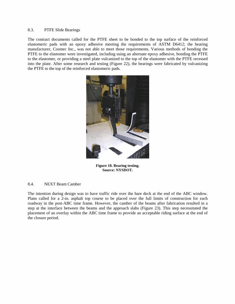
The contract documents called for the PTFE sheet to be bonded to the top surface of the reinforced elastomeric pads with an epoxy adhesive meeting the requirements of ASTM D6412; the bearing manufacturer, Cosmec Inc., was not able to meet those requirements. Various methods of bonding the PTFE to the elastomer were investigated, including using an alternate epoxy adhesive, bonding the PTFE to the elastomer, or providing a steel plate vulcanized to the top of the elastomer with the PTFE recessed into the plate. After some research and testing (Figure 22), the bearings were fabricated by vulcanizing the PTFE to the top of the reinforced elastomeric pads.
Figure 18. Bearing testing. Source: NYSDOT.
8.4. NEXT Beam Camber
The intention during design was to have traffic ride over the bare deck at the end of the ABC window. Plans called for a 2-in. asphalt top course to be placed over the full limits of construction for each roadway in the post-ABC time frame. However, the camber of the beams after fabrication resulted in a step at the interface between the beams and the approach slabs (Figure 23). This step necessitated the placement of an overlay within the ABC time frame to provide an acceptable riding surface at the end of the closure period.

Figure 19. Step resulting from NEXT beam camber.
Possible solutions include accounting for an asphalt overlay within the ABC window or providing a variable depth top flange on the NEXT beams to offset the effects of the camber and provide an acceptable riding surface at the completion of the ABC time frame. The variable depth top flange would be thicker at the ends by an amount equivalent to the anticipated camber and would decrease to the minimum required flange thickness at midspan.
Camber is an important element in ABC construction. Estimating camber in prestressed sections is difficult as camber is affected by many variables outside the designer’s control. According to the NYSDOT Bridge Manual, “The contract plans shall show the camber at prestress transfer and the deflections due to non-composite dead load and superimposed dead load.” Estimated camber at shipping is required on shop drawings but not on design drawings. The typical NYSDOT prestressed concrete beam construction is used in conjunction with a cast-in-place deck or an asphalt overlay. Beam haunches or overlays provide the necessary adjustability between the final beam camber and the desired final profile.
Anticipated final camber, camber at shipping, and camber at erection should be included on contract plans for precast elements which are intended to be used without the placement of a cast-in-place deck or overlay. This bridge has an asphalt overlay. Many variables unknown to the designer factor into the computation of anticipated camber; therefore, the anticipated camber growth effects provided by the designer should be verified by the precaster during the shop drawing review phase. It is suggested that specifications include the steps of verifying anticipated time-dependent camber effects and providing any necessary geometric adjustability to accommodate anticipated camber growth. A monitoring plan should also be implemented to ensure that the camber remains within tolerance of the anticipated camber shown on the shop drawings. Corrective actions should be implemented to control camber growth, as necessary.
9. Conclusion
ABC minimizes traffic disruption and the costs of work zone traffic control, improves safety, and minimizes environmental impacts. Given the large weekday traffic volumes of 40,000 vehicles per day on I-84, replacement of each bridge using traditional methods would have necessitated the construction of a temporary bridge in the median; such construction would have significantly affected the New York City watershed, and construction activities would have extended over two construction seasons. Making use of precast elements and replacing the bridges using the lateral slide method decreased the overall construction duration to approximately 6 months and eliminated the cost of a temporary bridge. Each bridge replacement occurred during a closure period of 20 hours, minimizing the disruption to the travelling public. The replacement of the I-84 bridges over Dingle Ridge Road successfully implemented

ABC concepts.
Most of the structures along I-84 are of the same vintage as the replaced bridges over Dingle Ridge Road. With this successful implementation of the lateral slide ABC method and knowing that many of the other structures over I-84 are in need of replacement, NYSDOT is considering use of this ABC technique to replace other similar structures along the heavily trafficked corridor. Similarly, the New York State Thruway Authority, after visiting the site during the showcase, is considering replacement of various structures along the Thruway using the lateral slide method. This pilot project provided value to the owner and to the public, promoting ABC techniques for bridge replacement projects across the state of New York.