HYUNDAI DIGITAL PROTECTION & MEASURING … HEAVY INDUSTRY PRODUCT...M-2 HiMAP Hyundai Intelligent...
25
Hyundai Intelligent Measuring & Protection Device HiMAP Hyundai Intelligent Communication & Measuring Device HiCAM-II HYUNDAI DIGITAL PROTECTION & MEASURING DEVICE HiMAP& HiCAM-II
Transcript of HYUNDAI DIGITAL PROTECTION & MEASURING … HEAVY INDUSTRY PRODUCT...M-2 HiMAP Hyundai Intelligent...

H y u n d a i I n t e l l i g e n t M e a s u r i n g & P r o t e c t i o n D e v i c e HiMAP
H y u n d a i I n t e l l i g e n t C o m m u n i c a t i o n & M e a s u r i n g D e v i c e HiCAM-II
H Y U N D A I D I G I T A L P R O T E C T I O N & M E A S U R I N G D E V I C E
HiMAP&HiCAM-II

ProtectionRelay
Function
Event Record
Function
Fault Wave Record
FunctionCircuit BreakerRemote Control
Function
CommunicationFunction
MeasuringFunction
HiMAP is a multifunctional digital protection relay that has a protection functionto protect incoming and feeder lines, the motor and the transformer. It also has various kinds of measuring functions to check synchronization and acommunication function for the Power Management System (HIPMS) to superviseoperating conditions.
HiCAM-II has integrated as many as 15 analog meters in one body. The measuring accuracy is below ±0.2-1.0% at rating.
For power monitoring system connection, HiCAM has RS485 communication port,communication control device (HICM series) and support modbus protocol.
Remote CB On/Off control is possible by the command from power monitoringsystem.
H Y U N D A I D I G I T A L P R O T E C T I O N & M E A S U R I N G D E V I C E

HiMAP Hyundai Intelligent Measuring &Protection Device
Characteristics M-2
Display M-4
Power Management System HIPMS-Plus M-6
Setting Range M-8
Connection Diagram M-9
Terminal Block Pin Specification M-11
Characteristic Curve M-12
Order Form M-14
View & Dimension M-15
M-2
HiMAP Hyundai Intelligent Measuring & Protection Device
Characteristics
HiMAP is designed with a removable case so that
the external electric lines can be connected to the
inner part for easy installation and maintenance.
HiMAP has a self-diagnosis function set to observe
any system failures, send an alarm signal, and
display it on the VFD window.
HiMAP uses a digital filter, which prevents any
harmonic effects from the high frequency on the
power line.
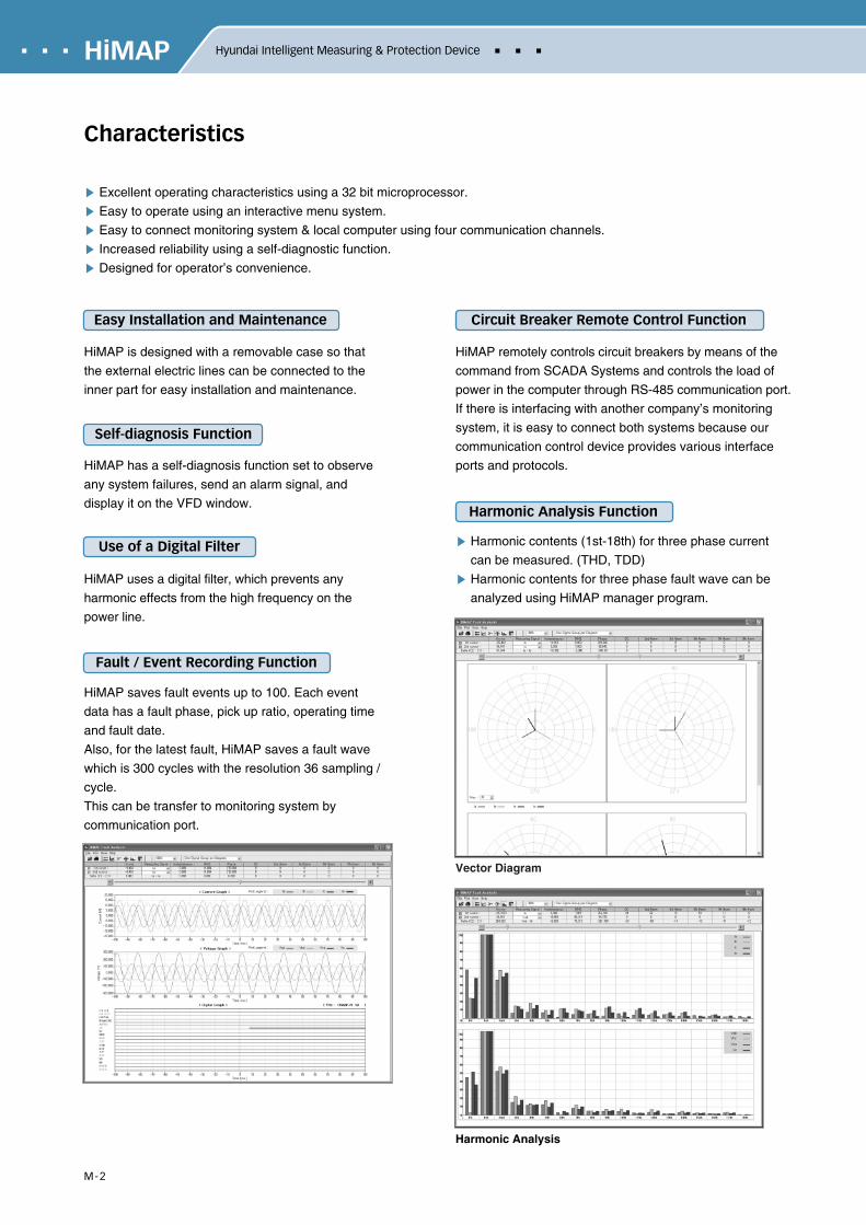
HiMAP saves fault events up to 100. Each event
data has a fault phase, pick up ratio, operating time
and fault date.
Also, for the latest fault, HiMAP saves a fault wave
which is 300 cycles with the resolution 36 sampling /
cycle.
This can be transfer to monitoring system by
communication port.
Excellent operating characteristics using a 32 bit microprocessor.
Easy to operate using an interactive menu system.
Easy to connect monitoring system & local computer using four communication channels.
Increased reliability using a self-diagnostic function.
Designed for operator’s convenience.
Easy Installation and Maintenance
HiMAP remotely controls circuit breakers by means of the
command from SCADA Systems and controls the load of
power in the computer through RS-485 communication port.
If there is interfacing with another company’s monitoring
system, it is easy to connect both systems because our
communication control device provides various interface
ports and protocols.
Harmonic contents (1st-18th) for three phase current
can be measured. (THD, TDD)
Harmonic contents for three phase fault wave can be
analyzed using HiMAP manager program.
Circuit Breaker Remote Control Function
Harmonic Analysis Function
Use of a Digital Filter
Self-diagnosis Function
Fault / Event Recording Function
Vector Diagram
Harmonic Analysis
M-3
HiMAP
HiMAP has a measuring function as shown in the below table. It displays the value of each measurement on the
VFD window by operating a menu key and then transfers and displays the data on the HIMIX window, which has an
outside digital indicator connected by a communication cable.
Various kinds of measuring values are converted to a primary value by input of a CT/PT ratio and then displayed on
the VFD window.
Measuring
Voltage(Vr, Vs, Vt, Vo, Vps, Vns, Vavg, Vomax)
Current(Ir, Is, It, Io, Ips, Ins, Iavg, ITHD, ITDD)
Frequency
Real Power
Reactive Power
Accumulated Real Energy
Accumulated Reactive Energy
Power Factor
Pow
er
0-99999999 kW
0-99999999 kvar
0-99999999 kWh
0-99999999 kvarh
-1.0-1.0 PF
45-65Hz
0-999999V
0-999999A
±0.2
±0.2
±0.2
±0.5
±1.0
±1.0
±0.5
±0.01Hz
※ CT/PT ratio will be set by using relay control keys and then displayed via VFD window.The values will be saved at flash memory even though the power line will be off.
Display Accuracy (%)
Model
HiMAP–FI
HiMAP–M
HiMAP-T
HiMAP-SC
Protection Object
Incoming Feeder
Motor
Transformer
Syncro-Check
•OCR(50/51) •OCGR(50G/51G) •DGR(67G) •DOCR(67)•SGR(67G) •OVR(59) •OVGR(64) •DOCGR(67N)•UVR(27) •PSR(47P/47N) •Trip coil supervision(94) (Option)
•OCR(50) •51LR •THR(49) •NSR(46) •NCHR(66) •UCR(37) •OCGR(50G/51G) •DGR(67G) •SGR(67G) •DFR(87M) •Closing/Trip coil supervision(94)(Option)
•DFR(87T) •OCR(50/51P)* •OCR(50/51S)*
•OCGR(50G/51G) •DGR(67G) •SGR(67G) •Closing/Trip coil supervision(94)(Option)
•SCR(25) •UVR(27)
Relay Function
* HiMAP-T Type has 2 OCRs. P means primary and S means secondary.
Protection Relay Function
Measuring Function
HICM-PC(II)
Communication Control Device
Ethernet
Type of Communication
Modbus / TCP
Protocol
Communication Function
HiMAP has four communication ports. RS-485 ports transfer all information related to relay operation status,
measuring information, and operation status of circuit breakers. This information is then perceived by HiMAP and
sent to communication control device at the speed of 62.5 K bps, using RS-485 HDLC frame protocol and
MODBUS-RTU protocol.
The communication control device connects a master PC to the Power Management System (HIPMS) at the speed
of 10M bps by Ethernet, TCP/IP. Please refer to the HIPMS manual for details on the monitoring function.
HIMIX communication port transfers kinds of measuring values optional to HIMIX at the speed of 9600 bps.
The external port of HiMAP transfers the fault record from a site to the PC for analysis, changes the relay element
value to a correct one, and is an RS-232C communication port to monitor the status of all kinds of protection relay.
Interface with SCADA

M-4
HiMAP Hyundai Intelligent Measuring & Protection Device
Display
Display Window(VFD)
Internal Case
Exterior Case
Input Key
Movement Key
ACK
System Status Indicator(Normal Operation, System Fail, Fault)
CB Status
CB Control
Select Switch & Led
RS232 Port
Set
Display Key
Front View

M-5
HiMAP
Item Point
Input
Output
AI Voltage
AI Current
DI
DO
4
4
5
Default*
Default*
Default
Default(R1-R7) (21-34)
31, 32(R6): Remote CB On
33, 34(R7): Remote CB Off
7
Remark
Item
Rating
Accuracy
Temperature
Insulation
Resistance
Voltage
Withstand
Overland
Withstand
Current
Voltage
Frequency
Measuring
Protection Relaying
Operation Guarantee
Restoration Guarantee
Circuits-Ground
Between Circuits
Between Contacts
Power Frequency
Lightning Impulse
Current Circuit
Voltage Circuit
Control Power
1A or 5A, Burden: Below 0.1VA/Phase
110V or 190V, Burden: Below 0.3VA/Phase
50Hz or 60Hz
±0.2%
±2%
-10 - 55
-25 - 70
10 MΩ
5 MΩ
5 MΩ
AC 60Hz 2000V/1 Min
1.2/50 5 kV
Rating Current×3: 3 hours / Rating Current × 20: 2sec
Rating Voltage × 3: 3 hours
Rating Voltage × 1.3: 3 hours
Maximum 300 ms
AC/DC 95V - 250V 50/60Hz, DC 48V
IEC 60255 / KEMC 1120 / IEC 61000-4
RS-485 Multi Drop
HD-BUS / DNP 3.0 / MODBUS
202.5(W) × 156(H) × 251(D)
4.3kg
Control Power Interruption
Control Power
Standards
Communication Type
Protocol
Size
Weight
Specification
*HiMAP-87M(Self-balancing Type) : Current(7CH), Voltage(1CH)HiMAP-87M(Differential Type) : Current(7CH), Voltage(0CH)HiMAP-T : Current(7CH), Voltage(1CH)
Specification
I / O Point
M-6
HiMAP Hyundai Intelligent Measuring & Protection Device
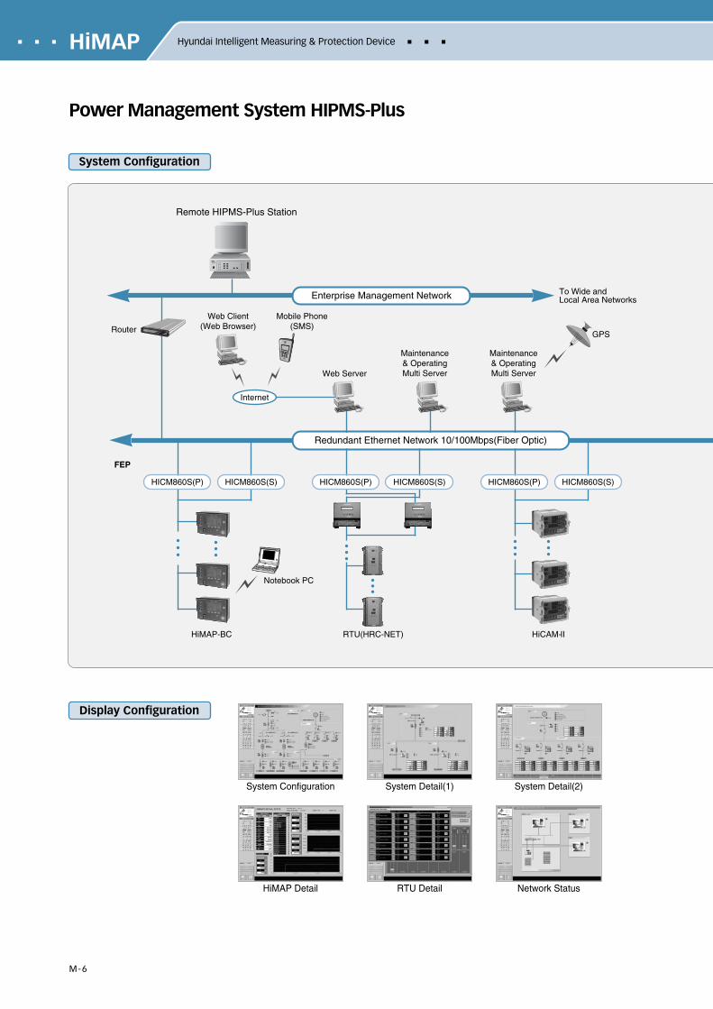
Power Management System HIPMS-Plus
System Configuration
Display Configuration
System Configuration System Detail(1) System Detail(2)
HiMAP Detail RTU Detail Network Status
Remote HIPMS-Plus Station
Enterprise Management Network
Router
Web Server
Maintenance& Operating Multi Server
Maintenance& Operating Multi Server
Web Client(Web Browser)
Mobile Phone(SMS)
GPS
To Wide andLocal Area Networks
RTU(HRC-NET)
FEP
Internet
Notebook PC
HICM860S(P) HICM860S(S)
HiMAP-BC
HICM860S(P) HICM860S(S)
HiCAM-II
HICM860S(P) HICM860S(S)
Redundant Ethernet Network 10/100Mbps(Fiber Optic)
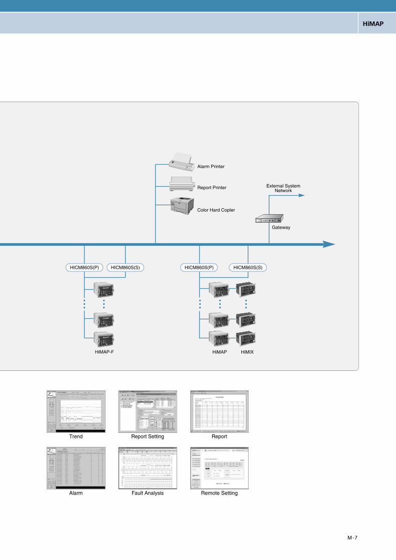
M-7
HiMAP
Trend Report Setting Report
Alarm Fault Analysis Remote Setting
Alarm Printer
Report Printer
Color Hard Copler
HiMAP-F
HICM860S(P) HICM860S(S)
HiMAP HiMIX
HICM860S(P) HICM860S(S)
Gateway
External SystemNetwork
M-8
HiMAP Hyundai Intelligent Measuring & Protection Device
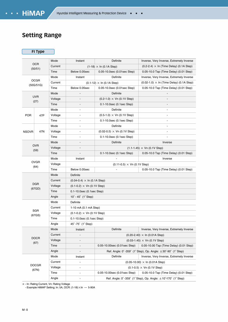
Setting Range
OCR
(50/51)
OCGR
(50G/51G)
UVR
(27)
OVR
(59)
OVGR
(64)
DGR
(67GD)
SGR
(67GS)
DOCR
(67)
DOCGR
(67N)
POR
NSOVR
47P
47N
Mode
Current
Time
Mode
Current
Time
Mode
Voltage
Time
Mode
Voltage
Time
Mode
Voltage
Time
Mode
Voltage
Time
Mode
Voltage
Time
Mode
Current
Voltage
Time
Angle
Mode
Current
Voltage
Time
Angle
Mode
Current
Voltage
Time
Angle
Mode
Current
Voltage
Time
Angle
Instant
Below 0.05sec
Instant
Below 0.05sec
-
-
-
-
-
-
-
-
-
-
-
-
Instant
Below 0.05sec
Instant
-
-
-
-
Instant
-
-
-
-
Definite
0.05-10.0sec (0.01sec Step)
Definite
0.05-10.0sec (0.01sec Step)
Definite
(0.2-1.0) × Vn (0.1V Step)
0.1-10.0sec (0.1sec Step)
Definite
(0.5-1.0) × Vn (0.1V Step)
0.1-10.0sec (0.1sec Step)
Definite
(0.02-0.5) × Vn (0.1V Step)
0.1-10.0sec (0.1sec Step)
Definite
0.1-10.0sec (0.1sec Step)
-
-
Definite
0.05-10.00sec (0.01sec Step)
Definite
0.05-10.00sec (0.01sec Step)
Inverse, Very Inverse, Extremely Inverse
(0.2-2.4) × In (Time Delay) (0.1A Step)
0.05-10.0 Tap (Time Delay) (0.01 Step)
Inverse, Very Inverse, Extremely Inverse
(0.02-1.0) × In (Time Delay) (0.1A Step)
0.05-10.0 Tap (Time Delay) (0.01 Step)
-
-
-
-
-
-
-
-
-
Inverse
0.05-10.0 Tap (Time Delay) (0.01 Step)
Inverse
0.05-10.0 Tap (Time Delay) (0.01 Step)
Inverse, Very Inverse, Extremely Inverse
0.05-10.00 Tap (Time Delay) (0.01 Step)
Inverse, Very Inverse, Extremely Inverse
0.05-10.0 Tap (Time Delay) (0.01 Step)
(1-18) × In (0.1A Step)
(0.1-12) × In (0.1A Step)
(1.1-1.45) × Vn (0.1V Step)
(0.11-0.5) × Vn (0.1V Step)
(0.20-2.40) × In (0.01A Step)
(0.03-1.45) × Vn (0.1V Step)
Ref. Angle: 0。-359。(1。Step), Op. Angle: ±30。-90。(1。Step)
(0.05-10.00) × In (0.01A Step)
(0.1-0.5) × Vn (0.1V Step)
Ref. Angle: 0。-359。(1。Step), Op. Angle: ±10。-170。(1。Step)
Definite
(0.04-0.4) × In (0.1A Step)
(0.1-0.2) × Vn (0.1V Step)
0.1-10.0sec (0.1sec Step)
10。- 45。(1。Step)
Definite
1-10 mA (0.1 mA Step)
(0.1-0.2) × Vn (0.1V Step)
0.1-10.0sec (0.1sec Step)
45。-75。(1。Step)
※ - In: Rating Current, Vn: Rating Voltage- Example HiMAP Setting; In: 5A, OCR: (1-18)×In → 5-90A
FI Type

M-9
HiMAP
Connection Diagram
R
CB GPT3rd
PT / GPT
CT
CT
ZCT
When using ZCT(SGR)
DISPLAY
CPU
50
51
50G
51G
27
47P
47N
59
64
67G
67
67N
S T
R S T
1
52a50
51
52
53
54
59
PControl
N
FG
52b
Remote
DI1
DI2
2
3
4
5
6
1
9
R1 21
22
23
24
25
26
27
28
29
30
31
32
33
34
Program-mable
Relay
Output
Local/RemoteCB On
Local/RemoteCB Off
NA
Option
Option
CCS
TCS
35
36
37
38
39
40
41
42
43
44
45
46
47
48
60
61
62
63
64
65
66
67
68
R2
R3
R4
R5
R6
R7
1011
1213
14
15
16
2
3
4
5
6
7
8
7
8
NA
RS485(Scada)
Vn
Vp
Vp
Vn RS485(HIMIX)
KEYBOARD
Power
DC 24 V
HiMAP-FI(3CT, 3PT)

M-10
HiMAP Hyundai Intelligent Measuring & Protection Device
Connection Diagram
R
CB
PT × 2
CT
ZCT
DISPLAY
CPU
50
51
50G
51G
27
47P
47N
59
64
67G
S T
R S T
52a50
51
52
53
54
59
FG
52b
Remote
1
9
R1 21
22
23
24
25
26
27
28
29
30
31
32
33
34
Program-mable
Relay
Output
Local/RemoteCB On
Local/RemoteCB Off
NA
Option
Option
CCS
TCS
35
36
37
38
39
40
41
42
43
44
45
46
47
48
60
61
62
63
64
65
66
67
68
R2
R3
R4
R5
R6
R7
1011
1213
14
15
16
2
3
4
5
6
7
8
NA
RS485(Scada)
RS485(HIMIX)
KEYBOARD
Vn
Vp
Vp
Vn
PControl
NPower
DC 24 V
DI1
DI2
HiMAP-FI(2CT, 2PT)

M-11
HiMAP
Terminal Block Pin Specification
HiMAP-FI Type
Control Power Terminal
P
N
(+)
(-)
FG
HIMIX Communication Terminal
66
67
68
Vp
Vn
N.A.
Communication Terminal
60
61
62
63
64
65
Vp
Vn
Vp
Vn Digital Input
41
42
43
44
45
46
47
48
N.A.
50
51
52
53
54
55
56
57
58
59
N.A.
Digital Output
R1
R2
R3
R4
R5
R6(CB On)
R7(CB Off)
N.A.
CCS
TCS
21
23
25
27
29
31
33
35
37
39
22
24
26
28
30
32
34
36
38
40
Analog Input
1
3
5
7
9
11
13
15
17
19
2
4
6
8
10
12
14
16
18
20
52a
52b
Remote
D/I 1
D/I 2
Common(+24V)
Ia
Ib
Ic
Io
Va
Vb
Vc
Vo
N.A.
N.A.
Terminal No. Description Application5051525354
21-2223-2425-2627-2829-3031-3233-3435-3637-3839-40
CB On Status 52aCB Off Status 52b
Remote InputGeneral DIGeneral DI
R1R2R3R4R5
R6(CB On)R7(CB Off)
N.A.TCSTCS
FixedFixedFixed
VariableVariable
FixedFixedN.A.FixedFixed
ProgrammableRelay Output

M-12
HiMAP Hyundai Intelligent Measuring & Protection Device
Characteristic Curve
OCR & OCGR
DOCR
0.01
Inverse | OP LEVEL 0.05-10.0
0.01
Very Inverse | OP LEVEL 0.05-10.0
0.01
Extremely Inverse | OP LEVEL 0.05-10.0 DOCR
Op.CurrentIaIbIc
Ref.VoltVbcVcaVab

M-13
HiMAP
OVR OVGR
DGR / SGR / DOCGR
0.01
Inverse | OP LEVEL 0.05-10.0
0.01
Very Inverse | OP LEVEL 0.05-10.0
DGR
DOCGR
SGR

M-14
HiMAP Hyundai Intelligent Measuring & Protection Device
C. Ground Fault Function Selection
C
D
S
Item OCR(50/51) OCGR(50/51G) DGR(67G) /DOCGR(67N)
SGR(67G) OVR(59) UVR(27) OVGR(64) PSR(47P/47N)
Table 1 (FI)
C
D
S
Table 3 (87M)
C
D
S
Table 4 (T)
C
D
S
Table 2 (M)
Order Form
※ Type of 87M (Protection for big motor): ( ) self-balancing type / ( ) differential type
NoteGround fault function shell be selected in accordance with the system ground method.
- OCGR (50G/51G): Effective ground system
- DGR (67G): Resister ground system
- SGR (67G): Floated ground system
※ 1) OCR P is transformer primary OCR2) OCR S is transformer secondary OCR3) The control voltage of HiMAP is only allow AC / DC 95 - 250V, 50 / 60Hz as a free voltage4) TCS(Trip Coil Supervision): Circuit breaker coil disconnection check. (option)
HiMAP – ❶ – ❷ ❸ – ❹ (Option)
❶ ❷ ❸ ❹ (option) 4)
Relay TypeFIM
87MT
SY
Feeder/IncomingMotorBig MotorTransformerSynchro check
Ground Fault TypeCDS
OCGRDGR / DOCGRSGR
CommunicationCXM
RS-485 HDLCNo System InterfaceMODBUS-RTU
TCS FunctionTX
RequiredNot Apply
A. Type Selection of HiMAP Please check mark(⋎) into the type required.
B. System Specification Required Please check mark(⋎) into a parenthesis.
1) Measuring Current (CT) Inputs for OCR: ( ) 5A / ( ) 1A
2) Measuring Zero Phase Current (ZCT) Inputs for GFR: ( ) 5A / ( ) 1A / ( ) 1.5 mA
3) Frequency 3): ( ) 50Hz / ( ) 60Hz
4) Measuring Voltage (line to ground) inputs: ( ) 110V / ( ) 190V / Others ( V)
Item
Item
Item DFR OCR P(50/51P) 1) OCR S(50/51S) 2) OCGR(50/51G) DGR(67G) /DOCGR(67N)
SGR(67G)
87M MPR OCGR(50/51G) DGR(67G) /DOCGR(67N)
SGR(67G)
MPR OCGR(50/51G) DGR(67G) /DOCGR(67N)
SGR(67G)

M-15
HiMAP
View & Dimension
33 218
185
138
139
186
251206
156
Weight 4.3Kg
Top View
Side View
Rear View
Panel Cut-out Dimension
Front View

HiCAM-II Hyundai Intelligent Communication &Measuring Device
Characteristics C-2
Display C-2
Connection Diagram C-4
Terminal Block Pin Specification C-5
View & Dimension C-6
C-2
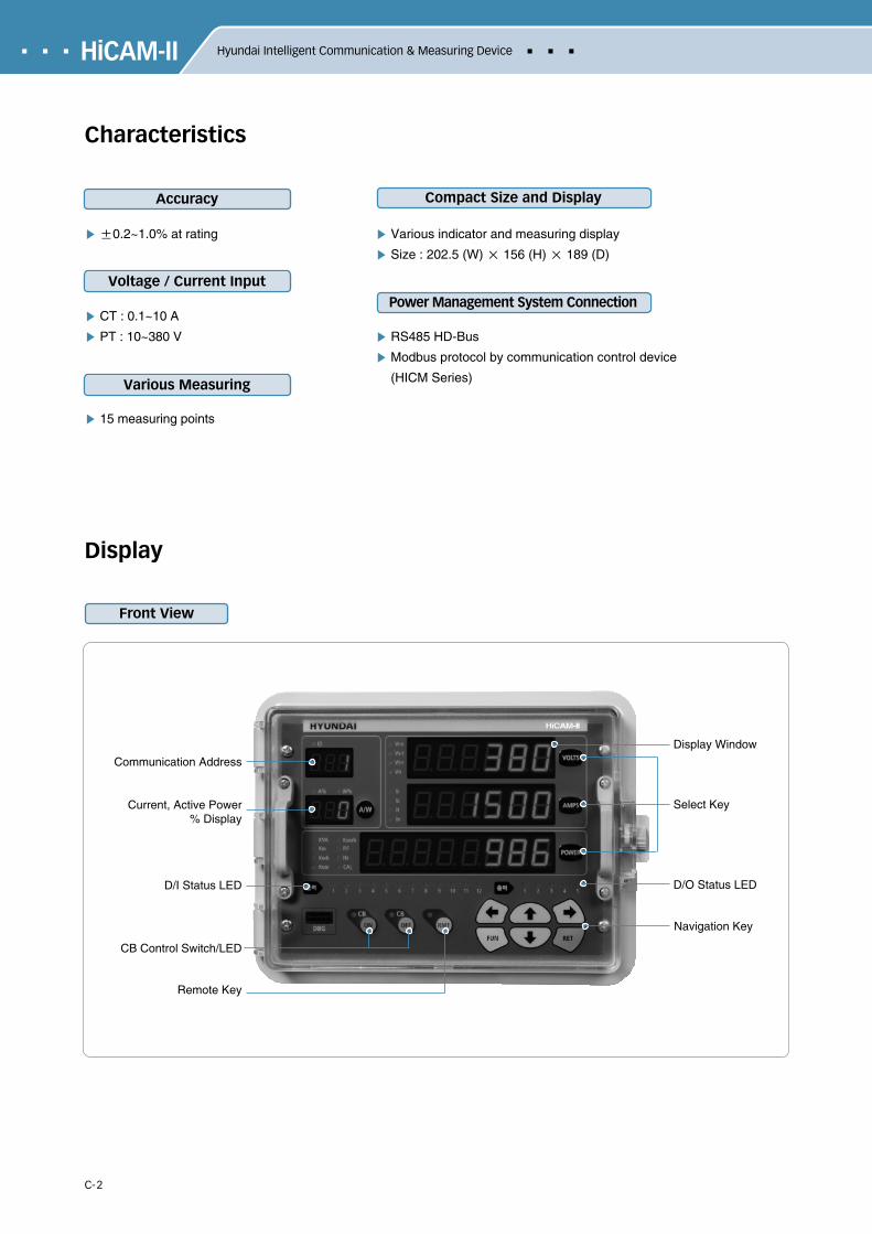
HiCAM-II Hyundai Intelligent Communication & Measuring Device
Characteristics
Display
Front View
Communication Address
Display Window
Select KeyCurrent, Active Power% Display
D/O Status LED
Navigation Key
D/I Status LED
CB Control Switch/LED
Remote Key
Various indicator and measuring display
Size : 202.5 (W) × 156 (H) × 189 (D)
RS485 HD-Bus
Modbus protocol by communication control device
(HICM Series)
±0.2~1.0% at rating
CT : 0.1~10 A
PT : 10~380 V
15 measuring points
Accuracy
Voltage / Current Input
Various Measuring
Compact Size and Display
Power Management System Connection

C-3
HiCAM-II
Item
Rating
Accuracy
Temperature
InsulationResistance
Voltage Withstand
OverlandWithstand
Current
Voltage
Frequency
Measuring
Operation Guarantee
Restoration Guarantee
Circuit-Ground
Between Circuits
Between Contacts
Power Frequency
Lightning Impulse
Current Circuit
Voltage Circuit
Control Power
1 A or 5 A(0.1 A~10 A), Burden : Below 0.1 VA / Phase
110 V or 190 V(10 V~380 V), Burden : Below 0.3 VA / Phase
50 Hz or 60 Hz
±0.2 %
-10 ~ 55
-25 ~ 70
10
5
5
AC 60 Hz 2,000V/1 Min
1.2/50 5 kV
Rating Current×3 : 3 hours / Rating Current×20 : 1 sec
Rating Voltage×3 : 3 hours
Rating Voltage×1.3 : 3 hours
AC 85 ~ 264 V (50 / 60 Hz), DC 90 ~ 120 V
18 VA, AC 220 V
RS–485 / Multi Drop
HD-BUS / Modbus
KEMC1110, IEC1036
202.5 (W)×156 (H)×189 (D)
1.5 Kg
Control Power
Power Consumption
Communication Type
Protocol
Standards
Size
Weight
Specification
Item Point
Input
Output
AI Voltage
AI Current
DI
DO
4
4
12
Default
Default
Default(41~55)
Default(31~40)37, 38(D04) : Remote CB On39, 40(D05) : Remote CB Off31~36(D01~D03) use current demand output.
5
Remark
Measuring Display Accuracy
0~999999 V
0~999999 A
0~99999999 kW
0~99999999 kvar
0~99999999 kVA
0~99999999 kWh
0~99999999 kvarh
-1.0~1.0 PF
45~65 Hz
0~999999 kW
0~999999 kWh
Voltage
Current
Real Power
Reactive Power
Apparent Power
Accumulated Real Energy
Accumulated Reactive Energy
Power Factor
Frequency
Reverse Real Power
Reverse
±0.2%
±0.2%
±0.2%
±0.5%
±1.0%
±1.0%
±1.0%
±0.5%
±0.01 Hz
±0.5%
±1.0%
Line to Line Voltage
Phase Current
(-) Sign
(-) Sign
Remark
Specification
I / O Point
Measuring

C-4
HiCAM-II Hyundai Intelligent Communication & Measuring Device
Connection Diagram
Remote CB On : 37, 38 TerminalRemote CB Off : 39, 40 Terminal
Remote CB On : 37, 38 TerminalRemote CB Off : 39, 40 Terminal
Remote CB On : 37, 38 TerminalRemote CB Off : 39, 40 Terminal
Remote CB On : 37, 38 TerminalRemote CB Off : 39, 40 Terminal
3P 4W 3PT_3CT 3P 3W 2PT_2CT
3P 3W 3PT_3CT 3P 3W 2PT_3CT
PT/GPT
45/50/55 41 42 43 44 46 47 48 49 51 52 53 54
91011121314
1516
1234567
R5
40 39 38 37 36 35 34 33 32 31
LN
FG
R4 R3 R2 R18
DI
AI
DO
COMM.
GPT
CT
R S T N
AD/DC95~250V50/60Hz
66Vp
67Vn
686970
PT
45/50/55 41 42 43 44 46 47 48 49 51 52 53 54
91011121314
1516
1234567
R5
40 39 38 37 36 35 34 33 32 31
LN
FG
R4 R3 R2 R18
DI
AI
DO
COMM.
CT
R S T
AD/DC95~250V50/60Hz
66Vp
67Vn
686970
PT
45/50/55 41 42 43 44 46 47 48 49 51 52 53 54
91011121314
1516
1234567
R5
40 39 38 37 36 35 34 33 32 31
LN
FG
R4 R3 R2 R18
DI
AI
DO
COMM.
CT
R S T
AD/DC95~250V50/60Hz
66Vp
67Vn
686970
PT
45/50/55 41 42 43 44 46 47 48 49 51 52 53 54
91011121314
1516
1234567
R5
40 39 38 37 36 35 34 33 32 31
LN
FG
R4 R3 R2 R18
DI
AI
DO
COMM.
CT
R S T
AD/DC95~250V50/60Hz
66Vp
67Vn
686970

C-5
HiCAM-II
Terminal Block Pin Specification
Control Power Terminal
L
N
FG
(+)
(-)
FG
Terminal
56
57
58
59
60
61
62
63
64
65
N.A.
Communication Terminal
66
67
68
69
70
Digital Input
41
42
43
44
45
46
47
48
49
50
51
52
53
54
55
Vp
Vn
Vp
Vn
N.A.
52a
52b
Remote
DI 1
Common(+24V)
DI 2
DI 3
DI 4
DI 5
Common(+24V)
DI 6
DI 7
DI 8
DI 9
Common(+24V)
Digital Output
31
32
33
34
35
36
37
38
39
40
R1(+)
R1(-)
R2(+)
R2(-)
R3(+)
R3(-)
R4(CB On)
R4(CB On)
R5(CB Off)
R5(CB Off)
Analog Input
1
3
5
7
9
11
13
15
17
19
2
4
6
8
10
12
14
16
18
20
Ia
Ib
Ic
Io
Vab
Vbc
Vca
Vo
N.A.
N.A.
Terminal No. Description Application
31~32
33~34
35~36
37~38
39~40
41
42
43
44
45
46
47
48
49
50
51
52
53
54
55
R1
R2
R3
R4(Remote On)
R5(Remote Off)
CB On Status 52a
CB Off Status 52b
Remote Input
General DI
Common
General DI
General DI
General DI
General DI
Common
General DI
General DI
General DI
General DI
Common
Variable
Fixed
Fixed
Fixed
Variable
HiCAM Self Power +24V
Variable
HiCAM Self Power +24V
Variable
HiCAM Self Power +24V

C-6
HiCAM-II Hyundai Intelligent Communication & Measuring Device
View & Dimension
138
185
33 141 15
189
206
156
186
139
Weight 1.5Kg
Top View
Side View
Rear View
Panel Cut-out Dimension
Front View

HH
IS-W
C-S
E-B
11-04, 2009.12 Designed by M
ER
MO
NT
Head Office 1, Jeonha-dong, Dong-gu, Ulsan, Korea Tel: 82-52-202-8101~8 Fax: 82-52-202-8100
Seoul 140-2, Gye-dong, Jongno-gu, Seoul, Korea(Sales & Marketing) Tel: 82-2-746-7579, 7523 Fax: 82-2-746-7648
Orlando 3452 Lake Lynda Drive, Suite 170, Orlando, Florida 32817, U.S.A. Tel: 1-407-249-7350 Fax: 1-407-275-4940
New Jersey 300 Sylvan Avenue, Englewood Cliffs, NJ 07632, U.S.A. Tel: 1-201-816-0286 Fax: 1-201-816-4083
London 2nd Floor, The Triangle, 5-17 Hammersmith Grove, London, W6 0LG, UKTel: 44-20-8741-0501 Fax: 44-20-8741-5620
Tokyo 8th Fl., Yurakucho Denki Bldg.1-7-1, Yuraku-cho, Chiyoda-gu, Tokyo, 100-0006, JapanTel: 81-3-3212-2076, 3215-7159 Fax: 81-3-3211-2093
Osaka I-Room 5th Fl. Nagahori-Plaza Bldg. 2-4-8, Minami Senba, Chuo-Ku, Osaka, 542-0081, JapanTel: 81-6-6261-5766, 5767 Fax: 81-6-6261-5818
Dubai Level 2, Unit 205, Emaar Square-Bldg.4 Sheikh Zayed Road, P.O.Box 252458, Dubai, U.A.E.Tel: 971-4-425-7995 Fax: 971-4-425-7996
Sofia 1271, Sofia 41, Rojen Blvd., Bulgaria Tel: 359-2-803-3200 Fax: 359-2-803-3203
Yangzhong No. 9 Xiandai Road, Xinba Scientific and Technologic Zone, Yangzhong, Jiangsu, P.R.C. Zip: 212212, ChinaTel: 86-511-8842-0666, 0212 Fax: 86-511-8842-0668, 0231