Hytork XL Pneumatic Actuator · The safety function for Hytork XL pneumatic actuator is defined as...
17
SIL Safety Manual DOC.SILM.HXL.EN Rev. 0 May 2015 Hytork XL Pneumatic Actuator SIL Safety Manual
Transcript of Hytork XL Pneumatic Actuator · The safety function for Hytork XL pneumatic actuator is defined as...

SIL Safety ManualDOC.SILM.HXL.EN Rev. 0
May 2015
Hytork XL Pneumatic ActuatorSIL Safety Manual


Hytork XL SeriesDOC.SILM.HXL.EN, Rev. 0
Table of ContentsMay 2015
ITable of Contents
Table of Contents
Section 1: Functional Specification ���������������������������������������1
Section 2: Configuration of the Product ��������������������������������2
Section 3: Service Condition Limitations �������������������������������3
Section 4: Expected Lifetime �������������������������������������������������4
Section 5: Failure Modes and Estimated Failure Rates �����������5
Section 6: Installation and Site Acceptance Procedure ����������6
Section 7: Periodic Test and Maintenance Requirements �������77.1 General ...................................................................................................... 77.2 Full-Stroke Test .......................................................................................... 77.3 Partial-Stroke Test ...................................................................................... 87.4 Proof Test and Periodic Maintenance .......................................................... 8
Section 8: Hardware Fault Tolerance �������������������������������������9
Section 9: Classification ������������������������������������������������������10
Section 10: Safe Failure Fraction �������������������������������������������11
Section 11: Mean Repair Time ����������������������������������������������12

Functional Specification
Section 1: Functional SpecificationThe safety function for Hytork XL pneumatic actuator is defined as follows: Double-Acting Scenario:
a. When an unsafe condition is detected in a plant by a process sensor, the controller, via actuator control system, drives the Actuator to close the shut-down valve, depressurizing (if under pressure) the Opening side of the actuator and pressurizing the Closing side of the actuator.
b. When an unsafe condition is detected in a plant by a process sensor, the controller, via actuator control system drives the Actuator to open the blow-down valve, depressurizing (if under pressure ) the Closing side of the pneumatic actuator and pressurizing the Opening side of the pneumatic actuator.
Single-Acting Scenario:
a. When an unsafe condition is detected in a plant by a process sensor, the controller, via actuator control system drives the Actuator to rotate with sufficient torque to move a valve to its fail-safe state when hold-position air pressure is released.
The Hytork XL brand Actuator Selection Procedure provides functional definition with specifics on input variables and performance.
In any case, the choice of the safety function to be implemented is responsibility of the system integrator.
1
May 2015
SIL Safety ManualDOC.SILM.HXL.EN, Rev. 0
Section 1: Functional Specification
Configuration of the Product
Section 2: Configuration of the ProductThe Hytork XL are pneumatically operated actuators designed to operate Ball / Plug / Butterfly valves, automation of louvers and dampers & automation of any quarter-turn mechanism. Both the double-acting and single-acting (spring-return) versions of the Hytork XL pneumatic actuators are designed in such a way that there are no moving parts on the outside (with the exception of the position indicator). This makes them safe, easy to install and virtually maintenance free.
For further details about actuator configurations, please refer to the Hytork XL product data sheets, Safety guide and Installation, Operation and Maintenance manual.
NOTE:
This product is only intended for use in large-scale fixed installations excluded from the scope of Directive 2011/65/EU on the restriction of the use of certain hazardous substances in electrical and electronic equipment (RoHS 2).
SIL Safety ManualDOC.SILM.HXL.EN, Rev. 0 May 2015
2
Section 2: Configuration of the Product
Service Condition Limitations (Limitation of Use)
Section 3: Service Condition Limitations (Limitation of Use)The operating capabilities are listed below:
• Maximum Operating Pressure:
— Pneumatic Service
— Up to 8 Barg (116 PSIg)
• Ambient Temperature: Temperature extremes require different solutions to maintain actuator operational integrity and reliability. For each Hytork XL actuator is available in three different temperature executions.
— -20°C to +100°C (-4°F to +212°F) Standard temperature
— -20°C to +120°C (-4°F to +248°F) High Temperature
— -40°C to +100°C (-40°F to +212°F) Low Temperature
• Torque Output Range:
— Double-Acting Hytork XL actuators, requiring pressure to rotate in either direction, are available with a torque range between 10 Nm (83 lbf.in) and 4,702 Nm (47,250 lbf.in)
— The Hytork XL spring-return models require pressure in only one direction of travel and are suitable for air-fail close and air-fail to open applications without modification. These models are available with a spring end torque between 4 Nm (32 lbf.in) and 1525 Nm (13,494 lbf.in)
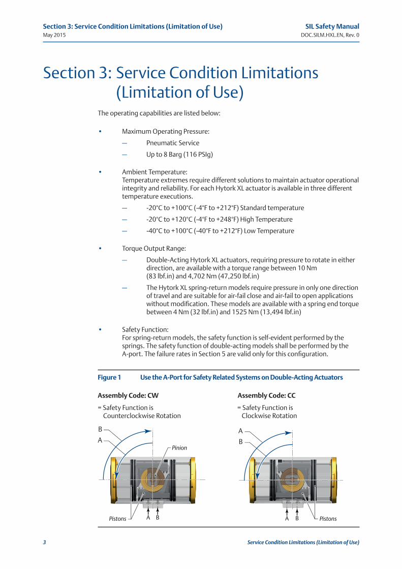
• Safety Function: For spring-return models, the safety function is self-evident performed by the springs. The safety function of double-acting models shall be performed by the A-port. The failure rates in Section 5 are valid only for this configuration.
Figure 1 Use the A-Port for Safety Related Systems on Double-Acting Actuators
Assembly Code: CW Assembly Code: CC
= Safety Function is = Safety Function is Counterclockwise Rotation Clockwise Rotation
A B A B
A
B A
B
Pistons Pistons
Pinion
3
May 2015
SIL Safety ManualDOC.SILM.HXL.EN, Rev. 0
Section 3: Service Condition Limitations (Limitation of Use)
Expected Lifetime
Section 4: Expected LifetimeActuator lifetime (for which failure rates indicated in Par. 5 are ensured) strongly depends on operating conditions.
For normal service conditions, Hytork XL actuators can be in good conditions also after more than 10 years with planned minimum maintenance. Normal working life is the number of cycles as defined in Table 1 of EN 15714-3. Hytork XL carry a warranty period of:
• 18 months after delivery if properly stored in conditions that we declare or
• 12 months after installation on site.
SIL Safety ManualDOC.SILM.HXL.EN, Rev. 0 May 2015
4
Section 4: Expected Lifetime

Failure Modes and Estimated Failure Rates
Section 5: Failure Modes and Estimated Failure RatesTable 1� Failure Rates – Hytork XL Pneumatic Actuator
Failure CategoryFailure Rate (in FIT)
Spring-Return Double-ActingFail Safe 96 0Fail Dangerous Undetected 302 397No Effect 1662 1762
The failure rates for the Hytork XL pneumatic actuator when performing partial valve stroke testing are listed in the table below:
Table 2� Failure Rates – Hytork XL Actuator with partial valve stroke testing
Failure CategoryFailure Rate (in FIT)
Spring-Return Double-ActingFail Safe 96 0Fail Dangerous Detected 178 207Fail Dangerous Undetected 124 190No Effect 1662 1762
NOTICENo internal diagnostics is included in the device. These values are valid when taken in account the maintenance interval and procedure described in Section 7, and for the expected lifetime defined in Section 4.
5
May 2015
SIL Safety ManualDOC.SILM.HXL.EN, Rev. 0
Section 5: Failure Modes and Estimated Failure Rates
Installation and Site Acceptance Procedure
Section 6: Installation and Site Acceptance ProcedureAny necessary installation and site acceptance procedures are discussed in the Hytork XL actuators Installation, Operation and Maintenance manual. The Installation, Operation and Maintenance manual defines exercising of the actuator after installation and defines testing after maintenance.
SIL Safety ManualDOC.SILM.HXL.EN, Rev. 0 May 2015
6
Section 6: Installation and Site Acceptance Procedure

Periodic Test and Maintenance Requirements
Section 7: Periodic Test and Maintenance Requirements
7�1 General
Please consider that the information in this paragraph are relevant only in regards of Reliability Tests; please refer to Doc. Installation, Operation and Maintenance manual for detailed information about product maintenance, handling and storage.
Diagnostic tests may be made to increase the system reliability (Full-Stroke or Partial-Stroke Test).
“On site” tests depend on Project/Plant facilities/requirements; however, a functional test must be executed on site, prior actuator operation.
7�2 Full-Stroke Test
The “Full-Stroke Test” (“On-line”) must be performed to satisfy the PFDAVG (average probability of failure on demand) value.
The full-test frequencies will be defined by the final integrator in relation to the defined SIL level to achieve.
• Procedure:
— Operate the Actuator/Valve assembly for No. 2 open/close complete cycles with complete closing of the valve.
— Verify the Correct performing of open – close manoeuvre (for example, check locally, or automatically via Logic solver, the correct movement of the actuator/valve).
Considering the application of the above described Full-Stroke Test procedure, the “Test Coverage” can be considered 99%.
7
May 2015
SIL Safety ManualDOC.SILM.HXL.EN, Rev. 0
Section 7: Periodic Test and Maintenance Requirements
Periodic Test and Maintenance Requirements
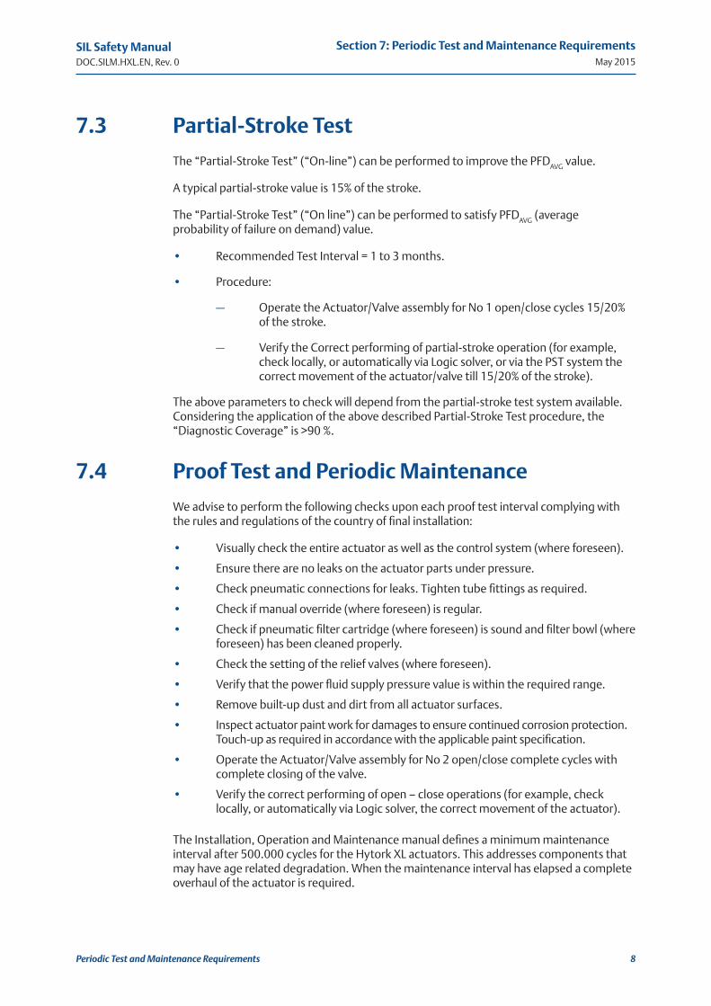
7�3 Partial-Stroke Test
The “Partial-Stroke Test” (“On-line”) can be performed to improve the PFDAVG value.
A typical partial-stroke value is 15% of the stroke.
The “Partial-Stroke Test” (“On line”) can be performed to satisfy PFDAVG (average probability of failure on demand) value.
• Recommended Test Interval = 1 to 3 months.
• Procedure:
— Operate the Actuator/Valve assembly for No 1 open/close cycles 15/20% of the stroke.
— Verify the Correct performing of partial-stroke operation (for example, check locally, or automatically via Logic solver, or via the PST system the correct movement of the actuator/valve till 15/20% of the stroke).
The above parameters to check will depend from the partial-stroke test system available. Considering the application of the above described Partial-Stroke Test procedure, the “Diagnostic Coverage” is >90 %.
7�4 Proof Test and Periodic Maintenance
We advise to perform the following checks upon each proof test interval complying with the rules and regulations of the country of final installation:
• Visually check the entire actuator as well as the control system (where foreseen).
• Ensure there are no leaks on the actuator parts under pressure.
• Check pneumatic connections for leaks. Tighten tube fittings as required.
• Check if manual override (where foreseen) is regular.
• Check if pneumatic filter cartridge (where foreseen) is sound and filter bowl (where foreseen) has been cleaned properly.
• Check the setting of the relief valves (where foreseen).
• Verify that the power fluid supply pressure value is within the required range.
• Remove built-up dust and dirt from all actuator surfaces.
• Inspect actuator paint work for damages to ensure continued corrosion protection. Touch-up as required in accordance with the applicable paint specification.
• Operate the Actuator/Valve assembly for No 2 open/close complete cycles with complete closing of the valve.
• Verify the correct performing of open – close operations (for example, check locally, or automatically via Logic solver, the correct movement of the actuator).
The Installation, Operation and Maintenance manual defines a minimum maintenance interval after 500.000 cycles for the Hytork XL actuators. This addresses components that may have age related degradation. When the maintenance interval has elapsed a complete overhaul of the actuator is required.
SIL Safety ManualDOC.SILM.HXL.EN, Rev. 0 May 2015
8
Section 7: Periodic Test and Maintenance Requirements

Hardware Fault Tolerance
Section 8: Hardware Fault ToleranceThe HFT of the device is 0.
The requirements of minimum hardware fault tolerance (HFT) according to Tab.6 of IEC 61511-1 have to be observed but, as long as has been performed an assessment report fully in compliance with IEC 61508 part 1 to7, alternative fault tolerance requirements have to be considered applicable according to Table 2 of IEC 61508-2 as per par. 11.4.5 of IEC 61511-1.
9
May 2015
SIL Safety ManualDOC.SILM.HXL.EN, Rev. 0
Section 8: Hardware Fault Tolerance

Classification
Section 9: ClassificationThe equipment is classified Type A according to IEC 61508-2.
SIL Safety ManualDOC.SILM.HXL.EN, Rev. 0 May 2015
10
Section 9: Classification
Safe Failure Fraction
Section 10: Safe Failure FractionSFF=0 without external diagnostic tests.
SFF>0 with external diagnostic tests, carried out according to definition 3.8.7 of IEC 61508-4.
• SFF = 91% with Partial-Stroke Test.
• SFF = 99% with Full-Stroke Test.
The SFF shall be evaluated for the entire final element sub-system.
The diagnostic test shall be performed considerably more often than the demand of the safety function.
11
May 2015
SIL Safety ManualDOC.SILM.HXL.EN, Rev. 0
Section 10: Safe Failure Fraction
Mean Repair Time
Section 11: Mean Repair TimeThe MRT of the device is 1 hour.
NOTICEThe MRT is estimated considering availability of skilled personnel for maintenance, spare parts and adequate tools and materials on site (that is, it encompasses the effective time to repair and the time before the component is put back into operation).
Procedures to repair or replace the Hytork XL actuators are provided in the respective Installation, Operation and Maintenance manual. Please refer to the Installation, Operation and Maintenance manual for any tools required for repair and replacement and required competency of technicians. Maintenance and subsequent test procedures are also covered in the Installation, Operation and Maintenance manual. Any failures, identified by the end-user during maintenance, repair or proof testing, that potentially impact the functional safety of the Hytork XL actuators should be reported back to Actuation Technologies Customer Service Coordinator.
SIL Safety ManualDOC.SILM.HXL.EN, Rev. 0 May 2015
12
Section 11: Mean Repair Time


For complete list of sales and manufacturing sites, please visit www.emerson.com/actuationtechnologieslocations or contact us at [email protected]
World Area Configuration Centers (WACC) offer sales support, service, inventory and commissioning to our global customers. Choose the WACC or sales office nearest you:
NORTH & SOUTH AMERICA
19200 Northwest FreewayHouston TX 77065USAT +1 281 477 4100F +1 281 477 2809
Av. Hollingsworth 325 Iporanga Sorocaba SP 18087-105BrazilT +55 15 3238 3788F +55 15 3228 3300
ASIA PACIFIC
No. 9 Gul Road#01-02 Singapore 629361T +65 6777 8211F +65 6268 0028
No. 1 Lai Yuan RoadWuqing Development AreaTianjin 301700P. R. ChinaT +86 22 8212 3300F +86 22 8212 3308
MIDDLE EAST & AFRICA
P. O. Box 17033DubaiUnited Arab EmiratesT +971 4 811 8100F +971 4 886 5465
P. O. Box 10305Jubail 31961Saudi ArabiaT +966 3 340 8650F +966 3 340 8790
24 Angus CrescentLongmeadow Business Estate East P.O. Box 6908 Greenstone 1616 Modderfontein Extension 5South AfricaT +27 11 451 3700F +27 11 451 3800
EUROPE
Berenyi u. 72- 100 Videoton Industry Park Building #230 Székesfehérvár 8000 HungaryT +36 22 53 09 50 F +36 22 54 37 00
www.emerson.com/hytork
©2017 Emerson. All rights reserved.
The Emerson logo is a trademark and service mark of Emerson Electric Co. HytorkTM is a mark of one of the Emerson family of companies. All other marks are property of their respective owners.
The contents of this publication are presented for information purposes only, and while every effort has been made to ensure their accuracy, they are not to be construed as warranties or guarantees, express or implied, regarding the products or services described herein or their use or applicability. All sales are governed by our terms and conditions, which are available on request. We reserve the right to modify or improve the designs or specifications of our products at any time without notice.